Proposed Method for Predicting the Elastic Shear Force ... · Proposed Method for Predicting the...
14
1 International Journal of Science and Engineering Investigations vol. 2, issue 19, August 2013 ISSN: 2251-8843 Proposed Method for Predicting the Elastic Shear Force Capacity of a Cracked Web Panel Sebastian B. Mendes Department of Civil and Environmental Engineering, University of Rhode Island, Kingston, RI, USA ([email protected]) Abstract-The growth of a diagonal fatigue crack in an I-shaped transversely stiffened steel plate girder loaded under predominantly shear may degrade the shear strength of an individual web panel. Analytical expressions were derived for the residual shear force capacity of a cracked web panel. Several limit states were considered including shear yielding, web buckling, brittle fracture, and impending ductile failure. The expressions were validated with finite element analyses and employed to investigate the governing limit states and associated strengths of various web panel geometries. Web buckling was found to be the predominant governing limit state for realistically sized girders. The formulated expressions may be employed in the design and analysis of girders considering prescribed diagonal fatigue crack configurations. Keywords- plate girder; shear capacity; web panel; fatigue crack; residual strength; web buckling; fracture; stability. I. INTRODUCTION I-shaped steel plate girders form an integral part of slab- girder highway bridges. These types of girders are constructed of individual plates welded together to form an I-shaped cross- section (see Fig. 1a). The dimensions of the plates are modified such that the safest design is achieved while material use is minimized. It follows from conventional beam theory that the web plate primarily resists internal shear forces while the tension and compression flange plates primarily resist internal bending moments [1]. A major consideration in the design of a girder is the avoidance of shear-based limit states including shear yielding of the web and web local buckling [2]. The shear force capacity of a girder corresponding to shear yielding may be increased by enlarging the gross cross-sectional area of the web. Similarly, the shear strength of a girder corresponding to web local buckling may be increased by modifying the dimensions of the web as well as adjusting additional parameters. It can be deduced from classical plate theory that the elastic buckling strength of a plate loaded under pure shear is maximized if the length-to-width ratio of the plate approaches unity [2]. For this reason, transverse stiffener plates are generally welded to the web and flanges at varying intervals along the length of the girder, effectively subdividing the web into individual panels bounded by the flanges and stiffener plates (see Fig. 1b) [2]. In regions of the girder loaded under predominantly shear, the web panels are effectively loaded under pure shear (see Fig. 1c) [2]. Hence, the modification of the spacings between the stiffener plates directly influences the buckling strengths of the web panels. The ongoing passage of vehicular traffic over a slab-girder bridge induces sub-critical cyclic bending moments and shear forces within the supporting girders [3]. These forces are directly coupled to fluctuating bending and shear stresses acting throughout a girder. High concentrations of fluctuating stress may form at inherent discontinuities in the girder. These discontinuities are generally attributable to flaws in the fillet welds connecting the web to the flanges and stiffener plates, and may include incomplete fusion, porosity, undercutting, and partial penetration [4]. The fluctuating stress concentrations may in time cause a pre-existing microcrack to grow into a through-thickness macrocrack [5, 6]. Figure 1. (a) I-shaped steel plate girder cross-section, (b) girder loaded under predominantly shear and subdivided into individual web panels by transverse stiffener plates, (c) web panel loaded under pure shear. In regions of a girder loaded under predominantly shear, a fatigue crack may continue to propagate under mixed-mode loading [7, 8]. In the most general case, a fatigue crack may initiate in a corner of a web panel at the junction of a flange and transverse stiffener plate (see Fig. 2a) [4, 9-14]. Primarily opening-mode loading (Mode I) complemented by low values
Transcript of Proposed Method for Predicting the Elastic Shear Force ... · Proposed Method for Predicting the...
1
International Journal of
Science and Engineering Investigations vol. 2, issue 19, August 2013
ISSN: 2251-8843
Proposed Method for Predicting the Elastic Shear Force
Capacity of a Cracked Web Panel
Sebastian B. Mendes
Department of Civil and Environmental Engineering, University of Rhode Island, Kingston, RI, USA ([email protected])
Abstract-The growth of a diagonal fatigue crack in an I-shaped transversely stiffened steel plate girder loaded under predominantly shear may degrade the shear strength of an individual web panel. Analytical expressions were derived for the residual shear force capacity of a cracked web panel. Several limit states were considered including shear yielding, web buckling, brittle fracture, and impending ductile failure. The expressions were validated with finite element analyses and employed to investigate the governing limit states and associated strengths of various web panel geometries. Web buckling was found to be the predominant governing limit state for realistically sized girders. The formulated expressions may be employed in the design and analysis of girders considering prescribed diagonal fatigue crack configurations.
Keywords- plate girder; shear capacity; web panel; fatigue
crack; residual strength; web buckling; fracture; stability.
I. INTRODUCTION
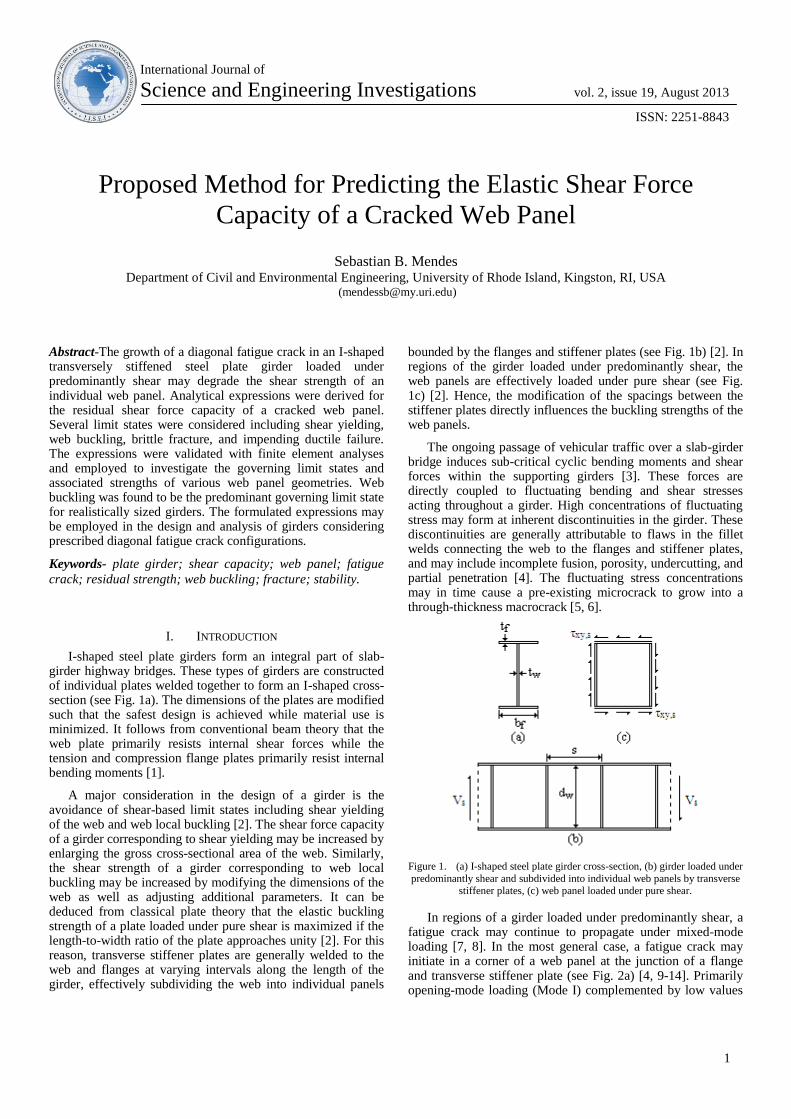
I-shaped steel plate girders form an integral part of slab-girder highway bridges. These types of girders are constructed of individual plates welded together to form an I-shaped cross-section (see Fig. 1a). The dimensions of the plates are modified such that the safest design is achieved while material use is minimized. It follows from conventional beam theory that the web plate primarily resists internal shear forces while the tension and compression flange plates primarily resist internal bending moments [1].
A major consideration in the design of a girder is the avoidance of shear-based limit states including shear yielding of the web and web local buckling [2]. The shear force capacity of a girder corresponding to shear yielding may be increased by enlarging the gross cross-sectional area of the web. Similarly, the shear strength of a girder corresponding to web local buckling may be increased by modifying the dimensions of the web as well as adjusting additional parameters. It can be deduced from classical plate theory that the elastic buckling strength of a plate loaded under pure shear is maximized if the length-to-width ratio of the plate approaches unity [2]. For this reason, transverse stiffener plates are generally welded to the web and flanges at varying intervals along the length of the girder, effectively subdividing the web into individual panels
bounded by the flanges and stiffener plates (see Fig. 1b) [2]. In regions of the girder loaded under predominantly shear, the web panels are effectively loaded under pure shear (see Fig. 1c) [2]. Hence, the modification of the spacings between the stiffener plates directly influences the buckling strengths of the web panels.
The ongoing passage of vehicular traffic over a slab-girder bridge induces sub-critical cyclic bending moments and shear forces within the supporting girders [3]. These forces are directly coupled to fluctuating bending and shear stresses acting throughout a girder. High concentrations of fluctuating stress may form at inherent discontinuities in the girder. These discontinuities are generally attributable to flaws in the fillet welds connecting the web to the flanges and stiffener plates, and may include incomplete fusion, porosity, undercutting, and partial penetration [4]. The fluctuating stress concentrations may in time cause a pre-existing microcrack to grow into a through-thickness macrocrack [5, 6].
Figure 1. (a) I-shaped steel plate girder cross-section, (b) girder loaded under
predominantly shear and subdivided into individual web panels by transverse stiffener plates, (c) web panel loaded under pure shear.
In regions of a girder loaded under predominantly shear, a fatigue crack may continue to propagate under mixed-mode loading [7, 8]. In the most general case, a fatigue crack may initiate in a corner of a web panel at the junction of a flange and transverse stiffener plate (see Fig. 2a) [4, 9-14]. Primarily opening-mode loading (Mode I) complemented by low values

International Journal of Science and Engineering Investigations, Volume 2, Issue 19, August 2013 2
www.IJSEI.com Paper ID: 21913-01 ISSN: 2251-8843
of sliding-mode loading (Mode II) may then cause the crack to propagate in a straight line diagonally through the web panel at an angle near to 45° relative to the flange (see Fig. 2b) [8, 15]. It can be foreseen that the continued growth of the crack may adversely affect the shear strength of the web panel, and concurrently the overall girder, corresponding to the limit states of shear yielding and local buckling. Furthermore, the presence of the crack introduces two additional limit states including brittle fracture and impending ductile failure [8]. Overall, the growth of a diagonal fatigue crack may bring about the premature occurrence of elastic limit states in a girder [16-22].
Figure 2. (a) Girder loaded under predominantly shear with diagonal fatigue
crack originating at a corner of a web panel, (b) diagonal fatigue crack within the web panel displaying the x-y and x’-y’ axis systems.
Many studies have investigated the influence of cracks and other discontinuities on the strength and stability of plate-like structures through the use of analytical, numerical, and experimental methods [23-36]. Far less research has analyzed the effects of through-thickness fatigue cracks on the shear strength and stability of plate girders and web panels [37, 38]. The bulk of related research has concentrated upon the influence of large discontinuities such as holes, slots, and copings on the shear strength and stability of beam-like structures [39-48]. The post-buckling behavior and associated tension field action of uncracked web panels has been thoroughly analyzed [49-51].
It may be useful for engineers to be able to design or otherwise analyze the elastic shear force capacity of plate girder web panels for prescribed diagonal fatigue crack configurations so as to avoid the occurrence of elastic limit states in between bridge inspection periods. The objective of this research was to derive analytical expressions for the elastic shear force capacity of a cracked web panel corresponding to the limit states of shear yielding of the web, web local buckling, brittle fracture, and impending ductile failure. This research concentrated upon elastic limit states, and the post-buckling behavior and tension field action of cracked web panels was not considered.
Several assumptions were made with regard to the formulation of the capacity expressions. It was assumed that
the portions of plate girder that the expressions are applicable to are loaded under predominantly shear (see Fig. 2a). The plate girder itself was assumed to be an I-shaped steel plate girder. The individual plates of the girder were assumed to be constructed of high-strength low-alloy structural steel [2]. As such, the steel was implied to be homogeneous and behave as a linear isotropic elastic material [52]. Also, the plates were assumed to be sufficiently thin enough for plane stress conditions to predominate. In accordance with conventional design procedures, the stress fields were derived relative to the defined coordinate axis systems and compared to the material strength [1, 2]. The web panel itself was assumed to have a depth, dw, and a width, s, designating the spacing between the stiffener plates (see Fig. 2b). The diagonal fatigue crack of length 2a was assumed to be through-thickness and loaded primarily by Mode I loading with minimal influence from Mode II loading. As such, the crack was assumed to propagate in a comparatively straight line from a corner of the web panel at an angle θ ≈ 45° relative to the flange (see Fig. 2b) [8].
Finite element (FE) analyses were performed using the general FE software ABAQUS to validate the capacity expressions. Upon validation, the capacity expressions were plotted as functions of crack length for various web panel geometries. Conclusions were drawn regarding the different capacities and limit states associated with the various web panel geometries. Finally, the applicability of the shear force capacity expressions was demonstrated with a simplified plate girder design problem.
II. WEB LOCAL BUCKLING
A. Approximation of Internal Shear Stress Distribution
Within Cracked Web Panel
It was previously acknowledged that a web panel located in a region of a girder loaded under predominantly shear is itself effectively loaded under pure shear [2]. This configuration is manifested in the form of uniform shear stress, τxy,s, acting along the perimeter of the web panel (see Fig. 1c). The perimeter shear stress is directly linked to and approximately equal to the internal shear stress within the web panel. Also, τxy,s is directly coupled to the external shear force, Vs, acting at that particular region of the girder (see Fig. 1b). The distribution of internal shear stress along the depth of the web is nearly uniform, and thus τxy,s may be approximated as the magnitude of Vs divided by the gross cross-sectional area of the web, expressed as [2]
ww
s
w
ssxy
td
V
A
V, (1)
where Aw is the gross cross-sectional area of the web and tw is the thickness of the web. The importance of τxy,s lies in its direct link to the internal shear stress, which itself has a direct influence upon the elastic buckling strength of the web panel [53].
The presence of a diagonal crack originating at a corner of a web panel (see Fig. 2b) may serve to influence the magnitude
International Journal of Science and Engineering Investigations, Volume 2, Issue 19, August 2013 3
www.IJSEI.com Paper ID: 21913-01 ISSN: 2251-8843
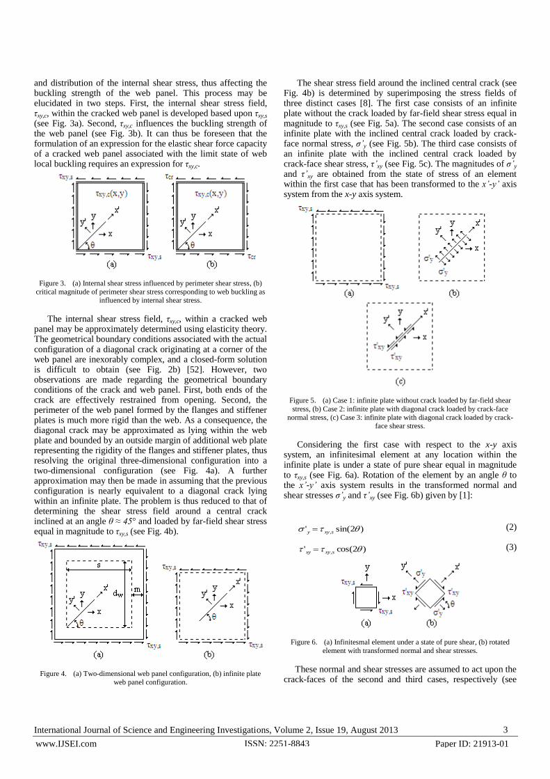
and distribution of the internal shear stress, thus affecting the buckling strength of the web panel. This process may be elucidated in two steps. First, the internal shear stress field, τxy,c, within the cracked web panel is developed based upon τxy,s (see Fig. 3a). Second, τxy,c influences the buckling strength of the web panel (see Fig. 3b). It can thus be foreseen that the formulation of an expression for the elastic shear force capacity of a cracked web panel associated with the limit state of web local buckling requires an expression for τxy,c.
Figure 3. (a) Internal shear stress influenced by perimeter shear stress, (b)
critical magnitude of perimeter shear stress corresponding to web buckling as influenced by internal shear stress.
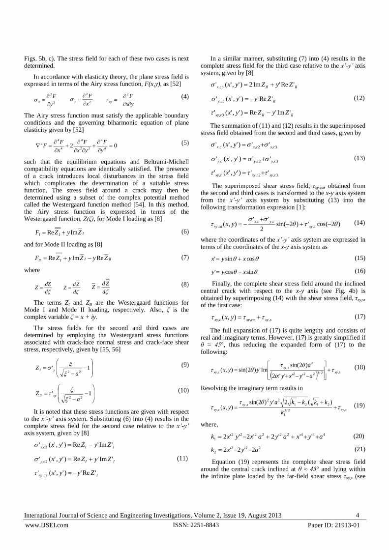
The internal shear stress field, τxy,c, within a cracked web panel may be approximately determined using elasticity theory. The geometrical boundary conditions associated with the actual configuration of a diagonal crack originating at a corner of the web panel are inexorably complex, and a closed-form solution is difficult to obtain (see Fig. 2b) [52]. However, two observations are made regarding the geometrical boundary conditions of the crack and web panel. First, both ends of the crack are effectively restrained from opening. Second, the perimeter of the web panel formed by the flanges and stiffener plates is much more rigid than the web. As a consequence, the diagonal crack may be approximated as lying within the web plate and bounded by an outside margin of additional web plate representing the rigidity of the flanges and stiffener plates, thus resolving the original three-dimensional configuration into a two-dimensional configuration (see Fig. 4a). A further approximation may then be made in assuming that the previous configuration is nearly equivalent to a diagonal crack lying within an infinite plate. The problem is thus reduced to that of determining the shear stress field around a central crack inclined at an angle θ ≈ 45° and loaded by far-field shear stress equal in magnitude to τxy,s (see Fig. 4b).
Figure 4. (a) Two-dimensional web panel configuration, (b) infinite plate
web panel configuration.
The shear stress field around the inclined central crack (see Fig. 4b) is determined by superimposing the stress fields of three distinct cases [8]. The first case consists of an infinite plate without the crack loaded by far-field shear stress equal in magnitude to τxy,s (see Fig. 5a). The second case consists of an infinite plate with the inclined central crack loaded by crack-face normal stress, σ’y (see Fig. 5b). The third case consists of an infinite plate with the inclined central crack loaded by crack-face shear stress, τ’xy (see Fig. 5c). The magnitudes of σ’y and τ’xy are obtained from the state of stress of an element within the first case that has been transformed to the x’-y’ axis system from the x-y axis system.
Figure 5. (a) Case 1: infinite plate without crack loaded by far-field shear
stress, (b) Case 2: infinite plate with diagonal crack loaded by crack-face
normal stress, (c) Case 3: infinite plate with diagonal crack loaded by crack-face shear stress.
Considering the first case with respect to the x-y axis system, an infinitesimal element at any location within the infinite plate is under a state of pure shear equal in magnitude to τxy,s (see Fig. 6a). Rotation of the element by an angle θ to the x’-y’ axis system results in the transformed normal and shear stresses σ’y and τ’xy (see Fig. 6b) given by [1]:
)2sin(' , sxyy (2)
)2cos(' , sxyxy (3)
Figure 6. (a) Infinitesmal element under a state of pure shear, (b) rotated
element with transformed normal and shear stresses.
These normal and shear stresses are assumed to act upon the crack-faces of the second and third cases, respectively (see
International Journal of Science and Engineering Investigations, Volume 2, Issue 19, August 2013 4
www.IJSEI.com Paper ID: 21913-01 ISSN: 2251-8843
Figs. 5b, c). The stress field for each of these two cases is next determined.
In accordance with elasticity theory, the plane stress field is expressed in terms of the Airy stress function, F(x,y), as [52]
2
2
y
Fx
2
2
x
Fy
yx
Fxy
2
(4)
The Airy stress function must satisfy the applicable boundary conditions and the governing biharmonic equation of plane elasticity given by [52]
024
4
22
4
4
44
y
F
yx
F
x
FF (5)
such that the equilibrium equations and Beltrami-Michell compatibility equations are identically satisfied. The presence of a crack introduces local disturbances in the stress field which complicates the determination of a suitable stress function. The stress field around a crack may then be determined using a subset of the complex potential method called the Westergaard function method [54]. In this method, the Airy stress function is expressed in terms of the Westergaard function, Z(ζ), for Mode I loading as [8]
III ZyZF ImRe (6)
and for Mode II loading as [8]
IIIIII ZyZyZF ReImRe (7)
where
d
dZZ '
d
ZdZ
d
ZdZ (8)
The terms ZI and ZII are the Westergaard functions for Mode I and Mode II loading, respectively. Also, ζ is the complex variable ζ = x + iy.
The stress fields for the second and third cases are determined by employing the Westergaard stress functions associated with crack-face normal stress and crack-face shear stress, respectively, given by [55, 56]
1'
22 aZ yI
(9)
1'
22 aZ xyII
(10)
It is noted that these stress functions are given with respect to the x’-y’ axis system. Substituting (6) into (4) results in the complete stress field for the second case relative to the x’-y’ axis system, given by [8]
IIcx ZyZyx 'Im'Re)','(' 2,
IIcy ZyZyx 'Im'Re)','(' 2, (11)
Icxy Zyyx 'Re')','(' 2,
In a similar manner, substituting (7) into (4) results in the complete stress field for the third case relative to the x’-y’ axis system, given by [8]
IIIIcx ZyZyx 'Re'Im2)','(' 3,
IIcy Zyyx 'Re')','(' 3, (12)
IIIIcxy ZyZyx 'Im'Re)','(' 3,
The summation of (11) and (12) results in the superimposed stress field obtained from the second and third cases, given by
3,2,, '')','(' cxcxcx yx
3,2,, '')','(' cycycy yx (13)
3,2,, '')','(' cxycxycxy yx
The superimposed shear stress field, τxy,ca, obtained from the second and third cases is transformed to the x-y axis system from the x’-y’ axis system by substituting (13) into the following transformation expression [1]:
)2cos(')2sin(2
''),( ,
,,
,
cxy
cycx
caxy yx (14)
where the coordinates of the x’-y’ axis system are expressed in terms of the coordinates of the x-y axis system as
cossin' xyx (15)
sincos' xyy (16)
Finally, the complete shear stress field around the inclined central crack with respect to the x-y axis (see Fig. 4b) is obtained by superimposing (14) with the shear stress field, τxy,s, of the first case:
sxycaxycxy yx ,,, ),( (17)
The full expansion of (17) is quite lengthy and consists of real and imaginary terms. However, (17) is greatly simplified if θ ≈ 45°, thus reducing the expanded form of (17) to the following:
sxy
sxy
cxy
ayxyix
ayyx ,2/3222
2
,
,
''''2
)2sin(Im')2sin(),(
(18)
Resolving the imaginary term results in
sxy
sxy
cxyk
kkkkayyx ,2/3
1
2121
22
,
,
)(2')2sin(),(
(19)
where,
444222222
1 '''2'2''2 ayxayaxyxk (20)
222
2 2'2'2 ayxk (21)
Equation (19) represents the complete shear stress field around the central crack inclined at θ ≈ 45° and lying within the infinite plate loaded by the far-field shear stress τxy,s (see

International Journal of Science and Engineering Investigations, Volume 2, Issue 19, August 2013 5
www.IJSEI.com Paper ID: 21913-01 ISSN: 2251-8843
Fig. 4b). In accordance with the aforementioned approximations, the shear stress field obtained from this configuration is approximately equivalent to the internal shear stress field obtained from the actual configuration of a cracked web panel with the diagonal crack originating at a corner of the web panel (see Fig. 3a). Importantly, it is noted that (19) is in part a function of τxy,s, and is therefore directly coupled to Vs by way of (1).
Close examination of (19) reveals that the distribution of τxy,c within a cracked web panel is quite complex. Magnitudes of shear stress much greater than τxy,s are especially prevalent in the local region around the crack. The distribution of τxy,c may be approximated by subdividing the web panel into equal-sized rectangular elements. The total number of elements, Ne, are arranged such that the number of element rows, re, are equal to the number of element columns, ce. Each element is designated by its row number, r, and column number, c, relative to the origin of the crack (see Fig. 7a). Also, each element is loaded under pure shear designated by τxy,e-rc. The magnitude of τxy,e-rc for each element is developed based upon τxy,c. Specifically, the magnitude of τxy,e-rc for each element is the value of τxy,c at the central point of the element (see Fig. 7b). It can be foreseen that a greater number of elements results in a higher degree of accuracy in describing the actual distribution of τxy,c.
Figure 7. (a) Web panel subdivided into rectangular elements displaying row
and column numbers, (b) individual panel element loaded under pure shear.
The magnitude of τxy,e-rc for any element is expressed in terms of τxy,c by setting x and y equal to the coordinates of the central point of the element, xrc and yrc, expressed as
e
oe
rcr
arsscx
2
cos22 (22)
e
oeww
rcc
acdrdy
2
sin22 (23)
where re and ce are expressed in terms of Ne as
eee Ncr (24)
and,
o (25)
Also, θ in (15), (16), and (19) is modified to take into account negative values of x:
rc
rcrc
ox
xx
2 (26)
Thus, the value of τxy,e-rc for any element is determined by substituting r, c, (24), and (25) into (22) and (23), and introducing the results into (19), implicitly expressed as
rcrccxyrcexy yx ,,, (27)
It is observed that since τxy,e-rc is a function of τxy,c, it is therefore also a function of τxy,s. Altogether, the varying values of τxy,e-rc for each element represent an approximation of the internal shear stress distribution, τxy,c, within the cracked web panel.
B. Buckling Strength of Cracked Web Panel
A closed-form solution for the elastic buckling strength of the cracked web panel is difficult to obtain using classical plate theory [2, 53]. This is primarily due to the non-uniform internal stress field caused by the presence of the crack, as well as the complex geometrical boundary conditions introduced by the crack. The Rayleigh-Ritz energy method employs the principle of stationary potential energy to approximate the buckling strength when complex boundary conditions are present [53]. In this method, the buckled shape of the cracked web panel is assumed to take on a form described by an out-of-plane displacement function, w(x”, y”), expressed in terms of the x”-y” axis system with the origin at the central point of the web panel (see Fig. 8). The displacement function satisfies all or most of the geometrical boundary conditions and includes an arbitrary set of variables, Ai, which control the shape of the displacement function, in the form
n
i
ii yxfAyxw1
)","()","( (28)
where n is the number of degrees of freedom of the displacement function. The total potential energy, П, of the panel is then formulated, expressed as [53]
dSuTdVUS
ii
V
(29)
where U is the strain energy density function, V is the volume of the panel, Ti are the applied surface tractions, ui are the displacements caused by the tractions, and S is the surface over which the tractions are applied. It is evident that the formulation of П essentially couples w(x”, y”) with the externally applied stress, τxy,s (see Fig. 8). The variation of П with respect to Ai is then set to zero, shown as [53]
0
iA
(30)
It follows that the critical external stress, τ’cr, enabling this equilibrium is an initial estimation of the buckling strength of the cracked web panel [53].

International Journal of Science and Engineering Investigations, Volume 2, Issue 19, August 2013 6
www.IJSEI.com Paper ID: 21913-01 ISSN: 2251-8843
Figure 8. Cracked web panel with externally applied perimeter shear stress
and corresponding out-of-plane displacement function.
The initial magnitude of τ’cr may be further developed by employing the web panel elements and the previously derived approximate internal shear stress distribution, τxy,e-rc. Specifically, the overall initial cracked web panel buckling strength is assumed to be uniformly distributed among each of the web panel elements. The strength of each element is further assumed to be degraded by the ratio of τxy,s to τxy,e-rc. In this way, the buckling strength of each element, τcr,e-rc, is equal to the product of the ratio of τxy,s to τxy,e-rc and the initial cracked web panel buckling strength, divided by the total number of elements, expressed as
rcexy
sxy
e
crrcecr
N ,
,
,
'
(31)
Each element is thus assumed to buckle when τxy,e-rc equals or exceeds τcr,e-rc. The corresponding critical value of τxy,s for each element may then be determined. It follows that the final estimation of the buckling strength of the cracked web panel, τcr, is the sum of the critical values of τxy,s.
An expression for w(x”, y”) for the overall cracked web panel is first required for the formulation of П and the determination of τ’cr. The geometrical boundary conditions concerning the edges of the web panel are conservatively assumed to be simply supported [2]:
0",2
y
sw 0",
2
y
sw
02
,"
wdxw
02
,"
wd
xw
(32)
The approximation is made that w(x”, y”) for the cracked web panel is nearly identical to w(x”, y”) for an uncracked web panel. The geometrical boundary conditions concerning the diagonal crack are therefore neglected, and w(x”, y”) is formulated based only upon the boundary conditions given by (32). In essence, the approximation is made that the initial buckling strength of the cracked web panel is dependent only upon the external shear stress, with w(x”, y”) remaining identical to w(x”, y”) for the uncracked web panel. A unilateral displacement function of the following form satisfies the boundary conditions given by (32):
wd
y
s
xAyxw
coscos)","( (33)
The formulation of П is developed by substituting (33) and τxy,s into (29), implicitly expressed as [53]
""
""2
2
2
2
2
,
2
2
2
2
dydxW
dydxUD
s
s
e
d
d
sxy
s
s
e
d
d
w
w
w
w
(34)
where,
22
2
2
2
2
2
2
2
2
2
"""")1(2
""
yx
w
y
w
x
w
y
w
x
wU e
(35)
and,
"" y
w
x
wWe
(36)
Also, the term D is the web panel rigidity given by [2]
2
3
112 wEt
D (37)
where E is the modulus of elasticity and ν is Poisson’s ratio. The initial cracked web panel buckling strength is then determined by introducing (34) into (30), solving for τxy,s, and dividing the result by tw, giving
""
""
2'
2
2
2
2
2
2
2
2
dydxW
dydxU
t
Ds
s
e
d
d
s
s
e
d
d
w
crw
w
w
w
(38)
where the arbitrary term A in (33) vanishes in accordance with calculus of variations [53].
The initial cracked web panel buckling strength is further refined by determining the buckling strengths of the web panel elements and summing the associated critical values of τxy,s. The external stress applied to each element is the previously derived pure shear stress τxy,e-rc given by (27) (see Fig. 7b). Equation (27) may be rewritten to be explicitly expressed in terms of τxy,s as

International Journal of Science and Engineering Investigations, Volume 2, Issue 19, August 2013 7
www.IJSEI.com Paper ID: 21913-01 ISSN: 2251-8843
1,, rcsxyrcexy C (39)
where Crc is a constant directly derived from (19) and partially dependent upon r, c, xrc, and yrc of a given element, expressed as
2/3
1
2121
22 )(2')2sin(
k
kkkkayCrc
(40)
The critical value of τxy,s corresponding to buckling of each element is determined by setting τxy,e-rc = τcr,e-rc, introducing (38) and (39) into (31), and solving for τxy,s, giving
""
""
122
2
2
2
2
2
2
2
2,
dydxW
dydxU
CtN
Ds
s
e
d
d
s
s
e
d
d
rcwe
rcecrw
w
w
w
(41)
Finally, the approximate buckling strength of the cracked web panel is determined by taking the sum of τcr,e-rc for all of the elements, expressed as
Y
N
r
N
c
rcecrcr
e e
1 1
, (42)
The term τY is the shear yield strength of the web panel steel given by [2]
3
YY
(43)
where σY is the yield strength of the web panel steel. Setting τcr = τxy,s, substituting (42) into (1), and solving for Vs results in the shear force capacity of a cracked web panel corresponding to the limit state of web local buckling:
wwcrcr tdV (44)
III. SHEAR YIELDING
The growth of the diagonal fatigue crack originating at a corner of the web panel reduces the gross cross-sectional area of the panel (see Fig. 9). From (1) it can be deduced that the reduction in gross cross-sectional area serves to decrease the shear force capacity corresponding to shear yielding. The reduced web panel depth, dwc, above the crack tip is given by
sin2add wwc (45)
Substituting (45) for dw and τY for τxy,s in (1), and solving for Vs results in
sin2adtV wwYcr (46)
The internal shear stress along dwc achieves shear yielding first at the crack tip and last at the perimeter of the web panel. The critical value of τxy,s corresponding to Vcr thus occurs when τxy,s equals the shear yield strength of the web panel steel, given by
Ycr (47)
Figure 9. Cracked web panel with reduced web panel depth.
IV. BRITTLE FRACTURE AND IMPENDING DUCTILE FAILURE
The propagation of the diagonal fatigue crack originating at a corner of the web panel (see Fig. 2b) is accompanied by a corresponding increase in the stress intensity factor, K, at the crack tip. This increase in K introduces two additional limit states including brittle fracture and impending ductile failure. Brittle fracture is characterized by the sudden rupture of the web panel and occurs when the fatigue crack grows to a critical length and K equals the critical stress intensity factor, Kc, of the web panel steel [8, 57]. Alternatively, impending ductile failure is characterized by the growth of the plastic region around the crack tip to a critical size and occurs when the crack length and K each equal a critical magnitude [57].
In accordance with linear elastic fracture mechanics (LEFM), the theoretical form of K is given by [8]
aK o (48)
where σo is the far-field Mode I or II stress acting upon the crack. As previously mentioned, the diagonal crack shown in Fig. 2b is loaded primarily by Mode I loading with minimal influence from Mode II loading when θ ≈ 45°. Employing the principle of superposition, the total stress intensity factor, KT, is the sum of the stress intensity factors derived from the Mode I and II loading, expressed by [8]
IIIT KKK (49)
where KI and KII are the stress intensity factors associated with Mode I and II loading, respectively. The magnitudes of KI and KII for the diagonal crack may be approximated by assuming once again that the actual configuration of the diagonally cracked web panel (see Fig. 2b) is nearly equivalent to the configuration of a diagonal crack inclined at an angle θ ≈ 45° and lying within an infinite plate loaded by far-field shear stress equal in magnitude to τxy,s (see Fig. 4b).
The Mode I and II stress intensity factors are derived from the state of stress of an element in the previously described configuration (see Fig. 4b) that has been transformed to the x’-

International Journal of Science and Engineering Investigations, Volume 2, Issue 19, August 2013 8
www.IJSEI.com Paper ID: 21913-01 ISSN: 2251-8843
y’ axis system from the x-y axis system (see Fig. 6). The normal stress, σ’y, and shear stress, τ’xy, of the transformed element are expressed by (2) and (3), respectively. The magnitudes of σ’y and τ’xy represent the far-field normal and shear stresses, respectively, acting upon the diagonal crack. Substituting (2) and (3) into (48) results in expressions for KI and KII, shown as
aK sxyI )2sin(, (50)
aK sxyII )2cos(, (51)
Under plane strain conditions, Mode I brittle fracture occurs when KI exceeds the Mode I fracture toughness, KIc, of the web panel steel [57]. Similarly, Mode II brittle fracture occurs when KII exceeds the Mode II fracture toughness, KIIc, of the web panel steel [57].
Given that the crack is concurrently subjected to Mode I and II loading, certain critical combinations of KI and KII may produce mixed-mode fracture. The interaction between KI and KII with respect to KIc and KIIc may be described by a simple elliptical model [8], expressed as
1
22
IIc
II
Ic
I
K
K
K
K (52)
Stress intensity correction factors may be used to modify KI and KII in (52) to account for the finite dimensions of the web panel [58]. However, the length of the diagonal crack is expected to remain small in comparison to the web panel prior to an elastic limit state being attained, and thus the correction factor is neglected. The perimeter shear stress capacity of the cracked web panel corresponding to the limit state of brittle fracture is determined by introducing (50) and (51) into (52) and solving for τxy,s:
Y
IcIcIIc
IIcIccr
KKKa
KK
22222 2sin2sin
(53)
It is noted that the use of KIc and KIIc in (50) is conservative since plane stress conditions are presumed to predominate throughout the web panel, and the actual critical stress intensity factors are greater than KIc and KIIc [58]. It follows that the substitution of (53) into (44) results in the shear force capacity of a cracked web panel corresponding to the limit state of brittle fracture.
The plastic region around the crack tip as induced by the Mode I and II loading must remain small in order for KI and KII to remain valid [57]. The growth of the plastic region beyond a critical size renders the fracture toughness characterization of the web panel steel inapplicable. Elasto-plastic fracture mechanics (EPFM) must then be employed to describe the impending ductile failure [57]. A new limit state may be postulated corresponding to a critical plastic region size indicating the approximate transition to a ductile failure mode (i.e., the transition from LEFM to EPFM).
The size of the plastic region around the crack tip as induced by the mixed-mode loading may be determined by
superimposing the plastic regions obtained from the Mode I and II loadings. Specifically, the two plastic radii along the longitudinal direction of the crack as obtained from the Mode I and II loadings may be determined and superimposed to obtain the mixed-mode plastic radius (see Fig. 10). The critical magnitude of τxy,s associated with a critical mixed-mode plastic radius indicating impending ductile failure may then be solved for.
Figure 10. Plastic region around the crack tip.
The near-tip stress field is expressed in terms of KI as [8],
2
3sin
2sin1
2cos
2
pppIx
r
K
2
3sin
2sin1
2cos
2
pppIy
r
K
(54)
2
3cos
2cos
2sin
2
pppIxy
r
K
Similarly, the near-tip stress field is expressed in terms of KII as [8],
2
3cos
2cos2
2sin
2
pppIIx
r
K
2
3cos
2cos
2sin
2
pppIIy
r
K
(55)
2
3sin
2sin1
2cos
2
pppIIxy
r
K
It is noted that the near-tip stress fields are formulated in terms of polar coordinates with the origin at the crack tip. The variable r is the radius and θp is the angle of r with respect to the longitudinal direction of the crack (see Fig. 10). The mixed-mode radius of the plastic region, rp, is determined by employing the Mises yield criterion for plane stress, expressed as [2]
21
2
2
2
1
2 Y (56)
where σ1 and σ2 are the principal stresses given by [1]
2
2
2,122
xy
yxyx
(57)
Substituting (54) and (55) into (57), introducing the results into (56), setting θp = 0°, and solving for r results in the plastic radii along the longitudinal direction of the crack associated with Mode I and II loadings:

International Journal of Science and Engineering Investigations, Volume 2, Issue 19, August 2013 9
www.IJSEI.com Paper ID: 21913-01 ISSN: 2251-8843
2
2
,2 Y
IIp
Kr
(58)
2
2
,2
3
Y
IIIIp
Kr
(59)
The superposition of rp,I and rp,II requires that rp is the greater value of (58) or (59). Given that the diagonal fatigue crack is inclined at an angle θ ≈ 45°, the Mode I loading predominates and the contribution of rp,II is superseded such that rp = rp,I. Substituting (50) into (58) and solving for τxy,s results in
Y
crpY
cra
ar
2sin
2 , (60)
where rp,cr is a predefined critical plastic radius along the longitudinal direction of the crack corresponding to the transition from LEFM to EPFM. It follows that the substitution of (60) into (44) results in the shear force capacity of a cracked web panel corresponding to the limit state of impending ductile failure.
V. FINITE ELEMENT ANALYSES
A. FE Model Overview
A total of four trial web panels were modeled with ABAQUS 6.11 and employed to validate the shear force capacity expressions given by (42), (53), and (60). The widths and depths for all four trial panels were set as constant with s = 102 cm and dw = 127 cm, respectively. Each panel was modeled with a different web panel thickness, tw, ranging from 0.15 cm to 1.20 cm. A through-thickness diagonal crack was modeled in each panel with θ = 45°. The length of the crack, 2a, in each panel was set to range from 10 cm to 70 cm. in 10 cm increments. Also, the panels were modeled with the material properties of high-strength low-alloy structural steel. The geometrical and material properties of the trial web panels are listed in Tables I and II, respectively.
TABLE I. TRIAL WEB PANEL GEOMETRICAL PROPERTIES
Trial Web Panel Thickness, tw (cm)
WP-A 0.15
WP-B 0.30
WP-C 0.60
WP-D 1.20
TABLE II. TRIAL WEB PANEL MATERIAL PROPERTIES
Modulus of
elasticity, E
(GPa)
Poisson’s
ratio, ν
Yield
strength,
σY (MPa)
Mode I
fracture
toughness, KIc
(MPa∙m1/2)
Mode II
fracture
toughness, KIIc
(MPa∙m1/2)
200a 0.3a 345a 98b 74c
a. General properties of high-strength low-alloy structural steel [2].
b. Representative fracture toughness of high-strength alloy steel [57]. c. Assuming KIIc ≈ 0.75KIc [8].
The trial web panels with tw = 0.15 cm and tw = 0.30 cm (WP-A and WP-B) were purely theoretical for the purpose of investigating a broader range of potential elastic limit states. The panels were meshed using 4-node shell elements seeded at 0.50 cm. The mesh was seeded at 0.05 cm near the crack tips. Also, the crack in each panel was modeled by assigning a seam to a single-line partition.
For stress analyses, the increased rigidity along each panel perimeter caused by the flanges and stiffener plates was accounted for by modeling an outside margin of additional web plate, resolving the actual three-dimensional panel configuration into a two-dimensional configuration (see Fig. 11a). The width of the outside margin, m, was approximated by setting the gross cross-sectional area of the margin equal to the gross cross-sectional area of the flange plate and solving for m, resulting in
w
ff
t
tbm (61)
where bf is the flange width and tf is the flange thickness. The flange thickness was assumed to be twice the web panel thickness such that tf = 2tw, thus transforming (61) into m = 2bf. Furthermore, the flange width was assumed to be constant with bf = 35 cm. For buckling analyses, the outside margin of additional web plate was removed (see Fig. 11b). The crack was slightly shifted away from the corner of the web panel to allow the crack to behave as a central crack while remaining near to its original position relative to the panel perimeter.
The perimeter of each panel was set to have simply supported boundary conditions restraining out-of-plane and in-plane movement while allowing side-to-side movement (see Figs. 11a, b). Each trial web panel was then loaded under pure shear by applying shell edge loads along the perimeter of the panel margin (see Fig. 11a, b). The resulting capacities associated with shear yielding of the web, web local buckling, brittle fracture, and impending ductile failure were then numerically calculated for each trial web panel and compared to the capacities obtained from the analytical expressions.
Figure 11. (a) Trial web panel configuration for stress analyses, (b) trial panel
configuration for buckling analyses.
B. Web Local Buckling
The trial web panel WP-C was first used to validate the expression for the internal shear stress distribution given by

International Journal of Science and Engineering Investigations, Volume 2, Issue 19, August 2013 10
www.IJSEI.com Paper ID: 21913-01 ISSN: 2251-8843
(19). The uniform perimeter shear stress was set to τxy,s = 150 MPa, the crack angle set to θ = 45°, and the crack length set to 2a = 40 cm. Plots of the internal shear stress distributions were analytically determined using (19) for two arbitrary horizontal paths designated by τxy,c(x, 25 cm) and τxy,c(x, 40 cm) (see Fig. 12).
Figure 12. Locations of horizontal paths in WP-C for which the internal shear
stress distributions were analytically and numerically obtained.
The analytically determined shear stress distributions were compared to numerically calculated distributions by creating two nodal paths within WP-C in the locations designated in Fig. 12. The XY data for the in-plane shear stress was then requested for each of the nodal paths. The shear stress distributions as obtained from (19) and the FE analyses are plotted in Fig. 13.
Figure 13. Plots of internal shear stress distributions along the horizontal
paths designated in Fig. 12 as obtained from (19) and FEA. The shear yield
strength is temporarily neglected for the purpose of displaying the full extent
of the stress distributions.
The analytically and numerically determined shear stress distributions exhibit a closer correlation along y = 40 cm than along y = 25 cm. This suggests that (19) is more accurate in
describing the mid-field and far-field shear stress distributions than in describing the near-field distributions. Nonetheless, (19) is conservative for both cases displayed in Fig. 13.
All four trial web panels were next employed to directly validate the capacity expression for web local buckling given by (42). Each trial panel was loaded with a unit uniform perimeter shear stress, τxy,s = 1 MPa. A linear perturbation buckling analysis was then performed on each panel considering the different crack lengths ranging from 10 cm to 70 cm. The resulting Mode I eigenvalues were divided by tw to obtain the critical values of τxy,s associated with buckling. The buckling capacities of the trial web panels as obtained from (42) with Ne = 100 and the FE analyses are plotted in Fig. 14 as functions of crack length.
Figure 14. Web panel buckling capacities as calculated from (42) and FEA.
It is evident that the analytically and numerically determined web buckling strengths demonstrate a relatively close correlation for all crack lengths considered. Eq. (42) is slightly more conservative for crack lengths up to 40 cm. Conversely, the FE results are slightly more conservative for
International Journal of Science and Engineering Investigations, Volume 2, Issue 19, August 2013 11
www.IJSEI.com Paper ID: 21913-01 ISSN: 2251-8843
crack lengths beyond 40 cm. From (43) and Table II, the shear yield strength is approximately τY = 200 MPa. In general, web panel strengths exceeding the shear yield strength are governed by τY. This is the case for the buckling strength of WP-D for shorter crack lengths, as demonstrated in Fig. 14.
C. Shear Yielding
The shear force capacity of a cracked web panel corresponding to the limit state of shear yielding is given by (46). Upon the advent of shear yielding, the perimeter shear stress attains the shear yield strength. Given that the trial web panels are loaded under pure shear by default, FE analyses were unnecessary to validate (47).
D. Brittle Fracture and Impending Ductile Failure
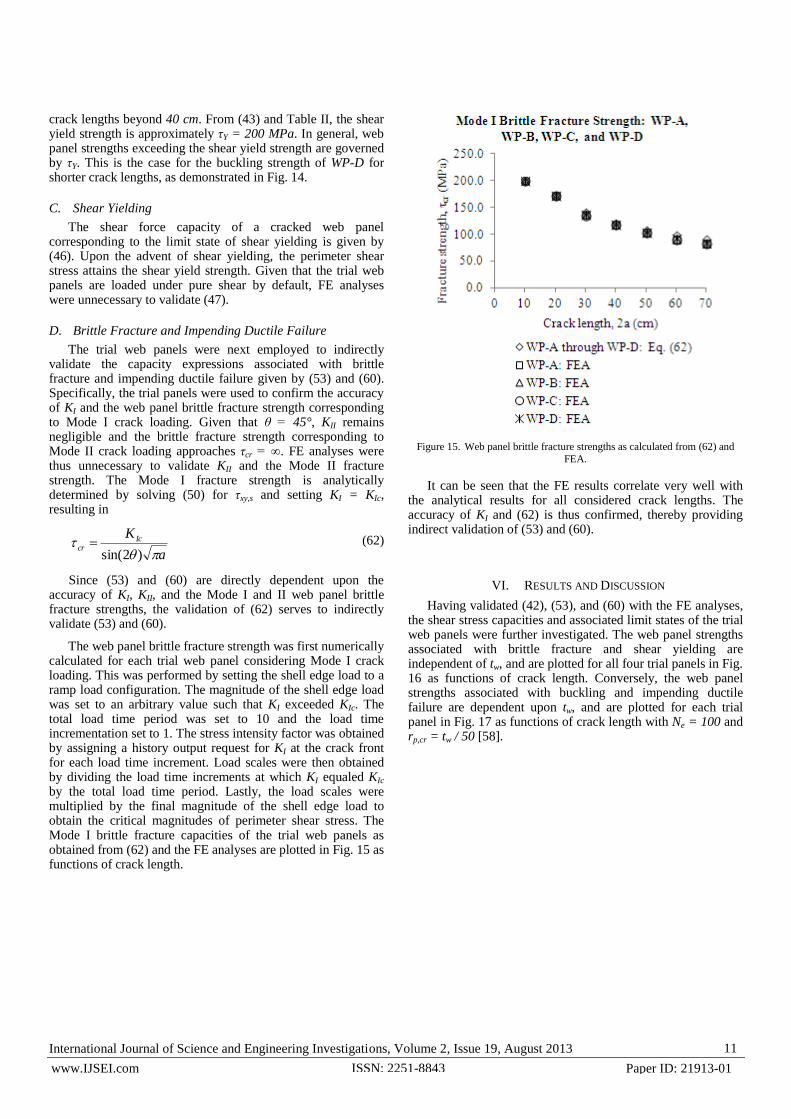
The trial web panels were next employed to indirectly validate the capacity expressions associated with brittle fracture and impending ductile failure given by (53) and (60). Specifically, the trial panels were used to confirm the accuracy of KI and the web panel brittle fracture strength corresponding to Mode I crack loading. Given that θ = 45°, KII remains negligible and the brittle fracture strength corresponding to Mode II crack loading approaches τcr = ∞. FE analyses were thus unnecessary to validate KII and the Mode II fracture strength. The Mode I fracture strength is analytically determined by solving (50) for τxy,s and setting KI = KIc, resulting in
a
K Iccr
)2sin( (62)
Since (53) and (60) are directly dependent upon the accuracy of KI, KII, and the Mode I and II web panel brittle fracture strengths, the validation of (62) serves to indirectly validate (53) and (60).
The web panel brittle fracture strength was first numerically calculated for each trial web panel considering Mode I crack loading. This was performed by setting the shell edge load to a ramp load configuration. The magnitude of the shell edge load was set to an arbitrary value such that KI exceeded KIc. The total load time period was set to 10 and the load time incrementation set to 1. The stress intensity factor was obtained by assigning a history output request for KI at the crack front for each load time increment. Load scales were then obtained by dividing the load time increments at which KI equaled KIc by the total load time period. Lastly, the load scales were multiplied by the final magnitude of the shell edge load to obtain the critical magnitudes of perimeter shear stress. The Mode I brittle fracture capacities of the trial web panels as obtained from (62) and the FE analyses are plotted in Fig. 15 as functions of crack length.
Figure 15. Web panel brittle fracture strengths as calculated from (62) and
FEA.
It can be seen that the FE results correlate very well with the analytical results for all considered crack lengths. The accuracy of KI and (62) is thus confirmed, thereby providing indirect validation of (53) and (60).
VI. RESULTS AND DISCUSSION
Having validated (42), (53), and (60) with the FE analyses, the shear stress capacities and associated limit states of the trial web panels were further investigated. The web panel strengths associated with brittle fracture and shear yielding are independent of tw, and are plotted for all four trial panels in Fig. 16 as functions of crack length. Conversely, the web panel strengths associated with buckling and impending ductile failure are dependent upon tw, and are plotted for each trial panel in Fig. 17 as functions of crack length with Ne = 100 and rp,cr = tw / 50 [58].

International Journal of Science and Engineering Investigations, Volume 2, Issue 19, August 2013 12
www.IJSEI.com Paper ID: 21913-01 ISSN: 2251-8843
Figure 16. Web panel brittle fracture and shear yielding capacities for WP-A
through WP-D.
Figure 17. Web panel buckling and impending ductile failure capacities for
WP-A through WP-D.
The limit states of brittle fracture and shear yielding do not govern the shear stress capacities of any of the trial web panels. Web buckling governs the capacity of WP-A for all considered crack lengths. Also, web buckling governs the capacity of WP-B for crack lengths up to 2a ≈ 19 cm, with impending ductile failure governing thereafter. Similarly, web buckling governs the capacity of WP-C for crack lengths up to 2a ≈ 3 cm, with impending ductile failure governing thereafter. Impending ductile failure governs the capacity of WP-D for all considered crack lengths.
It is noted that although impending ductile failure is a limit state in itself and signifies the invalidation of the brittle fracture limit state, the shear yielding and web buckling limit states may remain valid. With this in mind, it is observed that the web buckling capacities of the trial panels are significantly degraded with increased crack length. The trial panel buckling
International Journal of Science and Engineering Investigations, Volume 2, Issue 19, August 2013 13
www.IJSEI.com Paper ID: 21913-01 ISSN: 2251-8843
strengths are degraded by as much as 30% when the crack length reaches 70 cm.
The applicability of the shear force capacity expressions is finally demonstrated with a simplified plate girder design problem. In this particular example, load and resistance factors are neglected. An I-shaped transversely stiffened plate girder is to be designed to resist predominantly shear forces. The girder is required to have an unfactored shear force capacity of Vs = 381 kN (see Fig. 1). The geometry and material properties of WP-C are initially selected for the design. From (1), the required perimeter shear stress capacity of WP-C is τxy,s = 50 MPa. From Fig. 17, the provided perimeter shear stress capacity of WP-C is τcr = 52 MPa, governed by the limit state of web buckling. Substituting this value into (44) results in the provided shear force capacity of WP-C, given by Vcr = 396 kN. Since Vs = 381 kN < Vcr = 396 kN, the shear force capacity provided by WP-C is sufficient if the girder remains uncracked.
The girder is now required to maintain a sufficient capacity for a prescribed diagonal fatigue crack configuration within a web panel so as to avoid the occurrence of elastic limit states in between bridge inspection periods (see Fig. 2). The prescribed crack length is assumed to be 2a = 50 cm and its angle of inclination is assumed to be θ ≈ 45°. From Fig. 17, the provided perimeter shear stress capacity when 2a = 50 cm is τcr
= 10.7 MPa, governed by the limit state of impending ductile failure. However, neglecting impending ductile failure and considering only the web buckling limit state results in a provided perimeter shear stress capacity of τcr = 41.3 MPa. Substituting this value into (44) results in the provided shear force capacity of WP-C when 2a = 50 cm, given by Vcr = 315 kN. Since Vs = 381 kN > Vcr = 315 kN, the shear strength provided by WP-C is insufficient for the prescribed crack configuration. Increasing the web panel thickness of WP-C from tw = 0.6 cm to tw = 0.7 cm and employing (42) with Ne = 100 results in the modified perimeter shear stress capacity of τcr
= 56.3 MPa. Substituting this value into (44) results in the modified shear force capacity of WP-C when 2a = 50 cm, given by Vcr = 501 kN. Since Vs = 381 kN < Vcr = 501 kN, the shear strength provided by WP-C with tw = 0.7 cm is sufficient for the prescribed crack configuration. It is noted that this design method of trial-and-error may be applied using load and resistance factors.
VII. CONCLUSIONS
Analytical expressions for the elastic shear force capacity of a cracked web panel corresponding to the limit states of shear yielding of the web, web local buckling, brittle fracture, and impending ductile failure were formulated. The expressions were specific to the case of a through-thickness fatigue crack initiating and propagating from a corner of a web panel at the junction of a flange and transverse stiffener plate with θ ≈ 45°. The expressions were validated with FE analyses and employed to investigate the residual cracked strengths of various web panel geometries. The governing limit states and associated strengths were found to be largely dependent upon the web panel thickness and crack length. Realistically proportioned plate girders were concluded to be governed by
the web buckling limit state with impending ductile failure behaving as a secondary limit state.
Overall, the capacity expressions may be applied in the design and analysis of I-shaped transversely stiffened plate girders loaded under predominantly shear considering prescribed diagonal fatigue crack configurations with θ ≈ 45°. Future work could include the performance of supplementary FE analyses to investigate the influence of the transverse stiffener plate spacings. Also, experimental tests could be performed on full-scale or small-scale pre-cracked plate girders to further validate the analytical expressions. Finally, advanced investigations could be undertaken to develop expressions considering the post-buckling behavior and tension field action of cracked web panels.
REFERENCES
[1] F.P. Beer, E.R. Johnston, and J.T. DeWolf, Mechanics of Materials, 4th ed. New York, NY: McGraw-Hill, 2006, chs. 4, 7, 8.
[2] C.G. Salmon, J.E. Johnson, and F.A. Malhas, Steel Structures: Design and Behavior, 5th ed. Upper Saddle River, NJ: Pearson Prentice Hall, 2009, ch. 2, secs. 6.14, 7.7, 11.7.
[3] R.M. Barker and J.A. Puckett, Design of Highway Bridges. New York, NY: John Wiley & Sons, 1997.
[4] R. Crocetti, “Web breathing of full-scale slender I-girders subjected to combined action of bending and shear,” J. of Construct. Steel Research, vol. 59, no. 3, pp. 271-290, 2003.
[5] S.T. Rolfe and J.M. Barsom, Fracture and Fatigue Control in Structures: Applications of Fracture Mechanics. Englewood Cliffs, NJ: Prentice-Hall, 1977
[6] B. Lawn, Fracture of Brittle Solids, 2nd ed, E.A. Davis and I.M. Ward, Eds. Cambridge, UK: Cambridge University Press, 1993.
[7] S.A. Meguid, Engineering Fracture Mechanics. New York, NY: Elsevier Science Publishing Co., Inc, 1989, ch. 7.
[8] C.T. Sun and Z.-H. Jin, Fracture Mechanics. Waltham, MA: Academic Press, 2012, chs. 3, 5.
[9] N.G. Kouba and J.E. Stallmeyer, J.E., “The behavior of stiffened beams under repeated loads,” University of Illinois, Urbana, IL, Structural Research Series No. 173, 1959.
[10] B.T. Yen, “On the fatigue strength of welded plate girders,” Lehigh University, Bethlehem, PA, Fritz Engrg. Lab. Rep. No. 303-1, 1963.
[11] L.R. Hall and J.E. Stallmeyer, “Thin web girder fatigue behavior as influenced by boundary rigidity,” University of Illinois, Urbana, IL, Structural Research Series No. 278, 1964.
[12] D.W. Goodpasture and J.E. Stallmeyer, “Fatigue behavior of welded thin web girders as influenced by web distortion and boundary rigidity,” University of Illinois, Urbana, IL, Structural Research Series No. 328, 1967.
[13] B.T. Yen and J.A. Mueller, “Fatigue tests of large-size welded plate girders,” Lehigh University, Bethlehem, PA, Fritz Engrg. Lab. Rep. No. 303-10, 1966.
[14] J.A. Mueller and B.T. Yen, “Girder web boundary stresses and fatigue,” Lehigh University, Bethlehem, PA, Fritz Engrg. Lab. Rep. No. 327-2, 1967.
[15] P.C. Paris and F. Erdogan, “A critical analysis of crack propagation laws,” J. of Basic Engrg., vol. 85, no. 4, pp. 528-534, 1963.
[16] B. Kirke and I.H. Al-Jamel, Steel Structures Design Manual to AS 4100. Author, 2004, sec. 2.3.3.
[17] Lichtenstein, Special Inspections of Selected Portions of The Providence Viaduct, Route I-95 from West Exchange Street to Promenade Street, Bridge No. 578 (Supplemental Report for Project No. 1213). Framingham, MA: A.G. Lichtenstein and Associates, Inc, 1990.

International Journal of Science and Engineering Investigations, Volume 2, Issue 19, August 2013 14
www.IJSEI.com Paper ID: 21913-01 ISSN: 2251-8843
[18] J. Minor and C. Woodward, “Web buckle at I-40 bridge test,” J. Bridge Engrg., vol. 1, no. 1, pp. 34-36, 1996.
[19] M. Chajes, D. Mertz, S. Quiel, H. Roecker, and J. Milius, “Steel girder fracture on Delaware’s I-95 bridge over the Brandywine River,” in Proc. Structures Congress 2005.
[20] M.D. Bowman, “Brittle fracture of the Blue River Bridge,” in Proc. Structures Congress 2004.
[21] Y.E. Zhou and A.E. Biegalski, “Investigation of large web fractures of welded steel plate girder bridge,” J. Bridge Engrg., vol. 15, no. 4, pp. 373-383, 2010.
[22] K. Wardhana and F.C. Hadipriono, “Analysis of recent bridge failures in the United States,” J. Performance of Constructed Facilities, vol. 17, no. 3, pp. 144-150, 2003.
[23] A. Vafai and H.E. Estekanchi, “A parametric finite element study of cracked plates and shells,” Thin-Walled Struct., vol. 33, no. 3, pp. 211-229, 1999.
[24] Y.V.S. Kumar and J.K. Paik, “Buckling analysis of cracked plates using hierarchical trigonometric functions,” Thin-Walled Struct., vol. 42, no. 5, pp. 687-700, 2004.
[25] J.K. Paik, J.K., Y.V.S. Kumar, and J.M. Lee, “Ultimate strength of cracked plate elements under axial compression or tension,” Thin-Walled Struct., vol. 43, no. 2, pp. 237-272, 2005.
[26] R. Brighenti, “Buckling of cracked thin-plates under tension or compression,” Thin-Walled Struct., vol. 43, no. 2, pp. 209-224, 2005.
[27] R. Brighenti, “Numerical buckling analysis of compressed or tension cracked thin plates,” Engrg. Struct., vol. 27, no. 2, pp. 265-276, 2005.
[28] R. Brighenti, “Buckling sensitivity analysis of cracked thin plates under membrane tension or compression loading,” Nuclear Engrg. and Design, vol. 239, no. 6, pp. 965-980, 2009.
[29] M.R. Khedmati, P. Edalat, and M. Javidruzi, “Sensitivity analysis of the elastic buckling of cracked plate elements under axial compression,” Thin-Walled Struct., vol. 47, no. 5, pp. 522-536, 2009.
[30] R. Seifi and N. Khoda-yari, “Experimental and numerical studies on buckling of cracked thin-plates under full and partial compression edge loading,” Thin-Walled Struct., vol. 49, no. 12, pp. 1504-1516, 2011.
[31] M.M. Alinia, S.A.A. Hosseinzadeh, and H.R. Habashi, “Buckling and post-buckling strength of shear panels degraded by near border cracks,” J. Construct. Steel Research, vol. 64, no. 12, pp. 1483-1494, 2007.
[32] M.M. Alinia, S.A.A. Hosseinzadeh, and H.R. Habashi, “Influence of central cracks on buckling and post-buckling behaviour of shear panels,” Thin-Walled Struct., vol. 45, no. 4, pp. 422-431, 2007.
[33] M.M. Alinia, S.A.A. Hosseinzadeh, and H.R. Habashi, “Numerical modelling for buckling analysis of cracked shear panels,” Thin-Walled Struct., vol. 45, no. 12, pp. 1058-1067, 2007.
[34] R. Brighenti and A. Carpinteri, “Buckling and fracture behaviour of cracked thin plates under shear loading,” Materials and Design, vol. 32, no. 3, pp. 1347-1355, 2011.
[35] A.N. Guz and M.Sh. Dyshel, “Fracture and buckling of thin panels with edge crack in tension,” Theo. and Appl. Fract. Mech., vol. 36, no. 1, pp. 57-60, 2001.
[36] A.N. Guz and M.Sh. Dyshel, “Stability and residual strength of panels with straight and curved cracks,” Theo. and Appl. Fract. Mech., vol. 31, nos. 1-3, pp. 95-101, 2004.
[37] R. Roberts, J.W. Fisher, G.R. Irwin, K.D. Boyer, G.V. Hausammann, V. Krishna, R. Morf, and R.E. Slockbower, “Determination of tolerable flaw sizes in full size welded bridge details,” Lehigh University, Bethlehem, PA, Fritz Engrg. Lab. Rep. No. 399-3, 1977.
[38] T.M. Roberts, M.H. Osman, M. Skaloud, and M. Zornerova, “Residual shear strength of fatigue cracked slender web panels,” Thin-Walled Struct., vol. 24, no. 2, pp. 157-172, 1996.
[39] P.B. Cooper and J. Roychowdhury, “Shear strength of plate girders with web openings,” J. Struct. Engrg., vol. 116, no. 7, pp. 2042-2048, 1990.
[40] R. Narayanan and N. Der-Avanessian, “Design of slender webs having rectangular holes,” J. Struct. Engrg., vol. 111, no. 4, pp. 777-787, 1985.
[41] J. Cheng and J. Yura, “Local web buckling of coped beams,” J. Struct. Engrg., vol. 112, no. 10, pp. 2314-2331, 1986.
[42] M. Ito, K. Fujiwara, and K. Okazaki, “Ultimate strength of beams with U-shaped holes in top of web,” J. Struct. Engrg., vol. 117, no. 7, pp. 1929-1945, 1991.
[43] W. Zaarour and R. Redwood, “Web buckling in thin webbed castellated beams,” J. Struct. Engrg., vol. 122, no. 8, pp. 860-866, 1996.
[44] R. Redwood and S. Demirdjian, “Castellated beam web buckling in shear,” J. Struct. Engrg., vol. 124, no. 10, pp. 1202-1207, 1998.
[45] N.E. Shanmugam, V.T. Lian, and V. Thevendran, “Finite element modelling of plate girders with web openings,” Thin-Walled Struct., vol. 40, no. 5, pp. 443-464, 2002.
[46] N.C. Hagen, P.K. Larsen, and A. Aalberg, “Shear capacity of steel plate girders with large web openings, part I: Modeling and simulations,” J. Construct. Steel Research, vol. 65, no. 1, pp. 142-150, 2009.
[47] N.C. Hagen and P.K. Larsen, “Shear capacity of steel plate girders with large web openings part II: Design guidelines,” J. Construct. Steel Research, vol. 65, no. 1, pp. 151-158, 2009.
[48] O. Bedair, “Stress analyses of deep plate girders used at oil and gas facilities with rectangular web penetrations,” Practice Periodical on Struct. Design and Construct., vol. 16, no. 3, pp. 112-120, 2011.
[49] H. Wagner, H, “Flat sheet metal girder with very thin metal web,” National Advisory Committee for Aeronautics, Hampton, VA, Tech Memorandum Nos. 604-606, 1931.
[50] T. Fujii, “On an improved theory for Dr. Basler’s theory,” Proceedings of the 8th Congress IABSE. New York, NY: International Association for Bridge and Structural Engineering, pp. 479-487, 1968.
[51] K. Basler and B. Thurlimann, “Strength of plate girders in shear,” Lehigh University, Bethlehem, PA, Fritz Egrg. Lab. Rep. No. 251-20, 1960.
[52] M.H. Sadd, Elasticity: Theory, Applications, and Numerics, 2nd ed. Burlington, MA: Academic Press, 2009, ch. 7, sec. 4.1
[53] J.R. Vinson, Structural Mechanics: The Behavior of Plates and Shells. New York, NY: John Wiley & Sons, Inc., 1974, ch. 5, sec. 6.1.
[54] H.M. Westergaard, “Bearing pressures and cracks,” J. Applied Mech., vol. 6, no. 61, pp. 49-53, 1939.
[55] L.I. Sedov, A Course in Continuum Mechanics, J.R.M. Radok, Trans. Groningen, Netherlands: Wolters-Noordhoff Publishing, 1972, sec. 13.2.8.
[56] T. Fett, Stress Intensity Factors, T-Stresses, Weight Functions. Karlsruhe, Germany: Universitätsverlag Karlsruhe, 2008.
[57] S.A. Meguid, Engineering Fracture Mechanics. New York, NY: Elsevier Science Publishing Co., Inc, 1989, chs. 3, 5, 6.
[58] A. Shukla, Practical Fracture Mechanics in Design, 2nd ed. New York, NY: Marcel Dekker, 2005, chs. 2-4.
Sebastian B. Mendes is a Doctoral candidate
at the Department of Civil and Environmental
Engineering, University of Rhode Island,
Kingston, RI. He earned the B.Sc. degree in
civil engineering from Rose-Hulman Institute
of Technology, Terre Haute, IN, in 2009 and
the M.Sc. degree in civil engineering from
Worcester Polytechnic Institute, Worcester,
MA, in 2011. He has previously worked as an
entry-level structural engineer in New Haven, CT, and as a Research
Assistant at Worcester Polytechnic Institute. He entered the
University of Rhode Island in 2011 and is currently performing
research and working as a Teaching Assistant.