Proposed Linac Upgrade with a SLED Cavity at the...
3
PROPESED LINAC UPGRRADE WITH A SLED CAVITY AT THE AUSTRALIAN SYNCHROTRON, SLSA Karl Zingre, Greg LeBlanc, Mark Atkinson, Brad Mountford, Rohan Dowd, SLSA, Clayton, Australia Christoph Hollwich, SPINNER, Westerham, Germany Abstract The Australian Synchrotron Light Source has been operating successfully since 2007 and in top-up mode since 2012, while additionally being gradually upgraded to reach a beam availability exceeding 99 %. Considering the ageing of the equipment, effort is required in order to maintain the reliability at this level. The proposed upgrade of the linac with a SLED cavity has been chosen to mitigate the risks of single point of failure and lack of spare parts. The linac is normally fed from two independent klystrons to reach 100 MeV beam energy, and can be operated in single (SBM) or multi-bunch mode (MBM). The SLED cavity upgrade will allow remote selection of single klystron operation in SBM and possibly limited MBM without degradation of beam energy and reduce down time in case of a klystron failure. The proposal for the SLED cavity upgrade is shown and the linac designs are detailed. INTRODUCTION The injector comprises a 100 MeV linac and a 3 GeV booster to enable full energy beam injection into the storage ring. The injector was upgraded later from decay to top-up mode operation to keep the storage ring at 200 mA current. Top-up has been continually running since then with an MBM injection of 0.5 mA every few minutes compared to a reinjection every 12 hours in decay mode. Alongside top-up came the need to improve reliability and mean down time for the entire facility. Improvements on the injector were more cost effective to target mean down time due to the increase in wear on the system, single point of failure and the limited lifespan of devices such as the electron tubes. Improvements on the linac were necessary with two klystrons required for operation, and a failure could take weeks, depending on missing critical spare parts. The waveguide radio frequency (RF) distribution system for the linac was modified in the first stage in 2010, to test single klystron operation to power the whole linac; albeit at a reduced final beam energy. Booster injection was successful, but booster ramping remained unsolved as a lack of control in fine field adjustments at low energy levels from below 100 MeV. The increase in klystron trips operating at higher power levels was also not satisfactory. The next stage is to add a SLED cavity to overcome the current deficiencies. This paper will outline the proposed upgrade and benefits. LINAC OVERVIEW General Specifications The 100 MeV 3 GHz linac structure is made of a 90 keV thermionic electron gun (GUN), a 500 MHz subharmonic prebuncher unit (SPB), preliminimary buncher (PBU), final buncher (FBU), and two 5 m accelerating structures. The structures are powered by two 35 MW pulsed klystrons supplied from a pulse forming network (PFN). The low level electronics include two pulsed 400W S band amplifiers to drive the klystrons, and two 500W UHF amplifiers for the GUN and SPB. The linac is based on the SLS/DLS design and was delivered by Research Instruments, formerly ACCEL, the modulators subcontracted to PPT-Ampegon, and the waveguide to SPINNER. The linac overview is shown in Figure 1, a summary of the general specifications listed in Table 1 and more details referenced to [1]. KLYSTRON 1 POS: 00000 KLYSTRON 2 I I I I I I I x6 ACCELERATOR STRUCTURE 2 ACCELERATOR STRUCTURE 1 GUN Pi: 000 W Pi: 000 W Pi: 000 W Pi: 000 W Pi: 00.0 MW, 000.1° Pr: 00.0 MW, 000.1° FBU PBU POS: 00000 POS: 00000 POS: 00000 POS: 00000 POS: 00000 POS: 00000 POS: 00000 POS: 00000 POS: 00000 Pi: 00.0 MW, 000.1° Pr: 00.0MW, 000.1° Pi: 00.0 MW, 000.1° Pr: 00.0 MW, 000.1° Pi: 00.0 MW, 000.1° Pr: 00.0 MW, 000.1° Pi: 00.0 MW, 000.1° Pr: 00.0 MW, 000.1° Pi: 0.00 MW, 000.0° Pr: 0.00 MW, 000.0° Pi: 000 W, 000.1° Pr: 000 W, 000.1° Pi: 0.00 MW, 000.0° Pr: 0.00 MW, 000.0° CU 9015 FO PPA 10 ± 400 BN PPA 69 ± 500 FO PPA 69 ± 500 FO PPA 10 ± 400 BN WR 284 RF DISTRIBUTION SYSTEM SPU A B A B 500 MHz MO LI-RF-AMP-04 LI-RF-AMP-03 LI-RF-AMP-01 LI-RF-AMP-02 LEGEND: pulse modulator I phase shifter var. power splitter (hybrid) isolator amplifier coupler power splitter LCW SF6 Thermostat Vacuum PSS Main switch 415VAC Emergency Solenoid P/S Interlock Status M M M Figure 1: Linac overview. Table 1: Linac Specifications Quantity Specification Beam Energy 100 MeV RF Frequency 2.997 GHz Repetition rate 1 Hz RMS Emittance 50 ʌ mm mrad Single/Multi-bunch pulse length 2/150 ns Single/Multi-bunch pulse charge > 0.5/4 nC RF Distribution The RF power from the two klystrons is transmitted and distributed across the SF6 pressurised WR284 waveguide distribution system. The first klystron feeds power to the PBU, FBU and first accelerating structure, with two successive variable power dividers used to distribute the correct amount of power to each section. The second klystron feeds the power to the second WEPMA001 Proceedings of IPAC2015, Richmond, VA, USA ISBN 978-3-95450-168-7 2738 Copyright © 2015CC-BY-3.0 and by the respective authors 7: Accelerator Technology T08 - RF Power Sources
Transcript of Proposed Linac Upgrade with a SLED Cavity at the...
PROPESED LINAC UPGRRADE WITH A SLED CAVITY AT THE AUSTRALIAN SYNCHROTRON, SLSA
Karl Zingre, Greg LeBlanc, Mark Atkinson, Brad Mountford, Rohan Dowd, SLSA, Clayton, AustraliaChristoph Hollwich, SPINNER, Westerham, Germany
Abstract The Australian Synchrotron Light Source has been
operating successfully since 2007 and in top-up mode since 2012, while additionally being gradually upgraded to reach a beam availability exceeding 99 %. Considering the ageing of the equipment, effort is required in order to maintain the reliability at this level. The proposed upgrade of the linac with a SLED cavity has been chosen to mitigate the risks of single point of failure and lack of spare parts. The linac is normally fed from two independent klystrons to reach 100 MeV beam energy, and can be operated in single (SBM) or multi-bunch mode (MBM). The SLED cavity upgrade will allow remote selection of single klystron operation in SBM and possibly limited MBM without degradation of beam energy and reduce down time in case of a klystron failure. The proposal for the SLED cavity upgrade is shown and the linac designs are detailed.
INTRODUCTION The injector comprises a 100 MeV linac and a 3 GeV
booster to enable full energy beam injection into the storage ring. The injector was upgraded later from decay to top-up mode operation to keep the storage ring at 200 mA current. Top-up has been continually running since then with an MBM injection of 0.5 mA every few minutes compared to a reinjection every 12 hours in decay mode.
Alongside top-up came the need to improve reliability and mean down time for the entire facility. Improvements on the injector were more cost effective to target mean down time due to the increase in wear on the system, single point of failure and the limited lifespan of devices such as the electron tubes. Improvements on the linac were necessary with two klystrons required for operation, and a failure could take weeks, depending on missing critical spare parts. The waveguide radio frequency (RF) distribution system for the linac was modified in the first stage in 2010, to test single klystron operation to power the whole linac; albeit at a reduced final beam energy. Booster injection was successful, but booster ramping remained unsolved as a lack of control in fine field adjustments at low energy levels from below 100 MeV. The increase in klystron trips operating at higher power levels was also not satisfactory. The next stage is to add a SLED cavity to overcome the current deficiencies. This paper will outline the proposed upgrade and benefits.
LINAC OVERVIEW
General Specifications The 100 MeV 3 GHz linac structure is made of a
90 keV thermionic electron gun (GUN), a 500 MHz subharmonic prebuncher unit (SPB), preliminimary buncher (PBU), final buncher (FBU), and two 5 m accelerating structures. The structures are powered by two 35 MW pulsed klystrons supplied from a pulse forming network (PFN). The low level electronics include two pulsed 400W S band amplifiers to drive the klystrons, and two 500W UHF amplifiers for the GUN and SPB. The linac is based on the SLS/DLS design and was delivered by Research Instruments, formerly ACCEL, the modulators subcontracted to PPT-Ampegon, and the waveguide to SPINNER. The linac overview is shown in Figure 1, a summary of the general specifications listed in Table 1 and more details referenced to [1].
KLYSTRON 1
POS: 00000
KLYSTRON 2
x6
ACCELERATOR STRUCTURE 2 ACCELERATOR STRUCTURE 1
GUN
Pi: 000 W
Pi: 000 W
Pi: 000 W
Pi: 000 W
Pi: 00.0 MW, 000.1°
Pr: 00.0 MW, 000.1°
FBU PBU
POS: 00000
POS: 00000
POS: 00000
POS: 00000
POS: 00000
POS: 00000 POS: 00000
POS: 00000
POS: 00000
Pi: 00.0 MW, 000.1°
Pr: 00.0MW, 000.1°
Pi: 00.0 MW, 000.1°
Pr: 00.0 MW, 000.1°
Pi: 00.0 MW, 000.1°
Pr: 00.0 MW, 000.1°
Pi: 00.0 MW, 000.1°
Pr: 00.0 MW, 000.1°
Pi: 0.00 MW, 000.0°
Pr: 0.00 MW, 000.0°
Pi: 000 W, 000.1°
Pr: 000 W, 000.1°
Pi: 0.00 MW, 000.0°
Pr: 0.00 MW, 000.0°
CU 9015 FO
PPA 10 400 BN PPA 69 500 FO
PPA 69 500 FOPPA 10 400 BN
WR 284 RF
DISTRIBUTION
SYSTEM
SPU
A
B A
B
500 MHz MO
LI-RF-AMP-04
LI-RF-AMP-03
LI-RF-AMP-01
LI-RF-AMP-02
LEGEND: pulse modulator phase shiftervar. power splitter
(hybrid)isolator amplifier coupler power splitter
LCW
SF6
Thermostat
Vacuum
PSS Main switch 415VAC
Emergency Solenoid P/S
Interlock Status
M
M
M
Figure 1: Linac overview.
Table 1: Linac Specifications
Quantity Specification Beam Energy 100 MeV RF Frequency 2.997 GHz Repetition rate 1 Hz RMS Emittance 50 mm mrad Single/Multi-bunch pulse length 2/150 ns Single/Multi-bunch pulse charge > 0.5/4 nC
RF Distribution The RF power from the two klystrons is transmitted
and distributed across the SF6 pressurised WR284 waveguide distribution system. The first klystron feeds power to the PBU, FBU and first accelerating structure, with two successive variable power dividers used to distribute the correct amount of power to each section. The second klystron feeds the power to the second
WEPMA001 Proceedings of IPAC2015, Richmond, VA, USA
ISBN 978-3-95450-168-72738Co
pyrig
ht©
2015
CC-B
Y-3.
0an
dby
ther
espe
ctiv
eaut
hors
7: Accelerator TechnologyT08 - RF Power Sources

accelerating structure or can be redirected to power the entire linac after the first stage waveguide upgrade to include an additional power splitter and a phase shifter as shown in Figure 1.
The RF phases relative to the other accelerating sections can be individually adjusted in combination with the low level electronic. Phase stability is maintained by temperature control of the waveguide and can be manually readjusted with help from the in-house developed I/Q demodulator power and phase monitoring system installed in 2012. The upgrade of the timing system [2] with an event system in 2009 could further improve injection efficiency and operation due to better jitter performance, resolution and functionality.
SLED CAVITY An RF pulse compression system can enhance the peak
power output from a microwave tube by trading reduced pulse width for increased peak power. A pulse compression system always involves an energy storage element of some sort to delay or transfer energy from the early portion of the RF pulse into the compressed output pulse. The first large-scale pulse compression system for an accelerator application was the Stanford Linac Energy Doubler (SLED) scheme, implemented on the SLAC
3]. SLED is using a pair of TE015 cylindrical high Q cavities (Q0 1x10⁵) as energy storage elements in combination with a 3 dB 90 hybrid coupler. A 180° phase reversal in the klystron drive after charging the cavities will release the stored energy, and the hybrid directs the power from the klystron and the emitted power from the cavity pair all into the transmission line to the accelerator. The compressed SLED output pulse can theoretically multiply the power by a factor of 9. The output power exponentially decays during the discharge in ~1 μs but this is sufficient to fill the accelerating structures and inject limited bunch trains.
Figure 2 shows the typical layout of a SLED with the two cavities, a hybrid and two ion pumps attached.
Figure 2: SLED cavity layout.
The achievable power levels, by the SLED cavity and the resulting effective accelerator gradient, i.e. beam energy to achieve 100 MeV electron beam energy in our case, can be calculated by following the methodology explained in reference [3]. The important factors and
variables for system optimisation, not exceeding any hardware limitations, are the cavity coupling coefficient
accelerating structure filling time Ta. Figure 3 illustrates the simulation of small current
energy gain (red) and the SLED output power pulse shape (blue) depending on beta, the cavity charging time and Ta set at 720 ns.
Figure 3: Effective accelerating gradient.
A smaller beta as expected flattens the pulse shape and reduces peak power while a longer charging time can bust the energy. The next two simulations in Figure 4 show the maximum energy multiplication factor, required klystron power and peak power depending on Beta.
Figure 4: Beta optimisation.
A decision was made to set Beta between 3.5-4 and a charging time of 3 μs for the following practical reasons:
Maximum power to be limited to 20 MW klystron power and 100 MW SLED peak output power to mitigate the risk of arcing.
4.5 μs RF pulse length to provide best flat topped pulse depending on the PFN.
Fine tuning will be postponed until commissioning, aiming to minimise the energy change during injection and to test the maximum possible MBM up to 150 ns. The start of injection will be somewhere slightly before the small current energy gain peak to compensate for beam loading.
PROPOSED SLED CAVITY UPGRADE Upgrades commonly involve compromises while
aiming to maintain most of the existing infrastructure to reduce costs. An acceptable solution had to be found as well in this regard to integrate the SLED cavity, operating
Proceedings of IPAC2015, Richmond, VA, USA WEPMA001
7: Accelerator TechnologyT08 - RF Power Sources
ISBN 978-3-95450-168-72739 Co
pyrig
ht©
2015
CC-B
Y-3.
0an
dby
ther
espe
ctiv
eaut
hors
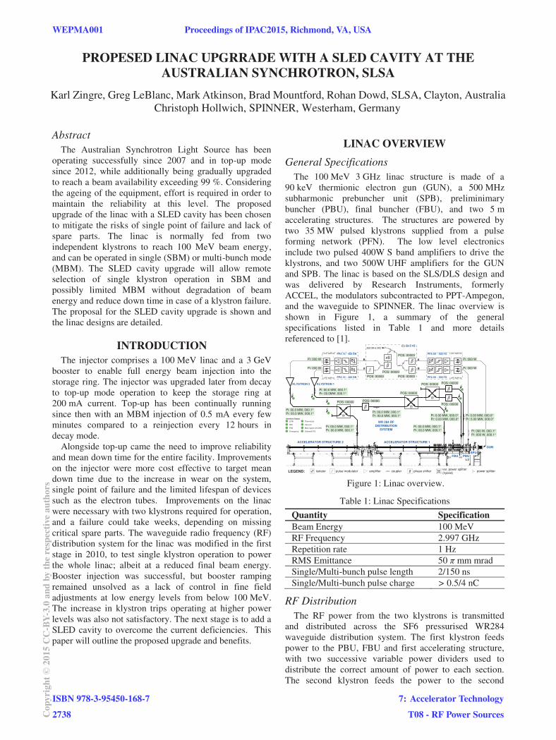
under vacuum, and a switch while maintaining the existing waveguide distribution system pressurised under SF6. Commercially available high pressure windows to separate vacuum, are on the other hand limited to approximately 40 MWp for a few microseconds and would likely break if placed directly at the SLED output. The result for the proposed solution is shown in Figure 5.
KLY1
M
M
VPS I
PS I
M
P
IPIP
SLED Cavity
M
MM
VPS II
VPS III PS II
PS III
PBUFBUACC1
Gun Test Stand (later)
ACC2
P
VPS IV
KLY2
IP
IP
All WGD SF6 filled except SLED
cavity, VPS I and to ACC2
40 MWp
BN768834
80 MWp
80 MWp
80 MWp
100 MWp*
BN 768837
40 MWp
45 MWp 40 MWp
35 MWp 35 MWp
13 MWp 15 MWp 0.7 MWp
8 /9 15 cell
buncher structure
2 /3
buncher structure
S Band 155 cell
accelerating structure
S Band 155 cell
accelerating structure
50 MWp
TBL284
C004 1.5 MWp
TBL28
4C004TH2100TH2100
BN 769923 3020-02 40 MWp
IPIP IP IP
M
MM
BN 268395 rf window
directional
coupler 60 dB
Figure 5: Sled cavity upgrade.
To begin, the SLED cavity had to be placed before the variable power splitter VPS1 to power the entire linac,
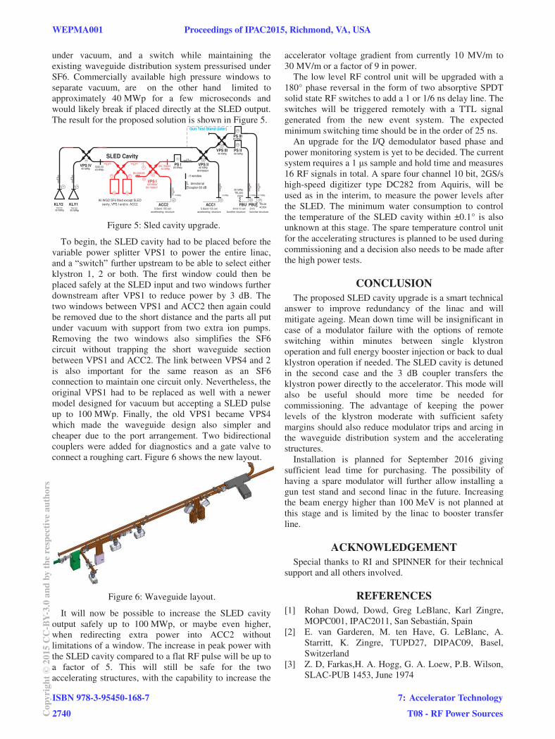
klystron 1, 2 or both. The first window could then be placed safely at the SLED input and two windows further downstream after VPS1 to reduce power by 3 dB. The two windows between VPS1 and ACC2 then again could be removed due to the short distance and the parts all put under vacuum with support from two extra ion pumps. Removing the two windows also simplifies the SF6 circuit without trapping the short waveguide section between VPS1 and ACC2. The link between VPS4 and 2 is also important for the same reason as an SF6 connection to maintain one circuit only. Nevertheless, the original VPS1 had to be replaced as well with a newer model designed for vacuum but accepting a SLED pulse up to 100 MWp. Finally, the old VPS1 became VPS4 which made the waveguide design also simpler and cheaper due to the port arrangement. Two bidirectional couplers were added for diagnostics and a gate valve to connect a roughing cart. Figure 6 shows the new layout.
Figure 6: Waveguide layout.
It will now be possible to increase the SLED cavity output safely up to 100 MWp, or maybe even higher, when redirecting extra power into ACC2 without limitations of a window. The increase in peak power with the SLED cavity compared to a flat RF pulse will be up to a factor of 5. This will still be safe for the two accelerating structures, with the capability to increase the
accelerator voltage gradient from currently 10 MV/m to 30 MV/m or a factor of 9 in power.
The low level RF control unit will be upgraded with a 180° phase reversal in the form of two absorptive SPDT solid state RF switches to add a 1 or 1/6 ns delay line. The switches will be triggered remotely with a TTL signal generated from the new event system. The expected minimum switching time should be in the order of 25 ns.
An upgrade for the I/Q demodulator based phase and power monitoring system is yet to be decided. The current system requires a 1 s sample and hold time and measures 16 RF signals in total. A spare four channel 10 bit, 2GS/s high-speed digitizer type DC282 from Aquiris, will be used as in the interim, to measure the power levels after the SLED. The minimum water consumption to control the temperature of the SLED cavity within ±0.1° is also unknown at this stage. The spare temperature control unit for the accelerating structures is planned to be used during commissioning and a decision also needs to be made after the high power tests.
CONCLUSION The proposed SLED cavity upgrade is a smart technical
answer to improve redundancy of the linac and will mitigate ageing. Mean down time will be insignificant in case of a modulator failure with the options of remote switching within minutes between single klystron operation and full energy booster injection or back to dual klystron operation if needed. The SLED cavity is detuned in the second case and the 3 dB coupler transfers the klystron power directly to the accelerator. This mode will also be useful should more time be needed for commissioning. The advantage of keeping the power levels of the klystron moderate with sufficient safety margins should also reduce modulator trips and arcing in the waveguide distribution system and the accelerating structures.
Installation is planned for September 2016 giving sufficient lead time for purchasing. The possibility of having a spare modulator will further allow installing a gun test stand and second linac in the future. Increasing the beam energy higher than 100 MeV is not planned at this stage and is limited by the linac to booster transfer line.
ACKNOWLEDGEMENT Special thanks to RI and SPINNER for their technical
support and all others involved.
REFERENCES [1] Rohan Dowd, Dowd, Greg LeBlanc, Karl Zingre,
MOPC001, IPAC2011, San Sebastián, Spain [2] E. van Garderen, M. ten Have, G. LeBlanc, A.
Starritt, K. Zingre, TUPD27, DIPAC09, Basel, Switzerland
[3] Z. D, Farkas,H. A. Hogg, G. A. Loew, P.B. Wilson, SLAC-PUB 1453, June 1974
WEPMA001 Proceedings of IPAC2015, Richmond, VA, USA
ISBN 978-3-95450-168-72740Co
pyrig
ht©
2015
CC-B
Y-3.
0an
dby
ther
espe
ctiv
eaut
hors
7: Accelerator TechnologyT08 - RF Power Sources