Proposal of a machining features recognition method for 5 ...
13
Bulletin of the JSME Journal of Advanced Mechanical Design, Systems, and Manufacturing Vol.14, No.7, 2020 © 2020 The Japan Society of Mechanical Engineers [DOI: 10.1299/jamdsm.2020jamdsm0108] Paper No.20-00347 Proposal of a machining features recognition method for 5-axis index milling on multi-tasking machine tools Yuto WATANABE* and Keiichi NAKAMOTO* 1. Introduction Complex shapes machining is required in present manufacturing industry, and there is always strong impetus to improve the efficiency of machining process. Thus, multi-tasking machine tools that can deal with several kinds of machining methods including turning and 5-axis control milling are attracted to achieve highly efficient machining in recent years. However, the machining process is generally complicated and the preparatory time becomes longer because there are a lot of available machining methods and the operational parameters such as the tool posture. Therefore, a computer aided process planning (CAPP) system is indispensable to reduce the efforts for the preparation and to improve the efficiency of machining process on multi-tasking machine tools. In particular, it is well known that 5-axis index milling is an effective machining method on the multi-tasking machine tools and is suitable to machine complex product shapes. In 5-axis index milling, the tool posture is inclined against a machining surface using two rotary axes, and the problems in 3-axis control milling such as requirement of a long overhang length can be solved. On the other hand, the tool posture determination is still a challenging issue in 5-axis index milling. Thus, Huang and Inui proposed an algorithm for automatically determining the optimal overhang length (Huang and Inui, 2010). In addition, Kaneko et al. proposed a fast estimation method that visualizes both the machinable area and the distribution of the minimum overhang length as a color image for each tool posture candidate (Kaneko et al., 2014). Yamada et al. clarified the tool postures to ensure stable cutting in terms of cutting forces and proposed a *Department of Mechanical Systems Engineering, Tokyo University of Agriculture and Technology 2-24-16 Nakacho, Koganei-shi, Tokyo 184-8588, Japan E-mail: genaf@st,go.tuat.ac.jp Received: 16 July 2020; Revised: 26 October 2020; Accepted: 4 November 2020 Abstract Multi-tasking machine tools that can deal with several kinds of machining methods including turning and 5-axis control milling are attracted to achieve highly efficient machining in recent years. However, the machining process is generally complicated and the preparatory time becomes longer because there are a lot of available machining methods and the operational parameters such as the tool posture. Therefore, a computer aided process planning (CAPP) system is indispensable to reduce the efforts for the preparation and to improve the efficiency of machining process on multi-tasking machine tools. For this purpose, this study aims to propose a novel features recognition method can be applied to process planning of 5-axis index milling that is a characteristic machining method for mechanical parts having complex shapes on multi-tasking machine tools. In this method, machining primitives are obtained by dividing the removal volume, and cylindrical machining primitives for turning are additionally obtained even when the target shape does not have a cylinder part. Then, available combinations of tool postures are prepared for each machining primitive depending on the directions in which the machining primitive can be machined. The tool postures during 5-axis index milling are determined by referring specific information such as the number of tool postures. The machining primitives are divided again in each determined tool posture to recognize machining features in order to remove unmachined volume. Thus, the proposed method could be easily applied to process planning of 5-axis index milling on 5-axis controlled machining centers. The results of case study confirm that process planning of 5-axis index milling on multi- tasking machine tools is effectively realized based on the proposed method. Keywords : Process planning, Multi-tasking machine tool, Machining feature, 5-axis index milling 1
Transcript of Proposal of a machining features recognition method for 5 ...
Bulletin of the JSME
Journal of Advanced Mechanical Design, Systems, and ManufacturingVol.14, No.7, 2020
© 2020 The Japan Society of Mechanical Engineers[DOI: 10.1299/jamdsm.2020jamdsm0108]Paper No.20-00347
Proposal of a machining features recognition method
for 5-axis index milling on multi-tasking machine tools
Yuto WATANABE* and Keiichi NAKAMOTO*
1. Introduction
Complex shapes machining is required in present manufacturing industry, and there is always strong impetus to
improve the efficiency of machining process. Thus, multi-tasking machine tools that can deal with several kinds of
machining methods including turning and 5-axis control milling are attracted to achieve highly efficient machining in
recent years. However, the machining process is generally complicated and the preparatory time becomes longer because
there are a lot of available machining methods and the operational parameters such as the tool posture. Therefore, a
computer aided process planning (CAPP) system is indispensable to reduce the efforts for the preparation and to improve
the efficiency of machining process on multi-tasking machine tools.
In particular, it is well known that 5-axis index milling is an effective machining method on the multi-tasking machine
tools and is suitable to machine complex product shapes. In 5-axis index milling, the tool posture is inclined against a
machining surface using two rotary axes, and the problems in 3-axis control milling such as requirement of a long
overhang length can be solved. On the other hand, the tool posture determination is still a challenging issue in 5-axis
index milling. Thus, Huang and Inui proposed an algorithm for automatically determining the optimal overhang length
(Huang and Inui, 2010). In addition, Kaneko et al. proposed a fast estimation method that visualizes both the machinable
area and the distribution of the minimum overhang length as a color image for each tool posture candidate (Kaneko et
al., 2014). Yamada et al. clarified the tool postures to ensure stable cutting in terms of cutting forces and proposed a
*Department of Mechanical Systems Engineering, Tokyo University of Agriculture and Technology 2-24-16 Nakacho, Koganei-shi, Tokyo 184-8588, Japan
E-mail: genaf@st,go.tuat.ac.jp
Received: 16 July 2020; Revised: 26 October 2020; Accepted: 4 November 2020 Abstract Multi-tasking machine tools that can deal with several kinds of machining methods including turning and 5-axis control milling are attracted to achieve highly efficient machining in recent years. However, the machining process is generally complicated and the preparatory time becomes longer because there are a lot of available machining methods and the operational parameters such as the tool posture. Therefore, a computer aided process planning (CAPP) system is indispensable to reduce the efforts for the preparation and to improve the efficiency of machining process on multi-tasking machine tools. For this purpose, this study aims to propose a novel features recognition method can be applied to process planning of 5-axis index milling that is a characteristic machining method for mechanical parts having complex shapes on multi-tasking machine tools. In this method, machining primitives are obtained by dividing the removal volume, and cylindrical machining primitives for turning are additionally obtained even when the target shape does not have a cylinder part. Then, available combinations of tool postures are prepared for each machining primitive depending on the directions in which the machining primitive can be machined. The tool postures during 5-axis index milling are determined by referring specific information such as the number of tool postures. The machining primitives are divided again in each determined tool posture to recognize machining features in order to remove unmachined volume. Thus, the proposed method could be easily applied to process planning of 5-axis index milling on 5-axis controlled machining centers. The results of case study confirm that process planning of 5-axis index milling on multi-tasking machine tools is effectively realized based on the proposed method.
Keywords : Process planning, Multi-tasking machine tool, Machining feature, 5-axis index milling
1

2© 2020 The Japan Society of Mechanical Engineers[DOI: 10.1299/jamdsm.2020jamdsm0108]
Watanabe and Nakamoto, Journal of Advanced Mechanical Design, Systems, and Manufacturing, Vol.14, No.7 (2020)
calculation method of optimum indexing angle candidates for machining surfaces (Yamada et al., 2007). Though there
are many studies on finishing as mentioned above, there are few studies focusing on roughing by 5-axis index milling.
For example, Yamada proposed a method to derive the tool posture where the cutting removal quantity becomes the
maximum (Yamada et al., 2016). However, a free-form surface was treated as the target shape in the study. Therefore,
this study aims to propose a novel features recognition method can be applied to process planning of 5-axis index milling
of mechanical parts having complex shapes.
In the proposed method, machining primitives are obtained by dividing the removal volume, and the combinations
of tool postures are prepared for each machining primitive depending on the directions in which the machining primitive
can be machined. Moreover, by generating a simplified target shape consisting of some cylinders, cylindrical machining
primitives are newly obtained for turning even when the target shape does not have a cylinder part. The tool postures
during 5-axis index milling are determined by referring specific information such as the number of tool postures. The
machining primitives are divided again in each determined tool posture to recognize machining features in order to
remove unmachined volume. By dividing the machining primitive after determining the tool posture, the number of
machining primitives are appropriately limited to shorten the time for process planning even when a lot of tool posture
candidates exist against a complex shape. Thus, the proposed method could be easily applied to process planning of 5-
axis index milling on 5-axis controlled machining centers. In order to confirm the availability of the proposed method,
case studies are conducted by assuming complex shapes machining. The results confirm that process planning of 5-axis
index milling on multi-tasking machine tools is effectively realized based on the proposed method.
2. Computer aided process planning (CAPP) system
In order to reduce the time for preparing machining process, CAM systems are needed to minimize the effort to
generate NC programs. However, it is necessary to manually determine the operational parameters including machining
features and the machining sequence in commercial CAM systems. Therefore, a computer aided process planning (CAPP)
system is expected to be developed to shorten the preparation time. Feature recognition has been considered as an
important technology in the development of CAPP systems. Machining feature means a characteristic shape pattern that
can identify the specific machining method.
Shi et al. reviewed various studies on feature recognition thoroughly (Shi et al., 2020). Graph-based method is one
of the typical feature recognition methods. The boundary representation of the part is transformed to a graph showing the
topology. This graph is then analyzed to extract subsets of nodes and arcs that match with any predefined template (Li et
al., 2010). Rahmani and Arezoo combined the graph-based method with a rule-based method that recognizes features
based on hints such as the attributes of face patterns (Rahmani and Arezoo, 2007). An artificial neural network is also
one of the promising feature recognition methods. For example, Sunil and Pande proposed a feature recognition method
using unique 12-node vector scheme (Sunil and Pande, 2009). However, in most of studies, machining features are
recognized from a target shape. Machining features should be recognized from removal volume in nature, because the
removal volume changes depending on the workpiece shape. Some researchers have attempted to recognize machining
features from the removal volume. Fu et al. recognize machining features by decomposing the removal volume into
multiple sub-volumes and convert them into a graph to determine the machining details using graph-grammar rules. (Fu
et al., 2013). Nishida and Shirase also recognize machining features by decomposing the removal volume to store and
use machining case data (Nishida and Shirase, 2018). Moreover, in the former studies, 3-axis milling and drilling are
assumed as available machining methods on machine tools in the feature recognition methods. Though there are few
recognition methods proposed for multi-tasking machine tools that can deal with several kinds of machining methods
(Dwijayanti and Aoyama, 2014), 5-axis index milling has not been treated as the targeted machining method.
On the other hand, the authors have also proposed unique machining features and the recognition method (Ueno and
Nakamoto, 2015), and have already developed a CAPP system for multi-tasking machine tools that have special functions
such as chucking switch (Inoue and Nakamoto, 2020). In the recognition method, machining primitives are first acquired
by dividing the removal volume into simple shapes such as a cylinder or a cuboid. Then, boundary faces where the
removal volume and the target shape come into contact are detected. Additionally, the boundary faces are extended to the
inside of the removal volume so that machining primitives are obtained by using the extended boundary faces to divide
the removal volume. Finally, machining features are recognized by allocating a machining sequence to each machining
primitive. Figure 1 shows an example of recognized machining features. It is possible to allocate the machining sequence
2

2© 2020 The Japan Society of Mechanical Engineers[DOI: 10.1299/jamdsm.2020jamdsm0108]
Watanabe and Nakamoto, Journal of Advanced Mechanical Design, Systems, and Manufacturing, Vol.14, No.7 (2020)
by, for example, following the descending order of volume of machining primitives, or their distances from the fixed
area. A machining operation could be determined by enumerating machining methods following the machining sequence.
In addition, machining methods such as turning and milling are assigned to machining features by referencing its shape.
By creating new partial target shapes, the recognition method is adapted to chucking switch of a workpiece between
two confronting turning spindles on a multi-tasking machine tool. Figure 2 shows an example of creating the new partial
target shapes before and after the workpiece chucking switch. A face having the largest circumscribed rectangle area
among faces perpendicular to the center axis of turning spindle is detected as the dividing face to separate both the
workpiece shape and the target shape. Then, the separated workpiece shape at one turning spindle side and the separated
target shape at the other turning spindle side are merged to be treated as a new partial target shape. Machining features
that machined before and after the workpiece chucking switch are recognized at each turning spindle side, respectively.
Recently, 5-axis index milling has been popular on multi-tasking machine tools to improve the efficiency of complex
shapes machining. Therefore, in this study, a novel features recognition method is proposed for realizing process planning
of 5-axis index milling on multi-tasking machine tools. Since machining features are recognized to remove unmachined
volume, the proposed method could be easily applied to 5-axis index milling on 5-axis controlled machining centers.
3. Proposed machining features recognition method
In a novel features recognition method, both workpiece and target shapes are prepared as the input CAD models
created so that Z axis of the CAD coordinates system agrees with the center axis of turning spindle of multi-tasking
machine tools. Then, the tool holders are preliminary prepared to calculate the required overhang length through the
interference check. Simple Modeler (AIKOKU ALPHA Corp.) is used as a CAD software, and the API functions of
Simple Modeler and C# are used to develop a CAPP system based on the proposed features recognition method.
(a) Target and workpiece shapes
Target shape
Workpiece shape
Seq. 1 : Face C
Seq. 2 : Face C Seq. 3 : Step
Seq. 4 : Open slot
Seq. 5 : Step + Boss
P
Seq. 6 : Pocket hole
Seq. 7 : Through hole
Seq. 8 : Pocket hole
Seq. 9 : Pocket hole
Seq. 10 : Closed pocket
Seq. 11 : Closed pocket
(b) Machining sequences and recognized machining
features
Workpiece
shape
Target shape
Dividing face
Faces perpendicular to
center axis of turning spindle
Separated target shape
Separated workpiece shape
New partial target shapes
Center axis of turning spindle
Fig. 1 Example of recognized machining features in the author’s previous study (Inoue and Nakamoto, 2020).
Machining features are recognized by allocating a machining sequence to each machining primitive that
is acquired by dividing the removal volume into simple shapes such as a cylinder or a cuboid.
Fig. 2 Example of creating new partial target shapes before and after workpiece chucking switch. (Inoue and
Nakamoto, 2020). A face having the largest circumscribed rectangle area is detected as the dividing face.
Then, the separated workpiece shape at one turning spindle side and the separated target shape at the other
turning spindle side are merged to be treated as a new partial target shape.
3

2© 2020 The Japan Society of Mechanical Engineers[DOI: 10.1299/jamdsm.2020jamdsm0108]
Watanabe and Nakamoto, Journal of Advanced Mechanical Design, Systems, and Manufacturing, Vol.14, No.7 (2020)
3.1 Obtainment of machining primitives
Machining primitives are obtained by dividing the removal volume, and machining features related to turning are
recognized from only cylindrical machining primitives. However, in the previous study, cylindrical machining primitives
are not obtained and machining features related to turning are not recognized when the target shape does not have a
cylinder part as shown in Fig. 3. Therefore, in this study, cylindrical machining primitives for turning are obtained
regardless of the target shape in order to increase the flexibility of machining process on multi-tasking machine tools.
Figure 4(a) shows an example of target shape. The target shape is firstly divided by planes including target shape’s
faces perpendicular to the center axis of turning spindle as shown in Fig. 4(b). Then, the smallest cylinders that contain
each divided shape are created so that the center axis agrees with the turning spindle as shown in Fig. 4(c). The original
target shape is simplified by combining these created cylinders as shown in Fig. 4(d). By using the simplified target shape
and the workpiece shape, additional cylindrical machining primitives are obtained by dividing the removal volume as
shown in Fig. 4(e). The additional cylindrical machining primitives are used in the recognition of machining features
together with machining primitives obtained from the removal volume between the original target shape and the
workpiece shape.
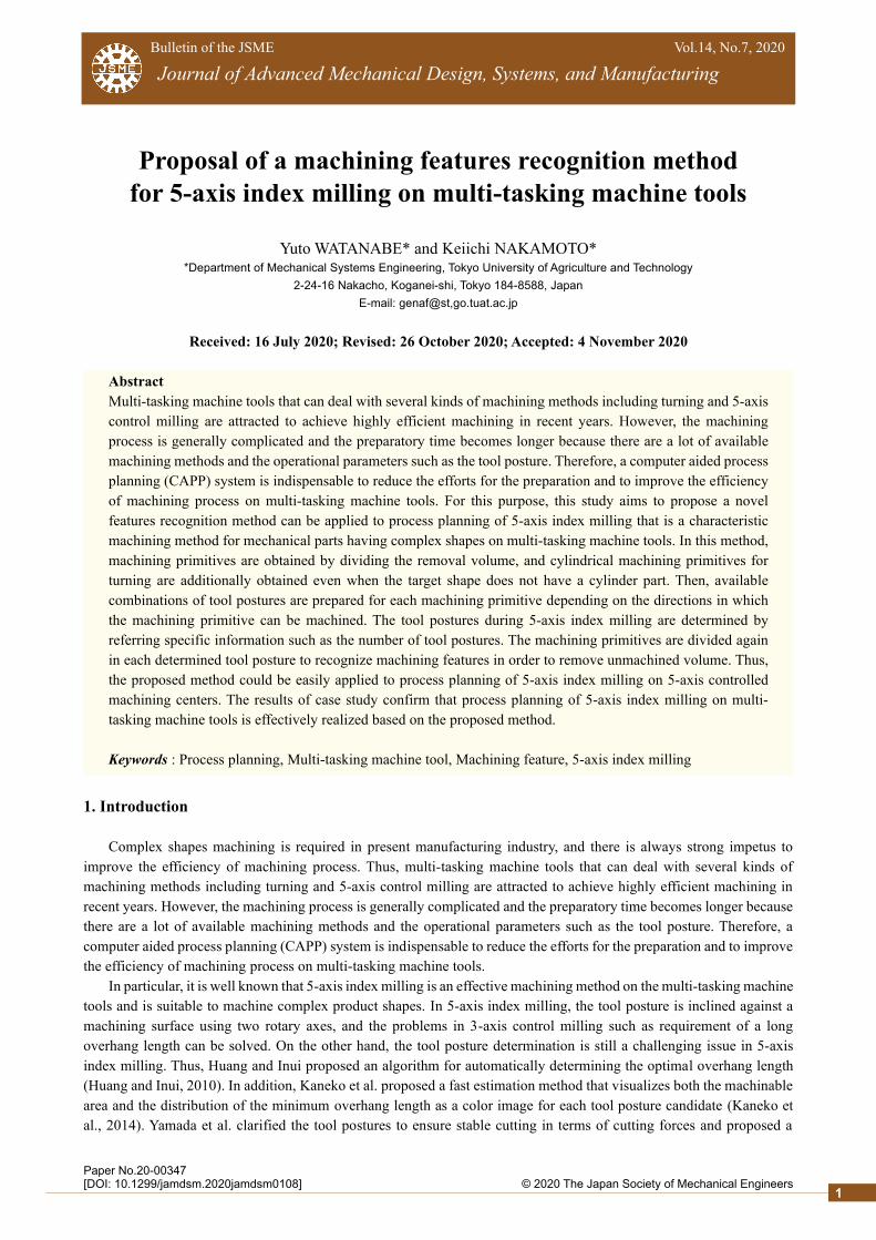
Moreover, a screw thread is also removed and the target shape is approximated before obtaining machining
primitives. The procedure is similar to the approximation of target shape having a chamfer or fillet part proposed in the
previous study. The detected screw theread is removed and the target shape is changed to a simple cylinder as shown in
Fig. 5. Then, the difference between the approximated target shape and the original target shape is treated as a special
machining primitive that the last machining sequence is allocated for tapping.
(a) Detected faces perpendicular to
center axis of turning spindle
(b) Divided target shapes
Center axis of turning spindle
Vertical face
(d) Created simplified target shape
(c) Cylinders containing
each divided target shape
Machining primitive
(e) Obtained additional machining primitives
Obtained machining primitives
Target shape
Workpiece shape Center axis of turning spindle
Fig. 4 Creation of simplified target shape. (a) shows detected target shape’s faces perpendicular to the center
axis of turning spindle axis. (b) shows the target shape divided by planes including each detected face.
(c) shows created cylinders containing each divided target shape. (d) shows the target shape simplified
by combining created cylinders. (e) shows obtained additional machining primitives according to the
simplified target shape.
Fig. 3 Example of machining primitives obtained by dividing removal volume. When the target shape does not
have a cylinder part, cylindrical machining primitives are not obtained and machining features related to
turning are not recognized in the previous study.
4
2© 2020 The Japan Society of Mechanical Engineers[DOI: 10.1299/jamdsm.2020jamdsm0108]
Watanabe and Nakamoto, Journal of Advanced Mechanical Design, Systems, and Manufacturing, Vol.14, No.7 (2020)
3.2 Preparation of tool postures combination
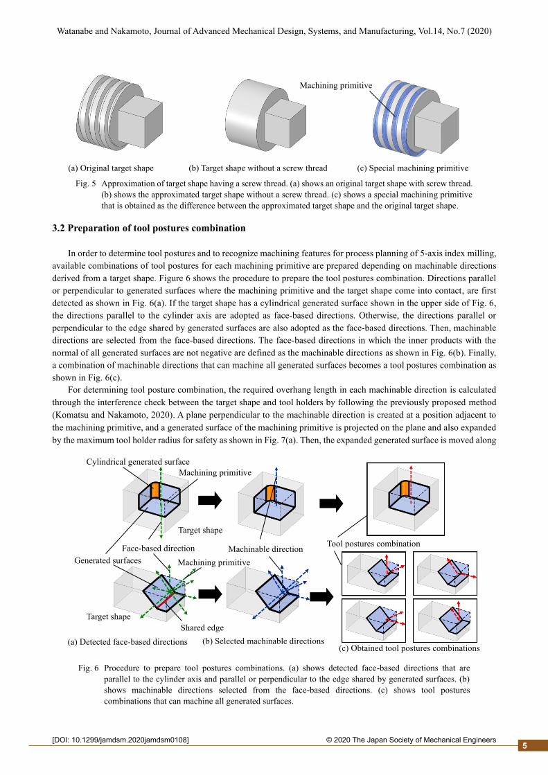
In order to determine tool postures and to recognize machining features for process planning of 5-axis index milling,
available combinations of tool postures for each machining primitive are prepared depending on machinable directions
derived from a target shape. Figure 6 shows the procedure to prepare the tool postures combination. Directions parallel
or perpendicular to generated surfaces where the machining primitive and the target shape come into contact, are first
detected as shown in Fig. 6(a). If the target shape has a cylindrical generated surface shown in the upper side of Fig. 6,
the directions parallel to the cylinder axis are adopted as face-based directions. Otherwise, the directions parallel or
perpendicular to the edge shared by generated surfaces are also adopted as the face-based directions. Then, machinable
directions are selected from the face-based directions. The face-based directions in which the inner products with the
normal of all generated surfaces are not negative are defined as the machinable directions as shown in Fig. 6(b). Finally,
a combination of machinable directions that can machine all generated surfaces becomes a tool postures combination as
shown in Fig. 6(c).
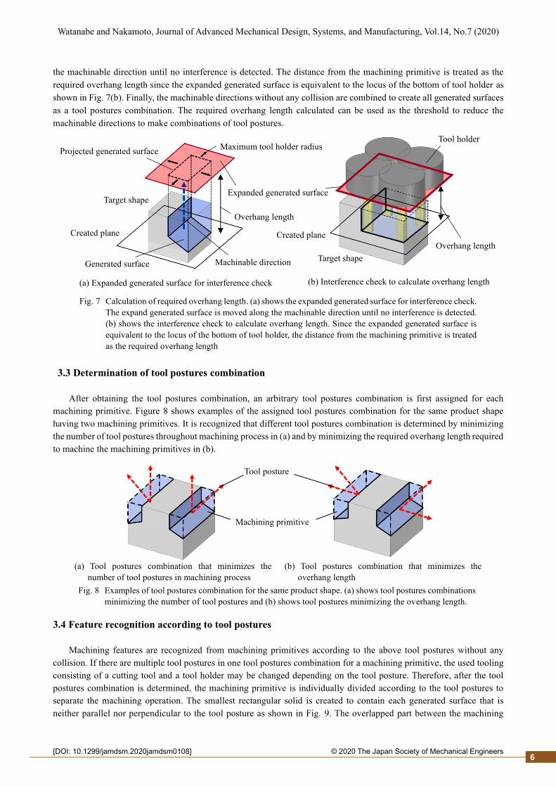
For determining tool posture combination, the required overhang length in each machinable direction is calculated
through the interference check between the target shape and tool holders by following the previously proposed method
(Komatsu and Nakamoto, 2020). A plane perpendicular to the machinable direction is created at a position adjacent to
the machining primitive, and a generated surface of the machining primitive is projected on the plane and also expanded
by the maximum tool holder radius for safety as shown in Fig. 7(a). Then, the expanded generated surface is moved along
Fig. 6 Procedure to prepare tool postures combinations. (a) shows detected face-based directions that are
parallel to the cylinder axis and parallel or perpendicular to the edge shared by generated surfaces. (b)
shows machinable directions selected from the face-based directions. (c) shows tool postures
combinations that can machine all generated surfaces.
(a) Original target shape (b) Target shape without a screw thread (c) Special machining primitive
Machining primitive
Tool postures combination Face-based direction
Cylindrical generated surface
Machinable direction
(a) Detected face-based directions
Generated surfaces
(b) Selected machinable directions (c) Obtained tool postures combinations
Shared edge
Machining primitive
Machining primitive
Target shape
Target shape
Fig. 5 Approximation of target shape having a screw thread. (a) shows an original target shape with screw thread.
(b) shows the approximated target shape without a screw thread. (c) shows a special machining primitive
that is obtained as the difference between the approximated target shape and the original target shape.
5
2© 2020 The Japan Society of Mechanical Engineers[DOI: 10.1299/jamdsm.2020jamdsm0108]
Watanabe and Nakamoto, Journal of Advanced Mechanical Design, Systems, and Manufacturing, Vol.14, No.7 (2020)
the machinable direction until no interference is detected. The distance from the machining primitive is treated as the
required overhang length since the expanded generated surface is equivalent to the locus of the bottom of tool holder as
shown in Fig. 7(b). Finally, the machinable directions without any collision are combined to create all generated surfaces
as a tool postures combination. The required overhang length calculated can be used as the threshold to reduce the
machinable directions to make combinations of tool postures.
3.3 Determination of tool postures combination
After obtaining the tool postures combination, an arbitrary tool postures combination is first assigned for each
machining primitive. Figure 8 shows examples of the assigned tool postures combination for the same product shape
having two machining primitives. It is recognized that different tool postures combination is determined by minimizing
the number of tool postures throughout machining process in (a) and by minimizing the required overhang length required
to machine the machining primitives in (b).
3.4 Feature recognition according to tool postures
Machining features are recognized from machining primitives according to the above tool postures without any
collision. If there are multiple tool postures in one tool postures combination for a machining primitive, the used tooling
consisting of a cutting tool and a tool holder may be changed depending on the tool posture. Therefore, after the tool
postures combination is determined, the machining primitive is individually divided according to the tool postures to
separate the machining operation. The smallest rectangular solid is created to contain each generated surface that is
neither parallel nor perpendicular to the tool posture as shown in Fig. 9. The overlapped part between the machining
Tool posture
Machining primitive
(a) Tool postures combination that minimizes the
number of tool postures in machining process
(b) Tool postures combination that minimizes the
overhang length
Fig. 8 Examples of tool postures combination for the same product shape. (a) shows tool postures combinations
minimizing the number of tool postures and (b) shows tool postures minimizing the overhang length.
Fig. 7 Calculation of required overhang length. (a) shows the expanded generated surface for interference check.
The expand generated surface is moved along the machinable direction until no interference is detected.
(b) shows the interference check to calculate overhang length. Since the expanded generated surface is
equivalent to the locus of the bottom of tool holder, the distance from the machining primitive is treated
as the required overhang length
(a) Expanded generated surface for interference check (b) Interference check to calculate overhang length
Machinable direction
Expanded generated surface
Created plane Created plane
Projected generated surface Maximum tool holder radius
Generated surface
Target shape
Target shape
Tool holder
Overhang length
Overhang length
6

2© 2020 The Japan Society of Mechanical Engineers[DOI: 10.1299/jamdsm.2020jamdsm0108]
Watanabe and Nakamoto, Journal of Advanced Mechanical Design, Systems, and Manufacturing, Vol.14, No.7 (2020)
primitive and the created rectangular solid is defined as the volume that cannot be machined with the tool posture in this
study. Then, the overlapped part is removed from the original machining primitive, and the remained part becomes a
machining primitive machined with the tool posture. The removed part becomes a new machining primitive machined
with another tool posture. By repeating this procedure for whole tool postures, the original machining primitive is divided
repeatedly in order to remove unmachined volume. Finally, after machining sequence is allocated to the machining
primitives based on specific conditions such as machining volume order, machining features are recognized following
the previous study.
4. Case study
A case study is conducted to confirm that the proposed method of machining features recognition is useful to
effectively deal with process planning of 5-axis index milling on multi-tasking machine tools.
The assumed multi-tasking machine tool has a milling function with 5-axis control, two confronting spindles and a
lower turret with plural cutting tools. In terms of the tool holders, the assumed maximum radius is 50 mm. As the cutting
tools, a single point turning tool for turning, two types of square end mills (6 and 12 mm in diameter), and a drill (8 mm
in diameter) are supposed, and it is assumed that all machining primitives are machined by these cutting tools. Moreover,
cylindrical primitives that the center axes match with the turning spindle are machined by turning, and other machining
primitives are machined by milling or drilling. Both workpiece and target shapes are prepared as the input CAD models
as shown in Fig. 10, they are created so that Z axis of the CAD coordinates system agrees with the center axis of turning
spindle. In addition, tool postures for machining primitives are determined by using direction vectors in the CAD
coordinate system. Because the workpiece rotates in turning, the tool postures for turning are assumed to be parallel to
the X axis direction.
In this case study, three process patterns (A, B and C) are supposed by using the multi-tasking machine tool. In
Pattern A, machining features are recognized by the previous method for turning and 3-axis control milling on multi-
tasking machine tools. In Pattern B, machining features are recognized by using the proposed method in this study for
turning and 5-axis index milling. In Pattern C, cylindrical machining primitives for turning are additionally obtained even
when the target shape does not have a cylinder part for the same machining features recognition in Pattern B. In Pattern
A, each tool posture is fixed as the normal vector of the generated surface of machining primitive. In Patterns B and C,
the tool postures combinations are determined to minimize the required overhang length for machining primitives that
are machined by 5-axis index milling. In any pattern, turning has the priority for early machining sequence compared to
any method of milling, and the machining primitive that is farther from the center axis of turning spindle has the priority
in turning. In 5-axis index milling, the tool posture that can machine larger volume has the priority, and the machining
primitive that is farther from the center axis of turning spindle has the priority for early machining sequence in the same
tool posture.
Table 1 summarizes the recognized 12 machining features in Pattern A. In the machining sequence 1, turning is
selected as the machining method for cylindrical machining feature Face C + Boss C defined in the previous study, and
Fig. 9 Division of machining primitive according to tool posture. A machining primitive is divided by removing
unmachined volume in each tool posture. A cuboid is created to detect unmachined volume, and the
overlapped part between the machining primitive and the created rectangular solid is defined as
unmachined volume with the tool posture.
Tool posture
Machining primitive
Removed part
Created rectangular solid Remained part
7

2© 2020 The Japan Society of Mechanical Engineers[DOI: 10.1299/jamdsm.2020jamdsm0108]
Watanabe and Nakamoto, Journal of Advanced Mechanical Design, Systems, and Manufacturing, Vol.14, No.7 (2020)
3-axis control milling is selected as the machining method for other machining features. In the sequences 11 and 12, tool
postures (1,0,1) and (-1,0,1) are conveniently determined for 3-axis control milling because the tool posture is fixed as
the normal vector of the generated surface. However, these tool postures are impossible in 3-axis control milling and
their machining primitives are not machined completely by 3-axis control milling. Therefore, the previous method can
not deal with machining primitives that are required to be machined by using inclined tool postures.
Turning 3-axis control milling
Seq. 1: Face C + Boss C Seq. 2: Step Seq. 3: Step Seq. 4: Step Seq. 5: Step
Dv : (1, 0, 0) Dv : (0, 1, 0) Dv : (1, 0, 0)
3-axis control milling
Seq. 6: Step Seq. 7: Step Seq. 8: Step Seq. 9: Step Seq. 10: Through hole
Dv : (1, 0, 0) Dv : (-1, 0, 0) Dv : (0, -1, 0)
3-axis control milling
Seq. 11: Face P Seq. 12: Face P
Dv : (1, 0, 1) Dv : (-1, 0, 1)
(a) Workpiece shape (b) Target shape
Center axis of turning spindle
120 mm
80 mm 120 mm
80 mm
Fig. 10 Workpiece and target shapes for case study.
Table 1 Result of recognition of machining features in Pattern A. There are 1 feature machined by turning
and 11 features machined by 3-axis control milling. Each tool posture is fixed as the normal vector
of the generated surface of machining primitive.
Tool posture
Dv: Direction vector of tool posture
Unmachinable primitive Unmachinable primitive
8

2© 2020 The Japan Society of Mechanical Engineers[DOI: 10.1299/jamdsm.2020jamdsm0108]
Watanabe and Nakamoto, Journal of Advanced Mechanical Design, Systems, and Manufacturing, Vol.14, No.7 (2020)
Table 2 summarizes the recognized 15 machining features in Pattern B. In the machining sequence 1, turning is
similarly selected as the machining method for machining features. On the other hand, 5-axis index milling is selected as
the machining method for other machining features. Comparing the machining features recognized in Pattern A, it is
found that machining feature Step of sequence 6 with the fixed tool posture in Pattern A is recognized as two machining
features Step and Face of sequences 6 and 12 with the suitable tool postures in Pattern B as shown in Fig. 11. Therefore,
it is understood that machining features can be recognized for 5-axis index milling by the proposed method to determine
tool postures and to divide machining primitive for removing the unmachined volume.
Turning 5-axis index milling
Seq. 1: Face C + Boss C Seq. 2: Step Seq. 3: Step Seq. 4: Step Seq. 5: Step
Dv : (1, 0, 0) Dv : (0, 1, 0) Dv : (1, 0, 0)
5-axis index milling
Seq. 6: Step Seq. 7: Step Seq. 8: Step Seq. 9: Step Seq. 10: Through hole
Dv : (1, 0, 0) Dv : (-1, 0, 0) Dv : (0, -1, 0)
5-axis index milling
Seq. 11: Face P Seq. 12: Face P Seq. 13: Face P Seq. 14: Face P Seq. 15: Face P
Dv : (1, 0, 1) Dv : (-1, 0, 1) Dv : (0, 1, 2)
Table 2 Result of recognition of machining features in Pattern B. There are 1 feature machined by turning
and 14 features machined by 5-axis index milling. The tool postures for each machining primitive
are determined with respect to the required overhang length, and machining features are recognized
to remove the unmachined volume.
Tool posture
Machining feature in Pattern A Machining features in Pattern B
Seq. 6 : Step
Seq. 6 : Step
Seq. 12 : Face
P
Tool posture Unmachined volume
Fig. 11 Comparison of machining features recognition in Patterns A and B. In Pattern B, machining primitive
is divided according to tool postures to remove unmachinable volume, and two machining features are
recognized from the original machining primitive.
Dv: Direction vector of tool posture
9

2© 2020 The Japan Society of Mechanical Engineers[DOI: 10.1299/jamdsm.2020jamdsm0108]
Watanabe and Nakamoto, Journal of Advanced Mechanical Design, Systems, and Manufacturing, Vol.14, No.7 (2020)
Table 3 summarizes the recognized 18 machining features in Pattern C. In the machining sequences 1 to 4, turning
is selected as the machining method for machining features, and 5-axis index milling is selected as the machining method
for other machining features. Figure 12 shows that the created simplified target shape and the obtained additional
cylindrical machining primitive in Pattern C. It is found that the machining features machined by turning can be
recognized regardless of the target shape by creating a simplified target shape having a cylinder part for turning.
The results of case study confirm that machining primitives are divided according to the tool postures combination
to remove unmachined volume and machining features are successfully recognized for 5-axis index milling by the
proposed machining features recognition method. Moreover, cylindrical machining primitives for turning are additionally
obtained even when the target shape does not have a cylinder part to increase the flexibility of machining operations on
multi-tasking machine tools. As a result, it is found that process planning of 5-axis index milling would be realized based
on the machining features recognition method.
Turning 5-axis index milling
Seq. 1: Face C + Boss C Seq. 2: Face C + Boss C Seq. 3: Face C + Boss C Seq. 4: Face C + Boss C Seq. 5: Step
Dv : (1, 0, 0) Dv : (0, 1, 0)
5-axis index milling
Seq. 6: Step Seq. 7: Step Seq. 8: Step Seq. 9: Step Seq. 10: Step
Dv : (0, 1, 0) Dv : (1, 0, 0) Dv : (-1, 0, 0)
5-axis index milling
Seq. 11: Step Seq. 12: Step Seq. 13:Through hole Seq. 14: Face P Seq. 15: Face P
Dv : (-1, 0, 0) Dv : (0, -1, 0) Dv : (1, 0, 1)
5-axis index milling
Seq. 16: Face P Seq. 17: Face P Seq. 18: Face P
Dv : (-1, 0, 1) Dv : (0, 1, 2)
Table 3 Result of recognition of machining features in Pattern C. There are 4 features machined by turning
and 14 features machined by 5-axis index milling. Cylindrical machining primitives for turning are
obtained even when the target shape does not have a cylinder part.
Tool posture
Dv: Direction vector of tool posture
10

2© 2020 The Japan Society of Mechanical Engineers[DOI: 10.1299/jamdsm.2020jamdsm0108]
Watanabe and Nakamoto, Journal of Advanced Mechanical Design, Systems, and Manufacturing, Vol.14, No.7 (2020)
As Pattern D, another case study is conducted to confirm that the proposed method can also applied to process
planning of 5-axis index milling on 5-axis controlled machining centers. The assumed 5-axis controlled machining center
has two rotational axes B and C. The supposed maximum tool holder radius and the cutting tools are the same as the case
study mentioned above, and all machining primitives are machined by 5-axis index milling using milling tools. The target
shape and workpiece shape are also the same, and it is assumed that Z axis of the CAD coordinates system agrees with
Z axis of the machine coordinate system. The tool postures combinations are determined to minimize the required
5-axis index milling
Seq. 1: Step Seq. 2: Step Seq. 3: Step Seq. 4: Step Seq. 5: Step
Dv : (0, 1, 0) Dv : (1, 0, 0)
5-axis index milling
Seq. 6: Step Seq. 7: Step Seq. 8: Step Seq. 9: Through hole Seq. 10: Face C + Boss C
Dv : (-1, 0, 0) Dv : (-1, 0, 0) Dv : (0, 0, 1)
5-axis index milling
Seq. 11: Face P Seq. 12: Face P Seq. 13: Face P Seq. 14: Face P Seq. 15: Face P
Dv : (1, 0, 1) Dv : (-1, 0, 1) Dv : (0, 1, 2)
Fig. 12 Simplified target shape and additional machining primitive in Pattern C. It is found that the created
simplified target shape contains the original target shape and additional machining primitives for
turning are obtained regardless of the original target shape.
Table 4 Result of recognition of machining features in Pattern D. All features are machined by 5-axis index
milling on a 5-axis controlled machining center.
Tool posture
Dv: Direction vector of tool posture
Workpiece shape Simplified target shape
Original target shape
Additional machining primitive
11

2© 2020 The Japan Society of Mechanical Engineers[DOI: 10.1299/jamdsm.2020jamdsm0108]
Watanabe and Nakamoto, Journal of Advanced Mechanical Design, Systems, and Manufacturing, Vol.14, No.7 (2020)
overhang length for machining primitives. The tool posture that can machine larger volume has the priority for early
machining sequence, and the machining primitive that is farther from the center axis of turning spindle has the priority
for early machining sequence in the same tool posture. Table 4 summarizes the recognized 18 machining features in this
case study. It is found that machining features are recognized for 5-axis index milling and the proposed method can be
easily applied to process planning of 5-axis index milling on 5-axis controlled machining centers.
Machining time in each case study is estimated by using a commercial CAM system (ESPRIT 2015, DP Technology
Corp.). The workpiece material is assumed to be carbon steel, and cutting conditions are determined based on a tool
catalog according to the previous study (Inoue and Nakamoto, 2020). A single point turning tool is selected to machining
features of the cylinder type for turning. The drill is applied to machining features of the cylinder type when the tool
diameter is the same as the diameter of the machining feature. Square end mills are adopted for the other machining
features, and the largest tool is used within the smallest distance between confronting generated surfaces. Table 5
summarizes the estimated machining time, not including the time for tool changes. In Pattern A, two unmachinable
primitives are remained because the available tool posture is limeted in 3-axis control milling. Though the machining
time becomes longer in Pattern B, whole machining primitives are completely machined by 5-axis index milling. In
Pattern C, the machining time is the shortest by obtaining additional machining primitives for turning that the cutting
speed is relatively high. On the other hand, the machining time is the longest in Pattern D becasue the target shape is
machined only by 5-axis index milling on the 5-axis controlled machining center. From the result, it is found that 5-axis
index milling on multi-tasking machine tools realized by the proposed machining features recognition method results in
reducing the machining time successfully.
Multi-tasking machine tools 5-axis controlled
machining center
Pattern A
by turning and 3-axis
control milling *1
Pattern B
by turning and 5-axis
index milling
Pattern C
by turning and 5-axis
index milling *2
Pattern D
by 5-axis index milling
Time [min] 233.3 266.4 181.1 456.8
*1 Unmachinable primitives are remained.
*2 Machining primitives for turning are additionally obtained.
5. Conclusions
This study aims to propose a novel machining features recognition method can be applied to process planning of 5-
axis index milling that is an effective machining method for complex shapes on multi-tasking machine tools. In the
proposed method, machining primitives are obtained by dividing the removal volume, and the combinations of tool
postures are prepared for each machining primitive depending on the directions in which the machining primitive can be
machined. Moreover, cylindrical machining primitives for turning are obtained regardless of the target shape in order to
increase the flexibility of machining process on multi-tasking machine tools. The tool postures during 5-axis index
milling are determined by referring specific information such as the number of tool postures. The machining primitives
are divided again in each determined tool posture to recognize machining features in order to remove unmachined
volume. From the conducted case study, it is confirmed that machining features are successfully recognized by the
proposed method for 5-axis index milling on multi-tasking machine tools. Moreover, the proposed method is verified to
be applied to process planning of 5-axis index milling on 5-axis controlled machining centers.
Table 5 Machining time estimated by a commercial CAM system for the four patterns. In Pattern A,
unmachinable primitives are remained. Though the machining time becomes longer in Pattern
B, whole machining primitives are completely machined by 5-axis index milling. Machining
time becomes the shortest by obtaining additional machining primitives for turning in Pattern
C. In Pattern D, all machining primitives are machined only by 5-axis control milling.
12

2© 2020 The Japan Society of Mechanical Engineers[DOI: 10.1299/jamdsm.2020jamdsm0108]
Watanabe and Nakamoto, Journal of Advanced Mechanical Design, Systems, and Manufacturing, Vol.14, No.7 (2020)
Acknowledgements
This study was financially supported by Project Research RU-07 of the Machine Tool Engineering Foundation, and
the authors would like to express sincere gratitude to AIKOKU ALPHA Corp. for their kind support throughout this
study.
References
Dwijayanti, K. and Aoyama, H., Basic study on process planning for turning-milling center based on machining feature
recognition, Journal of Advanced Mechanical Design, Systems and Manufacturing, Vol. 8, No. 4, (2014), DOI:
10.1299/jamdsm.2014jamdsm0058.
Fu, W., Eftekharian, A. A. and Campbell, M. I., Automated manufacturing planning approach based on volume
decomposition and graph-grammars, Journal of Computing and Information Science in Engineering, Vol. 13, No. 2,
(2013), 021010.
Inoue, Y. and Nakamoto, K., Development of a CAPP system for multi-tasking machine tools to deal with complicated
machining operations, Journal of Advanced Mechanical Design, Systems, and Manufacturing, Vol. 14, No. 1,
(2020), DOI: 10.1299/jamdsm.2020jamdsm0006.
Zhu, J., Kato, M., Tanaka, T., Yoshioka, H. and Saito, Y., Graph based automatic process planning system for multi-
tasking machine, Journal of Advanced Mechanical Design, Systems, and Manufacturing, Vol. 9, No. 3, (2015), DOI:
10.1299/jamdsm.2015jamdsm0034.
Kaneko, J., Yamauchi, Y. and Horio, K., Fast estimation method of machinable area of workpiece surface for 3+2-axis
control machining using graphics device – visualization algorithm of machinable area and minimum shank length
with texture projection technique –, International Journal of Automation Technology, Vol. 8, No. 3, (2014), pp. 420-
427.
Komatsu, W., Inoue, K. and Nakamoto, K., Proposal of computer aided process planning of parts machining using
workholding devices, Journal of Advanced Mechanical Design, Systems, and Manufacturing, Vol. 14, No. 3, (2020),
DOI: 10.1299/jamdsm.2020jamdsm0033.
Li, Y., Ding, Y., Mou, W. and Guo, H., Feature recognition technology for aircraft structural parts based on a holistic
attribute adjacency graph, Proceedings of the Institution of Mechanical Engineers, Part B: Journal of Engineering
Manufacture, Vol. 224, Issue. 2, (2010), pp. 271-278.
Huang, W. and Inui, M., Algorithm for determining the optimal cutter and shank length for fixed 5-axis machining,
Journal of the Japan Society of Mechanical Engineers, Vol. 76, No. 2, (2010), pp. 220-225 (in Japanese).
Nishida, I. and Shirase, K., Automatic determination of cutting conditions for NC program generation by reusing
machining case data based on geometric properties of removal volume, Journal of Advanced Mechanical Design,
Systems, and Manufacturing, Vol. 12, No. 4, (2018), DOI: 10.1299/jamdsm.2018jamdsm0093.
Rahmani, K. and Arezoo, B., A hybrid hint-based and graph-based framework for recognition of interacting milling
features, Compters in Industry, Vol. 58, Issue. 4, (2007), pp. 304-312.
Shi, Y., Yicha, Z., Xia, K. and Harik, R., A Critical review of feature recognition techniques, Computer-Aided Design
and Applications, Vol. 17, No. 5, (2020), pp. 861-899.
Sunil, B. V. and Pande, S, Automatic recognition of machining features using artificial neural networks, International
Journal of Advanced Manufacturing Technology, Vol. 41, No. 9, (2009), pp. 931-947.
Ueno, A. and Nakamoto, K., Proposal of machining features for CAPP system for multi-tasking machine tools,
Transaction of the JSME, Vol. 81, No. 825 (2015), DOI: 10.1299/transjsme.15–00108 (in Japanese).
Yamada, M., Kondo, T., Tanaka, F. and Kishinami, T., Tilted tool axis machining on 5-axis machine tools, International
Journal of Automation Technology, Vol. 1, No. 2, (2007), pp. 120-127.
Yamada, M., Kondo, T. and Wakasa, K., High efficiency machining for integral shaping from simplicity materials using
five-axis machine tools, International Journal of Automation Technology, Vol. 10, No. 5, (2016), pp. 804-812.
13