Proposal for editorial corrections to … for editorial corrections to ECE/TRANS/WP.29/GRPE/2018/4...
30
Submitted by the IWG on WLTP Informal document GRPE-76-05 76 th GRPE, 9-12 January 2018 Agenda item 3(b) Proposal for editorial corrections to ECE/TRANS/WP.29/GRPE/2018/4 Submitted by the Informal Working Group on Worldwide harmonized Light vehicles Test Procedure (WLTP) * The text reproduced below was prepared by the Evaporative Task Force of the Informal Working Group (IWG) on Worldwide harmonized Light vehicles Test Procedure (WLTP) in line with Phase 2 of its mandate (ECE/TRANS/WP.29/AC.3/44). The IWG on WLTP referred to a first draft of this proposal (GRPE-75-16) at the seventy-fifth session of the Working Party on Pollution and Energy (GRPE) (see report ECE/TRANS/WP.29/GRPE/75, para. 12). The text is reproduced as a consolidated version. The modifications to ECE/TRANS/WP.29/GRPE/2018/4 are marked in "tracked changes" Amendment 1 to global technical regulation No. 19 on Evaporative emission test procedure for the Worldwide harmonized Light vehicles Test Procedure (WLTP EVAP) I. Statement of technical rationale and justification A. Introduction 1. The compliance with emission standards is a central issue of vehicle certification worldwide. Emissions comprise criteria pollutants having a direct (mainly local) negative impact on health and environment, as well as pollutants having a negative environmental impact on a global scale. Regulatory emission standards typically are complex documents, describing measurement procedures under a variety of well-defined conditions, setting limit values for emissions, but also defining other elements such as the durability and on-board monitoring of emission control devices. 2. Most manufacturers produce vehicles for a global clientele or at least for several regions. Albeit vehicles are not identical worldwide since vehicle types and models tend to cater to local tastes and living conditions, the compliance with different emission standards in each region creates high burdens from an administrative and vehicle design point of view. Vehicle manufacturers, therefore, have a strong interest in harmonizing vehicle emission test procedures and performance requirements as much as possible on a global scale. Regulators also have an interest in global harmonization since it offers more efficient * In accordance with the programme of work of the Inland Transport Committee for 2014–2018 (ECE/TRANS/240, para. 105 and ECE/TRANS/2014/26, programme activity 02.4), the World Forum will develop, harmonize and update Regulations in order to enhance the performance of vehicles. The present document is submitted in conformity with that mandate.
Transcript of Proposal for editorial corrections to … for editorial corrections to ECE/TRANS/WP.29/GRPE/2018/4...

Submitted by the IWG on WLTP Informal document GRPE-76-05 76th GRPE, 9-12 January 2018
Agenda item 3(b)
Proposal for editorial corrections to ECE/TRANS/WP.29/GRPE/2018/4
Submitted by the Informal Working Group on Worldwide harmonized Light vehicles Test Procedure (WLTP)*
The text reproduced below was prepared by the Evaporative Task Force of the Informal Working Group (IWG) on Worldwide harmonized Light vehicles Test Procedure (WLTP) in line with Phase 2 of its mandate (ECE/TRANS/WP.29/AC.3/44). The IWG on WLTP referred to a first draft of this proposal (GRPE-75-16) at the seventy-fifth session of the Working Party on Pollution and Energy (GRPE) (see report ECE/TRANS/WP.29/GRPE/75, para. 12). The text is reproduced as a consolidated version. The modifications to ECE/TRANS/WP.29/GRPE/2018/4 are marked in "tracked changes"
Amendment 1 to global technical regulation No. 19 on Evaporative emission test procedure for the Worldwide harmonized Light vehicles Test Procedure (WLTP EVAP)
I. Statement of technical rationale and justification
A. Introduction
1. The compliance with emission standards is a central issue of vehicle certification worldwide. Emissions comprise criteria pollutants having a direct (mainly local) negative impact on health and environment, as well as pollutants having a negative environmental impact on a global scale. Regulatory emission standards typically are complex documents, describing measurement procedures under a variety of well-defined conditions, setting limit values for emissions, but also defining other elements such as the durability and on-board monitoring of emission control devices.
2. Most manufacturers produce vehicles for a global clientele or at least for several regions. Albeit vehicles are not identical worldwide since vehicle types and models tend to cater to local tastes and living conditions, the compliance with different emission standards in each region creates high burdens from an administrative and vehicle design point of view. Vehicle manufacturers, therefore, have a strong interest in harmonizing vehicle emission test procedures and performance requirements as much as possible on a global scale. Regulators also have an interest in global harmonization since it offers more efficient
* In accordance with the programme of work of the Inland Transport Committee for 2014–2018
(ECE/TRANS/240, para. 105 and ECE/TRANS/2014/26, programme activity 02.4), the World Forum will develop, harmonize and update Regulations in order to enhance the performance of vehicles. The present document is submitted in conformity with that mandate.

ECE/TRANS/WP.29/GRPE/2018/4 as amended
2
development and adaptation to technical progress, potential collaboration at market surveillance and facilitates the exchange of information between authorities.
3. As a consequence stakeholders launched the work on the Worldwide harmonized Light vehicle Test Procedure (WLTP) which aims at harmonizing emission-related test procedures for light duty vehicles to the extent this is possible. One of the aspects covered within the mandate for WLTP is the evaporative emission test procedure.
4. Evaporative emissions from vehicles is a complex phenomenon which depends on multiple factors, that range from climate conditions to fuel properties, from driving and parking patterns to the technology used to control these emissions.
5. Evaporative emissions from a vehicle can be defined, in a very generic way, as Volatile Organic Compounds (VOCs) emitted by the vehicle itself in different operating conditions but not directly derived from the combustion process. In petrol vehicles the most important potential source of evaporative emissions is the loss of fuel through the evaporation and permeation mechanisms from the fuel storing system. Fuel-related evaporative emissions may occur during any vehicle operation including parking events, normal driving and vehicle refuelling.
6. VOCs may also be emitted by specific components of the vehicle such as tyres, interior trim, plastics or by other fluids (e.g. windshield washer fluid). These non-fuel related emissions are usually quite low, not dependent on how the vehicle is used or on the quality of the fuel, and tend to decrease over time. Evaporative emissions in general do not represent a significant problem for diesel vehicles due to the very low vapour pressure of diesel fuel.
7. During parking events, an increase of the temperature of the fuel temperature in the fuel tank system increases due to rising ambient temperature and solar radiation may lead to evaporation of the lightest petrol fractions with a corresponding increase of the pressure inside the tank. As a result of the increased temperature and consequent evaporation of the fuel, as well as expansion of the air/fuel vapour mixture, the pressure inside the fuel tank system increases significantly. This may lead the evaporation of the lightest petrol fractions with a corresponding increase of the pressure inside the fuel tank system. The In non-sealed fuel tank systems, which are mostly used in conventional vehicles, the increase of the pressure inside the system is limited by the high probability of purging vapours inside the fuel tank systemdesign, and the pressure is usually vented mainly to the canister(s)atmosphere through a pressure relief valve, so that the tank pressure is maintained slightly above atmospheric pressure. If the pressure inside the tank rises above that value, a mixture of air and petrol vapours may be released into the atmosphere. In modern vehicles the tank is vented through an activatedThe carbon canister which adsorbs and stores the hydrocarbons (HC) preventing emissions to the atmosphere. However, Tthis carbon canister has a limited adsorbing capacity (depending on several factors of which the most important are the mass and carbon quality, mass, and fuel specification of the carbon as well as the ambient temperature) and has mustto be periodically purged to desorb the stored hydrocarbons. This occurs during vehicle driving events when the combustion engine is running since part of the combustion air flows through the canister removing the adsorbed hydrocarbons which are then burned inside the engine.
Due to the potentially limited operation time of the combustion engine in hybrid electric vehicles, theThe use of sealed fuel tank systems may representis one of an the alternative solutions to the system described above especially for hybrid electric vehiclesto control evaporative emissions. Due to the potentially reduced time of operation of the combustion engine in hybrid electric vehicles, proper purging of the carbon canister may represent an issue. As a consequence the carbon canister may not have enough
ECE/TRANS/WP.29/GRPE/2018/4 as amended
3
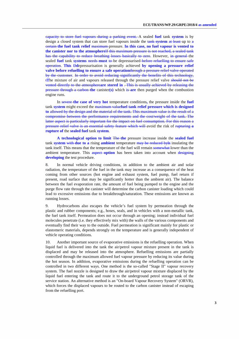
capacity to store fuel vapours during a parking event. A sealed fuel tank system is by design a closed system that can store fuel vapours inside the tank system at least up to a certain the fuel tank relief maximum pressure. In this case, no fuel vapour is vented to the canister nor to the atmosphereIf this maximum pressure is not reached, a sealed tank has the capability to reduce breathing losses basically to zero. However, in general the sealed fuel tank systems needs must to be depressurised before refuelling to ensure safe operation. This Ddepressurisation is generally achieved by opening a pressure relief valve before refuelling to ensure a safe operationthrough a pressure relief valve operated by the customer. In order to avoid reducing significantly the benefits of this technology, tThe mixture of air and vapours released through the pressure relief valve should not be vented directly to the atmosphereare stored in . This is usually achieved by releasing the pressure through a carbon the canister(s) which is are then purged when the combustion engine runs.
In severe the case of very hot temperature conditions, the pressure inside the fuel tank system might exceed the maximum valuefuel tank relief pressure which is designed to allowed by the design and the material of the tank. This maximum value is the result of a compromise between the performance requirements and the cost/weight of the tank. The latter aspect is particularly important for the impact on fuel consumption. For this reason a pressure relief valve is an essential safety feature which will avoid the risk of rupturing a rupture of the sealed fuel tank system.
A technological option to limit The the pressure increase inside the sealed fuel tank system with due to a rising ambient temperature may be reduced byis insulating the tank itself. This means that the temperature of the fuel will remain somewhat lower than the ambient temperature. This aspect option has been taken into account when designing developing the test procedure.
8. In normal vehicle driving conditions, in addition to the ambient air and solar radiation, the temperature of the fuel in the tank may increase as a consequence of the heat coming from other sources (hot engine and exhaust system, fuel pump, fuel return if present, road surface that may be significantly hotter than the ambient air). The balance between the fuel evaporation rate, the amount of fuel being pumped to the engine and the purge flow rate through the canister will determine the carbon canister loading which could lead to excessive emissions due to breakthrough/saturation. These emissions are known as running losses.
9. Hydrocarbons also escapes the vehicle’s fuel system by permeation through the plastic and rubber components; e.g., hoses, seals, and in vehicles with a non-metallic tank, the fuel tank itself. Permeation does not occur through an opening; instead individual fuel molecules penetrate (i.e. they effectively mix with) the walls of the various components and eventually find their way to the outside. Fuel permeation is significant mainly for plastic or elastomeric materials, depends strongly on the temperature and is generally independent of vehicle operating conditions.
10. Another important source of evaporative emissions is the refuelling operation. When liquid fuel is delivered into the tank the air/petrol vapour mixture present in the tank is displaced and may be released into the atmosphere. Refuelling emissions are partially controlled through the maximum allowed fuel vapour pressure by reducing its value during the hot season. In addition, evaporative emissions during the refuelling operation can be controlled in two different ways. One method is the so-called "Stage II" vapour recovery system. The fuel nozzle is designed to draw the air/petrol vapour mixture displaced by the liquid fuel entering the tank and route it to the underground petrol storage tank of the service station. An alternative method is an "On-board Vapour Recovery System" (ORVR), which forces the displaced vapours to be routed to the carbon canister instead of escaping from the refuelling port.

ECE/TRANS/WP.29/GRPE/2018/4 as amended
4
11. An unintended source of HC emissions may occur from leaks in the system. Leaks may occur in the vapour and/or the liquid system as a result of deterioration and/or faulty operations. Examples of deterioration are corrosion of metallic components (e.g. fuel lines, tanks), cracking of rubber hoses, hardening of seals, mechanical failures. On-board diagnostic systems have been developed to check the integrity of the fuel system and are required in some regions.
12. In the existing regional type approval procedures, the various situations that can lead to significant evaporative emissions have been addressed either by developing different tests or by adopting different measures. As an example, in certain regions refuelling emissions are controlled by mandating the use of the Stage II vapour recovery system while in other regions the ORVR approach has been chosen.
13. The need to represent real driving conditions as much as possible to make the performance of vehicles at certification and in real life comparable puts therefore some limitations on the level of harmonization to be achieved since, for instance, ambient temperatures vary widely on a global scale while other potential sources of evaporative emissions are addressed in different ways across the regions (e.g. refuelling emissions or potential leaks).
14. At this time, the WLTP EVAP test procedure focuses only on the evaporative emissions that can occur during parking events. Running losses and refuelling emissions are out of the scope of the current WLTP EVAP procedure. However the venting of vapour from a sealed tank immediately prior to refuelling (also known as depressurisation puff loss emissions) is within the scope of this procedure.
15. The purpose of a UN global technical regulation (UN GTR) is its implementation into regional legislation by as many Contracting Parties as possible. However, the scope of regional legislations in terms of vehicle categories concerned depends on regional conditions and cannot be predicted for the time being. On the other hand, according to the rules of the 1998 Agreement, Contracting Parties implementing a UN GTR must include all equipment falling into the formal UN GTR scope. Care must be taken so that an unduly large formal scope of the UN GTR does not prevent its regional implementation. Therefore the formal scope of this UN GTR is kept mainly for light duty vehicles. However, this limitation of the formal UN GTR scope does not indicate that it could not be applied to a larger group of vehicle categories by regional legislation. In fact, Contracting Parties are encouraged to extend the scope of regional implementations of this UN GTR if this is technically, economically and administratively appropriate.
B. Procedural background and future development of the WLTP EVAP
16. In its November 2007 session, the World Forum for Harmonization of Vehicle Regulations (WP.29) decided to set up an Informal Working Group (IWG) under the Working Party on Pollution and Energy (GRPE) to prepare a road map for the development of WLTP. After various meetings and intense discussions, WLTP presented in June 2009 a first road map consisting of three phases, which was subsequently revised a number of times and contains the following main tasks:
(a) Phase 1 (2009–2014): Development of the worldwide harmonized light duty driving cycle and associated test procedure for the common measurement of criteria compounds, CO2, fuel and energy consumption;
(b) Phase 2 (2014–2018): Low temperature/high altitude test procedure, durability, in-service conformity, technical requirements for On-Board Diagnostics (OBD), Mobile Air-Conditioning (MAC) system energy efficiency, off-cycle/real driving emissions, and evaporative emission;
ECE/TRANS/WP.29/GRPE/2018/4 as amended
5
(c) Phase 3 (2018-…): Emission limit values and OBD threshold limits, definition of reference fuels, comparison with regional requirements.
17. It should be noted that since the beginning of the WLTP process, the European Union had a strong political objective set by its own legislation (Regulations (EC) 715/2007 and 692/2008) to review the test procedure for evaporative emissions to ensure that these are effectively limited throughout the normal life of the vehicles under normal conditions of use.
18. The IWG on WLTP presented at the GRPE January 2016 session an updated road map for the Phase 2 including a proposal for the development of the WLTP test procedure for evaporative emissions. A strong desire of the Contracting Parties to develop the UN GTR by January 2017 was announced.
19. The WLTP EVAP Task Force started its work in February 2016 with the first meeting of experts. Work in developing this UN GTR ended in September 2016 with the submission of the initial text. Development of the procedure for sealed fuel tank systems started in late 2016 and ended its work in on September 2017.
C. Background on test procedures
20. For the development of the WLTP EVAP test procedure, the EVAP Task Force took into account existing legislation as well as the recent review and revision of the European evaporative emission test procedure.
21. The WLTP evaporative emission test procedure focuses only on evaporative emissions that can occur during parking events from vehicles with petrol-fuelled engines (including bi-fuel gas vehicles and hybrid vehicles combining an electric motor with a petrol-fuelled engine).
22. The WLTP evaporative emission test procedure is designed to measure evaporative emissions from a parked vehicle using a sealed housing for evaporative emissions determination (SHED). Two specific situations are considered:
(a) Evaporative emissions occurring immediately after the end of a trip due to residual fuel tank heating and the high temperatures of the engine and fuel system (hot soak test);
(b) Evaporative emissions occurring during a simulated extended parking event (48 hours) while the vehicle is exposed to temperature fluctuations according to a specific profile. This is intended to represent the temperature profile of a hot day (diurnal test). The result of the diurnal test is represented by the total amount of VOCs released in the SHED over a 48 hour period.
For sealed fuel tank systems, two other situations are addressed by the WLTP evaporative emission test procedure:
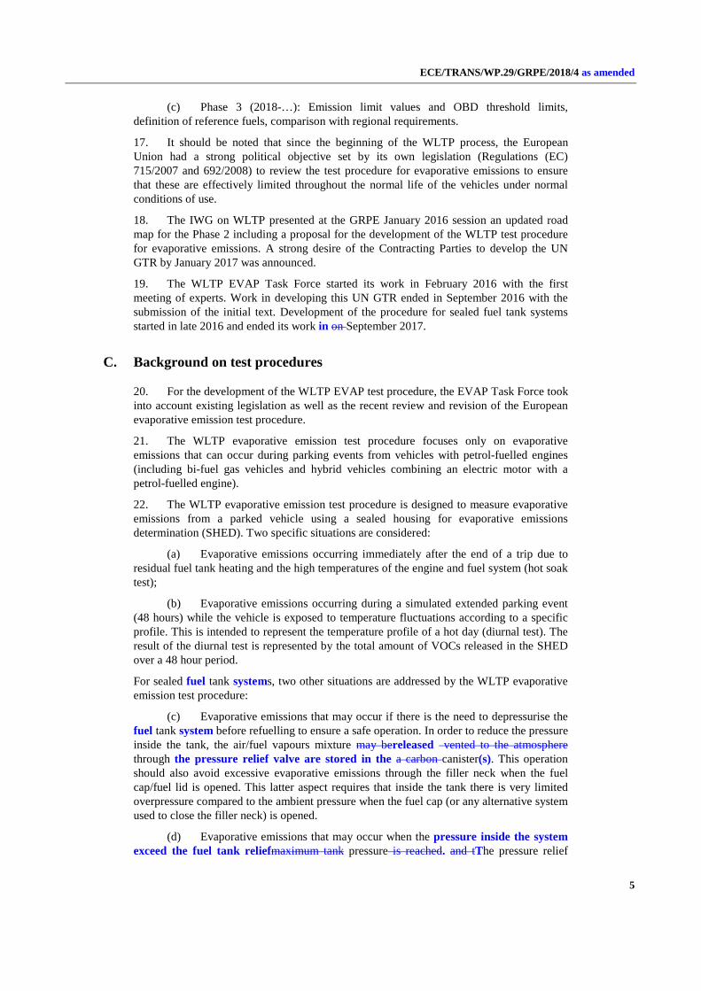
(c) Evaporative emissions that may occur if there is the need to depressurise the fuel tank system before refuelling to ensure a safe operation. In order to reduce the pressure inside the tank, the air/fuel vapours mixture may bereleased vented to the atmosphere through the pressure relief valve are stored in the a carbon canister(s). This operation should also avoid excessive evaporative emissions through the filler neck when the fuel cap/fuel lid is opened. This latter aspect requires that inside the tank there is very limited overpressure compared to the ambient pressure when the fuel cap (or any alternative system used to close the filler neck) is opened.
(d) Evaporative emissions that may occur when the pressure inside the system exceed the fuel tank reliefmaximum tank pressure is reached. and tThe pressure relief

ECE/TRANS/WP.29/GRPE/2018/4 as amended
6
valve opens to ensure safe operationavoid the risk of a rupture of the system. In these conditions the emissions could be uncontrolled in the case of a fully saturated canister. This has The test procedure has been taken in to account when developing the test proceduredesigned in order to reduce the frequency of this possibility or, alternatively, to control these emissions by means of the carbon canister.
23. The performance of the evaporative emission control system strongly depends on the initial condition of the carbon canister which is expected to adsorb the vapours generated in the tank. In order to simulate realistic conditions, prior to starting the hot soak and diurnal tests, the carbon canister is loaded to the breakthrough and then purged by driving the vehicle over a specific combination of WLTC sections (conditioning drive). The conditioning drive cycle was extensively assessed and discussed also on the basis of real world activity data to take into account that the most critical conditions are represented by short trips in urban areas. For this reason, the conditioning drive for Class 2 and 3 vehicles includes one low phase, two medium phases and one high phase. The extra-high phase was excluded. The conditioning drive for Class 1 vehicles includes four low phases, two medium phases.
24. The test procedure also includes specific provisions to take into account the potential deterioration of the evaporative emission control system efficiency especially in the presence of ethanol in the fuel. The evaporative emission test is carried out with a carbon canister aged both mechanically and chemically according to a specific procedure. In addition, a permeation factor is used to take into account the potential increase over time of the full permeation rate through the tank walls.
25. As far as the fuel is concerned, its vapour pressure and composition (especially ethanol content) have a large effect on evaporative emissions and need therefore to be clearly specified. However, due to regional differences in the market specifications of fuels and in the measurement methods of their relevant properties, regionally different reference fuels need to be recognised. Contracting Parties may select their reference fuels either according to Annex 3 to UN GTR No. 15 or according to Annex 2 of this UN GTR.
D. Technical feasibility, anticipated costs and benefits
26. In designing and validating the WLTP EVAP procedure, strong emphasis has been put on its practicability, which is ensured by a number of measures explained above.
27. In general, the WLTP EVAP test procedure has been defined taking into account the technology available for evaporative emission control as well as the existing test facilities.
28. The best available technology performance significantly exceeds the stricter requirements on evaporative emissions which will be introduced in some regions as a results of the adoption of the WLTP EVAP procedure. In general, compared to the technology needed to comply with the requirements based on the 24-hour diurnal test still in force in many regions, the additional cost per vehicle is considered quite limited and eventually compensated by the emission reduction and the fuel savings.
29. Performing a test according to the WLTP EVAP test procedure and complying with the emission limits should not represent a major issue in most cases. Since in many regions the current evaporative test procedure is based on the 24-hour diurnal test, limited upgrades to existing SHEDs might be required to run the 48-hour diurnal test. In other cases, additional SHEDs might be necessary to take into account the longer time needed to complete an evaporative emission tests. Nevertheless, 48-hour diurnal tests are already being performed by most of the car manufacturers since 48-hour and 72-hour diurnal test are already requested for some markets.

ECE/TRANS/WP.29/GRPE/2018/4 as amended
7
30. For a more accurate assessment, costs and benefits would have to be quantified on a regional level since they largely depend on the local conditions (climate, fleet composition, fuel quality, …).
31. As pointed out in the technical rationale and justification, the principle of a globally harmonized light duty vehicle test procedure offers potential cost reductions for vehicle manufacturers. The design of vehicles can be better unified on a global scale and administrative procedures may be simplified. The monetary quantification of these benefits depends largely on the extent and timing of implementations of the WLTP in regional legislation.

ECE/TRANS/WP.29/GRPE/2018/4 as amended
8
II. Text of the global technical regulation
1. Purpose
This global technical regulation (GTR) aims at providing a worldwide harmonized method to determine the levels of evaporative emission from light-duty vehicles in a repeatable and reproducible manner designed to be representative of real world vehicle operation. The results will provide the basis for the regulation of these vehicles within regional type approval and certification procedures.
2. Scope and application This UN GTR applies to vehicles of categories 1-2 and 2, both having a technically permissible maximum laden mass not exceeding 3,500 kg, with positive ignition engines with the exclusion of mono-fuel gas vehicles, and to all vehicles of category 1-1 with positive ignition engines with the exclusion of mono-fuel gas vehicles.1
3. Definitions
3.1. Test equipment
3.1.1. "Accuracy" means the difference between a measured value and a reference value, traceable to a national standard and describes the correctness of a result.
3.1.2. "Calibration" means the process of setting a measurement system's response so that its output agrees with a range of reference signals.
3.2. Hybrid electric vehicles
3.2.1. "Charge-depleting operating condition" means an operating condition in which the energy stored in the Rechargeable Electric Energy Storage System (REESS) may fluctuate but decreases on average while the vehicle is driven until transition to charge-sustaining operation.
3.2.2. "Charge-sustaining operating condition" means an operating condition in which the energy stored in the REESS may fluctuate but, on average, is maintained at a neutral charging balance level while the vehicle is driven.
3.2.3. "Not off-vehicle charging hybrid electric vehicle" (NOVC-HEV) means a hybrid electric vehicle that cannot be charged from an external source.
3.2.4. "Off-vehicle charging hybrid electric vehicle" (OVC-HEV) means a hybrid electric vehicle that can be charged from an external source.
3.2.5. "Hybrid electric vehicle" (HEV) means a hybrid vehicle where one of the propulsion energy converters is an electric machine.
1 ECE/TRANS/WP.29/1045, as amended by Amends. 1 and 2 (Special Resolution No. 1,
www.unece.org/trans/main/wp29/wp29wgs/wp29gen/wp29resolutions.html)
ECE/TRANS/WP.29/GRPE/2018/4 as amended
9
3.2.6. "Hybrid vehicle" (HV) means a vehicle equipped with a powertrain containing at least two different categories of propulsion energy converters and at least two different categories of propulsion energy storage systems.
3.3. Evaporative emission
3.3.1. "Fuel tank system" means the devices which allow storing the fuel, comprising the fuel tank, the fuel filler, the filler cap and the fuel pump when it is fitted in or on the fuel tank.
3.3.2. "Fuel system" means the components which store or transport fuel on board the vehicle and comprise the fuel tank system, all fuel and vapour lines, any non-tank mounted fuel pumps and the activated carbon canister.
3.3.3. "Butane working capacity" (BWC) means the mass of butane which a canister can adsorb.
3.3.4. "BWC300" means the butane working capacity after 300 cycles of fuel ageing cycles experienced.
3.3.5. "Permeability Factor" (PF) means the factor determined from hydrocarbon losses over a period of time and used to determine the final evaporative emissions.
3.3.6. "Monolayer non-metal tank" means a fuel tank constructed with a single layer of non-metal material including fluorinated/sulfonated materials.
3.3.7. "Multilayer tank" means a fuel tank constructed with at least two different layered materials, one of which is a hydrocarbon barrier material.
3.3.8. "Sealed fuel tank system" means a fuel tank system where the fuel vapours do not vent during parking over the 24-hour diurnal cycle defined in Appendix 2 to Annex 7 to Regulation No. 83-07 when performed with a reference fuel defined in Annex 2 of this UN GTR.
3.3.9. "Evaporative emissions" means in the context of this UN GTR the hydrocarbon vapours lost from the fuel system of a motor vehicle during parking and immediately before refuelling of a sealed fuel tank.
3.3.10. "Mono-fuel gas vehicle" means a mono-fuel vehicle that runs primarily runs on liquefied petroleum gas, natural gas/biomethane, or hydrogen but may also have a petrol system for emergency purposes or starting only, where the petrol tank does not contain more than 15 litres of petrol.
3.3.11. "Depressurisation puff loss" means hydrocarbons venting from a sealed fuel tank system pressure relief exclusively through the vapour storage unit allowed by the system.
3.3.12. "Depressurisation puff loss overflow" are the depressurisation puff loss hydrocarbons that pass through the vapour storage unit during depressurisation.
3.3.13. "Fuel tank relief pressure" is the minimum pressure value at which the sealed fuel tank system starts venting in response only to pressure inside the tank.
3.3.14. "Auxiliary canister" is the canister used to measure depressurisation puff loss overflow.
3.3.15. "2 gram breakthrough" shall be considered accomplished when the cumulative quantity of hydrocarbons emitted from the activated carbon canister equals 2 grams.

ECE/TRANS/WP.29/GRPE/2018/4 as amended
10
4. Abbreviations
General abbreviations
BWC Butane working capacity
PF Permeability factor
APF Assigned permeability factor
OVC-HEV Off-vehicle charging hybrid electric vehicle
WLTC Worldwide light-duty test cycle
REESS Rechargeable electric energy storage system
5. General requirements
5.1. The vehicle and its components liable to affect the evaporative emissions shall be designed, constructed and assembled so as to enable the vehicle in normal use and under normal conditions of use such as humidity, rain, snow, heat, cold, sand, dirt, vibrations, wear, etc. to comply with the provisions of this UN GTR during its useful life determined by Contracting Parties.
5.1.1. This shall include the security of all hoses, joints and connections used within the evaporative emission control systems.
5.1.2. For vehicles with a sealed fuel tank system, this shall also include having a system which, just before refuelling, releases the tank pressure exclusively through a vapour storage unit which has the sole function of storing fuel vapour. This ventilation route shall also be the only one used when the tank pressure exceeds its safe working pressure.
5.2. The test vehicle shall be selected according to paragraph 5.5.2. of this UN GTR.
5.3. Vehicle testing condition
5.3.1. The types and amounts of lubricants and coolant for emissions testing shall be as specified for normal vehicle operation by the manufacturer.
5.3.2. The type of fuel for testing shall be as specified in Annex 2 to this UN GTR.
5.3.3. All evaporative emissions controlling systems shall be in working order.
5.3.4. The use of any defeat device is prohibited.
5.4. Provisions for electronic system security
5.4.1. Any vehicle with an evaporative emission control computer, including when integrated in an exhaust emissions control computer, shall include features to deter modification, except as authorised by the manufacturer. The manufacturer shall authorise modifications if these modifications are necessary for the diagnosis, servicing, inspection, retrofitting or repair of the vehicle. Any reprogrammable computer codes or operating parameters shall be resistant to tampering and afford a level of protection at least as good as the provisions in ISO 15031-7 (March 15, 2001). Any removable calibration memory chips shall be potted, encased in a sealed container or protected by electronic algorithms and shall not be changeable without the use of specialized tools and procedures.

ECE/TRANS/WP.29/GRPE/2018/4 as amended
11
5.4.2. Computer-coded engine operating parameters shall not be changeable without the use of specialized tools and procedures (e.g. soldered or potted computer components or sealed (or soldered) enclosures).
5.4.3. Manufacturers may seek approval from the responsible authority for an exemption to one of these requirements for those vehicles that are unlikely to require protection. The criteria that the responsible authority will evaluate in considering an exemption shall include, but are not limited to, the current availability of performance chips, the high-performance capability of the vehicle and the projected sales volume of the vehicle.
5.4.4. Manufacturers using programmable computer code systems shall deter unauthorised reprogramming. Manufacturers shall include enhanced tamper protection strategies and write-protect features requiring electronic access to an off-site computer maintained by the manufacturer. Methods giving an adequate level of tamper protection will be approved by the responsible authority.
5.5. Evaporative emission family
5.5.1. Only vehicles that are identical with respect to the following characteristics listed in (a) to (d) and are similar or, where applicable, within the stated tolerance regarding the characteristics listed in (e) and (f) may be part of the same evaporative emission family:
(a) Fuel tank system material and construction;
(b) Vapour hose material, fuel line material and connection technique;
(c) Sealed tank or non-sealed tank system;
(d) Fuel tank relief valve setting (air ingestion and relief);
(e) Canister butane working capacity (BWC300) within a 10 per cent range of the highest value (for canisters with the same type of charcoal, the volume of charcoal shall be within 10 per cent of that for which the BWC300 was determined);
(f) Purge control system (for example, type of valve, purge control strategy).
5.5.2. The vehicle shall be considered to produce worst-case evaporative emissions and shall be used for testing if it has the largest ratio of fuel tank capacity to canister butane working capacity within the family. The vehicle selection shall be agreed in advance with the responsible authority.
5.5.3. The use of any innovative system calibration, configuration, or hardware related to the evaporative control system shall place the vehicle model in a different family.
5.6. The responsible authority shall not grant type approval if the information provided is insufficient to demonstrate that the evaporative emissions are effectively limited during the normal use of the vehicle.
6. Performance requirements
6.1. Limit values
The following limit values shall apply:

ECE/TRANS/WP.29/GRPE/2018/4 as amended
12
(a) For Contracting Parties which adopt the calculation defined in paragraph 7.2. of Annex 1, the limit value shall be 2.0 g/test;
(b) For Contracting Parties which adopt the alternative calculation defined in paragraph 7.3. of Annex 1, the limit value shall be determined by the Contracting Party.

ECE/TRANS/WP.29/GRPE/2018/4 as amended
13
Annex 1
Type 4 test procedures and test conditions
1. Introduction
This annex describes the procedure for the Type 4 test which determines the evaporative emission of vehicles.
2. Technical requirements
2.1. The procedure includes the evaporative emissions test and two additional tests, one for the ageing of carbon canisters, as described in paragraph 5.1. of this annex, and one for the permeability of the fuel tank system, as described in paragraph 5.2. of this annex. The evaporative emissions test (Figure A1/4) determines hydrocarbon evaporative emissions as a consequence of diurnal temperature fluctuations and hot soaks during parking.
2.2. In the case that the fuel system contains more than one carbon canister, all references to the term "canister" in this UN GTR will apply to each canister.
3. Vehicle
The vehicle shall be in good mechanical condition and have been run-in and driven at least 3,000 km before the test. For the purpose of the determination of evaporative emissions, the mileage and the age of the vehicle used for certification shall be recorded. The evaporative emission control system shall be connected and functioning correctly during the run-in period. A carbon canister aged according to the procedure described in paragraph 5.1. of this annex shall be used.
4. Test equipment
4.1. Chassis dynamometer
The chassis dynamometer shall meet the requirements of paragraph 2. of Annex 5 to UN GTR No. 15.
4.2. Evaporative emission measurement enclosure
The evaporative emission measurement enclosure shall meet the requirements of paragraph 4.2. of Annex 7 to the 07 series of amendments to Regulation No. 83 (Regulation No. 83-07).
4.3. Analytical systems
The analytical systems shall meet the requirements of paragraph 4.3. of Annex 7 to Regulation No. 83-07. Continuous measuring of hydrocarbons is not mandatory unless the fixed volume type enclosure is used.
4.4. Temperature recording system
The temperature recording shall meet the requirements of paragraph 4.5. of Annex 7 to Regulation No. 83-07.
4.5. Pressure recording system
The pressure recording shall meet the requirements of paragraph 4.6. of Annex 7 to Regulation No. 83-07, except that the accuracy and resolution of
ECE/TRANS/WP.29/GRPE/2018/4 as amended
14
the pressure recording system defined in paragraph 4.6.2. of Annex 7 to Regulation No. 83-07 shall be:
(a) Accuracy: ±0.3 kPa
(b) Resolution: 0.025 kPa
4.6. Fans
The fans shall meet the requirements of paragraph 4.7. of Annex 7 to Regulation No. 83-07, except that the capacity of the blowers shall be 0.1 to 0.5 m³/sec instead of 0.1 to 0.5 m³/min.
4.7. Calibration gases
The gases shall meet the requirements of paragraph 4.8. of Annex 7 to Regulation No. 83-07.
4.8. Additional Equipment
The additional equipment shall meet the requirements of paragraph 4.9. of Annex 7 to Regulation No. 83-07.
4.9. Auxiliary canister
The auxiliary canister should be identical to the main canister but not necessarily aged. The connection tube to the vehicle canister shall be as short as possible. The auxiliary canister shall be fully-purged with dry air prior to loading.
4.10. Canister weighing scale
The canister weighing scale shall have an accuracy of ±0.02 g.
5. Procedure for canister bench ageing and PF determination
5.1. Canister bench ageing
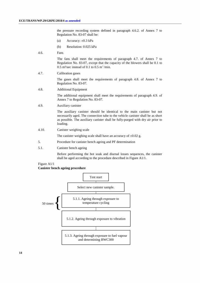
Before performing the hot soak and diurnal losses sequences, the canister shall be aged according to the procedure described in Figure A1/1.
Figure A1/1 Canister bench ageing procedure
Test start
Select new canister sample.
5.1.1. Ageing through exposure to temperature cycling
5.1.2. Ageing through exposure to vibration
5.1.3. Ageing through exposure to fuel vapour and determining BWC300
{ 50 times

ECE/TRANS/WP.29/GRPE/2018/4 as amended
15
5.1.1. Ageing through exposure to temperature cycling
The canister shall be cycled between temperatures from -15 °C to 60 °C in a dedicated temperature enclosure with 30 minutes of stabilisation at -15 °C and 60 °C. Each cycle shall last 210 minutes (see Figure A1/2).
The temperature gradient shall be as close as possible to 1 °C/min. No forced air flow should pass through the canister.
The cycle shall be repeated 50 times consecutively. In total, this procedure lasts 175 hours.
Figure A1/2 Temperature conditioning cycle
5.1.2. Ageing through exposure to vibration
Following the temperature ageing procedure, the canister shall be shaken vertically with the canister mounted as per its orientation in the vehicle with an overall Grms > 1.5 m/sec2 with a frequency of 30 ±10 Hz. The test shall last 12 hours.
5.1.3. Ageing through exposure to fuel vapour and determining BWC300
5.1.3.1. Ageing shall consist of repeatedly loading with fuel vapour and purging with laboratory air.
5.1.3.1.1. After temperature and vibration ageing, the canister shall be further aged with a mixture of market fuel as specified in paragraph 5.1.3.1.1.1. of this annex and nitrogen or air with a 50 ±15 per cent fuel vapour volume. The fuel vapour fill rate shall be 60 ±20 g/h.
The canister shall be loaded to 2 gram- breakthrough. As an alternative, loading shall be deemed to be completed when the hydrocarbon concentration level at the vent outlet reaches 3,000 ppm.
5.1.3.1.1.1. The market fuel used for this test shall fulfil the same requirements as a reference fuel with respect to:
(a) Density at 15 °C;
(b) Vapour pressure;
(c) Distillation (70 °C, 100 °C, 150 °C);
(d) Hydrocarbon analysis (olefins, aromatics, benzene only);
ECE/TRANS/WP.29/GRPE/2018/4 as amended
16
(e) Oxygen content;
(f) Ethanol content.
5.1.3.1.2. The canister shall be purged between 5 and 60 minutes after loading with 25 ±5 litres per minute of emission laboratory air until 300 bed volume exchanges are reached.
5.1.3.1.3. The procedures set out in paragraphs 5.1.3.1.1. and 5.1.3.1.2. of this annex shall be repeated 300 times after which the canister shall be considered to be stabilised.
5.1.3.1.4. The procedure to measure the butane working capacity (BWC) with respect to the evaporative emission family in paragraph 5.5. of this UN GTR shall consist of the following.
(a) The stabilised canister shall be loaded to 2 gram breakthrough and subsequently purged a minimum of 5 times. Loading shall be performed with a mixture composed of 50 per cent butane and 50 per cent nitrogen by volume at a rate of 40 grams butane per hour.
(b) Purging shall be performed according to paragraph 5.1.3.1.2. of this annex.
(c) The BWC shall be recorded after each loading.
(d) BWC300 shall be calculated as the average of the last 5 BWCs.
5.1.3.2. If an aged canister is provided by a supplier, the manufacturer shall inform the responsible authority in advance of the ageing process to enable the witnessing of any part of that process in the supplier’s facilities.
5.1.3.3. The manufacturer shall provide the responsible authority a test report including at least the following elements:
(a) Type of activated carbon;
(b) Loading rate;
(c) Fuel specifications.
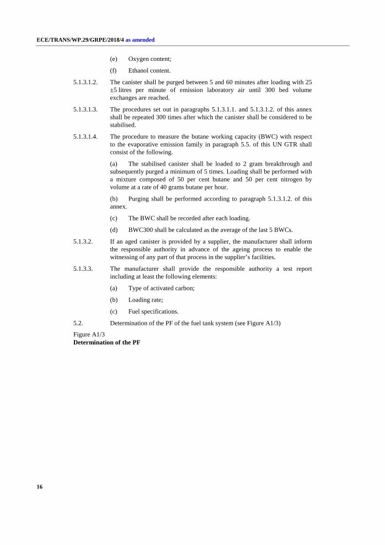
5.2. Determination of the PF of the fuel tank system (see Figure A1/3)
Figure A1/3 Determination of the PF

ECE/TRANS/WP.29/GRPE/2018/4 as amended
17
5.2.1. The fuel tank system representative of a family shall be selected and mounted on a rig in a similar orientation as in the vehicle. The tank shall be filled to 40 ±2 per cent of its nominal capacity with reference fuel at a temperature of 18 °C ±2 °C. The rig with the fuel tank system shall be placed in a room with a controlled temperature of 40 °C ±2 °C for 3 weeks.
5.2.2. At the end of the third week, the tank shall be drained and refilled with reference fuel at a temperature of 18 °C ±2 °C to 40 ±2 per cent of its nominal tank capacity.
Within 6 to 36 hours, the rig with the fuel tank system shall be placed in an enclosure. The last 6 hours of this period shall be at an ambient temperature of 20 °C ±2 °C. In the enclosure, a diurnal procedure shall be performed over
Test start
5.2.1. Fill the tank to 40 ±2 per cent of its nominal capacity with reference fuel
5.2.1. Soak for 3 weeks at 40 °C ±2 °C
5.2.2. Measurement of HC in the same conditions as for the 1st day of diurnal emission test:
HC3w
5.2.3. Soak for the remaining 17 weeks at 40 °C ±2 °C
5.2.4. Measurement of HC in the same conditions as for the 1st day of diurnal emission test:
HC20w
5.2.5. Permeability Factor = HC20w - HC3w
5.2.2. Drain and fill the tank to 40 per cent of its nominal capacity with reference fuel
5.2.4. Drain and fill the tank to 40 per cent of its nominal capacity with reference fuel

ECE/TRANS/WP.29/GRPE/2018/4 as amended
18
the first 24-hour period of the procedure described in paragraph 6.5.109. of this annex. The fuel vapour in the tank shall be vented to the outside of the enclosure to eliminate the possibility of the tank venting emissions being counted as permeation. The HC emissions shall be measured and the value shall be recorded as HC3W.
5.2.3. The rig with the fuel tank system shall be placed again in a room with a controlled temperature of 40 °C ±2 °C for the remaining 17 weeks.
5.2.4. At the end of the seventeenth week, the tank shall be drained and refilled with reference fuel at a temperature of 18 °C ±2 °C to 40 ±2 per cent of its nominal tank capacity.
Within 6 to 36 hours, the rig with the fuel tank system shall be placed in an enclosure. The last 6 hours of this period shall be at an ambient temperature of 20 °C ±2 °C. In the enclosure, a diurnal procedure shall be performed over a first period of 24 hours of the procedure described according to paragraph 6.5.109. of this annex. The fuel tank system shall be vented to the outside of the enclosure to eliminate the possibility of the tank venting emissions being counted as permeation. The HC emissions shall be measured and the value shall be recorded in this case as HC20W.
5.2.5. The PF is the difference between HC20W and HC3W in g/24h calculated to 3 significant digits using the following equation:
PF = HC20w − HC3W
5.2.6. If the PF is determined by a supplier, the vehicle manufacturer shall inform the responsible authority in advance of the determination to allow witness check in the supplier’s facility.
5.2.7. The manufacturer shall provide the responsible authority with a test report containing at least the following:
(a) A full description of the fuel tank system tested, including information on the type of tank tested, whether the tank is metal, monolayer non-metal or multilayer, and which types of materials are used for the tank and other parts of the fuel tank system;
(b) The weekly mean temperatures at which the ageing was performed;
(c) The HC measured at week 3 (HC3W);
(d) The HC measured at week 20 (HC20W);
(e) The resulting permeability factor (PF).
5.2.8. As an alternative exception to paragraphs 5.2.1. to 5.2.7. inclusive of this annex, a manufacturer using multilayer tanks or metal tanks may choose to use an APF instead of performing the complete measurement procedure mentioned above:
APF multilayer/metal tank = 120 mg /24 h
Where the manufacturer chooses to use an APF, the manufacturer shall provide the responsible authority with a declaration in which the type of tank is clearly specified as well as a declaration of the type of materials used.
6. Test procedure for the measurement of hot soak and diurnal losses
6.1. Vehicle preparation

ECE/TRANS/WP.29/GRPE/2018/4 as amended
19
The vehicle shall be prepared in accordance to paragraphs 5.1.1. and 5.1.2. of Annex 7 to Regulation No. 83-07. At the request of the manufacturer and with approval of the responsible authority, non-fuel background emission sources (e.g. paint, adhesives, plastics, fuel/vapour lines, tyres, and other rubber or polymer components) may be reduced to typical vehicle background levels before testing (e.g. baking of tyres at temperatures of 50 °C or higher for appropriate periods, baking of the vehicle, draining washer fluid).
For a sealed fuel tank system, the vehicle canisters shall be installed so that access to canisters and connection/disconnection of canisters can be done easily.
6.2. Mode selections and gear shift prescriptions
6.2.1. For vehicles with manual shift transmissions, the gear shift prescriptions specified in Annex 2 to UN GTR No. 15 shall apply.
6.2.2. In the case of conventional ICE vehicles, the mode shall be selected according to Annex 6 to UN GTR No. 15.
6.2.3. In the case of NOVC-HEVs and OVC-HEVs, the mode shall be selected according to Appendix 6 to Annex 8 of UN GTR No. 15.
6.2.4. Upon request of the responsible authority, the selected mode may be different from that described in paragraphs 6.2.2. and 6.2.3. of this annex.
6.3. Test conditions
The tests included in this UN GTR shall be performed using the test conditions specific to the interpolation family vehicle H with the highest cycle energy demand of all the interpolation families included in the evaporative emission family being considered.
Otherwise, at the request of the responsible authority, any cycle energy representative of a vehicle in the family may be used for the test.
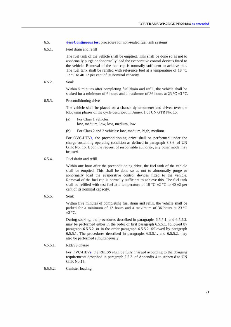
6.4. Flow of the test procedure
The test procedure for non-sealed and sealed tank systems shall be followed according to the flow chart described in Figure A1/4.
The sealed fuel tank systems shall be tested with 2 options. One option is to test the vehicle with one continuous procedure. Another option, called the stand-alone procedure, is to test the vehicle with two separate procedures which will allow to repeating the dynamometer test and the diurnal tests without repeating the tank depressurisation puff loss overflow test and the depressurisation puff loss measurement.

ECE/TRANS/WP.29/GRPE/2018/4 as amended
20
Figure A1/4 Test procedure flow charts Flow of the test procedure
Start for: Non Non-sealed fuel tanks, sealed fuel tanks continuous and sealed fuel tanks stand-alone puff
6.5.1. Fuel drain and refill to 40 %
6.5.2. Soak for 6 to 36 hours @ 23 °C
6.5.3. Preconditioning drive
Start for: Sealed fuel tanks, stand-alone hot soak and diurnals
6.6.1.3. Soak for 6 to 36 hours @ 20°C 6.6.1.4. Fuel tank pressure relief
6.5.6. Dynamometer test
Start hot soak test within 7 minutes after dynamometer test and 2 minutes after engine being
switched off
6.5.7. Hot soak test: MHS
6.5.8. Soak for 6 to 36 hours @ 20 °C
6.5.9. 1st day diurnal: MD1
6.5.9. 2nd
day diurnal: MD2
7. Calculations
End
6.6.1.2. Fuel drain and refill to 15 %
6.5.5. Soak for 12 to 36 hours @ 23 °C
6.6.1.5. Load aged canister to 2 g breakthrough
6.6.1.5. Canister purge 85 % fuel consumption equivalent
6.6.1.6. Preparation of canister depressurisation puff loss loading
(11-hour temperature cycle)
6.6.1.7.2. Puff loss loading
6.6.1.8. Measurement of puff loss overflow
End of stand-alone puff loss test
6.6.1.9. Soak for 6 to 36 hours @ 23 °C 6.6.1.9.1. Charge OVC-HEV
6.6.1.10. Fuel drain and refill to
40 %
6.6.1.11. Soak for 6 to 36 hours @ 20 °C
6.6.1.12. Fuel tank depressurisation with canister disconnected
6.5.1. Fuel drain and refill to 40 %
6.5.2. Soak for 6 to 36 hours @ 23 °C
6.5.3. Preconditioning drive
6.6.1.9. Soak for 6 to 36 hours @ 23 °C
6.6.1.9.1. Charge OVC-HEV REESS
6.6.1.5. Load aged canister to
2 g breakthrough
6.6.1.5. Canister purge 85 % fuel
consumption equivalent
6.7.2.1.3. Canister loading
with puff loss simulated mass
6.5.4. Fuel drain and refill to 40 %
Start next fuel drain and refill within 1 hour
Start next soak within 5 minutes
Start next fuel drain and refill within 1 hour
Start next soak within 5 minutes Start next soak within 5 minutes
Start puff loss loading within
15 minutes
Start next soak within 5 minutes
Yes
No Sealed fuel tank system?
6.5.5.1. Charge OVC-HEV
REESS
6.5.5.2. Load aged canister to
2 g breakthrough
ECE/TRANS/WP.29/GRPE/2018/4 as amended
21
6.5. Test Continuous test procedure for non-sealed fuel tank systems
6.5.1. Fuel drain and refill
The fuel tank of the vehicle shall be emptied. This shall be done so as not to abnormally purge or abnormally load the evaporative control devices fitted to the vehicle. Removal of the fuel cap is normally sufficient to achieve this. The fuel tank shall be refilled with reference fuel at a temperature of 18 °C ±2 °C to 40 ±2 per cent of its nominal capacity.
6.5.2. Soak
Within 5 minutes after completing fuel drain and refill, the vehicle shall be soaked for a minimum of 6 hours and a maximum of 36 hours at 23 °C ±3 °C.
6.5.3. Preconditioning drive
The vehicle shall be placed on a chassis dynamometer and driven over the following phases of the cycle described in Annex 1 of UN GTR No. 15:
(a) For Class 1 vehicles: low, medium, low, low, medium, low
(b) For Class 2 and 3 vehicles: low, medium, high, medium.
For OVC-HEVs, the preconditioning drive shall be performed under the charge-sustaining operating condition as defined in paragraph 3.3.6. of UN GTR No. 15. Upon the request of responsible authority, any other mode may be used.
6.5.4. Fuel drain and refill
Within one hour after the preconditioning drive, the fuel tank of the vehicle shall be emptied. This shall be done so as not to abnormally purge or abnormally load the evaporative control devices fitted to the vehicle. Removal of the fuel cap is normally sufficient to achieve this. The fuel tank shall be refilled with test fuel at a temperature of 18 °C ±2 °C to 40 ±2 per cent of its nominal capacity.
6.5.5. Soak
Within five minutes of completing fuel drain and refill, the vehicle shall be parked for a minimum of 12 hours and a maximum of 36 hours at 23 °C ±3 °C.
During soaking, the procedures described in paragraphs 6.5.5.1. and 6.5.5.2. may be performed either in the order of first paragraph 6.5.5.1. followed by paragraph 6.5.5.2. or in the order paragraph 6.5.5.2. followed by paragraph 6.5.5.1. The procedures described in paragraphs 6.5.5.1. and 6.5.5.2. may also be performed simultaneously.
6.5.5.1. REESS charge
For OVC-HEVs, the REESS shall be fully charged according to the charging requirements described in paragraph 2.2.3. of Appendix 4 to Annex 8 to UN GTR No.15.
6.5.5.2. Canister loading

ECE/TRANS/WP.29/GRPE/2018/4 as amended
22
The canister aged according to the sequence described in paragraph 5.1. of this annex shall be loaded to 2 gram breakthrough according to the procedure described in paragraph 5.1.4. of Annex 7 to Regulation No. 83-07.
6.5.6. Dynamometer test
The test vehicle shall be pushed onto a dynamometer and shall be driven over the cycles described in paragraph 6.5.3.(a) or paragraph 6.5.3.(b) of this annex. OVC-HEVs shall be operated in charge-depleting operating condition. The engine shall be subsequently shut off. Exhaust emissions may be sampled during this operation and the results may be used for the purpose of exhaust emission and fuel consumption type approval if this operation meets the requirement described in Annex 6 or Annex 8 of UN GTR No.15.
6.5.7. Hot soak evaporative emissions test
Within 7 minutes after the dynamometer test and within 2 minutes of the engine being switched off, the hot soak evaporative emissions test shall be performed in accordance to paragraph 5.5. of Annex 7 to Regulation No. 83-07. The hot soak losses shall be calculated according to paragraph 7.1. of this annex and recorded as MHS.
6.5.8. Soak
After the hot soak evaporative emissions test, the test vehicle shall be soaked for not less than 6 hours and not more than 36 hours between the end of the hot soak test and the start of the diurnal emission test. For at least the last 6 hours of this period the vehicle shall be soaked at 20 °C ±2 °C.
6.5.9. Diurnal testing
6.5.9.1. The test vehicle shall be exposed to two cycles of ambient temperature according to the profile specified for the diurnal emission test in Appendix 2 to Annex 7 to Regulation No. 83-07 with a maximum deviation of ±2 °C at any time. The average temperature deviation from the profile, calculated using the absolute value of each measured deviation, shall not exceed ±1 °C. Ambient temperature shall be measured and recorded at least every minute. Temperature cycling shall begin at time Tstart = 0, as specified in paragraph 6.5.109.6. of this annex.
6.5.9.2. The enclosure shall be purged for several minutes immediately before the test until a stable background is obtained. The chamber mixing fan(s) shall also be switched on at this time.
6.5.9.3. The test vehicle, with the powertrain shut off and the test vehicle windows and luggage compartment(s) opened, shall be moved into the measuring chamber. The mixing fan(s) shall be adjusted in such a way as to maintain a minimum air circulation speed of 8 km/h under the fuel tank of the test vehicle.
6.5.9.4. The hydrocarbon analyser shall be zeroed and spanned immediately before the test.
6.5.9.5. The enclosure doors shall be closed and sealed gas-tight.
6.5.9.6. Within 10 minutes of closing and sealing the doors, the hydrocarbon concentration, temperature and barometric pressure shall be measured to give initial readings of hydrocarbon concentration in the enclosure CHCi, barometric pressure Pi and ambient chamber temperature Ti for the diurnal testing. Tstart = 0 starts at this time.
ECE/TRANS/WP.29/GRPE/2018/4 as amended
23
6.5.9.7. The hydrocarbon analyser shall be zeroed and spanned immediately before the end of each emission sampling period.
6.5.9.8. The end of the first and second emission sampling period shall occur at 24 hours ±6 minutes and 48 hours ±6 minutes, respectively, after the beginning of the initial sampling, as specified in paragraph 6.5.119.6. of this annex. The elapsed time shall be recorded.
At the end of each emission sampling period, the hydrocarbon concentration, temperature and barometric pressure shall be measured and used to calculate the diurnal test results using the equation in paragraph 7.1. of this annex. The result obtained from the first 24 hours shall be recorded as MD1. The result obtained from the second 24 hours shall be recorded as MD2.
6.6. Continuous test procedure for sealed fuel tank systems
6.6.1. In the case that the fuel tank relief pressure is greater than or equal to 30 kPa
6.6.1.1. The test shall be performed as described in paragraphs 6.5.1. to 6.5.3. inclusive of this annex.
6.6.1.2. Fuel drain and refill
Within one hour after the preconditioning drive, the fuel tank of the vehicle shall be emptied. This shall be done so as not to abnormally purge or abnormally load the evaporative control devices fitted to the vehicle. Removal of the fuel cap is normally sufficient to achieve this, otherwise the canister shall be disconnected. The fuel tank shall be refilled with reference fuel at a temperature of 18 °C ±2 °C to 15 ±2 per cent of the tank's nominal capacity.
6.6.1.3. Soak
Within 5 minutes after completing fuel drain and refill, the vehicle shall be soaked for stabilization for 6 to 36 hours at an ambient temperature of 20 °C ±2 °C.
6.6.1.4. Fuel tank depressurisation
The tank pressure shall be subsequently released so as not to abnormally raise the inside pressure of the fuel tank. This may be done by opening the fuel cap of the vehicle. Regardless of the method of depressurisation, the vehicle shall be returned to its original condition within 1 minute.
6.6.1.5. Canister loading and purge
The canister aged according to the sequence described in paragraph 5.1. of this annex shall be loaded to 2 gram- breakthrough according to the procedure described in paragraph 5.1.6. of Annex 7 of UN/ECE Regulation No. 83-07, and shall be subsequently purged with 25 ±5 litres per minute with emission laboratory air. The volume of purge air shall not exceed the volume defined in paragraph 6.6.1.5.1. This loading and purging can be done either (a) using an on-board canister under either at a temperature of the 20 °C or optionally 23 °C, or (b) by disconnecting the canister. In both cases, no further relief of the tank pressure is allowed.
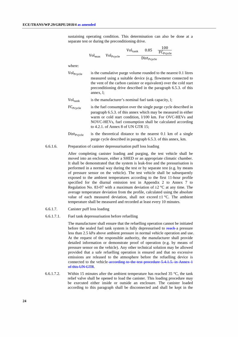
6.6.1.5.1. Determination of maximum purge volume
The maximum purge amount Volmax shall be determined by the following equation. In the case of OVC-HEVs, the vehicle shall be operated in charge-
ECE/TRANS/WP.29/GRPE/2018/4 as amended
24
sustaining operating condition. This determination can also be done at a separate test or during the preconditioning drive.
Volmax = VolPcycle × Voltank × 0.85 × 100
FCPcycleDistPcycle
where:
VolPcycle is the cumulative purge volume rounded to the nearest 0.1 litres measured using a suitable device (e.g. flowmeter connected to the vent of the carbon canister or equivalent) over the cold start preconditioning drive described in the paragraph 6.5.3. of this annex, l;
Voltank is the manufacturer’s nominal fuel tank capacity, l;
FCPcycle is the fuel consumption over the single purge cycle described in paragraph 6.5.3. of this annex which may be measured in either warm or cold start condition, l/100 km. For OVC-HEVs and NOVC-HEVs, fuel consumption shall be calculated according to 4.2.1. of Annex 8 of UN GTR 15;
DistPcycle is the theoretical distance to the nearest 0.1 km of a single purge cycle described in paragraph 6.5.3. of this annex, km.
6.6.1.6. Preparation of canister depressurisation puff loss loading
After completing canister loading and purging, the test vehicle shall be moved into an enclosure, either a SHED or an appropriate climatic chamber. It shall be demonstrated that the system is leak-free and the pressurisation is performed in a normal way during the test or by separate test (e.g. by means of pressure sensor on the vehicle). The test vehicle shall be subsequently exposed to the ambient temperatures according to the first 11-hour profile specified for the diurnal emission test in Appendix 2 to Annex 7 to Regulation No. 83-07 with a maximum deviation of ±2 °C at any time. The average temperature deviation from the profile, calculated using the absolute value of each measured deviation, shall not exceed ±1 °C. The ambient temperature shall be measured and recorded at least every 10 minutes.
6.6.1.7. Canister puff loss loading
6.6.1.7.1. Fuel tank depressurisation before refuelling
The manufacturer shall ensure that the refuelling operation cannot be initiated before the sealed fuel tank system is fully depressurised to reach a pressure less than 2.5 kPa above ambient pressure in normal vehicle operation and use. At the request of the responsible authority, the manufacturer shall provide detailed information or demonstrate proof of operation (e.g. by means of pressure sensor on the vehicle). Any other technical solution may be allowed provided that a safe refuelling operation is ensured and that no excessive emissions are released to the atmosphere before the refuelling device is connected to the vehicle according to the test procedure 5.4.1.5. in Annex 1 of this UN GTR.
6.6.1.7.2. Within 15 minutes after the ambient temperature has reached 35 °C, the tank relief valve shall be opened to load the canister. This loading procedure may be executed either inside or outside an enclosure. The canister loaded according to this paragraph shall be disconnected and shall be kept in the
ECE/TRANS/WP.29/GRPE/2018/4 as amended
25
soak area. A dummy canister shall be installed to the vehicle when undertaking the procedure specified in paragraphs 6.6.1.8. to 6.6.1.12. inclusive of this annex.
6.6.1.8. Measurement of depressurisation puff loss overflow
6.6.1.8.1. Any depressurisation puff loss overflow from the vehicle canister shall be measured by using an auxiliary carbon canister connected directly at the outlet of the vehicle vapour storage unit. It shall be weighed before and after the procedure described in paragraph 6.6.1.7. of this annex.
6.6.1.8.2. Alternatively, the depressurisation puff loss overflow from the vehicle canister during its depressurisation may be measured using a SHED.
Within 15 minutes after the ambient temperature has reached 35°C as described in 6.6.1.7.2. of this annex, the chamber shall be sealed and the measurement procedure shall be started.
The hydrocarbon analyser shall be zeroed and spanned, after which the hydrocarbon concentration, temperature and barometric pressure shall be measured to give the initial readings CHCi, Pi and Ti for the sealed tank depressurisation puff loss overflow determination.
The ambient temperature T of the enclosure shall not be less than 25°C during the measurement procedure.
At the end of the procedure described in paragraph 6.6.1.6. of this annex, the hydrocarbon concentration in the chamber shall be measured after 60 ± 5 seconds. The temperature and the barometric pressure shall also be measured. These are the final readings CHCf, Pf and Tf for the sealed tank depressurisation puff loss overflow.
The sealed tank puff loss overflow result shall be calculated according to paragraph 7.1. of this annex and recorded.
6.6.1.8.3. There shall be no change in weight of the auxiliary canister or the result of the SHED measurement, within the tolerance of ± 0.5 gram.
6.6.1.9. Soak
After completing puff loss loading, the vehicle shall be soaked at 23 ±2 °C for 6 to 36 hours to stabilise the vehicle temperature.
6.6.1.9.1. REESS charge
For OVC-HEVs, the REESS shall be fully charged according to the charging requirements described in paragraph 2.2.3. of Appendix 4 to Annex 8 to UN GTR No.15 during the soaking described in paragraph 6.6.1.9. of this annex.
6.6.1.10. Third fuelFuel drain and refill
The fuel tank of the vehicle shall be drained and refilled up to 40 ±2 per cent of the tank's nominal capacity with reference fuel at a temperature of 18 °C ±2 °C.
6.6.1.11. Soak
The vehicle shall be subsequently parked for a minimum of 6 hours to a maximum of 36 hours in the soak area at 20 °C ±2 °C to stabilise the fuel temperature.
6.6.1.12. Fuel tank depressurisation

ECE/TRANS/WP.29/GRPE/2018/4 as amended
26
The tank pressure shall be subsequently released so as not to abnormally raise the inside pressure of the fuel tank. This may be done by opening the fuel cap of the vehicle. Regardless of the method of depressurisation, the vehicle shall be returned to its original condition within 1 minute. After this action, the vapour storage unit shall be connected again.
6.6.1.13. The procedures in paragraphs 6.5.6. to 6.5.9.8. inclusive of this annex shall be followed.
6.6.2. In the case that the fuel tank relief pressure is lower than 30 kPa
The test shall be performed as described in paragraphs 6.6.1.1. to 6.6.1.13. inclusive of this annex. However, in this case, the ambient temperature described in paragraph 6.5.9.1. of this annex shall be replaced by the profile specified in Table A1/1 of this annex for the diurnal emission test.
Table A1/1
Ambient temperature profile of the alternative sequence for sealed fuel tank system
Time (hours) Temperature (°C) 0/24 20.0
1 20.4 2 20.8 3 21.7 4 23.9 5 26.1 6 28.5 7 31.4 8 33.8 9 35.6
10 37.1 11 38.0 12 37.7 13 36.4 14 34.2 15 31.9 16 29.9 17 28.2 18 26.2 19 24.7 20 23.5 21 22.3 22 21.0 23 20.2
6.7. Stand-alone test procedure for sealed fuel tank systems
6.7.1 Measurement of depressurisation puff loss loading mass
6.7.1.1. The procedures in paragraphs 6.6.1.1. to 6.6.1.7.2. inclusive of this annex shall be performed. The depressurisation puff loss loading mass is defined as the difference in weight of the vehicle canister before paragraph 6.6.1.6. of this annex is applied and after paragraph 6.6.1.7.2.of this annex is applied.by the vehicle canister weight difference before paragraph 6.6.1.6. of this annex and after paragraph 6.6.1.7.2. of this annex.

ECE/TRANS/WP.29/GRPE/2018/4 as amended
27
6.7.1.2. The depressurisation puff loss overflow from the vehicle canister shall be measured according to paragraphs 6.6.1.8.1. and to 6.6.1.8.2. inclusive of this annex and fulfil the requirements of meet paragraph 6.6.1.8.3. in this annex.
6.7.2. Hot soak and diurnal breathing evaporative emissions test
6.7.2.1. In the case that the fuel tank relief pressure is greater than or equal to 30 kPa
6.7.2.1.1. The test shall be performed as described in paragraphs 6.5.1. to 6.5.3. and 6.6.1.9. to 6.6.1.9.1. inclusive of this annex.
6.7.2.1.2. The canister shall be aged according to the sequence described in paragraph 5.1. of this annex and shall be loaded and purged according to paragraph 6.6.1.5. of this annex.
6.7.2.1.3. The aged canister shall be subsequently loaded according to the procedure described in paragraph 5.1.6. of Annex 7 to Regulation No. 83-07 with the exemption of loading mass. Total loading mass shall be determined according to paragraph 6.7.1.1. of this annex. At the request of the manufacturer, the reference fuel may alternatively be used instead of butane. The canister shall be disconnected.
6.7.2.1.4. The procedures in paragraphs 6.6.1.10. to 6.6.1.13. inclusive of this annex shall be followed.
6.7.2.2. In the case that the fuel tank relief pressure is lower than 30 kPa
The test shall be performed as described in paragraphs 6.7.2.1.1. to 6.7.2.1.4. inclusive of this annex. However, in this case, the ambient temperature described in 6.5.9.1. of this annex shall be modified according to the profile specified in Table A1/1 of this annex for the diurnal emission test.
7. Calculation of evaporative test results
7.1. The evaporative emission tests described in this annex allow the hydrocarbon emissions from the puff loss overflow, diurnal and hot soak tests to be calculated. Evaporative losses from each of these tests shall be calculated using the initial and final hydrocarbon concentrations, temperatures and pressures in the enclosure, together with the net enclosure volume.
The following equation shall be used:
MHC= k × V × �CHCf×PfTf
− CHCi×PiTi
� + MHC,out − MHC,in
where:
MHC is the mass of hydrocarbons, grams;
MHC,out is the mass of hydrocarbons exiting the enclosure in the case of fixed volume enclosures for diurnal emission testing, grams;
MHC,in is the mass of hydrocarbon entering the enclosure in the case of fixed volume enclosures for diurnal emission testing, grams;
CHC is the measured hydrocarbon concentration in the enclosure, ppm volume in C1 equivalent;
V is the net enclosure volume corrected for the volume of the vehicle with the windows and the luggage compartment open, m3. If the volume of the vehicle is not known, a volume of 1.42 m3 shall be subtracted;

ECE/TRANS/WP.29/GRPE/2018/4 as amended
28
T is the ambient chamber temperature, in K;
P is the barometric pressure, kPa;
H/C is the hydrogen to carbon ratio and has the constant value of 2.33;
k is 1.2 × 10-4 × (12 + H/C), in (g × K/(m³ × kPa));
i is the initial reading;
f is the final reading;
7.2. The result of (MHS + MD1 + MD2 + (2 × PF)) shall be below the limit defined in paragraph 6.1.(a) of this UN GTR.
7.3. At the option of the Contracting Party, the following may be used:
The result of (MHS + MD_max + PF) shall be below the limit defined in paragraph 6.1.(b) of this UN GTR. The MD_max shall be either MD1 or MD2, whichever generates the higher emission.
8. Test report
The test report shall contain at least the following:
(a) Description of the soak periods, including time and mean temperatures;
(b) Description of aged canister used and reference to exact ageing report;
(c) Mean temperature during the hot soak test;
(d) Measurement during hot soak test, HSL;
(e) Measurement of first diurnal, DL1st day;
(f) Measurement of second diurnal, DL2nd day;
(g) Final evaporative test result, calculated according to paragraph 7. of this annex;
(h) Declared fuel tank relief pressure of the system (for sealed tank systems);
(i) Puff loss loading value (in the case that using stand-alone test described in paragraph 6.7. of this annex).
ECE/TRANS/WP.29/GRPE/2018/4 as amended
29
Annex 2
Reference fuels
1. As there are regional differences in the market specifications of fuels, regionally different reference fuels need to be recognised. Contracting Parties may select their reference fuels either according to Annex 3 to UN GTR No. 15. or according to paragraph 2. of this annex.
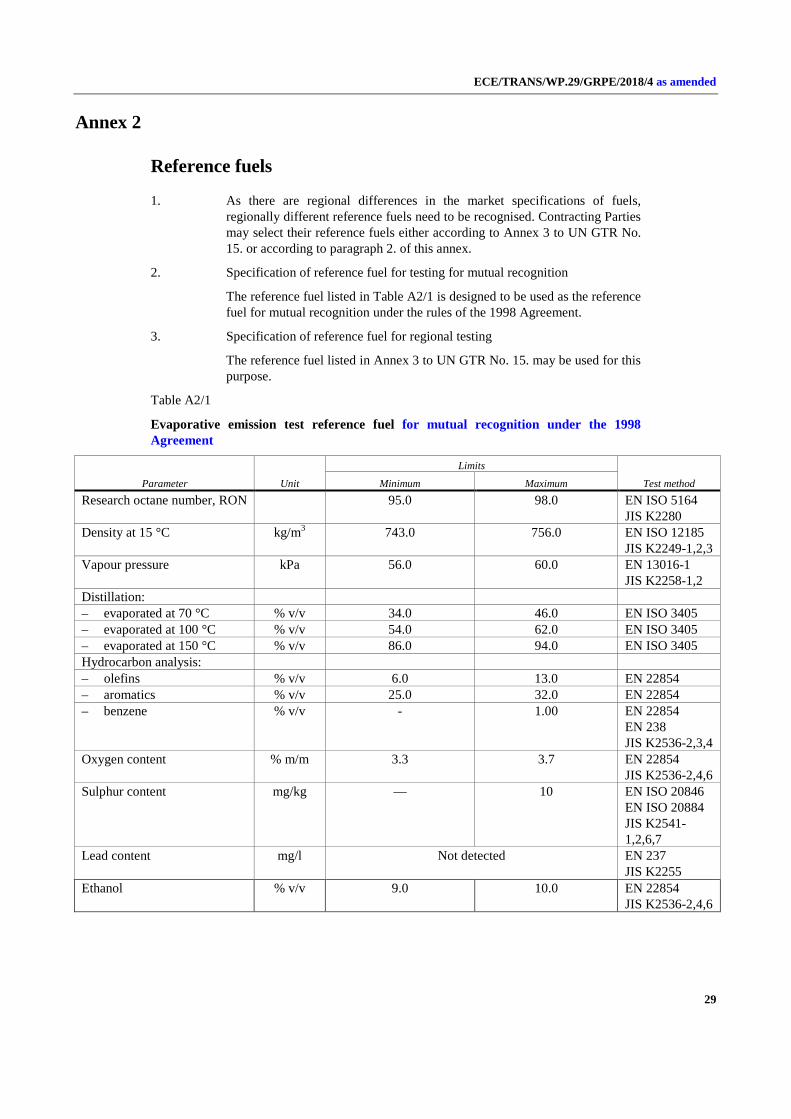
2. Specification of reference fuel for testing for mutual recognition
The reference fuel listed in Table A2/1 is designed to be used as the reference fuel for mutual recognition under the rules of the 1998 Agreement.
3. Specification of reference fuel for regional testing
The reference fuel listed in Annex 3 to UN GTR No. 15. may be used for this purpose.
Table A2/1
Evaporative emission test reference fuel for mutual recognition under the 1998 Agreement
Parameter Unit
Limits
Test method Minimum Maximum Research octane number, RON 95.0 98.0 EN ISO 5164
JIS K2280 Density at 15 °C kg/m3 743.0 756.0 EN ISO 12185
JIS K2249-1,2,3 Vapour pressure kPa 56.0 60.0 EN 13016-1
JIS K2258-1,2 Distillation: – evaporated at 70 °C % v/v 34.0 46.0 EN ISO 3405 – evaporated at 100 °C % v/v 54.0 62.0 EN ISO 3405 – evaporated at 150 °C % v/v 86.0 94.0 EN ISO 3405 Hydrocarbon analysis: – olefins % v/v 6.0 13.0 EN 22854 – aromatics % v/v 25.0 32.0 EN 22854 – benzene % v/v - 1.00 EN 22854
EN 238 JIS K2536-2,3,4
Oxygen content % m/m 3.3 3.7 EN 22854 JIS K2536-2,4,6
Sulphur content mg/kg — 10 EN ISO 20846 EN ISO 20884 JIS K2541-1,2,6,7
Lead content mg/l Not detected EN 237 JIS K2255
Ethanol % v/v 9.0 10.0 EN 22854 JIS K2536-2,4,6

ECE/TRANS/WP.29/GRPE/2018/4 as amended
30
Parameter Unit
Limits
Test method Minimum Maximum MTBE Not detected JIS K2536-
2,4,5,6(1) Methanol Not detected JIS K2536-
2,4,5,6(1) Kerosene Not detected JIS K2536-2,4(1) (1) Other method that is traceable to national or international standard may be used.