Property of Roger Cortesi, MIT Precision Engineering Research Group. DO NOT COPY or TRANSMIT without...
51
Property of Roger Cortesi, MIT Precision Engineering Research Group. DO NOT COPY or TRANSMIT without written permission. The Ceramic Samurai Ceramic Lathe Concepts by Roger Cortesi Alex Roger Precision Engineering Research Group Massachusetts Institute of Technology, Mechanical Engineering Department Phone: (518) 248-6923 Fax: (703) 991-5353 http://pergatory.mit.edu/ Room 3-470 77 Massachusetts Ave. Cambridge, MA 02139 [email protected] http://pergatory.mit.edu/rcortesi/
-
Upload
gabrielle-wimpey -
Category
Documents
-
view
213 -
download
0
Transcript of Property of Roger Cortesi, MIT Precision Engineering Research Group. DO NOT COPY or TRANSMIT without...

Property of Roger Cortesi, MIT Precision Engineering Research Group. DO NOT COPY or TRANSMIT without written permission.
The Ceramic Samurai
Ceramic Lathe Concepts by
Roger Cortesi Alex
Roger
Precision Engineering Research GroupMassachusetts Institute of Technology, Mechanical Engineering Department
Phone: (518) 248-6923Fax: (703) 991-5353
http://pergatory.mit.edu/
Room 3-47077 Massachusetts Ave.Cambridge, MA 02139
[email protected] http://pergatory.mit.edu/rcortesi/

Property of Roger Cortesi, MIT Precision Engineering Research Group. DO NOT COPY or TRANSMIT without written permission.
There are many unanswered questions.
Close collaboration with marketing and the customer will be required
What follows are our ideas. These could be used as a starting point…

Property of Roger Cortesi, MIT Precision Engineering Research Group. DO NOT COPY or TRANSMIT without written permission.
When designing a machine to grind ceramics there are two (2) major types.
Machines that grind parts that HAVE been fired.
and
Machines that grind parts that HAVE NOT been fired
Property of Roger Cortesi, MIT Precision Engineering Research Group. DO NOT COPY or TRANSMIT without written permission.
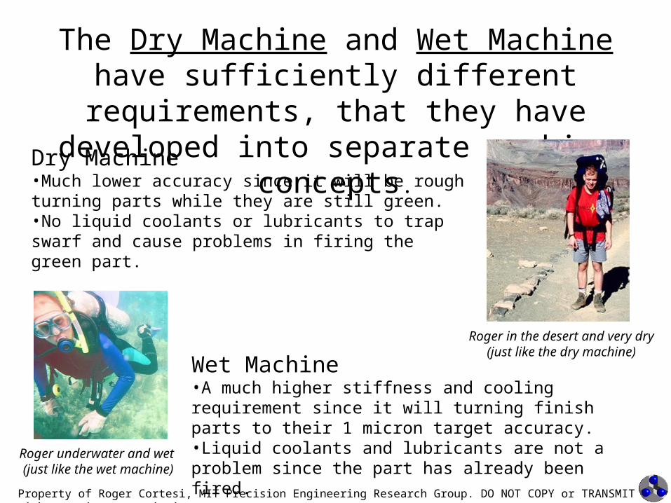
The Dry Machine and Wet Machine have sufficiently different requirements, that they
have developed into separate machine concepts.
Dry Machine•Much lower accuracy since it will be rough turning parts while they are still green.•No liquid coolants or lubricants to trap swarf and cause problems in firing the green part.
Wet Machine•A much higher stiffness and cooling requirement since it will turning finish parts to their 1 micron target accuracy.•Liquid coolants and lubricants are not a problem since the part has already been fired.Roger underwater and wet
(just like the wet machine)
Roger in the desert and very dry(just like the dry machine)

Property of Roger Cortesi, MIT Precision Engineering Research Group. DO NOT COPY or TRANSMIT without written permission.
We have ideas for both…
However, our instinct is that there is a larger market for machines that grind the finished part.
So we will stay focused on the wet machine for now.

Property of Roger Cortesi, MIT Precision Engineering Research Group. DO NOT COPY or TRANSMIT without written permission.
Basic Machine Requirements(this is our guess as to what the customer wants)
• Turn Ceramic Parts of up to 15” diameter and 12” long• Turn Ceramic Parts with a Maximum Weight of 100 kg• Turn Inside and Outside Diameters• Target Part Accuracy of 1 micron (0.00004”)• Target Cost of LESS THAN $50,000• Robust with respect to Ceramic Swarf• Minimal Assembly• Last ?????? Cycles (5? Years)

Property of Roger Cortesi, MIT Precision Engineering Research Group. DO NOT COPY or TRANSMIT without written permission.
Init
ial E
rror
Bud
get
Errorrms 0.923 mErrorrms MEwps2
MEwpc2 MEtps
2 MEtpc2 CEenc
2 TEstruc2
Errorsum 1.65 mErrorsum MEwps MEwpc MEtps MEtpc CEenc TEstruc
Total Machine Error:
Tallowed 0.205 KTallowedTEstruc
L
length of the machine structure we are concerned withL 12in
coefficient of thermal expantion for aluminum oxide 8m
m K
From this value we are able to determine the allowable change in machine temperature during machining operations.
maximum allowed thermal error.TEstruc 0.5m
Thermal Errors: These errors are due to the thermal contraction and expansion of the structure.
CEenc 0.75 mCEenc 3 resminControl errors are approximately 2 to 3 times encoder resolution.
minimum encoder resolutionresmin 0.25m
Control Errors: These errors are due mainly to the errors in the position encoders.
motion error in toolpiece carriage. This is assumed to be the amount of errors than can't be removed by mapping the controller.
MEtpc 0.1m
non-circularity motion error in toolpiece spindleMEtps 0.1m
motion error in workpeice carriage. This is assumed to be the amount of errors than can't be removed by mapping the controller.
MEwpc 0.1m
non-circularity motion error in workpiece spindleMEwps 0.1m
Motion Errors: These include errors in the bearings, straightness, and non-circularity of part/tool motion

Property of Roger Cortesi, MIT Precision Engineering Research Group. DO NOT COPY or TRANSMIT without written permission.
Concepts Considered for the Wet Machine

Property of Roger Cortesi, MIT Precision Engineering Research Group. DO NOT COPY or TRANSMIT without written permission.
Initial Double L Concept
Con’s•Low Natural Frequency•Potentially Very Heavy Structure•Alignment of Both Spindles w/ axis at
COM is tricky but possible
Pro’s•Excellent Access to Part and Spindles•Easy to Offer Multiple Configurations•Simple Structure

Property of Roger Cortesi, MIT Precision Engineering Research Group. DO NOT COPY or TRANSMIT without written permission.
Double “C” Concept
Con’s•Lower Natural Frequency•Potentially Very Heavy Structure•Alignment of Both Spindles w/ axis at COM is NOT possible
Pro’s•Excellent Access to Part and Spindles•Easy to Offer Multiple Configurations•Simple Structure

Property of Roger Cortesi, MIT Precision Engineering Research Group. DO NOT COPY or TRANSMIT without written permission.
Alternate Double L Concept
Con’s•Low Natural Frequency•Potentially Very Heavy Structure
Pro’s•Excellent Access to Part and Spindles•Easy to Offer Multiple Configurations•Simple Structure•Alignment of Both Spindles w/ axis at COM is possible

Property of Roger Cortesi, MIT Precision Engineering Research Group. DO NOT COPY or TRANSMIT without written permission.
“C” on Pipe Concept
Con’s•Low Natural Frequency•Potentially Very Heavy Structure•Complicated Structure
Pro’s•Excellent Access to Part and Spindles•Easy to Offer Multiple Configurations•Alignment of Both Spindles w/ axis at COM is possible

Property of Roger Cortesi, MIT Precision Engineering Research Group. DO NOT COPY or TRANSMIT without written permission.
The Pipe Lath Concept
It is difficult to get the 1st Non-Solid Body Mode greater than 200 Hz with the Double L structure.
This spawned the Pipe Lathe Concept
The minimal pipe lathe structure (left) showing the workpiece pipe and tool carriage half-pipe. The pipe lathe with stiffening members and support plates (right). Workpiece carriage motion
shown in blue-dashed arrow. Tool carriage motion shown in red-solid arrow.

Property of Roger Cortesi, MIT Precision Engineering Research Group. DO NOT COPY or TRANSMIT without written permission.
More Images of the Pipe Lathe
Grinding Wheel
Workpiece
Tool CarriageHydrobushing Rails
Workpiece Carriage Inside Pipe (not shown)
This finger necessary to allow grinding the inside surface

Property of Roger Cortesi, MIT Precision Engineering Research Group. DO NOT COPY or TRANSMIT without written permission.
Components

Property of Roger Cortesi, MIT Precision Engineering Research Group. DO NOT COPY or TRANSMIT without written permission.
Major Component Costs
Major Component Cost Estimates
Ballscrew Hardware 1,000$ per axisLinear Encoder 1,000$ per axisMotors 500$ per axisMotor Amp 500$ per axis
Per Axis Sub Total 3,000$
Hydrostatic Pump 3,000$ Grinding Spindle 8,000$ Workpiece Spindle 12,000$ CNC Controler 4,000$ Thermal Management Equipment 1,000$
Major Component Sub Total 34,000$
The machine structure is NOT included in these estimates

Property of Roger Cortesi, MIT Precision Engineering Research Group. DO NOT COPY or TRANSMIT without written permission.
Linear Guide SelectionSliding Bearings
•Cheapest•Ruined by Swarf•Standard Replacement Part
Rolling Element Trucks and Rails•Ruined by Swarf•High Stiffness•Standard Replacement Part
Aerostatic Bearings•Non affected by swarf•Low stiffness stiffness•Affected by coolant•Difficult to Replace (once installed)
Hydrostatic Bearings•Unaffected by swarf•Very High Stiffness•Not affected by coolant
Star Linear™ Steel Truck
Newway™ Aerostatic Bearing Pad
Hydrobushing™
Pacific Bearing™ Sliding Bearing

Property of Roger Cortesi, MIT Precision Engineering Research Group. DO NOT COPY or TRANSMIT without written permission.
Actuators
The machine should give the customer the option of being driven by Ball Screws or Linear Motors.
The customer should be able to switch between them once the machine has been purchased.
For example: If the ball screw is not meeting the customer’s accuracy requirement, then they could upgrade to the linear motor.

Property of Roger Cortesi, MIT Precision Engineering Research Group. DO NOT COPY or TRANSMIT without written permission.
Actuator Selection
An open face linear motorTypical ballscrew assembly
Ballscrew
•Cheap ($700 per axis w/o motor & encoder)
•Will be destroyed by ceramic swarf, therefore must be super easy to replace.
•Allows the use of cheap rotary position encoders
Linear Motor
•More expensive ($2000 to $6000 per axis)
•Will not be destroyed by ceramic swarf
•May have to be protected against water
•Requires use of linear position encoder
The image below is of an open face linear motor. These have a lot of cogging so they would not be used in the ultra precise version of the machine, rather a “closed face” linear motor, which has the coils run between a part of magnet tracks to eliminate the cogging.

Property of Roger Cortesi, MIT Precision Engineering Research Group. DO NOT COPY or TRANSMIT without written permission.
Encoder Selection
• Must not be affected by coolant or swarf• A Rotary encoder on ballscrew allows high
resolution and low cost• linear position encoder is needed if linear
motors are used, more expensive• We need more cost data• We need estimates on how much variation
in ballscrew length due to force loading and thermal effects (hollow ballscrew?)

Property of Roger Cortesi, MIT Precision Engineering Research Group. DO NOT COPY or TRANSMIT without written permission.
Linear EncoderA rotary position encoder on the ball screw will NOT detect expansion in the ball screw. Internal cooling of the ballscrew may be needed to minimize the thermal expansion of the ballscrew.
A linear encoder on the carriage with the scale on a Super Nilvar plate will detect and correct changes due expansion of the ballscrew. This means that an internally cooled ballscrew is not needed.
Star Linear™ Integrated Measuring System

Property of Roger Cortesi, MIT Precision Engineering Research Group. DO NOT COPY or TRANSMIT without written permission.
Minimizing Motion Errors
•The motive force for the two axis can be applied through the COM for each axis. This minimizes errors as the carriages are accelerated.
•The Ballscrew and Ballnut/Drive Motor Assembly is designed to be removed straight from the end of the machine, making it very easy to replace when the swarf kills it.
• A similar implementation could also be used for a coreless linear motor in place of the Ballscrew (eliminating the wear problem)
Ballscrew acting on spindle carriage COM

Property of Roger Cortesi, MIT Precision Engineering Research Group. DO NOT COPY or TRANSMIT without written permission.
The Importance of Error Mapping
The machine MUST be designed for easy error mapping.
Especially if ballscrews or contact bearings are used. (since these will have to be replaced and the machine remapped)
Pitch and Yaw Mapping are easy
Straightness and Roll Mapping require the use of a straightedge and take more setup and work.
Mapping Fixturing MUST be included in initial design.
Mapping yaw errors on the Axtrusion required minimal fixturing.
Mapping vertical straightness errors on the Axtrusion required more fixturing (cap. Probe and
straightedge).

Property of Roger Cortesi, MIT Precision Engineering Research Group. DO NOT COPY or TRANSMIT without written permission.
Spindle Questions
I have about a million spindle question that I need help with before the design can go forward

Property of Roger Cortesi, MIT Precision Engineering Research Group. DO NOT COPY or TRANSMIT without written permission.
Thermal Management
The Thermal Errors is the largest source of error in the error budget.
The method of thermal management will affect the following subsystems:
•Base Structure•Actuator selection and design•Position Encoders
Techniques for thermal management include:•Thermally Centered Base•Aluminum Oxide Base (same as part)•Internally Cooled Base•Internally Cooled Ballscrew•Linear Position Encoders (measuring actual carriage pos.)

Property of Roger Cortesi, MIT Precision Engineering Research Group. DO NOT COPY or TRANSMIT without written permission.
Error Analysis

Property of Roger Cortesi, MIT Precision Engineering Research Group. DO NOT COPY or TRANSMIT without written permission.
The Double L Machine Abbe Errors
Lathe #3
Contact PointX, Y , & Z Axis CO M
Other Benefits
Better dynamic stability due to heavy (and varying) workpiece mass mounted between rails
It is easier to integrate wheel “dressing” station, since grinder is moving orthogonal to its axis.
Abbe Errors are Eliminated in: Work Carriage Roll & Tool Carriage Pitch(Because the axis of error motion is collinear with axis of workpiece and tool rotation.)
Tool Carriage Roll is in a Non-sensitive Direction
Minimizing the Effects of carriage roll allows for faster mapping of motion errors.
Yaw is the sensitive error motion for both carriages!

Property of Roger Cortesi, MIT Precision Engineering Research Group. DO NOT COPY or TRANSMIT without written permission.
Double L Machine Evolves…
So an Alternate Double L is designed to allow the tool carriage to travel more inboard (direction of red arrow).
Alternate Double L without Fillets Alternate Double L with Fillets
The original Double L configuration does not allow the tool to center on the workpiece (due to not enough travel in tool carriage).

Property of Roger Cortesi, MIT Precision Engineering Research Group. DO NOT COPY or TRANSMIT without written permission.
Modal Analysis

Property of Roger Cortesi, MIT Precision Engineering Research Group. DO NOT COPY or TRANSMIT without written permission.
Double L Machine Modal Analysis
• The Double L structure was the best at minimizing Abbe errors of the structures considered to date!
• Were its resonant frequencies high enough? ( greater than 200 Hz)?
Lets find out…

Property of Roger Cortesi, MIT Precision Engineering Research Group. DO NOT COPY or TRANSMIT without written permission.
Alternate Double L Modal AnalysisCast Iron Alternate Double L Base with No Carriages
Without Fillets With FilletsWeight 2095 kg 2238 kgMode 7 115 Hz 126 HzMode 8 175 Hz 197 Hz
When the base was sized to accommodate the maximum workpiece size it became very heavy and didn’t have a very high modal frequency.
Modes 7 and 8 are the first nonsolid body modes.
Mode 7 for a Cast Iron (40) Alternate Double L with fillets

Property of Roger Cortesi, MIT Precision Engineering Research Group. DO NOT COPY or TRANSMIT without written permission.
More Alternate Double L Modal AnalysisBy making the walls thinner and making the base from Aluminum Oxide the base is
1/5 the weight and improves the resonant frequency.
Aluminum Oxide Alternate Double L BaseWeight 403 kgMode 7 168 HzMode 8 266 Hz
These results are for the base alone. Analysis shows that adding the carriages can cause the resonant frequency to go up or down.
The thinner walled Alternate Double L configuration. Path of tool carriage red-solid arrow, workpiece carriage blue-dashed arrow.

Property of Roger Cortesi, MIT Precision Engineering Research Group. DO NOT COPY or TRANSMIT without written permission.
Pipe Lathe Modal Results
244 Hz 325 Hz
321 Hz 424 HzThese results are for the base only, when the workpiece carriage is installed (filling a portion of the tube) the tube will be prevented from collapsing and the frequency for modes 8, 9, and 10 should all increase.

Property of Roger Cortesi, MIT Precision Engineering Research Group. DO NOT COPY or TRANSMIT without written permission.
Pipe Lathe Basic Structure
• 16” OD Steel Pipe for workpiece tube
• 18” OD Steel half-pipe with ½” steel plate for tool half-pipe
Steel Pipe Lathe, Base OnlyWeight 426 kgMode 7 244 HzMode 8 327 HzMode 9 325 HzMode 10 425 Hz
There is a dramatic improvement in resonant frequencies

Property of Roger Cortesi, MIT Precision Engineering Research Group. DO NOT COPY or TRANSMIT without written permission.
Proposed Plan of Action
• Work with customer Coors-Tech to determine machine specs
• Work with Hardinge Marketing to determine market size.
• Build and test a 1m/$50K machine
• Build and test a machine to validate interchangeable concept

Property of Roger Cortesi, MIT Precision Engineering Research Group. DO NOT COPY or TRANSMIT without written permission.
Our Crude Market Estimate
• Coors-Tech buy or rebuilds 100 cheap lathes per year.

Property of Roger Cortesi, MIT Precision Engineering Research Group. DO NOT COPY or TRANSMIT without written permission.
A marketing idea…

Property of Roger Cortesi, MIT Precision Engineering Research Group. DO NOT COPY or TRANSMIT without written permission.
Bicycle Marketing Model
When buying a bike the you can…
Choose from a variety of frames
and
A variety of components
to
To get a bike that meets
your needs within your budget.
Lets apply this same idea to a machine tool…

Property of Roger Cortesi, MIT Precision Engineering Research Group. DO NOT COPY or TRANSMIT without written permission.
Machine Combinations
ALO2
Base
PolymerConcrete
Base
CastIronBase
AluminumBase
Base Bearings
Hydro-Bushing
Aero-Static
RollingTruck &
Rail
SlidingTruck &
Rail
ActuatorsClosedFace
Linear M.
OpenFace
Linear M.
Ballscrew
EncodersLin Pos.w/ SuperNilvar
Lin Pos.
Rotaryon
Ballscrew
Controllers
High End
Low End(PCI based)
OtherControlled
TempBath
DressingStation
SinglePoint
Turning
These options alone could provide several hundred possible machines.But some combinations would not make sense.
Not shown above are spindle options, and size variations…
Property of Roger Cortesi, MIT Precision Engineering Research Group. DO NOT COPY or TRANSMIT without written permission.
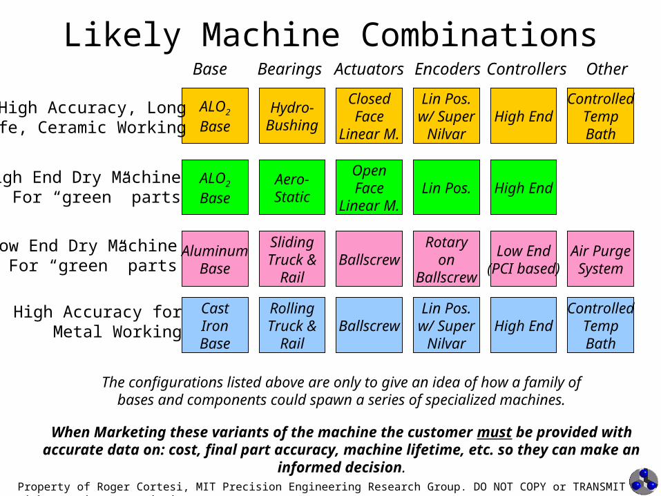
Likely Machine Combinations
ALO2
Base
CastIronBase
AluminumBase
Hydro-Bushing
Aero-Static
RollingTruck &
Rail
SlidingTruck &
Rail
ClosedFace
Linear M.
OpenFace
Linear M.
Ballscrew
Lin Pos.w/ SuperNilvar
Lin Pos.
Rotaryon
Ballscrew
High End
Low End(PCI based)
Base Bearings Actuators Encoders Controllers Other
ControlledTempBath
Air PurgeSystem
High Accuracy, LongLife, Ceramic Working
High End Dry MachineFor “green” parts
High EndALO2
Base
Low End Dry MachineFor “green” parts
High Accuracy forMetal Working Ballscrew
Lin Pos.w/ SuperNilvar
High EndControlled
TempBath
The configurations listed above are only to give an idea of how a family ofbases and components could spawn a series of specialized machines.
When Marketing these variants of the machine the customer must be provided with accurate data on: cost, final part accuracy, machine lifetime, etc. so they can make an informed decision.

Property of Roger Cortesi, MIT Precision Engineering Research Group. DO NOT COPY or TRANSMIT without written permission.
Machine Accuracy Map
1.2 micron envelope
0.8 micron envelope
Part of this marketing method involves giving the customer real performance data that is a function of which machine components they choose.

Property of Roger Cortesi, MIT Precision Engineering Research Group. DO NOT COPY or TRANSMIT without written permission.
Background Slides

Property of Roger Cortesi, MIT Precision Engineering Research Group. DO NOT COPY or TRANSMIT without written permission.
The Double L “Wet” Machine
Ballscrew
Ballnut and Drive Motor Assembly
Hydrobushing
Hydrobushing Rail

Property of Roger Cortesi, MIT Precision Engineering Research Group. DO NOT COPY or TRANSMIT without written permission.
Thermally Centered
A lum inum O x ide P a rt
P a rt C en te r L ine
T he s truc tu re is cons tra ineda long the cen te rline o f the pa rt
The part and base are kept at the same temperature by flooding both with coolant.
If the part and base are both Aluminum Oxide they will expand at the same rate.
If they are of different materials the difference in expansion causes a radial error.
0.00 0.50 1.00 1.50 2.00 2.50 3.00
Granite
Cast Iron
Base Granite
Cast Iron
Granite
Cast Iron
Granite
Cast Iron
22
11
0.5
0.5
0.25
0.25
Bas
e M
ater
ial
and
Tem
p T
ole
ran
ce (
C)
Radial Thermal Error (microns)
Radial thermal errors as function of increase in part and base temperature for granite or cast iron bases
An Aluminum Oxide Base has the same as the part, therefore no radial errors due to uniform heating and cooling

Property of Roger Cortesi, MIT Precision Engineering Research Group. DO NOT COPY or TRANSMIT without written permission.
Preliminary Work on a Dry Machine

Property of Roger Cortesi, MIT Precision Engineering Research Group. DO NOT COPY or TRANSMIT without written permission.
Axtrusion Based Concept
Con’s•Large Error Gains (Abbe Errors)•Potentially Very Heavy Structure
Pro’s•Simplest Structure•Excellent Access to Part and Spindles•Easy to Offer Multiple Configurations

Property of Roger Cortesi, MIT Precision Engineering Research Group. DO NOT COPY or TRANSMIT without written permission.
The Dry Machine and the AxtrusionThe Axtrusion is a linear motion concept developed and implemented by Prof. Slocum and Roger Cortesi.
It uses porous air bearings and linear motors to make an easy to assemble, non-contact linear motion system.
Linear M otorPermanent M agnets
Carriage
W ay
Top PrecisionSurface
Side PrecisionSurface
Because it is a non-contact air system it will should be very robust with respect to the ceramic swarf

Property of Roger Cortesi, MIT Precision Engineering Research Group. DO NOT COPY or TRANSMIT without written permission.
Axtrusion Components
Linear M otorPerm anent M agnets
Carriage
W ay
Top PrecisionSurface
Side PrecisionSurface
Linear M otor CoilTop OutboardPorous GraphiteAir Bearings
Top InboardPorous GraphiteAir Bearings
Side PorousGraphite AirBearings
Not Shown: Position Encoder and Position Encoder Scale

Property of Roger Cortesi, MIT Precision Engineering Research Group. DO NOT COPY or TRANSMIT without written permission.
How the Axtrusion™ Works
The attractive force between the motor coil and magnets preload the air bearings.
Changing the values of , ym, and zm the values for Fside, Ftop1, and Ftop2 can all be set independently
z
zm
y2
y1
ym
FmFside
Ftop1 Ftop2
B earingB earing
Bearing
Motor
Y Axis
Z Axis
Preload ResultsFside 504 NFtop1 393 NFtop2 641 N
Prototype ParametersTheta 26 degreesFm 2300 NY1 30 mmY2 260 mmYm 145 mmZ 81 mmZm 25 mm

Property of Roger Cortesi, MIT Precision Engineering Research Group. DO NOT COPY or TRANSMIT without written permission.
2nd Generation Sketch of Dry Machine
Dry Lathe
Contact PointX & Z Ax is COMYAxis COM
Rough Error Abbe Errors were calculated for this design with the following assumptions:
•Average errors in Prototype Axtrusion used for the work piece and grinder carriage’s pitch, yaw, and roll errors.
–No MAPPING CASE: Error magnitude is the actual error in prototype, 10 radians (2 arc sec)–PERFECT MAPPING CASE: Error magnitude is the repeatability of prototype 2.5 radians (0.5 arc sec)
•No errors in spindles•Rough machine size based on a 15” dia. by 12” long work piece•All Magnitude Abbe errors are added for a worst case
Maximum Total Abbe ErrorWith NO Error Mapping
•Radial 13 m (0.0005”)•Axial 10 m (0.0004”)
Maximum Total Abbe ErrorWith PEFECT Error Mapping
•Radial 3.2 m (0.00013”)•Axial 2.5 m (0.0001”)

Property of Roger Cortesi, MIT Precision Engineering Research Group. DO NOT COPY or TRANSMIT without written permission.
Notes on the Dry Machine Concept
The previous error estimates are for an Axtrusion with a permanent magnet linear motor. A coreless linear motor would dramatically reduces these error motions further.
Estimated Total Abbe ErrorWith NO Error Mapping
•Radial 9.8 m•Axial 7.4 m
Estimated Total Abbe ErrorWith PEFECT Error Mapping
•Radial 2.4 m•Axial 1.8 m
Total RMS Abbe ErrorWith NO Error Mapping
•Radial 6.6 m•Axial 5.0 m
Total RMS Abbe ErrorWith PEFECT Error Mapping
•Radial 1.6 m•Axial 1.2 m