Property of American Airlines Telescopic Hydraulic Cylinders · good safety practices may cause...
35
Property of American Airlines
Transcript of Property of American Airlines Telescopic Hydraulic Cylinders · good safety practices may cause...
Prope
rty o
f Am
erica
n Airli
nes
ceastin
Typewritten Text
Telescopic Hydraulic Cylinders
ceastin
Typewritten Text
ceastin
Typewritten Text
ceastin
Typewritten Text
ceastin
Typewritten Text
LIFT CYLINDER - (CUSTOM HOISTS, INC.) 5-2Page 1
TESCO EQUIPMENT LLC
Section 2: Lift Cylinder - (Custom Hoists, Inc.)
Single Acting Telescopic Hydraulic Cylinders
• Installation, Operation and Maintenance Manual
Nov. 05
Prope
rty o
f Am
erica
n Airli
nes

THIS PAGE INTENTIONALLY LEFT BLANK
Prope
rty o
f Am
erica
n Airli
nes
INSTALLATION, OPERATION
AND
MAINTENANCE MANUAL
FOR
400 MODEL SERIES
AND
4000 MODEL SERIES
SINGLE ACTING TELESCOPIC HYDRAULIC CYLINDERS
Pro
perty
of A
mer
ican
Airline
s

Prope
rty o
f Am
erica
n Airli
nes

- 1 -
Table of Contents
Table of Contents………………………………………………….. 1 General Information……………………………………………….. 2-3 Storage and Handling……………………………………………… 4 Hydraulic Oil Recommendations………………………………….. 5-6 Installation…………………………………………………………. 7 Operation…………………………………………………………… 8-9 Preventive Maintenance……………………………………………. 10 Head Nut Adjustment Procedures………………………………….. 11 Bleed Air from Cylinder 400 Series with Manual Bleeder for Serial Numbers 400,000 to 999,999…………………………. 12 Bleed Air from Cylinder 4000 Series Self Bleeding for Serial Numbers 1,000,000 and above…………………………. 13 Disassembly / Reassembly Instructions for Serial Numbers 400,000 to 999,999…………………………. 14-18 Disassembly / Reassembly Instructions for Serial Numbers Over 1,000,000………………………………. 19-23 Disassembly / Assembly Tools…………………………………….. 24-25 Ordering Information………………………………………………. 26-28 Warranty Information………………………………………………. 29
Prope
rty o
f Am
erica
n Airli
nes

- 2 -
General Information
This symbol is intended to alert the user to the presence of important installation, operation and maintenance instructions that follow. Failure to use good safety practices may cause severe injury or death and/or damage to the equipment. For your protection, carefully read and understand the information in this manual prior to installation, operation and/or maintenance to your Custom Hoists single acting telescopic cylinder.
• Return Policy Authorization from Custom Hoists, Inc. must be obtained prior to any product
being returned. Unauthorized returns will not be accepted. Freight covering return goods must be prepaid.
• Normal Service Items Packing, wipers and bushings are considered normal service or replacement
items. These items are subject to contamination from external and internal foreign materials, many of which are abrasive in nature, causing abnormal wear or damage to the parts, to the extent replacements are required.
• Individual Plunger Lifting Capacity
SPECIFIC OPERATING PRESSURES PLUNGER CROSS DIAMETER SECTIONAL 1,500 PSI 1,800 PSI 2,000 PSI 2,500 PSI (IN.) AREA (SQ. IN.) (LBS.) (LBS.) (LBS.) (LBS.) 2 3.14 4,710 5,672 6,280 7,850 3 7.06 10,590 12,708 14,120 17,650 4 12.56 18,840 22,608 25,120 31,400 5 19.63 29,445 35,334 39,260 49,075 6 28.27 42,405 50,886 56,540 70,675 7 38.48 57,720 69,264 76,960 CONSULT FACTORY 8 50.26 75,390 90,468 100,520 CONSULT FACTORY 8 1/4 53.50 80,250 96,300 107,000 CONSULT FACTORY 9 1/8 65.40 98,100 117,720 130,800 CONSULT FACTORY 9 3/4 74.50 111,750 134,100 149,000 CONSULT FACTORY
• Safety Warning
Prope
rty o
f Am
erica
n Airli
nes

- 3 -
General Information
• Fluid Capacity Factors
400 series cylinders 4000 series cylinders
To determine fluid displacement (in gallons) to fill a particular cylinder size, multiply desired cylinder stroke and “fill” factor from above chart. For fully extended displacement, multiply desired cylinder stroke and “extend” factor from above chart.
Example: Model No. 85-4002-250 Fill: .024 x 250 = 6.0 gal. Extend: .128 x 250 = 32.0 gal.
Cylinder Size Fill Extend
32 .017 .032 42 .018 .043 43 .013 .032 52 .019 .071 53 .017 .057 54 .013 .044 62 .023 .105 63 .020 .087 64 .019 .073 72 .027 .145 73 .024 .125 74 .023 .106 75 .020 .091 82 .030 .192 83 .028 .169 84 .026 .147 85 .024 .128 86 .021 .112
8 1/4 3 .029 .150 8 1/4 4 .030 .134 8 1/4 5 .028 .115 8 1/4 6 .021 .097
92 .040 .251 93 .029 .222 94 .031 .197 95 .030 .174 96 .026 .155
9 3/4 2 .053 .277 9 3/4 3 .036 .240 9 3/4 4 .038 .210 9 3/4 5 .036 .185 9 3/4 6 .032 .163
Cylinder Size Fill Extend
32 .023 .032 42 .032 .043 43 .015 .032 52 .043 .071 53 .025 .057 54 .015 .044 62 .063 .105 63 .036 .087 64 .025 .073 72 .088 .145 73 .050 .125 74 .035 .106 75 .025 .091 82 .111 .192 83 .068 .169 84 .046 .147 85 .033 .128 86 .025 .112
8 1/4 3 .061 .150 8 1/4 4 .049 .134 8 1/4 5 .037 .115 8 1/4 6 .024 .097
92 .153 .251 93 .073 .222 94 .059 .197 95 .046 .174 96 .033 .155
9 3/4 2 .159 .277 9 3/4 3 .079 .240 9 3/4 4 .065 .210 9 3/4 5 .052 .185 9 3/4 6 .039 .163
Prope
rty o
f Am
erica
n Airli
nes
- 4 -
Storage and Handling
• Storage Your Custom Hoists single acting telescopic cylinder should be stored
fully closed in a vertical position with the plunger end down. Be certain the cylinder is blocked securely to keep it upright. Storing with the plunger end down keeps oil on the seals which protects them from drying out. If horizontal storage cannot be avoided, the cylinder should be rotated into a new position every two months to prevent drying, distortion and deterioration of the seals.
Cylinders should be kept in an environment that is protected from excessive moisture and temperature extremes. Daytime heat bakes oil out of sealing materials which causes leaks and rapid wear when the cylinder is placed in service. Cooling at night causes water condensation and corrosion damage to wear surfaces. Widely varying temperatures and tightly closed ports may cause pressure to build up inside the cylinder to the point where the piston(s) moves far enough to expose the plunger to contamination and/or corrosion.
Storage areas that allow exposure to rain, snow and extreme cold must be avoided.
• Handling Whenever moving or handling your Custom Hoists single acting
telescopic cylinder, care should always be exercised to avoid any damage that may cause a detrimental effect to future performance.
It is always a good practice to lift your cylinder by using a nylon sling. DO NOT use a chain which can easily scar or scratch machined and polished surfaces and thereby lead to premature failure. Cylinder bodies and plungers can be easily dented with chain hoists.
Your cylinder should only be handled in the closed or collapsed position to avoid any damage to the machined and polished sealing surfaces. Never step or stand on the cylinder, especially the extended polished sealing areas.
Pin-eyes are for mounting the cylinder…….NOT LIFTING! Premature failure can be the result of lifting the cylinder by the pin-eye which will pull the plunger out of the cylinder body and allow foreign material to enter the cylinder and thereby contaminate the hydraulic system.
Prope
rty o
f Am
erica
n Airli
nes

- 5 -
Hydraulic Oil Recommendations
All internal cylinder parts are lubricated by hydraulic oil in the circuit. Particular attention must be paid to the condition and level of the oil in the circuit. Dirty oil is one of the main causes of hydraulic component failure resulting in expensive downtime. Dirty oil is detectable, a sample on a dipstick will show its condition. Take the sample and put a drop on a blotter cloth or paper, any revealed residue means dirty oil. To replace the oil supply, drain and flush the entire system and clean or replace any filter screens. Fill the system with new oil suitable and recommended for use in circuits involving Custom Hoists, Inc. cylinders with the following specifications:
***NOTICE*** These suggestions are intended as a guide only. When purchasing hydraulic oil, show these specifications to your oil supplier for final oil recommendations.
• Viscosity Recommendations: Approximately 100 SSU is considered optimum operating viscosity. 50 SSU Minimum @ Operating Temperature 7500 SSU Maximum @ Starting Temperature 150 to 225 SSU @ 100°F (37.8°C) (Generally) 44 to 48 SSU @ 210°F (98.9°) (Generally) • Approximate SSU at… 100°F 210° Oil Grade (37.8°C) (98.9°C) SAE 10 150 43 SAE 20 330 51
Prope
rty o
f Am
erica
n Airli
nes
- 6 -
Hydraulic Oil Recommendations
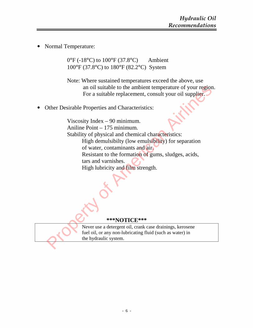
• Normal Temperature: 0°F (-18°C) to 100°F (37.8°C) Ambient 100°F (37.8°C) to 180°F (82.2°C) System Note: Where sustained temperatures exceed the above, use an oil suitable to the ambient temperature of your region. For a suitable replacement, consult your oil supplier. • Other Desirable Properties and Characteristics: Viscosity Index – 90 minimum. Aniline Point – 175 minimum. Stability of physical and chemical characteristics: High demulsibilty (low emulsibility) for separation of water, contaminants and air. Resistant to the formation of gums, sludges, acids, tars and varnishes. High lubricity and film strength.
***NOTICE*** Never use a detergent oil, crank case drainings, kerosene fuel oil, or any non-lubricating fluid (such as water) in the hydraulic system.
Prope
rty o
f Am
erica
n Airli
nes
- 7 -
Installation
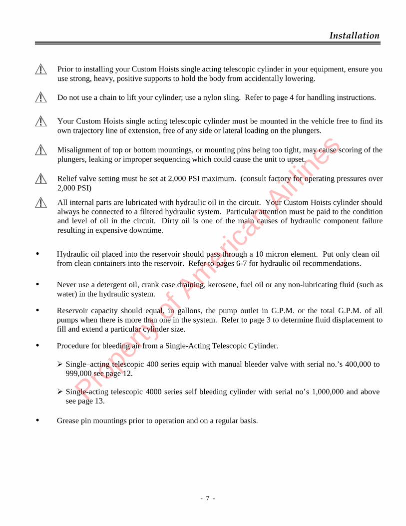
• Hydraulic oil placed into the reservoir should pass through a 10 micron element. Put only clean oil from clean containers into the reservoir. Refer to pages 6-7 for hydraulic oil recommendations.
• Never use a detergent oil, crank case draining, kerosene, fuel oil or any non-lubricating fluid (such as
water) in the hydraulic system.
• Reservoir capacity should equal, in gallons, the pump outlet in G.P.M. or the total G.P.M. of all pumps when there is more than one in the system. Refer to page 3 to determine fluid displacement to fill and extend a particular cylinder size.
• Procedure for bleeding air from a Single-Acting Telescopic Cylinder.
� Single–acting telescopic 400 series equip with manual bleeder valve with serial no.’s 400,000 to 999,000 see page 12.
� Single-acting telescopic 4000 series self bleeding cylinder with serial no’s 1,000,000 and above
see page 13. • Grease pin mountings prior to operation and on a regular basis.
Prior to installing your Custom Hoists single acting telescopic cylinder in your equipment, ensure you use strong, heavy, positive supports to hold the body from accidentally lowering.
Do not use a chain to lift your cylinder; use a nylon sling. Refer to page 4 for handling instructions.
Your Custom Hoists single acting telescopic cylinder must be mounted in the vehicle free to find its own trajectory line of extension, free of any side or lateral loading on the plungers.
Misalignment of top or bottom mountings, or mounting pins being too tight, may cause scoring of the plungers, leaking or improper sequencing which could cause the unit to upset.
Relief valve setting must be set at 2,000 PSI maximum. (consult factory for operating pressures over 2,000 PSI)
All internal parts are lubricated with hydraulic oil in the circuit. Your Custom Hoists cylinder should always be connected to a filtered hydraulic system. Particular attention must be paid to the condition and level of oil in the circuit. Dirty oil is one of the main causes of hydraulic component failure resulting in expensive downtime.
Prope
rty o
f Am
erica
n Airli
nes
- 8 -
Operation
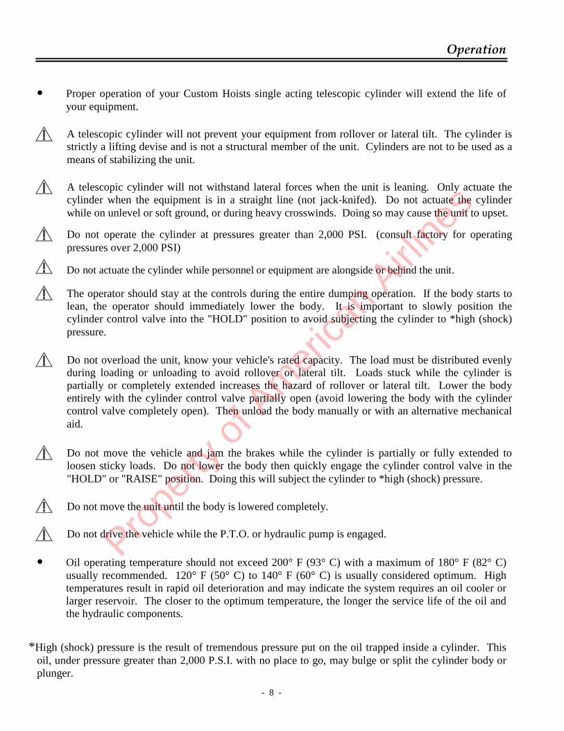
• Proper operation of your Custom Hoists single acting telescopic cylinder will extend the life of your equipment.
• Oil operating temperature should not exceed 200° F (93° C) with a maximum of 180° F (82° C) usually recommended. 120° F (50° C) to 140° F (60° C) is usually considered optimum. High temperatures result in rapid oil deterioration and may indicate the system requires an oil cooler or larger reservoir. The closer to the optimum temperature, the longer the service life of the oil and the hydraulic components.
*High (shock) pressure is the result of tremendous pressure put on the oil trapped inside a cylinder. This
oil, under pressure greater than 2,000 P.S.I. with no place to go, may bulge or split the cylinder body or plunger.
A telescopic cylinder will not prevent your equipment from rollover or lateral tilt. The cylinder is strictly a lifting devise and is not a structural member of the unit. Cylinders are not to be used as a means of stabilizing the unit.
A telescopic cylinder will not withstand lateral forces when the unit is leaning. Only actuate the cylinder when the equipment is in a straight line (not jack-knifed). Do not actuate the cylinder while on unlevel or soft ground, or during heavy crosswinds. Doing so may cause the unit to upset.
Do not operate the cylinder at pressures greater than 2,000 PSI. (consult factory for operating pressures over 2,000 PSI)
The operator should stay at the controls during the entire dumping operation. If the body starts to lean, the operator should immediately lower the body. It is important to slowly position the cylinder control valve into the "HOLD" position to avoid subjecting the cylinder to *high (shock) pressure.
Do not actuate the cylinder while personnel or equipment are alongside or behind the unit.
Do not overload the unit, know your vehicle's rated capacity. The load must be distributed evenly during loading or unloading to avoid rollover or lateral tilt. Loads stuck while the cylinder is partially or completely extended increases the hazard of rollover or lateral tilt. Lower the body entirely with the cylinder control valve partially open (avoid lowering the body with the cylinder control valve completely open). Then unload the body manually or with an alternative mechanical aid.
Do not move the vehicle and jam the brakes while the cylinder is partially or fully extended to loosen sticky loads. Do not lower the body then quickly engage the cylinder control valve in the "HOLD" or "RAISE" position. Doing this will subject the cylinder to *high (shock) pressure.
Do not move the unit until the body is lowered completely.
Do not drive the vehicle while the P.T.O. or hydraulic pump is engaged. Prope
rty o
f Am
erica
n Airli
nes

- 9 -
Operation
• Cylinder Operation:
To Extend a Single-Acting Telescopic Cylinder: High pressure oil from the pump is directed by the control valve through port (A) to fill
the cylinder. As the system pressure rises, the oil pushes on the bottom of the largest plunger (F)
forcing it to move out. The outside diameter or sealing area of the plunger (D) determines the effective area.
As the plunger extends, the oil trapped between the plunger walls (E) is released through
internal port holes in the plunger. When the largest stage is fully extended, the next largest will proceed to extend, etc.
400 series model equip with manual bleed valve with serial numbers 400,000 to 999,000. It will be necessary to bleed the trapped air from the cylinder. Any air in the hydraulic system will be trapped in the end of the cylinder (B) and may be bled off through the bleeder valve (C). It is advisable to bleed air from the cylinder weekly to free entrapped air. This will result in a smoother operation. Refer to page 12 for procedures to bleed air from a single acting telescopic cylinder. 4000 series models are self bleeding with serial numbers 1,000,000 and above. Air introduced to the cylinder during normal operation will be returned to the tank during its normal operation. If for some reason a large amount of air is introduced into the cylinder see page 13 for procedures to bleed air from a single acting cylinder. To Retract:
A single-acting telescopic cylinder must be retracted by gravity or mechanical means. • A damp to light film of oil on each plunger indicates a good cylinder operation. A small
accumulation of oil may be noticed on the plunger at the head nut after many cycles. This should not be mistaken for packing leakage.
400 series model equip with manual bleeder valve with serial no. 400,000 to 999,000
4000 series self bleeding model with serial no. 1,000,000 and above Pro
perty
of A
mer
ican
Airline
s

- 10 -
Preventive Maintenance
• Hydraulic oil should be checked daily, added to if needed and changed on a regular schedule along with filters and filter screens in accordance with the Manufacturer's recommendations.
• Hydraulic system should be flushed periodically. • Hydraulic oil poured into the reservoir should pass through a 10 micron
element. Pour only clean oil from clean containers into the reservoir. Refer to pages 5-6 for hydraulic oil recommendations.
• Bleed air from the cylinder weekly to free entrapped air. This will result in a
smoother operation. Refer to page 12 for procedures to bleed air from a single acting telescopic cylinder. (For 400 series, serial #400,000 to 999,000)
• Grease the cylinder base end and plunger end pin mountings regularly. • Fully extend cylinder and check plungers for proper sequencing, abnormal
wear and/or scoring on a regular basis. • Check head nut areas for hydraulic oil leaks on a regular basis. Refer to page
11 for procedures for adjusting head nuts on a single acting telescopic cylinder.
• Do not leave your cylinder partially or fully extended. Exposed plunger
surfaces are subject to rust.
Before making adjustments or repairs to the cylinder when mounted in the unit, use strong, heavy, positive supports to hold the body from accidentally lowering. Place the cylinder valve in the "LOWER" position to ensure the pressure is relieved in the cylinder.
Hydraulic hoses should be checked regularly and replaced if worn or damaged.
Prope
rty o
f Am
erica
n Airli
nes

- 11 -
Head Nut Adjustment Procedures
• For leaking cylinders:
1. Loosen set screw(s) in head nut of leaking stage(s). 2. Tap head nut lightly around circumference with a hammer. 3. Using a chain wrench, back head nut off one half to one full turn. If
plunger turns as you are turning the head nut, the plunger will have to be held, preferably with a strap wrench.
4. Cycle cylinder two or three times to reset vee ring packing. 5. Tighten head nut one half turn farther than it was loosened. 6. Tighten set screw(s).
• For mis-sequencing cylinders:
1. Loosen set screw in head nut on stage that is sticking. 2. Tap head nut lightly around circumference with a hammer. 3. Using a chain wrench, back off head nut one half turn. 4. Cycle cylinder. If cylinder still mis-stages, turn head nut another half
turn. 5. Cycle cylinder. If cylinder still mis-stages, tighten the head nut on the
next stage that is extending. If plunger turns as you are turning the head nut, the plunger will have to be held, preferably with a strap wrench.
6. Tighten set screw(s).
Before making adjustments or repairs to the cylinder when mounted in the unit, use strong, heavy, positive supports to hold the body from accidentally lowering. Place the cylinder valve in the "LOWER" position to ensure the pressure is relieved in the cylinder.
Prope
rty o
f Am
erica
n Airli
nes

- 12 -
Bleeding Air from the Cylinder 400 Series Cylinder Model with Serial Numbers 400,000 to 999,000
For Single-Acting Telescopic Cylinder Equip with Manual Bleeder Valve:
1. Empty the dump body of any material. 2. Remove the cover plate from the doghouse of the dump body to access the
cylinder bleeder valve.
3. Fully extend the cylinder, raising the empty dump bed.
4. Lower the dump bed to within one foot from the frame.
5. Turn the bleeder valve in a counterclockwise direction. This opens the valve and allows the air to escape from the cylinder.
6. When a steady stream of oil comes from the bleeder, turn the valve in a
clockwise direction until it is closed. Notes:
• For consistent operation of telescopic cylinders, it is advisable to bleed the air from the cylinder weekly.
• Older systems may be susceptible to air induced; make certain that there is
no part of the system that can allow air to be drawn into the system. • Avoid hose routing that will cause air to be trapped. Large loops in the hose
routing will be areas for air to collect. • It may be more difficult to bleed if reservoir is far from the cylinder and
positioned very low on respect to the cylinder.
• Always allow adequate air space in hydraulic reservoirs per system recommendations.
• Upon initial installation it may be necessary to allow time for the air to
dissipate from the oil in the reservoir.
• Check oil level periodically to avoid reservoir being drained during operation.
If these procedures fail to correct the problem, contact the factory or an authorized service center for further instructions
Prope
rty o
f Am
erica
n Airli
nes

- 13 -
Bleeding Air from the Cylinder for 4000 Series Cylinder Model with Serial Numbers 1,000,000 and above
For Single–Acting Telescopic Self Bleeding 4000 Series Cylinders:
1. If air pressure is being used to aid in the installation such to raise mounting to attachment position, it is advised to remove air pressure before cycling cylinder.
2. After installation, cycle the cylinder approximately 5 times to remove air. 3. While typically 5 cycles is usually sufficient; it may take several more cycles to
bleed out enough air to eliminate erratic operation. Not all systems are the same and considerable more cycles may be needed upon installation
4. Cylinder will continue to bleed itself during use.
Notes:
• Older systems may be susceptible to air induced; make certain that there is no part of the system that can allow air to be drawn into the system.
• Avoid hose routing that will cause air to be trapped. Large loops in the hose
routing will be areas for air to collect.
• It may be more difficult to bleed if reservoir is far from the cylinder and positioned very low on respect to the cylinder.
• Always allow adequate air space in hydraulic reservoirs per system
recommendations.
• Upon initial installation it may be necessary to allow time for the air to dissipate from the oil in the reservoir.
• Check oil level periodically to avoid reservoir being drained during operation.
If these procedures fail to correct the problem, contact the factory or an authorized service center for further instructions.
Prope
rty o
f Am
erica
n Airli
nes

- 14 -
Disassembly / Reassembly Instructions for 400 Series Cylinder Model with Serial Numbers 400,000 to 999,000
• We recommend field service repairs be limited to replacement of packing,
bushings, wipers and adjustment of head nuts for leakage and proper sequencing. • Before servicing the unit, check the plungers for damage. If the plunger is scored
or scratched, smooth out marks with a fine stone or emery cloth to avoid damage to the new seals.
• After repair, a damp to light film of oil may be apparent on the plunger. A small
accumulation of oil may be noticed on the plunger at the adjustable head nut after many cycles. This should not be mistaken for packing leakage.
• If a cylinder cannot be corrected by minor field repair, we recommend that the
cylinder be returned to Custom Hoists, or a factory qualified service dealer. • If necessary to disassemble a cylinder due to a damaged part such as a plunger, the
cylinder should be completely disassembled and all parts inspected. When requesting information or ordering parts, refer to the cylinder and serial numbers located at the base end of the cylinder as described in the ordering section of this booklet. A Major Repair Kit should be installed when rebuilding the cylinder.
• Refer to pages 24 & 25 for tools commonly used for assembly and disassembly of
Custom Hoists single acting telescopic cylinders.
Before making adjustments or repairs to the cylinder when mounted in the unit, use strong, heavy, positive supports to hold the body from accidentally lowering. Place the cylinder valve in the "LOWER" position to ensure the pressure is relieved in the cylinder.
Prope
rty o
f Am
erica
n Airli
nes

- 15 -
Disassembly / Reassembly Instructions for 400 Series Cylinder Model with Serial Numbers 400,000 to 999,000
• The following illustrations will serve as guide lines for the purpose of servicing a
400 model single acting telescopic cylinder, and is intended to clearly show the essential steps to be taken for the complete disassembly.
• Step 1 - Parts Identification Figure 1 The cylinder is best serviced mounted in the vertical
position, for both disassembly and assembly. Also, it is best located where a hoist can be used directly overhead of the cylinder for removing the plungers if complete disassembly is required. A typical stand is shown in figure 1, made of angle welded to a base anchored to the floor and an adjustable wraparound chain to secure the cylinder to the stand. Because of oil spillage and safety, we recommend draining the cylinder of oil before disassembling. Lay the cylinder horizontally with the port down and open. Rotate the last plunger so the bleeder hole is on top and open.
*Packing Set
**Plunger Stop fits inside I.D. of Retaining Ring
Plunger Stop
Remember - use proper safety equipment.
Figure 2 shows a typical sequence of disassembling the cylinder plungers in steps which are further described in this manual.
Retaining Ring
Step 2 Set Screw (Nylon Slug)
Step 3 Head Nut
Step 4 Top Bushing
Step 6 **Retaining Ring
**Plunger Stop
Guide Ring
*Step 5 Packing Set, Wave Spring & Lower Bushing
Wave Spring (ends down) Lower Bushing (step down)
Figure 2
Prope
rty o
f Am
erica
n Airli
nes

- 16 -
Disassembly / Reassembly Instructions for 400 Series Cylinder Model with Serial Numbers 400,000 to 999,000
• Step 2 - Set Screws (Figure 3) All head nuts are secured to the plunger by a
set screw. Under the set screw is a nylon slug to protect the plunger threads. To remove the head nut, the set screw must be loosened using an allen wrench. (Figure 12)
• Step 3 - Head Nuts (Figure 4)
After the set screws have been loosened, tap head nut gently around its circumference and unscrew the head nut with a chain wrench, or an equivalent tool. Do not use a chisel, punch or weld any studs to the head nut to remove. (Figure 13)
• Step 4 - Bushings (Figure 5) Using a bushing removal tool (Figure 14),
Thread the ends into holes on top of bushings and lift the bushing upward.
• Step 5 - Packing, Wave Spring, Lower Bushing
(Figure 6)
To remove packing, wave spring and lower bushing, pull the plunger up about one foot. Add tape (Figure 15) to a clean area as shown in Figure 6. Push the plunger down past the parts then pull the plunger up. The internal parts will stick to the tape and be pulled out of the plunger. Repeat as needed.
Figure 3
Figure 4
Figure 5
Figure 6
Tape
Prope
rty o
f Am
erica
n Airli
nes

- 17 -
Disassembly / Reassembly Instructions for 400 Series Cylinder Model with Serial Numbers 400,000 to 999,000
• Step 6 - Retainer Rings (Figure 7) The retaining ring has a small hole at each
end. Insert a pointed screwdriver to move the hole out into the I.D. Place a steel shim behind the retainer. Using the Custom Hoists' retainer ring tool (Figure 16) insert the points into the retainer and close the retainer against the tube. Pull the tube to remove the retainer and plunger stop.
• Reassembly of Cylinder All bores in the packing area and plunger outside diameters must be free of tool
marks and scratches. Polish with a fine paper, crocus cloth or a Scotch Brite pad. All parts should be clean and free of any contamination. A complete major repair kit, as listed on page 27 (ordering information) is recommended. Drop all plungers into the body in the vertical position, as shown in Fig. 1. Assemble the remaining parts in the reverse sequence as listed in Fig. 2. The packing should be presoaked in oil before installing (do not use a detergent oil). Note, see Fig. 2 for the direction of the packing. Using a tool similar to Fig. 17, seat each lip individually, making sure packing is nestled uniformly. After the head nuts are adjusted, (see Step 7, Fig. 8 on page 23) make sure there is a nylon slug under the set screw before securing the head nut to the plunger. After installing the cylinder in the unit, open the bleeder screw and extend the cylinder to bleed the air. More than one extension may be needed to assure all the air is removed and cylinder operates smoothly. Refer to page 12 for procedures to bleed air from a single acting telescopic cylinder
Figure 7
Prope
rty o
f Am
erica
n Airli
nes

- 18 -
Disassembly / Reassembly Instructions for 400 Series Cylinder Model with Serial Numbers 400,000 to 999,000
Figure 13 Chain wrench for
removing Head Nuts
Figure 12 Allen wrench for
removing set screws
Figure 14 Threaded tool for
removing bushings
Figure 15 Adhesive tape for
removing packing set and bottom bushing
Figure 16 Retaining Ring Removal Tool
Figure 17 Installation of packing set
Prope
rty o
f Am
erica
n Airli
nes
- 19 -
Disassembly / Reassembly Instructions for 4000 Series Cylinder Model with Serial Numbers 1,000,000 and above
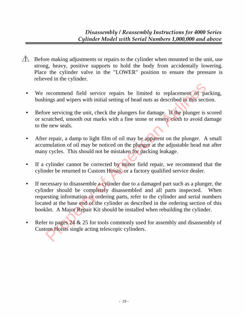
• We recommend field service repairs be limited to replacement of packing,
bushings and wipers with initial setting of head nuts as described in this section. • Before servicing the unit, check the plungers for damage. If the plunger is scored
or scratched, smooth out marks with a fine stone or emery cloth to avoid damage to the new seals.
• After repair, a damp to light film of oil may be apparent on the plunger. A small
accumulation of oil may be noticed on the plunger at the adjustable head nut after many cycles. This should not be mistaken for packing leakage.
• If a cylinder cannot be corrected by minor field repair, we recommend that the
cylinder be returned to Custom Hoists, or a factory qualified service dealer. • If necessary to disassemble a cylinder due to a damaged part such as a plunger, the
cylinder should be completely disassembled and all parts inspected. When requesting information or ordering parts, refer to the cylinder and serial numbers located at the base end of the cylinder as described in the ordering section of this booklet. A Major Repair Kit should be installed when rebuilding the cylinder.
• Refer to pages 24 & 25 for tools commonly used for assembly and disassembly of
Custom Hoists single acting telescopic cylinders.
Before making adjustments or repairs to the cylinder when mounted in the unit, use strong, heavy, positive supports to hold the body from accidentally lowering. Place the cylinder valve in the "LOWER" position to ensure the pressure is relieved in the cylinder.
Prope
rty o
f Am
erica
n Airli
nes

- 20 -
Disassembly / Reassembly Instructions for 4000 Series Cylinder Model with Serial Numbers 1,000,000 and above
• The following illustrations will serve as guide lines for the purpose of servicing a
4000 model single acting telescopic cylinder, and is intended to clearly show the essential steps to be taken for the complete disassembly.
• Step 1 - Parts Identification Figure 1 The cylinder is best serviced mounted in the vertical
position, for both disassembly and assembly. Also, it is best located where a hoist can be used directly overhead of the cylinder for removing the plungers if complete disassembly is required. A typical stand is shown in figure 1, made of angle welded to a base anchored to the floor and an adjustable wraparound chain to secure the cylinder to the stand. Because of oil spillage and safety, we recommend draining the cylinder of oil before disassembling. Lay the cylinder horizontally with the port down and open.
Figure 2
Remember - use proper safety equipment.
Figure 2 shows a typical sequence of disassembling the cylinder plungers in steps which are further described in this manual.
*Packing Set
**Retaining Ring
Bevel must face down
Step 2 Set Screw (Nylon Slug)
Step 3 Head Nut
Step 4 Bushing
*Step 5 Packing Set, Wave Spring & Lower Bushing Step 6
**Retaining Ring
Guide Ring
Wave Spring (ends down) Lower Bushing Pro
perty
of A
mer
ican
Airline
s

- 21 -
Disassembly / Reassembly Instructions for 4000 Series Cylinder Model with Serial Numbers 1,000,000 and above
• Step 2 - Set Screws (Figure 3) All head nuts are secured to the plunger by a
set screw. Under the set screw is a nylon slug to protect the plunger threads. To remove the head nut, the set screw must be loosened using an allen wrench. (Figure 12)
• Step 3 - Head Nuts (Figure 4) After the set screws have been loosened, tap
head nut gently around its circumference and unscrew the head nut with a chain wrench, or an equivalent tool. Do not use a chisel, punch or weld any studs to the head nut to remove. (Figure 13)
• Step 4 - Bushings (Figure 5) Using a bushing removal tool (Figure 14),
Thread the ends into holes on top of bushings and lift the bushing upward.
• Step 5 - Packing, Wave Spring, Lower Bushing (Figure 6)
To remove packing, wave spring and lower bushing, pull the plunger up about one foot. Add tape (Figure 15) to a clean area as shown in Figure 6. Push the plunger down past the parts then pull the plunger up. The internal parts will stick to the tape and be pulled out of the plunger. Repeat as needed.
Figure 3
Figure 4
Figure 5
Tape
Figure 6 Prope
rty o
f Am
erica
n Airli
nes

- 22 -
Disassembly / Reassembly Instructions for 4000 Series Cylinder Model with Serial Numbers 1,000,000 and above
• Step 6 - Retainer Ring (Figure 7) The retaining ring has a small hole at each
end. Insert a pointed screwdriver to move the hole out into the I.D. Place a steel shim behind the retainer. Using the Custom Hoists' retainer ring tool (Figure 16) insert the points into the retainer and close the retainer against the tube. Pull the tube to remove the retainer and plunger stop.
• Reassembly of Cylinder All bores in the packing area and plunger outside diameters must be free of tool
marks and scratches. Polish with a fine paper, crocus cloth or a Scotch Brite pad. All parts should be clean and free of any contamination. A complete major repair kit, as listed on page 27 (ordering information) is recommended. Drop all plungers into the body in the vertical position, as shown in Fig. 1. Assemble the remaining parts in the reverse sequence as listed in Fig. 2. The packing should be presoaked in oil before installing (do not use a detergent oil). Note, Fig. 2 for the direction of the packing. Using a tool similar to Fig. 17, seat each lip individually, making sure packing is nestled uniformly. After setting the head nuts (Step 7, Fig. 8), make sure there is a nylon slug under the set screw before securing the head nut to the plunger.
Figure 7
Prope
rty o
f Am
erica
n Airli
nes
- 23 -
Disassembly / Reassembly Instructions for 4000 Series Cylinder Model with Serial Numbers 1,000,000 and above
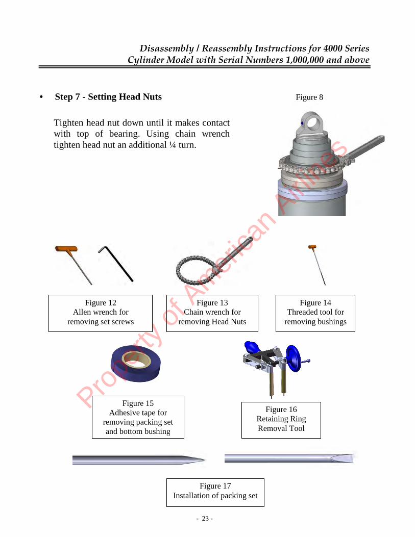
• Step 7 - Setting Head Nuts Figure 8
Tighten head nut down until it makes contact with top of bearing. Using chain wrench tighten head nut an additional ¼ turn.
Figure 13 Chain wrench for
removing Head Nuts
Figure 12 Allen wrench for
removing set screws
Figure 14 Threaded tool for
removing bushings
Figure 15 Adhesive tape for
removing packing set and bottom bushing
Figure 16 Retaining Ring Removal Tool
Figure 17 Installation of packing set
Prope
rty o
f Am
erica
n Airli
nes

- 24 -
Disassembly / Assembly Tools
• Tool Kit (Part No: 1-TL-16)
Used to install packing. • Chain Wrench with Add'l Chain (Part No: 1-CW-19)
Used to tighten and remove head nuts. • Strap Wrench (Part No: 1-TL-19)
To hold plungers from turning during assembly or disassembly.
• Thread Lift Rings - For lifting tubes
3" Tubes……..(Part No: 2-TL-20-3) 4" Tubes……..(Part No: 2-TL-20-4) 5" Tubes……..(Part No: 2-TL-20-5) 6" Tubes……..(Part No: 2-TL-20-6) 7" Tubes……..(Part No: 2-TL-20-7) 8" Tubes……..(Part No: 2-TL-20-8) 8 1/4" Tubes…(Part No: 2-TL-20-8 1/4) 9 1/8" Tubes…(Part No: 2-TL-20-9 1/8-1) (8 15/16" Thd.) 9 1/8" Tubes…(Part No: 2-TL-20-9 1/8) (9 1/16" Thd.) 9 3/4" Tubes…(Part No: 2-TL-20-9 3/4)
Prope
rty o
f Am
erica
n Airli
nes

- 25 -
Disassembly / Assembly Tools
• Pushers - For Installing Plunger Stops, Spacers and New Style Retainers 3" Tubes……..(Part No: 2-TL-21-3) 4" Tubes……..(Part No: 2-TL-21-4) 5" Tubes……..(Part No: 2-TL-21-5) 6" Tubes……..(Part No: 2-TL-21-6) 7" Tubes……..(Part No: 2-TL-21-7) 8" Tubes……..(Part No: 2-TL-21-8) 8 1/4" Tubes…(Part No: 2-TL-21-8 1/4) 9 1/8" Tubes…(Part No: 2-TL-21-9 1/8) 9 3/4" Tubes…(Part No: 2-TL-21-9 3/4) • Retainer Ring Tool / sn #400,000 and up (Part No: 2-TL-18) Used to remove retainer ring
(Pat. Pending #09/005,880) Pro
perty
of A
mer
ican
Airline
s

- 26 -
Ordering Information
• Model Number Identification
Example of model no.:
• Custom Hoists, Inc. model numbers and serial numbers are stamped on an
identification tag and welded on the O.D. of the cylinder body. Using these model numbers will eliminate misunderstandings when placing orders or requesting information.
Model number and serial number
identification tag
85-4002-250 *
CYLINDER TYPE (PREFIX*) NUMBER
LARGEST MOVING STAGE
NUMBER OF MOVING STAGES
*VARIOUS LETTERS USED TO IDENTIFY SPECIAL MANUFACTURED CYLINDERS
STROKE IN INCHES
DESIGN SEQUENCE NUMBER
Prope
rty o
f Am
erica
n Airli
nes

- 27 -
Ordering Information
Two types of repair kits are available for all Single-Acting Telescopic Cylinders. To order, use the cylinder prefix (*) number.
a) Kits to be used on 400 series single-acting telescopic cylinders with a serial numbers 400,000 up to 999,000.
Consists of the Following Kit Number Description Items for Each Stage When Used SK-(*)-400 Seal Kit Wiper Ring, Wave Spring Minor field repair Packing Set, Set Screw And Nylon Slug MPK -(*)-400 Minor Packing Kit Upper Bushing When bushings show Lower Bushing excessive wear Plus all items listed
for seal kit MRK -(*)-400 Major Repair Kit Plunger Stop, Wear Ring Major overhaul of And Retainer Ring cylinder Plus all items listed for seal
kit and minor packing kit
b) Kits to be used on 4000 series single-acting telescopic cylinders with a serial number of 1,000,000 or higher:
Consists of the Following Kit Number Description Items For Each Stage When Used SK-(*)-4000 Seal Kit Wiper Ring, Wave Spring Minor field repair Packing Set, Set Screw And Nylon Slug MPK -(*)-4000 Minor Packing Kit Upper Bushing When bushings Lower Bushing show excessive Plus all items listed wear for seal kit MRK -(*)-4000 Major Repair Kit Wear Ring And Major overhaul of Retainer Ring cylinder Plus all items listed for seal
kit and minor packing kit
Prope
rty o
f Am
erica
n Airli
nes

- 28 -
Ordering Information
• 400 Model Single-Acting Telescopic Cylinders standard design with serial
numbers 400,000 to 999,000.
• 4000 Model Single-Acting Telescopic Cylinders standard design with serial
numbers of 1,000,000 or higher. WEAR RING
RETAINER RINGS
VEE-PACKING
HEAD NUT
SET SCREW & NYLON SLUG
WIPER RING
UPPER BUSHING WAVE SPRING
LOWER BUSHING
WEAR RING RETAINER RINGS
VEE-PACKING
HEAD NUT
SET SCREW & NYLON SLUG
WIPER RING
UPPER BUSHING WAVE SPRING
PLUNGER STOP
LOWER BUSHING
Prope
rty o
f Am
erica
n Airli
nes
- 29 -
Warranty Information
LIMITED WARRANTY
Custom Hoists, Inc. warrants only products of its manufacture against operational failure caused by defective materials or workmanship which occur during proper and normal use within 24 months from the date of purchase from Custom Hoists, Inc. Custom Hoists, Inc.’s only obligation is to repair or replace, at its election, free of charge, any part of the product that its inspection shows to be defective and, if appropriate, the lowest round trip transportation charges from Custom Hoists’ original customer to Hayesville, Ohio and return, but excluding all transportation costs from Custom Hoists’ customer to its customer and all other costs such as removal and installation expenses. Written permission and direction for any warranty claim return must be first obtained from authorized Custom Hoists’ personnel. All returns must be accompanied with a complete written explanation of claimed defects and the circumstances of operational failure.
THIS WARRANTY IS IN LIEU OF ALL OTHER WARRANTIES OF ANY NATURE, EXPRESS OR IMPLIED, INCLUDING, BUT NOT LIMITED TO, WARRANTIES FOR MERCHANTABILITY OR FITNESS OR FOR ANY MEASURE OF SERVICE OR SUITABILITY OR FOR A SPECIFIC PURPOSE NOT WITHSTANDING ANY DISCLOSURE TO CUSTOM HOISTS OF THE USE TO WHICH THE PRODUCT IS TO BE PUT. THIS EXPRESS WARRANTY IS THE SOLE WARRANTY OF CUSTOM HOISTS, INC. THERE ARE NO WARRANTIES WHICH EXTEND BEYOND THE WARRANTY HEREIN EXPRESSLY SET FORTH. CUSTOM HOISTS, INC. SHALL NOT BE LIABLE FOR LOSS OF TIME, MANUFACTURING COSTS, LABOR, MATERIAL, LOSS OF PROFITS, INCIDENTAL OR CONSEQUENTIAL DAMAGES, DIRECT OR INDIRECT, BECAUSE OF DEFECTIVE PRODUCTS, WHETHER DUE TO RIGHTS ARISING UNDER THE CONTRACT OF SALE OR INDEPENDENTLY THEREOF, AND WHETHER OR NOT SUCH CLAIM IS BASED ON CONTRACT, TORT OR WARRANTY. THE SALE OF PRODUCTS OF CUSTOM HOISTS, INC., UNDER ANY OTHER WARRANTY OR GUARANTEE, EXPRESSED OR IMPLIED, IS NOT AUTHORIZED AND THERE ARE NO WARRANTIES MADE TO GOODS OR PRODUCTS MANUFACTURED BY ANYONE OTHER THAN CUSTOM HOISTS, INC.
Prope
rty o
f Am
erica
n Airli
nes

DIVISION OF STANDEX PRECISION ENGINEERING 771 RT. 30A WEST, P.O. BOX 98
HAYESVILLE, OHIO 44838 U.S.A. PH (419) 368-4721 FAX (419) 368-4209
Revision date: 04-2012 Printed in U.S.A.
Prope
rty o
f Am
erica
n Airli
nes