property damage! Retain instructions for future …Printed in U.S.A. 08090 0306/042/VCPVP...
44
Printed in U.S.A. 08090 0306/042/VCPVP 36005.00-0812 Dayton 7 x 12” Metal Cutting Band Saw Operating Instructions & Parts Manual 21C004 Please read and save these instructions. Read carefully before attempting to assemble, install, operate or maintain the product described. Protect yourself and others by observing all safety information. Failure to comply with instructions could result in personal injury and/or property damage! Retain instructions for future reference. Form 5S5525 ® Description Dayton 7 x 12” Horizontal Metal Cutting Band Saw provides speed with quality of cut for fabrication shops, machine shops, maintenance departments and contrac- tors. Blade speed ranges from 135 to 395 FPM to cut a variety of material ranging from cast iron, tool steel, bronze, aluminum and plastic. The feed rate is regulated by a hydraulic cylinder. The dial control for the cylinder is accessible during all stages of proper operation and can be set at any feed rate within its range. The wet cut operation provides a quality cut and extends blade life. Features include automatic shutoff, industrial rated speed reducer, heavy gauge steel construction, cast iron wheels, pulleys, head and bed. Additional features include swivel vise jaws for angle cuts, built in chip tray and wheel assemblies. Saw is controlled by magnetic switch. Specifications Capacity . . . . . . . . . . . . . . . . . 7” Rounds 4” Rounds at 45° 7 x 11 3 / 4” Rectangle at 90° 4 x 7” Rectangle at 45° Motor . . . . . . . . . . . . . . 1 HP, 1725 RPM, 110 Volts, 9.6 Amps, 60 Hz Blade speeds 135, 160, 225 and 395 FPM Blade size . . . . . . . . . . . . 3/4 x .035 x 93” Blade wheels . . . . . . . . . 11 1 / 2” Diameter, cast iron Overall dimensions . . . . 49 1 / 2 x 21 1 / 2 x 39” Crate dimensions . . . . 49.6 x 18.1 x 42.5” Weight . . . . . . . . . . . . . . . . . . . . . 322 lbs Shipping weight . . . . . . . . . . . . . . 389 lbs Coolant pump . . . . . . . . . . . . 2.6 Gallons per minute Coolant reservoir capacity . . 2.25 Gallons General Safety Information For your own safety, read all of the instructions and precautions before operating tool. Some dust created by power sanding, sawing, grinding, drilling and other con- struction activities contains chemicals known to cause cancer, birth defects or other reproductive harm. Some examples of these chemicals are: 1. Lead from lead-based paints. 2. Crystalline silica from bricks and cement and other masonry products. 3. Arsenic and chromium from chemically-treated lumber. Your risk from these exposures vary, depending on how often you do this type of work. To reduce your exposure to these chemicals: work in a well venti- lated area and work with approved safety equipment. Always wear OSHA/NIOSH approved, properly fitting face mask or respirator when using such tools. Unpacking Refer to Figure 1. Check for shipping damage. If damage has occurred, a claim must be filed with carrier immediately. Check for com- pleteness. Immediately report missing parts to dealer. The band saw comes completely assem- bled as one unit. Additional parts which need to be fastened to the saw should be located and accounted for before assembling: A Cylinder Assembly B Cylinder Support Rod with hex nut C 5 / 16-18 x 1” Hex Head Bolt D Axle (2) E Wheel (4) F Cotter Pin (8) G Work Stop with set screw H Work Stop rod with hex nut and two lock washers I Filter J Return Hose Be careful not to touch overhead power lines, piping, lighting, etc. if lift- ing equipment is used. Band Saw weighs approximately 322 lbs. proper tools, equipment and qualified personnel should be employed in all phases of unpacking and installation. IMPORTANT: Bed is coated with a pro- tectant. To ensure proper fit and opera- tion, remove coating. Coating is easily removed with mild solvents, such as mineral spirits, and a soft cloth. Avoid getting cleaning solution on paint or any of the rubber or plastic parts. Solvents may deteriorate these finishes. Use soap and water on paint, plastic or rubber components. After cleaning, cover all exposed surfaces with a light coating of oil. Never use highly volatile solvents. Non-flammable solvents are recom- mended to avoid possible fire hazard. E N G L I S H E S P A Ñ O L Figure 1 - Unpacking A C E D F I J H B G
Transcript of property damage! Retain instructions for future …Printed in U.S.A. 08090 0306/042/VCPVP...
Printed in U.S.A.080900306/042/VCPVP
36005.00-0812
Dayton 7 x 12” MetalCutting Band Saw
Operating Instructions & Parts Manual 21C004
Please read and save these instructions. Read carefully before attempting to assemble, install, operate or maintain the product described.Protect yourself and others by observing all safety information. Failure to comply with instructions could result in personal injury and/or property damage! Retain instructions for future reference.
Form 5S5525
®
DescriptionDayton 7 x 12” Horizontal Metal Cutting Band Saw provides speed with quality ofcut for fabrication shops, machine shops, maintenance departments and contrac-tors. Blade speed ranges from 135 to 395 FPM to cut a variety of material rangingfrom cast iron, tool steel, bronze, aluminum and plastic.
The feed rate is regulated by a hydraulic cylinder. The dial control for the cylinderis accessible during all stages of proper operation and can be set at any feed ratewithin its range. The wet cut operation provides a quality cut and extends bladelife. Features include automatic shutoff, industrial rated speed reducer, heavygauge steel construction, cast iron wheels, pulleys, head and bed.
Additional features include swivel vise jaws for angle cuts, built in chip tray andwheel assemblies. Saw is controlled by magnetic switch.
SpecificationsCapacity . . . . . . . . . . . . . . . . . 7” Rounds
4” Rounds at 45°7 x 113⁄4” Rectangle at 90°
4 x 7” Rectangle at 45°
Motor . . . . . . . . . . . . . . 1 HP, 1725 RPM,110 Volts, 9.6 Amps, 60 Hz
Blade speeds 135, 160, 225 and 395 FPM
Blade size . . . . . . . . . . . . 3/4 x .035 x 93”
Blade wheels . . . . . . . . . 111/2” Diameter,cast iron
Overall dimensions . . . . 491/2 x 211/2 x 39”
Crate dimensions . . . . 49.6 x 18.1 x 42.5”
Weight . . . . . . . . . . . . . . . . . . . . . 322 lbs
Shipping weight . . . . . . . . . . . . . . 389 lbs
Coolant pump . . . . . . . . . . . . 2.6 Gallonsper minute
Coolant reservoir capacity. . 2.25 Gallons
General Safety InformationFor your own safety,read all of the
instructions and precautions beforeoperating tool.
Some dust createdby power sanding,
sawing, grinding, drilling and other con -struction activities contains chemicalsknown to cause cancer, birth defects or other reproductive harm.
Some examples of these chemicals are:
1. Lead from lead-based paints.
2. Crystalline silica from bricks andcement and other masonry products.
3. Arsenic and chromium from chemically-treated lumber.
Your risk from these exposures vary,depending on how often you do thistype of work. To reduce your exposureto these chemicals: work in a well venti-lated area and work with approvedsafety equipment. Always wearOSHA/NIOSH approved, properly fittingface mask or respirator when using suchtools.
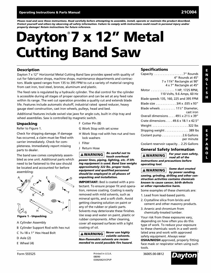
UnpackingRefer to Figure 1.
Check for shipping damage. If damagehas occurred, a claim must be filed withcarrier immediately. Check for com-pleteness. Immediately report missingparts to dealer.
The band saw comes completely assem-bled as one unit. Additional parts whichneed to be fastened to the saw shouldbe located and accounted for beforeassembling:
A Cylinder Assembly
B Cylinder Support Rod with hex nut
C 5⁄16-18 x 1” Hex Head Bolt
D Axle (2)
E Wheel (4)
F Cotter Pin (8)
G Work Stop with set screw
H Work Stop rod with hex nut and twolock washers
I Filter
J Return Hose
Be careful not totouch overhead
power lines, piping, lighting, etc. if lift-ing equipment is used. Band Saw weighsapproximately 322 lbs. proper tools,equipment and qualified personnelshould be employed in all phases ofunpacking and installation.
IMPORTANT: Bed is coated with a pro-tectant. To ensure proper fit and opera-tion, remove coating. Coating is easilyremoved with mild solvents, such asmineral spirits, and a soft cloth. Avoidgetting cleaning solution on paint orany of the rubber or plastic parts.Solvents may deteriorate these finishes.Use soap and water on paint, plastic orrubber components. After cleaning,cover all exposed surfaces with a lightcoating of oil.
Never use highlyvolatile solvents.
Non-flammable solvents are recom-mended to avoid possible fire hazard.
ENGLISH
ESPAÑOL
Figure 1 - Unpacking
A
C
E D
F
I
JH
B
G

General Safety Information(Continued)
Always follow properoperating procedures
as defined in this manual — even if youare familiar with use of this or similartools. Remember that being careless foreven a fraction of a second can result insevere personal injury.
BE PREPARED FOR JOB
1. Wear proper apparel. Do not wearloose clothing, gloves, neckties, rings,bracelets or other jewelry which mayget caught in moving parts ofmachine.
2. Wear protective hair covering to contain long hair.
3. Wear safety shoes with non-slip soles.
4. Wear safety glasses complying withUnited States ANSI Z87.1. Everydayglasses have only impact resistantlenses. They are NOT safety glasses.
5. Wear face mask or dust mask if oper-ation is dusty.
6. Be alert and think clearly. Never oper-ate power tools when tired, intoxicat-ed or when taking medications thatcause drowsiness.
PREPARE WORK AREA FOR JOB
1. Keep work area clean. Clutteredwork areas invite accidents.
2. Do not use power tools in dangerousenvironments. Do not use powertools in damp or wet locations. Donot expose power tools to rain.
3. Work area should be properly lighted.
4. Proper electrical receptacle should beavailable for tool. Plug 120 volt, sin-gle-phase plug directly into properlygrounded, three-prong receptacle.
5. Extension cords should have agrounding prong and the three wiresof the extension cord should be of
the correct gauge.
6. Keep visitors at a safe distance fromwork area.
7. Keep children out of workplace. Makeworkshop childproof. Use padlocks ormaster switches to prevent any unin-tentional use of power tools.
TOOL SHOULD BE MAINTAINED
1. Always unplug tool prior to inspection.
2. Consult manual for specific maintain-ing and adjusting procedures.
3. Keep tool lubricated and clean forsafest operation.
4. Remove adjusting tools. Form habitof checking to see that adjustingtools are removed before switchingmachine on.
5. Keep all parts in working order.Check to determine that the guard orother parts will operate properly andperform their intended function.
6. Check for damaged parts. Check foralignment of moving parts, binding,breakage, mounting and any othercondition that may affect a tool’soperation.
7. A guard or other part that is dam-aged should be properly repaired orreplaced. Do not perform makeshiftrepairs. (Use parts list provided toorder repair parts.)
KNOW HOW TO USE TOOL
1. Use right tool for job. Do not forcetool or attachment to do a job forwhich it was not designed.
2. Unplug tool when changing blade.
3. Avoid accidental start-up. Make surethat the tool is in the OFF positionbefore plugging in.
4. Do not force tool. It will work mostefficiently at the rate for which itwas designed.
5. Keep hands away from moving partsand cutting surfaces.
6. Never leave tool running unattend-ed. Turn the power off and do notleave tool until it comes to a com-plete stop.
7. Do not overreach. Keep proper footing and balance.
8. Never stand on tool. Serious injurycould occur if tool is tipped or ifblade is unintentionally contacted.
9. Know your tool. Learn the tool’soperation, application and specificlimitations.
10. Use recommended accessories (Referto page 21). Use of improper acces-sories may cause risk of injury topersons.
11. Handle workpiece correctly. Protecthands from possible injury.
12. Turn machine off if it jams. Bladejams when it digs too deeply intoworkpiece. (Motor force keeps itstuck in the work.) Do not removejammed or cut off pieces until thesaw is turned off, unplugged andthe blade has stopped.
Think safety! Safetyis a combination of
operator common sense and alertness atall times when tool is being used.
AssemblyDo not attempt tooperate tool until it
is completely assembled according tothe instructions.
ATTACH WHEEL ASSEMBLIES
Refer to figure 9.
1. Raise and prop up right leg (Ref. No.15) approximately 3”. Support saw onleg only. Do not use shelf to supportsaw. Slide axle (Ref. No. 11) throughholes in leg.
2
Dayton Operating Instructions and Parts Manual
Dayton 7 x 12” Metal Cutting Band Saw
®
21C004
ENGLISH

Assembly (Continued)2. Insert cotter pin (Ref. No. 10) into
inner hole of axle. Bend end of cotterpin back to secure in place. Slidewheel (Ref. No. 9) onto axle. Insertcotter pin into outer hole of axle andbend end of cotter pin back to securein place.
3. Repeat step 2 for other end of axle.
4. Repeat steps 1, 2 and 3 for left leg.
ATTACH CYLINDER ASSEMBLY
Refer to figures 10 and 11.
1. Shipping bracket (Figure 11, Ref. No.18) must be removed. Remove boltand washer (Figure 11, Ref. Nos. 9and 10) and stop with hex nut (Figure10, Ref. Nos. 3 and 35). Store bracket,it will be needed if transporting sawlater. Replace stop with hex nut onsaw.
2. Thread cylinder support rod into bed(Figure 10, Ref. Nos. 40 and 32).
3. Slide lower hole of cylinder assembly(Figure 10, Ref. No. 41) onto cylindersupport rod and secure in positionusing hex nut (Figure 10, Ref. No. 21).
4. Attach rod of cylinder assembly tobracket using hex head bolt (Figure11, Ref. Nos. 43 and 44).
ATTACH FILTER AND RETURN HOSE
Refer to figure 9.
1. Place filter (Ref. No. 1) into centerdrain of chip tray (Ref. No. 5).
2. Attach one end of return hose (Ref.No. 27) to the bottom of the chip traydrain and place the other end intothe coolant tank (Ref. No. 25)
ATTACH WORK STOP
Refer to figure 10.
1. Insert work stop rod with one lock
washer (Ref. Nos. 30 and 31) intobed. Secure rod in position with lockwasher and hex nut (Ref. Nos. 21 and31) attached to rod from undersideof bed.
2. Attach work stop (Ref. Nos. 29) to rodand secure in position with set screw(Ref. No. 17).
ATTACH LIMIT SWITCH
Refer to figures 9 and 10.
The limit switch (Figure 9, Ref. No. 20)shuts off the saw when the switchmakes contact with the trip plate(Figure 10, Ref. No. 18). The limit switchshould be activated when the blade haspassed through the plane of the workbed and the cut is finished.
1. Raise head several inches and closethe valve on the cylinder to maintainthe head in a raised position.
2. Attach the limit switch assembly(Figure 9, Ref. Nos. 19 and 20) to thebase with pan head screws and wash-ers (Figure 9, Ref. Nos. 16 and 17).
3. Connect saw to power supply, turnon saw, open the cylinder valve andlet the head feed down until the sawshuts off.
4. Note the position of the blade. Thetop of the blade should be lowerthan the bed table. If necessary,adjust the stop (Figure 10, Ref. No.35) so that blade is lower than thework bed at the end of the headtravel.
InstallationRefer to Figures 2 and 3.
Do not attemptinstallation if parts
are missing. Use this manual to orderrepair parts.
Before band saw is installed, a suitablelocation should be chosen. Band sawweighs approximately 322 lbs.
1. Band saw needs to be set on a flat,level surface.
2. Make sure there is ample room forthe workpiece.
3. Good lighting and correct power sup-ply are also required for a properwork area.
POWER SOURCE
Band saw is prewired for 120 volt, 60 Hzpower source.
All electrical connec-tions must be per-
formed by a qualified electrician.
Do not connectband saw to the
power source until all assembly stepshave been completed.
The motor is designed for operation onthe voltage and frequency specified.Normal loads will be handled safely onvoltages not more than 10% above orbelow the specified voltage.
Running the unit on voltages which arenot within the range may cause over-heating and motor burn-out. Heavyloads require that the voltage at motorterminals be no less than the voltagespecified.
Band saw is prewired to operate at 120volts.
GROUNDING INSTRUCTIONS
Improper connec-tion of equipment
grounding conductor can result in therisk of electrical shock. Equipmentshould be grounded while in use to pro-tect operator from electrical shock.
Check with a qualified electrician if youdo not understand grounding instruc-tions or if in doubt as to whether thetool is properly grounded.
Model 21C004
3
Dayton Operating Instructions and Parts Manual
ENGLISH

Installation (Continued)This tool is equipped with an approvedcord rated at 250V and a 3-prong ground-ing type plug rated at 125V (See Figure 2)for your protection against shock hazards.
Grounding plug should be pluggeddirectly into a properly installed andgrounded 3- prong grounding-typereceptacle, as shown in Figure 2.
Do not remove or alter groundingprong in any manner. In the event of amalfunction or breakdown, groundingprovides a path of least resistance forelectrical shock.
Do not permit fin-gers to touch the
terminals of plug when installing orremoving from outlet.
Plug must be plugged into matchingoutlet that is properly installed andgrounded in accordance with all localcodes and ordinances. Do not modifyplug provided. If it will not fit in outlet,have proper outlet installed by a quali-fied electrician.
Inspect tool cords periodically, and ifdamaged, have repaired by an autho-rized service facility.
Green (or green and yellow) conductor incord is the grounding wire. If repair orreplacement of the electric cord or plugis necessary, do not connect the green (orgreen and yellow) wire to a live terminal.
Where a 2-prong wall receptacle isencountered, it must be replaced with aproperly grounded 3-prong receptacle
installed in accordance with NationalElectric Code and local codes and ordinances.
This work should beperformed by a
qualified electrician.
A temporary 3-prong to 2-pronggrounding adapter (See Figure 3) isavailable for connecting plugs to a twopole outlet if it is properly grounded.
Do not use a 3-prong to 2-pronggrounding adapter unless permitted bylocal and national codes and ordinances.
(A 3-prong to 2-prong groundingadapter is not permitted in Canada.)Where permitted, the rigid green tab orterminal on the side of the adaptermust be securely connected to a permanent electrical ground such as aproperly grounded water pipe, a prop-erly grounded outlet box or a properlygrounded wire system.
Many cover plate screws, water pipesand outlet boxes are not properlygrounded. To ensure proper ground,grounding means must be tested by aqualified electrician.
EXTENSION CORDS
1. The use of any extension cord willcause some drop in voltage and lossof power.
2. Wires of the extension cord must beof sufficient size to carry the currentand maintain adequate voltage.
3. Use the table to determine the mini-mum wire size (A.W.G.) extensioncord.
4. Use only 3-wire extension cords having 3-prong grounding type plugsand 3-pole receptacles which acceptthe tool plug.
5. If the extension cord is worn, cut, ordamaged in any way, replace it immediately.
EXTENSION CORD LENGTH (120 VOLTS)
Wire Size A.W.G.
Up to 25 ft. . . . . . . . . . . . . . . . . . . . . . . 1825-50 ft . . . . . . . . . . . . . . . . . . . . . . . . . 1650-100 ft . . . . . . . . . . . . . . . . . . . . . . . . 14100-150 ft . . . . . . . . . . . . . . . . . . . . . . . 12
NOTE: Using extension cords over 150ft. long is not recommended.
OperationRefer to Figures 4-12.
The 7 x 12”, 4-speed horizontal band sawblade speeds range from 135 to 395 FPM.
Vise jaws can turn 0-45° for makingangle cuts. Movable jaw has rapidapproach and withdraw capability.
Always observe thefollowing safety
precautions.
1. Whenever adjusting or replacing anyparts on the band saw turn switch offand remove plug from power source.
2. Make sure the stops are positionedand that the automatic shut-off isoperating.
3. Check that the gear box has theproper amount of lubricant.
4. Make sure the blade guides are posi-tioned correctly.
5. Use the appropriate blade for theworkpiece that is being cut.
4
Dayton Operating Instructions and Parts Manual
Dayton 7 x 12” Metal Cutting Band Saw
®
21C004
ENGLISH
Figure 3 – 2-Prong Receptacle with Adapter
Make Surethis is Connectedto a KnownGround
Grounding Lug
Adapter
3-ProngPlug
2-ProngReceptacle
Figure 2 – 3-Prong Receptacle
Grounding Prong3-Prong Plug
Properly Grounded Outlet

Operation (Continued)6. Use a sharp blade. Replace dull blades
or blades which are missing teeth.
7. Make sure the blade is tensionedproperly and going in the rightdirection.
8. Use the proper blade speed for thework.
9. For optimum performance, do notstall the motor or reduce the speed.Use the proper feed pressure.
10. Make sure enough coolant is avail-able to keep coolant pump (Figure9, Ref. No. 28) submersed.
11. Secure the workpiece in a stableposition.
12. Check that all guards are attached.
13. After turning the switch on, let theblade come to full speed. Then lowerthe blade onto the workpiece slowly.
14. Keep hands away from the bladeand all moving parts.
15. Always wear eye protection.
HORIZONTAL STOP
Refer to Figure 10.
Horizontal stop (Ref. No. 35) controlsthe position of the head at the end ofthe cut. Head should contact the hori-zontal stop when teeth are 1/8” belowthe surface of the workbed.
HORIZONTAL STOP ADJUSTMENT
Refer to Figure 10.
1. Place head in the horizontal position.
2. Loosen the nuts (Ref. No. 3) on thehorizontal stop.
3. Adjust the horizontal stop so that theteeth are 1/8” below the surface ofthe workbed.
4. Tighten nuts to lock the position.
AUTOMATIC SHUTOFF
Refer to Figure 9.
The limit switch (Ref. No. 20) is activat-ed when the blade passes through theplane of the workbed. The limit switchshould be activated as soon as the cut isfinished.
IMPORTANT:Make sure the action ofthe limit switch is not restricted by thehorizontal stop.
LUBRICATION
1. All ball bearings are permanentlylubricated. They should not requirefurther lubrication.
2. If the tracking wheel or head pivot isdisassembled for any reason, wipe offthe old grease before assembly.
OIL LEVEL
Refer to Figure 12.
1. The gear box relies on an oil bath tolubricate the sliding surfaces andtransfer heat. The vent bolt (Ref. No.39) is vented to release pressure creat-ed by the developed heat. Insufficientlubrication will cause the gears toheat up and wear at an acceleratedrate. If the gear box is overfilled, hotoil will escape through the vent hole.The gear box is designed to take 10ounces of 70-95 weight industrialgear oil.
2. The oil level should remain constant.If the level changes, a defective gas-ket or seal should be looked for andreplaced.
3. If the gear box is worked on, the oilshould be replaced to avoid contami-nation.
4. Always add fresh oil and replace theoil seasonally, to guard against break-down.
5. The seal between the gearbox andthe cover plate is a gasket (Ref. No.14). If cover plate is removed, the sur-face should be cleaned and a newgasket should be applied.
6. After the first fifty hours of use, thegear box should be drained andrefilled with industrial gear oil(Model No. 4ZF30).
BLADE GUIDES
Band saw blade has to be twisted rela-tive to the plane in which it rotates.Blade must be properly positioned rela-tive to the workbed.
Blade guides hold the cutting portionof the blade in a plane which is perpen-dicular to both the workbed and thestationary vise and keeps the blade inline with its natural path around theblade wheels.
Inner guide bearings on the left andright guide assemblies keep the bladein line with the blade wheels. Outerguide bearings keep the blade againstthe inner bearings.
Entire guide assembly is positioned atthe factory to produce the proper twistand should not need adjustment, how-ever, the position of blade guidesshould be checked often.
NOTE: Since the blade position is relat-ed to both bed and the vise jaws, therelative position of the jaw to the bed isimportant. When assembled, the sta-tionary jaw must be perpendicular tothe surface of the workbed.
CHECKING BLADE GUIDES
Refer to Figure 11.
1. Check that the blade teeth are per-pendicular to the machined surfaceof the base.
Model 21C004
5
Dayton Operating Instructions and Parts Manual
ENGLISH

Operation (Continued)2. Spread the blade guides as far apart
as possible.
3. Check that vise jaws are parallel andset for 90° cutoff.
4. Position the vise jaws to have themaximum separation that will notinterfere with the blade guides.
5. With the head in horizontal position,use a square against face of rear visejaw and check that jaw is 90° to theside of blade.
6. Check that the blade is in line withtracking and drive wheels (Ref. Nos. 8and 12).
7. Raise the head.
8. Look straight on at the cutting edgeof the blade.
9. Make sure that the blade sides areparallel to the sides of the bearings.
10. Make sure the bearings (Ref. No. 35)touch the blades and can still berotated by hand.
ADJUSTING GUIDE BEARINGS
Refer to Figure 11.
If the blade is not perpendicular to thebed or not in line with the bladewheels, adjustment is necessary.
NOTE: There should be .000-.001” clear-ance between the blade and the guidebearings.
The guide bearings are adjusted usingan eccentric location system. The innerguide bearings are fixed and cannot beadjusted. The outer guide bearings aremounted to eccentric shafts (Ref. No.40) and can be adjusted.
1. Loosen hex nuts (Ref. No. 30) with awrench. Rotate the eccentric shaft tolocate bearings in desired positions.
2. Maintain eccentric shaft position andtighten hex nuts.
CHECKING THRUST BEARINGS
Refer to Figure 11.
The thrust bearings (Ref. No. 35) shouldbe .003-.005” (average thickness of apiece of paper) away from back of blade.
The thrust bearings are adjusted bymoving the guide bracket.
ADJUSTING GUIDE BRACKETS
Refer to Figure 11.
1. If the bearings are positioned proper-ly and the blade is not square, one orboth blade guide brackets (Ref. Nos.28 and 36) must be adjusted.
2. Loosen the socket head bolts (Ref.No. 32).
3. Adjust the bracket to the correct posi-tion.
4. Tighten the socket head bolts.
5. Check the guide bearings.Repositioning the blade guide brack-et can alter the previous adjustments.Readjust if necessary.
BLADE SELECTION
Using the proper blade is important forsetting up the correct cutting conditions.Blades are made differently dependingon the specific application intended forthe blade. Some simple rules can still beapplied to almost all blades.
1. Always remember to have at leastthree teeth in contact with the workduring a cut. When three teeth are incontact, the blade cannot straddlethe work. This prevents a tooth thatenters the cut from encounteringmore material than it can remove.
2. “Shocking” occurs when blade teethcontact too much material. This can
strip the teeth from the blade. Whencutting harder materials, the suggest-ed minimum number of teeth in con-tact is six because “shocking” on hard-er materials has a more detrimentaleffect on the blade. Optimum numberof teeth in contact with workpiece dis-tributes blade forces among moreteeth to increase cutting efficiencyand reduces blade wear.
3. Optimum range is from 6-12 teeth incontact for soft materials, up to 12-24teeth in contact for harder materials.
4. Always have maximum number ofteeth in contact with work to preventgullets of teeth from being clogged.
5. When choosing a blade, overall sizeof the work is not as important as thethickness average. Thickness averageis the average width of materialwhich blade will contact during eachcut. Figure 8, page 9 describes howthickness average should be calculated.
6. Thickness average should be usedwhen choosing a blade for the opti-mum number of teeth in contact,however, the three teeth rule shouldbe applied to the minimum thickness,not thickness average.
7. Keeping a selection of sharp bladeson hand will yield better cuts. Bladesmay last longer because they are lesslikely to be misused when properblade is available.
8. Every band saw should have at leastone replacement blade of each typeused. Blade breakage is unpredictable.Consult a blade manufacturer fordetailed information about availableblades for specific uses.
6
Dayton Operating Instructions and Parts Manual
Dayton 7 x 12” Metal Cutting Band Saw
®
21C004
ENGLISH

Operation (Continued)REMOVING BLADE
Refer to Figure 11.
Disconnect bandsaw from power
source when changing or adjustingblades. Wear leather gloves when han-dling band saw blades. Never weargloves when operating saw.
1. Raise the head and open the bladecover.
2. Loosen the outer guide bearings onthe upper and lower guide assem-blies. No other guide bearings shouldbe moved.
3. With one hand, pinch the blade andthe tracking wheel together to protectagainst the possibility of the bladepopping off when tension is released.
4. Release the tension by slowly revolv-ing the knob (Ref. No. 15) counter-clockwise.
5. Remove the blade.
REPLACING THE BLADE
1. Make sure the outer guide bearingsare loose.
2. Make sure the teeth are pointing inthe right direction (See Figure 4).
3. Place the blade around the wheels
and between the guide bearings.
4. Hold the blade in position and applytension.
5. Push the blade against the wheelflange.
6. Tighten the blade until it is properlytensioned. A properly tightened
blade will ring slightly when the backof the blade is plucked (like a stringof an instrument).
7. Adjust the outer guide bearings.
8. Check for proper tracking (SeeTracking Adjustment).
TRACKING
Proper tracking is achieved when thedrive wheel and tracking wheel arealigned. A blade that is not trackingcorrectly can come off the bladewheels. Although adjustment is rarelyrequired, tracking should be checkedfrequently.
Turn motor off anddisconnect power to
check tracking.
CHECK TRACKING
Refer to Figures 5 and 11.
1. Raise the head. Open the wheel cover.
2. Insert a piece of paper between theblade and the left side of the idlerwheel.
3. Let the blade grab the paper. Rotatethe tracking wheel (Figure 11, Ref.No. 12) so the paper goes around thewheel.
4. Refer to Figure 5 to determine if anadjustment is needed.
TRACKING ADJUSTMENT
Refer to Figures 5 and 11.
The tracking is adjusted by positioningthe tracking wheel shaft (Ref. No. 20).The positioning is done with the sockethead bolts (Ref. No. 23).
1. Loosen the two socket head bolts.
2. Adjust the tilt with set screws. Forcorrect tracking, refer to Figure 5.Turn 1/4 revolution at a time.
3. Check the blade tension and adjust ifnecessary.
4. Recheck the tracking.
5. Once the proper position has beenfound, tighten the bolts securely.
BLADE SPEED
Choosing the proper blade speed isimportant for extending the life of theblade. The speed determines the avail-able cutting force.
1. Harder materials require more forceand are cut at a slower speed.
2. Softer materials are cut with lessforce at higher speeds to ensure theproper removal of the chips.
3. The speed and corresponding forceare related to the power supplied tothe blade. Four speeds are available.
4. If a motor, other than the one sup-plied is used, the cutting speeds willbe changed.
5. Speeds and corresponding materialsare listed below.
Model 21C004
7
Dayton Operating Instructions and Parts Manual
ENGLISH
Figure 4 – Blade Direction
Figure 5 – Tracking Adjustments
A sharp fold indicates propertracking.
Cut or ripped paperindicates that theblade is riding againstthe flange of thewheel. Adjusting setscrew needs to beturned counterclock-wise.
No fold indicates theblade will ride off thewheel. Adjusting setscrew should beturned clockwise.

8
Dayton Operating Instructions and Parts Manual
Dayton 7 x 12” Metal Cutting Band Saw
®
21C004
ENGLISH
Operation (Continued)
FPM
135 . . . . . . . . . Stainless steel, alloy steel
160 . . . . . . . . . . Medium to high carbonsteels, hard brass
225 . . . . . . . . . . . Low to medium carbon steels, copper
395 . . . . . . . . . . . . . . Aluminum, plastics
CHANGING SPEEDS
Refer to Figures 6 and 12.
1. Loosen screw (Ref. No. 5) and openpulley cover (Ref. No. 4).
2. Loosen hex nut (Ref. No. 26) and turnhex head bolt (Ref. No. 29) counter-clockwise to loosen belt tension.
3. Move V-belt (Ref. No. 1) to desiredposition on pulleys (Ref. Nos. 2 and 6).
4. Turn hex head bolt clockwise to ten-sion belt. Belt is tensioned properlywhen a moderate pressure applied tothe belt between the pulleys pro-duces ½” of deflection. Tighten hexnut to secure belt tension.
5. Close and secure pulley cover.
FEED PRESSURE
1. Correct feed pressure holds the bladein the cut. Feed pressure is suppliedby the weight of the head. Maximummaterial removal rate correspondswith the proper pressure.
2. Optimum feed pressure ensures that
maximum power is used for cutting.If the feed pressure is too low, theblade will not dig into the materialproperly. Too much feed pressure willcause the blade to dig too deeply,bogging down the motor, and possiblyburning it out. In addition, blade“shocking” could result.
3. Extra energy will be used to producepowdered chips rather than smoothshavings; this will produce more heatand dull the blade.
Do not attempt toincrease feed pres-
sure by leaning on head.
REGULATING FEED PRESSURE
Refer to Figures 7 and 10.
1. Feed pressure is controlled by thefeed regulator. The regulator createsa force which counteracts the feedpressure. The force from the feed reg-ulator can be adjusted to create anyfeed pressure up to the set maximum.
2. Having the correct feed pressure willproduce the optimum feed rate andthe fastest cut. Incorrect pressure,whether too great or too small, willput less power into the cut andreduce the feed rate.
NOTE: Wasted power damages the saw.
3. Determining the proper feed is largely
a judgement based on experience. Thefeed is usually determined during thecutting operation. Before the cuttingbegins, the blade should be off thework and the head should be held inposition by closing the knob on thefeed regulator (Figure 10, Ref. No. 41).
4. Once the blade is running, the headis slowly lowered onto the work byadjusting knob on the feed regulator.
5. After the blade begins the cut, opti-mum feed rate should be determined.
6. To determine if the feed is incorrect,examine the chips produced. Whenthe blade is operating at the idealfeed for the speed, the chips will becurled and continuous. If the chipsare thick and not continuous, thefeed pressure should be reduced. Ifthe chips are powdery, the feed pres-sure needs to be increased (Refer toFigure 7).
Figure 7 – Determine Feed Pressure
Powdery chips indicate toolittle pressure. Turn knobcounterclockwise.
Curled shavings indicatecorrect feed pressure.
Thick discontinuous chipsindicate too much pressure.Turn knob clockwise.
395 (120)
225 (69)
160 (49)
135 (41)
Blade wheel Motor
Blade speeds FPM (M/MIN)
Figure 6 - Speed and Pulley Diagram

Operation (Continued)CUTTING FLUIDS
1. Using a cutting fluid can improve thecutting conditions and keep themmore consistent throughout the cut by:
a. Lubricating the blade, whichreduces the friction between it andthe workpiece.
b. Taking heat away from the cut andpreventing the workpiece andblade from overheating.
c. Dissipating the built-up heatbecause hot metals become toughand more difficult to cut and bladesbecome dull at an accelerated rate.
NOTE: Because much of the built-upheat comes from friction between theblade and the workpiece, cutting fluidsare often referred to as “coolants”.
2. The importance of cutting fluidsincreases with blade speed andtoughness of the material.
3. There are many available types ofcutting fluids. Consult a machineryhandbook for specific information.The most common general purposecoolant is a mixture of water andwater soluble oil (Model No. 4KYP3).The producer of the water soluble oilshould provide the appropriate mix-ing ratios.
COOLANT TANK
Refer to Figure 9.
1. The coolant tank (Ref. No. 25) canhold up to 2.25 gallons of coolant.For proper operation, the pump mustbe completely submerged in fluid.
2. Check that the fluid level is sufficientbefore attempting wet-cut opera-tions. Usually two gallons is sufficient.
3. Check that the tank is not filled withdebris.
Do not allow shav-ings to flow through
the pump. Change the fluid and cleanthe tank often. Whenever possible, thechips should be cleaned out of the chiptray (Ref. No. 5) before they are washedinto coolant reservoir.
POSITIONING
Refer to Figure 8.
The vise is designed to keep the work-piece steady while it is being cut. Thevise should only have to counteract thecutting forces. Using the proper positionwill help produce a safe and accuratecut. These general rules about position-ing apply to most situations:
1. The workpiece should rest flat on theworkbed without the need for sidesupport. Some suggested configura-tions are shown in Figure 8.
2. The entire length of the work shouldbe supported. Do not balance theworkpiece on the workbed. Use sup-port stands to prevent the work fromfalling off after the cut.
3. Avoid positions which will cause theblade to encounter sharp edges. Ifsharp corners cannot be avoided, filedown the point that the blade willcontact.
WORK STOP ADJUSTMENT
Refer to Figures 8 and 10.
1. Loosen the screw (Ref. No. 17) hold-ing the work stop (Ref. No. 29) to thework stop rod (Ref. No. 30).
2. Adjust the work stop casting to thedesired length position.
3. Rotate the work stop to contact theworkpiece as close to the bottom aspossible.
4. Tighten the wing bolt.
5. Do not allow the blade to rest on the
workpiece while the motor is shut off.
6. Flats and rectangles have thicknessaverages of w (See Figure 8).
7. Rounds and many sided regular cross-sections have thickness average of0.75d.
8. Tubes and structural shapes have athickness average of 2.5t.
NOTE: See Blade Selection for moreinformation on thickness average calcu-lation.
Model 21C004
9
Dayton Operating Instructions and Parts Manual
ENGLISH
Flats and Rectangles
Rounds
Hexagon Tee
Tubes C-Beam
Rounds and I-Beam
File Down Sharp Corner
Angle
w
d
d
t t
File Down Sharp Corner
Figure 8 – Clamping Configurations and Thickness Average Calculation

CHECK THE BLADE PATH
Before the saw is plugged in, check tosee that blade path is clear and that:
1. All blade guards are in place.
2. There is no debris inside the bladeguard or covers.
3. There is no debris on the blade orblade wheels.
4. All hoses and line cords are out of theblade path.
Do not operate sawunless all guards are
in place and the workpiece is the onlyobject that will encounter the bladeteeth.
MaintenanceRefer to Figure 10.
Steps required to keep the saw in opti-mum operating condition have beendescribed under Operation. The SafetyPrecautions should be performedbefore operation.
For proper maintenance:
1. Keep saw clean and dry. Sweep offspots where chips have collected andwipe off spots where coolant splashed.
2. Lubricate the unpainted surfaces witha light application of medium consis-tency machine oil to prevent corro-sion after cleaning.
3. Grease the vise lead screw (Ref. No.38) if vise action becomes difficult.
4. Replace dull blades and blades fromwhich teeth have been stripped. Aclean saw with a sharp blade willyield the best cut.
5. Internal parts of the band saw havebeen completely lubricated at thefactory and do not need to be relu-bricated.
6. After the first fifty hours of use, thegear box should be drained andrefilled.
Make certain unit isdisconnected from
power source before attempting to ser-vice or remove any component. If powercord is worn, cut, or damaged in anyway, have it replaced immediately by aqualified electrician.
10
Dayton Operating Instructions and Parts Manual
Dayton 7 x 12” Metal Cutting Band Saw
®
21C004
Troubleshooting ChartSymptom Possible Cause(s) Corrective Action
Blade cuts (crooked) 1. Work not square2. Feed pressure too great3. Guide bearings not adjusted properly4. Inadequate blade tension5. Blade guides spaced out too much6. Dull blade7. Speed incorrect8. Blade guide assembly loose9. Blade guide bearing assembly loose
10. Blade tracks too far away from wheel flanges
11. Guide bearing worn
1. Adjust vise to be square with blade2. Reduce pressure by increasing spring tension3. Adjust guide bearings 4. Increase blade tension a little at a time5. Move guides as close to work as possible6. Replace blade7. Check page 7 and 8 for recommended speeds8. Tighten9. Tighten
10. Track blade properly according to instructionsunder Operation, pages 7
11. Replace
ENGLISH

Model 21C004
11
Dayton Operating Instructions and Parts Manual
ENGLISH
Bad cuts (rough)
Blade is twisting Unusual wear on side orback of blade
Motor will not start
Motor will not start; fuses or circuit breakers blow
Motor fails to developfull power (power output of motordecreases rapidly) withdecreased voltage at motor terminalsMotor overheats
Motor stalls (resulting inblown fuses or trippedcircuit breakers)
1. Too much speed or feed2. Blade has too few teeth per inch1. Cut is binding blade2. Blade guides worn3. Blade guide bearings not adjusted properly4. Blade guide bearings not adjusted properly5. Feed pressure too great1. No electrical power to motor2. Low voltage3. Defective On/Off switch; defective line cord
4. Open circuit in motor or loose connections
5. Motor protector open (only if your motor isequipped with an overload protector)
6. Burned out motor7. Limit switch closed1. Short circuit in line cord or plug
2. Short circuit in motor or loose connection
3. Incorrect fuses or circuit breakers in power line4. Motor overloaded1. Power line overloaded2. Undersized wires or cords too long3. General overloading of power company’s
facilities
1. Motor overloaded2. Air circulation around motor restricted
1. Short circuit in motor; connections loose; orshorted terminals or worn insulation on leadwires
2. Low voltage3. Incorrect fuses or circuit breakers4. Motor overloaded
1. Reduce speed or feed2. Replace with finer tooth blade1. Decrease feed pressure2. Replace3. Adjust guide bearings (see page 6)4. Tighten bearings5. Reduce feed pressure1. Check electrical wiring to motor for continuity2. Check power line for proper voltage3. Replace defective parts before using band saw
again4. Inspect lead terminals on motor for loose or
open connections5. Reset protector after motor has cooled
6. Replace motor7. Raise head to open limit switch1. Inspect line cord or plug for damaged
insulation and shorted wires2. Inspect all lead terminals on motor for loose
or worn insulation on wires3. Install correct fuses or circuit breakers4. Reduce load on motor1. Reduce the load on the power line2. Increase wire sizes or reduce length of cords3. Request a voltage check from the power
company
1. Reduce load on motor2. Clean motor to provide normal air circulation
around motor1. Inspect terminals in motor for damaged insula-
tion and shorted wires
2. Correct the low line voltage conditions3. Install correct fuses or circuit breakers4. Reduce load on motor
Troubleshooting Chart (Continued)Symptom Possible Cause(s) Corrective Action

ENGLISH
12
Dayton Operating Instructions and Parts Manual
Dayton 7 x 12” Metal Cutting Band Saw
®
21C004
Troubleshooting Chart (Continued)Symptom Possible Cause(s) Corrective Action
Frequent opening offuses or circuit breakersMotor problems in generalTeeth ripping from blade
Motor running too hot
Coolant does not flow
Excessive blade breakage
Premature blade dulling
1. Motor overloaded2. Incorrect fuses or circuit breakersVarious causes
1. Teeth too coarse for work2. Too heavy feed3. Too slow speed4. Vibrating workpiece5. Gullets loaded
1. Blade tension too high2. Blade too coarse for work (pipes especially)3. Blade too fine for work (heavier, soft material)4. Gears need lubrication1. Pump motor burned out2. Dirty screen/filter on pump3. Coolant level too low1. Material loose in vise2. Incorrect speed or feed3. Teeth too coarse for material
4. Incorrect blade tension5. Teeth in contact with work before
saw is started6. Blade rubs on wheel flange7. Misaligned guides8. Blade too thick for wheel diameter1. Teeth too coarse2. Too much speed3. Inadequate feed pressure4. Hard spots or scale in/on material5. Work hardening of material (especially
stainless steel)6. Blade installed backwards
7. Insufficient blade tension
1. Reduce load on motor2. Install correct fuses or circuit breakersTo troubleshoot and service motor consult qualified technician1. Use finer tooth blade2. Decrease feed pressure3. Increase speed4. Clamp work securely5. Use coarse tooth blade or use brush to remove
chips1. Reduce tension on blade2. Use finer tooth blade3. Use coarser tooth blade4. Check oil bath1. Replace pump2. Clean3. Refill coolant tank1. Clamp work securely2. Check Machinist Handbook3. Check Machinist Handbook for recommended
blade type4. Adjust to where blade does not slip on wheel5. Place blade in contact with work after motor is
started6. Adjust tracking7. Adjust guide bearings8. Use thinner blade1. Use finer tooth blade2. Try next lower speed3. Decrease spring pressure4. Reduce speed, increase feed of saw5. Increase feed pressure by reducing spring
tension6. Remove blade, twist inside out and reinstall
blade7. Increase tension to proper level

Notes
13
Dayton Operating Instructions and Parts Manual 21C004
ENGLISH
14
Dayton Operating Instructions and Parts Manual 21C004
ENGLISH
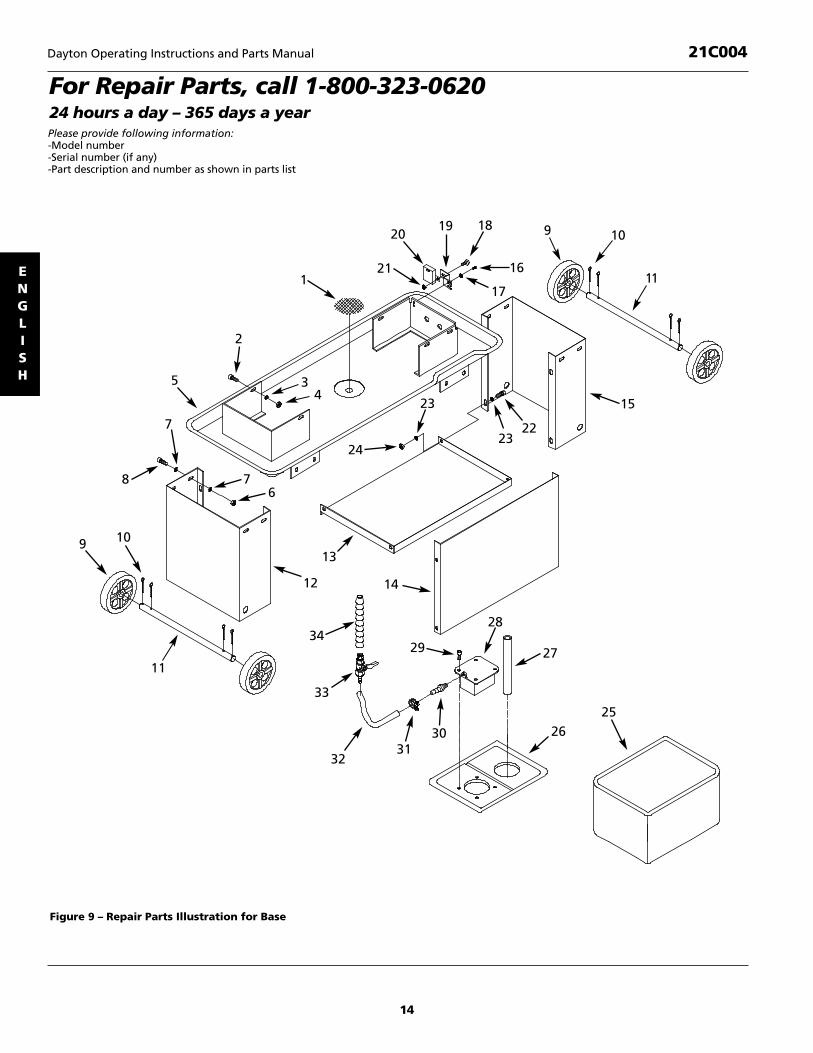
For Repair Parts, call 1-800-323-062024 hours a day – 365 days a year
11
109
8
24
34
23
2322
15
7
19 18
16
17
20
211
2
5
76
12
34
14
13
33
3231
30
29
28
27
2625
Please provide following information:-Model number-Serial number (if any)-Part description and number as shown in parts list
Figure 9 – Repair Parts Illustration for Base
9 10
11

15
Repair Parts List for Base
Dayton Operating Instructions and Parts Manual 21C004
ENGLISH
1 Filter 36360.00 12 5/16-18 x 1-1/4” Hex Head Bolt * 83 5/16” Flat Washer * 84 5/16-18 Hex Nut * 85 Chip Tray † 16 3/8-16 Hex Nut * 87 3/8” Flat Washer * 168 3/8-16 x 1” Hex Head Bolt * 89 Wheel 36361.00 4
10 Cotter pin 36362.00 811 Axle 36363.00 212 Left Leg † 113 Shelf 36364.00 114 Panel † 115 Right Leg † 116 1/4-20 x 1/2” Pan Head Screw * 217 1/4” Flat Washer * 2
18 1/4-20 x 3/4” Pan Head Screw * 119 Bracket 36365.00 120 Limit Switch 36366.00 121 1/4-20 Hex nut * 122 5/16-18 x 5/8” Hex Head Bolt * 423 5/16” Flat Washer * 824 5/16-18 Hex Nut * 425 Coolant Tank 36367.00 126 Tank Cover 36368.00 127 Return Hose 36369.00 128 Pump 36370.00 129 5/16-18 x 1” Hex Head Bolt * 430 3/8” NPT hose fitting 36371.00 131 Hose Clamp 36372.00 232 Hose 36373.00 133 Valve 36374.00 134 Nozzle Assembly 36375.00 1
Ref. PartNo. Description No. Qty.
Ref. PartNo. Description No. Qty.
(*) Standard hardware item, available locally.(†) Not available as repair part.

16
Dayton Operating Instructions and Parts Manual 21C004
ENGLISH
For Repair Parts, call 1-800-323-062024 hours a day – 365 days a yearPlease provide following information:-Model number-Serial number (if any)-Part description and number as shown in parts list
Figure 10 – Repair Parts Illustration for Bed
32
13
30
31
21
39
38
37
35
34
33
336
21
12
29
17
21
41
40 12
28
27
26
24
2
3
25
17
16
2
23
1
2221
20
19
18
62
1
543
4
84
10
7
9
11
14
15
48

17
Repair Parts List for Bed
Dayton Operating Instructions and Parts Manual 21C004
ENGLISH
1 5/16-18 x 5/8” Hex Head Bolt * 62 5/16” Flat Washer * 63 3/8-16 Hex Nut * 34 3/8” Flat Washer * 55 Spring Bracket 36052.00 16 Eye Bolt 36053.00 17 Spring 36054.00 18 3/8-16 x 1-1/4” Hex Head Bolt * 39 Left Vise Jaw 36055.00 1
10 10-1.5 x 40mm Hex Head Bolt * 111 Right Vise Jaw 36056.00 112 1/2-13 x 2-1/2” Hex Head Bolt * 113 1/2-13 x 2-1/2” Carriage Bolt * 114 1/2” Flat Washer * 115 1/2-13 Hex Nut * 116 Pivot Bracket 36057.00 117 5/16-18 x 3/8” Set Screw * 218 Trip Plate 36058.00 119 1/4” Flat Washer * 120 1/4-20 x 1/2” Hex Head Bolt * 121 5/16-18 Hex Nut * 3
22 5/16-18 x 1” Hex Head Bolt * 123 3/8-16 x 2” Hex Head Bolt * 124 Strain Relief 36059.00 325 Plate 36060.00 126 Shaft 36061.00 127 Bushing 36062.00 128 Bracket 36063.00 129 Work Stop 36064.00 130 Work Stop Rod 36065.00 131 5/16” Lock Washer * 232 Bed † 133 5/16-18 x 1/2” Set Screw * 134 Handwheel 36066.00 135 Stop 36067.00 136 Support Plate 36068.00 137 5/8” Flat Washer * 138 Leadscrew 36069.00 139 Leadscrew Nut 36070.00 140 Cylinder Support 36317.00 141 Feed Cylinder Assembly 36318.00 1
Ref. PartNo. Description No. Qty.
Ref. PartNo. Description No. Qty.
(*) Standard hardware item, available locally.(†) Not available as repair part.

18
Dayton Operating Instructions and Parts Manual 21C004
ENGLISH
For Repair Parts, call 1-800-323-062024 hours a day – 365 days a yearPlease provide following information:-Model number-Serial number (if any)-Part description and number as shown in parts list
Figure 11 – Repair Parts Illustration for Head
23
10
44
2220
94
2145
19
18
50
49
48
6
2
1
47
46
87
53
4
910
11
12
1113
14
1716
15
910 30
2928
35
24
25
2627
9
33
19
32
3110
38
37
36
41
3534 43
25
43
4240
35
39

19
Repair Parts List for Head
Dayton Operating Instructions and Parts Manual 21C004
ENGLISH
1 Knob 36091.00 22 Blade Cover 36092.00 13 1/4” Flat Washer * 64 1/4-20 x 1/2” Round Head Screw * 85 Drive Wheel Cover 36093.00 16 Blade 36094.00 17 Retaining Ring 36095.00 18 Drive Wheel 36096.00 19 5/16-18 x 5/8” Hex Head Bolt * 6
10 5/16” Flat Washer * 711 6200ZZ Ball Bearing 07062.00 212 Tracking Wheel 36097.00 113 3BMI-35 Retaining Ring 07370.00 114 Bushing 36098.00 215 Knob 36099.00 116 Spacer 36316.00 117 Spring 36100.00 118 Shipping Bracket 36101.00 119 Guide Plate 36102.00 220 Tracking Wheel Shaft 36103.00 121 4 x 25mm Dowel Pin 36104.00 122 Tension Block 36105.00 123 5/16-18 x 1-3/4” Socket Head Bolt * 324 Left Guide Bar 36106.00 125 Knob 36107.00 2
26 Blade Guard 36108.00 127 #10-24 x 1/4” Round Head Screw * 228 Left Bracket 36109.00 129 3/8” Lock Washer * 430 3/8-24 Hex Nut * 431 5/16” Lock Washer * 232 5/16-18 x 1-1/4” Socket Head Bolt * 233 Pin 36110.00 234 Right Guide Bar 36111.00 135 6000zz Ball Bearing 04018.00 1036 Plate 36112.00 137 1/4-20 x 1/2” Flat Head Screw * 238 Bearing Shaft 36113.00 239 3AMI-10 Retaining Ring 00221.00 440 Eccentric Shaft 36114.00 241 Right Bracket 36115.00 142 Brush Assembly 36116.00 143 5/16-18 x 1” Hex Head Bolt * 344 Bracket 36117.00 145 Bracket 36118.00 146 #8-32 x 3/8” Hex Head Bolt * 347 Bearing Cover 36119.00 148 Switch Box 36120.00 149 Main Switch 36121.00 150 Pump Switch 36122.00 1
Ref. PartNo. Description No. Qty.
Ref. PartNo. Description No. Qty.
(*) Standard hardware item, available locally.(∆) Not shown.

20
Dayton Operating Instructions and Parts Manual 21C004
ENGLISH
For Repair Parts, call 1-800-323-062024 hours a day – 365 days a yearPlease provide following information:-Model number-Serial number (if any)-Part description and number as shown in parts list
Figure 12 – Repair Parts Illustration for Gear Box
4
5
30
39
40
37
27
10
21
2425
22 23
3313
3436
38
3532
31
3
2
7
3
6
1
8
2627
2826
29
13
12
1819
15
20
14
9
10
11
17
8
16

21
Repair Parts List for Gear Box
Dayton Operating Instructions and Parts Manual 21C004
ENGLISH
(*) Standard hardware item, available locally.(∆) Not shown.
(†) Not available as repair part.
1 V-Belt A-650 36071.00 12 Motor Pulley 36072.00 13 1/4-20 x 3/8” Set Screw * 44 Pulley Cover 36073.00 15 Screw with washer 36074.00 16 Driven Pulley 36075.00 17 1/4-20 x 1/2” Pan Head Screw * 38 1/4” Flat Washer * 59 3AMI-17 Retaining Ring 00341.00 1
10 6003z Ball Bearing 05092.00 411 5/16-18 x 3/8” Set Screw * 112 Bushing 36076.00 113 6003zz Ball Bearing 04838.00 214 3/8-16 x 1-1/4 Hex Head Bolt * 415 3/8” Lock Washer * 416 1/4-20 x 1/2” Round Head Screw * 217 Cover 36077.00 118 5 x 5 x 55mm Key 15781.00 119 Worm Shaft 36078.00 120 Gear Box Housing † 121 Motor Mount Bracket 36079.00 122 1/4-20 x 1” Hex Head Bolt * 123 1/4-20 Hex Nut * 124 5/16” Flat Washer * 425 5/16-18 x 1/2” Hex Head Bolt * 4
26 3/8-16 Hex Nut * 427 3/8” Flat Washer * 828 Motor Mount Plate 36080.00 129 3/8-16 x 2-1/4” Hex Head Bolt * 130 5 x 5 x 40mm Key 07885.00 131 Motor 36081.00 132 3/8-16 x 1” Hex Head Bolt * 433 Bushing 36082.00 134 Bushing 36083.00 135 5 x 5 x 20mm Key 00537.00 136 Gearshaft Assy 36084.00 137 Gasket 36085.00 138 Gearbox Cover 36086.00 139 Vent Bolt 36087.00 140 1/4-20 x 5/8” Hex Head Bolt * 4Δ� Complete Gearbox Assy. 36088.00 1Recommended AccessoriesΔ� Material support stand 6Z765 1Δ� Magnetic base light 4PD35 1Δ� 1 Gallon cutting fluid 4KYP3 1Δ� 1 Quart industrial gear oil 4ZF30 1Δ� 3/4” Bi-metal, 5-8 TPI 4WE14 1Δ� 3/4” Bi-metal, 6-10 TPI 4WE15 1Δ� 3/4” Bi-metal, 10-14 TPI 4WE13 1
Ref. PartNo. Description No. Qty.
Ref. PartNo. Description No. Qty.

Dayton Operating Instructions and Parts Manual
Dayton 7 x 12” Metal Cutting Band Saw
21C004
®
ENGLISH
LIMITED WARRANTY
DAYTON ONE-YEAR LIMITED WARRANTY. DAYTON® 7 X 12” METAL CUTTING BAND SAW, MODELS COVERED IN THIS MAN-UAL, ARE WARRANTED BY DAYTON ELECTRIC MFG. CO. (DAYTON) TO THE ORIGINAL USER AGAINST DEFECTS IN WORKMAN-SHIP OR MATERIALS UNDER NORMAL USE FOR ONE YEAR AFTER DATE OF PURCHASE. ANY PART WHICH IS DETERMINED TO BE DEFECTIVE IN MATERIAL OR WORKMANSHIP AND RETURNED TO AN AUTHORIZED SERVICE LOCATION, AS DAYTON DESIGNATES, SHIPPING COSTS PREPAID, WILL BE, AS THE EXCLUSIVE REMEDY, REPAIRED OR REPLACED AT DAYTON’SOPTION. FOR LIMITED WARRANTY CLAIM PROCEDURES, SEE “PROMPT DISPOSITION” BELOW. THIS LIMITED WARRANTYGIVES PURCHASERS SPECIFIC LEGAL RIGHTS WHICH VARY FROM JURISDICTION TO JURISDICTION.
LIMITATION OF LIABILITY. TO THE EXTENT ALLOWABLE UNDER APPLICABLE LAW, DAYTON’S LIABILITY FOR CONSEQUENTIALAND INCIDENTAL DAMAGES IS EXPRESSLY DISCLAIMED. DAYTON’S LIABILITY IN ALL EVENTS IS LIMITED TO AND SHALL NOTEXCEED THE PURCHASE PRICE PAID.
WARRANTY DISCLAIMER. A DILIGENT EFFORT HAS BEEN MADE TO PROVIDE PRODUCT INFORMATION AND ILLUSTRATETHE PRODUCTS IN THIS LITERATURE ACCURATELY; HOWEVER, SUCH INFORMATION AND ILLUSTRATIONS ARE FOR THE SOLEPURPOSE OF IDENTIFICATION, AND DO NOT EXPRESS OR IMPLY A WARRANTY THAT THE PRODUCTS ARE MERCHANTABLE,OR FIT FOR A PARTICULAR PURPOSE, OR THAT THE PRODUCTS WILL NECESSARILY CONFORM TO THE ILLUSTRATIONS ORDESCRIPTIONS. EXCEPT AS PROVIDED BELOW, NO WARRANTY OR AFFIRMATION OF FACT, EXPRESSED OR IMPLIED, OTHERTHAN AS STATED IN THE “LIMITED WARRANTY” ABOVE IS MADE OR AUTHORIZED BY DAYTON.
Technical Advice and Recommendations, Disclaimer. Notwithstanding any past practice or dealings or trade custom,sales shall not include the furnishing of technical advice or assistance or system design. Dayton assumes no obligations or liability on account of any unauthorized recommendations, opinions or advice as to the choice, installation or use of products.
Product Suitability.Many jurisdictions have codes and regulations governing sales, construction, installation, and/or use ofproducts for certain purposes, which may vary from those in neighboring areas. While attempts are made to assure thatDayton products comply with such codes, Dayton cannot guarantee compliance, and cannot be responsible for how the product is installed or used. Before purchase and use of a product, review the product applications, and all applicable national and local codes and regulations, and be sure that the product, installation, and use will comply with them.
Certain aspects of disclaimers are not applicable to consumer products; e.g., (a) some jurisdictions do not allow the exclusionor limitation of incidental or consequential damages, so the above limitation or exclusion may not apply to you; (b) also,some jurisdictions do not allow a limitation on how long an implied warranty lasts, consequently the above limitation may not apply to you; and (c) by law, during the period of this Limited Warranty, any implied warranties of implied merchantability or fitness for a particular purpose applicable to consumer products purchased by consumers, may not beexcluded or otherwise disclaimed.
Prompt Disposition. A good faith effort will be made for prompt correction or other adjustment with respect to any product which proves to be defective within limited warranty. For any product believed to be defective within limited warranty, first write or call dealer from whom the product was purchased. Dealer will give additional directions. If unable toresolve satisfactorily, write to Dayton at address below, giving dealer’s name, address, date, and number of dealer’s invoice,and describing the nature of the defect. Title and risk of loss pass to buyer on delivery to common carrier. If product wasdamaged in transit to you, file claim with carrier.
Manufactured for Dayton Electric Mfg. Co., 100 Grainger Parkway, Lake Forest, Illinois 60045 U.S.A.

Impreso en EE.UU.080900306/042/VCPVP
36005.00-0812
Sierra de Banda de 18 x 30 cmpara Cortar Metales Dayton
Manual de Instrucciones de Operación y Lista de Partes 21C004
Por favor lea y guarde estas instrucciones. Léalas cuidadosamente antes de tratar de montar, instalar, operar o dar mantenimiento al productoaquí descrito. Protéjase usted mismo y a los demás observando toda la información de seguridad. ¡El no cumplir con las instrucciones puedeocasionar daños, tanto personales como a la propiedad! Guarde estas instrucciones para referencia en el futuro.
Formulario 5S5525
®
DescripciónLa Sierra de Banda Horizontal Dayton de 18 x 30 cm para Cortar Metales propor-ciona velocidad y calidad de corte para talleres de manufactura y maquinaria,departamentos de mantenimiento y contratistas. La velocidad de la hoja varíadesde 41 a 120 metros por minuto (MPM) a fin de cortar material tan variado comohierro colado, acero para herramientas, bronce, aluminio y plástico.
La velocidad de alimentación está regulada por medio de un cilindro hidráulico. Esposible tener acceso al cuadrante de control del cilindro en todo momento durantela operación respectiva y puede ajustarse a cualquier velocidad de alimentacióndentro de sus límites. La operación de corte con enfriamiento por agua ofrece uncorte de calidad y aumenta la vida de la hoja. Las características de la sierraincluyen un interruptor automático, un reductor de velocidad de tipo industrial,chasis, volantes, poleas, cabezal y base fabricados con acero de grueso calibre.
Las características adicionales incluyen prensas giratorias para cortes en ángulo,bandeja incorporada para virutas y conjuntos de ruedecillas. La sierra es controladapor medio de un interruptor basculante.
IMPORTANTE: La base viene revestidacon un protector. Para garantizar unajuste y un funcionamiento correctos,retire dicho revestimiento. Éste puedeeliminarse fácilmente con solventesminerales suaves y un paño suave. Eviteel contacto de disoluciones de limpiezacon la pintura o con cualquier parte degoma o plástico. Los solventes puedendeteriorar estos acabados. Use agua yjabón en la pintura y en los compo-nentes de plástico o goma. Después delimpiar, cubra con una película delgadade aceite todas las superficies expuestas.Se recomienda el uso de cera en pastapara la parte superior de la base.
Nunca use solventesaltamente volátiles.
Se recomienda utilizar solventes noinflamables para evitar posibles riesgosde incendio.
EspecificacionesCapacidad................Recorridos de 18 cm
Recorridos de 10 cm a 45ºRectángulo de 18 x 29 cm a 90º Rectángulo de 10 x 17 cm a 45º
Motor .............................1 HP, 1725 RPM,110V, 9.6 A, 60 Hz
Velocidades de hojas de corte........41, 49, 69 y 120 mpm
Medida de la hoja de corte .............1,9 x 0,09 x 236 cm
Volantes de la hoja de corte ............29 cm de diámetro
de hierro colado
Dimensionestotales ......................125,7 x 54,6 x 99 cm
Tamaño de le caja........126 x 46 x 108 cm
Peso ............................................... 145 kg
Peso de envio..................................175 kg
Bomba del enfriador....................9,8 lpm
Capacidad deldepósito del enfriador ...............8,5 litros
DesempaqueConsulte la Figura 1.
Revise para verificar si han ocurridodaños durante el envío. De ser así,deberá enviarse de inmediato una re -clamación a la compañía transportista.Revise para verificar si todo está com-pleto. Informe inmediatamente al dis-tribuidor si faltan partes.
La sierra de banda viene totalmenteensamblada como una unidad. Seránecesario localizar y ver que no faltenlas partes adicionales que deben mon-tarse en la sierra, antes de instalarlas:
A Conjunto del cilindro
B Varilla de soporte del cilindro contuerca hexagonal
C Perno de cabeza hexagonal, 5/16-18 x 1 pulg.
D Eje (2)
E Rueda (4)
F Pasador de aletas (8)
G Tope de seguridad con tornillo defijación
H Varilla del tope de seguridad contuerca hexagonal y dos arandelas deseguridad
I Filtro
J Manguera de retornoSi se utiliza equipode elevación de
cargas, tenga cuidado de no tocar líneasde alimentación eléctrica, tuberías,luminarias, etc. La sierra de banda pesaaproximadamente 145 kg.; deben usarseherramientas y equipos apropiados, ysolamente personal calificado debeemplearse en todas las fases del desem-balaje y la instalación.
ESPAÑOL
Figura 1 – Desempaque
A
C
E D
F
I
JH
B
G

Información de SeguridadGeneral
Para su propiaseguridad, 3antes
de poner en funcionamiento la herra -mienta, lea todas las instrucciones yprecauciones incluidas en este manual.
Parte del polvo pro-ducido por el lijado
mecánico, serrado, esmerilado, taladra-do y otras tareas de construcción con-tiene sustancias químicas que se sabeque pueden ocasionar cáncer, malfor-maciones congénitas u otros dañosreproductivos.
Algunos ejemplos de estas sustanciasquímicas son:
1. Plomo proveniente de pinturas conbase de plomo.
2. Sílice cristalino proveniente de ladril-los, cemento y otros materiales demampostería.
3. Arsénico y cromo proveniente demadera químicamente tratada.
El riesgo debido a la exposición a estas sustancias químicas depende de lafrecuencia con la cual realice este tipode trabajo. Para reducir la exposición aestas sustancias químicas: trabaje en unárea bien ventilada y utilice equipo deseguridad aprobado. Cuando trabajecon este tipo de herramientas, siempreutilice una máscara para la cara o respi-rador adecuadamente ajustados,aprobados por OSHA/NIOSH.
Siempre siga losprocedimientos de
manejo correctos, tal como se definenen este manual —, aun cuando estéfamiliarizado con el uso de esta herra -mienta o de otras similares. Recuerdeque un descuido por pequeño que seapuede producir lesiones personalesgraves.
ESTE PREPARADO PARA EL TRABAJO1. Use ropa adecuada. No use ropa
suelta, guantes, corbatas, anillos,pulseras u otras joyas que puedanquedar atrapadas en alguna piezamovible de la máquina.
2. Use una cubierta protectora para elcabello, para sujetar el cabello largo.
3. Use zapatos de seguridad con suelasantideslizantes.
4. Use gafas de seguridad que cumplancon la norma ANSI Z87.1 de los EstadosUnidos. Los anteojos comunes tienenlentes que sólo son resistentes al im -pacto. No son anteojos de seguridad.
5. Use una mascarilla completa o unamáscara contra el polvo, si al cortarcon la sierra se produce mucho polvo.
6. Esté alerta y piense claramente.Nunca opere herramientas mecánicascuando esté cansado, ebrio o cuandoesté tomando medicamentos quecausen somnolencia.
PREPARACION DEL AREA PARA EJECUTAR EL TRABAJO1. Mantenga el área limpia. Las áreas
de trabajo desordenadas atraen accidentes.
2. No use herramientas mecánicas enambientes peligrosos. No use herra -mientas mecánicas en lugares húme-dos o mojados. No exponga a la lluvialas herramientas mecánicas.
3. El área de trabajo debe estar ilumina-da adecuadamente.
4. Debe haber disponible un tomaco -rriente adecuado para la herramien-ta. Inserte el enchufe monofásico de120 voltios directamente en un recep-táculo de tres puntas debidamenteconectado a tierra.
5. Los cordones de extensión debentener una punta de conexión a tierray los tres alambres del cordón deextensión deben ser del calibreapropiado.
6. Mantenga a los visitantes a una dis-tancia prudente del área de trabajo.
7. Mantenga a los niños fuera del lugarde trabajo. Haga que su taller sea aprueba de niños. Use candados ointerruptores principales para evitarel uso no intencional de las her-ramientas mecánicas.
SE DEBE DAR MANTENIMIENTO ALAS HERRAMIENTAS1. Siempre desenchufe la herramienta
antes de inspeccionarla.
2. Consulte el manual para informarsesobre los procedimientos de mante -nimiento y ajuste específicos.
3. Mantenga la herramienta lubricada ylimpia de modo que funcione de lamanera más segura.
4. Retire las herramientas de ajuste.Antes de encender la máquina, veri-fique siempre si se han retirado lasherramientas de ajuste. Procure for-marse este hábito.
5. Mantenga todas las partes listas parafuncionar. Revise para determinarque el protector u otras partes ope -rarán correctamente y harán el traba-jo para el cual fueron fabricados.
6. Verifique si hay partes dañadas.Revise para verificar el alineamientode las partes movibles, si hay atasca -miento, roturas y montaje o cualquierotra condición que pudiera afectar laoperación de la herramienta.
7. Si hay una protección o cualquier otraparte dañada, éstas deberán reparar -se correctamente o ser reemplazadas.No haga reparaciones provisionales.(Cuando haga el pedido de las partesde reparación utilice la lista de partesincluida en el manual.)
SE DEBE CONOCER EL FUNCIONA MIENTO DE LA HERRAMIENTA1. Use la herramienta correcta para
cada trabajo. No fuerce la herra -mienta ni el accesorio, ni los usepara un trabajo para el cual no hansido diseñados.
2. Antes de cambiar la hoja, desenchu-far la herramienta.
3. Evite que la herramienta se enciendaaccidentalmente. Asegúrese de queel interruptor de la herramienta estéen la posición OFF (apagado) antesde enchufarla.
2-Sp
Manual de Instrucciones de Operación y Lista de Partes Dayton
Sierra de Banda de 18 x 30 cm paraCortar Metales Dayton®
21C004
ESPAÑOL

Información de SeguridadGeneral (Continuación)4. No fuerce la herramienta. Ésta traba-
jará de manera más eficiente a la ve -locidad para la cual ha sido diseñada.
5. Mantenga las manos alejadas de laspartes movibles y de las superficiesde corte.
6. Nunca deje desatendida una he rra -mienta en funcionamiento. Desco -néctela y no se aleje de ella hastaque ésta se haya detenido comple -tamente.
7. No trate de alcanzar demasiadolejos. Párese bien y mantenga siem-pre un buen equilibrio.
8. Nunca se pare sobre la herramienta.Podrían sufrirse graves lesiones siésta llegara a volcarse o si ustedtocara accidentalmente la hoja de la sierra.
9. Conozca su herramienta. Aprenda laaplicación de la herramienta y limi -taciones específicas.
10. Use los accesorios recomendados.(Consulte la página 21.) Si se usanaccesorios erróneos, puede sufrirlesiones o lesionar a alguien.
11. Manipule correctamente la pieza detrabajo. Protéjase las manos contrala posibilidad de lesiones.
12. Si la máquina se atasca, apáguelainmediatamente. La hoja se atasca sipenetra demasiado en la pieza detrabajo. (La fuerza del motor lamantendrá atascada en la pieza detrabajo.) No retire las piezas atas-cadas o cortadas hasta que se hayaapagado y desconectado la sierra yla hoja se haya detenido.
¡Piense en laseguridad! La segu -
ridad es una combinación del sentidocomún del operador y de estar alerta entodo momento al usar la herramienta.
MontajeNo trate de operarla herramienta
hasta que haya sido completamentearmada según las instrucciones.
INSTALACION DE LOS CONJUNTOSDE RUEDA
Consulte la Figura 9.
1. Eleve y sostenga la pata derecha (Ref.No. 15) aproximadamente 7,6 cm.Apoye la sierra en la pata únicamente.No utilice el estante para apoyar lasierra. Deslice el eje (Ref. No. 11) através de los agujeros en la pata.
2. Inserte el pasador de aletas (Ref. No.10) en el agujero interior del eje.Doble el extremo del pasador de ale-tas hacia atrás para fijarlo en su lugar.Deslice la rueda (Ref. No. 9) sobre eleje. Inserte el pasador de aletas en elagujero exterior del eje y doble elextremo del pasador de aletas haciaatrás para fijarlo en su lugar.
3. Repita el paso 2 para el otro extremodel eje.
4. Repita los pasos 1, 2 y 3 para la pataizquierda.
INSTALACION DEL CONJUNTO DELCILINDROConsulte las Figuras 10 y 11.
1. Se debe retirar el soporte de embar-que (Figura 11, Ref. No. 18). Retire elperno y la arandela (Figura 11, Refs.No. 9 y 10) y el tope con tuercahexagonal (Figura 10, Refs. No. 3 y35). Guarde el soporte, éste será nece-sario si se transporta la sierra posteri-ormente. Vuelva a instalar el tope contuerca hexagonal en la sierra.
2. Enrosque la varilla de soporte delcilindro en la bancada (Figura 10,Refs. No. 40 y 32).
3. Deslice el agujero inferior del conjun-to del cilindro (Figura 10, Ref. No. 41)sobre la varilla de soporte del cilindroy fíjelo en posición usando la tuercahexagonal (Figura 10, Ref. No. 21).
4. Instale la varilla del conjunto del cilin-dro en el soporte usando un perno de
cabeza hexagonal (Figura 11, Refs.No. 43 y 44).
INSTALACION DEL FILTRO Y LAMANGUERA DE RETORNOConsulte la Figura 9.
1. Inserte el filtro (Ref. No. 1) en el orifi-cio de drenaje central de la bandejade virutas (Ref. No. 5).
2. Conecte un extremo de la manguerade retorno (Ref. No. 27) en la parteinferior del orificio de drenaje de labandeja de virutas e inserte el otroextremo en el tanque de refrigerante(Ref. No. 25).
INSTALACION DEL TOPE DE SEGURIDADConsulte la Figura 10.
1. Inserte la varilla del tope de seguridadcon una arandela de seguridad (Refs.No. 30 y 31) en la bancada. Fije la var-illa en posición con una arandela deseguridad y una tuerca hexagonal(Refs. No. 21 y 31) instaladas en la var-illa por el lado inferior de la bancada.
2. Instale el tope de seguridad (Refs. No.29) en la varilla y fíjelo en posicióncon el tornillo de fijación (Ref. No. 17).
INSTALACION DEL INTERRUPTOR DESEGURIDADConsulte las Figuras 9 y 10.
El interruptor de seguridad (Figura 9,Ref. No. 20) apaga la sierra cuando elinterruptor hace contacto con la placade disparo (Figura 10, Ref. No. 18). Elinterruptor de seguridad se debe activarcuando la hoja de la sierra ya ha pasadoa través del plano de la bancada de tra-bajo y el corte ha finalizado.
1. Eleve el cabezal varios centímetros ycierre la válvula que está en el cilin-dro para mantener el cabezal en unaposición elevada.
2. Instale el conjunto del interruptor deseguridad (Figura 9, Refs. No. 19 y 20)en la bancada usando tornillos decabeza de placa y arandelas (Figura 9,Refs. No. 16 y 17).
Modelo 21C004
3-Sp
ESPAÑOL
Manual de Instrucciones de Operación y Lista de Partes Dayton

Montaje (continuación)3. Conecte la sierra al suministro eléctri-
co, encienda la sierra, abra la válvuladel cilindro y deje que el cabezal ali-mente hacia abajo hasta que la sierrase apague.
4. Observe la posición de la hoja de lasierra. La parte superior de la hojadebe estar por debajo de la mesa dela bancada. Si es necesario, ajuste eltope (Figura 10, Ref. No. 35) para quela hoja esté por debajo de la bancadade trabajo al final del recorrido delcabezal.
InstalaciónConsulte las Figuras 2 y 3.
No trate de instalarla herramienta si le
faltan piezas. Guíese con el manual parahacer el pedido de partes de reparación.
Antes de instalar la sierra de banda debeseleccionarse un lugar adecuado. La sierrapesa aproximadamente 144 kg.
1. Será necesario colocar la sierra debanda sobre una superficie plana ynivelada.
2. Asegúrese de que exista suficienteespacio para la pieza de trabajo.
3. Asimismo, será necesario contar conuna iluminación adecuada y corrienteeléctrica correcta para el área de trabajo.
FUENTE DE ENERGIALa sierra de banda viene configuradapara una fuente de alimentación eléctri-ca de 120V, 60 Hz.
Solamente un elec-tricista profesional
debe realizar las conexiones eléctricas.
Conecte la sierra debanda a la fuente
de alimentación eléctrica solamentedespués de llevar a cabo todos lospasos de ensamblaje.
El motor está diseñado para funcionar alvoltaje y frecuencia especificados. Las car-gas normales serán manejadas en formasegura aún si el voltaje es un 10% mayoro menor que el voltaje especificado.
El hacer funcionar la unidad con volta-jes fuera de los límites especificadospuede calentar excesivamente la he -rramienta y quemar el motor. Para cargas pesadas es necesario que elvoltaje en los terminales del motor nosea menor que el voltaje especificado.
La sierra de banda viene precableadapara funcionar con 120 voltios.
INSTRUCCIONES PARA LA CONEXIONA TIERRA
Si la conexión atierra del equipo se
realiza erróneamente podría ocurrir unadescarga eléctrica. Mientras se esté uti-lizando, el equipo deberá estar conecta-do a tierra a fin de proteger al operadorcontra una descarga eléctrica.
Si no entiende las instrucciones deconexión a tierra o si tiene dudas sobrela conexión correcta a tierra de la he -rramienta, consulte con un electricistaprofesional.
A fin de protegerle contra una descargaeléctrica, esta herramienta está equipa-da con un cable de tres conductoresaprobado con capacidad para 250V, yun enchu fe de tres clavijas con conexióna tierra con capacidad para 125V (Vea laFigura 2).
El enchufe de conexión a tierra deberáconectarse directamente a un recep-táculo para 3 clavijas instalado y conec-tado debidamente a tierra, tal como semuestra en la Figura 2.
No retire ni modifique en forma alguna
laclavija de conexión a tierra. En caso deun mal funcionamiento o un desperfec-to, la conexión a tierra proporciona unaruta de mínima resistencia para ladescarga eléctrica.
Al conectar odesconectar el
enchufe del tomacorriente, no permitaque sus dedos toquen las clavijas.
El enchufe debe conectarse en el toma-corriente correspondiente que haya sidoinstalado y conectado a tierra debida-mente, de conformidad con todos loscódigos y reglamentaciones locales. Nomodifique el enchufe proporcionado. Sino encaja en el tomaco rriente, solicite aun electricista profesional que instaleun tomacorriente adecuado.
Revise periódicamente los cordones dela herramienta, si están dañados, lléve-los a un centro de servicio autorizadopara que los reparen.
El conductor verde (o verde y amarillo)del cable es para la conexión a tierra. Si esnecesario reparar o reemplazar el cordónde alimentación, no conecte el alambrede color verde (o verde y amari llo) a unterminal energizado.
Si se cuenta únicamente con un toma-corriente para dos clavijas, éste deberáser reemplazado con uno para tres cla -vijas debidamente conectado a tierra einstalado de conformidad con el CódigoEléctrico Nacional (National ElectricCode), y los códigos y reglamentoslocales.
Esta tarea deberáser realizada por
un electricista profesional.
Hay disponible un adaptador temporalde conexión a tierra con tres clavijaspara un tomacorriente de dos clavijas(Vea la Figura 3); con éste él podráconectar enchufes a un tomacorrientebipolar si el mismo se encuentra debida-mente conectado a tierra.
4-Sp
ESPAÑOL
Sierra de Banda de 18 x 30 cm paraCortar Metales Dayton®
Manual de Instrucciones de Operación y Lista de Partes Dayton 21C004
Figura 2 – Receptáculo de 3 puntas
Tomacorriente conectadoa tierra correctamente
Enchufe de3 puntas
Punta de conexión a tierra
Talón de tierra
Adaptador
Enchufe de 3 puntas
Receptáculode 2 puntas
Asegúreseque estéconectado auna conexióna tierra conocido
Figura 3 – Receptáculo de 2 puntas con adaptador

Instalación (Continuación)No utilice adaptadores de 3 clavijas a 2,a menos que así lo permitan los códigosy normativas nacionales y locales.
(El uso de este tipo de adaptadores noestá permitido en Canadá.) Cuando estépermitido utilizar este tipo de adapta-dores, la lengüeta rígida de color verdeo el terminal en el lado del adaptadordeberá estar bien conectado a una tie -rra permanente, como sería una tuberíapara cañería debidamente conectada atierra, una caja de distribución debida-mente conectada a tierra o un sistemade alambres también debidamenteconectado a tierra.
Muchos de los tornillos para placas decubierta, las tuberías para cañería y lascajas de distribución no están debida-mente conectados a tierra. Para garan -tizar una conexión correcta a tierra, los dispositivos de conexión deberán ser aprobados por un electricista pro fesional.
CORDONES DE EXTENSION1. El uso de cualquier tipo de cordón de
extensión ocasionará una caída en elvoltaje y una pérdida de potencia.
2. Los alambres del cordón de extensióndeben tener el tamaño suficientepara transportar la corriente adecua-da y mantener el voltaje correcto.
3. Utilice la tabla para determinar eltamaño mínimo del alambre (según lanorma AWG) del cordón de extensión.
4. Utilice únicamente cordones deextensión trifilares con enchufes conconexión a tierra, de tres clavijas, ytomacorrientes tripolares y compa tiblescon el enchufe de la herra mienta.
5. Si el cordón de extensión está desgas-tado, roto o dañado de alguna ma -nera, reemplácelo inmediatamente.
LONGITUD DEL CORDON DE EXTENSION(120 VOLTIOS)Tamaño del Cable A.W.G.
Hasta 7,6 m............................................187,6 m a 15,2 m.......................................1615,2 m a 30,4 m.....................................14
30,4 m a 45,6 m.....................................12
AVISO: No se recomienda el uso de cor-dones de extensión más largos de 45,6 metros.
OperaciónConsulte las Figuras 4-12.
La gama de velocidades de la hoja de lasierra de banda horizontal de 18 x 30 cmy 4 velocidades es de 41 a 120 metros porminuto.
Las mordazas del tornillo de bancopueden girarse de 0° a 45º para hacercortes en inglete. Las mordazas movi-bles pueden acercarse o alejarse rápida-mente.
Siempre observe las precauciones
de seguridad siguientes.
1. Al ajustar o cambiar piezas de la sierra de banda, siempre apague launidad y desconecte el enchufe deltomacorriente.
2. Asegúrese de que los topes esténcolocados y que funcione el inte -rruptor automático.
3. Verifique que la caja de engranajestenga la cantidad correcta de lubri-cante.
4. Asegúrese de colocar correctamentelas guías de la hoja.
5. Utilice la hoja apropiada para la piezaque se va a cortar.
6. Utilice una hoja afilada. Cambie lashojas gastadas o aquéllas con dientesrotos.
7. Asegúrese de que la hoja tenga latensión apropiada y que ésta avanceen la dirección correcta.
8. Utilice la velocidad adecuada de hojapara el trabajo que esté realizando.
9. A fin de lograr un óptimo rendi -miento, no detenga el motor nireduzca su velocidad. Use la presiónadecuada de alimentación.
10. Asegúrese de contar con suficientecongelante para mantener sumergi-da la bomba del enfriador (Figura 8,Ref. No. 28).
11. Fije la pieza de trabajo en una posi-ción estable.
12. Compruebe que todos los protec-tores estén instalados.
13. Después de encender la unidad,espere hasta que la hoja alcance suvelocidad máxima. Después, bajelentamente la hoja hacia la pieza queva a cortar.
14. Mantenga las manos alejadas de lahoja y de todas las partes movibles.
15. Siempre use protección para los ojos.
TOPE HORIZONTALConsulte la Figura 10.
El tope horizontal (Ref. No. 35) controlala posición del cabezal al final del corte.El cabezal debe hacer contacto con eltope horizontal cuando los dientesestán a 3 mm por debajo de la superfi-cie de trabajo.
AJUSTE DEL TOPE HORIZONTALConsulte la Figura 10.
1. Coloque el cabezal en la posición horizontal.
2. Afloje las tuercas (Ref. No. 3) del topehorizontal.
3. Ajuste el tope horizontal hasta quelos dientes estén a 3 mm por debajode la superficie de trabajo.
4. Apriete las tuercas para fijar la posición.
INTERRUPTOR AUTOMATICOConsulte la Figura 9.
El disyuntor de seguridad (Ref. No. 20)se activa cuando la hoja pasa a travésdel plano de la bancada de trabajo.
El disyuntor de seguridad se deberáactivar tan pronto termine el corte.
IMPORTANTE: Asegúrese que la accióndel disyuntor de seguridad no se vealimitada por el tope horizontal.
LUBRICACION1. Todos los rodamientos de bola tienen
una lubricación permanente. No seránecesaria ninguna lubricación adi-cional.
Modelo 21C004
5-Sp
ESPAÑOL
Manual de Instrucciones de Operación y Lista de Partes Dayton
Operación (Continuación)2. Si se desmontan por algún motivo el
volante guía o el pivote del cabezal,limpie la grasa antes de ensamblarestos elementos.
NIVEL DE ACEITEConsulte la Figura 12.
1. La caja de engranajes depende de un baño de aceite para lubricar lassuperficies deslizantes y transferir elcalor. El perno de ventilación (Ref.No. 39) deja pasar el aire para reducirla presión creada por el calor genera-do. Una lubricación insuficiente haráque los engranajes se calienten y sedesgasten más rápidamente. Si la caja de engranajes tiene demasiadoaceite, el aceite caliente saldrá por el orificio de respiración. La caja deengranajes está diseñada para alojar284 gramos de aceite industrial paraengranaje con grado de viscosidad de70-95.
2. El nivel de aceite deberá permanecerconstante. Si el nivel cambia, deberáverificarse que no exista una junta osello defectuosos y deberán reem-plazarse si fuera necesario.
3. Si se trabaja con la caja de engrana-jes, será necesario cambiar el aceitepara evitar la contaminación de éste.
4. Siempre añada aceite nuevo y cám-bielo periódicamente para evitar des-perfectos.
5. Entre la caja de engranajes y las pla-cas de la cubierta se utiliza una empa-quetadura de sello (Ref. No. 14). Si se retira una placa de cubierta, seránecesario limpiar las superficies ycolocar una nueva empaquetadura.
6. Después de las primeras cincuentahoras de uso, será necesario drenar la caja de engranajes y llenarla conaceite industrial para engranajes(Modelo No. 4ZF30).
GUIAS DE LA HOJASerá necesario torcer la hoja de la sierrade banda en relación con el plano en el
cual gira. Será necesario que la hojaesté situada correctamente en relacióncon la base de trabajo.
Las guías de la hoja sujetan la parte cor-tante de la hoja en un plano perpendicu-lar tanto a la base de trabajo como altornillo estacionario y mantienen la hojaen línea con el trayecto normal de éstaalrededor de los volantes de la misma.
Los rodamientos internos de la guía enlos conjuntos de guía izquierdo y dere-cho mantienen la hoja en línea con losvolantes de la misma. Los rodamientosexternos de la guía mantienen la hojacontra los rodamientos internos.
Todo el conjunto de la guía se coloca ensu posición en la fábrica para lograr latorsión adecuada y no será necesarioajustarlo; sin embargo, deberá verifi-carse frecuentemente la posición de lasguías de la hoja.
NOTA: Debido a que la posición de lahoja está relacionada con la base y lasmordazas del tornillo, es importante laposición relativa de la mordaza conrespecto a la base. Cuando la unidad yaesté armada, la mordaza estacionariadeberá estar perpendicular a la superfi-cie de la base de trabajo.
VERIFICACION DE LAS GUIAS DE LAHOJAConsulte la Figura 11.
1. Verifique que los dientes de la hojaestén perpendiculares a la superficiemaquinada de la base.
2. Aleje las guías de la hoja lo más posible.
3. Compruebe que las mordazas deltornillo estén paralelas y ajustadaspara cortar a 90º.
4. Sitúe las mordazas para tener lamayor separación posible sin queéstas interfieran con las guías de lahoja.
5. Con el cabezal en posición horizon-tal, ponga una escuadra contra lacara de la mordaza posterior de laprensa y verifique que la mordaza
esté a 90º del lado de la hoja.
6. Compruebe que la hoja esté en líneacon los volantes de guía y de impul-sión (Refs. No. 8 y 12).
7. Levante el cabezal.
8. Centre la vista directamente en elborde cortante de la hoja.
9. Asegúrese de que los lados de lahoja estén paralelos a los lados delos rodamientos.
10. Asegúrese de que los rodamientos(Ref. No. 35) hagan contacto con lashojas pero todavía se puedan girarmanualmente.
AJUSTE DE LOS RODAMIENTOS DELAS GUIASConsulte la Figura 11.
Si la hoja no está perpendicular a labase o no está alineada con los volantesde la misma, será necesario ajustarla.
NOTA: Deberá existir una holgura de0,0000 a 0,0254 mm entre la hoja y losrodamientos de la guía.
Los rodamientos se ajustan mediante unsistema de ubicación con excéntricas.Los roda mien tos internos de la guíaestán fijos y no pueden ajustarse. Losrodamientos externos están montadossobre ejes excéntricos (Ref. No. 40) ypueden ajustarse.
1. Afloje las tuercas hexagonales (Ref.No. 30) con una llave. Gire el ejeexcéntrico para situar los rodamientosen la posición deseada.
2. Mantenga la posición del eje excéntri-co y apriete las tuercas hexagonales.
INSPECCION DE LOS RODAMIENTOSDE EMPUJEConsulte la Figura 11.
Los rodamientos de empuje (Ref. No.35) deberán estar a 0,0762 a 0,1270 mm(grosor promedio de una hoja de papel)de la parte posterior de la hoja.
Los rodamientos de empuje se ajustanmoviendo la abrazadera de la guía.
6-Sp
ESPAÑOL
Sierra de Banda de 18 x 30 cm paraCortar Metales Dayton®
Manual de Instrucciones de Operación y Lista de Partes Dayton 21C004

Operación (Continuación)AJUSTE DE LAS PIEZAS DE SOPORTEDE LAS GUIASConsulte la Figura 11.
1. Si los rodamientos se colocan correc-tamente y la hoja no está en ángulorecto, será necesario ajustar una oambas de las piezas de soporte de laguía de la hoja (Refs. No. 28 y 36).
2. Afloje los pernos de cabeza hueca(Ref. No. 32).
3. Ajuste la pieza de soporte a la posi-ción correcta.
4. Apriete los pernos de cabeza hueca.
5. Inspeccione los rodamientos de laguía. Todo ajuste de posición de lapieza de soporte de la guía de la hojapodrá alterar los ajustes anteriores.Reajuste si es necesario.
SELECCION DE LA HOJAEl uso de la hoja adecuada es importantepara establecer las condiciones correctaspara un corte. Las hojas son diferentesde acuerdo con el uso específico para elcual se hayan diseñado. Sin embargo,algunas reglas sencillas aun son aplica-bles para la mayoría de las hojas.
1. Siempre recuerde que durante uncorte será necesario tener por lomenos tres dientes en contacto con lapieza de trabajo. Cuando se tienentres dientes en contacto con la piezade trabajo, la hoja no se podrá mon-tar sobre la pieza de trabajo. Estoevita que un diente que entre en elcorte se encuentre con más materialdel que pueda retirar.
2. Se produce una “sacudida” cuando losdientes de la hoja entran en contactocon demasiado material. Esto puedeocasionar que se rompan los dientes.Para cortar materiales más duros, elnúmero mínimo sugerido de dientesen contacto es seis, ya que la “sacudi-da” en este tipo de materiales tendráun efecto más dañino sobre la hoja. Elnúmero óptimo de dientes en contac-to con el material de trabajo distribuyelas fuerzas que actúan sobre la hojaentre más dientes a fin de aumentar la
eficacia del corte y reducir el desgastede la hoja.
3. La cantidad óptima es de 6 a 12dientes en contacto para cortar mate-riales suaves y de 12 a 24 dientes paracortar los materiales más duros.
4. Mantenga en todo momento elnúmero máximo de dientes en elmate rial para evitar que los espaciosentre los dientes se llenen de material.
5. Al escoger una hoja, el tamaño totalde la pieza de trabajo no es tanimportante como su grosor promedio.El grosor promedio es la anchurapromedio del material con la cual lahoja entrará en contacto durantecada corte. La Figura 8, en la página10 describe cómo calcular el grosorpromedio.
6. Deberá utilizarse el grosor promediocuando se seleccione una hoja te -niendo en cuenta el número óptimode dientes en contacto; sin embargo,la regla de los tres dientes deberáaplicarse al grosor mínimo y no alpromedio.
7. Podrán lograrse mejores cortes si setienen a mano varias hojas afiladas.Las hojas durarán más porque serámenos probable que sean mal uti-lizadas si se cuenta con la hojaapropiada.
8. Todas las sierras de banda deberántener por lo menos una hoja de re -pues to de cada tipo que se use. No esposible predecir el momento en quese romperá una hoja. Consulte alfabrican te de hojas de corte paraobtener información detallada sobrelas hojas de corte existentes para usosespecíficos.
EXTRACCION DE LA HOJAConsulte la Figura 11.
Desconecte la sierrade banda del toma-
corriente al cambiar o ajustar las hojasde corte. Utilice guantes de cuero cuan-do trabaje con las hojas de la sierra debanda. Nunca utilice guantes cuandoopere la sierra.
1. Eleve el cabezal y abra la cubierta dela hoja.
2. Afloje los rodamientos externos de laguía en los conjuntos superior e infe-rior de la guía. No deberá moverseningún otro rodamiento de guía.
3. Con una mano junte la hoja y elvolante guía para protegerse contrala posibilidad de que la hoja salte alaflojar la tensión.
4. Afloje la tensión girando lentamentea la izquierda la manilla (Ref. No. 15).
5. Extraiga la hoja.
REEMPLAZO DE LA HOJA1. Asegúrese de que los rodamientos
externos de la guía estén sueltos.
2. Asegúrese de que los dientes apuntenen la dirección correcta (Vea la Figura 4).
3. Coloque la hoja alrededor de losvolantes y entre los rodamientos de laguía.
4. Mantenga la hoja en su posición co -rrecta y aplique tensión.
5. Empuje la hoja contra la pestaña delvolante.
6. Apriete la hoja hasta que ésta tengala tensión adecuada. Una hojadebidamente apretada tintineará ligeramente cuando se le da ungolpecito al lomo de la hoja (tal comosi fuera una cuerda de un instrumen-to musical).
7. Ajuste los rodamientos externos de laguía.
8. Verifique la alineación correcta (VeaAjuste de la Alineación).
Modelo 21C004
7-Sp
Figura 4 – Dirección de la Hoja
ESPAÑOL
Manual de Instrucciones de Operación y Lista de Partes Dayton

Operación (Continuación)ALINEACIONLa alineación correcta se logra cuandoel volante de impulsión y el volanteguía están alineados. Una hoja monta-da sobre volantes no alineados correcta-mente, podrá salirse de los volantes. Sibien un ajuste de la alineación solo seránecesario muy rara vez, la alineacióndeberá verificarse con frecuencia.
Apague el motor y desconecte la
alimentación eléctrica para verificar laalineación.
VERIFICACION DE LA ALINEACIONConsulte las Figuras 5 y 11.
1. Levante el cabezal. Abra la cubiertadel volante.
2. Inserte una hoja de papel entre lahoja y el lado izquierdo del volanteguía.
3. Deje que la hoja enganche el papel.Gire el volante de alineación (Figura11, Ref. No. 12) de manera que elpapel pase alrededor del volante.
4. Consulte la Figura 5 para determinarsi es necesario hacer un ajuste.
AJUSTE DE LA ALINEACIONConsulte las Figuras 5 y 11.
La alineación se ajusta mediante la colo-cación del eje del volante de alineación(Ref. No. 20). La colocación se hace conlos pernos superiores de cabeza huecaya están sueltos (Ref. No. 23).
1. Afloje los dos pernos de cabezahueca.
2. Ajuste la inclinación con los tornillosde ajuste. Para lograr la ali neacióncorrecta, refiérase a la Figura 5. Gire1/4 de vuelta a la vez.
3. Compruebe la tensión de la hoja yajústela si fuera necesario.
4. Vuelva a comprobar la alineación.
5. Una vez encontrada la posición ade-cuada, apriete firmemente los pernos.
VELOCIDAD DE LA HOJALa selección de la velocidad apropiadade la hoja es importante para prolongarla vida útil de la hoja. La velocidaddetermina la fuerza de corte disponible.
1. Los materiales duros requieren unamayor fuerza y se cortan a una menorvelocidad.
2. Los materiales suaves se cortan conmenos fuerza a mayores velocidadespara garantizar una eliminación ade-cuada de las virutas.
3. La velocidad y la fuerza correspon -diente están relacionadas con la po -tencia suministrada a la hoja. Hay cuatro velocidades disponibles.
4. Si se utiliza un motor diferente alsuministrado con la unidad, cam-
biarán las condiciones de corte.
5. Las velocidades y los materialescorrespon dientes se listan a contin-uación.
MPM41,2.....................Acero inoxidable, acero
de aleación
48,8.................Aceros al carbono medios a altos, latón duro
68,6....................Aceros al carbono bajos a medios, cobre
120,4 .........................Aluminio, plásticos,
CAMBIO DE LA VELOCIDADConsulte las Figuras 6 y 12.
1. Afloje el tornillo (Ref. No. 5) y abra lacubierta de las poleas (Ref. No. 4).
2. Afloje la tuerca hexagonal (Ref. No.26) y gire el perno de cabeza hexago-nal (Ref. No. 29) hacia la izquierdapara destensar la correa.
3. Mueva la correa V (Ref. No. 1) a laposición deseada en las poleas (Refs.No. 2 y 6).
4. Gire el perno de cabeza hexagonalhacia la derecha para tensar la correa.La correa estará debidamente tensa-da cuando se produce una desviaciónde 1,27 cm (1/2”) al aplicar una pre-sión moderada sobre la correa entrelas poleas. Apriete la tuerca hexago-nal para fijar la tensión de la correa.
5. Cierre y fije la cubierta de la polea.
8-Sp
ESPAÑOL
Sierra de Banda de 18 x 30 cm paraCortar Metales Dayton®
Manual de Instrucciones de Operación y Lista de Partes Dayton 21C004
Figura 5 – Ajustes de la Alineación
Si no hay doblez estoindica que la hoja se saldrá del volante.El tornillo de ajustedebe girarse a laderecha.
Un doblez muy pro-nunciado indica unaalineación correcta.
El papel cortado o rasgado indica que la hoja está chocandocontra la pestaña del volante. Seránecesa rio girar a laizquierda el tornillode ajuste.
395 (120)
225 (69)
160 (49)
135 (41)
Rueda de la hoja Motor
Velocidades de la hoja a PPM (M/MIN)
Figure 6 - Diagrama de velocidades y poleas
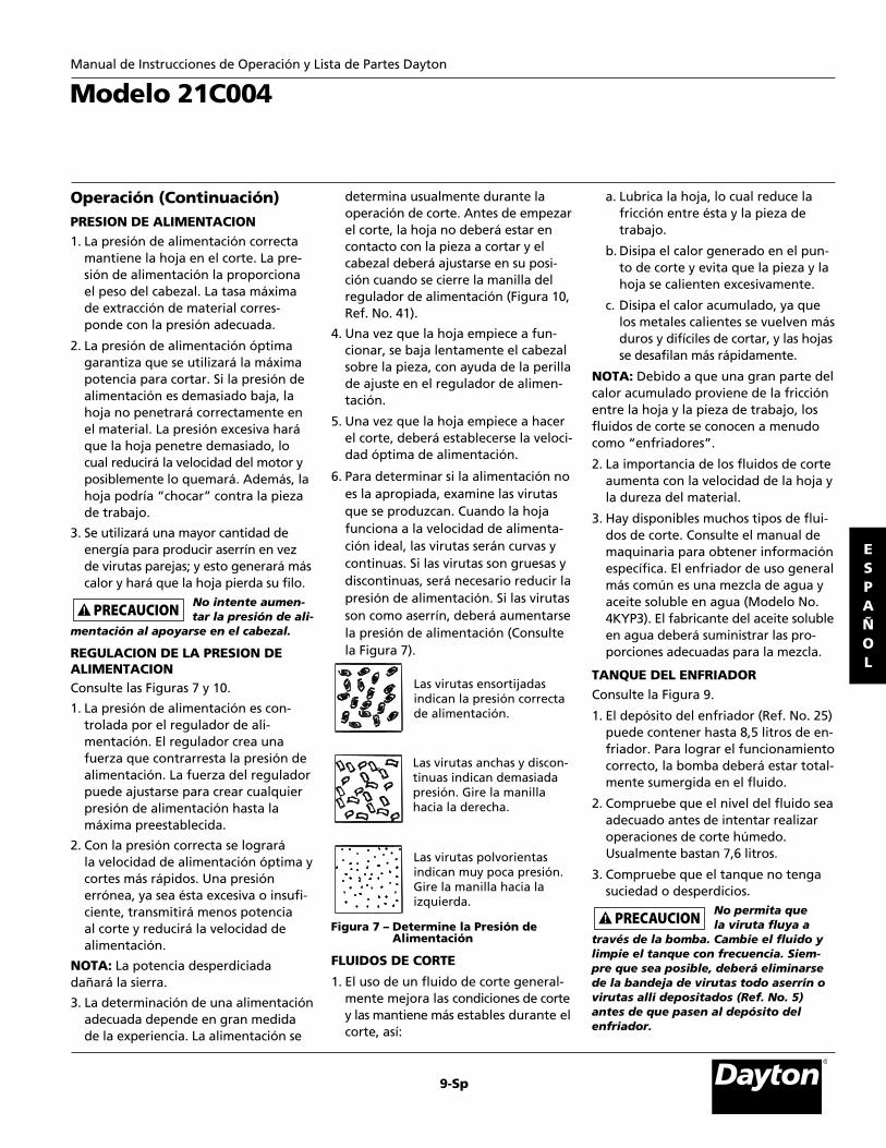
Operación (Continuación)PRESION DE ALIMENTACION1. La presión de alimentación correcta
mantiene la hoja en el corte. La pre-sión de alimentación la proporcionael peso del cabezal. La tasa máximade extracción de material corres -ponde con la presión adecuada.
2. La presión de alimentación óptimagarantiza que se utilizará la máximapotencia para cortar. Si la presión dealimentación es demasiado baja, lahoja no penetrará correctamente enel material. La presión excesiva haráque la hoja penetre demasiado, locual reducirá la velocidad del motor yposiblemente lo quemará. Además, lahoja podría “chocar” contra la piezade trabajo.
3. Se utilizará una mayor cantidad deenergía para producir aserrín en vezde virutas parejas; y esto generará máscalor y hará que la hoja pierda su filo.
No intente aumen-tar la presión de ali-
mentación al apoyarse en el cabezal.
REGULACION DE LA PRESION DE ALIMENTACIONConsulte las Figuras 7 y 10.
1. La presión de alimentación es con -trolada por el regulador de ali-mentación. El regulador crea unafuerza que contrarresta la presión dealimentación. La fuerza del reguladorpuede ajustarse para crear cualquierpresión de alimentación hasta la máxima preestablecida.
2. Con la presión correcta se logrará la velocidad de alimentación óptima ycortes más rápidos. Una presiónerrónea, ya sea ésta excesiva o insufi-ciente, transmitirá menos potencia al corte y reducirá la velocidad de alimentación.
NOTA: La potencia desperdiciadadañará la sierra.
3. La determinación de una alimentaciónadecuada depende en gran medidade la experiencia. La alimentación se
determina usualmente durante laoperación de corte. Antes de empezarel corte, la hoja no deberá estar encontacto con la pieza a cortar y elcabezal deberá ajustarse en su posi-ción cuando se cierre la manilla delregulador de alimentación (Figura 10,Ref. No. 41).
4. Una vez que la hoja empiece a fun-cionar, se baja lentamente el cabezalsobre la pieza, con ayuda de la perillade ajuste en el regulador de alimen -tación.
5. Una vez que la hoja empiece a hacerel corte, deberá establecerse la veloci-dad óptima de alimentación.
6. Para determinar si la alimentación noes la apropiada, examine las virutasque se produzcan. Cuando la hojafunciona a la velocidad de alimenta -ción ideal, las virutas serán curvas ycontinuas. Si las virutas son gruesas ydiscontinuas, será necesario reducir lapresión de alimentación. Si las virutasson como aserrín, deberá aumentarsela presión de alimentación (Consultela Figura 7).
FLUIDOS DE CORTE
1. El uso de un fluido de corte general-mente mejora las condiciones de cortey las mantiene más estables durante elcorte, así:
a. Lubrica la hoja, lo cual reduce lafric ción entre ésta y la pieza de trabajo.
b. Disipa el calor generado en el pun -to de corte y evita que la pieza y lahoja se calienten excesivamente.
c. Disipa el calor acumulado, ya quelos metales calientes se vuelven másduros y difíciles de cortar, y las hojasse desafilan más rápidamente.
NOTA: Debido a que una gran parte delcalor acumulado proviene de la fricciónentre la hoja y la pieza de trabajo, losfluidos de corte se conocen a menudocomo “enfriadores”.
2. La importancia de los fluidos de corteaumenta con la velocidad de la hoja yla dureza del material.
3. Hay disponibles muchos tipos de flui-dos de corte. Consulte el manual demaquinaria para obtener informaciónespecífica. El enfriador de uso gene ralmás común es una mezcla de agua yaceite soluble en agua (Modelo No.4KYP3). El fabricante del aceite solubleen agua deberá suministrar las pro-porciones adecuadas para la mezcla.
TANQUE DEL ENFRIADORConsulte la Figura 9.
1. El depósito del enfriador (Ref. No. 25)puede contener hasta 8,5 litros de en -friador. Para lograr el funcionamientocorrecto, la bomba deberá estar total-mente sumergida en el fluido.
2. Compruebe que el nivel del fluido seaadecuado antes de intentar realizaroperaciones de corte húmedo.Usualmente bastan 7,6 litros.
3. Compruebe que el tanque no tengasuciedad o desperdicios.
No permita que la viruta fluya a
través de la bomba. Cambie el fluido ylimpie el tanque con frecuencia. Siem -pre que sea posible, deberá eliminarsede la bandeja de virutas todo aserrín ovirutas allí depositados (Ref. No. 5)antes de que pasen al depósito delenfriador.
Modelo 21C004
9-Sp
Figura 7 – Determine la Presión de Alimentación
Las virutas polvorientasindican muy poca presión.Gire la manilla hacia laizquierda.
Las virutas ensortijadasindican la presión correctade alimentación.
Las virutas anchas y discon-tinuas indican demasiadapresión. Gire la manillahacia la derecha.
ESPAÑOL
Manual de Instrucciones de Operación y Lista de Partes Dayton

10-Sp
Sierra de Banda de 18 x 30 cm paraCortar Metales Dayton®
Operación (Continuación)COLOCACIONConsulte la Figura 8.
La prensa está diseñada para sostenerfijamente la pieza de trabajo durante laoperación de corte. La única función dela prensa es contrarrestar las fuerzas decorte. El uso de la posición correcta,ayudará a producir un corte preciso yseguro. Las reglas generales siguientessobre la colocación se aplican a la mayoría de las situaciones:
1. La pieza deberá descansar totalmenteplana sobre la base de trabajo sinningún apoyo lateral. En la Figura 8se muestran algunas configuracionessugeridas.
2. Toda la longitud de la pieza de traba-jo deberá estar apoyada. No equilibrela pieza en la superficie de trabajo.Utilice plataformas de soporte paraevitar que la pieza se caiga despuésde cortarla.
3. Evite posiciones que causen que lahoja tope con bordes agudos. Si no esposible hacer esto, lime el punto conel cual la hoja entrará en contacto.
AJUSTE DEL TOPE DE SEGURIDADConsulte las Figuras 8 y 10.
1. Afloje el perno de mariposa (Ref. No.17) que sujeta el tope de trabajo (Ref.No. 29) a la varilla de tope de trabajo(Ref. No. 30).
2. Ajuste el molde del tope de seguridada la posición de la longitud deseada.
3. Gire el tope hasta que éste toque lapieza de trabajo tan cerca de la parteinferior como sea posible.
4. Apriete el perno de mariposa.
5. No permita que la hoja descansesobre la pieza mientras el motor estéapagado.
6. Las secciones planas y los rectángulostienen grosores promedio de w (Veala Figura 8).
7. Las secciones circulares y muchas secciones transversales regulares
con varios lados tienen un espesorpromedio de 0,75d.
8. Los tubos y los perfiles estructuralestienen un grosor promedio de 2,5t.
NOTA: Vea la sección Selección de lahoja para obtener más informaciónsobre el cálculo del grosor promedio.
VERIFICACION DEL TRAYECTO DE LAHOJAAntes de conectar la sierra, verifique quela trayectoria de la hoja esté libre y que:
1. Todos los protectores de la hoja esténcolocados en posición.
2. No existan residuos dentro de los pro-tectores o cubiertas de la hoja.
3. No existan residuos en la hoja ni enlos volantes de ésta.
4. Todas las mangueras y cables eléctricosestén fuera de la trayectoria de la hoja.
No opere la sierra a menos que todos
los protectores estén colocados en posi-ción y la pieza de trabajo sea el únicoobjeto que hará contacto con losdientes de la hoja.
MantenimientoConsulte la Figura 10.
Las medidas necesarias para mantenerla sierra en condiciones óptimas deoperación se describen en la secciónOperación. Será necesario tomar lasPrecauciones de seguridad antes de trabajar con la sierra.
Para un mante nimiento adecuado:
1. Mantenga la sierra limpia y seca.Limpie los puntos donde se hayanacumulado virutas, así como loslugares salpicados con líquido enfriador.
2. Después de la limpieza, lubrique lassuperficies sin pintar con una capadelgada de aceite de máquina demediana viscosidad para evitar la corrosión.
3. Aplique grasa en el tornillo principalde la prensa (Ref. No. 38) si se entor-pece el accionamiento de la prensa.
4. Cambie las hojas gastadas y las quehayan perdido dientes. Una sierralimpia con una hoja afilada produciráel mejor corte.
5. Las partes internas de la sierra debanda vienen totalmente aceitadasde fábrica y no requieren ser lubri-cadas nuevamente.
6. Después de las primeras cincuentahoras de uso, será necesario drenar lacaja de engranajes y llenarla con elaceite respectivo.
Asegúrese de que la unidad esté des -
co nec tada de la fuente de alimentaciónantes de intentar repararla o retirarcualquier componente. Si el cordón dealimentación está desgastado, cortadoo dañado en forma alguna, haga que un electricista calificado lo cambieinmediatamente.
Manual de Instrucciones de Operación y Lista de Partes Dayton 21C004
ESPAÑOL
Secciones planasy rectángulos
Seccionesredondas
Tubos Viga C
Seccionesredondas y vigas I
Ángulo
w
d
t t
Lime los ángulos filosos
Hexágono Viga T
Lime los ángulos filososd
Figura 8 – Configuraciones de Prensado yCálculos del Grosor Promedio

Modelo 21C004
11-Sp
Tabla de Identificación de ProblemasSíntoma Causa(s) Posible(s) Medida Correctiva
1. La pieza de trabajo no está a escuadra
2. Presión excesiva de alimentación
3. Los rodamientos de la guía no están ajusta-dos correctamente
4. Tensión incorrecta de la hoja5. Guías de la hoja demasiado apartadas
6. Hoja gastada7. Velocidad incorrecta
8. El conjunto de la guía de la hoja está suelto9. El conjunto del rodamiento de la guía de la
hoja está suelto 10. Las guías de la hoja están demasiado lejos de
las pestañas del volante
11. Rodamiento gastado de la guía 1. Demasiada velocidad o alimentación 2. La hoja tiene muy pocos dientes por”ada 1. El corte frena la hoja 2. Guías d la hoja gastadas3. Los rodamientos de la guía de la hoja no
están ajustados correctamente 4. Los rodamientos de la guía de la hoja no
están ajustados correctamente 5. Presión excesiva de alimentación 1. El motor no recibe energía eléctrica
2. Voltaje bajo
3. Interruptor de encendido/apagado defec -tuoso; cordón de alimentación defectuoso
4. Circuito abierto en el motor o conexionessueltas
5. El protector del motor está abierto (sólo si elmotor está equipado con un protector parasobrecargas)
6. Motor quemado7. Interruptor de seguridad cerrado
1. Cortocircuito en el cordón de alimentación oen el enchufe
2. Cortocircuito en el motor o conexionessueltas
1. Ajuste la prensa para que quede a escuadracon la hoja
2. Aumente la tensión del resorte para disminuir la presión
3. Ajuste los rodamientos de la guía
4. Aumente poco a poco la tensión de la hoja5. Acerque las guías a la pieza de trabajo tanto
como sea posible6. Cambie la hoja7. La página 8 muestra las velocidades
recomendadas 8. Apriételo9. Apriételo
10. Alinee la hoja correctamente de acuerdo conlas instrucciones de la sección Operación,página 8
11. Cámbiela1. Reduzca la velocidad o alimentación 2. Cámbiela por una hoja de dientes más finos1. Disminuya la presión de alimentación 2. Cámbiela3. Ajuste los rodamientos de la guía (vea la
página 7) 4. Apriete los rodamientos
5. Reduzca la presión de alimentación 1. Verifique el cableado eléctrico al motor para
comprobar que haya continuidad 2. Verifique el voltaje correcto de la línea de
alimentación 3. Cambie las partes defectuosas antes de volver
a usar la sierra de banda 4. Inspeccione las terminales principales del
motor para ver que no hayan conexionessueltas o abiertas
5. Restablezca el protector después de que elmotor se haya enfriado
6. Cámbiela el motor7. Eleve el cabezal para abrir el interruptor de
seguridad1. Inspeccione el cordón de alimentación o el
enchufe para ver que el aislamiento no estédañado y que los conductores no estén corto-circuitados
2. Inspeccione todos los terminales principalesdel motor para comprobar que el aisla -miento de los conductores no esté suelto ni dañando
Cortes de la hoja (no rectos)
Cortes incorrectos (burdos)La hoja se doblaDesgaste inusual a un lado o en la parteposterior de la hoja
El motor no arranca
El motor no arranca; los fusibles o los disyuntores están abiertos
ESPAÑOL
Manual de Instrucciones de Operación y Lista de Partes Dayton

12-Sp
Sierra de Banda de 18 x 30 cm paraCortar Metales Dayton®
Tabla de Identificación de Problemas (Continuación)Síntoma Causa(s) Posible(s) Medida Correctiva
3. Instale fusibles o disyuntores correctos
4. Reduzca la carga del motor
1. Reduzca la carga en la línea de alimentación 2. Use conductores de mayor tamaño o cordones
de menor longitud 3. Pida que la compañía eléctrica verifique el
voltaje
1. Reduzca la carga del motor 2. Limpie el motor para permitir una circulación
de aire normal alrededor del motor1. Inspeccione las terminales del motor para ver
que el aislamiento no esté dañando ni hayaconductores cortocircuitados
2. Corrija las condiciones de bajo voltaje3. Instale fusibles o disyuntores correctos4. Reduzca la carga del motor1. Reduzca la carga del motor 2. Instale fusibles o disyuntores correctos
Para identificar problemas y dar servicio almotor, consulte a un técnico calificado1. Use una hoja de dientes más finos
2. Disminuya la presión de alimentación 3. Aumente la velocidad 4. Sujete firmemente la pieza de trabajo 5. Utilice una hoja de dientes gruesos o un
cepillo para remover las virutas 1. Reduzca la tensión de la hoja 2. Use una hoja de dientes más finos
3. Use una hoja de dientes más gruesos
4. Revise el baño de aceite 1. Reemplace la bomba 2. Limpie 3. Llene el tanque del enfriador1. Sujete firmemente la pieza de trabajo 2. Consulte el manual del operador 3. Consulte el manual del operador para ver el
tipo de hoja recomendado 4. Ajuste la hoja hasta el punto en que ésta no
se deslice sobre el volante 5. Coloque la hoja en contacto con la pieza de
trabajo después de encender el motor 6. Ajuste la alineación
El motor no arranca; los fusibles o los disyuntores están abiertos (continuación)El motor no desarrollasu máxima potencia (la potencia de salida del motor disminuyerápidamente) conmenor voltaje en los terminales del motor El motor se calientaexcesivamente
El motor se detiene (lo cual hace que losfusibles se quemen olos disyuntores seabran)
La apertura frecuente de los fusibles o de losdisyuntores Problemas del motor en general Dientes rotos de la hoja
El motor se calientademasiado
No pasa el enfriador
Las hojas se rompenmuy frecuentemente
3. Fusibles o cortacircuitos incorrectos en la líneade alimentación
4. Motor sobrecargado
1. Línea de alimentación sobrecargada 2. Cables demasiado cortos o cordones demasia-
do largos 3. Sobrecarga general de las instalaciones de la
compañía eléctrica
1. Motor sobrecargado 2. Circulación de aire restringida alrededor del
motor1. Cortocircuito en el motor; conexiones sueltas;
terminales en cortocircuito o aislamiento gas-tado en los conductores principales
2. Bajo voltaje3. Fusibles o disyuntores erróneos 4. Motor sobrecargado1. Motor con sobrecarga 2. Fusibles o disyuntores erróneos
Varias causas
1. Los dientes son demasiado gruesos para el trabajo
2. La presión de alimentación es demasiado alta3. Velocidad demasiado lenta 4. Vibra mucho la pieza de trabajo5. Espacios entre dientes llenos
1. Tensión muy alta de la hoja2. La hoja es demasiado gruesa para el trabajo
(especialmente en el caso de tubos) 3. La hoja es demasiado fina para el trabajo
(material más pesado o suave) 4. Los engranajes necesitan lubricación 1. Se quemó el motor de la bomba 2. Filtro/rejilla de la bomba sucios 3. Nivel del enfriador demasiado bajo 1. Material suelto en la prensa 2. Velocidad o alimentación errónea3. Los dientes son demasiado gruesos para el
material 4. Tensión errónea de la hoja
5. Los dientes entran en contacto con la piezaantes de encender la sierra
6. La hoja hace contacto con la pestaña delvolante
Manual de Instrucciones de Operación y Lista de Partes Dayton 21C004
ESPAÑOL
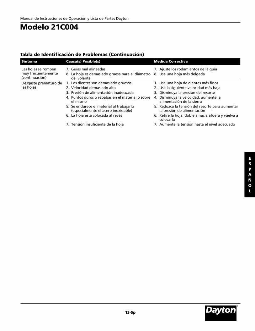
Modelo 21C004
13-Sp
Las hojas se rompenmuy frecuentemente(continuación)Desgaste prematuro delas hojas
Tabla de Identificación de Problemas (Continuación)Síntoma Causa(s) Posible(s) Medida Correctiva
7. Guías mal alineadas8. La hoja es demasiado gruesa para el diámetro
del volante 1. Los dientes son demasiado gruesos 2. Velocidad demasiado alta 3. Presión de alimentación inadecuada 4. Puntos duros o rebabas en el material o sobre
el mismo 5. Se endurece el material al trabajarlo
(especialmente el acero inoxidable) 6. La hoja está colocada al revés
7. Tensión insuficiente de la hoja
7. Ajuste los rodamientos de la guía 8. Use una hoja más delgada
1. Use una hoja de dientes más finos 2. Use la siguiente velocidad más baja 3. Disminuya la presión del resorte 4. Disminuya la velocidad, aumente la
alimentación de la sierra 5. Reduzca la tensión del resorte para aumentar
la presión de alimentación 6. Retire la hoja, dóblela hacia afuera y vuelva a
colocarla 7. Aumente la tensión hasta el nivel adecuado
ESPAÑOL
Manual de Instrucciones de Operación y Lista de Partes Dayton
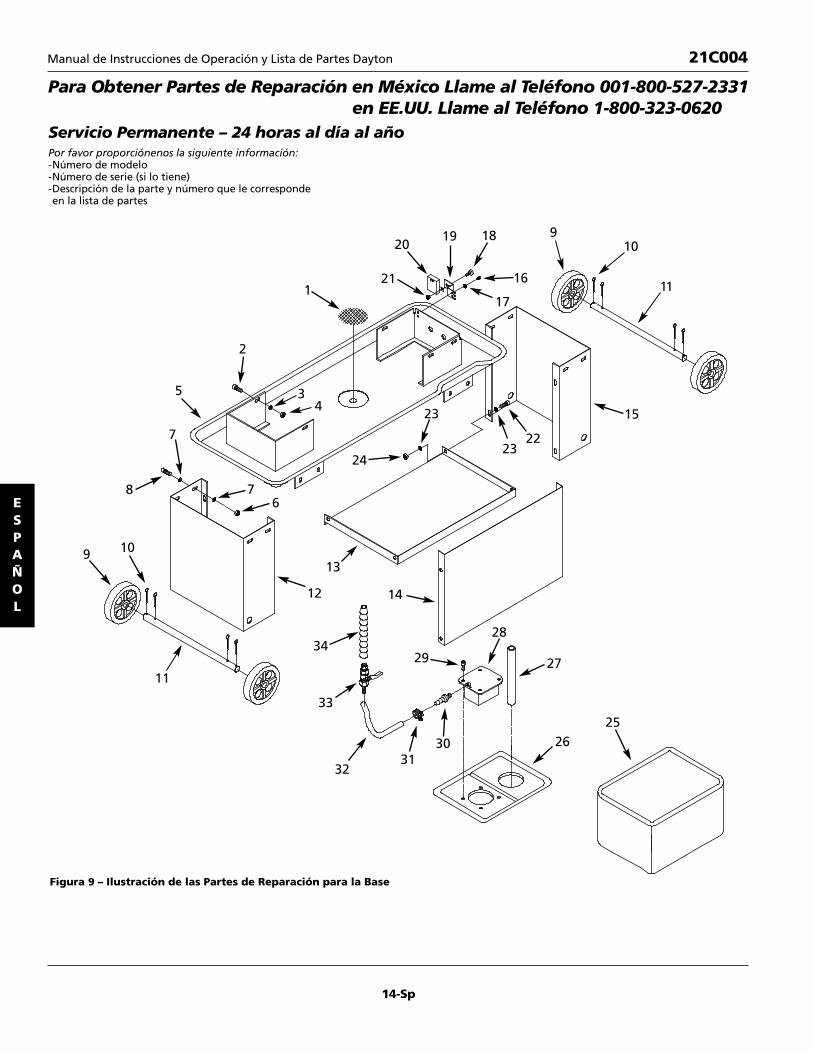
14-Sp
Figura 9 – Ilustración de las Partes de Reparación para la Base
ESPAÑOL
Para Obtener Partes de Reparación en México Llame al Teléfono 001-800-527-2331en EE.UU. Llame al Teléfono 1-800-323-0620
Servicio Permanente – 24 horas al día al añoPor favor proporciónenos la siguiente información:-Número de modelo-Número de serie (si lo tiene)-Descripción de la parte y número que le corresponde en la lista de partes
Manual de Instrucciones de Operación y Lista de Partes Dayton 21C004
11
109
8
24
23
2322
15
7
19 18
16
910
1117
20
211
2
435
76
12
34
14
13
33
3231
30
29
28
27
2625

15-Sp
1 Filtro 36360.00 12 Perno de cabeza hexagonal, * 8
5/16-18 x 1-1/4”3 Arandela plana, 5/16” * 84 Tuerca hexagonal, 5/16-18 * 85 Bandeja para recoger virutas † 16 Tuerca hexagonal, 3/8-16 * 87 Arandela plana, 3/8” * 168 Perno de cabeza hexagonal, * 8
3/8-16 x 1”9 Rueda 36361.00 4
10 Chaveta 36362.00 811 Eje 36363.00 212 Pata izquierda † 113 Anaquel 36364.00 114 Panel † 115 Pata derecha † 116 Tornillo de cabeza de placa, * 2
1/4-20 x 1/2”17 Arandela plana, 1/4” * 2
18 Tornillo de cabeza de placa, * 11/4-20 x 3/4”
19 Soporte 36365.00 120 Interruptor 36366.00 121 Tuerca hexagonal, 1/4-20 * 122 Perno de cabeza hexagonal, * 4
5/16-18 x 5/8”23 Arandela plana, 5/16” * 824 Tuerca hexagonal, 5/16-18 * 425 Deposito de liquido enfriador 36367.00 126 Cubierta 36368.00 127 Manguera 36369.00 128 Bomba 36370.00 129 Perno de cabeza hexagonal, * 4
5/16-18 x 1”30 Accesorio de manguera 36371.00 131 Abrazadera de manguera 36372.00 232 Manguera 36373.00 133 Vavula 36374.00 134 Asamblea de boca 36375.00 1
No. de No. de Ref. Descripción Parte Cant.
No. de No. de Ref. Descripción Parte Cant.
(*) Artículos de ferretería estándar disponibles localmente.
ESPAÑOL
Lista de Partes de Reparación para la Base
21C004Manual de Instrucciones de Operación y Lista de Partes Dayton

16-Sp
ESPAÑOL
Figura 10 – Ilustración de las Partes de Reparación para la Soporte
Para Obtener Partes de Reparación en México Llame al Teléfono 001-800-527-2331en EE.UU. Llame al Teléfono 1-800-323-0620
Servicio Permanente – 24 horas al día al añoPor favor proporciónenos la siguiente información:-Número de modelo-Número de serie (si lo tiene)-Descripción de la parte y número que le corresponde en la lista de partes
Manual de Instrucciones de Operación y Lista de Partes Dayton 21C004
32
13
30
31
21
39
38
37
35
34
33
336
21
12
29
17
21
41
40 12
28
27
26
24
2
3
25
17
16
2
23
1
2221
20
19
18
62
1
543
4
84
10
7
9
11
14
15
48

17-Sp
Lista de Partes de Reparación para la Soporte
1 Perno de cabeza hexagonal, * 65/16-18 x 5/8”
2 Arandela plana, 5/16” * 63 Tuerca hexagonal, 3/8-16 * 34 Arandela plana, 3/8” * 55 Soporte de resorte 36052.00 16 Argolla 36053.00 17 Resorte 36054.00 18 Perno de cabeza hexagonal, * 3
3/8-16 x 1-1/4”9 Mordaza de prensa izquierda 36055.00 1
10 Perno de cabeza hexagonal, * 110-1.5 x 40mm
11 Mordaza de prensa derecha 36056.00 112 Perno de cabeza hexagonal, * 1
1/2-13 x 2-1/2”13 Tornillo decarroceria, * 1
1/2-13 x 2-1/2”14 Arandela plana, 1/2” * 115 Tuerca hexagonal, 1/2-13 * 116 Pieza de soporte del pivote 36057.00 117 Tornillo de fijación, 5/16-18 x 3/8” * 218 Placa 36058.00 119 Arandela plana, 1/4” * 120 Perno de cabeza hexagonal, * 1
1/4-20 x 1/2”
21 Tuerca hexagonal, 5/16-18 * 222 Perno de cabeza hexagonal, * 1
5/16-18 x 1” 23Perno decabeza hexagonal, * 1
3/8-16 x 2”24 Anclaje de conexión 36059.00 325 Placa 36060.00 126 Eje 36061.00 127 Buje 36062.00 128 Soporte 36063.00 129 Tope de seguridad 36064.00 130 Varilla de tope de seguridad 36065.00 131 Arandela de seguridad, 5/16” * 232 Soporte † 133 Tornillo de fijación, 5/16-18 x 1/2” * 134 Volante manual 36066.00 135 Tope 36067.00 136 Placa de soporte 36068.00 137 Arandela plana, 5/8” * 138 Tornillo de entrada 36069.00 139 Tuerca de entrada 36070.00 140 Soporte 36317.00 141 Conjunto del cilindro hidráulico 36318.00 1
No. de No. de Ref. Descripción Parte Cant.
No. de No. de Ref. Descripción Parte Cant.
(*) Artículos de ferretería estándar disponibles localmente.(†) No se encuentra disponible como porte de reparación.
ESPAÑOL
21C004Manual de Instrucciones de Operación y Lista de Partes Dayton

18-Sp
ESPAÑOL
Figura 11 – Ilustración de las Partes de Reparación para el Cabezal
Para Obtener Partes de Reparacion en México Llame al Teléfono 001-800-527-2331en EE.UU. Llame al Teléfono 1-800-323-0620
Servicio Permanente – 24 horas al día al añoPor favor proporciónenos la siguiente información:-Número de modelo-Número de serie (si lo tiene)-Descripción de la parte y número que le corresponde en la lista de partes
Manual de Instrucciones de Operación y Lista de Partes Dayton 21C004
23
10
44
2220
94
2145
19
18
50
49
48
6
2
1
47
46
87
53
4
910
11
12
1113
14
1716
15
910 30
2928
35
24
25
2627
9
33
19
32
3110
38
37
36
41
3534 43
25
43
4240
35
39

19-Sp
Lista de Partes de Reparación para el Cabezal
1 Manilla 36091.00 22 Cubierta de hoja 36092.00 13 Arandela plana, 1/4” * 64 Tornillo de cabeza redonda, * 6
1/4-20 x 1/2”5 Cubierta de volante impulsor 36093.00 16 Hoja 36094.00 17 Anillo de retención 36095.00 18 Volante impulsor 36096.009 Perno de cabeza hexagonal, * 6
5/16-18 x 5/8”10 Arandela plana, 5/16” * 711 Rodamiento 6200zz 07062.00 212 Volante de alineación 36097.00 113 Anillo de retención 3BMI-35 07370.00 114 Buje 36098.00 215 Manilla 36099.00 116 Espaciador 36316.00 117 Resorte 36100.00 118 Soporte de envío 36101.00 119 Placa guia 36102.00 220 Eje de volante de alineación 36103.00 121 Espiga, 4 x 25mm 36104.00 122 Bloque de tensión 36105.00 123 Perno de cabeza hueca, * 3
5/16-18 x 1-3/4”24 Barra guia izquierda 36106.00 125 Manilla 36107.00 226 Protección de la hoja 36108.00 127 Tornillo de cabeza redonda, * 2
#10-24 x 1/4”
28 Soporte izquierdo 36109.00 129 Arandela de seguridad, 3/8” * 430 Tuerca hexagonal, 3/8-24 * 431 Arandela de seguridad, 5/16” * 232 Perno de cabeza hueca, * 2
5/16-18 x 1-1/4”33 Pasador 36110.00 234 Barra guia derecha 36111.00 135 Rodamiento 6000zz 04018.00 236 Placa 36112.00 137 Tornillo de cabeza troncoconica, * 2
1/4-20 x 1/2”38 Eje de rodamientos 36113.00 239 Anillo de retención 3AMI-10 00221.00 440 Rodamiento 6000zz 04018.00 841 Eje excentrico 36114.00 242 Soporte izquierdo 36115.00 143 Escobilla 36116.00 144 Perno de cabeza hexagonal, * 3
5/16-18 x 1”45 Soporte 36117.00 146 Soporte 36118.00 147 Perno de cabeza hexagonal, * 3
#8-32 x 3/8”48 Cubierta de rodamiento 36119.00 149 Caja del interruptor 36120.00 150 Interruptor 36121.00 151 Interruptor de bomba 36122.00 1
No. de No. de Ref. Descripción Parte Cant.
No. de No. de Ref. Descripción Parte Cant.
(*) Artículos de ferretería estándar disponibles localmente.
ESPAÑOL
21C004Manual de Instrucciones de Operación y Lista de Partes Dayton

20-Sp
ESPAÑOL
Para Obtener Partes de Reparación en México Llame al Teléfono 001-800-527-2331en EE.UU. Llame al Teléfono 1-800-323-0620
Servicio Permanente – 24 horas al día al añoPor favor proporciónenos la siguiente información:-Número de modelo-Número de serie (si lo tiene)-Descripción de la parte y número que le corresponde en la lista de partes
Figura 12 – Ilustración de las Partes de Reparación para la Caja de Engranajes
Manual de Instrucciones de Operación y Lista de Partes Dayton 21C004
4
5
30
39
40
37
27
10
21
2425
22 23
3313
3436
38
3532
31
3
2
7
3
6
1
8
2627
2826
29
13
12
1819
15
20
14
9
10
11
17
8
16

1 Correa V, A-650 36071.00 12 Polea del motor 36072.00 13 Tornillo de fijación, 1/4-20 x 3/8” * 44 Caja de la polea 36073.00 15 Tornillo con arandela 36074.00 16 Polea manejada 36075.00 17 Tornillo de cabeza de placa, * 3
1/4-20 x 1/2”8 Arandela plana, 1/4” * 59 Anillo de retención 3AMI-17 00341.00 1
10 Rodamiento 6003z 05092.00 211 Tornillo de fijación, 5/16-18 x 3/8” * 112 Buje 36076.00 113 Rodamiento 6003zz 04838.00 114 Perno de cabeza hexagonal, * 4
3/8-16 x 1-1/4”15 Arandela de seguridad, 3/8” * 416 Tornillo de cabeza redonda, * 2
1/4-20 x 1/2”17 Cubierta 36077.00 118 Cuña, 5 x 5 x 55mm 15781.00 119 Eje de tornillo sin fin 36078.00 120 Caja de engranajes 121 Pieza de soporte de 36079.00 1
montaje del motor22 Perno de cabeza hexagonal, * 1
1/4-20 x 1”23 Tuerca hexagonal, 1/4-20 * 124 Arandela plana, 5/16” * 425 Perno de cabeza hexagonal, * 4
5/16-18 x 1/2”
26 Tuerca hexagonal, 3/8-16 * 427 Arandela plana, 3/8” * 828 Placa de montaje del motor 36080.00 129 Perno de cabeza hexagonal, * 1
3/8-16 x 2-1/4”30 Cuña, 5 x 5 x 40mm 07885.00 131 Motor 36081.00 132 Perno de cabeza hexagonal, * 4
3/8-16 x 1”33 Buje 36082.00 134 Buje 36083.00 135 Cuna, 5 x 5 x 20mm 00537.00 136 Asamblea de gearshaft 36084.00 137 Empaquetadura 36085.00 138 Cubierta de caja de engranajes 36086.00 139 Perno de respiracion 36087.00 140 Perno de cabeza hexagonal, * 4
1/4-20 x 5/8”∆� Conjunto de la caja de engranajes 36088.00 1Accesorios recomendados∆� Plataforma de soporte 6Z765 1∆� Lámpara con base magnética 4PD35 1∆� 1 litros de fluido de corte 4KYP3 1∆� 1 litros de aceite industrial 4ZF30 1
para engranajes∆� Elemento bimetálico de 5-8 GPC 4WE14 1∆� Elemento bimetálico de 6-10 GPC 4WE15 1∆� Elemento bimetálico de 10-14 GPC 4WE13 1
21-Sp
Lista de Partes de Reparación para la Caja de Engranajes
ESPAÑOL
No. de No. de Ref. Descripción Parte Cant.
No. de No. de Ref. Descripción Parte Cant.
(*) Artículos de ferretería estándar disponibles localmente.(∆) No se muestra.(†) No se encuentra disponible como porte de reparación.
21C004Manual de Instrucciones de Operación y Lista de Partes Dayton

Sierra de Banda de 18 x 30 cm paraCortar Metales Dayton®
Fabricado para Dayton Electric Mfg. Co.Lake Forest, Illinois 60045 EE.UU.
Manual de Instrucciones de Operación y Lista de Partes Dayton 21C004
GARANTIA LIMITADA
GARANTIA LIMITADA DE DAYTON POR UN AÑO. DAYTON ELECTRIC MFG. CO. (DAYTON) LE GARANTIZA AL USUARIOORIGINAL QUE EL MODELO TRATADO EN ESTE MANUAL DE LA SIERRA DE BANDA DE 18 x 30 CM PARA CORTAR METALESDAYTON® ESTA LIBRE DE DEFECTOS DE MANO DE OBRA O DE MATERIAL, SI SE LE SOMETE A USO NORMAL, DURANTE UNAÑO A PARTIR DE LA FECHA DE COMPRA. CUALQUIER PARTE QUE SE HALLE DEFECTUOSA, YA SEA EN EL MATERIAL O EN LA MANO DE OBRA, Y SEA DEVUELTA (CON LOS COSTOS DE ENVIO PAGADOS POR ADELANTADO) A UN CENTRO DE SERVICIOAUTORIZADO DESIGNADO POR DAYTON, SERA REPARADA O REEMPLAZADA (NO EXISTE OTRA POSIBILIDAD) SEGUN LODETERMINE DAYTON. PARA OBTENER INFORMACION SOBRE LOS PROCEDIMIENTOS DE RECLAMO CUBIERTOS EN LA GARANTIA LIMITADA, VEA LA SECCION “ATENCION OPORTUNA” QUE APARECE MAS ADELANTE. ESTA GARANTIA LIMITADACONFIERE AL COMPRADOR DERECHOS LEGALES ESPECIFICOS QUE VARIAN DE JURISDICCION A JURISDICCION.
LIMITES DE RESPONSABILIDAD. EN LA MEDIDA EN QUE LAS LEYES APLICABLES LO PERMITAN, LA RESPONSABILIDAD DE DAYTON POR LOS DAÑOS EMERGENTES O INCIDENTALES ESTA EXPRESAMENTE EXCLUIDA. LA RESPONSABILIDAD DE DAYTON EXPRESAMENTE ESTA LIMITADA Y NO PUEDE EXCEDER EL PRECIO DE COMPRA PAGADO POR EL ARTICULO.
EXCLUSION DE RESPONSABILIDAD DE LA GARANTIA. SE HAN HECHO ESFUERZOS DILIGENTES PARA PROPORCIONARINFORMACION E ILUSTRACIONES APROPIADAS SOBRE EL PRODUCTO EN ESTE MANUAL; SIN EMBARGO, ESTA INFORMACION Y LAS ILUSTRACIONES TIENEN COMO UNICO PROPOSITO LA IDENTIFICACION DEL PRODUCTO Y NO EXPRESAN NI IMPLICANGARANTIA DE QUE LOS PRODUCTOS SEAN VENDIBLES O ADECUADOS PARA UN PROPOSITO EN PARTICULAR NI QUE SE AJUS-TAN NECESARIAMENTE A LAS ILUSTRACIONES O DESCRIPCIONES. CON EXCEPCION DE LO QUE SE ESTABLECE A CONTINUA-CION, DAYTON NO HACE NI AUTORIZA NINGUNA GARANTIA O AFIRMACION DE HECHO, EXPRESA O IMPLICITA, QUE NO SEAESTIPULADA EN LA “GARANTIA LIMITADA” ANTERIOR.
Consejo Técnico y Recomendaciones, Exclusiones de Responsabilidad. A pesar de las prácticas, negociaciones o usoscomerciales realizados previamente, las ventas no deberán incluir el suministro de consejo técnico o asistencia o diseño del sis-tema. Dayton no asume ninguna obligación o responsabilidad por recomendaciones, opiniones o consejos no autorizadossobre la elección, instalación o uso de los productos.
Adaptación del Producto. Muchas jurisdicciones tienen códigos o regulaciones que rigen la venta, la construcción, la insta-lación y/o el uso de productos para ciertos propósitos que pueden variar con respecto a los aplicables a las zonas vecinas. Si bien se trata de que los productos Dayton cumplan con dichos códigos, no se puede garantizar su conformidad y no sepuede hacer responsable por la forma en que se instale o use su producto. Antes de comprar y usar el producto, revise su aplicación y todos los códigos y regulaciones nacionales y locales aplicables y asegúrese de que el producto, la instalación y el uso los cumplan.
Ciertos aspectos de limitación de responsabilidad no se aplican a productos al consumidor; es decir (a) algunas jurisdicciones nopermiten la exclusión ni limitación de daños incidentales o consecuentes, de modo que las limitaciones o exclusiones anterioresquizás no apliquen en su caso; (b) asimismo, algunas jurisdicciones no permiten limitar el plazo de una garantía implícita, porlo tanto, la limitación anterior quizás no aplique en su caso; y (c) por ley, mientras la Garantía Limitada esté vigente no podránexcluirse ni limitarse en modo alguno ninguna garantía implícita de comercialización o de idoneidad para un propósito en particular aplicables a los productos al consumidor adquiridos por éste.
Atención Oportuna. Se hará un esfuerzo de buena fe para corregir puntualmente, o hacer otros ajustes, con respecto acualquier producto que resulte defectuoso dentro de los términos de esta garantía limitada. En el caso de que encuentre un producto defectuoso y que esté cubierto dentro de los límites de esta garantía haga el favor de escribir primero, o llame, al distribuidor a quien le compró el producto. El distribuidor le dará las instrucciones adicionales. Si no puede resolver el problema en forma satisfactoria, escriba a Dayton a la dirección a continuación, dando el nombre del distribuidor, su dirección,la fecha y el número de la factura del distribuidor y describa la naturaleza del defecto. La propiedad del artículo y el riesgo de pérdida pasan al comprador en el momento de la entrega del artículo a la compañía de transporte. Si el producto se daña durante el transporte, debe presentar su reclamo a la compañía transportista.
Fabricado para Dayton Electric Mfg. Co., 100 Grainger Parkway, Lake Forest, Illinois 60045 EE.UU.
ESPAÑOL