property damage! Retain instructions for future … Heaters/101421-01.pdf · Dayton Portable...
24
Operating Instructions & Parts Manual Dayton Portable Oil-Fired Heaters ® Form 5S1792 Please read and save these instructions. Read carefully before attempting to assemble, install, operate or maintain the product described. Protect yourself and others by observing all safety information. Failure to comply with instructions could result in personal injury and/or property damage! Retain instructions for future reference. Unpacking 1. Remove all packing items supplied with heater for shipment. 2. Remove all items from carton. 3. Check heater for any shipping damage. If heater is damaged, promptly inform dealer where you bought heater. 2E510D, 2E511D, 3E218D, and 3E219C Version B - For Reduction G016.J ® Figure 1 – Models 2E510D and 2E511D Figure 2 – Models 3E218D and 3E219C ARL LOGO G 004 ® Description The Dayton models 2E510D, 2E511D, 3E218D, and 3E219C heaters are 30,000 to 150,000 Btu/Hr heaters. These heaters use Kerosene #1 fuel oil for combustion and electricity to run the motor. They are primarily intended for indoor and outdoor temporary heating of buildings under construction, alteration, or repair. They may be used in agricultural, industrial, and commercial environments. Output Fuel Tank Capacity Fuel Consumption Model Rating Btu Fuel (U.S. Gallons) (U.S. Gallons/Hr.) Motor RPM 2E510D 35,000 Kerosene or No. 1 fuel oil 3.0 0.3 1725 2E511D 55,000 Kerosene or No. 1 fuel oil 5.0 0.4 1725 3E218D 110,000 Kerosene or No. 1 fuel oil 9.0 0.8 3450 3E219C 150,000 Kerosene or No. 1 fuel oil 13.5 1.1 3450 Hot Air Air Pump Shipping Weight Heater Weight Spark Plug Gap Model Output (CFM) Pressure (PSI) (Pounds) (Pounds - without fuel) (Inches) 2E510D 165 3.0 38 35 .055 2E511D 175 3.4 39 36 .075 3E218D 490 4.5 65 55 .075 3E219C 500 5.0 65 55 .075 GENERAL SPECIFICATIONS © 1995 W.W. Grainger, Inc. Printed in U.S.A. 03430 0895/206/VCPVP
Transcript of property damage! Retain instructions for future … Heaters/101421-01.pdf · Dayton Portable...

Operating Instructions & Parts Manual
Dayton PortableOil-Fired Heaters
®
Form 5S1792
Please read and save these instructions. Read carefully before attempting to assemble, install, operate or maintain the product described.Protect yourself and others by observing all safety information. Failure to comply with instructions could result in personal injury and/orproperty damage! Retain instructions for future reference.
Unpacking1. Remove all packing items supplied
with heater for shipment.
2. Remove all items from carton.
3. Check heater for any shippingdamage. If heater is damaged,promptly inform dealer where youbought heater.
2E510D, 2E511D, 3E218D, and 3E219C
Version B - For Reduction G016.J
®
Figure 1 – Models 2E510D and 2E511D Figure 2 – Models 3E218D and 3E219CARL LOGO G 004
®
DescriptionThe Dayton models 2E510D, 2E511D, 3E218D, and 3E219C heaters are 30,000 to150,000 Btu/Hr heaters. These heaters use Kerosene #1 fuel oil for combustionand electricity to run the motor. They are primarily intended for indoor andoutdoor temporary heating of buildings under construction, alteration, or repair.They may be used in agricultural, industrial, and commercial environments.
Output Fuel Tank Capacity Fuel ConsumptionModel Rating Btu Fuel (U.S. Gallons) (U.S. Gallons/Hr.) Motor RPM2E510D 35,000 Kerosene or No. 1 fuel oil 3.0 0.3 17252E511D 55,000 Kerosene or No. 1 fuel oil 5.0 0.4 17253E218D 110,000 Kerosene or No. 1 fuel oil 9.0 0.8 34503E219C 150,000 Kerosene or No. 1 fuel oil 13.5 1.1 3450
Hot Air Air Pump Shipping Weight Heater Weight Spark Plug GapModel Output (CFM) Pressure (PSI) (Pounds) (Pounds - without fuel) (Inches)2E510D 165 3.0 38 35 .0552E511D 175 3.4 39 36 .0753E218D 490 4.5 65 55 .0753E219C 500 5.0 65 55 .075
GENERAL SPECIFICATIONS
© 1995 W.W. Grainger, Inc.Printed in U.S.A.034300895/206/VCPVP

Dayton Operating Instructions and Parts Manual
2
Dayton PortableOil-Fired Heaters
®
101421
AmperageModel Electrical Input (during normal run)2E510D 120 Volt/60 Hertz 2.02E511D 120 Volt/60 Hertz 2.03E218D 120 Volt/60 Hertz 4.53E219C 120 Volt/60 Hertz 4.5
ELECTRICAL SPECIFICATIONS
Product Identification
Figure 4 – Models 3E218D and 3E219C
Power Cord
FuelCap
Fan Guard
Figure 3 – Models 2E510D and 2E511D
Hot Air Outlet
Flame-Out ControlReset Button
FanGuard
FuelTank
Fuel Cap
Power Cord
Side Cover
FuelTank
Air FilterEnd Cover
Side Cover
Lower Shell
Upper Shell
Flame-Out ControlReset Button
LowerShell
Hot AirOutlet
Handle
Upper Shell

3
Models 2E510D, 2E511D, 3E218D, and 3E219C
Dayton Operating Instructions and Parts Manual
101421®
General Safety InformationMake certain you read and understandall warnings. Keep these instructions forreference. They are your guide to safeand proper operation of this heater.
Safety information appears throughoutthese instructions. Pay close attention tothem. Below are definitions for the safetyinformation listed throughout this manual.
Under this heading,installation, operat-
ing and maintenance procedures orpractices will be found that, if notcarefully followed, WILL result in IMME-DIATE serious personal injury or death.
Under this head-ing, installation,
operating, and maintenance proce-dures or practices will be found that, ifnot carefully followed, COULD result insevere personal injury or death.
Under this heading,installation, operat-
ing, and maintenance procedures orpractices will be found that, if not carefullyfollowed, COULD result in minor personalinjury, product or property damage.
Carbon monoxidepoisoning may lead
to death! Carbon monoxide poisoning:Some people are more affected bycarbon monoxide than others. Earlysigns of carbon monoxide poisoningresemble the flu, with headaches,dizziness, and/or nausea. If you havethese signs, the heater may not beworking properly. Get fresh air atonce! Have heater serviced.
IMPORTANT: Every possible circumstancethat might involve a hazard cannot beanticipated. The warnings in this manualand on tags or decals affixed to the unitare therefore not all-inclusive. If aprocedure, work method, or operatingtechnique not specifically recommendedby Dayton is used, you must make sure itis safe for you and others. You shouldalso ensure that equipment will not bedamaged or made unsafe by the operat-ing or maintenance method you choose.
• Use only kero-sene or No. 1 fuel
oil to avoid risk of fire or explosion.Never use gasoline, naphtha, paintthinners, alcohol, or other highlyflammable fuels.
• Fueling
a) Personnel involved with fuelingshall be qualified and thoroughlyfamiliar with the manufacturer'sinstructions and applicable federal,state, and local regulations regard-ing the safe fueling of heating units.
b) Only the type of fuel specified onthe heater's data plate shall be used.
c) All flame, including the pilotlight, if any, shall be extinguishedand the heater allowed to cool, priorto fueling.
Improper use ofthis heater can
cause serious injury or death fromburns, fire, explosion, electrical shock,and carbon monoxide poisoning.
Make certain you read and understandall warnings. Keep these instructionsfor reference. They are your guide tosafe and proper operation of thisheater.
d) During fueling, all fuel lines andfuel-line connections shall beinspected for leaks. Any leaks shallbe repaired prior to returning theheater to service.
e) At no time shall more than oneday's supply of heater fuel be storedinside a building in the vicinity ofthe heater. Bulk fuel storage shall beoutside the structure.
f) All fuel storage shall be located aminimum of 25 feet from heaters,torches, welding equipment, andsimilar sources of ignition (excep-tion: the fuel reservoir integral withthe heater unit).
g) Whenever possible, fuel storageshall be confined to areas wherefloor penetrations do not permit fuelto drip onto or be ignited by a fire atlower elevation.
h) Fuel storage shall be in accor-dance with the federal, state, orlocal authority having jurisdiction.
• Never use heater where gasoline,paint thinner, or other highlyflammable vapors are present.
• Follow all local ordinances and codeswhen using heater.
• Use only in well-vented areas. Provideat least three square feet of fresh,outside air for each 100,000 BTU/Hr ofrating. This heater produces carbonmonoxide, which is listed by theState of California as a reproductivetoxin under Proposition 65.
• Use only in places free of flammablevapors or high dust content.
• Use only with the electrical voltageand frequency specified on modelplate.
• Use only a three-prong, groundedextension cord.

Dayton Operating Instructions and Parts Manual
4
Dayton PortableOil-Fired Heaters
®
101421
General Safety Information(Continued)
Figure 5 - Cross Section Operational View
CleanHeatedAir Out
Air For FuelSystem
Air For Combus-tion and Heating Fuel
FuelFilter
Air LineTo Burner
ElectronicIgnitor
AirOutputFilter
CoolAir In
Air IntakeFilter
Air Pump
Fan
Motor
CombustionChamber
SparkPlug
FuelTank Nozzle
BurnerHead
THEORY OF OPERATION
THE FUEL SYSTEM: The air pumpforces air through the air line. The airis then pushed through the burnerhead nozzle. This air causes fuel tolift from the tank. A fine mist of fuelis sprayed into the combustionchamber.
THE AIR SYSTEM: The motor turns thefan. The fan pushes air into andaround the combustion chamber. Thisair is heated and provides a stream ofclean, hot air.
THE IGNITION SYSTEM: The electronicignitor sends voltage to the sparkplug. The spark plug ignites the fueland air mixture.
THE FLAME-OUT CONTROL SYSTEM:This system causes the heater to shutdown if the flame goes out.
FUELS
Use only keroseneor No. 1 fuel oil to
avoid risk of fire or explosion. Neveruse gasoline, naphtha, paint thinners,alcohol, or other highly flammablefuels.
Do not use heavy fuels such as No. 2fuel oil or No. 2 Diesel. Using heavyfuels will result in:
• clogged fuel filter and nozzle
• carbon build-up on spark plug
• the need of non-toxic anti-icer infuel during very cold weather
IMPORTANT: Use a KEROSENE ONLYcontainer. Be sure storage container isclean. Foreign matter such as rust, dirt, orwater will cause the flame-out control toshut down heater. Foreign matter may alsorequire you to clean fuel system often.
• Heaters used in the vicinity oftarpaulins, canvas, or similar enclo-sure materials shall be located a safedistance from such materials. Therecommended minimum safe dis-tance is 10 feet. It is further recom-mended that these enclosurematerials be of a fire retardantnature. These enclosure materialsshall be securely fastened to preventthem from igniting or from upsettingthe heater due to wind action.
• Minimum heater clearances fromcombustibles:
Outlet: 8 Ft. Sides: 4 Ft.
Top: 4 Ft. Rear: 4 Ft.
• Locate heater on a stable and levelsurface while hot or running or a firemay occur.
• When moving or storing heater, keepheater in a level position or fuelspillage may occur.
• Keep children and animals awayfrom heater.
• Unplug heater when not in use.
• When used with thermostat, heatermay start anytime.
• Never use heater in living or sleep-ing areas.
• Never block air inlet (rear) or airoutlet (front) of heater.
• Never move, handle, refuel, orservice a hot, operating, or plugged-in heater.
• Never attach duct work to front orrear of heater.

5
Models 2E510D, 2E511D, 3E218D, and 3E219C
Dayton Operating Instructions and Parts Manual
101421®
ASSEMBLY(For Models 3E218D and 3E219C Only)
These models are furnished withwheels and handles. Wheels, handles,and the mounting hardware are foundin the shipping carton.
TOOLS NEEDED
• Medium Phillips Screwdriver
• 3/8" Open or Adjustable Wrench
• Hammer
1. Slide axle through wheel supportframe. Install wheels on axle.
Figure 6 - Wheel and Handle Assembly,Models 3E218D and 3E219C Only
IMPORTANT: When installing wheels,point extended hub of wheels towardwheel support frame (see Figure 6).
2. Place cap nuts on axle ends. Gentlytap with hammer to secure.
3. Place heater on wheel supportframe. Make sure air inlet end (rear)of heater is over wheels. Line upholes on fuel tank flange with holeson wheel support frame.
4. Place front handle and rear handle ontop of fuel tank flange. Insert screwsthrough handles, fuel tank flange,and wheel support frame. Attach nutfinger tight after inserting each screw.
5. After inserting all screws, tightennuts firmly.
VENTILATION
Follow the mini-mum fresh, outside
air ventilation requirements. If properfresh, outside air ventilation is notprovided, carbon monoxide poisoningcan occur. Provide proper fresh,outside air ventilation before runningheater.
Provide a fresh air opening of at leastthree square feet for each 100,000Btu/Hr rating. Provide extra fresh air ifmore heaters are being used.
Example: A 150,000 Btu/Hr heaterrequires one of the following:
• a two-car garage door raised sixinches
• a single-car garage door raisednine inches
• two, thirty-inch windows raisedtwelve inches
Screw
ExtendedHub
Axle
Nut
Hot AirOutlet
AirInlet
Cap Nut
Front Handle
Rear Handle
Review andunderstand the
warnings in the Safety InformationSection. They are needed to safelyoperate this heater. Follow all localcodes when using this heater.
Operation
TO START HEATER
1. Follow all ventilation and safetyinformation.
2. Fill fuel tank with kerosene or No. 1fuel oil.
3. Attach fuel cap.
4. Plug power cord of heater intothree-prong, grounded extensioncord. Extension cord must be at leastsix feet long.
EXTENSION CORD WIRE SIZEREQUIREMENTS
• 6 to 10 feet long, use 18 AWGrated cord.
• 11 to 100 feet long, use 16 AWGrated cord.
• 101 to 200 feet long, use 14 AWGrated cord.
Figure 7 - Flame-out Control ResetButton, Models 2E510D and 2E511D
FuelTankFlange
Wheel SupportFrame
Wheel
Flame-out ControlReset Button
General Safety Information(Continued)

Dayton Operating Instructions and Parts Manual
6
Dayton PortableOil-Fired Heaters
®
101421
Figure 8 - Flame-out Control ResetButton, Models 3E218D and 3E219C
Operation (Continued)
5. Plug extension cord into standard 120volt/60 hertz, three-hole, groundedoutlet. Heater will start whenextension cord is plugged into outlet.If not, push in flame-out control resetbutton (see Figures 7 and 8).
TO STOP HEATER
1. Unplug extension cord from outlet.
TO RESTART HEATER
1. Wait 2 minutes after stopping heater.
2. Repeat steps under To Start Heater.
NOTE: For automatic operation, useModel 2E535 or Model 2E817 thermo-stat (see Accessories, page 20).
Never serviceheater while it is
plugged in, operating, or hot. Severeburns and electrical shock can occur.
Maintenance
UPPER SHELL REMOVAL
1. Remove screws along each side ofheater using 5/16" nut-driver. Thesescrews attach upper and lower shellstogether (see Figures 9 and 10).
2. Lift upper shell off.
3. Remove fan guard.
Upper Shell
Fan Guard
Figure 9 - Upper Shell Removal, Models2E510D and 2E511D
FanGuard
Figure 10 - Upper Shell Removal,Models 3E218D and 3E219C
FAN
IMPORTANT: Remove fan from motorshaft before removing motor fromheater. The weight of the motor restingon the fan could damage the fan pitch.
1. Remove upper shell.
2. Use 1/8" Allen wrench to loosensetscrew which holds fan to motorshaft.
3. Slip fan off motor shaft.
4. Clean fan using a soft cloth moist-ened with kerosene or solvent.
5. Dry fan thoroughly.
6. (Models 2E510D, 2E511D, and3E218D) Replace fan on motor shaft.Place fan hub flush with end ofmotor shaft (see Figure 11).
(Model 3E219C) Replace fan onmotor shaft. Make sure set screw istouching back of flat surface onmotor shaft (see Figure 12, page 7).
7. Place setscrew on flat of shaft. Tightensetscrew firmly (40-50 inch-pounds).
8. Replace fan guard and upper shell.
Figure 11 - Fan Cross Section, Models2E510D, 2E511D, and 3E218D
Motor
Flush
Flame-outControl ResetButton
UpperShell
MotorShaft
Setscrew
Fan

7
Models 2E510D, 2E511D, 3E218D, and 3E219C
Dayton Operating Instructions and Parts Manual
101421®
Figure 12 - Fan Cross Section, Model3E219C
AIR OUTPUT, AIR INTAKE, AND LINTFILTERS
1. Remove upper shell (see Figure 10).
2. Remove filter end cover screws using5/16" nut-driver.
3. Remove filter end cover.
4. Replace air output and lint filters.
5. Wash and dry with soap and wateror replace air intake filter.
6. Replace filter end cover.
7. Replace fan guard and upper shell.
IMPORTANT: Do not oil filters.
Maintenance (Continued)
Lint Filter
Air Output Filter
Fan
Motor
5. Remove pressure gauge. Replacepressure gauge plug in filter end cover.
Figure 14 - Air Output, Air Intake, andLint Filters, Models 3E218D and 3E219C
Air OutputFilter
LintFilter
Fan Guard
Air Intake Filter
Filter End Cover
Pump Model Pressure
2E510D 3.0 PSI2E511D 3.4 PSI3E218D 4.5 PSI3E219C 5.0 PSI
Figure 15 - Pressure Gauge PlugRemoval
PressureGauge Plug Relief
Valve
PRESSURE ADJUST P
PressureGauge
Figure 16 - Adjusting Pump Pressure
FUEL FILTER
1. Remove side cover screws using5/16" nut-driver.
2. Remove side cover.
3. Pull upper fuel line off fuel filterneck (see Figure 17, page 8).
4. Carefully pry bushing, fuel filter, andlower fuel line (Models 3E218D and3E219C only) out of fuel tank (seeFigure 18, page 8).
Figure 13 - Air Output, Air Intake, andLint Filters, Models 2E510D and 2E511D
SetscrewMotorShaft
Air Intake FilterFilter End Cover
Fan Guard
PUMP PRESSURE ADJUSTMENT
1. Remove pressure gauge plug fromfilter end cover (see Figure 15).
2. Install accessory pressure gauge (partnumber HA1180) (see Figure 16).
3. Start heater (see Operation, page 5).Allow motor to reach full speed.
4. Adjust pressure. Turn relief valve toright to increase pressure. Turn reliefvalve to left to decrease pressure.See specification chart below forcorrect pressure for each model.

Dayton Operating Instructions and Parts Manual
8
Dayton PortableOil-Fired Heaters
®
101421
Maintenance (Continued)
SideCover Upper Fuel Line
Fuel Filter
Figure 17 - Fuel Filter Removal, Models2E510D and 2E511D
SideCover
UpperFuelLine
Figure 18 - Fuel Filter Removal, Models3E218D and 3E219C
SPARK PLUG
(Models 2E510D and 2E511D)
1. Remove upper shell (see page 6).
2. Remove fan (see page 6).
3. Remove fuel and air line hoses fromnozzle assembly.
4. Remove spark plug wire from sparkplug.
5. Remove two screws using 5/16" nut-driver and remove burner strap.
6. Place hex-body of spark plug intovise and tighten.
7. Remove spark plug mounting nutusing 11/16" open-end wrench.
8. Remove burner strap from spark plug.
Figure 20 - Spark Plug Gap, Models2E510D and 2E511D
Gap
Bend Here toAdjust Gap
Fuel LineHose
Figure 19 - Spark Plug Removal, Models2E510D and 2E511D
Burner Strap
Spark Plug
CombustionChamber
Spark PlugMounting Nut
9. Clean and regap spark plug elec-trodes to .055" 2E510D and .075"2E511D gap.
10. Replace burner strap onto sparkplug. Rotate burner strap to positionspark plug electrodes (see Figure 21).
11. Tighten spark plug with spark plugmounting nut.
12. Release hex-body of spark plugfrom vise.
13. Replace burner strap onto combus-tion chamber.
14. Attach spark plug wire to spark plug.
15. Attach fuel and air line hoses tonozzle assembly.
16. Replace fan (see page 6).
17. Replace fan guard and upper shell.
45°
Figure 21 - Spark Plug Rotation, Models2E510D and 2E511D
Burner Strap
SPARK PLUG
(Models 3E218D and 3E219C)
1. Remove upper shell (see page 6).
2. Remove fan (see page 6).
3. Remove spark plug wire from sparkplug.
4. Remove spark plug from burnerhead using 13/16" open-end wrench.
5. Wash fuel filter with clean fuel andreplace in tank.
6. Attach upper fuel line to fuel filterneck.
7. Replace side cover.
Fuel Filter, Bushing, andLower Fuel Line
Spark PlugWire
NozzleAssembly
Air LineHose
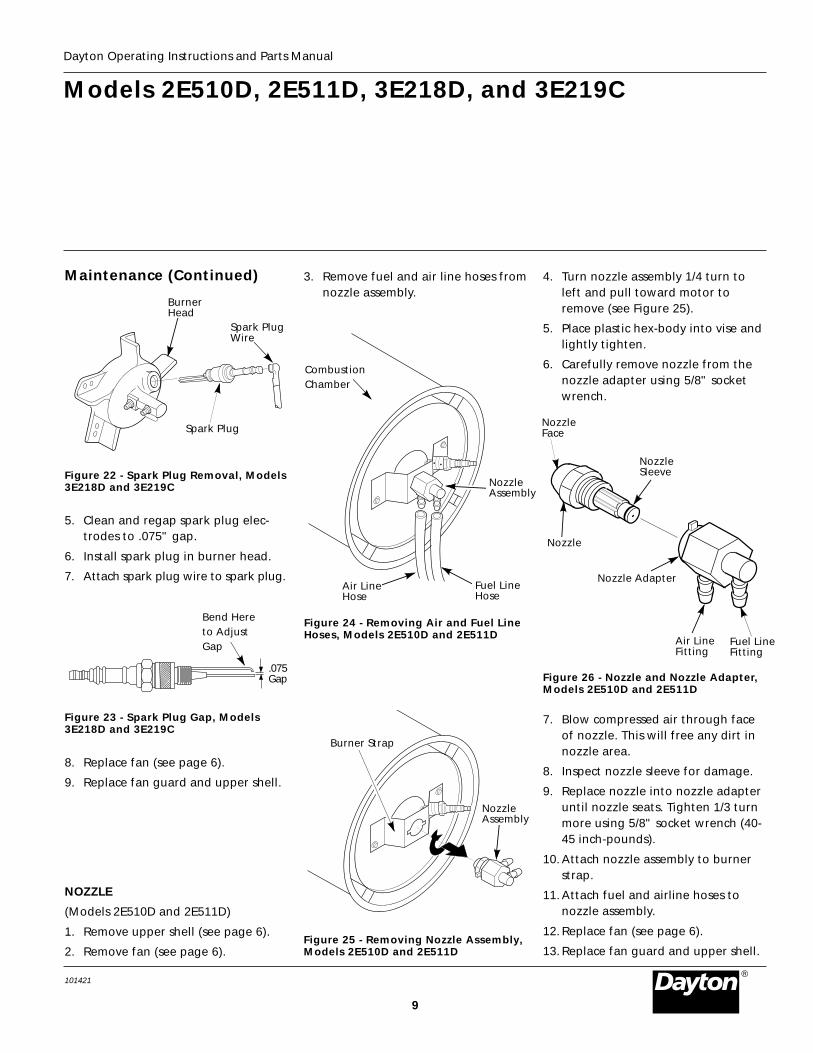
9
Models 2E510D, 2E511D, 3E218D, and 3E219C
Dayton Operating Instructions and Parts Manual
101421®
Spark PlugWire
Spark Plug
BurnerHead
Figure 22 - Spark Plug Removal, Models3E218D and 3E219C
Maintenance (Continued)
5. Clean and regap spark plug elec-trodes to .075" gap.
6. Install spark plug in burner head.
7. Attach spark plug wire to spark plug.
Bend Hereto AdjustGap
Figure 23 - Spark Plug Gap, Models3E218D and 3E219C
8. Replace fan (see page 6).
9. Replace fan guard and upper shell.
NOZZLE
(Models 2E510D and 2E511D)
1. Remove upper shell (see page 6).
2. Remove fan (see page 6).
3. Remove fuel and air line hoses fromnozzle assembly.
Figure 25 - Removing Nozzle Assembly,Models 2E510D and 2E511D
NozzleAssembly
Burner Strap
Figure 24 - Removing Air and Fuel LineHoses, Models 2E510D and 2E511D
Fuel LineHose
4. Turn nozzle assembly 1/4 turn toleft and pull toward motor toremove (see Figure 25).
5. Place plastic hex-body into vise andlightly tighten.
6. Carefully remove nozzle from thenozzle adapter using 5/8" socketwrench.
Air LineFitting
Fuel LineFitting
Nozzle
NozzleSleeve
NozzleFace
Figure 26 - Nozzle and Nozzle Adapter,Models 2E510D and 2E511D
7. Blow compressed air through faceof nozzle. This will free any dirt innozzle area.
8. Inspect nozzle sleeve for damage.
9. Replace nozzle into nozzle adapteruntil nozzle seats. Tighten 1/3 turnmore using 5/8" socket wrench (40-45 inch-pounds).
10. Attach nozzle assembly to burnerstrap.
11. Attach fuel and airline hoses tonozzle assembly.
12. Replace fan (see page 6).
13. Replace fan guard and upper shell.
CombustionChamber
NozzleAssembly
Air LineHose
Nozzle Adapter
.075Gap

Dayton Operating Instructions and Parts Manual
10
Dayton PortableOil-Fired Heaters
®
101421
Maintenance (Continued)
NOZZLE
(Models 3E218D and 3E219C)
1. Remove upper shell (see page 6).
2. Remove fan (see page 6).
3. Remove fuel and air line hosesfrom burner head.
4. Remove spark plug wire from sparkplug.
5. Remove spark plug from burnerhead using 13/16" open-endwrench.
6. Remove three screws using 5/16"nut-driver and remove burner headfrom combustion chamber.
BurnerHead
Air LineFitting
FuelLineFitting
Nozzle Sleeve
Nozzle
Nozzle Face
Figure 28 - Removing Nozzle, Models3E218D and 3E219C
10. Inspect nozzle sleeve for damage.
11. Replace nozzle into burner head andtighten firmly (80-110 inch-pounds).
12. Attach burner head to combustionchamber.
13. Install spark plug in burner head.
14. Attach spark plug wire to spark plug.
15. Attach fuel and airline hoses toburner head.
16. Replace fan (see page 6).
17. Replace fan guard and upper shell.
7. Place burner head into vise andlightly tighten.
8. Carefully remove nozzle fromburner head using 5/8" socketwrench (see Figure 28).
9. Blow compressed air through faceof nozzle. This will free any dirt innozzle area.
SparkPlugWire
00 BURNER HEAD DOM. PFA/P 021A
Burner Head
Spark Plug
Fuel LineHose
Air LineHose
Figure 27 - Removing Burner Head,Models 3E218D and 3E219C
Figure 30 - Rotor Location, Models3E218D and 3E219C
OR-Domestic PFA/P 059A
BladePump Plate
Air Intake FilterFilter End Cover
Insert
Rotor
Air Output Filter
OTOR-Domestic PFA/P 056B
Pump Plate
Blade
Air Intake Filter
Filter End Cover
Insert
Rotor
Air Output Filter
Figure 29 - Rotor Location, Models2E510D and 2E511D
Screw
CombustionChamber
PUMP ROTOR
(Procedure if rotor is binding)
1. Remove upper shell (see page 6).
2. Remove filter end cover screwsusing 5/16" nut-driver.
3. Remove filter end cover and airfilters.
4. Remove pump plate screws using5/16" nut-driver.
Fan Guard
Fan Guard
5. Remove pump plate.
6. Remove rotor, insert, and blades.
7. Check for debris in pump. If debris isfound, blow out with compressed air.
8. Install insert and rotor.
9. Check gap on rotor. Adjust to .003"/.004" if needed (see Figure 31,page 11).

11
Models 2E510D, 2E511D, 3E218D, and 3E219C
Dayton Operating Instructions and Parts Manual
101421®
NOTE: If rotor is still binding, proceedas follows.
13. Perform steps 1 through 6 (seepage 10).
14. Place fine grade sandpaper (600grit) on flat surface. Sand rotorlightly in “figure 8” motion fourtimes (see Figure 32).
15. Reinstall insert and rotor.
16. Perform steps 10 through 12 above.
Maintenance (Continued)
.003"/.004"Gap Measuredwith FeelerGauge
Gap AdjustingScrew
Blade
Gap AdjustingScrew
Rotor
Figure 31 - Gap Adjusting ScrewLocations
NOTE: Rotate rotor one full turn toinsure the gap is .003"/.004" attightest position. Adjust if needed.
10. Install blades, pump plate, airfilters, and filter end cover.
11. Replace fan guard and upper shell.
12. Adjust pump pressure (see page 7).
Sandpaper
Figure 32 - Sanding Rotor
Never service heater while it is plugged in, operating, or hot. Severe burns and electrical shock can occur.
Preventative Maintenance Schedule
Fuel tank Flush every 150-200 hours of operation or as needed. See Storing, Transporting, or Shipping,above.
Air output and Replace every 500 hours of operation or once a year. See Air Output, Air Intake, and Lintlint filters Filters, page 7.
Air intake filter Wash and dry with soap and water every 500 hours of See Air Output, Air Intake, and Lintoperation or as needed. Filters, page 7.
Fuel filter Clean twice a heating season or as needed. See Fuel Filter, page 7.Spark plug Clean and regap every 600 hours operation or replace as needed. See Spark Plug, page 8.Fan blades Clean every season or as needed. See Fan, page 6.Motor Not required/permanently lubricated.
How Often How ToItem
1. Drain fuel tank.NOTE: Some models have drain plug onunderside of fuel tank. If so, remove drainplug to drain all fuel. If heater does nothave drain plug, drain fuel through fuelcap opening. Be sure all fuel is removed.2. Replace drain plug if provided.3. If any debris is noted in old fuel, add
1 or 2 quarts of clean kerosene totank, stir, and drain again. This willprevent excess debris from cloggingfilters during future use.
4. Replace fuel cap or drain plug. Prop-erly dispose of old and dirty fuel.Check with local automotive servicestations that recycle oil.
5. If storing, store heater in dry place.Make sure storage place is free of dustand corrosive fumes.
IMPORTANT: Do not store kerosene oversummer months for use during next heat-ing season. Using old fuel could damageheater.
Storing Transporting, orShipping
NOTE: If shipping, transport companiesrequire fuel tanks to be empty.

Dayton Operating Instructions and Parts Manual
12
Dayton PortableOil-Fired Heaters
®
101421
For Replacement Parts, call 1-800-323-0620Please provide following information:-Model number-Serial number (if any)-Part descriptions and number as shown in parts list
Address parts correspondence to:Grainger Parts OperationsP.O. Box 30741657 Shermer RoadNorthbrook, IL 60065-3074
Figure 33 - Motor and Pump Assembly forModels 2E510D and 2E511D
2E510D, 2E511D, 3E218D, and 3E219C
Figure 34 - Burner Head Assembly forModels 3E218D and 3E219C
Figure 35 - Motor and Pump Assembly forModels 3E218D and 3E219C
1
2
3 4 5
6
8
7
9
13
1011
15
14
1817
16
141516
13
69 8
1110
17
12
7
25
4
213
12
1
3
24 5
7
6

13
Models 2E510D, 2E511D, 3E218D, and 3E219C
Dayton Operating Instructions and Parts Manual
101421®
Replacement Parts ListModels 2E510D, 2E511D, 3E218D and 3E219C Portable Oil-Fired Heaters
2E510D, 2E511D, 3E218D, and 3E219C
Ref. Part 2E510D 2E511DNo. Description Number Qty. Qty.Ref. Part 2E510D 2E511DNo. Description Number Qty. Qty.
Ref. Part 2E510D 2E511DNo. Description Number Qty. Qty.
11 Pressure Relief Spring M10993-1 1 1
12 Plug M22997 1 1
13 1/4" Diameter Steel Ball M8940 1 1
14 Output Filter M29612-01 1 1
15 #10-32x1" Screw *M12461-31 6 6
16 90° Elbow M50016 1 1
17 Blade M8643 4 —
Blade M8643-2 — 4
18 #10-32x1/4" Screw *FHPF3-5C 2 —
#10-32 x 5/8" Screw *FHPF3-6C — 2
1 Motor 102001-01 1 1
2 Pump Body 079975-02 1 —
Pump Body 079975-03 — 1
3 Insert M22009 1 1
4 Rotor M22456-1 1 —
Rotor M22456-2 — 1
5 End Pump Cover M29608 1 1
6 Lint Filter M29632 1 1
7 Intake Filter M29633 1 1
8 End Cover M29609 1 1
9 #10-32x1" Screw *M12461-31 3 3
10 Adjusting Screw M27694 1 1
(*) Standard hardware item, available locally.
Motor and Pump Assembly for Models 2E510D and 2E511D - Figure 33
Ref. Part 2E510D 2E511DNo. Description Number Qty. Qty.
Ref. Part 3E218D 3E219CNo. Description Number Qty. Qty.
Ref. Part 3E218D 3E219CNo. Description Number Qty. Qty.
1 End Filter Cover M16545 1 1
2 #10-32x1" Screw *M12461-31 10 10
3 Intake Filter M12179 1 1
4 Output Filter M12244-1 1 1
5 Lint Filter M11637 1 1
6 End Pump Cover M50545 1 1
7 Blade M8643 4 4
8 Rotor Pump M22456-1 1 1
9 Rotor Insert M22009 1 1
10 Pump Body 079975-02 1 1
11 #10-32x1/4" Screw *FHPF3-5C 2 2
12 Barb Fitting M50820-02 1 1
13 Plug M22997 1 1
14 Adjusting Screw M27694 1 1
15 Relief Spring M10993-1 1 1
16 1/4" Diameter Ball M8940 1 1
17 Motor 097300-02 1 1
(*) Standard hardware item, available locally.
Motor and Pump Assembly for Models 3E218D and 3E219C - Figure 35
1 Nozzle HA3009 1 —
Nozzle HA3011 — 1
2 Nozzle Washer M10659-1 2 2
3 Nozzle Spring M10809-1 1 1
Ref. Part 2E510D 2E511DNo. Description Number Qty. Qty.
Ref. Part 3E218D 3E219CNo. Description Number Qty. Qty.
Ref. Part 3E218D 3E219CNo. Description Number Qty. Qty.
4 Nozzle Sleeve M8882 1 1
5 Burner Head Body M50924-03 1 1
6 Barb Fitting M50820-02 2 1
7 Spark Plug HA3012 1 1
Burner Head Assembly for Models 3E218D and 3E219C - Figure 34

Dayton Operating Instructions and Parts Manual
14
Dayton PortableOil-Fired Heaters
®
101421
Please provide following information:-Model number-Serial number (if any)-Part descriptions and number as shown in parts list
Address parts correspondence to:Grainger Parts OperationsP.O. Box 30741657 Shermer RoadNorthbrook, IL 60065-3074
2E510D and 2E511D
Figure 36 - Replacement Parts Illustration for Models 2E510D and 2E511D
34
1
2
3
4
5
67
8
9
10
11
12
13
14
15
16
9-19-2
9-39-4
9-5
17
18
19
20
21
22
23
24
25 26
27
30
31
32
3336
37
38
39
28
29
35
40
41
For Replacement Parts, call 1-800-323-0620

15
Models 2E510D, 2E511D, 3E218D, and 3E219C
Dayton Operating Instructions and Parts Manual
101421®
2E510D and 2E511D
(*) Standard hardware item, available locally.
(∆) Not shown.
(†) Not available as an assembly, see pages 14 and 15.
Replacement Parts ListModels 2E510D and 2E511D Portable Oil-Fired Heaters
1 Handle M51104-01 1 1
2 Upper Shell 098511-34 1 1
3 #10-16x3/4" Screw *M11084-29 2 2
4 #10-16x1/2" Screw *100647-01 6 6
5 Combustion Chamber 099961-01 1 —
Combustion Chamber 098512-32 — 1
6 #6-32x3/8" Screw *M10908-2 2 2
7 Photocell Bracket M16660 1 1
8 Photocell Assembly HA3019 1 1
9 Burner Assembly † 1 1
9-1 Nozzle HA3006 1 —
Nozzle 100735-17 — 1
9-2 Spark Plug HA3013 1 1
9-3 Nozzle Adapter 079980-01 1 1
9-4 Bracket 097124-01 1 1
9-5 14mm Nut M29824 1 1
10 #10-16x3/8" Screw *M11084-26 2 2
11 Fan M30884 1 1
12 Motor Package Assembly † 1 1
13 Fan Guard M51105-01 1 1
14 Power Cord 098219-18 1 1
15 Strain Relief Bushing M11143-1 1 1
16 Hex Lock Nut NTC-4C 2 2
17 #10-16x3/8" Screw *M11084-26 2 2
18 Rubber Bumper M50631 2 2
19 Side Cover M50899-03AA 1 1
20 Motor Bracket 098138-01 1 1
21 Bushing M30865-02 2 2
22 Clip Nut M11271-8 6 6
23 Bushing (wires) M50104-02 1 1
24 #10-16x3/8" Screw *M11084-26 6 6
25 #8-18x1/2" Screw *M15823-39 1 1
26 Lower Shell 098511-14 1 1
27 Rubber Airline M29652-04 1 1
28 Ignitor 098557-06 1 1
29 #10-16x3/4" Screw *M11084-29 2 2
30 Fuel Line M29652-05 1 1
31 Fuel Filter Assembly M50876-04 1 —
Fuel Filter Assembly M50876-05 — 1
32 Rubber Bushing M10990-3 1 1
33 Wire Assembly (red, 8 1/2") M16841-57 1 1
34 Terminal Board 099125-02 1 1
35 Rivet 099157-01 1 1
36 Flame-out Control HA3003 1 1
37 Fuel Cap (Includes Gasket) 097702-01 1 1
38 Fuel Tank 098513-23 1 —
Fuel Tank 098513-24 — 1
39 Heat Shield M51108-01 1 1
40 3/8-27 Hex Nut *099177-01 1 1
41 Wire Assembly
(green/yellow, 15 7/8") M9900-192 1 1
∆ General Information Decal 101685-01 1 —
∆ General Information Decal 101685-02 — 1
∆ Thermostat Control (opt.) 2E535 1 1
∆ Thermostat Control (opt.) 2E817 1 1
Ref. Part 2E510D 2E511DNo. Description Number Qty. Qty.
Ref. Part 2E510D 2E511DNo. Description Number Qty. Qty.

Dayton Operating Instructions and Parts Manual
16
Dayton PortableOil-Fired Heaters
®
101421
For Replacement Parts, call 1-800-323-0620Please provide following information:-Model number-Serial number (if any)-Part descriptions and number as shown in parts list
Address parts correspondence to:Grainger Parts OperationsP.O. Box 30741657 Shermer RoadNorthbrook, IL 60065-3074
3E218D
Figure 37 - Replacement Parts Illustration for Model 3E218D
12
3
4
5
6
7
823
19
9
10
11
12
1525
2627
24
28
44
20
22
21
30
31
3334
35
36
14
13
40
39
17
18
32
37
38
16
26
43
41
42

17
Models 2E510D, 2E511D, 3E218D, and 3E219C
Dayton Operating Instructions and Parts Manual
101421®
3E218D
Replacement Parts ListModel 3E218D Portable Oil-Fired Heater
(*) Standard hardware item, available locally.
(∆) Not shown.
(†) Not available as an assembly, see pages 14 and 15.
Ref. Part 2E510D 2E511DNo. Description Number Qty. Qty.
Ref. Part 3E218DNo. Description Number Qty.
25 Bushing M50104-03 2
26 Bushing M50104-01 2
27 #10-16x1/2" Screw *M11084-27 6
28 Clip Nut M11271-8 8
29 #8-18x1/2" Screw *M15823-39 1
30 Fuel Tank 098513-21 1
31 Fuel Cap (Includes Gasket) 097702-01 1
32 Flame-out Control HA3003 1
33 Strain Relief Bushing M11143-1 1
34 Power Cord 098219-19 1
35 Side Cover M51077-01AA 1
36 #10-16x1/2" Screw *M11084-27 4
37 Terminal Board 099125-03 1
38 Rivet 099157-01 1
39 Wire Assembly (red, 16") 079010-20 1
40 Wire Assembly (red, 8 1/2") M16841-57 1
41 3/8-27 Hex Nut *099177-01 1
42 Button Plug 099213-01 1
43 Drain Plug (Includes O-ring) M27417 1
44 Wire Assembly M9900-192 1
∆ Thermostat Control (opt.) 2E535 1
∆ Thermostat Control (opt.) 2E817 1
∆ General Information Decal 101685-03 1
Ref. Part 3E218DNo. Description Number Qty.
1 Upper Shell 098511-164 1
2 #10-16x1/2" Screw *100647-01 8
3 Combustion Chamber 098512-31 1
4 Photocell Bracket M16660 1
5 #6-32x3/8" Screw *M10908-2 2
6 Photocell Assembly HA3019 1
7 Burner Assembly †
8 #10-16x1/2" Screw *M11084-27 3
9 Fan 097293-01 1
10 Motor and Pump Assembly † 1
11 Rubber Bumper M50631 2
12 Motor Mounting Bracket 098138-02 1
13 Solid State Relay 097061-01 1
14 #8-18x1/2" Screw *M15823-39 2
15 Hex Lock Nut NTC-4C 2
16 Fan Guard M51114-01 1
17 Ignitor 102482-01 1
18 #10-16x3/4" Screw *M11084-29 2
19 Fuel Line M51345-01 1
20 Fuel Filter M51150-01 1
21 Fuel Line Tube M51151-01 1
22 Rubber Bushing M10990-3 1
23 Airline M50814-03 1
24 Lower Shell 098511-163 1

Dayton Operating Instructions and Parts Manual
18
Dayton PortableOil-Fired Heaters
®
101421
For Replacement Parts, call 1-800-323-0620Please provide following information:-Model number-Serial number (if any)-Part descriptions and number as shown in parts list
Address parts correspondence to:Grainger Parts OperationsP.O. Box 30741657 Shermer RoadNorthbrook, IL 60065-3074
3E219C
Figure 38 - Replacement Parts Illustrationfor Model 3E219C
30
31
4032
12
3
4
5
6
7
823
19
9
10
11
12
1525
2627
24
28
29
20
22
21
3334
35
36
14
13
39
17
18
37
38
16
26
41
23
44
43
42
27
45

19
Models 2E510D, 2E511D, 3E218D, and 3E219C
Dayton Operating Instructions and Parts Manual
101421®
3E219C
Replacement Parts ListModel 3E219C Portable Oil-Fired Heater
Ref. Part 3E219CNo. Description Number Qty.
Ref. Part 3E219CNo. Description Number Qty.
1 Upper Shell 098511-164 1
2 #10-16x1/2" Screw *100647-01 8
3 Combustion Chamber 098512-28 1
4 Photocell Bracket 099229-01 1
5 #6-32x3/8" Screw *M10908-2 2
6 Photocell Assembly HA3019 1
7 Burner Assembly † 1
8 #10-16x1/2" Screw *M11084-27 3
9 Fan 097293-01 1
10 Motor and Pump Assembly † 1
11 Rubber Bumper M50631 2
12 Motor Mounting Bracket 098138-02 1
13 Solid State Relay 097061-01 1
14 #8-18x1/2" Screw *M15823-39 2
15 Hex Lock Nut, 1/4-20 NTC-4C 2
16 Fan Guard M51114-01 1
17 Ignitor 102482-01 1
18 #10-16x3/4" Screw *M11084-29 2
19 Fuel Line M51345-02 1
20 Fuel Filter M51150-01 1
21 Fuel Line Tube M51151-02 1
22 Rubber Bushing M10990-3 1
23 Airline M50814-03 1
24 Lower Shell 098511-163 1
25 Bushing M50104-03 2
26 Bushing M50104-01 2
27 #10-16x1/2" Screw *M11084-27 8
28 Clip Nut M11271-8 8
29 #8-18x1/2" Screw *M15823-39 1
30 Fuel Tank 098513-55 1
31 Fuel Cap (Includes Gasket) 097702-01 1
32 Flame-out Control HA3003 1
33 Strain Relief Bushing M11143-1 1
34 Power Cord 098219-19 1
35 Side Cover M51077-01AA 1
36 #10-16x1/2" Screw *M11084-27 4
37 Terminal Board 099125-03 1
38 Rivet 099157-01 1
39 Wire Assembly (red, 18") 079010-20 1
40 Wire Assembly (red, 8 1/2") M16841-57 1
41 Drain Plug (includes O-ring) M27417 1
42 #10-16x3/8" Screw *099230-01 2
43 3/8-27 Hex Nut *099177-01 1
44 Button Plug 099213-01 1
45 Wire Assembly M9900-192 1
∆ Thermostat Control (opt.) 2E535 1
∆ Thermostat Control (opt.) 2E817 1
∆ General Information Decal 101685-04 1
(*) Standard hardware item, available locally.
(∆) Not shown.
(†) Not available as an assembly, see pages 14 and 15.

Dayton Operating Instructions and Parts Manual
20
Dayton PortableOil-Fired Heaters
®
101421
Replacement Parts List for Handle and Wheel Group Models 3E218D and 3E219C
Figure 39 - Handle and Wheel Assembly
3
4
58
76
21Ref. Part NumberNo. Description 3E218D 3E519C Qty.
1 Front Handle HA2203 HA2204 1
2 Rear Handle HA2203 HA2204 1
3 Oval Head Screw,#10 - 24 x 1 3/4" M12345-33 M12345-33 8
4 Wheel Support Frame M12342-3 M12831-3 1
5 Torque LockHex Nut, 10-24 NTC-3C NTC-3C 8
6 Axle M51015-01 M16801-2 1
7 Wheel 097896-01 097896-01 2
8 Cap Nut M28526 M28526 2
Flame-out Control * HA3003 HA3003 HA3003 HA3003
Spark Plug * HA3013 HA3013 HA3012 HA3012
Filter Kit * HA3014 HA3014 HA3017 HA3018
Nozzle Kit HA3006 100735-17 HA3009 HA3011
Rotor/Air Pump Kit * HA3004 HA3005 HA3004 HA3004
Handle — — HA2203 HA2204
Photocell * HA3019 HA3019 HA3019 HA3019
Pump Adjustment HA3020 HA3020 HA3020 HA3020
Tune Up Kit 5E196 5E196 5E198 5E197
(*) Included in Tune Up Kit
Part Numbers for Models2E510D 2E511D 3E218D 3E219C
Maintenance Kits
Air Gauge Kit HA1180 HA1180 HA1180 HA1180
Standard Wheels and Handle Kit HA1206 HA1206 —— ——
Heavy Duty Wheels and Handle Kit HA1202 HA1202 —— ——
Interchangable Thermostat 2E535 or 2E817 for All Models (2E535 is Hydraulic, 2E537 is Bi-Metal)
2E510D 2E511D 3E218D 3E219C
Accessories

21
Models 2E510D, 2E511D, 3E218D, and 3E219C
Dayton Operating Instructions and Parts Manual
101421®
Wiring Diagrams
Figure 41 - Wiring Diagram for Models 3E218D and 3E219C
White
Black
Blue
Green
Power Plug120V/60Hz
Photocell
Spark PlugIgnitorFlame-
OutControl
B
ResetButton
RRed
Blue
White
White
White
White
Red
Red
GreenTerminal
BoardMotor
Figure 40 - Wiring Diagram for Models 2E510D and 2E511D
White
Black
Blue
Green
Power Plug120V/60Hz
Photocell
Spark PlugIgnitorFlame-
OutControl
B
ResetButton
RRed
MotorBlue
White
White
White
White
Red
Red
GreenTerminal
Board
RedRelayBlack

Dayton Operating Instructions and Parts Manual
22
Dayton PortableOil-Fired Heaters
®
101421
Troubleshooting Chart
Possible Cause(s) Corrective Action
Never service heater while it is plugged in, operating, or hot.Severe burns and electrical shock can occur.
Heater ignites, but flame-out controlshuts off heater after a short period oftime
1. See Pump Pressure Adjustment, page 7
2. See Air Output, Air Intake and LintFilters, page 7
3. See Fuel Filter, page 7
4. See Nozzle, page 9
5. Clean photocell lens
6. Replace flame-out control
1. Wrong pump pressure
2. Dirty air output, air intake and lint filters
3. Dirty fuel filter
4. Dirt in nozzle
5. Dirty photocell lens
6. Bad flame-out control
Symptom
Heater will not ignite, but motor runsfor a short period of time
1. Wrong pump pressure
2. Carbon deposits on spark plug and/or improper gap
3. Dirty fuel filter
4. Dirt in nozzle
5. Water in fuel tank
6. Electronic ignitor notgrounded
7. Bad electronic ignitor
1. See Pump Pressure Adjustment, page 7
2. See Spark Plug, page 8
3. See Fuel Filter, page 7
4. See Nozzle, page 9
5. Drain and flush fuel tank with cleankerosene. See Storing, Transporting,or Shipping, page 11
6. Make sure electronic ignitor mount-ing is tight
7. Replace electronic ignitor
High Voltage!
Motor does not start when heater isplugged in, fan rotates slowly or doesnot turn
1. Flame-out control not reset
2. Solid state relay notallowed to reset
3. Binding pump rotor
1. Press flame-out control reset button
2. Wait two minutes before trying torestart heater
3. If fan is hard to turn, see PumpRotor, page 10

23
Models 2E510D, 2E511D, 3E218D, and 3E219C
Dayton Operating Instructions and Parts Manual
101421®
____________________________________________________________________________________________________________________
____________________________________________________________________________________________________________________
____________________________________________________________________________________________________________________
____________________________________________________________________________________________________________________
____________________________________________________________________________________________________________________
____________________________________________________________________________________________________________________
____________________________________________________________________________________________________________________
____________________________________________________________________________________________________________________
____________________________________________________________________________________________________________________
____________________________________________________________________________________________________________________
____________________________________________________________________________________________________________________
____________________________________________________________________________________________________________________
____________________________________________________________________________________________________________________
____________________________________________________________________________________________________________________
____________________________________________________________________________________________________________________
____________________________________________________________________________________________________________________
____________________________________________________________________________________________________________________
____________________________________________________________________________________________________________________
____________________________________________________________________________________________________________________
____________________________________________________________________________________________________________________
____________________________________________________________________________________________________________________
____________________________________________________________________________________________________________________
____________________________________________________________________________________________________________________
____________________________________________________________________________________________________________________
____________________________________________________________________________________________________________________
____________________________________________________________________________________________________________________
____________________________________________________________________________________________________________________
____________________________________________________________________________________________________________________
____________________________________________________________________________________________________________________
Notes

Dayton Operating Instructions and Parts Manual 2E510D, 2E511D, 3E218D, and 3E219C
Manufactured for Dayton Electric Mfg. Co.Niles, Illinois 60714
101421-01Rev. C03/98
Version B - For Reduction G016.J
®
Dayton PortableOil-Fired Heaters
LIMITED WARRANTY
Dayton One-Year Limited Warranty. Portable Oil-Fired heaters, Models 2E510D, 2E511D, 3E218D and 3E219C, are warranted by DaytonElectric Mfg. Co. (Dayton) to the original user against defects in workmanship or materials under normal use for one year after date of purchase.Any part which is determined to be defective in material or workmanship and returned to an authorized service location, as Dayton designates,shipping costs prepaid, will be, as the exclusive remedy, repaired or replaced at Dayton’s option. For limited warranty claim procedures, seePROMPT DISPOSITION below. This limited warranty gives purchasers specific legal rights which vary from state to state.
Limitation of Liability. To the extent allowable under applicable law, Dayton’s liability for consequential and incidental damages is expresslydisclaimed. Dayton’s liability in all events is limited to, and shall not exceed, the purchase price paid.
Warranty Disclaimer. Dayton has made a diligent effort to illustrate and describe the products in this literature accurately; however, suchillustrations and descriptions are for the sole purpose of identification, and do not express or imply a warranty that the products aremerchantable, or fit for a particular purpose, or that the products will necessarily conform to the illustrations or descriptions.
Except as provided below, no warranty or affirmation of fact, expressed or implied, other than as stated in “LIMITED WARRANTY” above ismade or authorized by Dayton.
Product Suitability. Many states and localities have codes and regulations governing sales, construction, installation, and/or use of productsfor certain purposes, which may vary from those in neighboring areas. While Dayton attempts to assure that its products comply with suchcodes, it cannot guarantee compliance, and cannot be responsible for how the product is installed or used. Before purchase and use of aproduct, please review the product application, and national and local codes and regulations, and be sure that the product, installation, anduse will comply with them.
Certain aspects of disclaimers are not applicable to consumer products; e.g., (a) some states do not allow the exclusion or limitation of incidentalor consequential damages, so the above limitation or exclusion may not apply to you; (b) also, some states do not allow limitations on howlong an implied warranty lasts, consequently the above limitation may not apply to you; and (c) by law, during the period of this limitedwarranty, any implied warranties of merchantability or fitness for a particular purpose applicable to consumer products purchased byconsumers, may not be excluded or otherwise disclaimed.
Prompt Disposition. Dayton will make a good faith effort for prompt correction or other adjustment with respect to any product which provesto be defective within limited warranty. For any product believed to be defective within limited warranty, first write or call dealer from whomproduct was purchased. Dealer will give additional directions. If unable to resolve satisfactorily, write to Dayton at address below, giving dealer’sname, address, date and number of dealer’s invoice, and describing the nature of the defect. Title and risk of loss pass to buyer on deliveryto common carrier. If product was damaged in transit to you, file claim with carrier.
Manufactured for Dayton Electric Mfg. Co., 5959 W. Howard St., Niles, Illinois 60714 U.S.A.
101421 01
NOT A UPC