Proper Orthogonal Decomposition of Flexible Clap and Fling ... · The majority of the...
18
American Institute of Aeronautics and Astronautics 1 Proper Orthogonal Decomposition of Flexible Clap and Fling Motions via High-Speed Deformation Measurements Bret Stanford 1 , Danny Lacore 2 U.S. Air Force Research Laboratory, Wright-Patterson AFB, OH, 45433 Roberto Albertani 3 University of Florida Research and Engineering Education Facility, Shalimar, FL, 32579 and Gregory Parker 4 , Robert Walker 5 , David Curtis 6 U.S. Air Force Research Laboratory, Wright-Patterson AFB, OH, 45433 Many complex unsteady mechanisms are thought to facilitate the high efficiency and agility commonly observed in small biological flyers. One of these, the flexible clap and fling maneuver, has not been extensively studied; an experimental characterization is the focus of this work. The clap-fling mechanism is approximated with a single flexible membrane flapping wing, replacing the symmetry plane between two wings with a splitter plate simulating the pair wing. This produces a complex vibro-impact aeroelastic problem, the deformation resulting from which is measured with a high-speed visual image correlation system. A low-dimensional representation of the ensuing large data set is obtained with proper orthogonal decomposition. The POD modes, and the relative importance of each, can help elucidate crucial mechanisms and relationships within the flapping system, and are computed for various membrane wing structures and flapping frequencies, with or without the presence of the splitter plate. I. Introduction HE aerospace engineering community is increasingly interested in the flight mechanics and dynamics of small flapping air vehicles in the low Reynolds number regime (Figure 1), as well as natural flyers. The study of flying creatures can offer a significant source of bio-inspiration in several aeronautical disciplines, including highly unsteady fluid dynamics, fluid-structure interactions and dynamically adaptive structures. This work is concerned with the structural dynamics of a biologically-inspired flapping wing equipped with a pliant membrane. A detailed knowledge of the complex physics that enable the lift and thrust generation of flexible flapping wings, including the complex fluid-structure interactions, can assist in future design efforts for micro and nano air vehicles. Unfortunately, the salient features and relationships are not always easily understood when dealing with large quantities of unsteady aeroelastic data. Towards this end, proper orthogonal decomposition (POD) is used to extract fundamental aspects and mechanisms of the flapping wing physics. Many unsteady mechanisms are thought to contribute to the spectacular agility commonly seen in biological flyers; of particular interest for this work is the clap-fling mechanism. This is a well-known flapping flight mechanism, and is well-explained from a fluid dynamic aspect. For flexible wings, the term “clap and peel” is used in the literature, reflecting the deformation of two flexible trailing edges as they are peeled apart for the unsteady vortex generation. The mechanism is a wing interference phenomenon with beneficial force-production effects, 1 National Research Council Postdoctoral Researcher: [email protected]. 2 Second Lieutenant, U.S. Air Force: [email protected]. 3 Research Assistant Professor: [email protected]. 4 Research Aerospace Engineer: [email protected]. 5 Captain, U.S. Air Force: [email protected]. 6 Captain, U.S. Air Force: [email protected]. T 48th AIAA Aerospace Sciences Meeting Including the New Horizons Forum and Aerospace Exposition 4 - 7 January 2010, Orlando, Florida AIAA 2010-1026 This material is declared a work of the U.S. Government and is not subject to copyright protection in the United States.
Transcript of Proper Orthogonal Decomposition of Flexible Clap and Fling ... · The majority of the...

American Institute of Aeronautics and Astronautics
1
Proper Orthogonal Decomposition of Flexible Clap and Fling Motions via High-Speed Deformation Measurements
Bret Stanford1, Danny Lacore2
U.S. Air Force Research Laboratory, Wright-Patterson AFB, OH, 45433
Roberto Albertani3
University of Florida Research and Engineering Education Facility, Shalimar, FL, 32579
and
Gregory Parker4, Robert Walker5, David Curtis6
U.S. Air Force Research Laboratory, Wright-Patterson AFB, OH, 45433
Many complex unsteady mechanisms are thought to facilitate the high efficiency and agility commonly observed in small biological flyers. One of these, the flexible clap and fling maneuver, has not been extensively studied; an experimental characterization is the focus of this work. The clap-fling mechanism is approximated with a single flexible membrane flapping wing, replacing the symmetry plane between two wings with a splitter plate simulating the pair wing. This produces a complex vibro-impact aeroelastic problem, the deformation resulting from which is measured with a high-speed visual image correlation system. A low-dimensional representation of the ensuing large data set is obtained with proper orthogonal decomposition. The POD modes, and the relative importance of each, can help elucidate crucial mechanisms and relationships within the flapping system, and are computed for various membrane wing structures and flapping frequencies, with or without the presence of the splitter plate.
I. Introduction HE aerospace engineering community is increasingly interested in the flight mechanics and dynamics of small flapping air vehicles in the low Reynolds number regime (Figure 1), as well as natural flyers. The study of
flying creatures can offer a significant source of bio-inspiration in several aeronautical disciplines, including highly unsteady fluid dynamics, fluid-structure interactions and dynamically adaptive structures. This work is concerned with the structural dynamics of a biologically-inspired flapping wing equipped with a pliant membrane. A detailed knowledge of the complex physics that enable the lift and thrust generation of flexible flapping wings, including the complex fluid-structure interactions, can assist in future design efforts for micro and nano air vehicles. Unfortunately, the salient features and relationships are not always easily understood when dealing with large quantities of unsteady aeroelastic data. Towards this end, proper orthogonal decomposition (POD) is used to extract fundamental aspects and mechanisms of the flapping wing physics.
Many unsteady mechanisms are thought to contribute to the spectacular agility commonly seen in biological flyers; of particular interest for this work is the clap-fling mechanism. This is a well-known flapping flight mechanism, and is well-explained from a fluid dynamic aspect. For flexible wings, the term “clap and peel” is used in the literature, reflecting the deformation of two flexible trailing edges as they are peeled apart for the unsteady vortex generation. The mechanism is a wing interference phenomenon with beneficial force-production effects,
1 National Research Council Postdoctoral Researcher: [email protected]. 2 Second Lieutenant, U.S. Air Force: [email protected]. 3 Research Assistant Professor: [email protected]. 4 Research Aerospace Engineer: [email protected]. 5 Captain, U.S. Air Force: [email protected]. 6 Captain, U.S. Air Force: [email protected].
T
48th AIAA Aerospace Sciences Meeting Including the New Horizons Forum and Aerospace Exposition4 - 7 January 2010, Orlando, Florida
AIAA 2010-1026
This material is declared a work of the U.S. Government and is not subject to copyright protection in the United States.

American Institute of Aeronautics and Astronautics
2
wherein two wing surfaces press together and are then pulled apart during the upper part of the flapping stroke, originally described by Weis-Fogh [1] for the small wasp Encarsia and by Lighthill [2]. As the fling motion begins, the interference starts the generation of a circulation around each wing, which is independent of quasi-steady considerations and creates circulatory lift even at very low Reynolds numbers [1]. The kinematics of the clap-fling mechanism is also described by Ellington [3]. The time that the wings remain clapped in small insects is generally not significant with respect to the entire stroke cycle, but, as noted by Ennos [4], unsteady mechanisms may be necessary to explain the high lift produced by flapping wings with a rapid built up of circulations without translation of the wing-body system. The author invokes the clap-fling mechanism to explain how the circulation generated per unit length of the wing may exceed the value that would be created by steady translation. At low Reynolds numbers this circulation may become attached to the wing.
Figure 1. A 20 cm wingspan ornithopter with a flexible-wing during testing in the University of Florida REEF small wind tunnel.
Sane [5] introduced the view of the clap-fling mechanism as two separate aerodynamic phases through observations of the Encarsia formosa. During the wing clap the proximity of the wings annul the opposite circulations, attenuating of the trailing edge vorticity shed by each wing during the following stroke, effectively reducing the onset of the Wagner effect. Additionally, a beneficial jet of fluid is expelled from the clapping wings to provide further thrust. During the subsequent fling phase, a low-pressure region is generated between the two wings creating a rush of air, and providing an initial impetus for the onset of the attached vorticity around the two wings that will translate away from each other with bound circulation of opposite signs. The author observes that clap-fling is mainly utilized by small insects, and is unlikely to provide a general explanation for the high-lift coefficients of biological flyers. The phenomenon was noted by Cooter and Baker [6] for the hindwings of Locusta migratoria in climbing flight, in various Lepidoptera including the Large Cabbage White butterfly Pieris brassicae [3], [6], and is illustrated in high-speed images obtained by Albertani et al. [7] during experimental studies on the free flight of a Owl butterfly (Caligo tucer, Figure 2) and a Monarch butterfly (Donaus plexippus, Figure 3). In many cases the butterflies were observed using the clap-fling mechanism at the beginning of the flight when still perched on a still object, when the highest acceleration is needed for a steep climb.
Figure 2. Caligo tucer (Owl butterfly) wing motion during take-off: wings close together (left), clap (center),
followed by the onset of a near-fling starting at the leading edge of the forewings (right).

American Institute of Aeronautics and Astronautics
3
Figure 3. Donaus plexippus (Monarch butterfly) wing motion during take-off: wings close together (left), followed by a partial-clap of the hindwings (center), and fling (right).
Kawachi et al. [8] demonstrate a direct link between the acceleration observed during a butterfly’s take-off flight and the pressure drag generated by the wings in the “near-fling” motion. The authors also noted that the high-steep angle and sudden take-off is augmented using the wings interference effect during the first half of the downstroke. The enhanced lift coefficient of a damselfly Calopteryx splendens with respect to a dragonfly Sympetrum sanguineum was evaluated by Wakeling and Ellington [9] and attributed to the clap-fling action in the damselfly at the dorsal end of its stroke, the only kinematic difference in the wings of the two insects. Furthermore the clap-fling mechanism observed in the Calopteryx splendens is thought to reduce the aerodynamic power (again compared to the dragonfly) required for flight at the same velocity and same thrust, thus providing a more efficient means of flapping flight. This is a noteworthy ramification for the future design of artificial flappers, where the on-board energy budget is expected to be very limited.
This present work is focused on the elastic deformation aspects of the clap-fling mechanism, as observed by numerous researchers. The mechanism may also be involved in the wings muscles’ power output and the overall elastic energy exchange in the thorax-wing system. Wakeling and Ellington [9] observed that damselfly flights typically involve partial flings in which the wings do not stop at the supination, providing the insect the ability to recapture this elastic energy. The relevance of the elastic fluid-structure interactions involved in the clap-fling mechanism was originally noted by Ellington [10], who proposed that the relatively long clapped time for the wasp Encarsia may be connected with the elastic energy storage necessary for the high mechanical energy needed for the subsequent “fling” motion. The elastic deformation of the wing was observed during the stroke cycle by Wootton et al. [11] using sequences from a high-speed film of a desert locust Schistocera gregaria during tethered flight in a low-speed wind tunnel. At the beginning of the downstroke the hind wings peel apart, generating extra lift and developing a cambered section. The phenomenon resembling a clap-fling motion was described originally by Ellington [3], [12] as a near-clap and partial-peel for obtaining extra lift. The peeling effect, usually referred to as radial flexion, is accomplished by flexion of the vannus along lines parallel to the radiating veins.
The majority of the aforementioned research pertains to theoretical estimation or discussions based on live observation of flying insects, though several papers consider quantitative experimental measurements. An early clapping-and-flinging apparatus was used by Bennett [13] to draw conclusions about lift generation during the clap-fling versus steady conditions. The experiments were conducted at a relatively high Reynolds number (83,000) with a two-dimensional flapping mechanism consisting of a flat plate wing and a virtual image plane simulating the pair wing. The author observed a modest increment in lift of 1.15 during approximately the first chord of motion during the clap, after which the measured effects were minor. The observed secondary effect of the clap-fling lift advantages may be due to the high Reynolds number and the two-dimensional characteristics of the kinematics, however. As noted by Maxworthy [14], the wing circulation increases with decreasing Reynolds number and the three-dimensional effects of his experiments played a decisive role in removing vorticity produced by the leading edge separation, which can be only lost in massive shedding in the two-dimensional case [13] with the subsequent loss of lift. The author, using a three-dimensional mechanical model of a clap-fling pair of wings in water and glycerine with dye and particles for flow visualization, suggested that the production and motion of a leading edge separation vortex generates the majority of the circulation in the initial phase of the fling process. The generation of high lift is then carried on during the clap phase by a tip vortex interacting with a quasi-steady separation bubble moving with the wings.
In subsequent experiments Spedding and Maxworthy [15] measured the instantaneous lift forces on a pair of rigid wings flinging (opening by a rotation about a common trailing edge) in relation to their unsteady flow field revealed by simultaneous flow visualization. The effect of various wing-opening sequences and initial opening

American Institute of Aeronautics and Astronautics
4
angles were investigated to obtain dimensionless circulation and lift coefficients. The rapid generation of separation vortices with high circulation was confirmed showing a production of correspondingly high lift forces. A similar system of separation vortices was observed during three-dimensional “near-flinging” experiments by Sunada et al. [16] using pairs of rectangular and triangular flat plate wings. The interference between the two wings, exhibited as an increase of plate added mass and hydrodynamic force, was noted only when the opening angle between the plates was small. The authors proposed also a numerical method estimating the forces during “near-fling” accounting for the interference between the two plates and of separated vortices. The dependence of the beneficial aerodynamic forces generated during a clap-fling motion upon the flexibility of the wing has not been widely studied in either an experimental or a computational context due to numerous challenges associated with both endeavors.
It is of interest to use proper orthogonal decomposition to extract the instrinsic features of the unsteady fluid-structure interaction of a flapping membrane wing in a clap-fling motion. As noted by Kerschen et al., [17], proper orthogonal decomposition is a linear method whose bases minimize the Euclidean norm of the distance between the actual measured response and the reduced, generalized coordinates. The POD modes, and the time history of their associated modal amplitudes (generalized coordinates), can help expose the extremely complex physical phenomena that are expected to drive the aeroelastic vibro-impact problem. The POD modes are entirely data dependent, computed by obtaining samples (snapshots) of the full-field wing deformation at many instances in time, followed by an eigenvalue problem (singular value decomposition). The eigenvectors are the modes themselves, while the eigenvalues quantify the energy captured by each mode (i.e., its relative importance). Data-driven POD modes can be used to build extremely inexpensive reduced order numerical models [18], provide fast processing time for control law development and state estimation [19], or simply for efficient compression of a large quantity of time-dependent data.
POD methods have been used in a wide range of aerodynamic and aeroelastic applications [18], though flapping-wing studies are relatively rare. Bozkurttas et al. [20] use high-speed video to measure the complex kinematics of a fish fin; the unsteady fin motion is then compressed into POD modes, facilitating a CFD simulation. Similar work is done by Pivkin [21], who uses a series of reflective markers placed along a bat flying in a wind tunnel. Stanford and Beran [22] use POD-based model reduction to alleviate the computational cost associated with structural design optimization of a nonlinear flapping wing. Finally, though both papers utilize small fixed membrane wings rather than flappers, work by Lian et al. [23] and Schmit and Glauser [24] demonstrate the usefulness of POD methods. The former construct POD modes from a high-fidelity unsteady fluid-structure interaction simulation of a membrane micro air vehicle wing, and are able to show an adequate reconstruction of aerodynamic forces and flow field features with relatively few modes [23]. The latter work computes POD modes from particle-image-velocimetry measurements in the wake of a fixed membrane wing. These modes are then correlated to simultaneously-sampled strain gage measurements from the membrane surface using modified linear stochastic estimation techniques. This information can then be used to reconstruct the flow field from strain measurements alone; a noteworthy accomplishment in terms of real-time control law development based upon surface-mounted wing sensors [24].
This work is primarily focused on experimental measurements of the shape deformation of a flapping membrane wing, using the non-contact method known as visual image correlation (VIC). This technique is capable of measuring the full-field displacements of a flapping wing at a relatively high sampling frequency, at a resolution within the micron scale. Using standard geometry transformation techniques, these measured displacements can be separated into large rigid body motions associated with the flapping kinematics of a rigid wing, and structural deformations (measured in a body-attached reference frame) associated with the wing flexibility. Samples of this full-field deformation are then used to construct the POD modes and the time-history of each modal amplitude. The clap-fling mechanism is approximately captured, for this work, with a single wing, by replacing the symmetry plane between the two wings with a virtual image plane simulating the pair wing [13], [16]. A comparison of the deformation state and POD modes of various membrane wings through the flapping stroke with and without the plane (clapless flapping case) should provide valuable insight. The remainder of this paper is outlined as follows: a brief description of the flapping mechanism, membrane wings, and image plane are given, followed by a description of the high-speed visual image correlation system and general POD methodology. Results from the final experimental setup are provided, with a description and discussion of the results.
II. Flapping Wing Experimental Setup
A. Flapping Mechanism A simple flapping mechanism with a single degree of freedom is used for these experiments, as seen in Figure
4. The mechanism consists of a rotary motor that drives two gears. The gears have push-rods that convert the rotary

American Institute of Aeronautics and Astronautics
5
motion to a linear motion which, through a pivot arm, produces ±40° flapping motion. Although the mechanism is capable of flapping two wings, only one wing is used for these experiments. With the wing size used for this work (described below), the maximum flapping frequency of the mechanism is approximately 11 Hz, and the minimum flapping frequency is approximately 3 Hz. The frequency is adjusted through the voltage supplied to the motor, and measured with a stroboscope. The flat splitter plate (image plane) can also be seen in Figure 4, constructed from balsa wood. The plane is carefully positioned such that the single wing is parallel to the plate at the bottom of its downstroke, with a small gap between the two surfaces. This gap exists in a static sense (roughly 2 mm along the length of the wing), though it should be noted that flapping kinematics induce enough dynamic structural deformation for a majority of the wing to impact the plate at the bottom of the downstroke.
B. Membrane Wings Rectangular flapping wings are utilized in this work, with a wing length of 92 mm and a chord of 50.8 mm.
Two different wing structures are utilized, seen in Figure 5: both are built upon a carbon fiber skeleton (48K strands of tow). Wing 1 has a skeleton that outlines the perimeter of the wing planform, while wing 2 has six evenly-spaced battens attached to the leading edge. The deformation patterns of these two wings are expected to be drastically different, with membrane inflation (cambering) in wing 1, and chordwise bending (washout/in) of wing 2. A carbon fiber rod is glued beneath the leading edge of each wing, which then fits into the pivot arm of Figure 4 and is fixed in place with a set-screw. The upper surface of each skeleton is painted white, and a thin sheet of un-tensioned latex rubber is sealed to the skeleton with spray glue adhesive. A random speckle pattern (flat black spray paint droplets) is applied to the latex for the image correlation testing (described below), followed by a light layer of dulling spray, to minimize the light reflection off the membrane wing. The final assembled result can be seen on the left of Figure 5, presenting a nearly-uniform speckle pattern on the upper surface for the VIC testing. A small triangle of stiff cardboard is also added at the root of the wing, to serve as a rigid body reference for use in post processing.
Figure 4. Experimental setup: flapping mechanism, membrane wing, splitter plate.
C. Visual Image Correlation A visual image correlation system (VIC) is used to measure the geometry and displacements of the flapping
membrane wing. The underlying principle of VIC is to calculate the displacement field by tracking the deformation of a subset of a random speckling pattern applied to the specimen surface. The random pattern is digitally acquired by two cameras before and after loading. The acquisition of images is based on a stereo-triangulation technique, as well as the computing of the intersection of two optical rays: the stereo-correlation matches the two 2-D frames
flat plate
wing
motor
pivot arm
crank wheel
push rod flat plate
wing
gap

American Institute of Aeronautics and Astronautics
6
taken simultaneously by the two cameras to reconstruct the 3-D geometry. The calibration of the two cameras (to account for lense distortion and determine pixel spacing in the model coordinates) is the initial fundamental step, which permits the determination of the corresponding image locations from views in the different cameras. Calibration is done by taking images (with both cameras) of a known fixed grid of black and white dots.
Figure 5. Membrane flapping wings 1 and 2: top view (left), bottom view (right).
Temporal matching is then used: the VIC system tries to find the region (in the image of the deformed specimen) that maximizes a normalized cross-correlation function corresponding to a small subset of the reference image (taken when no load is applied to the structure). The image space is iteratively swept by the parameters of the cross-correlation function, to transform the coordinates from the original reference frame to coordinates within the deformed image. An originally square subset in the un-deformed image can then be mapped to a subset in the deformed image. As it is unlikely that the deformed coordinates will directly fall onto the sampling grid of the image, accurate grey-value interpolation schemes are implemented to achieve optimal sub-pixel accuracy without bias. This procedure is repeated for a large number of subsets to obtain full-field data.
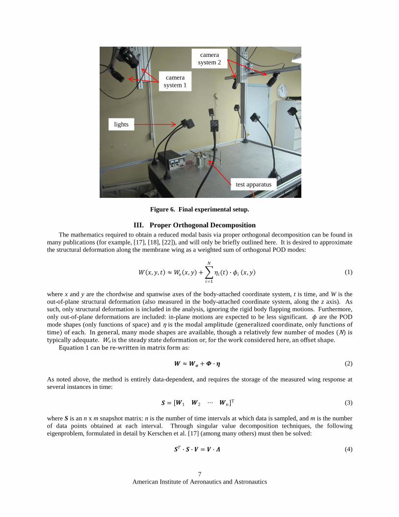
In order to capture the three-dimensional features and deformation of an elastic flapping wing, two pairs of synchronized cameras, each looking from a different viewing angle, are installed above the test apparatus, as seen in Figure 6. As the cameras must remain stationary through the experiment (to preserve the information garnered from the calibration procedure), a mounting bracket is constructed to straddle the test bench, and prevent the transmission of vibration. Seven continuous 250 W lamps illuminate the model during the test. The two heads of camera system 1 are focused primarily on the top portion of the stroke while the two heads of camera system 2 are focused primarily on the bottom portion of the stroke. Each camera system is calibrated separately, and a reference picture for each system is taken of the still wing at mid-plane. The high-speed data from each system must be stitched together, in time, to form an entire seamless flapping stroke. Testing is done using two pairs of Photron MC2 high speed digital cameras: images are taken at 2000 frames per second (fps), with a pixel resolution of 512x512, and a shutter speed of 1/16,000 s. A subset size of 21 pixels is used for image correlation, and data (namely the x, y, and z position of the reference configuration, as well as the u, v, and w displacements) is extracted along the wing every 3 pixels. More information pertaining to the use of VIC for thin membrane wings is given by Stanford et al. [25].
D. Experimental Procedure The experimental procedure is as follows: first, each of the camera systems is calibrated separately, as described
above. Images of a known, flat object are then taken with each camera, for the stitching process. The wing is then attached to the mechanism, set at the mid-stroke position, and image sets are taken with both camera pairs to serve as a reference image. High-speed images are then captured of the flapping wing at the desired frequencies (measured with a strobe light), with and without the flat plate. The appropriate images are then deleted from the data set: for example, if camera system 1 is used to capture the top portion of the flapping stroke, the images taken of the bottom portion of the stroke (typically too unfocused and skewed to be processed) with system 1 are deleted. Using the image taken of the known, flat object, a transformation matrix and displacement vector can be obtained to transform the reference image taken with system 2 to coincide with system 1, thereby stitching the two systems together in time. Finally, having processed each image through the image correlation system, the displacements captured at each time step are decomposed into rigid body flapping motions and structural deformations. This is done by obtaining a body-attached coordinate system located within the nominally-rigid cardboard portion of the wing (Figure 5), which, ideally, travels and rotates with the wing. The displacements measured within this frame will reflect structural deformations.
1 2 1 2
American Institute of Aeronautics and Astronautics
7
Figure 6. Final experimental setup.
III. Proper Orthogonal Decomposition The mathematics required to obtain a reduced modal basis via proper orthogonal decomposition can be found in
many publications (for example, [17], [18], [22]), and will only be briefly outlined here. It is desired to approximate the structural deformation along the membrane wing as a weighted sum of orthogonal POD modes:
𝑊𝑊(𝑥𝑥, 𝑦𝑦, 𝑡𝑡) ≈ 𝑊𝑊𝑜𝑜(𝑥𝑥, 𝑦𝑦) + �𝜂𝜂𝑖𝑖(𝑡𝑡) ∙ 𝜙𝜙𝑖𝑖
𝑁𝑁
𝑖𝑖=1
(𝑥𝑥, 𝑦𝑦) (1)
where x and y are the chordwise and spanwise axes of the body-attached coordinate system, t is time, and W is the out-of-plane structural deformation (also measured in the body-attached coordinate system, along the z axis). As such, only structural deformation is included in the analysis, ignoring the rigid body flapping motions. Furthermore, only out-of-plane deformations are included: in-plane motions are expected to be less significant. 𝜙𝜙 are the POD mode shapes (only functions of space) and η is the modal amplitude (generalized coordinate, only functions of time) of each. In general, many mode shapes are available, though a relatively few number of modes (N) is typically adequate. Wo is the steady state deformation or, for the work considered here, an offset shape.
Equation 1 can be re-written in matrix form as: 𝑾𝑾 ≈𝑾𝑾𝒐𝒐 + 𝜱𝜱 ∙ 𝜼𝜼 (2)
As noted above, the method is entirely data-dependent, and requires the storage of the measured wing response at several instances in time:
𝑺𝑺 = [𝑾𝑾1 𝑾𝑾2 ⋯ 𝑾𝑾n ]T (3)
where S is an n x m snapshot matrix: n is the number of time intervals at which data is sampled, and m is the number of data points obtained at each interval. Through singular value decomposition techniques, the following eigenproblem, formulated in detail by Kerschen et al. [17] (among many others) must then be solved: 𝑺𝑺𝑇𝑇 ∙ 𝑺𝑺 ∙ 𝑽𝑽 = 𝑽𝑽 ∙ 𝜦𝜦 (4)
test apparatus
lights
camera system 1
camera system 2

American Institute of Aeronautics and Astronautics
8
The eigenvectors of the system are contained in the matrix V, and the eigenvalues are given in the diagonal matrix Λ. The reduced basis is then computed as: 𝜱𝜱 = 𝑺𝑺 ∙ 𝑽𝑽 (5)
Upon solution of this eigenvalue problem, a large number of basis functions are available, but a relatively small number (N) can be utilized in practice. A suitable retention number can be inferred from the relative size of the eigenvalues Λ, which provide a measure of the system energy captured by each mode. As the number of retained modes (N) approaches the degrees of freedom in the full system (m), Eq. 1 becomes exact. Finally, the modal amplitudes are computed as: 𝜼𝜼 = 𝜱𝜱𝑻𝑻 ∙ (𝑾𝑾−𝑾𝑾𝒐𝒐) (6)
For this work, data is sampled at 2000 Hz at a flapping frequency of up to 11 Hz, for 5 complete flapping
cycles. Data from a single flapping cycle was found to suffice for an adequate snapshot of data however, so n is at least 180. As noted above, half of each flapping cycle is captured with one system of cameras, while the other half is captured with another (Figure 6). The x-y spatial distribution of data available from each system cannot be expected to be the same, so both data sets were interpolated onto the same rectilinear grid (40 chordwise points and 80 spanwise points, for a final m value of 3200) at each time step. For instances in time where both systems are able to capture the deformation of the flapping wing (temporal overlap occurs mostly towards the midstroke of the wing), the average of the two interpolated data sets was used.
IV. Measured Deformation Results Seven snapshots of measured data are given in Figure 7 through the upstroke of wing 1, with and without the
splitter plate. The contour indicates the normalized (by the length of the wing, 92 mm) out-of-plane deformation, as measured in the body-attached coordinate system. As noted above, this system is located within the stiff triangle at the root of the wing, which is also drawn into each wing snapshot. As expected, the deformation within this triangle is approximately zero for each wing contour, while the membrane deformation is on the order of 10% of the wing length. Focusing first on the wing shapes without the plate (left side of Figure 7), it can be seen that the deformation is largely interior membrane inflation, though higher-modes are prevalent as well. Inertial forces produce strong upwards deformation at the end of the upstroke (stroke reversal), and vice-versa at the beginning of the stroke. Large deformations are also seen towards mid-stroke: inertial forces are not expected to be large in this location, indicative of the fact that the complete loading history is a complex function of both inertial and aerodynamic forces.
Wing 1 deformation with the plate is given on the right side of Figure 7. As seen in Figure 4, interactions with the plate occur most strongly at the bottom of the downstroke: accordingly, the deformation of the top four snapshots is not strongly dissimilar between the cases with and without the plate. At the bottom of the downstroke (where the wing is in direct contact with the plate), the deformation of the carbon fiber perimeter of the wing is nearly zero, taking the shape of the plate itself. The membrane is bonded to the top of this carbon fiber structure, and deforms downward slightly, also making contact with the plate. As the wing pulls away from the plate, the “peeling” motion is clearly seen: the leading edge pulls away first, with a strong downward deflection of the trailing edge, similar to the motions captured in Figure 3. Wing torsion occurs largely around the leading edge, as this is the axis about which the wing is attached to the mechanism (Figure 5). A downward suction of the interior membrane is also seen in this snapshot, and continues into the next snapshot as well, after which deformation is similar to the case without the plate.
Similar data is given in Figure 8 for wing 2: as expected, the predominate mode of deformation for this case is a deflection of the trailing edge (wing twist), with some local membrane inflation in between the carbon fiber battens. Without the plate, large twisting deflections are seen at stroke reversal, as before, presumably due to inertial forces. Interestingly, as the wing travels through the midstroke (where the aerodynamic forces are expected to be large and negative), the deformation is still positive, suggesting a complex phase relationship between the internal structural forces and the external loading. For experiments with the plate included (right side of Figure 8), the wing again takes the flat shape of the plate at the bottom of the downstroke (clap), followed by a very strong peeling (twisting) motion, where the trailing edge deflects to 17% of the wing length. Unlike the deformation history of wing 1 with the plate (Figure 7), the peeling motion of wing 2 is strong enough to alter the deformation throughout the remainder of the stroke as well. Notably, the wing twist at the end of the upstroke is larger with the plate in place, suggesting a transfer of energy originating with the plate impact, as noted by Ellington [10].

American Institute of Aeronautics and Astronautics
9
Figure 7. Normalized wing 1 deformation contours (W/L) at 7 snapshots through the upstroke at 11 Hz.
Figure 8. Normalized wing 2 deformation contours (W/L) at 7 snapshots through the upstroke at 11 Hz.
The measured flapping angle is given in Figure 9 as a function of time. The experimental setup detailed above provides no method of measuring this angle except through image correlation. As such, it can be estimated from the coordinate transformation between a fixed inertial frame and the body-attached system which travels and rotates
American Institute of Aeronautics and Astronautics
10
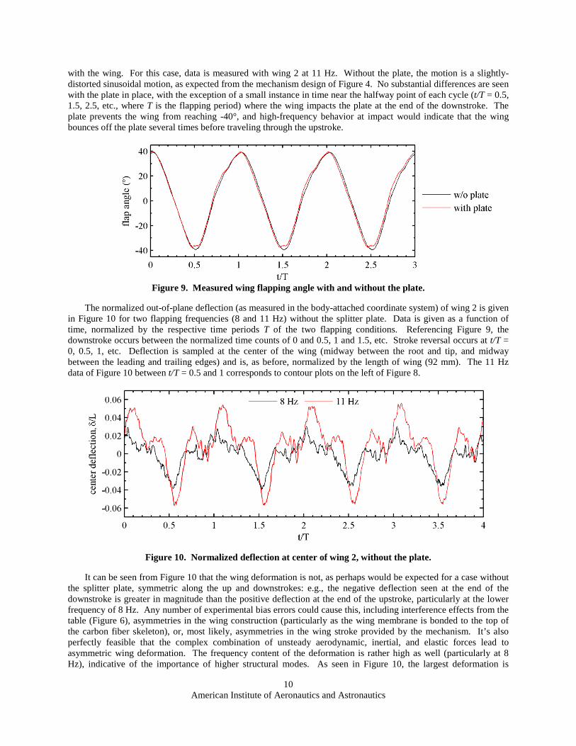
with the wing. For this case, data is measured with wing 2 at 11 Hz. Without the plate, the motion is a slightly-distorted sinusoidal motion, as expected from the mechanism design of Figure 4. No substantial differences are seen with the plate in place, with the exception of a small instance in time near the halfway point of each cycle (t/T = 0.5, 1.5, 2.5, etc., where T is the flapping period) where the wing impacts the plate at the end of the downstroke. The plate prevents the wing from reaching -40°, and high-frequency behavior at impact would indicate that the wing bounces off the plate several times before traveling through the upstroke.
Figure 9. Measured wing flapping angle with and without the plate.
The normalized out-of-plane deflection (as measured in the body-attached coordinate system) of wing 2 is given in Figure 10 for two flapping frequencies (8 and 11 Hz) without the splitter plate. Data is given as a function of time, normalized by the respective time periods T of the two flapping conditions. Referencing Figure 9, the downstroke occurs between the normalized time counts of 0 and 0.5, 1 and 1.5, etc. Stroke reversal occurs at t/T = 0, 0.5, 1, etc. Deflection is sampled at the center of the wing (midway between the root and tip, and midway between the leading and trailing edges) and is, as before, normalized by the length of wing (92 mm). The 11 Hz data of Figure 10 between t/T = 0.5 and 1 corresponds to contour plots on the left of Figure 8.
Figure 10. Normalized deflection at center of wing 2, without the plate.
It can be seen from Figure 10 that the wing deformation is not, as perhaps would be expected for a case without the splitter plate, symmetric along the up and downstrokes: e.g., the negative deflection seen at the end of the downstroke is greater in magnitude than the positive deflection at the end of the upstroke, particularly at the lower frequency of 8 Hz. Any number of experimental bias errors could cause this, including interference effects from the table (Figure 6), asymmetries in the wing construction (particularly as the wing membrane is bonded to the top of the carbon fiber skeleton), or, most likely, asymmetries in the wing stroke provided by the mechanism. It’s also perfectly feasible that the complex combination of unsteady aerodynamic, inertial, and elastic forces lead to asymmetric wing deformation. The frequency content of the deformation is rather high as well (particularly at 8 Hz), indicative of the importance of higher structural modes. As seen in Figure 10, the largest deformation is
American Institute of Aeronautics and Astronautics
11
slightly aft of the stroke reversal points (inertial snap). Positive deformation is noted at the mid-point of the upstroke (t/T = 0.75) before being pushed back down at t/T = 0.8 (presumably due to aerodynamic forces); the opposite effect is observed through the downstroke.
Forces generally increase with the square of the flapping frequency: 11 Hz should provide roughly twice the external loading seen at 8 Hz, which is evident in the deformational response of Figure 10. The qualitative temporal features of the deflection history are largely preserved (though scaled) when moving from 8 to 11 Hz, with a slight phase lag and less frequency content. This latter observation may be simply due to the fact that fewer samples per flapping period are available at 11 Hz, however. Finally, the wing deformation is fairly repeatable from cycle to cycle; not exactly periodic, but the same intrinsic temporal features (in Figure 10 and the results given below) are repeated in each cycle shown.
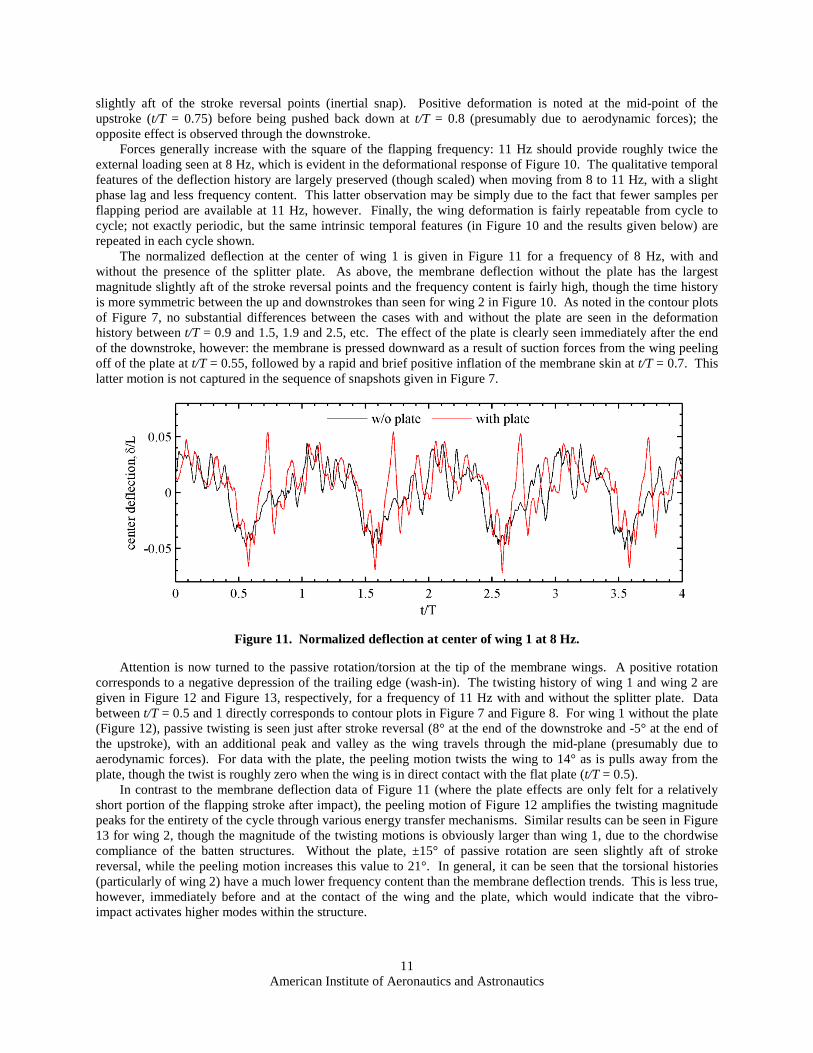
The normalized deflection at the center of wing 1 is given in Figure 11 for a frequency of 8 Hz, with and without the presence of the splitter plate. As above, the membrane deflection without the plate has the largest magnitude slightly aft of the stroke reversal points and the frequency content is fairly high, though the time history is more symmetric between the up and downstrokes than seen for wing 2 in Figure 10. As noted in the contour plots of Figure 7, no substantial differences between the cases with and without the plate are seen in the deformation history between t/T = 0.9 and 1.5, 1.9 and 2.5, etc. The effect of the plate is clearly seen immediately after the end of the downstroke, however: the membrane is pressed downward as a result of suction forces from the wing peeling off of the plate at t/T = 0.55, followed by a rapid and brief positive inflation of the membrane skin at t/T = 0.7. This latter motion is not captured in the sequence of snapshots given in Figure 7.
Figure 11. Normalized deflection at center of wing 1 at 8 Hz.
Attention is now turned to the passive rotation/torsion at the tip of the membrane wings. A positive rotation corresponds to a negative depression of the trailing edge (wash-in). The twisting history of wing 1 and wing 2 are given in Figure 12 and Figure 13, respectively, for a frequency of 11 Hz with and without the splitter plate. Data between t/T = 0.5 and 1 directly corresponds to contour plots in Figure 7 and Figure 8. For wing 1 without the plate (Figure 12), passive twisting is seen just after stroke reversal (8° at the end of the downstroke and -5° at the end of the upstroke), with an additional peak and valley as the wing travels through the mid-plane (presumably due to aerodynamic forces). For data with the plate, the peeling motion twists the wing to 14° as is pulls away from the plate, though the twist is roughly zero when the wing is in direct contact with the flat plate (t/T = 0.5).
In contrast to the membrane deflection data of Figure 11 (where the plate effects are only felt for a relatively short portion of the flapping stroke after impact), the peeling motion of Figure 12 amplifies the twisting magnitude peaks for the entirety of the cycle through various energy transfer mechanisms. Similar results can be seen in Figure 13 for wing 2, though the magnitude of the twisting motions is obviously larger than wing 1, due to the chordwise compliance of the batten structures. Without the plate, ±15° of passive rotation are seen slightly aft of stroke reversal, while the peeling motion increases this value to 21°. In general, it can be seen that the torsional histories (particularly of wing 2) have a much lower frequency content than the membrane deflection trends. This is less true, however, immediately before and at the contact of the wing and the plate, which would indicate that the vibro-impact activates higher modes within the structure.

American Institute of Aeronautics and Astronautics
12
Figure 12. Geometric twist at the tip of wing 1 at 11 Hz.
Figure 13. Geometric twist at the tip of wing 2 at 11 Hz.
V. POD Results Using the procedure described in Section III, the above data is assembled into a snapshot matrix S in order to
compute the POD modes via the eigenproblem of Eqs. 4 and 5. The first 8 POD modes for wing 1 are given in Figure 14 for flapping at 11 Hz, with (bottom row) and without (top row) the splitter plate. The amplitude of each mode shape is meaningless in the context of Figure 14, only the relative motion of disparate portions of the wing is of interest. For each shape, the deflection of the cardboard area within the triangle at the wing root is nearly zero, as expected. Invariably, the POD modes bear a striking resemblance to linear vibration modes. Numerically, it can be shown that under certain criteria (the foremost of which is a linear structural response: the membrane wing deformation seen above almost certainly has strong geometric, and possibly material, nonlinearities [25]), the two sets of bases will coincide [26]. In reality, particularly at higher mode numbers, similarities between POD modes and linear eigenvectors will become weaker; the POD modes begin to describe the patterns that develop throughout the wing as energy is divided among the periodic sets within the system [17].
The first POD mode of wing 1 without the plate (Figure 14) is a combination of positive membrane inflation and a mild amount of negative wing twist. This is a very similar deformation mode to that seen at stroke reversal of Figure 7. Presumably, the high-deformation lobe of mode 1 is shifted towards the trailing edge due to the passive wing twisting: the wing is attached to the mechanism at the leading edge. If it were attached at the mid-chord, one would expect the lobe to be centered within the wing. Mode 2 shows out-of-phase deformation mechanisms, with positive inflation occurring concurrently with positive wing twist (due to a depression at the trailing edge). The third mode has two interior deformation lobes as well as a spanwise bending mechanism, and so on for increasing mode numbers, as would also be expected for increasing linear vibration modes of a simply supported rectangular membrane. The first POD mode gathered from data with the plate is very similar to that computed without the plate.

American Institute of Aeronautics and Astronautics
13
The deformation lobe is slightly closer to the trailing edge, which is expected: the peeling motion induces more torsion in the wing, as seen in Figure 12. Modes 2, 3, and 4 bear qualitative similarities to the modes computed without the plate, though the higher modes (and admittedly less important, as will be seen below) have differences. The overall level of resemblance between the two cases is encouraging from a real-time POD-based estimation standpoint, as the use of POD modes for physical situations other than which they were created remains problematic [18].
Figure 14. POD mode shapes computed from wing 1 data at 11 Hz.
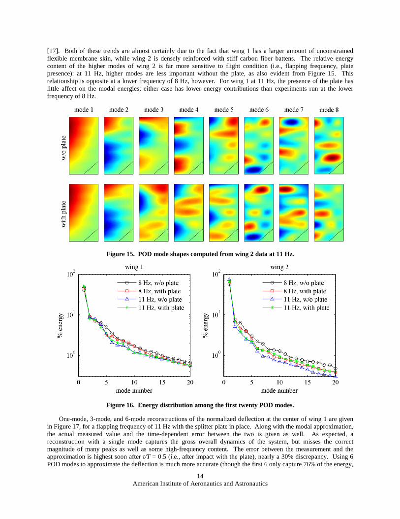
Similar data is given in Figure 15, in terms of the first 8 POD modes computed from wing 2 data, with and without the plate. The first dominant POD mode is very similar to the deformation seen at stroke reversal in Figure 8: peak deflection towards the trailing edge of the wing tip with minimal motion of the stiff carbon fiber leading edge, resulting in an overall twisting motion of the membrane. A slight undulation of the first POD mode shape contours as one moves from the root to the tip is indicative of a minor local inflation of the membrane skin in between each batten. As before, higher POD modes show an increase in the number of spatial lobes, largely concentrated at the trailing edge for the first four shapes. For higher mode numbers however (5-8), the pockets of high local deformation move towards the leading edge, found in the membrane skin in between each batten. When data with the splitter plate is used to compute the POD modes (bottom row of Figure 15) the first four modes are again very similar to modes without the plate, though it can be seen than the spatial complexity of the mode shapes increases at a faster rate for the former case. Modes 3 and 4 with the plate, for example, are much more complex than the corresponding modes without the plate, with a significant level of interior membrane deformation in addition to the energy located at the trailing edge.
As discussed above, each snapshot of data is obtained on a spatial 40 x 80 grid, and so 3200 mode shapes are available from the singular value decomposition eigenproblem (Eq. 5). Far fewer are needed in practice; a suitable retention number can be inferred from the relative size of the eigenvalues Λ (singular values), which provide a measure of the system energy (though not a true “energy” in the mechanical context [26]) captured by each mode. Those with the eight highest singular values are given, in descending order, in Figure 14 and Figure 15. Figure 16 gives the energy of the first twenty modes, expressed as a percentage of the total energy available in the system [23], for both wings under various flapping conditions. In all cases, it can be clearly seen that the first mode is very dominant, capturing up to 70% of the total energy, while the next closest is less than 10%. These energy trends would clearly indicate that the membrane wing deformation, as complex as it would seem from Figure 7 to Figure 13, has an adequate low-dimensional description.
Wing 1 converges, with mode number, at a slower rate than wing 2, and the energy associated with the first mode is lower: there is a more pronounced “energy transfer” from the first mode to the lower modes for wing 1. The muted importance of higher wing 2 modes is also seen in Figure 13, for example, where the tip twist is much cleaner, smoother, and has a lower overall harmonic content than seen for wing 1 in Figure 12. A strong energy transfer is also a well-known result of significant nonlinearities in the physical process captured by the POD modes
American Institute of Aeronautics and Astronautics
14
[17]. Both of these trends are almost certainly due to the fact that wing 1 has a larger amount of unconstrained flexible membrane skin, while wing 2 is densely reinforced with stiff carbon fiber battens. The relative energy content of the higher modes of wing 2 is far more sensitive to flight condition (i.e., flapping frequency, plate presence): at 11 Hz, higher modes are less important without the plate, as also evident from Figure 15. This relationship is opposite at a lower frequency of 8 Hz, however. For wing 1 at 11 Hz, the presence of the plate has little affect on the modal energies; either case has lower energy contributions than experiments run at the lower frequency of 8 Hz.
Figure 15. POD mode shapes computed from wing 2 data at 11 Hz.
Figure 16. Energy distribution among the first twenty POD modes.
One-mode, 3-mode, and 6-mode reconstructions of the normalized deflection at the center of wing 1 are given in Figure 17, for a flapping frequency of 11 Hz with the splitter plate in place. Along with the modal approximation, the actual measured value and the time-dependent error between the two is given as well. As expected, a reconstruction with a single mode captures the gross overall dynamics of the system, but misses the correct magnitude of many peaks as well as some high-frequency content. The error between the measurement and the approximation is highest soon after t/T = 0.5 (i.e., after impact with the plate), nearly a 30% discrepancy. Using 6 POD modes to approximate the deflection is much more accurate (though the first 6 only capture 76% of the energy,

American Institute of Aeronautics and Astronautics
15
well below the 99% value frequently cited [18]). It should be noted that the deflection at the center of the membrane skin of wing 1 is a relatively “easy” case for POD reconstruction, as this quantity is fairly large and strongly embedded in the first POD mode.
Figure 17. Modal reconstruction of the normalized deflection at center of wing 1 at 11 Hz, with the plate.
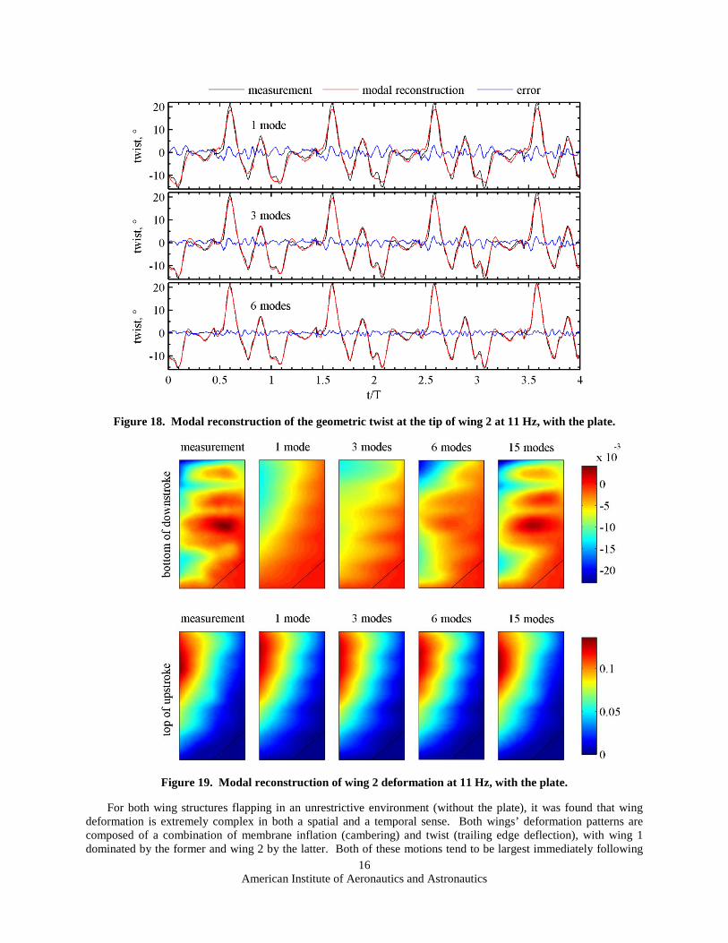
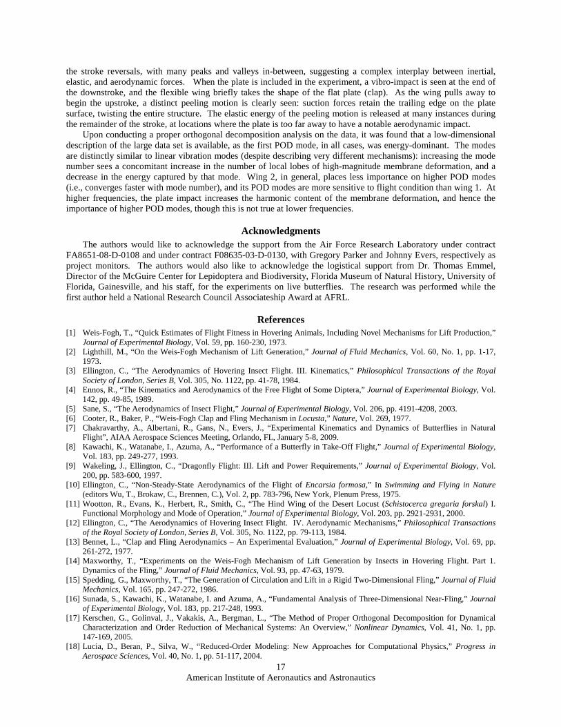
Similar data is given in Figure 18, for the geometric twist of wing 2 at 11 Hz, with the plate. As before, the wing twist is fairly large and heavily embedded in the dominant first POD mode: a single-mode reconstruction is fairly accurate, but under-predicts the magnitude of many peaks. Most notably, a double peak at the end of the upstroke (t/T = 1, 2, etc.) is completely missed, and requires at least the first 3 POD modes for an accurate representation. With 6 POD modes, the reconstruction is fairly accurate, though relatively large errors are seen at t/T = 0.5, 1.5, etc., as the wing makes contact with the plate and the wing twist becomes zero. This is further explored in Figure 19, where various modal reconstructions are compared against the measured full-field wing deformation. This is done for wing 2, at two locations within the stroke: the first instant of contact with the plate (top row), and stroke reversal at the end of the upstroke (bottom row). As also seen in Figure 19, modal convergence is very slow at the moment of impact, particularly as the first dominant mode shape is distinctly different than the measured shape. Nearly 15 modes are needed for an accurate reconstruction, which is in sharp contrast with the modal convergence at the end of the upstroke, which is very rapid.
VI. Conclusion This paper has detailed efforts towards an experimental characterization of a flapping membrane wing
undergoing a clap-fling operation. Full-field deformation of the unsteady structural dynamics are obtained with the use of a high-speed non-contact visual image correlation system, while the clap-fling mechanism is approximated with a single wing, by replacing the symmetry plane between two wings with a splitter plate simulating the pair wing. Data is taken with two distinctly different membrane wing structures, the first of which is a membrane skin clamped along its perimeter to a carbon fiber frame. The second structure is a membrane skin with a series of chordwise battens. Finally, the obtained data is used to compute POD modes of the system, with the hope that a low-dimensional rendering of the complex physics inherent within the flapping wing can help elucidate crucial mechanisms and relationships.
American Institute of Aeronautics and Astronautics
16
Figure 18. Modal reconstruction of the geometric twist at the tip of wing 2 at 11 Hz, with the plate.
Figure 19. Modal reconstruction of wing 2 deformation at 11 Hz, with the plate.
For both wing structures flapping in an unrestrictive environment (without the plate), it was found that wing deformation is extremely complex in both a spatial and a temporal sense. Both wings’ deformation patterns are composed of a combination of membrane inflation (cambering) and twist (trailing edge deflection), with wing 1 dominated by the former and wing 2 by the latter. Both of these motions tend to be largest immediately following
American Institute of Aeronautics and Astronautics
17
the stroke reversals, with many peaks and valleys in-between, suggesting a complex interplay between inertial, elastic, and aerodynamic forces. When the plate is included in the experiment, a vibro-impact is seen at the end of the downstroke, and the flexible wing briefly takes the shape of the flat plate (clap). As the wing pulls away to begin the upstroke, a distinct peeling motion is clearly seen: suction forces retain the trailing edge on the plate surface, twisting the entire structure. The elastic energy of the peeling motion is released at many instances during the remainder of the stroke, at locations where the plate is too far away to have a notable aerodynamic impact.
Upon conducting a proper orthogonal decomposition analysis on the data, it was found that a low-dimensional description of the large data set is available, as the first POD mode, in all cases, was energy-dominant. The modes are distinctly similar to linear vibration modes (despite describing very different mechanisms): increasing the mode number sees a concomitant increase in the number of local lobes of high-magnitude membrane deformation, and a decrease in the energy captured by that mode. Wing 2, in general, places less importance on higher POD modes (i.e., converges faster with mode number), and its POD modes are more sensitive to flight condition than wing 1. At higher frequencies, the plate impact increases the harmonic content of the membrane deformation, and hence the importance of higher POD modes, though this is not true at lower frequencies.
Acknowledgments The authors would like to acknowledge the support from the Air Force Research Laboratory under contract
FA8651-08-D-0108 and under contract F08635-03-D-0130, with Gregory Parker and Johnny Evers, respectively as project monitors. The authors would also like to acknowledge the logistical support from Dr. Thomas Emmel, Director of the McGuire Center for Lepidoptera and Biodiversity, Florida Museum of Natural History, University of Florida, Gainesville, and his staff, for the experiments on live butterflies. The research was performed while the first author held a National Research Council Associateship Award at AFRL.
References [1] Weis-Fogh, T., “Quick Estimates of Flight Fitness in Hovering Animals, Including Novel Mechanisms for Lift Production,”
Journal of Experimental Biology, Vol. 59, pp. 160-230, 1973. [2] Lighthill, M., “On the Weis-Fogh Mechanism of Lift Generation,” Journal of Fluid Mechanics, Vol. 60, No. 1, pp. 1-17,
1973. [3] Ellington, C., “The Aerodynamics of Hovering Insect Flight. III. Kinematics,” Philosophical Transactions of the Royal
Society of London, Series B, Vol. 305, No. 1122, pp. 41-78, 1984. [4] Ennos, R., “The Kinematics and Aerodynamics of the Free Flight of Some Diptera,” Journal of Experimental Biology, Vol.
142, pp. 49-85, 1989. [5] Sane, S., “The Aerodynamics of Insect Flight,” Journal of Experimental Biology, Vol. 206, pp. 4191-4208, 2003. [6] Cooter, R., Baker, P., “Weis-Fogh Clap and Fling Mechanism in Locusta,” Nature, Vol. 269, 1977. [7] Chakravarthy, A., Albertani, R., Gans, N., Evers, J., “Experimental Kinematics and Dynamics of Butterflies in Natural
Flight”, AIAA Aerospace Sciences Meeting, Orlando, FL, January 5-8, 2009. [8] Kawachi, K., Watanabe, I., Azuma, A., “Performance of a Butterfly in Take-Off Flight,” Journal of Experimental Biology,
Vol. 183, pp. 249-277, 1993. [9] Wakeling, J., Ellington, C., “Dragonfly Flight: III. Lift and Power Requirements,” Journal of Experimental Biology, Vol.
200, pp. 583-600, 1997. [10] Ellington, C., “Non-Steady-State Aerodynamics of the Flight of Encarsia formosa,” In Swimming and Flying in Nature
(editors Wu, T., Brokaw, C., Brennen, C.), Vol. 2, pp. 783-796, New York, Plenum Press, 1975. [11] Wootton, R., Evans, K., Herbert, R., Smith, C., “The Hind Wing of the Desert Locust (Schistocerca gregaria forskal) I.
Functional Morphology and Mode of Operation,” Journal of Experimental Biology, Vol. 203, pp. 2921-2931, 2000. [12] Ellington, C., “The Aerodynamics of Hovering Insect Flight. IV. Aerodynamic Mechanisms,” Philosophical Transactions
of the Royal Society of London, Series B, Vol. 305, No. 1122, pp. 79-113, 1984. [13] Bennet, L., “Clap and Fling Aerodynamics – An Experimental Evaluation,” Journal of Experimental Biology, Vol. 69, pp.
261-272, 1977. [14] Maxworthy, T., “Experiments on the Weis-Fogh Mechanism of Lift Generation by Insects in Hovering Flight. Part 1.
Dynamics of the Fling,” Journal of Fluid Mechanics, Vol. 93, pp. 47-63, 1979. [15] Spedding, G., Maxworthy, T., “The Generation of Circulation and Lift in a Rigid Two-Dimensional Fling,” Journal of Fluid
Mechanics, Vol. 165, pp. 247-272, 1986. [16] Sunada, S., Kawachi, K., Watanabe, I. and Azuma, A., “Fundamental Analysis of Three-Dimensional Near-Fling,” Journal
of Experimental Biology, Vol. 183, pp. 217-248, 1993. [17] Kerschen, G., Golinval, J., Vakakis, A., Bergman, L., “The Method of Proper Orthogonal Decomposition for Dynamical
Characterization and Order Reduction of Mechanical Systems: An Overview,” Nonlinear Dynamics, Vol. 41, No. 1, pp. 147-169, 2005.
[18] Lucia, D., Beran, P., Silva, W., “Reduced-Order Modeling: New Approaches for Computational Physics,” Progress in Aerospace Sciences, Vol. 40, No. 1, pp. 51-117, 2004.
American Institute of Aeronautics and Astronautics
18
[19] Ravindran, S., “A Reduced-Order Approach for Optimal Control of Fluids Using Proper Orthogonal Decomposition,” International Journal for Numerical Methods in Fluids, Vol. 34, No. 5, pp. 425-448, 2000.
[20] Bozkurttas, M., Dong, H., Mittal, R., Madden, P., Lauder, G., “Hydrodynamic Performance of Deformable Fish Fins and Flapping Foils,” AIAA Aerospace Sciences Meeting and Exhibit, Reno, NV, January 9-12, 2006.
[21] Pivkin, I., “Visualization and Interpretation of the Proper Orthogonal Decomposition of Bat Wing Kinematics,” Masters Thesis, Department of Computer Science, Brown University, Providence, RI, 2006.
[22] Stanford, B., Beran, P., “Cost Reduction Techniques for the Structural Design of Nonlinear Flapping Wings,” AIAA Structures, Structural Dynamics, and Materials Conference, Palm Springs, CA, May 4-7, 2009.
[23] Lian, Y., Shyy, W., Viieru, D., Zhang, B., “Membrane Wing Aerodynamics for Micro Air Vehicles,” Progress in Aerospace Sciences, Vol. 39, pp. 425-465, 2003.
[24] Schmit, R., Glauser, M., “Use of Low-Dimensional Methods for Wake Flowfield Estimation from Dynamic Strain,” AIAA Journal, Vol. 43, pp. 1133-1136, 2005.
[25] Stanford, B., Ifju, P., Albertani, R., Shyy, W., “Fixed Membrane Wings for Micro Air Vehicles: Experimental Characterization, Numerical Modeling, and Tailoring,” Progress in Aerospace Sciences, Vol. 44, No. 4, pp. 258-294, 2008.
[26] Feeny, B., Kappagantu, R., “On the Physical Interpretation of Proper Orthogonal Modes in Vibration,” Journal of Sound and Vibration, Vol. 211, No. 4, pp. 607-616, 1998.