Propeller Backpack (#28327): Video Terminal and … © Parallax Inc. Propeller Backpack (#28327)...
26
Web Site: www.parallax.com Forums: forums.parallax.com Sales: [email protected] Technical: [email protected] Office: (916) 624-8333 Fax: (916) 624-8003 Sales: (888) 512-1024 Tech Support: (888) 997-8267 Copyright © Parallax Inc. Propeller Backpack (#28327) v1.0 11/3/2009 Page 1 of 26 Propeller Backpack (#28327): Video Terminal and A/V-enhanced Propeller Development Module General Description The Propeller Backpack is a compact, multipurpose Propeller-based module that is optimized for audio and video applications. It is preprogrammed as an NTSC video character display for your BASIC Stamp ® (or other compatible controller). This module is also a fully capable Propeller ™ microcontroller development platform, which you can program with Parallax’s free “Propeller Tool” software. For expansion, it includes a socket to accommodate a daughterboard from Parallax’s growing assortment of MoBo accessories. Features and Specifications • Compact size: 1.5 x 1.35 in. (38.1 x 34.3 mm) • Propeller P8X32A-Q44 chip and 10 MHz crystal for up to 80 MHz operation • Sigma-delta analog input circuitry (2 channels) • Onboard circuitry for video out, video sync in, video overlay switching, audio I/O, and push-to-talk (PTT) • Double-size (64K x 8) EEPROM for programs and data • External interface: 1/8” stereo phone jack for line-level A/V and PTT signals, 3-pin servo header for power and serial I/O, 4-pin Prop Plug header, 12-position daughterboard socket • Power requirements: 4–6 V unregulated DC @ 20–150 mA, depending on application (5 V regulated DC is required when used with daughterboards.) Applications • Serial video terminal for BASIC Stamp • Video character overlay (e.g. for GPS coordinates) • Speech output • Audio special effects • Machine vision (with optional daughterboard) Out of the Box What’s Included Propeller Backpack Module with Screws, Standoffs, and Jumpers Installed.
-
Upload
vuonghuong -
Category
Documents
-
view
217 -
download
1
Transcript of Propeller Backpack (#28327): Video Terminal and … © Parallax Inc. Propeller Backpack (#28327)...

Web Site: www.parallax.com Forums: forums.parallax.com Sales: [email protected] Technical: [email protected]
Office: (916) 624-8333 Fax: (916) 624-8003 Sales: (888) 512-1024 Tech Support: (888) 997-8267
Copyright © Parallax Inc. Propeller Backpack (#28327) v1.0 11/3/2009 Page 1 of 26
Propeller Backpack (#28327): Video Terminal and A/V-enhanced Propeller Development Module
General Description
The Propeller Backpack is a compact, multipurpose Propeller-based module that is optimized for audio and video applications. It is preprogrammed as an NTSC video character display for your BASIC Stamp® (or other compatible controller).
This module is also a fully capable Propeller™ microcontroller development platform, which you can program with Parallax’s free “Propeller Tool” software. For expansion, it includes a socket to accommodate a daughterboard from Parallax’s growing assortment of MoBo accessories.
Features and Specifications
• Compact size: 1.5 x 1.35 in. (38.1 x 34.3 mm)
• Propeller P8X32A-Q44 chip and 10 MHz crystal for up to 80 MHz operation
• Sigma-delta analog input circuitry (2 channels)
• Onboard circuitry for video out, video sync in, video overlay switching, audio I/O, and push-to-talk (PTT)
• Double-size (64K x 8) EEPROM for programs and data
• External interface: 1/8” stereo phone jack for line-level A/V and PTT signals, 3-pin servo header for power and serial I/O, 4-pin Prop Plug header, 12-position daughterboard socket
• Power requirements: 4–6 V unregulated DC @ 20–150 mA, depending on application (5 V regulated DC is required when used with daughterboards.)
Applications
• Serial video terminal for BASIC Stamp • Video character overlay (e.g. for GPS coordinates) • Speech output • Audio special effects • Machine vision (with optional daughterboard)
Out of the Box
What’s Included
Propeller Backpack Module with Screws, Standoffs, and Jumpers Installed.
Copyright © Parallax Inc. Propeller Backpack (#28327) v1.0 11/3/2009 Page 2 of 26
What You Need to Provide
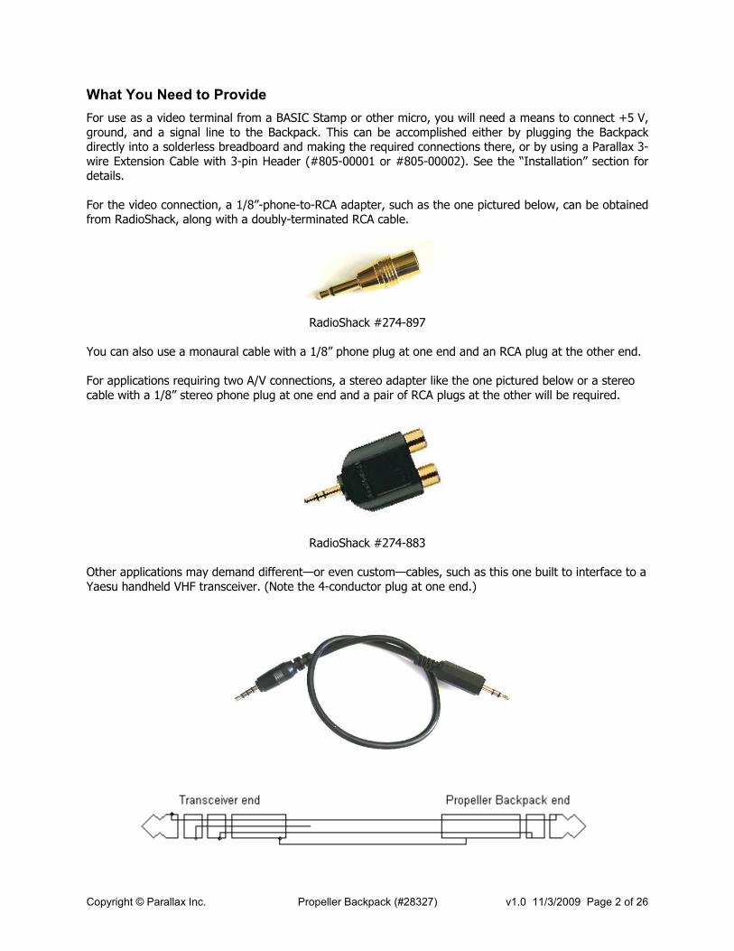
For use as a video terminal from a BASIC Stamp or other micro, you will need a means to connect +5 V, ground, and a signal line to the Backpack. This can be accomplished either by plugging the Backpack directly into a solderless breadboard and making the required connections there, or by using a Parallax 3-wire Extension Cable with 3-pin Header (#805-00001 or #805-00002). See the “Installation” section for details. For the video connection, a 1/8”-phone-to-RCA adapter, such as the one pictured below, can be obtained from RadioShack, along with a doubly-terminated RCA cable.
RadioShack #274-897
You can also use a monaural cable with a 1/8” phone plug at one end and an RCA plug at the other end. For applications requiring two A/V connections, a stereo adapter like the one pictured below or a stereo cable with a 1/8” stereo phone plug at one end and a pair of RCA plugs at the other will be required.
RadioShack #274-883
Other applications may demand different—or even custom—cables, such as this one built to interface to a Yaesu handheld VHF transceiver. (Note the 4-conductor plug at one end.)
Copyright © Parallax Inc. Propeller Backpack (#28327) v1.0 11/3/2009 Page 3 of 26
Quick Start
For a quick demo of the Propeller Backpack’s video capabilities, connect it as shown in the “Installation” section below. Also connect a video monitor or TV that has a video input (not the antenna input), using an adapter or cable like those described above. Make sure a jumper is installed on the pair of pins marked “VID.” The “OVL” jumper is not required, but you can leave it in place anyway to avoid losing it. From the Propeller Backpack product page on the Parallax website, download the program, PropBP_terminal_demo.bs2, and run it. You should see an animated demonstration which begins, "This is a demo of the Propeller Backpack TV terminal.”
Installation
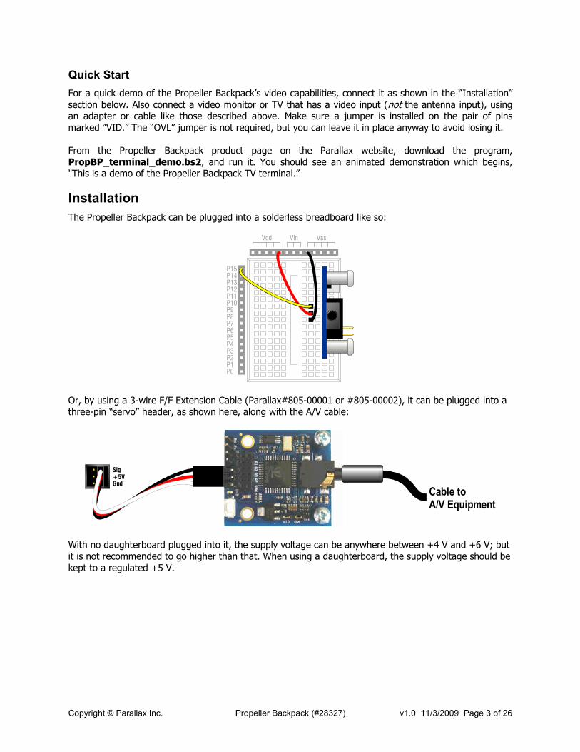
The Propeller Backpack can be plugged into a solderless breadboard like so:
Vdd Vin Vss
P15P14P13P12P11P10P9P8P7P6P5P4P3P2P1P0
Or, by using a 3-wire F/F Extension Cable (Parallax#805-00001 or #805-00002), it can be plugged into a three-pin “servo” header, as shown here, along with the A/V cable:
Sig+5VGnd
Cable toA/V Equipment
With no daughterboard plugged into it, the supply voltage can be anywhere between +4 V and +6 V; but it is not recommended to go higher than that. When using a daughterboard, the supply voltage should be kept to a regulated +5 V.

Copyright © Parallax Inc. Propeller Backpack (#28327) v1.0 11/3/2009 Page 4 of 26
Using the Pre-loaded TV Terminal Firmware
Introduction and Tutorial
As the above “Quick Start” demo shows, the Propeller Backpack can function as a video terminal driver out of the box, without requiring any Propeller programming. This feature makes it possible for a BASIC Stamp programmer to display text on an NTSC monitor in a variety of ways, without knowing anything about the Parallax Propeller. In this section, the various commands used to control the TV terminal from the BASIC Stamp are introduced tutorial-style. A subsequent section describes them in detail. NOTE: Wherever you see a constant symbol (e.g. SCRSIZ, USECLR, etc.), it refers either to one of PBASIC’s predefined DEBUG constants or to one of the constants defined in the demo program, PropBP_terminal_demo.bs2, cited above. You can copy and paste the constant block from this program into your own PBASIC code. This will make it easier to use these constants in command strings sent to the Backpack. Communication with the Backpack video terminal program takes place using serial I/O, transmitting and receiving at 9600 baud, using a non-inverted, open-drain protocol. The Backpack includes a pullup resistor to +5 V, so you do not need to apply one externally. Because of the open-drain protocol, the pin used to communicate with the Propeller Backpack should always be configured as an input, except when being driven low. The pin and baudmode settings for the BS2 on pin 15 at 9600 baud, for example, would be: io PIN 15 baud CON 84 + 32768
When your PBASIC program first starts, it is a good idea to reset the Propeller Backpack before doing anything else. You do this by pulling the serial I/O pin low for 500 ms and releasing it. Do not hold it low for more than a second, though, as this will cause the Backpack to enter “programming mode” and not start the terminal program. Here’s a typical startup sequence: LOW io 'Reset the Propeller Backpack PAUSE 500 INPUT io PAUSE 2000 'Wait for it to come out of reset.
Once the terminal firmware resets, it will be configured as follows:
Columns: 40 Rows: 13 Color: 0 (white foreground; black background) Current window: 0 Screen: cleared Cursor position: 0,0 (top left-hand corner)
Printing to the screen is as easy as sending it text. For example, to display “Hello, world!”, just send it using a SEROUT command, like this: SEROUT io, baud, ["Hello, world!"]

Copyright © Parallax Inc. Propeller Backpack (#28327) v1.0 11/3/2009 Page 5 of 26
It will display as follows:
Hello, world!
If the letters are too small, you can set a different screen size by sending the SCRSIZ command ($1D), followed by a column and row count. For example, to double the font size, just halve the default screen size, like this: SEROUT io, baud, [SCRSIZ, 20, 6, "Hello, world!"]
Now the screen will look like this instead:
Hello, world!
Whenever you change the screen size, the display resets and clears completely, and any windows or attributes (e.g. color) that you’ve set will be cleared as well. For this reason, setting the screen size is normally done only at the beginning of your program. If you get bored with white-on-black, you can change the color of your text on the fly. For example, if you wanted “world” to be black on a blue background, you could do this: SEROUT io, baud, [SCRSIZ, 20, 6, "Hello, ", USECLR, 10, "world", USECLR, 0, "!"]
This is how the screen would look (except a little blockier, since the font gets pixelated at larger scales):
Hello, !world
Copyright © Parallax Inc. Propeller Backpack (#28327) v1.0 11/3/2009 Page 6 of 26
The screen can be divided into regions, called “windows”, which you can define and write to independently. There is one predefined window (number 0), which encompasses the entire screen. When you create a new window, you define its position (left column and top row) and size (column count and row count). (Please note that column and row numbers start a location 0, not location 1.) For example, if you want a new window at location (5,5) that is 6 columns wide and 7 rows high, you’d define it thus: SEROUT io, baud, [DEFWIN, 1, 5, 5, 6, 7]
Now DEFWIN doesn’t do anything except tell the Backpack that you have a window identified as number 1, having the size and location given above. It doesn’t even let you start writing in that window. To do that, you invoke the USEWIN command: SEROUT io, baud, [USEWIN, 1]
This tells the Backpack that subsequent text is to be written in window 1. But, so far, window 1 doesn’t look any different than window 0, i.e. the entire screen. This is easily remedied by changing its color: SEROUT io, baud, [CHGCLR, 12]
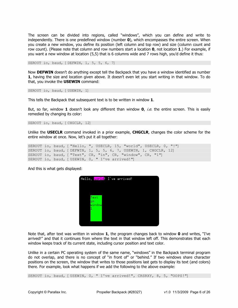
Unlike the USECLR command invoked in a prior example, CHGCLR, changes the color scheme for the entire window at once. Now, let’s put it all together: SEROUT io, baud, ["Hello, ", USECLR, 15, "world", USECLR, 0, "!"] SEROUT io, baud, [DEFWIN, 1, 5, 5, 6, 7, USEWIN, 1, CHGCLR, 12] SEROUT io, baud, ["Text", CR, "in", CR, "window", CR, "1"] SEROUT io, baud, [USEWIN, 0, " I've arrived!"]
And this is what gets displayed:
Hello, ! I've arrived! world112345678901234567890123456789012345678921234567890123456789012345678901234567893123456789012345678901234567890123456789412345678901234567890123456789012345678951234Text 1234567890123456789012345678961234in 1234567890123456789012345678971234window12345678901234567890123456789812341 1234567890123456789012345678991234 1234567890123456789012345678901234 1234567890123456789012345678911234 123456789012345678901234567892123456789012345678901234567890123456789
Note that, after text was written in window 1, the program changes back to window 0 and writes, “I’ve arrived!” and that it continues from where the text in that window left off. This demonstrates that each window keeps track of its current state, including cursor position and text color. Unlike in a certain PC operating system of the same name, “windows” in the Backpack terminal program do not overlap, and there is no concept of “in front of” or “behind.” If two windows share character positions on the screen, the window that writes to those positions last gets to display its text (and colors) there. For example, look what happens if we add the following to the above example: SEROUT io, baud, [USEWIN, 0, " I've arrived!", CRSRXY, 8, 5, "OOPS!"]

Copyright © Parallax Inc. Propeller Backpack (#28327) v1.0 11/3/2009 Page 7 of 26
Here’s the display:
Hello, ! I've arrived!
OOPS!
world112345678901234567890123456789012345678921234567890123456789012345678901234567893123456789012345678901234567890123456789412345678901234567890123456789012345678951234Tex 34567890123456789012345678961234in 1234567890123456789012345678971234window12345678901234567890123456789812341 1234567890123456789012345678991234 1234567890123456789012345678901234 1234567890123456789012345678911234 123456789012345678901234567892123456789012345678901234567890123456789
This example also shows how cursor positioning works. It’s pretty much that same as it is with the DEBUG screen, except that the coordinates are relative to the upper left-hand corner of the current window, not to the entire screen. When writing multiple lines to a window, once you get to the window’s bottom line, additional lines will cause text in the window to scroll up, just as it would on a PC screen. This program fragment, for example, defines a window, and begins writing data into it, one line at a time: SEROUT io, baud, [DEFWIN, 1, 20, 2, 7, 9, USEWIN, 1, CHGCLR, 12] FOR W0 = 1000 TO 1050 SEROUT io, baud, [" ", DEC W0, CR] NEXT
When it gets to the bottom line, the data scrolls upwards, leaving this on the screen when it has finished:
Hello, world! I've arrived!1123456789012345678901234567890123456789212345678901234567890123456789012345678931234567890123456789 1043 789012345678941234567890123456789 1044 789012345678951234TexOOPS!3456789 1045 789012345678961234in 123456789 1046 789012345678971234window123456789 1047 7890123456789812341 123456789 1048 789012345678991234 123456789 1049 789012345678901234 123456789 1050 789012345678911234 123456789 78901234567892123456789012345678901234567890123456789
Scrolling can be done explicitly, as well. For example, let’s add the following statement to the above code: SEROUT io, baud, [SCRLDN, SCRLDN, SCRLDN, SCRLRT]
Copyright © Parallax Inc. Propeller Backpack (#28327) v1.0 11/3/2009 Page 8 of 26
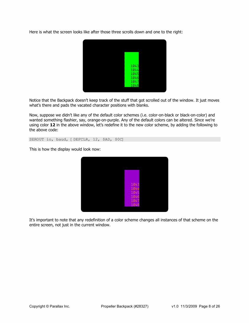
Here is what the screen looks like after those three scrolls down and one to the right:
Hello, world! I've arrived!1123456789012345678901234567890123456789212345678901234567890123456789012345678931234567890123456789 789012345678941234567890123456789 789012345678951234TexOOPS!3456789 789012345678961234in 123456789 1043789012345678971234window123456789 10447890123456789812341 123456789 1045789012345678991234 123456789 1046789012345678901234 123456789 1047789012345678911234 123456789 104878901234567892123456789012345678901234567890123456789
Notice that the Backpack doesn’t keep track of the stuff that got scrolled out of the window. It just moves what’s there and pads the vacated character positions with blanks. Now, suppose we didn’t like any of the default color schemes (i.e. color-on-black or black-on-color) and wanted something flashier, say, orange-on-purple. Any of the default colors can be altered. Since we’re using color 12 in the above window, let’s redefine it to the new color scheme, by adding the following to the above code: SEROUT io, baud, [DEFCLR, 12, $AD, $0C]
This is how the display would look now:
Hello, world! I've arrived!1123456789012345678901234567890123456789212345678901234567890123456789012345678931234567890123456789 789012345678941234567890123456789 789012345678951234TexOOPS!3456789 789012345678961234in 123456789 789012345678971234window123456789 7890123456789812341 123456789 789012345678991234 123456789 789012345678901234 123456789 789012345678911234 123456789 78901234567892123456789012345678901234567890123456789
104310441045104610471048
It’s important to note that any redefinition of a color scheme changes all instances of that scheme on the entire screen, not just in the current window.

Copyright © Parallax Inc. Propeller Backpack (#28327) v1.0 11/3/2009 Page 9 of 26
Command Definitions
In this section, each command is given with both its defined constant name and its hexadecimal value. You can use either one in your SEROUT statements. PBASIC’s predefined constant names are shown in BLACK; the Backpack’s own constants, in RED. Where the term “cursor” is used, it refers to the position where the next character will be written. There is no visible cursor on the screen, however.
CLS $00 Clear the current window.
Clear the current window, converting all character cells to the window’s background color, and home the cursor to the window’s top left-hand corner. If the current window is window 0, the entire screen will be cleared.
HOME $01 Move cursor to the current window’s home position.
This command moves the to the top left-hand corner of the current window but does not change the window’s contents.
CRSRXY, x, y $02, x, y Move cursor to position (x,y).
The two bytes following this command define the new position (column, row) of the cursor within the current window, starting from column zero, row zero in the window’s home position. The contents of the window are unchanged.
CRSRLF $03 Move cursor one column to the left.
CRSRRT $04 Move cursor one column to the right.
CRSRUP $05 Move cursor one row up.
CRSRDN $06 Move cursor one row down.
Move the cursor in the direction indicated. Motion saturates (stops) at the current window’s left, right, top, and bottom edges.
USECLR, c $07, c Change to color scheme c for the next character(s).
This command changes the color scheme to one of the 16 (numbered 0 through 15) available. Therefore, the byte c that follows USECLR must be less than or equal to 15; otherwise, the results will be unpredictable. The default color schemes are shown below.
0 White on black 8 Black on white
1 Lavender on black 9 Black on lavender
2 Blue on black 10 Black on blue
3 Aqua on black 11 Black on aqua
4 Green on black 12 Black on green
5 Yellow on black 13 Black on yellow
6 Orange on black 14 Black on orange
7 Red on black 15 Black on red
Please note that, depending upon your monitor and its brightness and contrast adjustments, the colors you see may differ slightly from those shown here. This is normal.
Copyright © Parallax Inc. Propeller Backpack (#28327) v1.0 11/3/2009 Page 10 of 26
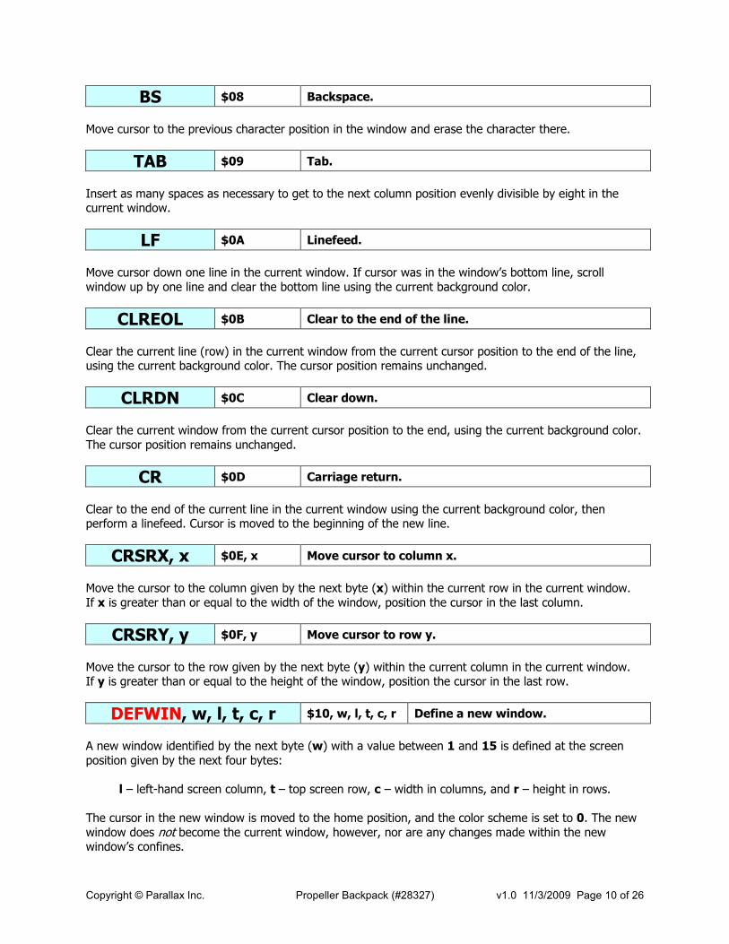
BS $08 Backspace.
Move cursor to the previous character position in the window and erase the character there.
TAB $09 Tab.
Insert as many spaces as necessary to get to the next column position evenly divisible by eight in the current window.
LF $0A Linefeed.
Move cursor down one line in the current window. If cursor was in the window’s bottom line, scroll window up by one line and clear the bottom line using the current background color.
CLREOL $0B Clear to the end of the line.
Clear the current line (row) in the current window from the current cursor position to the end of the line, using the current background color. The cursor position remains unchanged.
CLRDN $0C Clear down.
Clear the current window from the current cursor position to the end, using the current background color. The cursor position remains unchanged.
CR $0D Carriage return.
Clear to the end of the current line in the current window using the current background color, then perform a linefeed. Cursor is moved to the beginning of the new line.
CRSRX, x $0E, x Move cursor to column x.
Move the cursor to the column given by the next byte (x) within the current row in the current window. If x is greater than or equal to the width of the window, position the cursor in the last column.
CRSRY, y $0F, y Move cursor to row y.
Move the cursor to the row given by the next byte (y) within the current column in the current window. If y is greater than or equal to the height of the window, position the cursor in the last row.
DEFWIN, w, l, t, c, r $10, w, l, t, c, r Define a new window.
A new window identified by the next byte (w) with a value between 1 and 15 is defined at the screen position given by the next four bytes:
l – left-hand screen column, t – top screen row, c – width in columns, and r – height in rows.
The cursor in the new window is moved to the home position, and the color scheme is set to 0. The new window does not become the current window, however, nor are any changes made within the new window’s confines.
Copyright © Parallax Inc. Propeller Backpack (#28327) v1.0 11/3/2009 Page 11 of 26
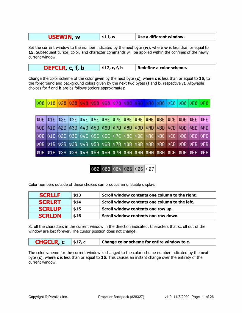
USEWIN, w $11, w Use a different window.
Set the current window to the number indicated by the next byte (w), where w is less than or equal to 15. Subsequent cursor, color, and character commands will be applied within the confines of the newly current window.
DEFCLR, c, f, b $12, c, f, b Redefine a color scheme.
Change the color scheme of the color given by the next byte (c), where c is less than or equal to 15, to the foreground and background colors given by the next two bytes (f and b, respectively). Allowable choices for f and b are as follows (colors approximate):
Color numbers outside of these choices can produce an unstable display.
SCRLLF $13 Scroll window contents one column to the right.
SCRLRT $14 Scroll window contents one column to the left.
SCRLUP $15 Scroll window contents one row up.
SCRLDN $16 Scroll window contents one row down.
Scroll the characters in the current window in the direction indicated. Characters that scroll out of the window are lost forever. The cursor position does not change.
CHGCLR, c $17, c Change color scheme for entire window to c.
The color scheme for the current window is changed to the color scheme number indicated by the next byte (c), where c is less than or equal to 15. This causes an instant change over the entirety of the current window.

Copyright © Parallax Inc. Propeller Backpack (#28327) v1.0 11/3/2009 Page 12 of 26
SCRSIZ, c, r $1D, c, r Change screen size to c columns by r rows.
The overall size of the display screen is changed according to the next two bytes (c and r), where c (the column count) is less than or equal to 40, and r (the row count) is less than or equal to 13. This indirectly affects the font size, which will be made as large as possible for the number of rows and columns selected in order to fill the display area. In extreme cases, characters can become squashed either vertically or horizontally, so some discretion is required to preserve readability. When executed, the entire screen is blanked and reinitialized. An attached monitor may briefly lose sync, causing the picture to roll. Normally SCRSIZ is used only at the beginning of one’s program.
CLRW $1E Clear the current window.
This command is identical to CLS. It’s included here so it can be used in zero-terminated strings.
ESC, c $1F, c Escape the next character.
The Propeller’s displayable character set includes characters in the range $00 to $1F, which are commands for the Backpack. The ESC command allows you to display one of these characters by forcing the Backpack to ignore any special command significance the next character might have and to display it
as-is. For example, sending ESC, $11 will cause the Greek letter pi (ππππ) to be displayed. (See character chart below.)
ZERO $FF Equals zero when used as a command argument.
When sending zero-terminated strings, you can substitute ZERO for 0 when it’s used as an argument for one of the above commands. Do not use ZERO to substitute for CLS, though; use CLRW instead.
Character $20 - $FF Clear the current window.
Any character in the range shown, when sent where a command might be expected, is displayed in the current window.
Character Chart
The following chart illustrates the characters available to display on the video screen. The shaded characters numbered between $00 and $1F must be preceded by an escape (ESC) command.
$00 - $1F
$20 - $3F
$40 - $5F
$60 - $7F
$80 - $9F
$A0 - $BF
$C0 - $DF
$E0 - $FF

Copyright © Parallax Inc. Propeller Backpack (#28327) v1.0 11/3/2009 Page 13 of 26
Loading New Firmware
For those users wishing to explore beyond the confines of the default video terminal, or those just wishing to install updates of the video terminal, there are three ways to upload new firmware:
1. Use the Propeller Tool and a Prop Plug (Parallax #32201).
2. Use the Propeller Backpack Loader program (downloadable from the Propeller Backpack product page) with a Prop Plug.
3. Use the Propeller Backpack Loader program with any member of the BASIC Stamp 2 family (no Prop Plug required).
Using the Prop Plug
If you use the Prop Plug to do your programming, just plug it into the Propeller Backpack, making sure that the TX and RX designators on the board align with those on the Prop Plug. You will still need to apply power via the three-pin header in order for programming to work.
Using the Propeller Tool
If you are using the Prop Plug, programs can be uploaded in the normal way using the Propeller Tool downloadable from the Parallax website. There is one catch, however: any programs saved to EEPROM will overwrite the monitor and bootloader firmware that comes installed on the Propeller Backpack. Until this program is reloaded via the Propeller Tool and Prop Plug, it will not be possible to use the Propeller Backpack Loader program to upload programs via a BASIC Stamp. To restore this program, follow the directions given later in this chapter.
Using the Propeller Backpack Loader
The Propeller Backpack Loader (PropBP_loader.exe), downloadable in zip format from the Propeller Backpack product page, can be used to reprogram the Backpack without the need of a Prop Plug. All you need is any member of the BASIC Stamp 2 family and a connection from any of P0 to P15 to the three-pin header, along with power and ground. However, instead of a BASIC Stamp, you can use a Prop Plug with the loader instead. To install the Backpack Loader:
1. Unpack the contents of the downloaded zip file into its own folder. You can then create a shortcut to PropBP_loader.exe (by right-clicking on it and selecting “Create Shortcut”) and place it on your desktop or other convenient location, if you like. With the loader is included a special copy of Propellent.exe, which must remain in the same folder as the loader program.
2. If you are using the BASIC Stamp, you will also need to download and install the BASIC Stamp Editor from www.parallax.com/basicstampsoftware, if you haven’t done so already.
3. Finally, if you plan to compile Spin programs that use library objects, or if you plan to write your own Spin programs, you will need to download and install the Propeller Tool from Parallax. (You can omit this step if you plan only to load canned firmware in the form of .binary files.)

Copyright © Parallax Inc. Propeller Backpack (#28327) v1.0 11/3/2009 Page 14 of 26
To start the Propeller Backpack loader, just click on the .exe or its shortcut. You will see the following:
Step 1: Select the file to upload. This can be either a .spin or precompiled .binary file. Just click “Choose” to open a file dialog box. Step 2: Select programming path. By flipping through the choices, you can choose either a Prop Plug or one of 16 pins (P0 – P15) on an attached BASIC Stamp. Step 3: Select options(s):
Overwrite bootloader. If you are using the Prop Plug, you have the ability to overwrite the bootloader that comes preinstalled in your Propeller Backpack. Doing so will preclude further uploads via the BASIC Stamp, however, until the bootloader has been restored. (Instructions for restoring it appear below.)
Compress Spin file. If you are uploading from a Spin file, you have the option to compress it by removing all unused methods in order to make the resulting object file smaller. These selections are enabled only as appropriate, based upon those made in Steps 1 and 2.
Step 4: Click a button to select which action you wish to take. The available actions are:
Test Only: Compile a .spin file or examine a .binary file to check for errors and to measure its size. Assuming this operation is successful, the compiled code size (exclusive of VARs) will appear in the Size: box. Load RAM: Load the Propeller chip’s RAM with the selected program and begin execution. Load ROM: Save the selected program in the onboard EEPROM, and reset the Propeller to begin execution. Save BIN: If the selected file is a .spin file, compile it and save the compiled .binary file in the same directory.
During the activity you’ve selected, you will see a progress report in the lower window. If problems arise, you may be presented with one or more popup windows for a response.
Restoring the Original Firmware
If the bootloader firmware that comes preinstalled on the Propeller Backpack gets overwritten, it can be restored by downloading the file prop_backpack_monitor.binary from the Propeller Backpack product page and uploading it to the Backpack’s EEPROM using a Prop Plug. If you are using the Backpack Loader program, of course, you will want to make sure Overwrite bootloader is checked.

Copyright © Parallax Inc. Propeller Backpack (#28327) v1.0 11/3/2009 Page 15 of 26
To restore the TV terminal firmware, download the file prop_backpack_TV_terminal.binary from the Propeller Backpack product page and upload it using the Backpack Loader. Do not use the Propeller Tool for this step! Make sure to uncheck Overwrite Bootloader when you do this, and upload the file to EEPROM.
Software Considerations
The Propeller Backpack includes features and limitations that require special attention when writing software for it. Those are described here.
Crystal and Clock
The Propeller Backpack uses a 10 MHz crystal, instead of the more common 5 MHz frequency. Therefore, to run with an 80 MHz system clock, you will need the following pragmas in the CON section of your top-level program: CON _clkmode = xtal1 + pll8x _xinfreq = 10_000_000
This is an easy step to forget. If you try to run code that uses a pll16x clock mode designator, it will not work.
EEPROM
The Backpack uses a 64Kbyte EEPROM, which is twice the size of a normal Propeller EEPROM. This can provide up to 32K of additional space for storage of extra data, beginning at address $8000. However, if you are using the bootloader, the addresses from $8000 through $83FF must not be overwritten, since they contain the first 1K bytes of the user program. (EEPROM bytes $0000 to $03FF contain the monitor/bootloader.)
Monitor/Bootloader
The Propeller Backpack monitor/bootloader is invoked whenever pin A31 (serial receive from Prop Plug header) or A27 (serial I/O) is low when the Propeller comes out of reset. The included TV terminal program is designed to force such a reset when pin A27 is held low for 10 ms or more (BREAK condition). Therefore, if A27 is held low for around two seconds with the TV terminal firmware installed, the Propeller will reset and enter monitor mode, rather than restart the TV terminal program. If you are writing applications for the Propeller Backpack, you may wish to incorporate this behavior into your own programs. The code fragment below is the serial input routine from the monitor program itself and gives an indication how this can be done (BREAK detection highlighted):

Copyright © Parallax Inc. Propeller Backpack (#28327) v1.0 11/3/2009 Page 16 of 26
'-----------[ serin ]---------------------------------------------------------- 'Get one character serial input at 9600 baud. Leave inverted stop bit in bit 8. serin waitpeq _0,inp_pin 'Wait for serial I/O pin to go low. mov time,_9600baud 'Wait one-half bit time. shr time,#1 add time,cnt waitcnt time,_9600baud test inp_pin,ina wz 'Is the pin still low? if_nz jmp #serin ' No: False alarm. mov acc,#0 ' Yes: Valid start bit. mov bitcnt,#9 'Initialize data byte and bit count. :bitlp shr acc,#1 'Shift data right by one. waitcnt time,_9600baud 'Wait for middle of next data bit. test inp_pin,ina wz 'Is pin high? if_nz or acc,#$100 ' Yes: Insert a "1" into result. djnz bitcnt,#:bitlp 'Back for next bit. tjnz acc,#serin_done 'Is data all zeroes? mov time,break ' Yes: Maybe a break condition.
' Get ready to time it. :breaklp test inp_pin,ina wz ' Is pin still low? if_nz jmp #serin_done ' No: Not a break. djnz time,#:breaklp ' Yes: Keep checking. clkset reeboot ' Timed out with pin low, so
' reset chip. serin_done xor acc,#$100 ' No: Invert the stop bit. Framing
' error if that makes it a "1". serin_ret ret _0 long 0 _9600baud long 80_000_000 / 9600 break long 50_000 inp_pin long 1 << 31 reeboot long $80 acc res 1 time res 1 bitcnt res 1
If you choose not to program this behavior in, that’s okay, too. The only consequence is that the Backpack Loader will not be able to get the bootloader’s attention from a BASIC Stamp without your help. When it sees that the Backpack is not responding, it will prompt you to press the Backpack’s reset button, as shown below. Once you press reset (and it may take more than one try to sync with the BASIC Stamp’s actions), the BASIC Stamp will be able to force entry into the monitor/bootloader.
RESETBUTTON

Copyright © Parallax Inc. Propeller Backpack (#28327) v1.0 11/3/2009 Page 17 of 26
Hardware Description
The Propeller Backpack includes many unique features to make it adept at audio and video applications and to be compatible with other Parallax products. A complete schematic is provided at the end of this document. Certain portions of it will be described here.
Power Input
The Backpack requires power in the range of 4–6 VDC. If a daughterboard is plugged in, the input voltage must be a regulated 5 V. Power may be fed from either the power (middle) pin on the 3-pin header or the +5V pin on the daughterboard connector. Here is a diagram of the Backpack’s power input and regulation system:
DB Socket
J3
LM2937IMP-3.3
VR1
4x4.7K
RP3
4V
15µFC6
+5V
J2
Wh Rd Bk
3-Pin I/O Port
1KR4
LED1
16V C4
10uF
Three-pin Header Serial I/O
Besides power and ground, the three-pin header provides a communication pin. This pin is pulled up to +5V with a 10 kΩ resistor and is connected to the Propeller’s A27 pin through a 2.2 kΩ resistor. The series resistor provides protection to the Propeller in case the I/O pin is driven high to +5V. In normal operation, though, this pin must never be driven high, either by the Propeller or by an attached BASIC Stamp or other controller. On the BASIC Stamp side this is accomplished easily by making sure the Open bit (15) is set in the baud mode word. On the Propeller side, you can use the basic_sio.spin object, downloadable from the Propeller Backpack product page. This object has a special start method for the Backpack, which configures pin A27 properly for bidirectional communication at 9600 baud. It also includes echo suppression so that characters sent from the Propeller on a single I/O pin don’t also end up in the receive buffer. Here’s the schematic fragment that deals with the Backpack’s serial I/O circuitry:
A27
+5V
J2
Wh Rd Bk
R210K
2.2KR1
U2
Propeller chip(P8X32A-Q44LQFP)

Copyright © Parallax Inc. Propeller Backpack (#28327) v1.0 11/3/2009 Page 18 of 26
Prop Plug Header I/O and Reset
Although the Prop Plug header is provided mainly for programming, it can also be used for full-duplex serial I/O, either with an attached micro, or through the Prop Plug to a PC. Incoming signals connect to the Propeller’s A31 pin; outgoing signals, to A30. Signal levels on these pins must never go above +3.3 V or below 0 V. So, for interfacing to 5 V logic, 2.2 kΩ series resistors are recommended to protect the Propeller’s input and output pins. Both pins are pulled up to +3.3 V via 4.7 kΩ resistors. This is done to ensure that a marking state is maintained on these pins during reset and/or in the absence of a Prop Plug. It will also help to alleviate the notorious multiple reset issue that can occur when the Prop Plug is plugged in without being connected to a PC. This header also provides a direct connection to the Propeller chip’s /RST pin. By pulling this pin low, the Propeller can be reset. The pin is pulled high internally to the Propeller chip itself, so it can be left floating in normal operation. Here’s a schematic fragment of the Prop Plug circuitry:
Vss
/BOE
/RST
TxDRxDVssVdd
U2
4x4.7KRP1
Reset
SW1
J1
PropPlug Port
Rx Tx Rs G
d
Propeller chip(P8X32A-Q44LQFP)

Copyright © Parallax Inc. Propeller Backpack (#28327) v1.0 11/3/2009 Page 19 of 26
Daughterboard Connector
The daughterboard connector is a 2x6 2mm header receptacle and is provided for compatibility with Parallax’s growing family of daughterboards. In this sense, the Propeller Backpack can be thought of as a half motherboard, since it has one daughterboard socket instead of two. This connector brings Propeller pins A0 though A7 out directly, with A4 through A7 being pulled up to Vdd (3.3V) via 4.7 kΩ resistors. This is done to ensure compatibility with the daughterboard standard. Another standard that’s adhered to is that the pins connected to A0 and A1 provide a means for analog input. This is done by connecting them further to a delta-sigma ADC input network on pins A8 (from A1) and A10 (from A0). The common feedback pin is A9. Rounding out the pin complement on this connector are Vdd (3.3V), +5V, and Vss (Gnd). The Vin pin is not connected, since there is no +5V regulator on board the Backpack. Here’s a schematic fragment showing the daughterboard connections:
A4
A5
A6
A7
Vdd
A8
A9
A10
VddA0A1A2A344
U2
DB Socket
J3A0A1A2A3A0
A2A4A6 A7
A5A3A1
A7
A6
A5
A4
4x4.7K
RP32x100K
RP5
2x150K
4x0.001µFCP1
+5V
1µFC5
RP4
Propeller chip(P8X32A-Q44 LQFP)
The common feedback pin has a consequence for analog to digital conversion: when switching from one analog input to the other (by changing the CTRA or CTRB register source field from 8 to 10, or back), the program will need to wait for the capacitor network on the new input pin to recharge to Vdd/2. A 500 µs “soak” time is adequate. The fact that the analog inputs are connected to other Propeller pins (i.e. A0 and A1) makes it possible for the Propeller to perform two-point self-calibration of the sigma-delta converter. Without a daughterboard plugged in, these pins can be asserted both high and low to provide Vdd and Vss references to the sigma-delta conversion routine. The common feedback timing and calibration features are both provided by prop_backpack_adc.spin, which can be downloaded from the Propeller Backpack product page.

Copyright © Parallax Inc. Propeller Backpack (#28327) v1.0 11/3/2009 Page 20 of 26
Line Level Audio Output
Audio output is but one of the functions provided by the multi-purpose A/V stereo phone jack. Because of its multiple uses, much of the passive analog filtering circuitry is not hard-wired but, rather, controlled by Propeller pins. Therefore, in order to output audio, for example, it is necessary to make sure that the filter cap in the low-pass RC network is grounded. This is done by driving the “ground” pin low. Here’s a schematic fragment showing the analog circuitry configured for stereo output:
A11A12A13A14A15
A16A17A18A19
A20
A21
A22
A23
Propeller
25V
4.7µF
Aud Out
Aud Out
Vid In
Vid Out
2.2K
0.1µF
4x430R
9x430R 25V
4.7µF
VID
OVL
330pF
0.1µF
Output Held "High"
Output Held "Low"
Output DUTY-mode
DC-coupled Analog
AC-coupled Analog
Output Digital
Counter Feedback
The left channel audio is provided by a DUTY mode output from pin A15 and filtered by an RC network consisting of a 430-ohm resistor and a 0.1µF cap. Because the “ground” end of the cap is not hardwired to Vss but, rather to pin A18, this pin must be configured as an output and pulled low to make the filtering effective. Otherwise, that end of the cap will simply “flop around”, electrically speaking, and not provide any filtration. Once filtered, the output is capacitively coupled to the center pin (tip) of the phone jack. The right channel is similarly connected to the outside (ring) pin of the phone jack, being driven from A21, with A22 asserting ground for the filter cap.
NOTE: When outputting audio, make sure that the VID and OVL jumpers are removed from their
respective headers.

Copyright © Parallax Inc. Propeller Backpack (#28327) v1.0 11/3/2009 Page 21 of 26
Audio Output with Push-to-Talk
The right channel audio circuitry includes a push-to-talk activator that will work with many radio transceivers. Such transceivers will switch to transmit when the microphone input is biased to ground through a 2.2 kΩ resistor. The Propeller backpack provides such a switchable bias, in order to change from receive to transmit. this make it possible for the Propeller to transmit data using, for example, the Bell 202 modem software from the Propeller object exchange (OBEX) with a ham radio transceiver (license required). It is also possible to provide synthesized voice response. (This feature was actually used to provide wind speed information from an anemometer to paragliders equipped with two-way radios having a “call” feature.) The following diagram shows how this feature is implemented:
A11A12A13A14A15
A16A17A18A19
A20
A21
A22
A23
Propeller
25V
4.7µF
Aud I/O
Aud Out
Vid In
Vid Out
2.2K
0.1µF
4x430R
9x430R 25V
4.7µF
VID
OVL
330pF
0.1µF
Push-to-talk
Output Held "High"
Output Held "Low"
Output DUTY-mode
DC-coupled Analog
AC-coupled Analog
Output Digital
Counter Feedback
To activate push-to-talk, pin A23 is asserted high, which causes the transistor to conduct and bias the audio output to ground through the 2.2 kΩ resistor. The audio itself is provided as before.
Copyright © Parallax Inc. Propeller Backpack (#28327) v1.0 11/3/2009 Page 22 of 26
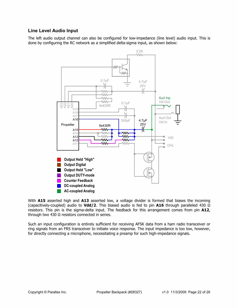
Line Level Audio Input
The left audio output channel can also be configured for low-impedance (line level) audio input. This is done by configuring the RC network as a simplified delta-sigma input, as shown below:
A11A12A13A14A15
A16A17A18A19
A20
A21
A22
A23
Propeller
25V
4.7µF
Aud Inp
Aud Out
Vid In
Vid Out
2.2K
0.1µF
4x430R
9x430R 25V
4.7µF
VID
OVL
330pF
0.1µF
Output Held "High"
Output Held "Low"
Output DUTY-mode
DC-coupled Analog
AC-coupled Analog
Output Digital
Counter Feedback
With A15 asserted high and A13 asserted low, a voltage divider is formed that biases the incoming (capacitively-coupled) audio to Vdd/2. This biased audio is fed to pin A16 through paralleled 430 Ω resistors. This pin is the sigma-delta input. The feedback for this arrangement comes from pin A12, through two 430 Ω resistors connected in series. Such an input configuration is entirely sufficient for receiving AFSK data from a ham radio transceiver or ring signals from an FRS transceiver to initiate voice response. The input impedance is too low, however, for directly connecting a microphone, necessitating a preamp for such high-impedance signals.
Copyright © Parallax Inc. Propeller Backpack (#28327) v1.0 11/3/2009 Page 23 of 26
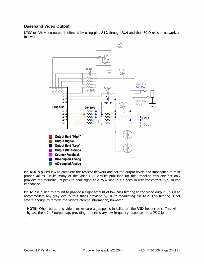
Baseband Video Output
NTSC or PAL video output is effected by using pins A12 through A14 and the 430 Ω resistor network as follows:
A11A12A13A14A15
A16A17A18A19
A20
A21
A22
A23
Propeller
25V
4.7µF
Aud Out
Vid In
2.2K
0.1µF
4x430R
9x430R 25V
4.7µF
VID
OVL
330pF
0.1µF
Output Held "High"
Output Held "Low"
Output DUTY-mode
DC-coupled Analog
AC-coupled Analog
Output Digital
Counter Feedback
A11A12A13A14A15
A16A17A18A19
A20
A21
A22
A23
Propeller
25V
4.7µF
Aud I/O
Vid Out
2.2K
0.1µF
4x430R
9x430R 25V
4.7µF
VID
OVL
330pF
0.1µF
Output Held "High"
Output Held "Low"
Output DUTY-mode
DC-coupled Analog
AC-coupled Analog
Output Digital
Counter Feedback
Pin A16 is pulled low to complete the resistor network and set the output levels and impedance to their proper values. Unlike many of the video DAC circuits published for the Propeller, this one not only provides the requisite 1 V peak-to-peak signal to a 75 Ω load, but it does so with the correct 75 Ω source impedance. Pin A17 is pulled to ground to provide a slight amount of low-pass filtering to the video output. This is to accommodate any gray-level output that’s provided by DUTY modulating pin A12. This filtering is not severe enough to remove the video’s chroma information, however.
NOTE: When outputting video, make sure a jumper is installed on the VID header pair. This will bypass the 4.7 µF output cap, providing the necessary low-frequency response into a 75 Ω load.

Copyright © Parallax Inc. Propeller Backpack (#28327) v1.0 11/3/2009 Page 24 of 26
Video Overlay
The video overlay configuration makes it possible to overlay text on an incoming video signal. It may also be used for superimposing closed-captioning or other data in an incoming signal’s vertical blanking interval. Here’s how it’s done:
A11A12A13A14A15
A16A17A18A19
A20
A21
A22
A23
Propeller
25V
4.7µF
Aud I/O
Aud Out
Vid In
2.2K
0.1µF
4x430R
9x430R 25V
4.7µF
VID
OVL
330pF
0.1µF
Output Held "High"
Output Held "Low"
Output DUTY-mode
DC-coupled Analog
AC-coupled Analog
Output Digital
Counter Feedback
A11A12A13A14A15
A16A17A18A19
A20
A21
A22
A23
Propeller
25V
4.7µF
2.2K
0.1µF
4x430R
9x430R 25V
4.7µF
VID
OVL
330pF
0.1µF
Output Held "High"
Output Held "Low"
Output DUTY-mode
DC-coupled Analog
AC-coupled Analog
Output Digital
Counter Feedback
A11A12A13A14A15
A16A17A18A19
A20
A21
A22
A23
Propeller
25V
4.7µF
Vid Out
2.2K
0.1µF
4x430R
9x430R 25V
4.7µF
VID
OVL
330pF
0.1µF
Output Held "High"
Output Held "Low"
Output DUTY-mode
DC-coupled Analog
AC-coupled Analog
Output Digital
Counter Feedback
DUTY Mode "Transparency"
Sync Input
Duty ModeSync Clamp
Incoming video is coupled through a jumper on the OVL header pair to an analog switch consisting of the two MOSFET transistors. The conductivity of this switch is governed by an output from pin A11. When A11 is high, the switch will conduct fully and pass the incoming video directly to the output. When A11 is low, the switch will not conduct, and the incoming video will be blocked. But there’s more. If you output a DUTY mode signal to A11, the series resistor to the gate and the gate capacitance itself form an RC low-pass filter which allows the “switch” to conduct partially, permitting only partial transmission of the incoming signal to the output. Taken together, along with additional filtering by the 330pF cap, control of this switch permits areas (such as characters or character zones) to be transparent, opaque, or somewhere in between. The brightness of the overlain data is controlled by the same DAC network used for video output. When no overlay is required, these pins may simply be tri-stated so the incoming video can proceed to the output unimpeded. One thing that’s required to do a video overlay is to extract synchronization information from the incoming video signal, so the characters that are overlaid not only appear in their proper positions on the screen but are stable, without any annoying jitter. Sync extraction is normally done with a separate IC,

Copyright © Parallax Inc. Propeller Backpack (#28327) v1.0 11/3/2009 Page 25 of 26
such as an LM1881 from National Semiconductor. But this is not necessary with the Propeller. It’s possible to extract the video’s composite sync with a programmable clamp circuit, as shown in the upper part of the above diagram. The incoming video is capacitively coupled through a series combination of 4.7 µF and 0.1 µF, which is approximately the same as if the larger cap were not present. This signal is input to pin A22. Whenever a low (i.e. a sync level) is detected on this pin, the Propeller program can cause pin A19 to output a DUTY mode signal that clamps this pin just below the Vdd/2 input threshold. (The DUTY mode output is filtered by means of the two series resistors from A19 and the coupling capacitance.) Now this is an obvious chicken-and-egg situation: you have to know when the input is at sync level to know when to provide the DUTY-mode clamp, and you have to provide the clamp at the right time to detect the sync signal. Fortunately, this is a pretty simple operation to bootstrap and consists of randomly sampling the video input and applying the opposite bias until sync is achieved. Once sync has been obtained, maintaining it is a simple matter of timing and application of the clamping signal at the proper times. There is one caveat to observe, however. If the sync tips are clamped to 1.5 V, say, and the input signal exceeds 2.4 V peak-to-peak, the Propeller’s body diodes will clamp the peak values to 3.9 V, which will push the signal too far down for accurate sync detection. But why would this ever happen? Aren’t video signals supposed to be 1V peak-to-peak? Well, no, not always. Without a 75 Ω load, a video signal with the correct 75 Ω source impedance will be 2 V peak-to-peak. It only drops to 1 V when the load is applied. In the overlay circuitry, the input signal may not see a load if the MOSFET switch is not conducting (i.e. when opaque characters or backgrounds are being generated). But 2 V is still well below the 2.4 V maximum. Unfortunately, not every video source is well-behaved in this regard. While it may drive a 75 Ω load okay at a 1 V peak-to-peak level, this signal level may be a lot higher than 2 V without a load, because the source impedance is too high. The “standard” Propeller video DAC is an example. Its output without a load is 3.3 V peak-to-peak, even though its peak output level is 1 V with a 75 Ω load. Some cheap video “board” cameras also exhibit this tendency. In such cases, it will not be possible to provide full opacity to overlaid characters, since the MOSFET switch will have to be at least partially “on” to provide the incoming video with a load. But that’s okay. It will still be possible to generate very readable overlays with a partially transparent background. A fully operational and documented video overlay object is available in an App Note, downloadable from the Propeller Backpack product page.

Copyright © Parallax Inc. Propeller Backpack (#28327) v1.0 11/3/2009 Page 26 of 26
Schematic
A4A5A6A7Vss/BOE/RSTVddA8A9A10A
11
A12
A13
A14
A15
Vss
Vdd
A16
A17
A18
A19
A20A21A22A23VssXIXOVddA24A25A26
A27
SCL
SDA
TxD
RxD
Vss
Vdd
A0
A1
A2
A3
1
11
12
22
23
33
34
44
U2
DB Socket
J3
LM2937IM
P-3.3
VR1
A0
A1
A2
A3
A0
A2
A4
A6
A7
A5
A3
A1
A7A6A5A4
4x4.7K
RP3
4V
15µF
C6
2x100K
RP5
2x150K
4x0.001µF
CP1
A0
A1
Gnd
Vdd
WP
SCL
SDA
A2
1 2 3 45678
24C512
U1
4x4.7K
RP1
+5V
J2
Wh Rd Bk
3-Pin I/O
Port
1µF
C5
1K
R4
R2
10K
2.2K
R1
Reset
SW1
C3
25V
4.7µF
J1
PropPlug Port
Rx Tx Rs Gd
LED1
Aud I/O
J4
Aud O
ut
Vid In
VidOut
16V
C4
10uF
R3
2.2K
RP4
1µF
C1
C2
0.1µF
RP2
4x430R
XT1
10 M
Hz
Q1
4x430R
RP6
4x430R
RP7
R5
430R
25V
C9
4.7µF
Q2
VID
OVL
C7
330pF
C8
0.1µF
Propeller Backpack (Rev. E) Schematic
Propeller chip
(P8X32A-Q
44 LQFP)