ProOSEK Simulator - .: Learn to walk and run a little bitsegment displays, the SevenInit() function...
66
ProOSEK ® Simulator User’s Guide Version 1.0 Edition 1
Transcript of ProOSEK Simulator - .: Learn to walk and run a little bitsegment displays, the SevenInit() function...

ProOSEK®
SimulatorUser’s Guide
Version 1.0Edition 1

Copyright 1996 - 2002 3SOFT GmbH
ALL RIGHTS RESERVED. No part of this publication may be copied in any form, by photocopy, microfilm, retrieval system, or by any other means now known or hereafter invented without the prior written permission of 3SOFT GmbH.
ProOSEK® is a registered trademark of 3SOFT GmbH.
All other trademarks used in this document are the property of their respective owners.
3SOFT GmbHFrauenweiherstr. 1491058 ErlangenGERMANY
support telephone:+49 - 9131 - 7701 - 360
support fax: +49 - 9131 - 7701 - 369
http://www.3SOFT.de
ProOSEK® Simulator, 1.0Edition 110 Feb 03 Part #: OSEK-SIM GUI
Table 1 modification history
Date Version Changes
Jan. 2003 1 Initial
http://www.proosek.de

Contents
1 Introduction ........................................................................... 7
1.1 Why simulation is needed .................... ..............................7
1.2 Requirements........................................ ..............................9
2 First Steps ........................................................................... 11
2.1 Configure the Demo........................... ..............................11
2.2 Start the Compiler .............................. ..............................12
2.2.1 Visual C++ ................................................................... 12
2.2.2 GCC .............................................................................. 13
2.3 Test the Demo Program ..................... ..............................13
3 Graphical Environment ......................................................... 17
3.1 Introduction........................................ ..............................17
3

ProOSEK® UsersGuide
3.2 Handling the GUI............................... ..............................18
3.3 The IO-Components .......................... ..............................20
3.3.1 Speedometer element ................................................... 20
3.3.2 Seven segment display ................................................. 21
3.3.3 LED display ................................................................. 22
3.3.4 DIP switch .................................................................... 23
3.3.5 Button element ............................................................. 24
3.3.6 Slider element .............................................................. 25
3.3.7 LCD display ................................................................. 26
3.3.8 Text display .................................................................. 27
3.3.9 User defined components ............................................. 28
3.4 The Tracer.......................................... ..............................29
3.4.1 Tracer Options ............................................................. 29
3.4.2 The Stackwatch ............................................................ 32
3.4.3 The Eventfinder ........................................................... 33
3.4.4 The Socket element ...................................................... 34
4 Developing with the GUI ....................................................... 35
4.1 Introduction........................................ ..............................35
4.2 Development Workflow .................... ..............................36
4.3 Using the IO-Components ................. ..............................37
4.3.1 Initialisation ................................................................. 37
4.3.2 Sample 1 ...................................................................... 37
4.3.3 Sample 2 ...................................................................... 38
4
Contents
4.4 Programming the Tracer .................... ..............................39
4.4.1 User defined events ...................................................... 39
4.4.2 Controlling the trace .................................................... 39
4.5 Interrupt simulation............................ ..............................41
4.6 Transporting data to the socket element ............................................................42
Simulator API Reference ............................................................. 45
Tracer API Reference .................................................................. 57
Index ............................................................................................. 63
5

ProOSEK® UsersGuide
6

1Introduction
1.1 Why simulation is needed
Developing embedded applications is a time consuming job. With the simulation it is possible to start programming the embedded application while you are waiting for your hardware. This prototype can be created with a full working OSEK system running on Windows NT/2000/XP. The advantage is that the prototype is already tested when moving to the real hardware.
The development of a prototype is supported by the simulator of ProOSEK. There are different components, which help to build a simulation environment.
– Buttons
– Sliders
– LEDs
– LCD-Display
– DIP Switch
7

ProOSEK® Simulator UsersGuide
Another feature of the GUI is the tracing facility. There are different objects and events displayed:
– Task switches
– Api calls ( with parameters )
– Hooks
– Interrupts
– User defined events
– Stack usage
Figure 1-1 shows a screenshot of the graphical environment:.
Figure 1-1 GUI with tracer window
8

1
Introduction
1.2 Requirements
– Windows NT / 2000 / XP
– ProOSEK 4.0 (Win32x86)
– Developing environment Visual C++ 6.0 or higher or GNU C
9

ProOSEK® Simulator UsersGuide
10

2First Steps
2.1 Configure the Demo
In order to test the installation it is recommended to make a test run with the supplied demo. The first step is to run the Configurator and load the demo.oil file. All available options for the configuration can be found in the User’s Guide to ProOSEK. For now it is enough to set the generation path to the demo directory and start generating the OS. For seeing the traceg be sure to switch on GUITRACE, USEPARAMETERACCESS, SERVICETRACE and set the TRACEBUFFER to 10. Now an instrumented kernel is created.
Figure 2-1 Configuration screen with GUITRACE
11

ProOSEK® UsersGuide
2.2 Start the Compiler
2.2.1 Visual C++
After opening the demo.dsw file the Figure 2-2 should look like this:
The Include path to ProOSEK must be added under Tools Options Directories Include Path. (e.g. c:\ProOsek4\include\arch\win32x86)
After compiling a demo.exe is created. When starting the program a DOS box with the running OSEK is presented.
Figure 2-2 Development Enviroment Visual C++
Figure 2-3 Running OSEK simulation
12

2
First Steps
2.2.2 GCC
For users that don’t want to use Visual C++, it is possible to produce the same application with the provided makefile. The command would be
c:\ProOSEK4\bin\make CPU=Win32x86
2.3 Test the Demo Program
Starting the application you will see the environment as shown in Figure 2-4. The first action is normally to move the simulator Icon with drag and drop into the working area.
Next thing is starting the OSEK Simulation by clicking on "Connect". Often many OSEK Simulations are running simultaneous. Therefore a name (here
AvailableItems
Working Area
Icon for theOSEK Sim
Connect Button for OSEK Sim
Figure 2-4 The Gui for the Simulator
13

ProOSEK® UsersGuide
"DEMO share") must be entered to connect the GUI with the right OSEK simulation like shown in Figure 2-5. You will see, that the OSEK icon shows connection points. There you can connect the suitable elements with the OSEK simulator.
In Figure 2-6 there is already a connection between the OSEK simulator and a LED element. The free pin can be used to create a connection between simulator and tracer.
Figure 2-5 Dialog where the Connect Name must be entered
Figure 2-6 OSEK simulator connected to LED
14
2
First Steps
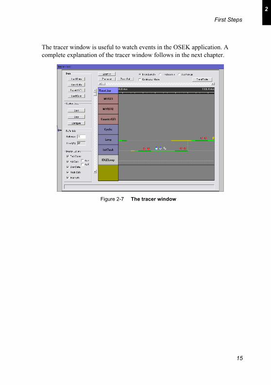
The tracer window is useful to watch events in the OSEK application. A complete explanation of the tracer window follows in the next chapter.
Figure 2-7 The tracer window
15

ProOSEK® UsersGuide
16

3Graphical Environment
3.1 Introduction
This chapter gives an overview to the graphical user interface. This includes the handling of the GUI, a presentation of all available graphical IO-components and the possibilities of the tracer window.
17

ProOSEK® UsersGuide
3.2 Handling the GUI
Every Element on the Left side can be moved with the mouse to the right
working area. By clicking on the elements title (on the working area) the element is selected. To delete the selected element press the DEL (Entf) Key. The connections between two pins is done drawing a line between the two pin. To delete the connection, it must be selected, and DEL-key pressed.
NOTE: Deleting a element deletes all connections to and from this element
Available Items
Working Area
Icon for the OSEK Sim
Connect Button for OSEK Sim
Figure 3-1 The Gui for the simulator
18

3
Graphical Environment
The view can be saved and loaded. The four last recent used files are shown in the menu.
NOTE: If you load a view that does not fit to the connected OSEK simulation you will see that not suitable connections will be deleted.
Figure 3-2 Menu for Load Save
19

ProOSEK® UsersGuide
3.3 The IO-Components
There are several different IO-Components that can be used to build the simulation environment. Each component is shown as picture and the interfaces to the IO-Component are given. The complete reference to the interfaces can be found in Appendix A.
3.3.1 Speedometer element
The speedometer element can be used to simulate an analog instrument. Inertia
of the pointer is implemented. This element is part of those elements that visualize a single value. Therefore it can be replaced dynamically with other elements that represent a single value like the LED display. In Table 3-1 the Interface shows how the speedometer can be used in the user program.
Table 3-1 Interface for the speedometer
int TMInit(int max) Initialisation of a speedometer with a given maximum speed, returns an id for the element
int TMInitEx(int max, char* name)
the same as TMInit but additional a can be set for the component, returns an id for the element
TMSet(int id, int value) sets the actual speed
Figure 3-3 The speedometer
20

3
Graphical Environment
3.3.2 Seven segment display
The seven segment display simulates a passive component, where the 7 segments can be individually switched on and off.
The example driver implementation converts input values from 0 to 15 to the corresponding segments (see Table 3-2 ). For applications that need more segment displays, the SevenInit() function can be called several times. To set a value on the specific seven segment, provide the corresponding id.
Table 3-2 Interface for seven segment display
int SevenInit() creates a new seven-segment, returns the id to the new element
int SevenInitEx(char* name) additional a name can be given to the element
void SevenSetValue(int id , int value)
a value between 0 and 15 sets the appropriate segments of the display
Figure 3-4 The Seven-Segment-Display
21

ProOSEK® UsersGuide
3.3.3 LED display
Every evolution board has a LED display. The first steps when starting developing a embedded program, is to use the LED display. In the simulation the LED display can have n LEDs.
When you create several LEDs it is useful to use the LEDInitEx function and assign each LED line a different name. That name will be display in the GUI as exemplified in Figure 3-5. The mapping of the value to a single LED corresponds to the bit on the n position set to 1 or 0. To switch all 8 LEDs on you have to write LEDSet( id, 255 ).
Table 3-3 Interface for LED display
int LEDInit( int n ) generates a LED display with n LEDs, returns the id of the newly created LED display
int LEDInitEx( int n, char* name )
the name, that is given this function will be shown in the GUI
void LEDSet( int id, int value ) Sets the LEDs to a certain value
Figure 3-5 The LED display
22

3
Graphical Environment
3.3.4 DIP switch
Often evaluation boards not only have LEDs, some of them offer a DIP switch. This can be simulated as seen in Figure 3-6. The DIP control offers n switches. They can be initialized with DIPInit and read out by DIPGet.
The switch on the n-th position represents the n-th bit int the value returned by DIPGet.
Table 3-4 Interface for a DIP Switch
int DIPInit( int n ) Initializes a DIP switch with n switches, returns a id to the switch element
int DIPInitEx( int n, char* name )
the same as above, butthe name given here is shown in the GUI
int DIPGet( int id ) returns the actual value of the DIP switch
Figure 3-6 The DIP switch element
23

ProOSEK® UsersGuide
3.3.5 Button element
The button is realized as normal Windows button. The behaviour in the OSEK application is not the same as in Windows, because, there is no message loop which would handle a button click.
As soon as the button was pressed the ButtonGet function returns one. Repeated Calls to ButtonGet also return 1 for pressed state. To release the state ButtonReset must be called.
Table 3-5 Interface for a Button
int ButtonInit( ) Initializes a button, returns the id of the button element
int ButtonInitEx( char* name ) Alternatively a name can be set, when initializing the button
int ButtonGet( int id ) reads if the button was pressed
void ButtonReset( int id ) resets the button to unpressed
Figure 3-7 The button element
24

3
Graphical Environment
3.3.6 Slider element
The slider simulates a element that generates an analog value. The maximum value must be set with the SliderInInit function.
The user program has the possibility to read the analog value by calling SliderGet( ). Every time the slider is moved, an event is generated. This event can be used to simulate an interrupt on the osek system. The detailed description can be read in Chapter 4.
Table 3-6 Interface for a slider element
int SliderInInit( int max ) Initializes a new slider element with a given maximum value, returns the id of the element
int SliderInInitEx( int max , char* name )
the name is provided for Identification in the GUI
int SliderGet( int id ) read the actual position of the slider
Figure 3-8 The slider as input element
25

ProOSEK® UsersGuide
3.3.7 LCD display
The simulation of a LCD display is very interesting in conjunction with the separately available Graphics library. Without that library the graphic functions for drawing lines, circles, menus and instruments must be implemented by the user.
The mapping from the graphic buffer, which is returned be LCDInit, is mapped to the screen as seen in Figure 3-9.
The transmitting of the buffer can be stopped with LCDStop. After this call LCDRefresh does nothing.
Table 3-7 Interface for the LCD display
void LCDInit(unsigned char* x , unsigned char*y , unsigned char** buffer );
Initializes the LCD display, x and y reference to the width and height of the display and buffer corresponds to the display buffer.
void LCDStart(void); activates the display
void LCDStop(void); disables the display
void LCDRefresh(void); transmits the display data from the buffer to the real display buffer
Figure 3-9 The LCD element showing the graphic library
26

3
Graphical Environment
3.3.8 Text display
The text display named CRT can be used as replacement for console output. A
After initialization with a give size, the text can be set with CRTOuput. Consecutive calls to CRTOutput overwrite each other.
Table 3-8 Interface for text display
int CRTInit( int size ) Initializes a text output control with a given size
int CRTInitEx( int size, char* name )
the same function as above plus the name is given to the control
void CRTOutput( int id, char* text )
outputs the text in the display
For new line put \r \n in your text.
Figure 3-10 The Text display
27

ProOSEK® UsersGuide
3.3.9 User defined components
In the future it will be possible to program own components. This will be done with the help of a predefined COM-Interface. Ask 3SOFT for implementation status.
28

3
Graphical Environment
3.4 The Tracer
3.4.1 Tracer Options
This chapter describes the tracer window with all its options to set or use.
Data
Load Data Loads binary tracebuffer data (future: from debugger)
Save Data Saves tracebuffer data as binary
Export ASCII Exports the trace buffer in a human readable form
Load Conf Load the conf file corresponding to the osek app. This file is always created by the ProOSEK Configurator.
Figure 3-11 The Tracer window
29

ProOSEK® UsersGuide
Capture Data
Buffer Info
This area shows information about the trace buffer in the gui. Buffersize contains the size in MB and buffer used says how much of it is already used.
Zoom options
Start Starts capturing data (default)
Stop Stops capturing data
Configure A dialog box shows all available tracing option. They can be checked on or off.
The control, which data should be captured and when capturing should be stopped can also be set in the OSEK application (see Chapter 4)
ZoomIn In time based mode the ZoomIn can be used to zoom to the selected range. In other modes it zooms by 2.
ZoomOut Zooms in all modes by factor 0.5
Zoom Full In time based mode Zoom Full displays the complete tracebuffer, in eventbased mode, the space between events is reduced to a minimum.
30

3
Graphical Environment
Display options
These options let the user decide which occurrences are interesting and which should be not visible.
Display modes
There are two main display modes - the time based and the event based mode.
Adv Advance Counter often is of no interest and can be disabled with this switch
ApiE Normally only the begin of a Api Call is displayed. If you wish to see the end of a api call then you must switch on this check box
Figure 3-12 Display options
Figure 3-13 Time based view versus event based view
31

ProOSEK® UsersGuide
The time based mode displays all events according to their occurrence. Some events like Interrupts may be very narrow (see Figure 3-13 left). If you are not interested in the proportions of the times, perhaps the event based mode is a good choice. There every occurrence of an event has the same space available (Figure 3-13 right).
3.4.2 The Stackwatch
The Stackwatch displays the stack usage for each task. The maximum stack is read from the conf file provided from the configurator. The actual usage is taken from calculating the stack usage at every task switch.
These values can give you a rough idea of how much stack the application will use. It is not an exact value, because between task switches the application may use much more stack. If you want to check how much stack the tasks consumed see 4. Developing with the GUI. The checked value shows this values.
Figure 3-14 The Stackwatch
32

3
Graphical Environment
3.4.3 The Eventfinder
The Eventfinder is a small helper that lets you find events especially when you have zoomed in often. If you want to track all api calls to Release Resource you click on one occurrence and then click on the right or left arrow. This will bring you to the next event match the criteria given in the eventfinder window. The check box beside the edit boxes denote which criteria must match when searching for the next event.
Figure 3-15 The Eventfinder Window
33

ProOSEK® UsersGuide
3.4.4 The Socket element
The graphical enviroment offers a socket element. This can be used to connect to the GUI with TCP on port 8000. So real hardware tracing can be performed, if you have an instrumented kernel for your target and a transport layer. A sample source code for transmitting via sockets is described in the next chapter.
Figure 3-16 The socket element
34

4Developing with the GUI
4.1 Introduction
The ProOSEK® systems consists of the graphical Configurator and a given file structure which together form the ProOSEK® solution. In order to work properly with the environment it is important to understand how the different tools work together.
Furthermore ProOSEK® comes with a predefined directory structure the user should be familiar with. On the other hand experienced users may change the way the process works by default settings to meet their requirements
35

ProOSEK® UsersGuide
4.2 Development Workflow
The following figure gives an overview of the ProOSEK® developing process.
User filesOIL File
Configurator
Kernel Sources
Conf - File
Link
OSEK.exe
Gui Drivers
User Drivers
GUI.exe
36

Developing with the GUI
4
4.3 Using the IO-Components
4.3.1 Initialisation
When using the IO-Components, the first action must be a call to InitGuiInternal(). This function creates internal structures to handle the different components. If you use the tracing option from the ProOSEK Configurator, InitGuiInternal() will be called from the operating system. You also have to assign your application a unique name. This name must be entered in the GUI in order to connect with your program.
4.3.2 Sample 1
The first example shows a simple application that reads an input value from a DIP switch and puts the result to a LED line.
char* connectString ="DEMO share";
Figure 4-1 Assign a name to the osek app
{
int value;
int dip_id;
int led_id;
dip id = DIPInit( 8 ); // creates a DIP with 8 switches
led_id = LEDInit( 8 ); // creates a LED with 8 lights
value = DIPGet( dip_id ); // read the value from the DIP
LEDSet( led_id , value ); // write it to the LED
}
Figure 4-2 Sample Code that shows the use of a LED and a DIP
37

ProOSEK® UsersGuide
4.3.3 Sample 2
The second example shows the use of a button control and of the seven segment display.
TASK(Loop)
{
int counter = 0;
int button_id;
int seven_id;
button_id = ButtonInit(); // create the button
seven_id = SevenInit(); //create the seven segment
while( 1 )
{
if ( ButtonGet( button_id ) ) // check button state
{
ButtonReset( button_id ); // set buttonstate to 0
counter++;
if( counter >15 )
counter = 0;
SevenSetValue( seven_id, counter ); // display value
}
}
Figure 4-3 Sample code to demonstrate the use of theButton and the seven segment
38

Developing with the GUI
4
4.4 Programming the Tracer
There are two possibilities to take influence on the tracer. The first is to create user defined events that are displayed in the trace window. The other thing is to control the global tracing behaviour by selecting individual tracing modes.
4.4.1 User defined events
Sometimes the user wished to log more than the standard tracing implicitly does. For that case there are two functions offered, which make it possible to create user defined events. Normally the Tracer_User_Data() function will be used. Only for some special cases the Tracer_User_Cr() may be relevant.
4.4.2 Controlling the trace
In Chapter 3 the tracing window has some switches to control the tracing. There is another possibility to start, stop and set the tracing mode. For Example to stop tracing one would call Tracer_SetActive( NOT_ACTIVE ). For tracing Task changes and osek apis the call is Tracer_SetActive( TASKSTATE | APICALL). The Tracer_Init() and Tracer_BufferClose() function are implicitly called by the osek system.
Table 1 Tracer user events
void Tracer_User_Data( OSEK_U8 ud_id , char* data, OSEK_U16 size )
Creates a user defined event with a given id. If size of data is greater USER_DATA_SIZE, the user data is splitted in up to 255 parts.
void Tracer_User_Cr( OSEK_U8 ud_id , char* data, OSEK_U16 size )
This function should only be called in a locked environment. (During Interrupts are locked). The size is limited to USER_DATA_SIZE. This function is useful when tracing in the kernel.
39

ProOSEK® UsersGuide
Table 2 Tracer control
void Tracer_Init( ) This function is automatically called from the OS, when GuiTrace is enabled in the Configurator
int Tracer_SetActive( int mode )
Set the traces logging mode (see Table 3 for available modes). Returns old mode.
void Tracer_BufferClose() This function sends the tracebuffer to the gui and ends tracing. It is called automatically during OSShutdown
The enable more than one mode you have to or ( | ) the modes you wish to set.
Table 3 Mode for the Tracer
NOT_ACTIVE Switch all tracing off
TASKSTATE Log task state changes
TIME Log Time stamps
APICALL Log Api Calls
USERDATA Log user defined events
HOOKCALL Log hook calls
INTCALL Log interrupt calls
STACKTRACE Log stack pointers
40
Developing with the GUI
4
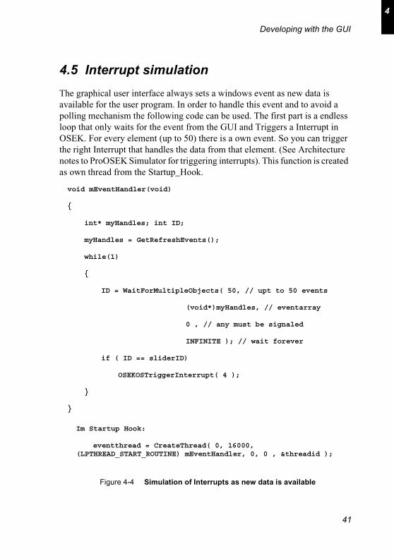
4.5 Interrupt simulation
The graphical user interface always sets a windows event as new data is available for the user program. In order to handle this event and to avoid a polling mechanism the following code can be used. The first part is a endless loop that only waits for the event from the GUI and Triggers a Interrupt in OSEK. For every element (up to 50) there is a own event. So you can trigger the right Interrupt that handles the data from that element. (See Architecture notes to ProOSEK Simulator for triggering interrupts). This function is created as own thread from the Startup_Hook.
void mEventHandler(void)
{
int* myHandles; int ID;
myHandles = GetRefreshEvents();
while(1)
{
ID = WaitForMultipleObjects( 50, // upt to 50 events
(void*)myHandles, // eventarray
0 , // any must be signaled
INFINITE ); // wait forever
if ( ID == sliderID)
OSEKOSTriggerInterrupt( 4 );
}
}
Im Startup Hook:
eventthread = CreateThread( 0, 16000, (LPTHREAD_START_ROUTINE) mEventHandler, 0, 0 , &threadid );
Figure 4-4 Simulation of Interrupts as new data is available
41

ProOSEK® UsersGuide
4.6 Transporting data to the socket element
#define SERVER_IP_ADDRESS 2130706433 // 127.0.0.1 to bits upto 255 each field.
#define SERVER_TCP_PORT 8000 // Server-Port in Gui.exe
int server_socket;
void SocketInit( )
{
struct sockaddr_in server_address;
// Initialise server address structure.
WSADATA WSAData;
int init = WSAStartup( MAKEWORD( 2, 2 ) , &WSAData );
memset((char *) &(server_address),0, sizeof(server_address));
server_address.sin_family = AF_INET;
server_address.sin_port = htons(SERVER_TCP_PORT);
server_address.sin_addr.s_addr = htonl(SERVER_IP_ADDRESS);
// Create socket.
server_socket = socket(PF_INET, SOCK_STREAM, IPPROTO_TCP );
// Connect to server socket.
if (connect
(
server_socket,
(struct sockaddr *) &(server_address),
sizeof(server_address)
) < 0)
{
perror("connect");
exit(EXIT_FAILURE);
}
}
42

Developing with the GUI
4
void SocketOutTest( )
{
char buffer[SIZE_OF_BUFFER];
int size;
ATOMIC_START;
memset( buffer, 0, SIZE_OF_BUFFER );
size = getNextEntry( &buffer[8] ); // read next entry from ring buffer
if ( size != -1 )
{
int dummy,i;
*(int*)(&buffer[0]) = 0;
*(int*)(&buffer[4]) = 0;
// experimental checksum calculation
dummy = 462;
for( i = 8; i < 8 + size; i++ )
{
dummy += buffer[ i ];
}
buffer[ 8 + size ] = (char) dummy;
send( server_socket, buffer, 8 + size + 1, 0);
}
ATOMIC_END;
}
43

ProOSEK® UsersGuide
4.7 Tracing real used Stacks
for( i = 0; i < TMAX ; i++ )
{
Tracer_Stack( i , getUsedTaskStack(i), 0 , 1 );
}
Tracer_Stack( TMAX , getUsedIsrStack(), 0 , 1 );
Figure 4-5 Tracing maximum stack usage
44

ASimulator API Reference
ButtonGet( )
NAME ButtonGet( ) - gets the state of a button control
SYNTAX int ButtonGet
(
int buttonID/* reference to a button control
created by ButtonInit*/
)
DESCRIPTION This routine gets the state of a button. If the specified button was currently pressed the function returns 1. If it was not pressed the return value is 0. If value was 1 it can be reseted to 0 with ButtonReset()
AVAILABILITY This service may be called from the task and interrupt level. It must not be called before InitGuiInternal() and ButtonInit().
RETURNS The state of the button is returned.
ERRNO
CONFORMANCE BCC1, BCC2, ECC1, ECC2
45

ProOSEK® UsersGuide
ButtonInit( ) - ButtonInitEx( )
NAME ButtonInit( ) - initializes a button
SYNTAX int ButtonInit
(
)
int ButtonInitEx
{
char* buttonname /* name of button */
}
DESCRIPTION This routine initializes a new button. Each time the function is called a new button will be created and the according id is returned. ButtonInitEx can be used to give the element a name. This name is displayed in the GUI.
AVAILABILITY These functions can be called after InitGuiInternal().
RETURNS The id of the new button
CONFORMANCE BCC1, BCC2, ECC1, ECC2
ButtonReset( )
NAME ButtonReset( ) - resets the state of a button
SYNTAX int ButtonReset
(
int buttonID /* reference to the button */
)
DESCRIPTION This routine resets the state of a given button.
46

Simulator API Reference
A
AVAILABILITY This function can be called after InitGuiInternal() and ButtonInit()
RETURNS
CONFORMANCE BCC1, BCC2, ECC1, ECC2
CRTInit( ) - CRTInitEx( )
NAME CRTInit( ) - initializes a text output element
SYNTAX int CRTInit
(
int size /* size of text buffer */
)
int CRTInitEx
(
int size, /* size of text buffer */
char* name /* name of crt element */
)
DESCRIPTION This routine initializes a new text output element. After creating it returns a id of the new element. The CRTInitEx function additionally accepts a name that will be displayed in the GUI.
AVAILABILITY This service may be called from the task level and from the interrupt level after InitGuiInternal() was called.
RETURNS The id of the new text output element.
ERRNO
CONFORMANCE BCC1, BCC2, ECC1, ECC2
47

ProOSEK® UsersGuide
CRTOutput( )
NAME CRTOutput( ) -
SYNTAX void CRTOutput
(
int crtID, /* reference to the text output
element*/
char* outputtext
)
DESCRIPTION This routine sends the outputtext to the crt element with the given crtID. The text up to the specified size in the CRTInit( ) function is transmitted.
AVAILABILITY This routine may be called from the task level and interrupt level. InitGuiInternal( ) and CRTInit( ) or CRTInitEx( ) have to be called before this function.
RETURNS No return
ERRNO
CONFORMANCE BCC1, BCC2, ECC1, ECC2
DIPGet( )
NAME DIPGet( ) - reads the value of the DIP element
SYNTAX int DIPGet
(
int dipID /* reference to the DIP element*/
)
DESCRIPTION This routine reads the value of the dip switches. If the value is 2^n-1, all switches are set. N is the number of switches that were created by DIPInit().
48

Simulator API Reference
A
AVAILABILITY This function can be called after InitGuiInternal() and DIPInit().
RETURNS No Return
CONFORMANCE BCC1, BCC2, ECC1, ECC2
DIPInit( ) - DIPInitEx( )
NAME DIPInit( ) - initializes a new DIP switch
SYNTAX int DIPInit
(
int n /* number of switches */
)
DESCRIPTION This routine initializes a new DIP element with n switches.
RETURNS The ID of the new DIP element.
AVAILABILITY This function can be called after InitGuiInternal().
CONFORMANCE BCC1, BCC2, ECC1, ECC2
49

ProOSEK® UsersGuide
LEDInit( ) - LEDInitEx( )
NAME LEDInit( ) - initializes a LED element
SYNTAX int LEDInit
(
int n /* number of LEDs */
)
int LEDInitEx
(
int n, /* number of LEDs */
char* name /* element name in GUI */
)
DESCRIPTION This routine initializes a LED element that behaves similar to those on evaluation boards. N is the number of lights the LED element has.
AVAILABILITY This function must not be called before InitGuiInternal().
CONFORMANCE BCC1, BCC2, ECC1, ECC2
LEDSet( )
NAME LEDSet( ) - external declaration of a resource
SYNTAX void LEDSet
(
int ledid, /* reference to LED */
int value /* value that will be set */
)
DESCRIPTION This routine writes the value to the led element. A value of 2^n-1 where n is the number of lights sets alls lights on.
AVAILABILITY This function must not be called before InitGuiInternal() and LEDInit().
50

Simulator API Reference
A
CONFORMANCE BCC1, BCC2, ECC1, ECC2
LCDInit( )
NAME LCDInit( ) - initializes a LCD display
SYNTAX void LCDInit
(
unsigned char* x, /* reference to width*/
unsigned char* y, /* reference to height */
void** refbuffer/* reference to pointer of
buffer */
)
DESCRIPTION This routine initializes a LCD display. After calling the function x and y contain the height and width of the lcd display. RefBuffer is set to the virtual buffer that can be used for drawing.
AVAILABILITY After InitGuiInternal( ) this function can be used.
CONFORMANCE BCC1, BCC2, ECC1, ECC2
LCDRefresh( )
NAME LCDRefresh( ) - refresh the lcd display
SYNTAX void LCDRefresh (void)
DESCRIPTION This routine sends the data from the virtual buffer to the lcd display. This refresh can be activated with LCDStart( ) and disabled with LCDStop( ).
AVAILABILITY This service may be called after LCDInit( ) was called.
RETURNS N/A
51

ProOSEK® UsersGuide
CONFORMANCE BCC1, BCC2, ECC1, ECC2
LCDStart( )
NAME LCDStart( ) - enables transfer to lcd display
SYNTAX void LCDStart (void)
DESCRIPTION This routine enables the transfer from virtual to real lcd memory that is triggered by LCDRefresh().
AVAILABILITY This service may be called after LCDInit() was called.
CONFORMANCE BCC1, BCC2, ECC1, ECC2
LCDStop( )
NAME LCDStop( ) - disables transfer to lcd display
SYNTAX void LCDStop( void )
DESCRIPTION Disables the transfer of memory to the lcd display. Calls to LCDRefresh( ) will be ignored as long as LCDStart( ) is called again.
AVAILABILITY This service may be called after LCDInit( ) was called.
CONFORMANCE BCC1, BCC2, ECC1, ECC2
52

Simulator API Reference
A
SevenInit( ) - SevenInitEx( )
NAME SevenInit( ) - SevenInitEx( ) initializes a seven segment display
SYNTAX int SevenInit (void)
int SevenInitEx
(
char* name /* name of element */
)
DESCRIPTION This function initializes a new seven segment display. It returns the ID as a reference to that element.
RETURNS The id to the new element.
AVAILABILITY Available after InitGuiInternal() was called.
CONFORMANCE BCC1, BCC2, ECC1, ECC2
SevenSetValue( )
NAME SevenSetValue( ) - transforms the value to the segments off the seven segment element.
SYNTAX StatusType SevenSetValue
(
int sevenID, /* reference to the seven s.
element */
int value /* value that shall be displayed */
)
53

ProOSEK® UsersGuide
DESCRIPTION This routine sets the value from 0 -15 to corresponding segments on the seven segment element. The symbols displayed are 0 - 9 and A - F.
AVAILABILITY This function is available after calling SevenInit().
CONFORMANCE BCC1, BCC2, ECC1, ECC2
SliderInInit( ) - SliderInInitEx( )
NAME SliderInInit( ) - SliderInInitEx( )
SYNTAX int SliderInInit()
(
int max /* maximum value */
)
int SliderInInitEx()
(
int max, /* maximum value */
char* name
)
DESCRIPTION This function initializes a slider element. The maximum value the slider can generate is given with max. In SliderInInitEx() a name can be given to the control. This name is displayed in the GUI.
AVAILABILITY This service may be called after InitGuiInternal() was called.
RETURNS The ID as a reference to the new slider element.
CONFORMANCE BCC1, BCC2, ECC1, ECC2
54

Simulator API Reference
A
SliderGet( )
NAME SliderGet( ) - returns the actual slider position
SYNTAX int SliderGet
(
int sliderID /* reference to the slider */
)
DESCRIPTION This routine gets the current position of the slider element. The sliderID was retrieved be the SliderInInit() function.
AVAILABILITY This function is available after SliderInInit() was called.
RETURNS The actual position up the max value defined during Init.
CONFORMANCE BCC1, BCC2, ECC1, ECC2
TMInit( ) - TMInitEx( )
NAME TMInit( ) - TMInitEx( ) create a tacho element
SYNTAX int TMInit
(
int max /* maximum speed */
)
int TMInitEx
(
int max, /* maximum speed */
char* name /* name to display in GUI */
)
DESCRIPTION This routine initializes a new tacho element. With a given speed value it returns a reference to the new element.
AVAILABILITY This service may be called after InitGuiInternal().
55

ProOSEK® UsersGuide
RETURNS The reference to the new element.
CONFORMANCE BCC1, BCC2, ECC1, ECC2
TMSet( )
NAME TMSet( ) - get the task ID of a running task
SYNTAX void TMSet
(
int id, /* ref to tacho element */
int speedValue /* speed */
)
DESCRIPTION This routine sends the actual speed value to the tacho element.
AVAILABILITY It is available after TMInit was called.
CONFORMANCE BCC1, BCC2, ECC1, ECC2
56

BTracer API Reference
Tracer
NAME Tracer - the OSEK tracing API
DESCRIPTION This module provides a general description of the OSEK tracing API.
NAMING CONVENTIONS
All tracing functions start with Tracer_
ERROR CODES The following are OSEK COM defined error codes:
tracing modes Description of tracing modes
NOT_ACTIVE Switch all tracing offTASKSTATE Log task state changesAPICALL Log Api CallsUSERDATA Log user defined eventsHOOKCALL Log hook callsINTCALL Log interrupt callsSTACKTRACE Log stack pointersNEWTRACESTART reserved - must not be set
57

ProOSEK® UsersGuide
TracerInit( )
NAME TracerInit( ) - start the tracing module
SYNTAX void TracerInit (void)
DESCRIPTION The TracerInit( ) service starts the OSEK tracing module. This routine performs the initialization of OSEK tracing implementation-specific internal states and variables. It also initializes the communication to the GUI.
Tracer_SetActive( )
NAME Tracer_SetActive( ) - sets new tracing mode
SYNTAX int MessageInit
(
int mode /* new mode to set */
)
DESCRIPTION This routine sets the tracing mode supplied with mode. The old mode is returned. Available mode can be found at the beginning of the reference. The mode can be connected with logical or.
RETURNS It returns the old tracing mode.
Tracer_BufferClose( )
NAME Tracer_BufferClose( ) - ends tracing
SYNTAX void Tracer_BufferClose( void )
58

B
Tracer API Reference
DESCRIPTION This routine is automatically called when OSShutdown() is called. It flushed the Tracebuffer and notifies the GUI that the osek program has shutdown.
Tracer_TaskChange( )
NAME Tracer_TaskChange( ) - create a task change event in the tracebuffer
SYNTAX void Tracer_TaskChange
(
OSEK_U8 taskid, /* ref. to task */
OSEK_U8 newState /* new State */
)
DESCRIPTION This routine creates a task change event in the Tracebuffer. The newState can be SUSPENDED, READY, RUNNING or WAITING. In ProOSEK the function is automatically called.
Tracer_Api_Call( )
NAME Tracer_Api_Call( ) - traces api calls with param.
SYNTAX void Tracer_Api_Call
(
OSEK_U8 taskid, /* ref to active task */
OSEK_U8 apiid, /* ref to api see os.h */
OSEKOSParameterType* pT /* param struct */
)
59

ProOSEK® UsersGuide
DESCRIPTION The service creates an entry (api call) in the Tracebuffer. The function is called as the user calls an api by the osek system.
Tracer_User_Data( )
NAME Tracer_User_Data( ) - traces user defined data
SYNTAX StatusType Tracer_User_Data (
OSEK_U8 id /* user defined id */
char* data, /* pointer to data */
OSEK_U16 size /* size of data */
)
DESCRIPTION This service creates a user defined event in the tracebuffer. The ids can be chosen by the user. In the GUI the id can be used for searching for events of the same type.
Tracer_User_Cr( )
NAME Tracer_User_Cr( ) - traces user defined messages without disabling interrupts
SYNTAX StatusType Tracer_User_Cr (
OSEK_U8 ud_id ,
char* data,
OSEK_U16 size /* size of data */
)
DESCRIPTION This routine the same as Tracer_User_Data, but only accepts size up to USER_DATA_SIZE. The must not be called if
60

B
Tracer API Reference
interrupts are enabled. The function does not flush the Tracebuffer, if it is already full. There are only some special cases when this function is helpful. Normally Tracer_User_Data( ) should be used.
Tracer_Hook( )
NAME Tracer_Hook( ) - traces a hook call
SYNTAX StatusType Tracer_Hook
(
OSEK_U8 taskid,
OSEK_U8 hook_id,
OSEK_U8 enterleave
)
DESCRIPTION The service is automatically called if hooks are activated in the ProOSEK Configurator. The hook_id can be found in tracer.h.
Tracer_Interrupt( )
NAME Tracer_Interrupt( ) - traces a interrupt call
SYNTAX void Tracer_Interrupt (
OSEK_U8 interruptid,
OSEK_U8 enterleave
)
DESCRIPTION This routine must be called when entering a interrupt service routine and when leaving. Enterleave must be set to ENTER accordingly LEAVE. The interrupt_id can be found in the os.conf file that is created by the Configurator.
61

ProOSEK® UsersGuide
Tracer_Stack( )
NAME Tracer_Stack( ) - traces the stack usage
SYNTAX void Tracer_Stack (
OSEK_U8 taskid,
int usage,
int limit,
int checked
)
DESCRIPTION This routine traces the stack pointer at every task change. It is called automatically be the osek system.
62

Index
Index
B
Button element 24ButtonGet 24ButtonInit 24ButtonInitEx 24ButtonReset 24
C
Connect 13Connection 14Connections 18connectString 37CRTInit 27CRTInitEx 27CRTOutput 27
D
Demo Program 13DIP switch 23DIPGet 23DIPInit 23DIPInitEx 23Display modes 31Display options 31
63

ProOSEK® UsersGuide
E
embedded applications 7Eventfinder 33Export ASCII 29
F
First Steps 11
G
Generation Path 11GUITRACE 11
I
Include Path 12InitGuiInternal 37installation 11instrumented kernel 11Interrupt simulation 41
L
LCD display 26LCDInit 26LCDRefresh 26LCDStart 26LCDStop 26LED display 22LEDInit 22
64

Index
LEDInitEx 22LEDSet 22Load Conf 29
M
makefile 13
O
OSEK 12
P
ProOSEK 7, 11Prototype 7
R
Requirements 9
S
Sample 1 37Sample 2 38SERVICETRACE 11Seven segment display 21SevenInit 21SevenInitEx 21SevenSetValue 21Slider element 25SliderGet 25
65

ProOSEK® UsersGuide
SliderInInit 25SliderInInitEx 25Speedometer 20speedometer 20Stackwatch 32
T
Text display 27TMInit 20TMInitEx 20TMSet 20TRACEBUFFER 11Tracer 14, 29Tracer Window 15Tracer_BufferClose 40Tracer_Init 40Tracer_SetActive 40Tracer_User_Cr 39Tracer_User_Data 39
U
USEPARAMETERACCESS 11User defined events 39
V
Visual C++ 12
66