Proof of Principle for an 8 l-mm Nonlethal Mortar · PDF fileProof of Principle for an 8 l-mm...
23
Proof of Principle for an 8l-mm Nonlethal Mortar Cartridge James M. Gamer David H. Lyon 20020702 083 Approved for public release: distribution is unlimited.
Transcript of Proof of Principle for an 8 l-mm Nonlethal Mortar · PDF fileProof of Principle for an 8 l-mm...

Proof of Principle for an 8 l-mm Nonlethal Mortar Cartridge
James M. Gamer David H. Lyon
20020702 083 Approved for public release: distribution is unlimited.

The findings in this report are not to be construed as an official Department of the Army position unless so designated by other authorized documents.
Citation of manufacturer’s or trade names does not constitute an official endorsement or approval of the use thereof.
Destroy this report when it is no longer needed. Do not return it to the originator.

Army Research Laboratory Aberdeen Proving Ground, MD 2 1005-5066
ARL-MR-543 May 2002
.
.
Proof of Principle for an 8 1 -mm Nonlethal Mortar Cartridge
James M. Garner David H. Lyon Weapons & Materials Research Directorate
Approved for public release; distribution is unlimited.

Abstract
U.S. military forces increasingly find themselves in situations compatible with the use of nonlethal weapons. Operations other than war (OOTW) (including peacemaking, peacekeeping, and humanitarian missions) in locations such as Somalia, Haiti, Bosnia, and Kosovo repeatedly demonstrate the need for nonlethal weapons that are effective in the roles of crowd control and nondestructive area denial. This report describes the development of a nonlethal 81-mm cartridge that is ultimately viewed as a potential tool in OOTW. Payload configurations and specifications are deliberately absent since the round may have a variety of users with various desired payloads. The creation of this round initially augmented the technology developed for previous standard 81-nun mortar projectiles. The dimensions and weights of the prototype round are such that the round requires no special logistics or handling and is similar in appearance and operation to current rounds, making its employment nearly transparent to the user. Proof-of-principle testing is a logical progression from the initial concept demonstration performed in collaboration between the U.S. Army Research Laboratory and United Defense Limited Partnership. The report discusses nonlethal, 81-mm mortar projectile advancements in expulsion charge parameters and parachute deployment schemes for the prototype. An explanation is also given for the partially successful parachute deployment that occurred in the early phase. Replacement of various round components and their associated benefits are also discussed. The prototype round is intended to employ current technology and hardware with currently available components to create a reliable, cost-effective design. The round has demonstrated functionality and is further proposed as the test vehicle for imminent payload dispersion studies. Other evolutionary designs are also offered as vehicles for improving reliability and augmenting the proven technology described herein.
ii

ACKNOWLEDGMENTS
Several people contributed and continue to contribute to the development of the nonlethal 81-mm mortar cartridge. The status of the cartridge is the culmination of several areas of effort. Richard Johnson of UDLP (United Defense Limited Partnership), Minneapolis, Minnesota, was invaluable in providing the initial prototype round and functioning scheme. The round underwent modifications to improve stability through the efforts of Bernard Guidos of the U.S. Army Research Laboratory (ARL) and Ameer M&hail of the U.S. Army Materiel Systems Analysis Activity. Joseph Domanico of the Pyrotehnics team of the U.S. Army Soldier Biological and Chemical Command (SBCCOM) did a terrific job of rapidly procuring and assembling projectile parts to support testing. Donald McClellan of Dynamic Science, Incorporated, contributed substantially to parachute deployment schemes and test support. The efforts of Brendan Patton of ARL and Mark Ward of SBCCOM in obtaining hardware and conducting timely testing were also essential to the success of the firings. Finally, the sponsorship and guidance of the U.S. Armament Research, Development, and Engineering Center’s Robert Worth, Matt Evangelisti, and Jim Terhune are also recognized.
. . . Ill

INTENTIONALLY LEFT BLANK
iv

Contents
1. Introduction .............................................
2. W-mm Nonlethal Round Specifications ........................
3. Proof of Principle. ........................................
4. Future Designs ...........................................
5. Conclusions.. ...........................................
References ...................................................
Distribution List ...............................................
Report Documentation Page ......................................
Figures
1. The Sl-mm M301A3 Mortar Round With Propellant Increments. .......... 2. The 81-mm Nonlethal Mortar Round ............................. 3. A One-Parachute Deployment. ................................. 4. Tail Cone Assembly With Spring Ejection .......................... 5. Probable Error Seen in Early Firings .............................. 6. Schematic for Single-Parachute Design ............................
Tables 1. Listing of Current Nonlethal Weapons and Respective Ranges ............ 2. Listing of M301A3 and Nonlethal Mortar Round Physical Properties ....... 3. Expulsion Charge Weights and Predicted Pressures for Four 0.25-in. Shear Pins
1
2
4
8
9
11
13
15
1 3 5
V

INTENTI~NAILY LEFT BLANK
vi
PROOF OF PRINCIPLE FOR AN 81-MM NONLETHAL MORTAR CARTRIDGE
1. Introduction
1
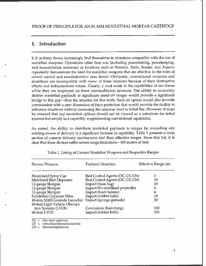
U.S. military forces increasingly find themselves in situations compatible with the use of nonlethal weapons. Operations other than war (including peacemaking, peacekeeping, and humanitarian missions) in locations such as Somalia, Haiti, Bosnia, and Kosovo repeatedly demonstrate the need for nonlethal weapons that are effective in the roles of crowd control and nondestructive area denial. Obviously, conventional weapons and munitions are incompatible with many of these missions because of their destructive effects and indiscriminate nature. Clearly, a void exists in the capabilities of our forces while they are employed on these non-traditional missions. The ability to accurately deliver nonlethal payloads at significant stand-off ranges would provide a significant bridge to this gap-thus the impetus for this work. Such an option would also provide commanders with a new dimension of force protection that would provide the facility to influence situations without increasing the response level to lethal fire. However, it must be stressed that any nonlethal options should not be viewed as a substitute for lethal systems but simply as a capability supplementing conventional capabilities.
As stated, the ability to distribute nonlethal payloads to ranges far exceeding any existing means of delivery is a significant increase in capability. Table 1 presents a cross section of current delivery mechanisms and their effective ranges. From this list, it is clear that these devices suffer severe range limitation-100 meters at best.
Table 1. Listing of Current Nonlethal Weapons and Respective Ranges
Device/Weapon Payload/Munition Effective Range (m)
Hand-held Spray Can Mid-Sized Riot Dispenser 12-gauge Shotgun 12-gauge Shotgun 12-gauge Shotgun Nonlethal Claymore Mine 40-mm M203 Grenade Launcher 66-mm Light Vehicle Obscura-
tion Systems (LVOS) 66-mm LVOS
Riot Control Agents (OC, CS, CN) Riot Control Agents (OC, CS, CN) Impact (bean bag) Impact (fin-stabilized projectile) Impact (foam batons) Impact (rubber balls) Impact (sponge grenade)
Concussion (flash bang) Impact (rubber balls)
3 10 10 4 4 10 30
100 100
OC = oleo resin capsicum CS = orthochlorobenzalmalonitrile CN = chloroacetaphenone

Because of their limited range, most devices require the user to be near the target in order to effectively deliver the payload. This significantly increases the level of user exposure and therefore the risk to retaliatory actions. Furthermore, these items are employed in a line-of-sight mode that again intensifies the level of exposure-related risk to the user. Considering these characteristics, an indirect fire weapon such as a mortar, seems a logical choice to overcome many of the noted detractions. While specific users of nonlethal mortars and their associated doctrine have yet to be established, the mortars’ increase in range is accepted as a significant benefit. Conventional mortar cartridges, designed to deliver payloads, are manufactured from metallic components of significant mass and lethality. After payload expulsion, these components are allowed to fall freely to the ground, producing a significant risk of injury. Attaining the increased ranges and dispersing the payload while reducing the velocities/energies of the discarding parts to nonlethal status is primary to the proposed 81-mm round.
2. M-mm Nonlethal Round Specifications
Figure 1 is a photograph of the M301A3 illuminating projectile and Figure 2 is a photograph of the proposed nonlethal projectile.
Figure 2. The 81-mm Nonlethal Mortar Round (shown with fuze wires).
2

Table 2 presents a comparison of physical properties. The 81-mm nonlethal mortar dimensions were chosen to offer the maximum payload volume, yet comply with the logistical constraints associated with standard mortar rounds. The M301A3’s properties are given for reference 111.
Table 2. Listing of M301A3 and 81-mm Nonlethal Mortar Round Physical Properties
M301A3 Sl-mm Nonlethal
Length (inches) Weight (pounds) Center of Gravity (inches
from nose) Fin Length (inches) Payload Volume (in”) Number of parachutes
24.74 25 10.1 5.83 8.75 10.25
4.38 6.00 18.9 (ilhuninant volume) 33.9 (available volume) 1 2
3
Mitigation of kinetic energy (KE) after payload dispersal was the primary motivator that drove the design process. Various schemes to accomplish this task were conceived and reviewed for feasibility. These included front or rear deployment of a single parachute/drag device and a fracturing or self-destructing body and a dual parachute/drag device design. The choices were narrowed, based on functional and manufacturing complexity, projected reliability, and payload dispersal. In addition, the sequence of the two-parachute deployment and its effect on the subsequent submunition dispersal were considered in detail.
A drag device and/or two-parachute configuration, in which one parachute is tethered to the nose cone body and is positioned aft of the payload, was chosen as most promising. The second parachute occupies the tail cone fin assembly. The sequence of events was envisioned to occur in the following manner: when the expulsion charge (positioned in the nose cone of the cartridge) is activated, it separates the cartridge at the body-tail cone assembly interface. The body parachute deploys, slowing the body and nose cone by 60% to 70%. Following the deployment of the parachute, the submunitions disperse. The parachute for the fin assembly deploys separately and reduces the KE of this remnant to a nonlethal velocity. As a benchmark, most of the nonlethal community uses 58 ft-lb as the threshold energy value of nonlethality. There is no absolute standard because prediction of mortality largely depends upon the health of the individual involved.

3. Proof of Principle
The stated goal of the proof-of-principle firings was to verify the operation and thereby validate the concept and configuration of the round. Previous experiments in May 2000 yielded moderate success. Fired rounds demonstrated that the aerodynamics and associated range predictions characterized the round’s performance well, but only one parachute (attached to the nose section) deployed. The parachute stored in the tail cone section often remained in that section until impact. This partial success paved the way for a second round of experimentation, the thrust of which was to identify and ensure the deployment of two parachutes. A firing result from an April 2001 firing is shown in Figure3, although in this case, the front parachute did not deilov.
Figure 3. A One-Parachute Deployment.
The drag device (parachute) deployment sequence that was originally considered assumed that parachute deployment could occur concurrently with payload expulsion at approximately 100 m above the target. It was reconsidered and upon further reflection, was determined to be at odds with the accuracy requirement for the round. Although this sequence would achieve the nonlethal velocities for the remnants of the cartridge, it was determined that release of the submunitions at the height of 100 m would make it extremely difficult to achieve any reasonable accuracy. Upon further reflection, it was determined that if the cartridge and/or its separate parts could be
4

decelerated to nonlethal velocities before submunition dispersal, the expulsion charge could be functioned at an altitude of 15 to 30 m above the ground. This would significantly improve the accuracy of the submunitions as well as satisfy the KE reduction requirement; however, it would also dictate increased fuze-timing reliability since expulsion delays late in the trajectory can make the projectile lethal.
The next phase of the proof-of-principle firing was devoted to improving the function and reliability of the projectile of parachute deployment, namely, getting both the front and rear chutes to deploy. The mechanics of the expulsion depend on the ignition of a small amount of black powder to create adequate pressure to shear pins securing the nose-body section to the rear section. The small amount of black powder initially selected was 3 g. This charge sheared the pins used in earlier studies. Since the pressure created by this expulsion charge affects all the internal parts, it is worthwhile to minimize this pressure, yet ensure that it is adequate to shear the pins joining nose-body and tail cone projectile sections. The shearing force required can, of course, be tailored by sizing the pins so that a minimal shear force is required to break them. The lower constraint on the pin size is that they must be able to hold the rounds together during transport handling and launch. Pin material selection was also a consideration since reliability of function is primary to the round’s success. The result of these considerations ultimately led to use of 0.125~inch diameter nylon pins. These two pins placed in opposing holes required 500 lb of shear force for their failure.
Shear pin and expulsion charge sizing were verified via static firings with larger diameter pins. No anomalous scaling effects were detected when the pin size was reduced. Expulsion charge amounts varying from 4.5 to 3 g were used in conjunction with four pins with 0.25~inch diameters (see Table 3). The expulsion charge is small compared to the volume it pressurizes. The vohune used in the interior ballistic modeling consisted of both the body and tail cone volumes. The pressure calculated by IBHVG2 (an interior ballistics code) [21 produced linear behavior for this range of charge weights. A value of roughly 90 psi/g is created when the expulsion charge is ignited in the projectile body.
Table 3. Expulsion Charge Weights and Predicted Pressures for Four 0.25-m Shear Pins
Predicted Expulsion Pin Shear Force Charge weight (g) Pressure (psi) Area (in.‘) Created (lb)
.
4.5 405 7.00 2835 4.0 360 7.00 2520 3.0 270 7.00 1890
Two static firings with 3-g expulsion charges failed to shear the 0.25~inch diameter pins, while the 4 and 4.5-g charges separated the parts cleanly. Calculations indicate that
5

these 0.25~inch nylon shear pins require almost 2000 lb to cause pin failure, and this agreed well with the experimental results. The final “down-sized” shear pin configuration requires only a 1.5-g expulsion charge, and the internal pressures are reduced substantially.
As noted before, two 0.125~inch diameter pins require only a 500-lb force to be sheared. This force is sufficient to handle transportation loads and launch-rebound loads that occur after muzzle exit. These rebound or set-forward loads are the projectile’s response to the release of launch acceleration and are often estimated to be between 10% and 20% of the launch load accelerations. Meeting longer range requirements may dictate higher launch velocities and may result in larger launch and set-forward loads. These loads in turn may dictate shear pin-sizing adjustment marginally and should be considered in advanced design modifications.
A plate (known as a “drogue” plate) uses aerodynamic drag to remove protective “socks” from the parachutes and aid in their deployment. A tether joins the parachute socks and the drogue plate at opposing ends. Once the expulsion charge separates the projectile sections, the drogue plate is thrown into the free stream. The force from the drag plate-tether combination should remove the parachute cover and free the parachutes. One concern was that the pressure generated by the expulsion charge pressure was forcing the parachute into the tail cone so that it could not easily deploy. To remedy this, a pusher modification in the tail was suggested as a positive parachute ejection mechanism to assist to the drogue plate forces. The use of this configuration demonstrated that the mechanism aided the deployment of the rear parachute. Firings without the spring demonstrated non-ejection of the rear parachute previously seen. Figure 4 depicts the tail cone layout of a spring and pusher-plate assembly as well as a spring guide. The spring guide was added to assure that the spring remained straight under compression in the launch and expulsion phases, which might have caused bending. Previous firings revealed that some springs did bend under loading. Deformed springs increase the possibility of the pusher plate cocking and pinching the parachute and/or sock, thus inhibiting the parachute’s deployment.
Also shown in Figure 4 is a protective cup. This cup is attached to the pusher plate and helps preclude the possibility of the parachute or sock getting pinched between the tail cone wall and the pusher plate. The cup is made of a thin gauge plastic and is flexible at its radius.
Despite the incorporation of these improvements in the design, firings still produced one parachute deployment. The last improvement, which was made before both parachutes deployed consistently, was surprisingly simple. Recovered hardware from a nonlethal firing showed that the plate and tether to the rear parachute sock were still together on the ground. The drogue plate is tethered on two sides, and only one side (the front parachute sock tether) was broken. An impromptu pull examination showed that surprisingly little effort was required to break the cotton cord used. Given this, the cotton cord tethers were replaced by smaller, yet stronger nylon cords. The cotton cords
6

were apparently the cause of the single parachute deployment since the rounds that were fired with nylon tether cords deployed both parachutes. Figure 5 shows a schematic of the problem. It is uncertain why the drogue plate did not pull off the protective sock of the rear parachute despite the fact that the front tether was broken. Perhaps the drogue plate remained in a position to block the tail cone section because of drag and it did not fully engage the free stream without pull from a front tether. Perhaps, during the packing of the components, the cotton cord was damaged. Although these are conjectures, the results consistently exhibited two parachutes deployed for every firing with the nylon tethers.
I
Spring Guide Drogue Plate
\
Rear Parachute attachment cord
Tailcone
sock
Parachute
7
Pusher Plate /
Figure 4. Tail Cone Assembly With Spring Ejection.
Drogue Plate
I
Protective Socks
Figure 5. Probable Failure Seen in Early Firings.

-1
4. Future Designs
According to some, parachutes are quite unreliable and are scheduled to be gradually eliminated. Their immediate replacement is doubtful, but the reduction of a two- parachute system to a one-parachute system is a much more feasible objective. With the use of composites and powdered metal ballast, a single-parachute system seems readily achievable. Eliminating the front parachute allows a potential 30% increase in payload volume.
The present 81-mm nonlethal mortar projectile relies on a solid aluminum nose for ballast and stability. A lighter projectile will have difficulty reaching ranges of interest without charge modifications. The current nose section is disproportionately heavy and is perhaps the most lethal part because of its mass and velocity. It is suggested that this section be replaced by a nose containing a powdered metal mass for the ballast. Once the expulsion event occurs and the payload is ejected, a small charge (initiated by the expulsion charge) could disperse the powdered metal and render the nose section nonlethal. The details in making this scheme work depend heavily on a lightweight composite body coupled to a plastic nose section that could be fractured by the charge dispersing the powdered metal ballast.
Launch conditions for the 81-mm nonlethal mortar cartridge make a wide range of material choices possible. The accelerations associated with the mortar rounds are generally low (-2000 g’s), and plastics are an option for a nose section material. The reliability and selection of fuzes are also increased for these accelerations. Weight that is removed via the use of plastics could be re-introduced by heavier payloads, provided that the overall projectile center of gravity is not substantially changed. Such a center-of- gravity change would affect stability. Figure 6 shows a cross-sectional schematic of a concept employing a “self-destructing” nose. The connecting line between the self- destructing charge and the expulsion charge and fuze represents a time delay fuze. The specifics of this fuze remain to be determined although it is believed that a very simple and commercially available fuze could again be used. Initial proof-of-principle firings used a low-cost commercially available fuze [31 with no modifications.
Plastic nose \ Powdered
Lightweight composite body Expulsion charge & fuze
Propelling charge / Parachute / Nose destruct ’
charge
Figure 6. Schematic for a Single-Parachute Design.
8
I
5. Conclusions
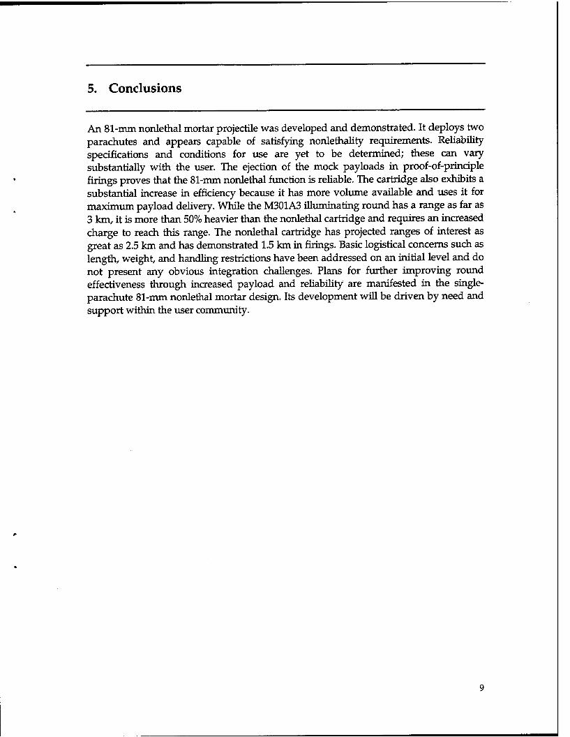
An 81-mm nonlethal mortar projectile was developed and demonstrated. It deploys two parachutes and appears capable of satisfying nonlethality requirements. Reliability specifications and conditions for use are yet to be determined; these can vary substantially with the user. The ejection of the mock payloads in proof-of-principle firings proves that the N-mm nonlethal function is reliable. The cartridge also exhibits a substantial increase in efficiency because it has more volume available and uses it for maximum payload delivery. While the M301A3 illuminating round has a range as far as 3 km, it is more than 50% heavier than the nonlethal cartridge and requires an increased charge to reach this range. The nonlethal cartridge has projected ranges of interest as great as 2.5 km and has demonstrated 1.5 km in firings. Basic logistical concerns such as length, weight, and handling restrictions have been addressed on an initial level and do not present any obvious integration challenges. Plans for further improving round effectiveness through increased payload and reliability are manifested in the single- parachute N-mm nonlethal mortar design. Its development will be driven by need and support within the user community.

,
10

References
1. Headquarters, Department of the Army, Army Ammunition Data Sheets: ArtiZZey, Ammunition, Guns, Howitzers, Mortars, Recoilless Rifles, Grenade Launchers, and Artillery Fuzes (FSC 1310, 1315, 1320, 2390), Technical Manual 43-0001-28, Washington, DC, September 2000.
2. Anderson, R., and K. Fickie, IBHVG2 - a User’s Guide, BRL-TR-2829, U.S. Army Ballistic Research Laboratory, Aberdeen Proving Ground, MD, July 1987.
3. Web site: http://www .Magicfire.com, Magicfire, Inc., Natick, MA.
11

12

13
NO. OF ORGANIZATION COPIES
1 ADMINISTRATOR DEFENSE TECHNICAL INFO CTR ATTN DTIC OCA 8725 JOHN J KINGMAN RD STE 0944 FT BELVOIR VA 22060-6218
1 DIRECTOR US ARMY RSCH LABORATORY ATTN AMSRL CI AIR REC MGMT 2800 POWDER MILL RD ADELPHI MD 20783-l 197
1 DIRECTOR US ARMY RSCH LABORATORY ATTN AMSRLCILL TECHLIB 2800 POWDER MILL RD ADELPHI MD 20783-l 197
1 DIRECTOR US ARMY RSCH LABORATORY ATTN AMSRL D D SMITH 2800 POWDER MILL RD ADELPHI MD 20783-l 197
1 COMMANDER DAHLGREN DIV ATTN CODE G61 M KELLY NAVAL SURFACE WARFARE CTR 17320 DAHLGREN ROAD DAHLGREN VA 22448-5 100
ABERDEEN PROVING GROUND
2 DIRECTOR US ARMY RSCH LABORATORY ATTN AMSRL CI LP (TECH LIB) BLDG 305 APG AA
1 CDR USATECOM ATI’N AMSTE TE F L TELETSKI RYANBLDG
1 COMMANDER USARMYABERDEENTESTCTR Al-TN STECLI BLDG400
1 COMMANDER US ARMY TACOM ARDEC A’ITN AMSTA AR FSF T J MA-l-l-S BLDG 120
1 DIR US AMSAA A-l-l-N AMXSY CA BLDG 392
NO. OF ORGANIZATION COPIES
1 DIRECTOR US ARMY RSCH LABORATORY ATTN AMSRLWMB AHORST BLDG 4600
1 DIRECTOR US ARMY RSCH LABORATORY ATTN AMSRLWMBA JCONDON BLDG 4600
5 DIRECTOR US ARMY RSCH LABORATORY ATTN AMSRL WM BC B GUIDOS
D LYON (2 CYS) J GARNER (2 CYS)
BLDG 390
2 DIRECTOR US ARMY RSCH LABORATORY ATTN AMSRL WM MB J BENDER
R KASTE BLDG 4600

INTENTIONALLYLWTBLANK
14

I
.
REPORT DOCUMENTATION PAGE Form Approved OMB No. 0704-0188
Public reporting burden for this collection of information is estimated to average 1 hour per response, including the time for reviewing instructions, searching existing data sources, gathering and maintaining the data needed, and completing and reviewing the collection of information. Send comments regarding this burden estimate or any other aspect of this collection of information, including suggestions for reducing this burden, to Washington Headquarters Services, Directorate for Information Operations and Reports, 1215 Jefferson Davis Highway, Suite 1204, Arlington, VA 22202-4302, and to the Office of Management and Budget. Paperwork Reduction Project (0704-0189). Washington, DC 20503.
1. AGENCY USE ONLY (Leave blank) 2. REPORT DATE
May 2002 4. TITLE AND SUBTITLE
Proof of Principle for an 81 -mm Nonlethal Mortar Cartridge
6. AUTHOR(S)
3. REPORT TYPE AND DATES COVERED
Final 5. FUNDING NUMBERS
Project No. 1 L 16226 18.AH80
Gamer, J.M.; Lyon, D.H. (both of ARL)
7. PERFORMING ORGANIZATION NAME(S) AND ADDRESS
U.S. Army Research Laboratory Weapons & Materials Research Directorate Aberdeen Proving Ground, MD 2 10 1 O-5066
8. PERFORMING ORGANIZATION REPORT NUMBER
3. SPONSORING/MONITORING AGENCY NAME(S) AND ADDRESS
U.S. Army Research Laboratory Weapons & Materials Research Directorate Aberdeen Proving Ground, MD 2 10 1 O-5066
Il. SUPPLEMENTARY NOTES
10. SPONSORING/MONITORING AGENCY REPORT NUMBER
ARL-MR-543
12a. DISTRIBUTION/AVAIlABILITY STATEMENT
Approved for public release; distribution is unlimited.
12b. DISTRIBUTION CODE
13. ABSTRACT (Maximum 200 words)
U.S. military forces increasingly find themselves in situations compatible with the use of nonlethal weapons. Operations other than war (OOTW) (including peacemaking, peacekeeping, and humanitarian missions) in locations such as Somalia, Haiti, Bosnia, and Kosovo repeatedly demonstrate the need for nonlethal weapons that are effective in the roles of crowd control and nondestructive area denial. This report describes the development of a nonlethal 81-mm cartridge that is ultimately viewed as a potential tool in OOTW. Payload configurations and specifications are deliberately absent since the round may have a variety of users with various desired payloads. The creation of this round initially augmented the technology developed for previous standard 81-mm mortar projectiles. The dimensions and weights of the prototype round are such that the round requires no special logistics or handling and is similar in appearance and operation to current rounds, making its employment nearly transparent to the user. Proof-of-principle testing is a logical progression from the initial concept demonstration performed in collaboration between the U.S. Army Research Laboratory and United Defense Limited Partnership. The report discusses nonlethal, 81-mm mortar projectile advancements in expulsion charge parameters and parachute deployment schemes for the prototype. An explanation is also given for the partially successful parachute deployment that occurred in the early phase. Replacement of various round components and their associated benefits are also discussed. The prototype round is intended to employ current technology and hardware with currently available components to create a reliable, cost-effective design. The round has demonstrated fimctionality and is further proposed as the test vehicle for imminent payload dispersion studies. Other evolutionary designs are also offered as vehicles for improving reliability and augmenting the proven technology described herein.
4. SUBJECT TERMS
nonlethal projectile 8 l-mm mortar cartridge
7. SECURITY CLASSIFICATION OF REPORT
Unclassified
NSN 794&ftl-29~5500
16. SECURllY CLASSIFICATION OF THIS PAGE
Unclassified
19. SECURITY CLASSIFICATION OF ABSTRACT
Unclassified
15. NUMBER OF PAGES
25 16. PRICE CODE
20. LlMlTAllON OF ABSTRACT
Standard Form 298 (Rev. 2-99) $sccfrd by ANSI Std. 239-19 15