Proof-of-Principle Experiment of a Shock-Induced ... Educational Notes/RTO-EN...Proof-of-Principle...
24
RTO-EN-AVT-185 8 - 1 Proof-of-Principle Experiment of a Shock-Induced Combustion Ramjet R.G. Veraar and A.E.H.J. Mayer TNO Defence, Security and Safety 2280 AA Rijwijk NETHERLANDS J. Verreault McGill University Montréal, QC H3A 2K6 CANADA R.A. Stowe, R. Farinaccio, P.G. Harris DRDC Valcartier Québec City, QC G3J 1X5 CANADA ABSTRACT By injecting and mixing the fuel upstream of the combustor and initiating the combustion of the fuel-air mixture by a shock wave in the combustor, shock-induced combustion ramjets offer the potential to drastically reduce the length and mass of scramjet propulsion systems. Based on extensive numerical gas dynamic and thermo-mechanical analysis, an axi-symmetric dual cone test object was designed and manufactured to demonstrate that it is possible to inject hydrogen into a high enthalpy supersonic air flow without causing premature ignition and subsequently induce combustion of this mixture by a strong oblique shock wave. The test object was instrumented with 16 thermocouples and a shadowgraph technique was used to visualize density changes in the flow field. A test series was executed in the TNO Free Jet Test Facility using the Mach 3.25 free jet nozzle in which the air flow stagnation temperature and the injected hydrogen mass flow rate was varied. Due to thermal expansion of the strut holding the test object, a small angle-of-attack was induced and resulted in different types of combustion occurring at the top and bottom sides of the test object. At the bottom, hydrogen was captured and subsequently burned in the boundary layer separation zone resulting in very high local heat loads. At the top side of the test object, shock-induced combustion occurred in the inviscid flow field only at a higher level of stagnation temperature with a peak heat load clearly downstream of the boundary layer separation zone. This experimental result is an important step in demonstrating the feasibility of a shock-induced combustion ramjet as a future hypersonic propulsion system. 1.0 INTRODUCTION In weapon system development there is a clear trend towards higher flight speed and increased range to extend tactical weapon system capabilities in terms of increased stand-off, decreased time-to-target and decreased susceptibility to countermeasures. In-service systems around the world operate in the supersonic range while technologies for hypersonic weapon systems are currently under development. Due to its superior propulsive efficiency, airbreathing propulsion is the only viable solution to satisfy the combined requirement of increased flight speed and range. Hypersonic airbreathing propulsion is therefore an important enabling technology for hypersonic weapon systems while at the same time offering significant performance improvement potential for (re-usable) space launchers. For this reason research and development activities have been carried out during the past few decades on high-speed airbreathing propulsion systems at TNO Defence, Security and Safety [1]. Numerous technology demonstration programs have been and are presently being conducted worldwide that address the challenges of hypersonic airbreathing propulsion. A significant amount of these studies focus on supersonic combustion ramjet or scramjet propulsion. In the classic (subsonic combustion) ramjet
Transcript of Proof-of-Principle Experiment of a Shock-Induced ... Educational Notes/RTO-EN...Proof-of-Principle...
RTO-EN-AVT-185 8 - 1
Proof-of-Principle Experiment of a Shock-Induced Combustion Ramjet
R.G. Veraar and A.E.H.J. Mayer TNO Defence, Security and Safety
2280 AA Rijwijk NETHERLANDS
J. Verreault McGill University
Montréal, QC H3A 2K6 CANADA
R.A. Stowe, R. Farinaccio, P.G. Harris DRDC Valcartier
Québec City, QC G3J 1X5 CANADA
ABSTRACT
By injecting and mixing the fuel upstream of the combustor and initiating the combustion of the fuel-air mixture by a shock wave in the combustor, shock-induced combustion ramjets offer the potential to drastically reduce the length and mass of scramjet propulsion systems. Based on extensive numerical gas dynamic and thermo-mechanical analysis, an axi-symmetric dual cone test object was designed and manufactured to demonstrate that it is possible to inject hydrogen into a high enthalpy supersonic air flow without causing premature ignition and subsequently induce combustion of this mixture by a strong oblique shock wave. The test object was instrumented with 16 thermocouples and a shadowgraph technique was used to visualize density changes in the flow field. A test series was executed in the TNO Free Jet Test Facility using the Mach 3.25 free jet nozzle in which the air flow stagnation temperature and the injected hydrogen mass flow rate was varied. Due to thermal expansion of the strut holding the test object, a small angle-of-attack was induced and resulted in different types of combustion occurring at the top and bottom sides of the test object. At the bottom, hydrogen was captured and subsequently burned in the boundary layer separation zone resulting in very high local heat loads. At the top side of the test object, shock-induced combustion occurred in the inviscid flow field only at a higher level of stagnation temperature with a peak heat load clearly downstream of the boundary layer separation zone. This experimental result is an important step in demonstrating the feasibility of a shock-induced combustion ramjet as a future hypersonic propulsion system.
1.0 INTRODUCTION
In weapon system development there is a clear trend towards higher flight speed and increased range to extend tactical weapon system capabilities in terms of increased stand-off, decreased time-to-target and decreased susceptibility to countermeasures. In-service systems around the world operate in the supersonic range while technologies for hypersonic weapon systems are currently under development. Due to its superior propulsive efficiency, airbreathing propulsion is the only viable solution to satisfy the combined requirement of increased flight speed and range. Hypersonic airbreathing propulsion is therefore an important enabling technology for hypersonic weapon systems while at the same time offering significant performance improvement potential for (re-usable) space launchers. For this reason research and development activities have been carried out during the past few decades on high-speed airbreathing propulsion systems at TNO Defence, Security and Safety [1].
Numerous technology demonstration programs have been and are presently being conducted worldwide that address the challenges of hypersonic airbreathing propulsion. A significant amount of these studies focus on supersonic combustion ramjet or scramjet propulsion. In the classic (subsonic combustion) ramjet
Proof-of-Principle Experiment of a Shock-Induced Combustion Ramjet
8 - 2 RTO-EN-AVT-185
engine, the compression process in the air intake reduces the flow speed to subsonic values prior to injecting and burning the fuel. At flight Mach numbers around 6, the temperature of the compressed air becomes so high that combustion of the fuel results in a large part of the chemical energy of the fuel being lost due to dissociation of the combustion products. An option to reduce these dissociation losses is to reduce the combustor entry static temperature by limiting the compression ratio and allowing the air to enter the combustor at supersonic flow speeds. The resulting scramjet engine cycle can potentially be used to generate useful thrust at flight speeds well into the hypersonic regime. However, the supersonic flow speed in the combustor of a scramjet engine in turn poses severe challenges related to injection, mixing and combustion of the fuel within the combustor. To efficiently realize this in a supersonic flow may require a significant combustor length which adds considerably to the vehicle mass and complexity, especially considering the fact that active cooling may be required for the combustor walls.
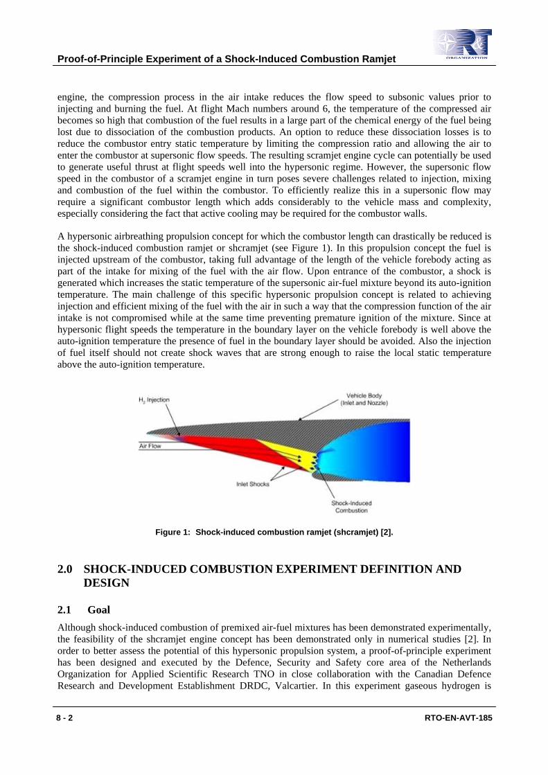
A hypersonic airbreathing propulsion concept for which the combustor length can drastically be reduced is the shock-induced combustion ramjet or shcramjet (see Figure 1). In this propulsion concept the fuel is injected upstream of the combustor, taking full advantage of the length of the vehicle forebody acting as part of the intake for mixing of the fuel with the air flow. Upon entrance of the combustor, a shock is generated which increases the static temperature of the supersonic air-fuel mixture beyond its auto-ignition temperature. The main challenge of this specific hypersonic propulsion concept is related to achieving injection and efficient mixing of the fuel with the air in such a way that the compression function of the air intake is not compromised while at the same time preventing premature ignition of the mixture. Since at hypersonic flight speeds the temperature in the boundary layer on the vehicle forebody is well above the auto-ignition temperature the presence of fuel in the boundary layer should be avoided. Also the injection of fuel itself should not create shock waves that are strong enough to raise the local static temperature above the auto-ignition temperature.
Figure 1: Shock-induced combustion ramjet (shcramjet) [2].
2.0 SHOCK-INDUCED COMBUSTION EXPERIMENT DEFINITION AND DESIGN
2.1 Goal Although shock-induced combustion of premixed air-fuel mixtures has been demonstrated experimentally, the feasibility of the shcramjet engine concept has been demonstrated only in numerical studies [2]. In order to better assess the potential of this hypersonic propulsion system, a proof-of-principle experiment has been designed and executed by the Defence, Security and Safety core area of the Netherlands Organization for Applied Scientific Research TNO in close collaboration with the Canadian Defence Research and Development Establishment DRDC, Valcartier. In this experiment gaseous hydrogen is
Proof-of-Principle Experiment of a Shock-Induced Combustion Ramjet
RTO-EN-AVT-185 8 - 3
injected from a test object into a supersonic air flow having a static temperature which is representative for typical hypersonic operational conditions. Figure 2 displays the axi-symmetrical test object. After mixing with the air over a certain distance the air-fuel mixture flows through a strong oblique shock wave generated by the test object itself. The objective of this experiment is to demonstrate that it is possible to inject a highly reactive fuel into a high enthalpy supersonic air flow without causing premature ignition and subsequently induce combustion of this mixture by a strong oblique shock wave.
Figure 2: Schematic of the test geometry and expected flow field.
2.2 Gas Dynamic and Thermo-Mechanic Design of the Test Object Computational Fluid Dynamics (CFD) was extensively used to design a shock-induced combustion experiment in which hydrogen was injected from the nose of a dual-cone test object into a supersonic airstream. Given the operational envelope and the dimensional constraints of the TNO Free Jet Test Facility [3] (see Section 2.5.1) it was decided to design an axi-symmetric test object having a second cone base diameter of roughly 60 mm. A half cone angle of 5° was selected for the upstream slender cone part while the half cone angle of the second cone was to be determined from gas dynamic analysis. Several test object geometries, fuel injectors, and test conditions were considered to identify feasible possibilities. This section gives an overview of the gas dynamic and thermo-mechanic design activities performed.
2.2.1 Gas Dynamic Analysis
In an extensive computational study [4, 5] using FLUENT [6] different injector geometries were investigated and compared based on four performance parameters: the fuel penetration height, the mixing efficiency, the Mach number downstream of the injector and the suppression of premature ignition. The following types of injectors have been considered, assuming the hydrogen to be injected at sonic flow conditions:
• Dump injector.
• Dual stage injector.
• Cylindrical ramp injector.
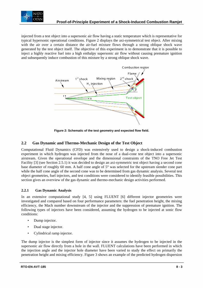
The dump injector is the simplest form of injector since it assumes the hydrogen to be injected in the supersonic air flow directly from a hole in the wall. FLUENT calculations have been performed in which the injection angle and the injector hole diameter have been varied to study the effect on primarily the penetration height and mixing efficiency. Figure 3 shows an example of the predicted hydrogen dispersion
Proof-of-Principle Experiment of a Shock-Induced Combustion Ramjet
8 - 4 RTO-EN-AVT-185
for this kind of injector. As can be seen in this figure, hydrogen is inevitably captured inside the boundary layer. Given the very high temperatures inside the boundary layer (well beyond 1000 K) this will consequently result in premature ignition of the hydrogen.
Figure 3: Hydrogen mole fraction contours for a typical dump injector configuration.
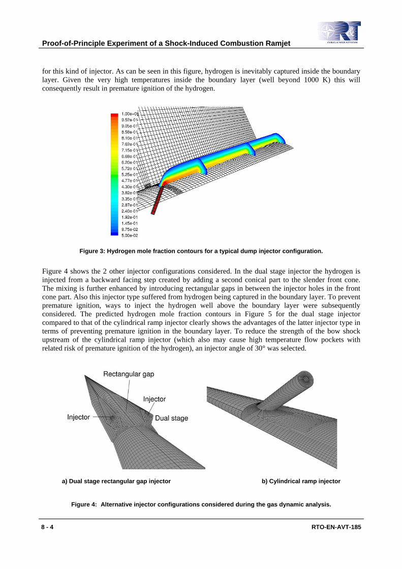
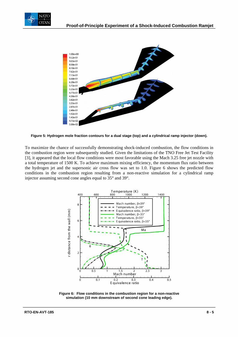
Figure 4 shows the 2 other injector configurations considered. In the dual stage injector the hydrogen is injected from a backward facing step created by adding a second conical part to the slender front cone. The mixing is further enhanced by introducing rectangular gaps in between the injector holes in the front cone part. Also this injector type suffered from hydrogen being captured in the boundary layer. To prevent premature ignition, ways to inject the hydrogen well above the boundary layer were subsequently considered. The predicted hydrogen mole fraction contours in Figure 5 for the dual stage injector compared to that of the cylindrical ramp injector clearly shows the advantages of the latter injector type in terms of preventing premature ignition in the boundary layer. To reduce the strength of the bow shock upstream of the cylindrical ramp injector (which also may cause high temperature flow pockets with related risk of premature ignition of the hydrogen), an injector angle of 30° was selected.
a) Dual stage rectangular gap injector b) Cylindrical ramp injector
Figure 4: Alternative injector configurations considered during the gas dynamic analysis.
Proof-of-Principle Experiment of a Shock-Induced Combustion Ramjet
RTO-EN-AVT-185 8 - 5
Figure 5: Hydrogen mole fraction contours for a dual stage (top) and a cylindrical ramp injector (down).
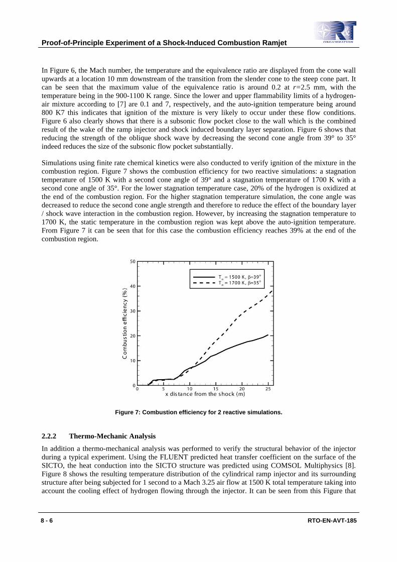
To maximize the chance of successfully demonstrating shock-induced combustion, the flow conditions in the combustion region were subsequently studied. Given the limitations of the TNO Free Jet Test Facility [3], it appeared that the local flow conditions were most favorable using the Mach 3.25 free jet nozzle with a total temperature of 1500 K. To achieve maximum mixing efficiency, the momentum flux ratio between the hydrogen jet and the supersonic air cross flow was set to 1.0. Figure 6 shows the predicted flow conditions in the combustion region resulting from a non-reactive simulation for a cylindrical ramp injector assuming second cone angles equal to 35° and 39°.
Figure 6: Flow conditions in the combustion region for a non-reactive simulation (10 mm downstream of second cone leading edge).
Proof-of-Principle Experiment of a Shock-Induced Combustion Ramjet
8 - 6 RTO-EN-AVT-185
In Figure 6, the Mach number, the temperature and the equivalence ratio are displayed from the cone wall upwards at a location 10 mm downstream of the transition from the slender cone to the steep cone part. It can be seen that the maximum value of the equivalence ratio is around 0.2 at r=2.5 mm, with the temperature being in the 900-1100 K range. Since the lower and upper flammability limits of a hydrogen-air mixture according to [7] are 0.1 and 7, respectively, and the auto-ignition temperature being around 800 K7 this indicates that ignition of the mixture is very likely to occur under these flow conditions. Figure 6 also clearly shows that there is a subsonic flow pocket close to the wall which is the combined result of the wake of the ramp injector and shock induced boundary layer separation. Figure 6 shows that reducing the strength of the oblique shock wave by decreasing the second cone angle from 39° to 35° indeed reduces the size of the subsonic flow pocket substantially.
Simulations using finite rate chemical kinetics were also conducted to verify ignition of the mixture in the combustion region. Figure 7 shows the combustion efficiency for two reactive simulations: a stagnation temperature of 1500 K with a second cone angle of 39° and a stagnation temperature of 1700 K with a second cone angle of 35°. For the lower stagnation temperature case, 20% of the hydrogen is oxidized at the end of the combustion region. For the higher stagnation temperature simulation, the cone angle was decreased to reduce the second cone angle strength and therefore to reduce the effect of the boundary layer / shock wave interaction in the combustion region. However, by increasing the stagnation temperature to 1700 K, the static temperature in the combustion region was kept above the auto-ignition temperature. From Figure 7 it can be seen that for this case the combustion efficiency reaches 39% at the end of the combustion region.
Figure 7: Combustion efficiency for 2 reactive simulations.
2.2.2 Thermo-Mechanic Analysis
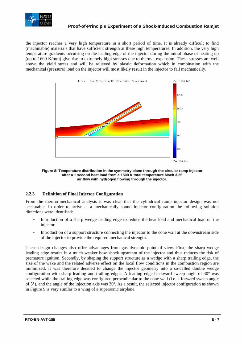
In addition a thermo-mechanical analysis was performed to verify the structural behavior of the injector during a typical experiment. Using the FLUENT predicted heat transfer coefficient on the surface of the SICTO, the heat conduction into the SICTO structure was predicted using COMSOL Multiphysics [8]. Figure 8 shows the resulting temperature distribution of the cylindrical ramp injector and its surrounding structure after being subjected for 1 second to a Mach 3.25 air flow at 1500 K total temperature taking into account the cooling effect of hydrogen flowing through the injector. It can be seen from this Figure that
Proof-of-Principle Experiment of a Shock-Induced Combustion Ramjet
RTO-EN-AVT-185 8 - 7
the injector reaches a very high temperature in a short period of time. It is already difficult to find (machinable) materials that have sufficient strength at these high temperatures. In addition, the very high temperature gradients occurring on the leading edge of the injector during the initial phase of heating up (up to 1600 K/mm) give rise to extremely high stresses due to thermal expansion. These stresses are well above the yield stress and will be relieved by plastic deformation which in combination with the mechanical (pressure) load on the injector will most likely result in the injector to fail mechanically.
Figure 8: Temperature distribution in the symmetry plane through the circular ramp injector after a 1 second heat load from a 1500 K total temperature Mach 3.25
air flow with hydrogen flowing through the injector.
2.2.3 Definition of Final Injector Configuration
From the thermo-mechanical analysis it was clear that the cylindrical ramp injector design was not acceptable. In order to arrive at a mechanically sound injector configuration the following solution directions were identified:
• Introduction of a sharp wedge leading edge to reduce the heat load and mechanical load on the injector.
• Introduction of a support structure connecting the injector to the cone wall at the downstream side of the injector to provide the required mechanical strength.
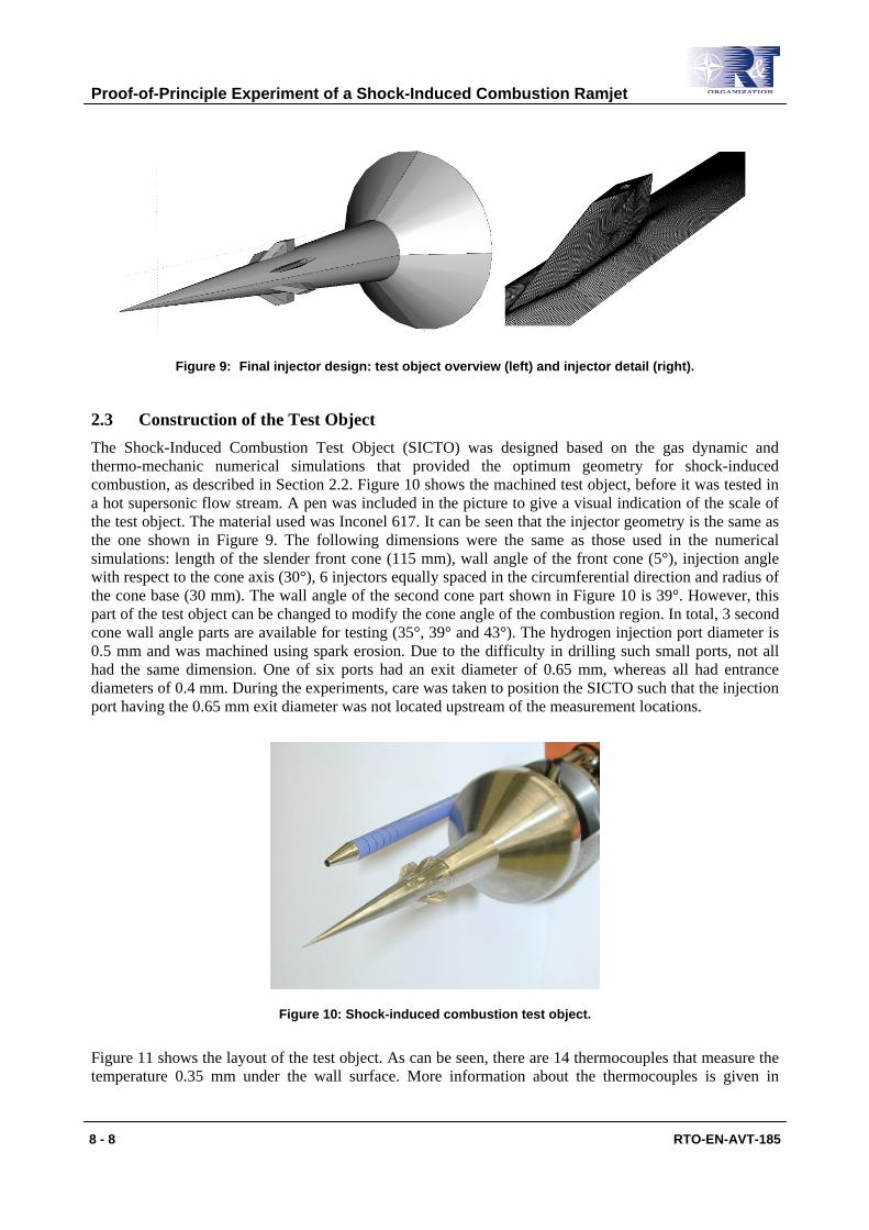
These design changes also offer advantages from gas dynamic point of view. First, the sharp wedge leading edge results in a much weaker bow shock upstream of the injector and thus reduces the risk of premature ignition. Secondly, by shaping the support structure as a wedge with a sharp trailing edge, the size of the wake and the related adverse effect on the local flow conditions in the combustion region are minimized. It was therefore decided to change the injector geometry into a so-called double wedge configuration with sharp leading and trailing edges. A leading edge backward sweep angle of 30° was selected while the trailing edge was configured perpendicular to the cone wall (i.e. a forward sweep angle of 5°), and the angle of the injection axis was 30º. As a result, the selected injector configuration as shown in Figure 9 is very similar to a wing of a supersonic airplane.
Proof-of-Principle Experiment of a Shock-Induced Combustion Ramjet
8 - 8 RTO-EN-AVT-185
Figure 9: Final injector design: test object overview (left) and injector detail (right).
2.3 Construction of the Test Object The Shock-Induced Combustion Test Object (SICTO) was designed based on the gas dynamic and thermo-mechanic numerical simulations that provided the optimum geometry for shock-induced combustion, as described in Section 2.2. Figure 10 shows the machined test object, before it was tested in a hot supersonic flow stream. A pen was included in the picture to give a visual indication of the scale of the test object. The material used was Inconel 617. It can be seen that the injector geometry is the same as the one shown in Figure 9. The following dimensions were the same as those used in the numerical simulations: length of the slender front cone (115 mm), wall angle of the front cone (5°), injection angle with respect to the cone axis (30°), 6 injectors equally spaced in the circumferential direction and radius of the cone base (30 mm). The wall angle of the second cone part shown in Figure 10 is 39°. However, this part of the test object can be changed to modify the cone angle of the combustion region. In total, 3 second cone wall angle parts are available for testing (35°, 39° and 43°). The hydrogen injection port diameter is 0.5 mm and was machined using spark erosion. Due to the difficulty in drilling such small ports, not all had the same dimension. One of six ports had an exit diameter of 0.65 mm, whereas all had entrance diameters of 0.4 mm. During the experiments, care was taken to position the SICTO such that the injection port having the 0.65 mm exit diameter was not located upstream of the measurement locations.
Figure 10: Shock-induced combustion test object.
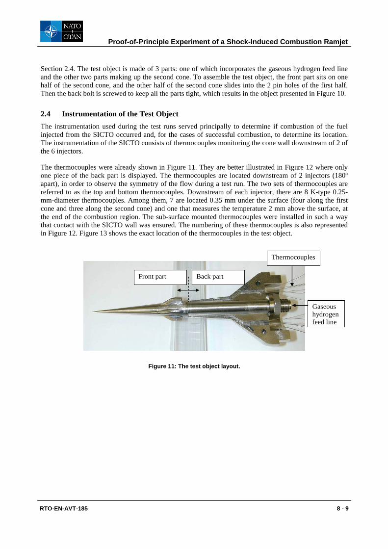
Figure 11 shows the layout of the test object. As can be seen, there are 14 thermocouples that measure the temperature 0.35 mm under the wall surface. More information about the thermocouples is given in
Proof-of-Principle Experiment of a Shock-Induced Combustion Ramjet
RTO-EN-AVT-185 8 - 9
Section 2.4. The test object is made of 3 parts: one of which incorporates the gaseous hydrogen feed line and the other two parts making up the second cone. To assemble the test object, the front part sits on one half of the second cone, and the other half of the second cone slides into the 2 pin holes of the first half. Then the back bolt is screwed to keep all the parts tight, which results in the object presented in Figure 10.
2.4 Instrumentation of the Test Object The instrumentation used during the test runs served principally to determine if combustion of the fuel injected from the SICTO occurred and, for the cases of successful combustion, to determine its location. The instrumentation of the SICTO consists of thermocouples monitoring the cone wall downstream of 2 of the 6 injectors.
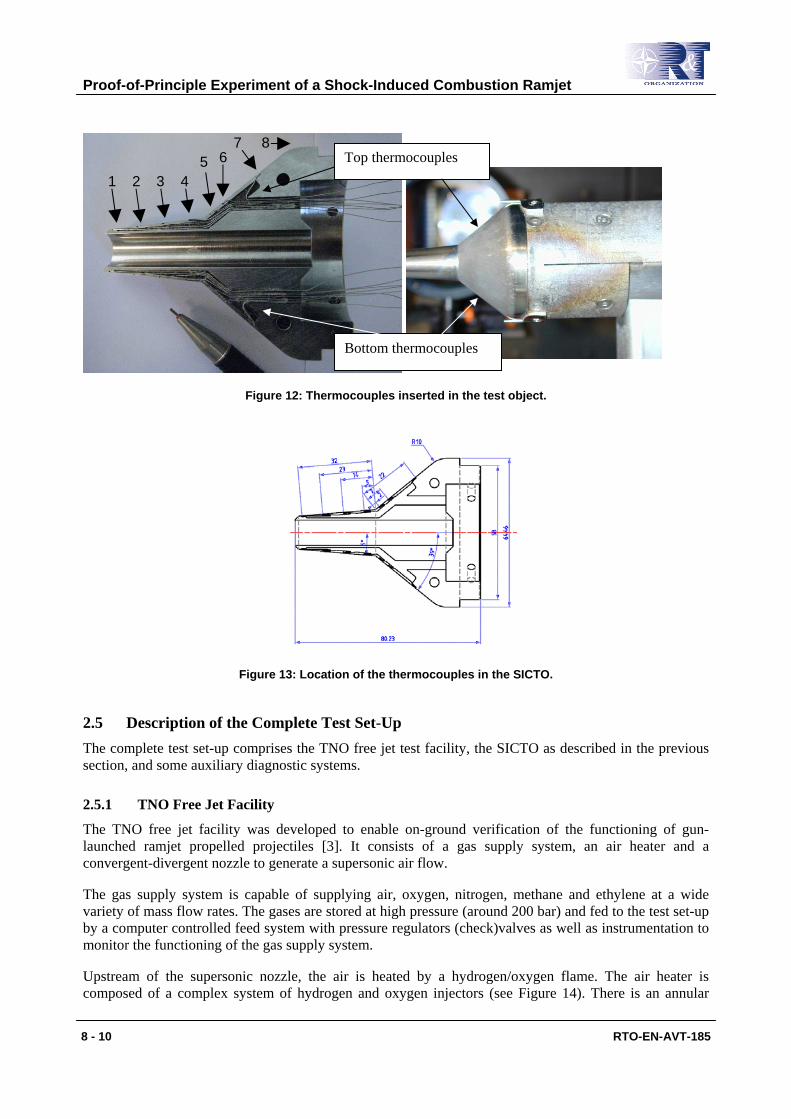
The thermocouples were already shown in Figure 11. They are better illustrated in Figure 12 where only one piece of the back part is displayed. The thermocouples are located downstream of 2 injectors (180º apart), in order to observe the symmetry of the flow during a test run. The two sets of thermocouples are referred to as the top and bottom thermocouples. Downstream of each injector, there are 8 K-type 0.25-mm-diameter thermocouples. Among them, 7 are located 0.35 mm under the surface (four along the first cone and three along the second cone) and one that measures the temperature 2 mm above the surface, at the end of the combustion region. The sub-surface mounted thermocouples were installed in such a way that contact with the SICTO wall was ensured. The numbering of these thermocouples is also represented in Figure 12. Figure 13 shows the exact location of the thermocouples in the test object.
Figure 11: The test object layout.
Thermocouples
Front part Back part
Gaseous hydrogen feed line
Proof-of-Principle Experiment of a Shock-Induced Combustion Ramjet
8 - 10 RTO-EN-AVT-185
Figure 12: Thermocouples inserted in the test object.
Figure 13: Location of the thermocouples in the SICTO.
2.5 Description of the Complete Test Set-Up The complete test set-up comprises the TNO free jet test facility, the SICTO as described in the previous section, and some auxiliary diagnostic systems.
2.5.1 TNO Free Jet Facility
The TNO free jet facility was developed to enable on-ground verification of the functioning of gun-launched ramjet propelled projectiles [3]. It consists of a gas supply system, an air heater and a convergent-divergent nozzle to generate a supersonic air flow.
The gas supply system is capable of supplying air, oxygen, nitrogen, methane and ethylene at a wide variety of mass flow rates. The gases are stored at high pressure (around 200 bar) and fed to the test set-up by a computer controlled feed system with pressure regulators (check)valves as well as instrumentation to monitor the functioning of the gas supply system.
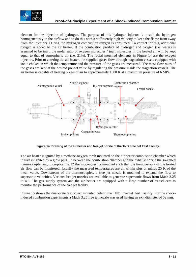
Upstream of the supersonic nozzle, the air is heated by a hydrogen/oxygen flame. The air heater is composed of a complex system of hydrogen and oxygen injectors (see Figure 14). There is an annular
1 2 3 4 5 6
7 8 Top thermocouples
Bottom thermocouples
Proof-of-Principle Experiment of a Shock-Induced Combustion Ramjet
RTO-EN-AVT-185 8 - 11
element for the injection of hydrogen. The purpose of this hydrogen injector is to add the hydrogen homogeneously to the airflow and to do this with a sufficiently high velocity to keep the flame front away from the injectors. During the hydrogen combustion oxygen is consumed. To correct for this, additional oxygen is added to the air heater. If the combustion product of hydrogen and oxygen (i.e. water) is assumed to be inert, the molar ratio of oxygen molecules / inert molecules in the heated air will be kept equal to that of atmospheric air (i.e. 21%). The radial mounted elements in Figure 14 are the oxygen injectors. Prior to entering the air heater, the supplied gases flow through stagnation vessels equipped with sonic chokes in which the temperature and the pressure of the gases are measured. The mass flow rates of the gases are kept at the desired pre-set value by regulating the pressure inside the stagnation vessels. The air heater is capable of heating 5 kg/s of air to approximately 1500 K at a maximum pressure of 6 MPa.
Air stagnation vessel Nozzle segment Combustion chamber
segment
Brake-up dome
Injector segment
Oxygen injector Hydrogen injector
Thermocouple ring
Freejet nozzle
Figure 14: Drawing of the air heater and free jet nozzle of the TNO Free Jet Test Facility.
The air heater is ignited by a methane-oxygen torch mounted on the air heater combustion chamber which in turn is ignited by a glow plug. In between the combustion chamber and the exhaust nozzle the so-called thermocouple ring, incorporating 12 thermocouples, is mounted such that the homogeneity of the heated air flow can be monitored. Usually the measured temperatures are all within plus or minus 25 K of the mean value. Downstream of the thermocouples, a free jet nozzle is mounted to expand the flow to supersonic velocities. Various free jet nozzles are available to generate supersonic flows from Mach 3.25 to 4.5. The gas supply system and the air heater are equipped with a large number of transducers to monitor the performance of the free jet facility.
Figure 15 shows the dual-cone test object mounted behind the TNO Free Jet Test Facility. For the shock-induced combustion experiments a Mach 3.25 free jet nozzle was used having an exit diameter of 52 mm.
Proof-of-Principle Experiment of a Shock-Induced Combustion Ramjet
8 - 12 RTO-EN-AVT-185
Figure 15: Dual-cone test object mounted behind the TNO free jet test facility.
2.5.2 Auxiliary Diagnostic Systems
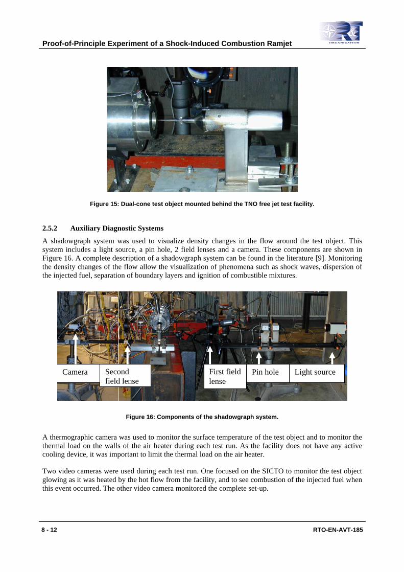
A shadowgraph system was used to visualize density changes in the flow around the test object. This system includes a light source, a pin hole, 2 field lenses and a camera. These components are shown in Figure 16. A complete description of a shadowgraph system can be found in the literature [9]. Monitoring the density changes of the flow allow the visualization of phenomena such as shock waves, dispersion of the injected fuel, separation of boundary layers and ignition of combustible mixtures.
Light source Pin hole First field lense
Second field lense
Camera
Figure 16: Components of the shadowgraph system.
A thermographic camera was used to monitor the surface temperature of the test object and to monitor the thermal load on the walls of the air heater during each test run. As the facility does not have any active cooling device, it was important to limit the thermal load on the air heater.
Two video cameras were used during each test run. One focused on the SICTO to monitor the test object glowing as it was heated by the hot flow from the facility, and to see combustion of the injected fuel when this event occurred. The other video camera monitored the complete set-up.
Proof-of-Principle Experiment of a Shock-Induced Combustion Ramjet
RTO-EN-AVT-185 8 - 13
3.0 EXPERIMENTAL RESULTS
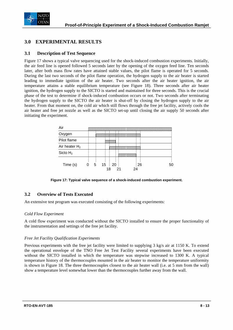
3.1 Description of Test Sequence Figure 17 shows a typical valve sequencing used for the shock-induced combustion experiments. Initially, the air feed line is opened followed 5 seconds later by the opening of the oxygen feed line. Ten seconds later, after both mass flow rates have attained stable values, the pilot flame is operated for 5 seconds. During the last two seconds of the pilot flame operation, the hydrogen supply to the air heater is started leading to immediate ignition of the air heater. Two seconds after the air heater ignition, the air temperature attains a stable equilibrium temperature (see Figure 18). Three seconds after air heater ignition, the hydrogen supply to the SICTO is started and maintained for three seconds. This is the crucial phase of the test to determine if shock-induced combustion occurs or not. Two seconds after terminating the hydrogen supply to the SICTO the air heater is shut-off by closing the hydrogen supply to the air heater. From that moment on, the cold air which still flows through the free jet facility, actively cools the air heater and free jet nozzle as well as the SICTO set-up until closing the air supply 50 seconds after initiating the experiment.
Air Oxygen Pilot flame Air heater H2
0 5 15 18
20 26 50 Time (s) 21 24
Sicto H2
Figure 17: Typical valve sequence of a shock-induced combustion experiment.
3.2 Overview of Tests Executed An extensive test program was executed consisting of the following experiments:
Cold Flow Experiment
A cold flow experiment was conducted without the SICTO installed to ensure the proper functionality of the instrumentation and settings of the free jet facility.
Free Jet Facility Qualification Experiments
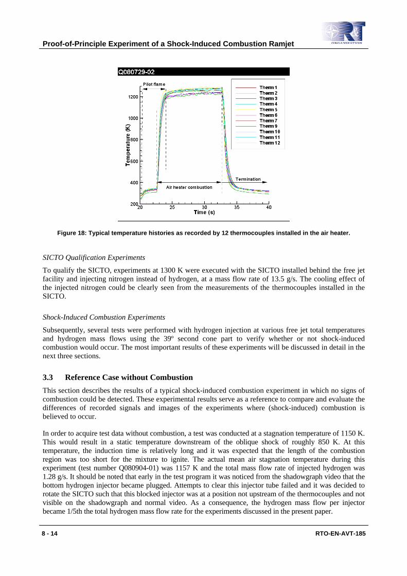
Previous experiments with the free jet facility were limited to supplying 3 kg/s air at 1150 K. To extend the operational envelope of the TNO Free Jet Test Facility several experiments have been executed without the SICTO installed in which the temperature was stepwise increased to 1300 K. A typical temperature history of the thermocouples mounted in the air heater to monitor the temperature uniformity is shown in Figure 18. The three thermocouples closest to the air heater wall (i.e. at 5 mm from the wall) show a temperature level somewhat lower than the thermocouples further away from the wall.
Proof-of-Principle Experiment of a Shock-Induced Combustion Ramjet
8 - 14 RTO-EN-AVT-185
Figure 18: Typical temperature histories as recorded by 12 thermocouples installed in the air heater.
SICTO Qualification Experiments
To qualify the SICTO, experiments at 1300 K were executed with the SICTO installed behind the free jet facility and injecting nitrogen instead of hydrogen, at a mass flow rate of 13.5 g/s. The cooling effect of the injected nitrogen could be clearly seen from the measurements of the thermocouples installed in the SICTO.
Shock-Induced Combustion Experiments
Subsequently, several tests were performed with hydrogen injection at various free jet total temperatures and hydrogen mass flows using the 39º second cone part to verify whether or not shock-induced combustion would occur. The most important results of these experiments will be discussed in detail in the next three sections.
3.3 Reference Case without Combustion This section describes the results of a typical shock-induced combustion experiment in which no signs of combustion could be detected. These experimental results serve as a reference to compare and evaluate the differences of recorded signals and images of the experiments where (shock-induced) combustion is believed to occur.
In order to acquire test data without combustion, a test was conducted at a stagnation temperature of 1150 K. This would result in a static temperature downstream of the oblique shock of roughly 850 K. At this temperature, the induction time is relatively long and it was expected that the length of the combustion region was too short for the mixture to ignite. The actual mean air stagnation temperature during this experiment (test number Q080904-01) was 1157 K and the total mass flow rate of injected hydrogen was 1.28 g/s. It should be noted that early in the test program it was noticed from the shadowgraph video that the bottom hydrogen injector became plugged. Attempts to clear this injector tube failed and it was decided to rotate the SICTO such that this blocked injector was at a position not upstream of the thermocouples and not visible on the shadowgraph and normal video. As a consequence, the hydrogen mass flow per injector became 1/5th the total hydrogen mass flow rate for the experiments discussed in the present paper.
Proof-of-Principle Experiment of a Shock-Induced Combustion Ramjet
RTO-EN-AVT-185 8 - 15
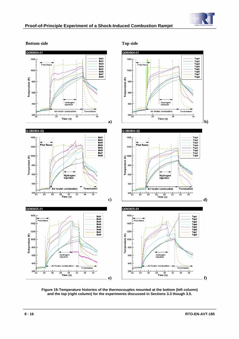
Figure 19 a) and b) show the temperature histories of the thermocouples at the lower and top sides of the SICTO, respectively. At both the top and bottom side of the SICTO the thermocouple signals show very similar behavior. At the moment of ignition of the pilot flame of the air heater all thermocouples show a small increase in measured temperature. Upon air heater ignition all measured temperatures rise very quickly showing a clear distinction between the thermocouples mounted on the slender upstream cone and those that are mounted on the steep aft cone. The local temperature-time gradients are a good measure for the local heat loads; the higher the temperature-time gradient, the higher the heat load. The slender cone thermocouples (numbers 1 through 4) experience a modest heat load and those that are mounted on the steep second cone (numbers 5 through 7) encounter a much higher heat load due to the increased temperature level of the supersonic flow downstream of the strong oblique shock wave. Thermocouple number 8 is mounted at the aft side of the second cone 2 mm above the surface in order to measure the local flow temperature (see Figure 12). The cooling effect of the injected hydrogen can be clearly seen on all signals of the thermocouples mounted on the second cone as well as the thermocouple mounted in the air flow downstream of the combustion zone. No signs of combustion can be noticed. Directly after the hydrogen injection phase the temperatures measured by thermocouples 5 through 8 rise again until the air heater is terminated.
Proof-of-Principle Experiment of a Shock-Induced Combustion Ramjet
8 - 16 RTO-EN-AVT-185
Bottom side Top side
a) b)
c) d)
e) f)
Figure 19: Temperature histories of the thermocouples mounted at the bottom (left column) and the top (right column) for the experiments discussed in Sections 3.3 though 3.5.
Proof-of-Principle Experiment of a Shock-Induced Combustion Ramjet
RTO-EN-AVT-185 8 - 17
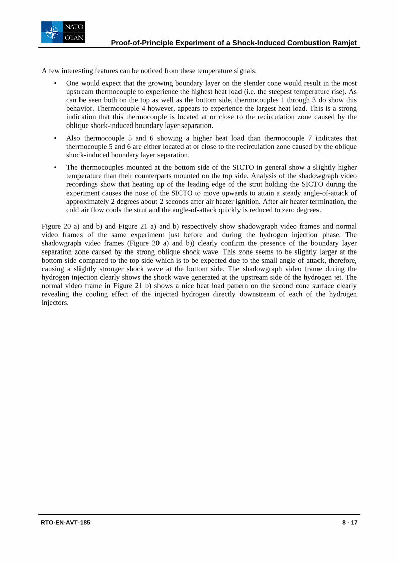
A few interesting features can be noticed from these temperature signals:
• One would expect that the growing boundary layer on the slender cone would result in the most upstream thermocouple to experience the highest heat load (i.e. the steepest temperature rise). As can be seen both on the top as well as the bottom side, thermocouples 1 through 3 do show this behavior. Thermocouple 4 however, appears to experience the largest heat load. This is a strong indication that this thermocouple is located at or close to the recirculation zone caused by the oblique shock-induced boundary layer separation.
• Also thermocouple 5 and 6 showing a higher heat load than thermocouple 7 indicates that thermocouple 5 and 6 are either located at or close to the recirculation zone caused by the oblique shock-induced boundary layer separation.
• The thermocouples mounted at the bottom side of the SICTO in general show a slightly higher temperature than their counterparts mounted on the top side. Analysis of the shadowgraph video recordings show that heating up of the leading edge of the strut holding the SICTO during the experiment causes the nose of the SICTO to move upwards to attain a steady angle-of-attack of approximately 2 degrees about 2 seconds after air heater ignition. After air heater termination, the cold air flow cools the strut and the angle-of-attack quickly is reduced to zero degrees.
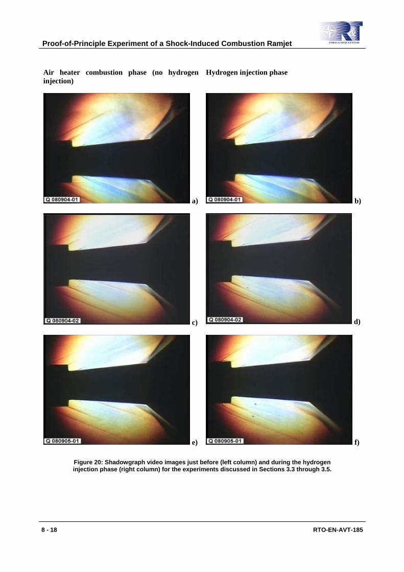
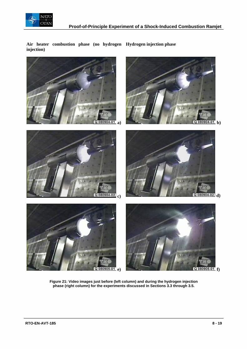
Figure 20 a) and b) and Figure 21 a) and b) respectively show shadowgraph video frames and normal video frames of the same experiment just before and during the hydrogen injection phase. The shadowgraph video frames (Figure 20 a) and b)) clearly confirm the presence of the boundary layer separation zone caused by the strong oblique shock wave. This zone seems to be slightly larger at the bottom side compared to the top side which is to be expected due to the small angle-of-attack, therefore, causing a slightly stronger shock wave at the bottom side. The shadowgraph video frame during the hydrogen injection clearly shows the shock wave generated at the upstream side of the hydrogen jet. The normal video frame in Figure 21 b) shows a nice heat load pattern on the second cone surface clearly revealing the cooling effect of the injected hydrogen directly downstream of each of the hydrogen injectors.
Proof-of-Principle Experiment of a Shock-Induced Combustion Ramjet
8 - 18 RTO-EN-AVT-185
Air heater combustion phase (no hydrogen injection)
Hydrogen injection phase
a) b)
c) d)
e) f)
Figure 20: Shadowgraph video images just before (left column) and during the hydrogen injection phase (right column) for the experiments discussed in Sections 3.3 through 3.5.
Proof-of-Principle Experiment of a Shock-Induced Combustion Ramjet
RTO-EN-AVT-185 8 - 19
Air heater combustion phase (no hydrogen injection)
Hydrogen injection phase
a) b)
c) d)
e) f)
Figure 21: Video images just before (left column) and during the hydrogen injection phase (right column) for the experiments discussed in Sections 3.3 through 3.5.
Proof-of-Principle Experiment of a Shock-Induced Combustion Ramjet
8 - 20 RTO-EN-AVT-185
3.4 Combustion in Shock-Wave Induced Boundary Layer Separation Zone The experiment as described in the previous section was repeated with an actual mean stagnation temperature of the air flow equal to 1254 K (test number Q080904-02). The total hydrogen mass flow rate injected again was 1.28 g/s. The temperature histories of the bottom and top thermocouples are shown in Figures 19 c) and d), respectively. Comparing Figure 19 d) with Figure 19 b) shows that the temperature histories of the top thermocouples of this experiment are very similar to those of the reference experiment. The higher stagnation temperature with respect to the reference experiment causes all recorded temperatures to be higher. Also in this experiment the cooling effect of the injected hydrogen can be noticed on the top thermocouples 5 through 8. An important difference with respect to the reference experiment is that upon air heater ignition, the heat load (i.e. the temperature-time gradient) at position 4 (both top and bottom) is now significantly higher than those at position 1 through 3. This may indicate an increased size of the boundary layer separation zone. This indeed is confirmed by the shadowgraph video images when comparing Figures 20 c) and a). Especially at the bottom side, the boundary layer separation zone is clearly larger than for the reference experiment.
When looking at the temperature histories on the bottom side in Figure 19 c) it can be seen that 4 thermocouples show a gradual increase of temperature during the hydrogen injection phase and a sudden temperature decrease at termination of the hydrogen injection. At the end of the hydrogen injection phase thermocouple 6 even measures a wall temperature around 1300 K, which is in excess of the stagnation temperature of the supersonic air flow. This is an effect that can only be attributed to the occurrence of combustion. It can be seen that these temperature effects are most pronounced for thermocouples 5 and 6. In contrast to thermocouples 7 and 8, which do not seem to experience an increased temperature during the hydrogen injection phase, the effect of combustion is also visible on thermocouple 4 and, although with a significant time delay presumably caused by conduction of heat in the upstream direction, even on thermocouple 3. This is a strong indication that combustion occurs only in the boundary layer separation zone which then is accompanied by a substantial increase of the size of the boundary layer separation zone. This would be due to a decreased flow density resulting from the combustion heat added. When looking at the shadowgraph image of the hydrogen injection phase of this experiment (Figure 20 d)) it can be seen that the separation zone at the bottom side indeed is significantly enlarged compared to the situation prior to hydrogen injection in the same experiment (Figure 20 c)). In contrast, the separation zone at the top side is of comparable size as in the situation prior to hydrogen injection. Finally, when looking at the normal video frame during the hydrogen injection phase depicted in Figure 21 d), the flow field at the bottom of the SICTO features a vague hazy plume just below the second cone surface. From the above information it is concluded that the small angle-of-attack of the SICTO results in hydrogen to be captured inside the boundary layer separation zone. The low flow velocity inside this boundary layer separation zone results in a high static temperature combined with a residence time of the gases long enough for combustion to initiate. At the top side there are no indications of combustion occurring and it is assumed that due to the small angle-of-attack either no hydrogen is captured in the boundary layer separation zone or the combination of static temperature and residence time inside the separation zone are unfavorable for the hydrogen to be oxidized.
3.5 Shock-Induced Combustion in Inviscid Flow Field The experiment as described in the previous section was repeated with an actual mean stagnation temperature of the air flow equal to 1428 K (test number Q080905-01). The total hydrogen mass flow rate injected again was 1.28 g/s. The temperature histories of the bottom and top thermocouples are shown in Figures 19 e) and f), respectively. Looking at the bottom thermocouple recordings in Figure 19 e) it can be seen clearly that combustion is occurring; thermocouples 4 through 8 show a steep temperature gradient upon hydrogen injection. The hazy plume visible below the second cone surface on the normal video image (Figure 21 f)) also confirms that combustion occurs at the bottom side of the SICTO. In contrast to the experiment described in the previous section, the combustion seems to be initiated immediately upon
Proof-of-Principle Experiment of a Shock-Induced Combustion Ramjet
RTO-EN-AVT-185 8 - 21
hydrogen injection. Thermocouples 5, 6 and 8 record maximum temperatures in excess of the air flow stagnation temperature. Close to the end of the hydrogen injection phase and prior to its failure, thermocouple 6 records a wall temperature approaching 1600 K. The largest temperature gradient is recorded by thermocouples 4 through 6 indicating that the heat load occurring at these locations is the largest. As in the experiment described in the previous section thermocouple 3 shows an increasing temperature with a significant time delay which is believed to be the result of heat conduction in the upstream direction from the thermally highly loaded boundary layer separation zone. Thermocouple 7 shows a temperature gradient which is significantly lower than that of thermocouples 4 through 6. As in the experiment described in the previous section, these temperature histories indicate that combustion is occurring mainly inside the boundary layer separation zone. The shadowgraph image in Figure 20 f) indeed shows that the size of the boundary layer separation zone at the bottom side has become even larger than in the experiment described in the previous section (Figure 20 d)) which is a strong indication of combustion occurring inside the separation zone.
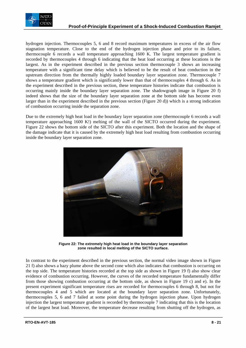
Due to the extremely high heat load in the boundary layer separation zone (thermocouple 6 records a wall temperature approaching 1600 K!) melting of the wall of the SICTO occurred during the experiment. Figure 22 shows the bottom side of the SICTO after this experiment. Both the location and the shape of the damage indicate that it is caused by the extremely high heat load resulting from combustion occurring inside the boundary layer separation zone.
Figure 22: The extremely high heat load in the boundary layer separation zone resulted in local melting of the SICTO surface.
In contrast to the experiment described in the previous section, the normal video image shown in Figure 21 f) also shows a hazy plume above the second cone which also indicates that combustion is occurring on the top side. The temperature histories recorded at the top side as shown in Figure 19 f) also show clear evidence of combustion occurring. However, the curves of the recorded temperature fundamentally differ from those showing combustion occurring at the bottom side, as shown in Figure 19 c) and e). In the present experiment significant temperature rises are recorded for thermocouples 6 through 8, but not for thermocouples 4 and 5 which are located at the boundary layer separation zone. Unfortunately, thermocouples 5, 6 and 7 failed at some point during the hydrogen injection phase. Upon hydrogen injection the largest temperature gradient is recorded by thermocouple 7 indicating that this is the location of the largest heat load. Moreover, the temperature decrease resulting from shutting off the hydrogen, as
Proof-of-Principle Experiment of a Shock-Induced Combustion Ramjet
8 - 22 RTO-EN-AVT-185
recorded by thermocouple 8, is approximately 150 K, which is significantly larger than the other temperature decreases recorded at this location upon hydrogen shut-off. The above results suggest that a relatively large amount of hydrogen is burned, but apparently not inside the boundary layer separation zone. The shadowgraph image during the hydrogen injection shows that the size of the boundary layer separation zone is indeed only slightly larger when compared to the situation prior to hydrogen injection (Figure 21 e)) and very similar in size when compared to the situation during hydrogen injection in the experiment described in the previous section (Figure 21 d)), where no combustion at all occurred at the top side. From this, it is concluded that shock-induced combustion of hydrogen occurred in the inviscid flow field on the top side of the test object.
4.0 CONCLUSIONS
From the work presented in this paper the following conclusions may be drawn:
• A shock-induced combustion experiment was designed based on extensive CFD and thermo-mechanical analysis aimed at demonstrating that it is possible to inject a highly reactive fuel into a high enthalpy supersonic air flow without causing premature ignition and subsequently induce combustion of this mixture by a strong oblique shock wave.
• Given the constraints of the TNO Free Jet Test Facility, an axi-symmetric double cone test object made from Inconel 617 was placed in a supersonic high enthalpy air flow. Hydrogen was injected through 6 double wedge ramp injectors located upstream of the second cone. The hydrogen would mix with the air flow over the remaining length of the first cone and would encounter a strong oblique shock wave, generated by the second cone, which would induce the combustion of the hydrogen air mixture. Three different second cone segments allowed variations of the strength of the oblique shock wave while the gas supply system of the TNO Free Jet Test Facility could be varied to allow various Mach numbers, stagnation temperatures and stagnation pressures of the supersonic air flow, as well as the injected hydrogen mass flow rate. The test object was equipped with 14 thermocouples to measure the test object wall temperature and 2 thermocouples to measure the gas temperature downstream of the shock-induced combustion zone.
• After successful qualification of the TNO Free Jet Test Facility to provide a supersonic air flow with stagnation temperatures up to 1450 K, the test object was tested successfully during a full operational free jet experiment using nitrogen injection through the wedges into the supersonic air flow having a stagnation temperature of 1300 K.
• A series of shock-induced combustion experiments was executed using the Mach 3.25 free jet nozzle and the 39º second cone angle segment in which the stagnation temperature of the supersonic air flow and the amount of injected hydrogen was varied. The experimental results obtained at three levels of stagnation temperature while injecting the same hydrogen mass flow rate have been described in detail.
• Thermal expansion of the strut holding the test object introduced a small angle-of-attack of the test object of around 2º. Due to this the experiments revealed two modes of combustion:
• At the bottom side, hydrogen was captured in the boundary layer separation zone which started to burn when the stagnation temperature of the air flow reached such a level that the combination of local static temperature and residence time in the separation zone was favorable for the initiation of combustion. This type of combustion resulted in the boundary layer separation zone to increase in size significantly combined with very high local heat loads.
• At sufficiently high air flow stagnation temperature shock-induced combustion occurred at the top side of the test object in the inviscid flow field. This type of combustion did not affect
Proof-of-Principle Experiment of a Shock-Induced Combustion Ramjet
RTO-EN-AVT-185 8 - 23
the size of the boundary layer separation zone and resulted in a peak heat load to occur downstream of the separation zone.
• The experimental results therefore demonstrate that it is in principle possible to inject a highly reactive fuel into a high enthalpy supersonic air flow and subsequently induce combustion of this mixture by a strong oblique shock wave. The results also show that a small deviation in inclination of the test object with respect to the air flow may result in hydrogen to be captured and subsequently burned in the boundary layer separation zone resulting in extremely high local heat loads.
With this, the feasibility of some of the critical aspects of a shock-induced combustion ramjet have been demonstrated. Presently, CFD analyses of the experiments are ongoing in order to improve the understanding of the experimental results.
This research constitutes an important step forward in maturing the technology for hypersonic propulsion systems and is invaluable to improve the understanding and the assessment of combustion processes of hypersonic propulsion systems for future weapon and space launch systems.
5.0 REFERENCES
[1] Veraar, R.G. and Mayer, A.E.H.J., “High Speed Air Breathing Propulsion Systems Research and Development at TNO,” RTO-AVT Innovative Missile Systems Symposium, Amsterdam, The Netherlands, 15-19 May 2006.
[2] Sislian, J.P., Martens, R.P., Schwartzentruber, T.E., and Parent, B., “Numerical Simulation of a Real Shcramjet Flowfield,” Journal of Propulsion and Power, Vol. 22, No. 5, 2006, pp. 1039-1048.
[3] Veraar, R.G. and Mayer, A.E.H.J., “The Role of the TNO Free Jet Test Facility in Solid Fuel Ramjet Projectile Development,” AIAA-2005-3828, 41st AIAA/ASME/SAE/ASEE Joint Propulsion Conference & Exhibit, Tucson, Arizona, USA, July 2005.
[4] Verreault, J., “Design of a Shock-Induced Combustion Experiment in an Axisymmetric Configuration with Hydrogen Injection,” Master Thesis, Faculty of Mechanical Engineering, Laval University, Quebec, Canada, 2007.
[5] Verreault, J., deChamplain, A., Mayer, A.E.H.J., Veraar, R.G., Stowe, R.A., Farinaccio, R., and Harris, P.G., “Design of a Shock-Induced Combustion Experiment in an Axisymmetric Configuration with Hydrogen Injection,” AIAA-2007-5396, 43rd AIAA/ASME/SAE/ASEE Joint Propulsion Conference and Exhibit, Cincinnati, Ohio, USA , 8-11 July 2007.
[6] FLUENT version 6.2.16, ANSYS Inc. (www.ansys.com), Canonsburg, PA, 2006.
[7] ERCO Worldwide, “Hydrogen WHMIS Controlled Product,” Revision #2 (http://www.ercoworldwide.com/documents/ hydrogen.pdf), August 16 2006.
[8] COMSOL Multiphysics version 3.4, COMSOL AB, Stockholm (www.comsol.com), Sweden, 2007.
[9] Settles, G.S., “Schlieren and Shadowgraph Techniques Visualizing Phenomena in Transport Media,” Springer, New York, 2001.

Proof-of-Principle Experiment of a Shock-Induced Combustion Ramjet
8 - 24 RTO-EN-AVT-185