
PROMISE DI1 6c Evaluation of PROMISE Standards - … · ELECTRONIC FILE CODE promise di1 6c...
31
Copyright © PROMISE Consortium 2004-2008 DELIVERABLE NO DI1.6c: Evaluation of PROMISE standards DISSEMINATION LEVEL PUBLIC DATE 14. April 2008 WORK PACKAGE NO WP I1: Standardisation VERSION NO. 0.1 ELECTRONIC FILE CODE promise di1 6c evaluation of promise standards.doc CONTRACT NO 507100 PROMISE A Project of the 6th Framework Programme Information Society Technologies (IST) ABSTRACT This report is the third of a three-part series of deliverables aimed to document the activities on evaluation and refinement of PROMISE standards and architecture specifications. In this report, a roadmap for the standardisation and refinement of the PDKM SOM, which will be followed by PROMISE Innovations, is given. The report also describes the progress and the documentation of PMI from M36-M42. STATUS OF DELIVERABLE ACTION BY DATE (dd.mm.yyyy) SUBMITTED (author(s)) Damith C. Ranasinghe 30.04.2008 VU (WP Leader) Ajith Parlikad 30.04.2008 APPROVED (QIM) Dimitris Kiritsis 02.05.2008 Damith C. Ranasinghe, Cambridge Robertino Solanas, BIBA Jacopo Cassina, POLIMI David Potter, INDYON Björn Forss, TRACKWAY Mark Harrison, Cambridge Ajith Parlikad, Cambridge Kary Framling, HUT DI1.6: Evaluation of PROMISE Standards
Transcript of PROMISE DI1 6c Evaluation of PROMISE Standards - … · ELECTRONIC FILE CODE promise di1 6c...
Copyright © PROMISE Consortium 2004-2008
DELIVERABLE NO DI1.6c: Evaluation of PROMISE standards
DISSEMINATION LEVEL PUBLIC
DATE 14. April 2008
WORK PACKAGE NO WP I1: Standardisation
VERSION NO. 0.1
ELECTRONIC FILE CODE promise di1 6c evaluation of promise standards.doc
CONTRACT NO 507100 PROMISE A Project of the 6th Framework Programme Information Society Technologies (IST)
ABSTRACT This report is the third of a three-part series of deliverables aimed to document the activities on evaluation and refinement of PROMISE standards and architecture specifications. In this report, a roadmap for the standardisation and refinement of the PDKM SOM, which will be followed by PROMISE Innovations, is given. The report also describes the progress and the documentation of PMI from M36-M42.
STATUS OF DELIVERABLE
ACTION BY DATE (dd.mm.yyyy)
SUBMITTED (author(s)) Damith C. Ranasinghe 30.04.2008
VU (WP Leader) Ajith Parlikad 30.04.2008
APPROVED (QIM) Dimitris Kiritsis 02.05.2008
Written by:
Damith C. Ranasinghe, Cambridge
Robertino Solanas, BIBA Jacopo Cassina, POLIMI
David Potter, INDYON Björn Forss, TRACKWAY Mark Harrison, Cambridge Ajith Parlikad, Cambridge
Kary Framling, HUT
DI1.6: Evaluation of PROMISE Standards
Copyright © PROMISE Consortium 2004-2008 Page ii
@
Revision History Date
(dd.mm.yyyy) Version Author Comments
02.03.2008 0.1 Damith Draft outline 0.2 Ajith Draft outline edit 0.3 Robertino Open source PDKM SOM 0.4 David Edit draft 0.5 Bjorn PMI developments 0.6 Jacopo and Damith PDKM roadmap 0.7 D. Ranasinghe Edit and merge changes 0.8 Jacopo and Robertino Edit PDKM roadmap & MDA implementation details
12.05.2008 0.9 Ajith and Damith Edit – sent for review 0.9 Mark and Jacopo Changes incorporated by Damith
14.05.2008 1.0 Damith Final version
Author(s)’ contact information
Name Organisation E-mail Tel Fax Damith Ranasinghe Cambridge University [email protected] Robertino Solanas BIBA [email protected] Jacopo Cassini POLIMI [email protected] 390223993951 390223992700 David Potter INDYON [email protected] 442392345152 442392592327 Björn Forss Trackway [email protected] Mark Harrison Cambridge University [email protected] Ajith Parlikad Cambridge University aknp2 @cam.ac.uk 441223765606 Kary Framling HUT
Copyright © PROMISE Consortium 2004-2008 Page 3
@
Table of Contents 1 INTRODUCTION................................................................................................................................................5 2 DOCUMENTATION OF THE PROMISE ARCHITECTURE ......................................................................5 3 DEVELOPMENT AND STANDARDIZATION OF THE PDKM SOM .......................................................7
3.1 PDKM IMPROVEMENTS ................................................................................................................................9 3.2 THE ONTOLOGY ............................................................................................................................................9 3.3 PDKM SOM VALIDATION THROUGH IMPLEMENTATION.............................................................................14
3.3.1 Building blocks of the PDKM´s static application level ........................................................................15 3.3.2 Web Service-Layer.................................................................................................................................16 3.3.3 PMI-Layer..............................................................................................................................................16 3.3.4 Application-Layer ..................................................................................................................................16 3.3.5 Persistence-Layer ..................................................................................................................................16 3.3.6 Standardized way to develop an application specific model based on SOM via MDA..........................17 3.3.7 Short Introduction to the Model-driven-architecture approach ............................................................18 3.3.8 MDA generated artefacts and their programmatic use .........................................................................20 3.3.9 Summary ................................................................................................................................................21
3.4 STANDARDISING THE PDKM SOM .............................................................................................................22 4 DEVELOPMENTS IN THE PMI SPECIFICATION ....................................................................................23 5 CONCLUSIONS ................................................................................................................................................25 6 ANNEX 1: THE EXPRESS PDKM MODEL..................................................................................................26
6.1 INTRODUCTION TO THE EXPRESS LANGUAGE ...........................................................................................26 6.2 EXPRESS MODEL OF THE PDKM ..............................................................................................................26
List of figures FIGURE 1: PROMISE CONNECTIVITY. .............................................................................................................................5 FIGURE 2: PDKM ROADMAP............................................................................................................................................8 FIGURE 3: STRUCTURE OF THE PDKM ONTOLOGY ........................................................................................................10 FIGURE 4: THE PDKM ONTOLOGY CLASS VIEW ............................................................................................................11 FIGURE 5: PDKM ONTOLOGY ATTRIBUTES VIEW ..........................................................................................................11 FIGURE 6: INSTANTIATION OF THE PDKM ONTOLOGY – A MILLING MACHINE K211....................................................12 FIGURE 7: MILLING MACHINE MOL PHASE ....................................................................................................................12 FIGURE 8: PDKM-LAYER-MODEL .................................................................................................................................15 FIGURE 9: FOUR-LAYER METAMODELING ARCHITECTURE OF THE MDA APPROACH BASED ON [GDD06]......................18 FIGURE 10: GENERATION STEPS: FROM M1 TO M0.........................................................................................................19 FIGURE 11: GENERATED HIBERNATE-MAPPING ARTEFACT FOR THE SOM´S DEFINED ENTITY PHYSICAL PRODUCT. ......20 FIGURE 12: FIGURE 5: HIBERNATE-MAPPING ARTEFACT FOR ENTITY ENGINE (A2) AS AN EXTENSION OF SOM´S PHYSICAL
PRODUCT DEFINITION............................................................................................................................................21 FIGURE 13: PROGRAMMATIC USE OF AN APPLICATION SPECIFIC MODEL (A2).................................................................21
Copyright © PROMISE Consortium 2004-2008 Page 4
@
Abbreviations DBMS: Data Base Management System DSS: Decision Support System DC: Device Controller ERP: Enterprise Resource Planning MDA: Model Driven Architecture OMG: Object Management Group PEID: Product Embedded Information Device PMI: PROMISE Middleware Interface PDKM: Product Data Knowledge Management PLCS: Product Life Cycle Support PIM: Platform independent model PSM: Platform specific model PLM: Product Lifecycle Management PDM: Platform definition model PDM: Product Data Management SOM: Semantic Object Model UML: Unified Modelling Language XMI: XML Metadata Interchange XML: eXtensible Markup Language
Copyright © PROMISE Consortium 2004-2008 Page 5
@
1 Introduction
The overall goal for PROMISE work package I1 is to ensure that there is an open channel for the continuing promotion and acceptance of key elements of the PROMISE architecture into standards (or set of standards) and interfaces defined during the PROMISE project.
This report is the final of a three-part series of deliverables aimed to document the activities on evaluation and refinement of PROMISE standards and architecture specifications. This deliverable describes the development of the PROMISE architecture components that are being promoted as new standards: PDKM SOM as a PLM data representation standard and the PMI as a PLM data exchange standard.
This deliverable presents the following:
Outline of the documentation of the PROMISE architecture at M42
Standardisation roadmap for PDKM SOM and suggested refinements for the SOM.
An open source development of the PROMISE architecture: implementation of the PROMISE PDKM SOM
Progress and the interim documentation of the PMI specification
Activities related to the promotion of PROMISE specifications to standards bodies shall be addressed in DI1.7c.
2 Documentation of the PROMISE architecture
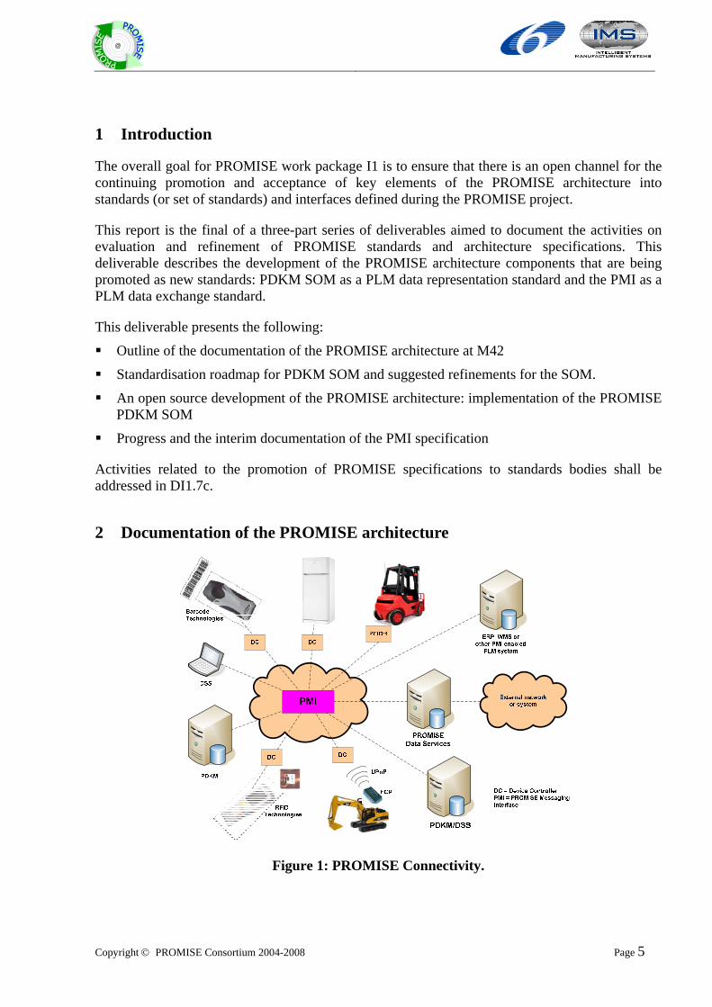
Figure 1: PROMISE Connectivity.
Copyright © PROMISE Consortium 2004-2008 Page 6
@
Figure 1 gives a conceptual impression of the variety of systems, technologies and products that can participate in PROMISE, and, using PROMISE architecture, interfaces and technologies, can exchange product life cycle data, thus closing the life cycle information loop.
These different information systems can be grouped together under the concept of a “node”, whose internal implementation is not critical so long as it is capable of communicating using the PROMISE Messaging Interface (PMI).
The PMI is a key interface which enables a web-services based approach, permitting any PMI-enabled user to exchange data with another. Depending on the complexity of any specific application, this can be achieved on a simple peer-to-peer basis if the two users are known to each other, or on a more complex wide-area basis using advanced PROMISE Data Services (middleware).
The PROMISE connectivity model is similar to that of the World Wide Web (WWW). Where the WWW uses the HTTP protocol for transmitting HTML-coded information mainly intended for human users, PROMISE uses PROMISE Messaging Interface (PMI) for transmitting XML-coded information mainly intended for automatic processing by information systems. It is important to understand these relationships because PROMISE in effect proposes an extension to the WWW itself.
The PROMISE architecture, its relevant interfaces and concepts are described in detail in the reference documentation entitled the PROMISE Architecture Series. While this is not a formal deliverable it is a significant achievement by the consortium to formulate an authoritative source of reference and documentation of the PROMISE information architecture. The documentation of the architecture is organised as described below.
o Volume 1: Architecture Overview: Describes the overall PROMISE information architecture, defines concepts and describes facilities of the architecture. It also describes the components of the PROMISE Architecture, their relationships and options for use, and it is intended to be used in combination with the other volumes in the series which are listed below.
o Volume 2: Architecture Reference: Provides an interface specification of the PROMISE Core PAC Interface.
o Volume 3: Architecture Reference: Provides a reference for the PROMISE Messaging Interface (PMI) and Data Services Concepts with complete descriptions of the methods and associated data structures.
o Volume 4: Architecture Reference: Provides the PROMISE PDKM System Object Model and interfaces.
o Volume 5: Architecture Reference: Provides complete descriptions of the data analysis functions provided by the PROMISE Decision Support Systems (DSSs)
Initially it had been anticipated that the following developer’s guides could also be created before the end of the formal PROMISE project. These volumes will eventually be a significant contribution to the acceptance of PROMISE architecture and standards, therefore their final production will be coordinated by Promise Innovation.
o Volume 6: Developer’s Guide: Descriptive guide to developing the hierarchy of PROMISE Product Embedded Information Devices (PEIDs).
Copyright © PROMISE Consortium 2004-2008 Page 7
@
o Volume 7: Developer’s Guide: Descriptive guide to developing PROMISE Data Services
o Volume 8: Developer’s Guide: Descriptive guide to implementing the PROMISE Product Data and Knowledge Management (PDKM) SOM.
o Volume 9: Developer’s Guide: Descriptive guide to developing and implementing PROMISE Decision Support System (DSS)
3 Development and Standardization of the PDKM SOM
The PROMISE PDKM object model has been developed in the context of WPR9, task TR9.2. It is the conceptual semantic data model behind the PROMISE PDKM system, and in particular it describes the core of the Data Management layer of this system, whose main task is to provide a global semantic view on product and product life cycle data for all analysis applications. Refer to DR9.1, DR9.2 and PROMISE Architecture Series Volumes for a thorough description of the different components that constitute the PROMISE PDKM system architecture.
The current activity for standardization aims at further developing the concepts behind the PROMISE project to be promoted through standardization bodies (refer to deliverable series DI1.7).
PDKM allows the description and management of the data and knowledge of product ITEMS in their physical life; to cover the design phase, where the physical product is still non-existing, it has a specific class that works as a link toward the design standards (or the “product type standards”, such as PLM@XML or some parts of STEP). It has been implemented and tested in 10 applications (MTS has only a theoretical test), and this, connected to the standardization lacking in this field as discussed in deliverable DI1.4, offered the opportunity to present it as a basis for a standard in product data representation.
The PDKM SOM still requires further developments and improvements to achieve this ambitious objective. For this reason, a revision of the existing PDKM SOM is required to take into account the new global architecture that PROMISE has evolved to. This will necessitate the revision of the requirements for the PDKM. Moreover, its structure has to be discussed within a community to create not only a proposal, but also a group which will develop, maintain, support and disseminate it.
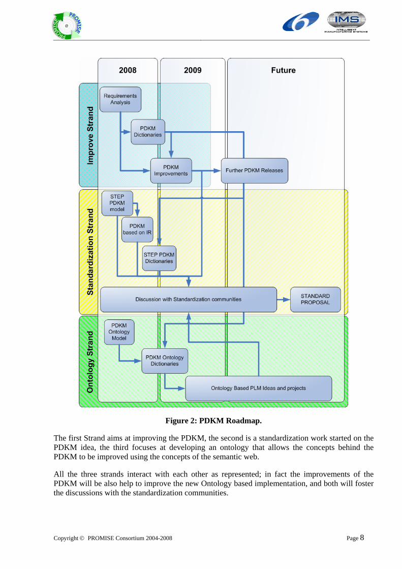
The following presents all ongoing PDKM development activities consisting of three threads, as shown in Figure 2.
Copyright © PROMISE Consortium 2004-2008 Page 8
@
Figure 2: PDKM Roadmap.
The first Strand aims at improving the PDKM, the second is a standardization work started on the PDKM idea, the third focuses at developing an ontology that allows the concepts behind the PDKM to be improved using the concepts of the semantic web.
All the three strands interact with each other as represented; in fact the improvements of the PDKM will be also help to improve the new Ontology based implementation, and both will foster the discussions with the standardization communities.
Copyright © PROMISE Consortium 2004-2008 Page 9
@
These three strands will be discussed in following subsections.
3.1 PDKM Improvements
This thread focuses at improving the PDKM SOM using the new information coming from other sources and the ideas from the new PROMISE architecture. This architecture (Figure 1) is in fact peer-to-peer, and this allows new scenarios, which have to be examined to find possible gaps in the SOM. For this reason a set of new possible scenarios has been designed and is under discussion with the most interested application scenarios.
Another issue to be improved, connected with the standardization work is the creation of “dictionaries” to specify a generic SOM for different application sectors. In fact until now the SOM has generic labels and datatypes. These have to be specified for each application. This is a very good approach for a model that aims at creating a software tool as it was in the initial aims of the PDKM. In fact to create an implementation of the model, the SOM is needed; then the datatypes and the labels can be specified, creating a customized model that fits all the requirements of the specific test case.
However, if two manufacturers of the same sector implement the SOM, they will probably have some differences within the data types and the labels. These can be even very small differences, e.g. the aging value expressed as a number from 1 to 100 or from 0.01 to 1, or the date expressed like a date or like a number, but will hamper the interoperability of the two systems and the data sharing. For this reason, in order to move towards standardisation, the model has to be specified to the maximum level of details possible for the possible sectors of applicability. To begin, the automotive, the milling machine and the white goods sectors have been chosen.
This activity is ongoing in cooperation with BIBA, who have provided the technical competences to define what was needed, and EPFL, who are working on other possible scenarios, Norman Swindells, a STEP expert has offered help for these activities, and regularly provides suggestions on how to improve the model towards standardisation.
The results of this improvements activity will be used both to foster the standardization strand and to be a basis for the new improved versions of the PDKM which will be released by PROMISE-Innovation.
3.2 The Ontology
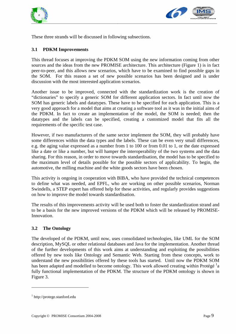
The developed of the PDKM, until now, uses consolidated technologies, like UML for the SOM description, MySQL or other relational databases and Java for the implementation. Another thread of the further developments of this work aims at understanding and exploiting the possibilities offered by new tools like Ontology and Semantic Web. Starting from these concepts, work to understand the new possibilities offered by these tools has started. Until now the PDKM SOM has been adapted and modelled to become ontology. This work allowed creating within Protégé 1a fully functional implementation of the PDKM. The structure of the PDKM ontology is shown in Figure 3.
1 http://protege.stanford.edu
Copyright © PROMISE Consortium 2004-2008 Page 10
@
Figure 3: Structure of the PDKM Ontology
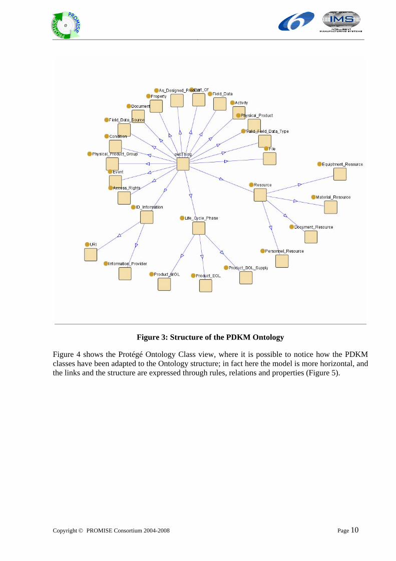
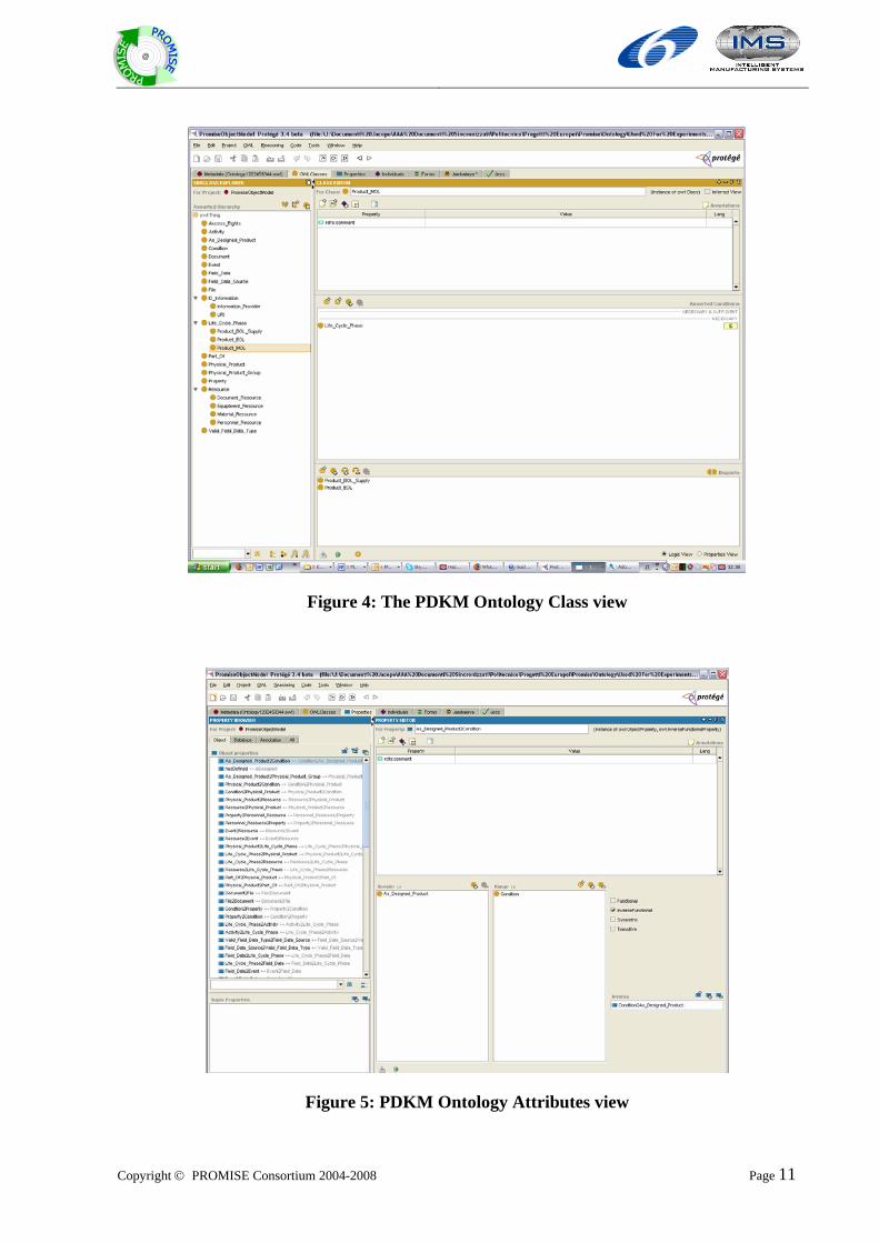
Figure 4 shows the Protégé Ontology Class view, where it is possible to notice how the PDKM classes have been adapted to the Ontology structure; in fact here the model is more horizontal, and the links and the structure are expressed through rules, relations and properties (Figure 5).
Copyright © PROMISE Consortium 2004-2008 Page 11
@
Figure 4: The PDKM Ontology Class view
Figure 5: PDKM Ontology Attributes view
Copyright © PROMISE Consortium 2004-2008 Page 12
@
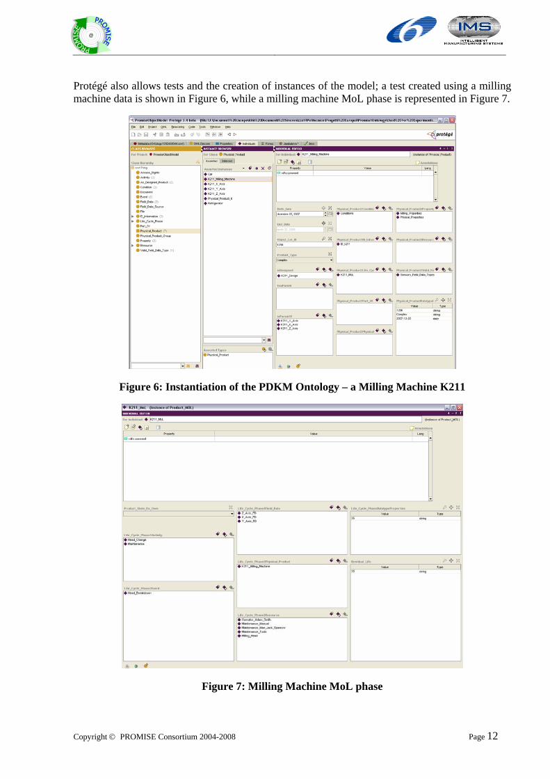
Protégé also allows tests and the creation of instances of the model; a test created using a milling machine data is shown in Figure 6, while a milling machine MoL phase is represented in Figure 7.
Figure 6: Instantiation of the PDKM Ontology – a Milling Machine K211
Figure 7: Milling Machine MoL phase
Copyright © PROMISE Consortium 2004-2008 Page 13
@
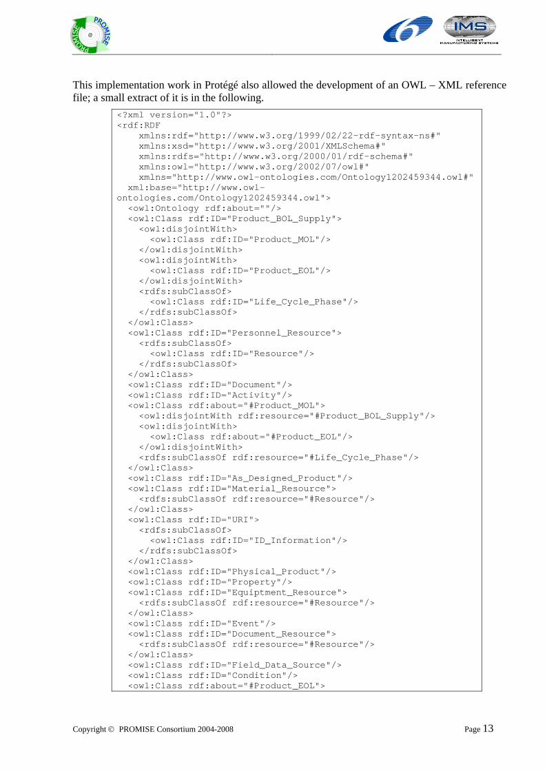
This implementation work in Protégé also allowed the development of an OWL – XML reference file; a small extract of it is in the following.
<?xml version="1.0"?> <rdf:RDF xmlns:rdf="http://www.w3.org/1999/02/22-rdf-syntax-ns#" xmlns:xsd="http://www.w3.org/2001/XMLSchema#" xmlns:rdfs="http://www.w3.org/2000/01/rdf-schema#" xmlns:owl="http://www.w3.org/2002/07/owl#" xmlns="http://www.owl-ontologies.com/Ontology1202459344.owl#" xml:base="http://www.owl-ontologies.com/Ontology1202459344.owl"> <owl:Ontology rdf:about=""/> <owl:Class rdf:ID="Product_BOL_Supply"> <owl:disjointWith> <owl:Class rdf:ID="Product_MOL"/> </owl:disjointWith> <owl:disjointWith> <owl:Class rdf:ID="Product_EOL"/> </owl:disjointWith> <rdfs:subClassOf> <owl:Class rdf:ID="Life_Cycle_Phase"/> </rdfs:subClassOf> </owl:Class> <owl:Class rdf:ID="Personnel_Resource"> <rdfs:subClassOf> <owl:Class rdf:ID="Resource"/> </rdfs:subClassOf> </owl:Class> <owl:Class rdf:ID="Document"/> <owl:Class rdf:ID="Activity"/> <owl:Class rdf:about="#Product_MOL"> <owl:disjointWith rdf:resource="#Product_BOL_Supply"/> <owl:disjointWith> <owl:Class rdf:about="#Product_EOL"/> </owl:disjointWith> <rdfs:subClassOf rdf:resource="#Life_Cycle_Phase"/> </owl:Class> <owl:Class rdf:ID="As_Designed_Product"/> <owl:Class rdf:ID="Material_Resource"> <rdfs:subClassOf rdf:resource="#Resource"/> </owl:Class> <owl:Class rdf:ID="URI"> <rdfs:subClassOf> <owl:Class rdf:ID="ID_Information"/> </rdfs:subClassOf> </owl:Class> <owl:Class rdf:ID="Physical_Product"/> <owl:Class rdf:ID="Property"/> <owl:Class rdf:ID="Equiptment_Resource"> <rdfs:subClassOf rdf:resource="#Resource"/> </owl:Class> <owl:Class rdf:ID="Event"/> <owl:Class rdf:ID="Document_Resource"> <rdfs:subClassOf rdf:resource="#Resource"/> </owl:Class> <owl:Class rdf:ID="Field_Data_Source"/> <owl:Class rdf:ID="Condition"/> <owl:Class rdf:about="#Product_EOL">
Copyright © PROMISE Consortium 2004-2008 Page 14
@
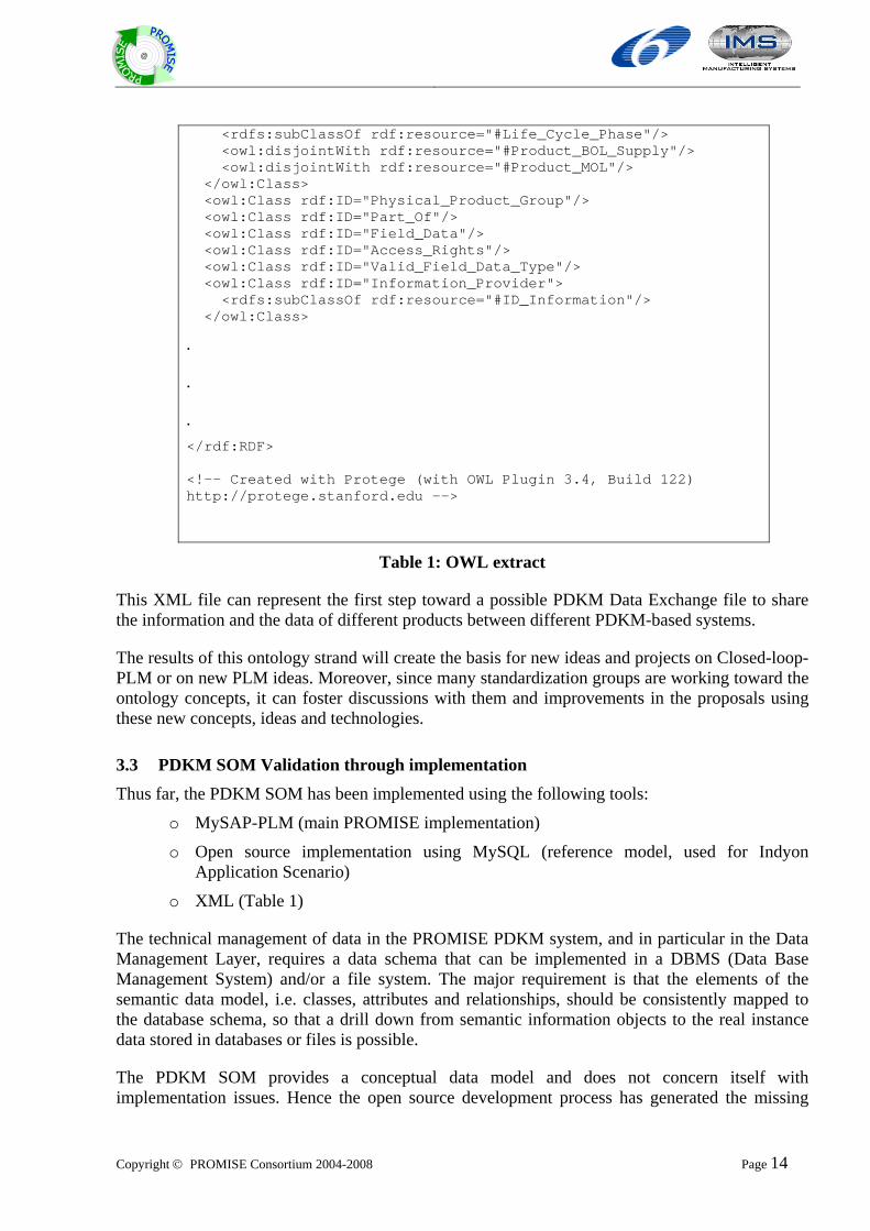
<rdfs:subClassOf rdf:resource="#Life_Cycle_Phase"/> <owl:disjointWith rdf:resource="#Product_BOL_Supply"/> <owl:disjointWith rdf:resource="#Product_MOL"/> </owl:Class> <owl:Class rdf:ID="Physical_Product_Group"/> <owl:Class rdf:ID="Part_Of"/> <owl:Class rdf:ID="Field_Data"/> <owl:Class rdf:ID="Access_Rights"/> <owl:Class rdf:ID="Valid_Field_Data_Type"/> <owl:Class rdf:ID="Information_Provider"> <rdfs:subClassOf rdf:resource="#ID_Information"/> </owl:Class>
.
.
. </rdf:RDF> <!-- Created with Protege (with OWL Plugin 3.4, Build 122) http://protege.stanford.edu -->
Table 1: OWL extract
This XML file can represent the first step toward a possible PDKM Data Exchange file to share the information and the data of different products between different PDKM-based systems.
The results of this ontology strand will create the basis for new ideas and projects on Closed-loop-PLM or on new PLM ideas. Moreover, since many standardization groups are working toward the ontology concepts, it can foster discussions with them and improvements in the proposals using these new concepts, ideas and technologies.
3.3 PDKM SOM Validation through implementation Thus far, the PDKM SOM has been implemented using the following tools:
o MySAP-PLM (main PROMISE implementation)
o Open source implementation using MySQL (reference model, used for Indyon Application Scenario)
o XML (Table 1)
The technical management of data in the PROMISE PDKM system, and in particular in the Data Management Layer, requires a data schema that can be implemented in a DBMS (Data Base Management System) and/or a file system. The major requirement is that the elements of the semantic data model, i.e. classes, attributes and relationships, should be consistently mapped to the database schema, so that a drill down from semantic information objects to the real instance data stored in databases or files is possible.
The PDKM SOM provides a conceptual data model and does not concern itself with implementation issues. Hence the open source development process has generated the missing
Copyright © PROMISE Consortium 2004-2008 Page 15
@
implementation details that are vital for exploiting one of the many project results (the semantic data model) in a more easily reusable implementation solution, covering the needs of both academic/research and industrial partners. This has also served to put to rest any questions regarding implementation of the SOM from a standards document to a practical realisation.
The purpose of the this section is to showcase a methodology to develop the needed building blocks of the PDKM´s static application level as a validation of the PDKM SOM model through an open implementation process. The set of all distributed data and their transparent access and management represents the PDKM. We regard the implementation of a PD(K)M here under exclusion of a knowledge component, therefore the knowledge components such as the data analysis functionalities are excluded here. Concerning the data we will handle inside the PD(K)M we distinguish between static and dynamic data whereby our focus is on static data in terms of long-living data. The semantic object model (SOM), Java based open source technologies, XML, WebServices and the model driven approach (MDA) forms the basic technologies for developing the open source based PDKM.
The focus of the approach presented is on the use of SOM in combination with the MDA approach to develop a standardized approach to develop application specific scenarios in respect to the needed domain model and its persistence.
The current deliverable is listed as a confidential document as it outlines the implementation of a PDKM SOM from a conceptual level to a practical implementation. This section of the deliverable formulates the Volume 8 of the Architecture Series forming the developer’s guide for the PDKM SOM.
3.3.1 Building blocks of the PDKM´s static application level
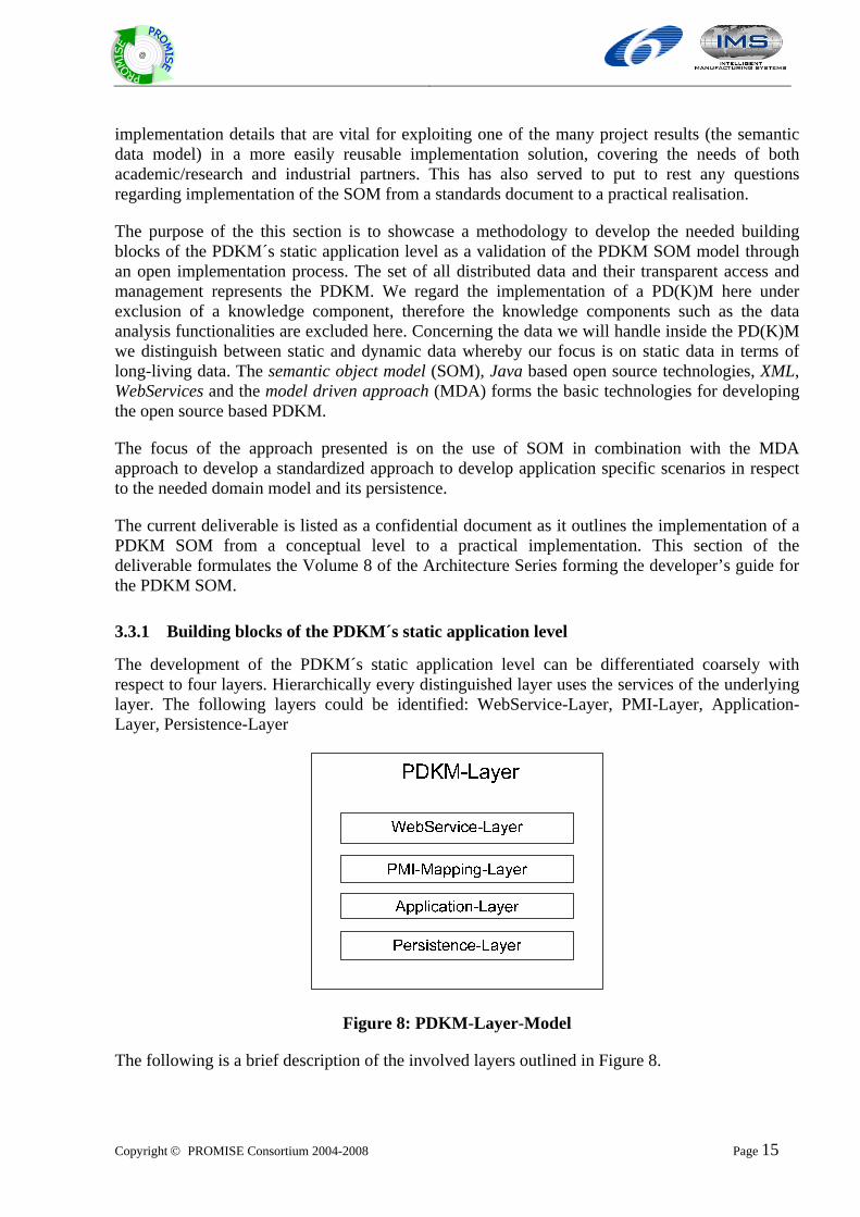
The development of the PDKM´s static application level can be differentiated coarsely with respect to four layers. Hierarchically every distinguished layer uses the services of the underlying layer. The following layers could be identified: WebService-Layer, PMI-Layer, Application-Layer, Persistence-Layer
Figure 8: PDKM-Layer-Model
The following is a brief description of the involved layers outlined in Figure 8.
Copyright © PROMISE Consortium 2004-2008 Page 16
@
3.3.2 Web Service-Layer
The WebService-Layer is used to realize a highly distributed communication level between the PDKM and the involved clients (for example PEID and DSS). It takes the incoming XML based (PMI) messages and passes them to the involved components.
3.3.3 PMI-Layer
The PMI-Mapping-Layer is used to process messages which are conforming to the PMI standard. This layer invokes actions and executes services according to the incoming PMI messages. Examples of the PMI-Mapping-Layer tasks are the following:
Validation of the incoming PMI messages
Evaluation of actions, which must be invoked (update, read etc.)
3.3.4 Application-Layer
The Application-Layer is used to realize all needed components and artefacts for a specific application scenario. Especially the modelling of the generic (SOM) and application specific data model via UML/MDA, the generation of needed artefacts (Java-Objects/Hibernate), development of model-queries and the needed subscription-service are to be mentioned.
3.3.5 Persistence-Layer
The Persistence-Layer is used to create product specific instances with all their attributes and complex product compositions. The main goal of this layer is to handle and support all needed database operations like saving incoming field data and loading them.
The WebService-Layer acts as the main interface to any client and is responsible to take the incoming requests, forward such request to the PMI-Layer and if needed returns accordingly responses as PMI to the appropriate requester. Typically a WSDL for such a WebService-Layer provides methods like “processWriteRequest” and “processReadRequest” which are the main methods to interact with the PDKM. Additionally the WebService-Layer could support methods to execute complex queries like “processQueryRequest” and to cancel Subscriptions via “cancelSubscription”. The development of the WSDL WebService-Layer classes can be done for example by the use of Eclipse IDE for Java EE Developers2. The PMI-Layer will be invoked by the WebService-Layer and is responsible to provide an adequate approach to deal and work with the incoming PMI and to create PMI messages for query results (dataResult). A good way to deal with PMI is to transform it into appropriate OO-classes which are easier to use and provide all benefits of the object orientated approach. A concrete technique for that approach represents JAXB3 which provides the ability to automatically transform XML schema definitions into Java-classes. Such generated classes can than be used directly via JAXB´s supported factories or
2http://www.eclipse.org/downloads/download.php?file=/technology/epp/downloads/release/europa/winter/eclipse-jee-europa-winter-win32.zip
3 Java Access and Binding API for XML - https://jaxb-workshop.dev.java.net/
Copyright © PROMISE Consortium 2004-2008 Page 17
@
beyond that in the form of a “PMI-Builder”4 which is responsible to create PMI messages that can be used for query results but also for any client which needs PMI based read- and write-requests.
The Application-Layer could be logically divided into two phases, a design phase which is used to create all needed artefacts and a runtime phase which is used to process incoming requests and to invoke the Persistence-Layer. The Application-Layer represents the application specific layer inside this suggested PDKM development approach and uses the functionality of the PMI-Layer to interpret incoming requests and to generate appropriate results as PMI messages. The Application-Layer is also responsible for supporting and providing all application specific issues, dependencies and features if necessary. As mentioned above all needed design steps before runtime (which are further below described) which are necessary to develop an application specific domain model based on SOM can be subsumed inside this layer. The Application-Layer acts also in the form of a PDKMService as a facade5 between the incoming PMI requests and the Persistence-Layer and is responsible for invoking the appropriate persistence functionality according to the processed PMI or more complex queries.
The last Layer is called the Persistence-Layer which is responsible for loading and storing all needed data into the chosen database. Hibernate6 which is used by the OS PDKM´s Persistence-Layer is nowadays the first choice inside the Java community to handle relational data via the object orientated approach, fulfils the needs of seamless interactions between objects and relational data and provides all necessary features of modern relational databases like transactions and indexing.
3.3.6 Standardized way to develop an application specific model based on SOM via MDA
In order to be able to use an application specific model programmatically we do need an object orientated layer which represents the model’s inherent defined concepts. To avoid redundant developing and modelling tasks an automatic way of generating all needed artefacts (objects, configurations) based on the SOM model will be introduced here. The goal is to use SOM as a basis to model application specific models which has its specific needs in respect to the used field-data types and complex product compositions offered as templates. Use of a standardized method (MDA) to create application specific models based on SOM and their automatically generation is the main topic of the current section of this deliverable. Section 3.3.7 describes the use of MDA to fulfil a highly abstract and generic way to use SOM for any concrete scenario.
4 http://en.wikipedia.org/wiki/Builder_pattern 5 http://en.wikipedia.org/wiki/Facade_pattern
6 http://www.hibernate.org/
Copyright © PROMISE Consortium 2004-2008 Page 18
@
3.3.7 Short Introduction to the Model-driven-architecture approach
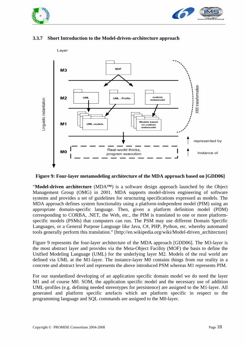
Figure 9: Four-layer metamodeling architecture of the MDA approach based on [GDD06]
“Model-driven architecture (MDA™) is a software design approach launched by the Object Management Group (OMG) in 2001. MDA supports model-driven engineering of software systems and provides a set of guidelines for structuring specifications expressed as models. The MDA approach defines system functionality using a platform-independent model (PIM) using an appropriate domain-specific language. Then, given a platform definition model (PDM) corresponding to CORBA, .NET, the Web, etc., the PIM is translated to one or more platform-specific models (PSMs) that computers can run. The PSM may use different Domain Specific Languages, or a General Purpose Language like Java, C#, PHP, Python, etc. whereby automated tools generally perform this translation.” [http://en.wikipedia.org/wiki/Model-driven_architecture]
Figure 9 represents the four-layer architecture of the MDA approach [GDD06]. The M3-layer is the most abstract layer and provides via the Meta-Object Facility (MOF) the basis to define the Unified Modeling Language (UML) for the underlying layer M2. Models of the real world are defined via UML at the M1-layer. The instance-layer M0 contains things from our reality in a concrete and abstract level and represents the above introduced PSM whereas M1 represents PIM.
For our standardized developing of an application specific domain model we do need the layer M1 and of course M0. SOM, the application specific model and the necessary use of addition UML-profiles (e.g. defining needed stereotypes for persistence) are assigned to the M1-layer. All generated and platform specific artefacts which are platform specific in respect to the programming language and SQL commands are assigned to the M0-layer.
Copyright © PROMISE Consortium 2004-2008 Page 19
@
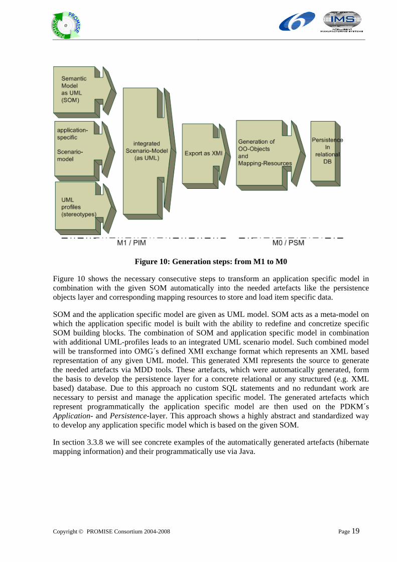
Figure 10: Generation steps: from M1 to M0
Figure 10 shows the necessary consecutive steps to transform an application specific model in combination with the given SOM automatically into the needed artefacts like the persistence objects layer and corresponding mapping resources to store and load item specific data.
SOM and the application specific model are given as UML model. SOM acts as a meta-model on which the application specific model is built with the ability to redefine and concretize specific SOM building blocks. The combination of SOM and application specific model in combination with additional UML-profiles leads to an integrated UML scenario model. Such combined model will be transformed into OMG´s defined XMI exchange format which represents an XML based representation of any given UML model. This generated XMI represents the source to generate the needed artefacts via MDD tools. These artefacts, which were automatically generated, form the basis to develop the persistence layer for a concrete relational or any structured (e.g. XML based) database. Due to this approach no custom SQL statements and no redundant work are necessary to persist and manage the application specific model. The generated artefacts which represent programmatically the application specific model are then used on the PDKM´s Application- and Persistence-layer. This approach shows a highly abstract and standardized way to develop any application specific model which is based on the given SOM.
In section 3.3.8 we will see concrete examples of the automatically generated artefacts (hibernate mapping information) and their programmatically use via Java.
Copyright © PROMISE Consortium 2004-2008 Page 20
@
3.3.8 MDA generated artefacts and their programmatic use
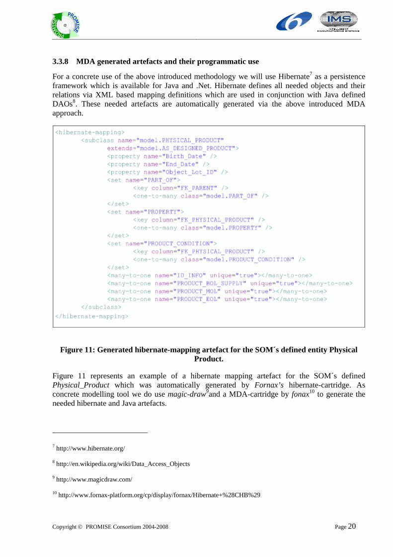
For a concrete use of the above introduced methodology we will use Hibernate7 as a persistence framework which is available for Java and .Net. Hibernate defines all needed objects and their relations via XML based mapping definitions which are used in conjunction with Java defined DAOs8. These needed artefacts are automatically generated via the above introduced MDA approach.
Figure 11: Generated hibernate-mapping artefact for the SOM´s defined entity Physical Product.
Figure 11 represents an example of a hibernate mapping artefact for the SOM´s defined Physical_Product which was automatically generated by Fornax’s hibernate-cartridge. As concrete modelling tool we do use magic-draw9and a MDA-cartridge by fonax10 to generate the needed hibernate and Java artefacts.
7 http://www.hibernate.org/
8 http://en.wikipedia.org/wiki/Data_Access_Objects
9 http://www.magicdraw.com/
10 http://www.fornax-platform.org/cp/display/fornax/Hibernate+%28CHB%29
Copyright © PROMISE Consortium 2004-2008 Page 21
@
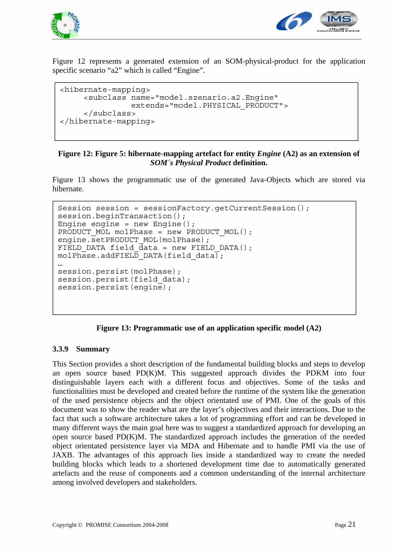
Figure 12 represents a generated extension of an SOM-physical-product for the application specific scenario “a2” which is called “Engine”.
Figure 12: Figure 5: hibernate-mapping artefact for entity Engine (A2) as an extension of SOM´s Physical Product definition.
Figure 13 shows the programmatic use of the generated Java-Objects which are stored via hibernate.
Figure 13: Programmatic use of an application specific model (A2)
3.3.9 Summary
This Section provides a short description of the fundamental building blocks and steps to develop an open source based PD(K)M. This suggested approach divides the PDKM into four distinguishable layers each with a different focus and objectives. Some of the tasks and functionalities must be developed and created before the runtime of the system like the generation of the used persistence objects and the object orientated use of PMI. One of the goals of this document was to show the reader what are the layer’s objectives and their interactions. Due to the fact that such a software architecture takes a lot of programming effort and can be developed in many different ways the main goal here was to suggest a standardized approach for developing an open source based PD(K)M. The standardized approach includes the generation of the needed object orientated persistence layer via MDA and Hibernate and to handle PMI via the use of JAXB. The advantages of this approach lies inside a standardized way to create the needed building blocks which leads to a shortened development time due to automatically generated artefacts and the reuse of components and a common understanding of the internal architecture among involved developers and stakeholders.
<hibernate-mapping> <subclass name="model.szenario.a2.Engine"
extends="model.PHYSICAL_PRODUCT"> </subclass> </hibernate-mapping>
Session session = sessionFactory.getCurrentSession(); session.beginTransaction(); Engine engine = new Engine(); PRODUCT_MOL molPhase = new PRODUCT_MOL(); engine.setPRODUCT_MOL(molPhase); FIELD_DATA field_data = new FIELD_DATA(); molPhase.addFIELD_DATA(field_data); … session.persist(molPhase); session.persist(field_data); session.persist(engine);
Copyright © PROMISE Consortium 2004-2008 Page 22
@
One shortcoming of this approach is the fact that complex queries can not be handled straight forward using PMI as the only accepted interchange format. To fulfil such complex requests the PDKM must provide the ability to support interfaces which are responsible for handling complex queries beside the PMI interface.
3.4 Standardising the PDKM SOM Standardization of PDKM SOM is a complex process, and discussions regarding this have been initiated with some of the major standardization groups and bodies. A summary of these activities can be obtained from the deliverable series DI1.7.
However as mentioned in previous sections, additional work is required to propose the PDKM as a basis for standardization. The PDKM SOM structure is flexible and scalable but discussions with Norman Swindells and BIBA have revealed that we need to specify the SOM within different application sectors (e.g. Automotive, EOL for plastic, etc.). This process should be done with content specific dictionaries, similar to the STEP standard11) or the EPCglobal’s EPCIS standard12. This work has currently started and it will take the application scenarios of PROMISE into “sectors” (e.g. “automotive” will include both CRF applications and CAT) to develop some first dictionaries based on those demonstrator scenarios. This will serve as a starting point in the roadmap to better understand the possibilities in this novel direction of developing a standard for promotion for closed loop PLM.
One of the most promising groups to work with is the STEP community; in fact PDKM has already strong links to STEP since it was considered during its development, so most of the SOM classes are similar to STEP Integrated Resources. Using the common features between STEP’s Integrate Resources (IRs) and PDKM SOM classes, it is feasible to start working together with the STEP community to use the PDKM SOM as the foundation for an Application Protocol (AP). An AP is basically a data model for a specific industrial domain.
To foster the discussion with the STEP community, which is one of the most promising for the promotion of the PDKM as a basis of a standard, the SOM has been adapted and re-written in EXPRESS, which is the data modelling language of STEP. A draft version of this is presented in the appendix.
The PDKM EXPRESS model will also be improved in the future using the Dictionaries that are under development. The PDKM model will also be represented using the IR building blocks; this work has already started and a first mapping has been done (Error! Reference source not found.).
11 http://www.steptools.com/library/standard/
12 http://www.epcglobalinc.org/standards/
Copyright © PROMISE Consortium 2004-2008 Page 23
@
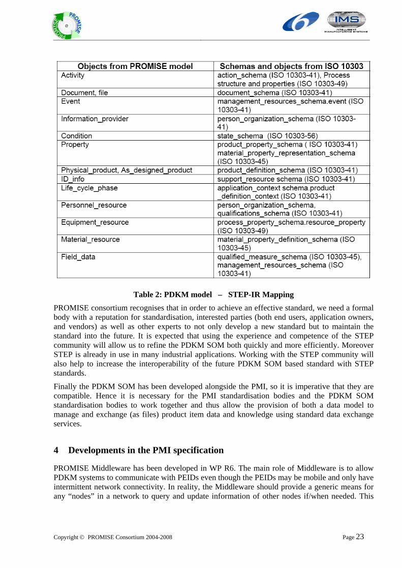
Table 2: PDKM model – STEP-IR Mapping PROMISE consortium recognises that in order to achieve an effective standard, we need a formal body with a reputation for standardisation, interested parties (both end users, application owners, and vendors) as well as other experts to not only develop a new standard but to maintain the standard into the future. It is expected that using the experience and competence of the STEP community will allow us to refine the PDKM SOM both quickly and more efficiently. Moreover STEP is already in use in many industrial applications. Working with the STEP community will also help to increase the interoperability of the future PDKM SOM based standard with STEP standards.
Finally the PDKM SOM has been developed alongside the PMI, so it is imperative that they are compatible. Hence it is necessary for the PMI standardisation bodies and the PDKM SOM standardisation bodies to work together and thus allow the provision of both a data model to manage and exchange (as files) product item data and knowledge using standard data exchange services.
4 Developments in the PMI specification
PROMISE Middleware has been developed in WP R6. The main role of Middleware is to allow PDKM systems to communicate with PEIDs even though the PEIDs may be mobile and only have intermittent network connectivity. In reality, the Middleware should provide a generic means for any “nodes” in a network to query and update information of other nodes if/when needed. This
Copyright © PROMISE Consortium 2004-2008 Page 24
@
means that it should also be possible to implement e.g. PDKM-to-PDKM and PEID-to-PEID communication using the Middleware.
The Promise Middleware Interface (PMI) has been specified in PROMISE Architecture Series Volume 3. The PMI defines an XML format for communication of data required for implementation of a PROMISE Middleware and the communication between the PROMISE Middleware and systems like the PDKM and DSS. PMI is based on XML message exchange, using a Web Service interface or plain HTTP POST communication.
The main development between PMI v2.0 (documented in PROMISE deliverable DR6.5) and PMI v3.0 are summarised here (for details on each of the following points, see Architecture Series Volume 3).
Migration from a multi function Web Service communication interface to a one function Web Service or HTTP POST communication interface. Removing unnecessary complexity from the interface itself makes the PMI easier to use and adapt to different scenarios. Allowing simple HTTP POST communication allows for devices with limited Web Service capabilities to send and receive PMI messages.
Use of the same interface for call-back messages as for placing requests. The PMI became a bidirectional interface. (Systems are still allowed to only support one direction communication, for example, not all systems can and should support handling of subscription requests.)
Moved from a PEID centric approach to a more generic approach where data is communicated about ‘targets’, which are more general and not limited to UPnP or RFID based PEIDs.
Introduction of function type, content type and subject type definitions to define the content of a PMI message more clearly.
Introduction of generic subscriptions to allow easier subscription management. Subscriptions can be made to messages types (content type or subject type), id ranges, etc. Removed limitations in establishing subscriptions (such as separate subscription required per target) to allow for more generic subscriptions. The subscriptions became a means for a system to tell what type of data it desires, and is not limited to asking for specific, predefined data instances.
Allowed for communication between any nodes connected to a PROMISE middleware to use PMI. PMI is no longer dedicated to the communication from PDKM towards the DC handling the PEID.
Modified metadata content to allow for various properties about targets and infoItems to be communicated.
Introduction of new message types, PLM events, system events, device management events, alarm events.
Made the PMI structure more general, but still specific enough to communicate data in a unambiguous way. Allowed for communication of metadata, PLM event, system management events, device events and alarm events using same interfaces and message structure as for field data. The same base data structure suits all the above event types.
Introduced metadata for message types (PLM events, system events, device management events, alarm events) for targets using same metadata structure as for field events. Targets can have metadata defined for the events they generate, or systems generate metadata about them.
Copyright © PROMISE Consortium 2004-2008 Page 25
@
Clarification of subscription parameters such as time-to-live and subscription interval.
Defined a base set of PLM events common in PLM applications.
Improved and clarified generic requirements and guidelines on how systems should handle subscriptions and requests.
Defined basic PMI based Middleware functionality feature requirements, without defining and limiting implementations. Such functionality as discovery service, device management (keeping track of devices to make sure data messages reach the devices), system management (keeping track of other PMI nodes and their roles in the application), metadata management and storing, routing of messages between PMI nodes. The features are defined on a level of “what service they should provide”, but actual implementation is outside the scope of PMI.
Introduced PMI node information in the PMI schema to direct the PMI messages to predefined nodes where applicable.
General improvements to the PMI XSD schema. Unnecessary complexity and limitations removed.
Introduction of PMI XSD name space.
Capability to extend the PMI XSD schema to allow application specific data structures.
Initial definition of PMI level error messages.
5 Conclusions
This report is the last of a three-part series of deliverables aimed to document the activities on evaluation and refinement of PROMISE standards and architecture specifications. In this report, we have provided a summary of the result of activities undertaken during M36-M42 of the PROMISE project.
Throughout its lifetime, the PROMISE project has taken great care to take advantage of existing standards and avoid duplication of standards or creation of competitive standards. As a result of the research and development undertaken during the PROMISE project, two candidates for standards submission have been identified:
1. The PROMISE Messaging Interface, or PMI, and 2. The PROMISE Product Data and Knowledge Management (PDKM) System Object Model
(SOM).
This deliverable has described the developments in the above two aspects of the PROMISE information architecture. We have presented:
The developments in the PMI specification
Developments in the refinement of the PDKM SOM as well as a roadmap for the standardisation of the PDKM SOM
The verification through implementation of the PDKM SOM as part of an open source project.
While this is the final deliverable in a three part series, the development of the PMI and the PDKM SOM will still continue into the future. Further work is expected to be carried out by PROMISE-Innovation’s European Centre of Excellence for Closed-loop Lifecycle Management,
Copyright © PROMISE Consortium 2004-2008 Page 26
@
which is being established to further the results of PROMISE working together with other motivated partners from the project consortium.
6 Annex 1: The EXPRESS PDKM model
6.1 Introduction to the EXPRESS Language
EXPRESS is the data modelling language of STEP and standardized as ISO 10303-11.
An EXPRESS data model can be defined in two ways, textually and graphically. For formal verification and as input for tools such as SDAI the textual representation within an ASCII file is the most important one. The graphical representation on the other hand is often more suitable for human use such as explanation and tutorials. The graphical representation, called EXPRESS-G, is not able to represent all details that can be formulated in the textual form.
EXPRESS is similar to programming languages such as PASCAL. Within a SCHEMA various datatypes can be defined together with structural constraints and algorithmic rules. A main feature of EXPRESS is the possibility to formally validate a population of datatypes - this is to check for all the structural and algorithmic rules.
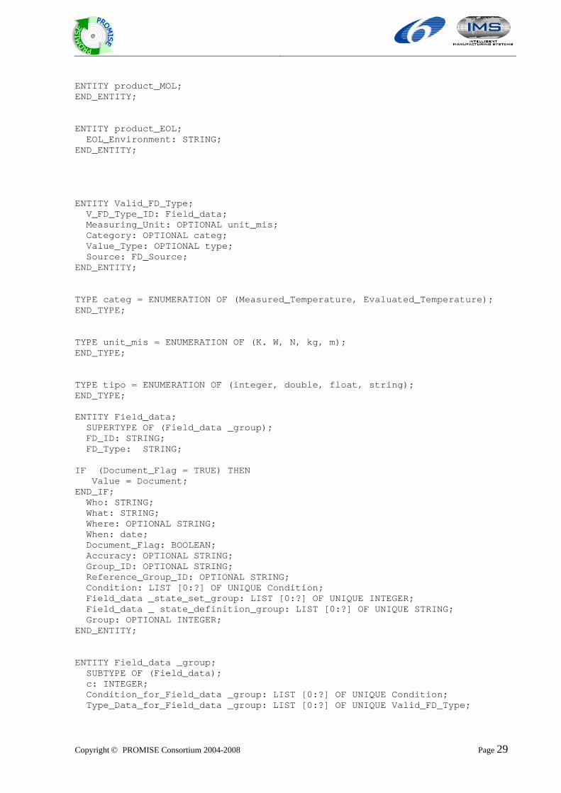
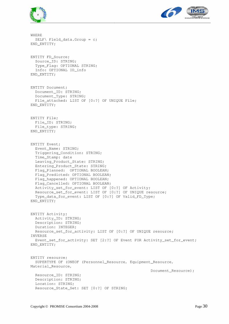
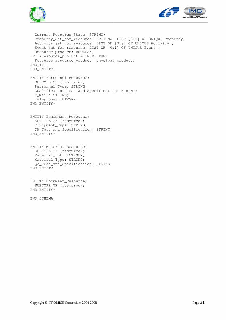
6.2 EXPRESS Model of the PDKM
This the first draft of the EXPRESS model of the PDKM. It still requires checks and verifications and is still under development. SCHEMA semantic_object_model; TYPE date = ARRAY [1:3] OF INTEGER; END_TYPE; ENTITY physical_product; SUPERTYPE OF (Physical_product_group); Product_Type : As_designed_product; Object_Lot_ID : STRING; Birth_Date : date; End_Date: OPTIONAL date; Component: SET [0:?] OF physical_product; From: OPTIONAL date; To: OPTIONAL date; Info: ID_info; Info_life_cycle_phase: Life_Cycle_Phase; Condition_for_product: LIST [0:?] OF UNIQUE Condition; Property_for_product: LIST [0:?] OF UNIQUE Property; Type_Data: LIST [0:?] OF UNIQUE Valid_FD_Type; Product_state_set_group: LIST [0:?] OF UNIQUE INTEGER; Product_state_definition_group: LIST [0:?] OF UNIQUE STRING; Group: OPTIONAL INTEGER; INVERSE Parent : SET [0:1] OF physical_product FOR Component; END_ENTITY;
Copyright © PROMISE Consortium 2004-2008 Page 27
@
ENTITY Physical_product_group SUBTYPE OF (physical_product); a: INTEGER; Condition_for_product_group: LIST [0:?] OF UNIQUE Condition; Type_data_for_ product_group: LIST [0:?] OF UNIQUE Valid_FD_Type WHERE SELF\ physical_product.Group = a; END_ENTITY; ENTITY ID_info; ID: STRING; ID_type: STRING; Alt_Pres: OPTIONAL STRING; info_URI: OPTIONAL LIST [1:?] OF UNIQUE URI; info_ INFORMATION_PROVIDER: OPTIONAL LIST [1:?] OF UNIQUE INFORMATION_PROVIDER; END_ENTITY; ENTITY URI; Uri: STRING; Type: STRING; END_ENTITY; ENTITY INFORMATION_PROVIDER; ID: STRING; ID_type: STRING; Alt_pres: STRING; Type: STRING; END_ENTITY; ENTITY Access_rights; END_ENTITY; ENTITY As_designed_product; SUPERTYPE OF (As_designed_product _group); Product_type_ID: STRING; CAD_Model: SET OF [0:?] OF STRING; BoM: STRING; Materials_Information: SET OF [0:?] OF STRING; Costs_Information: SET OF [0:?] OF STRING; Variants_Information: SET OF [0:?] OF STRING; Tests_and_Specification: SET OF [0:?] OF STRING; Product_State_Set: LIST [0:?] OF UNIQUE INTEGER; Product_State_Definition: LIST [0:?] OF UNIQUE STRING; Property_Set: OPTIONAL LIST [1:?] OF UNIQUE Property; Condition_Set: OPTIONAL LIST OF [1:?] OF UNIQUE Condition; Data: OPTIONAL LIST OF [1:?] OF UNIQUE Valid_FD_Type ; As_designed_product_state_set_group: LIST [0:?] OF UNIQUE INTEGER; As_designed_product_state_definition_group: LIST [0:?] OF UNIQUE STRING; Group: OPTIONAL INTEGER; Source: LIST [0:?] OF UNIQUE FD_Source; END_ENTITY; ENTITY As_designed_product _group; SUBTYPE OF (As_designed_product);
Copyright © PROMISE Consortium 2004-2008 Page 28
@
b: INTEGER; Condition_for_ As_designed_product _group: LIST [0:?] OF UNIQUE Condition; Type_data_for_ As_designed_product_group: LIST [0:?] OF UNIQUE Valid_FD_Type; WHERE SELF\ As_designed_product.Group = b; END_ENTITY; ENTITY Property; Property_name: STRING; Property_Value: STRING; Valid_Values: SET OF [0:?] OF STRING; Category: cat_type; Condition_for_property: OPTIONAL LIST OF [1:?] OF UNIQUE Condition; END_ENTITY; TYPE cat_type = ENUMERATION OF (fixed, arbitrary, conditioning); END_TYPE; ENTITY Condition; Condition_ID: STRING; Group_ID: OPTIONAL STRING IF (Falg_FD/property = TRUE) THEN Type_ID: Property; ELSE IF (Falg_FD/property = FALSE) THEN Type_ID: Field_data; END_IF; END_IF; Condition_Value: SET OF [0:?] OF STRING; Flag_OR/AND: OPTIONAL BOOLEAN; Falg_FD/property: OPTIONAL BOOLEAN; Action_When_Met: OPTIONAL STRING; Action_When_Not_Met: OPTIONAL STRING; END_ENTITY; ENTITY Life_Cycle_Phase; Residual_life: INTEGER; Product_State_Set_Its_Own: OPTIONAL STRING; Product_State_Definition_Its_Own: OPTIONAL STRING; Info_faseBOL: OPTIONAL product_BOL_supply; Info_faseMOL: OPTIONAL product_MOL; Info_faseEOL: OPTIONAL product_EOL; Event_set: LIST OF [0:?] OF Event ; Activity_set: LIST OF [0:?] OF Activity; Resource_set: LIST OF [0:?] OF resource; Type_Data_set: LIST OF [0:?] OF Valid_FD_Type; END_ENTITY; ENTITY product_BOL_supply; supply_Enviroment: STRING; END_ENTITY;
Copyright © PROMISE Consortium 2004-2008 Page 29
@
ENTITY product_MOL; END_ENTITY; ENTITY product_EOL; EOL_Environment: STRING; END_ENTITY; ENTITY Valid_FD_Type; V_FD_Type_ID: Field_data; Measuring_Unit: OPTIONAL unit_mis; Category: OPTIONAL categ; Value_Type: OPTIONAL type; Source: FD_Source; END_ENTITY; TYPE categ = ENUMERATION OF (Measured_Temperature, Evaluated_Temperature); END_TYPE; TYPE unit_mis = ENUMERATION OF (K. W, N, kg, m); END_TYPE; TYPE tipo = ENUMERATION OF (integer, double, float, string); END_TYPE; ENTITY Field_data; SUPERTYPE OF (Field_data _group); FD_ID: STRING; FD_Type: STRING; IF (Document_Flag = TRUE) THEN Value = Document; END_IF; Who: STRING; What: STRING; Where: OPTIONAL STRING; When: date; Document_Flag: BOOLEAN; Accuracy: OPTIONAL STRING; Group_ID: OPTIONAL STRING; Reference_Group_ID: OPTIONAL STRING; Condition: LIST [0:?] OF UNIQUE Condition; Field_data _state_set_group: LIST [0:?] OF UNIQUE INTEGER; Field_data _ state_definition_group: LIST [0:?] OF UNIQUE STRING; Group: OPTIONAL INTEGER; END_ENTITY; ENTITY Field_data _group; SUBTYPE OF (Field_data); c: INTEGER; Condition_for_Field_data _group: LIST [0:?] OF UNIQUE Condition; Type_Data_for_Field_data _group: LIST [0:?] OF UNIQUE Valid_FD_Type;
Copyright © PROMISE Consortium 2004-2008 Page 30
@
WHERE SELF\ Field_data.Group = c; END_ENTITY; ENTITY FD_Source; Source_ID: STRING; Type_Flag: OPTIONAL STRING; Info: OPTIONAL ID_info END_ENTITY; ENTITY Document; Document_ID: STRING; Document_Type: STRING; File_attached: LIST OF [0:?] OF UNIQUE File; END_ENTITY; ENTITY File; File_ID: STRING; File_type: STRING; END_ENTITY; ENTITY Event; Event_Name: STRING; Triggering_Condition: STRING; Time_Stamp: date Leaving_Product_State: STRING; Entering_Product_State: STRING; Flag_Planned: OPTIONAL BOOLEAN; Flag_Predicted: OPTIONAL BOOLEAN; Flag_happened: OPTIONAL BOOLEAN; Flag_Cancelled: OPTIONAL BOOLEAN; Activity_set_for_event: LIST OF [0:?] OF Activity; Resource_set_for_event: LIST OF [0:?] OF UNIQUE resource; Type_data_for_event: LIST OF [0:?] OF Valid_FD_Type; END_ENTITY; ENTITY Activity; Activity_ID: STRING; Description: STRING; Duration: INTEGER; Resource_set_for_activity: LIST OF [0:?] OF UNIQUE resource; INVERSE Event_set_for_activity: SET [2:?] OF Event FOR Activity_set_for_event; END_ENTITY; ENTITY resource; SUPERTYPE OF (ONEOF (Personnel_Resource, Equipment_Resource, Material_Resource, Document_Resource); Resource_ID: STRING; Description: STRING; Location: STRING; Resource_State_Set: SET [0:?] OF STRING;
Copyright © PROMISE Consortium 2004-2008 Page 31
@
Current_Resource_State: STRING; Property_Set_for_resource: OPTIONAL LIST [0:?] OF UNIQUE Property; Activity_set_for_resource: LIST OF [0:?] OF UNIQUE Activity ; Event_set_for_resource: LIST OF [0:?] OF UNIQUE Event ; Resource_product: BOOLEAN; IF (Resource_product = TRUE) THEN Features_resource_product: physical_product; END_IF; END_ENTITY; ENTITY Personnel_Resource; SUBTYPE OF (resource); Personnel_Type: STRING; Qualification_Test_and_Specification: STRING; E_mail: STRING; Telephone: INTEGER; END_ENTITY; ENTITY Equipment_Resource; SUBTYPE OF (resource); Equipment_Type: STRING; QA_Test_and_Specification: STRING; END_ENTITY; ENTITY Material_Resource; SUBTYPE OF (resource); Material_Lot: INTEGER; Material_Type: STRING; QA_Test_and_Specification: STRING; END_ENTITY; ENTITY Document_Resource; SUBTYPE OF (resource); END_ENTITY; END_SCHEMA;