ProLINE- RoadRunner Owner’s ProLINE-RoadRunner...
82
ProLINE-RoadRunner Service Manual for Fuji MFU and Fuji NXT MFU supports SMT Placement machines QP242, IP3, QP351, and XP142E. NXT supports SMT Placement machines NXT and AIM. PN 096-0247-002 Service For installation, operation, maintenance, and troubleshooting, see the ProLINE- RoadRunner Owner’s Manual
Transcript of ProLINE- RoadRunner Owner’s ProLINE-RoadRunner...
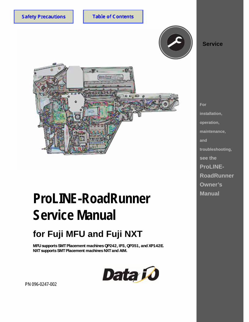
ProLINE-RoadRunner Service Manualfor Fuji MFU and Fuji NXTMFU supports SMT Placement machines QP242, IP3, QP351, and XP142E.NXT supports SMT Placement machines NXT and AIM.
PN 096-0247-002
Service
For
installation,
operation,
maintenance,
and
troubleshooting,
see the
ProLINE-RoadRunner Owner’s Manual

Data I/O has made a conscientious effort to ensure that the information in this document is accurate and complete. Data I/O assumes no liability for errors, or for any incidental, consequential, indirect, or special damages, including, without limitation, loss of use, loss or alteration of data, delays, or lost profits or savings, arising from the use of this document or the product which it accompanies.
No part of this document may be reproduced or transmitted in any form or by any means, electronic or mechanical, for any purpose, without written permission from Data I/O Corporation. Data I/O order forms may be reproduced for internal use only.
Data I/O is a registered trademark of Data I/O Corporation. ProLINE-RoadRunner and TaskLink are trademarks of Data I/O Corporation.
Data I/O Corporation acknowledges the trademarks of other organizations for their respective products or services mentioned in this document.
Data I/O Corporation also acknowledges the RoadRunner team members for their efforts and for supporting the flow of information into this manual.
We are interested in your comments. email: [email protected]
© 2004-2007 Data I/O CorporationAll rights reserved
Data I/O • ProLINE-RoadRunner Service Manual • 096-0247 i
Table of Contents096-0247-002
For non-service information see the Owner’s Manual, 096-0240.
Precautions for Safe Operation 1–iii
Replaceable Modules F–2
Components Overview F–4Component List F–5
Components Overview, NXT Conveyor F–6Component List, NXT Conveyor F–7
Covers F–8Removing the Robotics Cover F–9Removing the PNP Head Cover F–9Removing the Lower Cover F–9Removing the Conveyor Dust Cover F–10Removing the Conveyor Module Cover F–10
Tape-In Module F–12Removing the Adjustable Tape-In Module F–13Removing the Tape-In Module F–15
Pneumatic Module F–18Replacing the Vacuum Filters F–19Removing the Pneumatic Module F–20Reinstalling the Pneumatic Module F–23
Cover Tape Module F–24Removing the Cover Tape Module F–25
Conveyor Module F–26Removing the Conveyor Module F–27Adjusting the Conveyor Drive Belt (Notched Only) F–28Adjusting the End-of-Belt Sensor F–29
Reject Bin F–32Removing the Reject Bin Sensors F–33
ii Data I/O • ProLINE-RoadRunner Service Manual • 096-0247
Control Panel Module F–34Removing the Control Panel Module F–35
Pick and Place Head F–37Aligning the PNP Head F–37Adjusting and Balancing Probe Lowering Speed F–37Adjusting Probe Raising Speed F–38Resetting the Pick Delay and Travel Delay Times F–41Adjusting Probe Vacuum Sensors F–42Removing the PNP Head F–44
Programmer Module F–46Removing the Programmer Module F–47
NVRAM Battery F–54Removing the NVRAM Battery F–55Installing a new NVRAM Battery F–57Reinstalling Components F–57Reteaching the NVRAM F–58
Linear Stage Module F–60Removing the Linear Stage Module F–61
Spare Parts Kits F–63
Basic Spares Kit, Standard RoadRunner F–64Replacing Probe Tips F–65Replacing the Air Inlet Tube Assembly F–65
Self-Service Spares Kit, Standard RoadRunner F–66
Basic Spares Kit, Large Format RoadRunner F–68Replacing Probe Tips F–69Replacing the Air Inlet Tube Assembly F–69
Self-Service Spares Kit, Large Format RoadRunner F–70
Socket Adapter, Actuator, and Precisor F–72
Alphabetical Index Index–1
Data I/O • ProLINE-RoadRunner Service Manual • 096-0247 iii
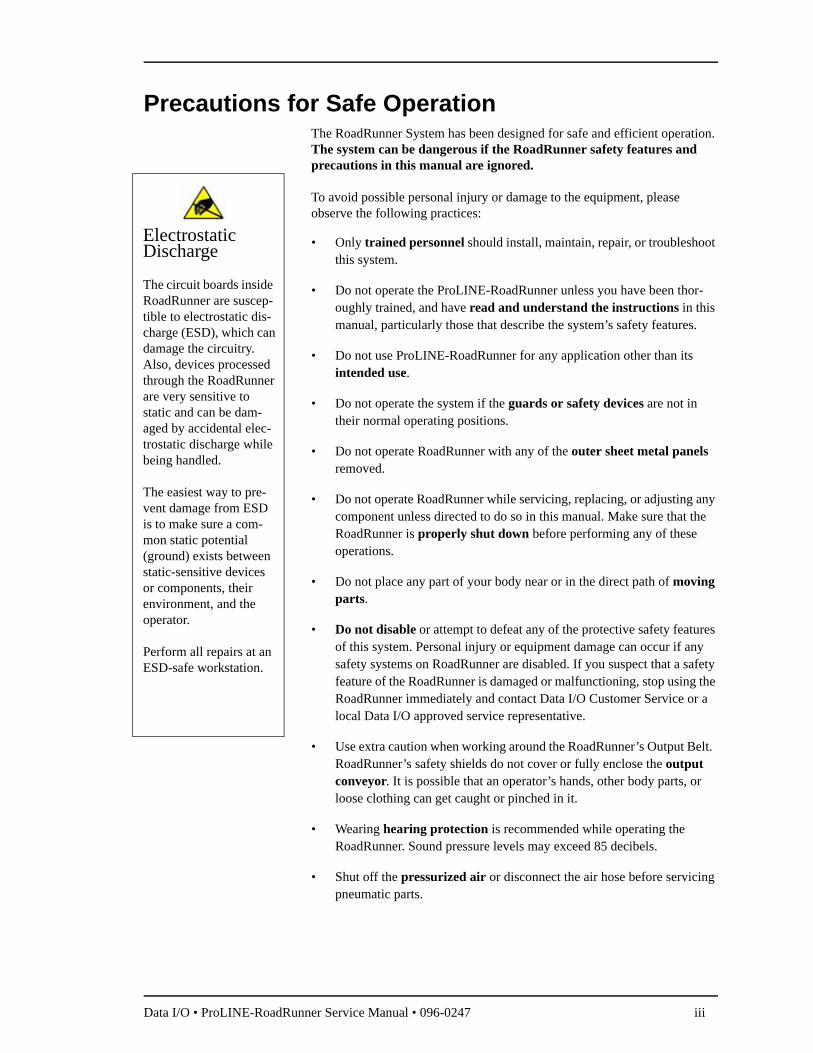
Precautions for Safe OperationThe RoadRunner System has been designed for safe and efficient operation. The system can be dangerous if the RoadRunner safety features and precautions in this manual are ignored.
To avoid possible personal injury or damage to the equipment, please observe the following practices:
• Only trained personnel should install, maintain, repair, or troubleshoot this system.
• Do not operate the ProLINE-RoadRunner unless you have been thor-oughly trained, and have read and understand the instructions in this manual, particularly those that describe the system’s safety features.
• Do not use ProLINE-RoadRunner for any application other than its intended use.
• Do not operate the system if the guards or safety devices are not in their normal operating positions.
• Do not operate RoadRunner with any of the outer sheet metal panels removed.
• Do not operate RoadRunner while servicing, replacing, or adjusting any component unless directed to do so in this manual. Make sure that the RoadRunner is properly shut down before performing any of these operations.
• Do not place any part of your body near or in the direct path of moving parts.
• Do not disable or attempt to defeat any of the protective safety features of this system. Personal injury or equipment damage can occur if any safety systems on RoadRunner are disabled. If you suspect that a safety feature of the RoadRunner is damaged or malfunctioning, stop using the RoadRunner immediately and contact Data I/O Customer Service or a local Data I/O approved service representative.
• Use extra caution when working around the RoadRunner’s Output Belt. RoadRunner’s safety shields do not cover or fully enclose the output conveyor. It is possible that an operator’s hands, other body parts, or loose clothing can get caught or pinched in it.
• Wearing hearing protection is recommended while operating the RoadRunner. Sound pressure levels may exceed 85 decibels.
• Shut off the pressurized air or disconnect the air hose before servicing pneumatic parts.
Electrostatic Discharge
The circuit boards inside RoadRunner are suscep-tible to electrostatic dis-charge (ESD), which can damage the circuitry. Also, devices processed through the RoadRunner are very sensitive to static and can be dam-aged by accidental elec-trostatic discharge while being handled.
The easiest way to pre-vent damage from ESD is to make sure a com-mon static potential (ground) exists between static-sensitive devices or components, their environment, and the operator.
Perform all repairs at an ESD-safe workstation.

iv Data I/O • ProLINE-RoadRunner Service Manual • 096-0247
Blank page.
Data I/O • ProLINE-RoadRunner Service Manual • 096-0247 [updated Aug07] F—1
4Service—Fuji MFU, NXT
This manual supports two models of RoadRunner which support several SMT Placement machines as noted: • RoadRunner/Fuji MFU: QP242, QP351, IP3, XP142E• RoadRunner/Fuji NXT: NXT, AIM
In addition, there is a Large Format (LF) version RoadRunner of each model: MFU and NXT. LF RoadRunners run devices up to 21.65 mm Wide x 24 mm Long x 6 mm High in 32 mm device tape.
Many modules and components on the RoadRunner are designed to be ser-viced or replaced by qualified technicians. You may wish to keep backup modules or components for replacements. The replaced module or compo-nent may be sent to Data I/O for repair or adjustment.
NOTE: Send RoadRunners under warranty back to Data I/O.
If your RoadRunner is NOT under warranty, you have the option of repairing it with instructions in this manual or sending it back to Data I/O. See the inside, back cover for contact information.
Service—Fuji MFU, NXT • Replaceable Modules
F—2 Data I/O • ProLINE-RoadRunner Service Manual • 096-0247 [updated Aug07]
F
F
Replaceable Modules
Some components can be replaced or adjusted at the customer location. Replacement and adjustment procedures for those components are included in this chapter. Some modules can be removed and sent to Data I/O or a local representative for servicing or exchanging.
Within each main section of this chapter is an order form with relevant Sales Names. These names represent the RoadRunner configuration at the time of printing this manual only, and may not be the same as your unit. However, they do correspond to the latest interchangeable replace-ment.
Some of the tools required are • Metric hex keys (Allen wrenches), • a volt meter or multi-meter, • and a metric scale or calipers.
Replaceable modules include:
• Tape-In Module • Pneumatic Module• Conveyor Module • Cover Tape Module• Control Panel Module • PNP Head (subassembly)• Linear Stage Module
(with PNP Head)• Programmer Module
Tools required for RoadRunner maintenance are listed in “Tools Required” in Chapter 5 of the Owner’s Manual.
Service—Fuji MFU, NXT • Replaceable Modules
Data I/O • ProLINE-RoadRunner Service Manual • 096-0247 [updated Aug07] F—3
F
F
blank page
Service—Fuji MFU, NXT • Components Overview
F—4 Data I/O • ProLINE-RoadRunner Service Manual • 096-0247 [updated Aug07]
F
F
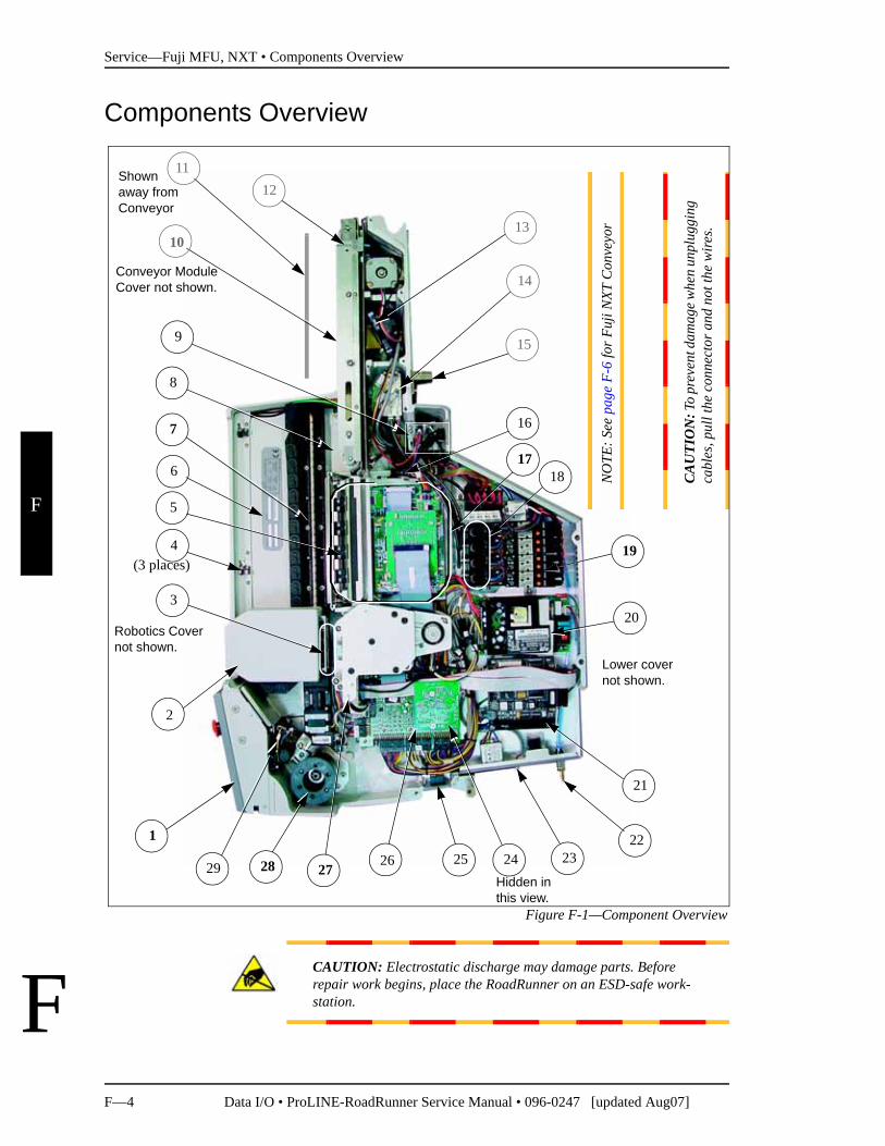
Components Overview
Figure F-1—Component Overview
CAUTION: Electrostatic discharge may damage parts. Before repair work begins, place the RoadRunner on an ESD-safe work-station.
Robotics Cover not shown.
1
17
15
18
22
21
Conveyor Module Cover not shown.
Lower cover not shown.
(3 places)
25
3
12
7
6
11
8
2726 24
2
4
5
14
29
13
9
10
28
16
19
23
20
Shown away from Conveyor
NO
TE: S
ee p
age
F-6
for F
uji N
XT C
onve
yor
CA
UTI
ON
: To
prev
ent d
amag
e whe
n un
plug
ging
ca
bles
, pul
l the
con
nect
or a
nd n
ot th
e w
ires.
Hidden in this view.
Service—Fuji MFU, NXT • Components Overview
Data I/O • ProLINE-RoadRunner Service Manual • 096-0247 [updated Aug07] F—5
F
F
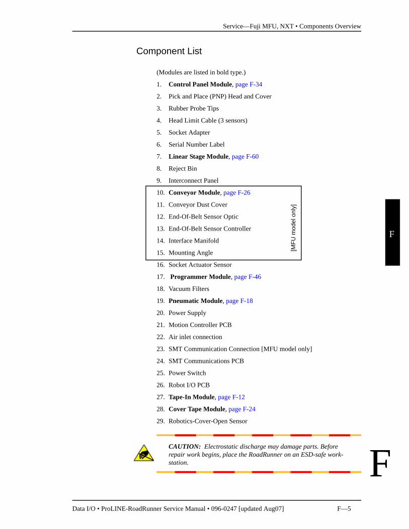
Component List
(Modules are listed in bold type.)
1. Control Panel Module, page F-34
2. Pick and Place (PNP) Head and Cover
3. Rubber Probe Tips
4. Head Limit Cable (3 sensors)
5. Socket Adapter
6. Serial Number Label
7. Linear Stage Module, page F-60
8. Reject Bin
9. Interconnect Panel
10. Conveyor Module, page F-26
11. Conveyor Dust Cover
12. End-Of-Belt Sensor Optic
13. End-Of-Belt Sensor Controller
14. Interface Manifold
15. Mounting Angle
16. Socket Actuator Sensor
17. Programmer Module, page F-46
18. Vacuum Filters
19. Pneumatic Module, page F-18
20. Power Supply
21. Motion Controller PCB
22. Air inlet connection
23. SMT Communication Connection [MFU model only]
24. SMT Communications PCB
25. Power Switch
26. Robot I/O PCB
27. Tape-In Module, page F-12
28. Cover Tape Module, page F-24
29. Robotics-Cover-Open Sensor
CAUTION: Electrostatic discharge may damage parts. Before repair work begins, place the RoadRunner on an ESD-safe work-station.
[MFU
mod
el o
nly]
Service—Fuji MFU, NXT • Components Overview, NXT Conveyor
F—6 Data I/O • ProLINE-RoadRunner Service Manual • 096-0247 [updated Aug07]
F
F
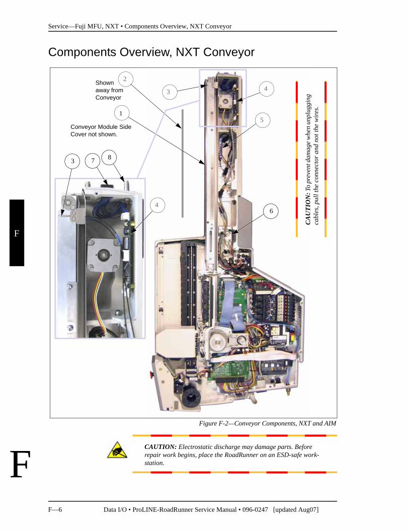
Components Overview, NXT Conveyor
Figure F-2—Conveyor Components, NXT and AIM
CAUTION: Electrostatic discharge may damage parts. Before repair work begins, place the RoadRunner on an ESD-safe work-station.
4
Conveyor Module Side Cover not shown.
3
5
6
Shown away from Conveyor
CA
UTI
ON
: To
prev
ent d
amag
e whe
n un
plug
ging
ca
bles
, pul
l the
con
nect
or a
nd n
ot th
e w
ires.
7 83
1
2
4
Service—Fuji MFU, NXT • Components Overview, NXT Conveyor
Data I/O • ProLINE-RoadRunner Service Manual • 096-0247 [updated Aug07] F—7
F
F
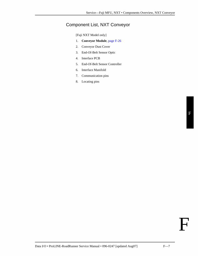
Component List, NXT Conveyor
[Fuji NXT Model only]
1. Conveyor Module, page F-26
2. Conveyor Dust Cover
3. End-Of-Belt Sensor Optic
4. Interface PCB
5. End-Of-Belt Sensor Controller
6. Interface Manifold
7. Communication pins
8. Locating pins
Service—Fuji MFU, NXT • Covers
F—8 Data I/O • ProLINE-RoadRunner Service Manual • 096-0247 [updated Aug07]
F
F
Covers
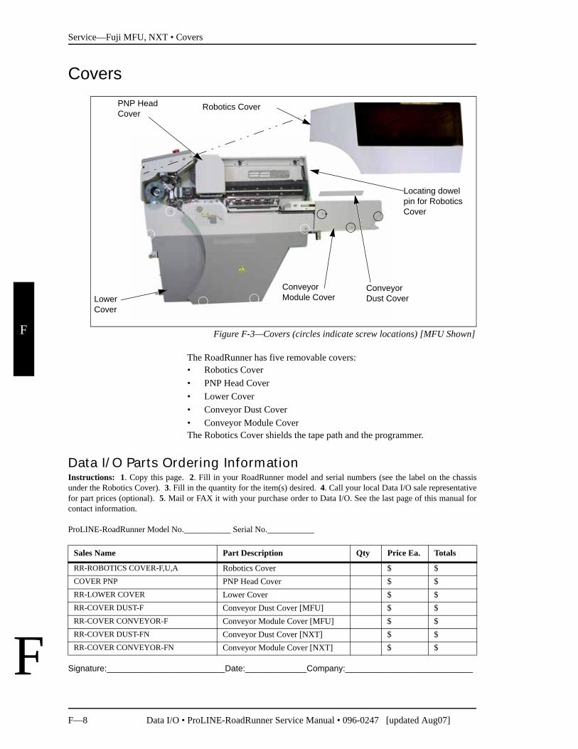
Figure F-3—Covers (circles indicate screw locations) [MFU Shown]
The RoadRunner has five removable covers:• Robotics Cover• PNP Head Cover• Lower Cover• Conveyor Dust Cover• Conveyor Module CoverThe Robotics Cover shields the tape path and the programmer.
Signature:_________________________Date:_____________Company:___________________________
PNP Head Cover
Conveyor Module Cover
Conveyor Dust Cover
Robotics Cover
Lower Cover
Locating dowel pin for Robotics Cover
Data I/O Parts Ordering InformationInstructions: 1. Copy this page. 2. Fill in your RoadRunner model and serial numbers (see the label on the chassisunder the Robotics Cover). 3. Fill in the quantity for the item(s) desired. 4. Call your local Data I/O sale representativefor part prices (optional). 5. Mail or FAX it with your purchase order to Data I/O. See the last page of this manual forcontact information.
ProLINE-RoadRunner Model No.___________ Serial No.___________
Sales Name Part Description Qty Price Ea. Totals
RR-ROBOTICS COVER-F,U,A Robotics Cover $ $COVER PNP PNP Head Cover $ $RR-LOWER COVER Lower Cover $ $RR-COVER DUST-F Conveyor Dust Cover [MFU] $ $RR-COVER CONVEYOR-F Conveyor Module Cover [MFU] $ $RR-COVER DUST-FN Conveyor Dust Cover [NXT] $ $RR-COVER CONVEYOR-FN Conveyor Module Cover [NXT] $ $
Service—Fuji MFU, NXT • Covers
Data I/O • ProLINE-RoadRunner Service Manual • 096-0247 [updated Aug07] F—9
F
F
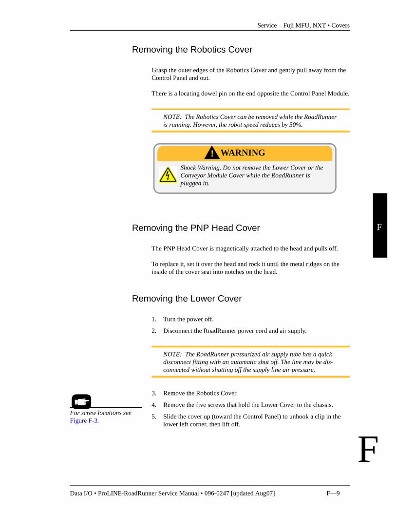
Removing the Robotics Cover
Grasp the outer edges of the Robotics Cover and gently pull away from the Control Panel and out.
There is a locating dowel pin on the end opposite the Control Panel Module.
NOTE: The Robotics Cover can be removed while the RoadRunner is running. However, the robot speed reduces by 50%.
Removing the PNP Head Cover
The PNP Head Cover is magnetically attached to the head and pulls off.
To replace it, set it over the head and rock it until the metal ridges on the inside of the cover seat into notches on the head.
Removing the Lower Cover
1. Turn the power off.
2. Disconnect the RoadRunner power cord and air supply.
NOTE: The RoadRunner pressurized air supply tube has a quick disconnect fitting with an automatic shut off. The line may be dis-connected without shutting off the supply line air pressure.
3. Remove the Robotics Cover.
4. Remove the five screws that hold the Lower Cover to the chassis.
5. Slide the cover up (toward the Control Panel) to unhook a clip in the lower left corner, then lift off.
Shock Warning. Do not remove the Lower Cover or the Conveyor Module Cover while the RoadRunner is plugged in.
WARNING!
For screw locations see Figure F-3.
Service—Fuji MFU, NXT • Covers
F—10 Data I/O • ProLINE-RoadRunner Service Manual • 096-0247 [updated Aug07]
F
F
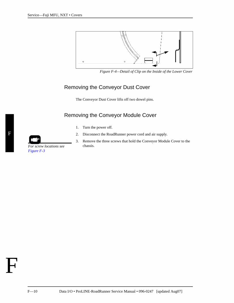
Figure F-4—Detail of Clip on the Inside of the Lower Cover
Removing the Conveyor Dust Cover
The Conveyor Dust Cover lifts off two dowel pins.
Removing the Conveyor Module Cover
1. Turn the power off.
2. Disconnect the RoadRunner power cord and air supply.
3. Remove the three screws that hold the Conveyor Module Cover to the chassis. For screw locations see
Figure F-3

Service—Fuji MFU, NXT • Covers
Data I/O • ProLINE-RoadRunner Service Manual • 096-0247 [updated Aug07] F—11
F
F
Blank page.
Service—Fuji MFU, NXT • Tape-In Module
F—12 Data I/O • ProLINE-RoadRunner Service Manual • 096-0247 [updated Aug07]
F
F
Tape-In Module
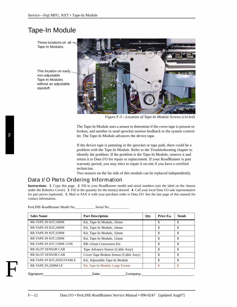
Figure F-5—Location of Tape-In Module Screws (circled)
The Tape-In Module uses a sensor to determine if the cover tape is present or broken, and another to send sprocket motion feedback to the system control-ler. The Tape-In Module advances the device tape.
If the device tape is jamming in the sprocket or tape path, there could be a problem with the Tape-In Module. Refer to the Troubleshooting chapter to identify the problem. If the problem is the Tape-In Module, remove it and return it to Data I/O for repair or replacement. If your RoadRunner is past warranty period, you may elect to repair it on-site if you have a certified technician.Two sensors on the far side of this module can be replaced independently.
Signature:_________________________Date:_____________Company:___________________________
This location on early, non-adjustable Tape-In Modules without an adjustable standoff.
These locations on all Tape-In Modules.
Data I/O Parts Ordering InformationInstructions: 1. Copy this page. 2. Fill in your RoadRunner model and serial numbers (see the label on the chassisunder the Robotics Cover). 3. Fill in the quantity for the item(s) desired. 4. Call your local Data I/O sale representativefor part prices (optional). 5. Mail or FAX it with your purchase order to Data I/O. See the last page of this manual forcontact information.
ProLINE-RoadRunner Model No.___________ Serial No.___________
Sales Name Part Description Qty Price Ea. Totals
RR-TAPE-IN KIT,16MM Kit, Tape-In Module, 16mm $ $RR-TAPE-IN KIT,24MM Kit, Tape-In Module, 24mm $ $RR-TAPE-IN KIT,32MM Kit, Tape-In Module, 32mm $ $RR-TAPE-IN KIT,12MM Kit, Tape-In Module, 12mm $ $RR-TAPE-IN KIT,12MM 12/06 RR-12mm Conversion Kit $ $RR-SLOT SENSOR CAB Tape Advance Sensor (Cable Assy) $ $RR-SLOT SENSOR CAB Cover Tape Broken Sensor (Cable Assy) $ $RR-TAPE-IN KIT,ADJUSTABLE Kit, Adjustable Tape-In Module $ $RR-TAPE IN,32MM-LF Kit, Tape-In Module, Large Format $ $
Service—Fuji MFU, NXT • Tape-In Module
Data I/O • ProLINE-RoadRunner Service Manual • 096-0247 [updated Aug07] F—13
F
F
Removing the Adjustable Tape-In Module
NOTE: (For the Standard Tape-In Module, see “Removing the Tape-In Module” on page F-15.)
1. Turn the power off.
2. Disconnect the RoadRunner power cord and air supply.
3. Remove the Robotics Cover and Lower Cover.
4. Remove the two screws attaching the Tape Guide to the Adjustable Tape-In (ATI) Module (required only if exchanging the module).
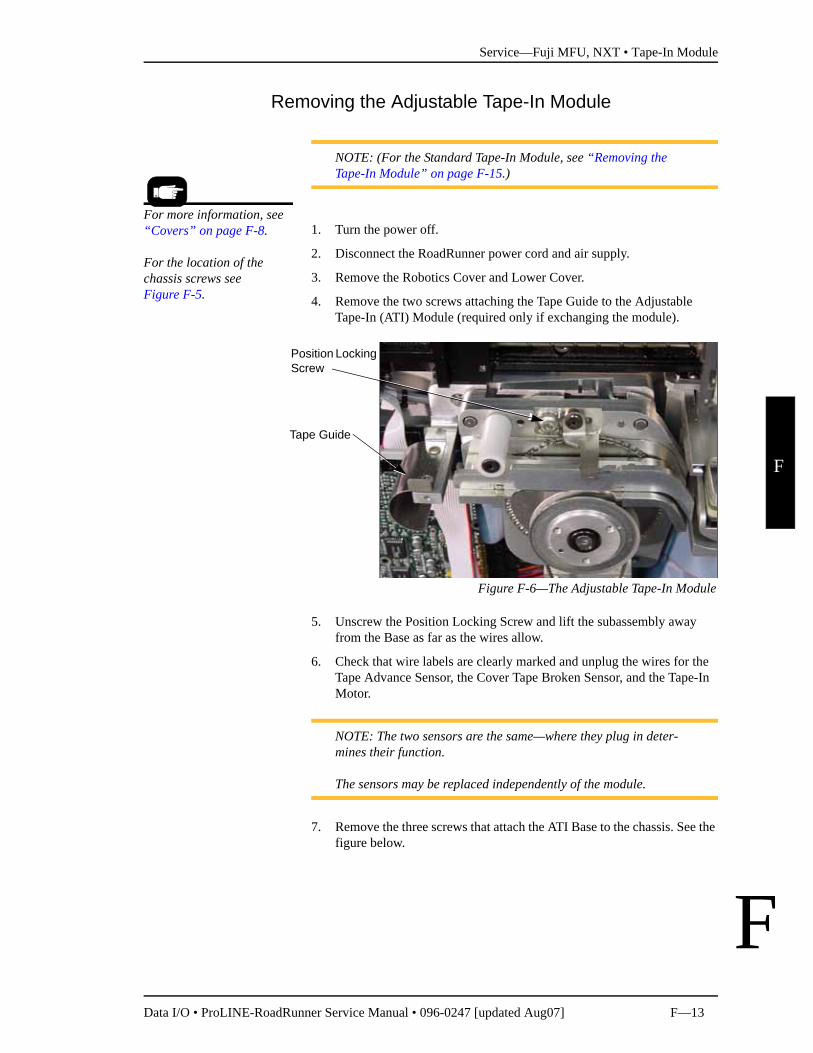
Figure F-6—The Adjustable Tape-In Module
5. Unscrew the Position Locking Screw and lift the subassembly away from the Base as far as the wires allow.
6. Check that wire labels are clearly marked and unplug the wires for the Tape Advance Sensor, the Cover Tape Broken Sensor, and the Tape-In Motor.
NOTE: The two sensors are the same—where they plug in deter-mines their function.
The sensors may be replaced independently of the module.
7. Remove the three screws that attach the ATI Base to the chassis. See the figure below.
For more information, see “Covers” on page F-8.
For the location of the chassis screws see Figure F-5.
Position Locking Screw
Tape Guide
Service—Fuji MFU, NXT • Tape-In Module
F—14 Data I/O • ProLINE-RoadRunner Service Manual • 096-0247 [updated Aug07]
F
F
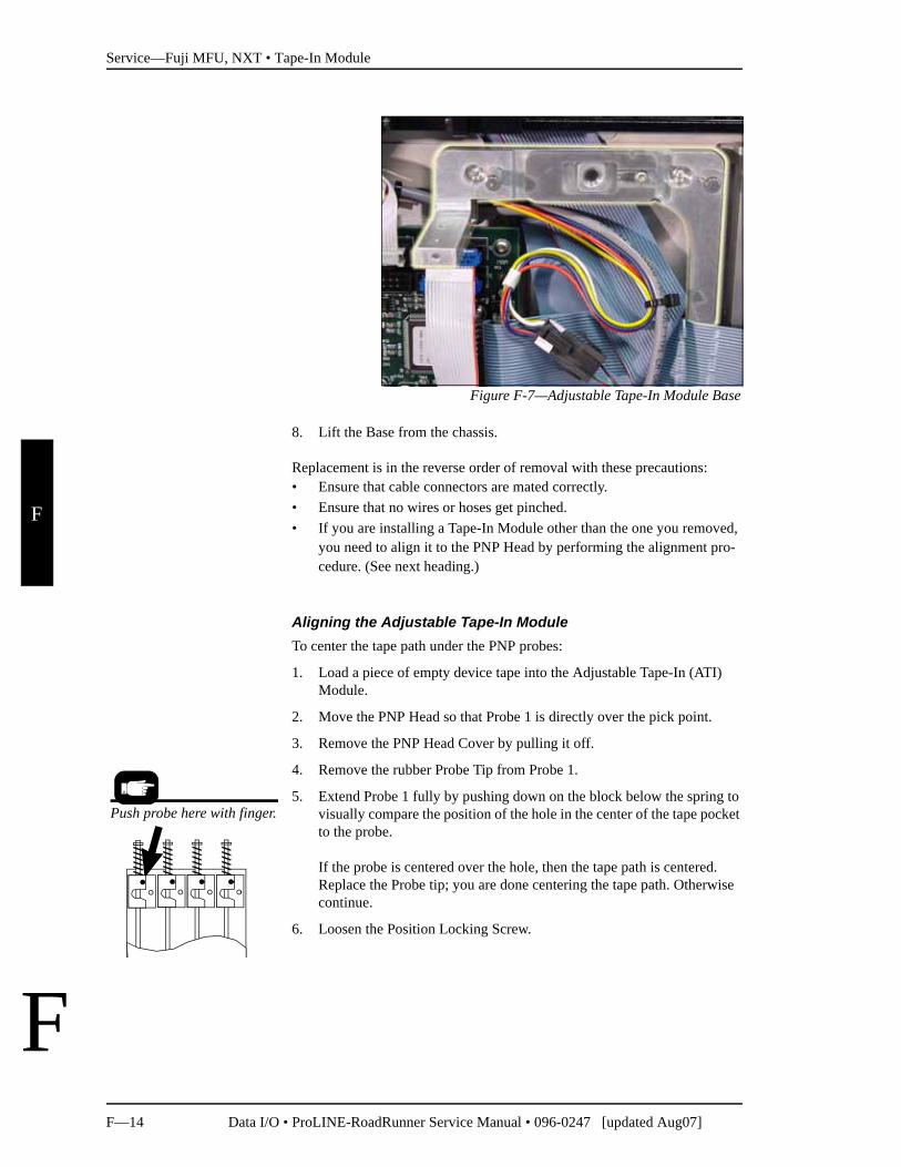
Figure F-7—Adjustable Tape-In Module Base
8. Lift the Base from the chassis.
Replacement is in the reverse order of removal with these precautions:• Ensure that cable connectors are mated correctly.• Ensure that no wires or hoses get pinched.• If you are installing a Tape-In Module other than the one you removed,
you need to align it to the PNP Head by performing the alignment pro-cedure. (See next heading.)
Aligning the Adjustable Tape-In ModuleTo center the tape path under the PNP probes:
1. Load a piece of empty device tape into the Adjustable Tape-In (ATI) Module.
2. Move the PNP Head so that Probe 1 is directly over the pick point.
3. Remove the PNP Head Cover by pulling it off.
4. Remove the rubber Probe Tip from Probe 1.
5. Extend Probe 1 fully by pushing down on the block below the spring to visually compare the position of the hole in the center of the tape pocket to the probe.
If the probe is centered over the hole, then the tape path is centered. Replace the Probe tip; you are done centering the tape path. Otherwise continue.
6. Loosen the Position Locking Screw.
Push probe here with finger.
Service—Fuji MFU, NXT • Tape-In Module
Data I/O • ProLINE-RoadRunner Service Manual • 096-0247 [updated Aug07] F—15
F
F
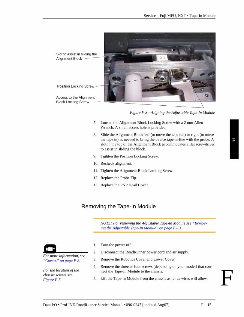
Figure F-8—Aligning the Adjustable Tape-In Module
7. Loosen the Alignment Block Locking Screw with a 2 mm Allen Wrench. A small access hole is provided.
8. Slide the Alignment Block left (to move the tape out) or right (to move the tape in) as needed to bring the device tape in-line with the probe. A slot in the top of the Alignment Block accommodates a flat screwdriver to assist in sliding the block.
9. Tighten the Position Locking Screw.
10. Recheck alignment.
11. Tighten the Alignment Block Locking Screw.
12. Replace the Probe Tip.
13. Replace the PNP Head Cover.
Removing the Tape-In Module
NOTE: For removing the Adjustable Tape-In Module see “Remov-ing the Adjustable Tape-In Module” on page F-13.
1. Turn the power off.
2. Disconnect the RoadRunner power cord and air supply.
3. Remove the Robotics Cover and Lower Cover.
4. Remove the three or four screws (depending on your model) that con-nect the Tape-In Module to the chassis.
5. Lift the Tape-In Module from the chassis as far as wires will allow.
Access to the Alignment Block Locking Screw
Slot to assist in sliding the Alignment Block
Position Locking Screw
For more information, see “Covers” on page F-8.
For the location of the chassis screws see Figure F-5.
Service—Fuji MFU, NXT • Tape-In Module
F—16 Data I/O • ProLINE-RoadRunner Service Manual • 096-0247 [updated Aug07]
F
F
NOTE: The 16mm and 24mm Tape-In Modules have spacers that could fall out. They must be saved and reused on reinstallation.
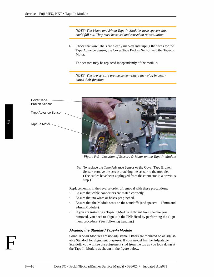
6. Check that wire labels are clearly marked and unplug the wires for the Tape Advance Sensor, the Cover Tape Broken Sensor, and the Tape-In Motor.
The sensors may be replaced independently of the module.
NOTE: The two sensors are the same—where they plug in deter-mines their function.
Figure F-9—Location of Sensors & Motor on the Tape-In Module
6a. To replace the Tape Advance Sensor or the Cover Tape Broken Sensor, remove the screw attaching the sensor to the module. (The cables have been unplugged from the connector in a previous step.)
Replacement is in the reverse order of removal with these precautions:• Ensure that cable connectors are mated correctly.• Ensure that no wires or hoses get pinched.• Ensure that the Module seats on the standoffs (and spacers—16mm and
24mm Modules).• If you are installing a Tape-In Module different from the one you
removed, you need to align it to the PNP Head by performing the align-ment procedure. (See following heading.)
Aligning the Standard Tape-In ModuleSome Tape-In Modules are not adjustable. Others are mounted on an adjust-able Standoff for alignment purposes. If your model has the Adjustable Standoff, you will see the adjustment stud from the top as you look down at the Tape-In Module as shown in the figure below.
Tape-In Motor
Tape Advance Sensor
Cover Tape Broken Sensor
Service—Fuji MFU, NXT • Tape-In Module
Data I/O • ProLINE-RoadRunner Service Manual • 096-0247 [updated Aug07] F—17
F
F
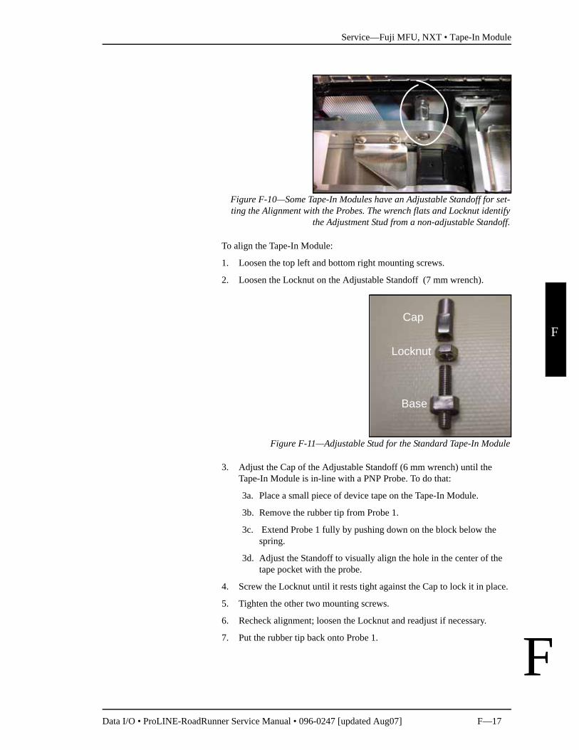
Figure F-10—Some Tape-In Modules have an Adjustable Standoff for set-ting the Alignment with the Probes. The wrench flats and Locknut identify
the Adjustment Stud from a non-adjustable Standoff.
To align the Tape-In Module:
1. Loosen the top left and bottom right mounting screws.
2. Loosen the Locknut on the Adjustable Standoff (7 mm wrench).
Figure F-11—Adjustable Stud for the Standard Tape-In Module
3. Adjust the Cap of the Adjustable Standoff (6 mm wrench) until the Tape-In Module is in-line with a PNP Probe. To do that:
3a. Place a small piece of device tape on the Tape-In Module.
3b. Remove the rubber tip from Probe 1.
3c. Extend Probe 1 fully by pushing down on the block below the spring.
3d. Adjust the Standoff to visually align the hole in the center of the tape pocket with the probe.
4. Screw the Locknut until it rests tight against the Cap to lock it in place.
5. Tighten the other two mounting screws.
6. Recheck alignment; loosen the Locknut and readjust if necessary.
7. Put the rubber tip back onto Probe 1.
Cap
Locknut
Base
Service—Fuji MFU, NXT • Pneumatic Module
F—18 Data I/O • ProLINE-RoadRunner Service Manual • 096-0247 [updated Aug07]
F
F
Pneumatic Module
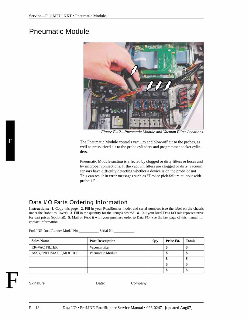
Figure F-12—Pneumatic Module and Vacuum Filter Locations
The Pneumatic Module controls vacuum and blow-off air to the probes, as well as pressurized air to the probe cylinders and programmer socket cylin-ders.
Pneumatic Module suction is affected by clogged or dirty filters or hoses and by improper connections. If the vacuum filters are clogged or dirty, vacuum sensors have difficulty detecting whether a device is on the probe or not. This can result in error messages such as “Device pick failure at input with probe 1.”
Signature:_________________________Date:_____________Company:___________________________
Data I/O Parts Ordering InformationInstructions: 1. Copy this page. 2. Fill in your RoadRunner model and serial numbers (see the label on the chassisunder the Robotics Cover). 3. Fill in the quantity for the item(s) desired. 4. Call your local Data I/O sale representativefor part prices (optional). 5. Mail or FAX it with your purchase order to Data I/O. See the last page of this manual forcontact information.
ProLINE-RoadRunner Model No.___________ Serial No.___________
Sales Name Part Description Qty Price Ea. Totals
RR-VAC FILTER Vacuum filter $ $ASSY,PNEUMATIC,MODULE Pneumatic Module $ $
$ $$ $$ $
Service—Fuji MFU, NXT • Pneumatic Module
Data I/O • ProLINE-RoadRunner Service Manual • 096-0247 [updated Aug07] F—19
F
F
If you experience problems such as dropped devices or pick failures, replace the vacuum filters (page F-19), adjust the vacuum sensor (page F-42), or see the chapter on “Troubleshooting” in the Owner’s Manual.
NOTE: In normal low-dust conditions, Vacuum Filters must be replaced every 6 months. Replacement may need to be done more frequently in dustier environments.
Replacing the Vacuum Filters
1. Turn the power off.
2. Disconnect the RoadRunner power cord and air supply.
3. Remove the Robotics and Lower Covers.
4. Remove the square plastic housings with the Vacuum Filters by unscrewing the thumbscrews from the valve block.
NOTE: Ensure that the gasket between the housing and the valve block does not fall out during removal or installation of the hous-ing. If it does, install the gasket into the groove on the valve block.
CAUTION: The housing has two locating pins. To prevent damage, orient the housing correctly when reinstalling.
For more informations, see “Covers” on page F-8.
Service—Fuji MFU, NXT • Pneumatic Module
F—20 Data I/O • ProLINE-RoadRunner Service Manual • 096-0247 [updated Aug07]
F
F
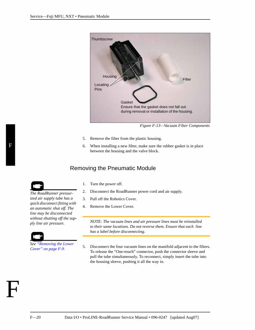
Figure F-13—Vacuum Filter Components
5. Remove the filter from the plastic housing.
6. When installing a new filter, make sure the rubber gasket is in place between the housing and the valve block.
Removing the Pneumatic Module
1. Turn the power off.
2. Disconnect the RoadRunner power cord and air supply.
3. Pull off the Robotics Cover.
4. Remove the Lower Cover.
NOTE: The vacuum lines and air pressure lines must be reinstalled to their same locations. Do not reverse them. Ensure that each line has a label before disconnecting.
5. Disconnect the four vacuum lines on the manifold adjacent to the filters.To release the “One-touch” connector, push the connector sleeve and pull the tube simultaneously. To reconnect, simply insert the tube into the housing sleeve, pushing it all the way in.
FilterHousing
GasketEnsure that the gasket does not fall out during removal or installation of the housing.
Thumbscrew
Locating Pins
The RoadRunner pressur-ized air supply tube has a quick disconnect fitting with an automatic shut off. The line may be disconnected without shutting off the sup-ply line air pressure.
See “Removing the Lower Cover” on page F-9.
Service—Fuji MFU, NXT • Pneumatic Module
Data I/O • ProLINE-RoadRunner Service Manual • 096-0247 [updated Aug07] F—21
F
F
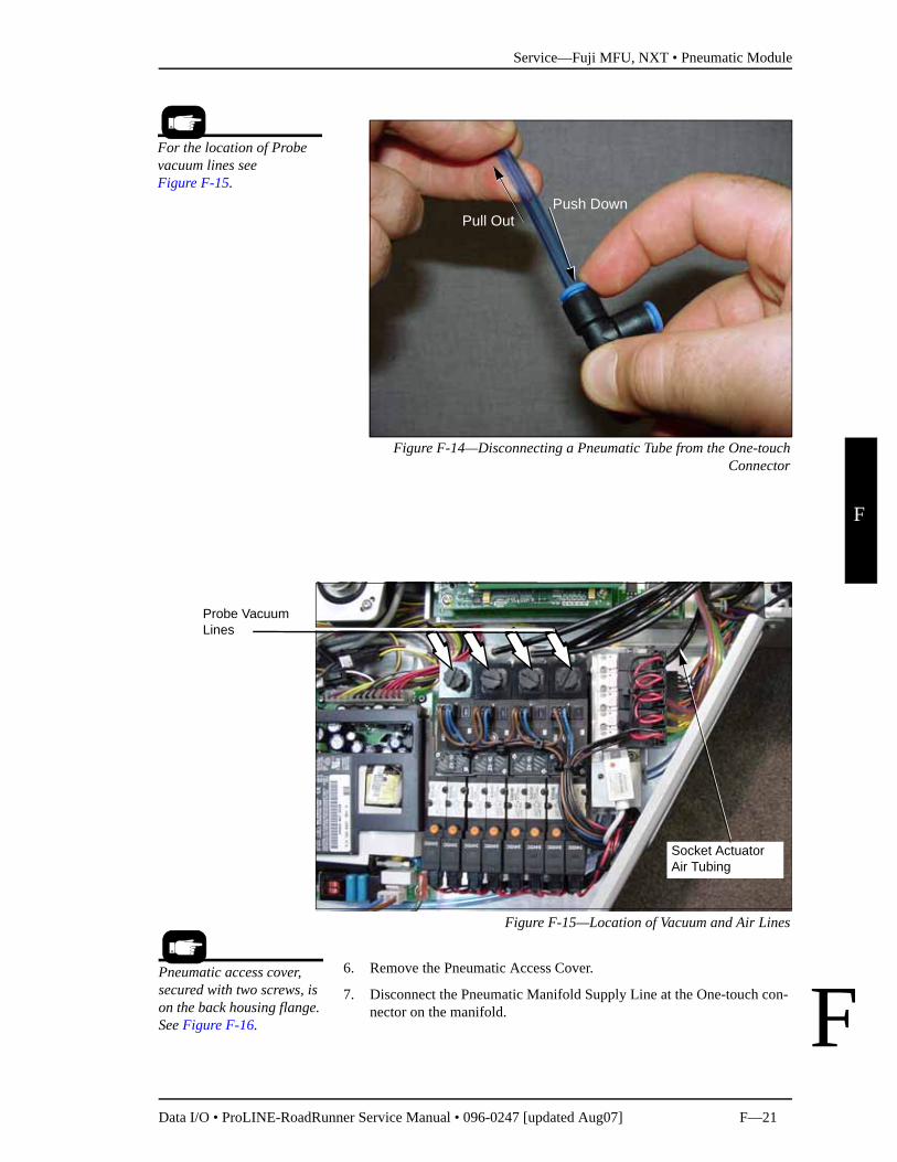
Figure F-14—Disconnecting a Pneumatic Tube from the One-touchConnector
Figure F-15—Location of Vacuum and Air Lines
6. Remove the Pneumatic Access Cover.
7. Disconnect the Pneumatic Manifold Supply Line at the One-touch con-nector on the manifold.
Push DownPull Out
For the location of Probe vacuum lines see Figure F-15.
Probe Vacuum Lines
Socket ActuatorAir Tubing
Pneumatic access cover, secured with two screws, is on the back housing flange. See Figure F-16.
Service—Fuji MFU, NXT • Pneumatic Module
F—22 Data I/O • ProLINE-RoadRunner Service Manual • 096-0247 [updated Aug07]
F
F
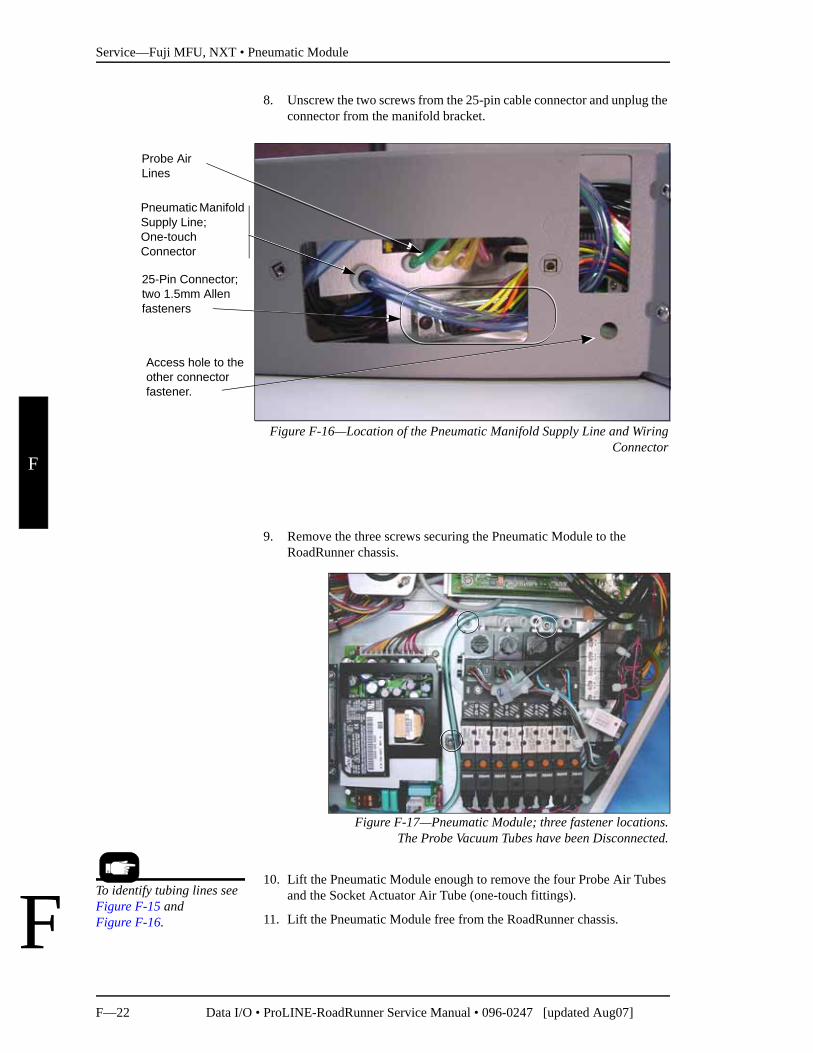
8. Unscrew the two screws from the 25-pin cable connector and unplug the connector from the manifold bracket.
Figure F-16—Location of the Pneumatic Manifold Supply Line and WiringConnector
9. Remove the three screws securing the Pneumatic Module to the RoadRunner chassis.
Figure F-17—Pneumatic Module; three fastener locations.The Probe Vacuum Tubes have been Disconnected.
10. Lift the Pneumatic Module enough to remove the four Probe Air Tubes and the Socket Actuator Air Tube (one-touch fittings).
11. Lift the Pneumatic Module free from the RoadRunner chassis.
Pneumatic Manifold Supply Line;One-touch Connector
Access hole to the other connector fastener.
Probe AirLines
25-Pin Connector;two 1.5mm Allen fasteners
To identify tubing lines see Figure F-15 and Figure F-16.
Service—Fuji MFU, NXT • Pneumatic Module
Data I/O • ProLINE-RoadRunner Service Manual • 096-0247 [updated Aug07] F—23
F
F
Reinstalling the Pneumatic Module
Installation is done in the reverse order of removal; then the following post-installation adjustments are required:
1. At the Control Panel, verify proper electrical and pneumatic connec-tions as follows:
1a. Extend and retract each probe to verify correct plumbing. Robot Diagnostics » Probe X » Position » Arrow Up/Down.
1b. Enable vacuum to each probe to verify correct plumbing. Robot Diagnostics » Probe X » Vac Sense » Arrow Up/Down.
1c. Enable probe “Puff” and verify correct switching of positive air pressure at the probe tips. Robot Diagnostics » Probe 1 » Puff » Up/Down Arrow.
2. Adjust the probe vacuum sensors.
3. Adjust probe speed.For step 2 see“Adjusting Probe Vacuum Sensors” on page F-42.
For step 3 see “Adjusting and Balancing Probe Low-ering Speed” on page F-37.
Service—Fuji MFU, NXT • Cover Tape Module
F—24 Data I/O • ProLINE-RoadRunner Service Manual • 096-0247 [updated Aug07]
F
F
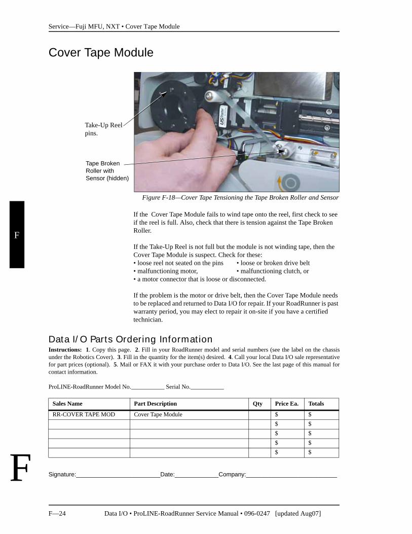
Cover Tape Module
Figure F-18—Cover Tape Tensioning the Tape Broken Roller and Sensor
If the Cover Tape Module fails to wind tape onto the reel, first check to see if the reel is full. Also, check that there is tension against the Tape Broken Roller.
If the Take-Up Reel is not full but the module is not winding tape, then the Cover Tape Module is suspect. Check for these:• loose reel not seated on the pins • loose or broken drive belt • malfunctioning motor, • malfunctioning clutch, or • a motor connector that is loose or disconnected.
If the problem is the motor or drive belt, then the Cover Tape Module needs to be replaced and returned to Data I/O for repair. If your RoadRunner is past warranty period, you may elect to repair it on-site if you have a certified technician.
Signature:_________________________Date:_____________Company:___________________________
Tape Broken Roller with Sensor (hidden)
Take-Up Reel pins.
Data I/O Parts Ordering InformationInstructions: 1. Copy this page. 2. Fill in your RoadRunner model and serial numbers (see the label on the chassisunder the Robotics Cover). 3. Fill in the quantity for the item(s) desired. 4. Call your local Data I/O sale representativefor part prices (optional). 5. Mail or FAX it with your purchase order to Data I/O. See the last page of this manual forcontact information.
ProLINE-RoadRunner Model No.___________ Serial No.___________
Sales Name Part Description Qty Price Ea. Totals
RR-COVER TAPE MOD Cover Tape Module $ $$ $$ $$ $$ $
Service—Fuji MFU, NXT • Cover Tape Module
Data I/O • ProLINE-RoadRunner Service Manual • 096-0247 [updated Aug07] F—25
F
F
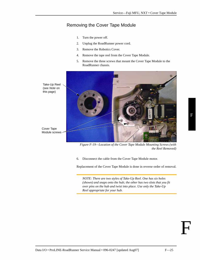
Removing the Cover Tape Module
1. Turn the power off.
2. Unplug the RoadRunner power cord.
3. Remove the Robotics Cover.
4. Remove the tape reel from the Cover Tape Module.
5. Remove the three screws that mount the Cover Tape Module to the RoadRunner chassis.
Figure F-19—Location of the Cover Tape Module Mounting Screws (withthe Reel Removed)
6. Disconnect the cable from the Cover Tape Module motor.
Replacement of the Cover Tape Module is done in reverse order of removal.
NOTE: There are two styles of Take-Up Reel. One has six holes (shown) and snaps onto the hub; the other has two slots that you fit over pins on the hub and twist into place. Use only the Take-Up Reel appropriate for your hub.
Take-Up Reel(see Note on this page)
Cover Tape Module screws
Service—Fuji MFU, NXT • Conveyor Module
F—26 Data I/O • ProLINE-RoadRunner Service Manual • 096-0247 [updated Aug07]
F
F
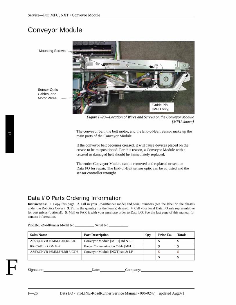
Conveyor Module
Figure F-20—Location of Wires and Screws on the Conveyor Module[MFU shown]
The conveyor belt, the belt motor, and the End-of-Belt Sensor make up the main parts of the Conveyor Module.
If the conveyor belt becomes creased, it will cause devices placed on the crease to be mispositioned. For this reason, a Conveyor Module with a creased or damaged belt should be immediately replaced.
The entire Conveyor Module can be removed and replaced or sent to Data I/O for repair. The End-of-Belt sensor optic can be adjusted and the sensor controller retaught.
Signature:_________________________Date:_____________Company:___________________________
Sensor OpticCables, and Motor Wires.
Mounting Screws
Guide Pin[MFU only]
Data I/O Parts Ordering InformationInstructions: 1. Copy this page. 2. Fill in your RoadRunner model and serial numbers (see the label on the chassisunder the Robotics Cover). 3. Fill in the quantity for the item(s) desired. 4. Call your local Data I/O sale representativefor part prices (optional). 5. Mail or FAX it with your purchase order to Data I/O. See the last page of this manual forcontact information.
ProLINE-RoadRunner Model No.___________ Serial No.___________
Sales Name Part Description Qty Price Ea. Totals
ASSY,CNVR 16MM,FUJI,RR-UC Conveyor Module [MFU] std & LF $ $RR-CABLE COMM-F Feeder Communication Cable [MFU] $ $ASSY,CNVR 16MM,FN,RR-UC??? Conveyor Module [NXT] std & LF $ $
$ $
Service—Fuji MFU, NXT • Conveyor Module
Data I/O • ProLINE-RoadRunner Service Manual • 096-0247 [updated Aug07] F—27
F
F
Removing the Conveyor Module
1. Turn the power off.
2. Disconnect the RoadRunner power cord and air supply.
3. Lift off the Conveyor Dust Cover.
4. Remove the Conveyor Module Cover.
5. Cut the tie wraps securing the wires for the belt motor, communications, and sensors.
CAUTION: Optic cables are fragile and may break. Do not bend radically.
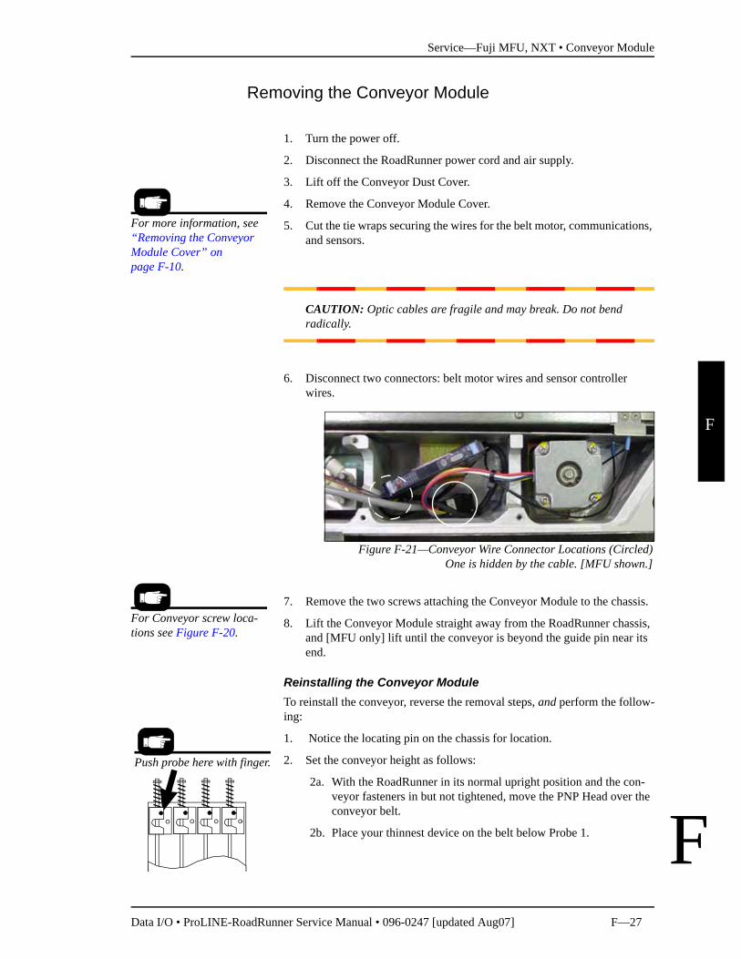
6. Disconnect two connectors: belt motor wires and sensor controller wires.
Figure F-21—Conveyor Wire Connector Locations (Circled)One is hidden by the cable. [MFU shown.]
7. Remove the two screws attaching the Conveyor Module to the chassis.
8. Lift the Conveyor Module straight away from the RoadRunner chassis, and [MFU only] lift until the conveyor is beyond the guide pin near its end.
Reinstalling the Conveyor ModuleTo reinstall the conveyor, reverse the removal steps, and perform the follow-ing:
1. Notice the locating pin on the chassis for location.
2. Set the conveyor height as follows:
2a. With the RoadRunner in its normal upright position and the con-veyor fasteners in but not tightened, move the PNP Head over the conveyor belt.
2b. Place your thinnest device on the belt below Probe 1.
For more information, see “Removing the Conveyor Module Cover” on page F-10.
For Conveyor screw loca-tions see Figure F-20.
Push probe here with finger.
Service—Fuji MFU, NXT • Conveyor Module
F—28 Data I/O • ProLINE-RoadRunner Service Manual • 096-0247 [updated Aug07]
F
F
2c. Lower Probe 1 fully (pushing on the block below the spring). Adjust the conveyor height so that the probe tip just barely con-tacts the device on the belt, then tighten the fasteners.
2d. Recheck the height after tightening the fasteners.
Adjusting the Conveyor Drive Belt (Notched Only)
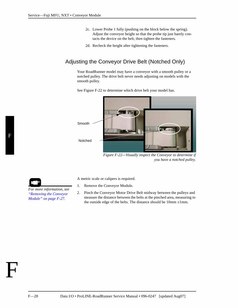
Your RoadRunner model may have a conveyor with a smooth pulley or a notched pulley. The drive belt never needs adjusting on models with the smooth pulley.
See Figure F-22 to determine which drive belt your model has.
Figure F-22—Visually inspect the Conveyor to determine ifyou have a notched pulley.
A metric scale or calipers is required.
1. Remove the Conveyor Module.
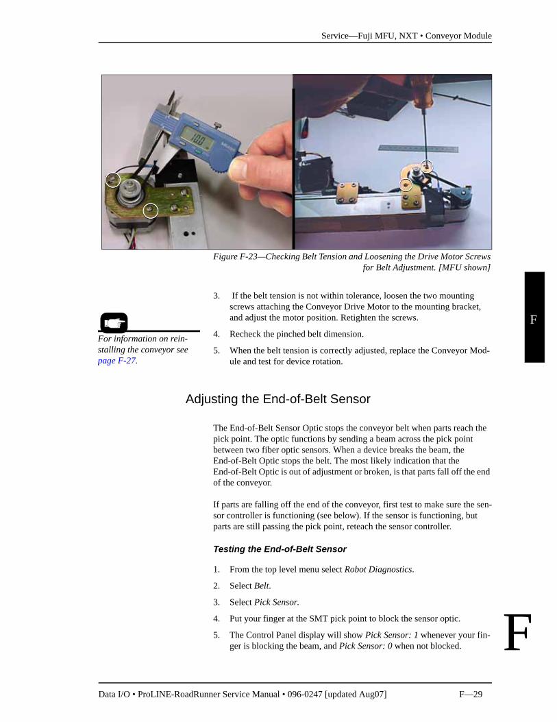
2. Pinch the Conveyor Motor Drive Belt midway between the pulleys and measure the distance between the belts at the pinched area, measuring to the outside edge of the belts. The distance should be 10mm ±1mm.
Smooth
Notched
For more information, see “Removing the Conveyor Module” on page F-27.
Service—Fuji MFU, NXT • Conveyor Module
Data I/O • ProLINE-RoadRunner Service Manual • 096-0247 [updated Aug07] F—29
F
F
Figure F-23—Checking Belt Tension and Loosening the Drive Motor Screwsfor Belt Adjustment. [MFU shown]
3. If the belt tension is not within tolerance, loosen the two mounting screws attaching the Conveyor Drive Motor to the mounting bracket, and adjust the motor position. Retighten the screws.
4. Recheck the pinched belt dimension.
5. When the belt tension is correctly adjusted, replace the Conveyor Mod-ule and test for device rotation.
Adjusting the End-of-Belt Sensor
The End-of-Belt Sensor Optic stops the conveyor belt when parts reach the pick point. The optic functions by sending a beam across the pick point between two fiber optic sensors. When a device breaks the beam, the End-of-Belt Optic stops the belt. The most likely indication that the End-of-Belt Optic is out of adjustment or broken, is that parts fall off the end of the conveyor.
If parts are falling off the end of the conveyor, first test to make sure the sen-sor controller is functioning (see below). If the sensor is functioning, but parts are still passing the pick point, reteach the sensor controller.
Testing the End-of-Belt Sensor
1. From the top level menu select Robot Diagnostics.
2. Select Belt.
3. Select Pick Sensor.
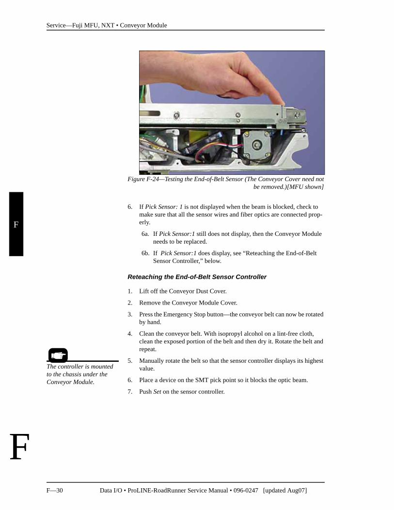
4. Put your finger at the SMT pick point to block the sensor optic.
5. The Control Panel display will show Pick Sensor: 1 whenever your fin-ger is blocking the beam, and Pick Sensor: 0 when not blocked.
For information on rein-stalling the conveyor see page F-27.
Service—Fuji MFU, NXT • Conveyor Module
F—30 Data I/O • ProLINE-RoadRunner Service Manual • 096-0247 [updated Aug07]
F
F
Figure F-24—Testing the End-of-Belt Sensor (The Conveyor Cover need notbe removed.)[MFU shown]
6. If Pick Sensor: 1 is not displayed when the beam is blocked, check to make sure that all the sensor wires and fiber optics are connected prop-erly.
6a. If Pick Sensor:1 still does not display, then the Conveyor Module needs to be replaced.
6b. If Pick Sensor:1 does display, see “Reteaching the End-of-Belt Sensor Controller,” below.
Reteaching the End-of-Belt Sensor Controller
1. Lift off the Conveyor Dust Cover.
2. Remove the Conveyor Module Cover.
3. Press the Emergency Stop button—the conveyor belt can now be rotated by hand.
4. Clean the conveyor belt. With isopropyl alcohol on a lint-free cloth, clean the exposed portion of the belt and then dry it. Rotate the belt and repeat.
5. Manually rotate the belt so that the sensor controller displays its highest value.
6. Place a device on the SMT pick point so it blocks the optic beam.
7. Push Set on the sensor controller.
The controller is mounted to the chassis under the Conveyor Module.
Service—Fuji MFU, NXT • Conveyor Module
Data I/O • ProLINE-RoadRunner Service Manual • 096-0247 [updated Aug07] F—31
F
F
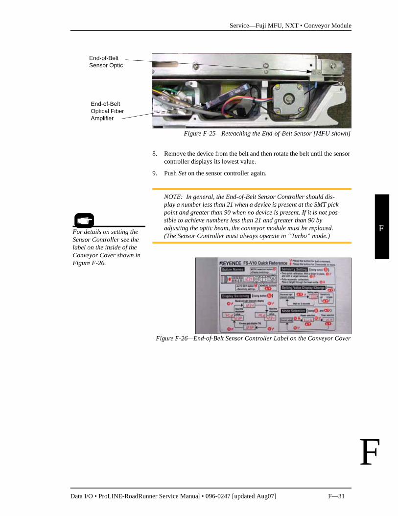
Figure F-25—Reteaching the End-of-Belt Sensor [MFU shown]
8. Remove the device from the belt and then rotate the belt until the sensor controller displays its lowest value.
9. Push Set on the sensor controller again.
NOTE: In general, the End-of-Belt Sensor Controller should dis-play a number less than 21 when a device is present at the SMT pick point and greater than 90 when no device is present. If it is not pos-sible to achieve numbers less than 21 and greater than 90 by adjusting the optic beam, the conveyor module must be replaced. (The Sensor Controller must always operate in “Turbo” mode.)
Figure F-26—End-of-Belt Sensor Controller Label on the Conveyor Cover
End-of-Belt Optical Fiber Amplifier
End-of-Belt Sensor Optic
For details on setting the Sensor Controller see the label on the inside of the Conveyor Cover shown in Figure F-26.
Service—Fuji MFU, NXT • Reject Bin
F—32 Data I/O • ProLINE-RoadRunner Service Manual • 096-0247 [updated Aug07]
F
F
Reject Bin
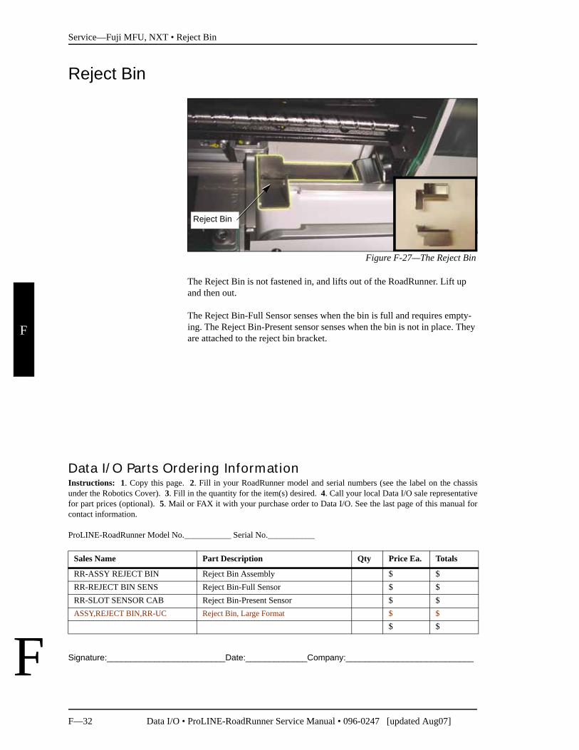
Figure F-27—The Reject Bin
The Reject Bin is not fastened in, and lifts out of the RoadRunner. Lift up and then out.
The Reject Bin-Full Sensor senses when the bin is full and requires empty-ing. The Reject Bin-Present sensor senses when the bin is not in place. They are attached to the reject bin bracket.
Signature:_________________________Date:_____________Company:___________________________
Reject Bin
Data I/O Parts Ordering InformationInstructions: 1. Copy this page. 2. Fill in your RoadRunner model and serial numbers (see the label on the chassisunder the Robotics Cover). 3. Fill in the quantity for the item(s) desired. 4. Call your local Data I/O sale representativefor part prices (optional). 5. Mail or FAX it with your purchase order to Data I/O. See the last page of this manual forcontact information.
ProLINE-RoadRunner Model No.___________ Serial No.___________
Sales Name Part Description Qty Price Ea. Totals
RR-ASSY REJECT BIN Reject Bin Assembly $ $RR-REJECT BIN SENS Reject Bin-Full Sensor $ $RR-SLOT SENSOR CAB Reject Bin-Present Sensor $ $ASSY,REJECT BIN,RR-UC Reject Bin, Large Format $ $
$ $
Service—Fuji MFU, NXT • Reject Bin
Data I/O • ProLINE-RoadRunner Service Manual • 096-0247 [updated Aug07] F—33
F
F
Removing the Reject Bin Sensors
1. Turn the power off.
2. Disconnect the power cord and air supply.
3. Lift off the Robotics Cover.
4. Push the head away from the programmer.
5. Remove the Lower Cover.
6. Remove the Conveyor Module screws (the wires do not need to be unplugged) and lift it out of the way.
7. Lift out the Reject Bin.
8. Unplug the sensor wire connectors J1C and J1C2 from the Interconnect Panel. Cut wire ties as necessary.
9. Remove three socket head screws securing the Reject Bin Bracket to the chassis and lift it out.
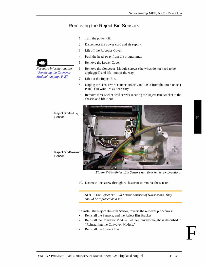
Figure F-28—Reject Bin Sensors and Bracket Screw Locations.
10. Unscrew one screw through each sensor to remove the sensor.
NOTE: The Reject Bin-Full Sensor consists of two sensors. They should be replaced as a set.
To install the Reject Bin-Full Sensor, reverse the removal procedures:• Reinstall the Sensors, and the Reject Bin Bracket• Reinstall the Conveyor Module. Set the Conveyor height as described in
“Reinstalling the Conveyor Module.”• Reinstall the Lower Cover.
For more information, see “Removing the Conveyor Module” on page F-27.
Reject Bin-Full Sensor
Reject Bin-Present Sensor
Service—Fuji MFU, NXT • Control Panel Module
F—34 Data I/O • ProLINE-RoadRunner Service Manual • 096-0247 [updated Aug07]
F
F
Control Panel Module
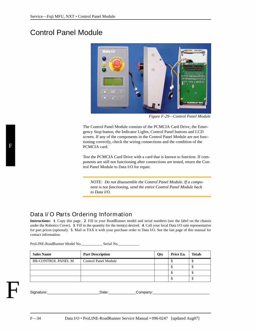
Figure F-29—Control Panel Module
The Control Panel Module consists of the PCMCIA Card Drive, the Emer-gency Stop button, the Indicator Lights, Control Panel buttons and LCD screen. If any of the components in the Control Panel Module are not func-tioning correctly, check the wiring connections and the condition of the PCMCIA card.
Test the PCMCIA Card Drive with a card that is known to function. If com-ponents are still not functioning after connections are tested, return the Con-trol Panel Module to Data I/O for repair.
NOTE: Do not disassemble the Control Panel Module. If a compo-nent is not functioning, send the entire Control Panel Module back to Data I/O.
Signature:_________________________Date:_____________Company:___________________________
Data I/O Parts Ordering InformationInstructions: 1. Copy this page. 2. Fill in your RoadRunner model and serial numbers (see the label on the chassisunder the Robotics Cover). 3. Fill in the quantity for the item(s) desired. 4. Call your local Data I/O sale representativefor part prices (optional). 5. Mail or FAX it with your purchase order to Data I/O. See the last page of this manual forcontact information.
ProLINE-RoadRunner Model No.___________ Serial No.___________
Sales Name Part Description Qty Price Ea. Totals
RR-CONTROL PANEL M Control Panel Module $ $$ $$ $$ $
Service—Fuji MFU, NXT • Control Panel Module
Data I/O • ProLINE-RoadRunner Service Manual • 096-0247 [updated Aug07] F—35
F
F
Removing the Control Panel Module
1. Pause the RoadRunner.
2. Remove the PCMCIA card when the blue light is on.
3. Turn the power off.
4. Disconnect the RoadRunner power cord and air supply.
5. Remove the Robotics Cover.
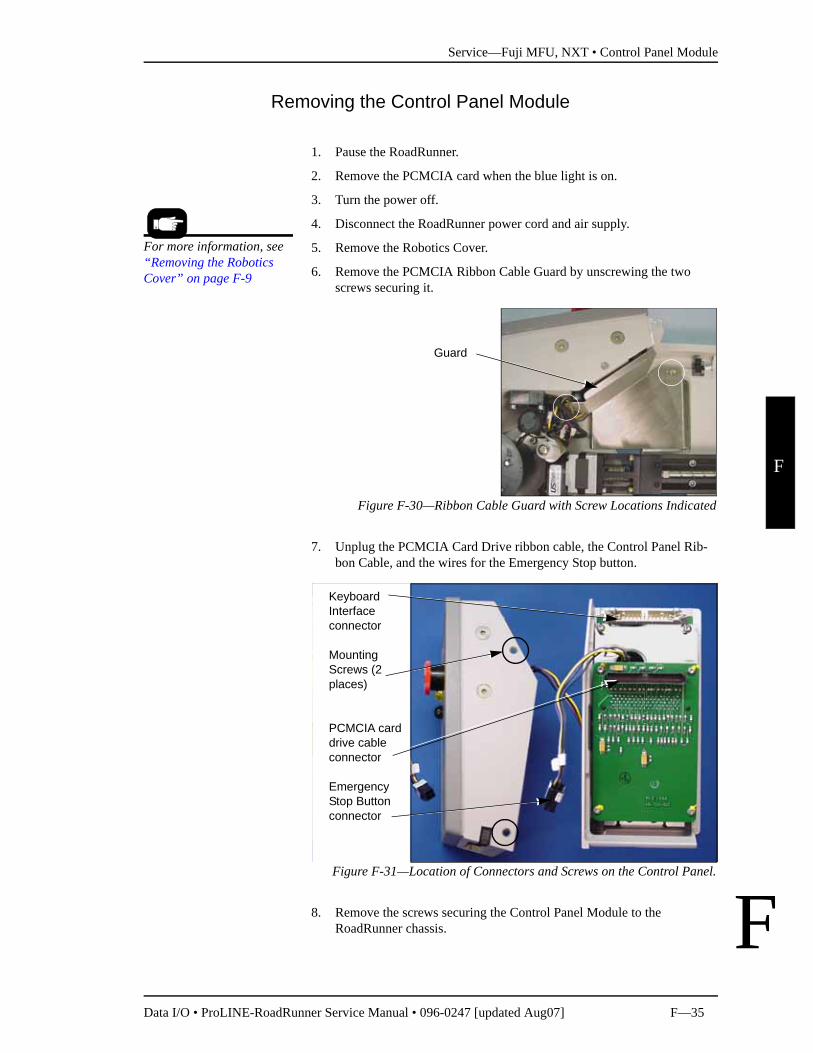
6. Remove the PCMCIA Ribbon Cable Guard by unscrewing the two screws securing it.
Figure F-30—Ribbon Cable Guard with Screw Locations Indicated
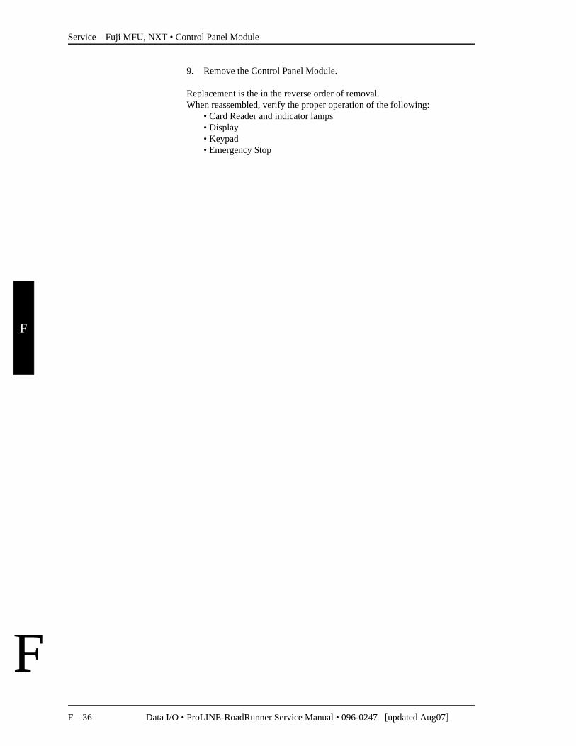
7. Unplug the PCMCIA Card Drive ribbon cable, the Control Panel Rib-bon Cable, and the wires for the Emergency Stop button.
Figure F-31—Location of Connectors and Screws on the Control Panel.
8. Remove the screws securing the Control Panel Module to the RoadRunner chassis.
For more information, see “Removing the Robotics Cover” on page F-9
Guard
Keyboard Interface connector
Mounting Screws (2 places)
PCMCIA card drive cable connector
Emergency Stop Button connector
Service—Fuji MFU, NXT • Control Panel Module
F—36 Data I/O • ProLINE-RoadRunner Service Manual • 096-0247 [updated Aug07]
F
F
9. Remove the Control Panel Module.
Replacement is the in the reverse order of removal.When reassembled, verify the proper operation of the following:
• Card Reader and indicator lamps• Display• Keypad• Emergency Stop
Service—Fuji MFU, NXT • Pick and Place Head
Data I/O • ProLINE-RoadRunner Service Manual • 096-0247 [updated Aug07] F—37
F
F
Pick and Place HeadThe head assembly contains four probes (most models), each with Vacuum Tips and Vacuum Chamber Blocks. Some parts can be replaced and some probe functions can be adjusted.
Aligning the PNP Head
Since device placement tolerance is small, the PNP head may need aligning when a module is replaced or repaired. The head may also need aligning if any of the following error messages are displayed:• Device pick failure at input, with probe n.• Device pick failure on probe n.• Device dropped from head n.For head alignment procedures see “Setting the Tape Parameter” and “Set-ting the Skt 1 Parameter” in Chapter 3 of the Owner's Manual.
Adjusting and Balancing Probe Lowering Speed
If the probe lowering speed is too fast, devices in the carrier tape becomes unstable as a probe strikes a device during the pick routine. If the probe speed is too slow, throughput will suffer and device placement problems may occur.
Adjust the probe speed with power and pressurized air on. Ensure that vac-uum to all probes is disabled before starting this procedure. The easiest way to ensure this is to cycle the power.
1. Load and align the device tape without peeling off the cover tape. (The Cover Tape Peel Bar and Spool will not be used.)
2. Scroll to and select Robot Diagnostics.
3. Scroll to and select Probe 1.
4. Scroll to and select Speed. The probe will move to the device pick point and cycle continuously.
5. Read the speed that is now displayed in the screen.The speed should be 135±5.
If it needs adjustment skip to step 8.If it does not need adjustment:
For more information . . . See “Loading Device Tape” and “Aligning the Device Tape” in Chapter 3 of the Owner’s Manual. Pinch point: Moving mechanical parts. Keep hands
away from moving parts. The following procedures require the Robotics Cover to be removed while
mechanical parts are in motion. Use caution.
WARNING!
Service—Fuji MFU, NXT • Pick and Place Head
F—38 Data I/O • ProLINE-RoadRunner Service Manual • 096-0247 [updated Aug07]
F
F
5a. Press Menu.
5b. Scroll to and select the next probe.
5c. Repeat steps 4 and on.
6. Remove the Lower Cover and the Conveyor Module Cover.
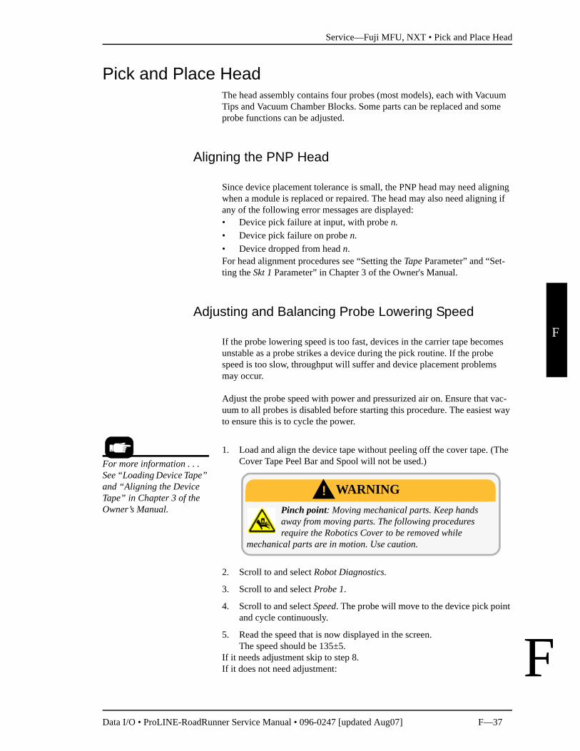
7. Loosen the locknut ring on the Probe Speed Flow Control for Probe 1 (or current probe) on the Interface Manifold.
The Interface Manifold is mounted on the chassis below, and to the right of, the Reject Bin.
Figure F-32—Interface Manifold with Probe lowering Flow Controlsinstalled. Also see Figure F-33 on page F-39.
8. Adjust the Probe Speed flow control for Probe 1 (or current probe) while watching the speed displayed at the keypad screen.
9. When the speed is within the proper range, press Menu—probe motion will stop.
10. Tighten the locknut ring on the Flow Control.
11. Recheck the speed. If it is outside the proper range then readjust.
12. Scroll to and select the next Probe.
13. Repeat steps 4 and on for the next probe.
14. When finished, see Adjusting Probe Raising Speed (some models) or replace both covers and remove the device tape.
Adjusting Probe Raising Speed
NOTE: Probe lowering speed should be set first. See “Adjusting and Balancing Probe Lowering Speed” on page F-37.
Flow Control adjustment stem for Probe 1
For more information see “Covers” on page F-8.
Service—Fuji MFU, NXT • Pick and Place Head
Data I/O • ProLINE-RoadRunner Service Manual • 096-0247 [updated Aug07] F—39
F
F
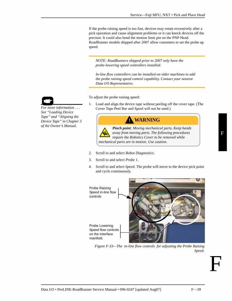
If the probe raising speed is too fast, devices may rotate excessively after a pick operation and cause alignment problems or it can knock devices off the precisor. It could also bend the motion limit pin on the PNP Head. RoadRunner models shipped after 2007 allow customers to set the probe up speed.
NOTE: RoadRunners shipped prior to 2007 only have the probe-lowering speed controllers installed.
In-line flow controllers can be installed on older machines to add the probe raising speed control capability. Contact your nearest Data I/O Representative.
To adjust the probe raising speed:
1. Load and align the device tape without peeling off the cover tape. (The Cover Tape Peel Bar and Spool will not be used.)
2. Scroll to and select Robot Diagnostics.
3. Scroll to and select Probe 1.
4. Scroll to and select Speed. The probe will move to the device pick point and cycle continuously.
Figure F-33—The in-line flow controls for adjusting the Probe RaisingSpeed.
Pinch point: Moving mechanical parts. Keep hands away from moving parts. The following procedures require the Robotics Cover to be removed while
mechanical parts are in motion. Use caution.
WARNING!
Probe Raising Speed in-line flow controls
Probe Lowering Speed flow controls on the Interface manifold.
For more information . . . See “Loading Device Tape” and “Aligning the Device Tape” in Chapter 3 of the Owner’s Manual.
Service—Fuji MFU, NXT • Pick and Place Head
F—40 Data I/O • ProLINE-RoadRunner Service Manual • 096-0247 [updated Aug07]
F
F
5. Use the Up Arrow and Down Arrow on the RoadRunner Control Panel to move the probe up and down. Watch the probe to observe the probe raising speed.
6. If the probe raising speed looks faster or slower than the lowering speed, remove the Lower Cover and the Conveyor Module Cover.
7. Manually adjust the speed by hand using the knob on the in-line flow controller. Adjust the probe raising speed until it closely matches the probe lowering speed (based on your visual observation).
8. Press Menu to deselect the current probe.
9. Scroll to and select the next probe.
10. Repeat these steps (from step 4 and on) for each probe.
11. When finished, replace both covers and remove the device tape.
For more information see “Covers” on page F-8.
Service—Fuji MFU, NXT • Pick and Place Head
Data I/O • ProLINE-RoadRunner Service Manual • 096-0247 [updated Aug07] F—41
F
F
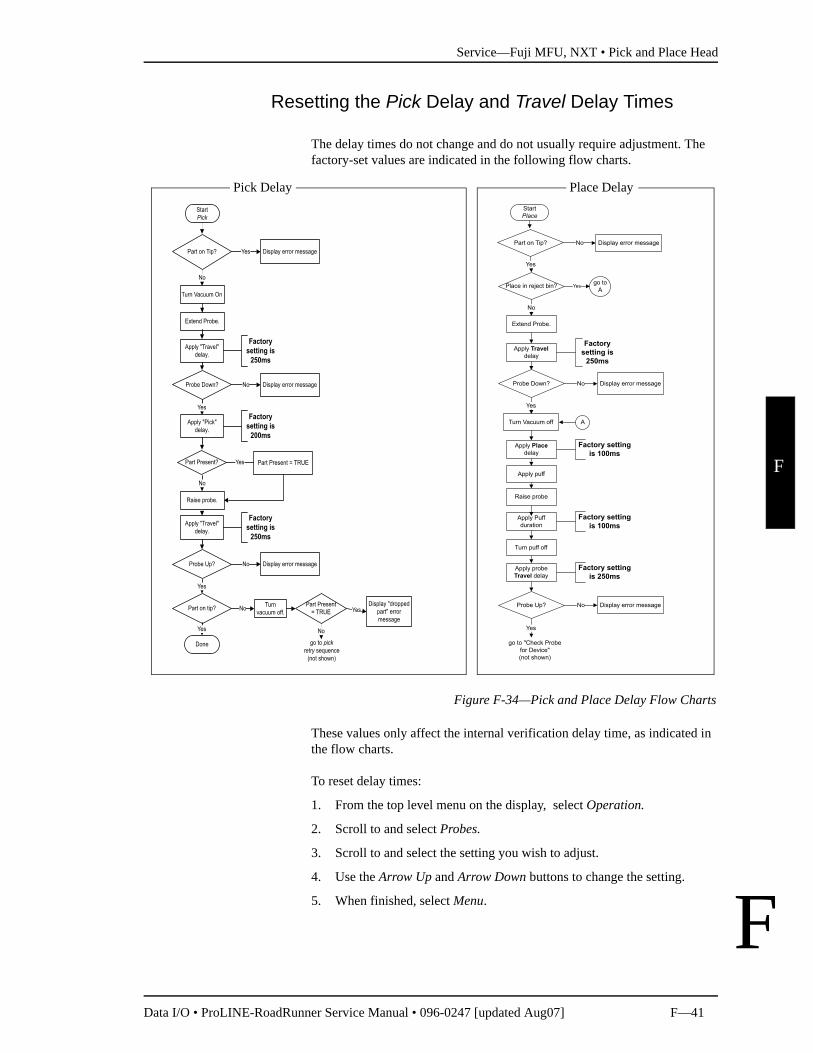
Resetting the Pick Delay and Travel Delay Times
The delay times do not change and do not usually require adjustment. The factory-set values are indicated in the following flow charts.
Figure F-34—Pick and Place Delay Flow Charts
These values only affect the internal verification delay time, as indicated in the flow charts.
To reset delay times:
1. From the top level menu on the display, select Operation.
2. Scroll to and select Probes.
3. Scroll to and select the setting you wish to adjust.
4. Use the Arrow Up and Arrow Down buttons to change the setting.
5. When finished, select Menu.
Pick Delay Place Delay
Service—Fuji MFU, NXT • Pick and Place Head
F—42 Data I/O • ProLINE-RoadRunner Service Manual • 096-0247 [updated Aug07]
F
F
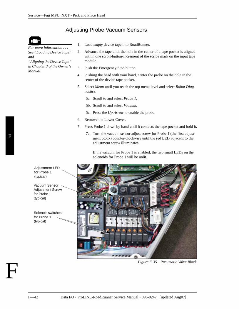
Adjusting Probe Vacuum Sensors
1. Load empty device tape into RoadRunner.
2. Advance the tape until the hole in the center of a tape pocket is aligned within one scroll-button-increment of the scribe mark on the input tape module.
3. Push the Emergency Stop button.
4. Pushing the head with your hand, center the probe on the hole in the center of the device tape pocket.
5. Select Menu until you reach the top menu level and select Robot Diag-nostics.
5a. Scroll to and select Probe 1.
5b. Scroll to and select Vacuum.
5c. Press the Up Arrow to enable the probe.
6. Remove the Lower Cover.
7. Press Probe 1 down by hand until it contacts the tape pocket and hold it.
7a. Turn the vacuum sensor adjust screw for Probe 1 (the first adjust-ment block) counter-clockwise until the red LED adjacent to the adjustment screw illuminates.
If the vacuum for Probe 1 is enabled, the two small LEDs on the solenoids for Probe 1 will be unlit.
Figure F-35—Pneumatic Valve Block
For more information . . . See “Loading Device Tape” and“Aligning the Device Tape” in Chapter 3 of the Owner's Manual.
Solenoid switches for Probe 1(typical)
Vacuum Sensor Adjustment Screw for Probe 1(typical)
Adjustment LED for Probe 1(typical)
Service—Fuji MFU, NXT • Pick and Place Head
Data I/O • ProLINE-RoadRunner Service Manual • 096-0247 [updated Aug07] F—43
F
F
7b. Turn the vacuum sensor adjust screw for Probe 1 clockwise until the red LED goes out. Continue turning the screw 1 revolution clockwise. Release the probe allowing it to resume the up position.
8. Select Menu until you reach the top menu level again and select Robot Diagnostics.
8a. Scroll to and select Probe 1.
8b. Scroll to and select Vacuum.
8c. Press the Down Arrow to disable the probe.
9. Manually position probes 2, 3 and 4 over the hole in the tape pocket and repeat steps 5 through 7 for each.
10. Re-install the Lower Cover when finished.
Service—Fuji MFU, NXT • Pick and Place Head
F—44 Data I/O • ProLINE-RoadRunner Service Manual • 096-0247 [updated Aug07]
F
F
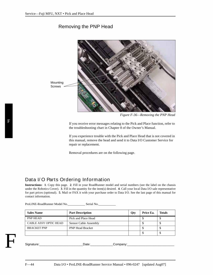
Removing the PNP Head
Figure F-36—Removing the PNP Head
If you receive error messages relating to the Pick and Place function, refer to the troubleshooting chart in Chapter 8 of the Owner’s Manual.
If you experience trouble with the Pick and Place Head that is not covered in this manual, remove the head and send it to Data I/O Customer Service for repair or replacement.
Removal procedures are on the following page.
Signature:_________________________Date:_____________Company:___________________________
Mounting Screws
Data I/O Parts Ordering InformationInstructions: 1. Copy this page. 2. Fill in your RoadRunner model and serial numbers (see the label on the chassisunder the Robotics Cover). 3. Fill in the quantity for the item(s) desired. 4. Call your local Data I/O sale representativefor part prices (optional). 5. Mail or FAX it with your purchase order to Data I/O. See the last page of this manual forcontact information.
ProLINE-RoadRunner Model No.___________ Serial No.___________
Sales Name Part Description Qty Price Ea. Totals
PNP HEAD Pick and Place Head $ $CABLE ASSY OPTIC HEAD Sensor Cable Assembly $ $BRACKET PNP PNP Head Bracket $ $
$ $
Service—Fuji MFU, NXT • Pick and Place Head
Data I/O • ProLINE-RoadRunner Service Manual • 096-0247 [updated Aug07] F—45
F
F
To remove the Pick and Place Head:
1. Turn the power off.
2. Disconnect the RoadRunner power cord and air supply.
3. Remove the Robotics Cover.
4. Remove the PNP Head Cover.
5. Disconnect the tube from the top of each probe.
6. Remove two socket head cap screws attaching the head to the ball screw carriage.
7. Lightly pull the head a couple of centimeters away from the carriage.
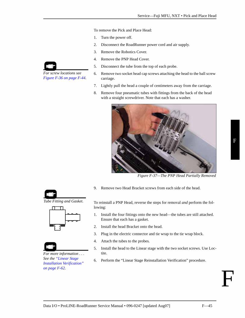
8. Remove four pneumatic tubes with fittings from the back of the head with a straight screwdriver. Note that each has a washer.
Figure F-37—The PNP Head Partially Removed
9. Remove two Head Bracket screws from each side of the head.
To reinstall a PNP Head, reverse the steps for removal and perform the fol-lowing:
1. Install the four fittings onto the new head—the tubes are still attached. Ensure that each has a gasket.
2. Install the head Bracket onto the head.
3. Plug in the electric connector and tie wrap to the tie wrap block.
4. Attach the tubes to the probes.
5. Install the head to the Linear stage with the two socket screws. Use Loc-tite.
6. Perform the “Linear Stage Reinstallation Verification” procedure.
For screw locations see Figure F-36 on page F-44.
Tube Fitting and Gasket.
For more information . . . See the “Linear Stage Installation Verification” on page F-62.
Service—Fuji MFU, NXT • Programmer Module
F—46 Data I/O • ProLINE-RoadRunner Service Manual • 096-0247 [updated Aug07]
F
F
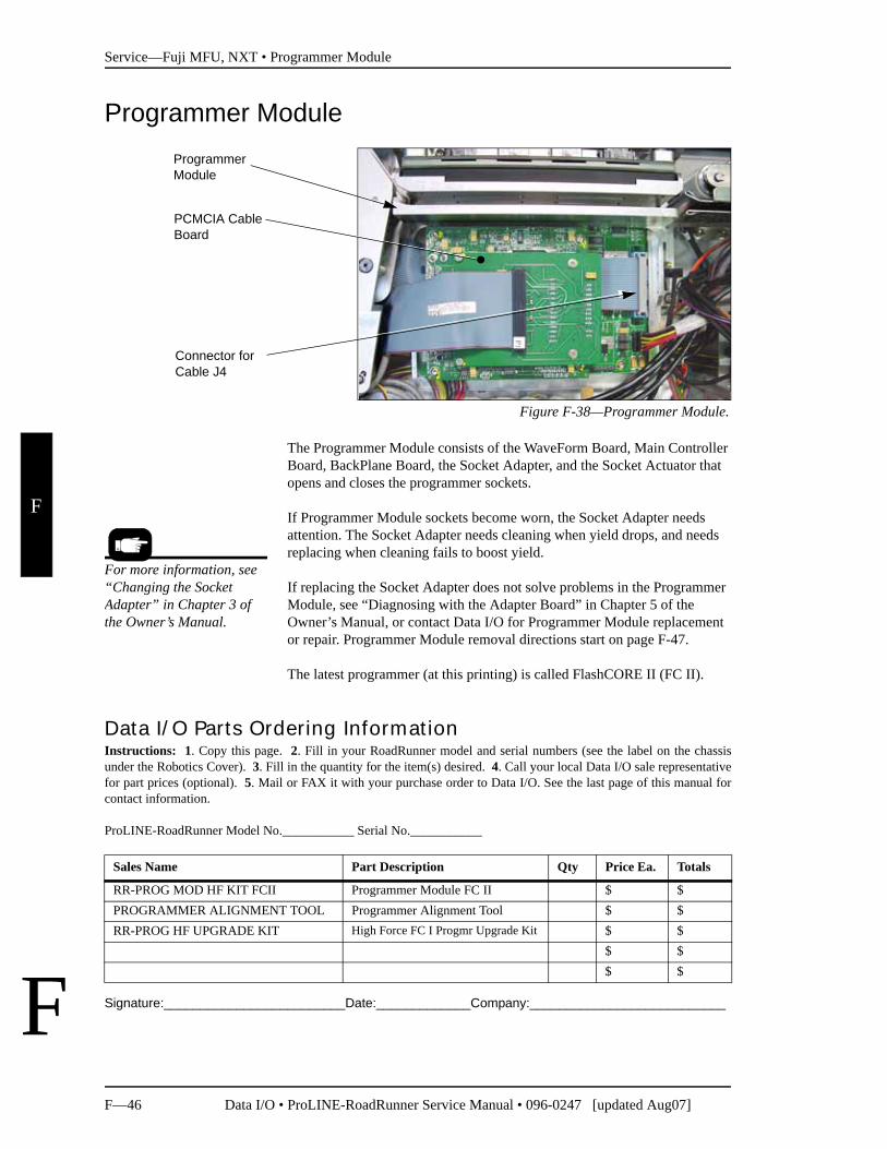
Programmer Module
Figure F-38—Programmer Module.
The Programmer Module consists of the WaveForm Board, Main Controller Board, BackPlane Board, the Socket Adapter, and the Socket Actuator that opens and closes the programmer sockets.
If Programmer Module sockets become worn, the Socket Adapter needs attention. The Socket Adapter needs cleaning when yield drops, and needs replacing when cleaning fails to boost yield.
If replacing the Socket Adapter does not solve problems in the Programmer Module, see “Diagnosing with the Adapter Board” in Chapter 5 of the Owner’s Manual, or contact Data I/O for Programmer Module replacement or repair. Programmer Module removal directions start on page F-47.
The latest programmer (at this printing) is called FlashCORE II (FC II).
Signature:_________________________Date:_____________Company:___________________________
Programmer Module
Connector for Cable J4
PCMCIA Cable Board
For more information, see “Changing the Socket Adapter” in Chapter 3 of the Owner’s Manual.
Data I/O Parts Ordering InformationInstructions: 1. Copy this page. 2. Fill in your RoadRunner model and serial numbers (see the label on the chassisunder the Robotics Cover). 3. Fill in the quantity for the item(s) desired. 4. Call your local Data I/O sale representativefor part prices (optional). 5. Mail or FAX it with your purchase order to Data I/O. See the last page of this manual forcontact information.
ProLINE-RoadRunner Model No.___________ Serial No.___________
Sales Name Part Description Qty Price Ea. Totals
RR-PROG MOD HF KIT FCII Programmer Module FC II $ $PROGRAMMER ALIGNMENT TOOL Programmer Alignment Tool $ $RR-PROG HF UPGRADE KIT High Force FC I Progmr Upgrade Kit $ $
$ $$ $
Service—Fuji MFU, NXT • Programmer Module
Data I/O • ProLINE-RoadRunner Service Manual • 096-0247 [updated Aug07] F—47
F
F
Removing the Programmer Module
NOTE: Only technicians who have taken the ProLINE-RoadRunner Service training course should attempt to remove the Programmer Module. It is an involved process.
A special alignment tool is required from Data I/O to reinstall the Programmer Module.
1. Switch the power off.
2. Disconnect the RoadRunner power cord and air supply.
3. Lift off the Robotics Cover.
4. Push the head away from the programmer.
5. Remove the Lower Cover.
6. Remove the Actuator Plate by sliding it out of the bracket.
7. Optional: Remove the Socket Adapter.
8. Remove the Conveyor Module Cover.
9. Lift out the Reject Bin.
10. Remove screws from the Conveyor Module and set it aside—wires are still attached.
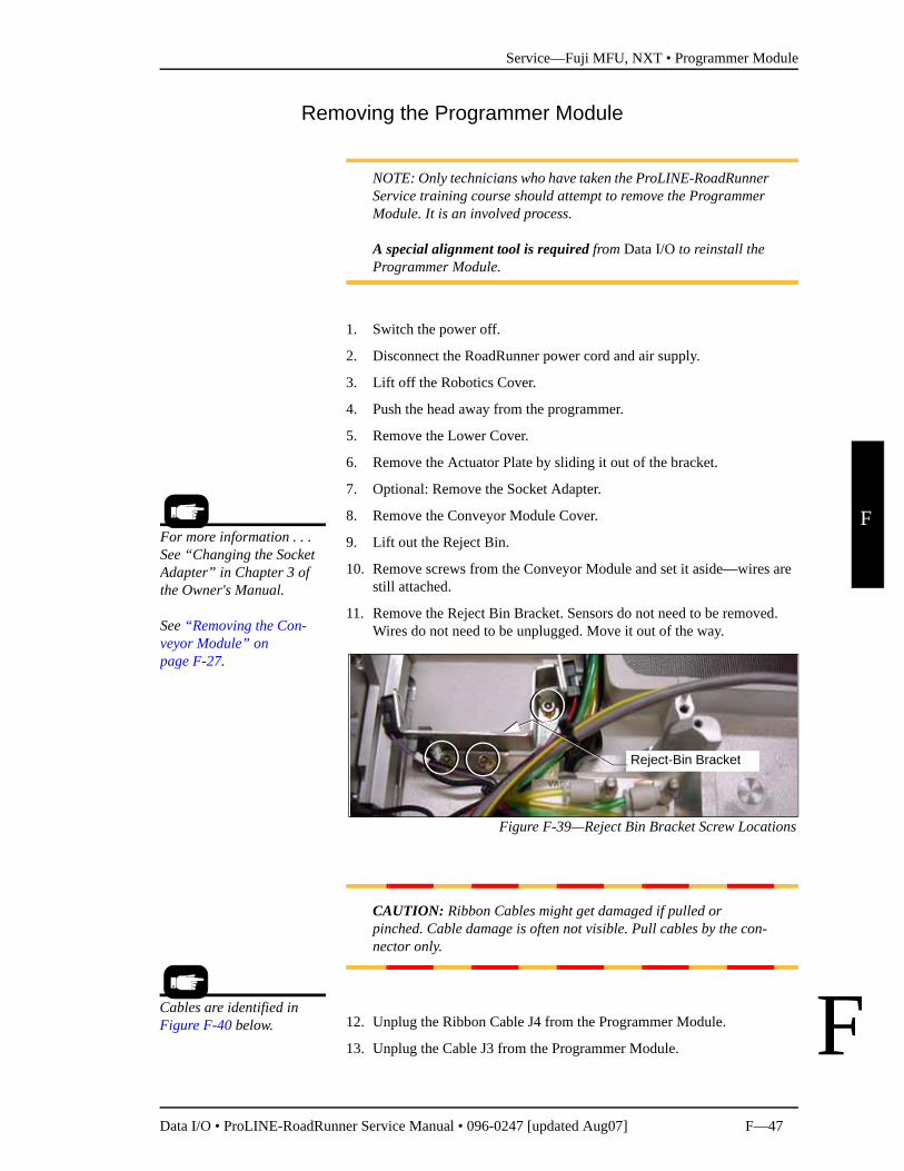
11. Remove the Reject Bin Bracket. Sensors do not need to be removed. Wires do not need to be unplugged. Move it out of the way.
Figure F-39—Reject Bin Bracket Screw Locations
CAUTION: Ribbon Cables might get damaged if pulled or pinched. Cable damage is often not visible. Pull cables by the con-nector only.
12. Unplug the Ribbon Cable J4 from the Programmer Module.
13. Unplug the Cable J3 from the Programmer Module.
For more information . . . See “Changing the Socket Adapter” in Chapter 3 of the Owner's Manual.
See “Removing the Con-veyor Module” on page F-27.
Reject-Bin Bracket
Cables are identified in Figure F-40 below.
Service—Fuji MFU, NXT • Programmer Module
F—48 Data I/O • ProLINE-RoadRunner Service Manual • 096-0247 [updated Aug07]
F
F
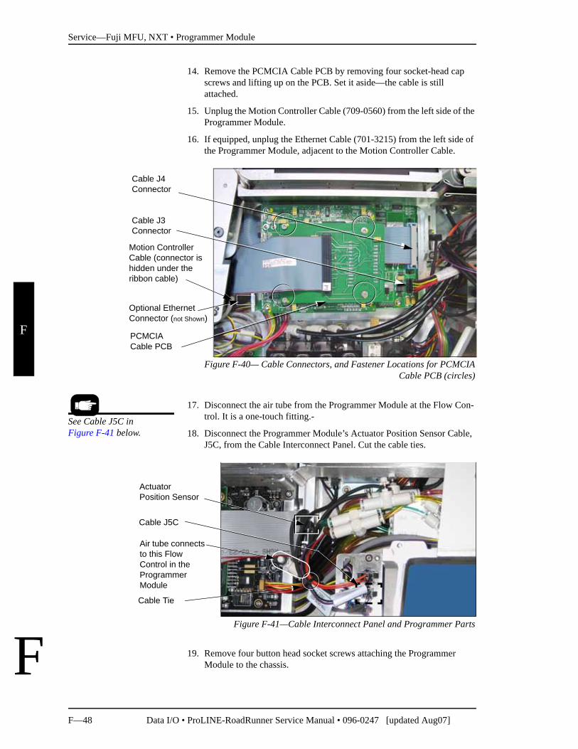
14. Remove the PCMCIA Cable PCB by removing four socket-head cap screws and lifting up on the PCB. Set it aside—the cable is still attached.
15. Unplug the Motion Controller Cable (709-0560) from the left side of the Programmer Module.
16. If equipped, unplug the Ethernet Cable (701-3215) from the left side of the Programmer Module, adjacent to the Motion Controller Cable.
Figure F-40— Cable Connectors, and Fastener Locations for PCMCIACable PCB (circles)
17. Disconnect the air tube from the Programmer Module at the Flow Con-trol. It is a one-touch fitting.-
18. Disconnect the Programmer Module’s Actuator Position Sensor Cable, J5C, from the Cable Interconnect Panel. Cut the cable ties.
Figure F-41—Cable Interconnect Panel and Programmer Parts
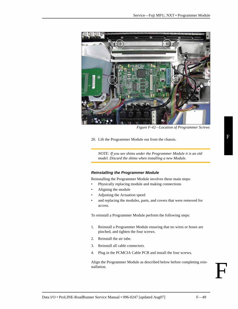
19. Remove four button head socket screws attaching the Programmer Module to the chassis.
Cable J4 Connector
Cable J3 Connector
PCMCIA Cable PCB
Motion Controller Cable (connector is hidden under the ribbon cable)
Optional Ethernet Connector (not Shown)
See Cable J5C in Figure F-41 below.
Cable Tie
Cable J5C
Air tube connects to this Flow Control in the Programmer Module
Actuator Position Sensor
Service—Fuji MFU, NXT • Programmer Module
Data I/O • ProLINE-RoadRunner Service Manual • 096-0247 [updated Aug07] F—49
F
F
Figure F-42—Location of Programmer Screws
20. Lift the Programmer Module out from the chassis.
NOTE: If you see shims under the Programmer Module it is an old model. Discard the shims when installing a new Module.
Reinstalling the Programmer ModuleReinstalling the Programmer Module involves these main steps:• Physically replacing module and making connections• Aligning the module• Adjusting the Actuation speed• and replacing the modules, parts, and covers that were removed for
access.
To reinstall a Programmer Module perform the following steps:
1. Reinstall a Programmer Module ensuring that no wires or hoses are pinched, and tighten the four screws.
2. Reinstall the air tube.
3. Reinstall all cable connectors.
4. Plug in the PCMCIA Cable PCB and install the four screws.
Align the Programmer Module as described below before completing rein-stallation.
Service—Fuji MFU, NXT • Programmer Module
F—50 Data I/O • ProLINE-RoadRunner Service Manual • 096-0247 [updated Aug07]
F
F
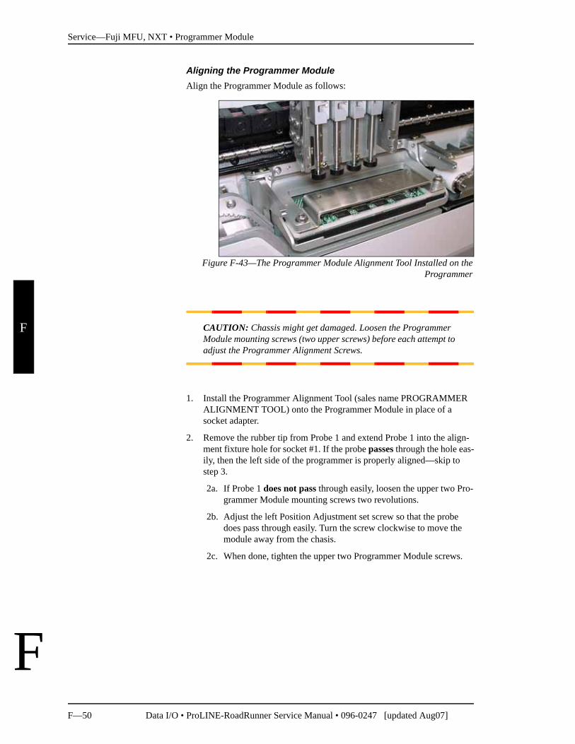
Aligning the Programmer ModuleAlign the Programmer Module as follows:
Figure F-43—The Programmer Module Alignment Tool Installed on theProgrammer
CAUTION: Chassis might get damaged. Loosen the Programmer Module mounting screws (two upper screws) before each attempt to adjust the Programmer Alignment Screws.
1. Install the Programmer Alignment Tool (sales name PROGRAMMER ALIGNMENT TOOL) onto the Programmer Module in place of a socket adapter.
2. Remove the rubber tip from Probe 1 and extend Probe 1 into the align-ment fixture hole for socket #1. If the probe passes through the hole eas-ily, then the left side of the programmer is properly aligned—skip to step 3.
2a. If Probe 1 does not pass through easily, loosen the upper two Pro-grammer Module mounting screws two revolutions.
2b. Adjust the left Position Adjustment set screw so that the probe does pass through easily. Turn the screw clockwise to move the module away from the chasis.
2c. When done, tighten the upper two Programmer Module screws.
Service—Fuji MFU, NXT • Programmer Module
Data I/O • ProLINE-RoadRunner Service Manual • 096-0247 [updated Aug07] F—51
F
F
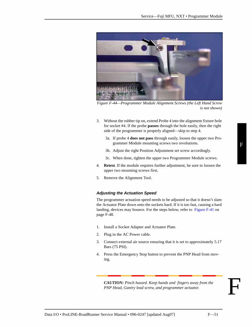
Figure F-44—Programmer Module Alignment Screws (the Left Hand Screwis not shown)
3. Without the rubber tip on, extend Probe 4 into the alignment fixture hole for socket #4. If the probe passes through the hole easily, then the right side of the programmer is properly aligned—skip to step 4.
3a. If probe 4 does not pass through easily, loosen the upper two Pro-grammer Module mounting screws two revolutions.
3b. Adjust the right Position Adjustment set screw accordingly.
3c. When done, tighten the upper two Programmer Module screws.
4. Retest. If the module requires further adjustment, be sure to loosen the upper two mounting screws first.
5. Remove the Alignment Tool.
Adjusting the Actuation SpeedThe programmer actuation speed needs to be adjusted so that it doesn’t slam the Actuator Plate down onto the sockets hard. If it is too fast, causing a hard landing, devices may bounce. For the steps below, refer to Figure F-41 on page F-48.
1. Install a Socket Adapter and Actuator Plate.
2. Plug in the AC Power cable.
3. Connect external air source ensuring that it is set to approximately 5.17 Bars (75 PSI).
4. Press the Emergency Stop button to prevent the PNP Head from mov-ing.
CAUTION: Pinch hazard. Keep hands and fingers away from the PNP Head, Gantry lead screw, and programmer actuator.
Service—Fuji MFU, NXT • Programmer Module
F—52 Data I/O • ProLINE-RoadRunner Service Manual • 096-0247 [updated Aug07]
F
F
The E-Stop does not stop the programmer from actuating—opening and closing the sockets.
CAUTION: Shock hazard. The E-Stop does not stop electrical flow to internal electronics.
5. Insert a job card with Supervisor authority and switch the power on.
NOTE: Your RoadRunner may have a flow control that can be adjusted by hand or it may require a straight screwdriver.
6. Locate the Programmer Flow Control and adjust it counter-clockwise to full open, then turn it clockwise 2-1/2 revolutions.
7. At the Control Panel, press Menu. Then scroll to and select Robot Diagnostics > Socket > State. After selecting the State command a dot, or bullet, appears next to it. Then the Down Arrow and Up Arrow buttons will actuate the programmer.
8. Actuate the programmer and watch the speed. Adjust the Flow Control and retry if the actuator appears to hit the sockets too hard. Use the Flow Control to soften the impact. However, too slow will cause timing prob-lems as well as reduce throughput.
Complete the Programmer Module installation by installing the Reject Bin Bracket, the Conveyor Module, the Reject Bin, and the Lower Cover.

Service—Fuji MFU, NXT • Programmer Module
Data I/O • ProLINE-RoadRunner Service Manual • 096-0247 [updated Aug07] F—53
F
F
blank page
Service—Fuji MFU, NXT • NVRAM Battery
F—54 Data I/O • ProLINE-RoadRunner Service Manual • 096-0247 [updated Aug07]
F
F
NVRAM Battery
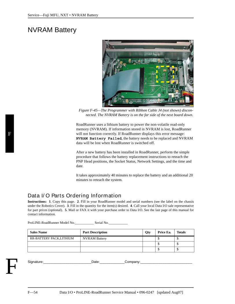
Figure F-45—The Programmer with Ribbon Cable J4 (not shown) discon-nected. The NVRAM Battery is on the far side of the next board down.
RoadRunner uses a lithium battery to power the non-volatile read-only memory (NVRAM). If information stored in NVRAM is lost, RoadRunner will not function correctly. If RoadRunner displays this error message: NVRAM Battery Failed, the battery needs to be replaced and NVRAM data will be lost when RoadRunner is switched off.
After a new battery has been installed in RoadRunner, perform the simple procedure that follows the battery replacement instructions to reteach the PNP Head positions, the Socket Status, Network Settings, and the time and date.
It takes approximately 40 minutes to replace the battery and an additional 20 minutes to reteach the system.
Signature:_________________________Date:_____________Company:___________________________
Data I/O Parts Ordering InformationInstructions: 1. Copy this page. 2. Fill in your RoadRunner model and serial numbers (see the label on the chassisunder the Robotics Cover). 3. Fill in the quantity for the item(s) desired. 4. Call your local Data I/O sale representativefor part prices (optional). 5. Mail or FAX it with your purchase order to Data I/O. See the last page of this manual forcontact information.
ProLINE-RoadRunner Model No.___________ Serial No.___________
Sales Name Part Description Qty Price Ea. Totals
RR-BATTERY PACK,LITHIUM NVRAM Battery $ $$ $$ $
Service—Fuji MFU, NXT • NVRAM Battery
Data I/O • ProLINE-RoadRunner Service Manual • 096-0247 [updated Aug07] F—55
F
F
Removing the NVRAM Battery
The battery is an integral part of the PowerCap Module. The entire PowerCap cap must be replaced. The PowerCap Module is located on the back side of the RPX_LITE circuit board.
1. Switch the RoadRunner power off.
2. Disconnect RoadRunner power cord and air supply.
3. Lift off the Robotics Cover.
4. Remove the Lower Cover.
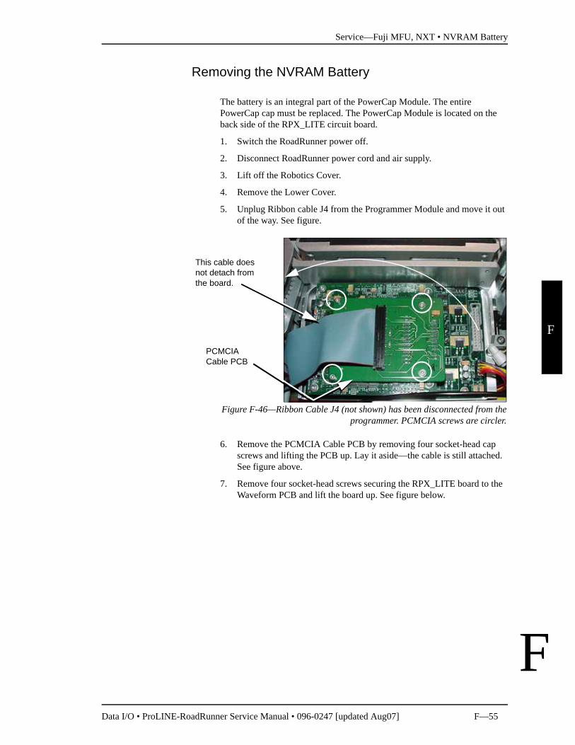
5. Unplug Ribbon cable J4 from the Programmer Module and move it out of the way. See figure.
Figure F-46—Ribbon Cable J4 (not shown) has been disconnected from theprogrammer. PCMCIA screws are circler.
6. Remove the PCMCIA Cable PCB by removing four socket-head cap screws and lifting the PCB up. Lay it aside—the cable is still attached. See figure above.
7. Remove four socket-head screws securing the RPX_LITE board to the Waveform PCB and lift the board up. See figure below.
PCMCIA Cable PCB
This cable does not detach from the board.
Service—Fuji MFU, NXT • NVRAM Battery
F—56 Data I/O • ProLINE-RoadRunner Service Manual • 096-0247 [updated Aug07]
F
F
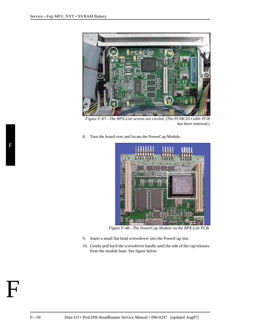
Figure F-47—The RPX-Lite screws are circled. (The PCMCIA Cable PCBhas been removed.)
8. Turn the board over and locate the PowerCap Module.
Figure F-48—The PowerCap Module on the RPX-Lite PCB.
9. Insert a small flat head screwdriver into the PowerCap slot.
10. Gently pull back the screwdriver handle until the side of the cap releases from the module base. See figure below.
Service—Fuji MFU, NXT • NVRAM Battery
Data I/O • ProLINE-RoadRunner Service Manual • 096-0247 [updated Aug07] F—57
F
F
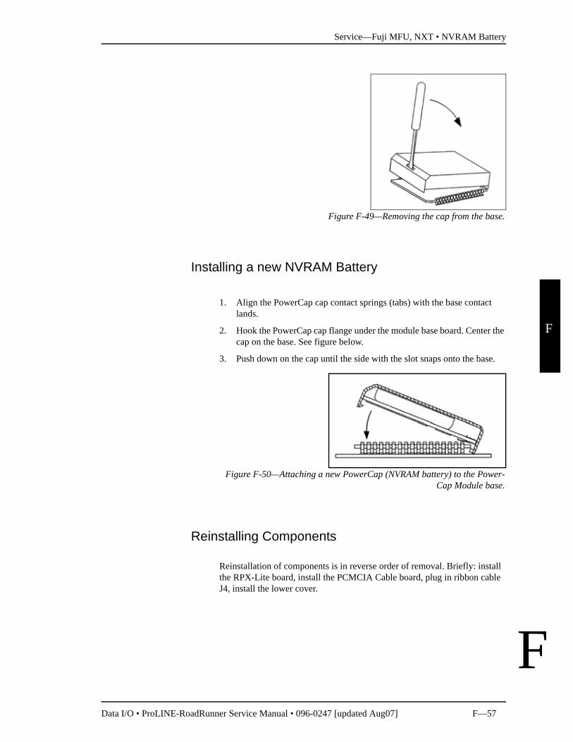
Figure F-49—Removing the cap from the base.
Installing a new NVRAM Battery
1. Align the PowerCap cap contact springs (tabs) with the base contact lands.
2. Hook the PowerCap cap flange under the module base board. Center the cap on the base. See figure below.
3. Push down on the cap until the side with the slot snaps onto the base.
Figure F-50—Attaching a new PowerCap (NVRAM battery) to the Power-Cap Module base.
Reinstalling Components
Reinstallation of components is in reverse order of removal. Briefly: install the RPX-Lite board, install the PCMCIA Cable board, plug in ribbon cable J4, install the lower cover.
Service—Fuji MFU, NXT • NVRAM Battery
F—58 Data I/O • ProLINE-RoadRunner Service Manual • 096-0247 [updated Aug07]
F
F
Reteaching the NVRAM
After a new battery has been installed in RoadRunner, you need to teach it the PNP Head positions, the Socket Status, Network Settings, and the time and date so that they can be stored again in NVRAM. The following proce-dures are covered in more detail in the RoadRunner Owner's Manual as noted in many of the steps below.
To reteach the NVRAM,
1. Connect the air supply and power cord to RoadRunner.
2. Switch the power on.
3. Insert a PC card with Supervisor Authority into RoadRunner. For help on setting Supervisor Authority, open TaskLink and click Help > Help Topics > Menus > Tools Menu > Set Administrator Privileges > How to Set Adminis-trative Privileges.
4. Press the Menu button on the Control Panel.
Head Positions
1. Teach the Tape pocket position—see Setting the Tape Parameter in Chapter 3 of the Owner’s Manual.
2. Teach the Socket 1 position—see Setting the Skt 1 Pararmeter in Chap-ter 3 of the Owner’s Manual.
3. Teach the Reject Bin position—see Setting the Reject Parameter in Chapter 3 of the Owener’s Manual.
4. Teach the Belt position—see Setting the Belt Parameter in Chapter 3 of the Owener’s Manual.
Network Values If your RoadRunner is networked to a computer with TaskLink, you need to configure the network settings again.
1. Use the Network Wizard in TaskLink (Tools > Create Network Configuration Card) to create a Network Configuration card. (Genreally, the previous network values are automatically inserted except a zero or a dummy number will be placed into the IP address field. ) Enter data for the IP address, Programmer Port, Subnet Mask and Gateway. When done click Finish.
2. Then remove the PC card and insert the card into the target RoadRun-ner.
3. Scroll to and select System > Network > Network Parm.
4. Press the Down Arrow to change Network Parm to Card.
5. Cycle the power on RoadRunner.
Reteaching the Time settingsTo set the time:
The RoadRunner IP, Pro-grammer Port (Prog Port), Subnet Mask (Sub), and Gateway (GTW) are listed in the RoadRunner menu under System > Network.
Service—Fuji MFU, NXT • NVRAM Battery
Data I/O • ProLINE-RoadRunner Service Manual • 096-0247 [updated Aug07] F—59
F
F
1. Press the Menu button.
2. In the top level memu, scroll to and select System > Time.
3. Scroll to Hour. Set to the correct hour as follows:• Press Select • Adjust number with the Up Arrow or Down Arrow• Press Menu to save.
4. Scroll to each remaining parameter (Minutes, Month, Day, Year) and set in the same manner.
Service—Fuji MFU, NXT • Linear Stage Module
F—60 Data I/O • ProLINE-RoadRunner Service Manual • 096-0247 [updated Aug07]
F
F
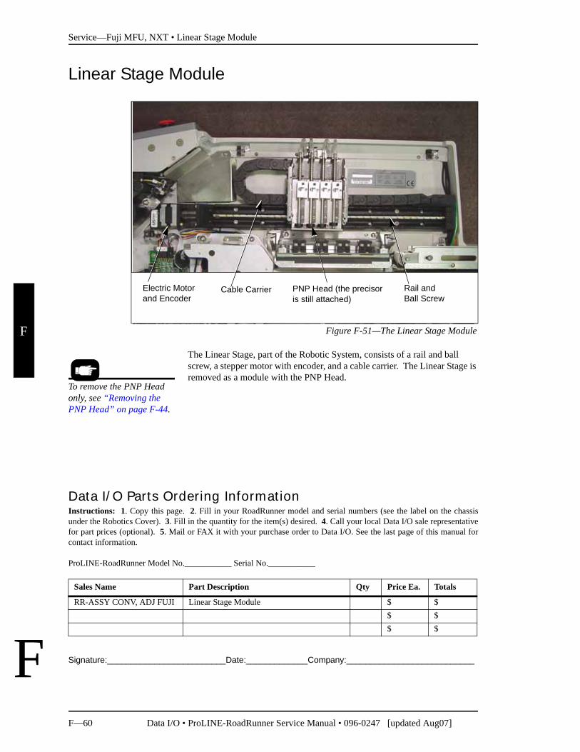
Linear Stage Module
Figure F-51—The Linear Stage Module
The Linear Stage, part of the Robotic System, consists of a rail and ball screw, a stepper motor with encoder, and a cable carrier. The Linear Stage is removed as a module with the PNP Head.
Signature:_________________________Date:_____________Company:___________________________
Electric Motor and Encoder
Rail and Ball Screw
PNP Head (the precisor is still attached)
Cable Carrier
To remove the PNP Head only, see “Removing the PNP Head” on page F-44.
Data I/O Parts Ordering InformationInstructions: 1. Copy this page. 2. Fill in your RoadRunner model and serial numbers (see the label on the chassisunder the Robotics Cover). 3. Fill in the quantity for the item(s) desired. 4. Call your local Data I/O sale representativefor part prices (optional). 5. Mail or FAX it with your purchase order to Data I/O. See the last page of this manual forcontact information.
ProLINE-RoadRunner Model No.___________ Serial No.___________
Sales Name Part Description Qty Price Ea. Totals
RR-ASSY CONV, ADJ FUJI Linear Stage Module $ $$ $$ $
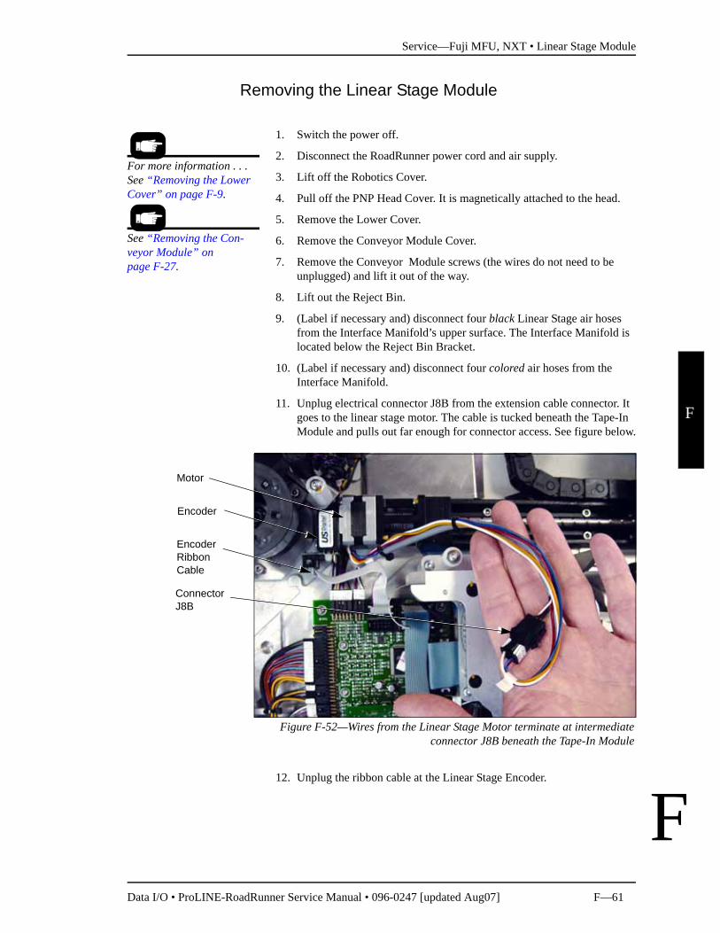
Service—Fuji MFU, NXT • Linear Stage Module
Data I/O • ProLINE-RoadRunner Service Manual • 096-0247 [updated Aug07] F—61
F
F
Removing the Linear Stage Module
1. Switch the power off.
2. Disconnect the RoadRunner power cord and air supply.
3. Lift off the Robotics Cover.
4. Pull off the PNP Head Cover. It is magnetically attached to the head.
5. Remove the Lower Cover.
6. Remove the Conveyor Module Cover.
7. Remove the Conveyor Module screws (the wires do not need to be unplugged) and lift it out of the way.
8. Lift out the Reject Bin.
9. (Label if necessary and) disconnect four black Linear Stage air hoses from the Interface Manifold’s upper surface. The Interface Manifold is located below the Reject Bin Bracket.
10. (Label if necessary and) disconnect four colored air hoses from the Interface Manifold.
11. Unplug electrical connector J8B from the extension cable connector. It goes to the linear stage motor. The cable is tucked beneath the Tape-In Module and pulls out far enough for connector access. See figure below.
Figure F-52—Wires from the Linear Stage Motor terminate at intermediateconnector J8B beneath the Tape-In Module
12. Unplug the ribbon cable at the Linear Stage Encoder.
For more information . . . See “Removing the Lower Cover” on page F-9.
See “Removing the Con-veyor Module” on page F-27.
Motor
Encoder
Encoder Ribbon Cable
Connector J8B
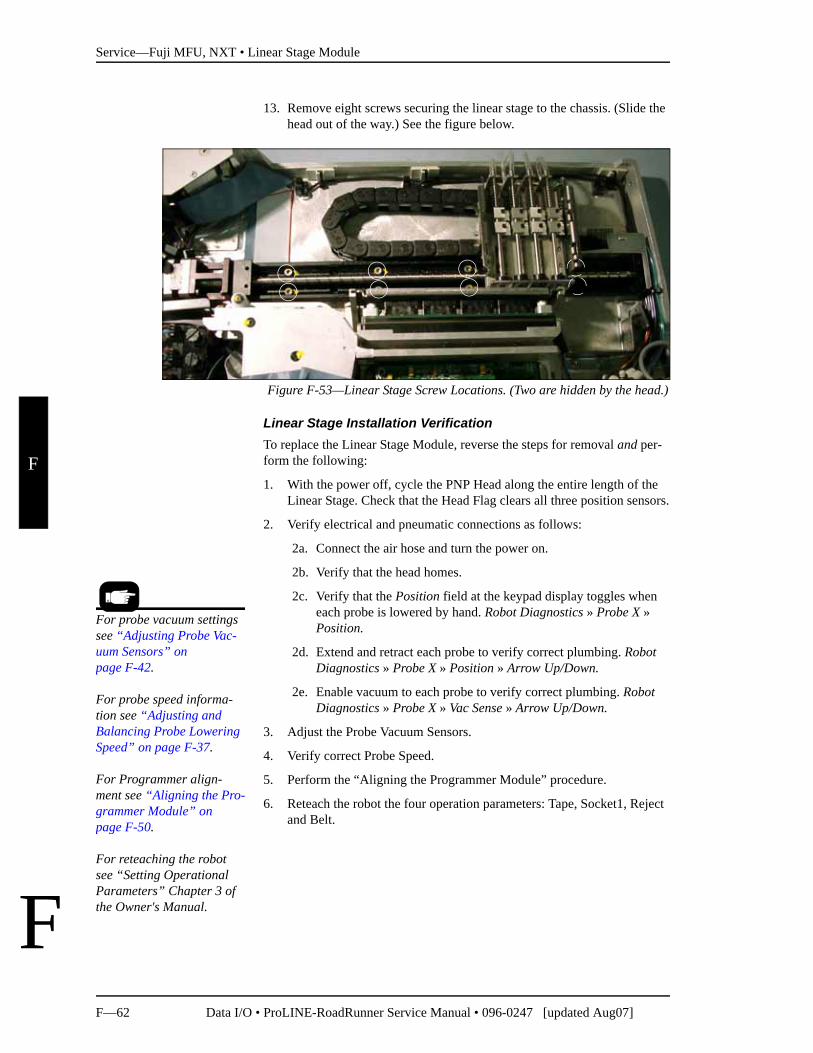
Service—Fuji MFU, NXT • Linear Stage Module
F—62 Data I/O • ProLINE-RoadRunner Service Manual • 096-0247 [updated Aug07]
F
F
13. Remove eight screws securing the linear stage to the chassis. (Slide the head out of the way.) See the figure below.
Figure F-53—Linear Stage Screw Locations. (Two are hidden by the head.)
Linear Stage Installation VerificationTo replace the Linear Stage Module, reverse the steps for removal and per-form the following:
1. With the power off, cycle the PNP Head along the entire length of the Linear Stage. Check that the Head Flag clears all three position sensors.
2. Verify electrical and pneumatic connections as follows:
2a. Connect the air hose and turn the power on.
2b. Verify that the head homes.
2c. Verify that the Position field at the keypad display toggles when each probe is lowered by hand. Robot Diagnostics » Probe X » Position.
2d. Extend and retract each probe to verify correct plumbing. Robot Diagnostics » Probe X » Position » Arrow Up/Down.
2e. Enable vacuum to each probe to verify correct plumbing. Robot Diagnostics » Probe X » Vac Sense » Arrow Up/Down.
3. Adjust the Probe Vacuum Sensors.
4. Verify correct Probe Speed.
5. Perform the “Aligning the Programmer Module” procedure.
6. Reteach the robot the four operation parameters: Tape, Socket1, Reject and Belt.
For probe vacuum settings see “Adjusting Probe Vac-uum Sensors” on page F-42.
For probe speed informa-tion see “Adjusting and Balancing Probe Lowering Speed” on page F-37.
For Programmer align-ment see “Aligning the Pro-grammer Module” on page F-50.
For reteaching the robot see “Setting Operational Parameters” Chapter 3 of the Owner's Manual.
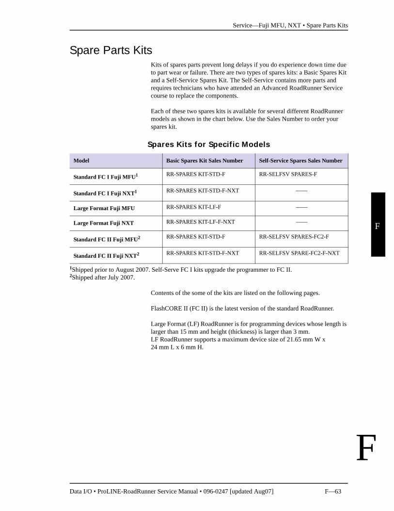
Service—Fuji MFU, NXT • Spare Parts Kits
Data I/O • ProLINE-RoadRunner Service Manual • 096-0247 [updated Aug07] F—63
F
F
Spare Parts KitsKits of spares parts prevent long delays if you do experience down time due to part wear or failure. There are two types of spares kits: a Basic Spares Kit and a Self-Service Spares Kit. The Self-Service contains more parts and requires technicians who have attended an Advanced RoadRunner Service course to replace the components.
Each of these two spares kits is available for several different RoadRunner models as shown in the chart below. Use the Sales Number to order your spares kit.
1Shipped prior to August 2007. Self-Serve FC I kits upgrade the programmer to FC II.2Shipped after July 2007.
Contents of the some of the kits are listed on the following pages.
FlashCORE II (FC II) is the latest version of the standard RoadRunner.
Large Format (LF) RoadRunner is for programming devices whose length is larger than 15 mm and height (thickness) is larger than 3 mm. LF RoadRunner supports a maximum device size of 21.65 mm W x 24 mm L x 6 mm H.
Spares Kits for Specific Models
Model Basic Spares Kit Sales Number Self-Service Spares Sales Number
Standard FC I Fuji MFU1 RR-SPARES KIT-STD-F RR-SELFSV SPARES-F
Standard FC I Fuji NXT1 RR-SPARES KIT-STD-F-NXT ——
Large Format Fuji MFU RR-SPARES KIT-LF-F ——
Large Format Fuji NXT RR-SPARES KIT-LF-F-NXT ——
Standard FC II Fuji MFU2 RR-SPARES KIT-STD-F RR-SELFSV SPARES-FC2-F
Standard FC II Fuji NXT2 RR-SPARES KIT-STD-F-NXT RR-SELFSV SPARE-FC2-F-NXT
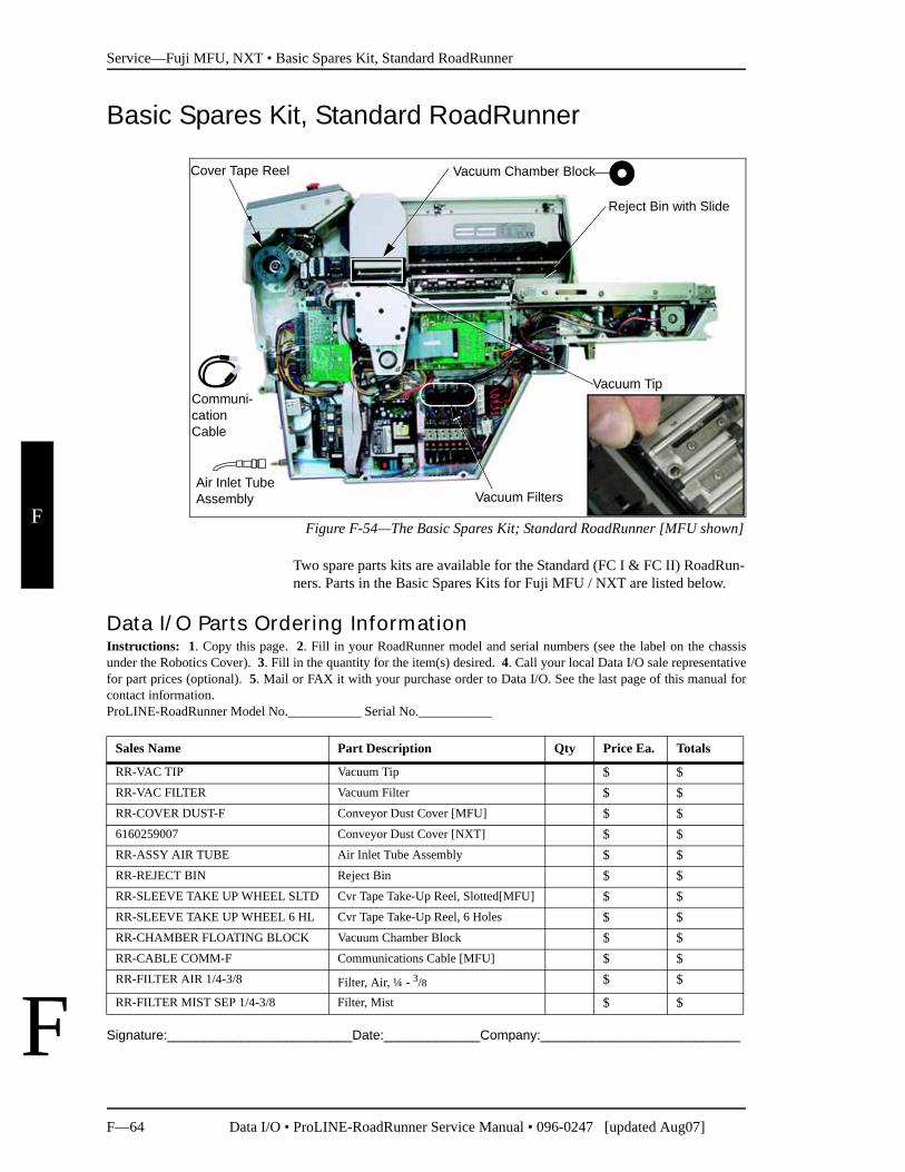
Service—Fuji MFU, NXT • Basic Spares Kit, Standard RoadRunner
F—64 Data I/O • ProLINE-RoadRunner Service Manual • 096-0247 [updated Aug07]
F
F
Basic Spares Kit, Standard RoadRunner
Figure F-54—The Basic Spares Kit; Standard RoadRunner [MFU shown]
Two spare parts kits are available for the Standard (FC I & FC II) RoadRun-ners. Parts in the Basic Spares Kits for Fuji MFU / NXT are listed below.
Signature:_________________________Date:_____________Company:___________________________
Communi-cation Cable
Vacuum Tip
Vacuum Filters
Reject Bin with Slide
Cover Tape Reel
Air Inlet Tube Assembly
Vacuum Chamber Block
Data I/O Parts Ordering InformationInstructions: 1. Copy this page. 2. Fill in your RoadRunner model and serial numbers (see the label on the chassisunder the Robotics Cover). 3. Fill in the quantity for the item(s) desired. 4. Call your local Data I/O sale representativefor part prices (optional). 5. Mail or FAX it with your purchase order to Data I/O. See the last page of this manual forcontact information.ProLINE-RoadRunner Model No.___________ Serial No.___________
Sales Name Part Description Qty Price Ea. Totals
RR-VAC TIP Vacuum Tip $ $RR-VAC FILTER Vacuum Filter $ $RR-COVER DUST-F Conveyor Dust Cover [MFU] $ $6160259007 Conveyor Dust Cover [NXT] $ $RR-ASSY AIR TUBE Air Inlet Tube Assembly $ $RR-REJECT BIN Reject Bin $ $RR-SLEEVE TAKE UP WHEEL SLTD Cvr Tape Take-Up Reel, Slotted[MFU] $ $RR-SLEEVE TAKE UP WHEEL 6 HL Cvr Tape Take-Up Reel, 6 Holes $ $RR-CHAMBER FLOATING BLOCK Vacuum Chamber Block $ $RR-CABLE COMM-F Communications Cable [MFU] $ $RR-FILTER AIR 1/4-3/8 Filter, Air, ¼ - 3/8 $ $
RR-FILTER MIST SEP 1/4-3/8 Filter, Mist $ $
Service—Fuji MFU, NXT • Basic Spares Kit, Standard RoadRunner
Data I/O • ProLINE-RoadRunner Service Manual • 096-0247 [updated Aug07] F—65
F
F
Replacing Probe Tips
The rubber tip pulls straight off. Hold a new tip with the square hole oriented to the square end of the probe and work it onto the probe.
Small diameter probe tips are available for running devices with a length or width of 4 mm or less. To order, use Sales Number 2880020001.
Make sure that all probe tips are the same size.
Replacing the Air Inlet Tube Assembly
To remove the Air Inlet Tube Assembly at the RoadRunner air connector:
1. Stop or pause the job if one is running.
2. If there are any devices currently on the probes, remove them; they will fall off when air is removed.
3. Pull the collar on the quick release fitting back as you pull the tube assembly off the connector. (The quick release fitting has a safety shut off feature—the compressed air need not be turned off.)
To connect an Air Inlet Tube Assembly, push it onto the RoadRunner con-nector.
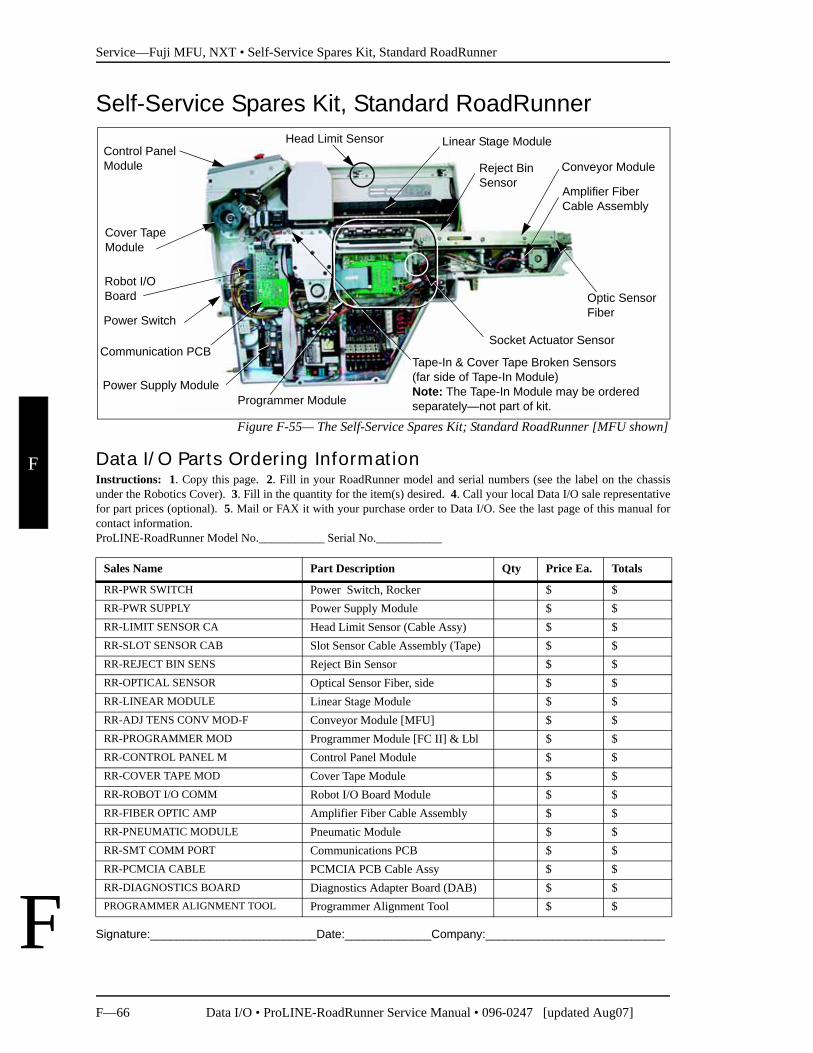
Service—Fuji MFU, NXT • Self-Service Spares Kit, Standard RoadRunner
F—66 Data I/O • ProLINE-RoadRunner Service Manual • 096-0247 [updated Aug07]
F
F
Self-Service Spares Kit, Standard RoadRunner
Figure F-55— The Self-Service Spares Kit; Standard RoadRunner [MFU shown]
Signature:_________________________Date:_____________Company:___________________________
Linear Stage ModuleControl Panel Module
Head Limit Sensor
Conveyor Module
Socket Actuator Sensor
Programmer Module
Robot I/O Board
Cover Tape Module
Optic Sensor Fiber
Tape-In & Cover Tape Broken Sensors(far side of Tape-In Module) Note: The Tape-In Module may be ordered separately—not part of kit.
Power Switch
Reject BinSensor
Power Supply Module
Amplifier Fiber Cable Assembly
Communication PCB
Data I/O Parts Ordering InformationInstructions: 1. Copy this page. 2. Fill in your RoadRunner model and serial numbers (see the label on the chassisunder the Robotics Cover). 3. Fill in the quantity for the item(s) desired. 4. Call your local Data I/O sale representativefor part prices (optional). 5. Mail or FAX it with your purchase order to Data I/O. See the last page of this manual forcontact information.ProLINE-RoadRunner Model No.___________ Serial No.___________
Sales Name Part Description Qty Price Ea. Totals
RR-PWR SWITCH Power Switch, Rocker $ $RR-PWR SUPPLY Power Supply Module $ $RR-LIMIT SENSOR CA Head Limit Sensor (Cable Assy) $ $RR-SLOT SENSOR CAB Slot Sensor Cable Assembly (Tape) $ $RR-REJECT BIN SENS Reject Bin Sensor $ $RR-OPTICAL SENSOR Optical Sensor Fiber, side $ $RR-LINEAR MODULE Linear Stage Module $ $RR-ADJ TENS CONV MOD-F Conveyor Module [MFU] $ $RR-PROGRAMMER MOD Programmer Module [FC II] & Lbl $ $RR-CONTROL PANEL M Control Panel Module $ $RR-COVER TAPE MOD Cover Tape Module $ $RR-ROBOT I/O COMM Robot I/O Board Module $ $RR-FIBER OPTIC AMP Amplifier Fiber Cable Assembly $ $RR-PNEUMATIC MODULE Pneumatic Module $ $RR-SMT COMM PORT Communications PCB $ $RR-PCMCIA CABLE PCMCIA PCB Cable Assy $ $RR-DIAGNOSTICS BOARD Diagnostics Adapter Board (DAB) $ $PROGRAMMER ALIGNMENT TOOL Programmer Alignment Tool $ $
Service—Fuji MFU, NXT • Self-Service Spares Kit, Standard RoadRunner
Data I/O • ProLINE-RoadRunner Service Manual • 096-0247 [updated Aug07] F—67
F
F
The Self-Service Spares Kit for Standard FC I Fuji MFU (RR-SELFSV SPARES-F) contains parts listed on the previous page. It is available to those who have attended an Advanced RoadRunner Service course.
Customer TrainingFor information about advanced training, contact the Data I/O Customer Service Center. A training course may be ordered when purchasing a RoadRunner or at a later time.
NOTE: This manual does not list replacement instructions for all the parts in the Self-Service Spares Kit. For additional information, contact Data I/O or your nearest authorized representative.
To find your nearest representative, see the instructions on the last page of this manual.
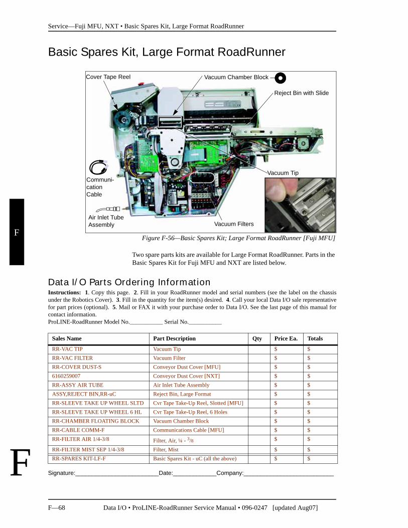
Service—Fuji MFU, NXT • Basic Spares Kit, Large Format RoadRunner
F—68 Data I/O • ProLINE-RoadRunner Service Manual • 096-0247 [updated Aug07]
F
F
Basic Spares Kit, Large Format RoadRunner
Figure F-56—Basic Spares Kit; Large Format RoadRunner [Fuji MFU]
Two spare parts kits are available for Large Format RoadRunner. Parts in the Basic Spares Kit for Fuji MFU and NXT are listed below.
Signature:_________________________Date:_____________Company:___________________________
Communi-cation Cable
Vacuum Tip
Vacuum Filters
Reject Bin with Slide
Cover Tape Reel
Air Inlet Tube Assembly
Vacuum Chamber Block
Data I/O Parts Ordering InformationInstructions: 1. Copy this page. 2. Fill in your RoadRunner model and serial numbers (see the label on the chassisunder the Robotics Cover). 3. Fill in the quantity for the item(s) desired. 4. Call your local Data I/O sale representativefor part prices (optional). 5. Mail or FAX it with your purchase order to Data I/O. See the last page of this manual forcontact information.ProLINE-RoadRunner Model No.___________ Serial No.___________
Sales Name Part Description Qty Price Ea. Totals
RR-VAC TIP Vacuum Tip $ $RR-VAC FILTER Vacuum Filter $ $RR-COVER DUST-S Conveyor Dust Cover [MFU] $ $6160259007 Conveyor Dust Cover [NXT] $ $RR-ASSY AIR TUBE Air Inlet Tube Assembly $ $ASSY,REJECT BIN,RR-uC Reject Bin, Large Format $ $RR-SLEEVE TAKE UP WHEEL SLTD Cvr Tape Take-Up Reel, Slotted [MFU] $ $RR-SLEEVE TAKE UP WHEEL 6 HL Cvr Tape Take-Up Reel, 6 Holes $ $RR-CHAMBER FLOATING BLOCK Vacuum Chamber Block $ $RR-CABLE COMM-F Communications Cable [MFU] $ $RR-FILTER AIR 1/4-3/8 Filter, Air, ¼ - 3/8 $ $
RR-FILTER MIST SEP 1/4-3/8 Filter, Mist $ $RR-SPARES KIT-LF-F Basic Spares Kit - uC (all the above) $ $
Service—Fuji MFU, NXT • Basic Spares Kit, Large Format RoadRunner
Data I/O • ProLINE-RoadRunner Service Manual • 096-0247 [updated Aug07] F—69
F
F
Replacing Probe Tips
The rubber tip pulls straight off. Hold a new tip with the square hole oriented to the square end of the probe and work it onto the probe.
Replacing the Air Inlet Tube Assembly
To remove the Air Inlet Tube Assembly at the RoadRunner air connector:
1. Stop or pause the job if one is running.
2. If there are any devices currently on the probes, remove them; they will fall off when air is removed.
3. Pull the collar on the quick release fitting back as you pull the tube assembly off the connector. (The quick release fitting has a safety shut off feature—the compressed air need not be turned off.)
To connect an Air Inlet Tube Assembly, push it onto the RoadRunner con-nector.
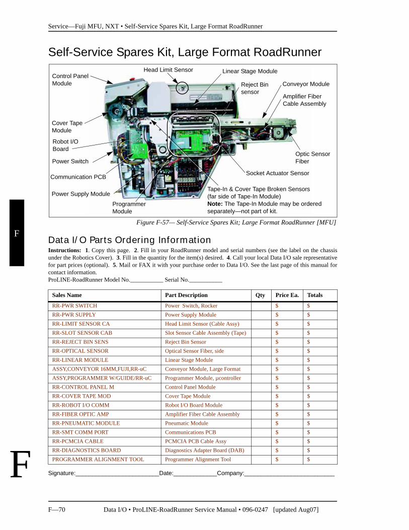
Service—Fuji MFU, NXT • Self-Service Spares Kit, Large Format RoadRunner
F—70 Data I/O • ProLINE-RoadRunner Service Manual • 096-0247 [updated Aug07]
F
F
Self-Service Spares Kit, Large Format RoadRunner
Figure F-57— Self-Service Spares Kit; Large Format RoadRunner [MFU]
Signature:_________________________Date:_____________Company:___________________________
Linear Stage ModuleControl Panel Module
Head Limit Sensor
Conveyor Module
Socket Actuator Sensor
Programmer Module
Robot I/O Board
Cover Tape Module
Optic Sensor Fiber
Tape-In & Cover Tape Broken Sensors(far side of Tape-In Module) Note: The Tape-In Module may be ordered separately—not part of kit.
Power Switch
Reject Binsensor
Power Supply Module
Amplifier Fiber Cable Assembly
Communication PCB
Data I/O Parts Ordering InformationInstructions: 1. Copy this page. 2. Fill in your RoadRunner model and serial numbers (see the label on the chassisunder the Robotics Cover). 3. Fill in the quantity for the item(s) desired. 4. Call your local Data I/O sale representativefor part prices (optional). 5. Mail or FAX it with your purchase order to Data I/O. See the last page of this manual forcontact information.ProLINE-RoadRunner Model No.___________ Serial No.___________
Sales Name Part Description Qty Price Ea. Totals
RR-PWR SWITCH Power Switch, Rocker $ $RR-PWR SUPPLY Power Supply Module $ $RR-LIMIT SENSOR CA Head Limit Sensor (Cable Assy) $ $RR-SLOT SENSOR CAB Slot Sensor Cable Assembly (Tape) $ $RR-REJECT BIN SENS Reject Bin Sensor $ $RR-OPTICAL SENSOR Optical Sensor Fiber, side $ $RR-LINEAR MODULE Linear Stage Module $ $ASSY,CONVEYOR 16MM,FUJI,RR-uC Conveyor Module, Large Format $ $ASSY,PROGRAMMER W/GUIDE/RR-uC Programmer Module, µcontroller $ $RR-CONTROL PANEL M Control Panel Module $ $RR-COVER TAPE MOD Cover Tape Module $ $RR-ROBOT I/O COMM Robot I/O Board Module $ $RR-FIBER OPTIC AMP Amplifier Fiber Cable Assembly $ $RR-PNEUMATIC MODULE Pneumatic Module $ $RR-SMT COMM PORT Communications PCB $ $RR-PCMCIA CABLE PCMCIA PCB Cable Assy $ $RR-DIAGNOSTICS BOARD Diagnostics Adapter Board (DAB) $ $PROGRAMMER ALIGNMENT TOOL Programmer Alignment Tool $ $
Service—Fuji MFU, NXT • Self-Service Spares Kit, Large Format RoadRunner
Data I/O • ProLINE-RoadRunner Service Manual • 096-0247 [updated Aug07] F—71
F
F
The Self-Service Spares Kit for Large Format RoadRunner contains parts listed on the previous page. It is available to those who have attended an Advanced RoadRunner Service course.
Customer TrainingFor information about advanced training, contact the Data I/O Customer Service Center. A training course may be ordered when purchasing a RoadRunner or at a later time.
NOTE: This manual does not list replacement instructions for all the parts in the Self-Service Spares Kit. For additional information, contact Data I/O or your nearest authorized representative. To find your nearest representative, see the instructions on the last page of this manual.
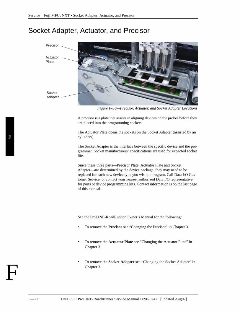
Service—Fuji MFU, NXT • Socket Adapter, Actuator, and Precisor
F—72 Data I/O • ProLINE-RoadRunner Service Manual • 096-0247 [updated Aug07]
F
F
Socket Adapter, Actuator, and Precisor
Figure F-58—Precisor, Actuator, and Socket Adapter Locations
A precisor is a plate that assists in aligning devices on the probes before they are placed into the programming sockets.
The Actuator Plate opens the sockets on the Socket Adapter (assisted by air cylinders).
The Socket Adapter is the interface between the specific device and the pro-grammer. Socket manufacturers’ specifications are used for expected socket life.
Since these three parts—Precisor Plate, Actuator Plate and Socket Adapter—are determined by the device package, they may need to be replaced for each new device type you wish to program. Call Data I/O Cus-tomer Service, or contact your nearest authorized Data I/O representative, for parts or device programming kits. Contact information is on the last page of this manual.
See the ProLINE-RoadRunner Owner’s Manual for the following:
• To remove the Precisor see “Changing the Precisor” in Chapter 3.
• To remove the Actuator Plate see “Changing the Actuator Plate” in Chapter 3.
• To remove the Socket Adapter see “Changing the Socket Adapter” in Chapter 3.
Socket Adapter
Precisor
Actuator Plate
Data I/O • ProLINE-RoadRunner Service Manual • 096-0247 Index—1
Alphabetical
GIndex
NOTE: For items not found here, check the RoadRunner Owner’s Manual.
AActuation speed F-51Adjustable Tape-In Module
aligning F-14removing F-13
Air Filtersdescription F-18ordering F-18replacing F-19
Air Paths, keeping clean F-18
BBasic Spares Kit
Microcontroller F-68ordering F-64, F-68Standard F-64
Battery F-54Broken tape sensor F-16
CComponents, listed F-4Contact Information. See inside back cover.Control Panel Module
ordering F-34removing F-35
Conveyor Belt Cover, removing F-10Conveyor Drive Belt, adjusting F-28Conveyor Dust Cover, removing F-10Conveyor Module F-26, F-31, F-66
drop height F-27Microcontroller F-70reinstalling F-27removing F-27
Cover Tape broken sensor F-16Cover Tape Module
ordering F-24removing F-25
Covers, ordering F-8Customer Training F-67, F-71
DDelay Times, resetting F-41
EElectrostatic Discharge F-iiiEnd-of-Belt Sensor
adjusting F-29reteaching F-30testing F-29
ESD. See Electrostatic Discharge
Index • F+
Index—2 Data I/O • ProLINE-RoadRunner Service Manual • 096-0247
I
FFilter
mist separator F-68vacuum F-68
FlashCORE II F-63Front Cover, removing F-9
GGrounding F-iii
II/O Board F-66, F-70Interconnect Panel F-48Interface Manifold F-38
LLarge Format F-63Large Format RoadRunners F-1LF, see Large FormatLower Cover, removing F-9
MManifold, pneumatic F-18MFU RoadRunner F-1Modules
pictured F-4replaceable F-2
Motion Controller PCB F-5
NNVRAM battery F-54
installing F-57removing F-55reteaching F-58
NXT RoadRunner F-1
OOrder Form
Basic Spares Kit/Parts F-64, F-68Control Panel Module F-34Conveyor Belt Module F-26Cover Tape Module F-24Covers F-8Linear Stage Module F-60NVRAM Battery F-54Pneumatic Module F-18
PNP Head F-44Programmer Module F-46Reject Bin F-32Self-Service Spares Kit/Parts F-66, F-70Tape-In Module F-12Vacuum Filters F-18
Overview of Components F-4
PPick and Place Head
aligning F-37ordering F-44removing F-44 to F-45
Pick and Place Head Cover, removing F-9Pick delay time F-41Pick Sensor. See End-of-Belt SensorPneumatic Module
adjusting. See Probe, vacuum sensor.reinstalling F-23removing F-20
PowerCap Module, see NVRAM batteryProbe
balancing speed F-37raising speed F-38speed specification F-38speed, adjusting F-37vacuum sensor, adjusting F-42
Probe Tipreplacing F-65small diameter F-65
Probe Tip, replacing F-69
“I don’t see Rosetta in here. It should be here.”
Let us know about the items you can’t find by e-mailing:[email protected].
Index • R+
Data I/O • ProLINE-RoadRunner Service Manual • 096-0247 Index—3
I
Programmer Actuate Speed F-51Programmer Module
alignment F-50alignment tool F-49description F-46reinstalling F-49removing F-47
Puff duration F-41
RReject Bin
bracket F-33full sensor F-32sensor removal F-33
Reteaching Head Positions F-58Robot I/O Board F-66, F-70
SSafety
grounding F-iiiprecautions F-iii
Self-Service Spares KitMicrocontroller, locations F-70ordering parts F-66, F-70Standard, locations F-66
Serial Number, location F-5Service
component overview (figure) F-4, F-6replacing assemblies F-1
SMT machines supported F-1Socket Adapter, wear F-46Spare parts F-66, F-70
Microcontroller, locating F-68ordering F-64, F-68Standard, locating F-64
Spares Kits F-63
TTape-In Module
aligning F-16jamming F-12ordering parts F-12removing F-15
Throughput F-37Time Settings F-58Training F-67, F-71Travel delay time F-41Tube fittings F-21
VVacuum Sensor (Probe), adjusting F-42
WWarning, electrical shock F-9Warranty work F-1
Sales and Technical Support
World Wide Data I/O Corporation6464 185th Ave N.E., Suite 101Redmond, WA USA 98052
Telephone: 425-881-6444inside US 1-800-332-8246
Fax: 425-867-6972E-mail: [email protected]
Contact Data I/O World Wide Support or your local representative. To find your local representative on our Web site, go to http://www.dataio.com and click (upper right), then click
(left side). Then follow the instructions.
When calling or writing, please provide the following information:
• RoadRunner Serial number• Software Version displayed on the keyboard screen at start-up (turn the power off and then on
again)• Detailed description of the problem you are experiencing (if any)• Error messages (if any) • Device manufacturer, part number, package style and number of pins (if device-related)• Name, telephone number and address
Contact UsRepresentative Search
www.dataio.com www.dataio.cn www.dataio.de
United States China Germany