Proline Promass E 300 HART - Endress+Hauser
194
Products Solutions Services Operating Instructions Proline Promass E 300 HART Coriolis flowmeter Keep co v e r h tig t w hile S pannu ng öffne n BA01484D/06/EN/01.16 71302785 Valid as of version 01.00.zz (Device firmware)
Transcript of Proline Promass E 300 HART - Endress+Hauser

Products Solutions Services
Operating InstructionsProline Promass E 300HARTCoriolis flowmeter
Keep cover
h
tig
t while
Spannung
öffn
en
BA01484D/06/EN/01.1671302785
Valid as of version01.00.zz (Device firmware)

2 Endress+Hauser
• Make sure the document is stored in a safe place such that it is always available whenworking on or with the device.
• To avoid danger to individuals or the facility, read the "Basic safety instructions" sectioncarefully, as well as all other safety instructions in the document that are specific toworking procedures.
• The manufacturer reserves the right to modify technical data without prior notice. YourEndress+Hauser Sales Center will supply you with current information and updates tothese instructions.

Table of contents
Endress+Hauser 3
Table of contents
1 Document information . . . . . . . . . . . . . . 61.1 Document function . . . . . . . . . . . . . . . . . . . . . 61.2 Symbols used . . . . . . . . . . . . . . . . . . . . . . . . . . 6
1.2.1 Safety symbols . . . . . . . . . . . . . . . . . . 61.2.2 Electrical symbols . . . . . . . . . . . . . . . . 61.2.3 Communication symbols . . . . . . . . . . . 61.2.4 Tool symbols . . . . . . . . . . . . . . . . . . . . 71.2.5 Symbols for certain types of
information . . . . . . . . . . . . . . . . . . . . 71.2.6 Symbols in graphics . . . . . . . . . . . . . . . 7
1.3 Documentation . . . . . . . . . . . . . . . . . . . . . . . . 81.3.1 Standard documentation . . . . . . . . . . . 81.3.2 Supplementary device-dependent
documentation . . . . . . . . . . . . . . . . . . 81.4 Registered trademarks . . . . . . . . . . . . . . . . . . . 9
2 Basic safety instructions . . . . . . . . . . . 102.1 Requirements for personnel . . . . . . . . . . . . . . 102.2 Designated use . . . . . . . . . . . . . . . . . . . . . . . 102.3 Workplace safety . . . . . . . . . . . . . . . . . . . . . . 112.4 Operational safety . . . . . . . . . . . . . . . . . . . . . 112.5 Product safety . . . . . . . . . . . . . . . . . . . . . . . . 112.6 IT security . . . . . . . . . . . . . . . . . . . . . . . . . . . 122.7 Device-specific IT security . . . . . . . . . . . . . . . . 12
2.7.1 Protecting access via hardware writeprotection . . . . . . . . . . . . . . . . . . . . . 12
2.7.2 Protecting access via a password . . . . 122.7.3 Access via fieldbus . . . . . . . . . . . . . . . 132.7.4 Access via Web server . . . . . . . . . . . . 13
3 Product description . . . . . . . . . . . . . . . . 143.1 Product design . . . . . . . . . . . . . . . . . . . . . . . . 14
4 Incoming acceptance and productidentification . . . . . . . . . . . . . . . . . . . . . 15
4.1 Incoming acceptance . . . . . . . . . . . . . . . . . . . 154.2 Product identification . . . . . . . . . . . . . . . . . . . 16
4.2.1 Transmitter nameplate . . . . . . . . . . . 174.2.2 Sensor nameplate . . . . . . . . . . . . . . . 184.2.3 Symbols on measuring device . . . . . . 19
5 Storage and transport . . . . . . . . . . . . . 205.1 Storage conditions . . . . . . . . . . . . . . . . . . . . . 205.2 Transporting the product . . . . . . . . . . . . . . . . 20
5.2.1 Measuring devices without liftinglugs . . . . . . . . . . . . . . . . . . . . . . . . . 20
5.2.2 Measuring devices with lifting lugs . . 215.2.3 Transporting with a fork lift . . . . . . . . 21
5.3 Packaging disposal . . . . . . . . . . . . . . . . . . . . . 21
6 Installation . . . . . . . . . . . . . . . . . . . . . . . 226.1 Installation conditions . . . . . . . . . . . . . . . . . . 22
6.1.1 Mounting position . . . . . . . . . . . . . . . 226.1.2 Requirements from environment and
process . . . . . . . . . . . . . . . . . . . . . . . 246.1.3 Special mounting instructions . . . . . . 26
6.2 Mounting the measuring device . . . . . . . . . . . 286.2.1 Required tools . . . . . . . . . . . . . . . . . . 286.2.2 Preparing the measuring device . . . . . 286.2.3 Mounting the measuring device . . . . . 286.2.4 Turning the transmitter housing . . . . 286.2.5 Turning the display module . . . . . . . . 29
6.3 Post-installation check . . . . . . . . . . . . . . . . . . 30
7 Electrical connection . . . . . . . . . . . . . . 317.1 Connection conditions . . . . . . . . . . . . . . . . . . 31
7.1.1 Required tools . . . . . . . . . . . . . . . . . . 317.1.2 Requirements for connecting cable . . . 317.1.3 Terminal assignment . . . . . . . . . . . . . 337.1.4 Preparing the measuring device . . . . . 33
7.2 Connecting the measuring device . . . . . . . . . . 337.2.1 Connecting the transmitter . . . . . . . . 337.2.2 Connecting remote display and
operating module DKX001 . . . . . . . . 367.3 Ensure potential equalization . . . . . . . . . . . . . 36
7.3.1 Requirements . . . . . . . . . . . . . . . . . . 367.4 Special connection instructions . . . . . . . . . . . . 37
7.4.1 Connection examples . . . . . . . . . . . . . 377.5 Ensuring the degree of protection . . . . . . . . . . 417.6 Post-connection check . . . . . . . . . . . . . . . . . . 41
8 Operation options . . . . . . . . . . . . . . . . . 428.1 Overview of operation options . . . . . . . . . . . . 428.2 Structure and function of the operating
menu . . . . . . . . . . . . . . . . . . . . . . . . . . . . . . 438.2.1 Structure of the operating menu . . . . 438.2.2 Operating philosophy . . . . . . . . . . . . 44
8.3 Access to the operating menu via the localdisplay . . . . . . . . . . . . . . . . . . . . . . . . . . . . . 458.3.1 Operational display . . . . . . . . . . . . . . 458.3.2 Navigation view . . . . . . . . . . . . . . . . 468.3.3 Editing view . . . . . . . . . . . . . . . . . . . 488.3.4 Operating elements . . . . . . . . . . . . . . 508.3.5 Opening the context menu . . . . . . . . . 508.3.6 Navigating and selecting from list . . . 528.3.7 Calling the parameter directly . . . . . . 528.3.8 Calling up help text . . . . . . . . . . . . . . 538.3.9 Changing the parameters . . . . . . . . . 548.3.10 User roles and related access
authorization . . . . . . . . . . . . . . . . . . 558.3.11 Disabling write protection via access
code . . . . . . . . . . . . . . . . . . . . . . . . . 558.3.12 Enabling and disabling the keypad
lock . . . . . . . . . . . . . . . . . . . . . . . . . 55

Table of contents
4 Endress+Hauser
8.4 Access to the operating menu via the Webbrowser . . . . . . . . . . . . . . . . . . . . . . . . . . . . . 568.4.1 Function range . . . . . . . . . . . . . . . . . 568.4.2 Prerequisites . . . . . . . . . . . . . . . . . . . 568.4.3 Establishing a connection . . . . . . . . . 588.4.4 Logging on . . . . . . . . . . . . . . . . . . . . 598.4.5 User interface . . . . . . . . . . . . . . . . . . 608.4.6 Disabling the Web server . . . . . . . . . . 618.4.7 Logging out . . . . . . . . . . . . . . . . . . . . 61
8.5 Access to the operating menu via theoperating tool . . . . . . . . . . . . . . . . . . . . . . . . 618.5.1 Connecting the operating tool . . . . . . 628.5.2 Field Xpert SFX350, SFX370 . . . . . . . 648.5.3 FieldCare . . . . . . . . . . . . . . . . . . . . . 658.5.4 DeviceCare . . . . . . . . . . . . . . . . . . . . 668.5.5 AMS Device Manager . . . . . . . . . . . . 668.5.6 SIMATIC PDM . . . . . . . . . . . . . . . . . . 678.5.7 Field Communicator 475 . . . . . . . . . . 67
9 System integration . . . . . . . . . . . . . . . . 689.1 Overview of device description files . . . . . . . . . 68
9.1.1 Current version data for the device . . . 689.1.2 Operating tools . . . . . . . . . . . . . . . . . 68
9.2 Measured variables via HART protocol . . . . . . 689.3 Other settings . . . . . . . . . . . . . . . . . . . . . . . . 70
9.3.1 Burst mode functionality inaccordance with HART 7Specification . . . . . . . . . . . . . . . . . . . 70
10 Commissioning . . . . . . . . . . . . . . . . . . . . 7310.1 Function check . . . . . . . . . . . . . . . . . . . . . . . 7310.2 Switching on the measuring device . . . . . . . . . 7310.3 Setting the operating language . . . . . . . . . . . . 7310.4 Configuring the measuring device . . . . . . . . . . 73
10.4.1 Defining the tag name . . . . . . . . . . . . 7510.4.2 Setting the system units . . . . . . . . . . 7510.4.3 Selecting and setting the medium . . . 7810.4.4 Displaying the I/O configuration . . . . 7910.4.5 Configuring the current input . . . . . . 8010.4.6 Configuring the status input . . . . . . . 8110.4.7 Configuring the current output . . . . . 8210.4.8 Configuring the pulse/frequency/
switch output . . . . . . . . . . . . . . . . . . 8510.4.9 Configuring the relay output . . . . . . . 9410.4.10 Configuring the double pulse output . . 9610.4.11 Configuring the local display . . . . . . . 9710.4.12 Configuring the low flow cut off . . . . 10010.4.13 Configuring the partial filled pipe
detection . . . . . . . . . . . . . . . . . . . . 10110.5 Advanced settings . . . . . . . . . . . . . . . . . . . . 102
10.5.1 Using the parameter to enter theaccess code . . . . . . . . . . . . . . . . . . . 103
10.5.2 Calculated values . . . . . . . . . . . . . . . 10310.5.3 Carrying out a sensor adjustment . . . 10410.5.4 Configuring the totalizer . . . . . . . . . 10510.5.5 Carrying out additional display
configurations . . . . . . . . . . . . . . . . . 10710.5.6 WLAN configuration . . . . . . . . . . . . 110
10.5.7 Configuration management . . . . . . . 11110.5.8 Using parameters for device
administration . . . . . . . . . . . . . . . . 11310.6 Simulation . . . . . . . . . . . . . . . . . . . . . . . . . . 11410.7 Protecting settings from unauthorized
access . . . . . . . . . . . . . . . . . . . . . . . . . . . . . 11710.7.1 Write protection via access code . . . 11710.7.2 Write protection via write protection
switch . . . . . . . . . . . . . . . . . . . . . . . 119
11 Operation . . . . . . . . . . . . . . . . . . . . . . . 12011.1 Reading the device locking status . . . . . . . . . 12011.2 Adjusting the operating language . . . . . . . . . 12011.3 Configuring the display . . . . . . . . . . . . . . . . 12011.4 Reading measured values . . . . . . . . . . . . . . . 120
11.4.1 "Measured variables" submenu . . . . . 12111.4.2 "Totalizer" submenu . . . . . . . . . . . . . 12211.4.3 "Input values" submenu . . . . . . . . . . 12311.4.4 Output values . . . . . . . . . . . . . . . . . 124
11.5 Adapting the measuring device to the processconditions . . . . . . . . . . . . . . . . . . . . . . . . . . 126
11.6 Performing a totalizer reset . . . . . . . . . . . . . 12611.6.1 Function scope of the "Control
Totalizer" parameter . . . . . . . . . . . . 12711.6.2 Function scope of the "Reset all
totalizers" parameter . . . . . . . . . . . . 12811.7 Showing data logging . . . . . . . . . . . . . . . . . 128
12 Diagnostics and troubleshooting . . 13112.1 General troubleshooting . . . . . . . . . . . . . . . . 13112.2 Diagnostic information via light emitting
diodes . . . . . . . . . . . . . . . . . . . . . . . . . . . . . 13312.2.1 Transmitter . . . . . . . . . . . . . . . . . . . 133
12.3 Diagnostic information on local display . . . . . 13512.3.1 Diagnostic message . . . . . . . . . . . . . 13512.3.2 Calling up remedial measures . . . . . 137
12.4 Diagnostic information in the Web browser . 13712.4.1 Diagnostic options . . . . . . . . . . . . . . 13712.4.2 Calling up remedy information . . . . 138
12.5 Diagnostic information in DeviceCare orFieldCare . . . . . . . . . . . . . . . . . . . . . . . . . . . 13912.5.1 Diagnostic options . . . . . . . . . . . . . . 13912.5.2 Calling up remedy information . . . . 140
12.6 Adapting the diagnostic information . . . . . . 14012.6.1 Adapting the diagnostic behavior . . . 14012.6.2 Adapting the status signal . . . . . . . . 140
12.7 Overview of diagnostic information . . . . . . . 14112.8 Pending diagnostic events . . . . . . . . . . . . . . 14512.9 Diagnostic list . . . . . . . . . . . . . . . . . . . . . . . 14612.10 Event logbook . . . . . . . . . . . . . . . . . . . . . . . 146
12.10.1 Event history . . . . . . . . . . . . . . . . . . 14612.10.2 Filtering the event logbook . . . . . . . 14712.10.3 Overview of information events . . . . 147
12.11 Resetting the measuring device . . . . . . . . . . 14912.11.1 Function scope of the "Device reset"
parameter . . . . . . . . . . . . . . . . . . . . 14912.12 Device information . . . . . . . . . . . . . . . . . . . 14912.13 Firmware history . . . . . . . . . . . . . . . . . . . . . 151

Table of contents
Endress+Hauser 5
13 Maintenance . . . . . . . . . . . . . . . . . . . . 15213.1 Maintenance tasks . . . . . . . . . . . . . . . . . . . . 152
13.1.1 Exterior cleaning . . . . . . . . . . . . . . . 15213.1.2 Interior cleaning . . . . . . . . . . . . . . . 152
13.2 Measuring and test equipment . . . . . . . . . . . 15213.3 Endress+Hauser services . . . . . . . . . . . . . . . 152
14 Repairs . . . . . . . . . . . . . . . . . . . . . . . . . . 15314.1 General notes . . . . . . . . . . . . . . . . . . . . . . . 153
14.1.1 Repair and conversion concept . . . . . 15314.1.2 Notes for repair and conversion . . . . 153
14.2 Spare parts . . . . . . . . . . . . . . . . . . . . . . . . . 15314.3 Endress+Hauser services . . . . . . . . . . . . . . . 15314.4 Return . . . . . . . . . . . . . . . . . . . . . . . . . . . . . 15314.5 Disposal . . . . . . . . . . . . . . . . . . . . . . . . . . . 154
14.5.1 Removing the measuring device . . . . 15414.5.2 Disposing of the measuring device . . 154
15 Accessories . . . . . . . . . . . . . . . . . . . . . . 15515.1 Device-specific accessories . . . . . . . . . . . . . . 155
15.1.1 For the transmitter . . . . . . . . . . . . . 15515.1.2 For the sensor . . . . . . . . . . . . . . . . . 155
15.2 Communication-specific accessories . . . . . . . 15515.3 Service-specific accessories . . . . . . . . . . . . . . 15615.4 System components . . . . . . . . . . . . . . . . . . . 157
16 Technical data . . . . . . . . . . . . . . . . . . . 15816.1 Application . . . . . . . . . . . . . . . . . . . . . . . . . 15816.2 Function and system design . . . . . . . . . . . . . 15816.3 Input . . . . . . . . . . . . . . . . . . . . . . . . . . . . . . 15916.4 Output . . . . . . . . . . . . . . . . . . . . . . . . . . . . 16216.5 Power supply . . . . . . . . . . . . . . . . . . . . . . . . 16716.6 Performance characteristics . . . . . . . . . . . . . 16816.7 Installation . . . . . . . . . . . . . . . . . . . . . . . . . 17216.8 Environment . . . . . . . . . . . . . . . . . . . . . . . . 17216.9 Process . . . . . . . . . . . . . . . . . . . . . . . . . . . . 17316.10 Mechanical construction . . . . . . . . . . . . . . . 17416.11 Operability . . . . . . . . . . . . . . . . . . . . . . . . . 17716.12 Certificates and approvals . . . . . . . . . . . . . . 18216.13 Application packages . . . . . . . . . . . . . . . . . . 18416.14 Accessories . . . . . . . . . . . . . . . . . . . . . . . . . 18516.15 Supplementary documentation . . . . . . . . . . . 185
Index . . . . . . . . . . . . . . . . . . . . . . . . . . . . . . . . . 188
Document information Proline Promass E 300 HART
6 Endress+Hauser
1 Document information
1.1 Document functionThese Operating Instructions contain all the information that is required in various phasesof the life cycle of the device: from product identification, incoming acceptance andstorage, to mounting, connection, operation and commissioning through totroubleshooting, maintenance and disposal.
1.2 Symbols used
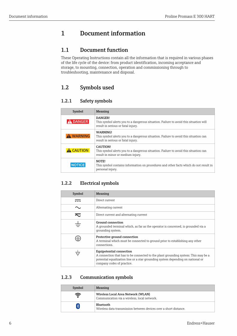
1.2.1 Safety symbols
Symbol Meaning
DANGER
DANGER!This symbol alerts you to a dangerous situation. Failure to avoid this situation willresult in serious or fatal injury.
WARNING
WARNING!This symbol alerts you to a dangerous situation. Failure to avoid this situation canresult in serious or fatal injury.
CAUTION
CAUTION!This symbol alerts you to a dangerous situation. Failure to avoid this situation canresult in minor or medium injury.
NOTICE
NOTE!This symbol contains information on procedures and other facts which do not result inpersonal injury.
1.2.2 Electrical symbols
Symbol Meaning
Direct current
Alternating current
Direct current and alternating current
Ground connectionA grounded terminal which, as far as the operator is concerned, is grounded via agrounding system.
Protective ground connectionA terminal which must be connected to ground prior to establishing any otherconnections.
Equipotential connectionA connection that has to be connected to the plant grounding system: This may be apotential equalization line or a star grounding system depending on national orcompany codes of practice.
1.2.3 Communication symbols
Symbol Meaning
Wireless Local Area Network (WLAN)Communication via a wireless, local network.
BluetoothWireless data transmission between devices over a short distance.

Proline Promass E 300 HART Document information
Endress+Hauser 7
Symbol Meaning
LEDLight emitting diode is off.
LEDLight emitting diode is on.
LEDLight emitting diode is flashing.
1.2.4 Tool symbols
Symbol Meaning
Flat blade screwdriver
Allen key
Open-ended wrench
1.2.5 Symbols for certain types of information
Symbol Meaning
PermittedProcedures, processes or actions that are permitted.
PreferredProcedures, processes or actions that are preferred.
ForbiddenProcedures, processes or actions that are forbidden.
TipIndicates additional information.
Reference to documentation
A Reference to page
Reference to graphic
Notice or individual step to be observed
1. , 2. , 3.… Series of steps
Result of a step
Help in the event of a problem
Visual inspection
1.2.6 Symbols in graphics
Symbol Meaning
1, 2, 3,... Item numbers
1. , 2. , 3.… Series of steps
A, B, C, ... Views
A-A, B-B, C-C, ... Sections

Document information Proline Promass E 300 HART
8 Endress+Hauser
Symbol Meaning
-Hazardous area
.Safe area (non-hazardous area)
Flow direction
1.3 DocumentationFor an overview of the scope of the associated Technical Documentation, refer to thefollowing:• The W@M Device Viewer : Enter the serial number from the nameplate
(www.endress.com/deviceviewer)• The Endress+Hauser Operations App: Enter the serial number from the nameplate
or scan the 2-D matrix code (QR code) on the nameplate.
For a detailed list of the individual documents along with the documentation code→ 185
1.3.1 Standard documentation
Document type Purpose and content of the document
Technical Information Planning aid for your deviceThe document contains all the technical data on the device and providesan overview of the accessories and other products that can be ordered forthe device.
Sensor Brief Operating Instructions Guides you quickly to the 1st measured value - Part 1The Sensor Brief Operating Instructions are aimed at specialists withresponsibility for installing the measuring device.
• Incoming acceptance and product identification• Storage and transport• Installation
Transmitter Brief OperatingInstructions
Guides you quickly to the 1st measured value - Part 2The Transmitter Brief Operating Instructions are aimed at specialists withresponsibility for commissioning, configuring and parameterizing themeasuring device (until the first measured value).
• Product description• Installation• Electrical connection• Operation options• System integration• Commissioning• Diagnostic information
Description of Device Parameters Reference for your parametersThe document provides a detailed explanation of each individualparameter in the Expert operating menu. The description is aimed atthose who work with the device over the entire life cycle and performspecific configurations.
1.3.2 Supplementary device-dependent documentationAdditional documents are supplied depending on the device version ordered: Alwayscomply strictly with the instructions in the supplementary documentation. Thesupplementary documentation is an integral part of the device documentation.

Proline Promass E 300 HART Document information
Endress+Hauser 9
1.4 Registered trademarksHART®
Registered trademark of the FieldComm Group, Austin, Texas, USA
TRI-CLAMP®
Registered trademark of Ladish & Co., Inc., Kenosha, USA
Applicator®, FieldCare®, DeviceCare ®, Field XpertTM, HistoROM®, HeartbeatTechnologyTM
Registered or registration-pending trademarks of the Endress+Hauser Group

Basic safety instructions Proline Promass E 300 HART
10 Endress+Hauser
2 Basic safety instructions
2.1 Requirements for personnelThe personnel for installation, commissioning, diagnostics and maintenance must fulfillthe following requirements:‣ Trained, qualified specialists must have a relevant qualification for this specific function
and task.‣ Are authorized by the plant owner/operator.‣ Are familiar with federal/national regulations.‣ Before starting work, read and understand the instructions in the manual and
supplementary documentation as well as the certificates (depending on theapplication).
‣ Follow instructions and comply with basic conditions.
The operating personnel must fulfill the following requirements:‣ Are instructed and authorized according to the requirements of the task by the facility's
owner-operator.‣ Follow the instructions in this manual.
2.2 Designated useApplication and mediaThe measuring device described in these Instructions is intended only for flowmeasurement of liquids and gases.
Depending on the version ordered, the measuring device can also measure potentiallyexplosive, flammable, poisonous and oxidizing media.
Measuring devices for use in hazardous areas, in hygienic applications or where there is anincreased risk due to process pressure, are labeled accordingly on the nameplate.
To ensure that the measuring device remains in proper condition for the operation time:‣ Only use the measuring device in full compliance with the data on the nameplate and
the general conditions listed in the Operating Instructions and supplementarydocumentation.
‣ Based on the nameplate, check whether the ordered device is permitted for theintended use in the hazardous area (e.g. explosion protection, pressure vessel safety).
‣ Use the measuring device only for media to which the process-wetted materials aresufficiently resistant.
‣ If the measuring device is not operated at atmospheric temperature, compliance withthe relevant basic conditions specified in the associated device documentation isabsolutely essential: "Documentation" section.→ 8.
‣ Protect the measuring device permanently against corrosion from environmentalinfluences.
Incorrect useNon-designated use can compromise safety. The manufacturer is not liable for damagecaused by improper or non-designated use.
LWARNINGDanger of breakage due to corrosive or abrasive fluids!‣ Verify the compatibility of the process fluid with the sensor material.‣ Ensure the resistance of all fluid-wetted materials in the process.‣ Keep within the specified pressure and temperature range.

Proline Promass E 300 HART Basic safety instructions
Endress+Hauser 11
NOTICEVerification for borderline cases:‣ For special fluids and fluids for cleaning, Endress+Hauser is glad to provide assistance
in verifying the corrosion resistance of fluid-wetted materials, but does not accept anywarranty or liability as minute changes in the temperature, concentration or level ofcontamination in the process can alter the corrosion resistance properties.
Residual risks
LWARNINGThe electronics and the medium may cause the surfaces to heat up. This presents aburn hazard!‣ For elevated fluid temperatures, ensure protection against contact to prevent burns.
LWARNINGDanger of housing breaking due to measuring tube breakage!‣ In the event of a measuring tube breakage for a device version without rupture disk it is
possible for the pressure loading capacity of the sensor housing to be exceeded. Thiscan lead to rupture or failure of the sensor housing.
2.3 Workplace safetyFor work on and with the device:‣ Wear the required personal protective equipment according to federal/national
regulations.
For welding work on the piping:‣ Do not ground the welding unit via the measuring device.
If working on and with the device with wet hands:‣ Due to the increased risk of electric shock, gloves must be worn.
2.4 Operational safetyRisk of injury.‣ Operate the device in proper technical condition and fail-safe condition only.‣ The operator is responsible for interference-free operation of the device.
Conversions to the deviceUnauthorized modifications to the device are not permitted and can lead to unforeseeabledangers.‣ If, despite this, modifications are required, consult with Endress+Hauser.
RepairTo ensure continued operational safety and reliability,‣ Carry out repairs on the device only if they are expressly permitted.‣ Observe federal/national regulations pertaining to repair of an electrical device.‣ Use original spare parts and accessories from Endress+Hauser only.
2.5 Product safetyThis measuring device is designed in accordance with good engineering practice to meetstate-of-the-art safety requirements, has been tested, and left the factory in a condition inwhich it is safe to operate.

Basic safety instructions Proline Promass E 300 HART
12 Endress+Hauser
It meets general safety standards and legal requirements. It also complies with the EUdirectives listed in the device-specific EU Declaration of Conformity. Endress+Hauserconfirms this by affixing the CE mark to the device.
2.6 IT securityWe only provide a warranty if the device is installed and used as described in theOperating Instructions. The device is equipped with security mechanisms to protect itagainst any inadvertent changes to the device settings.
IT security measures in line with operators' security standards and designed to provideadditional protection for the device and device data transfer must be implemented by theoperators themselves.
2.7 Device-specific IT securityThe device offers a range of specific functions to support protective measures on theoperator's side. These functions can be configured by the user and guarantee greater in-operation safety if used correctly. An overview of the most important functions is providedin the following section.
2.7.1 Protecting access via hardware write protectionWrite access to the device parameters via the local display, Web browser or operating tool(e.g. FieldCare, DeviceCare) can be disabled via a write protection switch (DIP switch onthe motherboard). When hardware write protection is enabled, only read access to theparameters is possible.
Hardware write protection is disabled when the device is delivered → 119.
2.7.2 Protecting access via a passwordDifferent passwords are available to protect write access to the device parameters or accessto the device via the WLAN interface.
• User-specific access codeProtect write access to the device parameters via the local display, Web browser oroperating tool (e.g. FieldCare, DeviceCare). Is equivalent to hardware write protection interms of functionality.
• WLAN passphraseThe network key protects a connection between an operating unit (e.g. notebook ortablet) and the device via the WLAN interface which can be ordered as an option.
User-specific access codeWrite access to the device parameters via the local display, Web browser or operating tool(e.g. FieldCare, DeviceCare) can be protected by the modifiable, user-specific access code(→ 117).
When the device is delivered, the device does not have an access code and is equivalent to0000 (open).
WLAN passphraseA connection between an operating unit (e.g. notebook or tablet) and the device via theWLAN interface (→ 63) which can be ordered as an option is protected by thenetwork key. The WLAN authentication of the network key complies with the IEEE 802.11standard.
Proline Promass E 300 HART Basic safety instructions
Endress+Hauser 13
When the device is delivered, the network key is pre-defined depending on the device. Itcan be changed via the WLAN settings submenu in the WLAN passphraseparameter→ 110.
General notes on the use of passwords• The access code and network key supplied with the device should be changed during
commissioning.• Follow the general rules for generating a secure password when defining and managing
the access code or network key.• The user is responsible for the management and careful handling of the access code and
network key.
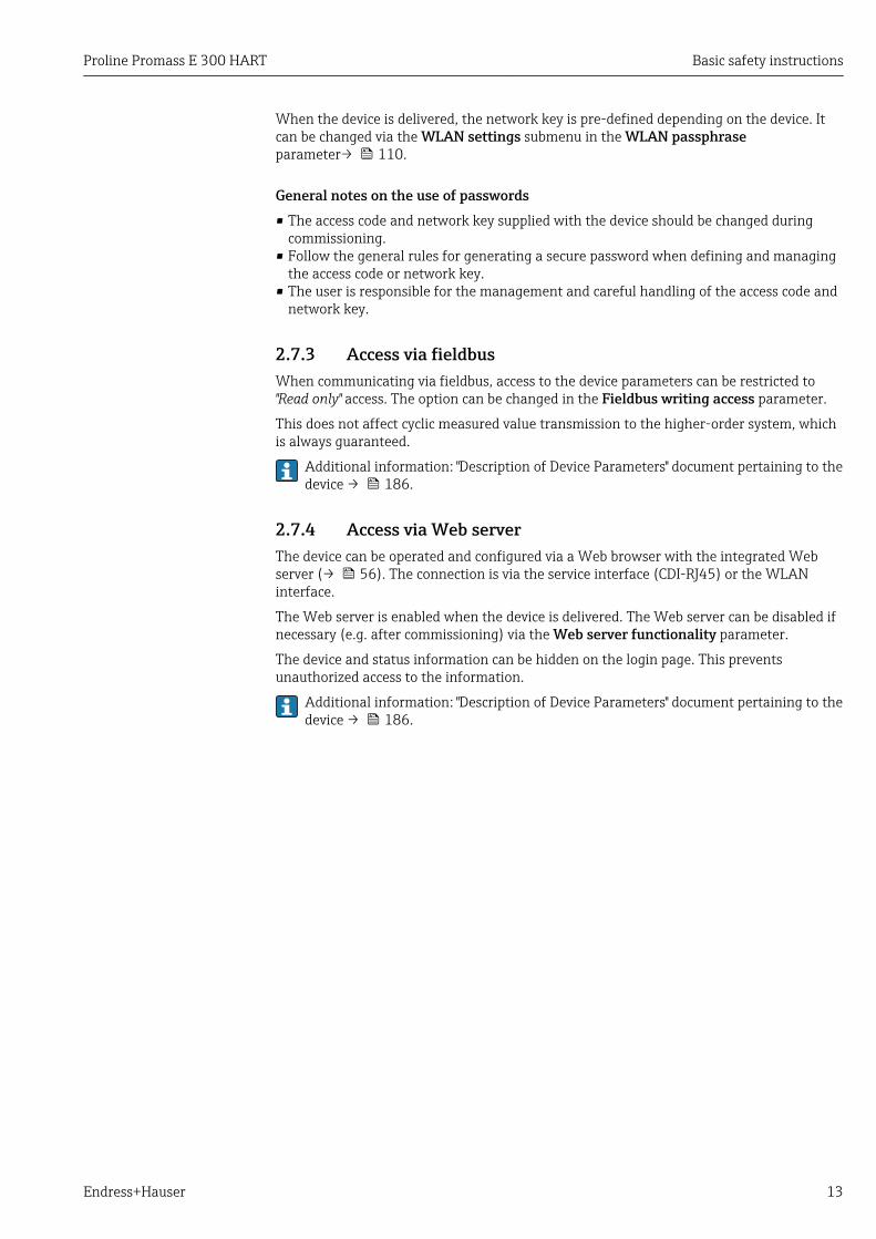
2.7.3 Access via fieldbusWhen communicating via fieldbus, access to the device parameters can be restricted to"Read only" access. The option can be changed in the Fieldbus writing access parameter.
This does not affect cyclic measured value transmission to the higher-order system, whichis always guaranteed.
Additional information: "Description of Device Parameters" document pertaining to thedevice → 186.
2.7.4 Access via Web serverThe device can be operated and configured via a Web browser with the integrated Webserver (→ 56). The connection is via the service interface (CDI-RJ45) or the WLANinterface.
The Web server is enabled when the device is delivered. The Web server can be disabled ifnecessary (e.g. after commissioning) via the Web server functionality parameter.
The device and status information can be hidden on the login page. This preventsunauthorized access to the information.
Additional information: "Description of Device Parameters" document pertaining to thedevice → 186.
Product description Proline Promass E 300 HART
14 Endress+Hauser
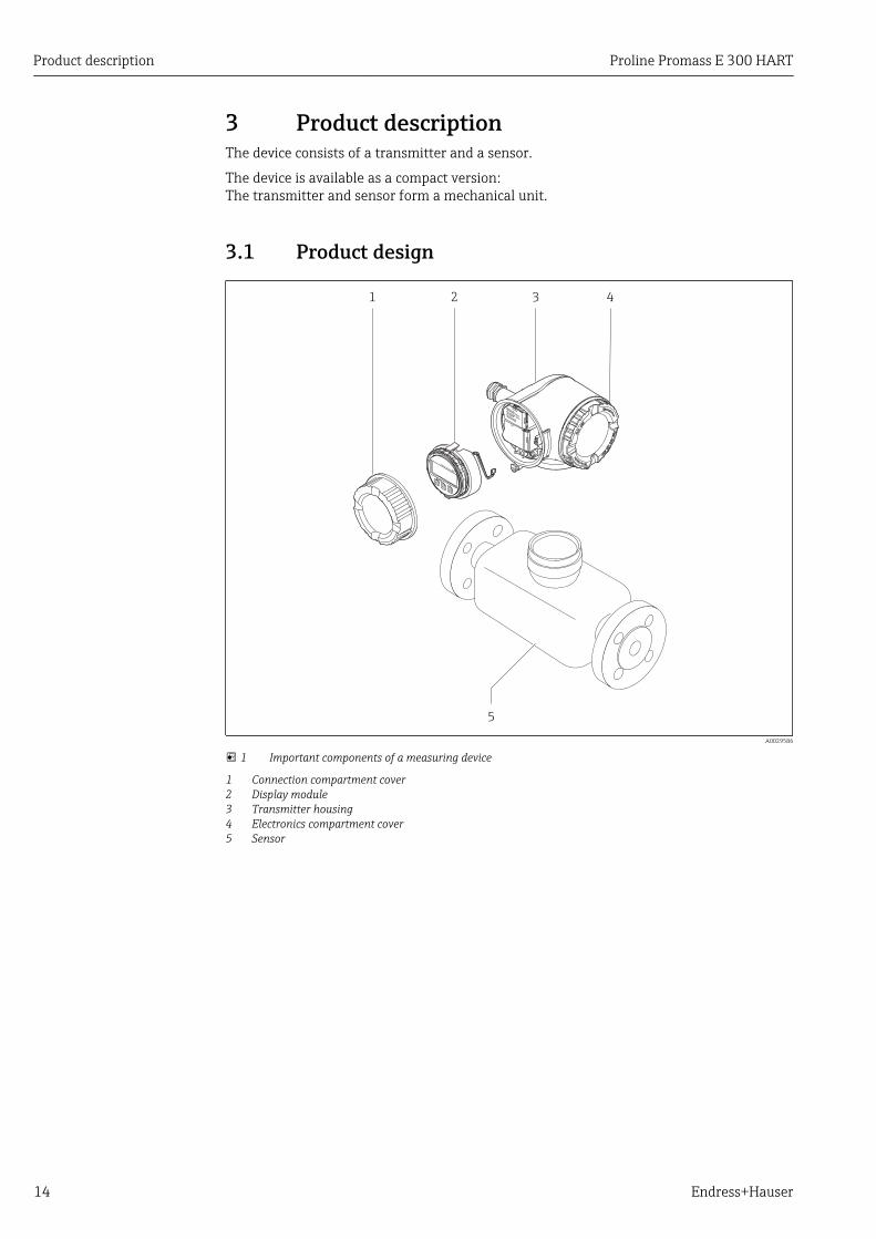
3 Product descriptionThe device consists of a transmitter and a sensor.
The device is available as a compact version:The transmitter and sensor form a mechanical unit.
3.1 Product design
5
4
Nicht unter
Spannung öffnen
Do not open when
energizedNe pas ouvrir
sous tension
Power
I/O
Nic
ht
unte
r
ar
e
öffn
en
Disp
lay
+
E
ESC
–
1 2 3
A0029586
1 Important components of a measuring device
1 Connection compartment cover2 Display module3 Transmitter housing4 Electronics compartment cover5 Sensor
Proline Promass E 300 HART Incoming acceptance and product identification
Endress+Hauser 15
4 Incoming acceptance and productidentification
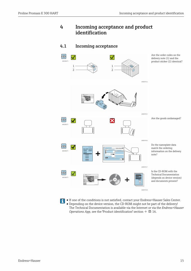
4.1 Incoming acceptance
A0028673
1
2
1
2
A0029314
Are the order codes on thedelivery note (1) and theproduct sticker (2) identical?
A0029315
A0028673
A0029316
Are the goods undamaged?
A0028673Order code:
Ser. no.:
Ext. ord. cd.:
i i
Date:
A0029317
Do the nameplate datamatch the orderinginformation on the deliverynote?
A0028673
A0029318
Is the CD-ROM with theTechnical Documentation(depends on device version)and documents present?
• If one of the conditions is not satisfied, contact your Endress+Hauser Sales Center.• Depending on the device version, the CD-ROM might not be part of the delivery!
The Technical Documentation is available via the Internet or via the Endress+HauserOperations App, see the "Product identification" section → 16.

Incoming acceptance and product identification Proline Promass E 300 HART
16 Endress+Hauser
4.2 Product identificationThe following options are available for identification of the measuring device:• Nameplate specifications• Order code with breakdown of the device features on the delivery note• Enter serial numbers from nameplates in W@M Device Viewer
(www.endress.com/deviceviewer): All information about the measuring device isdisplayed.
• Enter the serial number from the nameplates into the Endress+Hauser Operations Appor scan the 2-D matrix code (QR code) on the nameplate with the Endress+HauserOperations App: all the information for the measuring device is displayed.
For an overview of the scope of the associated Technical Documentation, refer to thefollowing:• The chapters "Additional standard documentation on the device" → 8 and
"Supplementary device-dependent documentation" → 8• The W@M Device Viewer: Enter the serial number from the nameplate
(www.endress.com/deviceviewer)• The Endress+Hauser Operations App: Enter the serial number from the nameplate or
scan the 2-D matrix code (QR code) on the nameplate.

Proline Promass E 300 HART Incoming acceptance and product identification
Endress+Hauser 17
4.2.1 Transmitter nameplate
Order code:
Ser. no.:
Ext. ord. cd.:
i i
Date:
1 2 3 4 5
20
19
6
7
8
9
13 12 1011
18
17
16
14
15
A0029192
2 Example of a transmitter nameplate
1 Manufacturing location2 Name of the transmitter3 Order code4 Serial number (ser. no.)5 Extended order code (Ext. ord. cd.)6 Degree of protection7 Space for approvals: use in hazardous areas8 Electrical connection data: available inputs and outputs9 2-D matrix code10 Manufacturing date: year-month11 Document number of safety-related supplementary documentation12 Space for approvals and certificates: e.g. CE mark, C-Tick13 Space for degree of protection of connection and electronics compartment when used in hazardous areas14 Firmware version (FW) and device revision (Dev.Rev.) from the factory15 Space for additional information in the case of special products16 Permitted temperature range for cable17 Permitted ambient temperature (Ta)18 Information on cable gland19 Available inputs and outputs, supply voltage20 Electrical connection data: supply voltage

Incoming acceptance and product identification Proline Promass E 300 HART
18 Endress+Hauser
4.2.2 Sensor nameplate
Order code:
Ser. no.:
Ext. ord. cd.:
1
678
2
3
5
4
A0029206
3 Example of a sensor nameplate, part 1
1 Name of the sensor2 Manufacturing location3 Nominal diameter of the sensor; flange nominal diameter/nominal pressure; sensor test pressure; medium
temperature range; material of measuring tube and manifold4 Sensor-specific information5 CE mark, C-Tick6 Order code7 Serial number (ser. no.)8 Extended order code (Ext. ord. cd.)
1
3
2
i i
Date:
4
56
A0029207
4 Example of a sensor nameplate, part 2
1 Approval information for explosion protection, Pressure Equipment Directive and degree of protection2 Permitted ambient temperature (Ta)3 Document number of safety-related supplementary documentation4 2-D matrix code5 Flow direction6 Manufacturing date: year-month
Order codeThe measuring device is reordered using the order code.
Extended order code• The device type (product root) and basic specifications (mandatory features) are
always listed.• Of the optional specifications (optional features), only the safety and approval-
related specifications are listed (e.g. LA). If other optional specifications are alsoordered, these are indicated collectively using the # placeholder symbol (e.g. #LA#).
• If the ordered optional specifications do not include any safety and approval-relatedspecifications, they are indicated by the + placeholder symbol (e.g. XXXXXX-ABCDE+).

Proline Promass E 300 HART Incoming acceptance and product identification
Endress+Hauser 19
4.2.3 Symbols on measuring device
Symbol Meaning
WARNING!This symbol alerts you to a dangerous situation. Failure to avoid this situation can result in seriousor fatal injury.
Reference to documentationRefers to the corresponding device documentation.
Protective ground connectionA terminal which must be connected to ground prior to establishing any other connections.

Storage and transport Proline Promass E 300 HART
20 Endress+Hauser
5 Storage and transport
5.1 Storage conditionsObserve the following notes for storage:• Store in the original packaging to ensure protection from shock.• Do not remove protective covers or protective caps installed on process connections.
They prevent mechanical damage to the sealing surfaces and contamination in themeasuring tube.
• Protect from direct sunlight to avoid unacceptably high surface temperatures.• Store in a dry and dust-free place.• Do not store outdoors.
Storage temperature: –50 to +80 °C (–58 to +176 °F),
5.2 Transporting the productTransport the measuring device to the measuring point in the original packaging.
A0029252
Do not remove protective covers or caps installed on process connections. Theyprevent mechanical damage to the sealing surfaces and contamination in themeasuring tube.
5.2.1 Measuring devices without lifting lugsLWARNING
Center of gravity of the measuring device is higher than the suspension points of thewebbing slings.Risk of injury if the measuring device slips.‣ Secure the measuring device against slipping or turning.‣ Observe the weight specified on the packaging (stick-on label).
A0029214

Proline Promass E 300 HART Storage and transport
Endress+Hauser 21
5.2.2 Measuring devices with lifting lugsLCAUTION
Special transportation instructions for devices with lifting lugs‣ Only use the lifting lugs fitted on the device or flanges to transport the device.‣ The device must always be secured at two lifting lugs at least.
5.2.3 Transporting with a fork liftIf transporting in wood crates, the floor structure enables the crates to be lifted lengthwiseor at both sides using a forklift.
5.3 Packaging disposalAll packaging materials are environmentally friendly and 100% recyclable:• Measuring device secondary packaging: polymer stretch film that conforms to EC
Directive 2002/95/EC (RoHS).• Packaging:
– Wood crate, treated in accordance with ISPM 15 standard, which is confirmed by theaffixed IPPC logo.or
– Carton in accordance with European Packaging Directive 94/62EC; recyclability isconfirmed by the affixed RESY symbol.
• Seaworthy packaging (optional): Wood crate, treated in accordance with ISPM 15standard, which is confirmed by the affixed IPPC logo.
• Carrying and mounting hardware:– Disposable plastic pallet– Plastic straps– Plastic adhesive strips
• Dunnage: Paper cushion
Installation Proline Promass E 300 HART
22 Endress+Hauser
6 Installation
6.1 Installation conditionsNo special measures such as supports are necessary. External forces are absorbed by theconstruction of the device.
6.1.1 Mounting position
Mounting location
A0028772
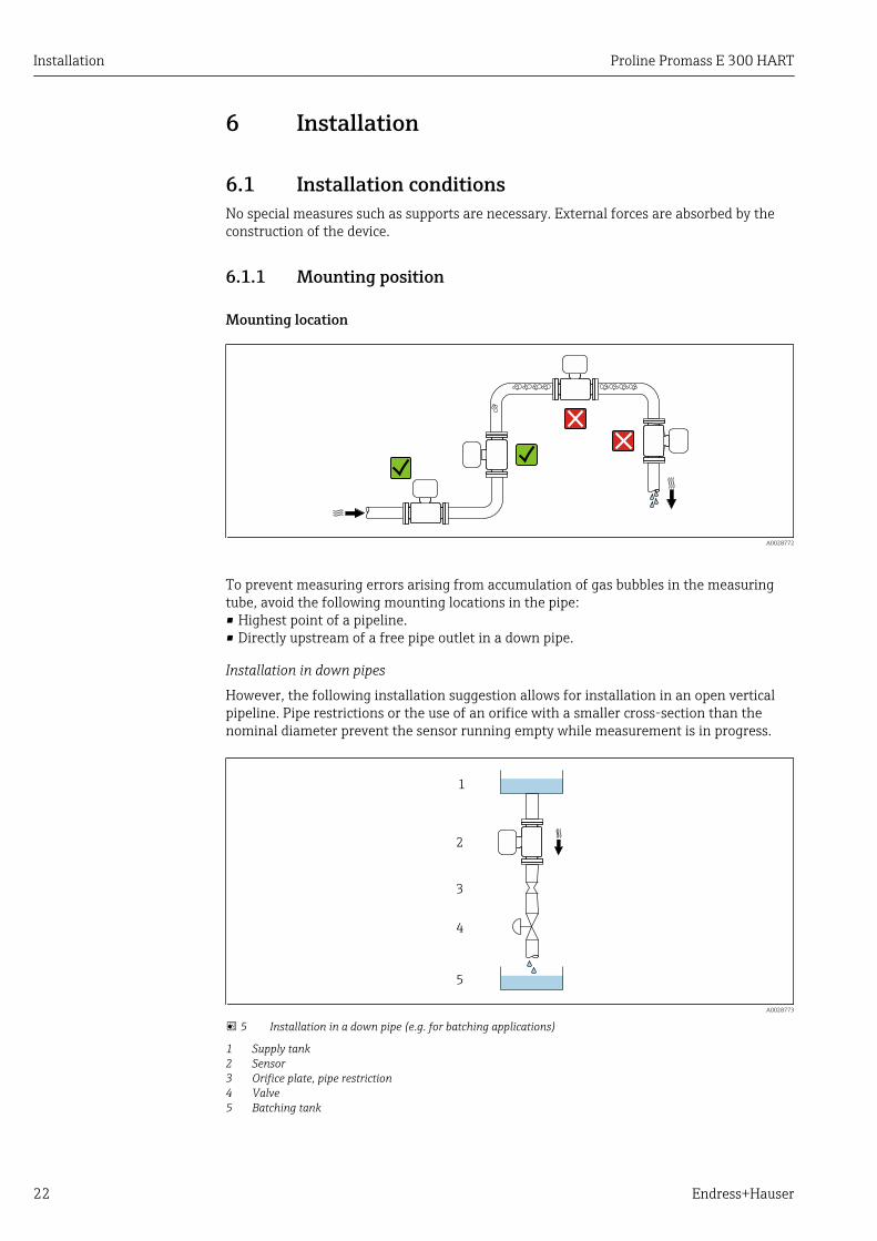
To prevent measuring errors arising from accumulation of gas bubbles in the measuringtube, avoid the following mounting locations in the pipe:• Highest point of a pipeline.• Directly upstream of a free pipe outlet in a down pipe.
Installation in down pipes
However, the following installation suggestion allows for installation in an open verticalpipeline. Pipe restrictions or the use of an orifice with a smaller cross-section than thenominal diameter prevent the sensor running empty while measurement is in progress.
1
2
3
4
5
A0028773
5 Installation in a down pipe (e.g. for batching applications)
1 Supply tank2 Sensor3 Orifice plate, pipe restriction4 Valve5 Batching tank
Proline Promass E 300 HART Installation
Endress+Hauser 23
DN Ø orifice plate, pipe restriction
[mm] [in] [mm] [in]
8 ³⁄₈ 6 0.24
15 ½ 10 0.40
25 1 14 0.55
40 1½ 22 0.87
50 2 28 1.10
80 3 50 1.97
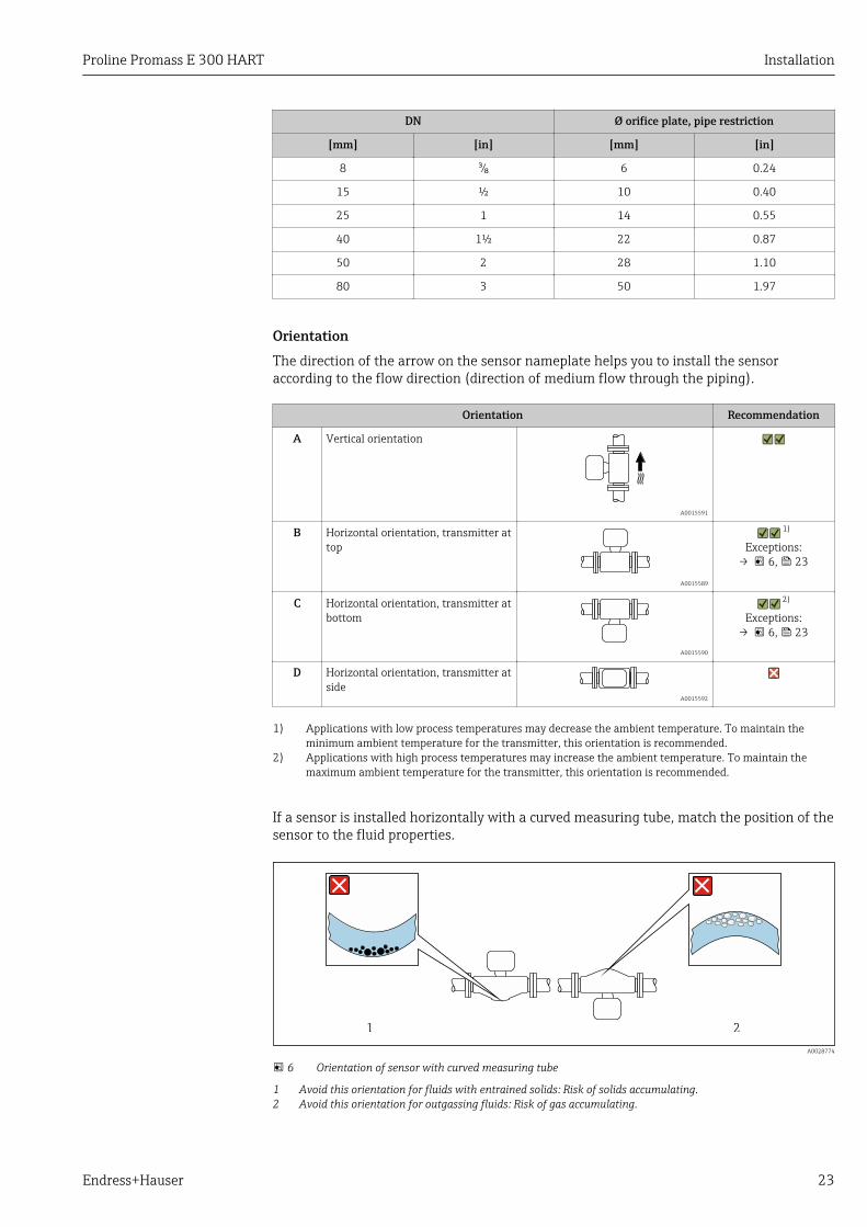
OrientationThe direction of the arrow on the sensor nameplate helps you to install the sensoraccording to the flow direction (direction of medium flow through the piping).
Orientation Recommendation
A Vertical orientation
A0015591
B Horizontal orientation, transmitter attop
A0015589
1)
Exceptions:→ 6, 23
C Horizontal orientation, transmitter atbottom
A0015590
2)
Exceptions:→ 6, 23
D Horizontal orientation, transmitter atside
A0015592
1) Applications with low process temperatures may decrease the ambient temperature. To maintain theminimum ambient temperature for the transmitter, this orientation is recommended.
2) Applications with high process temperatures may increase the ambient temperature. To maintain themaximum ambient temperature for the transmitter, this orientation is recommended.
If a sensor is installed horizontally with a curved measuring tube, match the position of thesensor to the fluid properties.
1 2
A0028774
6 Orientation of sensor with curved measuring tube
1 Avoid this orientation for fluids with entrained solids: Risk of solids accumulating.2 Avoid this orientation for outgassing fluids: Risk of gas accumulating.

Installation Proline Promass E 300 HART
24 Endress+Hauser
Inlet and outlet runsNo special precautions need to be taken for fittings which create turbulence, such asvalves, elbows or T-pieces, as long as no cavitation occurs → 24.
A0029322 A0029323
Installation dimensions
For the dimensions and installation lengths of the device, see the "TechnicalInformation" document, "Mechanical construction" section
6.1.2 Requirements from environment and process
Ambient temperature range
Measuring device Non-Ex –40 to +60 °C (–40 to +140 °F)
Ex ec, NI version –40 to +60 °C (–40 to +140 °F)
Ex ia, IS version • –40 to +60 °C (–40 to +140 °F)• Order code for "Test, certificate", option JP
–50 to +60 °C (–58 to +140 °F)
Readability of the local display –20 to +60 °C (–4 to +140 °F)The readability of the display may be impaired at temperatures outsidethe temperature range.
‣ If operating outdoors:Avoid direct sunlight, particularly in warm climatic regions.
You can order a weather protection cover from Endress+Hauser : → 155
System pressureIt is important that cavitation does not occur, or that gases entrained in the liquids do notoutgas.
Cavitation is caused if the pressure drops below the vapor pressure:• In liquids that have a low boiling point (e.g. hydrocarbons, solvents, liquefied gases)• In suction lines
‣ Ensure the system pressure is sufficiently high to prevent cavitation and outgassing.
For this reason, the following mounting locations are recommended:• At the lowest point in a vertical pipe• Downstream from pumps (no danger of vacuum)
A0028777
Proline Promass E 300 HART Installation
Endress+Hauser 25
Thermal insulationIn the case of some fluids, it is important that the heat radiated from the sensor to thetransmitter is kept to a minimum. A wide range of materials can be used for the requiredinsulation.
NOTICEElectronics overheating on account of thermal insulation!‣ Observe maximum permitted insulation height of the transmitter neck so that the
transmitter head is completely free.
NOTICEDanger of overheating with insulation‣ Ensure that the temperature at the lower end of the transmitter housing does not
exceed 80 °C (176 °F)
NOTICEThe insulation can also be thicker than the maximum recommended insulationthickness.Prerequisite:‣ Ensure that convection takes place on a sufficiently large scale at the transmitter neck.‣ Ensure that a sufficiently large area of the housing support remains exposed. The
uncovered part serves as a radiator and protects the electronics from overheating andexcessive cooling.
t
a
A0028853
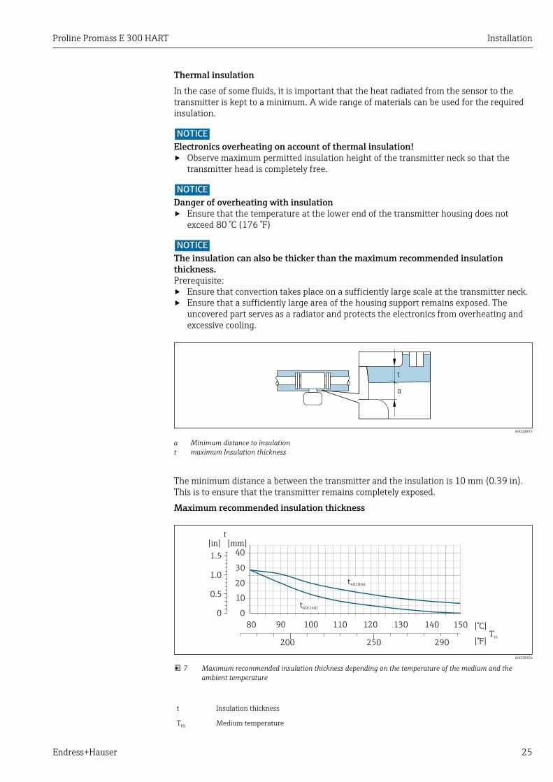
a Minimum distance to insulationt maximum Insulation thickness
The minimum distance a between the transmitter and the insulation is 10 mm (0.39 in).This is to ensure that the transmitter remains completely exposed.
Maximum recommended insulation thickness
0
10
30
20
40[ ]mm[ ]in
80 90 100 110 [°C]
[°F]200 250 290
0.5
1.0
1.5
0
t40(104)
t60(140)
t
120 130 140Tm
150
A0028904
7 Maximum recommended insulation thickness depending on the temperature of the medium and theambient temperature
t Insulation thickness
Tm Medium temperature

Installation Proline Promass E 300 HART
26 Endress+Hauser
t40(104) Maximum recommended insulation thickness at an ambient temperature of Ta = 40 °C (104 °F)
t60(140) Maximum recommended insulation thickness at an ambient temperature of Ta = 60 °C (140 °F)
HeatingNOTICE
Electronics can overheat due to elevated ambient temperature!‣ Observe maximum permitted ambient temperature for the transmitter .‣ Depending on the fluid temperature, take the device orientation requirements into
account .
NOTICEDanger of overheating when heating‣ Ensure that the temperature at the lower end of the transmitter housing does not
exceed 80 °C (176 °F).‣ Ensure that convection takes place on a sufficiently large scale at the transmitter neck.‣ Ensure that a sufficiently large area of the housing support remains exposed. The
uncovered part serves as a radiator and protects the electronics from overheating andexcessive cooling.
Heating options
If a fluid requires that no heat loss should occur at the sensor, users can avail of thefollowing heating options:• Electrical heating, e.g. with electric band heaters• Via pipes carrying hot water or steam• Via heating jackets
Using an electrical trace heating system
If heating is regulated via phase angle control or pulse packages, magnetic fields can affectthe measured values (= for values that are greater than the values permitted by the ENstandard (sine 30 A/m)).
For this reason, the sensor must be magnetically shielded: the housing can be shieldedwith tin plates or electric sheets without a privileged direction (e.g. V330-35A).
The sheet must have the following properties:• Relative magnetic permeability µr ≥ 300• Plate thickness d ≥ 0.35 mm (d ≥ 0.014 in)
VibrationsThe high oscillation frequency of the measuring tubes ensures that the correct operation ofthe measuring system is not influenced by plant vibrations.
6.1.3 Special mounting instructions
Rupture diskMake sure that the function and operation of the rupture disk is not impeded through theinstallation of the device. The position of the rupture disk is indicated on a sticker appliedover it. If the rupture disk is triggered, the sticker is destroyed. The disk can therefore bevisually monitored.
Information that is relevant to the process: → 174.

Proline Promass E 300 HART Installation
Endress+Hauser 27
RUPTURE DISK
i
1
DN 8 ( ")... ( ")!⁄# 50 2 DN ( ")80 3
A0029956
8 Rupture disk label
‣ After the rupture disk is actuated, do not operate the measuring device any more.
LWARNINGLimited functional reliability of the rupture disk.Danger to persons from escaping fluids!‣ Do not remove the rupture disk.‣ When using a rupture disk, do not use a heating jacket.‣ Make sure that the function and operation of the rupture disk is not impeded through
the installation of the device.‣ Take precautions to prevent damage and danger to persons if the rupture disk is
actuated.‣ Observe information on the rupture disk sticker.
Zero point adjustmentAll measuring devices are calibrated in accordance with state-of-the-art technology.Calibration takes place under reference conditions → 168. Therefore, a zero pointadjustment in the field is generally not required.
Experience shows that zero point adjustment is advisable only in special cases:• To achieve maximum measuring accuracy even with low flow rates• Under extreme process or operating conditions (e.g. very high process temperatures or
very high-viscosity fluids).
Protective cover
280 (11.0)
66
(2
.6)
270 (10.5)
A0029553
Installation Proline Promass E 300 HART
28 Endress+Hauser
6.2 Mounting the measuring device
6.2.1 Required tools
For sensorFor flanges and other process connections: Corresponding mounting tools
6.2.2 Preparing the measuring device1. Remove all remaining transport packaging.
2. Remove any protective covers or protective caps present from the sensor.
3. If present, remove transport protection of the rupture disk.
4. Remove stick-on label on the electronics compartment cover.
6.2.3 Mounting the measuring deviceLWARNING
Danger due to improper process sealing!‣ Ensure that the inside diameters of the gaskets are greater than or equal to that of the
process connections and piping.‣ Ensure that the gaskets are clean and undamaged.‣ Install the gaskets correctly.
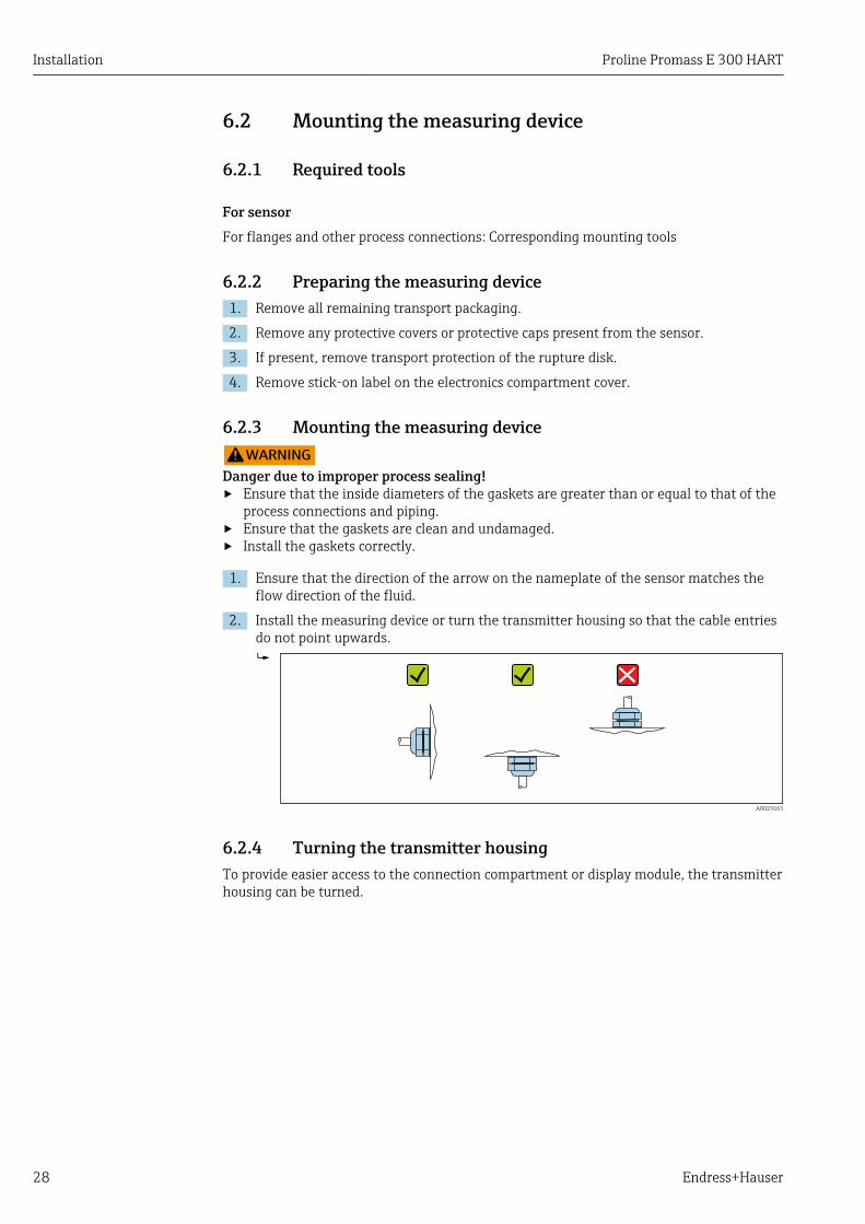
1. Ensure that the direction of the arrow on the nameplate of the sensor matches theflow direction of the fluid.
2. Install the measuring device or turn the transmitter housing so that the cable entriesdo not point upwards.
A0029263
6.2.4 Turning the transmitter housingTo provide easier access to the connection compartment or display module, the transmitterhousing can be turned.

Proline Promass E 300 HART Installation
Endress+Hauser 29
Nic
ht
unte
r
are
öffn
en
+
E
ESC
–
1.2.
Nic
ht
unte
r
are
öffn
en
+
E
ESC
–
3.3 mm 4 mm
4.
A0029993
1. Loosen the securing clamp of the connection compartment cover.
2. Unscrew the connection compartment cover.
3. Release the fixing screw.
4. Turn the housing to the desired position.
5. Firmly tighten the securing screw.
6. Screw on the connection compartment cover
7. Fit the securing clamp of the connection compartment cover.
6.2.5 Turning the display moduleThe display module can be turned to optimize display readability and operability.
Nic
ht
unte
r
are
öffn
en
+
E
ESC
–
1.2.
Nic
ht
unte
r
are
öffn
en
+
E
ESC
–
3.3 mm
+
E
ESC
–
A0030035
1. Loosen the securing clamp of the connection compartment cover.
2. Unscrew the connection compartment cover.
3. Turn the display module to the desired position: max. 8 × 45° in every direction.
4. Screw on the connection compartment cover.
5. Fit the securing clamp of the connection compartment cover.

Installation Proline Promass E 300 HART
30 Endress+Hauser
6.3 Post-installation check
Is the device undamaged (visual inspection)?
Does the measuring device conform to the measuring point specifications?
For example:• Process temperature → 173• Process pressure (refer to the chapter on "Pressure-temperature ratings" of the "Technical
Information" document)• Ambient temperature• Measuring range
Has the correct orientation for the sensor been selected ?
• According to sensor type• According to medium temperature• According to medium properties (outgassing, with entrained solids)
Does the arrow on the sensor nameplate match the direction of flow of the fluid through thepiping → 23?
Are the measuring point identification and labeling correct (visual inspection)?
Is the device adequately protected from precipitation and direct sunlight?
Are the securing screw and securing clamp tightened securely?
Proline Promass E 300 HART Electrical connection
Endress+Hauser 31
7 Electrical connectionNOTICE
The measuring device does not have an internal circuit breaker.‣ For this reason, assign the measuring device a switch or power-circuit breaker so that
the power supply line can be easily disconnected from the mains.‣ Although the measuring device is equipped with a fuse, additional overcurrent
protection (maximum 10 A) should be integrated into the system installation.
7.1 Connection conditions
7.1.1 Required tools• For cable entries: Use corresponding tools• For securing clamp: Allen key 3 mm• Wire stripper• When using stranded cables: Crimper for wire end ferrule• For removing cables from terminal: Flat blade screwdriver ≤ 3 mm (0.12 in)
7.1.2 Requirements for connecting cableThe connecting cables provided by the customer must fulfill the following requirements.
Electrical safetyIn accordance with applicable federal/national regulations.
Protective ground cableCable: 2.1 mm2 (14 AWG)
The grounding impedance must be less than 1 Ω.
Permitted temperature rangeMinimum requirement: cable temperature range ≥ ambient temperature +20 K
Power supply cableStandard installation cable is sufficient.
Signal cableCurrent output 4 to 20 mA HART
A shielded cable is recommended. Observe grounding concept of the plant.
Current output 0/4 to 20 mA
Standard installation cable is sufficient.
Pulse/frequency/switch output
Standard installation cable is sufficient.
Double pulse output
Standard installation cable is sufficient.
Relay output
Standard installation cable is sufficient.
Electrical connection Proline Promass E 300 HART
32 Endress+Hauser
Current input 0/4 to 20 mA
Standard installation cable is sufficient.
Status input
Standard installation cable is sufficient.
Cable diameter• Cable glands supplied:
M20 × 1.5 with cable 6 to 12 mm (0.24 to 0.47 in)• Spring terminals:
Conductor cross-section0.2 to 2.5 mm2 (24 to 12 AWG)
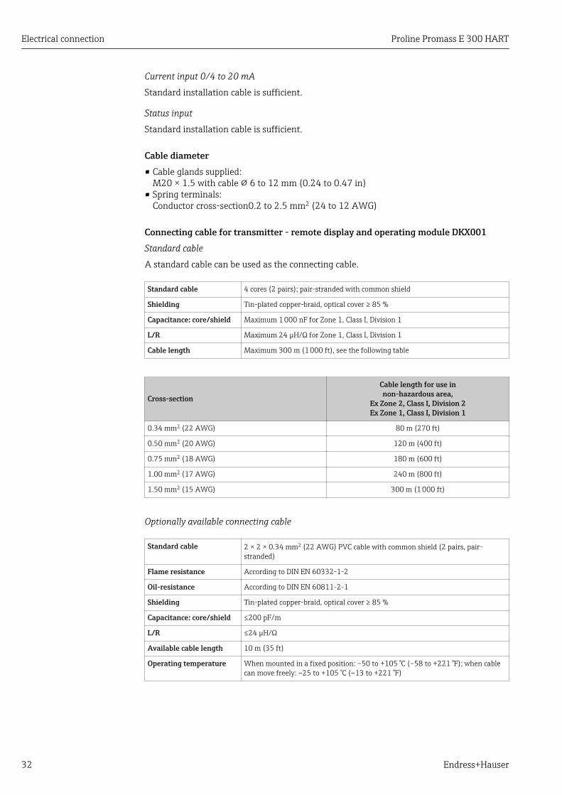
Connecting cable for transmitter - remote display and operating module DKX001Standard cable
A standard cable can be used as the connecting cable.
Standard cable 4 cores (2 pairs); pair-stranded with common shield
Shielding Tin-plated copper-braid, optical cover ≥ 85 %
Capacitance: core/shield Maximum 1 000 nF for Zone 1, Class I, Division 1
L/R Maximum 24 µH/Ω for Zone 1, Class I, Division 1
Cable length Maximum 300 m (1 000 ft), see the following table
Cross-section
Cable length for use innon-hazardous area,
Ex Zone 2, Class I, Division 2Ex Zone 1, Class I, Division 1
0.34 mm2 (22 AWG) 80 m (270 ft)
0.50 mm2 (20 AWG) 120 m (400 ft)
0.75 mm2 (18 AWG) 180 m (600 ft)
1.00 mm2 (17 AWG) 240 m (800 ft)
1.50 mm2 (15 AWG) 300 m (1 000 ft)
Optionally available connecting cable
Standard cable 2 × 2 × 0.34 mm2 (22 AWG) PVC cable with common shield (2 pairs, pair-stranded)
Flame resistance According to DIN EN 60332-1-2
Oil-resistance According to DIN EN 60811-2-1
Shielding Tin-plated copper-braid, optical cover ≥ 85 %
Capacitance: core/shield ≤200 pF/m
L/R ≤24 µH/Ω
Available cable length 10 m (35 ft)
Operating temperature When mounted in a fixed position: –50 to +105 °C (–58 to +221 °F); when cablecan move freely: –25 to +105 °C (–13 to +221 °F)

Proline Promass E 300 HART Electrical connection
Endress+Hauser 33
7.1.3 Terminal assignment
Transmitter: supply voltage, input/outputsThe terminal assignment of the inputs and outputs depends on the individual orderversion of the device. The device-specific terminal assignment is documented on anadhesive label in the terminal cover.
Supply voltage Input/output 1 Input/output 2 Input/output 3
1 (+) 2 (–) 26 (+) 27 (–) 24 (+) 25 (–) 22 (+) 23 (–)
Device-specific terminal assignment: adhesive label in terminal cover.
Terminal assignment of the remote display and operating module: → 36
7.1.4 Preparing the measuring deviceNOTICE
Insufficient sealing of the housing!Operational reliability of the measuring device could be compromised.‣ Use suitable cable glands corresponding to the degree of protection.
1. Remove dummy plug if present.
2. If the measuring device is supplied without cable glands:Provide suitable cable gland for corresponding connecting cable.
3. If the measuring device is supplied with cable glands:Observe requirements for connecting cables → 31.
7.2 Connecting the measuring deviceNOTICE
Limitation of electrical safety due to incorrect connection!‣ Have electrical connection work carried out by correspondingly trained specialists only.‣ Observe applicable federal/national installation codes and regulations.‣ Comply with local workplace safety regulations.‣ Always connect the protective ground cable before connecting additional cables.‣ For use in potentially explosive atmospheres, observe the information in the device-
specific Ex documentation.
7.2.1 Connecting the transmitter
1
2
3
A0026781
1 Cable entry for supply voltage2 Cable entry for signal transmission, input/output 1 and 23 Cable entry for input/output signal transmission; Optional: connection of external WLAN antenna,
connection of remote display and operating module DKX001 or service plug
Electrical connection Proline Promass E 300 HART
34 Endress+Hauser
Nic
ht
unte
r
ar
e
öffn
en
+
E
ESC
–
1.2.
Nic
ht
unte
r
ar
e
öffn
en
+
E
ESC
–
+
E
ESC
–
3.
3.
4.
3 mm
A0029813
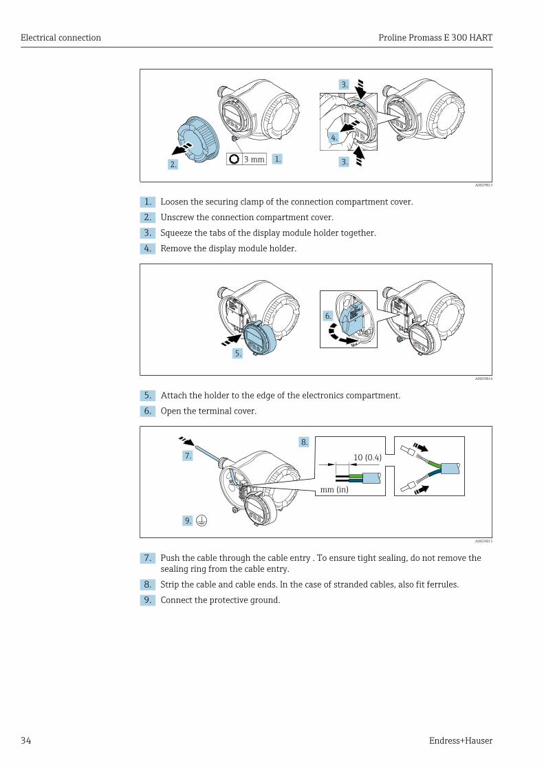
1. Loosen the securing clamp of the connection compartment cover.
2. Unscrew the connection compartment cover.
3. Squeeze the tabs of the display module holder together.
4. Remove the display module holder.
Nic
ht
unte
r
ar
e
öffnen
Nicht unter
Spannung öffnen
Do not open when
energizedNe pas ouvrir
sous tension
Power
I/O
+
E
ESC
–
5.
Nic
ht
unte
r
ar
e
öffnen
Nicht unter
Spannung öffnen
Do not open when
energizedNe pas ouvrir
sous tension
Power
I/O
+
E
ESC
–
Power
Nicht unter
Spannung öffnen
Do not open w
hen
energized
Ne pas ouvrir
sous tension
I/O
6.
A0029814
5. Attach the holder to the edge of the electronics compartment.
6. Open the terminal cover.
Nic
ht
unte
r
ar
e
öffn
en
+
E
ESC
–
10 (0.4)
mm (in)
7.
8.
9.
A0029815
7. Push the cable through the cable entry . To ensure tight sealing, do not remove thesealing ring from the cable entry.
8. Strip the cable and cable ends. In the case of stranded cables, also fit ferrules.
9. Connect the protective ground.
Proline Promass E 300 HART Electrical connection
Endress+Hauser 35
Nic
ht
unte
r
ar
e
öffn
en
+
E
ESC
–
10.
11.
22 mm
24 mm
A0029816
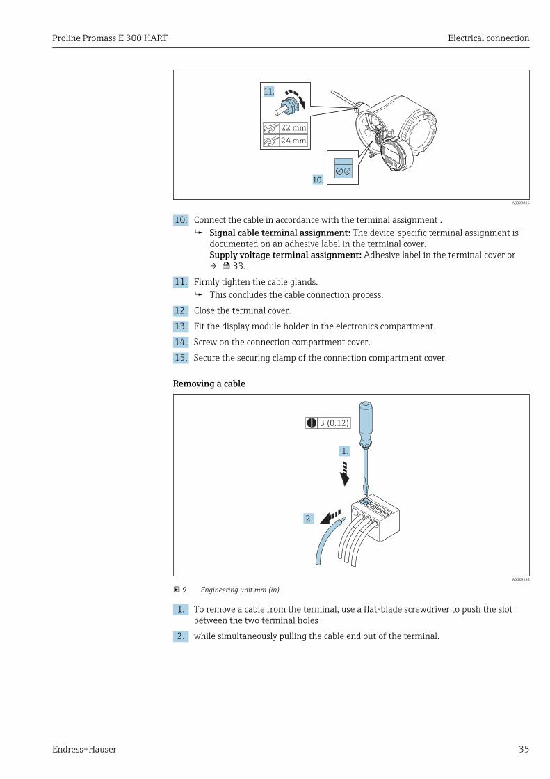
10. Connect the cable in accordance with the terminal assignment . Signal cable terminal assignment: The device-specific terminal assignment is
documented on an adhesive label in the terminal cover.Supply voltage terminal assignment: Adhesive label in the terminal cover or→ 33.
11. Firmly tighten the cable glands. This concludes the cable connection process.
12. Close the terminal cover.
13. Fit the display module holder in the electronics compartment.
14. Screw on the connection compartment cover.
15. Secure the securing clamp of the connection compartment cover.
Removing a cable
3 (0.12)
2.
1.
A0029598
9 Engineering unit mm (in)
1. To remove a cable from the terminal, use a flat-blade screwdriver to push the slotbetween the two terminal holes
2. while simultaneously pulling the cable end out of the terminal.
Electrical connection Proline Promass E 300 HART
36 Endress+Hauser
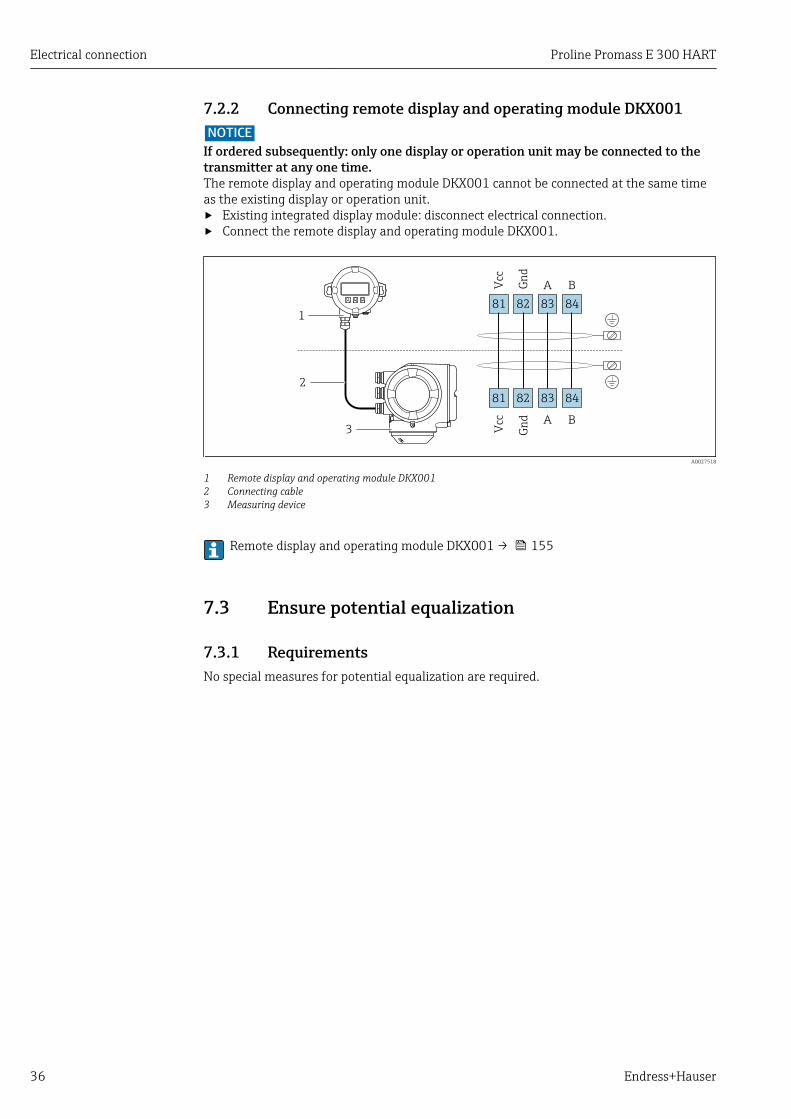
7.2.2 Connecting remote display and operating module DKX001NOTICE
If ordered subsequently: only one display or operation unit may be connected to thetransmitter at any one time.The remote display and operating module DKX001 cannot be connected at the same timeas the existing display or operation unit.‣ Existing integrated display module: disconnect electrical connection.‣ Connect the remote display and operating module DKX001.
1
2
3
81
Vcc
82
Gn
d
83
A
84
B
81
Vcc
82
Gn
d
83
A
84
B
A0027518
1 Remote display and operating module DKX0012 Connecting cable3 Measuring device
Remote display and operating module DKX001 → 155
7.3 Ensure potential equalization
7.3.1 RequirementsNo special measures for potential equalization are required.

Proline Promass E 300 HART Electrical connection
Endress+Hauser 37
7.4 Special connection instructions
7.4.1 Connection examples
Current output 4 to 20 mA HART
4
4...20 mA
5
21 3
6
A0029055
10 Connection example for 4 to 20 mA HART current output (active)
1 Automation system with current input (e.g. PLC)2 Cable shield: the cable shield must be grounded at both ends to comply with EMC requirements; observe cable
specifications3 Connection for HART operating devices → 624 Resistor for HART communication (≥ 250 Ω): observe maximum load → 1625 Analog display unit: observe maximum load → 1626 Transmitter
2 3
4...20 mA
41
5
A0028762
11 Connection example for 4 to 20 mA HART current output (passive)
1 Automation system with current input (e.g. PLC)2 Power supply3 Cable shield: the cable shield must be grounded at both ends to comply with EMC requirements; observe cable
specifications4 Analog display unit: observe maximum load → 1625 Transmitter

Electrical connection Proline Promass E 300 HART
38 Endress+Hauser
HART input
2
4...20 mA
41
2
3
3
6
5
A0028763
12 Connection example for HART input with a common negative (passive)
1 Automation system with HART output (e.g. PLC)2 Active barrier for power supply (e.g. RN221N)3 Cable shield: the cable shield must be grounded at both ends to comply with EMC requirements; observe cable
specifications4 Analog display unit: observe maximum load5 Pressure transmitter (e.g. Cerabar M, Cerabar S): see requirements6 Transmitter
Current output 4-20 mA
4...20 mA
21
3
A0028758
13 Connection example for 4-20 mA current output (active)
1 Automation system with current input (e.g. PLC)2 Analog display unit: observe maximum load3 Transmitter
2
4...20 mA
31
4
A0028759
14 Connection example for 4-20 mA current output (passive)
1 Automation system with current input (e.g. PLC)2 Active barrier for power supply (e.g. RN221N)3 Analog display unit: observe maximum load4 Transmitter

Proline Promass E 300 HART Electrical connection
Endress+Hauser 39
Pulse/frequency output
1 2
3
12345
A0028761
15 Connection example for pulse/frequency output (passive)
1 Automation system with pulse/frequency input (e.g. PLC)2 Power supply3 Transmitter: Observe input values → 162
Switch output
1 2
3
A0028760
16 Connection example for switch output (passive)
1 Automation system with switch input (e.g. PLC)2 Power supply3 Transmitter: Observe input values → 162
Double pulse output
1
2
3
4
A0029280
17 Connection example for double pulse output (active)
1 Automation system with double pulse input (e.g. PLC)2 Transmitter: Observe input values → 1643 Double pulse output4 Double pulse output (slave), phase-shifted

Electrical connection Proline Promass E 300 HART
40 Endress+Hauser
1
3
2
4
5
A0029279
18 Connection example for double pulse output (passive)
1 Automation system with double pulse input (e.g. PLC)2 Power supply3 Transmitter: Observe input values → 1644 Double pulse output5 Double pulse output (slave), phase-shifted
Relay output
1 2
3
A0028760
19 Connection example for relay output (passive)
1 Automation system with relay input (e.g. PLC)2 Power supply3 Transmitter: Observe input values → 164
Current input
21
3
A0028915
20 Connection example for 4 to 20 mA current input
1 Power supply2 External measuring device (for reading in pressure or temperature, for instance)3 Transmitter: Observe input values

Proline Promass E 300 HART Electrical connection
Endress+Hauser 41
Status input
1 2
3
A0028764
21 Connection example for status input
1 Automation system with status output (e.g. PLC)2 Power supply3 Transmitter: Observe input values
7.5 Ensuring the degree of protectionThe measuring device fulfills all the requirements for the IP66/67 degree of protection,Type 4X enclosure.
To guarantee IP66/67 degree of protection, Type 4X enclosure, carry out the followingsteps after the electrical connection:
1. Check that the housing seals are clean and fitted correctly.
2. Dry, clean or replace the seals if necessary.
3. Tighten all housing screws and screw covers.
4. Firmly tighten the cable glands.
5. To ensure that moisture does not enter the cable entry:Route the cable so that it loops down before the cable entry ("water trap").
A0029278
6. Insert dummy plugs into unused cable entries.
7.6 Post-connection check
Are cables or the device undamaged (visual inspection)?
Do the cables used meet the requirements?
Do the cables have adequate strain relief?
Are all the cable glands installed, firmly tightened and leak-tight? Cable run with "water trap"→ 41 ?
If supply voltage is present, do values appear on the display module?

Operation options Proline Promass E 300 HART
42 Endress+Hauser
8 Operation options
8.1 Overview of operation options
1 2 3 4 5
E+-
ESC
6
A0029295
1 Local operation via display module2 Computer with Web browser (e.g. Internet Explorer) or with operating tool (e.g. FieldCare, DeviceCare, AMS
Device Manager, SIMATIC PDM)3 Field Xpert SFX350 or SFX3704 Field Communicator 4755 Mobile handheld terminal6 Control system (e.g. PLC)

Proline Promass E 300 HART Operation options
Endress+Hauser 43
8.2 Structure and function of the operating menu
8.2.1 Structure of the operating menuFor an overview of the operating menu for experts: "Description of Device Parameters"document supplied with the device→ 186
!
Expert
System
Sensor
Communication
Application
Diagnostics
Access status display
Output
Operating menu for experts
Language
Operatation Language
Parameter 1
Setup
Submenu 1
Submenu n
Device tag
Advanced setup Enter access code
Parameter 1
Parameter n
Submenu 1
Submenu n
Diagnostics Parameter 1
Parameter n
Submenu 1
Submenu n
Operating menu for operators and maintenances
Parameter n
Op
era
tor
Ma
inte
na
nce
Ta
sk-o
rie
nte
dF
un
ctio
n-o
rie
nte
d
Ex
pe
rt
Wizard 1 / Parameter 1
Wizard n / Parameter n
Parameter n
Input
A0018237-EN
22 Schematic structure of the operating menu

Operation options Proline Promass E 300 HART
44 Endress+Hauser
8.2.2 Operating philosophyThe individual parts of the operating menu are assigned to certain user roles (operator,maintenance etc.). Each user role contains typical tasks within the device lifecycle.
Menu/parameter User role and tasks Content/meaning
Language task-oriented Role "Operator", "Maintenance"Tasks during operation:• Configuring the operational
display• Reading measured values
• Defining the operating language• Defining the Web server operating language• Resetting and controlling totalizers
Operation • Configuring the operational display (e.g. display format, display contrast)• Resetting and controlling totalizers
Setup "Maintenance" roleCommissioning:• Configuration of the
measurement• Configuration of the inputs and
outputs• Configuration of the
communication interface
Wizards for fast commissioning:• Set the system units• Configuration of the communication interface• Define the medium• Display I/O/configuration• Configure the inputs• Configure the outputs• Configuring the operational display• Define the output conditioning• Set the low flow cut off• Configure partial and empty pipe detection
Advanced setup• For more customized configuration of the measurement (adaptation to
special measuring conditions)• Configuration of totalizers• Configure the WLAN settings• Administration (define access code, reset measuring device)
Diagnostics "Maintenance" roleFault elimination:• Diagnostics and elimination of
process and device errors• Measured value simulation
Contains all parameters for error detection and analyzing process and deviceerrors:• Diagnostic list
Contains up to 5 currently pending diagnostic messages.• Event logbook
Contains event messages that have occurred.• Device information
Contains information for identifying the device.• Measured values
Contains all current measured values.• Data logging submenu with "Extended HistoROM" order option
Storage and visualization of measured values• Heartbeat
The functionality of the device is checked on demand and the verificationresults are documented.
• SimulationIs used to simulate measured values or output values.
Expert function-oriented Tasks that require detailedknowledge of the function of thedevice:• Commissioning measurements
under difficult conditions• Optimal adaptation of the
measurement to difficultconditions
• Detailed configuration of thecommunication interface
• Error diagnostics in difficult cases
Contains all the parameters of the device and makes it possible to accessthese parameters directly using an access code. The structure of this menu isbased on the function blocks of the device:• System
Contains all higher-order device parameters which do not concern themeasurement or the communication interface.
• SensorConfiguration of the measurement.
• InputConfiguring the status input.
• OutputConfiguring of the analog current outputs as well as the pulse/frequencyand switch output.
• CommunicationConfiguration of the digital communication interface and the Web server.
• ApplicationConfigure the functions that go beyond the actual measurement (e.g.totalizer).
• DiagnosticsError detection and analysis of process and device errors and for devicesimulation and Heartbeat Technology.
Proline Promass E 300 HART Operation options
Endress+Hauser 45
8.3 Access to the operating menu via the local display
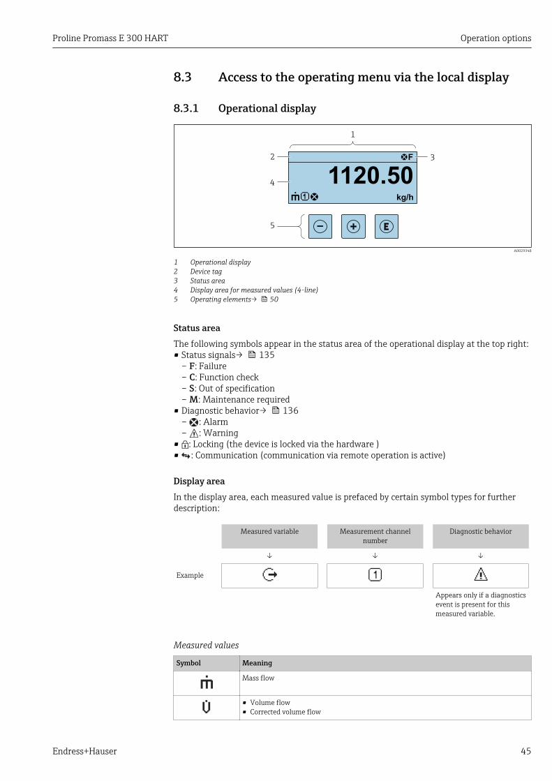
8.3.1 Operational display
X X X X X X XX X
4
2
1
3
5
kg/h
1120.50F
A0029348
1 Operational display2 Device tag3 Status area4 Display area for measured values (4-line)5 Operating elements→ 50
Status areaThe following symbols appear in the status area of the operational display at the top right:• Status signals→ 135
– F: Failure– C: Function check– S: Out of specification– M: Maintenance required
• Diagnostic behavior→ 136– : Alarm– : Warning
• : Locking (the device is locked via the hardware )• : Communication (communication via remote operation is active)
Display areaIn the display area, each measured value is prefaced by certain symbol types for furtherdescription:
Measured variable Measurement channelnumber
Diagnostic behavior
↓ ↓ ↓
Example
Appears only if a diagnosticsevent is present for thismeasured variable.
Measured values
Symbol Meaning
Mass flow
• Volume flow• Corrected volume flow
Operation options Proline Promass E 300 HART
46 Endress+Hauser
• Density• Reference density
Temperature
Totalizer
The measurement channel number indicates which of the three totalizers isdisplayed.
Output
The measurement channel number indicates which of the outputs is displayed.
Status input
Measurement channel numbers
Symbol Meaning
Measurement channel 1 to 4
The measurement channel number is displayed only if more than one channel is present for the same measuredvariable type (e.g. Totalizer 1 to 3).
Diagnostic behavior
The diagnostic behavior pertains to a diagnostic event that is relevant to the displayed measured variable.For information on the symbols → 136
The number and display format of the measured values can be configured via the"Format display" parameter → 97. Operation → Display → Format display
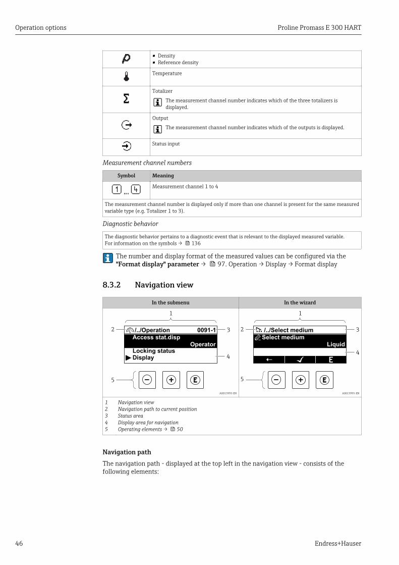
8.3.2 Navigation view
In the submenu In the wizard
4
2
1
3
5
/../Operation 0091-1
Access stat.dispOperator
Locking statusDisplay
A0013993-EN
4
2
1
5
3/../Select medium
Select medium
Liquid
A0013995-EN
12345
Navigation viewNavigation path to current positionStatus areaDisplay area for navigationOperating elements → 50
Navigation pathThe navigation path - displayed at the top left in the navigation view - consists of thefollowing elements:
Proline Promass E 300 HART Operation options
Endress+Hauser 47
• In the submenu:Display symbol for menu
• In the wizard:Display symbol for wizard
Omission symbol foroperating menu levels inbetween
Name of current• Submenu• Wizard• Parameters
↓ ↓ ↓
Examples / ../ Display
/ ../ Display
For more information about the icons in the menu, refer to the "Display area" section→ 47
Status areaThe following appears in the status area of the navigation view in the top right corner:• In the submenu
– The direct access code for the parameter you are navigating to (e.g. 0022-1)– If a diagnostic event is present, the diagnostic behavior and status signal
• In the wizardIf a diagnostic event is present, the diagnostic behavior and status signal
• For information on the diagnostic behavior and status signal → 135• For information on the function and entry of the direct access code → 52
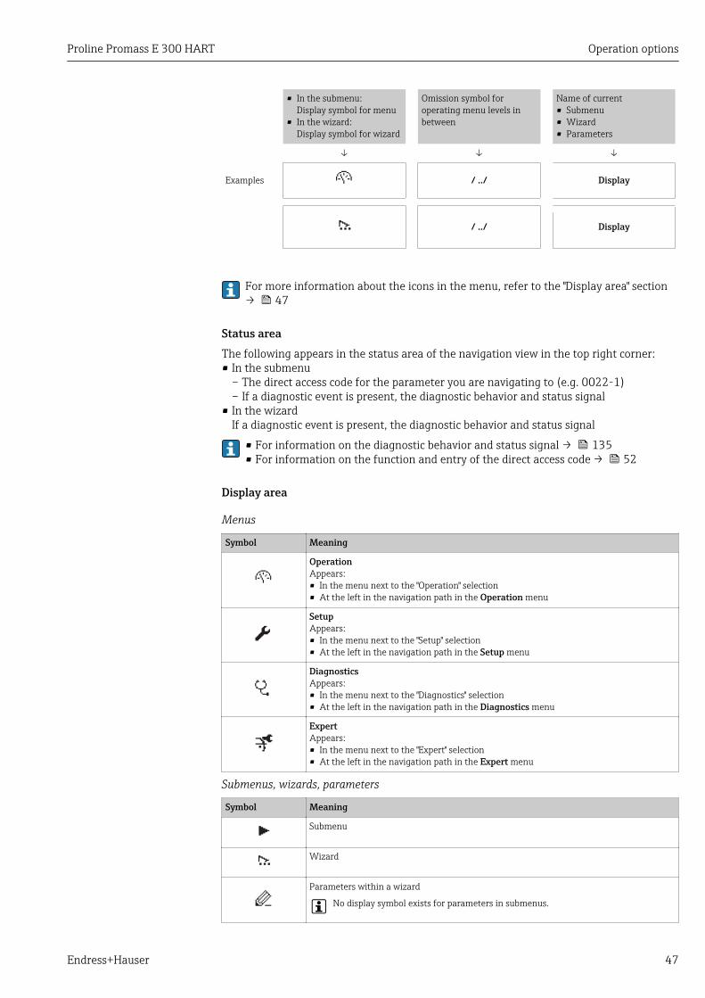
Display area
Menus
Symbol Meaning
OperationAppears:• In the menu next to the "Operation" selection• At the left in the navigation path in the Operation menu
SetupAppears:• In the menu next to the "Setup" selection• At the left in the navigation path in the Setup menu
DiagnosticsAppears:• In the menu next to the "Diagnostics" selection• At the left in the navigation path in the Diagnostics menu
ExpertAppears:• In the menu next to the "Expert" selection• At the left in the navigation path in the Expert menu
Submenus, wizards, parameters
Symbol Meaning
Submenu
Wizard
Parameters within a wizard
No display symbol exists for parameters in submenus.
Operation options Proline Promass E 300 HART
48 Endress+Hauser
Locking
Symbol Meaning
Parameter lockedWhen displayed in front of a parameter name, indicates that the parameter is locked.• By a user-specific access code• By the hardware write protection switch
Wizard operation
Symbol Meaning
Switches to the previous parameter.
Confirms the parameter value and switches to the next parameter.
Opens the editing view of the parameter.
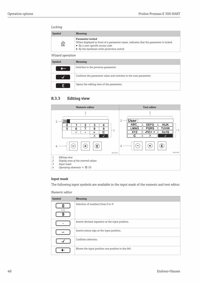
8.3.3 Editing view
Numeric editor Text editor
3
2
1
4
3 40 1 2
95 6 87
20
A0013941
ABC_ DEFG
UserHIJK
LMNO PQRS TUVW
XYZ Aa13
2
1
4
A0013999
1234
Editing viewDisplay area of the entered valuesInput maskOperating elements → 50
Input maskThe following input symbols are available in the input mask of the numeric and text editor:
Numeric editor
Symbol Meaning
…0
9
Selection of numbers from 0 to 9.
.
Inserts decimal separator at the input position.
–
Inserts minus sign at the input position.
Confirms selection.
Moves the input position one position to the left.
Proline Promass E 300 HART Operation options
Endress+Hauser 49
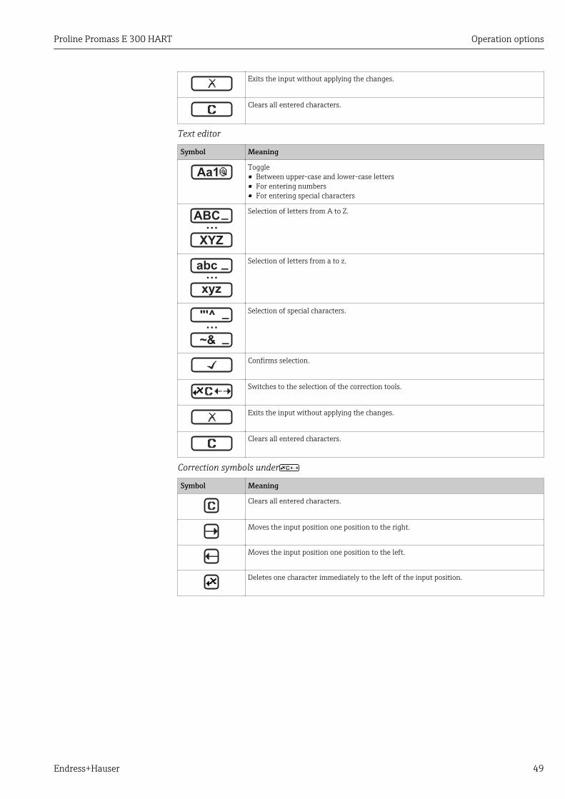
Exits the input without applying the changes.
Clears all entered characters.
Text editor
Symbol Meaning
Aa1Toggle• Between upper-case and lower-case letters• For entering numbers• For entering special characters
XYZ
ABC_…
Selection of letters from A to Z.
xyz
abc _…
Selection of letters from a to z.
~&
"'^ _…
_
Selection of special characters.
Confirms selection.
Switches to the selection of the correction tools.
Exits the input without applying the changes.
Clears all entered characters.
Correction symbols under
Symbol Meaning
Clears all entered characters.
Moves the input position one position to the right.
Moves the input position one position to the left.
Deletes one character immediately to the left of the input position.

Operation options Proline Promass E 300 HART
50 Endress+Hauser
8.3.4 Operating elements
Key Meaning
Minus key
In a menu, submenuMoves the selection bar upwards in a choose list.
With a WizardConfirms the parameter value and goes to the previous parameter.
With a text and numeric editorIn the input mask, moves the selection bar to the left (backwards).
Plus key
In a menu, submenuMoves the selection bar downwards in a choose list.
With a WizardConfirms the parameter value and goes to the next parameter.
With a text and numeric editorMoves the selection bar to the right (forwards) in an input screen.
Enter key
For operational display• Pressing the key briefly opens the operating menu.• Pressing the key for 2 s opens the context menu.
In a menu, submenu• Pressing the key briefly:
– Opens the selected menu, submenu or parameter.– Starts the wizard.– If help text is open, closes the help text of the parameter.
• Pressing the key for 2 s for parameter:If present, opens the help text for the function of the parameter.
With a WizardOpens the editing view of the parameter.
With a text and numeric editor• Pressing the key briefly:
– Opens the selected group.– Carries out the selected action.
• Pressing the key for 2 s confirms the edited parameter value.
+
Escape key combination (press keys simultaneously)
In a menu, submenu• Pressing the key briefly:
– Exits the current menu level and takes you to the next higher level.– If help text is open, closes the help text of the parameter.
• Pressing the key for 2 s returns you to the operational display ("home position").
With a WizardExits the wizard and takes you to the next higher level.
With a text and numeric editorCloses the text or numeric editor without applying changes.
+Minus/Enter key combination (press the keys simultaneously)
Reduces the contrast (brighter setting).
+Plus/Enter key combination (press and hold down the keys simultaneously)
Increases the contrast (darker setting).
++
Minus/Plus/Enter key combination (press the keys simultaneously)
For operational displayEnables or disables the keypad lock (only SD02 display module).
8.3.5 Opening the context menuUsing the context menu, the user can call up the following menus quickly and directly fromthe operational display:

Proline Promass E 300 HART Operation options
Endress+Hauser 51
• Setup• Data backup• Simulation
Calling up and closing the context menuThe user is in the operational display.
1. Press for 2 s. The context menu opens.
XXXXXXXXXX
l/h
20.50Setup
Simulation
A0017421-EN
2. Press + simultaneously. The context menu is closed and the operational display appears.
Calling up the menu via the context menu1. Open the context menu.
2. Press to navigate to the desired menu.
3. Press to confirm the selection. The selected menu opens.

Operation options Proline Promass E 300 HART
52 Endress+Hauser
8.3.6 Navigating and selecting from listDifferent operating elements are used to navigate through the operating menu. Thenavigation path is displayed on the left in the header. Icons are displayed in front of theindividual menus. These icons are also shown in the header during navigation.
For an explanation of the navigation view with symbols and operating elements→ 46
Example: Setting the number of displayed measured values to "2 values"
X X X X X X XX X
20.500104-1
2 s
0091-1
0098-1
0098-1
0098-1
X X X X X X XX X10.50
2800
Hz
mA
3.
4.
5.
6.
7.
8.
1.
2. Display/operat.
Display/operat.
Setup
Main menu
English
Main menu
Format display
/ ../Display
Contrast displayDisplay intervall
1 value, max.
Setup
Access stat.disp
/ ../Display/operat.
Display
Locking status
1 value, max.
/ ../Format display
2 valuesVal. large+2val.
Bargr. + 1 value
Locking status
/ ../Display/operat.
Display
1 value, max.
/ ../Format display
2 values
Val. large+2val.
Bargr. + 1 value
Operator
Language
Language
A0029562-EN
8.3.7 Calling the parameter directlyA parameter number is assigned to every parameter to be able to access a parameterdirectly via the onsite display. Entering this access code in the Direct access parametercalls up the desired parameter directly.
Navigation pathExpert → Direct access

Proline Promass E 300 HART Operation options
Endress+Hauser 53
The direct access code consists of a 4-digit number and the channel number, whichidentifies the channel of a process variable: e.g. 0914-1. In the navigation view, thisappears on the right-hand side in the header of the selected parameter.
10914-2
A0029414
1 Direct access code
Note the following when entering the direct access code:• The leading zeros in the direct access code do not have to be entered.
Example: Input of "914" instead of "0914"• If no channel number is entered, channel 1 is jumped to automatically.
Example: Enter 0914 → Assign process variable parameter• If a different channel is jumped to: Enter the direct access code with the corresponding
channel number.Example: Enter 0914-2 → Assign process variable parameter
For the direct access codes of the individual parameters, see the "Description of DeviceParameters" document for the device
8.3.8 Calling up help textHelp text is available for some parameters and can be called up from the navigation view.The help text provides a brief explanation of the parameter function and thereby supportsswift and safe commissioning.
Calling up and closing the help textThe user is in the navigation view and the selection bar is on a parameter.
1. Press for 2 s. The help text for the selected parameter opens.
Ent. access code
Enter access code to disable
write protec.
A0014002-EN
23 Example: Help text for parameter "Enter access code"
2. Press + simultaneously. The help text is closed.

Operation options Proline Promass E 300 HART
54 Endress+Hauser
8.3.9 Changing the parametersFor a description of the editing display - consisting of text editor and numeric editor -with symbols → 48, for a description of the operating elements → 50
Example: Changing the tag name in the "Tag description" parameter from 001-FT-101 to001-FT-102
3x
001-FT-101
DEFG HIJK
LMNO PQRS TUVW
XYZ Aa1@
ABC
001-FT-101
DEFG HIJK
LMNO PQRS TUVW
XYZ Aa1@
ABC
001-FT-101
DEFG HIJKABC
001-FT-10
DEFG HIJKABC
001-FT-10
DEFG HIJKABC
1x
001-FT-10
DEFG HIJK
LMNO PQRS TUVW
XYZ Aa1@
ABC
001-FT-10
DEFG HIJK
LMNO PQRS TUVW
XYZ Aa1@
ABC
001-FT-10
DEFG HIJKABC
A a 1 @
001-FT-10
DEFG HIJKABC
A a 1 @
001-FT-10
3456 789
= + - * / [ ] ( )
< > Aa1@
012
001-FT-10
3456 789012
0 1 2
001-FT-10
3456 789012
0 1 2
001-FT-102
3456 789012
0 1 2
001-FT-102
3456 789
= + - * / [ ] ( )
< > Aa1@
012
001-FT-102
3456 789012
0 1 2
001-FT-102
3456 789
= + - * / [ ] ( )
< > Aa1@
012
001-FT-102
3456 789012
0 1 2
001-FT-102
3456 789
= + - * / [ ] ( )
< > Aa1@
012
001-FT-102
1496-1
1x
2x
4x
2x
1x
001-FT-101
1496-11.
2.
3.
4.
5.
6.
7.
8.
9.
Max.Tag description
Ent. access code
Def. access code
/../Advanced setup
Tag description
/../Advanced setup
Ent. access code
Def. access code
A0029563-EN
A message is displayed if the value entered is outside the permitted value range.

Proline Promass E 300 HART Operation options
Endress+Hauser 55
Ent. access code
Invalid or out of range input
value
Max:9999
Min:0
A0014049-EN
8.3.10 User roles and related access authorizationThe two user roles "Operator" and "Maintenance" have different write access to theparameters if the customer defines a user-specific access code. This protects the deviceconfiguration via the local display from unauthorized access → 117.
Access authorization to parameters: "Operator" user role
Access code status Read access Write access
An access code has not yet been defined(factory setting).
After an access code has been defined. –– 1)
1) Despite the defined access code, certain parameters can always be modified and thus are excepted fromthe write protection, as they do not affect the measurement. Refer to the "Write protection via access code"section
Access authorization to parameters: "Maintenance" user role
Access code status Read access Write access
An access code has not yet been defined(factory setting).
After an access code has been defined. 1)
1) If an incorrect access code is entered, the user obtains the access rights of the "Operator" user role.
The user role with which the user is currently logged on is indicated by the Accessstatus parameter. Navigation path: Operation → Access status
8.3.11 Disabling write protection via access codeIf the -symbol appears on the local display in front of a parameter, the parameter iswrite-protected by a user-specific access code and its value cannot be changed at themoment using local operation → 117.
Parameter write protection via local operation can be disabled by entering the user-specificaccess code in the Enter access code parameter (→ 103) via the respective accessoption.
1. After you press , the input prompt for the access code appears.
2. Enter the access code. The -symbol in front of the parameters disappears; all previously write-
protected parameters are now re-enabled.
8.3.12 Enabling and disabling the keypad lockThe keypad lock makes it possible to block access to the entire operating menu via localoperation. As a result, it is no longer possible to navigate through the operating menu orchange the values of individual parameters. Users can only read the measured values onthe operational display.

Operation options Proline Promass E 300 HART
56 Endress+Hauser
Local operation with touch controlThe keypad lock is switched on and off via the context menu.
Switching on the keypad lock
The keypad lock is switched on automatically:• Each time the device is restarted.• If the device has not been operated for longer than one minute in the measured value
display.
1. The device is in the measured value display.Press for at least 2 seconds. A context menu appears.
2. In the context menu, select the Keylock on option. The keypad lock is switched on.
If the user attempts to access the operating menu while the keypad lock is active, themessage Keylock on appears.
Switching off the keypad lock
1. The keypad lock is switched on.Press for at least 2 seconds. A context menu appears.
2. In the context menu, select the Keylock off option. The keypad lock is switched off.
8.4 Access to the operating menu via the Web browser
8.4.1 Function rangeThanks to the integrated Web server, the device can be operated and configured via a Webbrowser and via a service interface (CDI-RJ45) or a WLAN interface. The structure of theoperating menu is the same as for the local display. In addition to the measured values,status information on the device is also displayed and allows the user to monitor the statusof the device. Furthermore the measuring device data can be managed and the networkparameters can be configured. The WLAN connection requires a device that acts as anaccess point to enable communication via a computer or mobile handheld terminal.
For additional information on the Web server, refer to the Special Documentation forthe device → 186
8.4.2 Prerequisites
Computer hardware
Hardware Interface
CDI-RJ45 WLAN
Interface The computer must have an RJ45interface.
The operating unit must have aWLAN interface.
Connection Standard Ethernet cable with RJ45connector.
Connection via Wireless LAN.
Screen Recommended size: ≥12" (depends on the screen resolution)
Proline Promass E 300 HART Operation options
Endress+Hauser 57
Computer software
Software Interface
CDI-RJ45 WLAN
Recommended operatingsystems
• Microsoft Windows 7 or higher.• Mobile operating systems:
– iOS– Android
Microsoft Windows XP is supported.
Web browsers supported • Microsoft Internet Explorer 8 or higher• Microsoft Edge• Mozilla Firefox• Google Chrome• Safari
Computer settings
Settings Interface
CDI-RJ45 WLAN
User rights Appropriate user rights (e.g. administrator rights) for TCP/IP and proxy serversettings are necessary (for adjusting the IP address, subnet mask etc.).
Proxy server settings of theWeb browser
The Web browser setting Use a Proxy Server for Your LAN must bedeselected .
JavaScript JavaScript must be enabled.
If JavaScript cannot be enabled:enter http://192.168.1.212/basic.html in the address line of the Webbrowser. A fully functional but simplified version of the operating menustructure starts in the Web browser.
When installing a new firmware version: To enable correct data display,clear the temporary memory (cache) of the Web browser under Internetoptions.
Network connections Only the active network connections to the measuring device should be used.
Switch off all other networkconnections such as WLAN.
Switch off all other networkconnections.
In the event of connection problems: → 132
Measuring device
Device Interface
CDI-RJ45 WLAN
Measuring device The measuring device has an RJ45interface.
The measuring device has a WLANantenna:• Transmitter with integrated WLAN
antenna• Transmitter with external WLAN
antenna
Web server Web server must be enabled;factory setting: ON
For information on enablingthe Web server → 61
Web server and WLAN must be enabled;factory setting: ON
For information on enabling theWeb server → 61
Operation options Proline Promass E 300 HART
58 Endress+Hauser
8.4.3 Establishing a connection
Via service interface (CDI-RJ45)Configuring the Internet protocol of the computer
The following information refers to the default Ethernet settings of the device.
IP address of the device: 192.168.1.212 (factory setting)
1. Switch on the measuring device.
2. Connect to the computer using a cable → 63.
3. If a 2nd network card is not used, close all the applications on the notebook. Applications requiring Internet or a network, such as e-mail, SAP applications,
Internet or Windows Explorer.
4. Close any open Internet browsers.
5. Configure the properties of the Internet protocol (TCP/IP) as defined in the table:
IP address 192.168.1.XXX; for XXX all numerical sequences except: 0, 212 and 255 → e.g.192.168.1.213
Subnet mask 255.255.255.0
Default gateway 192.168.1.212 or leave cells empty
Via WLAN interfaceConfiguring the Internet protocol of the operating unit
NOTICEIf the WLAN connection is lost during the configuration, settings made may be lost.‣ Make sure that the WLAN connection is not disconnected while configuring the device.
NOTICEIn principle, avoid simultaneous access to the measuring device via the serviceinterface (CDI-RJ45) and the WLAN interface from the same operating unit. Thiscould cause a network conflict.‣ Only activate one service interface (CDI-RJ45 service interface or WLAN interface).‣ If simultaneous communication is necessary: configure different IP address ranges, e.g.
192.168.0.1 (WLAN interface) and 192.168.1.212 (CDI-RJ45 service interface).
Preparation
‣ Enable WLAN reception on the operating unit.
Establishing a connection
1. Select the measuring device using the SSID (e.g. EH_Promass_300_A802000).
2. If necessary, select the WPA2 encryption method.
3. Enter the password: serial number of the measuring device ex-works (e.g.L100A802000). LED on display module flashes: it is now possible to operate the measuring device
with the Web browser, FieldCare or DeviceCare.
The serial number can be found on the nameplate.
Disconnecting
‣ Once the configuration is completed, disconnect the WLAN connection between theoperating unit and the measuring device.
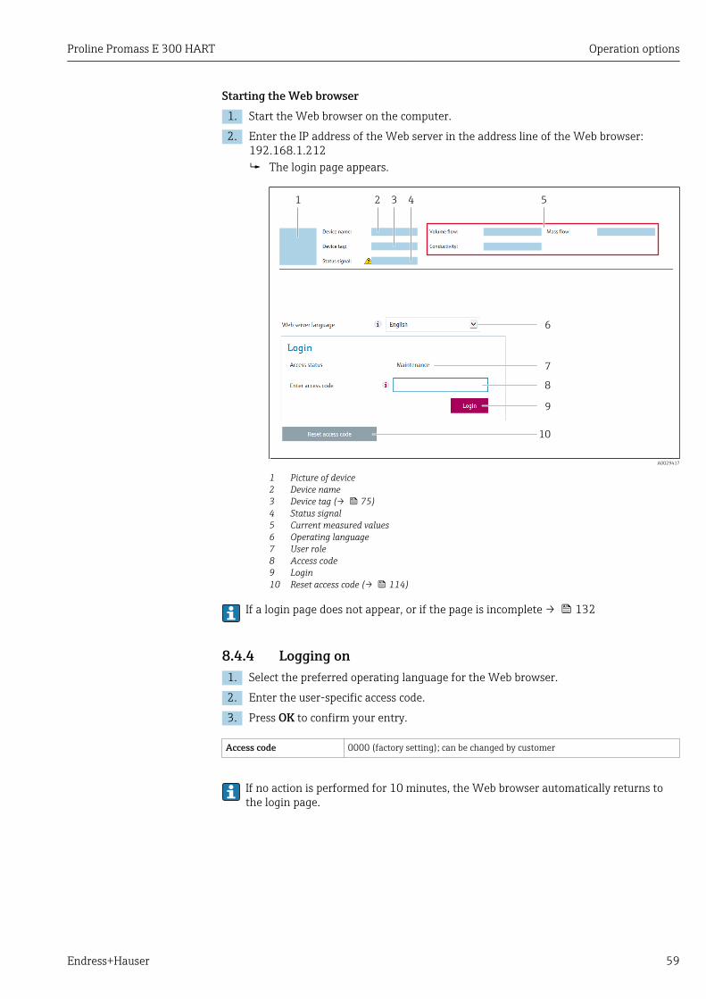
Proline Promass E 300 HART Operation options
Endress+Hauser 59
Starting the Web browser1. Start the Web browser on the computer.
2. Enter the IP address of the Web server in the address line of the Web browser:192.168.1.212 The login page appears.
6
7
8
9
10
1 52 3 4
A0029417
1 Picture of device2 Device name3 Device tag (→ 75)4 Status signal5 Current measured values6 Operating language7 User role8 Access code9 Login10 Reset access code (→ 114)
If a login page does not appear, or if the page is incomplete → 132
8.4.4 Logging on1. Select the preferred operating language for the Web browser.
2. Enter the user-specific access code.
3. Press OK to confirm your entry.
Access code 0000 (factory setting); can be changed by customer
If no action is performed for 10 minutes, the Web browser automatically returns tothe login page.
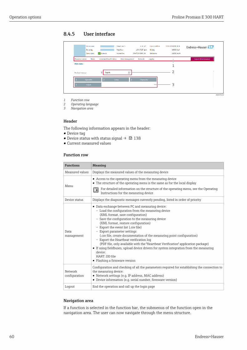
Operation options Proline Promass E 300 HART
60 Endress+Hauser
8.4.5 User interface
2
1
3
A0029418
1 Function row2 Operating language3 Navigation area
HeaderThe following information appears in the header:• Device tag• Device status with status signal → 138• Current measured values
Function row
Functions Meaning
Measured values Displays the measured values of the measuring device
Menu
• Access to the operating menu from the measuring device• The structure of the operating menu is the same as for the local display
For detailed information on the structure of the operating menu, see the OperatingInstructions for the measuring device
Device status Displays the diagnostic messages currently pending, listed in order of priority
Datamanagement
• Data exchange between PC and measuring device:– Load the configuration from the measuring device
(XML format, save configuration)– Save the configuration to the measuring device
(XML format, restore configuration)– Export the event list (.csv file)– Export parameter settings
(.csv file, create documentation of the measuring point configuration)– Export the Heartbeat verification log
(PDF file, only available with the "Heartbeat Verification" application package)• If using fieldbuses, upload device drivers for system integration from the measuring
device:HART: DD file
• Flashing a firmware version
Networkconfiguration
Configuration and checking of all the parameters required for establishing the connection tothe measuring device:• Network settings (e.g. IP address, MAC address)• Device information (e.g. serial number, firmware version)
Logout End the operation and call up the login page
Navigation areaIf a function is selected in the function bar, the submenus of the function open in thenavigation area. The user can now navigate through the menu structure.

Proline Promass E 300 HART Operation options
Endress+Hauser 61
Working areaDepending on the selected function and the related submenus, various actions can beperformed in this area:• Configuring parameters• Reading measured values• Calling up help text• Starting an upload/download
8.4.6 Disabling the Web serverThe Web server of the measuring device can be switched on and off as required using theWeb server functionality parameter.
Navigation"Expert" menu → Communication → Web server
Parameter overview with brief description
Parameter Description Selection Factory setting
Web server functionality Switch the Web server on and off. • Off• On
On
Function scope of the "Web server functionality" parameter
Option Description
Off • The web server is completely disabled.• Port 80 is locked.
On • The complete functionality of the web server is available.• JavaScript is used.• The password is transferred in an encrypted state.• Any change to the password is also transferred in an encrypted state.
Enabling the Web serverIf the Web server is disabled it can only be re-enabled with the Web server functionalityparameter via the following operating options:• Via local display• Via Bedientool "FieldCare"• Via "DeviceCare" operating tool
8.4.7 Logging outBefore logging out, perform a data backup via the Data management function(upload configuration from device) if necessary.
1. Select the Logout entry in the function row. The home page with the Login box appears.
2. Close the Web browser.
3. Reset the modified properties of the Internet protocol (TCP/IP) if they are no longerneeded → 58.
8.5 Access to the operating menu via the operating toolThe structure of the operating menu in the operating tools is the same as for operation viathe local display.

Operation options Proline Promass E 300 HART
62 Endress+Hauser
8.5.1 Connecting the operating tool
Via HART protocolThis communication interface is available in device versions with a HART output.
1 2 3 5
7
4 6
A0028747
24 Options for remote operation via HART protocol (active)
1 Control system (e.g. PLC)2 Field Communicator 4753 Computer with Web browser (e.g. Internet Explorer) for accessing the integrated device Web server or
computer with operating tool (e.g. FieldCare, DeviceCare, AMS Device Manager, SIMATIC PDM) with COMDTM "CDI Communication TCP/IP"
4 Commubox FXA195 (USB)5 Field Xpert SFX350 or SFX3706 VIATOR Bluetooth modem with connecting cable7 Transmitter
1 4 5 7
9
6 82 3
A0028746
25 Options for remote operation via HART protocol (passive)
1 Control system (e.g. PLC)2 Transmitter power supply unit, e.g. RN221N (with communication resistor)3 Connection for Commubox FXA195 and Field Communicator 4754 Field Communicator 4755 Computer with Web browser (e.g. Internet Explorer) for accessing the integrated device Web server or
computer with operating tool (e.g. FieldCare, DeviceCare, AMS Device Manager, SIMATIC PDM) with COMDTM "CDI Communication TCP/IP"
6 Commubox FXA195 (USB)7 Field Xpert SFX350 or SFX3708 VIATOR Bluetooth modem with connecting cable9 Transmitter

Proline Promass E 300 HART Operation options
Endress+Hauser 63
Service interfaceVia service interface (CDI-RJ45)
2
3
1
A0027563
26 Connection via service interface (CDI-RJ45)
1 Computer with Web browser (e.g. Microsoft Internet Explorer, Microsoft Edge) for accessing the integrateddevice Web server or with "FieldCare", "DeviceCare" operating tool with COM DTM "CDI Communication TCP/IP"
2 Standard Ethernet connecting cable with RJ45 connector3 Service interface (CDI-RJ45) of the measuring device with access to the integrated Web server
Via WLAN interface
The optional WLAN interface is available on the following device version:Order code for "Display; operation", option G "4-line, backlit, graphic display; touch control +WLAN"
21
5 6
3 4 3 4
A0028839
1 Transmitter with integrated WLAN antenna2 Transmitter with external WLAN antenna3 LED lit constantly: WLAN reception is enabled on measuring device4 LED flashing: WLAN connection established between operating unit and measuring device5 Computer with WLAN interface and Web browser (e.g. Microsoft Internet Explorer, Microsoft Edge) for
accessing the integrated device Web server or with operating tool (e.g. FieldCare, DeviceCare)6 Mobile handheld terminal with WLAN interface and Web browser (e.g. Microsoft Internet Explorer, Microsoft
Edge) for accessing the integrated device Web server or operating tool (e.g. FieldCare, DeviceCare)
Wireless LAN IEEE 802.11 b/g (2.4 GHz) WLAN
Encryption WPA2 PSK/TKIP AES-128
Configurable channels 1 to 11
Function Access point with DHCP
Operation options Proline Promass E 300 HART
64 Endress+Hauser
Range with integratedantenna
Max. 10 m (32 ft)
Range with externalantenna
Max. 50 m (164 ft)
Configuring the Internet protocol of the operating unit
NOTICEIf the WLAN connection is lost during the configuration, settings made may be lost.‣ Make sure that the WLAN connection is not disconnected while configuring the device.
NOTICEIn principle, avoid simultaneous access to the measuring device via the serviceinterface (CDI-RJ45) and the WLAN interface from the same operating unit. Thiscould cause a network conflict.‣ Only activate one service interface (CDI-RJ45 service interface or WLAN interface).‣ If simultaneous communication is necessary: configure different IP address ranges, e.g.
192.168.0.1 (WLAN interface) and 192.168.1.212 (CDI-RJ45 service interface).
Preparation
‣ Enable WLAN reception on the operating unit.
Establishing a connection
1. Select the measuring device using the SSID (e.g. EH_Promass_300_A802000).
2. If necessary, select the WPA2 encryption method.
3. Enter the password: serial number of the measuring device ex-works (e.g.L100A802000). LED on display module flashes: it is now possible to operate the measuring device
with the Web browser, FieldCare or DeviceCare.
The serial number can be found on the nameplate.
Disconnecting
‣ Once the configuration is completed, disconnect the WLAN connection between theoperating unit and the measuring device.
8.5.2 Field Xpert SFX350, SFX370
Function scopeField Xpert SFX350 and Field Xpert SFX370 are mobile computers for commissioning andmaintenance. They enable efficient device configuration and diagnostics for HART andFOUNDATION fieldbus devices in the non-Ex area (SFX350, SFX370) and the Ex area(SFX370).
For details, see Operating Instructions BA01202S
Source for device description filesSee data → 68

Proline Promass E 300 HART Operation options
Endress+Hauser 65
8.5.3 FieldCare
Function scopeFDT-based plant asset management tool from Endress+Hauser. It can configure all smartfield devices in a system and helps you manage them. By using the status information, it isalso a simple but effective way of checking their status and condition.
Access is via:• HART protocol• CDI-RJ45 service interface → 63• WLAN interface→ 63
Typical functions:• Configuring parameters of transmitters• Loading and saving device data (upload/download)• Documentation of the measuring point• Visualization of the measured value memory (line recorder) and event logbook
For additional information about FieldCare, see Operating Instructions BA00027Sand BA00059S
Source for device description filesSee information → 68
Establishing a connection1. Start FieldCare and launch the project.
2. In the network: Add a device. The Add device window opens.
3. Select the CDI Communication TCP/IP option from the list and press OK to confirm.
4. Right-click CDI Communication TCP/IP and select the Add device option in thecontext menu that opens.
5. Select the desired device from the list and press OK to confirm. The CDI Communication TCP/IP (Configuration) window opens.
6. Enter the device address in the IP address field: 192.168.1.212 and press Enter toconfirm.
7. Establish the online connection to the device.
For additional information, see Operating Instructions BA00027S and BA00059S
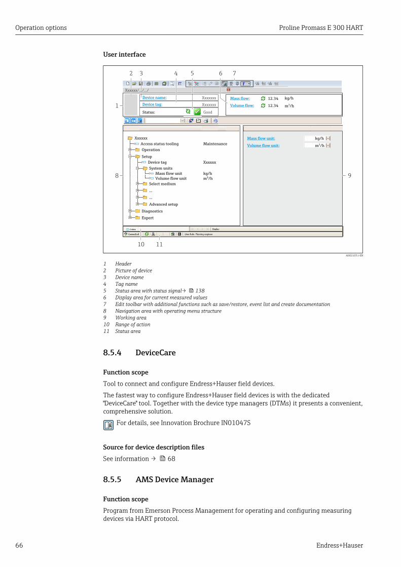
Operation options Proline Promass E 300 HART
66 Endress+Hauser
User interface
6532
1
Xxxxxx/…/…/
7
P
P
+
–
P
–
P
+
+
+
+
+
+
4
8 9
10 11
Xxxxxxx
GoodStatus:
Device tag:
XxxxxxxDevice name: Mass flow: 12.34 kg/h
Volume flow: 12.34 m /h³
Mass flow unit:
Volume flow unit:
kg/h
m /h³Access status tooling
Operation
Setup
Xxxxxx
Mass flow unitVolume flow unit
Select medium
Device tag
…
…
Advanced setup
Diagnostics
Expert
Maintenance
kg/hm /h³
Xxxxxx
System units
A0021051-EN
1 Header2 Picture of device3 Device name4 Tag name5 Status area with status signal→ 1386 Display area for current measured values7 Edit toolbar with additional functions such as save/restore, event list and create documentation8 Navigation area with operating menu structure9 Working area10 Range of action11 Status area
8.5.4 DeviceCare
Function scopeTool to connect and configure Endress+Hauser field devices.
The fastest way to configure Endress+Hauser field devices is with the dedicated"DeviceCare" tool. Together with the device type managers (DTMs) it presents a convenient,comprehensive solution.
For details, see Innovation Brochure IN01047S
Source for device description filesSee information → 68
8.5.5 AMS Device Manager
Function scopeProgram from Emerson Process Management for operating and configuring measuringdevices via HART protocol.

Proline Promass E 300 HART Operation options
Endress+Hauser 67
Source for device description filesSee data → 68
8.5.6 SIMATIC PDM
Function scopeSIMATIC PDM is a standardized, manufacturer-independent program from Siemens forthe operation, configuration, maintenance and diagnosis of intelligent field devices viaHART protocol.
Source for device description filesSee data → 68
8.5.7 Field Communicator 475
Function scopeIndustrial handheld terminal from Emerson Process Management for remoteconfiguration and measured value display via HART protocol.
Source for device description filesSee data → 68

System integration Proline Promass E 300 HART
68 Endress+Hauser
9 System integration
9.1 Overview of device description files
9.1.1 Current version data for the device
Firmware version 01.00.zz • On the title page of the Operating instructions• On the transmitter nameplate• Firmware version
Diagnostics → Device information → Firmwareversion
Release date of firmware version 08.2016 ---
Manufacturer ID 0x11 Manufacturer IDDiagnostics → Device information → Manufacturer ID
Device type ID 0x3B Device typeDiagnostics → Device information → Device type
HART protocol revision 7 ---
Device revision 1 • On the transmitter nameplate• Device revision
Diagnostics → Device information → Device revision
For an overview of the different firmware versions for the device → 151
9.1.2 Operating toolsThe suitable device description file for the individual operating tools is listed in the tablebelow, along with information on where the file can be acquired.
Operating tool viaHART protocol
Sources for obtaining device descriptions
FieldCare • www.endress.com → Download Area• CD–ROM (contact Endress+Hauser)• DVD (contact Endress+Hauser)
DeviceCare • www.endress.com → Download Area• CD–ROM (contact Endress+Hauser)• DVD (contact Endress+Hauser)
• Field Xpert SFX350• Field Xpert SFX370
Use update function of handheld terminal
AMS Device Manager(Emerson Process Management)
www.endress.com → Download Area
SIMATIC PDM(Siemens)
www.endress.com → Download Area
Field Communicator 475(Emerson Process Management)
Use update function of handheld terminal
9.2 Measured variables via HART protocolThe following measured variables (HART device variables) are assigned to the dynamicvariables at the factory:
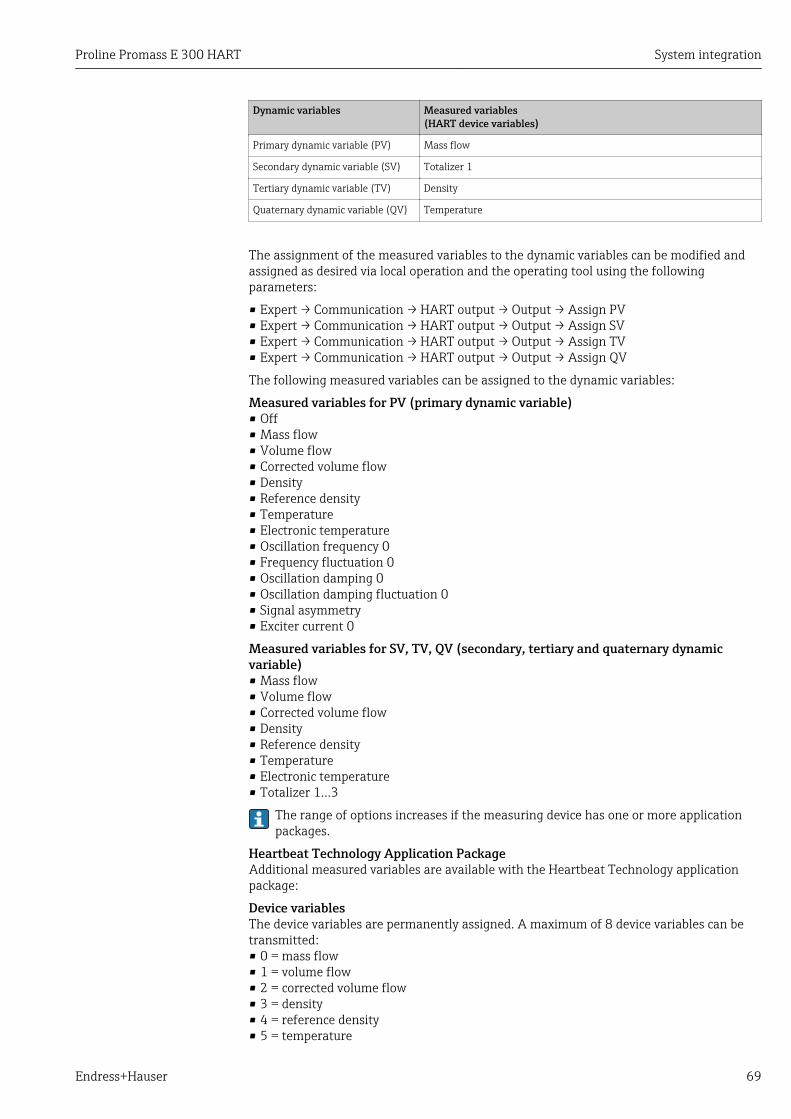
Proline Promass E 300 HART System integration
Endress+Hauser 69
Dynamic variables Measured variables(HART device variables)
Primary dynamic variable (PV) Mass flow
Secondary dynamic variable (SV) Totalizer 1
Tertiary dynamic variable (TV) Density
Quaternary dynamic variable (QV) Temperature
The assignment of the measured variables to the dynamic variables can be modified andassigned as desired via local operation and the operating tool using the followingparameters:
• Expert → Communication → HART output → Output → Assign PV• Expert → Communication → HART output → Output → Assign SV• Expert → Communication → HART output → Output → Assign TV• Expert → Communication → HART output → Output → Assign QV
The following measured variables can be assigned to the dynamic variables:
Measured variables for PV (primary dynamic variable)• Off• Mass flow• Volume flow• Corrected volume flow• Density• Reference density• Temperature• Electronic temperature• Oscillation frequency 0• Frequency fluctuation 0• Oscillation damping 0• Oscillation damping fluctuation 0• Signal asymmetry• Exciter current 0
Measured variables for SV, TV, QV (secondary, tertiary and quaternary dynamicvariable)• Mass flow• Volume flow• Corrected volume flow• Density• Reference density• Temperature• Electronic temperature• Totalizer 1…3
The range of options increases if the measuring device has one or more applicationpackages.
Heartbeat Technology Application PackageAdditional measured variables are available with the Heartbeat Technology applicationpackage:
Device variablesThe device variables are permanently assigned. A maximum of 8 device variables can betransmitted:• 0 = mass flow• 1 = volume flow• 2 = corrected volume flow• 3 = density• 4 = reference density• 5 = temperature
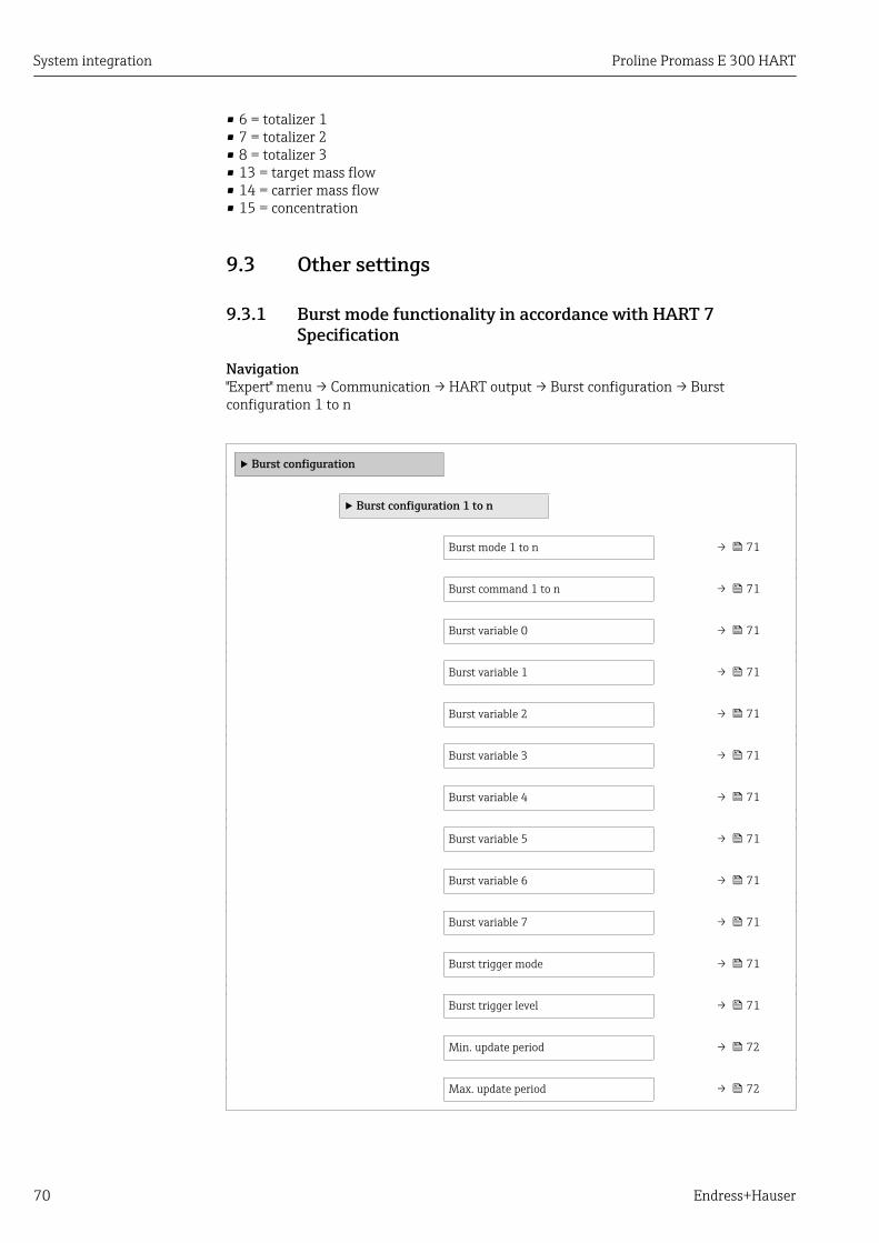
System integration Proline Promass E 300 HART
70 Endress+Hauser
• 6 = totalizer 1• 7 = totalizer 2• 8 = totalizer 3• 13 = target mass flow• 14 = carrier mass flow• 15 = concentration
9.3 Other settings
9.3.1 Burst mode functionality in accordance with HART 7Specification
Navigation"Expert" menu → Communication → HART output → Burst configuration → Burstconfiguration 1 to n
‣ Burst configuration
‣ Burst configuration 1 to n
Burst mode 1 to n → 71
Burst command 1 to n → 71
Burst variable 0 → 71
Burst variable 1 → 71
Burst variable 2 → 71
Burst variable 3 → 71
Burst variable 4 → 71
Burst variable 5 → 71
Burst variable 6 → 71
Burst variable 7 → 71
Burst trigger mode → 71
Burst trigger level → 71
Min. update period → 72
Max. update period → 72
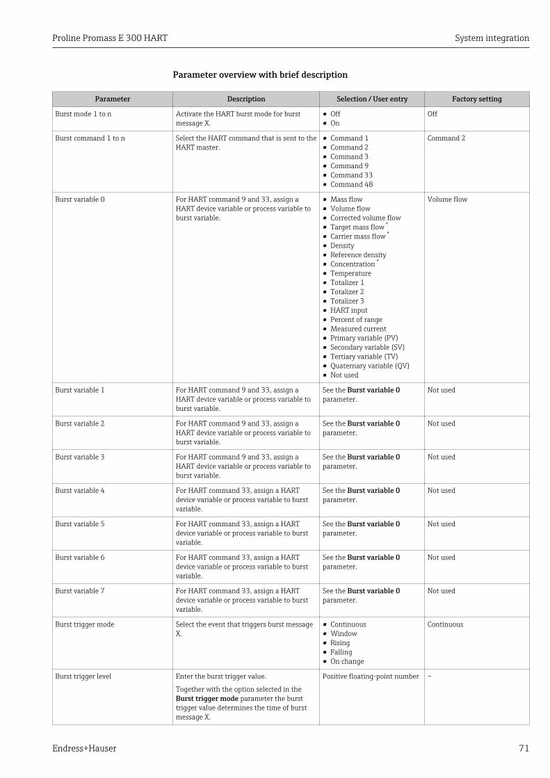
Proline Promass E 300 HART System integration
Endress+Hauser 71
Parameter overview with brief description
Parameter Description Selection / User entry Factory setting
Burst mode 1 to n Activate the HART burst mode for burstmessage X.
• Off• On
Off
Burst command 1 to n Select the HART command that is sent to theHART master.
• Command 1• Command 2• Command 3• Command 9• Command 33• Command 48
Command 2
Burst variable 0 For HART command 9 and 33, assign aHART device variable or process variable toburst variable.
• Mass flow• Volume flow• Corrected volume flow• Target mass flow *
• Carrier mass flow *
• Density• Reference density• Concentration *
• Temperature• Totalizer 1• Totalizer 2• Totalizer 3• HART input• Percent of range• Measured current• Primary variable (PV)• Secondary variable (SV)• Tertiary variable (TV)• Quaternary variable (QV)• Not used
Volume flow
Burst variable 1 For HART command 9 and 33, assign aHART device variable or process variable toburst variable.
See the Burst variable 0parameter.
Not used
Burst variable 2 For HART command 9 and 33, assign aHART device variable or process variable toburst variable.
See the Burst variable 0parameter.
Not used
Burst variable 3 For HART command 9 and 33, assign aHART device variable or process variable toburst variable.
See the Burst variable 0parameter.
Not used
Burst variable 4 For HART command 33, assign a HARTdevice variable or process variable to burstvariable.
See the Burst variable 0parameter.
Not used
Burst variable 5 For HART command 33, assign a HARTdevice variable or process variable to burstvariable.
See the Burst variable 0parameter.
Not used
Burst variable 6 For HART command 33, assign a HARTdevice variable or process variable to burstvariable.
See the Burst variable 0parameter.
Not used
Burst variable 7 For HART command 33, assign a HARTdevice variable or process variable to burstvariable.
See the Burst variable 0parameter.
Not used
Burst trigger mode Select the event that triggers burst messageX.
• Continuous• Window• Rising• Falling• On change
Continuous
Burst trigger level Enter the burst trigger value.
Together with the option selected in theBurst trigger mode parameter the bursttrigger value determines the time of burstmessage X.
Positive floating-point number –

System integration Proline Promass E 300 HART
72 Endress+Hauser
Parameter Description Selection / User entry Factory setting
Min. update period Enter the minimum time span between twoburst responses of one burst message.
Positive integer 1 000 ms
Max. update period Enter the maximum time span between twoburst responses of one burst message.
Positive integer 2 000 ms
* Visibility depends on order options or device settings
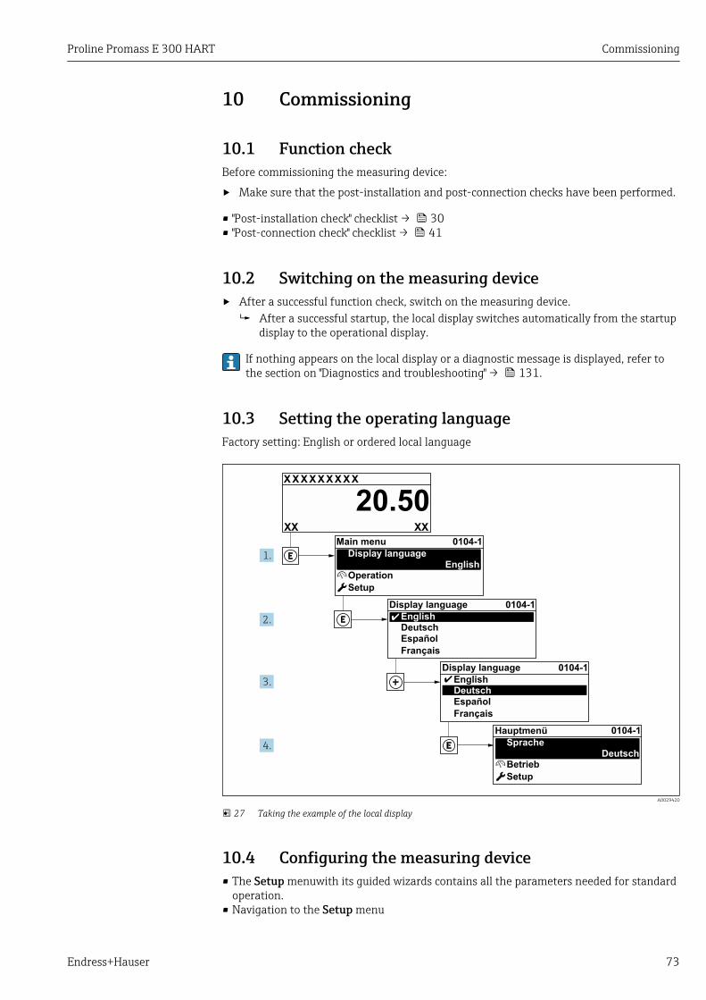
Proline Promass E 300 HART Commissioning
Endress+Hauser 73
10 Commissioning
10.1 Function checkBefore commissioning the measuring device:
‣ Make sure that the post-installation and post-connection checks have been performed.
• "Post-installation check" checklist → 30• "Post-connection check" checklist → 41
10.2 Switching on the measuring device‣ After a successful function check, switch on the measuring device.
After a successful startup, the local display switches automatically from the startupdisplay to the operational display.
If nothing appears on the local display or a diagnostic message is displayed, refer tothe section on "Diagnostics and troubleshooting" → 131.
10.3 Setting the operating languageFactory setting: English or ordered local language
X X X X X X XX X
20.50
Operation
Setup
Main menu 0104-1
Display languageEnglish
Español
Français
Display language
EnglishDeutsch
Ã
0104-1
Ã
Español
Français
Display language
EnglishDeutsch
0104-1
Betrieb
Setup
Hauptmenü
SpracheDeutsch
0104-1
XXXX
1.
2.
3.
4.
A0029420
27 Taking the example of the local display
10.4 Configuring the measuring device• The Setup menuwith its guided wizards contains all the parameters needed for standard
operation.• Navigation to the Setup menu
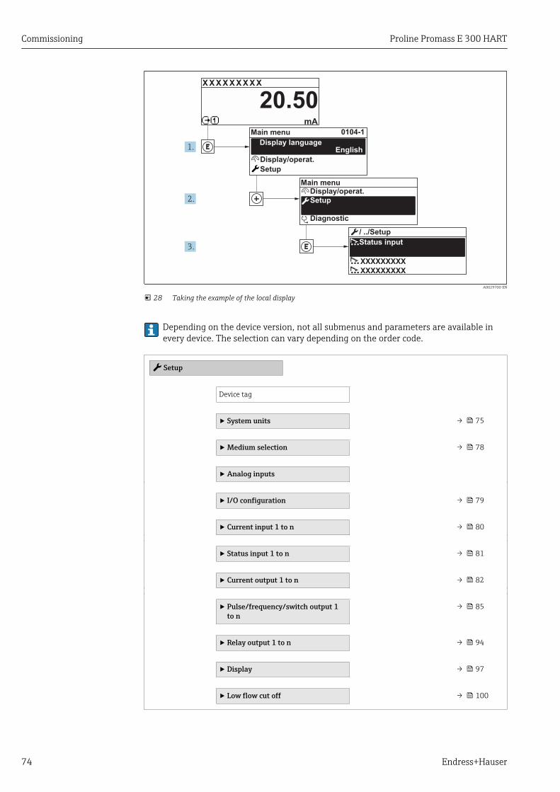
Commissioning Proline Promass E 300 HART
74 Endress+Hauser
X X X X X X XX X
20.500104-1
XXXXXXXXX
XXXXXXXXX
mA
1.
2.
3.
Display/operat.
Setup
Diagnostic
Display/operat.
Setup
Main menu
English
Main menu
Status input
/ ../Setup
Display language
A0029700-EN
28 Taking the example of the local display
Depending on the device version, not all submenus and parameters are available inevery device. The selection can vary depending on the order code.
Setup
Device tag
‣ System units → 75
‣ Medium selection → 78
‣ Analog inputs
‣ I/O configuration → 79
‣ Current input 1 to n → 80
‣ Status input 1 to n → 81
‣ Current output 1 to n → 82
‣ Pulse/frequency/switch output 1to n
→ 85
‣ Relay output 1 to n → 94
‣ Display → 97
‣ Low flow cut off → 100
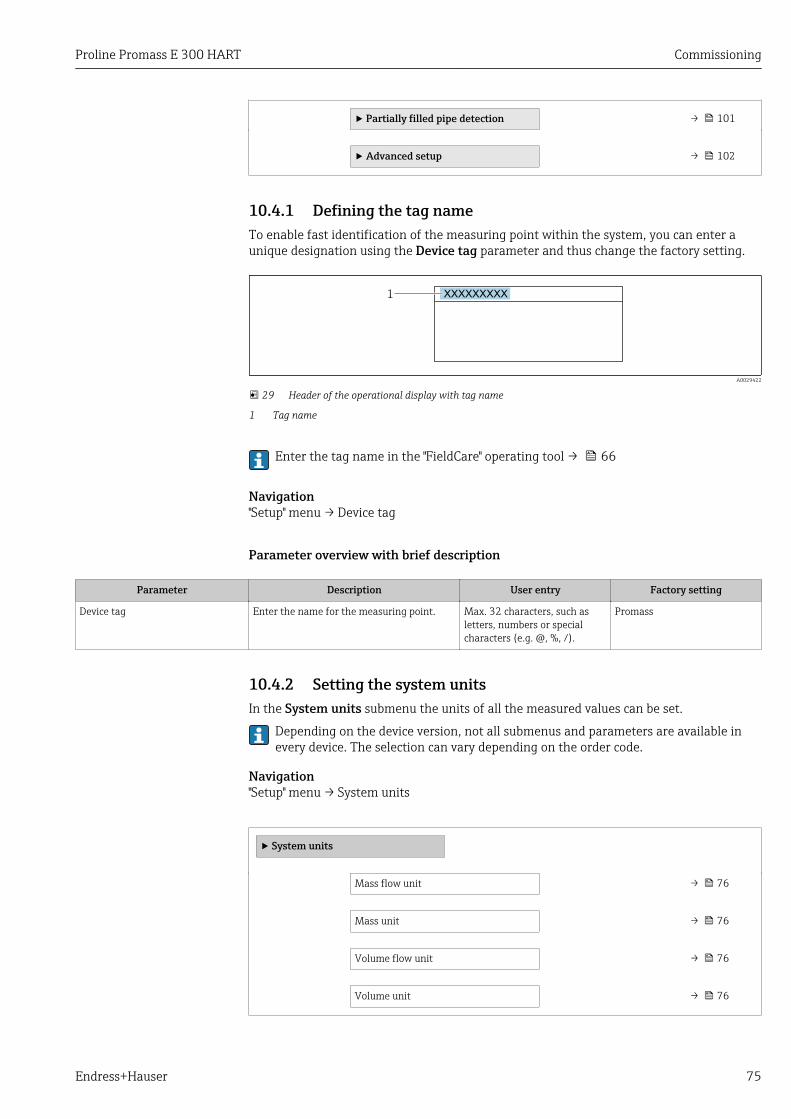
Proline Promass E 300 HART Commissioning
Endress+Hauser 75
‣ Partially filled pipe detection → 101
‣ Advanced setup → 102
10.4.1 Defining the tag nameTo enable fast identification of the measuring point within the system, you can enter aunique designation using the Device tag parameter and thus change the factory setting.
1 XXXXXXXXX
A0029422
29 Header of the operational display with tag name
1 Tag name
Enter the tag name in the "FieldCare" operating tool → 66
Navigation"Setup" menu → Device tag
Parameter overview with brief description
Parameter Description User entry Factory setting
Device tag Enter the name for the measuring point. Max. 32 characters, such asletters, numbers or specialcharacters (e.g. @, %, /).
Promass
10.4.2 Setting the system unitsIn the System units submenu the units of all the measured values can be set.
Depending on the device version, not all submenus and parameters are available inevery device. The selection can vary depending on the order code.
Navigation"Setup" menu → System units
‣ System units
Mass flow unit → 76
Mass unit → 76
Volume flow unit → 76
Volume unit → 76

Commissioning Proline Promass E 300 HART
76 Endress+Hauser
Corrected volume flow unit → 76
Corrected volume unit → 76
Density unit → 76
Reference density unit → 76
Temperature unit → 77
Pressure unit → 77
Parameter overview with brief description
Parameter Description Selection Factory setting
Mass flow unit Select mass flow unit.
Result
The selected unit applies for:• Output• Low flow cut off• Simulation process variable
Unit choose list Country-specific:• kg/h• lb/min
Mass unit Select mass unit. Unit choose list Country-specific:• kg• lb
Volume flow unit Select volume flow unit.
Result
The selected unit applies for:• Output• Low flow cut off• Simulation process variable
Unit choose list Country-specific:• l/h• gal/min (us)
Volume unit Select volume unit. Unit choose list Country-specific:• l (DN > 150 (6"): m³)• gal (us)
Corrected volume flow unit Select corrected volume flow unit.
Result
The selected unit applies for:Corrected volume flow parameter(→ 121)
Unit choose list Country-specific:• Nl/h• Sft³/min
Corrected volume unit Select corrected volume unit. Unit choose list Country-specific:• Nl• Sft³
Density unit Select density unit.
Result
The selected unit applies for:• Output• Simulation process variable• Density adjustment (Expert menu)
Unit choose list Country-specific:• kg/l• lb/ft³
Reference density unit Select reference density unit. Unit choose list Country-dependent• kg/Nl• lb/Sft³

Proline Promass E 300 HART Commissioning
Endress+Hauser 77
Parameter Description Selection Factory setting
Temperature unit Select temperature unit.
Result
The selected unit applies for:• Electronic temperature parameter
(6053)• Maximum value parameter (6051)• Minimum value parameter (6052)• External temperature parameter (6080)• Maximum value parameter (6108)• Minimum value parameter (6109)• Carrier pipe temperature parameter
(6027)• Maximum value parameter (6029)• Minimum value parameter (6030)• Reference temperature parameter
(1816)• Temperature parameter
Unit choose list Country-specific:• °C• °F
Pressure unit Select process pressure unit.
Result
The unit is taken from:• Pressure value parameter (→ 79)• External pressure parameter
(→ 79)• Pressure value
Unit choose list Country-specific:• bar a• psi a
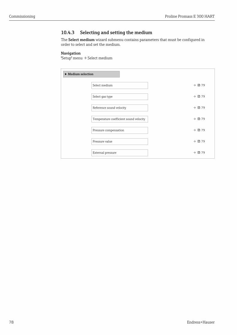
Commissioning Proline Promass E 300 HART
78 Endress+Hauser
10.4.3 Selecting and setting the mediumThe Select medium wizard submenu contains parameters that must be configured inorder to select and set the medium.
Navigation"Setup" menu → Select medium
‣ Medium selection
Select medium → 79
Select gas type → 79
Reference sound velocity → 79
Temperature coefficient sound velocity → 79
Pressure compensation → 79
Pressure value → 79
External pressure → 79
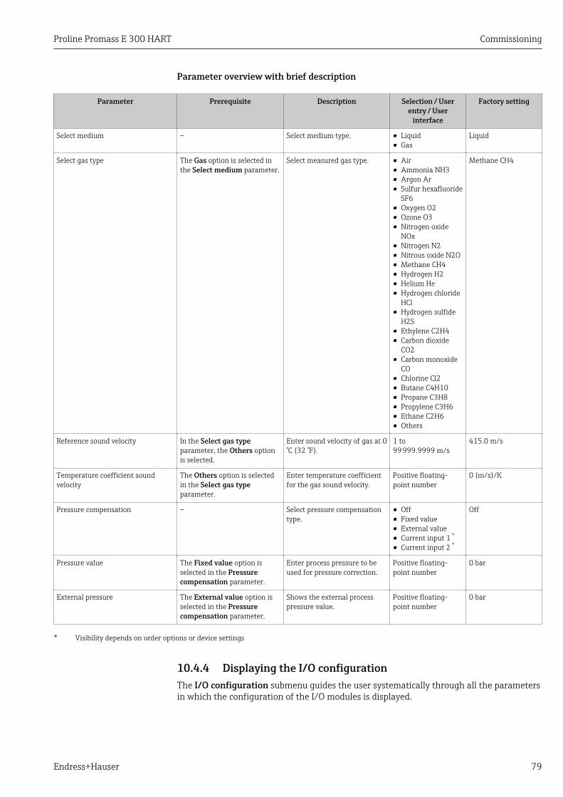
Proline Promass E 300 HART Commissioning
Endress+Hauser 79
Parameter overview with brief description
Parameter Prerequisite Description Selection / Userentry / User
interface
Factory setting
Select medium – Select medium type. • Liquid• Gas
Liquid
Select gas type The Gas option is selected inthe Select medium parameter.
Select measured gas type. • Air• Ammonia NH3• Argon Ar• Sulfur hexafluoride
SF6• Oxygen O2• Ozone O3• Nitrogen oxide
NOx• Nitrogen N2• Nitrous oxide N2O• Methane CH4• Hydrogen H2• Helium He• Hydrogen chloride
HCl• Hydrogen sulfide
H2S• Ethylene C2H4• Carbon dioxide
CO2• Carbon monoxide
CO• Chlorine Cl2• Butane C4H10• Propane C3H8• Propylene C3H6• Ethane C2H6• Others
Methane CH4
Reference sound velocity In the Select gas typeparameter, the Others optionis selected.
Enter sound velocity of gas at 0°C (32 °F).
1 to99 999.9999 m/s
415.0 m/s
Temperature coefficient soundvelocity
The Others option is selectedin the Select gas typeparameter.
Enter temperature coefficientfor the gas sound velocity.
Positive floating-point number
0 (m/s)/K
Pressure compensation – Select pressure compensationtype.
• Off• Fixed value• External value• Current input 1 *
• Current input 2 *
Off
Pressure value The Fixed value option isselected in the Pressurecompensation parameter.
Enter process pressure to beused for pressure correction.
Positive floating-point number
0 bar
External pressure The External value option isselected in the Pressurecompensation parameter.
Shows the external processpressure value.
Positive floating-point number
0 bar
* Visibility depends on order options or device settings
10.4.4 Displaying the I/O configurationThe I/O configuration submenu guides the user systematically through all the parametersin which the configuration of the I/O modules is displayed.

Commissioning Proline Promass E 300 HART
80 Endress+Hauser
Navigation"Setup" menu → I/O configuration
‣ I/O configuration
I/O module 1 to n terminal numbers → 80
I/O module 1 to n information → 80
I/O module 1 to n type → 80
Apply I/O configuration → 80
Conversion code → 80
Parameter overview with brief description
Parameter Description User interface / Selection / User entry
Factory setting
I/O module 1 to n terminal numbers Shows the terminal numbers used by the I/Omodule.
• Not used• 26-27 (I/O 1)• 24-25 (I/O 2)• 22-23 (I/O 3)
–
I/O module 1 to n information Shows information of the plugged I/Omodule.
• Not plugged• Invalid• Not configurable• Configurable• Fieldbus
–
I/O module 1 to n type Shows the I/O module type. • Off• Current output *
• Current input *
• Status input *
• Pulse/frequency/switchoutput *
Off
Apply I/O configuration Apply parameterization of the freelyconfigurable I/O module.
• No• Yes
No
Conversion code Enter the code in order to change the I/Oconfiguration.
Positive integer 0
* Visibility depends on order options or device settings
10.4.5 Configuring the current inputThe "Current input" wizard guides the user systematically through all the parameters thathave to be set for configuring the current input.
Navigation"Setup" menu → Current input
‣ Current input 1 to n
Terminal number → 81
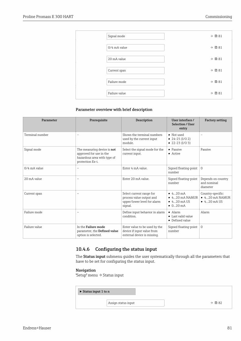
Proline Promass E 300 HART Commissioning
Endress+Hauser 81
Signal mode → 81
0/4 mA value → 81
20 mA value → 81
Current span → 81
Failure mode → 81
Failure value → 81
Parameter overview with brief description
Parameter Prerequisite Description User interface / Selection / User
entry
Factory setting
Terminal number – Shows the terminal numbersused by the current inputmodule.
• Not used• 24-25 (I/O 2)• 22-23 (I/O 3)
–
Signal mode The measuring device is notapproved for use in thehazardous area with type ofprotection Ex-i.
Select the signal mode for thecurrent input.
• Passive• Active
Passive
0/4 mA value – Enter 4 mA value. Signed floating-pointnumber
0
20 mA value – Enter 20 mA value. Signed floating-pointnumber
Depends on countryand nominaldiameter
Current span – Select current range forprocess value output andupper/lower level for alarmsignal.
• 4...20 mA• 4...20 mA NAMUR• 4...20 mA US• 0...20 mA
Country-specific:• 4...20 mA NAMUR• 4...20 mA US
Failure mode – Define input behavior in alarmcondition.
• Alarm• Last valid value• Defined value
Alarm
Failure value In the Failure modeparameter, the Defined valueoption is selected.
Enter value to be used by thedevice if input value fromexternal device is missing.
Signed floating-pointnumber
0
10.4.6 Configuring the status inputThe Status input submenu guides the user systematically through all the parameters thathave to be set for configuring the status input.
Navigation"Setup" menu → Status input
‣ Status input 1 to n
Assign status input → 82
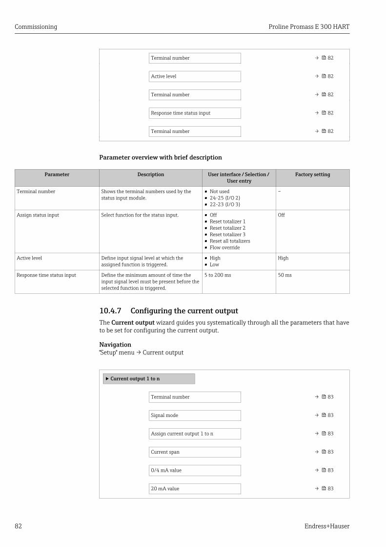
Commissioning Proline Promass E 300 HART
82 Endress+Hauser
Terminal number → 82
Active level → 82
Terminal number → 82
Response time status input → 82
Terminal number → 82
Parameter overview with brief description
Parameter Description User interface / Selection / User entry
Factory setting
Terminal number Shows the terminal numbers used by thestatus input module.
• Not used• 24-25 (I/O 2)• 22-23 (I/O 3)
–
Assign status input Select function for the status input. • Off• Reset totalizer 1• Reset totalizer 2• Reset totalizer 3• Reset all totalizers• Flow override
Off
Active level Define input signal level at which theassigned function is triggered.
• High• Low
High
Response time status input Define the minimum amount of time theinput signal level must be present before theselected function is triggered.
5 to 200 ms 50 ms
10.4.7 Configuring the current outputThe Current output wizard guides you systematically through all the parameters that haveto be set for configuring the current output.
Navigation"Setup" menu → Current output
‣ Current output 1 to n
Terminal number → 83
Signal mode → 83
Assign current output 1 to n → 83
Current span → 83
0/4 mA value → 83
20 mA value → 83
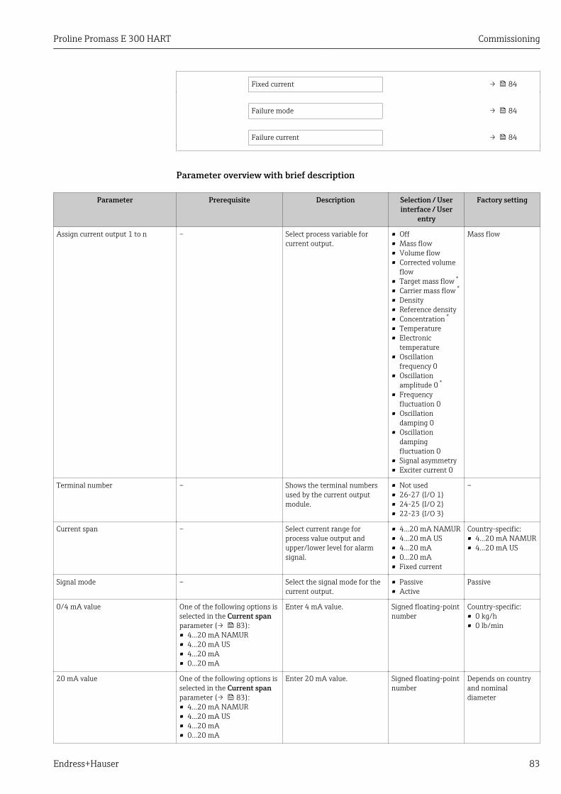
Proline Promass E 300 HART Commissioning
Endress+Hauser 83
Fixed current → 84
Failure mode → 84
Failure current → 84
Parameter overview with brief description
Parameter Prerequisite Description Selection / Userinterface / User
entry
Factory setting
Assign current output 1 to n – Select process variable forcurrent output.
• Off• Mass flow• Volume flow• Corrected volume
flow• Target mass flow *
• Carrier mass flow *
• Density• Reference density• Concentration *
• Temperature• Electronic
temperature• Oscillation
frequency 0• Oscillation
amplitude 0 *
• Frequencyfluctuation 0
• Oscillationdamping 0
• Oscillationdampingfluctuation 0
• Signal asymmetry• Exciter current 0
Mass flow
Terminal number – Shows the terminal numbersused by the current outputmodule.
• Not used• 26-27 (I/O 1)• 24-25 (I/O 2)• 22-23 (I/O 3)
–
Current span – Select current range forprocess value output andupper/lower level for alarmsignal.
• 4...20 mA NAMUR• 4...20 mA US• 4...20 mA• 0...20 mA• Fixed current
Country-specific:• 4...20 mA NAMUR• 4...20 mA US
Signal mode – Select the signal mode for thecurrent output.
• Passive• Active
Passive
0/4 mA value One of the following options isselected in the Current spanparameter (→ 83):• 4...20 mA NAMUR• 4...20 mA US• 4...20 mA• 0...20 mA
Enter 4 mA value. Signed floating-pointnumber
Country-specific:• 0 kg/h• 0 lb/min
20 mA value One of the following options isselected in the Current spanparameter (→ 83):• 4...20 mA NAMUR• 4...20 mA US• 4...20 mA• 0...20 mA
Enter 20 mA value. Signed floating-pointnumber
Depends on countryand nominaldiameter
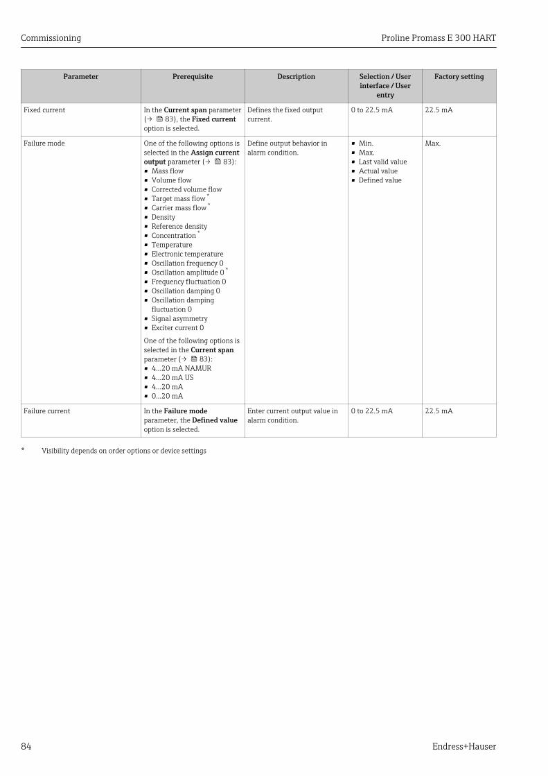
Commissioning Proline Promass E 300 HART
84 Endress+Hauser
Parameter Prerequisite Description Selection / Userinterface / User
entry
Factory setting
Fixed current In the Current span parameter(→ 83), the Fixed currentoption is selected.
Defines the fixed outputcurrent.
0 to 22.5 mA 22.5 mA
Failure mode One of the following options isselected in the Assign currentoutput parameter (→ 83):• Mass flow• Volume flow• Corrected volume flow• Target mass flow *
• Carrier mass flow *
• Density• Reference density• Concentration *
• Temperature• Electronic temperature• Oscillation frequency 0• Oscillation amplitude 0 *
• Frequency fluctuation 0• Oscillation damping 0• Oscillation damping
fluctuation 0• Signal asymmetry• Exciter current 0
One of the following options isselected in the Current spanparameter (→ 83):• 4...20 mA NAMUR• 4...20 mA US• 4...20 mA• 0...20 mA
Define output behavior inalarm condition.
• Min.• Max.• Last valid value• Actual value• Defined value
Max.
Failure current In the Failure modeparameter, the Defined valueoption is selected.
Enter current output value inalarm condition.
0 to 22.5 mA 22.5 mA
* Visibility depends on order options or device settings
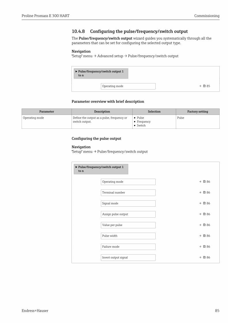
Proline Promass E 300 HART Commissioning
Endress+Hauser 85
10.4.8 Configuring the pulse/frequency/switch outputThe Pulse/frequency/switch output wizard guides you systematically through all theparameters that can be set for configuring the selected output type.
Navigation"Setup" menu → Advanced setup → Pulse/frequency/switch output
‣ Pulse/frequency/switch output 1to n
Operating mode → 85
Parameter overview with brief description
Parameter Description Selection Factory setting
Operating mode Define the output as a pulse, frequency orswitch output.
• Pulse• Frequency• Switch
Pulse
Configuring the pulse output
Navigation"Setup" menu → Pulse/frequency/switch output
‣ Pulse/frequency/switch output 1to n
Operating mode → 86
Terminal number → 86
Signal mode → 86
Assign pulse output → 86
Value per pulse → 86
Pulse width → 86
Failure mode → 86
Invert output signal → 86

Commissioning Proline Promass E 300 HART
86 Endress+Hauser
Parameter overview with brief description
Parameter Prerequisite Description Selection / Userinterface / User
entry
Factory setting
Operating mode – Define the output as a pulse,frequency or switch output.
• Pulse• Frequency• Switch
Pulse
Terminal number – Shows the terminal numbersused by the PFS outputmodule.
• Not used• 24-25 (I/O 2)• 22-23 (I/O 3)
–
Signal mode – Select the signal mode for thePFS output.
• Passive• Active
Passive
Assign pulse output 1 to n In the Operating modeparameter, the Pulse option isselected.
Select process variable forpulse output.
• Off• Mass flow• Volume flow• Corrected volume
flow• Target mass flow *
• Carrier mass flow *
Off
Value per pulse In the Operating modeparameter, the Pulse option isselected and one of thefollowing options is selected inthe Assign pulse outputparameter (→ 86):• Mass flow• Volume flow• Corrected volume flow• Target mass flow *
• Carrier mass flow *
Enter measured value at whicha pulse is output.
Signed floating-pointnumber
Depends on countryand nominaldiameter
Pulse width In the Operating modeparameter, the Pulse option isselected and one of thefollowing options is selected inthe Assign pulse outputparameter (→ 86):• Mass flow• Volume flow• Corrected volume flow• Target mass flow *
• Carrier mass flow *
Define time width of theoutput pulse.
0.05 to 2 000 ms 100 ms
Failure mode In the Operating modeparameter, the Pulse option isselected and one of thefollowing options is selected inthe Assign pulse outputparameter (→ 86):• Mass flow• Volume flow• Corrected volume flow• Target mass flow *
• Carrier mass flow *
Define output behavior inalarm condition.
• Actual value• No pulses
No pulses
Invert output signal – Invert the output signal. • No• Yes
No
* Visibility depends on order options or device settings

Proline Promass E 300 HART Commissioning
Endress+Hauser 87
Configuring the frequency output
Navigation"Setup" menu → Pulse/frequency/switch output
‣ Pulse/frequency/switch output 1to n
Operating mode → 87
Terminal number → 87
Signal mode → 87
Assign frequency output → 88
Minimum frequency value → 88
Maximum frequency value → 89
Measuring value at minimumfrequency
→ 89
Measuring value at maximumfrequency
→ 90
Failure mode → 90
Failure frequency → 91
Invert output signal → 91
Parameter overview with brief description
Parameter Prerequisite Description Selection / Userinterface / User
entry
Factory setting
Operating mode – Define the output as a pulse,frequency or switch output.
• Pulse• Frequency• Switch
Pulse
Terminal number – Shows the terminal numbersused by the PFS outputmodule.
• Not used• 24-25 (I/O 2)• 22-23 (I/O 3)
–
Signal mode – Select the signal mode for thePFS output.
• Passive• Active
Passive

Commissioning Proline Promass E 300 HART
88 Endress+Hauser
Parameter Prerequisite Description Selection / Userinterface / User
entry
Factory setting
Assign frequency output In the Operating modeparameter (→ 85), theFrequency option is selected.
Select process variable forfrequency output.
• Off• Mass flow• Volume flow• Corrected volume
flow• Target mass flow *
• Carrier mass flow *
• Density• Reference density• Concentration *
• Temperature• Electronic
temperature• Oscillation
frequency 0• Oscillation
amplitude 0 *
• Frequencyfluctuation 0
• Oscillationdamping 0
• Oscillationdampingfluctuation 0
• Signal asymmetry• Exciter current 0• HBSI
Off
Minimum frequency value In the Operating modeparameter, the Frequencyoption is selected and one ofthe following options isselected in the Assignfrequency output parameter(→ 88):• Mass flow• Volume flow• Corrected volume flow• Target mass flow *
• Carrier mass flow *
• Density• Reference density• Concentration *
• Temperature• Electronic temperature• Oscillation frequency 0• Frequency fluctuation 0• Oscillation amplitude 0 *
• Oscillation damping 0• Oscillation damping
fluctuation 0• Signal asymmetry• Exciter current 0
Enter minimum frequency. 0.0 to 10 000.0 Hz 0.0 Hz

Proline Promass E 300 HART Commissioning
Endress+Hauser 89
Parameter Prerequisite Description Selection / Userinterface / User
entry
Factory setting
Maximum frequency value In the Operating modeparameter, the Frequencyoption is selected and one ofthe following options isselected in the Assignfrequency output parameter(→ 88):• Mass flow• Volume flow• Corrected volume flow• Target mass flow *
• Carrier mass flow *
• Density• Reference density• Concentration *
• Temperature• Electronic temperature• Oscillation frequency 0• Frequency fluctuation 0• Oscillation amplitude 0 *
• Oscillation damping 0• Oscillation damping
fluctuation 0• Signal asymmetry• Exciter current 0
Enter maximum frequency. 0.0 to 10 000.0 Hz 10 000.0 Hz
Measuring value at minimumfrequency
In the Operating modeparameter, the Frequencyoption is selected and one ofthe following options isselected in the Assignfrequency output parameter(→ 88):• Mass flow• Volume flow• Corrected volume flow• Target mass flow *
• Carrier mass flow *
• Density• Reference density• Concentration *
• Temperature• Electronic temperature• Oscillation frequency 0• Frequency fluctuation 0• Oscillation amplitude 0 *
• Oscillation damping 0• Oscillation damping
fluctuation 0• Signal asymmetry• Exciter current 0
Enter measured value forminmum frequency.
Signed floating-pointnumber
Depends on countryand nominaldiameter

Commissioning Proline Promass E 300 HART
90 Endress+Hauser
Parameter Prerequisite Description Selection / Userinterface / User
entry
Factory setting
Measuring value at maximumfrequency
In the Operating modeparameter, the Frequencyoption is selected and one ofthe following options isselected in the Assignfrequency output parameter(→ 88):• Mass flow• Volume flow• Corrected volume flow• Target mass flow *
• Carrier mass flow *
• Density• Reference density• Concentration *
• Temperature• Electronic temperature• Oscillation frequency 0• Frequency fluctuation 0• Oscillation amplitude 0 *
• Oscillation damping 0• Oscillation damping
fluctuation 0• Signal asymmetry• Exciter current 0
Enter measured value formaximum frequency.
Signed floating-pointnumber
Depends on countryand nominaldiameter
Failure mode In the Operating modeparameter, the Frequencyoption is selected and one ofthe following options isselected in the Assignfrequency output parameter(→ 88):• Mass flow• Volume flow• Corrected volume flow• Target mass flow *
• Carrier mass flow *
• Density• Reference density• Concentration *
• Temperature• Electronic temperature• Oscillation frequency 0• Frequency fluctuation 0• Oscillation amplitude 0 *
• Oscillation damping 0• Oscillation damping
fluctuation 0• Signal asymmetry• Exciter current 0
Define output behavior inalarm condition.
• Actual value• Defined value• 0 Hz
0 Hz

Proline Promass E 300 HART Commissioning
Endress+Hauser 91
Parameter Prerequisite Description Selection / Userinterface / User
entry
Factory setting
Failure frequency In the Operating modeparameter, the Frequencyoption is selected and one ofthe following options isselected in the Assignfrequency output parameter(→ 88):• Mass flow• Volume flow• Corrected volume flow• Target mass flow *
• Carrier mass flow *
• Density• Reference density• Concentration *
• Temperature• Electronic temperature• Oscillation frequency 0• Frequency fluctuation 0• Oscillation amplitude 0 *
• Oscillation damping 0• Oscillation damping
fluctuation 0• Signal asymmetry• Exciter current 0
Enter frequency output valuein alarm condition.
0.0 to 12 500.0 Hz 0.0 Hz
Invert output signal – Invert the output signal. • No• Yes
No
* Visibility depends on order options or device settings

Commissioning Proline Promass E 300 HART
92 Endress+Hauser
Configuring the switch output
Navigation"Setup" menu → Pulse/frequency/switch output
‣ Pulse/frequency/switch output 1to n
Operating mode → 92
Terminal number → 92
Signal mode → 92
Switch output function → 93
Assign diagnostic behavior → 93
Assign limit → 93
Assign flow direction check → 93
Assign status → 93
Switch-on value → 93
Switch-off value → 93
Switch-on delay → 93
Switch-off delay → 94
Failure mode → 94
Invert output signal → 94
Parameter overview with brief description
Parameter Prerequisite Description Selection / Userinterface / User
entry
Factory setting
Operating mode – Define the output as a pulse,frequency or switch output.
• Pulse• Frequency• Switch
Pulse
Terminal number – Shows the terminal numbersused by the PFS outputmodule.
• Not used• 24-25 (I/O 2)• 22-23 (I/O 3)
–
Signal mode – Select the signal mode for thePFS output.
• Passive• Active
Passive

Proline Promass E 300 HART Commissioning
Endress+Hauser 93
Parameter Prerequisite Description Selection / Userinterface / User
entry
Factory setting
Switch output function In the Operating modeparameter the Switch option isselected.
Select function for switchoutput.
• Off• On• Diagnostic
behavior• Limit• Flow direction
check• Status
Off
Assign diagnostic behavior • In the Operating modeparameter, the Switchoption is selected.
• In the Switch outputfunction parameter, theDiagnostic behavior optionis selected.
Select diagnostic behavior forswitch output.
• Alarm• Alarm or warning• Warning
Alarm
Assign limit • In the Operating modeparameter, the Switchoption is selected.
• In the Switch outputfunction parameter, theLimit option is selected.
Select process variable for limitfunction.
• Mass flow• Volume flow• Corrected volume
flow• Target mass flow *
• Carrier mass flow *
• Density• Reference density• Concentration *
• Temperature• Totalizer 1• Totalizer 2• Totalizer 3• Oscillation
damping
Mass flow
Assign flow direction check • The Switch option isselected in the Operatingmode parameter.
• The Flow direction checkoption is selected in theSwitch output functionparameter.
Select process variable for flowdirection monitoring.
• Off• Volume flow• Mass flow• Corrected volume
flow
Mass flow
Assign status • The Switch option isselected in the Operatingmode parameter.
• The Status option isselected in the Switchoutput function parameter.
Select device status for switchoutput.
• Partially filled pipedetection
• Low flow cut off
Partially filled pipedetection
Switch-on value • In the Operating modeparameter, the Switchoption is selected.
• In the Switch outputfunction parameter, theLimit option is selected.
Enter measured value for theswitch-on point.
Signed floating-pointnumber
Country-specific:• 0 kg/h• 0 lb/min
Switch-off value • In the Operating modeparameter, the Switchoption is selected.
• In the Switch outputfunction parameter, theLimit option is selected.
Enter measured value for theswitch-off point.
Signed floating-pointnumber
Country-specific:• 0 kg/h• 0 lb/min
Switch-on delay • The Switch option isselected in the Operatingmode parameter.
• The Limit option is selectedin the Switch outputfunction parameter.
Define delay for the switch-onof status output.
0.0 to 100.0 s 0.0 s

Commissioning Proline Promass E 300 HART
94 Endress+Hauser
Parameter Prerequisite Description Selection / Userinterface / User
entry
Factory setting
Switch-off delay • The Switch option isselected in the Operatingmode parameter.
• The Limit option is selectedin the Switch outputfunction parameter.
Define delay for the switch-offof status output.
0.0 to 100.0 s 0.0 s
Failure mode – Define output behavior inalarm condition.
• Actual status• Open• Closed
Open
Invert output signal – Invert the output signal. • No• Yes
No
* Visibility depends on order options or device settings
10.4.9 Configuring the relay outputThe Relay output wizard guides the user systematically through all the parameters thathave to be set for configuring the relay output.
Navigation"Setup" menu → Relay output 1 to n
‣ RelaisOutput 1 to n
Switch output function → 95
Assign flow direction check → 95
Assign limit → 95
Assign diagnostic behavior → 95
Assign status → 95
Switch-off value → 95
Switch-on value → 95
Failure mode → 95
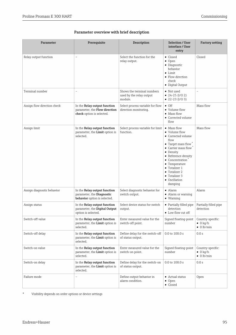
Proline Promass E 300 HART Commissioning
Endress+Hauser 95
Parameter overview with brief description
Parameter Prerequisite Description Selection / Userinterface / User
entry
Factory setting
Relay output function – Select the function for therelay output.
• Closed• Open• Diagnostic
behavior• Limit• Flow direction
check• Digital Output
Closed
Terminal number – Shows the terminal numbersused by the relay outputmodule.
• Not used• 24-25 (I/O 2)• 22-23 (I/O 3)
–
Assign flow direction check In the Relay output functionparameter, the Flow directioncheck option is selected.
Select process variable for flowdirection monitoring.
• Off• Volume flow• Mass flow• Corrected volume
flow
Mass flow
Assign limit In the Relay output functionparameter, the Limit option isselected.
Select process variable for limitfunction.
• Mass flow• Volume flow• Corrected volume
flow• Target mass flow *
• Carrier mass flow *
• Density• Reference density• Concentration *
• Temperature• Totalizer 1• Totalizer 2• Totalizer 3• Oscillation
damping
Mass flow
Assign diagnostic behavior In the Relay output functionparameter, the Diagnosticbehavior option is selected.
Select diagnostic behavior forswitch output.
• Alarm• Alarm or warning• Warning
Alarm
Assign status In the Relay output functionparameter, the Digital Outputoption is selected.
Select device status for switchoutput.
• Partially filled pipedetection
• Low flow cut off
Partially filled pipedetection
Switch-off value In the Relay output functionparameter, the Limit option isselected.
Enter measured value for theswitch-off point.
Signed floating-pointnumber
Country-specific:• 0 kg/h• 0 lb/min
Switch-off delay In the Relay output functionparameter, the Limit option isselected.
Define delay for the switch-offof status output.
0.0 to 100.0 s 0.0 s
Switch-on value In the Relay output functionparameter, the Limit option isselected.
Enter measured value for theswitch-on point.
Signed floating-pointnumber
Country-specific:• 0 kg/h• 0 lb/min
Switch-on delay In the Relay output functionparameter, the Limit option isselected.
Define delay for the switch-onof status output.
0.0 to 100.0 s 0.0 s
Failure mode – Define output behavior inalarm condition.
• Actual status• Open• Closed
Open
* Visibility depends on order options or device settings
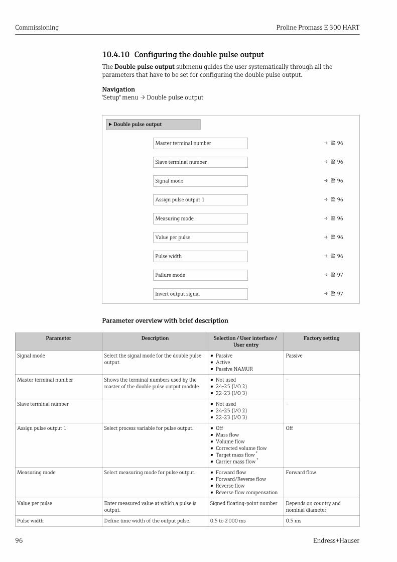
Commissioning Proline Promass E 300 HART
96 Endress+Hauser
10.4.10 Configuring the double pulse outputThe Double pulse output submenu guides the user systematically through all theparameters that have to be set for configuring the double pulse output.
Navigation"Setup" menu → Double pulse output
‣ Double pulse output
Master terminal number → 96
Slave terminal number → 96
Signal mode → 96
Assign pulse output 1 → 96
Measuring mode → 96
Value per pulse → 96
Pulse width → 96
Failure mode → 97
Invert output signal → 97
Parameter overview with brief description
Parameter Description Selection / User interface / User entry
Factory setting
Signal mode Select the signal mode for the double pulseoutput.
• Passive• Active• Passive NAMUR
Passive
Master terminal number Shows the terminal numbers used by themaster of the double pulse output module.
• Not used• 24-25 (I/O 2)• 22-23 (I/O 3)
–
Slave terminal number • Not used• 24-25 (I/O 2)• 22-23 (I/O 3)
–
Assign pulse output 1 Select process variable for pulse output. • Off• Mass flow• Volume flow• Corrected volume flow• Target mass flow *
• Carrier mass flow *
Off
Measuring mode Select measuring mode for pulse output. • Forward flow• Forward/Reverse flow• Reverse flow• Reverse flow compensation
Forward flow
Value per pulse Enter measured value at which a pulse isoutput.
Signed floating-point number Depends on country andnominal diameter
Pulse width Define time width of the output pulse. 0.5 to 2 000 ms 0.5 ms
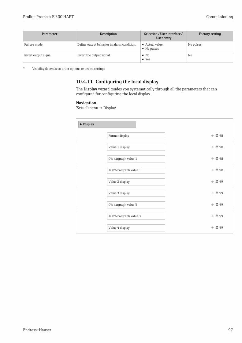
Proline Promass E 300 HART Commissioning
Endress+Hauser 97
Parameter Description Selection / User interface / User entry
Factory setting
Failure mode Define output behavior in alarm condition. • Actual value• No pulses
No pulses
Invert output signal Invert the output signal. • No• Yes
No
* Visibility depends on order options or device settings
10.4.11 Configuring the local displayThe Display wizard guides you systematically through all the parameters that canconfigured for configuring the local display.
Navigation"Setup" menu → Display
‣ Display
Format display → 98
Value 1 display → 98
0% bargraph value 1 → 98
100% bargraph value 1 → 98
Value 2 display → 99
Value 3 display → 99
0% bargraph value 3 → 99
100% bargraph value 3 → 99
Value 4 display → 99
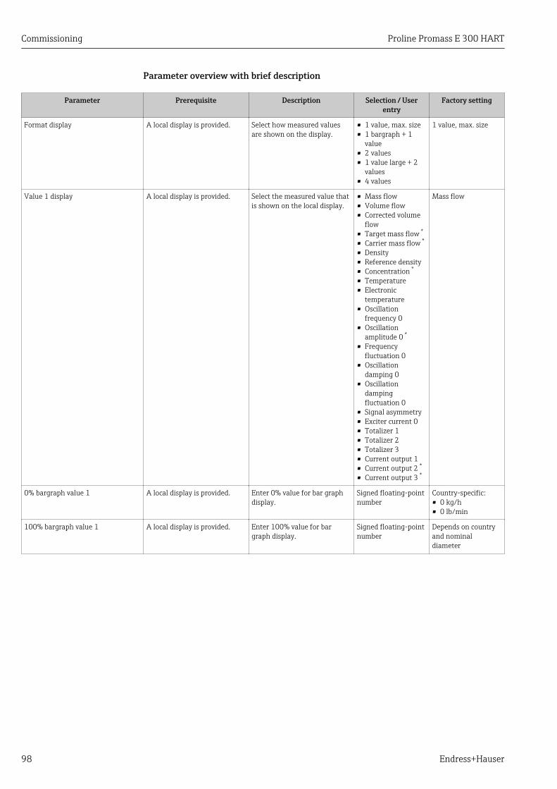
Commissioning Proline Promass E 300 HART
98 Endress+Hauser
Parameter overview with brief description
Parameter Prerequisite Description Selection / Userentry
Factory setting
Format display A local display is provided. Select how measured valuesare shown on the display.
• 1 value, max. size• 1 bargraph + 1
value• 2 values• 1 value large + 2
values• 4 values
1 value, max. size
Value 1 display A local display is provided. Select the measured value thatis shown on the local display.
• Mass flow• Volume flow• Corrected volume
flow• Target mass flow *
• Carrier mass flow *
• Density• Reference density• Concentration *
• Temperature• Electronic
temperature• Oscillation
frequency 0• Oscillation
amplitude 0 *
• Frequencyfluctuation 0
• Oscillationdamping 0
• Oscillationdampingfluctuation 0
• Signal asymmetry• Exciter current 0• Totalizer 1• Totalizer 2• Totalizer 3• Current output 1• Current output 2 *
• Current output 3 *
Mass flow
0% bargraph value 1 A local display is provided. Enter 0% value for bar graphdisplay.
Signed floating-pointnumber
Country-specific:• 0 kg/h• 0 lb/min
100% bargraph value 1 A local display is provided. Enter 100% value for bargraph display.
Signed floating-pointnumber
Depends on countryand nominaldiameter

Proline Promass E 300 HART Commissioning
Endress+Hauser 99
Parameter Prerequisite Description Selection / Userentry
Factory setting
Value 2 display A local display is provided. Select the measured value thatis shown on the local display.
• None• Mass flow• Volume flow• Corrected volume
flow• Target mass flow *
• Carrier mass flow *
• Density• Reference density• Concentration *
• Temperature• Electronic
temperature• Oscillation
frequency 0• Oscillation
amplitude 0 *
• Frequencyfluctuation 0
• Oscillationdamping 0
• Oscillationdampingfluctuation 0
• Signal asymmetry• Exciter current 0• Totalizer 1• Totalizer 2• Totalizer 3• Current output 1• Current output 2 *
• Current output 3 *
None
Value 3 display A local display is provided. Select the measured value thatis shown on the local display.
For the picklist, seethe Value 2 displayparameter (→ 99)
None
0% bargraph value 3 A selection was made in theValue 3 display parameter.
Enter 0% value for bar graphdisplay.
Signed floating-pointnumber
Country-specific:• 0 kg/h• 0 lb/min
100% bargraph value 3 A selection was made in theValue 3 display parameter.
Enter 100% value for bargraph display.
Signed floating-pointnumber
0
Value 4 display A local display is provided. Select the measured value thatis shown on the local display.
For the picklist, seethe Value 2 displayparameter (→ 99)
None
* Visibility depends on order options or device settings

Commissioning Proline Promass E 300 HART
100 Endress+Hauser
10.4.12 Configuring the low flow cut offThe Low flow cut off wizard systematically guides the user through all the parametersthat must be set to configure low flow cut off.
Navigation"Setup" menu → Low flow cut off
‣ Low flow cut off
Assign process variable → 100
On value low flow cutoff → 100
Off value low flow cutoff → 100
Pressure shock suppression → 100
Parameter overview with brief description
Parameter Prerequisite Description Selection / Userentry
Factory setting
Assign process variable – Select process variable for lowflow cut off.
• Off• Mass flow• Volume flow• Corrected volume
flow
Mass flow
On value low flow cutoff One of the following options isselected in the Assign processvariable parameter(→ 100):• Mass flow• Volume flow• Corrected volume flow
Enter on value for low flow cutoff.
Positive floating-point number
Depends on countryand nominaldiameter
Off value low flow cutoff One of the following options isselected in the Assign processvariable parameter(→ 100):• Mass flow• Volume flow• Corrected volume flow
Enter off value for low flow cutoff.
0 to 100.0 % 50 %
Pressure shock suppression One of the following options isselected in the Assign processvariable parameter(→ 100):• Mass flow• Volume flow• Corrected volume flow
Enter time frame for signalsuppression (= active pressureshock suppression).
0 to 100 s 0 s

Proline Promass E 300 HART Commissioning
Endress+Hauser 101
10.4.13 Configuring the partial filled pipe detectionThe Partial filled pipe detection wizard guides you systematically through all parametersthat have to be set for configuring the monitoring of the pipe filling.
Navigation"Setup" menu → Partially filled pipe detection
‣ Partially filled pipe detection
Assign process variable → 101
Low value partial filled pipe detection → 101
High value partial filled pipe detection → 101
Response time part. filled pipe detect. → 101
Parameter overview with brief description
Parameter Prerequisite Description Selection / Userentry
Factory setting
Assign process variable – Select process variable forpartially filled pipe detection.
• Off• Density• Reference density
Off
Low value partial filled pipedetection
One of the following options isselected in the Assign processvariable parameter(→ 101):• Density• Reference density
Enter lower limit value fordeactivating partialy filled pipedetection.
Signed floating-pointnumber
200
High value partial filled pipedetection
One of the following options isselected in the Assign processvariable parameter(→ 101):• Density• Reference density
Enter upper limit value fordeactivating partialy filled pipedetection.
Signed floating-pointnumber
6 000
Response time part. filled pipedetect.
One of the following options isselected in the Assign processvariable parameter(→ 101):• Density• Reference density
Enter time before diagnosticmessage is displayed forpartially filled pipe detection.
0 to 100 s 1 s
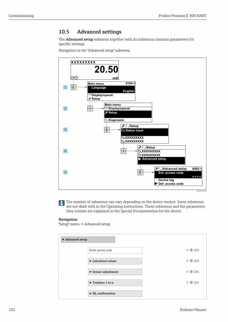
Commissioning Proline Promass E 300 HART
102 Endress+Hauser
10.5 Advanced settingsThe Advanced setup submenu together with its submenus contains parameters forspecific settings.
Navigation to the "Advanced setup" submenu
X X X X X X XX X
20.50
0104-1
0092-1
****
XXXXXXXXX
XXXXXXXXX
XXXXXXXXX
XXXXXXXXX
mA
1.
2.
3.
4.
5.
Display/operat.
Setup
Diagnostic
Display/operat.
Setup
Main menu
English
Main menu
Status input
/ ../Setup
/ ../Setup
Advanced setup
Ent. access code
/ ../Advanced setup
Def. access code
Device tag
Language
A0029564-EN
The number of submenus can vary depending on the device version. Some submenusare not dealt with in the Operating Instructions. These submenus and the parametersthey contain are explained in the Special Documentation for the device.
Navigation"Setup" menu → Advanced setup
‣ Advanced setup
Enter access code → 103
‣ Calculated values → 103
‣ Sensor adjustment → 104
‣ Totalizer 1 to n → 105
‣ SIL confirmation
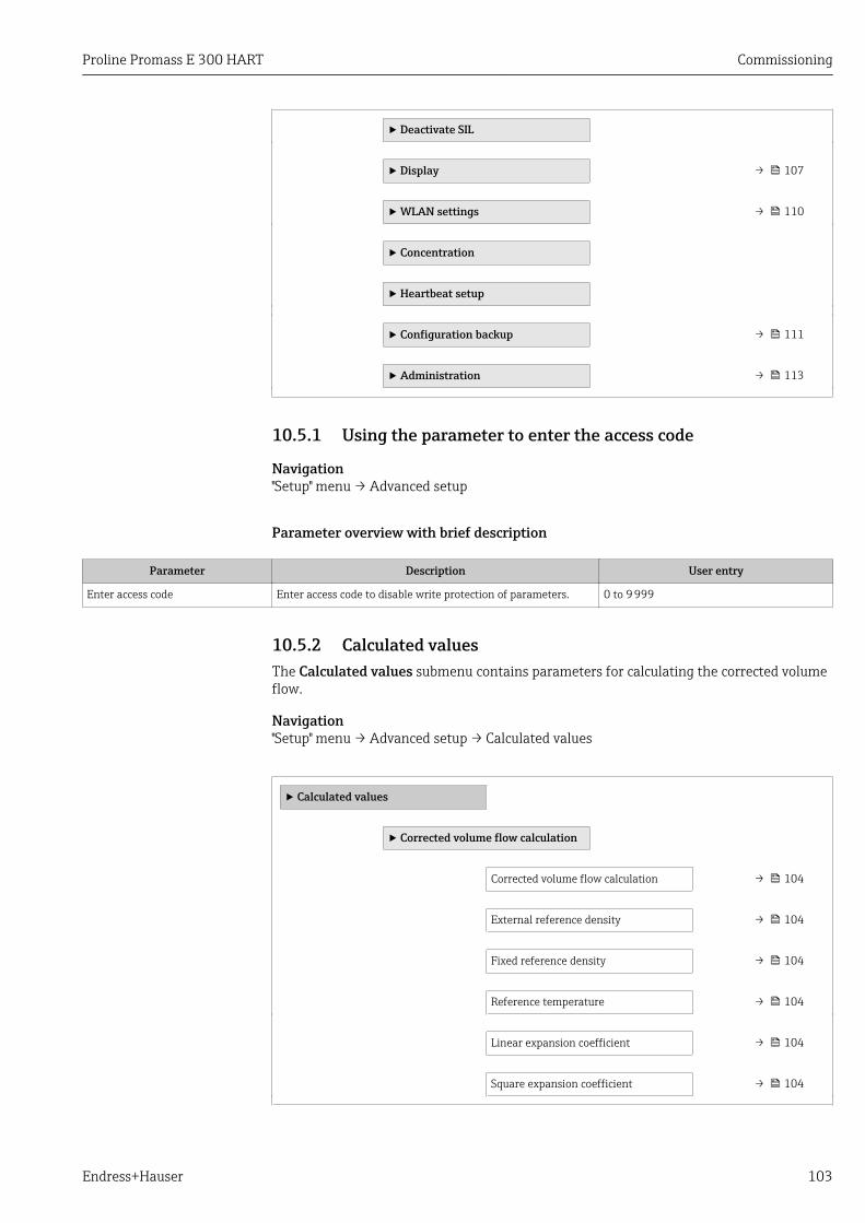
Proline Promass E 300 HART Commissioning
Endress+Hauser 103
‣ Deactivate SIL
‣ Display → 107
‣ WLAN settings → 110
‣ Concentration
‣ Heartbeat setup
‣ Configuration backup → 111
‣ Administration → 113
10.5.1 Using the parameter to enter the access code
Navigation"Setup" menu → Advanced setup
Parameter overview with brief description
Parameter Description User entry
Enter access code Enter access code to disable write protection of parameters. 0 to 9 999
10.5.2 Calculated valuesThe Calculated values submenu contains parameters for calculating the corrected volumeflow.
Navigation"Setup" menu → Advanced setup → Calculated values
‣ Calculated values
‣ Corrected volume flow calculation
Corrected volume flow calculation → 104
External reference density → 104
Fixed reference density → 104
Reference temperature → 104
Linear expansion coefficient → 104
Square expansion coefficient → 104

Commissioning Proline Promass E 300 HART
104 Endress+Hauser
Parameter overview with brief description
Parameter Prerequisite Description Selection / Userinterface / User
entry
Factory setting
Corrected volume flow calculation – Select reference density forcalculating the correctedvolume flow.
• Fixed referencedensity
• Calculatedreference density
• Reference densityby API table 53
• Current input 1 *
• Current input 2 *
Calculated referencedensity
External reference density One of the following options isselected in the Correctedvolume flow calculationparameter:• Current input 1 *
• Current input 2 *
Shows external referencedensity.
Floating pointnumber with sign
–
Fixed reference density The Fixed reference densityoption is selected in theCorrected volume flowcalculation parameterparameter.
Enter fixed value for referencedensity.
Positive floating-point number
1 kg/Nl
Reference temperature The Calculated referencedensity option is selected inthe Corrected volume flowcalculation parameterparameter.
Enter reference temperaturefor calculating the referencedensity.
–273.15 to 99 999 °C Country-specific:• +20 °C• +68 °F
Linear expansion coefficient The Calculated referencedensity option is selected inthe Corrected volume flowcalculation parameterparameter.
Enter linear, medium-specificexpansion coefficient forcalculating the referencedensity.
Signed floating-pointnumber
0.0
Square expansion coefficient The Calculated referencedensity option is selected inthe Corrected volume flowcalculation parameterparameter.
For media with a non-linearexpansion pattern: enter thequadratic, medium-specificexpansion coefficient forcalculating the referencedensity.
Signed floating-pointnumber
0.0
* Visibility depends on order options or device settings
10.5.3 Carrying out a sensor adjustmentThe Sensor adjustment submenu contains parameters that pertain to the functionality ofthe sensor.
Navigation"Setup" menu → Advanced setup → Sensor adjustment
‣ Sensor adjustment
Installation direction → 105
‣ Zero point adjustment → 105
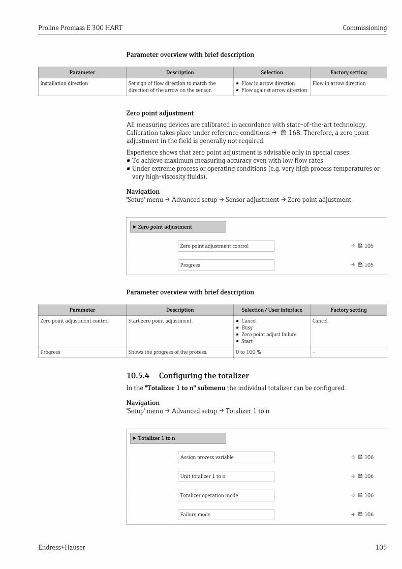
Proline Promass E 300 HART Commissioning
Endress+Hauser 105
Parameter overview with brief description
Parameter Description Selection Factory setting
Installation direction Set sign of flow direction to match thedirection of the arrow on the sensor.
• Flow in arrow direction• Flow against arrow direction
Flow in arrow direction
Zero point adjustment All measuring devices are calibrated in accordance with state-of-the-art technology.Calibration takes place under reference conditions → 168. Therefore, a zero pointadjustment in the field is generally not required.
Experience shows that zero point adjustment is advisable only in special cases:• To achieve maximum measuring accuracy even with low flow rates• Under extreme process or operating conditions (e.g. very high process temperatures or
very high-viscosity fluids).
Navigation"Setup" menu → Advanced setup → Sensor adjustment → Zero point adjustment
‣ Zero point adjustment
Zero point adjustment control → 105
Progress → 105
Parameter overview with brief description
Parameter Description Selection / User interface Factory setting
Zero point adjustment control Start zero point adjustment. • Cancel• Busy• Zero point adjust failure• Start
Cancel
Progress Shows the progress of the process. 0 to 100 % –
10.5.4 Configuring the totalizerIn the "Totalizer 1 to n" submenu the individual totalizer can be configured.
Navigation"Setup" menu → Advanced setup → Totalizer 1 to n
‣ Totalizer 1 to n
Assign process variable → 106
Unit totalizer 1 to n → 106
Totalizer operation mode → 106
Failure mode → 106
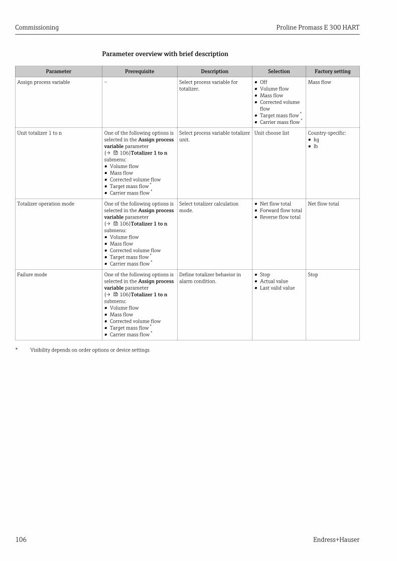
Commissioning Proline Promass E 300 HART
106 Endress+Hauser
Parameter overview with brief description
Parameter Prerequisite Description Selection Factory setting
Assign process variable – Select process variable fortotalizer.
• Off• Volume flow• Mass flow• Corrected volume
flow• Target mass flow *
• Carrier mass flow *
Mass flow
Unit totalizer 1 to n One of the following options isselected in the Assign processvariable parameter(→ 106)Totalizer 1 to nsubmenu:• Volume flow• Mass flow• Corrected volume flow• Target mass flow *
• Carrier mass flow *
Select process variable totalizerunit.
Unit choose list Country-specific:• kg• lb
Totalizer operation mode One of the following options isselected in the Assign processvariable parameter(→ 106)Totalizer 1 to nsubmenu:• Volume flow• Mass flow• Corrected volume flow• Target mass flow *
• Carrier mass flow *
Select totalizer calculationmode.
• Net flow total• Forward flow total• Reverse flow total
Net flow total
Failure mode One of the following options isselected in the Assign processvariable parameter(→ 106)Totalizer 1 to nsubmenu:• Volume flow• Mass flow• Corrected volume flow• Target mass flow *
• Carrier mass flow *
Define totalizer behavior inalarm condition.
• Stop• Actual value• Last valid value
Stop
* Visibility depends on order options or device settings
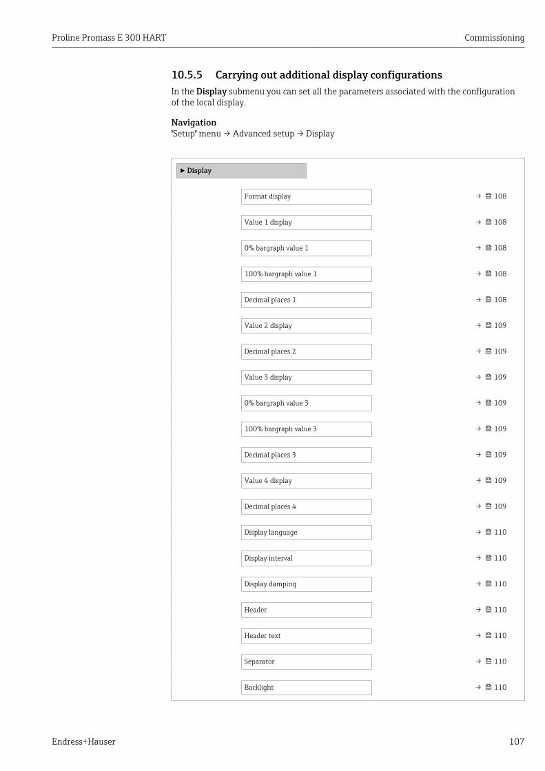
Proline Promass E 300 HART Commissioning
Endress+Hauser 107
10.5.5 Carrying out additional display configurationsIn the Display submenu you can set all the parameters associated with the configurationof the local display.
Navigation"Setup" menu → Advanced setup → Display
‣ Display
Format display → 108
Value 1 display → 108
0% bargraph value 1 → 108
100% bargraph value 1 → 108
Decimal places 1 → 108
Value 2 display → 109
Decimal places 2 → 109
Value 3 display → 109
0% bargraph value 3 → 109
100% bargraph value 3 → 109
Decimal places 3 → 109
Value 4 display → 109
Decimal places 4 → 109
Display language → 110
Display interval → 110
Display damping → 110
Header → 110
Header text → 110
Separator → 110
Backlight → 110
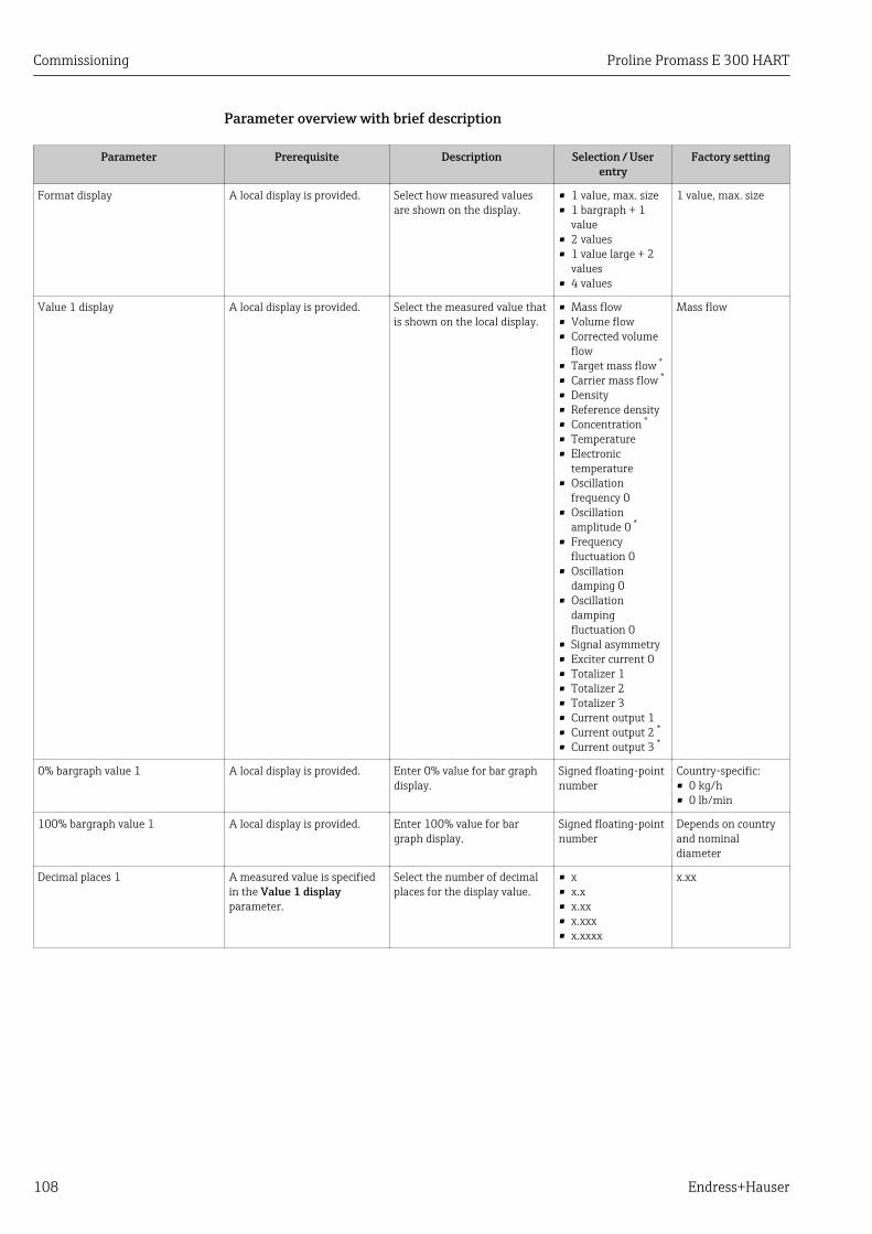
Commissioning Proline Promass E 300 HART
108 Endress+Hauser
Parameter overview with brief description
Parameter Prerequisite Description Selection / Userentry
Factory setting
Format display A local display is provided. Select how measured valuesare shown on the display.
• 1 value, max. size• 1 bargraph + 1
value• 2 values• 1 value large + 2
values• 4 values
1 value, max. size
Value 1 display A local display is provided. Select the measured value thatis shown on the local display.
• Mass flow• Volume flow• Corrected volume
flow• Target mass flow *
• Carrier mass flow *
• Density• Reference density• Concentration *
• Temperature• Electronic
temperature• Oscillation
frequency 0• Oscillation
amplitude 0 *
• Frequencyfluctuation 0
• Oscillationdamping 0
• Oscillationdampingfluctuation 0
• Signal asymmetry• Exciter current 0• Totalizer 1• Totalizer 2• Totalizer 3• Current output 1• Current output 2 *
• Current output 3 *
Mass flow
0% bargraph value 1 A local display is provided. Enter 0% value for bar graphdisplay.
Signed floating-pointnumber
Country-specific:• 0 kg/h• 0 lb/min
100% bargraph value 1 A local display is provided. Enter 100% value for bargraph display.
Signed floating-pointnumber
Depends on countryand nominaldiameter
Decimal places 1 A measured value is specifiedin the Value 1 displayparameter.
Select the number of decimalplaces for the display value.
• x• x.x• x.xx• x.xxx• x.xxxx
x.xx

Proline Promass E 300 HART Commissioning
Endress+Hauser 109
Parameter Prerequisite Description Selection / Userentry
Factory setting
Value 2 display A local display is provided. Select the measured value thatis shown on the local display.
• None• Mass flow• Volume flow• Corrected volume
flow• Target mass flow *
• Carrier mass flow *
• Density• Reference density• Concentration *
• Temperature• Electronic
temperature• Oscillation
frequency 0• Oscillation
amplitude 0 *
• Frequencyfluctuation 0
• Oscillationdamping 0
• Oscillationdampingfluctuation 0
• Signal asymmetry• Exciter current 0• Totalizer 1• Totalizer 2• Totalizer 3• Current output 1• Current output 2 *
• Current output 3 *
None
Decimal places 2 A measured value is specifiedin the Value 2 displayparameter.
Select the number of decimalplaces for the display value.
• x• x.x• x.xx• x.xxx• x.xxxx
x.xx
Value 3 display A local display is provided. Select the measured value thatis shown on the local display.
For the picklist, seethe Value 2 displayparameter (→ 99)
None
0% bargraph value 3 A selection was made in theValue 3 display parameter.
Enter 0% value for bar graphdisplay.
Signed floating-pointnumber
Country-specific:• 0 kg/h• 0 lb/min
100% bargraph value 3 A selection was made in theValue 3 display parameter.
Enter 100% value for bargraph display.
Signed floating-pointnumber
0
Decimal places 3 A measured value is specifiedin the Value 3 displayparameter.
Select the number of decimalplaces for the display value.
• x• x.x• x.xx• x.xxx• x.xxxx
x.xx
Value 4 display A local display is provided. Select the measured value thatis shown on the local display.
For the picklist, seethe Value 2 displayparameter (→ 99)
None
Decimal places 4 A measured value is specifiedin the Value 4 displayparameter.
Select the number of decimalplaces for the display value.
• x• x.x• x.xx• x.xxx• x.xxxx
x.xx
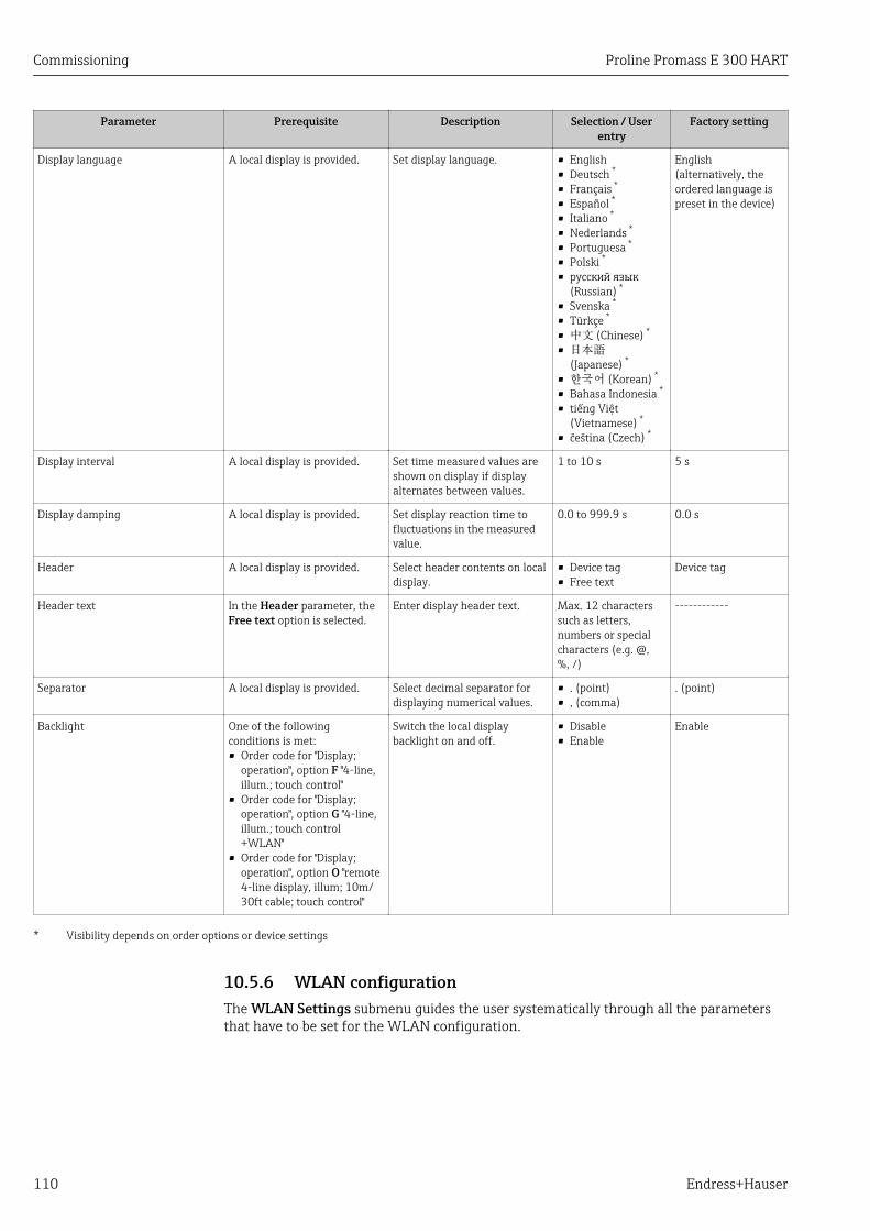
Commissioning Proline Promass E 300 HART
110 Endress+Hauser
Parameter Prerequisite Description Selection / Userentry
Factory setting
Display language A local display is provided. Set display language. • English• Deutsch *
• Français *
• Español *
• Italiano *
• Nederlands *
• Portuguesa *
• Polski *
• русский язык(Russian) *
• Svenska *
• Türkçe *
• 中文 (Chinese) *
• 日本語(Japanese) *
• 한국어 (Korean) *
• Bahasa Indonesia *
• tiếng Việt(Vietnamese) *
• čeština (Czech) *
English(alternatively, theordered language ispreset in the device)
Display interval A local display is provided. Set time measured values areshown on display if displayalternates between values.
1 to 10 s 5 s
Display damping A local display is provided. Set display reaction time tofluctuations in the measuredvalue.
0.0 to 999.9 s 0.0 s
Header A local display is provided. Select header contents on localdisplay.
• Device tag• Free text
Device tag
Header text In the Header parameter, theFree text option is selected.
Enter display header text. Max. 12 characterssuch as letters,numbers or specialcharacters (e.g. @,%, /)
------------
Separator A local display is provided. Select decimal separator fordisplaying numerical values.
• . (point)• , (comma)
. (point)
Backlight One of the followingconditions is met:• Order code for "Display;
operation", option F "4-line,illum.; touch control"
• Order code for "Display;operation", option G "4-line,illum.; touch control+WLAN"
• Order code for "Display;operation", option O "remote4-line display, illum; 10m/30ft cable; touch control"
Switch the local displaybacklight on and off.
• Disable• Enable
Enable
* Visibility depends on order options or device settings
10.5.6 WLAN configurationThe WLAN Settings submenu guides the user systematically through all the parametersthat have to be set for the WLAN configuration.

Proline Promass E 300 HART Commissioning
Endress+Hauser 111
Navigation"Setup" menu → Advanced setup → WLAN Settings
‣ WLAN settings
WLAN IP address → 111
Security type → 111
WLAN passphrase → 111
Assign SSID name → 111
SSID name → 111
Apply changes → 111
Parameter overview with brief description
Parameter Prerequisite Description User entry / Selection
Factory setting
WLAN IP address – Enter IP address of the deviceWLAN interface.
4 octet: 0 to 255 (inthe particular octet)
192.168.1.212
Security type – Select the security type of theWLAN interface.
• Unsecured• WPA2-PSK
WPA2-PSK
WLAN passphrase In the Security typeparameter, the WPA2-PSKoption is selected.
Enter the network key (8 to 32characters).
The network keysupplied with the deviceshould be changedduring commissioningfor security reasons.
8 to 32-digitcharacter stringcomprising numbers,letters and specialcharacters
Serial number of themeasuring device(e.g. L100A802000)
Assign SSID name – Select which name will be usedfor SSID: device tag or user-defined name.
• Device tag• User-defined
User-defined
SSID name In the Assign SSID nameparameter, the User-definedoption is selected.
Enter the user-defined SSIDname (max. 32 characters).
The user-defined SSIDname may only beassigned once. If the SSIDname is assigned morethan once, the devicescan interfere with oneanother.
Max. 32-digitcharacter stringcomprising numbers,letters and specialcharacters
EH_devicedesignation_last 7digits of the serialnumber (e.g.EH_Promass_300_A802000)
Apply changes – Use changed WLAN settings. • Cancel• Ok
Cancel
10.5.7 Configuration managementAfter commissioning, you can save the current device configurationor restore the previousdevice configuration.
You can do so using the Configuration management parameter and the related optionsfound in the Configuration backup submenu.

Commissioning Proline Promass E 300 HART
112 Endress+Hauser
Navigation"Setup" menu → Advanced setup → Configuration backup
‣ Configuration backup
Operating time → 112
Last backup → 112
Configuration management → 112
Backup state → 112
Comparison result → 112
Parameter overview with brief description
Parameter Description User interface / Selection Factory setting
Operating time Indicates how long the device has been inoperation.
Days (d), hours (h), minutes(m) and seconds (s)
–
Last backup Shows when the last data backup was savedto embedded HistoROM.
Days (d), hours (h), minutes(m) and seconds (s)
–
Configuration management Select action for managing the device data inthe embedded HistoROM.
• Cancel• Execute backup• Restore• Compare• Clear backup data
Cancel
Backup state Shows the current status of data saving orrestoring.
• None• Backup in progress• Restoring in progress• Delete in progress• Compare in progress• Restoring failed• Backup failed
None
Comparison result Comparison of current device data withembedded HistoROM.
• Settings identical• Settings not identical• No backup available• Backup settings corrupt• Check not done• Dataset incompatible
Check not done
Function scope of the "Configuration management" parameter
Options Description
Cancel No action is executed and the user exits the parameter.
Execute backup A backup copy of the current device configuration is saved from the integratedHistoROM to the memory of the device. The backup copy includes the transmitterdata of the device.
Restore The last backup copy of the device configuration is restored from the devicememory to the device's integrated HistoROM. The backup copy includes thetransmitter data of the device.
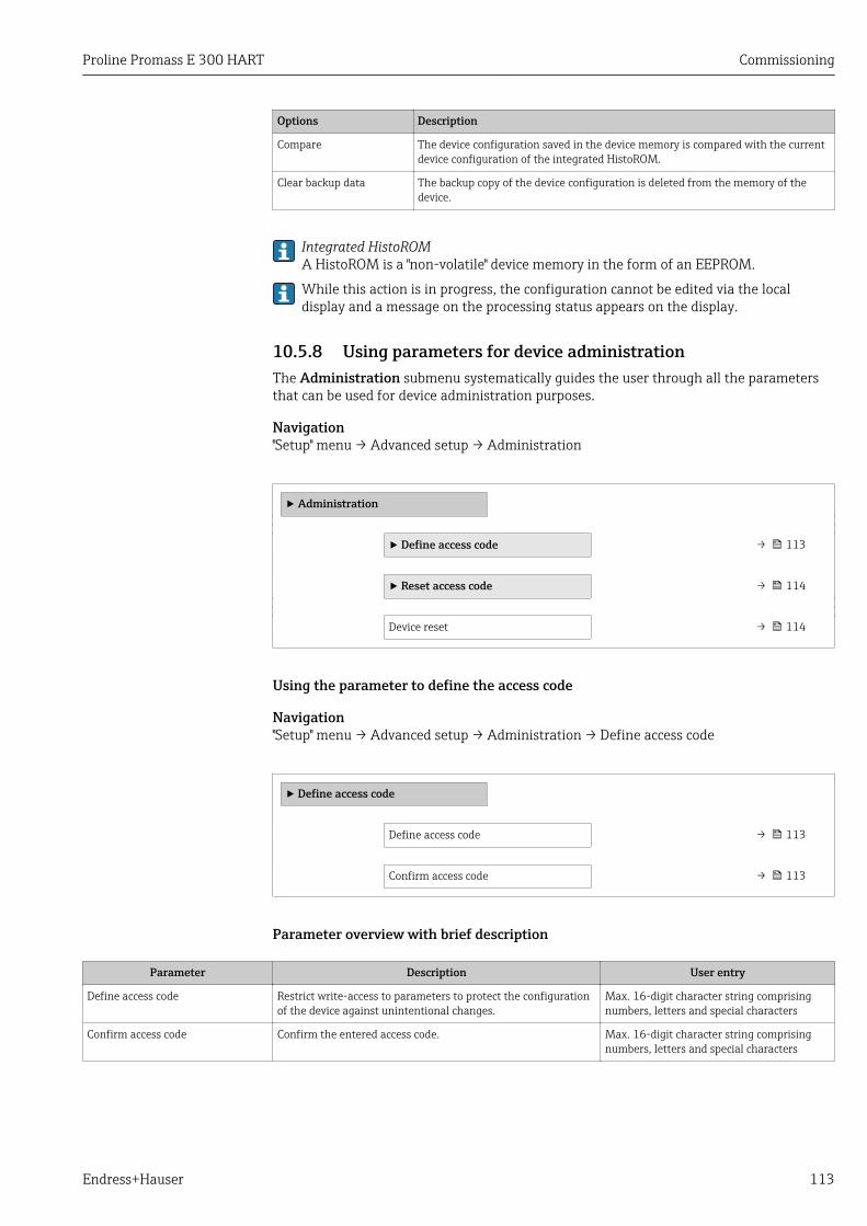
Proline Promass E 300 HART Commissioning
Endress+Hauser 113
Options Description
Compare The device configuration saved in the device memory is compared with the currentdevice configuration of the integrated HistoROM.
Clear backup data The backup copy of the device configuration is deleted from the memory of thedevice.
Integrated HistoROMA HistoROM is a "non-volatile" device memory in the form of an EEPROM.
While this action is in progress, the configuration cannot be edited via the localdisplay and a message on the processing status appears on the display.
10.5.8 Using parameters for device administrationThe Administration submenu systematically guides the user through all the parametersthat can be used for device administration purposes.
Navigation"Setup" menu → Advanced setup → Administration
‣ Administration
‣ Define access code → 113
‣ Reset access code → 114
Device reset → 114
Using the parameter to define the access code
Navigation"Setup" menu → Advanced setup → Administration → Define access code
‣ Define access code
Define access code → 113
Confirm access code → 113
Parameter overview with brief description
Parameter Description User entry
Define access code Restrict write-access to parameters to protect the configurationof the device against unintentional changes.
Max. 16-digit character string comprisingnumbers, letters and special characters
Confirm access code Confirm the entered access code. Max. 16-digit character string comprisingnumbers, letters and special characters

Commissioning Proline Promass E 300 HART
114 Endress+Hauser
Using the parameter to reset the access code
Navigation"Setup" menu → Advanced setup → Administration → Reset access code
‣ Reset access code
Operating time → 114
Reset access code → 114
Parameter overview with brief description
Parameter Description User interface / User entry Factory setting
Operating time Indicates how long the device has been inoperation.
Days (d), hours (h), minutes(m) and seconds (s)
–
Reset access code Reset access code to factory settings.
For a reset code, contact yourEndress+Hauser service organization.
The reset code can only be entered via:• Web browser• DeviceCare, FieldCare (via service
interface CDI-RJ45)• Fieldbus
Character string comprisingnumbers, letters and specialcharacters
0x00
Using the parameter to reset the device
Navigation"Setup" menu → Advanced setup → Administration
Parameter overview with brief description
Parameter Description Selection Factory setting
Device reset Reset the device configuration - eitherentirely or in part - to a defined state.
• Cancel• To delivery settings• Restart device• Restore S-DAT backup
Cancel
10.6 SimulationThe Simulation submenu enables you to simulate, without a real flow situation, variousprocess variables in the process and the device alarm mode and to verify downstreamsignal chains (switching valves or closed-control loops).
Navigation"Diagnostics" menu → Simulation
‣ Simulation
Assign simulation process variable → 116

Proline Promass E 300 HART Commissioning
Endress+Hauser 115
Process variable value → 116
Status input simulation → 116
Input signal level → 116
Current input 1 to n simulation → 116
Value current input 1 to n → 116
Current output 1 to n simulation → 116
Value current output 1 to n → 116
Frequency output simulation 1 to n → 116
Frequency value 1 to n → 116
Pulse output simulation 1 to n → 116
Pulse value 1 to n → 116
Switch output simulation 1 to n → 117
Switch status 1 to n → 117
Relay output 1 to n simulation → 117
Switch status 1 to n → 117
Pulse output simulation → 117
Pulse value → 117
Device alarm simulation → 117
Diagnostic event category → 117
Diagnostic event simulation → 117
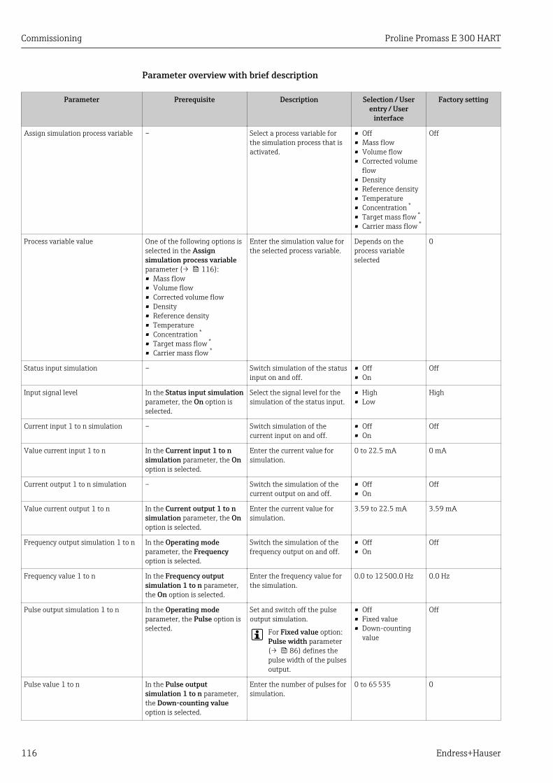
Commissioning Proline Promass E 300 HART
116 Endress+Hauser
Parameter overview with brief description
Parameter Prerequisite Description Selection / Userentry / User
interface
Factory setting
Assign simulation process variable – Select a process variable forthe simulation process that isactivated.
• Off• Mass flow• Volume flow• Corrected volume
flow• Density• Reference density• Temperature• Concentration *
• Target mass flow *
• Carrier mass flow *
Off
Process variable value One of the following options isselected in the Assignsimulation process variableparameter (→ 116):• Mass flow• Volume flow• Corrected volume flow• Density• Reference density• Temperature• Concentration *
• Target mass flow *
• Carrier mass flow *
Enter the simulation value forthe selected process variable.
Depends on theprocess variableselected
0
Status input simulation – Switch simulation of the statusinput on and off.
• Off• On
Off
Input signal level In the Status input simulationparameter, the On option isselected.
Select the signal level for thesimulation of the status input.
• High• Low
High
Current input 1 to n simulation – Switch simulation of thecurrent input on and off.
• Off• On
Off
Value current input 1 to n In the Current input 1 to nsimulation parameter, the Onoption is selected.
Enter the current value forsimulation.
0 to 22.5 mA 0 mA
Current output 1 to n simulation – Switch the simulation of thecurrent output on and off.
• Off• On
Off
Value current output 1 to n In the Current output 1 to nsimulation parameter, the Onoption is selected.
Enter the current value forsimulation.
3.59 to 22.5 mA 3.59 mA
Frequency output simulation 1 to n In the Operating modeparameter, the Frequencyoption is selected.
Switch the simulation of thefrequency output on and off.
• Off• On
Off
Frequency value 1 to n In the Frequency outputsimulation 1 to n parameter,the On option is selected.
Enter the frequency value forthe simulation.
0.0 to 12 500.0 Hz 0.0 Hz
Pulse output simulation 1 to n In the Operating modeparameter, the Pulse option isselected.
Set and switch off the pulseoutput simulation.
For Fixed value option:Pulse width parameter(→ 86) defines thepulse width of the pulsesoutput.
• Off• Fixed value• Down-counting
value
Off
Pulse value 1 to n In the Pulse outputsimulation 1 to n parameter,the Down-counting valueoption is selected.
Enter the number of pulses forsimulation.
0 to 65 535 0
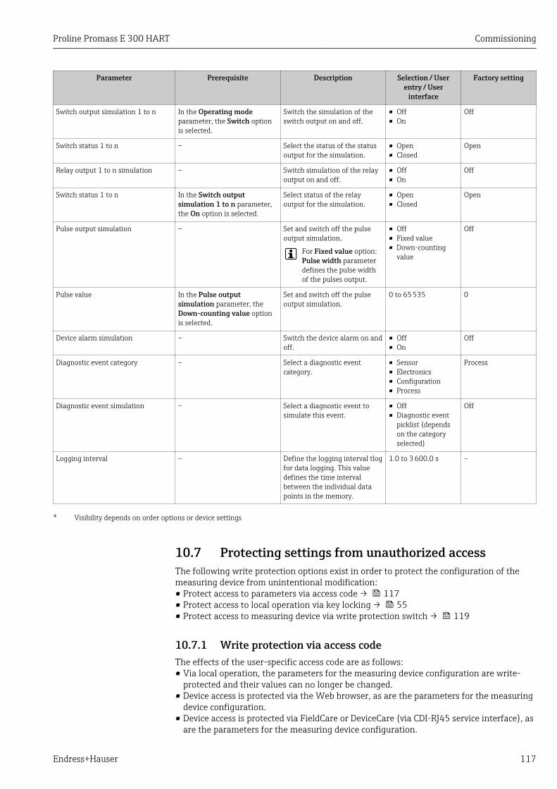
Proline Promass E 300 HART Commissioning
Endress+Hauser 117
Parameter Prerequisite Description Selection / Userentry / User
interface
Factory setting
Switch output simulation 1 to n In the Operating modeparameter, the Switch optionis selected.
Switch the simulation of theswitch output on and off.
• Off• On
Off
Switch status 1 to n – Select the status of the statusoutput for the simulation.
• Open• Closed
Open
Relay output 1 to n simulation – Switch simulation of the relayoutput on and off.
• Off• On
Off
Switch status 1 to n In the Switch outputsimulation 1 to n parameter,the On option is selected.
Select status of the relayoutput for the simulation.
• Open• Closed
Open
Pulse output simulation – Set and switch off the pulseoutput simulation.
For Fixed value option:Pulse width parameterdefines the pulse widthof the pulses output.
• Off• Fixed value• Down-counting
value
Off
Pulse value In the Pulse outputsimulation parameter, theDown-counting value optionis selected.
Set and switch off the pulseoutput simulation.
0 to 65 535 0
Device alarm simulation – Switch the device alarm on andoff.
• Off• On
Off
Diagnostic event category – Select a diagnostic eventcategory.
• Sensor• Electronics• Configuration• Process
Process
Diagnostic event simulation – Select a diagnostic event tosimulate this event.
• Off• Diagnostic event
picklist (dependson the categoryselected)
Off
Logging interval – Define the logging interval tlogfor data logging. This valuedefines the time intervalbetween the individual datapoints in the memory.
1.0 to 3 600.0 s –
* Visibility depends on order options or device settings
10.7 Protecting settings from unauthorized accessThe following write protection options exist in order to protect the configuration of themeasuring device from unintentional modification:• Protect access to parameters via access code → 117• Protect access to local operation via key locking → 55• Protect access to measuring device via write protection switch → 119
10.7.1 Write protection via access codeThe effects of the user-specific access code are as follows:• Via local operation, the parameters for the measuring device configuration are write-
protected and their values can no longer be changed.• Device access is protected via the Web browser, as are the parameters for the measuring
device configuration.• Device access is protected via FieldCare or DeviceCare (via CDI-RJ45 service interface), as
are the parameters for the measuring device configuration.
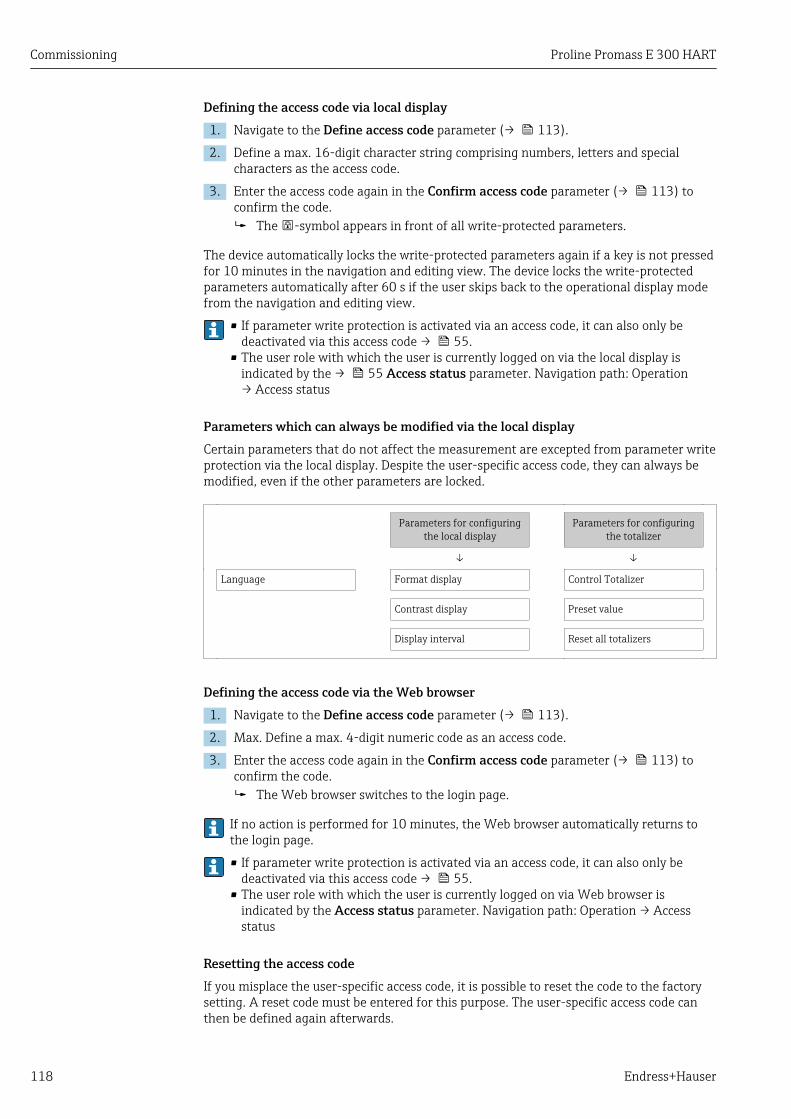
Commissioning Proline Promass E 300 HART
118 Endress+Hauser
Defining the access code via local display1. Navigate to the Define access code parameter (→ 113).
2. Define a max. 16-digit character string comprising numbers, letters and specialcharacters as the access code.
3. Enter the access code again in the Confirm access code parameter (→ 113) toconfirm the code. The -symbol appears in front of all write-protected parameters.
The device automatically locks the write-protected parameters again if a key is not pressedfor 10 minutes in the navigation and editing view. The device locks the write-protectedparameters automatically after 60 s if the user skips back to the operational display modefrom the navigation and editing view.
• If parameter write protection is activated via an access code, it can also only bedeactivated via this access code → 55.
• The user role with which the user is currently logged on via the local display isindicated by the → 55 Access status parameter. Navigation path: Operation→ Access status
Parameters which can always be modified via the local displayCertain parameters that do not affect the measurement are excepted from parameter writeprotection via the local display. Despite the user-specific access code, they can always bemodified, even if the other parameters are locked.
Parameters for configuringthe local display
Parameters for configuringthe totalizer
↓ ↓
Language Format display Control Totalizer
Contrast display Preset value
Display interval Reset all totalizers
Defining the access code via the Web browser1. Navigate to the Define access code parameter (→ 113).
2. Max. Define a max. 4-digit numeric code as an access code.
3. Enter the access code again in the Confirm access code parameter (→ 113) toconfirm the code. The Web browser switches to the login page.
If no action is performed for 10 minutes, the Web browser automatically returns tothe login page.
• If parameter write protection is activated via an access code, it can also only bedeactivated via this access code → 55.
• The user role with which the user is currently logged on via Web browser isindicated by the Access status parameter. Navigation path: Operation → Accessstatus
Resetting the access codeIf you misplace the user-specific access code, it is possible to reset the code to the factorysetting. A reset code must be entered for this purpose. The user-specific access code canthen be defined again afterwards.

Proline Promass E 300 HART Commissioning
Endress+Hauser 119
Via Web browser, FieldCare, DeviceCare (via CDI-RJ45 service interface), fieldbusFor a reset code, contact your Endress+Hauser service organization.
1. Navigate to the Reset access code parameter (→ 114).
2. Enter the reset code. The access code has been reset to the factory setting 0000. It can be redefined
→ 118.
10.7.2 Write protection via write protection switchUnlike parameter write protection via a user-specific access code, this allows write accessto the entire operating menu - except for the "Contrast display" parameter - to be locked.
The parameter values are now read only and cannot be edited any more (exception"Contrast display" parameter):• Via local display• Via HART protocol
1.
OnOff
1
2
3
4
A0029630
Setting the write protection (WP) switch on the main electronics module to the ONposition enables hardware write protection. In the Locking status parameter the Hardware locked option is displayed
→ 120. In addition, on the local display the -symbol appears in front of theparameters in the header of the operational display and in the navigation view.
X X X X X X XX X
20.50XXXX
A0029425
2. Setting the write protection (WP) switch on the main electronics module to the OFFposition (factory setting) disables hardware write protection. No option is displayed in the Locking status parameter → 120. On the local
display, the -symbol disappears from in front of the parameters in the headerof the operational display and in the navigation view.

Operation Proline Promass E 300 HART
120 Endress+Hauser
11 Operation
11.1 Reading the device locking statusDevice active write protection: Locking status parameter
Operation → Locking status
Function scope of the "Locking status" parameter
Options Description
None The access status displayed in the Access status parameter applies → 55. Onlyappears on local display.
Hardware locked The DIP switch for hardware locking is activated on the PCB board. This locks writeaccess to the parameters (e.g. via local display or operating tool).
SIL locked The SIL mode is enabled. This locks write access to the parameters (e.g. via localdisplay or operating tool).
Temporarily locked Write access to the parameters is temporarily locked on account of internalprocesses running in the device (e.g. data upload/download, reset etc.). Once theinternal processing has been completed, the parameters can be changed onceagain.
11.2 Adjusting the operating languageDetailed information:• To configure the operating language → 73• For information on the operating languages supported by the measuring device
→ 177
11.3 Configuring the displayDetailed information:• On the basic settings for the local display → 97• On the advanced settings for the local display → 107
11.4 Reading measured valuesWith the Measured values submenu, it is possible to read all the measured values.
Navigation"Diagnostics" menu → Measured values
‣ Measured values
‣ Measured variables → 121
‣ Input values → 123
‣ Output values → 124
‣ Totalizer → 122
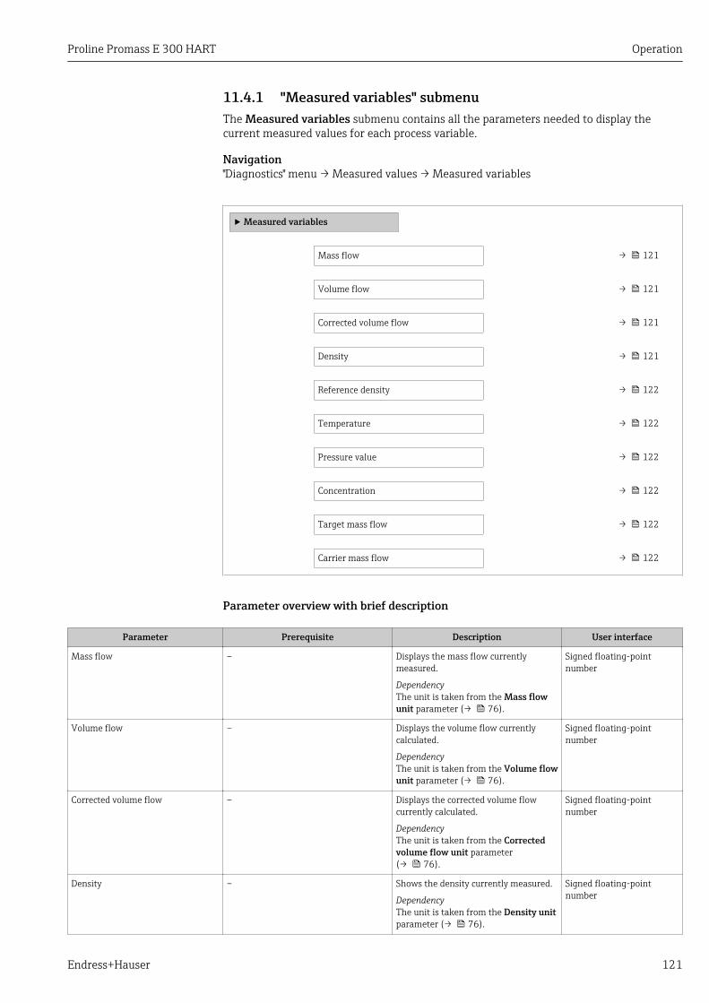
Proline Promass E 300 HART Operation
Endress+Hauser 121
11.4.1 "Measured variables" submenuThe Measured variables submenu contains all the parameters needed to display thecurrent measured values for each process variable.
Navigation"Diagnostics" menu → Measured values → Measured variables
‣ Measured variables
Mass flow → 121
Volume flow → 121
Corrected volume flow → 121
Density → 121
Reference density → 122
Temperature → 122
Pressure value → 122
Concentration → 122
Target mass flow → 122
Carrier mass flow → 122
Parameter overview with brief description
Parameter Prerequisite Description User interface
Mass flow – Displays the mass flow currentlymeasured.
DependencyThe unit is taken from the Mass flowunit parameter (→ 76).
Signed floating-pointnumber
Volume flow – Displays the volume flow currentlycalculated.
DependencyThe unit is taken from the Volume flowunit parameter (→ 76).
Signed floating-pointnumber
Corrected volume flow – Displays the corrected volume flowcurrently calculated.
DependencyThe unit is taken from the Correctedvolume flow unit parameter(→ 76).
Signed floating-pointnumber
Density – Shows the density currently measured.
DependencyThe unit is taken from the Density unitparameter (→ 76).
Signed floating-pointnumber
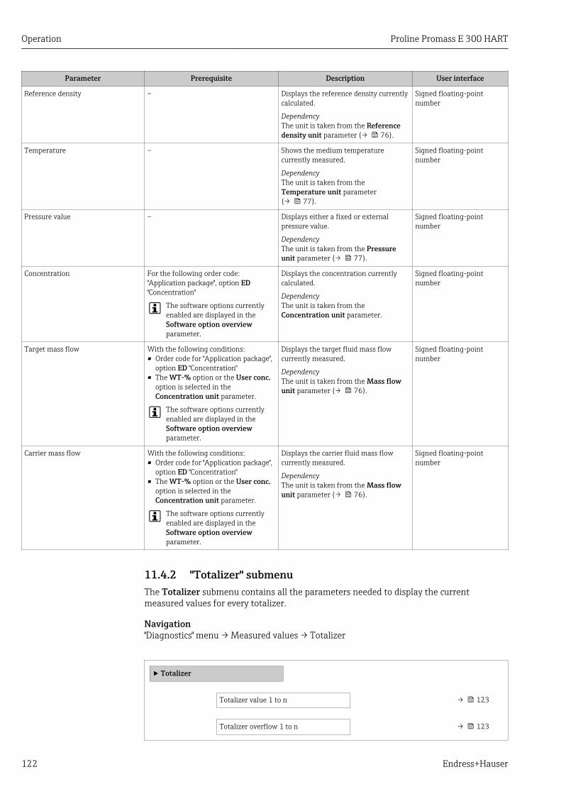
Operation Proline Promass E 300 HART
122 Endress+Hauser
Parameter Prerequisite Description User interface
Reference density – Displays the reference density currentlycalculated.
DependencyThe unit is taken from the Referencedensity unit parameter (→ 76).
Signed floating-pointnumber
Temperature – Shows the medium temperaturecurrently measured.
DependencyThe unit is taken from theTemperature unit parameter(→ 77).
Signed floating-pointnumber
Pressure value – Displays either a fixed or externalpressure value.
DependencyThe unit is taken from the Pressureunit parameter (→ 77).
Signed floating-pointnumber
Concentration For the following order code:"Application package", option ED"Concentration"
The software options currentlyenabled are displayed in theSoftware option overviewparameter.
Displays the concentration currentlycalculated.
DependencyThe unit is taken from theConcentration unit parameter.
Signed floating-pointnumber
Target mass flow With the following conditions:• Order code for "Application package",
option ED "Concentration"• The WT-% option or the User conc.
option is selected in theConcentration unit parameter.
The software options currentlyenabled are displayed in theSoftware option overviewparameter.
Displays the target fluid mass flowcurrently measured.
DependencyThe unit is taken from the Mass flowunit parameter (→ 76).
Signed floating-pointnumber
Carrier mass flow With the following conditions:• Order code for "Application package",
option ED "Concentration"• The WT-% option or the User conc.
option is selected in theConcentration unit parameter.
The software options currentlyenabled are displayed in theSoftware option overviewparameter.
Displays the carrier fluid mass flowcurrently measured.
DependencyThe unit is taken from the Mass flowunit parameter (→ 76).
Signed floating-pointnumber
11.4.2 "Totalizer" submenuThe Totalizer submenu contains all the parameters needed to display the currentmeasured values for every totalizer.
Navigation"Diagnostics" menu → Measured values → Totalizer
‣ Totalizer
Totalizer value 1 to n → 123
Totalizer overflow 1 to n → 123

Proline Promass E 300 HART Operation
Endress+Hauser 123
Parameter overview with brief description
Parameter Prerequisite Description User interface
Totalizer value 1 to n A process variable is selected in theAssign process variable parameter(→ 106) of the Totalizer 1 to nsubmenu.
Displays the current totalizer countervalue.
Signed floating-pointnumber
Totalizer overflow 1 to n A process variable is selected in theAssign process variable parameter(→ 106) of the Totalizer 1 to nsubmenu.
Displays the current totalizer overflow. Integer with sign
11.4.3 "Input values" submenuThe Input values submenu guides you systematically to the individual input values.
Navigation"Diagnostics" menu → Measured values → Input values
‣ Input values
‣ Current input 1 to n → 123
‣ Status input 1 to n → 123
Input values of current inputThe Current input 1 to n submenu contains all the parameters needed to display thecurrent measured values for every current input.
Navigation"Diagnostics" menu → Measured values → Input values → Current input 1 to n
‣ Current input 1 to n
Measured values 1 to n → 123
Measured current 1 to n → 123
Parameter overview with brief description
Parameter Description User interface
Measured values 1 to n Displays the current input value. Signed floating-point number
Measured current 1 to n Displays the current value of the current input. 0 to 22.5 mA
Input values of status inputThe Status input 1 to n submenu contains all the parameters needed to display thecurrent measured values for every status input.

Operation Proline Promass E 300 HART
124 Endress+Hauser
Navigation"Diagnostics" menu → Measured values → Input values → Status input 1 to n
‣ Status input 1 to n
Value status input → 124
Parameter overview with brief description
Parameter Description User interface
Value status input Shows the current input signal level. • High• Low
11.4.4 Output valuesThe Output values submenu contains all the parameters needed to display the currentmeasured values for every output.
Navigation"Diagnostics" menu → Measured values → Output values
‣ Output values
‣ Current output 1 to n → 124
‣ Pulse/frequency/switch output 1to n
→ 125
‣ Relay output 1 to n → 125
‣ Double pulse output → 126
Output values of current outputThe Value current output submenu contains all the parameters needed to display thecurrent measured values for every current output.
Navigation"Diagnostics" menu → Measured values → Output values → Value current output 1 to n
‣ Current output 1 to n
Output current 1 to n → 125
Measured current 1 to n → 125

Proline Promass E 300 HART Operation
Endress+Hauser 125
Parameter overview with brief description
Parameter Description User interface
Output current 1 Displays the current value currently calculated for the currentoutput.
3.59 to 22.5 mA
Measured current Displays the current value currently measured for the currentoutput.
0 to 30 mA
Output values for pulse/frequency/switch outputThe Pulse/frequency/switch output 1 to n submenu contains all the parameters neededto display the current measured values for every pulse/frequency/switch output.
Navigation"Diagnostics" menu → Measured values → Output values → Pulse/frequency/switch output1 to n
‣ Pulse/frequency/switch output 1to n
Output frequency 1 to n → 125
Pulse output 1 to n
Switch status 1 to n → 125
Parameter overview with brief description
Parameter Prerequisite Description User interface / Userentry
Factory setting
Output frequency In the Operating modeparameter, the Frequencyoption is selected.
Displays the value currentlymeasured for the frequencyoutput.
0.0 to 12 500.0 Hz –
Value per pulse In the Operating modeparameter, the Pulse option isselected and one of thefollowing options is selected inthe Assign pulse outputparameter (→ 86):• Mass flow• Volume flow• Corrected volume flow• Target mass flow *
• Carrier mass flow *
Enter measured value at whicha pulse is output.
Signed floating-pointnumber
Depends on countryand nominaldiameter
Switch status The Switch option is selectedin the Operating modeparameter.
Displays the current switchoutput status.
• Open• Closed
–
* Visibility depends on order options or device settings
Output values for relay outputThe Relay output 1 to n submenu contains all the parameters needed to display thecurrent measured values for every relay output.

Operation Proline Promass E 300 HART
126 Endress+Hauser
Navigation"Diagnostics" menu → Measured values → Output values → Relay output 1 to n
‣ Relay output 1 to n
Switch status → 126
Switch cycles → 126
Max. switch cycles number → 126
Parameter overview with brief description
Parameter Description User interface
Switch status Shows the current relay switch status. • Open• Closed
Switch cycles Shows number of all performed switch cycles. Positive integer
Max. switch cycles number Shows the maximal number of guaranteed switch cycles. Positive integer
Output values for double pulse outputThe Double pulse output submenu contains all the parameters needed to display thecurrent measured values for every double pulse output.
Navigation"Diagnostics" menu → Measured values → Output values → Double pulse output
‣ Double pulse output
Pulse output → 126
Parameter overview with brief description
Parameter Description User interface
Pulse output Shows the currently output pulse frequency. Positive floating-point number
11.5 Adapting the measuring device to the processconditions
The following are available for this purpose:• Basic settings using theSetup menu (→ 73)• Advanced settings using theAdvanced setup submenu (→ 102)
11.6 Performing a totalizer resetThe totalizers are reset in the Operation submenu:• Control Totalizer• Reset all totalizers
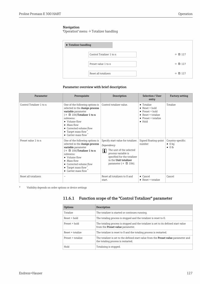
Proline Promass E 300 HART Operation
Endress+Hauser 127
Navigation"Operation" menu → Totalizer handling
‣ Totalizer handling
Control Totalizer 1 to n → 127
Preset value 1 to n → 127
Reset all totalizers → 127
Parameter overview with brief description
Parameter Prerequisite Description Selection / Userentry
Factory setting
Control Totalizer 1 to n One of the following options isselected in the Assign processvariable parameter(→ 106)Totalizer 1 to nsubmenu:• Volume flow• Mass flow• Corrected volume flow• Target mass flow *
• Carrier mass flow *
Control totalizer value. • Totalize• Reset + hold• Preset + hold• Reset + totalize• Preset + totalize• Hold
Totalize
Preset value 1 to n One of the following options isselected in the Assign processvariable parameter(→ 106)Totalizer 1 to nsubmenu:• Volume flow• Mass flow• Corrected volume flow• Target mass flow *
• Carrier mass flow *
Specify start value for totalizer.
Dependency
The unit of the selectedprocess variable isspecified for the totalizerin the Unit totalizerparameter (→ 106).
Signed floating-pointnumber
Country-specific:• 0 kg• 0 lb
Reset all totalizers – Reset all totalizers to 0 andstart.
• Cancel• Reset + totalize
Cancel
* Visibility depends on order options or device settings
11.6.1 Function scope of the "Control Totalizer" parameter
Options Description
Totalize The totalizer is started or continues running.
Reset + hold The totaling process is stopped and the totalizer is reset to 0.
Preset + hold The totaling process is stopped and the totalizer is set to its defined start valuefrom the Preset value parameter.
Reset + totalize The totalizer is reset to 0 and the totaling process is restarted.
Preset + totalize The totalizer is set to the defined start value from the Preset value parameter andthe totaling process is restarted.
Hold Totalizing is stopped.
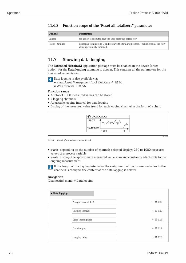
Operation Proline Promass E 300 HART
128 Endress+Hauser
11.6.2 Function scope of the "Reset all totalizers" parameter
Options Description
Cancel No action is executed and the user exits the parameter.
Reset + totalize Resets all totalizers to 0 and restarts the totaling process. This deletes all the flowvalues previously totalized.
11.7 Showing data loggingThe Extended HistoROM application package must be enabled in the device (orderoption) for the Data logging submenu to appear. This contains all the parameters for themeasured value history.
Data logging is also available via:• Plant Asset Management Tool FieldCare → 65.• Web browser→ 56
Function range• A total of 1000 measured values can be stored• 4 logging channels• Adjustable logging interval for data logging• Display of the measured value trend for each logging channel in the form of a chart
A0016357
30 Chart of a measured value trend
• x-axis: depending on the number of channels selected displays 250 to 1000 measuredvalues of a process variable.
• y-axis: displays the approximate measured value span and constantly adapts this to theongoing measurement.
If the length of the logging interval or the assignment of the process variables to thechannels is changed, the content of the data logging is deleted.
Navigation"Diagnostics" menu → Data logging
‣ Data logging
Assign channel 1...4 → 129
Logging interval → 129
Clear logging data → 129
Data logging → 129
Logging delay → 129

Proline Promass E 300 HART Operation
Endress+Hauser 129
Data logging control → 129
Data logging status → 130
Entire logging duration → 130
Parameter overview with brief description
Parameter Prerequisite Description Selection / Userentry / User
interface
Factory setting
Assign channel 1 to n The Extended HistoROMapplication package isavailable.
Assign process variable tologging channel.
• Off• Mass flow• Volume flow• Corrected volume
flow• Target mass flow *
• Carrier mass flow *
• Density• Reference density• Concentration *
• Temperature• Electronic
temperature• Oscillation
frequency 0• Frequency
fluctuation 0• Oscillation
amplitude *
• Oscillationdamping 0
• Oscillationdampingfluctuation 0
• Signal asymmetry• Exciter current 0• Current output 1• Current output 2 *
• Current output 3 *
• Current output 4 *
Off
Logging interval The Extended HistoROMapplication package isavailable.
Define the logging interval fordata logging. This valuedefines the time intervalbetween the individual datapoints in the memory.
0.1 to 999.0 s 1.0 s
Clear logging data The Extended HistoROMapplication package isavailable.
Clear the entire logging data. • Cancel• Clear data
Cancel
Data logging – Select the data loggingmethod.
• Overwriting• Not overwriting
Overwriting
Logging delay In the Data loggingparameter, the Notoverwriting option is selected.
Enter the time delay formeasured value logging.
0 to 999 h 0 h
Data logging control In the Data loggingparameter, the Notoverwriting option is selected.
Start and stop measured valuelogging.
• None• Delete + start• Stop
None

Operation Proline Promass E 300 HART
130 Endress+Hauser
Parameter Prerequisite Description Selection / Userentry / User
interface
Factory setting
Data logging status In the Data loggingparameter, the Notoverwriting option is selected.
Displays the measured valuelogging status.
• Done• Delay active• Active• Stopped
Done
Entire logging duration In the Data loggingparameter, the Notoverwriting option is selected.
Displays the total loggingduration.
Positive floating-point number
0 s
* Visibility depends on order options or device settings
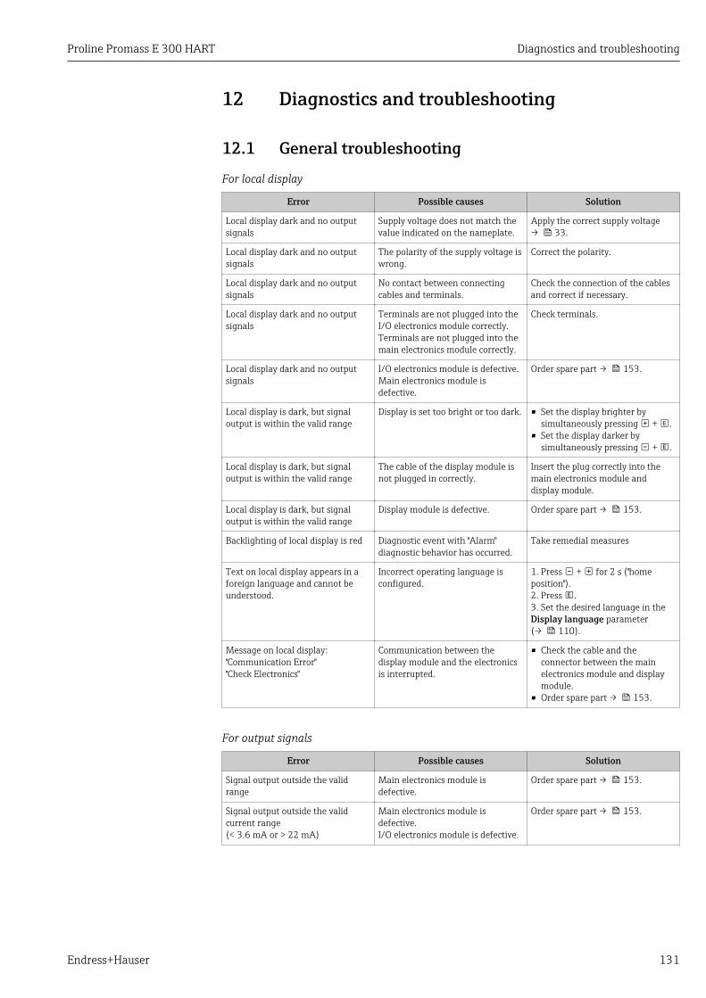
Proline Promass E 300 HART Diagnostics and troubleshooting
Endress+Hauser 131
12 Diagnostics and troubleshooting
12.1 General troubleshooting
For local display
Error Possible causes Solution
Local display dark and no outputsignals
Supply voltage does not match thevalue indicated on the nameplate.
Apply the correct supply voltage→ 33.
Local display dark and no outputsignals
The polarity of the supply voltage iswrong.
Correct the polarity.
Local display dark and no outputsignals
No contact between connectingcables and terminals.
Check the connection of the cablesand correct if necessary.
Local display dark and no outputsignals
Terminals are not plugged into theI/O electronics module correctly.Terminals are not plugged into themain electronics module correctly.
Check terminals.
Local display dark and no outputsignals
I/O electronics module is defective.Main electronics module isdefective.
Order spare part → 153.
Local display is dark, but signaloutput is within the valid range
Display is set too bright or too dark. • Set the display brighter bysimultaneously pressing + .
• Set the display darker bysimultaneously pressing + .
Local display is dark, but signaloutput is within the valid range
The cable of the display module isnot plugged in correctly.
Insert the plug correctly into themain electronics module anddisplay module.
Local display is dark, but signaloutput is within the valid range
Display module is defective. Order spare part → 153.
Backlighting of local display is red Diagnostic event with "Alarm"diagnostic behavior has occurred.
Take remedial measures
Text on local display appears in aforeign language and cannot beunderstood.
Incorrect operating language isconfigured.
1. Press + for 2 s ("homeposition").2. Press .3. Set the desired language in theDisplay language parameter(→ 110).
Message on local display:"Communication Error""Check Electronics"
Communication between thedisplay module and the electronicsis interrupted.
• Check the cable and theconnector between the mainelectronics module and displaymodule.
• Order spare part → 153.
For output signals
Error Possible causes Solution
Signal output outside the validrange
Main electronics module isdefective.
Order spare part → 153.
Signal output outside the validcurrent range(< 3.6 mA or > 22 mA)
Main electronics module isdefective.I/O electronics module is defective.
Order spare part → 153.
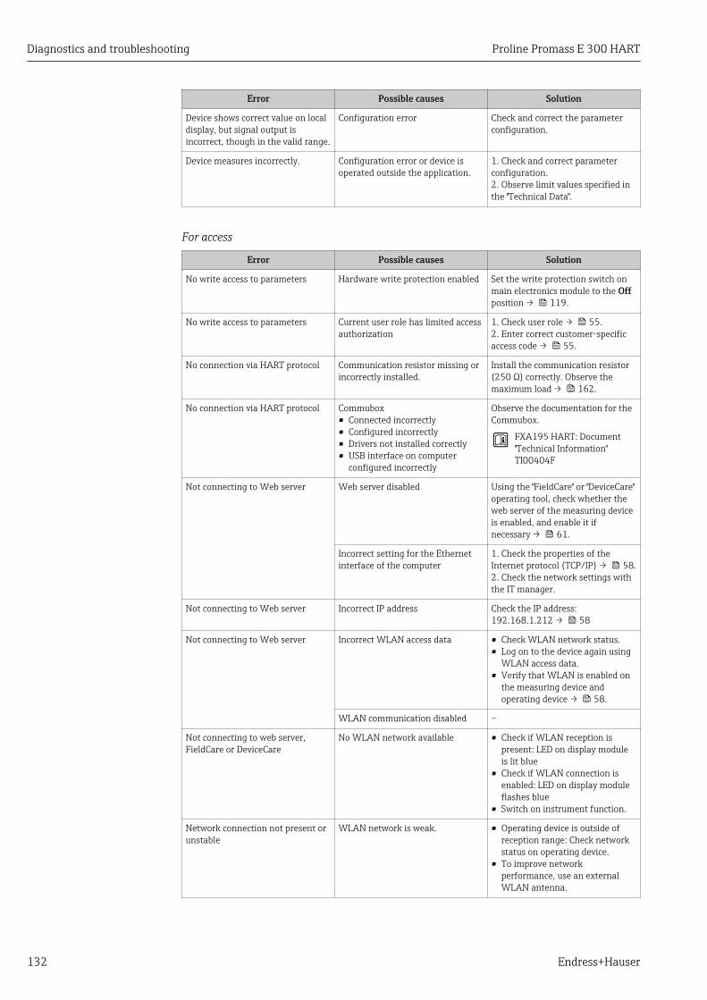
Diagnostics and troubleshooting Proline Promass E 300 HART
132 Endress+Hauser
Error Possible causes Solution
Device shows correct value on localdisplay, but signal output isincorrect, though in the valid range.
Configuration error Check and correct the parameterconfiguration.
Device measures incorrectly. Configuration error or device isoperated outside the application.
1. Check and correct parameterconfiguration.2. Observe limit values specified inthe "Technical Data".
For access
Error Possible causes Solution
No write access to parameters Hardware write protection enabled Set the write protection switch onmain electronics module to the Offposition → 119.
No write access to parameters Current user role has limited accessauthorization
1. Check user role → 55.2. Enter correct customer-specificaccess code → 55.
No connection via HART protocol Communication resistor missing orincorrectly installed.
Install the communication resistor(250 Ω) correctly. Observe themaximum load → 162.
No connection via HART protocol Commubox• Connected incorrectly• Configured incorrectly• Drivers not installed correctly• USB interface on computer
configured incorrectly
Observe the documentation for theCommubox.
FXA195 HART: Document"Technical Information"TI00404F
Not connecting to Web server Web server disabled Using the "FieldCare" or "DeviceCare"operating tool, check whether theweb server of the measuring deviceis enabled, and enable it ifnecessary → 61.
Incorrect setting for the Ethernetinterface of the computer
1. Check the properties of theInternet protocol (TCP/IP) → 58.2. Check the network settings withthe IT manager.
Not connecting to Web server Incorrect IP address Check the IP address:192.168.1.212 → 58
Not connecting to Web server Incorrect WLAN access data • Check WLAN network status.• Log on to the device again using
WLAN access data.• Verify that WLAN is enabled on
the measuring device andoperating device → 58.
WLAN communication disabled –
Not connecting to web server,FieldCare or DeviceCare
No WLAN network available • Check if WLAN reception ispresent: LED on display moduleis lit blue
• Check if WLAN connection isenabled: LED on display moduleflashes blue
• Switch on instrument function.
Network connection not present orunstable
WLAN network is weak. • Operating device is outside ofreception range: Check networkstatus on operating device.
• To improve networkperformance, use an externalWLAN antenna.

Proline Promass E 300 HART Diagnostics and troubleshooting
Endress+Hauser 133
Error Possible causes Solution
Parallel WLAN and Ethernetcommunication
• Check network settings.• Temporarily enable only the
WLAN as an interface.
Web browser frozen and operationno longer possible
Data transfer active Wait until data transfer or currentaction is finished.
Connection lost 1. Check cable connection andpower supply.2. Refresh the Web browser andrestart if necessary.
Content of Web browserincomplete or difficult to read
Not using optimum version of Webserver.
1. Use the correct Web browserversion .2. Clear the Web browser cache andrestart the Web browser.
Unsuitable view settings. Change the font size/display ratioof the Web browser.
No or incomplete display ofcontents in the Web browser
• JavaScript not enabled• JavaScript cannot be enabled
1. Enable JavaScript.2. Enter http://XXX.XXX.X.XXX/basic.html as the IP address.
Operation with FieldCare orDeviceCare via CDI-RJ45 serviceinterface (port 8000)
Firewall of computer or network ispreventing communication
Depending on the settings of thefirewall used on the computer or inthe network, the firewall must beadapted or disabled to allowFieldCare/DeviceCare access.
Flashing of firmware with FieldCareor DeviceCare via CDI-RJ45 serviceinterface (via port 8000 or TFTPports)
Firewall of computer or network ispreventing communication
Depending on the settings of thefirewall used on the computer or inthe network, the firewall must beadapted or disabled to allowFieldCare/DeviceCare access.
12.2 Diagnostic information via light emitting diodes
12.2.1 TransmitterDifferent LEDs in the transmitter provide information on the device status.
1 2 3 4 5
A0029629
1 Supply voltage2 Device status3 Not used4 Communication5 Service interface (CDI) active
LED Color Meaning
1 Supply voltage Green Supply voltage is ok
Off Supply voltage is off or too low
2 Device status Red Error

Diagnostics and troubleshooting Proline Promass E 300 HART
134 Endress+Hauser
LED Color Meaning
Flashing red Warning
3 Not used – –
4 Communication White Communication active
5 Service interface (CDI) Yellow Connection established
Flashing yellow Communication active
Off No connection
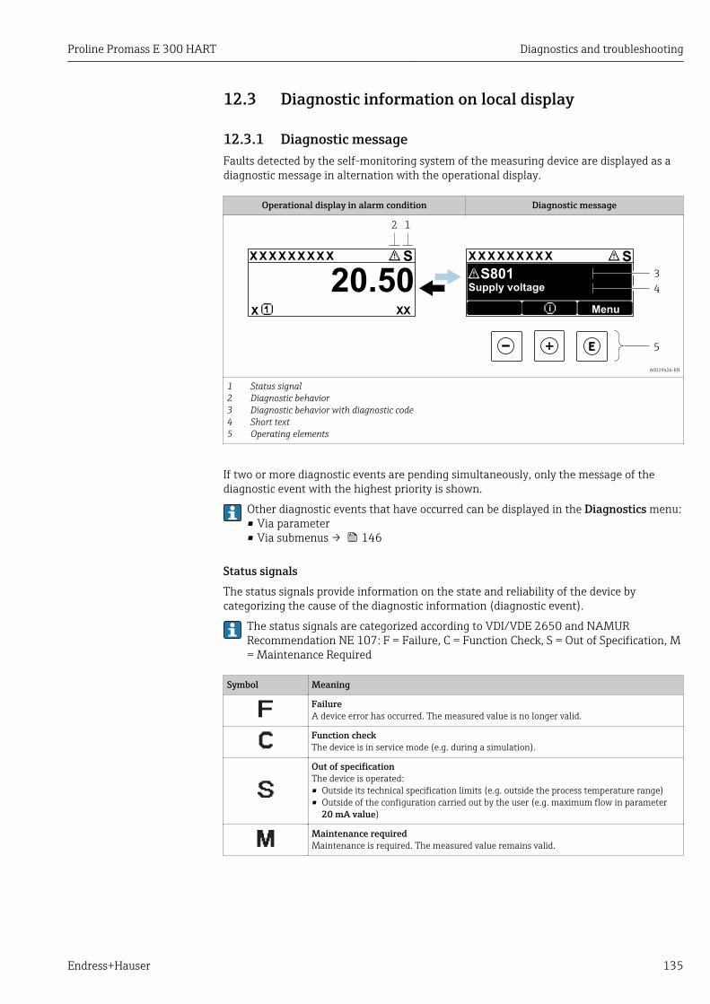
Proline Promass E 300 HART Diagnostics and troubleshooting
Endress+Hauser 135
12.3 Diagnostic information on local display
12.3.1 Diagnostic messageFaults detected by the self-monitoring system of the measuring device are displayed as adiagnostic message in alternation with the operational display.
Operational display in alarm condition Diagnostic message
1
4
3
X X X X X X XX X X X X X X X XX X
2
S S
XX
20.50
5
X i
S801
Menu
Supply voltage
A0029426-EN
12345
Status signalDiagnostic behaviorDiagnostic behavior with diagnostic codeShort textOperating elements
If two or more diagnostic events are pending simultaneously, only the message of thediagnostic event with the highest priority is shown.
Other diagnostic events that have occurred can be displayed in the Diagnostics menu:• Via parameter• Via submenus → 146
Status signalsThe status signals provide information on the state and reliability of the device bycategorizing the cause of the diagnostic information (diagnostic event).
The status signals are categorized according to VDI/VDE 2650 and NAMURRecommendation NE 107: F = Failure, C = Function Check, S = Out of Specification, M= Maintenance Required
Symbol Meaning
FailureA device error has occurred. The measured value is no longer valid.
Function checkThe device is in service mode (e.g. during a simulation).
Out of specificationThe device is operated:• Outside its technical specification limits (e.g. outside the process temperature range)• Outside of the configuration carried out by the user (e.g. maximum flow in parameter
20 mA value)
Maintenance requiredMaintenance is required. The measured value remains valid.
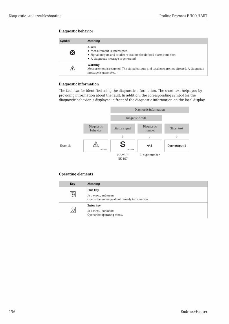
Diagnostics and troubleshooting Proline Promass E 300 HART
136 Endress+Hauser
Diagnostic behavior
Symbol Meaning
Alarm• Measurement is interrupted.• Signal outputs and totalizers assume the defined alarm condition.• A diagnostic message is generated.
WarningMeasurement is resumed. The signal outputs and totalizers are not affected. A diagnosticmessage is generated.
Diagnostic informationThe fault can be identified using the diagnostic information. The short text helps you byproviding information about the fault. In addition, the corresponding symbol for thediagnostic behavior is displayed in front of the diagnostic information on the local display.
Diagnostic information
Diagnostic code
Diagnosticbehavior Status signal Diagnostic
number Short text
↓ ↓ ↓
Example A0013962 A0013958
441 Curr.output 1
NAMURNE 107
3-digit number
Operating elements
Key Meaning
Plus key
In a menu, submenuOpens the message about remedy information.
Enter key
In a menu, submenuOpens the operating menu.

Proline Promass E 300 HART Diagnostics and troubleshooting
Endress+Hauser 137
12.3.2 Calling up remedial measures
X X X X X X XX X X X X X X X XX XS S
XX
20.50X i
S801
Menu
S
(ID:203)
S801 0d00h02m25s
1
2
4
6
3
5
1.
2.
3.
Increase supply voltage
S801 Supply voltage
Diagnostic list
Diagnostics 1
Diagnostics 2Diagnostics 3
Supply voltage
Supply voltage
A0029431-EN
31 Message for remedial measures
1 Diagnostic information2 Short text3 Service ID4 Diagnostic behavior with diagnostic code5 Operation time of occurrence6 Remedial measures
The user is in the diagnostic message.
1. Press ( symbol). The Diagnostic list submenu opens.
2. Select the desired diagnostic event with or and press . The message for the remedial measures for the selected diagnostic event opens.
3. Press + simultaneously. The message for the remedial measures closes.
The user is in the Diagnostics menu at an entry for a diagnostics event, e.g. in theDiagnostic list submenu or Previous diagnostics parameter.
1. Press . The message for the remedial measures for the selected diagnostic event opens.
2. Press + simultaneously. The message for the remedial measures closes.
12.4 Diagnostic information in the Web browser
12.4.1 Diagnostic optionsAny faults detected by the measuring device are displayed in the Web browser on thehome page once the user has logged on.
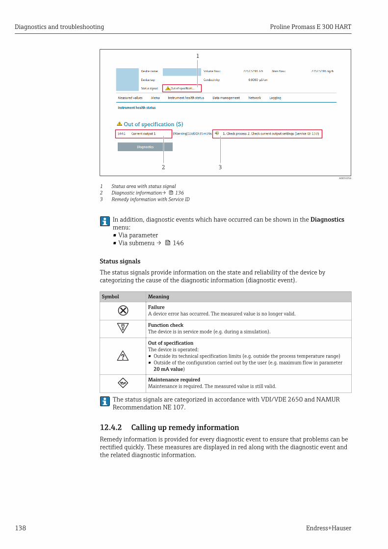
Diagnostics and troubleshooting Proline Promass E 300 HART
138 Endress+Hauser
2 3
1
A0031056
1 Status area with status signal2 Diagnostic information→ 1363 Remedy information with Service ID
In addition, diagnostic events which have occurred can be shown in the Diagnosticsmenu:• Via parameter• Via submenu → 146
Status signalsThe status signals provide information on the state and reliability of the device bycategorizing the cause of the diagnostic information (diagnostic event).
Symbol Meaning
FailureA device error has occurred. The measured value is no longer valid.
Function checkThe device is in service mode (e.g. during a simulation).
Out of specificationThe device is operated:• Outside its technical specification limits (e.g. outside the process temperature range)• Outside of the configuration carried out by the user (e.g. maximum flow in parameter
20 mA value)
Maintenance requiredMaintenance is required. The measured value is still valid.
The status signals are categorized in accordance with VDI/VDE 2650 and NAMURRecommendation NE 107.
12.4.2 Calling up remedy informationRemedy information is provided for every diagnostic event to ensure that problems can berectified quickly. These measures are displayed in red along with the diagnostic event andthe related diagnostic information.

Proline Promass E 300 HART Diagnostics and troubleshooting
Endress+Hauser 139
12.5 Diagnostic information in DeviceCare or FieldCare
12.5.1 Diagnostic optionsAny faults detected by the measuring device are displayed on the home page of theoperating tool once the connection has been established.
Xxxxxx/…/…/
Xxxxxx
P
P
P
+
+
+
+Diagnostics 1:
Remedy information:
Failure (F)
Function check (C)
Out of spezification (S)
Maintenance required (M)
C485 Simulation measured vari...
Deactivate Simulation (Service...
Diagnostics 1: C485 Simu...
Remedy information: Deactivate...
Access status tooling: Mainenance
Operation
Setup
Diagnostics
Expert
Function check (C)Status signal:
Device tag:
Device name: Mass flow:
Volume flow:Xxxxxxx
12.34 kg/h
12.34 m /h³
Xxxxxxx
1
2
3
A0021799-EN
1 Status area with status signal→ 1352 Diagnostic information→ 1363 Remedy information with Service ID
In addition, diagnostic events which have occurred can be shown in the Diagnosticsmenu:• Via parameter• Via submenu → 146
Diagnostic informationThe fault can be identified using the diagnostic information. The short text helps you byproviding information about the fault. In addition, the corresponding symbol for thediagnostic behavior is displayed in front of the diagnostic information on the local display.
Diagnostic information
Diagnostic code
Diagnosticbehavior Status signal Diagnostic
number Short text
↓ ↓ ↓
Example A0013962 A0013958
441 Curr.output 1
NAMURNE 107
3-digit number

Diagnostics and troubleshooting Proline Promass E 300 HART
140 Endress+Hauser
12.5.2 Calling up remedy informationRemedy information is provided for every diagnostic event to ensure that problems can berectified quickly:• On the home page
Remedy information is displayed in a separate field below the diagnostics information.• In the Diagnostics menu
Remedy information can be called up in the working area of the user interface.
The user is in the Diagnostics menu.
1. Call up the desired parameter.
2. On the right in the working area, mouse over the parameter. A tool tip with remedy information for the diagnostic event appears.
12.6 Adapting the diagnostic information
12.6.1 Adapting the diagnostic behaviorEach item of diagnostic information is assigned a specific diagnostic behavior at thefactory. The user can change this assignment for specific diagnostic information in theDiagnostic behavior submenu.
Expert → System → Diagnostic handling → Diagnostic behavior
0723-1
Diagnostic no. 044
/ ../Diagn. behavior
Diagnostic no. 801
Diagnostic no. 274Warning
A0014048-EN
32 Taking the example of the local display
You can assign the following options to the diagnostic number as the diagnostic behavior:
Options Description
Alarm The device stops measurement. The signal outputs and totalizers assume the definedalarm condition. A diagnostic message is generated.The background lighting changes to red.
Warning The device continues to measure. The signal outputs and totalizers are not affected. Adiagnostic message is generated.
Logbook entry only The device continues to measure. The diagnostic message is displayed only in the Eventlogbook submenu (Event list submenu) and is not displayed in alternation with theoperational display.
Off The diagnostic event is ignored, and no diagnostic message is generated or entered.
12.6.2 Adapting the status signalEach item of diagnostic information is assigned a specific status signal at the factory. Theuser can change this assignment for specific diagnostic information in the Diagnosticevent category submenu.
Expert → Communication → Diagnostic event category

Proline Promass E 300 HART Diagnostics and troubleshooting
Endress+Hauser 141
Available status signalsConfiguration as per HART 7 Specification (Condensed Status), in accordance withNAMUR NE107.
Symbol Meaning
A0013956
FailureA device error is present. The measured value is no longer valid.
A0013959
Function checkThe device is in service mode (e.g. during a simulation).
A0013958
Out of specificationThe device is being operated:• Outside its technical specification limits (e.g. outside the process temperature range)• Outside of the configuration carried out by the user (e.g. maximum flow in parameter
20 mA value)
A0013957
Maintenance requiredMaintenance is required. The measured value is still valid.
A0023076
Has no effect on the condensed status.
12.7 Overview of diagnostic information The amount of diagnostic information and the number of measured variables affectedincrease if the measuring device has one or more application packages.
In the case of some items of diagnostic information, the status signal and thediagnostic behavior can be changed. Change the diagnostic information → 140
Diagnosticnumber
Short text Remedy instructions Statussignal
[from thefactory]
Diagnosticbehavior[from thefactory]
Diagnostic of sensor
022 Temperature sensordefective
1. Check or replace sensor electronicmodule (ISEM)
2. If available: Check connectioncable between sensor andtransmitter
3. Replace sensor
F Alarm
046 Sensor limit exceeded 1. Inspect sensor2. Check process condition
S Alarm 1)
062 Sensor connection faulty 1. Check or replace sensor electronicmodule (ISEM)
2. If available: Check connectioncable between sensor andtransmitter
3. Replace sensor
F Alarm
063 Exciter current faulty 1. Check or replace sensor electronicmodule (ISEM)
2. If available: Check connectioncable between sensor andtransmitter
3. Replace sensor
S Alarm
082 Data storage 1. Check module connections2. Contact service
F Alarm
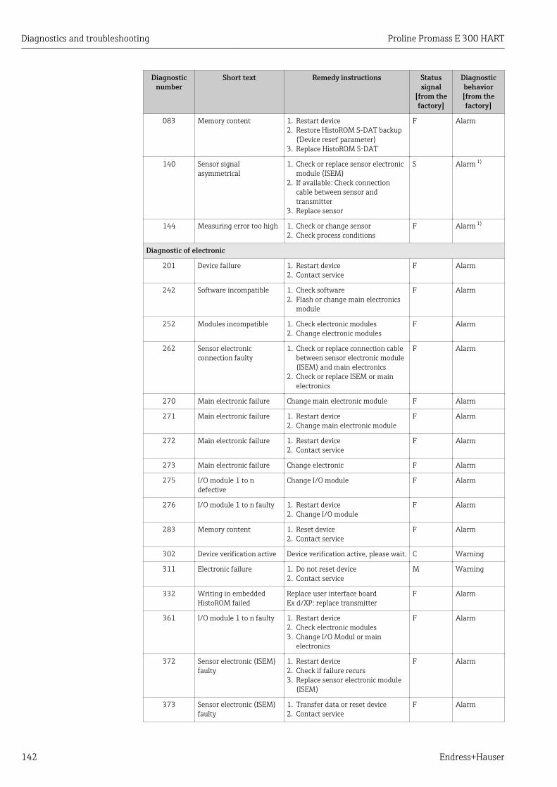
Diagnostics and troubleshooting Proline Promass E 300 HART
142 Endress+Hauser
Diagnosticnumber
Short text Remedy instructions Statussignal
[from thefactory]
Diagnosticbehavior[from thefactory]
083 Memory content 1. Restart device2. Restore HistoROM S-DAT backup
('Device reset' parameter)3. Replace HistoROM S-DAT
F Alarm
140 Sensor signalasymmetrical
1. Check or replace sensor electronicmodule (ISEM)
2. If available: Check connectioncable between sensor andtransmitter
3. Replace sensor
S Alarm 1)
144 Measuring error too high 1. Check or change sensor2. Check process conditions
F Alarm 1)
Diagnostic of electronic
201 Device failure 1. Restart device2. Contact service
F Alarm
242 Software incompatible 1. Check software2. Flash or change main electronics
module
F Alarm
252 Modules incompatible 1. Check electronic modules2. Change electronic modules
F Alarm
262 Sensor electronicconnection faulty
1. Check or replace connection cablebetween sensor electronic module(ISEM) and main electronics
2. Check or replace ISEM or mainelectronics
F Alarm
270 Main electronic failure Change main electronic module F Alarm
271 Main electronic failure 1. Restart device2. Change main electronic module
F Alarm
272 Main electronic failure 1. Restart device2. Contact service
F Alarm
273 Main electronic failure Change electronic F Alarm
275 I/O module 1 to ndefective
Change I/O module F Alarm
276 I/O module 1 to n faulty 1. Restart device2. Change I/O module
F Alarm
283 Memory content 1. Reset device2. Contact service
F Alarm
302 Device verification active Device verification active, please wait. C Warning
311 Electronic failure 1. Do not reset device2. Contact service
M Warning
332 Writing in embeddedHistoROM failed
Replace user interface boardEx d/XP: replace transmitter
F Alarm
361 I/O module 1 to n faulty 1. Restart device2. Check electronic modules3. Change I/O Modul or main
electronics
F Alarm
372 Sensor electronic (ISEM)faulty
1. Restart device2. Check if failure recurs3. Replace sensor electronic module
(ISEM)
F Alarm
373 Sensor electronic (ISEM)faulty
1. Transfer data or reset device2. Contact service
F Alarm
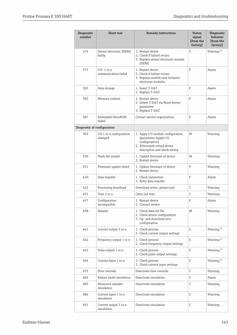
Proline Promass E 300 HART Diagnostics and troubleshooting
Endress+Hauser 143
Diagnosticnumber
Short text Remedy instructions Statussignal
[from thefactory]
Diagnosticbehavior[from thefactory]
374 Sensor electronic (ISEM)faulty
1. Restart device2. Check if failure recurs3. Replace sensor electronic module
(ISEM)
S Warning 1)
375 I/O- 1 to ncommunication failed
1. Restart device2. Check if failure recurs3. Replace module rack inclusive
electronic modules
F Alarm
382 Data storage 1. Insert T-DAT2. Replace T-DAT
F Alarm
383 Memory content 1. Restart device2. Delete T-DAT via 'Reset device'
parameter3. Replace T-DAT
F Alarm
387 Embedded HistoROMfailed
Contact service organization F Alarm
Diagnostic of configuration
303 I/O 1 to n configurationchanged
1. Apply I/O module configuration(parameter 'Apply I/Oconfiguration')
2. Afterwards reload devicedescription and check wiring
M Warning
330 Flash file invalid 1. Update firmware of device2. Restart device
M Warning
331 Firmware update failed 1. Update firmware of device2. Restart device
F Warning
410 Data transfer 1. Check connection2. Retry data transfer
F Alarm
412 Processing download Download active, please wait C Warning
431 Trim 1 to n Carry out trim C Warning
437 Configurationincompatible
1. Restart device2. Contact service
F Alarm
438 Dataset 1. Check data set file2. Check device configuration3. Up- and download new
configuration
M Warning
441 Current output 1 to n 1. Check process2. Check current output settings
S Warning 1)
442 Frequency output 1 to n 1. Check process2. Check frequency output settings
S Warning 1)
443 Pulse output 1 to n 1. Check process2. Check pulse output settings
S Warning 1)
444 Current input 1 to n 1. Check process2. Check current input settings
S Warning 1)
453 Flow override Deactivate flow override C Warning
484 Failure mode simulation Deactivate simulation C Alarm
485 Measured variablesimulation
Deactivate simulation C Warning
486 Current input 1 to nsimulation
Deactivate simulation C Warning
491 Current output 1 to nsimulation
Deactivate simulation C Warning
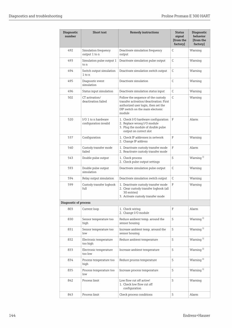
Diagnostics and troubleshooting Proline Promass E 300 HART
144 Endress+Hauser
Diagnosticnumber
Short text Remedy instructions Statussignal
[from thefactory]
Diagnosticbehavior[from thefactory]
492 Simulation frequencyoutput 1 to n
Deactivate simulation frequencyoutput
C Warning
493 Simulation pulse output 1to n
Deactivate simulation pulse output C Warning
494 Switch output simulation1 to n
Deactivate simulation switch output C Warning
495 Diagnostic eventsimulation
Deactivate simulation C Warning
496 Status input simulation Deactivate simulation status input C Warning
502 CT activation/deactivation failed
Follow the sequence of the custodytransfer activation/deactivation: Firstauthorized user login, then set theDIP switch on the main electonicmodule
C Warning
520 I/O 1 to n hardwareconfiguration invalid
1. Check I/O hardware configuration2. Replace wrong I/O module3. Plug the module of double pulse
output on correct slot
F Alarm
537 Configuration 1. Check IP addresses in network2. Change IP address
F Warning
540 Custody transfer modefailed
1. Deactivate custody transfer mode2. Reactivate custody transfer mode
F Alarm
543 Double pulse output 1. Check process2. Check pulse output settings
S Warning 1)
593 Double pulse outputsimulation
Deactivate simulation pulse output C Warning
594 Relay output simulation Deactivate simulation switch output C Warning
599 Custody transfer logbookfull
1. Deactivate custody transfer mode2. Clear custody transfer logbook (all
30 entries)3. Activate custody transfer mode
F Warning
Diagnostic of process
803 Current loop 1. Check wiring2. Change I/O module
F Alarm
830 Sensor temperature toohigh
Reduce ambient temp. around thesensor housing
S Warning 1)
831 Sensor temperature toolow
Increase ambient temp. around thesensor housing
S Warning 1)
832 Electronic temperaturetoo high
Reduce ambient temperature S Warning 1)
833 Electronic temperaturetoo low
Increase ambient temperature S Warning 1)
834 Process temperature toohigh
Reduce process temperature S Warning 1)
835 Process temperature toolow
Increase process temperature S Warning 1)
842 Process limit Low flow cut off active!1. Check low flow cut off
configuration
S Warning
843 Process limit Check process conditions S Alarm
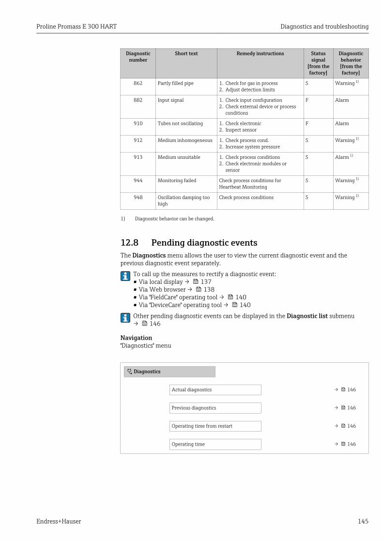
Proline Promass E 300 HART Diagnostics and troubleshooting
Endress+Hauser 145
Diagnosticnumber
Short text Remedy instructions Statussignal
[from thefactory]
Diagnosticbehavior[from thefactory]
862 Partly filled pipe 1. Check for gas in process2. Adjust detection limits
S Warning 1)
882 Input signal 1. Check input configuration2. Check external device or process
conditions
F Alarm
910 Tubes not oscillating 1. Check electronic2. Inspect sensor
F Alarm
912 Medium inhomogeneous 1. Check process cond.2. Increase system pressure
S Warning 1)
913 Medium unsuitable 1. Check process conditions2. Check electronic modules or
sensor
S Alarm 1)
944 Monitoring failed Check process conditions forHeartbeat Monitoring
S Warning 1)
948 Oscillation damping toohigh
Check process conditions S Warning 1)
1) Diagnostic behavior can be changed.
12.8 Pending diagnostic eventsThe Diagnostics menu allows the user to view the current diagnostic event and theprevious diagnostic event separately.
To call up the measures to rectify a diagnostic event:• Via local display → 137• Via Web browser → 138• Via "FieldCare" operating tool → 140• Via "DeviceCare" operating tool → 140
Other pending diagnostic events can be displayed in the Diagnostic list submenu→ 146
Navigation"Diagnostics" menu
Diagnostics
Actual diagnostics → 146
Previous diagnostics → 146
Operating time from restart → 146
Operating time → 146

Diagnostics and troubleshooting Proline Promass E 300 HART
146 Endress+Hauser
Parameter overview with brief description
Parameter Prerequisite Description User interface
Actual diagnostics A diagnostic event has occurred. Shows the current occured diagnosticevent along with its diagnosticinformation.
If two or more messages occursimultaneously, the message withthe highest priority is shown onthe display.
Symbol for diagnosticbehavior, diagnostic codeand short message.
Previous diagnostics Two diagnostic events have alreadyoccurred.
Shows the diagnostic event thatoccurred prior to the current diagnosticevent along with its diagnosticinformation.
Symbol for diagnosticbehavior, diagnostic codeand short message.
Operating time from restart – Shows the time the device has been inoperation since the last device restart.
Days (d), hours (h),minutes (m) and seconds(s)
Operating time – Indicates how long the device has beenin operation.
Days (d), hours (h),minutes (m) and seconds(s)
12.9 Diagnostic listUp to 5 currently pending diagnostic events can be displayed in the Diagnostic listsubmenu along with the associated diagnostic information. If more than 5 diagnosticevents are pending, the events with the highest priority are shown on the display.
Navigation pathDiagnostics → Diagnostic list
Diagnostics
/ ../Diagnose list
Diagnostics 3
Diagnostics 2
F273 Main electronic
A0014006-EN
33 Taking the example of the local display
To call up the measures to rectify a diagnostic event:• Via local display → 137• Via Web browser → 138• Via "FieldCare" operating tool → 140• Via "DeviceCare" operating tool → 140
12.10 Event logbook
12.10.1 Event historyA chronological overview of the event messages that have occurred is provided in theEvents list submenu.
Navigation pathDiagnostics menu → Event logbook submenu → Event list

Proline Promass E 300 HART Diagnostics and troubleshooting
Endress+Hauser 147
FI1091 Config. change
I1157 Mem.err. ev.list
F311 Electr. failure
/ ../Eventlist
0d01h19m10s
A0014008-EN
34 Taking the example of the local display
• Max. 20 event messages can be displayed in chronological order.• If the Extended HistoROM application package (order option) is enabled in the device,
the event list can contain up to 100 entries .
The event history includes entries for:• Diagnostic events → 141• Information events → 147
In addition to the operation time of its occurrence, each event is also assigned a symbolthat indicates whether the event has occurred or is ended:• Diagnostic event
– : Occurrence of the event– : End of the event
• Information event: Occurrence of the event
To call up the measures to rectify a diagnostic event:• Via local display → 137• Via Web browser → 138• Via "FieldCare" operating tool → 140• Via "DeviceCare" operating tool → 140
For filtering the displayed event messages → 147
12.10.2 Filtering the event logbookUsing the Filter options parameter you can define which category of event message isdisplayed in the Events list submenu.
Navigation pathDiagnostics → Event logbook → Filter options
Filter categories• All• Failure (F)• Function check (C)• Out of specification (S)• Maintenance required (M)• Information (I)
12.10.3 Overview of information eventsUnlike a diagnostic event, an information event is displayed in the event logbook only andnot in the diagnostic list.
Info number Info name
I1000 --------(Device ok)
I1079 Sensor changed
I1089 Power on
I1090 Configuration reset
I1091 Configuration changed

Diagnostics and troubleshooting Proline Promass E 300 HART
148 Endress+Hauser
Info number Info name
I1092 Embedded HistoROM deleted
I1111 Density adjust failure
I1137 Electronic changed
I1151 History reset
I1155 Reset electronic temperature
I1156 Memory error trend
I1157 Memory error event list
I1184 Display connected
I1209 Density adjustment ok
I1221 Zero point adjust failure
I1222 Zero point adjustment ok
I1256 Display: access status changed
I1264 Safety sequence aborted
I1278 I/O module reset detected
I1335 Firmware changed
I1361 Web server login failed
I1397 Fieldbus: access status changed
I1398 CDI: access status changed
I1444 Device verification passed
I1445 Device verification failed
I1447 Record application reference data
I1448 Application reference data recorded
I1449 Recording application ref. data failed
I1450 Monitoring off
I1451 Monitoring on
I1457 Measured error verification failed
I1459 I/O module verification failed
I1460 HBSI verification failed
I1461 Sensor verification failed
I1462 Sensor electronic module verific. failed
I1512 Download started
I1513 Download finished
I1514 Upload started
I1515 Upload finished
I1517 Custody transfer active
I1518 Custody transfer inactive
I1554 Safety sequence started
I1555 Safety sequence confirmed
I1556 Safety mode off
I1618 I/O module replaced
I1619 I/O module replaced
I1621 I/O module replaced
I1622 Calibration changed

Proline Promass E 300 HART Diagnostics and troubleshooting
Endress+Hauser 149
Info number Info name
I1624 Reset all totalizers
I1625 Write protection activated
I1626 Write protection deactivated
I1627 Web server login successful
I1628 Display login successful
I1629 CDI login successful
I1631 Web server access changed
I1632 Display login failed
I1633 CDI login failed
I1634 Parameter factory reset
I1635 Parameter delivery reset
I1639 Max. switch cycles number reached
I1643 Custody transfer logbook cleared
I1649 Hardware write protection activated
I1650 Hardware write protection deactivated
I1651 Custody transfer parameter changed
I1712 New flash file received
I1725 Sensor electronic module (ISEM) changed
I1726 Configuration backup failed
12.11 Resetting the measuring deviceUsing theDevice reset parameter (→ 114) it is possible to reset the entire deviceconfiguration or some of the configuration to a defined state.
12.11.1 Function scope of the "Device reset" parameter
Options Description
Cancel No action is executed and the user exits the parameter.
To delivery settings Every parameter for which a customer-specific default setting was ordered is resetto this customer-specific value. All other parameters are reset to the factorysetting.
Restart device The restart resets every parameter whose data are in the volatile memory (RAM)to the factory setting (e.g. measured value data). The device configuration remainsunchanged.
Restore S-DAT backup Restore the data that are saved on the S-DAT. The data record is restored from theelectronics memory to the S-DAT.
12.12 Device informationThe Device information submenu contains all parameters that display differentinformation for device identification.

Diagnostics and troubleshooting Proline Promass E 300 HART
150 Endress+Hauser
Navigation"Diagnostics" menu → Device information
‣ Device information
Device tag → 150
Serial number → 150
Firmware version → 150
Device name → 150
Order code → 150
Extended order code 1 → 151
Extended order code 2 → 151
Extended order code 3 → 151
ENP version → 151
Device revision → 151
Device ID → 151
Device type → 151
Manufacturer ID → 151
Parameter overview with brief description
Parameter Description User interface Factory setting
Device tag Shows name of measuring point. Max. 32 characters, such asletters, numbers or specialcharacters (e.g. @, %, /).
Promass300/500
Serial number Shows the serial number of the measuringdevice.
A maximum of 11-digitcharacter string comprisingletters and numbers.
–
Firmware version Shows the device firmware version installed. Character string in the formatxx.yy.zz
–
Device name Shows the name of the transmitter.
The name can be found on thenameplate of the transmitter.
Promass300/500 –
Order code Shows the device order code.
The order code can be found on thenameplate of the sensor andtransmitter in the "Order code" field.
Character string composed ofletters, numbers and certainpunctuation marks (e.g. /).
–

Proline Promass E 300 HART Diagnostics and troubleshooting
Endress+Hauser 151
Parameter Description User interface Factory setting
Extended order code 1 Shows the 1st part of the extended ordercode.
The extended order code can also befound on the nameplate of the sensorand transmitter in the "Ext. ord. cd."field.
Character string –
Extended order code 2 Shows the 2nd part of the extended ordercode.
The extended order code can also befound on the nameplate of the sensorand transmitter in the "Ext. ord. cd."field.
Character string –
Extended order code 3 Shows the 3rd part of the extended ordercode.
The extended order code can also befound on the nameplate of the sensorand transmitter in the "Ext. ord. cd."field.
Character string –
ENP version Shows the version of the electronicnameplate (ENP).
Character string 2.02.00
Device revision Shows the device revision with which thedevice is registered with the HARTCommunication Foundation.
2-digit hexadecimal number 1
Device ID Shows the device ID for identifying thedevice in a HART network.
6-digit hexadecimal number –
Device type Shows the device type with which themeasuring device is registered with theHART Communication Foundation.
2-digit hexadecimal number 0x3B (for Promass 300/500)
Manufacturer ID Shows the manufacturer ID device isregistered with the HART CommunicationFoundation.
2-digit hexadecimal number 0x11 (for Endress+Hauser)
12.13 Firmware history
Releasedate
Firmwareversion
Order codefor
"Firmwareversion"
Firmwarechanges
Documentationtype
Documentation
08.2016 01.00.zz Option 78 Original firmware OperatingInstructions
BA01484D/06/EN/01.16
It is possible to flash the firmware to the current version or the previous version usingthe service interface.
For the compatibility of the firmware version with the previous version, the installeddevice description files and operating tools, observe the information about the devicein the "Manufacturer's information" document.
The manufacturer's information is available:• In the Download Area of the Endress+Hauser web site: www.endress.com →
Downloads• Specify the following details:
– Product root, e.g. 8E3B– Text search: Manufacturer's information– Media type: Documentation – Technical Documentation

Maintenance Proline Promass E 300 HART
152 Endress+Hauser
13 Maintenance
13.1 Maintenance tasksNo special maintenance work is required.
13.1.1 Exterior cleaningWhen cleaning the exterior of measuring devices, always use cleaning agents that do notattack the surface of the housing or the seals.
13.1.2 Interior cleaningObserve the following points for CIP and SIP cleaning:• Use only cleaning agents to which the process-wetted materials are adequately resistant.• Observe the maximum permitted medium temperature for the measuring device
→ 173.
13.2 Measuring and test equipmentEndress+Hauser offers a wide variety of measuring and test equipment, such as W@M ordevice tests.
Your Endress+Hauser Sales Center can provide detailed information on the services.
List of some of the measuring and testing equipment: → 155
13.3 Endress+Hauser servicesEndress+Hauser offers a wide variety of services for maintenance such as recalibration,maintenance service or device tests.
Your Endress+Hauser Sales Center can provide detailed information on the services.

Proline Promass E 300 HART Repairs
Endress+Hauser 153
14 Repairs
14.1 General notes
14.1.1 Repair and conversion conceptThe Endress+Hauser repair and conversion concept provides for the following:• The measuring devices have a modular design.• Spare parts are grouped into logical kits with the associated Installation Instructions.• Repairs are carried out by Endress+Hauser Service or by appropriately trained customers.• Certified devices can only be converted to other certified devices by Endress+Hauser
Service or at the factory.
14.1.2 Notes for repair and conversionFor repair and modification of a measuring device, observe the following notes:‣ Use only original Endress+Hauser spare parts.‣ Carry out the repair according to the Installation Instructions.‣ Observe the applicable standards, federal/national regulations, Ex documentation (XA)
and certificates.‣ Document every repair and each conversion and enter them into the W@M life cycle
management database.
14.2 Spare partsW@M Device Viewer (www.endress.com/deviceviewer):All the spare parts for the measuring device, along with the order code, are listed here andcan be ordered. If available, users can also download the associated InstallationInstructions.
Measuring device serial number:• Is located on the nameplate of the device.• Can be read out via the Serial number parameter (→ 150) in the Device
information submenu.
14.3 Endress+Hauser servicesEndress+Hauser offers a wide range of services.
Your Endress+Hauser Sales Center can provide detailed information on the services.
14.4 ReturnThe measuring device must be returned if it is need of repair or a factory calibration, or ifthe wrong measuring device has been delivered or ordered. Legal specifications requireEndress+Hauser, as an ISO-certified company, to follow certain procedures when handlingproducts that are in contact with the medium.
To ensure safe, swift and professional device returns, please refer to the procedure andconditions for returning devices provided on the Endress+Hauser website athttp://www.endress.com/support/return-material

Repairs Proline Promass E 300 HART
154 Endress+Hauser
14.5 Disposal
14.5.1 Removing the measuring device1. Switch off the device.
LWARNINGDanger to persons from process conditions.‣ Beware of hazardous process conditions such as pressure in the measuring device, high
temperatures or aggressive fluids.
2. Carry out the mounting and connection steps from the "Mounting the measuringdevice" and "Connecting the measuring device" sections in reverse order. Observe thesafety instructions.
14.5.2 Disposing of the measuring deviceLWARNING
Danger to personnel and environment from fluids that are hazardous to health.‣ Ensure that the measuring device and all cavities are free of fluid residues that are
hazardous to health or the environment, e.g. substances that have permeated intocrevices or diffused through plastic.
Observe the following notes during disposal:‣ Observe valid federal/national regulations.‣ Ensure proper separation and reuse of the device components.

Proline Promass E 300 HART Accessories
Endress+Hauser 155
15 AccessoriesVarious accessories, which can be ordered with the device or subsequently from Endress+Hauser, are available for the device. Detailed information on the order code in question isavailable from your local Endress+Hauser sales center or on the product page of theEndress+Hauser website: www.endress.com.
15.1 Device-specific accessories
15.1.1 For the transmitter
Accessories Description
Promass 300 transmitter Transmitter for replacement or storage. Use the order code to define the followingspecifications:• Approvals• Output• Input• Display / operation• Housing• Software
For details, see Installation Instructions EA01150
Remote display andoperating moduleDKX001
The remote display and operating module DKX001 is available as an optional extra:Order code for "Display; operation", option O "Separate backlit, 4-line display;10 m (30 ft) Cable; touch control"
The remote display and operating module DKX001 can also be ordered separatelyand subsequently as an accessory without a measuring device .
Further information on display and operating module DKX001→ 178.
For details, see Special Documentation SD01763D
WLAN antennaWide range
External WLAN antenna for a range of up to 50 m (165 ft).
Further information on the WLAN interface → 63.
Protective cover Is used to protect the measuring device from the effects of the weather: e.g.rainwater, excess heating from direct sunlight.
For details, see Installation Instructions EA01160
15.1.2 For the sensor
Accessories Description
Heating jacket Is used to stabilize the temperature of the fluids in the sensor.Water, water vapor and other non-corrosive liquids are permitted for use as fluids.If using oil as a heating medium, please consult with Endress+Hauser.Heating jackets cannot be used with sensors fitted with a rupture disk.
15.2 Communication-specific accessories
Accessories Description
Commubox FXA195HART
For intrinsically safe HART communication with FieldCare via the USB interface.
For details, see "Technical Information" TI00404F

Accessories Proline Promass E 300 HART
156 Endress+Hauser
HART Loop ConverterHMX50
Is used to evaluate and convert dynamic HART process variables to analog currentsignals or limit values.
For details, see "Technical Information" TI00429F and Operating InstructionsBA00371F
Fieldgate FXA320 Gateway for the remote monitoring of connected 4 to 20 mA measuring devices viaa Web browser.
For details, see "Technical Information" TI00025S and Operating InstructionsBA00053S
Fieldgate FXA520 Gateway for the remote diagnostics and remote configuration of connected HARTmeasuring devices via a Web browser.
For details, see "Technical Information" TI00025S and Operating InstructionsBA00051S
Field Xpert SFX350 Field Xpert SFX350 is a mobile computer for commissioning and maintenance. Itenables efficient device configuration and diagnostics for HART and FOUNDATIONFieldbus devices in the non-Ex area.
For details, see Operating Instructions BA01202S
Field Xpert SFX370 Field Xpert SFX370 is a mobile computer for commissioning and maintenance. Itenables efficient device configuration and diagnostics for HART and FOUNDATIONFieldbus devices in the non-Ex area and the Ex area.
For details, see Operating Instructions BA01202S
15.3 Service-specific accessories
Accessories Description
Applicator Software for selecting and sizing Endress+Hauser measuring devices:• Choice of measuring devices for industrial requirements• Calculation of all the necessary data for identifying the optimum flowmeter: e.g.
nominal diameter, pressure loss, flow velocity and accuracy.• Graphic illustration of the calculation results• Determination of the partial order code, administration, documentation and
access to all project-related data and parameters over the entire life cycle of aproject.
Applicator is available:• Via the Internet: https://wapps.endress.com/applicator• As a downloadable DVD for local PC installation.
W@M W@M Life Cycle ManagementImproved productivity with information at your fingertips. Data relevant to a plantand its components is generated from the first stages of planning and during theasset’s complete life cycle.W@M Life Cycle Management is an open and flexible information platform withonline and on-site tools. Instant access for your staff to current, in-depth datashortens your plant’s engineering time, speeds up procurement processes andincreases plant uptime.Combined with the right services, W@M Life Cycle Management boostsproductivity in every phase. For more information, visitwww.endress.com/lifecyclemanagement
FieldCare FDT-based plant asset management tool from Endress+Hauser.It can configure all smart field units in your system and helps you manage them. Byusing the status information, it is also a simple but effective way of checking theirstatus and condition.
For details, see Operating Instructions BA00027S and BA00059S
DeviceCare Tool for connecting and configuring Endress+Hauser field devices.
For details, see Innovation brochure IN01047S

Proline Promass E 300 HART Accessories
Endress+Hauser 157
15.4 System components
Accessories Description
Memograph M graphicdisplay recorder
The Memograph M graphic display recorder provides information on all relevantmeasured variables. Measured values are recorded correctly, limit values aremonitored and measuring points analyzed. The data are stored in the 256 MBinternal memory and also on a SD card or USB stick.
For details, see "Technical Information" TI00133R and Operating InstructionsBA00247R
Cerabar M The pressure transmitter for measuring the absolute and gauge pressure of gases,steam and liquids. It can be used to read in the operating pressure value.
For details, see "Technical Information" TI00426P, TI00436P and OperatingInstructions BA00200P, BA00382P
Cerabar S The pressure transmitter for measuring the absolute and gauge pressure of gases,steam and liquids. It can be used to read in the operating pressure value.
For details, see "Technical Information" TI00383P and Operating InstructionsBA00271P
iTEMP The temperature transmitters can be used in all applications and are suitable forthe measurement of gases, steam and liquids. They can be used to read in the fluidtemperature.
For details, see "Fields of Activity", FA00006T

Technical data Proline Promass E 300 HART
158 Endress+Hauser
16 Technical data
16.1 ApplicationThe measuring device is suitable for flow measurement of liquids and gases only.
Depending on the version ordered, the measuring device can also measure potentiallyexplosive, flammable, poisonous and oxidizing media.
To ensure that the device remains in proper operating condition for its service life, use themeasuring device only for media against which the process-wetted materials aresufficiently resistant.
16.2 Function and system design
Measuring principle Mass flow measurement based on the Coriolis measuring principle
Measuring system The device consists of a transmitter and a sensor.
The device is available as a compact version:The transmitter and sensor form a mechanical unit.
For information on the structure of the device → 14

Proline Promass E 300 HART Technical data
Endress+Hauser 159
16.3 Input
Measured variable Direct measured variables• Mass flow• Density• Temperature
Calculated measured variables• Volume flow• Corrected volume flow• Reference density
Measuring range Measuring ranges for liquids
DN Measuring range full scale values min(F) to max(F)
[mm] [in] [kg/h] [lb/min]
8 ³⁄₈ 0 to 2 000 0 to 73.50
15 ½ 0 to 6 500 0 to 238.9
25 1 0 to 18 000 0 to 661.5
40 1½ 0 to 45 000 0 to 1 654
50 2 0 to 70 000 0 to 2 573
80 3 0 to 180 000 0 to 6 615
Measuring ranges for gases The full scale values depend on the density of the gas and can be calculated with theformula below:max(G) = max(F) · ρG : x
max(G) Maximum full scale value for gas [kg/h]
max(F) Maximum full scale value for liquid [kg/h]
max(G) < max(F) max(G) can never be greater than max(F)
ρG Gas density in [kg/m³] at operating conditions
x Constant dependent on nominal diameter
DN x
[mm] [in] [kg/m3]
8 ³⁄₈ 85
15 ½ 110
25 1 125
40 1½ 125
50 2 125
80 3 155

Technical data Proline Promass E 300 HART
160 Endress+Hauser
Calculation example for gas• Sensor: Promass E, DN 50• Gas: Air with a density of 60.3 kg/m³ (at 20 °C and 50 bar)• Measuring range (liquid): 70 000 kg/h• x = 125 kg/m³ (for Promass E, DN 50)
Maximum possible full scale value: max(G) = max(F) · ρG : x = 70 000 kg/h · 60.3 kg/m³ : 125 kg/m³ = 33 800 kg/h
Recommended measuring range"Flow limit" section → 174
Operable flow range Over 1000 : 1.
Flow rates above the preset full scale value do not override the electronics unit, with theresult that the totalizer values are registered correctly.
Input signal External measured valuesTo increase the accuracy of certain measured variables or to calculate the corrected volumeflow for gases, the automation system can continuously write different measured values tothe measuring device:• Operating pressure to increase accuracy (Endress+Hauser recommends the use of a
pressure measuring device for absolute pressure, e.g. Cerabar M or Cerabar S)• Fluid temperature to increase accuracy (e.g. iTEMP)• Reference density for calculating the corrected volume flow for gases
Various pressure transmitters and temperature measuring devices can be orderedfrom Endress+Hauser: see "Accessories" section → 157
It is recommended to read in external measured values to calculate the following measuredvariables for gases:• Mass flow• Corrected volume flow
HART protocol
The measured values are written from the automation system to the measuring device viathe HART protocol. The pressure transmitter must support the following protocol-specificfunctions:• HART protocol• Burst mode
Current input
The measured values are written from the automation system to the measuring device viathe current input → 160.
Current input 0/4 to 20 mA
Current input 0/4 to 20 mA (active/passive)
Current span • 4 to 20 mA (active)• 0/4 to 20 mA (passive)
Resolution 1 µA
Voltage drop Typically: 0.6 to 2 V for 3.6 to 22 mA (passive)
Maximum input voltage ≤ 30 V (passive)
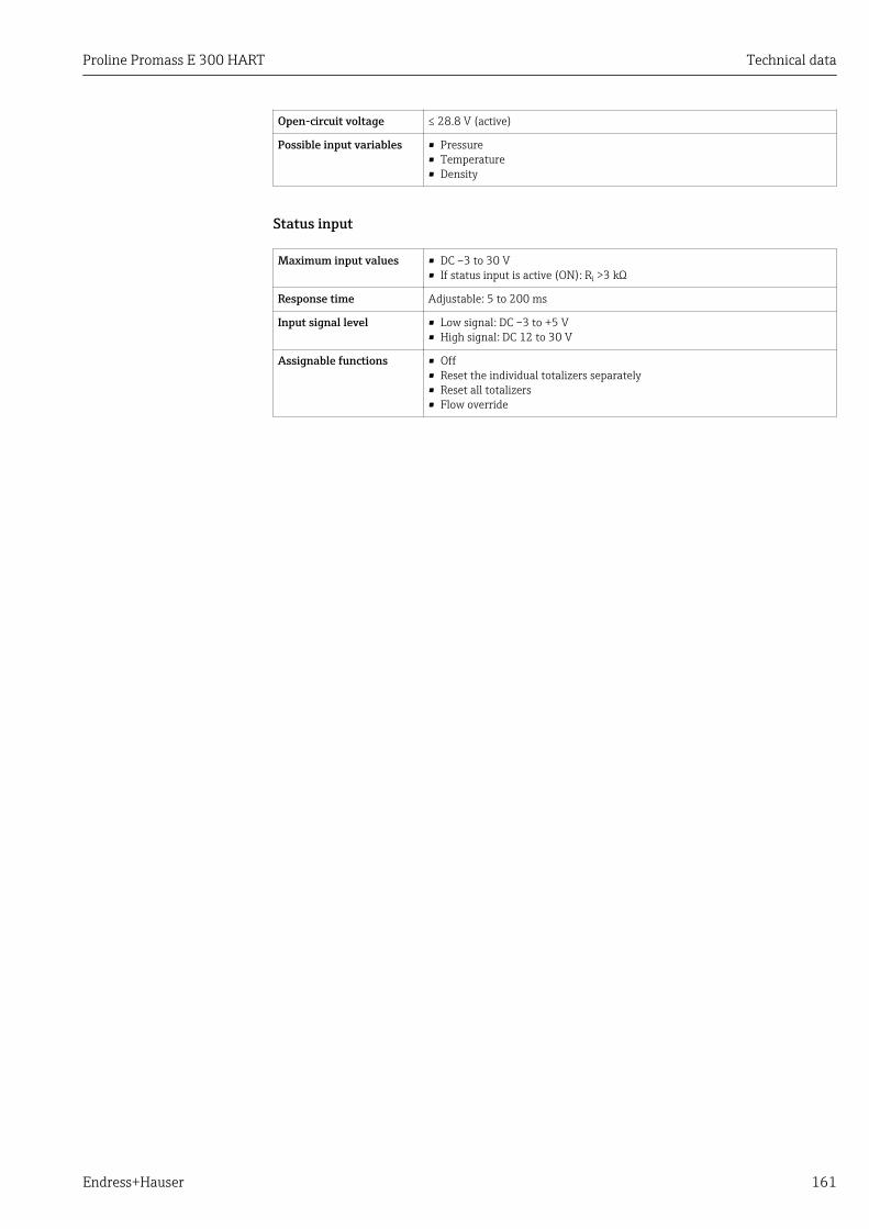
Proline Promass E 300 HART Technical data
Endress+Hauser 161
Open-circuit voltage ≤ 28.8 V (active)
Possible input variables • Pressure• Temperature• Density
Status input
Maximum input values • DC –3 to 30 V• If status input is active (ON): Ri >3 kΩ
Response time Adjustable: 5 to 200 ms
Input signal level • Low signal: DC –3 to +5 V• High signal: DC 12 to 30 V
Assignable functions • Off• Reset the individual totalizers separately• Reset all totalizers• Flow override
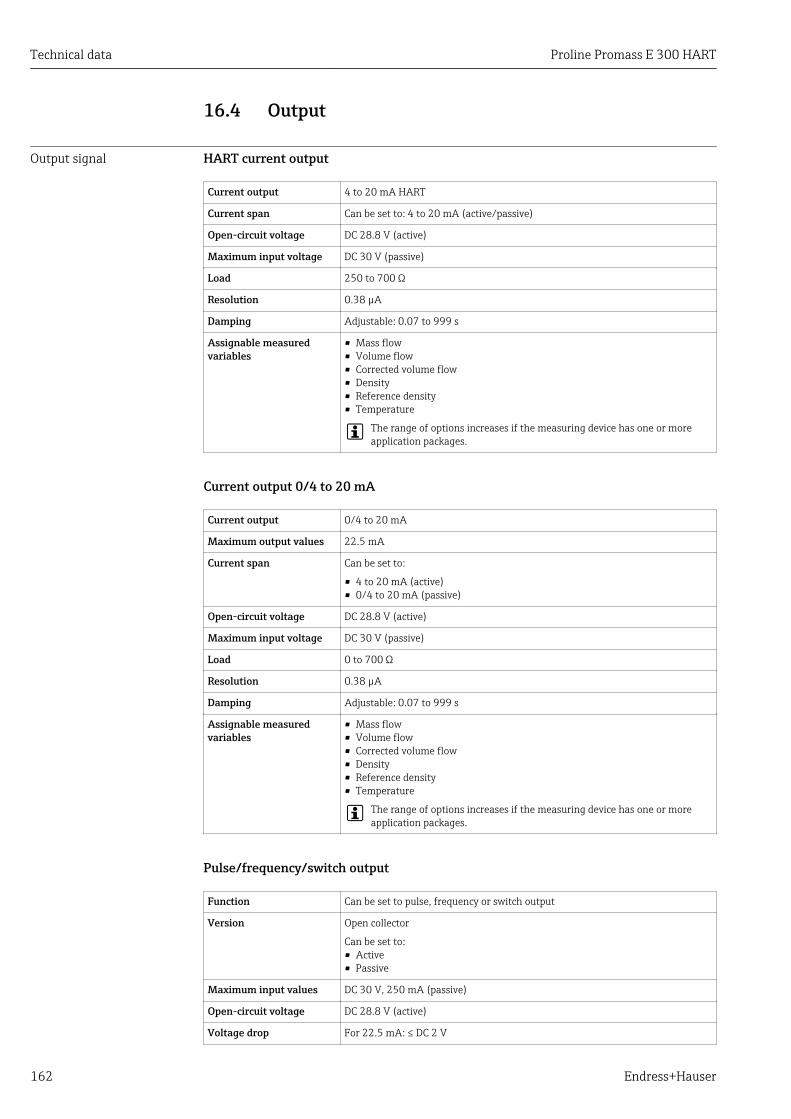
Technical data Proline Promass E 300 HART
162 Endress+Hauser
16.4 Output
Output signal HART current output
Current output 4 to 20 mA HART
Current span Can be set to: 4 to 20 mA (active/passive)
Open-circuit voltage DC 28.8 V (active)
Maximum input voltage DC 30 V (passive)
Load 250 to 700 Ω
Resolution 0.38 µA
Damping Adjustable: 0.07 to 999 s
Assignable measuredvariables
• Mass flow• Volume flow• Corrected volume flow• Density• Reference density• Temperature
The range of options increases if the measuring device has one or moreapplication packages.
Current output 0/4 to 20 mA
Current output 0/4 to 20 mA
Maximum output values 22.5 mA
Current span Can be set to:
• 4 to 20 mA (active)• 0/4 to 20 mA (passive)
Open-circuit voltage DC 28.8 V (active)
Maximum input voltage DC 30 V (passive)
Load 0 to 700 Ω
Resolution 0.38 µA
Damping Adjustable: 0.07 to 999 s
Assignable measuredvariables
• Mass flow• Volume flow• Corrected volume flow• Density• Reference density• Temperature
The range of options increases if the measuring device has one or moreapplication packages.
Pulse/frequency/switch output
Function Can be set to pulse, frequency or switch output
Version Open collector
Can be set to:• Active• Passive
Maximum input values DC 30 V, 250 mA (passive)
Open-circuit voltage DC 28.8 V (active)
Voltage drop For 22.5 mA: ≤ DC 2 V
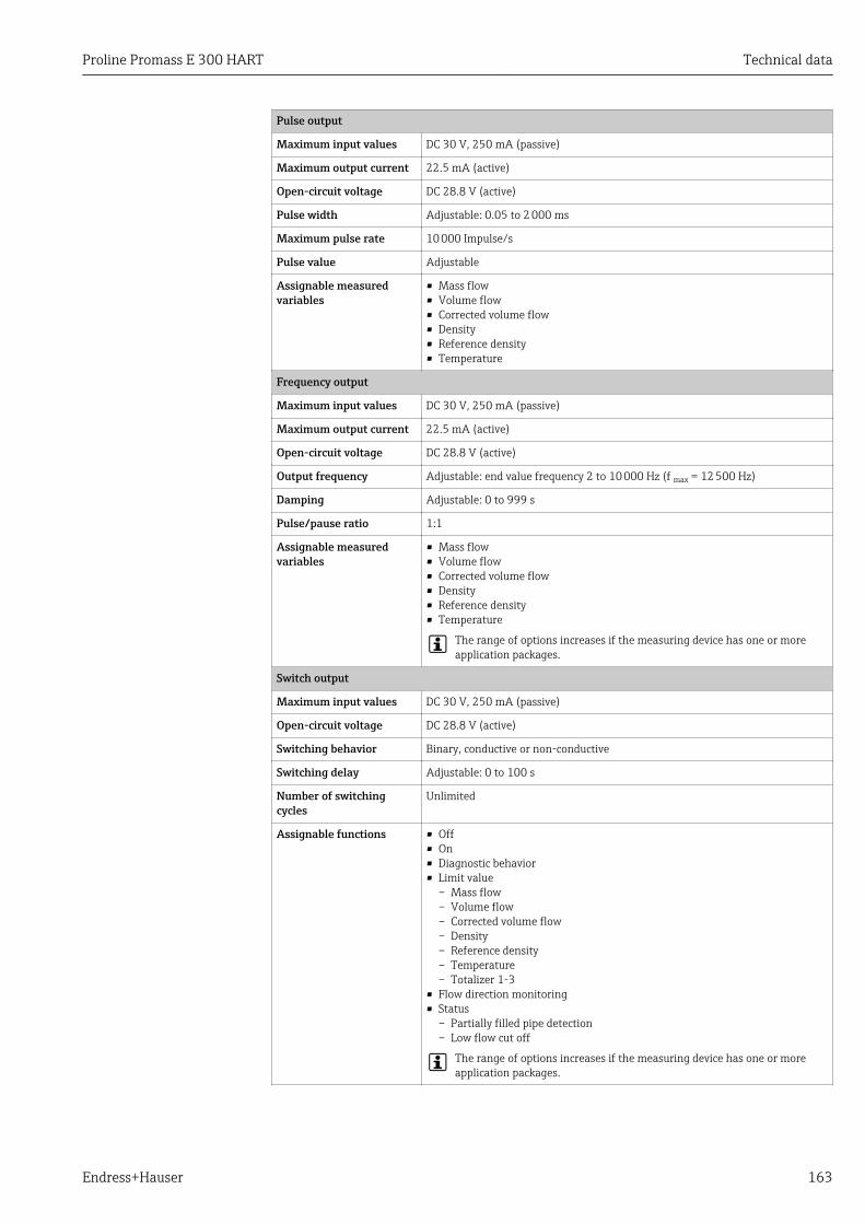
Proline Promass E 300 HART Technical data
Endress+Hauser 163
Pulse output
Maximum input values DC 30 V, 250 mA (passive)
Maximum output current 22.5 mA (active)
Open-circuit voltage DC 28.8 V (active)
Pulse width Adjustable: 0.05 to 2 000 ms
Maximum pulse rate 10 000 Impulse/s
Pulse value Adjustable
Assignable measuredvariables
• Mass flow• Volume flow• Corrected volume flow• Density• Reference density• Temperature
Frequency output
Maximum input values DC 30 V, 250 mA (passive)
Maximum output current 22.5 mA (active)
Open-circuit voltage DC 28.8 V (active)
Output frequency Adjustable: end value frequency 2 to 10 000 Hz (f max = 12 500 Hz)
Damping Adjustable: 0 to 999 s
Pulse/pause ratio 1:1
Assignable measuredvariables
• Mass flow• Volume flow• Corrected volume flow• Density• Reference density• Temperature
The range of options increases if the measuring device has one or moreapplication packages.
Switch output
Maximum input values DC 30 V, 250 mA (passive)
Open-circuit voltage DC 28.8 V (active)
Switching behavior Binary, conductive or non-conductive
Switching delay Adjustable: 0 to 100 s
Number of switchingcycles
Unlimited
Assignable functions • Off• On• Diagnostic behavior• Limit value
– Mass flow– Volume flow– Corrected volume flow– Density– Reference density– Temperature– Totalizer 1-3
• Flow direction monitoring• Status
– Partially filled pipe detection– Low flow cut off
The range of options increases if the measuring device has one or moreapplication packages.
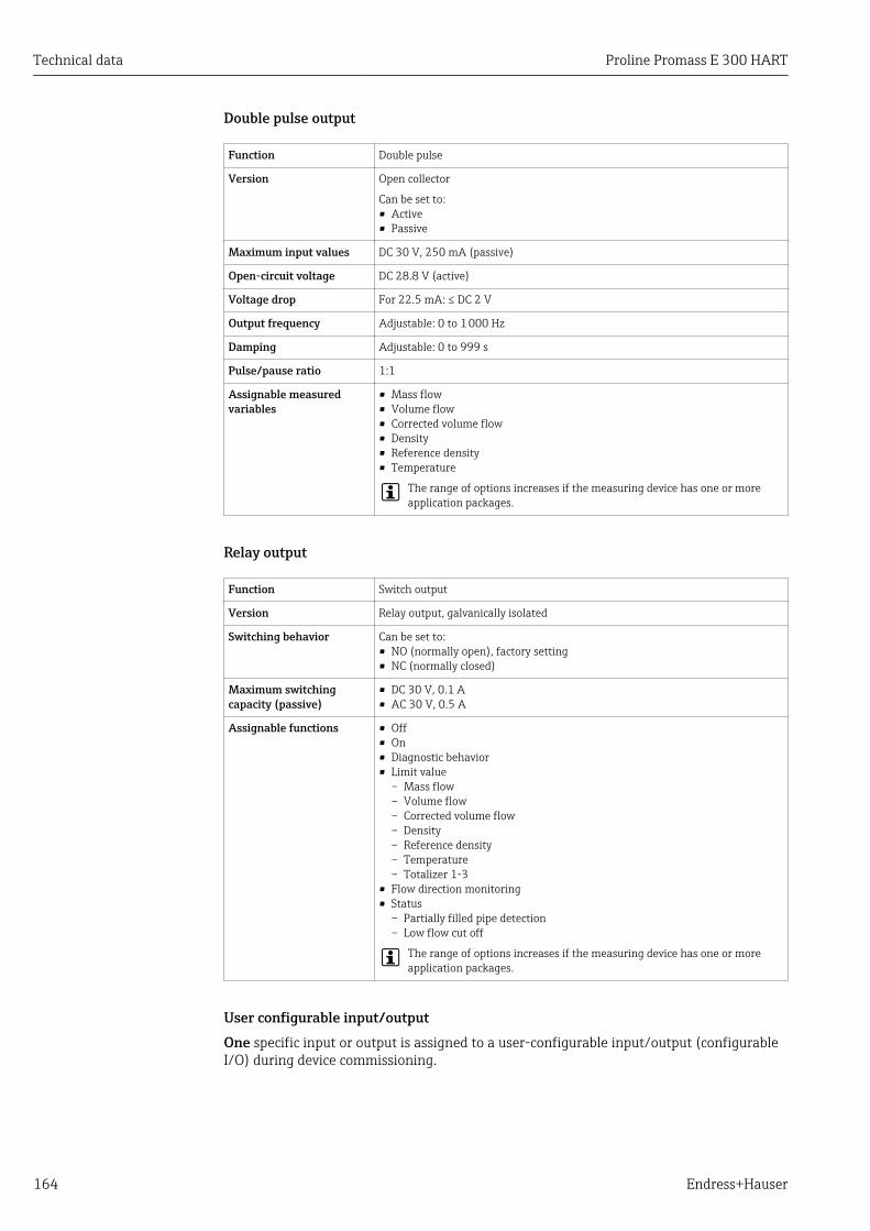
Technical data Proline Promass E 300 HART
164 Endress+Hauser
Double pulse output
Function Double pulse
Version Open collector
Can be set to:• Active• Passive
Maximum input values DC 30 V, 250 mA (passive)
Open-circuit voltage DC 28.8 V (active)
Voltage drop For 22.5 mA: ≤ DC 2 V
Output frequency Adjustable: 0 to 1 000 Hz
Damping Adjustable: 0 to 999 s
Pulse/pause ratio 1:1
Assignable measuredvariables
• Mass flow• Volume flow• Corrected volume flow• Density• Reference density• Temperature
The range of options increases if the measuring device has one or moreapplication packages.
Relay output
Function Switch output
Version Relay output, galvanically isolated
Switching behavior Can be set to:• NO (normally open), factory setting• NC (normally closed)
Maximum switchingcapacity (passive)
• DC 30 V, 0.1 A• AC 30 V, 0.5 A
Assignable functions • Off• On• Diagnostic behavior• Limit value
– Mass flow– Volume flow– Corrected volume flow– Density– Reference density– Temperature– Totalizer 1-3
• Flow direction monitoring• Status
– Partially filled pipe detection– Low flow cut off
The range of options increases if the measuring device has one or moreapplication packages.
User configurable input/outputOne specific input or output is assigned to a user-configurable input/output (configurableI/O) during device commissioning.
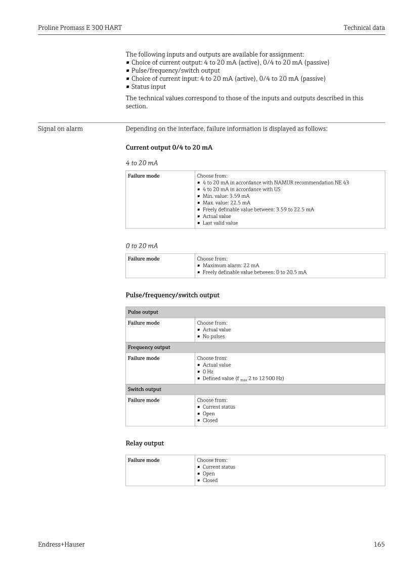
Proline Promass E 300 HART Technical data
Endress+Hauser 165
The following inputs and outputs are available for assignment:• Choice of current output: 4 to 20 mA (active), 0/4 to 20 mA (passive)• Pulse/frequency/switch output• Choice of current input: 4 to 20 mA (active), 0/4 to 20 mA (passive)• Status input
The technical values correspond to those of the inputs and outputs described in thissection.
Signal on alarm Depending on the interface, failure information is displayed as follows:
Current output 0/4 to 20 mA
4 to 20 mA
Failure mode Choose from:• 4 to 20 mA in accordance with NAMUR recommendation NE 43• 4 to 20 mA in accordance with US• Min. value: 3.59 mA• Max. value: 22.5 mA• Freely definable value between: 3.59 to 22.5 mA• Actual value• Last valid value
0 to 20 mA
Failure mode Choose from:• Maximum alarm: 22 mA• Freely definable value between: 0 to 20.5 mA
Pulse/frequency/switch output
Pulse output
Failure mode Choose from:• Actual value• No pulses
Frequency output
Failure mode Choose from:• Actual value• 0 Hz• Defined value (f max 2 to 12 500 Hz)
Switch output
Failure mode Choose from:• Current status• Open• Closed
Relay output
Failure mode Choose from:• Current status• Open• Closed
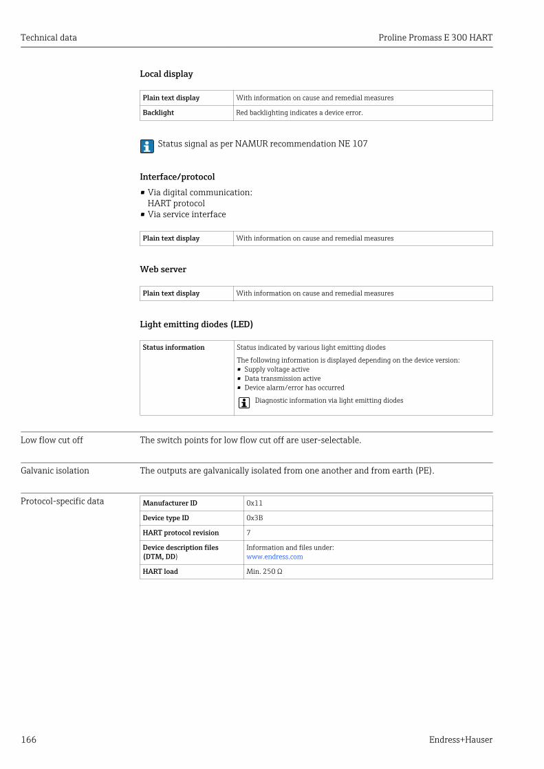
Technical data Proline Promass E 300 HART
166 Endress+Hauser
Local display
Plain text display With information on cause and remedial measures
Backlight Red backlighting indicates a device error.
Status signal as per NAMUR recommendation NE 107
Interface/protocol• Via digital communication:
HART protocol• Via service interface
Plain text display With information on cause and remedial measures
Web server
Plain text display With information on cause and remedial measures
Light emitting diodes (LED)
Status information Status indicated by various light emitting diodes
The following information is displayed depending on the device version:• Supply voltage active• Data transmission active• Device alarm/error has occurred
Diagnostic information via light emitting diodes
Low flow cut off The switch points for low flow cut off are user-selectable.
Galvanic isolation The outputs are galvanically isolated from one another and from earth (PE).
Protocol-specific data Manufacturer ID 0x11
Device type ID 0x3B
HART protocol revision 7
Device description files(DTM, DD)
Information and files under:www.endress.com
HART load Min. 250 Ω
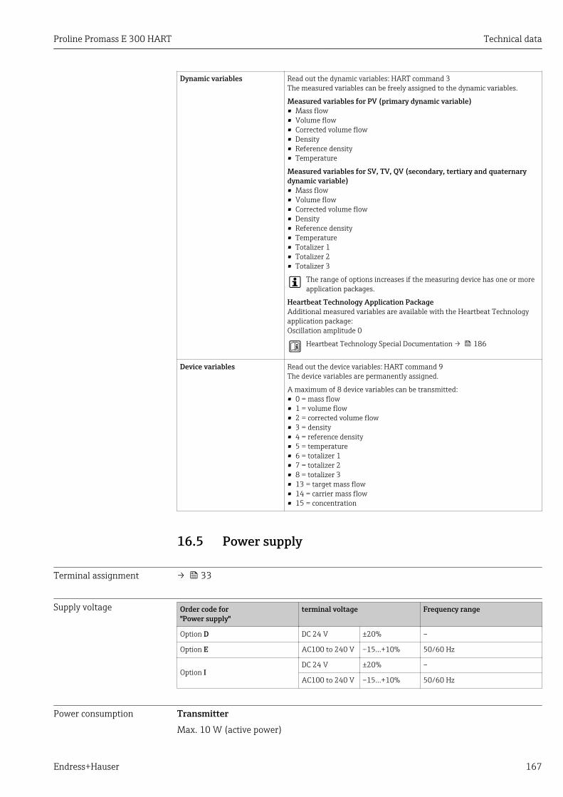
Proline Promass E 300 HART Technical data
Endress+Hauser 167
Dynamic variables Read out the dynamic variables: HART command 3The measured variables can be freely assigned to the dynamic variables.
Measured variables for PV (primary dynamic variable)• Mass flow• Volume flow• Corrected volume flow• Density• Reference density• Temperature
Measured variables for SV, TV, QV (secondary, tertiary and quaternarydynamic variable)• Mass flow• Volume flow• Corrected volume flow• Density• Reference density• Temperature• Totalizer 1• Totalizer 2• Totalizer 3
The range of options increases if the measuring device has one or moreapplication packages.
Heartbeat Technology Application PackageAdditional measured variables are available with the Heartbeat Technologyapplication package:Oscillation amplitude 0
Heartbeat Technology Special Documentation → 186
Device variables Read out the device variables: HART command 9The device variables are permanently assigned.
A maximum of 8 device variables can be transmitted:• 0 = mass flow• 1 = volume flow• 2 = corrected volume flow• 3 = density• 4 = reference density• 5 = temperature• 6 = totalizer 1• 7 = totalizer 2• 8 = totalizer 3• 13 = target mass flow• 14 = carrier mass flow• 15 = concentration
16.5 Power supply
Terminal assignment → 33
Supply voltage Order code for"Power supply"
terminal voltage Frequency range
Option D DC 24 V ±20% –
Option E AC100 to 240 V –15…+10% 50/60 Hz
Option IDC 24 V ±20% –
AC100 to 240 V –15…+10% 50/60 Hz
Power consumption TransmitterMax. 10 W (active power)
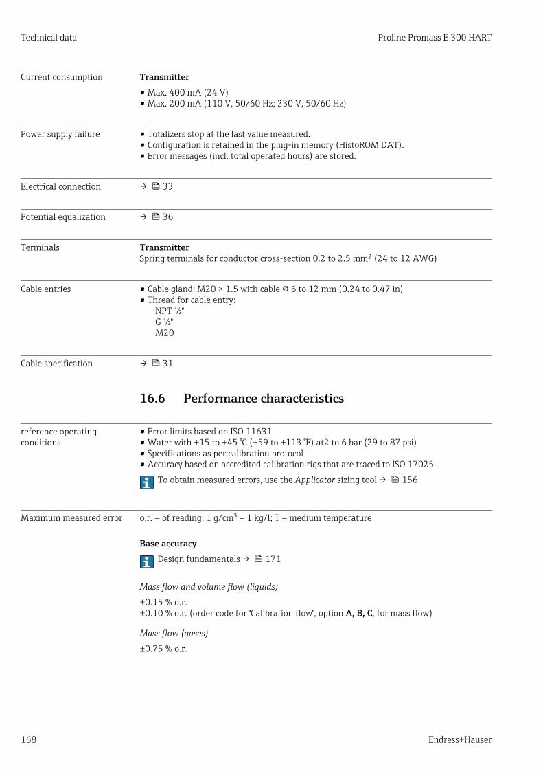
Technical data Proline Promass E 300 HART
168 Endress+Hauser
Current consumption Transmitter• Max. 400 mA (24 V)• Max. 200 mA (110 V, 50/60 Hz; 230 V, 50/60 Hz)
Power supply failure • Totalizers stop at the last value measured.• Configuration is retained in the plug-in memory (HistoROM DAT).• Error messages (incl. total operated hours) are stored.
Electrical connection → 33
Potential equalization → 36
Terminals TransmitterSpring terminals for conductor cross-section 0.2 to 2.5 mm2 (24 to 12 AWG)
Cable entries • Cable gland: M20 × 1.5 with cable 6 to 12 mm (0.24 to 0.47 in)• Thread for cable entry:
– NPT ½"– G ½"– M20
Cable specification → 31
16.6 Performance characteristics
reference operatingconditions
• Error limits based on ISO 11631• Water with +15 to +45 °C (+59 to +113 °F) at2 to 6 bar (29 to 87 psi)• Specifications as per calibration protocol• Accuracy based on accredited calibration rigs that are traced to ISO 17025.
To obtain measured errors, use the Applicator sizing tool → 156
Maximum measured error o.r. = of reading; 1 g/cm³ = 1 kg/l; T = medium temperature
Base accuracyDesign fundamentals → 171
Mass flow and volume flow (liquids)
±0.15 % o.r.±0.10 % o.r. (order code for "Calibration flow", option A, B, C, for mass flow)
Mass flow (gases)
±0.75 % o.r.
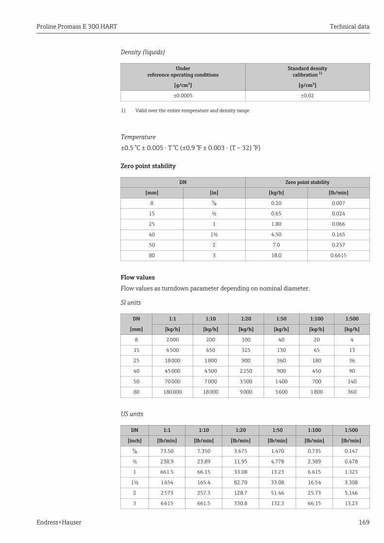
Proline Promass E 300 HART Technical data
Endress+Hauser 169
Density (liquids)
Underreference operating conditions
Standard densitycalibration 1)
[g/cm³] [g/cm³]
±0.0005 ±0.02
1) Valid over the entire temperature and density range
Temperature
±0.5 °C ± 0.005 · T °C (±0.9 °F ± 0.003 · (T – 32) °F)
Zero point stability
DN Zero point stability
[mm] [in] [kg/h] [lb/min]
8 ³⁄₈ 0.20 0.007
15 ½ 0.65 0.024
25 1 1.80 0.066
40 1½ 4.50 0.165
50 2 7.0 0.257
80 3 18.0 0.6615
Flow valuesFlow values as turndown parameter depending on nominal diameter.
SI units
DN 1:1 1:10 1:20 1:50 1:100 1:500
[mm] [kg/h] [kg/h] [kg/h] [kg/h] [kg/h] [kg/h]
8 2 000 200 100 40 20 4
15 6 500 650 325 130 65 13
25 18 000 1 800 900 360 180 36
40 45 000 4 500 2 250 900 450 90
50 70 000 7 000 3 500 1 400 700 140
80 180 000 18 000 9 000 3 600 1 800 360
US units
DN 1:1 1:10 1:20 1:50 1:100 1:500
[inch] [lb/min] [lb/min] [lb/min] [lb/min] [lb/min] [lb/min]
³⁄₈ 73.50 7.350 3.675 1.470 0.735 0.147
½ 238.9 23.89 11.95 4.778 2.389 0.478
1 661.5 66.15 33.08 13.23 6.615 1.323
1½ 1 654 165.4 82.70 33.08 16.54 3.308
2 2 573 257.3 128.7 51.46 25.73 5.146
3 6 615 661.5 330.8 132.3 66.15 13.23
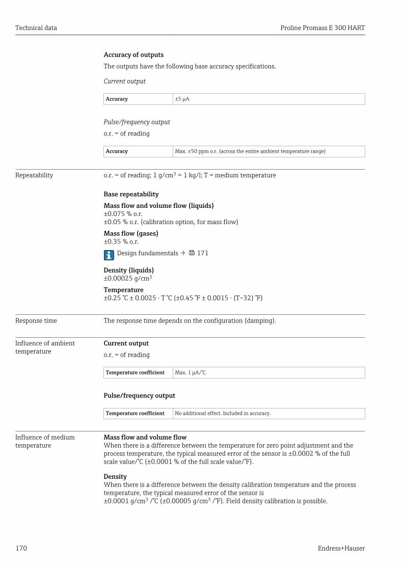
Technical data Proline Promass E 300 HART
170 Endress+Hauser
Accuracy of outputsThe outputs have the following base accuracy specifications.
Current output
Accuracy ±5 µA
Pulse/frequency output
o.r. = of reading
Accuracy Max. ±50 ppm o.r. (across the entire ambient temperature range)
Repeatability o.r. = of reading; 1 g/cm3 = 1 kg/l; T = medium temperature
Base repeatabilityMass flow and volume flow (liquids)±0.075 % o.r.±0.05 % o.r. (calibration option, for mass flow)
Mass flow (gases)±0.35 % o.r.
Design fundamentals → 171
Density (liquids)±0.00025 g/cm3
Temperature±0.25 °C ± 0.0025 · T °C (±0.45 °F ± 0.0015 · (T–32) °F)
Response time The response time depends on the configuration (damping).
Influence of ambienttemperature
Current outputo.r. = of reading
Temperature coefficient Max. 1 μA/°C
Pulse/frequency output
Temperature coefficient No additional effect. Included in accuracy.
Influence of mediumtemperature
Mass flow and volume flowWhen there is a difference between the temperature for zero point adjustment and theprocess temperature, the typical measured error of the sensor is ±0.0002 % of the fullscale value/°C (±0.0001 % of the full scale value/°F).
DensityWhen there is a difference between the density calibration temperature and the processtemperature, the typical measured error of the sensor is±0.0001 g/cm3 /°C (±0.00005 g/cm3 /°F). Field density calibration is possible.

Proline Promass E 300 HART Technical data
Endress+Hauser 171
[kg/m ]3
[°C]
-40 0-80 40 80 120 160 200 240 280 320 [°F]
-40 0 50 100 1500
2
4
6
8
10
14
12
A0016609
35 Field density calibration, for example at +20 °C (+68 °F)
Temperature±0.005 · T °C (± 0.005 · (T – 32) °F)
Influence of mediumpressure
The table below shows the effect on accuracy of mass flow due to a difference betweencalibration pressure and process pressure.
o.r. = of reading
DN [% o.r./bar] [% o.r./psi]
[mm] [in]
8 ³⁄₈ no influence
15 ½ no influence
25 1 no influence
40 1½ no influence
50 2 –0.009 –0.0006
80 3 –0.020 –0.0014
Design fundamentals o.r. = of reading, o.f.s. = of full scale value
BaseAccu = base accuracy in % o.r., BaseRepeat = base repeatability in % o.r.
MeasValue = measured value; ZeroPoint = zero point stability
Calculation of the maximum measured error as a function of the flow rate
Flow rate Maximum measured error in % o.r.
ZeroPoint
BaseAccu⋅ 100³
A0021332
± BaseAccu
A0021339
ZeroPoint
BaseAccu⋅ 100<
A0021333
ZeroPoint
MeasValue⋅ 100±
A0021334

Technical data Proline Promass E 300 HART
172 Endress+Hauser
Calculation of the maximum repeatability as a function of the flow rate
Flow rate Maximum repeatability in % o.r.
½ ⋅ ZeroPointBaseRepeat ⋅ 100³
A0021335 A0021340
½ ⋅ ZeroPointBaseRepeat ⋅ 100<
A0021336
ZeroPoint
MeasValue⋅ 100½ ⋅±
A0021337
Example for max. measured error
E [%]
Q [%]0 5 10 15 20 25 30 35 40 45 50 60 6555
0
0.5
1.0
1.5
2.0
2.5
70 75 80 85 90 95 100
A0030289
E Error: Maximum measured error as % o.r. (example)Q Flow rate as %
16.7 Installation"Mounting requirements" → 22
16.8 Environment
Ambient temperaturerange
→ 24
Temperature tablesObserve the interdependencies between the permitted ambient and fluidtemperatures when operating the device in hazardous areas.
For detailed information on the temperature tables, see the separate documententitled "Safety Instructions" (XA) for the device.
Storage temperature –50 to +80 °C (–58 to +176 °F)
Climate class DIN EN 60068-2-38 (test Z/AD)
Degree of protection Transmitter and sensor• As standard: IP66/67, type 4X enclosure• When housing is open: IP20, type 1 enclosure• Display module: IP20, type 1 enclosure
External WLAN antennaIP67
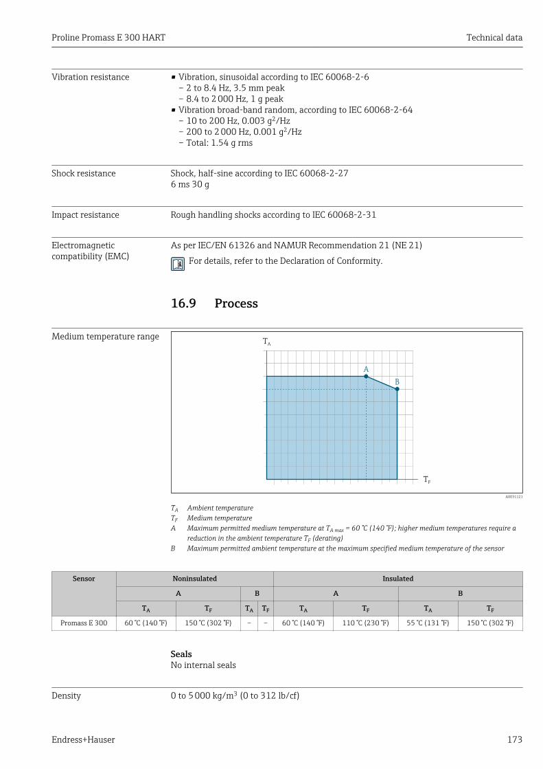
Proline Promass E 300 HART Technical data
Endress+Hauser 173
Vibration resistance • Vibration, sinusoidal according to IEC 60068-2-6– 2 to 8.4 Hz, 3.5 mm peak– 8.4 to 2 000 Hz, 1 g peak
• Vibration broad-band random, according to IEC 60068-2-64– 10 to 200 Hz, 0.003 g2/Hz– 200 to 2 000 Hz, 0.001 g2/Hz– Total: 1.54 g rms
Shock resistance Shock, half-sine according to IEC 60068-2-276 ms 30 g
Impact resistance Rough handling shocks according to IEC 60068-2-31
Electromagneticcompatibility (EMC)
As per IEC/EN 61326 and NAMUR Recommendation 21 (NE 21)
For details, refer to the Declaration of Conformity.
16.9 Process
Medium temperature rangeT
A
TF
B
A
A0031121
TA Ambient temperatureTF Medium temperatureA Maximum permitted medium temperature at TA max = 60 °C (140 °F); higher medium temperatures require a
reduction in the ambient temperature TF (derating)B Maximum permitted ambient temperature at the maximum specified medium temperature of the sensor
Sensor Noninsulated Insulated
A B A B
TA TF TA TF TA TF TA TF
Promass E 300 60 °C (140 °F) 150 °C (302 °F) – – 60 °C (140 °F) 110 °C (230 °F) 55 °C (131 °F) 150 °C (302 °F)
SealsNo internal seals
Density 0 to 5 000 kg/m3 (0 to 312 lb/cf)

Technical data Proline Promass E 300 HART
174 Endress+Hauser
Pressure-temperatureratings
An overview of the pressure-temperature ratings for the process connections isprovided in the "Technical Information" document
Secondary containmentpressure rating
The sensor housing is filled with dry inert gas and protects the electronics and mechanicsinside.
The housing does not have pressure vessel classification.
Reference value for the pressure loading capacity of the sensor housing: 16 bar (232 psi)
For information on the dimensions: see the "Mechanical construction" section of the"Technical Information" document
Rupture disk To increase the level of safety, a device version with a rupture disk with a trigger pressureof 10 to 15 bar (145 to 217.5 psi) can be used (order code for "Sensor option", option CA"rupture disk").
Rupture disks cannot be combined with the separately available heating jacket .
Special mounting instructions: → 26
Flow limit Select the nominal diameter by optimizing between the required flow range andpermissible pressure loss.
For an overview of the full scale values for the measuring range, see the "Measuringrange" section
• The minimum recommended full scale value is approx. 1/20 of the maximum full scalevalue
• In most applications, 20 to 50 % of the maximum full scale value can be considered ideal• A low full scale value must be selected for abrasive media (such as liquids with entrained
solids): flow velocity < 1 m/s (< 3 ft/s).• For gas measurement the following rules apply:
– The flow velocity in the measuring tubes should not exceed half the sound velocity(0.5 Mach).
– The maximum mass flow depends on the density of the gas: formula → 159
Pressure loss To calculate the pressure loss, use the Applicator sizing tool → 156
System pressure → 24
16.10 Mechanical construction
Design, dimensions For the dimensions and installation lengths of the device, see the "TechnicalInformation" document, "Mechanical construction" section
Weight Transmitter version for the hazardous area: +2 kg (+4.4 lbs)
All values (weight) refer to devices with EN/DIN PN 40 flanges.
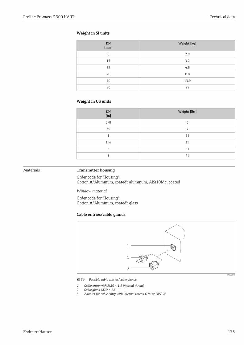
Proline Promass E 300 HART Technical data
Endress+Hauser 175
Weight in SI units
DN[mm]
Weight [kg]
8 2.9
15 3.2
25 4.8
40 8.8
50 13.9
80 29
Weight in US units
DN[in]
Weight [lbs]
3/8 6
½ 7
1 11
1 ½ 19
2 31
3 64
Materials Transmitter housingOrder code for "Housing":Option A "Aluminum, coated": aluminum, AlSi10Mg, coated
Window material
Order code for "Housing":Option A "Aluminum, coated": glass
Cable entries/cable glands
1
2
3
A0020640
36 Possible cable entries/cable glands
1 Cable entry with M20 × 1.5 internal thread2 Cable gland M20 × 1.53 Adapter for cable entry with internal thread G ½" or NPT ½"

Technical data Proline Promass E 300 HART
176 Endress+Hauser
Order code for "Housing", option A "Aluminum, coated"
The various cable entries are suitable for hazardous and non-hazardous areas.
Cable entry/cable gland Material
Cable gland M20 × 1.5 Plastic/nickel-plated brass
Adapter for cable entry with internal thread G ½" Nickel-plated brass
Adapter for cable entry with internal thread NPT ½"
Device plug coupling Plug M12 × 1• Socket: Stainless steel, 1.4404 (316L)• Contact housing: Polyamide• Contacts: Gold-plated brass
Device plug
Electrical connection Material
Plug M12x1 • Socket: Stainless steel, 1.4404 (316L)• Contact housing: Polyamide• Contacts: Gold-plated brass
Sensor housing• Acid and alkali-resistant outer surface• Stainless steel 1.4301 (304)
Measuring tubesStainless steel, 1.4539 (904L); manifold: stainless steel, 1.4404 (316L)
Process connections• Flanges according to EN 1092-1 (DIN2501) / according to ASME B 16.5 / as per JIS
B2220:Stainless steel, 1.4404 (F316/F316L)
• All other process connections:Stainless steel, 1.4404 (316/316L)
List of all available process connections → 177
SealsWelded process connections without internal seals
AccessoriesProtective cover
Stainless steel, 1.4404 (316L)
External WLAN antenna
• WLAN antenna:ASA plastic (acrylic ester-styrene-acrylonitrile) and nickel-plated brass
• Adapter:Stainless steel and copper
Proline Promass E 300 HART Technical data
Endress+Hauser 177
Process connections • Fixed flange connections:– EN 1092-1 (DIN 2501) flange– EN 1092-1 (DIN 2512N) flange– Namur lengths in accordance with NE 132– ASME B16.5 flange– JIS B2220 flange– DIN 11864-2 Form A flange, DIN11866 series A, flat flange
• Clamp connectionsTri-Clamp (OD tubes), DIN 11866 series C
• Threaded hygienic connection:– DIN 11851 threaded hygienic connection, DIN11866 series A– SMS 1145 threaded hygienic connection– ISO 2853 threaded hygienic connection, ISO2037– DIN 11864-1 Form A threaded hygienic connection, DIN11866 series A
• VCO connections– 8-VCO-4– 12-VCO-4
For information on the different materials used in the process connections → 176
Surface roughness All data relate to parts in contact with fluid.• Not polished• Ramax = 0.8 µm (32 µin)• Ramax = 0.4 µm (16 µin)
16.11 Operability
Languages Can be operated in the following languages:• Via local operation
English, German, French, Spanish, Italian, Dutch, Portuguese, Polish, Russian, Turkish,Chinese, Japanese, Korean, Arabic, Bahasa (Indonesian), Thai, Vietnamese, Czech,Swedish
• Via Web browserEnglish, German, French, Spanish, Italian, Dutch, Portuguese, Polish, Russian, Turkish,Chinese, Japanese, Korean, Arabic, Bahasa (Indonesian), Thai, Vietnamese, Czech,Swedish
• Via "FieldCare", "DeviceCare" operating tool: English, German, French, Spanish, Italian,Chinese, Japanese
Local operation Via display moduleTwo display modules are available:• Order code for "Display; operation", option F "4-line, backlit, graphic display; touch
control"• Order code for "Display; operation", option G "4-line, backlit, graphic display; touch
control + WLAN"
Information about WLAN interface → 63

Technical data Proline Promass E 300 HART
178 Endress+Hauser
A0026785
37 Operation with touch control
Display elements
• 4-line, illuminated, graphic display• White background lighting; switches to red in event of device errors• Format for displaying measured variables and status variables can be individually
configured• Permitted ambient temperature for the display: –20 to +60 °C (–4 to +140 °F)
The readability of the display may be impaired at temperatures outside the temperaturerange.
Operating elements
• External operation via touch control (3 optical keys) without opening the housing: ,,
• Operating elements also accessible in various hazardous areas
Via remote display and operating module DKX001The remote display and operating module DKX001 is available as an optional extra:Order code for "Display; operation", option O "Separate backlit, 4-line display; 10 m (30 ft)Cable; touch control"
Another device version, e.g. other housing material, other cable length etc., can beordered via the separate product structure DKX001. The measuring device is orderedwith:Order code for "Display; operation", option M "None, prepared for remote display"
A0026786
38 Operation via remote display and operating module DKX001
Proline Promass E 300 HART Technical data
Endress+Hauser 179
Display and operating elements
The display and operating elements correspond to those of the display module → 178.
• The measuring device is always supplied with a dummy cover when the remotedisplay and operating module DKX001 is used. Display or operation at thetransmitter is not possible in this case.
• The remote display and operating module DKX001 can also be ordered separatelyand subsequently as an accessory without a measuring device → 155.
• If ordered subsequently: The remote display and operating module DKX001 cannotbe connected at the same time as the existing display or operation unit. Only onedisplay or operation unit may be connected to the transmitter at any one time.
Material
The housing material of the display and operating module DKX001 depends on the choiceof transmitter housing material.
Transmitter housing Remote display and operating module
Order code for "Housing" Material Material
Option A "Aluminum, coated" AlSi10Mg, coated AlSi10Mg, coated
Cable entry
Corresponds to the choice of transmitter housing, order code for "Electrical connection".
Connecting cable
→ 32
Dimensions
For the dimensions, see the "Technical Information" document, "Mechanicalconstruction" section.
Remote operation → 62
Service interface → 63
Supported operating tools Different operating tools can be used for local or remote access to the measuring device.Depending on the operating tool used, access is possible with different operating units andvia a variety of interfaces.
Supported operatingtools
Operating unit Interface Additional information
Web browser Notebook, PC or tabletwith Web browser
• CDI-RJ45 serviceinterface
• WLAN interface
Special Documentation for thedevice → 186
DeviceCare SFE100 Notebook, PC or tabletwith Microsoft Windowssystem
• CDI-RJ45 serviceinterface
• WLAN interface• Fieldbus protocol
→ 156

Technical data Proline Promass E 300 HART
180 Endress+Hauser
Supported operatingtools
Operating unit Interface Additional information
FieldCare SFE500 Notebook, PC or tabletwith Microsoft Windowssystem
• CDI-RJ45 serviceinterface
• WLAN interface• Fieldbus protocol
→ 156
Device Xpert Field Xpert SFX100/350/370
HART andFOUNDATION Fieldbusfieldbus protocol
Operating InstructionsBA01202S
Device description files:Use update function ofhandheld terminal
Other operating tools based on FDT technology with a device driver such as DTM/iDTM or DD/EDD can be used for device operation. These operating tools are availablefrom the individual manufacturers. Integration into the following operating tools,among others, is supported:
• Process Device Manager (PDM) by Siemens → www.siemens.com• Asset Management Solutions (AMS) by Emerson → www.emersonprocess.com• FieldCommunicator 375/475 by Emerson → www.emersonprocess.com• Field Device Manager (FDM) by Honeywell → www.honeywellprocess.com• FieldMate by Yokogawa → www.yokogawa.com• PACTWare → www.pactware.com
The associated device description files are available at: www.endress.com →Downloads
Web serverThanks to the integrated Web server, the device can be operated and configured via a Webbrowser and via a service interface (CDI-RJ45) or a WLAN interface. The structure of theoperating menu is the same as for the local display. In addition to the measured values,status information on the device is also displayed and allows the user to monitor the statusof the device. Furthermore the measuring device data can be managed and the networkparameters can be configured. The WLAN connection requires a device that acts as anaccess point to enable communication via a computer or mobile handheld terminal.
Supported functionsData exchange between the operating unit (such as a notebook for example) and themeasuring device:– Uploading the configuration from the measuring device (XML format, configuration
backup)– Save the configuration to the measuring device (XML format, restore configuration)– Export event list (.csv file)– Export parameter settings (.csv file, create documentation of the measuring point
configuration)– Export the Heartbeat verification log (PDF file, only available with the "Heartbeat
Verification" application package)– Flash firmware version for device firmware upgrade, for instance
HistoROMdata management
The measuring device features HistoROM data management. HistoROM data managementcomprises both the storage and import/export of key device and process data, makingoperation and servicing far more reliable, secure and efficient.
When the device is delivered, the factory settings of the configuration data are storedas a backup in the device memory. This memory can be overwritten with an updateddata record, for example after commissioning.

Proline Promass E 300 HART Technical data
Endress+Hauser 181
Additional information on the data storage concept
There are different types of data storage units in which device data are stored and used by the device:
Device memory T-DAT S-DAT
Available data • Event history, such as diagnosticevents
• Parameter data record backup• Device firmware package• Driver for system integration e.g.:
DD for HART
• Measured value memory ("ExtendedHistoROM" order option)
• Current parameter data record (usedby firmware at run time)
• Maximum indicators (min/max values)• Totalizer values
• Sensor data: diameter etc.• Serial number• User-specific access code (to use the
"Maintenance" user role)• Calibration data• Device configuration (e.g. SW options, fixed
I/O or multi I/O)
Storage location Fixed on the user interface board inthe connection compartment
Can be plugged into the user interfaceboard in the connection compartment
In the sensor plug in the transmitter neck part
Data backupAutomatic• The most important device data (sensor and transmitter) are automatically saved in the
DAT modules• If the transmitter or measuring device is replaced: once the T-DAT containing the
previous device data has been exchanged, the new measuring device is ready foroperation again immediately without any errors
• If the sensor is replaced: once the sensor has been replaced, new sensor data aretransferred from the S-DAT in the measuring device and the measuring device is readyfor operation again immediately without any errors
ManualAdditional parameter data record (complete parameter settings) in the integrated devicememory for:• Data backup function
Backup and subsequent restoration of a device configuration in the device memory• Data comparison function
Comparison of the current device configuration with the device configuration saved inthe device memory
Data transferManualTransfer of a device configuration to another device using the export function of thespecific operating tool, e.g. with FieldCare, DeviceCare or Web server: to duplicate theconfiguration or to store in an archive (e.g. for backup purposes)
Event listAutomatic• Chronological display of up to 20 event messages in the events list• If the Extended HistoROM application package (order option) is enabled: up to 100
event messages are displayed in the events list along with a time stamp, plain textdescription and remedial measures
• The events list can be exported and displayed via a variety of interfaces and operatingtools e.g. DeviceCare, FieldCare or Web server
Technical data Proline Promass E 300 HART
182 Endress+Hauser
Data loggingManualIf the Extended HistoROM application package (order option) is enabled:• Record up to 1 000 measured values via 1 to 4 channels• User configurable recording interval• Record up to 250 measured values via each of the 4 memory channels• Export the measured value log via a variety of interfaces and operating tools e.g.
FieldCare, DeviceCare or Web server• Use the recorded measured value data in the integrated device simulation function in the
Diagnostics submenu (→ 145).
Service logbookManual• Create up to 20 user-specific events with a date and customized text in a separate
logbook for documentation of the measuring point• Use for calibration or service operations, for example, or for maintenance or revision
work that has been performed
16.12 Certificates and approvals
CE mark The measuring system is in conformity with the statutory requirements of the applicableEU Directives. These are listed in the corresponding EU Declaration of Conformity alongwith the standards applied.
Endress+Hauser confirms successful testing of the device by affixing to it the CE mark.
C-Tick symbol The measuring system meets the EMC requirements of the "Australian Communicationsand Media Authority (ACMA)".
Ex approval The devices are certified for use in hazardous areas and the relevant safety instructions areprovided in the separate "Safety Instructions" (XA) document. Reference is made to thisdocument on the nameplate.
Sanitary compatibility • 3-A approval• EHEDG-tested
Functional safety The measuring device can be used for flow monitoring systems (min., max., range) up toSIL 2 (single-channel architecture; order code for "Additional approval", option LA) and SIL3 (multichannel architecture with homogeneous redundancy) and is independentlyevaluated and certified by the TÜV in accordance with IEC 61508.
The following types of monitoring in safety equipment are possible:• Mass flow• Volume flow• Density
Functional Safety Manual with information on the SIL device → 186
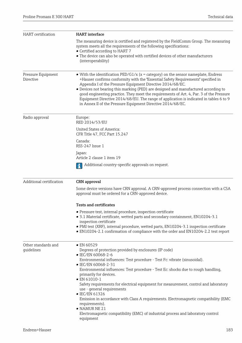
Proline Promass E 300 HART Technical data
Endress+Hauser 183
HART certification HART interfaceThe measuring device is certified and registered by the FieldComm Group. The measuringsystem meets all the requirements of the following specifications:• Certified according to HART 7• The device can also be operated with certified devices of other manufacturers
(interoperability)
Pressure EquipmentDirective
• With the identification PED/G1/x (x = category) on the sensor nameplate, Endress+Hauser confirms conformity with the "Essential Safety Requirements" specified inAppendix I of the Pressure Equipment Directive 2014/68/EC.
• Devices not bearing this marking (PED) are designed and manufactured according togood engineering practice. They meet the requirements of Art. 4, Par. 3 of the PressureEquipment Directive 2014/68/EU. The range of application is indicated in tables 6 to 9in Annex II of the Pressure Equipment Directive 2014/68/EC.
Radio approval Europe:RED 2014/53/EU
United States of America:CFR Title 47, FCC Part 15.247
Canada:RSS-247 Issue 1
Japan:Article 2 clause 1 item 19
Additional country-specific approvals on request.
Additional certification CRN approvalSome device versions have CRN approval. A CRN-approved process connection with a CSAapproval must be ordered for a CRN-approved device.
Tests and certificates• Pressure test, internal procedure, inspection certificate• 3.1 Material certificate, wetted parts and secondary containment, EN10204-3.1
inspection certificate• PMI test (XRF), internal procedure, wetted parts, EN10204-3.1 inspection certificate• EN10204-2.1 confirmation of compliance with the order and EN10204-2.2 test report
Other standards andguidelines
• EN 60529Degrees of protection provided by enclosures (IP code)
• IEC/EN 60068-2-6Environmental influences: Test procedure - Test Fc: vibrate (sinusoidal).
• IEC/EN 60068-2-31Environmental influences: Test procedure - Test Ec: shocks due to rough handling,primarily for devices.
• EN 61010-1Safety requirements for electrical equipment for measurement, control and laboratoryuse - general requirements
• IEC/EN 61326Emission in accordance with Class A requirements. Electromagnetic compatibility (EMCrequirements).
• NAMUR NE 21Electromagnetic compatibility (EMC) of industrial process and laboratory controlequipment

Technical data Proline Promass E 300 HART
184 Endress+Hauser
• NAMUR NE 32Data retention in the event of a power failure in field and control instruments withmicroprocessors
• NAMUR NE 43Standardization of the signal level for the breakdown information of digital transmitterswith analog output signal.
• NAMUR NE 53Software of field devices and signal-processing devices with digital electronics
• NAMUR NE 80The application of the pressure equipment directive to process control devices
• NAMUR NE 105Specifications for integrating fieldbus devices in engineering tools for field devices
• NAMUR NE 107Self-monitoring and diagnosis of field devices
• NAMUR NE 131Requirements for field devices for standard applications
• NAMUR NE 132Coriolis mass meter
• ETSI EN 300 328Guidelines for 2.4 GHz radio components.
• EN 301489Electromagnetic compatibility and radio spectrum matters (ERM).
16.13 Application packagesMany different application packages are available to enhance the functionality of thedevice. Such packages might be needed to address safety aspects or specific applicationrequirements.
The application packages can be ordered with the device or subsequently fromEndress+Hauser. Detailed information on the order code in question is available from yourlocal Endress+Hauser sales center or on the product page of the Endress+Hauser website:www.endress.com.
Detailed information on the application packages:Special Documentation for the device
Diagnostics functions Package Description
Extended HistoROM Comprises extended functions concerning the event log and the activation of themeasured value memory.
Event log:Memory volume is extended from 20 message entries (standard version) to up to100 entries.
Data logging (line recorder):• Memory capacity for up to 1000 measured values is activated.• 250 measured values can be output via each of the 4 memory channels. The
recording interval can be defined and configured by the user.• Measured value logs can be accessed via the local display or operating tool e.g.
FieldCare, DeviceCare or Web server.

Proline Promass E 300 HART Technical data
Endress+Hauser 185
Heartbeat Technology Package Description
Heartbeat Verification+Monitoring
Heartbeat MonitoringContinuously supplies data, which are characteristic of the measuring principle, toan external condition monitoring system for the purpose of preventivemaintenance or process analysis. These data enable the operator to:• Draw conclusions - using these data and other information - about the impact
process influences (such as corrosion, abrasion, buildup etc.) have on themeasuring performance over time.
• Schedule servicing in time.• Monitor the process or product quality, e.g. gas pockets.
Heartbeat VerificationMeets the requirement for traceable verification to DIN ISO 9001:2008 Chapter7.6 a) "Control of monitoring and measuring equipment".• Functional testing in the installed state without interrupting the process.• Traceable verification results on request, including a report.• Simple testing process via local operation or other operating interfaces.• Clear measuring point assessment (pass/fail) with high test coverage within the
framework of manufacturer specifications.• Extension of calibration intervals according to operator's risk assessment.
Concentration Package Description
ConcentrationMeasurement
Calculation and outputting of fluid concentrationsMany applications use density as a key measured value for monitoring quality orcontrolling processes. The device measures the density of the fluid as standard andmakes this value available to the control system.
With the help of the "Concentration Measurement" application package, themeasured density is used to calculate other process parameters:• Temperature-compensated density (reference density).• Percentage mass of the individual substances in a two-phase fluid.
(Concentration in %).• Fluid concentration is output with special units (°Brix, °Baumé, °API, etc.) for
standard applications.
16.14 AccessoriesOverview of accessories available for order → 155
16.15 Supplementary documentationFor an overview of the scope of the associated Technical Documentation, refer to thefollowing:• The W@M Device Viewer : Enter the serial number from the nameplate
(www.endress.com/deviceviewer)• The Endress+Hauser Operations App: Enter the serial number from the nameplate
or scan the 2-D matrix code (QR code) on the nameplate.
Standard documentation Brief Operating Instructions
Part 1 of 2: Sensor
Measuring device Documentation code
Proline Promass KA01212D

Technical data Proline Promass E 300 HART
186 Endress+Hauser
Part 2 of 2: Transmitter
Measuring device Documentation code
Proline 300 KA01226D
Technical Information
Measuring device Documentation code
Promass E 300 TI01272D
Description of device parameters
Measuring device Documentation code
Promass 300 GP01057D
Supplementary device-dependent documentation
Safety Instructions
Contents Documentation code
ATEX/IECEx Ex d/Ex de XA01405D
ATEX/IECEx Ex ec XA01439D
cCSAus XP XA01373D
cCSAus Ex d/ Ex de XA01372D
cCSAus Ex nA XA01507D
INMETRO Ex d/Ex de XA01468D
INMETRO Ex ec XA01470D
NEPSI Ex d/Ex de XA01469D
NEPSI Ex nA XA01471D
Remote display and operating module DKX001
Contents Documentation code
ATEX/IECEx Ex i XA01494D
ATEX/IECEx Ex ec XA01498D
cCSAus IS XA01499D
cCSAus Ex nA XA01513D
INMETRO Ex i XA01500D
INMETRO Ex ec XA01501D
NEPSI Ex i XA01502D
NEPSI Ex nA XA01503D
Special documentation
Contents Documentation code
Information on the Pressure Equipment Directive SD01614D
Functional Safety Manual SD01727D
Remote display and operating module DKX001 SD01763D
Web server SD01662D

Proline Promass E 300 HART Technical data
Endress+Hauser 187
Contents Documentation code
Heartbeat Technology SD01642D
Concentration measurement SD01644D
Installation Instructions
Contents Documentation code
Installation Instructions for spare part sets Overview of accessories available for order → 155

Index
188 Endress+Hauser
Index
AAccess authorization to parameters
Read access . . . . . . . . . . . . . . . . . . . . . . . . . . . . . 55Write access . . . . . . . . . . . . . . . . . . . . . . . . . . . . . 55
Access code . . . . . . . . . . . . . . . . . . . . . . . . . . . . . . . . 55Incorrect input . . . . . . . . . . . . . . . . . . . . . . . . . . . 55
Accuracy . . . . . . . . . . . . . . . . . . . . . . . . . . . . . . . . . 168Adapting the diagnostic behavior . . . . . . . . . . . . . . . 140Adapting the status signal . . . . . . . . . . . . . . . . . . . . 140Additional certification . . . . . . . . . . . . . . . . . . . . . . 183Ambient temperature range
Influence . . . . . . . . . . . . . . . . . . . . . . . . . . . . . . 170AMS Device Manager . . . . . . . . . . . . . . . . . . . . . . . . 66
Function . . . . . . . . . . . . . . . . . . . . . . . . . . . . . . . 66Application . . . . . . . . . . . . . . . . . . . . . . . . . . . . . . . 158Application packages . . . . . . . . . . . . . . . . . . . . . . . . 184Applicator . . . . . . . . . . . . . . . . . . . . . . . . . . . . . . . . 159Approvals . . . . . . . . . . . . . . . . . . . . . . . . . . . . . . . . 182
BBurst mode . . . . . . . . . . . . . . . . . . . . . . . . . . . . . . . . 70
CC-Tick symbol . . . . . . . . . . . . . . . . . . . . . . . . . . . . . 182Cable entries
Technical data . . . . . . . . . . . . . . . . . . . . . . . . . . 168Cable entry
Degree of protection . . . . . . . . . . . . . . . . . . . . . . . 41CE mark . . . . . . . . . . . . . . . . . . . . . . . . . . . . . . 11, 182Certificates . . . . . . . . . . . . . . . . . . . . . . . . . . . . . . . 182Check
Installation . . . . . . . . . . . . . . . . . . . . . . . . . . . . . 30Checklist
Post-connection check . . . . . . . . . . . . . . . . . . . . . 41Post-installation check . . . . . . . . . . . . . . . . . . . . . 30
CleaningCleaning in place (CIP) . . . . . . . . . . . . . . . . . . . . 152Exterior cleaning . . . . . . . . . . . . . . . . . . . . . . . . 152Interior cleaning . . . . . . . . . . . . . . . . . . . . . . . . . 152Sterilization in place (SIP) . . . . . . . . . . . . . . . . . . 152
Climate class . . . . . . . . . . . . . . . . . . . . . . . . . . . . . . 172Commissioning . . . . . . . . . . . . . . . . . . . . . . . . . . . . . 73
Advanced settings . . . . . . . . . . . . . . . . . . . . . . . 102Configuring the measuring device . . . . . . . . . . . . . 73
Communication-specific data . . . . . . . . . . . . . . . . . . . 68Connecting cable . . . . . . . . . . . . . . . . . . . . . . . . . . . . 31Connecting the measuring device . . . . . . . . . . . . . . . . 33Connecting the signal cables . . . . . . . . . . . . . . . . . . . 33Connecting the supply voltage cables . . . . . . . . . . . . . 33Connection
see Electrical connectionConnection preparations . . . . . . . . . . . . . . . . . . . . . . 33Connection tools . . . . . . . . . . . . . . . . . . . . . . . . . . . . 31Context menu
Calling up . . . . . . . . . . . . . . . . . . . . . . . . . . . . . . 50Closing . . . . . . . . . . . . . . . . . . . . . . . . . . . . . . . . . 50
Explanation . . . . . . . . . . . . . . . . . . . . . . . . . . . . . 50Current consumption . . . . . . . . . . . . . . . . . . . . . . . . 168
DDeclaration of Conformity . . . . . . . . . . . . . . . . . . . . . 11Define access code . . . . . . . . . . . . . . . . . . . . . . . . . . 118Degree of protection . . . . . . . . . . . . . . . . . . . . . 41, 172Density . . . . . . . . . . . . . . . . . . . . . . . . . . . . . . . . . . 173Design fundamentals
Maximum measured error . . . . . . . . . . . . . . . . . 171Repeatability . . . . . . . . . . . . . . . . . . . . . . . . . . . 171
Designated use . . . . . . . . . . . . . . . . . . . . . . . . . . . . . 10Device components . . . . . . . . . . . . . . . . . . . . . . . . . . 14Device description files . . . . . . . . . . . . . . . . . . . . . . . 68Device documentation
Supplementary documentation . . . . . . . . . . . . . . . . 8Device locking, status . . . . . . . . . . . . . . . . . . . . . . . 120Device name
Sensor . . . . . . . . . . . . . . . . . . . . . . . . . . . . . . . . . 18Transmitter . . . . . . . . . . . . . . . . . . . . . . . . . . . . . 17
Device repair . . . . . . . . . . . . . . . . . . . . . . . . . . . . . . 153Device revision . . . . . . . . . . . . . . . . . . . . . . . . . . . . . 68Device type ID . . . . . . . . . . . . . . . . . . . . . . . . . . . . . . 68DeviceCare . . . . . . . . . . . . . . . . . . . . . . . . . . . . . . . . 66
Device description file . . . . . . . . . . . . . . . . . . . . . . 68Diagnostic behavior
Explanation . . . . . . . . . . . . . . . . . . . . . . . . . . . . 136Symbols . . . . . . . . . . . . . . . . . . . . . . . . . . . . . . . 136
Diagnostic informationDesign, description . . . . . . . . . . . . . . . . . . . 136, 139DeviceCare . . . . . . . . . . . . . . . . . . . . . . . . . . . . . 139FieldCare . . . . . . . . . . . . . . . . . . . . . . . . . . . . . . 139Light emitting diodes . . . . . . . . . . . . . . . . . . . . . 133Local display . . . . . . . . . . . . . . . . . . . . . . . . . . . 135Overview . . . . . . . . . . . . . . . . . . . . . . . . . . . . . . 141Remedial measures . . . . . . . . . . . . . . . . . . . . . . 141Web browser . . . . . . . . . . . . . . . . . . . . . . . . . . . 137
Diagnostic list . . . . . . . . . . . . . . . . . . . . . . . . . . . . . 146Diagnostic message . . . . . . . . . . . . . . . . . . . . . . . . . 135Diagnostics
Symbols . . . . . . . . . . . . . . . . . . . . . . . . . . . . . . . 135DIP switches
see Write protection switchDirect access . . . . . . . . . . . . . . . . . . . . . . . . . . . . . . . 52Direct access code . . . . . . . . . . . . . . . . . . . . . . . . . . . 47Disabling write protection . . . . . . . . . . . . . . . . . . . . 117Display
see Local displayDisplay and operating module DKX001 . . . . . . . . . . 178Display area
For operational display . . . . . . . . . . . . . . . . . . . . . 45In the navigation view . . . . . . . . . . . . . . . . . . . . . 47
Display valuesFor locking status . . . . . . . . . . . . . . . . . . . . . . . . 120
Disposal . . . . . . . . . . . . . . . . . . . . . . . . . . . . . . . . . 154

Index
Endress+Hauser 189
DocumentFunction . . . . . . . . . . . . . . . . . . . . . . . . . . . . . . . . 6Symbols used . . . . . . . . . . . . . . . . . . . . . . . . . . . . . 6
Document function . . . . . . . . . . . . . . . . . . . . . . . . . . . 6Down pipe . . . . . . . . . . . . . . . . . . . . . . . . . . . . . . . . . 22
EElectrical connection
Commubox FXA195 (USB) . . . . . . . . . . . . . . . . . . 62Computer with Web browser (e.g. InternetExplorer) . . . . . . . . . . . . . . . . . . . . . . . . . . . . . . . 62Degree of protection . . . . . . . . . . . . . . . . . . . . . . . 41Field Communicator 475 . . . . . . . . . . . . . . . . . . . 62Field Xpert SFX350/SFX370 . . . . . . . . . . . . . . . . . 62Measuring device . . . . . . . . . . . . . . . . . . . . . . . . . 31Operating tool (e.g. FieldCare, AMS DeviceManager, SIMATIC PDM) . . . . . . . . . . . . . . . . . . . 62Operating tools
Via HART protocol . . . . . . . . . . . . . . . . . . . . . . 62Via service interface (CDI-RJ45) . . . . . . . . . . . . 63Via WLAN interface . . . . . . . . . . . . . . . . . . . . 63
VIATOR Bluetooth modem . . . . . . . . . . . . . . . . . . 62Web server . . . . . . . . . . . . . . . . . . . . . . . . . . . . . 63WLAN interface . . . . . . . . . . . . . . . . . . . . . . . . . . 63
Electromagnetic compatibility . . . . . . . . . . . . . . . . . 173Electronics module . . . . . . . . . . . . . . . . . . . . . . . . . . 14Enabling write protection . . . . . . . . . . . . . . . . . . . . 117Endress+Hauser services
Maintenance . . . . . . . . . . . . . . . . . . . . . . . . . . . 152Repair . . . . . . . . . . . . . . . . . . . . . . . . . . . . . . . . 153
EnvironmentImpact resistance . . . . . . . . . . . . . . . . . . . . . . . . 173Shock resistance . . . . . . . . . . . . . . . . . . . . . . . . . 173Storage temperature . . . . . . . . . . . . . . . . . . . . . . 172Vibration resistance . . . . . . . . . . . . . . . . . . . . . . 173
Error messagessee Diagnostic messages
Event history . . . . . . . . . . . . . . . . . . . . . . . . . . . . . . 146Event list . . . . . . . . . . . . . . . . . . . . . . . . . . . . . . . . . 146Ex approval . . . . . . . . . . . . . . . . . . . . . . . . . . . . . . . 182Extended order code
Sensor . . . . . . . . . . . . . . . . . . . . . . . . . . . . . . . . . 18Transmitter . . . . . . . . . . . . . . . . . . . . . . . . . . . . . 17
Exterior cleaning . . . . . . . . . . . . . . . . . . . . . . . . . . . 152
FField Communicator
Function . . . . . . . . . . . . . . . . . . . . . . . . . . . . . . . 67Field Communicator 475 . . . . . . . . . . . . . . . . . . . . . . 67Field of application
Residual risks . . . . . . . . . . . . . . . . . . . . . . . . . . . . 11Field Xpert
Function . . . . . . . . . . . . . . . . . . . . . . . . . . . . . . . 64Field Xpert SFX350 . . . . . . . . . . . . . . . . . . . . . . . . . . 64FieldCare . . . . . . . . . . . . . . . . . . . . . . . . . . . . . . . . . 65
Device description file . . . . . . . . . . . . . . . . . . . . . . 68Establishing a connection . . . . . . . . . . . . . . . . . . . 65Function . . . . . . . . . . . . . . . . . . . . . . . . . . . . . . . 65User interface . . . . . . . . . . . . . . . . . . . . . . . . . . . 66
Filtering the event logbook . . . . . . . . . . . . . . . . . . . 147Firmware
Release date . . . . . . . . . . . . . . . . . . . . . . . . . . . . . 68Version . . . . . . . . . . . . . . . . . . . . . . . . . . . . . . . . 68
Firmware history . . . . . . . . . . . . . . . . . . . . . . . . . . . 151Flow direction . . . . . . . . . . . . . . . . . . . . . . . . . . . 23, 28Flow limit . . . . . . . . . . . . . . . . . . . . . . . . . . . . . . . . 174Function check . . . . . . . . . . . . . . . . . . . . . . . . . . . . . 73Function scope
AMS Device Manager . . . . . . . . . . . . . . . . . . . . . . 66Field Communicator . . . . . . . . . . . . . . . . . . . . . . 67Field Communicator 475 . . . . . . . . . . . . . . . . . . . 67Field Xpert . . . . . . . . . . . . . . . . . . . . . . . . . . . . . . 64SIMATIC PDM . . . . . . . . . . . . . . . . . . . . . . . . . . . 67
Functional safety (SIL) . . . . . . . . . . . . . . . . . . . . . . . 182Functions . . . . . . . . . . . . . . . . . . . . . . . . . . . . . . . . . 73
GGalvanic isolation . . . . . . . . . . . . . . . . . . . . . . . . . . 166
HHardware write protection . . . . . . . . . . . . . . . . . . . . 119HART certification . . . . . . . . . . . . . . . . . . . . . . . . . . 183HART protocol
Device variables . . . . . . . . . . . . . . . . . . . . . . . . . . 68Measured variables . . . . . . . . . . . . . . . . . . . . . . . 68
Help textCalling up . . . . . . . . . . . . . . . . . . . . . . . . . . . . . . 53Closing . . . . . . . . . . . . . . . . . . . . . . . . . . . . . . . . . 53Explanation . . . . . . . . . . . . . . . . . . . . . . . . . . . . . 53
HistoROM . . . . . . . . . . . . . . . . . . . . . . . . . . . . . . . . 111
IIdentifying the measuring device . . . . . . . . . . . . . . . . 16Impact resistance . . . . . . . . . . . . . . . . . . . . . . . . . . 173Incoming acceptance . . . . . . . . . . . . . . . . . . . . . . . . . 15Influence
Ambient temperature range . . . . . . . . . . . . . . . . 170Medium pressure . . . . . . . . . . . . . . . . . . . . . . . . 171Medium temperature . . . . . . . . . . . . . . . . . . . . . 170
Information on the document . . . . . . . . . . . . . . . . . . . 6Inlet runs . . . . . . . . . . . . . . . . . . . . . . . . . . . . . . . . . 24Input . . . . . . . . . . . . . . . . . . . . . . . . . . . . . . . . . . . 159Input mask . . . . . . . . . . . . . . . . . . . . . . . . . . . . . . . . 48Inspection
Received goods . . . . . . . . . . . . . . . . . . . . . . . . . . . 15Inspection check
Connection . . . . . . . . . . . . . . . . . . . . . . . . . . . . . . 41Installation . . . . . . . . . . . . . . . . . . . . . . . . . . . . . . . . 22Installation conditions
Down pipe . . . . . . . . . . . . . . . . . . . . . . . . . . . . . . 22Inlet and outlet runs . . . . . . . . . . . . . . . . . . . . . . . 24Mounting location . . . . . . . . . . . . . . . . . . . . . . . . 22Orientation . . . . . . . . . . . . . . . . . . . . . . . . . . . . . 23Rupture disk . . . . . . . . . . . . . . . . . . . . . . . . . . . . . 26Sensor heating . . . . . . . . . . . . . . . . . . . . . . . . . . . 26System pressure . . . . . . . . . . . . . . . . . . . . . . . . . . 24Thermal insulation . . . . . . . . . . . . . . . . . . . . . . . . 25Vibrations . . . . . . . . . . . . . . . . . . . . . . . . . . . . . . 26

Index
190 Endress+Hauser
Installation dimensions . . . . . . . . . . . . . . . . . . . . . . . 24Interior cleaning . . . . . . . . . . . . . . . . . . . . . . . . . . . 152
KKeypad lock
Disabling . . . . . . . . . . . . . . . . . . . . . . . . . . . . . . . 55Enabling . . . . . . . . . . . . . . . . . . . . . . . . . . . . . . . 55
LLanguages, operation options . . . . . . . . . . . . . . . . . 177Line recorder . . . . . . . . . . . . . . . . . . . . . . . . . . . . . . 128Local display . . . . . . . . . . . . . . . . . . . . . . . . . . . . . . 177
Editing view . . . . . . . . . . . . . . . . . . . . . . . . . . . . . 48Navigation view . . . . . . . . . . . . . . . . . . . . . . . . . . 46see Diagnostic messagesee In alarm conditionsee Operational display
Low flow cut off . . . . . . . . . . . . . . . . . . . . . . . . . . . 166
MMain electronics module . . . . . . . . . . . . . . . . . . . . . . 14Maintenance tasks . . . . . . . . . . . . . . . . . . . . . . . . . 152Managing the device configuration . . . . . . . . . . . . . 111Manufacturer ID . . . . . . . . . . . . . . . . . . . . . . . . . . . . 68Manufacturing date . . . . . . . . . . . . . . . . . . . . . . . 17, 18Materials . . . . . . . . . . . . . . . . . . . . . . . . . . . . . . . . 175Maximum measured error . . . . . . . . . . . . . . . . . . . . 168Measured values
see Process variablesMeasuring and test equipment . . . . . . . . . . . . . . . . 152Measuring device
Configuration . . . . . . . . . . . . . . . . . . . . . . . . . . . . 73Conversion . . . . . . . . . . . . . . . . . . . . . . . . . . . . . 153Disposal . . . . . . . . . . . . . . . . . . . . . . . . . . . . . . . 154Mounting the sensor . . . . . . . . . . . . . . . . . . . . . . 28Preparing for electrical connection . . . . . . . . . . . . 33Preparing for mounting . . . . . . . . . . . . . . . . . . . . 28Removing . . . . . . . . . . . . . . . . . . . . . . . . . . . . . . 154Repairs . . . . . . . . . . . . . . . . . . . . . . . . . . . . . . . 153Structure . . . . . . . . . . . . . . . . . . . . . . . . . . . . . . . 14Switch-on . . . . . . . . . . . . . . . . . . . . . . . . . . . . . . 73
Measuring principle . . . . . . . . . . . . . . . . . . . . . . . . 158Measuring range
Calculation example for gas . . . . . . . . . . . . . . . . 160For gases . . . . . . . . . . . . . . . . . . . . . . . . . . . . . . 159For liquids . . . . . . . . . . . . . . . . . . . . . . . . . . . . . 159
Measuring range, recommended . . . . . . . . . . . . . . . 174Measuring system . . . . . . . . . . . . . . . . . . . . . . . . . . 158Medium pressure
Influence . . . . . . . . . . . . . . . . . . . . . . . . . . . . . . 171Medium temperature
Influence . . . . . . . . . . . . . . . . . . . . . . . . . . . . . . 170Menu
Diagnostics . . . . . . . . . . . . . . . . . . . . . . . . . . . . 145Setup . . . . . . . . . . . . . . . . . . . . . . . . . . . . . . . . . . 75
MenusFor measuring device configuration . . . . . . . . . . . . 73For specific settings . . . . . . . . . . . . . . . . . . . . . . 102
Mounting dimensionssee Installation dimensions
Mounting location . . . . . . . . . . . . . . . . . . . . . . . . . . . 22Mounting preparations . . . . . . . . . . . . . . . . . . . . . . . 28Mounting requirements
Installation dimensions . . . . . . . . . . . . . . . . . . . . 24Mounting tools . . . . . . . . . . . . . . . . . . . . . . . . . . . . . 28
NNameplate
Sensor . . . . . . . . . . . . . . . . . . . . . . . . . . . . . . . . . 18Transmitter . . . . . . . . . . . . . . . . . . . . . . . . . . . . . 17
Navigation path (navigation view) . . . . . . . . . . . . . . . 46Navigation view
In the submenu . . . . . . . . . . . . . . . . . . . . . . . . . . 46In the wizard . . . . . . . . . . . . . . . . . . . . . . . . . . . . 46
Nominal pressureSecondary containment . . . . . . . . . . . . . . . . . . . 174
Numeric editor . . . . . . . . . . . . . . . . . . . . . . . . . . . . . 48
OOperable flow range . . . . . . . . . . . . . . . . . . . . . . . . 160Operating elements . . . . . . . . . . . . . . . . . . . . . . 50, 136Operating keys
see Operating elementsOperating menu
Menus, submenus . . . . . . . . . . . . . . . . . . . . . . . . 43Structure . . . . . . . . . . . . . . . . . . . . . . . . . . . . . . . 43Submenus and user roles . . . . . . . . . . . . . . . . . . . 44
Operating philosophy . . . . . . . . . . . . . . . . . . . . . . . . 44Operation . . . . . . . . . . . . . . . . . . . . . . . . . . . . . . . . 120Operation options . . . . . . . . . . . . . . . . . . . . . . . . . . . 42Operational display . . . . . . . . . . . . . . . . . . . . . . . . . . 45Operational safety . . . . . . . . . . . . . . . . . . . . . . . . . . . 11Order code . . . . . . . . . . . . . . . . . . . . . . . . . . . . . 17, 18Orientation (vertical, horizontal) . . . . . . . . . . . . . . . . 23Outlet runs . . . . . . . . . . . . . . . . . . . . . . . . . . . . . . . . 24Output . . . . . . . . . . . . . . . . . . . . . . . . . . . . . . . . . . 162Output signal . . . . . . . . . . . . . . . . . . . . . . . . . . . . . 162
PPackaging disposal . . . . . . . . . . . . . . . . . . . . . . . . . . 21Parameter settings
Administration (Submenu) . . . . . . . . . . . . . . . . . 114Advanced setup (Submenu) . . . . . . . . . . . . . . . . 103Burst configuration 1 to n (Submenu) . . . . . . . . . . 70Calculated values (Submenu) . . . . . . . . . . . . . . . 103Configuration backup (Submenu) . . . . . . . . . . . . 111Current input . . . . . . . . . . . . . . . . . . . . . . . . . . . . 80Current input (Wizard) . . . . . . . . . . . . . . . . . . . . . 80Current input 1 to n (Submenu) . . . . . . . . . . . . . 123Current output . . . . . . . . . . . . . . . . . . . . . . . . . . . 82Current output (Wizard) . . . . . . . . . . . . . . . . . . . . 82Data logging (Submenu) . . . . . . . . . . . . . . . . . . . 128Define access code (Wizard) . . . . . . . . . . . . . . . . 113Device information (Submenu) . . . . . . . . . . . . . . 149Diagnostics (Menu) . . . . . . . . . . . . . . . . . . . . . . 145Display (Submenu) . . . . . . . . . . . . . . . . . . . . . . . 107Display (Wizard) . . . . . . . . . . . . . . . . . . . . . . . . . 97
Index
Endress+Hauser 191
Double pulse output . . . . . . . . . . . . . . . . . . . . . . . 96Double pulse output (Submenu) . . . . . . . . . . 96, 126I/O configuration . . . . . . . . . . . . . . . . . . . . . . . . . 79I/O configuration (Submenu) . . . . . . . . . . . . . . . . 79Low flow cut off (Wizard) . . . . . . . . . . . . . . . . . . 100Measured variables (Submenu) . . . . . . . . . . . . . . 121Partially filled pipe detection (Wizard) . . . . . . . . 101Pulse/frequency/switch output . . . . . . . . . . . . . . . 85Pulse/frequency/switch output (Wizard) . . 85, 87, 92Pulse/frequency/switch output 1 to n (Submenu) 125Relay output . . . . . . . . . . . . . . . . . . . . . . . . . . . . . 94Relay output 1 to n (Submenu) . . . . . . . . . . . . . . 125Relay output 1 to n (Wizard) . . . . . . . . . . . . . . . . . 94Reset access code (Submenu) . . . . . . . . . . . . . . . 114Select medium (Wizard) . . . . . . . . . . . . . . . . . . . . 78Sensor adjustment (Submenu) . . . . . . . . . . . . . . 104Setup (Menu) . . . . . . . . . . . . . . . . . . . . . . . . . . . . 75Simulation (Submenu) . . . . . . . . . . . . . . . . . . . . 114Status input . . . . . . . . . . . . . . . . . . . . . . . . . . . . . 81Status input (Submenu) . . . . . . . . . . . . . . . . . . . . 81Status input 1 to n (Submenu) . . . . . . . . . . . . . . 123System units (Submenu) . . . . . . . . . . . . . . . . . . . . 75Totalizer (Submenu) . . . . . . . . . . . . . . . . . . . . . . 122Totalizer 1 to n (Submenu) . . . . . . . . . . . . . . . . . 105Totalizer handling (Submenu) . . . . . . . . . . . . . . . 126Value current output 1 to n (Submenu) . . . . . . . . 124Web server (Submenu) . . . . . . . . . . . . . . . . . . . . . 61WLAN Settings (Submenu) . . . . . . . . . . . . . . . . . 110Zero point adjustment (Submenu) . . . . . . . . . . . . 105
ParametersChanging . . . . . . . . . . . . . . . . . . . . . . . . . . . . . . . 54Enter a value . . . . . . . . . . . . . . . . . . . . . . . . . . . . 54
Performance characteristics . . . . . . . . . . . . . . . . . . . 168Post-connection check (checklist) . . . . . . . . . . . . . . . 41Post-installation check . . . . . . . . . . . . . . . . . . . . . . . 73Post-installation check (checklist) . . . . . . . . . . . . . . . 30Potential equalization . . . . . . . . . . . . . . . . . . . . . . . . 36Power consumption . . . . . . . . . . . . . . . . . . . . . . . . . 167Power supply failure . . . . . . . . . . . . . . . . . . . . . . . . 168Pressure Equipment Directive . . . . . . . . . . . . . . . . . 183Pressure loss . . . . . . . . . . . . . . . . . . . . . . . . . . . . . . 174Pressure-temperature ratings . . . . . . . . . . . . . . . . . 174Process connections . . . . . . . . . . . . . . . . . . . . . . . . 177Process variables
Calculated . . . . . . . . . . . . . . . . . . . . . . . . . . . . . 159Measured . . . . . . . . . . . . . . . . . . . . . . . . . . . . . . 159
Product safety . . . . . . . . . . . . . . . . . . . . . . . . . . . . . . 11Protecting parameter settings . . . . . . . . . . . . . . . . . 117
RRadio approval . . . . . . . . . . . . . . . . . . . . . . . . . . . . 183Read access . . . . . . . . . . . . . . . . . . . . . . . . . . . . . . . . 55Reading measured values . . . . . . . . . . . . . . . . . . . . 120Recalibration . . . . . . . . . . . . . . . . . . . . . . . . . . . . . . 152reference operating conditions . . . . . . . . . . . . . . . . . 168Registered trademarks . . . . . . . . . . . . . . . . . . . . . . . . . 9Remedial measures
Calling up . . . . . . . . . . . . . . . . . . . . . . . . . . . . . 137Closing . . . . . . . . . . . . . . . . . . . . . . . . . . . . . . . 137
Remote operation . . . . . . . . . . . . . . . . . . . . . . . . . . 179Repair of a device . . . . . . . . . . . . . . . . . . . . . . . . . . 153Repairs . . . . . . . . . . . . . . . . . . . . . . . . . . . . . . . . . . 153
Notes . . . . . . . . . . . . . . . . . . . . . . . . . . . . . . . . . 153Repeatability . . . . . . . . . . . . . . . . . . . . . . . . . . . . . . 170Replacement
Device components . . . . . . . . . . . . . . . . . . . . . . . 153Requirements for personnel . . . . . . . . . . . . . . . . . . . . 10Response time . . . . . . . . . . . . . . . . . . . . . . . . . . . . . 170Return . . . . . . . . . . . . . . . . . . . . . . . . . . . . . . . . . . 153Rupture disk
Safety instructions . . . . . . . . . . . . . . . . . . . . . . . . 26Triggering pressure . . . . . . . . . . . . . . . . . . . . . . 174
SSafety . . . . . . . . . . . . . . . . . . . . . . . . . . . . . . . . . . . . 10Sanitary compatibility . . . . . . . . . . . . . . . . . . . . . . . 182Seals
Medium temperature range . . . . . . . . . . . . . . . . 173Sensor
Mounting . . . . . . . . . . . . . . . . . . . . . . . . . . . . . . . 28Sensor heating . . . . . . . . . . . . . . . . . . . . . . . . . . . . . 26Serial number . . . . . . . . . . . . . . . . . . . . . . . . . . . 17, 18Setting the operating language . . . . . . . . . . . . . . . . . 73Settings
Adapting the measuring device to the processconditions . . . . . . . . . . . . . . . . . . . . . . . . . . . . . 126Administration . . . . . . . . . . . . . . . . . . . . . . . . . . 113Advanced display configurations . . . . . . . . . . . . . 107Current input . . . . . . . . . . . . . . . . . . . . . . . . . . . . 80Current output . . . . . . . . . . . . . . . . . . . . . . . . . . . 82Device reset . . . . . . . . . . . . . . . . . . . . . . . . . . . . 149Device tag . . . . . . . . . . . . . . . . . . . . . . . . . . . . . . 75Double pulse output . . . . . . . . . . . . . . . . . . . . . . . 96I/O configuration . . . . . . . . . . . . . . . . . . . . . . . . . 79Local display . . . . . . . . . . . . . . . . . . . . . . . . . . . . 97Low flow cut off . . . . . . . . . . . . . . . . . . . . . . . . . 100Managing the device configuration . . . . . . . . . . . 111Medium . . . . . . . . . . . . . . . . . . . . . . . . . . . . . . . . 78Operating language . . . . . . . . . . . . . . . . . . . . . . . 73Partial filled pipe detection . . . . . . . . . . . . . . . . . 101Pulse output . . . . . . . . . . . . . . . . . . . . . . . . . . . . . 85Pulse/frequency/switch output . . . . . . . . . . . . 85, 87Relay output . . . . . . . . . . . . . . . . . . . . . . . . . . . . . 94Resetting the totalizer . . . . . . . . . . . . . . . . . . . . 126Sensor adjustment . . . . . . . . . . . . . . . . . . . . . . . 104Simulation . . . . . . . . . . . . . . . . . . . . . . . . . . . . . 114Status input . . . . . . . . . . . . . . . . . . . . . . . . . . . . . 81Switch output . . . . . . . . . . . . . . . . . . . . . . . . . . . . 92System units . . . . . . . . . . . . . . . . . . . . . . . . . . . . 75Totalizer . . . . . . . . . . . . . . . . . . . . . . . . . . . . . . 105Totalizer reset . . . . . . . . . . . . . . . . . . . . . . . . . . 126WLAN . . . . . . . . . . . . . . . . . . . . . . . . . . . . . . . . 110
Shock resistance . . . . . . . . . . . . . . . . . . . . . . . . . . . 173Showing data logging . . . . . . . . . . . . . . . . . . . . . . . 128Signal on alarm . . . . . . . . . . . . . . . . . . . . . . . . . . . . 165SIL (functional safety) . . . . . . . . . . . . . . . . . . . . . . . 182SIMATIC PDM . . . . . . . . . . . . . . . . . . . . . . . . . . . . . . 67
Function . . . . . . . . . . . . . . . . . . . . . . . . . . . . . . . 67
Index
192 Endress+Hauser
Software release . . . . . . . . . . . . . . . . . . . . . . . . . . . . 68Spare part . . . . . . . . . . . . . . . . . . . . . . . . . . . . . . . . 153Spare parts . . . . . . . . . . . . . . . . . . . . . . . . . . . . . . . 153Special connection instructions . . . . . . . . . . . . . . . . . 37Standards and guidelines . . . . . . . . . . . . . . . . . . . . . 183Status area
For operational display . . . . . . . . . . . . . . . . . . . . . 45In the navigation view . . . . . . . . . . . . . . . . . . . . . 47
Status signals . . . . . . . . . . . . . . . . . . . . . . . . . 135, 138Storage conditions . . . . . . . . . . . . . . . . . . . . . . . . . . . 20Storage temperature . . . . . . . . . . . . . . . . . . . . . . . . . 20Storage temperature range . . . . . . . . . . . . . . . . . . . 172Structure
Measuring device . . . . . . . . . . . . . . . . . . . . . . . . . 14Operating menu . . . . . . . . . . . . . . . . . . . . . . . . . . 43
SubmenuAdministration . . . . . . . . . . . . . . . . . . . . . . 113, 114Advanced setup . . . . . . . . . . . . . . . . . . . . . 102, 103Burst configuration 1 to n . . . . . . . . . . . . . . . . . . . 70Calculated values . . . . . . . . . . . . . . . . . . . . . . . . 103Configuration backup . . . . . . . . . . . . . . . . . . . . . 111Current input 1 to n . . . . . . . . . . . . . . . . . . . . . . 123Data logging . . . . . . . . . . . . . . . . . . . . . . . . . . . 128Device information . . . . . . . . . . . . . . . . . . . . . . . 149Display . . . . . . . . . . . . . . . . . . . . . . . . . . . . . . . . 107Double pulse output . . . . . . . . . . . . . . . . . . . 96, 126Event list . . . . . . . . . . . . . . . . . . . . . . . . . . . . . . 146I/O configuration . . . . . . . . . . . . . . . . . . . . . . . . . 79Input values . . . . . . . . . . . . . . . . . . . . . . . . . . . . 123Measured values . . . . . . . . . . . . . . . . . . . . . . . . 120Measured variables . . . . . . . . . . . . . . . . . . . . . . 121Output values . . . . . . . . . . . . . . . . . . . . . . . . . . . 124Overview . . . . . . . . . . . . . . . . . . . . . . . . . . . . . . . 44Process variables . . . . . . . . . . . . . . . . . . . . . . . . 103Pulse/frequency/switch output 1 to n . . . . . . . . . 125Relay output 1 to n . . . . . . . . . . . . . . . . . . . . . . . 125Reset access code . . . . . . . . . . . . . . . . . . . . . . . . 114Sensor adjustment . . . . . . . . . . . . . . . . . . . . . . . 104Simulation . . . . . . . . . . . . . . . . . . . . . . . . . . . . . 114Status input . . . . . . . . . . . . . . . . . . . . . . . . . . . . . 81Status input 1 to n . . . . . . . . . . . . . . . . . . . . . . . 123System units . . . . . . . . . . . . . . . . . . . . . . . . . . . . 75Totalizer . . . . . . . . . . . . . . . . . . . . . . . . . . . . . . 122Totalizer 1 to n . . . . . . . . . . . . . . . . . . . . . . . . . . 105Totalizer handling . . . . . . . . . . . . . . . . . . . . . . . 126Value current output 1 to n . . . . . . . . . . . . . . . . . 124Web server . . . . . . . . . . . . . . . . . . . . . . . . . . . . . 61WLAN Settings . . . . . . . . . . . . . . . . . . . . . . . . . 110Zero point adjustment . . . . . . . . . . . . . . . . . . . . 105
Supply voltage . . . . . . . . . . . . . . . . . . . . . . . . . . . . . 167Surface roughness . . . . . . . . . . . . . . . . . . . . . . . . . . 177Switch output . . . . . . . . . . . . . . . . . . . . . . . . . . . . . 164Symbols
For communication . . . . . . . . . . . . . . . . . . . . . . . 45For correction . . . . . . . . . . . . . . . . . . . . . . . . . . . . 48For diagnostic behavior . . . . . . . . . . . . . . . . . . . . 45For locking . . . . . . . . . . . . . . . . . . . . . . . . . . . . . . 45For measured variable . . . . . . . . . . . . . . . . . . . . . 45For measurement channel number . . . . . . . . . . . . 45
For menus . . . . . . . . . . . . . . . . . . . . . . . . . . . . . . 47For parameters . . . . . . . . . . . . . . . . . . . . . . . . . . . 47For status signal . . . . . . . . . . . . . . . . . . . . . . . . . . 45For submenu . . . . . . . . . . . . . . . . . . . . . . . . . . . . 47For wizard . . . . . . . . . . . . . . . . . . . . . . . . . . . . . . 47In the status area of the local display . . . . . . . . . . . 45In the text and numeric editor . . . . . . . . . . . . . . . . 48
System designMeasuring system . . . . . . . . . . . . . . . . . . . . . . . 158see Measuring device design
System integration . . . . . . . . . . . . . . . . . . . . . . . . . . 68System pressure . . . . . . . . . . . . . . . . . . . . . . . . . . . . 24
TTechnical data, overview . . . . . . . . . . . . . . . . . . . . . 158Temperature range
Ambient temperature range for display . . . . . . . . 177Medium temperature . . . . . . . . . . . . . . . . . . . . . 173Storage temperature . . . . . . . . . . . . . . . . . . . . . . . 20
Terminal assignment . . . . . . . . . . . . . . . . . . . . . . . . . 33terminals . . . . . . . . . . . . . . . . . . . . . . . . . . . . . . . . 168Tests and certificates . . . . . . . . . . . . . . . . . . . . . . . . 183Text editor . . . . . . . . . . . . . . . . . . . . . . . . . . . . . . . . 48Thermal insulation . . . . . . . . . . . . . . . . . . . . . . . . . . 25Tool tip
see Help textTools
Electrical connection . . . . . . . . . . . . . . . . . . . . . . 31Installation . . . . . . . . . . . . . . . . . . . . . . . . . . . . . 28Transport . . . . . . . . . . . . . . . . . . . . . . . . . . . . . . . 20
TotalizerConfiguration . . . . . . . . . . . . . . . . . . . . . . . . . . . 105
TransmitterTurning the display module . . . . . . . . . . . . . . . . . 29Turning the housing . . . . . . . . . . . . . . . . . . . . . . . 28
Transporting the measuring device . . . . . . . . . . . . . . 20Troubleshooting
General . . . . . . . . . . . . . . . . . . . . . . . . . . . . . . . 131Turning the display module . . . . . . . . . . . . . . . . . . . . 29Turning the electronics housing
see Turning the transmitter housingTurning the transmitter housing . . . . . . . . . . . . . . . . 28
UUse of the measuring device
Borderline cases . . . . . . . . . . . . . . . . . . . . . . . . . . 10Incorrect use . . . . . . . . . . . . . . . . . . . . . . . . . . . . 10see Designated use
User interfaceCurrent diagnostic event . . . . . . . . . . . . . . . . . . . 145Previous diagnostic event . . . . . . . . . . . . . . . . . . 145
User roles . . . . . . . . . . . . . . . . . . . . . . . . . . . . . . . . . 44
VVersion data for the device . . . . . . . . . . . . . . . . . . . . 68Vibration resistance . . . . . . . . . . . . . . . . . . . . . . . . 173Vibrations . . . . . . . . . . . . . . . . . . . . . . . . . . . . . . . . . 26
WW@M . . . . . . . . . . . . . . . . . . . . . . . . . . . . . . 152, 153

Index
Endress+Hauser 193
W@M Device Viewer . . . . . . . . . . . . . . . . . . . . 16, 153Weight
SI units . . . . . . . . . . . . . . . . . . . . . . . . . . . . . . . 175Transport (notes) . . . . . . . . . . . . . . . . . . . . . . . . . 20US units . . . . . . . . . . . . . . . . . . . . . . . . . . . . . . . 175
WizardCurrent input . . . . . . . . . . . . . . . . . . . . . . . . . . . . 80Current output . . . . . . . . . . . . . . . . . . . . . . . . . . 82Define access code . . . . . . . . . . . . . . . . . . . . . . . 113Display . . . . . . . . . . . . . . . . . . . . . . . . . . . . . . . . . 97Low flow cut off . . . . . . . . . . . . . . . . . . . . . . . . . 100Partially filled pipe detection . . . . . . . . . . . . . . . . 101Pulse/frequency/switch output . . . . . . . . . 85, 87, 92Relay output 1 to n . . . . . . . . . . . . . . . . . . . . . . . . 94Select medium . . . . . . . . . . . . . . . . . . . . . . . . . . . 78
WLAN settings . . . . . . . . . . . . . . . . . . . . . . . . . . . . 110Workplace safety . . . . . . . . . . . . . . . . . . . . . . . . . . . 11Write access . . . . . . . . . . . . . . . . . . . . . . . . . . . . . . . 55Write protection
Via access code . . . . . . . . . . . . . . . . . . . . . . . . . . 117Via write protection switch . . . . . . . . . . . . . . . . . 119
Write protection switch . . . . . . . . . . . . . . . . . . . . . . 119

www.addresses.endress.com


![Proline Promass E 100 - Endress+Hauser...Proline Promass E 100 8 Endress+Hauser Measuring range Measuring ranges for liquids DN Measuring range full scale values min(F) to max(F) [mm]](https://static.fdocuments.in/doc/165x107/5fad85f08b195b21e851331a/proline-promass-e-100-endresshauser-proline-promass-e-100-8-endresshauser.jpg)