Proline Promass 40, Description of Device FunctionsH Literature/Manuals/menu/docs/IOMs/Flow... · 1...
58
BA062D/06/en/06.05 50098514 Valid as of version: V 2.00.XX (device software) Description of Device Functions Proline Promass 40 Coriolis Mass Flow Measuring System
Transcript of Proline Promass 40, Description of Device FunctionsH Literature/Manuals/menu/docs/IOMs/Flow... · 1...

BA062D/06/en/06.05
50098514
Valid as of version:
V 2.00.XX (device software)
Description of Device Functions
Proline Promass 40
Coriolis Mass Flow Measuring System

Device Functions Proline Promass 40
2 Endress+Hauser

Device Functions Proline Promass 40 Table of Contents
Endress+Hauser 3
Table of Contents
1 HART Function Matrix . . . . . . . . . . . . . . . . . . . . . . . . . . . . . . . . . . . . . . . . . . . . . . . . . . . . . 5
1.1 The HART function matrix: layout and use . . . . . . . . . . . . . . . . . . . . . . . . . . . . . . . . . . . . . . . . . . . . . . . . . . . . . . 5
1.2 Operation with the HART protocol . . . . . . . . . . . . . . . . . . . . . . . . . . . . . . . . . . . . . . . . . . . . . . . . . . . . . . . . . . . . 5
1.3 Graphical illustration of the HART function matrix . . . . . . . . . . . . . . . . . . . . . . . . . . . . . . . . . . . . . . . . . . . . . . . . 6
2 Group ASSIGN . . . . . . . . . . . . . . . . . . . . . . . . . . . . . . . . . . . . . . . . . . . . . . . . . . . . . . . . . . . . 7
3 Group MEASURING VALUES . . . . . . . . . . . . . . . . . . . . . . . . . . . . . . . . . . . . . . . . . . . . . . . . 8
4 Group SYSTEM UNITS . . . . . . . . . . . . . . . . . . . . . . . . . . . . . . . . . . . . . . . . . . . . . . . . . . . . . 9
5 Group OPERATION . . . . . . . . . . . . . . . . . . . . . . . . . . . . . . . . . . . . . . . . . . . . . . . . . . . . . . . 13
6 Group USER INTERFACE . . . . . . . . . . . . . . . . . . . . . . . . . . . . . . . . . . . . . . . . . . . . . . . . . . 14
7 Group TOTALIZER . . . . . . . . . . . . . . . . . . . . . . . . . . . . . . . . . . . . . . . . . . . . . . . . . . . . . . . 17
8 Group HANDLING TOTALIZER . . . . . . . . . . . . . . . . . . . . . . . . . . . . . . . . . . . . . . . . . . . . . 18
9 Group CURRENT OUTPUT . . . . . . . . . . . . . . . . . . . . . . . . . . . . . . . . . . . . . . . . . . . . . . . . . 19
10 Group PULSE/FREQUENCY OUTPUT . . . . . . . . . . . . . . . . . . . . . . . . . . . . . . . . . . . . . . . . 22
11 Group STATUS OUTPUT . . . . . . . . . . . . . . . . . . . . . . . . . . . . . . . . . . . . . . . . . . . . . . . . . . . 33
11.1 Information on the response of the status output . . . . . . . . . . . . . . . . . . . . . . . . . . . . . . . . . . . . . . . . . . . . . . . . . 35
11.2 Switching response of the status output . . . . . . . . . . . . . . . . . . . . . . . . . . . . . . . . . . . . . . . . . . . . . . . . . . . . . . . . 36
12 Group STATUS INPUT . . . . . . . . . . . . . . . . . . . . . . . . . . . . . . . . . . . . . . . . . . . . . . . . . . . . 37
13 Group COMMUNICATION . . . . . . . . . . . . . . . . . . . . . . . . . . . . . . . . . . . . . . . . . . . . . . . . . 39
14 Group PROCESS PARAMETER . . . . . . . . . . . . . . . . . . . . . . . . . . . . . . . . . . . . . . . . . . . . . . 40
15 Group SYSTEM PARAMETER . . . . . . . . . . . . . . . . . . . . . . . . . . . . . . . . . . . . . . . . . . . . . . . 44
16 Group SENSOR DATA . . . . . . . . . . . . . . . . . . . . . . . . . . . . . . . . . . . . . . . . . . . . . . . . . . . . . 47
17 Group SUPERVISION . . . . . . . . . . . . . . . . . . . . . . . . . . . . . . . . . . . . . . . . . . . . . . . . . . . . . 48
18 Group SIMULATION SYSTEM . . . . . . . . . . . . . . . . . . . . . . . . . . . . . . . . . . . . . . . . . . . . . . . 50
19 Group SENSOR VERSION . . . . . . . . . . . . . . . . . . . . . . . . . . . . . . . . . . . . . . . . . . . . . . . . . . 51
21 Factory settings . . . . . . . . . . . . . . . . . . . . . . . . . . . . . . . . . . . . . . . . . . . . . . . . . . . . . . . . . . 52
21.1 SI units (not for USA and Canada) . . . . . . . . . . . . . . . . . . . . . . . . . . . . . . . . . . . . . . . . . . . . . . . . . . . . . . . . . . . . 52
21.2 US units (only for USA and Canada) . . . . . . . . . . . . . . . . . . . . . . . . . . . . . . . . . . . . . . . . . . . . . . . . . . . . . . . . . . 53
22 Index . . . . . . . . . . . . . . . . . . . . . . . . . . . . . . . . . . . . . . . . . . . . . . . . . . . . . . . . . . . . . . . . . . 55

Table of Contents Device Functions Proline Promass 40
4 Endress+Hauser
Registered trademarks
HART®
Registered trademark of HART Communication Foundation, Austin, USA
HistoROM™, S-DAT®, ToF Tool - Fieldtool® Package
Registered trademarks of Endress+Hauser Flowtec AG, Reinach, CH

Device Functions Proline Promass 40 1 HART Function Matrix
Endress+Hauser 5
1 HART Function Matrix
1.1 The HART function matrix: layout and use
The HART function matrix is a two-level construction: the groups form one level, the functions the
other.
The groups are the highest-level grouping of the control options for the measuring device.
Each group comprises a number of functions.
You select a group in order to access the individual functions for controlling or parameterizing the
measuring device.
You will find an overview of the groups in the table of contents on Page 3 and in the graphical
representation of the HART Function Matrix on Page 6.
You will also find an overview of the functions on Page 6, complete with the page references of the
detailed function descriptions.
The descriptions of the individual functions start on Page 7.
1.2 Operation with the HART protocol
The flowmeter can be parameterized and measured values called up by using the HART protocol.
You have the following possibilities for the operation:
• The “HART Communicator DXR 375” universal handheld terminal.
• A personal computer using the configuration software “ToF Tool - Fieldtool Package” and the
“Commubox FXA 191” modem.
For a detailed description of the operation with the HART protocol, please refer to the Operating
Instructions BA061D/06/en “Promass 40”.

1 HART Function Matrix Device Functions Proline Promass 40
6 Endress+Hauser
1.3 Graphical illustration of the HART function matrix
VA
LU
E S
IM.
FR
EQ
.
(p.2
7)
DE
NSIT
Y A
DJU
ST
(p.4
3)
MA
X. T
EM
P. M
EA
S.
(p.4
7)
SIM
ULA
TIO
N F
RE
Q.
(p.2
7)
ME
ASU
RE
FLU
ID
(p.4
2)
MIN
. T
EM
P.
ME
AS.
(p.4
7)
OPE
R. H
OU
RS
(p.4
9)
UN
IT L
EN
GT
H
(p.12)
AC
TU
AL F
RE
Q.
(p.27)
DE
NSIT
Y A
DJU
ST
.
VA
LU
E (
p.4
2)
DE
NSIT
Y C
OE
FF. C
3
(p.47)
SY
ST
EM
RE
SE
T
(p.49)
UN
IT R
EF. D
EN
SIT
Y
(p.12)
TE
ST
DIS
PLA
Y
(p.16)
VA
LU
E S
IM.
CU
RR
EN
T
(p.21)
FA
ILSA
FE
VA
LU
E
(p.26)
VA
L. SIM
. SW
IT. PN
T
(p.34)
ZE
RO
PO
INT
(p.42)
DE
NSIT
Y C
OE
FF.
C 2
(p.47)
ALA
RM
DE
LA
Y
(p.49)
UN
IT C
OR
R.
VO
L.
(p.1
2)
BA
CK
LIG
HT
(p.1
5)
SIM
UL.
CU
RR
EN
T
(p.2
1)
ER
RO
R C
AT
EG
OR
Y
(p.2
6)
VA
LU
E S
IM.
PU
LSE
(p.3
2)
SIM
. SW
ITC
H P
OIN
T
(p.3
4)
DE
VIC
E I
D
(p.3
9)
ZE
RO
PO
INT
AD
J.
(p.4
2)
DE
NSIT
Y C
OE
FF.
C 1
(p.4
7)
ER
RO
R C
AT
EG
OR
Y
(p.4
9)
UN
IT C
OR
R. V
OL.
FLO
W (
p.11)
CO
NT
RA
ST
LC
D
(p.1
5)
AC
TU
AL C
UR
RE
NT
(p.2
0)
TIM
E C
ON
ST
AN
T
(p.2
6)
SIM
UL.
PU
LSE
(p.3
1)
AC
TU
AL S
TA
TU
S
(p.3
4)
VA
LU
E S
IM.
ST
AT
US
(p.3
8)
MA
NU
FA
CT
UR
ER
ID
(p.3
9)
EPD
RE
SPO
NSE
TIM
E
(p.4
1)
DE
NSIT
Y C
OE
FF.
C 0
(p.4
7)
ASSIG
N P
RO
C.
ER
R.
(p.4
8)
SW
-RE
V. I/
O
(p.5
1)
UN
IT V
OLU
ME
(p.11)
AC
CE
SS C
OD
E
CO
UN
TE
R (
p.1
3)
DIS
PLA
Y D
AM
PIN
G
(p.15)
TO
TA
LIZ
ER
MO
DE
(p.17)
ER
RO
R C
AT
EG
OR
Y
(p.20)
OU
TPU
T S
IGN
AL
(p.24)
ER
RO
R C
AT
EG
OR
Y
(p.31)
TIM
E C
ON
ST
AN
T
(p.34)
SIM
. ST
AT
US I
N
(p.37)
WR
ITE
PR
OT
EC
TIO
N
(p.39)
EP
D V
ALU
E L
OW
(p.41)
FLO
W D
AM
PIN
G
(p.46)
TE
MP. C
OE
FF. K
M
(p.47)
ER
RO
R C
AT
EG
OR
Y
(p.48)
I/O
MO
DU
LE
TY
PE
(p.51)
CO
RR
. V
OL. FLO
W
(p.8)
UN
IT V
OLU
ME
FLO
W
(p.10)
ST
AT
US A
CC
ESS
(p.13)
DIS
PLA
Y F
OR
MA
T
(p.14)
RE
SE
T T
OT
AL.
(p.17)
TIM
E C
ON
ST
AN
T
(p.20)
VA
LU
E F
HIG
H
(p.23)
OU
TPU
T S
IGN
AL
(p.29)
OFF-V
ALU
E
(p.33)
MIN
. PU
LSE
WID
TH
(p.37)
BU
S A
DD
RE
SS
(p.39)
EP
D
(p.41)
PO
S. ZE
RO
RE
TU
RN
(p.46)
NO
MIN
AL D
IAM
ET
ER
(p.47)
ASSIG
N S
YS. E
RR
OR
(p.48)
VA
LU
E S
IM.
ME
AS.
(p.50)
SW
-RE
V.
S-D
AT
(p.51)
LA
NG
UA
GE
GR
OU
P
(p.51)
VO
LU
ME
FLO
W
(p.8)
UN
IT M
ASS
(p.9)
AC
CE
SS C
OD
E
(p.1
3)
100%
VA
LU
E L
INE
2
(p.1
4)
OV
ER
FLO
W
(p.1
7)
VA
LU
E 2
0 m
A
(p.2
0)
EN
D V
ALU
E F
RE
Q.
(p.2
2)
PU
LSE
WID
TH
(p.2
8)
ON
-VA
LU
E
(p.3
3)
AC
TIV
E L
EV
EL
(p.3
7)
TA
G D
ESC
RIP
TIO
N
(p.3
9)
OFF-V
AL. LF-C
UT
OFF
(p.4
0)
ME
ASU
RIN
G M
OD
E
(p.4
4)
ZE
RO
PO
INT
(p.4
7)
PR
EV
. SY
S. C
ON
D.
(p.4
8)
SIM
. M
EA
SU
RA
ND
(p.5
0)
SE
NSO
R T
YPE
(p.5
1)
SW
-RE
V. A
MP.
(p.5
1)
MA
SS/
VO
L./
CO
RR
.VO
L.
(p.7)
MA
SS F
LO
W
(p.8)
UN
IT M
ASS F
LO
W
(p.9)
LA
NG
UA
GE
(p.1
3)
ASSIG
N L
INE
2
(p.1
4)
SU
M
(p.1
7)
ER
RO
R C
AT
EG
OR
Y
(p.1
8)
CU
RR
EN
T S
PA
N
(p.1
9)
OPE
RA
TIO
N M
OD
E
(p.2
2)
PU
LSE
VA
LU
E
(p.2
8)
ASSIG
N S
TA
TU
S
(p.3
3)
ASSIG
N S
TA
TU
S
(p.3
7)
TA
G N
AM
E
(p.3
9)
ON
-VA
L. LF-C
UT
OFF
(p.4
0)
RE
ST
OR
E O
RIG
INA
L
(p.4
3)
INST
. D
IR. SE
NSO
R
(p.4
4)
K-F
AC
TO
R
(p.4
7)
AC
TU
AL S
YS. C
ON
D.
(p.4
8)
SIM
. FA
ILSA
FE
MO
DE
(p.5
0)
SE
RIA
L N
UM
BE
R
(p.5
1)
DE
VIC
E S
OFT
WA
RE
(p.5
1)
▼ ▼ ▼ ▼ ▼ ▼ ▼ ▼ ▼ ▼ ▼ ▼ ▼ ▼ ▼ ▼ ▼ ▼ ▼
ASSIG
N
(p.
7)
ME
ASU
RIN
G V
ALU
ES
(p.
8)
SY
ST
EM
UN
ITS
(p.
9)
OPE
RA
TIO
N
(p.1
3)
USE
R I
NT
ER
FA
CE
(p.1
4)
TO
TA
LIZ
ER
(p.1
7)
HA
ND
LIN
G T
OT
AL-
IZE
R (
p.1
8)
CU
RR
EN
T O
UT
PU
T
(p.1
9)
PU
LSE
/FR
EQ
. O
UT
.
(p.2
2)
ST
AT
US O
UT
PU
T
(p.3
3)
ST
AT
US I
NP
UT
(p.3
7)
CO
MM
UN
ICA
TIO
N
(p.3
9)
PR
OC
ESS P
AR
AM
.
(p.4
0)
SY
ST
EM
PA
RA
M.
(p.4
4)
SE
NSO
R D
AT
A
(p.4
7)
SU
PE
RV
ISIO
N
(p.4
8)
SIM
ULA
T. SY
ST
EM
(p.5
0)
SE
NSO
R V
ER
SIO
N
(p.5
1)
AM
P. V
ER
SIO
N
(p.5
1)

Device Functions Proline Promass 40 2 Group ASSIGN
Endress+Hauser 7
2 Group ASSIGN
Function description ASSIGN
MASS/VOL./CORR.VOL. Promass 40 can be configured as mass flowmeter, volume flowmeter or corrected vol-
ume flowmeter. The measuring mode selection is done in this function.
Options:
MASS (mass flowmeter)
VOLUME (volume flowmeter)
CORRECTED VOLUME (corrected volume flowmeter)
Factory setting:
MASS
" Caution!
The selection in this function has influence on:
• the available functions, e.g. assignment of system units (UNIT MASS FLOW, UNIT
VOLUME FLOW or UNIT CORRECTED VOLUME FLOW)
• the available selections within single functions, e.g. assignment of status output
(LIMIT MASS or LIMIT VOLUME)
In case the measuring mode is changed, the following functions must be checked and
adjusted if necessary:
1. In case of changing measuring mode from MASS to (CORRECTED) VOLUME:
• UNIT VOLUME FLOW
• UNIT VOLUME
• 100% VALUE LINE 2
• VALUE 20 mA
• VALUE F HIGH
• PULSE VALUE
• ASSIGN STATUS
• ON-VALUE
• OFF-VALUE
• ON VALUE LOW FLOW CUT OFF
• OFF VALUE LOW FLOW CUT OFF
2. In case of changing measuring mode from (CORRECTED) VOLUME to MASS:
• UNIT MASS FLOW
• UNIT MASS
• 100% VALUE LINE 2
• VALUE 20 mA
• VALUE F HIGH
• PULSE VALUE
• ASSIGN STATUS
• ON-VALUE
• OFF-VALUE
• ON VALUE LOW FLOW CUT OFF
• OFF VALUE LOW FLOW CUT OFF

3 Group MEASURING VALUES Device Functions Proline Promass 40
8 Endress+Hauser
3 Group MEASURING VALUES
Function description MEASURING VALUES
! Note!
• The engineering unit of the measured variable shown here can be set in the “SYSTEM UNITS” group.
• If the fluid in the pipe flows backwards, a negative sign prefixes the flow reading on the display.
MASS FLOW! Note!
This function is not available unless MASS was selected in the
MASS/VOL./CORR.VOL. function (see Page 7).
Display of the currently measured mass flow.
Display shows:
5-digits with floating decimal point, including unit and sign
(e.g. 462.87 kg/h; –731.63 lb/min; etc.)
VOLUME FLOW! Note!
This function is not available unless VOLUME was selected in the
MASS/VOL./CORR.VOL. function (see Page 7).
Display of the currently measured volumetric flow.
Display shows:
5-digits with floating decimal point, including unit and sign
(e.g. 5.5445 dm3/min; 1.4359 m3/h; –731.63 gal/d; etc.)
CORRECTED VOLUME
FLOW ! Note!
This function is not available unless CORRECTED VOLUME was selected in the
MASS/VOL./CORR.VOL. function (see Page 7).
Display of the currently measured corrected volume flow.
Display shows:
5-digits with floating decimal point, including unit and sign
(e.g. 1.3549 Nm3/h; 7.9846 scm/day; etc.)

Device Functions Proline Promass 40 4 Group SYSTEM UNITS
Endress+Hauser 9
4 Group SYSTEM UNITS
Function description SYSTEM UNITS
You can select the unit for the measured variable in this function group.
UNIT MASS FLOW! Note!
This function is not available unless MASS was selected in the
MASS/VOL./CORR.VOL. function (see Page 7).
Use this function to select the unit for displaying the mass flow (mass/time).
The unit you select here is also valid for:
• Current output
• Frequency output
• Status output (limit value for mass flow, flow direction)
• Low flow cut off
Options:
Metric:
gram → g/s; g/min; g/h; g/day
kilogram → kg/s; kg/min; kg/h; kg/day
Metric ton → t/s; t/min; t/h; t/day
US:
ounce → oz/s; oz/min; oz/h; oz/day
pound → lb/s; lb/min; lb/h; lb/day
ton → ton/s; ton/min; ton/h; ton/day
Factory setting:
kg/h
UNIT MASS! Note!
This function is not available unless MASS was selected in the
MASS/VOL./CORR.VOL. function (see Page 7).
Use this function to select the unit for displaying the mass.
The unit you select here is also valid for:
• Pulse value (e.g. kg/p)
• Totalizer
Options:
Metric → g; kg; t
US → oz; lb; ton
Factory setting:
kg

4 Group SYSTEM UNITS Device Functions Proline Promass 40
10 Endress+Hauser
UNIT VOLUME FLOW! Note!
This function is not available unless VOLUME was selected in the
MASS/VOL./CORR.VOL. function (see Page 7).
Use this function to select the unit for displaying the volume flow.
The unit you select here is also valid for:
• Current output
• Frequency output
• Switch points (limit value for volume flow, flow direction)
• Low flow cut off
Options:
Metric:
Cubic centimeter → cm3/s; cm3/min; cm3/h; cm3/day
Cubic decimeter → dm3/s; dm3/min; dm3/h; dm3/day
Cubic meter → m3/s; m3/min; m3/h; m3/day
Milliliter → ml/s; ml/min; ml/h; ml/day
Liter → l/s; l/min; l/h; l/day
Hectoliter → hl/s; hl/min; hl/h; hl/day
Megaliter → Ml/s; Ml/min; Ml/h; Ml/day
US:
Cubic centimeter → cc/s; cc/min; cc/h; cc/day
Acre foot → af/s; af/min; af/h; af/day
Cubic foot → ft3/s; ft3/min; ft3/h; ft3/day
Fluid ounce → oz f/s; oz f/min; oz f/h; oz f/day
Gallon → gal/s; gal/min; gal/h; gal/day
Million gallon → Mgal/s; Mgal/min; Mgal/h; Mgal/day
Barrel (normal fluids: 31.5 gal/bbl) → bbl/s; bbl/min; bbl/h; bbl/day
Barrel (beer: 31.0 gal/bbl) → bbl/s; bbl/min; bbl/h; bbl/day
Barrel (petrochemicals: 42.0 gal/bbl) → bbl/s; bbl/min; bbl/h; bbl/day
Barrel (filling tanks: 55.0 gal/bbl) → bbl/s; bbl/min; bbl/h; bbl/day
Imperial:
Gallon → gal/s; gal/min; gal/h; gal/day
Mega gallon → Mgal/s; Mgal/min; Mgal/h; Mgal/day
Barrel (beer: 36.0 gal/bbl) → bbl/s; bbl/min; bbl/h; bbl/day
Barrel (petrochemicals: 34.97 gal/bbl) → bbl/s; bbl/min; bbl/h; bbl/day
Factory setting:
m3/h
Function description SYSTEM UNITS

Device Functions Proline Promass 40 4 Group SYSTEM UNITS
Endress+Hauser 11
UNIT VOLUME! Note!
This function is not available unless VOLUME was selected in the
MASS/VOL./CORR.VOL. function (see Page 7).
Use this function to select the unit for displaying the volume.
The unit you select here is also valid for:
• Pulse value (e.g. m3/p)
• Totalizer
Options:
Metric → cm3; dm3; m3; ml; l; hl; Ml
US → cc; af; ft3; oz f; gal; Mgal; bbl (normal fluids); bbl (beer); bbl (petrochemicals);
bbl (filling tanks)
Imperial → gal; Mgal; bbl (beer); bbl (petrochemicals)
Factory setting:
m3
UNIT CORR. VOL.
FLOW
Use this function to select the unit for displaying the corrected volume flow (corrected
volume/time).
The unit you select here is also valid for:
• Current outputs
• Frequency outputs
• Switch points (limit value for corrected volume flow, flow direction)
• Low flow cut off
Options:
Metric:
Nl/s
Nl/min
Nl/h
Nl/day
Nm3/s
Nm3/min
Nm3/h
Nm3/day
US:
Sm3/s
Sm3/min
Sm3/h
Sm3/day
Scf/s
Scf/min
Scf/h
Scf/day
Factory setting:
Nm3/h
Function description SYSTEM UNITS

4 Group SYSTEM UNITS Device Functions Proline Promass 40
12 Endress+Hauser
UNIT CORR. VOLUME Use this function to select the unit for displaying the corrected volume.
The unit you select here is also valid for:
• Pulse value (e.g. Nm3/p)
• Totalizer
Options:
Metric:
Nm3
Nl
US:
Sm3
Scf
Factory setting:
Nm3
UNIT REF. DENSITY Use this function to select the unit for displaying the reference density.
The unit you select here is also valid for:
• Fixed reference density (for calculation of corrected volume flow)
Options:
Metric:
kg/Nm3
kg/Nl
US:
g/Scc
kg/Sm3
lb/Scf
Factory setting:
kg/Nl
UNIT LENGTH Use this function to select the unit for displaying the nominal diameter.
The unit you select here is also valid for:
• nominal diameter of the sensor (see the NOMINAL DIAMETER function on
Page 47)
Options:
MILLIMETER
INCH
Factory setting:
MILLIMETER (SI units: not for USA and Canada)
INCH (US units: only for USA and Canada)
Function description SYSTEM UNITS

Device Functions Proline Promass 40 5 Group OPERATION
Endress+Hauser 13
5 Group OPERATION
Function description OPERATION
LANGUAGE Use this function to select the language for all texts, parameters and messages shown
on the local display.
! Note!
The displayed options depend on the available language group shown in the LAN-
GUAGE GROUP function.
Options:
Language group WEST EU/USA:
ENGLISH
DEUTSCH
FRANCAIS
ESPANOL
ITALIANO
NEDERLANDS
PORTUGUESE
Factory setting:
Country-dependent, see factory settings on Page 52
ACCESS CODE Certain functions are accessible only for service purposes when a special service code is
entered. This code is entered in this function by the Endress+Hauser service techni-
cian.
STATUS ACCESS Use this function to check the access status for the function matrix.
Display shows:
ACCESS USER
ACCESS CODE
COUNTER
Displays how often the customer code or service code has been entered to gain access
to the function matrix.
Display shows:
max. 7-digit number: 0...9999999
Factory setting:
0

6 Group USER INTERFACE Device Functions Proline Promass 40
14 Endress+Hauser
6 Group USER INTERFACE
Function description USER INTERFACE
ASSIGN LINE 2 Use this function to define the display value assigned to the additional line (the bottom
line of the local display) for display during normal measuring operation.
Options (if the instrument works as mass flowmeter):
OFF
MASS FLOW IN %
TOTALIZER
TAG NAME
SYSTEM CONDITION
FLOW DIRECTION
MASS FLOW BARGRAPH IN %
Options (if the instrument works as volume flowmeter):
OFF
VOLUME FLOW IN %
TOTALIZER
TAG NAME
SYSTEM CONDITION
FLOW DIRECTION
VOLUME FLOW BARGRAPH IN %
Factory setting:
TOTALIZER
! Note!
The first line is always assigned to the flow value selected in the function
MASS/VOL./CORR.VOL. (see Page 7).
100% VALUE LINE 2! Note!
This function is not available unless MASS FLOW IN % or MASS FLOW BARGRAPH
IN % resp. VOLUME FLOW IN % or VOLUME FLOW BARGRAPH IN % was selected
in the ASSIGN LINE 2 function.
Use this function to define the flow value to be shown on the display as the 100% value
of the variable assigned to line 2.
User input:
5-digit floating-point number
Factory setting:
• 10 kg/s (if the instrument works as mass flowmeter)
• 10 l/s (if the instrument works as volume flowmeter)
DISPLAY FORMAT Use this function to define the maximum number of digits after the decimal point dis-
played for the reading in the main line.
Options:
XXXXX. – XXXX.X – XXX.XX – XX.XXX – X.XXXX
Factory setting:
X.XXXX
! Note!
• Note that this setting only affects the reading as it appears on the display, it has no
influence on the accuracy of the system's calculations.
• The places after the decimal point as computed by the measuring device cannot
always be displayed, depending on this setting and the engineering unit. In these
instances an arrow appears on the display between the measured value and the engi-
neering unit (e.g. 1.2 → kg/h), indicating that the measuring system is computing
with more decimal places than can be shown on the display.

Device Functions Proline Promass 40 6 Group USER INTERFACE
Endress+Hauser 15
DISPLAY DAMPING Use this function to enter a time constant defining how the display reacts to severely
fluctuating flow variables, either very quickly (enter a low time constant) or with damp-
ing (enter a high time constant).
User input:
0...100 s
Factory setting:
1 s
! Note!
Setting the time constant to 0 seconds switches off damping.
CONTRAST LCD Use this function to optimize display contrast to suit local operating conditions.
User input:
10...100%
Factory setting:
50%
BACKLIGHT Use this function to optimize the backlight to suit local operating conditions.
User input:
0...100%
! Note!
Entering the value “0” means that the backlight is “switched off”. The display then no
longer emits any light, i.e. the display texts can no longer be read in the dark.
Factory setting:
50%
Function description USER INTERFACE
6 Group USER INTERFACE Device Functions Proline Promass 40
16 Endress+Hauser
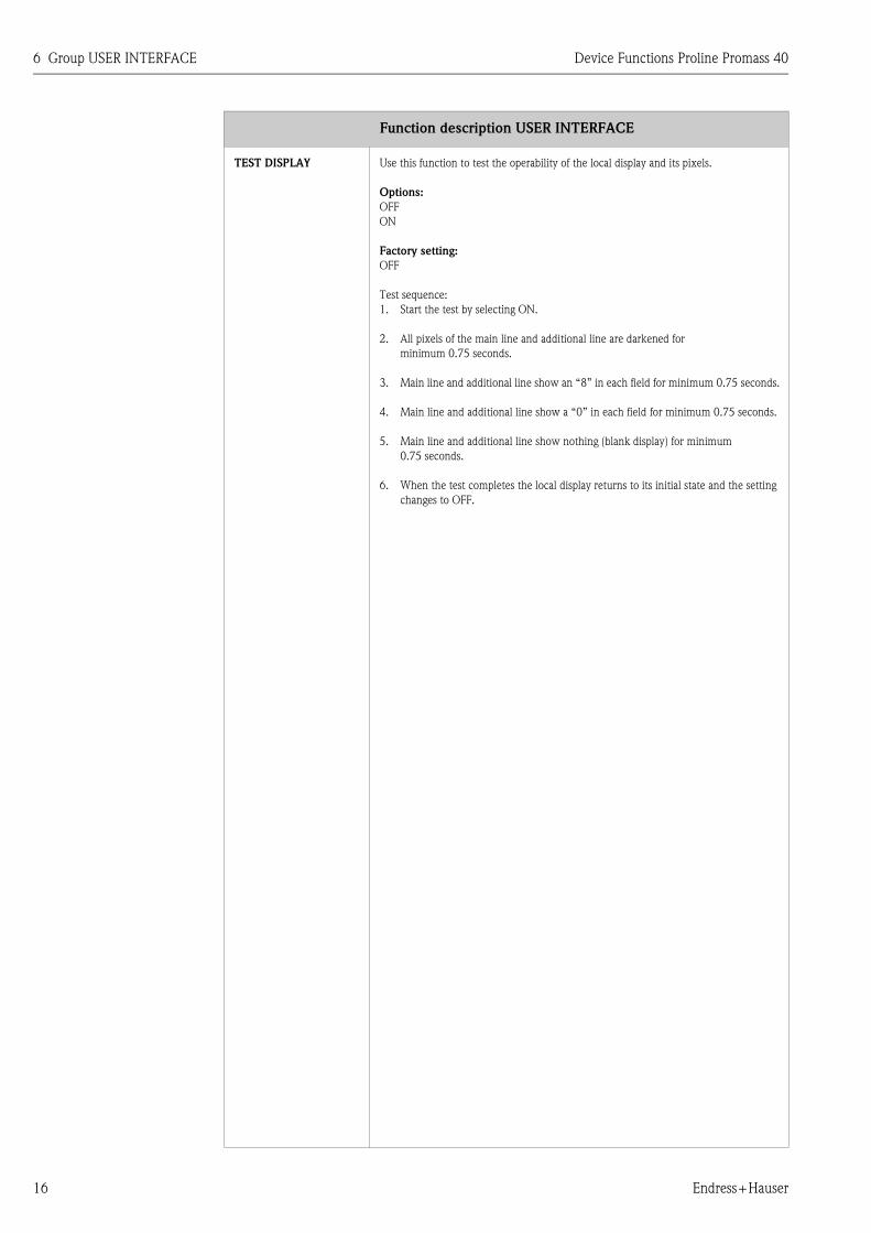
TEST DISPLAY Use this function to test the operability of the local display and its pixels.
Options:
OFF
ON
Factory setting:
OFF
Test sequence:
1. Start the test by selecting ON.
2. All pixels of the main line and additional line are darkened for
minimum 0.75 seconds.
3. Main line and additional line show an “8” in each field for minimum 0.75 seconds.
4. Main line and additional line show a “0” in each field for minimum 0.75 seconds.
5. Main line and additional line show nothing (blank display) for minimum
0.75 seconds.
6. When the test completes the local display returns to its initial state and the setting
changes to OFF.
Function description USER INTERFACE

Device Functions Proline Promass 40 7 Group TOTALIZER
Endress+Hauser 17
7 Group TOTALIZER
Function description TOTALIZER
SUM Use this function to view the total for the totalizer measured variable accumulated
since measuring commenced. The value can be positive or negative.
Display shows:
max. 7-digit floating-point number, including sign and unit (e.g. 15467.04 kg)
! Note!
• The totalizer response to faults is defined in the FAILSAFE MODE TOTALIZER
function (see Page 18).
• The unit of the totalizer depends on the selections in the MASS/VOL./CORR.VOL.
function and in the SYSTEM UNITS group.
OVERFLOW Use this function to view the overflow for the totalizer accumulated since measuring
commenced.
Total flow quantity is represented by a floating decimal point number consisting of max.
7 digits. You can use this function to view higher numerical values (>9,999,999) as
overflows. The effective quantity is thus the total of OVERFLOW plus the value
returned by the SUM function.
Example:
Reading for 2 overflows: 2 E7 kg (= 20,000,000 kg)
The value returned by the SUM function = 196,845.7 kg
Effective total quantity = 20,196,845.7 kg
Display shows:
Integer with exponent, including sign and unit, e.g. 2 E7 kg
RESET TOTALIZER Use this function to reset the sum and the overflow of the totalizer to zero.
Options:
NO - YES
Factory setting:
NO
! Note!
If the device has a status input and is appropriately configured, a reset for the totalizer
can also be triggered by a pulse.
TOTALIZER MODE Use this function to define how the flow components are to be totalized.
Options:
BALANCE
Positive and negative flow components. The positive and negative flow components are
balanced. In other words, net flow in the flow direction is registered.
FORWARD
Only positive flow components are totalized.
REVERSE
Only negative flow components are totalized.
Factory setting:
Totalizer 1 = BALANCE
Totalizer 2 = FORWARD

8 Group HANDLING TOTALIZER Device Functions Proline Promass 40
18 Endress+Hauser
8 Group HANDLING TOTALIZER
Function description HANDLING TOTALIZER
ERROR CATEGORY Use this function to define the totalizer response to fault.
Options:
STOP
The totalizer is paused until the fault is rectified.
ACTUAL VALUE
The totalizer continues to count based on the current flow measured value.
The fault is ignored.
HOLD VALUE
The totalizer continues to count the flow based on the last valid flow value (before the
fault occurred).
Factory setting:
STOP

Device Functions Proline Promass 40 9 Group CURRENT OUTPUT
Endress+Hauser 19
9 Group CURRENT OUTPUT
Function description CURRENT OUTPUT
The current output is automatically assigned to mass, volume or corrected volume measurement, depending on the
selection in the MASS/VOL./CORR.VOL. function (see Page 7).
CURRENT SPAN Use this function to define the current span. The selection specifies the operational
range and the lower and upper signal on alarm. For the current output 1 the option
HART can be defined additionally.
Options:
4–20 mA HART
4–20 mA HART NAMUR
4–20 mA HART US
4–20 mA (25 mA) HART
Factory setting:
4–20 mA HART NAMUR
! Note!
When switching the hardware from an active (factory setting) to a passive output signal
select a current span of 4–20 mA (please refer to the Operating Instructions Proline
Promass 40, BA 061D/06/en).
Current span, operational range and signal on alarm level
a = Current span
1 = Operational range (measuring information)
2 = Lower signal on alarm level
3 = Upper signal on alarm level
! Note!
• If the measured value exceeds the measuring range (as defined in the function
VALUE 20 mA) a notice message is generated (#351 current span).
• In case of a fault the behavior of the current output is according to the selected
option in the function ERROR CATEGORY. Change the error category in the func-
tion ASSIGN SYSTEM ERROR to generate a fault message instead of a notice mes-
sage.
12 3
I [mA]
a 1 2 3
4-20 mA HART 4 - 20.5 mA 2 22
4-20 mA HART NAMUR 3.8 - 20.5 mA 3.5 22.6
4-20 mA HART US 3.9 - 20.8 mA 3.75 22.6
4-20 mA (25 mA) HART 4 - 24 mA 2 25 A00
0323
2

9 Group CURRENT OUTPUT Device Functions Proline Promass 40
20 Endress+Hauser
VALUE 20 mA Use this function to assign a flow value to the 20 mA current.
In the SYMMETRY measuring mode (see Page 44), the value assigned in this way
applies to both flow directions; in the STANDARD measuring mode it applies only to
positive flow (forward flow).
User input:
5-digit floating-point number (with sign for the MASS FLOW, VOLUME FLOW, COR-
RECTED VOLUME FLOW measured variables)
Factory setting:
depends on nominal diameter and country (see Page 52).
! Note!
The appropriate unit is taken from the corresponding UNIT function in the group
SYSTEM UNITS (see Page 9).
TIME CONSTANT Use this function to enter a time constant defining how the current output signal reacts
to severely fluctuating measured variables, either very quickly (enter a low time con-
stant) or with damping (enter a high time constant).
User input:
Fixed-point number: 0.01...100.00 s
Factory setting:
1.00 s
ERROR CATEGORY For reasons of safety it is advisable to ensure that the current output assumes a
predefined state in the event of a fault. The setting you select here affects only the
current output. It has no effect on other outputs and the display (e.g. totalizers).
Options:
MINIMUM CURRENT
The current output adopts the value of the lower signal on alarm level (as defined in the
function CURRENT SPAN).
MAXIMUM CURRENT
The current output adopts the value of the upper signal on alarm level (as defined in the
function CURRENT SPAN).
HOLD VALUE (not recommended)
Measuring value output is based on the last measuring value saved before the error
occurred .
ACTUAL VALUE
Measured value output on the basis of the current flow measurement.
The fault is ignored.
Factory setting:
MINIMUM CURRENT
ACTUAL CURRENT Use this function to view the computed value of the output current.
Display shows:
0.00...25.00 mA
Function description CURRENT OUTPUT

Device Functions Proline Promass 40 9 Group CURRENT OUTPUT
Endress+Hauser 21
SIMULATION CURR Use this function to activate simulation of the current output.
Options:
ON
OFF
Factory setting:
OFF
! Note!
The “SIMULATION CURRENT OUTPUT” message indicates that simulation is active.
The measuring device continues to measure while simulation is in progress, i.e. the
actual measured values are output correctly via the other outputs.
" Caution!
The setting is not saved if the power supply fails.
VALUE SIMULATION
CURRENT ! Note!
This function is not available unless the SIMULATION CURR function is active (= ON).
Use this function to define a selectable value (e.g. 12 mA) to be output at the current
output. This value is used to test downstream devices and the flowmeter itself.
User input:
Floating-point number: 0.00...25.00 mA
Factory setting:
0.00 mA
" Caution!
The setting is not saved if the power supply fails.
Function description CURRENT OUTPUT

10 Group PULSE/FREQUENCY OUTPUT Device Functions Proline Promass 40
22 Endress+Hauser
10 Group PULSE/FREQUENCY OUTPUT
Function description PULSE/FREQUENCY OUTPUT
The pulse/frequency output is automatically assigned to mass, volume or corrected volume measurement, depending
on the selection in the function MASS/VOL./CORR.VOL. (see Page 7).
OPERATION MODE Use this function to configure the output as a pulse or frequency output. The functions
available in this function group vary, depending on which option you select here.
Options:
PULSE
FREQUENCY
Factory setting:
PULSE
END VALUE FREQ.! Note!
This function is not available unless the FREQUENCY setting was selected in the
OPERATION MODE function.
Use this function to define a full scale frequency for the frequency output. You define
the associated measured value of the measuring range in the VALUE F HIGH function
described on Page 23.
User input:
5-digit fixed-point number: 2...1000 Hz
Factory setting:
1000 Hz
Example:
• VALUE F HIGH = 1000 kg/h, full scale frequency = 1000 Hz: i.e. a frequency of
1000 Hz is output at a flow of 1000 kg/h.
• VALUE F HIGH = 3600 kg/h, full scale frequency = 1000 Hz: i.e. a frequency of
1000 Hz is output at a flow of 3600 kg/h.
! Note!
In the FREQUENCY operating mode the output signal is symmetrical (on/off ratio =
1:1). At low frequencies the pulse duration is limited to a maximum of 10 seconds, i.e.
the on/off ratio is no longer symmetrical.

Device Functions Proline Promass 40 10 Group PULSE/FREQUENCY OUTPUT
Endress+Hauser 23
VALUE F HIGH! Note!
This function is not available unless the FREQUENCY setting was selected in the
OPERATION MODE function.
Use this function to assign a flow value to the full scale frequency.
Positive and negative values are permissible. You define a measuring range by defining
the VALUE F HIGH.
User input:
5-digit floating-point number
Factory setting:
depends on nominal diameter
m = VALUE F HIGH, n = Measuring range, Q = Flow (forward/backward)
! Note!
The appropriate unit is taken from the corresponding UNIT function in the group
SYSTEM UNITS (see Page 9).
Function description PULSE/FREQUENCY OUTPUT
125
Freq. [%]
Q
100
0
➀
➁
A00012
24

10 Group PULSE/FREQUENCY OUTPUT Device Functions Proline Promass 40
24 Endress+Hauser
OUTPUT SIGNAL! Note!
This function is not available unless the FREQUENCY setting was selected in the
OPERATION MODE function.
Use this function to select the polarity of the frequency signal.
Options:
PASSIVE – POSITIVE, PASSIVE – NEGATIVE
Factory setting:
PASSIVE - POSITIVE
Explanation
• PASSIVE = power is supplied to the frequency output by means of an external power
supply.
Configuring the output signal level (POSITIVE or NEGATIVE) determines the quiescent
behavior (at zero flow) of the frequency output.
The internal transistor is activated as follows:
• If POSITIVE is selected, the internal transistor is activated with a positive signal
level.
• If NEGATIVE is selected, the internal transistor is activated with a negative signal
level (0 V).
!Note!
With the passive output configuration, the output signal levels of the frequency output
depend on the external circuit (see examples).
Example for passive output circuit (PASSIVE)
If PASSIVE is selected, the frequency output is configured as an open collector.
A0001225
m = Open collector
n = External power supply
!Note!
For continuous currents up to 25 mA (Imax = 250 mA / 20 ms).
Example for output configuration PASSIVE-POSITIVE:
Output configuration with an external pull-up resistance.
In the quiescent state (at zero flow), the output signal level at the terminals is 0 V.
F06-xxxxxxxx-04-xx-xx-xx-000
m = Open collector
n = Pull-up resistance
o = Transistor activation in “POSITIVE” quiescent state (at zero flow)
p = Output signal level in quiescent state (at zero flow)
In the operating status (flow present), the output signal level changes from 0 V to a
positive voltage level.
A0001967
(Continued on next page)
Function description PULSE/FREQUENCY OUTPUT
1 5 8 37+
-
=U = 30 V DC
max
m
n
U = 30 V DCmax
+
U (V)
t
U (V)
to p
mn
U (V)
t

Device Functions Proline Promass 40 10 Group PULSE/FREQUENCY OUTPUT
Endress+Hauser 25
OUTPUT SIGNAL
(continued)
Example for output configuration PASSIVE-POSITIVE:
Output configuration with an external pull-down resistance.
In the quiescent state (at zero flow), a positive voltage level is measured via the pull-
down resistance.
F06-xxxxxxxx-04-xx-xx-xx-001
m = Open collector
n = Pull-down resistance
o = Transistor activation in “POSITIVE” quiescent state (at zero flow)
p = Output signal level in quiescent state (at zero flow)
In the operating status (flow present), the output signal level changes from a positive
voltage level to 0 V.
A0001972
Example for output configuration PASSIVE-NEGATIVE:
Output configuration with an external pull-up resistance.
In the quiescent state (at zero flow), the output signal level at the terminals is at a
positive voltage level.
F06-xxxxxxxx-04-xx-xx-xx-002
m = Open collector
n = Pull-up resistance
o = Transistor activation in “NEGATIVE” quiescent state (at zero flow)
p = Output signal level in quiescent state (at zero flow)
In the operating status (flow present), the output signal level changes from a positive
voltage level to 0 V.
A0001972
Function description PULSE/FREQUENCY OUTPUT
U = 30 V DCmax
o p
+
U (V)
t
U (V)
t
m
n
U (V)
t
U = 30 V DCmax
+
U (V)
t
U (V)
to p
mn
U (V)
t

10 Group PULSE/FREQUENCY OUTPUT Device Functions Proline Promass 40
26 Endress+Hauser
TIME CONSTANT! Note!
This function is not available unless the FREQUENCY setting was selected in the
OPERATION MODE function.
Use this function to enter a time constant defining how the frequency output signal
reacts to severely fluctuating measured variables, either very quickly (enter a low time
constant) or with damping (enter a high time constant).
User input:
Floating-point number 0.00...100.00 s
Factory setting:
0.00 s
ERROR CATEGORY! Note!
This function is not available unless the FREQUENCY setting was selected in the
OPERATION MODE function.
For safety reasons it is advisable to ensure that the frequency output assumes a pre-
defined state in the event of a fault. Use this function to define this state. The setting
you select here affects only the frequency output. It has no effect on other outputs and
the display (e.g. totalizer).
Options:
FALLBACK VALUE
Output is 0 Hz.
FAILSAFE LEVEL
Output is the frequency specified in the FAILSAFE VALUE function.
HOLD VALUE (not recommended)
Measuring value output is based on the last measuring value saved before the error
occurred .
ACTUAL VALUE
Measured value output on the basis of the current flow measurement. The fault is
ignored.
Factory setting:
FALLBACK VALUE
FAILSAFE VALUE! Note!
This function is not available unless FREQUENCY was selected in the OPERATION
MODE function and FAILSAFE LEVEL was selected in the ERROR CATEGORY func-
tion.
Use this function to define frequency that the measuring device outputs in the event of
a fault.
User input:
max. 4-digit number: 0...1250 Hz
Factory setting:
1250 Hz
Function description PULSE/FREQUENCY OUTPUT

Device Functions Proline Promass 40 10 Group PULSE/FREQUENCY OUTPUT
Endress+Hauser 27
ACTUAL FREQUENCY! Note!
This function is not available unless the FREQUENCY setting was selected in the
OPERATION MODE function.
Use this function to view the computed value of the output frequency.
Display shows:
0...1250 Hz
SIMULATION FRE-
QUENCY ! Note!
This function is not available unless the FREQUENCY setting was selected in the
OPERATION MODE function.
Use this function to activate simulation of the frequency output.
Options:
OFF
ON
Factory setting:
OFF
! Note!
• The “SIMULATION FREQUENCY OUTPUT” message indicates that simulation is
active.
• The measuring device continues to measure while simulation is in progress, i.e. the
actual measured values are output correctly via the other outputs.
" Caution!
The setting is not saved if the power supply fails.
VALUE SIMULATION
FREQUENCY ! Note!
This function is not available unless FREQUENCY was selected in the OPERATION
MODE function and the VALUE SIMULATION FREQUENCY function is active
(= ON).
Use this function to define a selectable frequency value (e.g. 500 Hz) to be output at
the frequency output. This value is used to test downstream devices and the flowmeter
itself.
User input:
0...1250 Hz
Factory setting:
0 Hz
" Caution!
The setting is not saved if the power supply fails.
Function description PULSE/FREQUENCY OUTPUT

10 Group PULSE/FREQUENCY OUTPUT Device Functions Proline Promass 40
28 Endress+Hauser
PULSE VALUE! Note!
This function is not available unless the PULSE setting was selected in the OPERATION
MODE function.
Use this function to define the flow at which a pulse is triggered. These pulses can be
totaled by an external totalizer, and the total flow quantity since measuring started can
be registered in this way.
User input:
5-digit floating-point number
Factory setting:
depends on nominal diameter and country (see Page 52).
! Note!
The appropriate unit is taken from the corresponding UNIT function in the group
SYSTEM UNITS (see Page 9).
PULSE WIDTH! Note!
This function is not available unless the PULSE setting was selected in the OPERATION
MODE function.
Use this function to enter the pulse width of the output pulses.
User input:
0.5...2000 ms
Factory setting:
100 ms
Pulse output is always with the pulse width (B) entered in this function. The intervals
(P) between the individual pulses are automatically configured. However, they must at
least correspond to the pulse width (B = P).
B = Pulse width entered (the illustration applies to positive pulses)
P= Intervals between the individual pulses
! Note!
When entering the pulse width, select a value that can still be processed by an external
totalizer (e.g. mechanical totalizer, PLC, etc.).
" Caution!
If the pulse number or frequency resulting from the pulse value entered (see function
PULSE VALUE on Page 28), and from the current flow is too large to maintain the
pulse width selected (interval P is smaller than the pulse width B entered), a system
error message (pulse memory) is generated after buffering/balancing time.
Function description PULSE/FREQUENCY OUTPUT
B=P
B
PP
B
B< P
A0001233

Device Functions Proline Promass 40 10 Group PULSE/FREQUENCY OUTPUT
Endress+Hauser 29
OUTPUT SIGNAL! Note!
This function is not available unless the PULSE setting was selected in the OPERATION
MODE function.
Use this function to configure the output in such a way that it matches an external
totalizer, for example. The direction of the pulses can be selected here, if this feature is
supported by the application.
Options:
PASSIVE - POSITIVE, PASSIVE - NEGATIVE
Factory setting: PASSIVE - POSITIVE
Explanation
• PASSIVE = power is supplied to the pulse output by means of an external power
supply.
Configuring the output signal level (POSITIVE or NEGATIVE) determines the quiescent
behavior (at zero flow) of the pulse output.
The internal transistor is activated as follows:
• If POSITIVE is selected, the internal transistor is activated with a positive signal
level.
• If NEGATIVE is selected, the internal transistor is activated with a negative signal
level (0 V).
!Note!
With the passive output configuration, the output signal levels of the pulse output
depend on the external circuit (see examples).
Example for passive output circuit (PASSIVE)
If PASSIVE is selected, the pulse output is configured as an open collector.
A0001225
m = Open collector, n = External power supply
!Note!
For continuous currents up to 25 mA (Imax = 250 mA / 20 ms).
Example for output configuration PASSIVE-POSITIVE:
Output configuration with an external pull-up resistance. In the quiescent state (at zero
flow), the output signal level at the terminals is 0 V.
F06-xxxxxxxx-04-xx-xx-xx-000
m = Open collector
n = Pull-up resistance
o = Transistor activation in “POSITIVE” quiescent state (at zero flow)
p = Output signal level in quiescent state (at zero flow)
In the operating status (flow present), the output signal level changes from 0 V to a
positive voltage level.
A0001967
(Continued on next page)
Function description PULSE/FREQUENCY OUTPUT
1 5 8 37+
-
=U = 30 V DC
max
m
n
U = 30 V DCmax
+
U (V)
t
U (V)
to p
mn
U (V)
t

10 Group PULSE/FREQUENCY OUTPUT Device Functions Proline Promass 40
30 Endress+Hauser
OUTPUT SIGNAL
(continued)
Example for output configuration PASSIVE-POSITIVE:
Output configuration with an external pull-down resistance.
In the quiescent state (at zero flow), a positive voltage level is measured via the pull-
down resistance.
F06-xxxxxxxx-04-xx-xx-xx-001
m = Open collector
n = Pull-down resistance
o = Transistor activation in “POSITIVE” quiescent state (at zero flow)
p = Output signal level in quiescent state (at zero flow)
In the operating status (flow present), the output signal level changes from a positive
voltage level to 0 V.
A0001972
Example for output configuration PASSIVE-NEGATIVE:
Output configuration with an external pull-up resistance.
In the quiescent state (at zero flow), the output signal level at the terminals is at a posi-
tive voltage level.
F06-xxxxxxxx-04-xx-xx-xx-002
m = Open collector
n = Pull-up resistance
o = Transistor activation in “NEGATIVE” quiescent state (at zero flow)
p = Output signal level in quiescent state (at zero flow)
In the operating status (flow present), the output signal level changes from a positive
voltage level to 0 V.
A0001972
Function description PULSE/FREQUENCY OUTPUT
U = 30 V DCmax
o p
+
U (V)
t
U (V)
t
m
n
U (V)
t
U = 30 V DCmax
+
U (V)
t
U (V)
to p
mn
U (V)
t

Device Functions Proline Promass 40 10 Group PULSE/FREQUENCY OUTPUT
Endress+Hauser 31
ERROR CATEGORY! Note!
This function is not available unless the PULSE setting was selected in the OPERATION
MODE function.
For safety reasons it is advisable to ensure that the pulse output assumes a predefined
state in the event of a fault. Use this function to define this state. The setting you select
here affects only the pulse output. It has no effect on other outputs and the display
(e.g. totalizer).
Options:
FALLBACK VALUE
Output is 0 pulse.
HOLD VALUE (not recommended)
Measuring value output is based on the last measuring value saved before the error
occurred .
ACTUAL VALUE
Measured value output on the basis of the current flow measurement. The fault is
ignored.
Factory setting:
FALLBACK VALUE
SIMULATION PULSE! Note!
This function is not available unless the PULSE setting was selected in the OPERATION
MODE function.
Use this function to activate simulation of the pulse output.
Options:
OFF
COUNTDOWN
The pulses specified in the VALUE SIMULATION PULSE function are output.
CONTINUOUSLY
Pulses are continuously output with the pulse width specified in the PULSE WIDTH
function.
! Note!
Simulation is started by selecting CONTINUOUSLY. The simulation can be switched
off again via the SIMULATION PULSE function.
Factory setting:
OFF
! Note!
• The notice message #631 “SIM. PULSE” indicates that simulation is active.
• The on/off ratio is 1:1 for both types of simulation.
• The measuring device continues to measure while simulation is in progress, i.e. the
actual measured values are output correctly via the other outputs.
" Caution!
The setting is not saved if the power supply fails.
Function description PULSE/FREQUENCY OUTPUT

10 Group PULSE/FREQUENCY OUTPUT Device Functions Proline Promass 40
32 Endress+Hauser
VALUE SIMULATION
PULSE ! Note!
This function is not available unless the COUNTDOWN option was selected in the
SIMULATION PULSE function.
Use this function to specify the number of pulses (e.g. 50) which are output during the
simulation. This value is used to test downstream devices and the flowmeter itself. The
pulses are output with the pulse width specified in the PULSE WIDTH function. The
on/off ratio is 1:1.
Simulation is started once the specified value is confirmed. The display remains at 0 if
the specified pulses have been output.
User input:
0...10 000
Factory setting:
0
! Note!
Simulation is started by confirming the simulation value. The simulation can be
switched off again via the SIMULATION PULSE function.
" Caution!
The setting is not saved if the power supply fails.
Function description PULSE/FREQUENCY OUTPUT

Device Functions Proline Promass 40 11 Group STATUS OUTPUT
Endress+Hauser 33
11 Group STATUS OUTPUT
Function description STATUS OUTPUT
This group is not available unless the measuring device is fitted with a status output.
ASSIGN STATUS Use this function to assign a switching function to the status output.
Options:
OFF
ON (operation)
FAULT MESSAGE
NOTICE MESSAGE
FAULT MESSAGE or NOTICE MESSAGE
EMPTY PIPE DETECTION (only if function is active)
FLOW DIRECTION
LIMIT MASS FLOW (if the instrument works as mass flowmeter)
LIMIT VOLUME FLOW (if the instrument works as volume flowmeter)
Factory setting:
FAULT MESSAGE
! Note!
• The behavior of the status output is of the quiescent-current type, in other words the
output is closed (status output conductive) when normal, error-free measuring is in
progress.
• Please read and comply with the information on the switching characteristics of the
status output (see Page 35, 36).
• If you select OFF, the only function shown in this function group is this function, in
other words ASSIGN STATUS.
ON-VALUE! Note!
This function is not available unless LIMIT MASS FLOW, LIMIT VOLUME FLOW or
FLOW DIRECTION was selected in the ASSIGN STATUS function.
Use this function to assign a value to the switch-on point (status output conductive).
The value can be greater or less than the switch-off point. Positive and negative values
are permissible.
User input:
5-digit floating-point number
Factory setting:
0 [kg/h] or 0 [m3/h]
OFF-VALUE! Note!
This function is not available unless LIMIT MASS FLOW or LIMIT VOLUME FLOW
was selected in the ASSIGN STATUS function.
Use this function to assign a value to the switch-off point (status output not conduc-
tive). The value can be greater or less than the switch-on point. Positive and negative
values are permissible.
User input:
5-digit floating-point number
Factory setting:
0 [kg/h] or 0 [m3/h]

11 Group STATUS OUTPUT Device Functions Proline Promass 40
34 Endress+Hauser
TIME CONSTANT Use this function to enter a time constant defining how the status output reacts to
severely fluctuating measured variables, either very quickly (enter a low time constant)
or with damping (enter a high time constant).
The purpose of damping, therefore, is to prevent the status output changing state con-
tinuously in response to fluctuations in flow.
User input:
5-digit floating-point number: 0.00...100.00 s
Factory setting:
0.00 s
ACTUAL STATUS OUT-
PUT
Use this function to check the current status of the status output.
Display shows:
NOT CONDUCTIVE
CONDUCTIVE
SIMULATION SWITCH
POINT
Use this function to activate simulation of the status output.
Options:
OFF
ON
Factory setting:
OFF
! Note!
• The “SIMULATION STATUS OUTPUT” message indicates that simulation is active.
• The measuring device continues to measure while simulation is in progress, i.e. the
actual measured values are output correctly via the other outputs.
" Caution!
The setting is not saved if the power supply fails.
VALUE SIMULATION
SWITCH POINT ! Note!
This function is not available unless the SIMULATION SWITCH POINT function is
active (= ON).
Use this function to define the switching response of the status output during the simu-
lation. This value is used to test downstream devices and the flowmeter itself.
User input:
NOT CONDUCTIVE
CONDUCTIVE
Factory setting:
NOT CONDUCTIVE
" Caution!
The setting is not saved if the power supply fails.
Function description STATUS OUTPUT

Device Functions Proline Promass 40 11 Group STATUS OUTPUT
Endress+Hauser 35
11.1 Information on the response of the status output
General
If you have configured the status output for “LIMIT” or “FLOW DIRECTION”, you can define the requisite switching
points in the ON-VALUE and OFF-VALUE functions. When the measured variable in question reaches one of these pre-
defined values, the status output signal switches as shown in the illustrations below.
Status output configured for direction of flow
The value you entered in the ON-VALUE function defines the switching points for the positive and negative directions of
flow.
If, for example, the switching point you define is = 1 kg/h, the status output is not conductive at –1 kg/h and is conductive
at +1 kg/h. Set the switching point to 0 if your process calls for direct switchover (no switching hysteresis). If low flow cut
off is used, it is advisable to set hysteresis to a value greater than or equal to the low flow cut off rate.
Switch-off / switch-on point
a = Status output conductive
b = Status output not conductive
Status output configured for limit value
The status output signal switches as soon as the measured variable falls below or exceeds a defined switching point.
Application: Monitoring flow or process-related boundary conditions.
Measured variable
A = Maximum safety → m OFF-VALUE > n ON-VALUE
B = Minimum safety → m OFF-VALUE < n ON-VALUE
C = Minimum safety → m OFF-VALUE = n ON-VALUE (this configuration must be avoided)
o = Status output switched off (not conductive)
A000
1236
-1 0 +1 a
b
-Q Q
A000
1235
t
o o
nnm
o
nm
A B C
m

11 Group STATUS OUTPUT Device Functions Proline Promass 40
36 Endress+Hauser
11.2 Switching response of the status output
Function State Open Collector (Transistor)
ON (operation) System in measuring mode conductive
System not in measuring mode
(power supply failure)
not
conductive
Fault message System OK conductive
(System or process error)
Fault ➝ Failsafe mode of outputs,
inputs and totalizer
not
conductive
Notice message System OK conductive
(System or process error)
Fault ➝ Continuation of
measuring
not
conductive
Fault message
or
Notice message
System OK conductive
(System or process error)
Fault ➝ Failsafe mode or
Notice ➝ Continuation of
measuring
not
conductive
Empty pipe detec-
tion (EPD)
Fluid density above EPD response
level, e.g. with full measuring
tube
conductive
Fluid density below EPD response
level, e.g. with a partially filled or
an empty measuring tube
not
conductive
Flow direction forward conductive
reversenot
conductive
Limit value
Mass flow
Volume flow
Limit value not overshot or
undershotconductive
Limit value overshot or undershotnot
conductive
XXX.XXX.XX
XXX.XXX.XX
XXX.XXX.XX
XXX.XXX.XX
XXX.XXX.XX
XXX.XXX.XX
XXX.XXX.XX
XXX.XXX.XX

Device Functions Proline Promass 40 12 Group STATUS INPUT
Endress+Hauser 37
12 Group STATUS INPUT
Function description STATUS INPUT
This group is not available unless the measuring device is fitted with a status input I/O module.
ASSIGN STATUS INPUT Use this function to assign a switching function to the status input.
Options:
OFF
RESET TOTALIZER
POSITIVE ZERO RETURN
ZEROPOINT ADJUSTMENT
Factory setting:
OFF
! Note!
Positive zero return is active as long as the active level is available at the status input
(continuous signal). All other assignments react to a change in level (pulse) at the status
input.
ACTIVE LEVEL Use this function to define whether the assigned function (see ASSIGN STATUS INPUT
function) is released when the signal level is present (HIGH) or not present (LOW).
Options:
HIGH
LOW
Factory setting:
HIGH
MINIMUM PULSE
WIDTH
Use this function to define a minimum width which the input pulse must achieve in
order to trigger the defined switching function.
User input:
20...100 ms
Factory setting:
50 ms
SIMULATION STATUS
INPUT
Use this function to activate simulation of the status input, in other words to trigger the
function assigned to the status input (see the ASSIGN STATUS INPUT function on
Page 37).
Options:
OFF
ON
Factory setting:
OFF
! Note!
The “SIMULATION STATUS INPUT” message indicates that simulation is active.
" Caution!
The setting is not saved if the power supply fails.

12 Group STATUS INPUT Device Functions Proline Promass 40
38 Endress+Hauser
VALUE SIMULATION
STATUS INPUT ! Note!
This function is not available unless the SIMULATION STATUS INPUT function is
active (= ON).
Use this function to select the level to be assumed at the status input during the simula-
tion.
Options:
HIGH
LOW
Factory setting:
LOW
" Caution!
The setting is not saved if the power supply fails.
Function description STATUS INPUT

Device Functions Proline Promass 40 13 Group COMMUNICATION
Endress+Hauser 39
13 Group COMMUNICATION
Function description COMMUNICATION
TAG NAME Use this function to enter a tag name for the measuring device.
User input:
max. 8-character text, permissible: A-Z, 0-9, +, –, punctuation marks
Factory setting:
“_ _ _ _ _ _ _ _” (without text)
TAG DESCRIPTION Use this function to enter a tag description for the measuring device.
User input:
max. 16-character text, permissible: A-Z, 0-9, +, –, punctuation marks
Factory setting:
“_ _ _ _ _ _ _ _ _ _ _ _ _ _ _ _” (without text)
BUS ADDRESS Use this function to define the address for the exchange of data with the
HART protocol.
User input:
0...15
Factory setting:
0
! Note!
Addresses 1...15: a constant 4 mA current is applied.
WRITE PROTECTION Use this function to check whether the measuring device can be write accessed.
Display shows:
OFF = Data exchange is possible
ON = Data exchange disabled (an activation of the write protection is at present not
available)
Factory setting:
OFF
MANUFACTURER ID Use this function to view the manufacturer ID in decimal numerical format.
Display shows:
17 (≅ 11 hex) for Endress+Hauser
DEVICE ID Use this function to view the device ID in hexadecimal numerical format.
Display shows:
53 (≅ 83 dec) for Promass 40

14 Group PROCESS PARAMETER Device Functions Proline Promass 40
40 Endress+Hauser
14 Group PROCESS PARAMETER
Function description PROCESS PARAMETER
ON VALUE LOW FLOW
CUT OFF
Use this function to assign the on-value for the low flow cut off.
Low flow cut off is active if the setting is a value not equal to 0. The sign of the flow
value is highlighted on the display to indicate that low flow cut off is active.
User input:
5-digit floating-point number
Factory setting:
depends on nominal diameter
! Note!
The appropriate unit is taken from the corresponding UNIT function in the group
SYSTEM UNITS (see Page 9).
OFF VALUE LOW
FLOW CUT OFF
Use this function to enter the switch-off point for low flow cut off.
Enter the switch-off point as a positive hysteresis value from the switch-on point.
User input:
Integer 0...100%
Factory setting:
50%
Example:
Q = Flow [volume/time]
t = Time
a = ON VALUE = 200 g/h
b = OFF VALUE = 10%
c = Low flow cut off is active
1 = Low flow cut off is switched on at 200 g/h
2 = Low flow cut off is switched off at 220 g/h
H = Hysteresis
1
c c
Q
t
1
2b
a
2
H
A0
0012
45

Device Functions Proline Promass 40 14 Group PROCESS PARAMETER
Endress+Hauser 41
EMPTY PIPE DETEC-
TION (EPD)
Use this function to activate the empty pipe detection (EPD). With empty measuring
tubes the density of the fluid falls below a specified value (see EPD VALUE LOW func-
tion).
Options:
OFF
ON
Factory setting:
ON
" Caution!
• Select a correspondingly low EPD response value so that the difference to the effec-
tive density of the fluid is sufficiently large enough. This ensures that totally empty
measuring tubes and not partially filled ones are detected.
• For gas measurement we strongly recommend to switch off empty pipe detection.
EPD VALUE LOW! Note!
This function is not available unless the ON selection was selected in the EPD function.
Use this function to set a lower threshold for the fluid density value, in order to detect
possible problems in the process indicated by too low density.
User input:
5-digit floating-point number
Factory setting:
0.2000 kg/l
EPD RESPONSETIME Use this function to enter the time span for which the criteria for an empty pipe have to
be satisfied without interruption before a notice message or fault message is generated.
User input:
Fixed-point number: 1.0...60.0 s
Factory setting:
1.0 s
Function description PROCESS PARAMETER
14 Group PROCESS PARAMETER Device Functions Proline Promass 40
42 Endress+Hauser
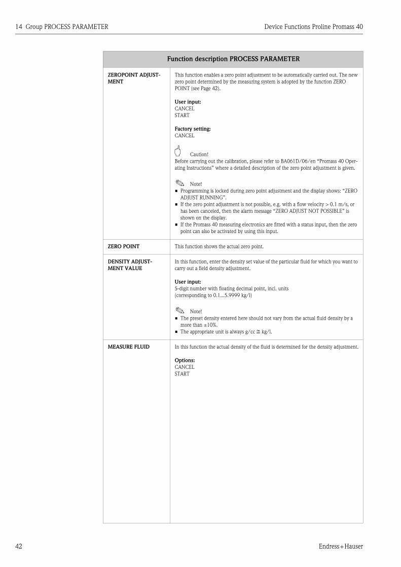
ZEROPOINT ADJUST-
MENT
This function enables a zero point adjustment to be automatically carried out. The new
zero point determined by the measuring system is adopted by the function ZERO
POINT (see Page 42).
User input:
CANCEL
START
Factory setting:
CANCEL
" Caution!
Before carrying out the calibration, please refer to BA061D/06/en “Promass 40 Oper-
ating Instructions” where a detailed description of the zero point adjustment is given.
! Note!
• Programming is locked during zero point adjustment and the display shows: “ZERO
ADJUST RUNNING”.
• If the zero point adjustment is not possible, e.g. with a flow velocity > 0.1 m/s, or
has been canceled, then the alarm message “ZERO ADJUST NOT POSSIBLE” is
shown on the display.
• If the Promass 40 measuring electronics are fitted with a status input, then the zero
point can also be activated by using this input.
ZERO POINT This function shows the actual zero point.
DENSITY ADJUST-
MENT VALUE
In this function, enter the density set value of the particular fluid for which you want to
carry out a field density adjustment.
User input:
5-digit number with floating decimal point, incl. units
(corresponding to 0.1...5.9999 kg/l)
! Note!
• The preset density entered here should not vary from the actual fluid density by a
more than ±10%.
• The appropriate unit is always g/cc ≅ kg/l.
MEASURE FLUID In this function the actual density of the fluid is determined for the density adjustment.
Options:
CANCEL
START
Function description PROCESS PARAMETER

Device Functions Proline Promass 40 14 Group PROCESS PARAMETER
Endress+Hauser 43
DENSITY ADJUST With this function a density adjustment can be carried out on site. The density set value
will thus be recalculated and stored. This ensures that the values dependent on density
calculations (e.g. volume flow) are as accurate as possible.
" Caution!
Before carrying out a density adjustment, please refer to BA061D/06/en “Promass 40
Operating Instructions” where a detailed description of the relevant procedure is given.
! Note!
The density adjustment is only required if the characteristics of the fluid are outside the
reference conditions under which the flowmeter has been calibrated at the factory.
User input:
CANCEL
DENSITY ADJUST
Factory setting:
CANCEL
RESTORE ORIGINAL With this function the original density coefficients determined at the factory are
restored.
User input:
NO
YES
Factory setting:
NO
Function description PROCESS PARAMETER

15 Group SYSTEM PARAMETER Device Functions Proline Promass 40
44 Endress+Hauser
15 Group SYSTEM PARAMETER
Function description SYSTEM PARAMETER
INSTALLATION DIREC-
TION SENSOR
Use this function to reverse the sign of the measured variable, if necessary.
! Note!
Ascertain the actual direction of fluid flow with reference to the direction indicated by
the arrow on the sensor (nameplate).
Options:
NORMAL (flow as indicated by the arrow)
INVERSE (flow opposite to direction indicated by the arrow)
Factory setting:
NORMAL
MEASURING MODE Use this function to define the measuring mode for all outputs and the internal total-
izer.
Options:
STANDARD
SYMMETRY
Factory setting:
STANDARD
The responses of the individual outputs and the internal totalizer in each of the measur-
ing modes are described in detail below:
Current and frequency output
STANDARD
The output signals of the current and frequency output are proportional to the mea-
sured variable.
The flow components outside the scaled measuring range (between Q = 0 ➀ and the
VALUE 20 mA or VALUE F HIGH ➁) are not taken into account for signal output, but
a message “CURRENT OUTPUT AT FULL SCALE VALUE” or “FREQUENCY OUTPUT
AT FULL SCALE VALUE” is issued.
Example for current output:
SYMMETRY
The output signals of the current and frequency output are independent of the direction
of flow (absolute amount of the measured variable).
The “VALUE 20 mA” or “VALUE F HIGH” ➂ (e.g. backflow) corresponds to the mir-
rored VALUE 20 mA or VALUE F HIGH ➁ (e.g. flow).
Example for current output:
Q
20
4
0
mA
➀ ➁
A00
0124
8
Q
20
0
mA
4
➂ ➀ ➁
A00012
49

Device Functions Proline Promass 40 15 Group SYSTEM PARAMETER
Endress+Hauser 45
MEASURING MODE
(continued)
Pulse output
STANDARD
Only positive flow components are totaled. Negative components are not taken into
account.
SYMMETRY
Positive and negative flow components are taken into account.
! Note!
The direction of flow can be output via the configurable status output.
Status output
! Note!
Only if in the ASSIGN STATUS function the LIMIT option is selected.
STANDARD
The status output signal switches at the defined switching points.
SYMMETRY
The status output signal switches at the defined switching points, irrespective of the
sign. In other words, if you define a switching point with a positive sign the status out-
put signal switches as soon as the value is reached in the negative direction (negative
sign) (see illustration).
Example for the SYMMETRY measuring mode:
Switch-on point: Q = 4
Switch-off point: Q = 10
➀ = Status output switched on (conductive)
➁ = Status output switched off (non-conductive)
Totalizer
STANDARD
Only positive flow components are totaled.
SYMMETRY
The positive and negative flow components are balanced. In other words, net flow in
the flow direction is registered.
Function description SYSTEM PARAMETER
0
- 4
- 10
4
10
Q
t
➀➀ ➁ ➀ ➁ ➀ A000
1247

15 Group SYSTEM PARAMETER Device Functions Proline Promass 40
46 Endress+Hauser
POSITIVE ZERO
RETURN
Use this function to interrupt evaluation of measured variables. This is necessary when
a piping system is being cleaned, for example.
The setting acts on all functions and outputs of the measuring device.
Options:
OFF
ON (signal output is set to zero flow value)
Factory setting:
OFF
FLOW DAMPING! Note!
System damping acts on all functions and outputs of the measuring device.
Using the interference blanking (= time constant for exponential filter) the sensitivity
of the flow measurement signal can be reduced with respect to transient flows and
interference peaks; e.g. with fluid containing solids or gas bubbles. Small negative com-
ponents are smoothed.
User input:
0.00...100 seconds (in 10 ms steps)
0.00 seconds = OFF
100 seconds = extremely high damping
Factory setting:
0.00 seconds
Function description SYSTEM PARAMETER

Device Functions Proline Promass 40 16 Group SENSOR DATA
Endress+Hauser 47
16 Group SENSOR DATA
Function description SENSOR DATA
All sensor data, including nominal diameter, calibration factor, and zero point, are set at the factory. All the sensor's
parameter settings are saved on the S-DAT memory chip.
K-FACTOR This function shows the current calibration factor for the sensor.
Factory setting:
depends on nominal diameter and calibration
ZERO POINT This function shows the current zero-point correction value for the sensor.
Factory setting:
depends on calibration
NOMINAL DIAMETER This function shows the nominal diameter for the sensor.
Factory setting:
depends on the size of the sensor
TEMPERATURE COEF-
FICIENT KM
This function shows the temperature coefficient KM.
DENSITY COEFF. C 0 This function shows the actual density coefficient C 0.
" Caution!
A density adjustment can alter the calibration value of this coefficient.
DENSITY COEFF. C 1 This function shows the actual density coefficient C 1.
" Caution!
A density adjustment can alter the calibration value of this coefficient.
DENSITY COEFF. C 2 This function shows the actual density coefficient C 2.
" Caution!
A density adjustment can alter the calibration value of this coefficient.
DENSITY COEFF. C 3 This function shows the actual density coefficient C 3.
" Caution!
A density adjustment can alter the calibration value of this coefficient.
MINIMAL
TEMPERATURE
MEASURED
This function shows the lowest fluid temperature measured.
MAXIMAL
TEMPERATURE
MEASURED
This function shows the highest fluid temperature measured.

17 Group SUPERVISION Device Functions Proline Promass 40
48 Endress+Hauser
17 Group SUPERVISION
Function description SUPERVISION
ACTUAL SYSTEM CON-
DITION
Use this function to check the current system status.
Display shows:
“SYSTEM OK” or the fault / notice message with the highest priority.
PREVIOUS SYSTEM
CONDITION
Use this function to view the 15 most recent fault and notice messages since measuring
last started.
Display shows:
The 15 most recent fault or notice messages.
ASSIGN SYSTEM
ERROR
Use this function to view all system messages and the associated error categories (fault
message or notice message). If you select a single system fault you can change its error
category.
Display shows:
List of system errors
! Note!
• Press “ENTER” twice to call the ERROR CATEGORY function.
• Use “ESC” or select CANCEL in the system error list to exit the function.
ERROR CATEGORY Use this function to define whether a system error triggers a notice message or a fault
message. If you select “FAULT MESSAGES”, all outputs respond to a fault in accor-
dance with their defined error-response patterns.
Options:
NOTICE MESSAGES (display only)
FAULT MESSAGES (outputs and display)
! Note!
• Press “ENTER” twice to call the ASSIGN SYSTEM ERROR function.
• Use “ESC” to exit the function.
ASSIGN PROCESS
ERROR
Use this function to view all process errors and the associated error categories (fault
message or notice message). If you select a single process error you can change its error
category.
Display shows:
List of process errors
! Note!
• Press “ENTER” twice to call the ERROR CATEGORY function.
• Use “ESC” or select CANCEL in the process error list to exit the function.

Device Functions Proline Promass 40 17 Group SUPERVISION
Endress+Hauser 49
ERROR CATEGORY Use this function to define whether a process error triggers a notice message or a fault
message. If you select “FAULT MESSAGES”, all outputs respond to a fault in accor-
dance with their defined error-response patterns.
Options:
NOTICE MESSAGES (display only)
FAULT MESSAGES (outputs and display)
! Note!
• Press “ENTER” twice to call the ASSIGN PROCESS ERROR function.
• Use “ESC” to exit the function.
ALARM DELAY Use this function to define a time span for which the criteria for an error have to be sat-
isfied without interruption before an error or notice message is generated.
Depending on the setting and the type of fault, this suppression acts on:
• Display
• Current output
• Frequency output
• Status output
User input:
0...100 s (in steps of one second)
Factory setting:
0 s
" Caution!
If this function is activated fault and notice messages are delayed by the time corre-
sponding to the setting before being forwarded to the higher-order controller (process
controller, etc.). It is therefore imperative to check in advance in order to make sure
whether a delay of this nature could affect the safety requirements of the process. If
fault and notice messages cannot be suppressed, a value of 0 seconds must be entered
here.
SYSTEM RESET Use this function to perform a reset of the measuring system.
Options:
NO
RESTART SYSTEM (restart without interrupting line supply)
Factory setting:
NO
OPERATION HOURS The hours of operation of the device appear on the display.
Display shows:
depends on the number of hours of operation elapsed:
Hours of operation < 10 hours → display format = 0:00:00 (hr:min:sec)
Hours of operation 10...10,000 hours → display format = 0000:00 (hr:min)
Hours of operation > 10,000 hours → display format = 000000 (hr)
Function description SUPERVISION

18 Group SIMULATION SYSTEM Device Functions Proline Promass 40
50 Endress+Hauser
18 Group SIMULATION SYSTEM
Function description SIMULATION SYSTEM
SIMULATION FAIL-
SAFE MODE
Use this function to set all inputs, outputs and totalizer to their defined fault response
modes, in order to check whether they respond correctly. During this time, the words
“SIMULATION FAILSAFE MODE” appear on the display.
Options:
OFF
ON
Factory setting:
OFF
" Caution!
• The measuring device cannot be used for measuring while this simulation is in
progress.
• The setting is not saved if the power supply fails.
SIMULATION
MEASURAND
Use this function to set all inputs, outputs and totalizer to their defined flow-response
modes, in order to check whether they respond correctly. During this time, the words
“SIMULATION MEASURAND” appear on the display.
Options:
OFF
MASS (if the instrument works as mass flowmeter)
VOLUME (if the instrument works as volume flowmeter)
CORRECTED VOLUME (if the instrument works as corrected volume flowmeter)
Factory setting:
OFF
" Caution!
• The measuring device cannot be used for measuring while this simulation is in
progress.
• The setting is not saved if the power supply fails.
VALUE SIMULATION
MEASURAND ! Note!
This function is not available unless the SIMULATION MEASURAND function is
active.
Use this function to define a selectable value (e.g. 12 kg/s). This value is used to test
downstream devices and the flowmeter itself.
User input:
5-digit floating-point number
Factory setting:
0
" Caution!
The setting is not saved if the power supply fails.

Device Functions Proline Promass 40 19 Group SENSOR VERSION
Endress+Hauser 51
19 Group SENSOR VERSION
20 Group AMPLIFIER VERSION
Function description SENSOR VERSION
SERIAL NUMBER Use this function to view the serial number of the sensor.
SENSOR TYPE Use this function to view the sensor type.
SOFTWARE REVISION
NUMBER S-DAT
Use this function to view the software revision number of the S-DAT.
Function description AMPLIFIER VERSION
DEVICE SOFTWARE Displays the current device software version.
SOFTWARE REVISION
NUMBER AMPLIFIER
Use this function to view the software revision number of the amplifier.
LANGUAGE GROUP Use this function to view the language group.
The following language group can be ordered: WEST EU/USA
Display shows:
available language group
I/O MODULE TYPE Use this function to view the I/O type (input/output type).
SOFTWARE REVISION
NUMBER I/O
Use this function to view the software revision number of the I/O module.

21 Factory settings Device Functions Proline Promass 40
52 Endress+Hauser
21 Factory settings
21.1 SI units (not for USA and Canada)
Low flow cut off, full scale value, pulse value
Language
Length, reference density
Nominal
diameterLow flow cut off Full scale value Pulse value
[mm] (approx. v = 0.04 m/s) (approx. v = 2 m/s) (approx. 2 pulse/s at 2 m/s)
8 8.00 kg/h 400 kg/h 0.100 kg/p
15 26.00 kg/h 1300 kg/h 0.100 kg/p
25 72.00 kg/h 3600 kg/h 1.000 kg/p
40 180.00 kg/h 9000 kg/h 1.000 kg/p
50 300.00 kg/h 15000 kg/h 10.000 kg/p
Country Language
Australia English
Belgium English
China English
Denmark English
Germany Deutsch
England English
Finland English
France Francais
Netherlands Nederlands
Hong Kong English
India English
Indonesia English
Instruments International English
Italy Italiano
Japan English
Malaysia English
Norway English
Poland English
Portugal Portuguese
Austria Deutsch
Russia English
Sweden English
Switzerland Deutsch
Singapore English
Spain Espanol
South Africa English
Thailand English
Czech Republic English
Hungary English
Unit
Length mm
Reference density kg/Nl

Device Functions Proline Promass 40 21 Factory settings
Endress+Hauser 53
21.2 US units (only for USA and Canada)
Low flow cut off, full scale value, pulse value
Language, length, reference density
Nominal
diameterLow flow cut off Full scale value Pulse value
[mm] (approx. v = 0.04 m/s) (approx. v = 2 m/s) (approx. 2 pulse/s at 2 m/s)
8 0.300 lb/min 15.00 lb/min 0.200 lb/p
15 1.000 lb/min 50.00 lb/min 0.200 lb/p
25 2.600 lb/min 130.00 lb/min 2.000 lb/p
40 6.600 lb/min 330.00 lb/min 2.000 lb/p
50 11.000 lb/min 550.00 lb/min 20.000 lb/p
Unit
Language English
Length Inch
Reference density g/Scc

21 Factory settings Device Functions Proline Promass 40
54 Endress+Hauser

Device Functions Proline Promass 40
Endress+Hauser 55
22 Index
Numerics100% Value (Display) . . . . . . . . . . . . . . . . . . . . . . . . . . . . 14
AAccess code . . . . . . . . . . . . . . . . . . . . . . . . . . . . . . . . . . . 13
Active level . . . . . . . . . . . . . . . . . . . . . . . . . . . . . . . . . . . 37
Actual
Current output . . . . . . . . . . . . . . . . . . . . . . . . . . . . . . 20
Frequency . . . . . . . . . . . . . . . . . . . . . . . . . . . . . . . . . 27
Status output . . . . . . . . . . . . . . . . . . . . . . . . . . . . . . . 34
Actual System condition . . . . . . . . . . . . . . . . . . . . . . . . . . 48
Adjust
Density . . . . . . . . . . . . . . . . . . . . . . . . . . . . . . . . . . . . 43
Zero point . . . . . . . . . . . . . . . . . . . . . . . . . . . . . . . . . . 42
Alarm delay . . . . . . . . . . . . . . . . . . . . . . . . . . . . . . . . . . . 49
Assign
Display line 2 . . . . . . . . . . . . . . . . . . . . . . . . . . . . . . . 14
Process error . . . . . . . . . . . . . . . . . . . . . . . . . . . . . . . . 48
Status input . . . . . . . . . . . . . . . . . . . . . . . . . . . . . . . . 37
Status output . . . . . . . . . . . . . . . . . . . . . . . . . . . . . . . 33
System error . . . . . . . . . . . . . . . . . . . . . . . . . . . . . . . . 48
Assign Mass/Volume . . . . . . . . . . . . . . . . . . . . . . . . . . . . . 7
BBacklight . . . . . . . . . . . . . . . . . . . . . . . . . . . . . . . . . . . . . 15
CCode Access code counter . . . . . . . . . . . . . . . . . . . . . . . . 13
Contrast LDC . . . . . . . . . . . . . . . . . . . . . . . . . . . . . . . . . . 15
Corrected volume . . . . . . . . . . . . . . . . . . . . . . . . . . . . . . 12
Corrected volume flow . . . . . . . . . . . . . . . . . . . . . . . . . . . . 8
Current
Output
Actual . . . . . . . . . . . . . . . . . . . . . . . . . . . . . . . . 20
Current Span . . . . . . . . . . . . . . . . . . . . . . . . . . . 19
Failsafe mode . . . . . . . . . . . . . . . . . . . . . . . . . . . 20
Simulation . . . . . . . . . . . . . . . . . . . . . . . . . . . . . 21
Time constant . . . . . . . . . . . . . . . . . . . . . . . . . . 20
Value 20 mA . . . . . . . . . . . . . . . . . . . . . . . . . . . 20
Value Simulation . . . . . . . . . . . . . . . . . . . . . . . . 21
Span . . . . . . . . . . . . . . . . . . . . . . . . . . . . . . . . . . . . . . 19
DDensity
Adjust . . . . . . . . . . . . . . . . . . . . . . . . . . . . . . . . . . . . . 43
Coefficient
C 0 . . . . . . . . . . . . . . . . . . . . . . . . . . . . . . . . . . 47
C 1 . . . . . . . . . . . . . . . . . . . . . . . . . . . . . . . . . . 47
C 2 . . . . . . . . . . . . . . . . . . . . . . . . . . . . . . . . . . 47
C 3 . . . . . . . . . . . . . . . . . . . . . . . . . . . . . . . . . . 47
Device ID . . . . . . . . . . . . . . . . . . . . . . . . . . . . . . . . . . . . . 39
Device software (display) . . . . . . . . . . . . . . . . . . . . . . . . . 51
Display
Damping . . . . . . . . . . . . . . . . . . . . . . . . . . . . . . . . . . 15
Format . . . . . . . . . . . . . . . . . . . . . . . . . . . . . . . . . . . . 14
Test . . . . . . . . . . . . . . . . . . . . . . . . . . . . . . . . . . . . . . 16
Display damping . . . . . . . . . . . . . . . . . . . . . . . . . . . . . . . . 15
EEmpty pipe detection
EPD Low value . . . . . . . . . . . . . . . . . . . . . . . . . . . . . . 41
Response time . . . . . . . . . . . . . . . . . . . . . . . . . . . . . . . 41
Empty pipe detection (EPD) . . . . . . . . . . . . . . . . . . . . . . . 41
End value frequency . . . . . . . . . . . . . . . . . . . . . . . . . . . . . 22
Error
Category
Process error . . . . . . . . . . . . . . . . . . . . . . . . . . . . 49
System error . . . . . . . . . . . . . . . . . . . . . . . . . . . . 48
FFactory settings . . . . . . . . . . . . . . . . . . . . . . . . . . . . . . . . . 52
Failsafe mode
Current output . . . . . . . . . . . . . . . . . . . . . . . . . . . . . . 20
Frequency output . . . . . . . . . . . . . . . . . . . . . . . . . . . . 26
Pulse output . . . . . . . . . . . . . . . . . . . . . . . . . . . . . . . . 31
Simulation . . . . . . . . . . . . . . . . . . . . . . . . . . . . . . . . . 50
Totalizer . . . . . . . . . . . . . . . . . . . . . . . . . . . . . . . . . . . 18
Flow Damping . . . . . . . . . . . . . . . . . . . . . . . . . . . . . . . . . 46
Frequency output
Actual . . . . . . . . . . . . . . . . . . . . . . . . . . . . . . . . . . . . . 27
End value frequency . . . . . . . . . . . . . . . . . . . . . . . . . . 22
Failsafe mode . . . . . . . . . . . . . . . . . . . . . . . . . . . . . . . 26
Failsafe value . . . . . . . . . . . . . . . . . . . . . . . . . . . . . . . . 26
Output signal . . . . . . . . . . . . . . . . . . . . . . . . . . . . . . . 24
Simulation . . . . . . . . . . . . . . . . . . . . . . . . . . . . . . . . . 27
Time constant . . . . . . . . . . . . . . . . . . . . . . . . . . . . . . . 26
Value f high . . . . . . . . . . . . . . . . . . . . . . . . . . . . . . . . 23
Value Simulation . . . . . . . . . . . . . . . . . . . . . . . . . . . . . 27
GGroup
Amplifier Version . . . . . . . . . . . . . . . . . . . . . . . . . . . . 51
Assign Mass/Volume . . . . . . . . . . . . . . . . . . . . . . . . . . 7
Communication . . . . . . . . . . . . . . . . . . . . . . . . . . . . . 39
Current output . . . . . . . . . . . . . . . . . . . . . . . . . . . . . . 19
Handling Totalizer . . . . . . . . . . . . . . . . . . . . . . . . . . . . 18
Measuring values . . . . . . . . . . . . . . . . . . . . . . . . . . . . . 8
Operation . . . . . . . . . . . . . . . . . . . . . . . . . . . . . . . . . . 13
Process parameter . . . . . . . . . . . . . . . . . . . . . . . . . . . . 40
Pulse/Frequency output . . . . . . . . . . . . . . . . . . . . . . . 22
Sensor data . . . . . . . . . . . . . . . . . . . . . . . . . . . . . . . . . 47
Sensor Version . . . . . . . . . . . . . . . . . . . . . . . . . . . . . . 51
Simulation system . . . . . . . . . . . . . . . . . . . . . . . . . . . . 50
Status input . . . . . . . . . . . . . . . . . . . . . . . . . . . . . . . . . 37
Status output . . . . . . . . . . . . . . . . . . . . . . . . . . . . . . . . 33
Supervision . . . . . . . . . . . . . . . . . . . . . . . . . . . . . . . . . 48
System parameter . . . . . . . . . . . . . . . . . . . . . . . . . . . . 44
System units . . . . . . . . . . . . . . . . . . . . . . . . . . . . . . . . . 9
Totalizer . . . . . . . . . . . . . . . . . . . . . . . . . . . . . . . . . . . 17
User interface . . . . . . . . . . . . . . . . . . . . . . . . . . . . . . . 14
HHandling Totalizer
Failsafe mode . . . . . . . . . . . . . . . . . . . . . . . . . . . . . . . 18

Device Functions Proline Promass 40
56 Endress+Hauser
HART Function Matrix
Graphical illustration . . . . . . . . . . . . . . . . . . . . . . . . . . 6
Layout and use . . . . . . . . . . . . . . . . . . . . . . . . . . . . . . 5
HART protocol . . . . . . . . . . . . . . . . . . . . . . . . . . . . . . . . 39
II/O module type . . . . . . . . . . . . . . . . . . . . . . . . . . . . . . . 51
Installation direction sensor . . . . . . . . . . . . . . . . . . . . . . . 44
KK-Factor . . . . . . . . . . . . . . . . . . . . . . . . . . . . . . . . . . . . . 47
LLanguage . . . . . . . . . . . . . . . . . . . . . . . . . . . . . . . . . . . . 13
Language group . . . . . . . . . . . . . . . . . . . . . . . . . . . . . . . . 51
LCD Contrast . . . . . . . . . . . . . . . . . . . . . . . . . . . . . . . . . 15
Low flow cut off
Off-value . . . . . . . . . . . . . . . . . . . . . . . . . . . . . . . . . . 40
On-value . . . . . . . . . . . . . . . . . . . . . . . . . . . . . . . . . . 40
MManufacturer ID . . . . . . . . . . . . . . . . . . . . . . . . . . . . . . . 39
Mass flow . . . . . . . . . . . . . . . . . . . . . . . . . . . . . . . . . . . . . 8
Measuring mode . . . . . . . . . . . . . . . . . . . . . . . . . . . . . . . 44
Minimum pulse width . . . . . . . . . . . . . . . . . . . . . . . . . . . 37
NNominal diameter . . . . . . . . . . . . . . . . . . . . . . . . . . . . . . 47
OOff-value
Low flow cut off . . . . . . . . . . . . . . . . . . . . . . . . . . . . 40
Status output . . . . . . . . . . . . . . . . . . . . . . . . . . . . . . . 33
On-value
Low flow cut off . . . . . . . . . . . . . . . . . . . . . . . . . . . . 40
Status output . . . . . . . . . . . . . . . . . . . . . . . . . . . . . . . 33
Operation hours . . . . . . . . . . . . . . . . . . . . . . . . . . . . . . . 49
Operation Mode Pulse-/Freq.-output . . . . . . . . . . . . . . . . 22
Output signal
Frequency . . . . . . . . . . . . . . . . . . . . . . . . . . . . . . . . . 24
Pulse output . . . . . . . . . . . . . . . . . . . . . . . . . . . . . . . 29
Overflow
Totalizer . . . . . . . . . . . . . . . . . . . . . . . . . . . . . . . . . . 17
PPositive zero return . . . . . . . . . . . . . . . . . . . . . . . . . . . . . 46
Previous system condition . . . . . . . . . . . . . . . . . . . . . . . . 48
Process error
Assign . . . . . . . . . . . . . . . . . . . . . . . . . . . . . . . . . . . . 48
Error category . . . . . . . . . . . . . . . . . . . . . . . . . . . . . . 49
Pulse
Output
Failsafe mode . . . . . . . . . . . . . . . . . . . . . . . . . . 31
Output signal . . . . . . . . . . . . . . . . . . . . . . . . . . . 29
Pulse value . . . . . . . . . . . . . . . . . . . . . . . . . . . . 28
Pulse Width . . . . . . . . . . . . . . . . . . . . . . . . . . . 28
Value . . . . . . . . . . . . . . . . . . . . . . . . . . . . . . . . . . . . . 28
Width . . . . . . . . . . . . . . . . . . . . . . . . . . . . . . . . . . . . 28
Pulse output
Simulation . . . . . . . . . . . . . . . . . . . . . . . . . . . . . . . . . 31
Value Simulation . . . . . . . . . . . . . . . . . . . . . . . . . . . . 32
Pulse/Frequency output
Operation mode . . . . . . . . . . . . . . . . . . . . . . . . . . . . . 22
RReset
Totalizer . . . . . . . . . . . . . . . . . . . . . . . . . . . . . . . . . . 17
Restore Original . . . . . . . . . . . . . . . . . . . . . . . . . . . . . . . . 43
SS-DAT . . . . . . . . . . . . . . . . . . . . . . . . . . . . . . . . . . . . 47, 51
Sensor type . . . . . . . . . . . . . . . . . . . . . . . . . . . . . . . . . . . 51
Serial number sensor . . . . . . . . . . . . . . . . . . . . . . . . . . . . 51
Simulation
Current output . . . . . . . . . . . . . . . . . . . . . . . . . . . . . . 21
Failsafe mode . . . . . . . . . . . . . . . . . . . . . . . . . . . . . . . 50
Frequency . . . . . . . . . . . . . . . . . . . . . . . . . . . . . . . . . 27
Measurand . . . . . . . . . . . . . . . . . . . . . . . . . . . . . . . . . 50
Status input . . . . . . . . . . . . . . . . . . . . . . . . . . . . . . . . 37
Switch point . . . . . . . . . . . . . . . . . . . . . . . . . . . . . . . . 34
Simulation pulse . . . . . . . . . . . . . . . . . . . . . . . . . . . . . . . 31
Software
Device software . . . . . . . . . . . . . . . . . . . . . . . . . . . . . 51
Revision number
Amplifier . . . . . . . . . . . . . . . . . . . . . . . . . . . . . . 51
I/O . . . . . . . . . . . . . . . . . . . . . . . . . . . . . . . . . . 51
S-DAT . . . . . . . . . . . . . . . . . . . . . . . . . . . . . . . . 51
Status
Input
Active level . . . . . . . . . . . . . . . . . . . . . . . . . . . . 37
Assign . . . . . . . . . . . . . . . . . . . . . . . . . . . . . . . . 37
Minimum pulse width . . . . . . . . . . . . . . . . . . . . 37
Simulation . . . . . . . . . . . . . . . . . . . . . . . . . . . . . 37
Value Simulation . . . . . . . . . . . . . . . . . . . . . . . . 38
Output
Actual . . . . . . . . . . . . . . . . . . . . . . . . . . . . . . . . 34
Assign . . . . . . . . . . . . . . . . . . . . . . . . . . . . . . . . 33
Off-value . . . . . . . . . . . . . . . . . . . . . . . . . . . . . . 33
On-value . . . . . . . . . . . . . . . . . . . . . . . . . . . . . . 33
Time constant . . . . . . . . . . . . . . . . . . . . . . . . . . 34
Status Access . . . . . . . . . . . . . . . . . . . . . . . . . . . . . . . . . . 13
Status output
Flow direction . . . . . . . . . . . . . . . . . . . . . . . . . . . . . . 35
General . . . . . . . . . . . . . . . . . . . . . . . . . . . . . . . . . . . 35
Limit value . . . . . . . . . . . . . . . . . . . . . . . . . . . . . . . . . 35
Switching action . . . . . . . . . . . . . . . . . . . . . . . . . . . . . 36
Sum
Totalizer . . . . . . . . . . . . . . . . . . . . . . . . . . . . . . . . . . 17
Switch point
Off . . . . . . . . . . . . . . . . . . . . . . . . . . . . . . . . . . . . . . . 33
On . . . . . . . . . . . . . . . . . . . . . . . . . . . . . . . . . . . . . . . 33
Simulation . . . . . . . . . . . . . . . . . . . . . . . . . . . . . . . . . 34
Value Simulation . . . . . . . . . . . . . . . . . . . . . . . . . . . . 34
System
Condition
Actual . . . . . . . . . . . . . . . . . . . . . . . . . . . . . . . . 48
Previous . . . . . . . . . . . . . . . . . . . . . . . . . . . . . . 48
Error
Assign . . . . . . . . . . . . . . . . . . . . . . . . . . . . . . . . 48

Device Functions Proline Promass 40
Endress+Hauser 57
Error category . . . . . . . . . . . . . . . . . . . . . . . . . . 48
Reset . . . . . . . . . . . . . . . . . . . . . . . . . . . . . . . . . . . . . 49
TTag
Description . . . . . . . . . . . . . . . . . . . . . . . . . . . . . . . . . 39
Name . . . . . . . . . . . . . . . . . . . . . . . . . . . . . . . . . . . . . 39
Temperature Coefficient KM . . . . . . . . . . . . . . . . . . . . . . 47
Temperature measured
maximum . . . . . . . . . . . . . . . . . . . . . . . . . . . . . . . . . . 47
minimum . . . . . . . . . . . . . . . . . . . . . . . . . . . . . . . . . . 47
Test Display . . . . . . . . . . . . . . . . . . . . . . . . . . . . . . . . . . . 16
Time constant
Current output . . . . . . . . . . . . . . . . . . . . . . . . . . . . . . 20
Frequency output . . . . . . . . . . . . . . . . . . . . . . . . . . . . 26
Status output . . . . . . . . . . . . . . . . . . . . . . . . . . . . . . . 34
Totalizer
Mode . . . . . . . . . . . . . . . . . . . . . . . . . . . . . . . . . . . . . 17
Overflow . . . . . . . . . . . . . . . . . . . . . . . . . . . . . . . . . . 17
Reset . . . . . . . . . . . . . . . . . . . . . . . . . . . . . . . . . . . . . 17
Sum . . . . . . . . . . . . . . . . . . . . . . . . . . . . . . . . . . . . . . 17
Totalizer Mode . . . . . . . . . . . . . . . . . . . . . . . . . . . . . . . . . 17
UUnit
Corrected volume . . . . . . . . . . . . . . . . . . . . . . . . . . . . 12
Corrected volume flow . . . . . . . . . . . . . . . . . . . . . . . . 11
Length . . . . . . . . . . . . . . . . . . . . . . . . . . . . . . . . . . . . 12
Mass . . . . . . . . . . . . . . . . . . . . . . . . . . . . . . . . . . . . . . . 9
Mass flow . . . . . . . . . . . . . . . . . . . . . . . . . . . . . . . . . . . 9
Reference density . . . . . . . . . . . . . . . . . . . . . . . . . . . . 12
Volume . . . . . . . . . . . . . . . . . . . . . . . . . . . . . . . . . . . 11
Volume flow . . . . . . . . . . . . . . . . . . . . . . . . . . . . . . . . 10
VValue
20 mA . . . . . . . . . . . . . . . . . . . . . . . . . . . . . . . . . . . . 20
Density adjust . . . . . . . . . . . . . . . . . . . . . . . . . . . . . . . 42
Failsafe level . . . . . . . . . . . . . . . . . . . . . . . . . . . . . . . . 26
Frequency high . . . . . . . . . . . . . . . . . . . . . . . . . . . . . . 23
Simulation
Current output . . . . . . . . . . . . . . . . . . . . . . . . . . 21
Frequency . . . . . . . . . . . . . . . . . . . . . . . . . . . . . 27
Measurand . . . . . . . . . . . . . . . . . . . . . . . . . . . . . 50
Status input . . . . . . . . . . . . . . . . . . . . . . . . . . . . 38
Switch point . . . . . . . . . . . . . . . . . . . . . . . . . . . . 34
Value simulation pulse . . . . . . . . . . . . . . . . . . . . . . . 31, 32
Volume flow . . . . . . . . . . . . . . . . . . . . . . . . . . . . . . . . . . . 8
WWrite protection . . . . . . . . . . . . . . . . . . . . . . . . . . . . . . . . 39
ZZero point . . . . . . . . . . . . . . . . . . . . . . . . . . . . . . . . 42, 47
Zero point adjust . . . . . . . . . . . . . . . . . . . . . . . . . . . . . . . 42

www.endress.com/worldwide
BA062D/06/en/06.05
50098514
FM+SGML 6.0