Proline Promag 55, Device Functions - Axon Automationaxonautomation.ca/E+H...
82
BA125D/06/en/12.07 71065434 Valid as of version: V 3.05.XX (Device software) Description of Device Functions Proline Promag 55 PROFIBUS PA Electromagnetic Flow Measuring System 8 0000 0001 0002 0003 0004 0005 000 AAA A 1000 1001 1002 1003 1004 1005 100 BAA B 2000 2001 2002 2003 2004 2005 200 CAA C 3000 3001 3002 3003 3004 3005 300 DAA D 4000 4001 4002 4003 4004 4005 400 EAA E 5000 5001 5002 5003 5004 500 FAA F 4200 5200 4201 5201 4202 5202 4203 5203 4204 4205 420 520 2400 2401 2402 2403 2404 2405 240 CCA 2200 2201 2202 2203 2204 2205 220 CBA 0200 0201 0202 0203 0204 0205 020 0000 0001 0002 0003 0004 0005 000 AAA A 1000 1001 1002 1003 1004 1005 100 BAA B 2000 2001 2002 2003 2004 2005 200 CAA C 3000 3001 3002 3003 3004 3005 300 DAA D 4000 4001 4002 4003 4004 4005 400 EAA E 5000 5001 5002 5003 5004 500 FAA F 4200 5200 4201 5201 4202 5202 4203 5203 4204 4205 420 520 2400 2401 2402 2403 2404 2405 240 CCA 2200 2201 2202 2203 2204 2205 220 CBA 0200 0201 0202 0203 0204 0205 020
-
Upload
nguyenthuan -
Category
Documents
-
view
227 -
download
1
Transcript of Proline Promag 55, Device Functions - Axon Automationaxonautomation.ca/E+H...
BA125D/06/en/12.07
71065434Valid as of version:
V 3.05.XX (Device software)
Description of Device Functions
Proline Promag 55 PROFIBUS PAElectromagnetic Flow Measuring System
80000 0001 0002 0003 0004 0005000AAAA
1000 1001 1002 1003 1004 1005100BAAB
2000 2001 2002 2003 2004 2005200CAAC
3000 3001 3002 3003 3004 3005300DAAD
4000 4001 4002 4003 4004 4005400EAAE
5000 5001 5002 5003 5004500FAAF
4200
5200
4201
5201
4202
5202
4203
5203
4204 4205420
520
2400 2401 2402 2403 2404 2405240CCA
2200 2201 2202 2203 2204 2205220CBA
0200 0201 0202 0203 0204 0205020
0000 0001 0002 0003 0004 0005000AAAA
1000 1001 1002 1003 1004 1005100BAAB
2000 2001 2002 2003 2004 2005200CAAC
3000 3001 3002 3003 3004 3005300DAAD
4000 4001 4002 4003 4004 4005400EAAE
5000 5001 5002 5003 5004500FAAF
4200
5200
4201
5201
4202
5202
4203
5203
4204 4205420
520
2400 2401 2402 2403 2404 2405240CCA
2200 2201 2202 2203 2204 2205220CBA
0200 0201 0202 0203 0204 0205020

Device functions Proline Promag 55 PROFIBUS PA
2 Endress+Hauser

Device Functions Proline Promag 55 PROFIBUS PA Table of Contents
Endress+Hauser 3
Table of Contents
1 Using the manual . . . . . . . . . . . . . . . . . . . . 5
1.1 Using the table of contents to locate
a function description . . . . . . . . . . . . . . . . . . . . . . . 5
1.2 Using the graphic of the function matrix to locate
a function description . . . . . . . . . . . . . . . . . . . . . . . 5
1.3 Using the index of the function matrix to locate
a function description . . . . . . . . . . . . . . . . . . . . . . . 5
2 Function matrix . . . . . . . . . . . . . . . . . . . . . . 6
2.1 General layout of the function matrix . . . . . . . . . . . 6
2.1.1 Blocks (A, B, C, etc.) . . . . . . . . . . . . . . . . . . 6
2.1.2 Groups (AAA, AEA, CAA, etc.) . . . . . . . . . . 6
2.1.3 Function groups (000, 020, 060, etc.) . . . . . 6
2.1.4 Functions (0000, 0001, 0002, etc.) . . . . . . . 6
2.1.5 Codes identifying cells . . . . . . . . . . . . . . . . . 7
2.2 Function matrix . . . . . . . . . . . . . . . . . . . . . . . . . . . 8
3 Block MEASURED VARIABLES . . . . . . . . 9
3.1 Group MEASURING VALUES . . . . . . . . . . . . . . . . 10
3.1.1 Function group MAIN VALUES . . . . . . . . . 10
3.2 Group SYSTEM UNITS . . . . . . . . . . . . . . . . . . . . . 11
3.2.1 Function group CONFIGURATION . . . . . . 11
3.2.2 Function group
ADDITIONAL CONFIGURATION . . . . . . . 13
3.3 Group SPECIAL UNITS . . . . . . . . . . . . . . . . . . . . . 14
3.3.1 Function group DENSITY PARAMETER . . . 14
4 Block QUICK SETUP . . . . . . . . . . . . . . . . 15
4.1 Quick Setup "Commissioning" . . . . . . . . . . . . . . . . 16
4.2 Quick Setup "Communication" . . . . . . . . . . . . . . . 17
4.3 Data backup/transmission . . . . . . . . . . . . . . . . . . . 18
5 Block USER INTERFACE . . . . . . . . . . . . 19
5.1 Group CONTROL . . . . . . . . . . . . . . . . . . . . . . . . . 20
5.1.1 Function group BASIC CONFIGURATION 20
5.1.2 Function group UNLOCKING/LOCKING . 22
5.1.3 Function group OPERATION . . . . . . . . . . . 23
5.2 Group MAIN LINE . . . . . . . . . . . . . . . . . . . . . . . . 24
5.2.1 Function group CONFIGURATION . . . . . . 24
5.2.2 Function group MULTIPLEX . . . . . . . . . . . 26
5.3 Group ADDITION LINE . . . . . . . . . . . . . . . . . . . . 27
5.3.1 Function group CONFIGURATION . . . . . . 27
5.3.2 Function group MULTIPLEX . . . . . . . . . . . 29
5.4 Group INFORMATION LINE . . . . . . . . . . . . . . . . 31
5.4.1 Function group CONFIGURATION . . . . . . 31
5.4.2 Function group MULTIPLEX . . . . . . . . . . . 33
6 Block BASIC FUNCTION . . . . . . . . . . . . 35
6.1 Group PROFIBUS PA . . . . . . . . . . . . . . . . . . . . . . 36
6.1.1 Function group CONFIGURATION . . . . . . 36
6.1.2 Function group FUNCTION BLOCKS . . . . 37
6.1.3 Function group TOTALIZER . . . . . . . . . . . 38
6.1.4 Function group OPERATION . . . . . . . . . . . 41
6.1.5 Function group INFORMATION . . . . . . . . 42
6.2 Group PROCESS PARAMETER . . . . . . . . . . . . . . . 43
6.2.1 Function group CONFIGURATION . . . . . . 43
6.2.2 Function group EPD PARAMETER . . . . . . . 45
6.2.3 Function group ADJUSTMENT . . . . . . . . . 47
6.3 Group SYSTEM PARAMETER . . . . . . . . . . . . . . . . 48
6.3.1 Function group CONFIGURATION . . . . . . 48
6.4 Group SENSOR DATA . . . . . . . . . . . . . . . . . . . . . . 50
6.4.1 Function group CONFIGURATION . . . . . . 50
6.4.2 Function group OPERATION . . . . . . . . . . . 51
7 Block SPECIAL FUNCTION . . . . . . . . . 52
7.1 Group ADVANCED DIAGNOSTICS . . . . . . . . . . . 53
7.1.1 Function group CONFIGURATION . . . . . . 55
7.1.2 Function group ACQUISITION . . . . . . . . . 56
7.1.3 Function group CONFIG. COATING . . . . . 57
7.1.4 Function group COATING E1 . . . . . . . . . . 58
7.1.5 Function group COATING E2 . . . . . . . . . . 59
7.1.6 Function group ELECTRODE POT. 1 . . . . . 60
7.1.7 Function group ELECTRODE POT. 2 . . . . . 61
7.1.8 Function group VOLUME FLOW . . . . . . . . 62
7.1.9 Function group NOISE VALUE . . . . . . . . . 63
7.2 Group SOLID CONTENT FLOW . . . . . . . . . . . . . . 65
7.2.1 Function group CONFIGURATION . . . . . . 65
8 Block SUPERVISION . . . . . . . . . . . . . . . . 66
8.1 Group SYSTEM . . . . . . . . . . . . . . . . . . . . . . . . . . . 67
8.1.1 Function group CONFIGURATION . . . . . . 67
8.1.2 Function group OPERATION . . . . . . . . . . . 68
8.2 Group VERSION INFO . . . . . . . . . . . . . . . . . . . . . 70
8.2.1 Function group DEVICE . . . . . . . . . . . . . . 70
8.2.2 Function group SENSOR . . . . . . . . . . . . . . 70
8.2.3 Function group AMPLIFIER . . . . . . . . . . . . 71
8.2.4 Function group F-CHIP . . . . . . . . . . . . . . . 71
8.2.5 Function group I/O MODULE . . . . . . . . . 72
9 Factory settings . . . . . . . . . . . . . . . . . . . . 73
9.1 SI units (not for USA and Canada) . . . . . . . . . . . . . 73
9.2 US units (only for USA and Canada) . . . . . . . . . . . . 74
10 Index Function matrix . . . . . . . . . . . . . . 75
11 Index . . . . . . . . . . . . . . . . . . . . . . . . . . . . . . 77

Table of Contents Device Functions Proline Promag 55 PROFIBUS PA
4 Endress+Hauser
Registered trademarks
PROFIBUS®
Registered trademark of the PROFIBUS User Organization, Karlsruhe, D
HistoROM™, S-DAT®, T-DAT™, F-CHIP®, ToF Tool - Fieldtool® Package, FieldCare®
Registered or registration-pending trademarks of Endress+Hauser Flowtec AG, Reinach, CH

Device functions Proline Promag 55 PROFIBUS PA 1 Using the manual
Endress+Hauser 5
1 Using the manual
There are various ways of locating the description of a function of your choice in the manual:
1.1 Using the table of contents to locate
a function description
The designations of all the cells in the function matrix are listed in the table of contents. You can
use these unambiguous designations (such as USER INTERFACE, INPUTS, OUTPUTS, etc.) to
choose whichever functions are applicable to a particular set of conditions. The page references
show you exactly where to find the detailed descriptions of the functions in question.
The table of contents can be found on Page 3.
1.2 Using the graphic of the function matrix to locate
a function description
This step-by-step, top-down approach starts with the blocks, the highest level, and works down
through the matrix to the description of the function you need:
1. All available blocks, and their corresponding groups, are illustrated on Page 8. Select the block
(or the group within the block) which you need for your application and use the page reference
to locate the information corresponding to the next level.
2. The page in question contains a graphic showing of the block with all its subordinate groups,
function groups and functions. Select the function which you need for your application and use
the page reference to locate the detailed function description.
1.3 Using the index of the function matrix to locate
a function description
Each "cell" in the function matrix (blocks, groups, function groups, functions) has a unique identifier
in the form of a code consisting of one or three letters or a three- or four-digit number. The code
identifying a selected "cell" appears at the top right on the local display.
Example:
A0004750-EN
The function matrix index lists the codes for all the available "cells" in alphabetic and consecutive
order, complete with the page references for the corresponding functions.
The index to the function matrix is on Page 75.

2 Function matrix Device functions Proline Promag 55 PROFIBUS PA
6 Endress+Hauser
2 Function matrix
2.1 General layout of the function matrix
The function matrix consists of four levels:
Blocks → Groups → Function groups → Functions
A0000961
2.1.1 Blocks (A, B, C, etc.)
The blocks are the highest-level grouping of the operation options for the device.
The blocks include, for example: MEASURED VARIABLES, QUICK SETUP, USER INTERFACE,
TOTALIZER, etc.
2.1.2 Groups (AAA, AEA, CAA, etc.)
A block consists of one or more groups. Each group represents a more detailed selection of the
operation options in the higher-order block. The groups in the USER INTERFACE block, for
example, include: CONTROL, MAIN LINE, ADDITION LINE, etc.
2.1.3 Function groups (000, 020, 060, etc.)
A group consists of one or more function groups. Each function group represents a more detailed
selection of the operation options in the higher-order group. The function groups available in the
CONTROL group are for example: BASIC CONFIGURATION, UNLOCKING/LOCKING,
OPERATION, etc.
2.1.4 Functions (0000, 0001, 0002, etc.)
Each function group consists of one or more functions. The functions are used to operate and
parameterize the device. Numerical values can be entered or parameters selected and saved.
The functions in the BASIC CONFIGURATION function group include LANGUAGE, DISPLAY
DAMPING, CONTRAST LCD, etc. The procedure for changing the language of the user interface,
for example, is as follows:
1. Select the block USER INTERFACE.
2. Select the group CONTROL.
3. Select the function group BASIC CONFIGURATION.
4. Select the function LANGUAGE
(here you can set the language required).
…
…
…
…
…
…
…
…
0001
2001
0401
2021
2201
0002
2002
0402
2022
2202
0003
2003
0403
2023
2203
0009
2009
0409
2029
2209
0429
2049
2069
0421
2041
0422
2042
0423
2043
20632061 2062
0000
2000
0400
2020
2200
0420
2040
2060
000
200
040
202
220
042
204
206
AAA
BAA
ACA
CAA
CBA
D, E, …
A
B
C

Device functions Proline Promag 55 PROFIBUS PA 2 Function matrix
Endress+Hauser 7
2.1.5 Codes identifying cells
Each cell (block, group, function group and function) in the function matrix has an individual,
unique code.
Blocks:
The code is a letter (A, B, C, etc.)
Groups:
The code consists of three letters (AAA, ABA, BAA, etc.).
The first letter matches the block code (i.e. each group in block A has a code starting with an A _ _;
the codes of the groups in block B start with a B _ _, etc.). The other two letters are for identifying
the group within the respective block.
Function groups:
The code consists of three digits (000, 001, 100, etc.).
Functions:
The code consists of four digits (0000, 0001, 0201, etc.).
The first three digits are the same as the code for the function group.
The last digit in the code is a counter for the functions in the function group, incrementing from
0 to 9 (e.g. function 0005 is the sixth function in group 000).
Block Group Function group Functions
2000 2001 2002200CAAC
A0001251
2 Function matrix Device functions Proline Promag 55 PROFIBUS PA
8 Endress+Hauser
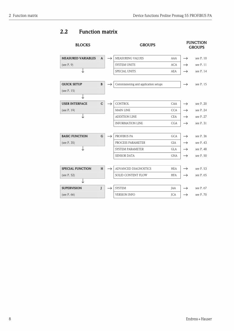
2.2 Function matrix
BLOCKS GROUPSFUNCTION
GROUPS
MEASURED VARIABLES A → MEASURING VALUES AAA → see P. 10
(see P. 9) SYSTEM UNITS ACA → see P. 11
↓ SPECIAL UNITS AEA → see P. 14
QUICK SETUP B → Commissioning and application setups → see P. 15
(see P. 15)
↓USER INTERFACE C → CONTROL CAA → see P. 20
(see P. 19) MAIN LINE CCA → see P. 24
↓ ADDITION LINE CEA → see P. 27
INFORMATION LINE CGA → see P. 31
BASIC FUNCTION G → PROFIBUS PA GCA → see P. 36
(see P. 35) PROCESS PARAMETER GIA → see P. 43
↓ SYSTEM PARAMETER GLA → see P. 48
SENSOR DATA GNA → see P. 50
SPECIAL FUNCTION H → ADVANCED DIAGNOSTICS HEA → see P. 53
(see P. 52) SOLID CONTENT FLOW HFA → see P. 65
↓SUPERVISION J → SYSTEM JAA → see P. 67
(see P. 66) VERSION INFO JCA → see P. 70

Device functions Proline Promag 55 PROFIBUS PA 3 Block MEASURED VARIABLES
Endress+Hauser 9
3 Block MEASURED VARIABLES
Fu
ncti
on
s
UN
IT V
OLU
ME
(04
03
) P
.1
2
DE
NSIT
Y
(00
05
) P
.1
0
UN
IT
VO
LU
ME
FLO
W
(04
02
) P
.1
2
VO
LU
ME
FLO
W
(00
01
) P
.1
0
UN
IT M
ASS
(04
01
) P
.1
1
UN
IT L
EN
GT
H
(04
24
) P
.1
3
⇒ ⇒ ⇒
CA
LC
.
MA
SS F
LO
W
(00
00
) P
.1
0
UN
IT
MA
SS F
LO
W
(04
00
) P
.1
1
UN
IT D
EN
SIT
Y
(04
20
) P
.1
3
VA
LU
E D
EN
SIT
Y
(07
00
) P
.1
4
⇒ ⇒ ⇒ ⇒
Fu
nct
ion
gro
up
s
MA
IN V
ALU
ES
(00
0)
P.10
CO
NFIG
UR
AT
ION
(04
0)
P.11
⇓ ⇑
AD
DIT
ION
AL
CO
NFIG
UR
AT
ION
(04
2)
P.13
DE
NSIT
Y
PA
RA
ME
TE
R
(07
0)
P.14
⇒ ⇒ ⇒
Gro
up
s
ME
ASU
RIN
G
VA
LU
ES
(AA
A)
P.1
0
⇓ ⇑
SY
ST
EM
UN
ITS
(AC
A)
P.
11
⇓ ⇑
⇓ ⇑
SPE
CIA
L U
NIT
S
(AE
A)
P.1
4
⇒
Blo
ck
ME
ASU
RE
D
VA
RIA
BLE
S
(A)

3 Block MEASURED VARIABLES Device functions Proline Promag 55 PROFIBUS PA
10 Endress+Hauser
3.1 Group MEASURING VALUES
3.1.1 Function group MAIN VALUES
MEASURED
VARIABLESA ⇒ MEASURING VALUES AAA ⇒ MAIN VALUES 000
Function descriptionMEASURED VARIABLES → MEASURING VALUES → MAIN VALUES
! Note!
• The engineering units of all the measured variables shown here can be set in the SYSTEM UNITS group.
• If the fluid in the pipe flows backwards, a negative sign prefixes the flow reading on the display.
CALCULATED MASS
FLOW
(0000)
Use this function to view the calculated mass flow. The mass flow is derived from the
measured volume flow and the fixed (or temperature-compensated) density.
User interface:
5-digit floating-point number, including unit and sign
(e.g. 462.87 kg/h; –731.63 lb/min; etc.)
VOLUME FLOW
(0001)
Use this function to view the actual measured volume flow.
User interface:
5-digit floating-point number, including unit and sign
(e.g. 5.5445 dm3/min; 1.4359 m3/h; –731.63 gal/d; etc.)
DENSITY
(0005)
Use this function to view the fixed density, temperature-compensated density or density
fed in via the current input.
User interface:
5-digit floating-point number, including unit (corresponding to 0.10000 to
6.0000 kg/dm3)
e.g. 1.2345 kg/dm3; 993.5 kg/m3; 1.0015 SG_20 °C; etc.

Device functions Proline Promag 55 PROFIBUS PA 3 Block MEASURED VARIABLES
Endress+Hauser 11
3.2 Group SYSTEM UNITS
3.2.1 Function group CONFIGURATION
MEASURED
VARIABLESA ⇒ MEASURING VALUES AAA
⇓ SYSTEM UNITS ACA ⇒ CONFIGURATION 040
Function descriptionMEASURED VARIABLES → SYSTEM UNITS → CONFIGURATION
You can select the units for measured variables in this function group.
! Note!
The factory settings for the system units which are described here apply to the local display and may differ from the units
which are used to transfer the measured variables to the automation system.
However, the SET UNIT TO BUS (6141) function (see P. 41) can be used to set these units to the units currently selected
for the local display.
UNIT MASS FLOW
(0400)
Use this function to select the unit for displaying the calculated mass flow (mass/time).
The mass flow is derived from the preset (compensated) specific fluid density and the
measured volume flow.
The unit you select here is also valid for:
• low flow
Options:
Metric:
Gram → g/s; g/min; g/h; g/day
Kilogram → kg/s; kg/min; kg/h; kg/day
Ton → t/s; t/min; t/h; t/day
US:
Ounce → oz/s; oz/min; oz/h; oz/day
Pound → lb/s; lb/min; lb/h; lb/day
Ton → ton/s; ton/min; ton/h; ton/day
Factory setting:
Depends on nominal diameter and country (s. Page 73 ff.).
UNIT MASS
(0401)
Use this function to select the unit for displaying the calculated mass. The mass is derived
from the preset (compensated) specific fluid density and the measured volume.
Options:
Metric → g; kg; t
US → oz; lb; ton
Factory setting:
Depends on nominal diameter and country (s. Page 73 ff.).
! Note!
The unit for the totalizers is independent of your choice here.
The unit for each totalizer is selected separately for the totalizer in question.
3 Block MEASURED VARIABLES Device functions Proline Promag 55 PROFIBUS PA
12 Endress+Hauser
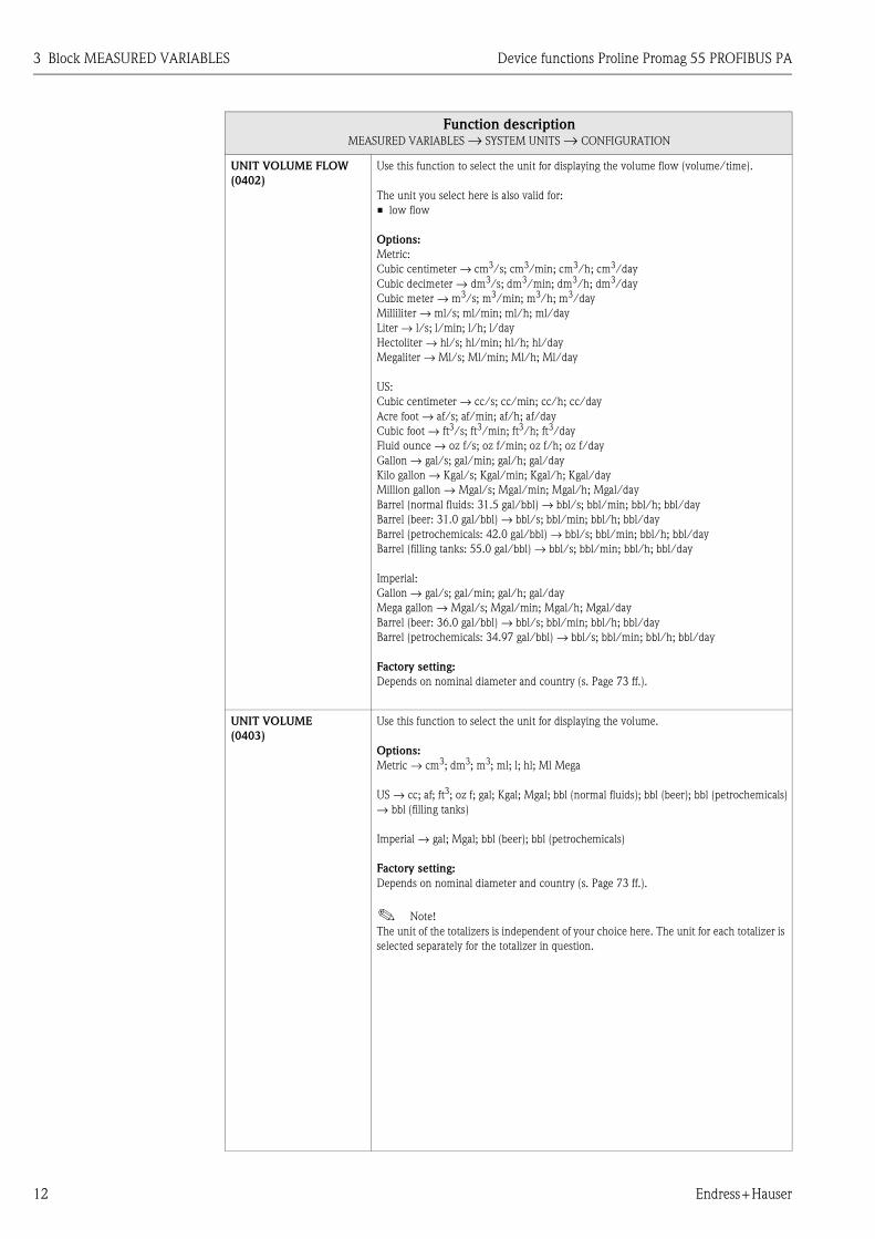
UNIT VOLUME FLOW
(0402)
Use this function to select the unit for displaying the volume flow (volume/time).
The unit you select here is also valid for:
• low flow
Options:
Metric:
Cubic centimeter → cm3/s; cm3/min; cm3/h; cm3/day
Cubic decimeter → dm3/s; dm3/min; dm3/h; dm3/day
Cubic meter → m3/s; m3/min; m3/h; m3/day
Milliliter → ml/s; ml/min; ml/h; ml/day
Liter → l/s; l/min; l/h; l/day
Hectoliter → hl/s; hl/min; hl/h; hl/day
Megaliter → Ml/s; Ml/min; Ml/h; Ml/day
US:
Cubic centimeter → cc/s; cc/min; cc/h; cc/day
Acre foot → af/s; af/min; af/h; af/day
Cubic foot → ft3/s; ft3/min; ft3/h; ft3/day
Fluid ounce → oz f/s; oz f/min; oz f/h; oz f/day
Gallon → gal/s; gal/min; gal/h; gal/day
Kilo gallon → Kgal/s; Kgal/min; Kgal/h; Kgal/day
Million gallon → Mgal/s; Mgal/min; Mgal/h; Mgal/day
Barrel (normal fluids: 31.5 gal/bbl) → bbl/s; bbl/min; bbl/h; bbl/day
Barrel (beer: 31.0 gal/bbl) → bbl/s; bbl/min; bbl/h; bbl/day
Barrel (petrochemicals: 42.0 gal/bbl) → bbl/s; bbl/min; bbl/h; bbl/day
Barrel (filling tanks: 55.0 gal/bbl) → bbl/s; bbl/min; bbl/h; bbl/day
Imperial:
Gallon → gal/s; gal/min; gal/h; gal/day
Mega gallon → Mgal/s; Mgal/min; Mgal/h; Mgal/day
Barrel (beer: 36.0 gal/bbl) → bbl/s; bbl/min; bbl/h; bbl/day
Barrel (petrochemicals: 34.97 gal/bbl) → bbl/s; bbl/min; bbl/h; bbl/day
Factory setting:
Depends on nominal diameter and country (s. Page 73 ff.).
UNIT VOLUME
(0403)
Use this function to select the unit for displaying the volume.
Options:
Metric → cm3; dm3; m3; ml; l; hl; Ml Mega
US → cc; af; ft3; oz f; gal; Kgal; Mgal; bbl (normal fluids); bbl (beer); bbl (petrochemicals)
→ bbl (filling tanks)
Imperial → gal; Mgal; bbl (beer); bbl (petrochemicals)
Factory setting:
Depends on nominal diameter and country (s. Page 73 ff.).
! Note!
The unit of the totalizers is independent of your choice here. The unit for each totalizer is
selected separately for the totalizer in question.
Function descriptionMEASURED VARIABLES → SYSTEM UNITS → CONFIGURATION
Device functions Proline Promag 55 PROFIBUS PA 3 Block MEASURED VARIABLES
Endress+Hauser 13
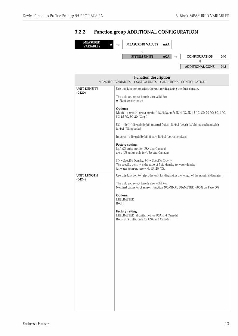
3.2.2 Function group ADDITIONAL CONFIGURATION
MEASURED
VARIABLESA ⇒ MEASURING VALUES AAA
⇓
SYSTEM UNITS ACA ⇒ CONFIGURATION 040
⇓ ADDITIONAL CONF. 042
Function descriptionMEASURED VARIABLES → SYSTEM UNITS → ADDITIONAL CONFIGURATION
UNIT DENSITY
(0420)
Use this function to select the unit for displaying the fluid density.
The unit you select here is also valid for:
• Fluid density entry
Options:
Metric → g/cm3; g/cc; kg/dm3; kg/l; kg/m3; SD 4 °C, SD 15 °C, SD 20 °C; SG 4 °C,
SG 15 °C, SG 20 °C; g/l
US → lb/ft3; lb/gal; lb/bbl (normal fluids); lb/bbl (beer); lb/bbl (petrochemicals);
lb/bbl (filling tanks)
Imperial → lb/gal; lb/bbl (beer); lb/bbl (petrochemicals)
Factory setting:
kg/l (SI units: not for USA and Canada)
g/cc (US units: only for USA and Canada)
SD = Specific Density, SG = Specific Gravity
The specific density is the ratio of fluid density to water density
(at water temperature = 4, 15, 20 °C).
UNIT LENGTH
(0424)
Use this function to select the unit for displaying the length of the nominal diameter.
The unit you select here is also valid for:
Nominal diameter of sensor (function NOMINAL DIAMETER (6804) on Page 50)
Options:
MILLIMETER
INCH
Factory setting:
MILLIMETER (SI units: not for USA and Canada)
INCH (US units: only for USA and Canada)
3 Block MEASURED VARIABLES Device functions Proline Promag 55 PROFIBUS PA
14 Endress+Hauser
3.3 Group SPECIAL UNITS
3.3.1 Function group DENSITY PARAMETER
MEASURED
VARIABLESA ⇒ MEASURING VALUES AAA
⇓
SYSTEM UNITS ACA
⇓
SPECIAL UNITS AEA ⇒ DENSITY PARAMETER 070
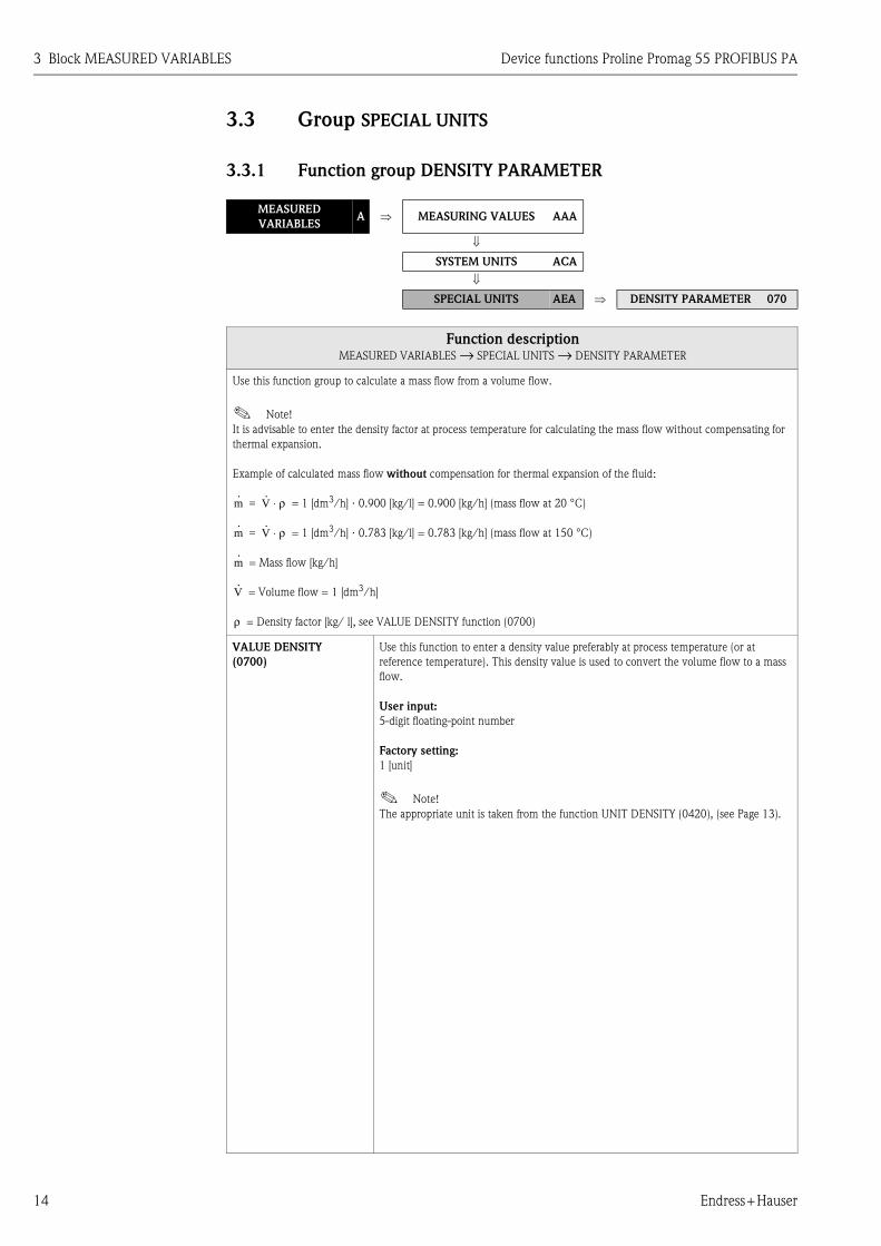
Function descriptionMEASURED VARIABLES → SPECIAL UNITS → DENSITY PARAMETER
Use this function group to calculate a mass flow from a volume flow.
! Note!
It is advisable to enter the density factor at process temperature for calculating the mass flow without compensating for
thermal expansion.
Example of calculated mass flow without compensation for thermal expansion of the fluid:
= 1 [dm3/h] ⋅ 0.900 [kg/l] = 0.900 [kg/h] (mass flow at 20 °C)
= 1 [dm3/h] ⋅ 0.783 [kg/l] = 0.783 [kg/h] (mass flow at 150 °C)
= Mass flow [kg/h]
= Volume flow = 1 [dm3/h]
= Density factor [kg/ l], see VALUE DENSITY function (0700)
VALUE DENSITY
(0700)
Use this function to enter a density value preferably at process temperature (or at
reference temperature). This density value is used to convert the volume flow to a mass
flow.
User input:
5-digit floating-point number
Factory setting:
1 [unit]
! Note!
The appropriate unit is taken from the function UNIT DENSITY (0420), (see Page 13).
m·
V· ρ⋅=
m·
V· ρ⋅=
m·
V·
ρ

Device functions Proline Promag 55 PROFIBUS PA 4 Block QUICK SETUP
Endress+Hauser 15
4 Block QUICK SETUP
Block GroupFunction
groupsFunctions
QUICK SETUP
(B) ⇒ ⇒QS COMMISS.
(1002) P. 15⇒
QS
COMMUNICATION
(1006) P. 15
T-DAT SAVE/LOAD
(1009) P. 15
Function descriptionQUICK SETUP
QUICK SETUP
COMMISSIONING
(1002)
Use this function to start the Setup menu for commissioning.
Options:
YES
NO
Factory setting:
NO
! Note!
You will find a flowchart of the COMMISSIONING Setup menu on Page 16.
For more detailed information on Setup menus, please refer to the Operating Instructions
Promag 55, BA119D/06/en/.
QUICK SETUP
COMMUNICATION
(1006)
Use this function to start the Setup menu for communication.
Options:
NO
YES
Factory setting:
NO
T-DAT SAVE/LOAD
(1009)
Use this function to save the parameter settings / configuration of the transmitter in a
transmitter DAT (T-DAT), or to load the parameter settings from the T-DAT into the
EEPROM (manual security function).
Application examples:
• After commissioning, the current measuring point parameters can be saved to the
T-DAT as a backup.
• If the transmitter is replaced for some reason, the data from the T-DAT can be loaded
into the new transmitter (EEPROM).
Options:
CANCEL
SAVE (from EEPROM to T-DAT)
LOAD (from the T-DAT into EEPROM)
Factory setting:
CANCEL
! Note!
• If the target device has an older software version, the message "TRANSM. SW-DAT" is
displayed during startup. Then only the SAVE option is available.
• LOAD
This option is only available if
– the target device has the same software version as, or a more recent software
version than, the source device or
– if the T-DAT contains valid data that can be retrieved.
• SAVE
This option is always available.

4 Block QUICK SETUP Device functions Proline Promag 55 PROFIBUS PA
16 Endress+Hauser
4.1 Quick Setup "Commissioning"
The "Commissioning" Quick Setup menu guides you systematically through all the important device
functions that have to be configured for standard operation.
a0005958-en
! Note!
• The display returns to the cell SETUP COMMISSIONING (1002) if you press the ESC key combination during
parameter interrogation. The stored parameters remain valid.
• The "Commissioning" Quick Setup must be carried out before one of the other Quick Setups explained in these
Operating Instructions is run.
• The system units selected via the Quick Setup only apply for displaying on the local display. They do not affect the
measured variables (volume flow, mass flow) that are transmitted via PROFIBUS.
m The "DELIVERY SETTINGS" option sets every selected unit to the factory setting.
The "ACTUAL SETTINGS" accepts the units you configured beforehand.
n Only units not yet configured in the current Setup are offered for selection in each cycle. The unit for mass and
volume is derived from the corresponding flow unit.
o The "YES" option remains visible until all the units have been configured.
"NO" is the only option displayed when no further units are available.
p The "automatic parameterization of the display" option contains the following basic settings/factory settings:
YES Main line = Volume flow
Additional line = Totalizer 1
Information line = Operating/system condition
NO The existing (selected) settings remain.
n
3001
3001
++ +EEsc
E+-
XXX.XXX.XX
+E
m
o
p
Deliver Settingsy
Selection pre-settings
Actual Settings
0402UnitVolume Flow
Volume Flow Mass Flow Quit
Configure another unit? NOYES
UnitDensity
ValueDensity
UnitTotalizer
UnitTotalizer
UnitMass Flow
SelectionSystem units
0420
0700
0400
Autom. Configurationof Display? NO
NO
YES
Automatic parameterizationof the display
AnotherQuick Setup?
Quick Setupcomplete
Commission
Language
Pre-Setting
Quick Setup
HOME-POSITION
QS 1002
2000
B
Device functions Proline Promag 55 PROFIBUS PA 4 Block QUICK SETUP
Endress+Hauser 17
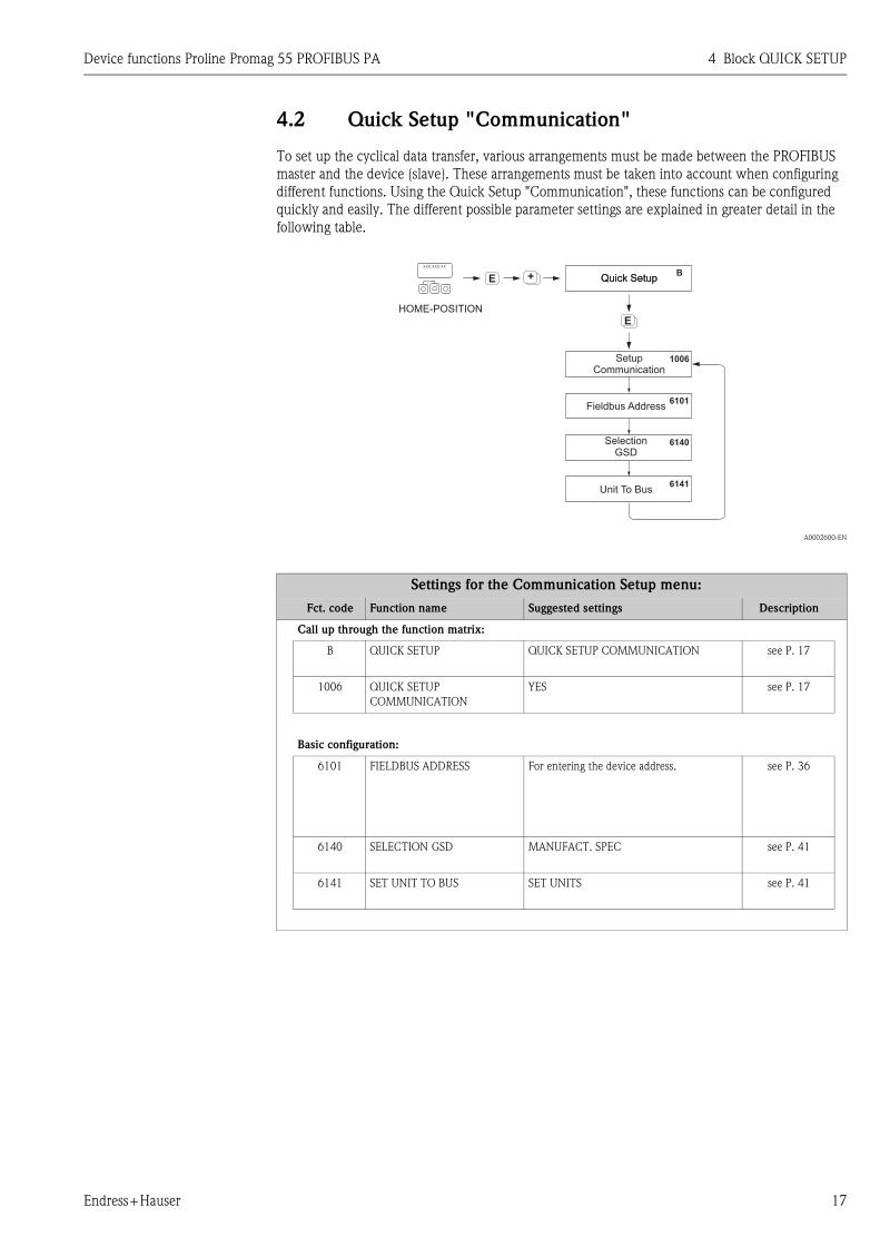
4.2 Quick Setup "Communication"
To set up the cyclical data transfer, various arrangements must be made between the PROFIBUS
master and the device (slave). These arrangements must be taken into account when configuring
different functions. Using the Quick Setup "Communication", these functions can be configured
quickly and easily. The different possible parameter settings are explained in greater detail in the
following table.
A0002600-EN
Settings for the Communication Setup menu:
Fct. code Function name Suggested settings Description
Call up through the function matrix:
B QUICK SETUP QUICK SETUP COMMUNICATION see P. 17
1006 QUICK SETUP
COMMUNICATION
YES see P. 17
Basic configuration:
6101 FIELDBUS ADDRESS For entering the device address. see P. 36
6140 SELECTION GSD MANUFACT. SPEC see P. 41
6141 SET UNIT TO BUS SET UNITS see P. 41
++E
+E
BQuick SetupQuick Setup
6101
6140
6141
1006
Esc
E+-
XXX.XXX.XX
HOME-POSITION
Fieldbus Address
SelectionGSD
Unit To Bus
SetupCommunication

4 Block QUICK SETUP Device functions Proline Promag 55 PROFIBUS PA
18 Endress+Hauser
4.3 Data backup/transmission
Using the T-DAT SAVE/LOAD function, you can transfer data (device parameters and settings)
between the T-DAT (exchangeable memory) and the EEPROM (device storage unit).
This is required in the following instances:
• Creating a backup: current data are transferred from an EEPROM to the T-DAT.
• Replacing a transmitter: current data are copied from an EEPROM to the T-DAT and then
transferred to the EEPROM of the new transmitter.
• Duplicating data: current data are copied from an EEPROM to the T-DAT and then transferred to
EEPROMs of identical measuring points.
! Note!
For information on installing and removing the T-DAT → see Operation Instructions
Proline Promag 55 PROFIBUS PA
a0001221-en
Data backup/transmission with T-DAT SAVE/LOAD function
Information on the LOAD and SAVE options available:
LOAD: Data are transferred from the T-DAT to the EEPROM.
! Hinweis!
• Any settings already saved on the EEPROM are deleted.
• This option is only available, if the T-DAT contains valid data.
• This option can only be executed if the software version of the T-DAT is the same or newer than
that of the EEPROM. Otherwise, the error message "TRANSM. SW-DAT" appears after restarting
and the LOAD function is then no longer available.
SAVE:
Data are transferred from the EEPROM to the T-DAT
FEsc
E+-
XXX.XXX.XX
F F
FF FF
P P
PP
N
O
T-DATSAVE/LOAD
Quick Setup
HOMEPOSITION
LOAD
YES NO
CANCELSAVE
YES NO
Restart of themeasuring device
Input issaved
Device functions Proline Promag 55 PROFIBUS PA 5 Block USER INTERFACE
Endress+Hauser 19
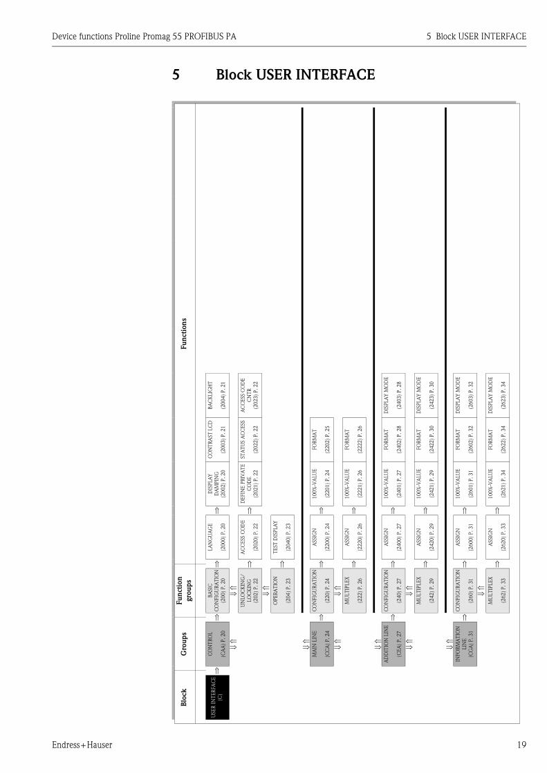
5 Block USER INTERFACE
Fu
ncti
on
s
BA
CK
LIG
HT
(20
04
) P
.2
1
AC
CE
SS C
OD
E
CN
TR
(20
23
) P
.2
2
DIS
PLA
Y M
OD
E
(24
03
) P
.2
8
DIS
PLA
Y M
OD
E
(24
23
) P
.3
0
DIS
PLA
Y M
OD
E
(26
03
) P
.3
2
DIS
PLA
Y M
OD
E
(26
23
) P
.3
4
CO
NT
RA
ST
LC
D
(20
03
) P
.2
1
ST
AT
US A
CC
ESS
(20
22
) P
.2
2
FO
RM
AT
(22
02
) P
.2
5
FO
RM
AT
(22
22
) P
.2
6
FO
RM
AT
(24
02
) P
.2
8
FO
RM
AT
(24
22
) P
.3
0
FO
RM
AT
(26
02
) P
.3
2
FO
RM
AT
(26
22
) P
.3
4
DIS
PLA
Y
DA
MPIN
G
(20
02
) P
.2
0
DE
FIN
E P
RIV
AT
E
CO
DE
(20
21
) P
.2
2
100%
-VA
LU
E
(22
01
) P
.2
4
100%
-VA
LU
E
(22
21
) P
.2
6
100%
-VA
LU
E
(24
01
) P
.2
7
100%
-VA
LU
E
(24
21
) P
.2
9
100%
-VA
LU
E
(26
01
) P
.3
1
100%
-VA
LU
E
(26
21
) P
.3
4
⇒ ⇒ ⇒ ⇒ ⇒ ⇒ ⇒ ⇒
LA
NG
UA
GE
(20
00
) P
.2
0
AC
CE
SS C
OD
E
(20
20
) P
.2
2
TE
ST
DIS
PLA
Y
(20
40
) P
.2
3
ASSIG
N
(22
00
) P
.2
4
ASSIG
N
(22
20
) P
.2
6
ASSIG
N
(24
00
) P
.2
7
ASSIG
N
(24
20
) P
.2
9
ASSIG
N
(26
00
) P
.3
1
ASSIG
N
(26
20
) P
.3
3
⇒ ⇒ ⇒ ⇒ ⇒ ⇒ ⇒ ⇒ ⇒
Fu
nct
ion
gro
up
s
BA
SIC
CO
NFIG
UR
AT
ION
(20
0)
P.20
⇓ ⇑
UN
LO
CK
ING
/
LO
CK
ING
(20
2)
P.22
⇓ ⇑
OP
ER
AT
ION
(20
4)
P.23
CO
NFIG
UR
AT
ION
(22
0)
P.24
⇓ ⇑
MU
LT
IPLE
X
(22
2)
P.26
CO
NFIG
UR
AT
ION
(24
0)
P.27
⇓ ⇑
MU
LT
IPLE
X
(24
2)
P.29
CO
NFIG
UR
AT
ION
(26
0)
P.31
⇓ ⇑
MU
LT
IPLE
X
(26
2)
P.33
⇒ ⇒ ⇒ ⇒
Gro
up
s
CO
NT
RO
L
(CA
A)
P.2
0
⇓ ⇑
⇓ ⇑
MA
IN L
INE
(CC
A)
P.
24
⇓ ⇑
⇓ ⇑
AD
DIT
ION
LIN
E
(CE
A)
P.2
7
⇓ ⇑
⇓ ⇑
INFO
RM
AT
ION
LIN
E
(CG
A)
P.
31
⇒
Blo
ck
USE
R I
NT
ER
FA
CE
(C)
5 Block USER INTERFACE Device functions Proline Promag 55 PROFIBUS PA
20 Endress+Hauser
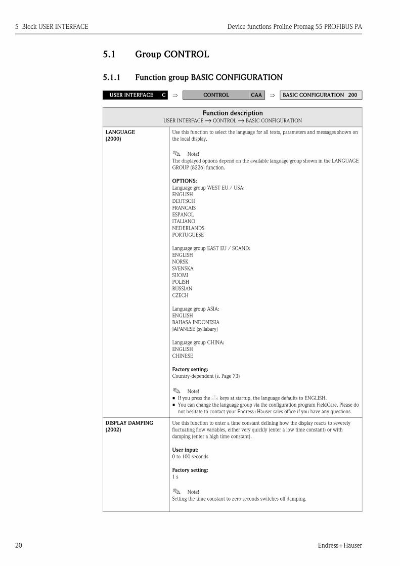
5.1 Group CONTROL
5.1.1 Function group BASIC CONFIGURATION
USER INTERFACE C ⇒ CONTROL CAA ⇒ BASIC CONFIGURATION 200
Function descriptionUSER INTERFACE → CONTROL → BASIC CONFIGURATION
LANGUAGE
(2000)
Use this function to select the language for all texts, parameters and messages shown on
the local display.
! Note!
The displayed options depend on the available language group shown in the LANGUAGE
GROUP (8226) function.
OPTIONS:
Language group WEST EU / USA:
ENGLISH
DEUTSCH
FRANCAIS
ESPANOL
ITALIANO
NEDERLANDS
PORTUGUESE
Language group EAST EU / SCAND:
ENGLISH
NORSK
SVENSKA
SUOMI
POLISH
RUSSIAN
CZECH
Language group ASIA:
ENGLISH
BAHASA INDONESIA
JAPANESE (syllabary)
Language group CHINA:
ENGLISH
CHINESE
Factory setting:
Country-dependent (s. Page 73)
! Note!
• If you press the X keys at startup, the language defaults to ENGLISH.
• You can change the language group via the configuration program FieldCare. Please do
not hesitate to contact your Endress+Hauser sales office if you have any questions.
DISPLAY DAMPING
(2002)
Use this function to enter a time constant defining how the display reacts to severely
fluctuating flow variables, either very quickly (enter a low time constant) or with
damping (enter a high time constant).
User input:
0 to 100 seconds
Factory setting:
1 s
! Note!
Setting the time constant to zero seconds switches off damping.

Device functions Proline Promag 55 PROFIBUS PA 5 Block USER INTERFACE
Endress+Hauser 21
CONTRAST LCD
(2003)
Use this function to optimize display contrast to suit local operating conditions.
User input:
10 to 100%
Factory setting:
50%
BACKLIGHT
(2004)
Use this function to optimize the backlight to suit local operating conditions.
User input:
0 to 100%
! Note!
Entering the value "0" means that the backlight is switched off. The display then no
longer emits any light, i.e. the display texts can no longer be read in the dark.
Factory setting:
50%
Function descriptionUSER INTERFACE → CONTROL → BASIC CONFIGURATION
5 Block USER INTERFACE Device functions Proline Promag 55 PROFIBUS PA
22 Endress+Hauser
5.1.2 Function group UNLOCKING/LOCKING
USER INTERFACE C ⇒ CONTROL CAA ⇒ BASIC CONFIGURATION 200
⇓ UNLOCKING/LOCKING 202
Function descriptionUSER INTERFACE → CONTROL → UNLOCKING/LOCKING
ACCESS CODE
(2020) ! Note!
This function is only relevant for local operation and accessing via an operating program
(e.g. FieldCare) and does not affect cyclic data transmission via the PROFIBUS master
(Class 1).
All data of the measuring system are protected against inadvertent change. Programming
is disabled and the settings cannot be changed until a code is entered in this function. If
you press the X keys in any function, the measuring system automatically goes to this
function and the prompt to enter the code appears on the display (when programming is
disabled).
You can enable programming by entering your personal code
(factory setting = 55, see function 2021).
User input:
max. 4-digit number: 0 to 9999
! Note!
• Programming is disabled if you do not press a key within 60 seconds following
automatic return to the HOME position.
• You can also disable programming in this function by entering any number (other than
the defined private code).
• The Endress+Hauser service organization can be of assistance if you mislay your
personal code.
DEFINE PRIVATE CODE
(2021)
Use this function to specify a personal code for enabling programming in the function
ACCESS CODE.
User input:
0 to 9999 (max. 4-digit number)
Factory setting:
55
! Note!
• Programming is always enabled with the code "0".
• Programming has to be enabled before this code can be changed. When programming
is disabled this function is not available, thus preventing others from accessing your
personal code.
STATUS ACCESS
(2022)
Use this function to check the access status for the function matrix.
User interface:
ACCESS CUSTOMER (parameterization possible)
LOCKED (parameterization disabled)
ACCESS CODE
COUNTER
(2023)
Displays how often the customer code, service code or the digit "0" (code-free) has been
entered to gain access to the function matrix.
User interface:
max. 7-digit number: 0 to 9999999
Factory setting:
0

Device functions Proline Promag 55 PROFIBUS PA 5 Block USER INTERFACE
Endress+Hauser 23
5.1.3 Function group OPERATION
USER INTERFACE C ⇒ CONTROL CAA ⇒ BASIC CONFIGURATION 200
⇓ UNLOCKING/LOCKING 202
⇓
OPERATION 204
Function descriptionUSER INTERFACE → CONTROL → OPERATION
TEST DISPLAY
(2040)
Use this function to test the operability of the local display and its pixels.
Options:
OFF
ON
Factory setting:
OFF
Test sequence:
1. Start the test by selecting ON.
2. All pixels of the main line, additional line and information line are darkened for
minimum 0.75 seconds.
3. Main line, additional line and information line show an "8" in each field for minimum
0.75 seconds.
4. Main line, additional line and information line show a "0" in each field for minimum
0.75 seconds.
5. Main line, additional line and information line show nothing (blank display) for
minimum 0.75 seconds.
When the test completes the local display returns to its initial state and the setting
changes to OFF.
5 Block USER INTERFACE Device functions Proline Promag 55 PROFIBUS PA
24 Endress+Hauser
5.2 Group MAIN LINE
5.2.1 Function group CONFIGURATION
USER INTERFACE C ⇒ CONTROL CAA
⇓ MAIN LINE CCA ⇒ CONFIGURATION 220
Function descriptionUSER INTERFACE → MAIN LINE → CONFIGURATION
A0001253
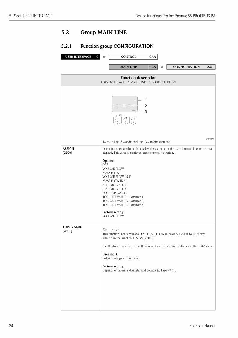
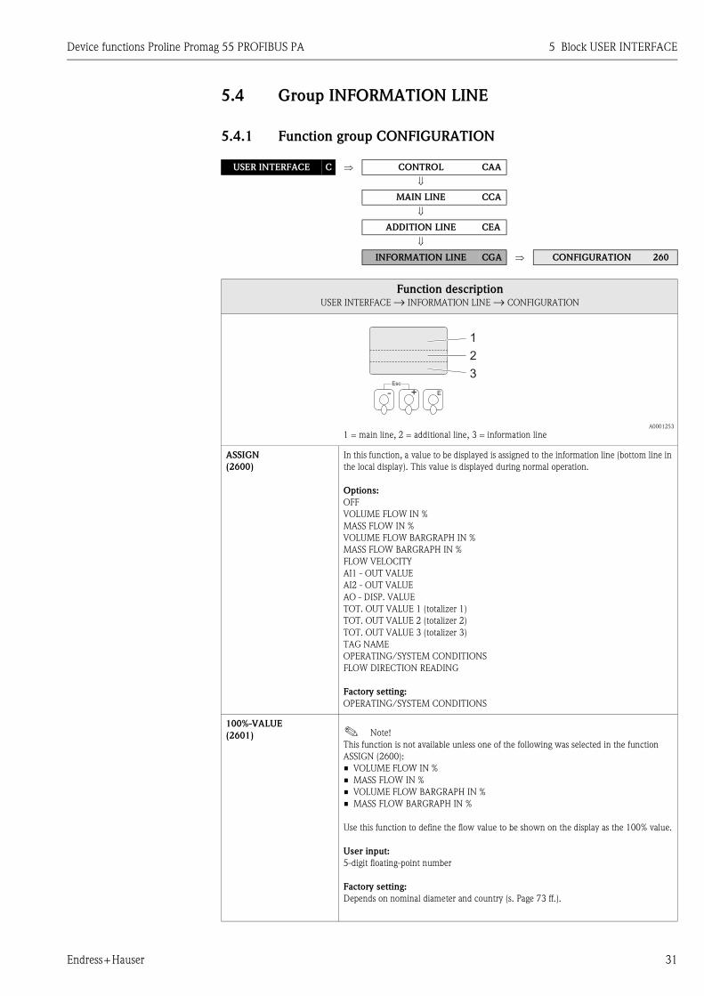
1= main line, 2 = additional line, 3 = information line
ASSIGN
(2200)
In this function, a value to be displayed is assigned to the main line (top line in the local
display). This value is displayed during normal operation.
Options:
OFF
VOLUME FLOW
MASS FLOW
VOLUME FLOW IN %
MASS FLOW IN %
AI1 - OUT VALUE
AI2 - OUT VALUE
AO - DISP. VALUE
TOT. OUT VALUE 1 (totalizer 1)
TOT. OUT VALUE 2 (totalizer 2)
TOT. OUT VALUE 3 (totalizer 3)
Factory setting:
VOLUME FLOW
100%-VALUE
(2201) ! Note!
This function is only available if VOLUME FLOW IN % or MASS FLOW IN % was
selected in the function ASSIGN (2200).
Use this function to define the flow value to be shown on the display as the 100% value.
User input:
5-digit floating-point number
Factory setting:
Depends on nominal diameter and country (s. Page 73 ff.).
Esc
E+-
1
2
3

Device functions Proline Promag 55 PROFIBUS PA 5 Block USER INTERFACE
Endress+Hauser 25
FORMAT
(2202)
Use this function to define the maximum number of places after the decimal point
displayed for the reading in the main line.
Options:
XXXXX. – XXXX.X – XXX.XX – XX.XXX – X.XXXX
Factory setting:
X.XXXX
! Note!
• Note that this setting only affects the reading as it appears on the display, it has no
influence on the accuracy of the system's calculations.
• The places after the decimal point as computed by the measuring device cannot always
be displayed, depending on this setting and the engineering unit. In such instances an
arrow appears on the display between the measuring value and the engineering unit
(e.g. 1.2 → kg/h), indicating that the measuring system is computing with more
decimal places than can be shown on the display.
Function descriptionUSER INTERFACE → MAIN LINE → CONFIGURATION
5 Block USER INTERFACE Device functions Proline Promag 55 PROFIBUS PA
26 Endress+Hauser
5.2.2 Function group MULTIPLEX
USER INTERFACE C ⇒ CONTROL CAA
⇓
MAIN LINE CCA ⇒ CONFIGURATION 220
⇓ MULTIPLEX 222
Function descriptionUSER INTERFACE → MAIN LINE → MULTIPLEX
ASSIGN
(2220)
Use this function to define the second reading to be displayed in the main line alternately
(every 10 seconds) with the value defined in the ASSIGN function (2200).
Options:
OFF
VOLUME FLOW
MASS FLOW
VOLUME FLOW IN %
MASS FLOW IN %
AI1 - OUT VALUE
AI2 - OUT VALUE
AO - DISP. VALUE
TOT. OUT VALUE 1 (totalizer 1)
TOT. OUT VALUE 2 (totalizer 2)
TOT. OUT VALUE 3 (totalizer 3)
Factory setting:
OFF
100%-VALUE
(2221) ! Note!
This function is only available if VOLUME FLOW IN % or MASS FLOW IN % was
selected in the function ASSIGN (2220).
Use this function to define the flow value to be shown on the display as the 100% value.
User input:
5-digit floating-point number
Factory setting:
Depends on nominal diameter and country (s. Page 73 ff.).
FORMAT
(2222)
Use this function to define the maximum number of places after the decimal point for the
second value displayed in the main line.
Options:
XXXXX. – XXXX.X – XXX.XX – XX.XXX – X.XXXX
Factory setting:
X.XXXX
! Note!
• Note that this setting only affects the reading as it appears on the display, it has no
influence on the accuracy of the system's calculations.
• The places after the decimal point as computed by the measuring device cannot always
be displayed, depending on this setting and the engineering unit. In such instances an
arrow appears on the display between the measuring value and the engineering unit
(e.g. 1.2 → kg/h), indicating that the measuring system is computing with more
decimal places than can be shown on the display.

Device functions Proline Promag 55 PROFIBUS PA 5 Block USER INTERFACE
Endress+Hauser 27
5.3 Group ADDITION LINE
5.3.1 Function group CONFIGURATION
USER INTERFACE C ⇒ CONTROL CAA
⇓ MAIN LINE CCA
⇓
ADDITION LINE CEA ⇒ CONFIGURATION 240
Function descriptionUSER INTERFACE → ADDITION LINE → CONFIGURATION
A0001253
1= main line, 2 = additional line, 3 = information line
ASSIGN
(2400)
In this function, a value to be displayed is assigned to the additional line (middle line in
the local display). This value is displayed during normal operation.
Options:
OFF
VOLUME FLOW
MASS FLOW
VOLUME FLOW IN %
MASS FLOW IN %
VOLUME FLOW BARGRAPH IN %
MASS FLOW BARGRAPH IN %
FLOW VELOCITY
AI1 - OUT VALUE
AI2 - OUT VALUE
AO - DISP. VALUE
TOT. OUT VALUE 1 (totalizer 1)
TOT. OUT VALUE 2 (totalizer 2)
TOT. OUT VALUE 3 (totalizer 3)
TAG NAME
Factory setting:
TOT. OUT VALUE 1 (totalizer 1)
100%-VALUE
(2401) ! Note!
This function is not available unless one of the following was selected in the function
ASSIGN (2400):
• VOLUME FLOW IN %
• MASS FLOW IN %
• VOLUME FLOW BARGRAPH IN %
• MASS FLOW BARGRAPH IN %
Use this function to define the flow value to be shown on the display as the 100% value.
User input:
5-digit floating-point number
Factory setting:
Depends on nominal diameter and country (s. Page 73 ff.).
Esc
E+-
1
2
3
5 Block USER INTERFACE Device functions Proline Promag 55 PROFIBUS PA
28 Endress+Hauser
FORMAT
(2402) ! Note!
This function is not available unless a number was selected in the ASSIGN function
(2400).
Use this function to define the maximum number of places after the decimal point
displayed for the reading in the additional line.
Options:
XXXXX. – XXXX.X – XXX.XX – XX.XXX – X.XXXX
Factory setting:
X.XXXX
! Note!
• Note that this setting only affects the reading as it appears on the display, it has no
influence on the accuracy of the system's calculations.
• The places after the decimal point as computed by the measuring device cannot always
be displayed, depending on this setting and the engineering unit. In such instances an
arrow appears on the display between the measuring value and the engineering unit
(e.g. 1.2 → kg/h), indicating that the measuring system is computing with more
decimal places than can be shown on the display.
DISPLAY MODE
(2403) ! Note!
This function is only available if VOLUME FLOW BARGRAPH IN % or MASS FLOW
BARGRAPH IN % was selected in the function ASSIGN (2400).
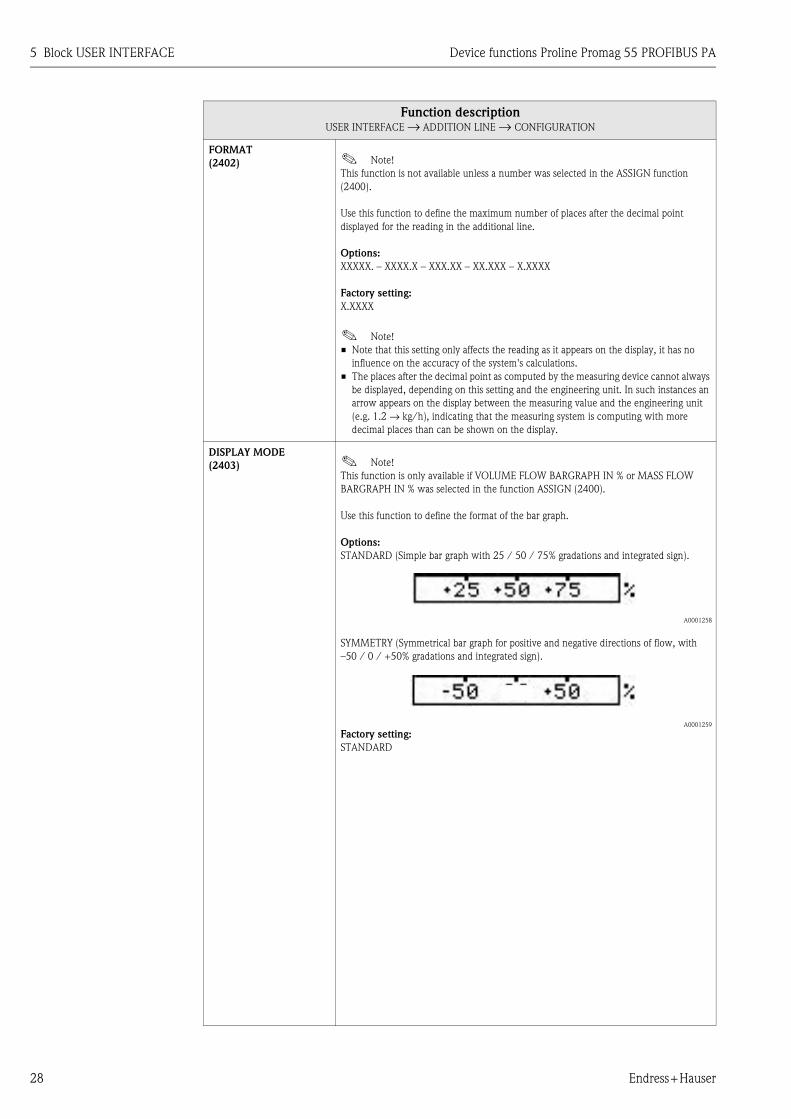
Use this function to define the format of the bar graph.
Options:
STANDARD (Simple bar graph with 25 / 50 / 75% gradations and integrated sign).
A0001258
SYMMETRY (Symmetrical bar graph for positive and negative directions of flow, with
–50 / 0 / +50% gradations and integrated sign).
A0001259
Factory setting:
STANDARD
Function descriptionUSER INTERFACE → ADDITION LINE → CONFIGURATION

Device functions Proline Promag 55 PROFIBUS PA 5 Block USER INTERFACE
Endress+Hauser 29
5.3.2 Function group MULTIPLEX
USER INTERFACE C ⇒ CONTROL CAA
⇓ MAIN LINE CCA
⇓ ADDITION LINE CEA ⇒ CONFIGURATION 240
⇓ MULTIPLEX 242
Function descriptionUSER INTERFACE → ADDITION LINE → MULTIPLEX
ASSIGN
(2420)
Use this function to define the second reading to be displayed in the additional line
alternately (every 10 seconds) with the value defined in the function ASSIGN (2400).
Options:
OFF
VOLUME FLOW
MASS FLOW
VOLUME FLOW IN %
MASS FLOW IN %
VOLUME FLOW BARGRAPH IN %
MASS FLOW BARGRAPH IN %
FLOW VELOCITY
AI1 - OUT VALUE
AI2 - OUT VALUE
AO - DISP. VALUE
TOT. OUT VALUE 1 (totalizer 1)
TOT. OUT VALUE 2 (totalizer 2)
TOT. OUT VALUE 3 (totalizer 3)
TAG NAME
Factory setting:
OFF
! Note!
Multiplex mode is suspended as soon as a fault / notice message is generated. The
message in question appears on the display. Once the fault is eliminated, the measuring
device resumes operation in Multiplex mode and the error message is no longer displayed
on the local display.
100%-VALUE
(2421) ! Note!
This function is not available unless one of the following was selected in the function
ASSIGN (2420):
• VOLUME FLOW IN %
• MASS FLOW IN %
• VOLUME FLOW BARGRAPH IN %
• MASS FLOW BARGRAPH IN %
Use this function to define the flow value to be shown on the display as the 100% value.
User input:
5-digit floating-point number
Factory setting:
Depends on nominal diameter and country (s. Page 73 ff.).

5 Block USER INTERFACE Device functions Proline Promag 55 PROFIBUS PA
30 Endress+Hauser
FORMAT
(2422) ! Note!
This function is not available unless a number was selected in the ASSIGN function
(2420).
Use this function to define the maximum number of places after the decimal point for the
second value displayed in the additional line.
Options:
XXXXX. – XXXX.X – XXX.XX – XX.XXX – X.XXXX
Factory setting:
X.XXXX
! Note!
• Note that this setting only affects the reading as it appears on the display, it has no
influence on the accuracy of the system's calculations.
• The places after the decimal point as computed by the measuring device cannot always
be displayed, depending on this setting and the engineering unit. In such instances an
arrow appears on the display between the measuring value and the engineering unit
(e.g. 1.2 → kg/h), indicating that the measuring system is computing with more
decimal places than can be shown on the display.
DISPLAY MODE
(2423) ! Note!
This function is only available if VOLUME FLOW BARGRAPH IN % or MASS FLOW
BARGRAPH IN % was selected in the function ASSIGN (2420).
Use this function to define the format of the bar graph.
Options:
STANDARD (Simple bar graph with 25 / 50 / 75% gradations and integrated sign).
A0001258
SYMMETRY (Symmetrical bar graph for positive and negative directions of flow, with
–50 / 0 / +50% gradations and integrated sign).
A0001259
Factory setting:
STANDARD
Function descriptionUSER INTERFACE → ADDITION LINE → MULTIPLEX
Device functions Proline Promag 55 PROFIBUS PA 5 Block USER INTERFACE
Endress+Hauser 31
5.4 Group INFORMATION LINE
5.4.1 Function group CONFIGURATION
USER INTERFACE C ⇒ CONTROL CAA
⇓
MAIN LINE CCA
⇓ ADDITION LINE CEA
⇓ INFORMATION LINE CGA ⇒ CONFIGURATION 260
Function descriptionUSER INTERFACE → INFORMATION LINE → CONFIGURATION
A0001253
1 = main line, 2 = additional line, 3 = information line
ASSIGN
(2600)
In this function, a value to be displayed is assigned to the information line (bottom line in
the local display). This value is displayed during normal operation.
Options:
OFF
VOLUME FLOW IN %
MASS FLOW IN %
VOLUME FLOW BARGRAPH IN %
MASS FLOW BARGRAPH IN %
FLOW VELOCITY
AI1 - OUT VALUE
AI2 - OUT VALUE
AO - DISP. VALUE
TOT. OUT VALUE 1 (totalizer 1)
TOT. OUT VALUE 2 (totalizer 2)
TOT. OUT VALUE 3 (totalizer 3)
TAG NAME
OPERATING/SYSTEM CONDITIONS
FLOW DIRECTION READING
Factory setting:
OPERATING/SYSTEM CONDITIONS
100%-VALUE
(2601) ! Note!
This function is not available unless one of the following was selected in the function
ASSIGN (2600):
• VOLUME FLOW IN %
• MASS FLOW IN %
• VOLUME FLOW BARGRAPH IN %
• MASS FLOW BARGRAPH IN %
Use this function to define the flow value to be shown on the display as the 100% value.
User input:
5-digit floating-point number
Factory setting:
Depends on nominal diameter and country (s. Page 73 ff.).
Esc
E+-
1
2
3

5 Block USER INTERFACE Device functions Proline Promag 55 PROFIBUS PA
32 Endress+Hauser
FORMAT
(2602) ! Note!
This function is not available unless a number was selected in the ASSIGN function
(2600).
Use this function to define the maximum number of places after the decimal point
displayed for the reading in the information line.
Options:
XXXXX. – XXXX.X – XXX.XX – XX.XXX – X.XXXX
Factory setting:
X.XXXX
! Note!
• Note that this setting only affects the reading as it appears on the display, it has no
influence on the accuracy of the system's calculations.
• The places after the decimal point as computed by the measuring device cannot always
be displayed, depending on this setting and the engineering unit. In such instances an
arrow appears on the display between the measuring value and the engineering unit
(e.g. 1.2 → kg/h), indicating that the measuring system is computing with more
decimal places than can be shown on the display.
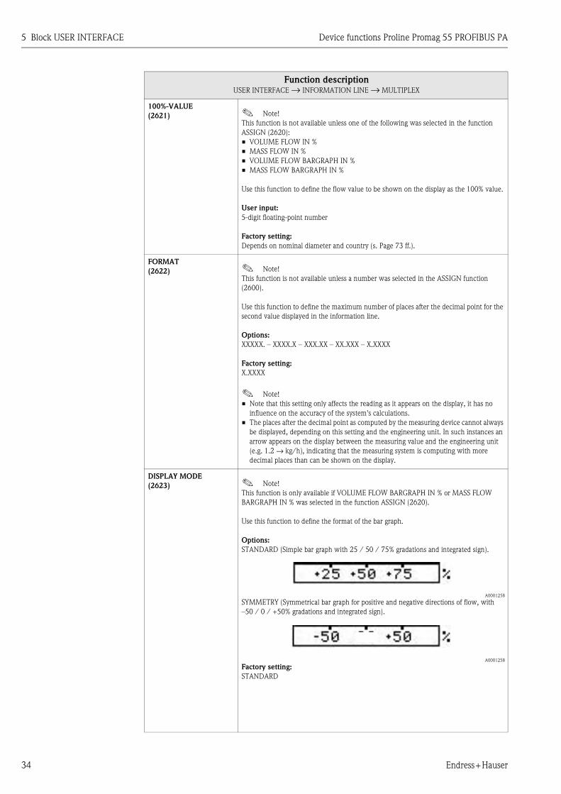
DISPLAY MODE
(2603) ! Note!
This function is only available if VOLUME FLOW BARGRAPH IN % or MASS FLOW
BARGRAPH IN % was selected in the function ASSIGN (2600).
Use this function to define the format of the bar graph.
Options:
STANDARD (Simple bar graph with 25 / 50 / 75% gradations and integrated sign).
A0001258
SYMMETRY (Symmetrical bar graph for positive and negative directions of flow, with
–50 / 0 / +50% gradations and integrated sign).
A0001259
Factory setting:
STANDARD
Function descriptionUSER INTERFACE → INFORMATION LINE → CONFIGURATION
Device functions Proline Promag 55 PROFIBUS PA 5 Block USER INTERFACE
Endress+Hauser 33
5.4.2 Function group MULTIPLEX
USER INTERFACE C ⇒ CONTROL CAA
⇓ MAIN LINE CCA
⇓ ADDITION LINE CEA
⇓ INFORMATION LINE CGA ⇒ CONFIGURATION 260
⇓
MULTIPLEX 262
Function descriptionUSER INTERFACE → INFORMATION LINE → MULTIPLEX
ASSIGN
(2620)
Use this function to define the second reading to be displayed in the information line
alternately (every 10 seconds) with the value defined in the function ASSIGN (2600).
Options:
OFF
VOLUME FLOW IN %
MASS FLOW IN %
VOLUME FLOW BARGRAPH IN %
MASS FLOW BARGRAPH IN %
FLOW VELOCITY
AI1 - OUT VALUE
AI2 - OUT VALUE
AO - DISP. VALUE
TOT. OUT VALUE 1 (totalizer 1)
TOT. OUT VALUE 2 (totalizer 2)
TOT. OUT VALUE 3 (totalizer 3)
TAG NAME
OPERATING/SYSTEM CONDITIONS
FLOW DIRECTION READING
Factory setting:
OFF
! Note!
Multiplex mode is suspended as soon as a fault / notice message is generated. The
message in question appears on the display. Once the fault is eliminated, the measuring
device resumes operation in Multiplex mode and the error message is no longer displayed
on the local display.
5 Block USER INTERFACE Device functions Proline Promag 55 PROFIBUS PA
34 Endress+Hauser
100%-VALUE
(2621) ! Note!
This function is not available unless one of the following was selected in the function
ASSIGN (2620):
• VOLUME FLOW IN %
• MASS FLOW IN %
• VOLUME FLOW BARGRAPH IN %
• MASS FLOW BARGRAPH IN %
Use this function to define the flow value to be shown on the display as the 100% value.
User input:
5-digit floating-point number
Factory setting:
Depends on nominal diameter and country (s. Page 73 ff.).
FORMAT
(2622) ! Note!
This function is not available unless a number was selected in the ASSIGN function
(2600).
Use this function to define the maximum number of places after the decimal point for the
second value displayed in the information line.
Options:
XXXXX. – XXXX.X – XXX.XX – XX.XXX – X.XXXX
Factory setting:
X.XXXX
! Note!
• Note that this setting only affects the reading as it appears on the display, it has no
influence on the accuracy of the system's calculations.
• The places after the decimal point as computed by the measuring device cannot always
be displayed, depending on this setting and the engineering unit. In such instances an
arrow appears on the display between the measuring value and the engineering unit
(e.g. 1.2 → kg/h), indicating that the measuring system is computing with more
decimal places than can be shown on the display.
DISPLAY MODE
(2623) ! Note!
This function is only available if VOLUME FLOW BARGRAPH IN % or MASS FLOW
BARGRAPH IN % was selected in the function ASSIGN (2620).
Use this function to define the format of the bar graph.
Options:
STANDARD (Simple bar graph with 25 / 50 / 75% gradations and integrated sign).
A0001258
SYMMETRY (Symmetrical bar graph for positive and negative directions of flow, with
–50 / 0 / +50% gradations and integrated sign).
A0001258
Factory setting:
STANDARD
Function descriptionUSER INTERFACE → INFORMATION LINE → MULTIPLEX
Device functions Proline Promag 55 PROFIBUS PA 6 Block BASIC FUNCTION
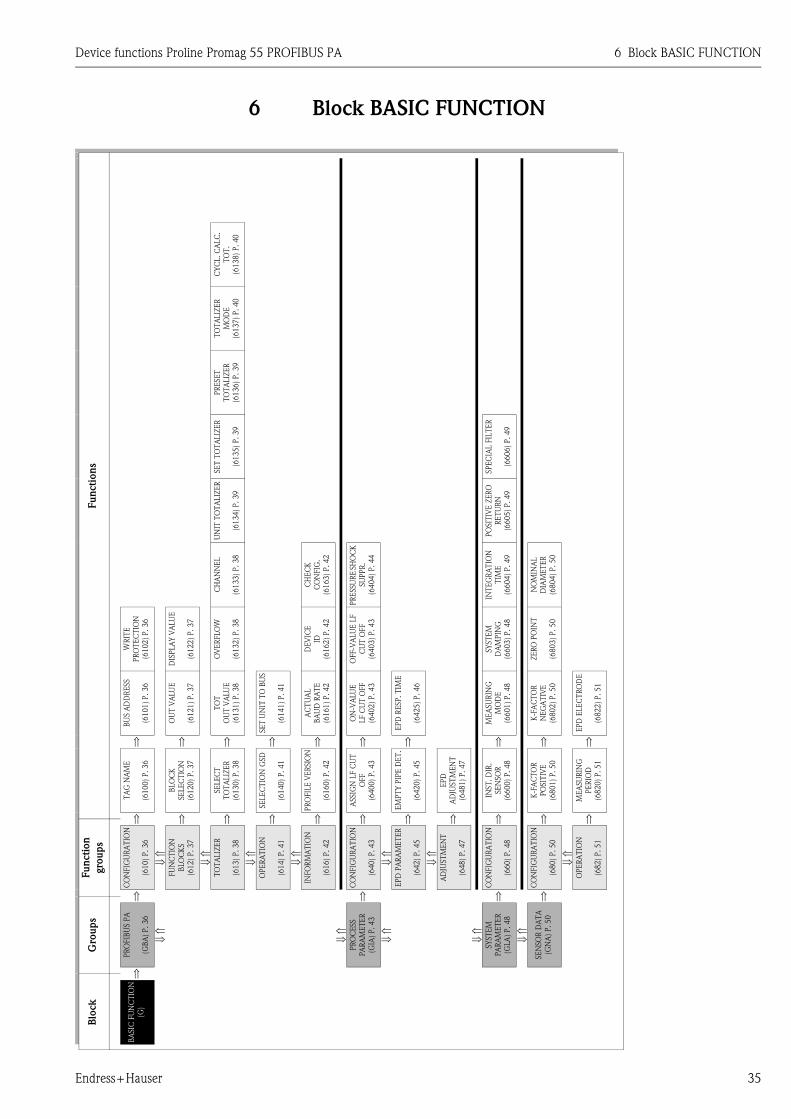
Endress+Hauser 35
6 Block BASIC FUNCTIONFu
ncti
on
s
CY
CL. C
ALC
.
TO
T.
(61
38
) P
.40
TO
TA
LIZ
ER
MO
DE
(61
37
) P
.4
0
PR
ESET
TO
TA
LIZ
ER
(61
36
) P
.3
9
SE
T T
OT
ALIZ
ER
(61
35
) P
.3
9
SPEC
IAL F
ILT
ER
(66
06
) P
.4
9
UN
IT T
OT
ALIZ
ER
(61
34
) P
.3
9
PO
SIT
IVE
ZER
O
RE
TU
RN
(66
05
) P
.4
9
CH
AN
NE
L
(61
33
) P
.3
8
CH
EC
K
CO
NFIG
.
(61
63
) P
.4
2
PR
ESSU
RE
SH
OC
K
SU
PPR
.
(64
04
) P
.4
4
INT
EG
RA
TIO
N
TIM
E
(66
04
) P
.4
9
NO
MIN
AL
DIA
ME
TE
R
(68
04
) P
.5
0
WR
ITE
PR
OT
EC
TIO
N
(61
02
) P
.3
6
DIS
PLA
Y V
ALU
E
(61
22
) P
.3
7
OV
ER
FLO
W
(61
32
) P
.3
8
DEV
ICE
ID
(61
62
) P
.4
2
OFF-V
ALU
E L
F
CU
T O
FF
(64
03
) P
.4
3
SY
ST
EM
DA
MPIN
G
(66
03
) P
.4
8
ZE
RO
PO
INT
(68
03
) P
.5
0
BU
S A
DD
RESS
(61
01
) P
.3
6
OU
T V
ALU
E
(61
21
) P
.3
7
TO
T
OU
T V
ALU
E
(61
31
) P
.3
8
SE
T U
NIT
TO
BU
S
(61
41
) P
.4
1
AC
TU
AL
BA
UD
RA
TE
(61
61
) P
.4
2
ON
-VA
LU
E
LF C
UT
OFF
(64
02
) P
.4
3
EP
D R
ESP
. T
IME
(64
25
) P
.4
6
ME
ASU
RIN
G
MO
DE
(66
01
) P
.4
8
K-F
AC
TO
R
NE
GA
TIV
E
(68
02
) P
.5
0
EPD
ELEC
TR
OD
E
(68
22
) P
.5
1
⇒ ⇒ ⇒ ⇒ ⇒ ⇒ ⇒ ⇒ ⇒ ⇒
TA
G N
AM
E
(61
00
) P
.3
6
BLO
CK
SE
LE
CT
ION
(61
20
) P
.3
7
SE
LE
CT
TO
TA
LIZ
ER
(61
30
) P
.3
8
SE
LE
CT
ION
GSD
(61
40
) P
.4
1
PR
OFIL
E V
ER
SIO
N
(61
60
) P
.4
2
ASSIG
N L
F C
UT
OFF
(64
00
) P
.4
3
EM
PT
Y P
IPE
DE
T.
(64
20
) P
.4
5
EP
D
AD
JUST
MEN
T
(64
81
) P
.4
7
INST
. D
IR.
SE
NSO
R
(66
00
) P
.4
8
K-F
AC
TO
R
PO
SIT
IVE
(68
01
) P
.5
0
MEA
SU
RIN
G
PE
RIO
D
(68
20
) P
.5
1
⇒ ⇒ ⇒ ⇒ ⇒ ⇒ ⇒ ⇒ ⇒ ⇒ ⇒
Fu
ncti
on
gro
up
s
CO
NFIG
UR
AT
ION
(61
0)
P.
36
⇓ ⇑
FU
NC
TIO
N
BLO
CK
S
(61
2)
P.
37
⇓ ⇑
TO
TA
LIZ
ER
(61
3)
P.
38
⇓ ⇑
OP
ER
AT
ION
(61
4)
P.
41
⇓ ⇑
INFO
RM
AT
ION
(61
6)
P.
42
CO
NFIG
UR
AT
ION
(64
0)
P.
43
⇓ ⇑
EP
D P
AR
AM
ET
ER
(64
2)
P.
45
⇓ ⇑
AD
JUST
ME
NT
(64
8)
P.
47
CO
NFIG
UR
AT
ION
(66
0)
P.
48
CO
NFIG
UR
AT
ION
(68
0)
P.
50
⇓ ⇑
OP
ER
AT
ION
(68
2)
P.
51
⇒ ⇒ ⇒ ⇒
Gro
up
s
PR
OFIB
US P
A
(GB
A)
P.3
6
⇓ ⇑
⇓ ⇑
PR
OC
ESS
PA
RA
ME
TE
R
(GIA
) P
.4
3
⇓ ⇑
⇓ ⇑
SY
ST
EM
PA
RA
ME
TE
R
(GLA
) P.48
⇓ ⇑
SE
NSO
R D
AT
A
(GN
A)
P.
50
⇒
Blo
ck
BA
SIC
FU
NC
TIO
N
(G)
6 Block BASIC FUNCTION Device functions Proline Promag 55 PROFIBUS PA
36 Endress+Hauser
6.1 Group PROFIBUS PA
6.1.1 Function group CONFIGURATION
BASIC FUNCTION G ⇒ PROFIBUS PA GCA ⇒ CONFIGURATION 610
Function description
BASIC FUNCTION → PROFIBUS PA → CONFIGURATION
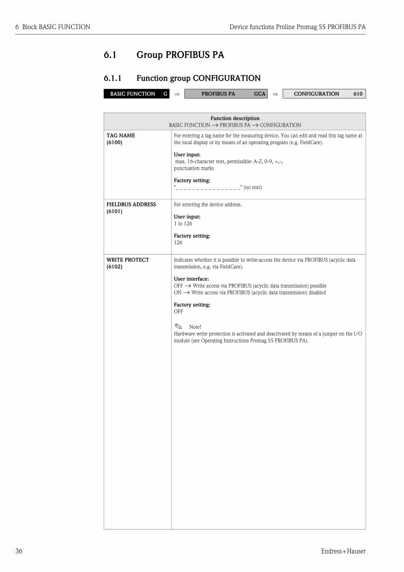
TAG NAME
(6100)
For entering a tag name for the measuring device. You can edit and read this tag name at
the local display or by means of an operating program (e.g. FieldCare).
User input:
max. 16-character text, permissible: A-Z, 0-9, +,-,
punctuation marks
Factory setting:
"_ _ _ _ _ _ _ _ _ _ _ _ _ _ _ _" (no text)
FIELDBUS ADDRESS
(6101)
For entering the device address.
User input:
1 to 126
Factory setting:
126
WRITE PROTECT
(6102)
Indicates whether it is possible to write-access the device via PROFIBUS (acyclic data
transmission, e.g. via FieldCare).
User interface:
OFF → Write access via PROFIBUS (acyclic data transmission) possible
ON → Write access via PROFIBUS (acyclic data transmission) disabled
Factory setting:
OFF
! Note!
Hardware write protection is activated and deactivated by means of a jumper on the I/O
module (see Operating Instructions Promag 55 PROFIBUS PA).

Device functions Proline Promag 55 PROFIBUS PA 6 Block BASIC FUNCTION
Endress+Hauser 37
6.1.2 Function group FUNCTION BLOCKS
BASIC FUNCTION G ⇒ PROFIBUS PA GCA ⇒ CONFIGURATION 610
⇓
FUNCTION BLOCKS 612
Function description
BASIC FUNCTION → PROFIBUS PA → FUNCTION BLOCKS
BLOCK SELECTION
(6120)
For selecting the PROFIBUS function block. If you select the Analog Input, the current
measured value is displayed in the OUT VALUE (6121) function. If the analog output is
selected, the current measured value is displayed in the DISPLAY VALUE function
(6122).
Options:
ANALOG INPUT 1
ANALOG INPUT 2
ANALOG OUTPUT 1
Factory setting:
ANALOG INPUT 1
! Note!
If PROFILE-GSD was selected in the SELECTION GSD (6140) function, only the
selection appears in this function:
• ANALOG INPUT 1
OUT VALUE
(6121) ! Note!
This function is not available unless one of the following was selected in the BLOCK
SELECTION (6120) function:
• ANALOG INPUT 1
• ANALOG INPUT 2
This function shows the measured variable (AI module), incl. unit and status, cyclically
transmitted to the PROFIBUS master (Class 1).
DISPLAY VALUE
(6122) ! Note!
This function is not available unless the ANALOG OUTPUT 1 option was selected in the
BLOCK SELECTION 6120 function.
This function shows the measured variable (DISPLAY_VALUE module), incl. unit and
status, cyclically transmitted from the PROFIBUS master (Class 1) to the measuring
device.
6 Block BASIC FUNCTION Device functions Proline Promag 55 PROFIBUS PA
38 Endress+Hauser
6.1.3 Function group TOTALIZER
BASIC FUNCTION G ⇒ PROFIBUS PA GCA ⇒ CONFIGURATION 610
⇓
FUNCTION BLOCKS 612
⇓
TOTALIZER 613
Function description
BASIC FUNCTION → PROFIBUS PA → TOTALIZER
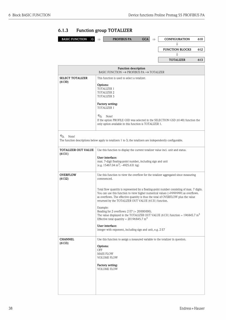
SELECT TOTALIZER
(6130)
This function is used to select a totalizer.
Options:
TOTALIZER 1
TOTALIZER 2
TOTALIZER 3
Factory setting:
TOTALIZER 1
! Note!
If the option PROFILE GSD was selected in the SELECTION GSD (6140) function the
only option available in this function is TOTALIZER 1.
! Note!
The function descriptions below apply to totalizers 1 to 3; the totalizers are independently configurable.
TOTALIZER OUT VALUE
(6131)
Use this function to display the current totalizer value incl. unit and status.
User interface:
max. 7-digit floating-point number, including sign and unit
(e.g. 15467.04 m3; –4925.631 kg)
OVERFLOW
(6132)
Use this function to view the overflow for the totalizer aggregated since measuring
commenced.
Total flow quantity is represented by a floating-point number consisting of max. 7 digits.
You can use this function to view higher numerical values (>9999999) as overflows.
as overflows. The effective quantity is thus the total of OVERFLOW plus the value
returned by the TOTALIZER OUT VALUE (6131) function.
Example:
Reading for 2 overflows: 2 E7 (= 20000000).
The value displayed in the TOTALIZER OUT VALUE (6131) function = 196845.7 m3
Effective total quantity = 20196845.7 m3
User interface:
integer with exponent, including sign and unit, e.g. 2 E7
CHANNEL
(6133)
Use this function to assign a measured variable to the totalizer in question.
Options:
OFF
MASS FLOW
VOLUME FLOW
Factory setting:
VOLUME FLOW

Device functions Proline Promag 55 PROFIBUS PA 6 Block BASIC FUNCTION
Endress+Hauser 39
UNIT
TOTALIZER
(6134)
Use this function to define the unit for the totalizer. The selection is dependent on the
measured variable selected in the CHANNEL (6133) function.
Options: (for VOLUME FLOW assignment):
Metric → cm3; dm3; m3; ml; l; hl; Ml Mega
US → ccc; af; ft3; oz f; gal; Kgal; Mgal; bbl (normal fluids); bbl (beer);
bbl (petrochemicals); bbl (filling tanks)
Imperial → gal; Mgal; bbl (beer); bbl (petrochemicals)
Factory setting:
m3
Options: (for MASS FLOW assignment):
Metric → g; kg; t
US → oz; lb; ton
Factory setting:
kg
SET TOTALIZER
(6135)
Use this function to assign a status to the totalizer.
Options:
TOTALIZE
The measured variable selected in the CHANNEL (6133) function is totalled.
RESET
Resets the totalizer to zero.
PRESET
Set the totalizer to the value defined in the PRESET TOTALIZER (6136) function.
! Note!
Note that selecting RESET or PRESET resets the totalizer to 0 or sets it to the preset value
respectively, but does not stop the totalizer. This means that it immediately recommences
totaling from the new setting. If you want to stop the totalizer you must select HOLD in
the TOTALIZER MODE (6137) function.
Factory setting:
TOTALIZE
PRESET TOTALIZER
(6136)
Use this function to define a start value for the totalizer.
This value is not accepted by the totalizer unless
the PRESET option has been selected in the SET TOTALIZER (6135) function.
User input:
–9999999 to 9999999
Factory setting:
0
Function description
BASIC FUNCTION → PROFIBUS PA → TOTALIZER

6 Block BASIC FUNCTION Device functions Proline Promag 55 PROFIBUS PA
40 Endress+Hauser
TOTALIZER MODE
(6137)
Use this function to define how the flow components are to be totalled by the totalizer.
Options:
BALANCE
Positive and negative flow components. The positive and negative flow components are
balanced. In other words, net flow in the flow direction is registered.
POSITIVE (forward)
Positive flow components only
NEGATIVE (backwards)
Negative flow components only
HOLD VALUE
The totalizer stops at the last value.
No further flow components are totaled.
Factory setting:
BALANCE
! Note!
For the calculation of the positive and negative flow components (BALANCE) or the
negative flow components only
(NEGATIVE) to be carried out correctly, the BIDIRECTIONAL option must be selected in
the MEASURING MODE function (6601) (s. Page 48).
CYCL. CALC. TOT.
(6138)
Use this function to define whether the totalizers 1 to 3 are updated on the local display
and in the operating program (e.g. FieldCare).
Options:
ON
Totalizers are always updated.
OFF
Totalizers are only updated if the corresponding totalizer function block (TOTAL module
or function) has been configured for cyclic data transmission.
Factory setting:
ON
! Note!
Especially when conducting time-critical applications, optimization can be carried out for
unnecessary totalizer function blocks. For this purpose, OFF must be selected in this
function. When doing this, ensure that the totalizer is no longer updated on the local
display and in the operating program (e.g. FieldCare) when selecting OFF.
Function description
BASIC FUNCTION → PROFIBUS PA → TOTALIZER

Device functions Proline Promag 55 PROFIBUS PA 6 Block BASIC FUNCTION
Endress+Hauser 41
6.1.4 Function group OPERATION
BASIC FUNCTION G ⇒ PROFIBUS PA GCA ⇒ CONFIGURATION 610
⇓
FUNCTION BLOCKS 612
⇓
TOTALIZER 613
⇓
OPERATION 614
Function description
BASIC FUNCTION → PROFIBUS PA → OPERATION
SELECTION GSD
(6140)
For selecting the operating mode (GSD file) which is used for the cyclic communication
with the PROFIBUS master (Class 1).
Options:
MANUFACT. SPEC. → the device is operated with the complete range of device
functionality.
MANUFACT V2.0 → the device is used as a replacement device for the previous model
Promag 35 (compatibility mode).
PROFILE GSD → the device is operated in PROFIBUS Profile mode.
Factory setting:
MANUFACT. SPEC.
! Note!
Ensure, when configuring the PROFIBUS network, that the dedicated Device Master File
(GSD file) of the measuring device is used for the selected operating mode (see Operating
Instructions Proline Promag 55 PROFIBUS PA).
SET UNIT TO BUS
(6141)
If this function is executed, the cyclically transmitted measured variables (AI module) are
transmitted to the PROFIBUS master (Class 1) with the system units set in the measuring
device.
Options:
OFF
SET UNITS (pressing the F button starts transmission)
" Caution!
Activating this function may result in a sudden change in the measured variables (module
AI) transferred to the PROFIBUS master (Class 1), which may in turn effect subsequent
adjustments.
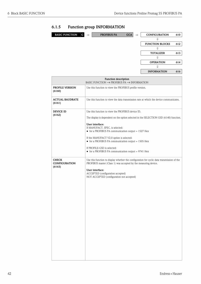
6 Block BASIC FUNCTION Device functions Proline Promag 55 PROFIBUS PA
42 Endress+Hauser
6.1.5 Function group INFORMATION
BASIC FUNCTION G ⇒ PROFIBUS PA GCA ⇒ CONFIGURATION 610
⇓
FUNCTION BLOCKS 612
⇓
TOTALIZER 613
⇓
OPERATION 614
⇓
INFORMATION 616
Function description
BASIC FUNCTION → PROFIBUS PA → INFORMATION
PROFILE VERSION
(6160)
Use this function to view the PROFIBUS profile version.
ACTUAL BAUDRATE
(6161)
Use this function to view the data transmission rate at which the device communicates.
DEVICE ID
(6162)
Use this function to view the PROFIBUS device ID.
The display is dependent on the option selected in the SELECTION GSD (6140) function.
User interface:
If MANUFACT. SPEC. is selected:
• for a PROFIBUS PA communication output = 1527 Hex
If the MANUFACT V2.0 option is selected:
• for a PROFIBUS PA communication output = 1505 Hex
If PROFILE-GSD is selected:
• for a PROFIBUS PA communication output = 9741 Hex
CHECK
CONFIGURATION
(6163)
Use this function to display whether the configuration for cyclic data transmission of the
PROFIBUS master (Class 1) was accepted by the measuring device.
User interface:
ACCEPTED (configuration accepted)
NOT ACCEPTED (configuration not accepted)
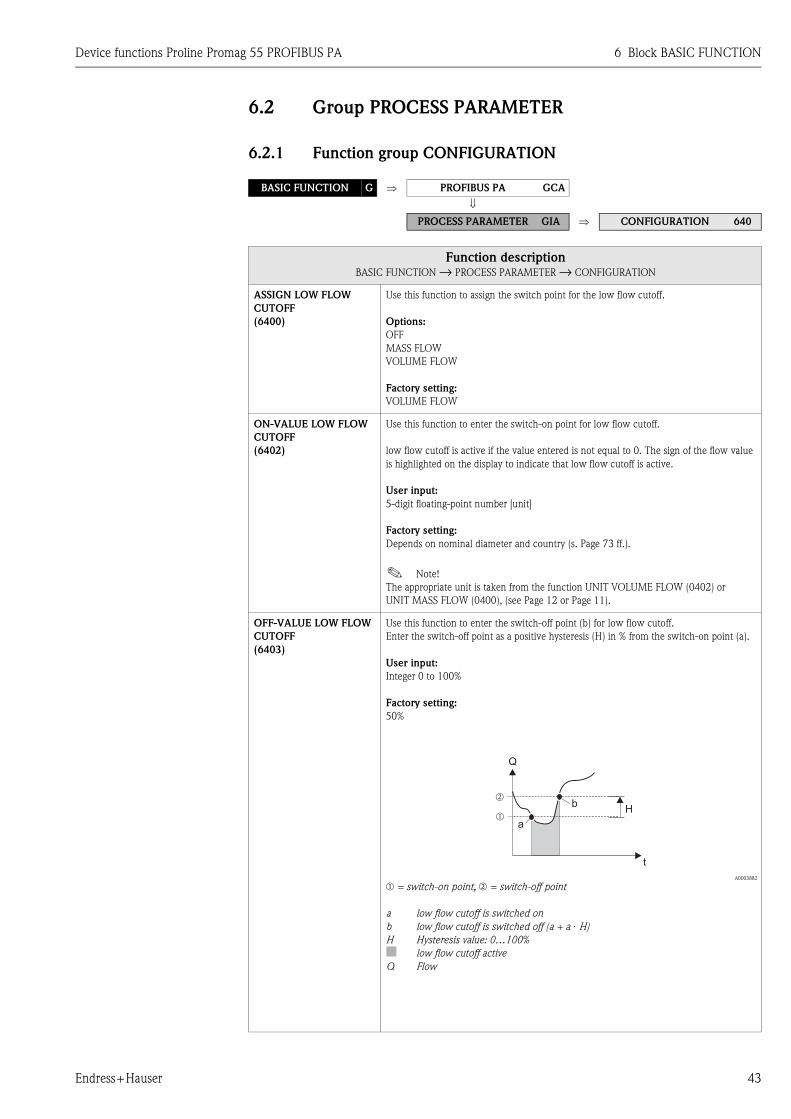
Device functions Proline Promag 55 PROFIBUS PA 6 Block BASIC FUNCTION
Endress+Hauser 43
6.2 Group PROCESS PARAMETER
6.2.1 Function group CONFIGURATION
BASIC FUNCTION G ⇒ PROFIBUS PA GCA
⇓ PROCESS PARAMETER GIA ⇒ CONFIGURATION 640
Function descriptionBASIC FUNCTION → PROCESS PARAMETER → CONFIGURATION
ASSIGN LOW FLOW
CUTOFF
(6400)
Use this function to assign the switch point for the low flow cutoff.
Options:
OFF
MASS FLOW
VOLUME FLOW
Factory setting:
VOLUME FLOW
ON-VALUE LOW FLOW
CUTOFF
(6402)
Use this function to enter the switch-on point for low flow cutoff.
low flow cutoff is active if the value entered is not equal to 0. The sign of the flow value
is highlighted on the display to indicate that low flow cutoff is active.
User input:
5-digit floating-point number [unit]
Factory setting:
Depends on nominal diameter and country (s. Page 73 ff.).
! Note!
The appropriate unit is taken from the function UNIT VOLUME FLOW (0402) or
UNIT MASS FLOW (0400), (see Page 12 or Page 11).
OFF-VALUE LOW FLOW
CUTOFF
(6403)
Use this function to enter the switch-off point (b) for low flow cutoff.
Enter the switch-off point as a positive hysteresis (H) in % from the switch-on point (a).
User input:
Integer 0 to 100%
Factory setting:
50%
A0003882
m = switch-on point, n = switch-off point
a low flow cutoff is switched on
b low flow cutoff is switched off (a + a ⋅ H)
H Hysteresis value: 0…100%
■ low flow cutoff active
Q Flow
t
H
Q
m
nb
a

6 Block BASIC FUNCTION Device functions Proline Promag 55 PROFIBUS PA
44 Endress+Hauser
PRESSURE SHOCK
SUPPRESSION
(6404)
The closure of a valve can cause brief but severe movements of the fluid in the piping
system, movements which the measuring system registers. The pulses totalled in this way
result in a totalizer reading error, particularly in the case of batching processes. For this
reason, the measuring device is equipped with pressure shock suppression (= short-term
signal suppression) which can eliminate system-related "disruptions".
! Note!
Note that pressure shock suppression cannot be used unless the low flow cutoff is active
(see ON-VALUE LOW FLOW CUT OFF function on Page 43).
Use this function to define the time span for active pressure shock suppression.
Activation of the pressure shock suppression
Pressure shock suppression is activated once the flow falls below the switch-on point of
the low flow (see point a in graphic).
While pressure shock suppression is active, the following conditions apply:
• Flow reading on display → 0
• Totalizer reading → the totalizers are pegged at the last correct value.
Deactivation of the pressure shock suppression
The pressure shock suppression is deactivated after the time interval, set in this function,
has passed (see point b in graphic).
! Note!
The actual flow value is displayed and output, when the time interval for the pressure
shock suppression has passed and the flow exceeds the switch-off point of the low flow
(see point c in graphic).
A0001285-EN
m = switsch-off point (low flow ), n = switch-on point (low flow )
a Activated if on-value of low flow is not reached
b Deactivated once the predefined time period has elapsed
c Flow values are taken into account when calculating the pulses
■ Suppressed values
Q Flow
User input:
max. 4-digit number, incl. unit: 0.00 to 100.0 s
Factory setting:
0.00 s
Function descriptionBASIC FUNCTION → PROCESS PARAMETER → CONFIGURATION
nm
a b c
inactive active inactive
t
Pressure shock suppression
Command:Valve closes
Q
Given time
After filling
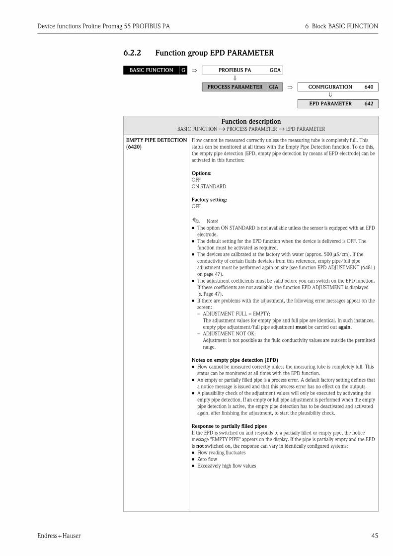
Device functions Proline Promag 55 PROFIBUS PA 6 Block BASIC FUNCTION
Endress+Hauser 45
6.2.2 Function group EPD PARAMETER
BASIC FUNCTION G ⇒ PROFIBUS PA GCA
⇓ PROCESS PARAMETER GIA ⇒ CONFIGURATION 640
⇓ EPD PARAMETER 642
Function descriptionBASIC FUNCTION → PROCESS PARAMETER → EPD PARAMETER
EMPTY PIPE DETECTION
(6420)
Flow cannot be measured correctly unless the measuring tube is completely full. This
status can be monitored at all times with the Empty Pipe Detection function. To do this,
the empty pipe detection (EPD, empty pipe detection by means of EPD electrode) can be
activated in this function:
Options:
OFF
ON STANDARD
Factory setting:
OFF
! Note!
• The option ON STANDARD is not available unless the sensor is equipped with an EPD
electrode.
• The default setting for the EPD function when the device is delivered is OFF. The
function must be activated as required.
• The devices are calibrated at the factory with water (approx. 500 μS/cm). If the
conductivity of certain fluids deviates from this reference, empty pipe/full pipe
adjustment must be performed again on site (see function EPD ADJUSTMENT (6481)
on page 47).
• The adjustment coefficients must be valid before you can switch on the EPD function.
If these coefficients are not available, the function EPD ADJUSTMENT is displayed
(s. Page 47).
• If there are problems with the adjustment, the following error messages appear on the
screen:
– ADJUSTMENT FULL = EMPTY:
The adjustment values for empty pipe and full pipe are identical. In such instances,
empty pipe adjustment/full pipe adjustment must be carried out again.
– ADJUSTMENT NOT OK:
Adjustment is not possible as the fluid conductivity values are outside the permitted
range.
Notes on empty pipe detection (EPD)
• Flow cannot be measured correctly unless the measuring tube is completely full. This
status can be monitored at all times with the EPD function.
• An empty or partially filled pipe is a process error. A default factory setting defines that
a notice message is issued and that this process error has no effect on the outputs.
• A plausibility check of the adjustment values will only be executed by activating the
empty pipe detection. If an empty or full pipe adjustment is performed when the empty
pipe detection is active, the empty pipe detection has to be deactivated and activated
again, after finishing the adjustment, to start the plausibility check.
Response to partially filled pipes
If the EPD is switched on and responds to a partially filled or empty pipe, the notice
message "EMPTY PIPE" appears on the display. If the pipe is partially empty and the EPD
is not switched on, the response can vary in identically configured systems:
• Flow reading fluctuates
• Zero flow
• Excessively high flow values

6 Block BASIC FUNCTION Device functions Proline Promag 55 PROFIBUS PA
46 Endress+Hauser
EPD RESPONSE TIME
(6425) ! Note!
The function is only available if the function EMPTY PIPE DET. (6420) has been
switched on.
Use this function to enter the time span for which the criteria for an "empty" pipe have to
be satisfied without interruption before a notice message or fault message is generated.
User input:
fixed point number: 1.0 to 100 s
Factory setting:
1.0 s
Function descriptionBASIC FUNCTION → PROCESS PARAMETER → EPD PARAMETER
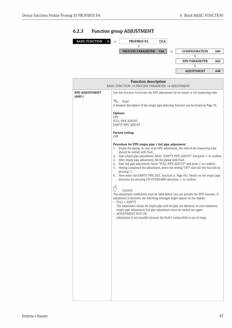
Device functions Proline Promag 55 PROFIBUS PA 6 Block BASIC FUNCTION
Endress+Hauser 47
6.2.3 Function group ADJUSTMENT
BASIC FUNCTION G ⇒ PROFIBUS PA GCA
⇓ PROCESS PARAMETER GIA ⇒ CONFIGURATION 640
⇓
EPD PARAMETER 642
⇓ ADJUSTMENT 648
Function descriptionBASIC FUNCTION → PROCESS PARAMETER → ADJUSTMENT
EPD ADJUSTMENT
(6481)
Use this function to activate the EPD adjustment for an empty or full measuring tube.
! Note!
A detailed description of the empty pipe detection function can be found on Page 45.
Options:
OFF
FULL PIPE ADJUST
EMPTY PIPE ADJUST
Factory setting:
OFF
Procedure for EPD empty pipe / full pipe adjustment
1. Empty the piping. In case of an EPD adjustment, the wall of the measuring tube
should be wetted with fluid.
2. Start empty pipe adjustment: Select "EMPTY PIPE ADJUST" and press F to confirm.
3. After empty pipe adjustment, fill the piping with fluid.
4. Start full pipe adjustment: Select "FULL PIPE ADJUST" and press F to confirm.
5. Having completed the adjustment, select the setting "OFF" and exit the function by
pressing F .
6. Now select the EMPTY PIPE DET. function (s. Page 45). Switch on the empty pipe
detection by selecting ON STANDARD and press F to confirm.
" Caution!
The adjustment coefficients must be valid before you can activate the EPD function. If
adjustment is incorrect the following messages might appear on the display:
– FULL = EMPTY
The adjustment values for empty pipe and full pipe are identical. In such instances,
empty pipe adjustment/full pipe adjustment must be carried out again.
– ADJUSTMENT NOT OK
Adjustment is not possible because the fluid’s conductivity is out of range.
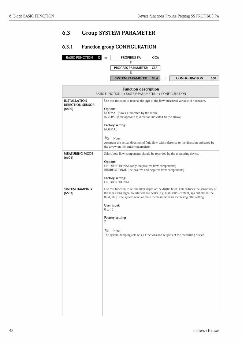
6 Block BASIC FUNCTION Device functions Proline Promag 55 PROFIBUS PA
48 Endress+Hauser
6.3 Group SYSTEM PARAMETER
6.3.1 Function group CONFIGURATION
BASIC FUNCTION G ⇒ PROFIBUS PA GCA
⇓ PROCESS PARAMETER GIA
⇓ SYSTEM PARAMETER GLA ⇒ CONFIGURATION 660
Function descriptionBASIC FUNCTION → SYSTEM PARAMETER → CONFIGURATION
INSTALLATION
DIRECTION SENSOR
(6600)
Use this function to reverse the sign of the flow measured variable, if necessary.
Options:
NORMAL (flow as indicated by the arrow)
INVERSE (flow opposite to direction indicated by the arrow)
Factory setting:
NORMAL
! Note!
Ascertain the actual direction of fluid flow with reference to the direction indicated by
the arrow on the sensor (nameplate).
MEASURING MODE
(6601)
Select how flow components should be recorded by the measuring device.
Options:
UNIDIRECTIONAL (only the positive flow components)
BIDIRECTIONAL (the positive and negative flow components)
Factory setting:
UNIDIRECTIONAL
SYSTEM DAMPING
(6603)
Use this function to set the filter depth of the digital filter. This reduces the sensitivity of
the measuring signal to interference peaks (e.g. high solids content, gas bubbles in the
fluid, etc.). The system reaction time increases with an increasing filter setting.
User input:
0 to 15
Factory setting:
7
! Note!
The system damping acts on all functions and outputs of the measuring device.
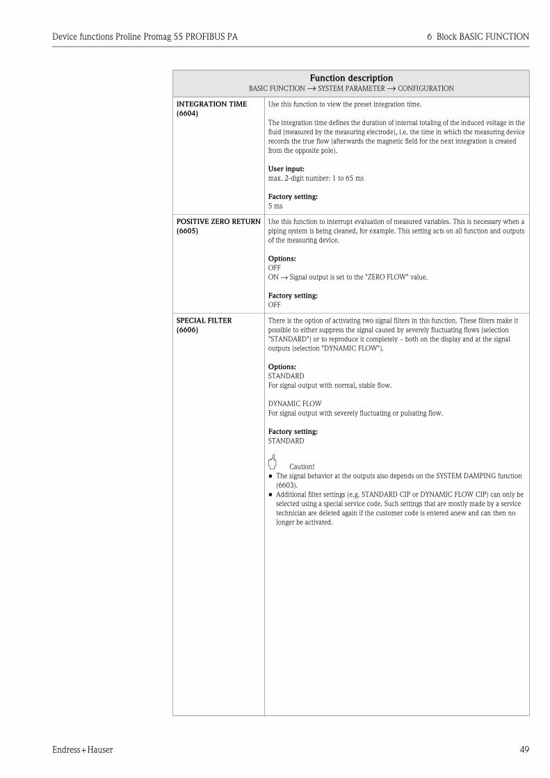
Device functions Proline Promag 55 PROFIBUS PA 6 Block BASIC FUNCTION
Endress+Hauser 49
INTEGRATION TIME
(6604)
Use this function to view the preset integration time.
The integration time defines the duration of internal totaling of the induced voltage in the
fluid (measured by the measuring electrode), i.e. the time in which the measuring device
records the true flow (afterwards the magnetic field for the next integration is created
from the opposite pole).
User input:
max. 2-digit number: 1 to 65 ms
Factory setting:
5 ms
POSITIVE ZERO RETURN
(6605)
Use this function to interrupt evaluation of measured variables. This is necessary when a
piping system is being cleaned, for example. This setting acts on all function and outputs
of the measuring device.
Options:
OFF
ON → Signal output is set to the "ZERO FLOW" value.
Factory setting:
OFF
SPECIAL FILTER
(6606)
There is the option of activating two signal filters in this function. These filters make it
possible to either suppress the signal caused by severely fluctuating flows (selection
"STANDARD") or to reproduce it completely – both on the display and at the signal
outputs (selection "DYNAMIC FLOW").
Options:
STANDARD
For signal output with normal, stable flow.
DYNAMIC FLOW
For signal output with severely fluctuating or pulsating flow.
Factory setting:
STANDARD
" Caution!
• The signal behavior at the outputs also depends on the SYSTEM DAMPING function
(6603).
• Additional filter settings (e.g. STANDARD CIP or DYNAMIC FLOW CIP) can only be
selected using a special service code. Such settings that are mostly made by a service
technician are deleted again if the customer code is entered anew and can then no
longer be activated.
Function descriptionBASIC FUNCTION → SYSTEM PARAMETER → CONFIGURATION

6 Block BASIC FUNCTION Device functions Proline Promag 55 PROFIBUS PA
50 Endress+Hauser
6.4 Group SENSOR DATA
6.4.1 Function group CONFIGURATION
BASIC FUNCTION G ⇒ PROFIBUS PA GCA
⇓ PROCESS PARAMETER GIA
⇓ SYSTEM PARAMETER GLA
⇓ SENSOR DATA GNA ⇒ CONFIGURATION 680
Function descriptionBASIC FUNCTION → SENSOR DATA → CONFIGURATION
All sensor data (calibration factors, zero (point) and nominal diameter) are set at the factory and saved on the S-DAT
sensor memory chip.
! Note!
The individual values of the functions are also provided on the sensor nameplate.
" Caution!
Under normal circumstances you should not change the following parameter settings, because changes affect numerous
functions of the entire measuring facility in general and the accuracy of the measuring system in particular. For this
reason, the functions described below cannot be changed even when you enter your personal code.
Contact the Endress+Hauser service organization if you have any questions about these functions.
K-FACTOR POSITIVE
(6801)
Use this function to display the current calibration factor (positive flow direction) for the
sensor. The calibration factor is determined and set at the factory.
User interface:
5-digit fixed point number: 0.5000 to 2.0000
Factory setting:
Depends on nominal diameter and calibration
K-FACTOR NEGATIVE
(6802)
Use this function to display the current calibration factor (negative flow direction) for the
sensor. The calibration factor is determined and set at the factory.
User interface:
5-digit fixed point number: 0.5000 to 2.0000
Factory setting:
Depends on nominal diameter and calibration
ZERO POINT
(6803)
Use this function to view the current zero-point correction value for the sensor.
Zero-point correction is determined and set at the factory.
User interface:
max. 4-digit number: –1000 to +1000
Factory setting:
Depends on nominal diameter and calibration
NOMINAL DIAMETER
(6804)
Use this function to view the nominal diameter of the sensor. The nominal diameter
depends on the size of the sensor and is set at the factory.
User interface:
2 to 2000 mm or 1/12 to 78"
Factory setting:
Depends on the size of the sensor

Device functions Proline Promag 55 PROFIBUS PA 6 Block BASIC FUNCTION
Endress+Hauser 51
6.4.2 Function group OPERATION
BASIC FUNCTION G ⇒ PROFIBUS PA GCA
⇓
PROCESS PARAMETER GIA
⇓ SYSTEM PARAMETER GLA
⇓ SENSOR DATA GNA ⇒ CONFIGURATION 680
⇓ OPERATION 682
Function descriptionBASIC FUNCTION → SENSOR DATA → OPERATION
"All sensor data (measuring period, overvoltage time, etc.) are set at the factory and saved on the S-DAT sensor memory chip.
" Caution!
Under normal circumstances you should not change the following parameter settings, because changes affect numerous
functions of the entire measuring facility in general and the accuracy of the measuring system in particular. For this
reason, the functions described below cannot be changed even when you enter your personal code.
Contact the Endress+Hauser service organization if you have any questions about these functions.
MEASURING PERIOD
(6820)
Use this function to view the time for a full measuring period. The duration of the
measuring period is calculated from the rise time of the magnetic field, the brief recovery
time, the integration time and the empty pipe detection time.
User input:
max. 4-digit number: 10 to 1000 ms
Factory setting:
Depends on nominal diameter
EPD ELECTRODE
(6822)
Use this function to check whether the sensor is equipped with an EPD electrode.
User interface:
YES
NO
Factory setting:
YES → Electrode fitted as standard
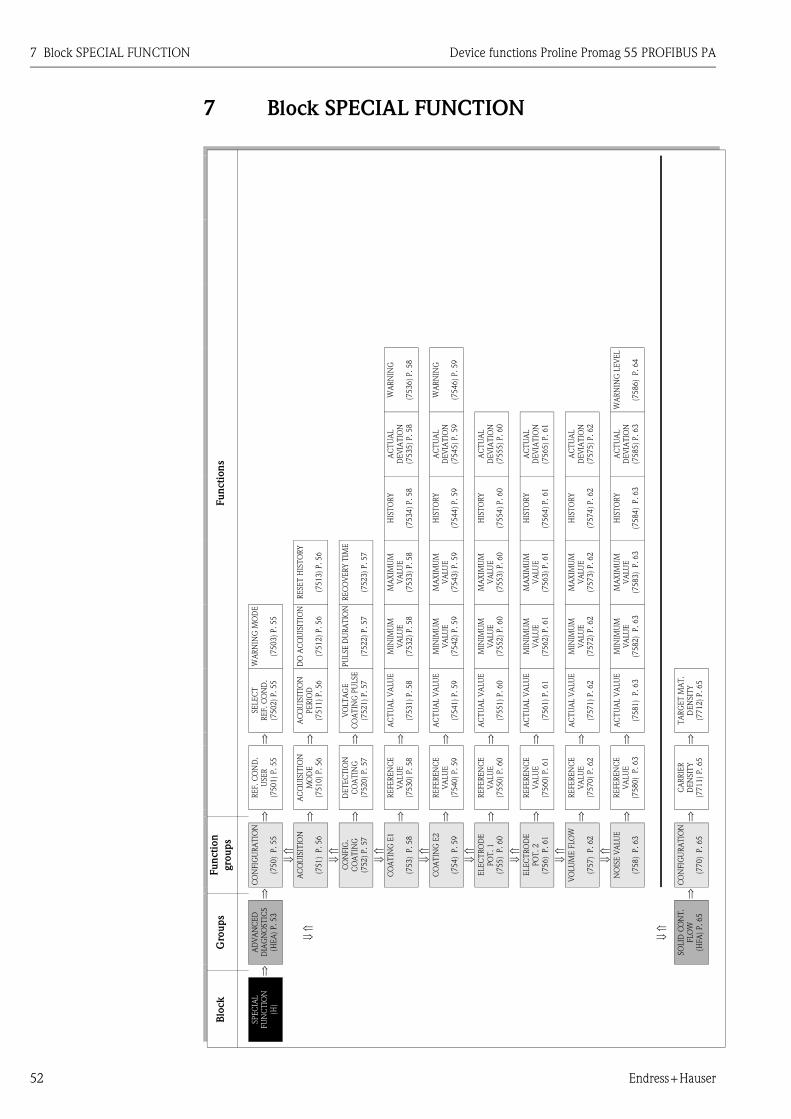
7 Block SPECIAL FUNCTION Device functions Proline Promag 55 PROFIBUS PA
52 Endress+Hauser
7 Block SPECIAL FUNCTION
Fu
ncti
on
s
WA
RN
ING
(75
36
) P
.5
8
WA
RN
ING
(75
46
) P
.5
9
WA
RN
ING
LE
VEL
(75
86
) P
.6
4
AC
TU
AL
DE
VIA
TIO
N
(75
35
) P
.5
8
AC
TU
AL
DE
VIA
TIO
N
(75
45
) P
.5
9
AC
TU
AL
DE
VIA
TIO
N
(75
55
) P
.6
0
AC
TU
AL
DE
VIA
TIO
N
(75
65
) P
.6
1
AC
TU
AL
DE
VIA
TIO
N
(75
75
) P
.6
2
AC
TU
AL
DE
VIA
TIO
N
(75
85
) P
.6
3
HIS
TO
RY
(75
34
) P
.5
8
HIS
TO
RY
(75
44
) P
.5
9
HIS
TO
RY
(75
54
) P
.6
0
HIS
TO
RY
(75
64
) P
.6
1
HIS
TO
RY
(75
74
) P
.6
2
HIS
TO
RY
(75
84
) P
.6
3
RE
SE
T H
IST
OR
Y
(75
13
) P
.5
6
RE
CO
VE
RY
TIM
E
(75
23
) P
.5
7
MA
XIM
UM
VA
LU
E
(75
33
) P
.5
8
MA
XIM
UM
VA
LU
E
(75
43
) P
.5
9
MA
XIM
UM
VA
LU
E
(75
53
) P
.6
0
MA
XIM
UM
VA
LU
E
(75
63
) P
.6
1
MA
XIM
UM
VA
LU
E
(75
73
) P
.6
2
MA
XIM
UM
VA
LU
E
(75
83
) P
.6
3
WA
RN
ING
MO
DE
(75
03
) P
.5
5
DO
AC
QU
ISIT
ION
(75
12
) P
.5
6
PU
LSE
DU
RA
TIO
N
(75
22
) P
.5
7
MIN
IMU
M
VA
LU
E
(75
32
) P
.5
8
MIN
IMU
M
VA
LU
E
(75
42
) P
.5
9
MIN
IMU
M
VA
LU
E
(75
52
) P
.6
0
MIN
IMU
M
VA
LU
E
(75
62
) P
.6
1
MIN
IMU
M
VA
LU
E
(75
72
) P
.6
2
MIN
IMU
M
VA
LU
E
(7582)
P.63
SE
LE
CT
RE
F. C
ON
D.
(75
02
) P
.5
5
AC
QU
ISIT
ION
PE
RIO
D
(75
11
) P
.5
6
VO
LT
AG
E
CO
AT
ING
PU
LSE
(75
21
) P
.5
7
AC
TU
AL V
ALU
E
(75
31
) P
.5
8
AC
TU
AL V
ALU
E
(75
41
) P
.5
9
AC
TU
AL V
ALU
E
(75
51
) P
.6
0
AC
TU
AL V
ALU
E
(75
61
) P
.6
1
AC
TU
AL V
ALU
E
(75
71
) P
.6
2
AC
TU
AL V
ALU
E
(75
81
) P
.6
3
TA
RG
ET
MA
T.
DE
NSIT
Y
(77
12
) P
.6
5
⇒ ⇒ ⇒ ⇒ ⇒ ⇒ ⇒ ⇒ ⇒ ⇒
RE
F.
CO
ND
.
USE
R
(75
01
) P
.5
5
AC
QU
ISIT
ION
MO
DE
(75
10
) P
.5
6
DE
TE
CT
ION
CO
AT
ING
(75
20
) P
.5
7
RE
FE
RE
NC
E
VA
LU
E
(75
30
) P
.5
8
RE
FE
RE
NC
E
VA
LU
E
(75
40
) P
.5
9
RE
FE
RE
NC
E
VA
LU
E
(75
50
) P
.6
0
RE
FE
RE
NC
E
VA
LU
E
(75
60
) P
.6
1
RE
FE
RE
NC
E
VA
LU
E
(75
70
) P
.6
2
RE
FE
RE
NC
E
VA
LU
E
(75
80
) P
.6
3
CA
RR
IER
DE
NSIT
Y
(77
11
) P
.6
5
⇒ ⇒ ⇒ ⇒ ⇒ ⇒ ⇒ ⇒ ⇒ ⇒
Fu
nct
ion
gro
up
s
CO
NFIG
UR
AT
ION
(75
0)
P.5
5
⇓ ⇑
AC
QU
ISIT
ION
(75
1)
P.5
6
⇓ ⇑
CO
NFIG
.
CO
AT
ING
(75
2)
P.57
⇓ ⇑
CO
AT
ING
E1
(75
3)
P.5
8
⇓ ⇑
CO
AT
ING
E2
(75
4)
P.5
9
⇓ ⇑
ELEC
TR
OD
E
PO
T. 1
(75
5)
P.6
0
⇓ ⇑
ELEC
TR
OD
E
PO
T. 2
(75
6)
P.6
1
⇓ ⇑
VO
LU
ME
FLO
W
(75
7)
P.6
2
⇓ ⇑
NO
ISE
VA
LU
E
(75
8)
P.6
3
CO
NFIG
UR
AT
ION
(77
0)
P.6
5
⇒ ⇒
Gro
up
s
AD
VA
NC
ED
DIA
GN
OST
ICS
(HE
A)
P.5
3
⇓ ⇑
⇓ ⇑
SO
LID
CO
NT
.
FLO
W
(HFA
) P
.6
5
⇒
Blo
ck
SP
EC
IAL
FU
NC
TIO
N
(H)
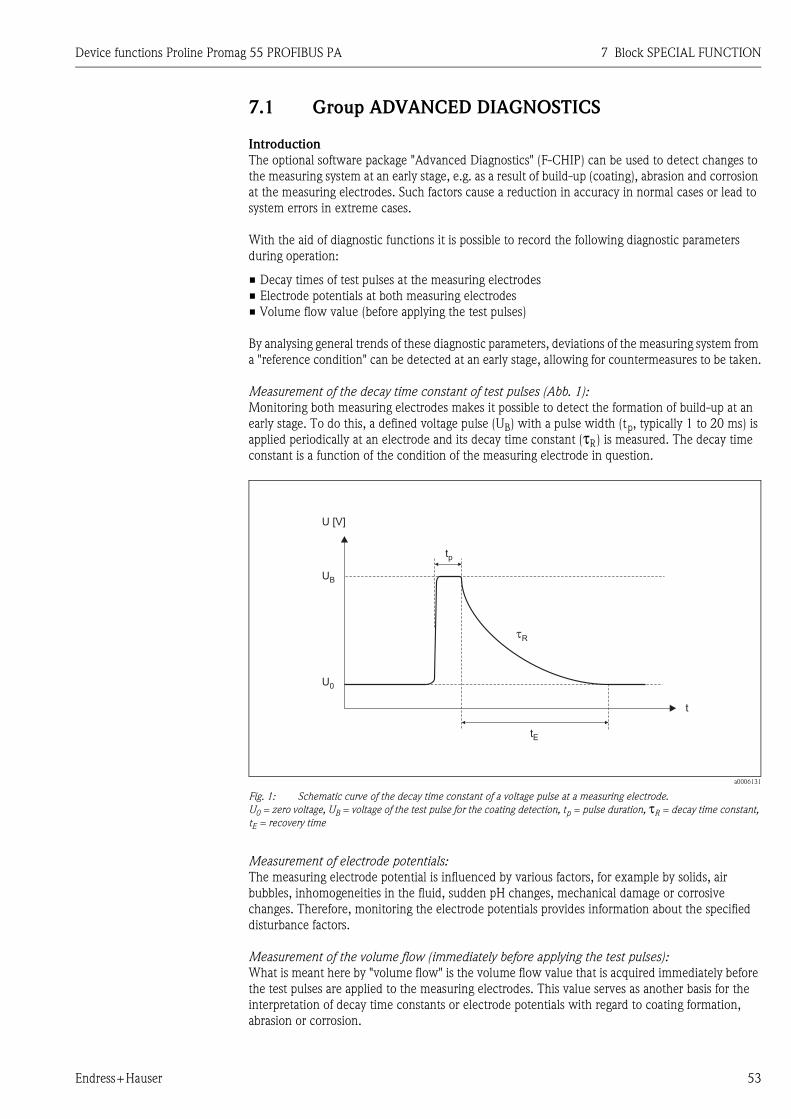
Device functions Proline Promag 55 PROFIBUS PA 7 Block SPECIAL FUNCTION
Endress+Hauser 53
7.1 Group ADVANCED DIAGNOSTICS
Introduction
The optional software package "Advanced Diagnostics" (F-CHIP) can be used to detect changes to
the measuring system at an early stage, e.g. as a result of build-up (coating), abrasion and corrosion
at the measuring electrodes. Such factors cause a reduction in accuracy in normal cases or lead to
system errors in extreme cases.
With the aid of diagnostic functions it is possible to record the following diagnostic parameters
during operation:
• Decay times of test pulses at the measuring electrodes
• Electrode potentials at both measuring electrodes
• Volume flow value (before applying the test pulses)
By analysing general trends of these diagnostic parameters, deviations of the measuring system from
a "reference condition" can be detected at an early stage, allowing for countermeasures to be taken.
Measurement of the decay time constant of test pulses (Abb. 1):
Monitoring both measuring electrodes makes it possible to detect the formation of build-up at an
early stage. To do this, a defined voltage pulse (UB) with a pulse width (tp, typically 1 to 20 ms) is
applied periodically at an electrode and its decay time constant (τR) is measured. The decay time
constant is a function of the condition of the measuring electrode in question.
a0006131
Fig. 1: Schematic curve of the decay time constant of a voltage pulse at a measuring electrode.
U0 = zero voltage, UB = voltage of the test pulse for the coating detection, tp = pulse duration, τR = decay time constant,
tE = recovery time
Measurement of electrode potentials:
The measuring electrode potential is influenced by various factors, for example by solids, air
bubbles, inhomogeneities in the fluid, sudden pH changes, mechanical damage or corrosive
changes. Therefore, monitoring the electrode potentials provides information about the specified
disturbance factors.
Measurement of the volume flow (immediately before applying the test pulses):
What is meant here by "volume flow" is the volume flow value that is acquired immediately before
the test pulses are applied to the measuring electrodes. This value serves as another basis for the
interpretation of decay time constants or electrode potentials with regard to coating formation,
abrasion or corrosion.
U [V]
UB
tp
�R
tE
t
U0
7 Block SPECIAL FUNCTION Device functions Proline Promag 55 PROFIBUS PA
54 Endress+Hauser
Activating coating detection (procedure)
1. Ascertain reference values for the diagnostic parameters → Function REFERENCE
CONDITION USER (7501).
2. Select reference condition → Function SELECT REFERENCE CONDITION (7502)
3. Specify when and how the diagnostic parameter values are to be ascertained:
– Time intervals → Function ACQUISITION PERIOD (7511)
– Periodical or manual → Function ACQUISITION MODE (7510)
4. Switch on coating detection → Function DETECTION COATING (7520)
5. Activate warning mode (if desired):
! Note!
Activating the WARNING MODE (7503) function normally only makes sense if a trend
analysis of the diagnostic parameter values in question has been performed beforehand! Only
then, can process-specific limit values be entered (= max. permitted deviation from the
reference status).
– Switch on warning mode → Function WARNING MODE (7503)
– Enter the maximum permitted deviation of the decay time constant from the reference
condition → Function WARNING (7536, 7546)
Trend analysis of diagnostic parameters
By evaluating a sufficiently large number of measuring values, useful trend information can be
acquired that provides information about possible coating formations or damage to the measuring
electrodes - for example, as a result of corrosion or mechanical influences.
The following values of diagnostic parameters can be called up via the function matrix:
• Reference values
• Actual values of the decay time constant or of the electrode potential
• Minimum/maximum values since the last adjustment
• Data history of the last 10 measuring values (or 100 values when interrogating via the "FieldCare"
software)
• Actual deviation between diagnostic parameter value and reference value
To assess possible build-up, the diagnostic parameters of the COATING 1 and COATING 2 function
groups should only be interpreted and assessed in combination with those of ELECTRODE
POTENTIAL 1/2 and VOLUME FLOW parameters. As build-up typically develops over a period of
months, it is useful to present and analyze the relevant measured data and parameters using
appropriate software, for example, the Endress+Hauser software package "FieldCare".
" Caution!
Since the decay time and the electrode potential are dependent on the process conditions at the
electrode and, therefore, on the fluid, a new reference measurement is required as the starting point
for a trend analysis for each process and each fluid in a balanced state. The measuring values are
then measured periodically and saved in the device storage unit (RAM).
! Note!
More information about "trend analysis" can be found in the Operating Instructions for this
measuring device.
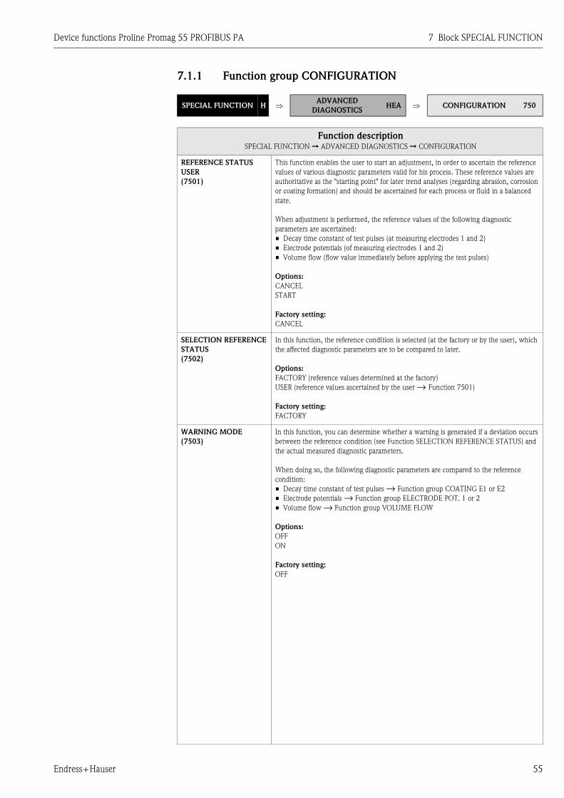
Device functions Proline Promag 55 PROFIBUS PA 7 Block SPECIAL FUNCTION
Endress+Hauser 55
7.1.1 Function group CONFIGURATION
SPECIAL FUNCTION H ⇒ADVANCED
DIAGNOSTICSHEA ⇒ CONFIGURATION 750
Function descriptionSPECIAL FUNCTION ➞ ADVANCED DIAGNOSTICS ➞ CONFIGURATION
REFERENCE STATUS
USER
(7501)
This function enables the user to start an adjustment, in order to ascertain the reference
values of various diagnostic parameters valid for his process. These reference values are
authoritative as the "starting point" for later trend analyses (regarding abrasion, corrosion
or coating formation) and should be ascertained for each process or fluid in a balanced
state.
When adjustment is performed, the reference values of the following diagnostic
parameters are ascertained:
• Decay time constant of test pulses (at measuring electrodes 1 and 2)
• Electrode potentials (of measuring electrodes 1 and 2)
• Volume flow (flow value immediately before applying the test pulses)
Options:
CANCEL
START
Factory setting:
CANCEL
SELECTION REFERENCE
STATUS
(7502)
In this function, the reference condition is selected (at the factory or by the user), which
the affected diagnostic parameters are to be compared to later.
Options:
FACTORY (reference values determined at the factory)
USER (reference values ascertained by the user → Function 7501)
Factory setting:
FACTORY
WARNING MODE
(7503)
In this function, you can determine whether a warning is generated if a deviation occurs
between the reference condition (see Function SELECTION REFERENCE STATUS) and
the actual measured diagnostic parameters.
When doing so, the following diagnostic parameters are compared to the reference
condition:
• Decay time constant of test pulses → Function group COATING E1 or E2
• Electrode potentials → Function group ELECTRODE POT. 1 or 2
• Volume flow → Function group VOLUME FLOW
Options:
OFF
ON
Factory setting:
OFF

7 Block SPECIAL FUNCTION Device functions Proline Promag 55 PROFIBUS PA
56 Endress+Hauser
7.1.2 Function group ACQUISITION
SPECIAL FUNCTION H ⇒ADVANCED
DIAGNOSTICSHEA ⇒ CONFIGURATION 750
⇓ ACQUISITION 751
Function descriptionSPECIAL FUNCTION ➞ ADVANCED DIAGNOSTICS ➞ ACQUISITION
ACQUISITION MODE
(7510)
In this function, you define whether the diagnostic parameters are acquired periodically
by the measuring device or manually by the user.
Options:
OFF
PERIODICAL
SINGLE SHOT
Factory setting:
OFF
ACQUISITION PERIOD
(7511) ! Note!
This function is not available unless the "PERIODICAL" setting was selected in the
ACQUISITION MODE function (7510).
In this function, a time interval is specified that is used to acquire and record the affected
diagnostic parameters periodically. This function is active as soon as the input is
confirmed with the F key.
User input:
10 to 10 080 min
Factory setting:
60 min
! Note!
A defined reference condition must be present before the diagnostic parameters are
measured → see Function SELECTION REFERENCE STATUS (7502).
DO ACQUISITION
(7512) ! Note!
This function is not available unless the "SINGLE SHOT" setting was selected in the
ACQUISITION MODE function (7510).
This function can be used to start the test measurements of diagnostic parameters
manually, e.g. sporadically depending on the process conditions.
Options:
CANCEL
START
Factory setting:
CANCEL
! Note!
A defined reference condition must be present before the diagnostic parameters are
acquired → see Function SELECTION REFERENCE STATUS (7502).
RESET HISTORY
(7513)
All previously saved diagnostic parameter values can be deleted with this function (=
parameters of the COATING E1, COATING E2, ELECTRODE POTENTIAL 1,
ELECTRODE POTENTIAL 2 and VOLUME FLOW function groups).
Options:
NO
YES
Factory setting:
NO
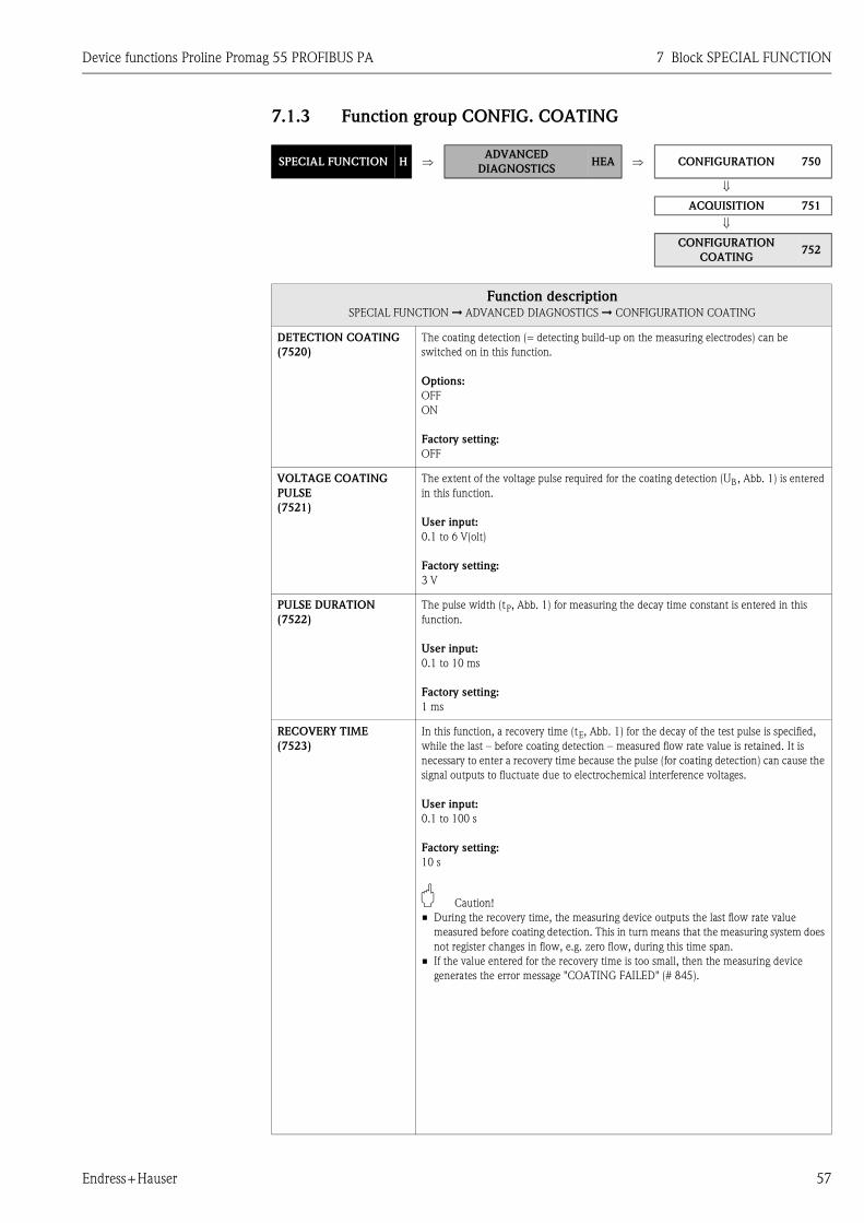
Device functions Proline Promag 55 PROFIBUS PA 7 Block SPECIAL FUNCTION
Endress+Hauser 57
7.1.3 Function group CONFIG. COATING
SPECIAL FUNCTION H ⇒ADVANCED
DIAGNOSTICSHEA ⇒ CONFIGURATION 750
⇓ ACQUISITION 751
⇓ CONFIGURATION
COATING752
Function descriptionSPECIAL FUNCTION ➞ ADVANCED DIAGNOSTICS ➞ CONFIGURATION COATING
DETECTION COATING
(7520)
The coating detection (= detecting build-up on the measuring electrodes) can be
switched on in this function.
Options:
OFF
ON
Factory setting:
OFF
VOLTAGE COATING
PULSE
(7521)
The extent of the voltage pulse required for the coating detection (UB, Abb. 1) is entered
in this function.
User input:
0.1 to 6 V(olt)
Factory setting:
3 V
PULSE DURATION
(7522)
The pulse width (tP, Abb. 1) for measuring the decay time constant is entered in this
function.
User input:
0.1 to 10 ms
Factory setting:
1 ms
RECOVERY TIME
(7523)
In this function, a recovery time (tE, Abb. 1) for the decay of the test pulse is specified,
while the last – before coating detection – measured flow rate value is retained. It is
necessary to enter a recovery time because the pulse (for coating detection) can cause the
signal outputs to fluctuate due to electrochemical interference voltages.
User input:
0.1 to 100 s
Factory setting:
10 s
" Caution!
• During the recovery time, the measuring device outputs the last flow rate value
measured before coating detection. This in turn means that the measuring system does
not register changes in flow, e.g. zero flow, during this time span.
• If the value entered for the recovery time is too small, then the measuring device
generates the error message "COATING FAILED" (# 845).

7 Block SPECIAL FUNCTION Device functions Proline Promag 55 PROFIBUS PA
58 Endress+Hauser
7.1.4 Function group COATING E1
SPECIAL FUNCTION H ⇒ADVANCED
DIAGNOSTICSHEA ⇒ CONFIGURATION 750
⇓ ACQUISITION 751
⇓ CONFIGURATION
COATING752
⇓ COATING E1 753
Function descriptionSPECIAL FUNCTION ➞ ADVANCED DIAGNOSTICS ➞ COATING E1
REFERENCE VALUE
(7530)
Use this function to view the reference value for the decay time constant at measuring
electrode 1.
User interface:
5-digit floating-point number, including unit in milliseconds
ACTUAL VALUE
(7531)
Use this function to view the actual measured decay time constant at measuring
electrode 1.
User interface:
5-digit floating-point number, including unit in milliseconds
MINIMUM VALUE
(7532)
Use this function to view the lowest measured value for the decay time constant at
measuring electrode 1, since the last reset or deletion of the stored values.
User interface:
5-digit floating-point number, including unit in milliseconds
MAXIMUM VALUE
(7533)
Use this function to view the highest measured value for the decay time constant at
measuring electrode 1, since the last reset or deletion of the stored values.
User interface:
5-digit floating-point number, including unit in milliseconds
HISTORY
(7534)
Use this function to view the last 10 measuring values for the decay time constant at
measuring electrode 1, since the last reset or deletion of the stored values.
User interface:
5-digit floating-point number, including unit in milliseconds
ACTUAL DEVIATION
(7535)
Use this function to view the deviation between the actual (last measured) value for the
decay time constant at measuring electrode 1 and the reference values selected in the
SELECTION REFERENCE STATUS function (7502).
User interface:
5-digit floating-point number, including unit in milliseconds
WARNING
(7536) ! Note!
This function is not available unless the ON setting was selected in the WARNING
MODE function (7503).
In this function, the user can specify a maximum permitted deviation (limit value) from
the reference status for the decay time constant. If this limit value is overshot or
undershot, a system error message (categorized as a notice message) is output. To do this,
the measuring system compares the actual deviation (see Function ACTUAL
DEVIATION, 7535) to the value entered here.
User input:
1 to 10000 ms
Factory setting:
100 ms

Device functions Proline Promag 55 PROFIBUS PA 7 Block SPECIAL FUNCTION
Endress+Hauser 59
7.1.5 Function group COATING E2
SPECIAL FUNCTION H ⇒ADVANCED
DIAGNOSTICSHEA ⇒ CONFIGURATION 750
⇓ ACQUISITION 751
⇓ CONFIGURATION
COATING752
⇓ COATING E1 753
⇓ COATING E2 754
Function descriptionSPECIAL FUNCTION ➞ ADVANCED DIAGNOSTICS ➞ COATING E2
REFERENCE VALUE
(7540)
Use this function to view the reference value for the decay time constant at measuring
electrode 2.
User interface:
5-digit floating-point number, including unit in milliseconds
ACTUAL VALUE
(7541)
Use this function to view the actual measured decay time constant at measuring
electrode 2.
User interface:
5-digit floating-point number, including unit in milliseconds
MINIMUM VALUE
(7542)
Use this function to view the lowest measured value for the decay time constant at
measuring electrode 2, since the last reset or deletion of the stored values.
User interface:
5-digit floating-point number, including unit in milliseconds
MAXIMUM VALUE
(7543)
Use this function to view the highest measured value for the decay time constant at
measuring electrode 2, since the last reset or deletion of the stored values.
User interface:
5-digit floating-point number, including unit in milliseconds
HISTORY
(7544)
Use this function to view the last 10 measured values for the decay time constant at
measuring electrode 2, since the last reset or deletion of the stored values.
User interface:
5-digit floating-point number, including unit in milliseconds
ACTUAL DEVIATION
(7545)
Use this function to view the deviation between the actual (last measured) value for the
decay time constant at measuring electrode 2 and the reference values selected in the
SELECTION REFERENCE STATUS function (7502).
User interface:
5-digit floating-point number, including unit in milliseconds
WARNING
(7546) ! Note!
This function is not available unless the ON setting was selected in the WARNING
MODE function (7503).
In this function, the user can enter a maximum permitted deviation (limit value) from the
reference status for the decay time constant. If this limit value is overshot or undershot, a
system error message (categorized as a notice message) is output. To do this, the
measuring system compares the actual deviation (see Function ACTUAL DEVIATION,
7535) to the value entered here.
User input:
1 to 10000 ms
Factory setting:
100 ms
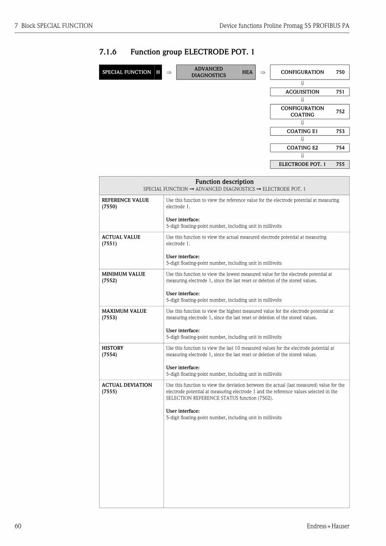
7 Block SPECIAL FUNCTION Device functions Proline Promag 55 PROFIBUS PA
60 Endress+Hauser
7.1.6 Function group ELECTRODE POT. 1
SPECIAL FUNCTION H ⇒ADVANCED
DIAGNOSTICSHEA ⇒ CONFIGURATION 750
⇓ ACQUISITION 751
⇓ CONFIGURATION
COATING752
⇓ COATING E1 753
⇓ COATING E2 754
⇓ ELECTRODE POT. 1 755
Function descriptionSPECIAL FUNCTION ➞ ADVANCED DIAGNOSTICS ➞ ELECTRODE POT. 1
REFERENCE VALUE
(7550)
Use this function to view the reference value for the electrode potential at measuring
electrode 1.
User interface:
5-digit floating-point number, including unit in millivolts
ACTUAL VALUE
(7551)
Use this function to view the actual measured electrode potential at measuring
electrode 1.
User interface:
5-digit floating-point number, including unit in millivolts
MINIMUM VALUE
(7552)
Use this function to view the lowest measured value for the electrode potential at
measuring electrode 1, since the last reset or deletion of the stored values.
User interface:
5-digit floating-point number, including unit in millivolts
MAXIMUM VALUE
(7553)
Use this function to view the highest measured value for the electrode potential at
measuring electrode 1, since the last reset or deletion of the stored values.
User interface:
5-digit floating-point number, including unit in millivolts
HISTORY
(7554)
Use this function to view the last 10 measured values for the electrode potential at
measuring electrode 1, since the last reset or deletion of the stored values.
User interface:
5-digit floating-point number, including unit in millivolts
ACTUAL DEVIATION
(7555)
Use this function to view the deviation between the actual (last measured) value for the
electrode potential at measuring electrode 1 and the reference values selected in the
SELECTION REFERENCE STATUS function (7502).
User interface:
5-digit floating-point number, including unit in millivolts

Device functions Proline Promag 55 PROFIBUS PA 7 Block SPECIAL FUNCTION
Endress+Hauser 61
7.1.7 Function group ELECTRODE POT. 2
SPECIAL FUNCTION H ⇒ADVANCED
DIAGNOSTICSHEA ⇒ CONFIGURATION 750
⇓ ACQUISITION 751
⇓ CONFIGURATION
COATING752
⇓ COATING E1 753
⇓ COATING E2 754
⇓ ELECTRODE POT. 1 755
⇓ ELECTRODE POT. 2 756
Function descriptionSPECIAL FUNCTION ➞ ADVANCED DIAGNOSTICS ➞ ELECTRODE POT. 2
REFERENCE VALUE
(7560)
Use this function to view the reference value for the electrode potential at measuring
electrode 2.
User interface:
5-digit floating-point number, including unit in millivolts
ACTUAL VALUE
(7561)
Use this function to view the actual measured electrode potential at measuring
electrode 2.
User interface:
5-digit floating-point number, including unit in millivolts
MINIMUM VALUE
(7562)
Use this function to view the lowest measured value for the electrode potential at
measuring electrode 2, since the last reset or deletion of the stored values.
User interface:
5-digit floating-point number, including unit in millivolts
MAXIMUM VALUE
(7563)
Use this function to view the highest measured value for the electrode potential at
measuring electrode 2, since the last reset or deletion of the stored values.
User interface:
5-digit floating-point number, including unit in millivolts
HISTORY
(7564)
Use this function to view the last 10 measured values for the electrode potential at
measuring electrode 2, since the last reset or deletion of the stored values.
User interface:
5-digit floating-point number, including unit in millivolts
ACTUAL DEVIATION
(7565)
Use this function to view the deviation between the actual (last measured) value for the
electrode potential at measuring electrode 2 and the reference values selected in the
SELECTION REFERENCE STATUS function (7502).
User interface:
5-digit floating-point number, including unit in millivolts
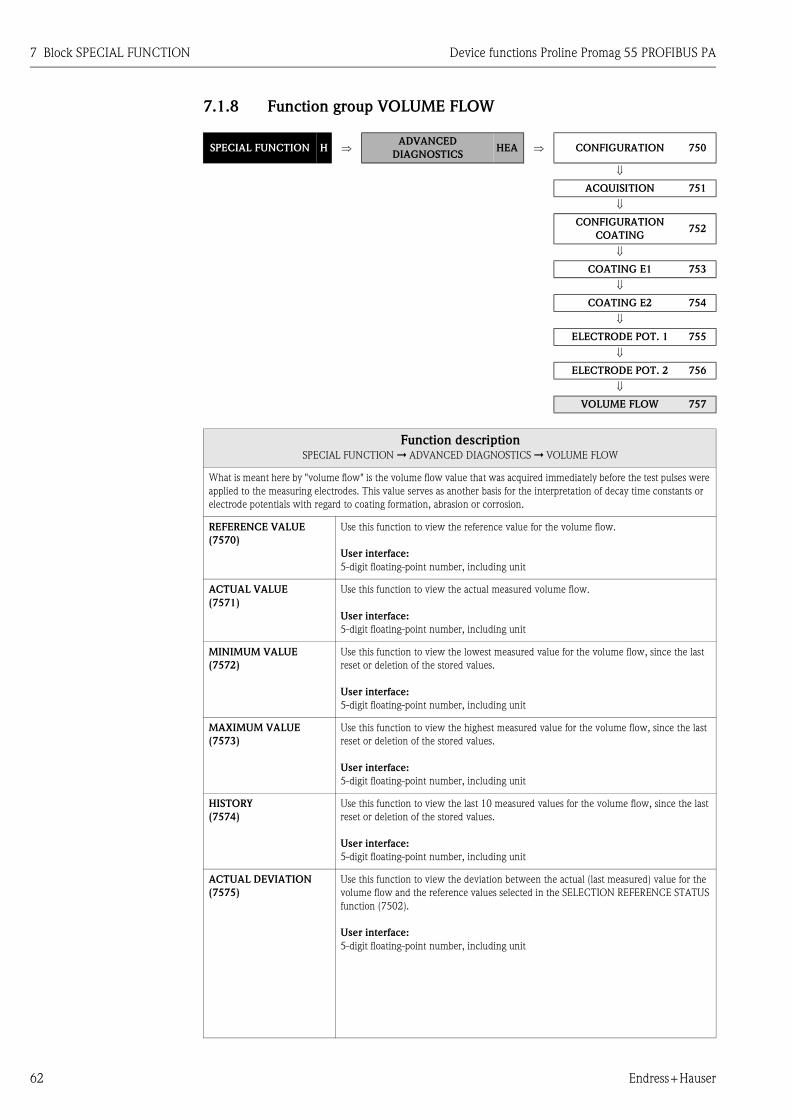
7 Block SPECIAL FUNCTION Device functions Proline Promag 55 PROFIBUS PA
62 Endress+Hauser
7.1.8 Function group VOLUME FLOW
SPECIAL FUNCTION H ⇒ADVANCED
DIAGNOSTICSHEA ⇒ CONFIGURATION 750
⇓ ACQUISITION 751
⇓ CONFIGURATION
COATING752
⇓ COATING E1 753
⇓ COATING E2 754
⇓ ELECTRODE POT. 1 755
⇓ ELECTRODE POT. 2 756
⇓ VOLUME FLOW 757
Function descriptionSPECIAL FUNCTION ➞ ADVANCED DIAGNOSTICS ➞ VOLUME FLOW
What is meant here by "volume flow" is the volume flow value that was acquired immediately before the test pulses were
applied to the measuring electrodes. This value serves as another basis for the interpretation of decay time constants or
electrode potentials with regard to coating formation, abrasion or corrosion.
REFERENCE VALUE
(7570)
Use this function to view the reference value for the volume flow.
User interface:
5-digit floating-point number, including unit
ACTUAL VALUE
(7571)
Use this function to view the actual measured volume flow.
User interface:
5-digit floating-point number, including unit
MINIMUM VALUE
(7572)
Use this function to view the lowest measured value for the volume flow, since the last
reset or deletion of the stored values.
User interface:
5-digit floating-point number, including unit
MAXIMUM VALUE
(7573)
Use this function to view the highest measured value for the volume flow, since the last
reset or deletion of the stored values.
User interface:
5-digit floating-point number, including unit
HISTORY
(7574)
Use this function to view the last 10 measured values for the volume flow, since the last
reset or deletion of the stored values.
User interface:
5-digit floating-point number, including unit
ACTUAL DEVIATION
(7575)
Use this function to view the deviation between the actual (last measured) value for the
volume flow and the reference values selected in the SELECTION REFERENCE STATUS
function (7502).
User interface:
5-digit floating-point number, including unit

Device functions Proline Promag 55 PROFIBUS PA 7 Block SPECIAL FUNCTION
Endress+Hauser 63
7.1.9 Function group NOISE VALUE
SPECIAL FUNCTION H ⇒ADVANCED DIAG-
NOSTICS
HEA⇒ CONFIGURATION
750
⇓ ACQUISITION 751
⇓ CONFIGURATION COA-
TING
752
⇓ COATING E1 753
⇓ COATING E2 754
⇓ ELECTRODE POT. 1 755
⇓ ELECTRODE POT. 2 756
⇓ VOLUME FLOW 757
⇓ NOISE VALUE 758
Function descriptionSPECIAL FUNCTION ➞ ADVANCED DIAGNOSTICS ➞ NOISE VALUE
NOISE VALUE ist the standard deviation of differential signal of both measuring electrodes. It is an additional indicator
for the quality of the measuring signal.
REFERENCE VALUE
(7580)
Use this function to view the reference value for the noise value.
User interface:
5-digit floating-point number, including unit in mV
ACTUAL VALUE
(7581)
Use this function to view the actual measured noise value.
User interface:
5-digit floating-point number, including unit in mV
MINIMUM VALUE
(7582)
Use this function to view the lowest measured value for the noise value, since the last
reset or deletion of the stored values.
User interface:
5-digit floating-point number, including unit in mV
MAXIMUM VALUE
(7583)
Use this function to view the highest measured value for the noise value, since the last
reset or deletion of the stored values.
User interface:
5-digit floating-point number, including unit in mV
HISTORY
(7584)
Use this function to view the last 10 measured values for the noise value, since the last
reset or deletion of the stored values.
User interface:
5-digit floating-point number, including unit in mV
ACTUAL DEVIATION
(7585)
Use this function to view the deviation between the actual (last measured) value for the
noise value and the reference values selected in the SELECTION REFERENCE STATUS
function (7502).
User interface:
5-digit floating-point number, including unit in mV
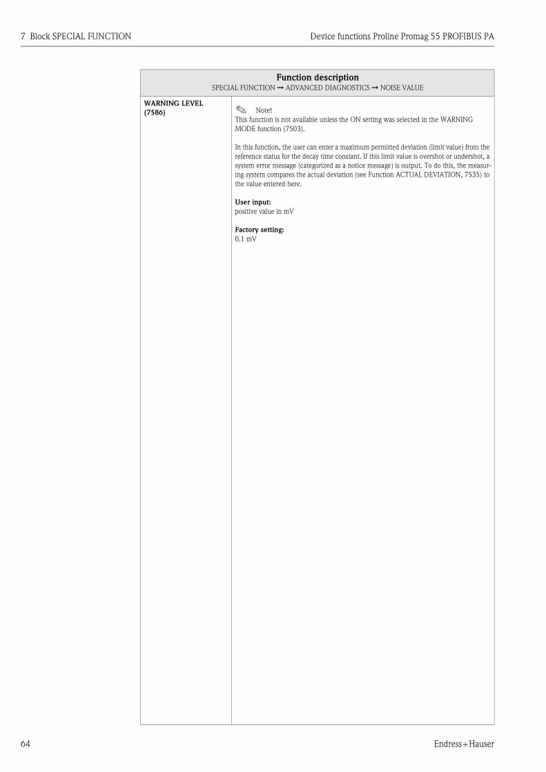
7 Block SPECIAL FUNCTION Device functions Proline Promag 55 PROFIBUS PA
64 Endress+Hauser
WARNING LEVEL
(7586) ! Note!
This function is not available unless the ON setting was selected in the WARNING
MODE function (7503).
In this function, the user can enter a maximum permitted deviation (limit value) from the
reference status for the decay time constant. If this limit value is overshot or undershot, a
system error message (categorized as a notice message) is output. To do this, the measur-
ing system compares the actual deviation (see Function ACTUAL DEVIATION, 7535) to
the value entered here.
User input:
positive value in mV
Factory setting:
0.1 mV
Function descriptionSPECIAL FUNCTION ➞ ADVANCED DIAGNOSTICS ➞ NOISE VALUE
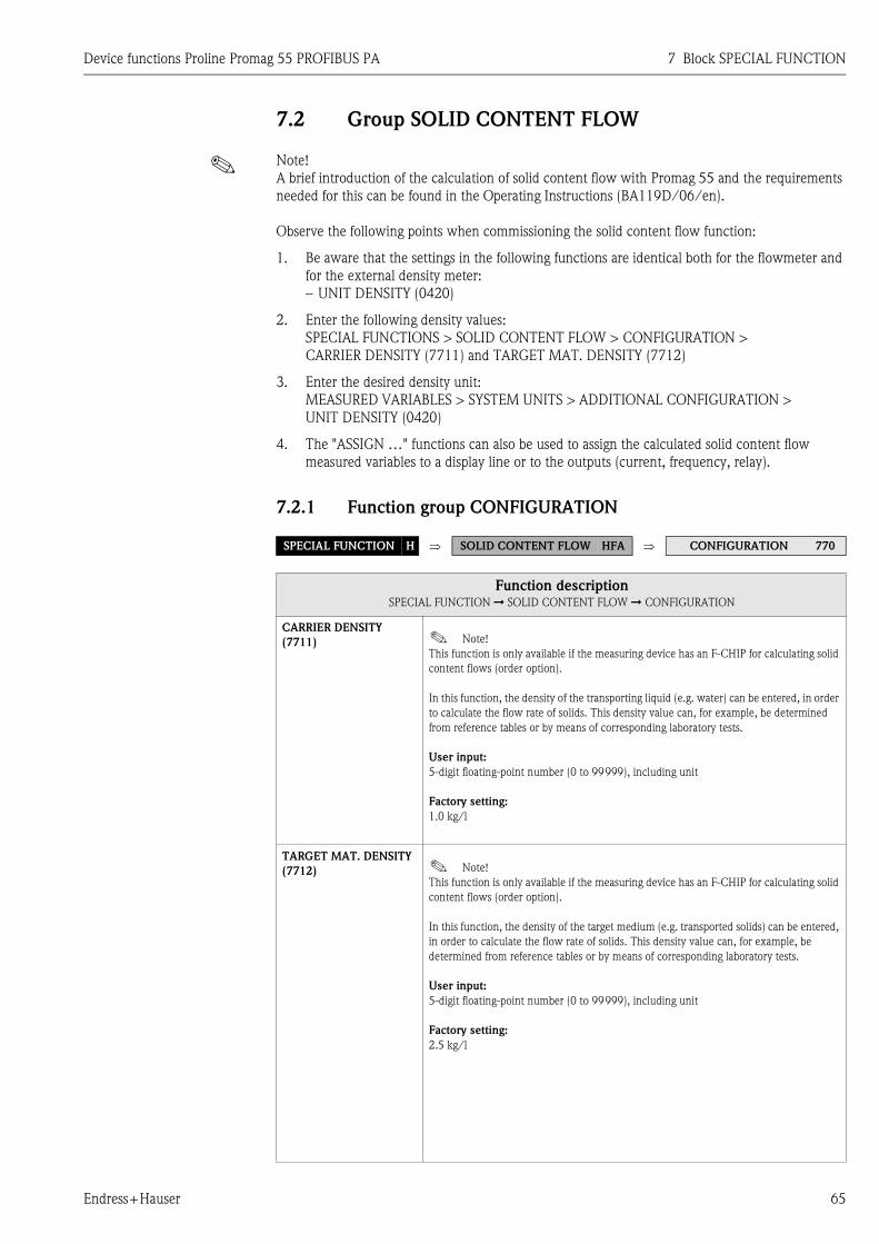
Device functions Proline Promag 55 PROFIBUS PA 7 Block SPECIAL FUNCTION
Endress+Hauser 65
7.2 Group SOLID CONTENT FLOW
! Note!
A brief introduction of the calculation of solid content flow with Promag 55 and the requirements
needed for this can be found in the Operating Instructions (BA119D/06/en).
Observe the following points when commissioning the solid content flow function:
1. Be aware that the settings in the following functions are identical both for the flowmeter and
for the external density meter:
– UNIT DENSITY (0420)
2. Enter the following density values:
SPECIAL FUNCTIONS > SOLID CONTENT FLOW > CONFIGURATION >
CARRIER DENSITY (7711) and TARGET MAT. DENSITY (7712)
3. Enter the desired density unit:
MEASURED VARIABLES > SYSTEM UNITS > ADDITIONAL CONFIGURATION >
UNIT DENSITY (0420)
4. The "ASSIGN …" functions can also be used to assign the calculated solid content flow
measured variables to a display line or to the outputs (current, frequency, relay).
7.2.1 Function group CONFIGURATION
SPECIAL FUNCTION H ⇒ SOLID CONTENT FLOW HFA ⇒ CONFIGURATION 770
Function descriptionSPECIAL FUNCTION ➞ SOLID CONTENT FLOW ➞ CONFIGURATION
CARRIER DENSITY
(7711) ! Note!
This function is only available if the measuring device has an F-CHIP for calculating solid
content flows (order option).
In this function, the density of the transporting liquid (e.g. water) can be entered, in order
to calculate the flow rate of solids. This density value can, for example, be determined
from reference tables or by means of corresponding laboratory tests.
User input:
5-digit floating-point number (0 to 99999), including unit
Factory setting:
1.0 kg/l
TARGET MAT. DENSITY
(7712) ! Note!
This function is only available if the measuring device has an F-CHIP for calculating solid
content flows (order option).
In this function, the density of the target medium (e.g. transported solids) can be entered,
in order to calculate the flow rate of solids. This density value can, for example, be
determined from reference tables or by means of corresponding laboratory tests.
User input:
5-digit floating-point number (0 to 99999), including unit
Factory setting:
2.5 kg/l

8 Block SUPERVISION Device functions Proline Promag 55 PROFIBUS PA
66 Endress+Hauser
8 Block SUPERVISION
Fu
ncti
on
s
OPE
RA
TIO
N
HO
UR
S
(80
48
) P
.6
9
SY
ST
EM
RE
SE
T
(80
46
) P
.6
9
VA
L. SIM
. M
EA
S.
(80
44
) P
.6
9
SIM
.
ME
ASU
RA
ND
(80
43
) P
.6
8
SIM
.
FA
ILSA
FE
MO
DE
(80
42
) P
.6
8
SO
FT
WA
RE
RE
VIS
ION
S-D
AT
(82
05
) P
.7
0
LA
NG
UA
GE
GR
OU
P
(82
26
) P
.7
1
ST
OR
AG
E
(80
07
) P
.6
7
PR
EV
. SY
S. C
ON
D.
(80
41
) P
.6
8
SE
NSO
R T
YPE
(82
01
) P
.7
0
SW
RE
V.
T-D
AT
(82
25
) P
.7
1
SW
RE
V.
I/O
MO
DU
LE
(83
03
) P
.7
2
⇒ ⇒ ⇒ ⇒ ⇒
ALA
RM
DE
LA
Y
(80
05
) P
.6
7
AC
T.
SY
ST
.
CO
ND
ITIO
N
(80
40
) P
.6
8
DE
VIC
E
SO
FT
WA
RE
(81
00
) P
.7
0
SE
RIA
L N
UM
BER
(82
00
) P
.7
0
SW
RE
V.
AM
PLIF
IER
(82
22
) P
.7
1
ST
AT
US F
-CH
IP
(82
40
) P
.7
1
I/O
MO
DU
LE
TY
PE
(83
00
) P
.7
2
⇒ ⇒ ⇒ ⇒ ⇒ ⇒ ⇒
Fu
nct
ion
gro
up
s
CO
NFIG
UR
AT
ION
(80
0)
P.67
⇓ ⇑
OP
ER
AT
ION
(80
4)
P.68
DE
VIC
E
(81
0)
P.70
⇓ ⇑
SE
NSO
R
(82
0)
P.70
⇓ ⇑
AM
PLIF
IER
(82
2)
P.
71
⇓ ⇑
F-C
HIP
(82
4)
P.71
⇓ ⇑
I/O
MO
DU
LE
(83
0)
P.72
⇒ ⇒
Gro
up
s
SY
ST
EM
(JA
A)
P.6
7
⇓ ⇑
⇓ ⇑
VE
RSIO
N I
NFO
(JC
A)
P.
70
⇒
Blo
ck
SU
PE
RV
ISIO
N
(J)
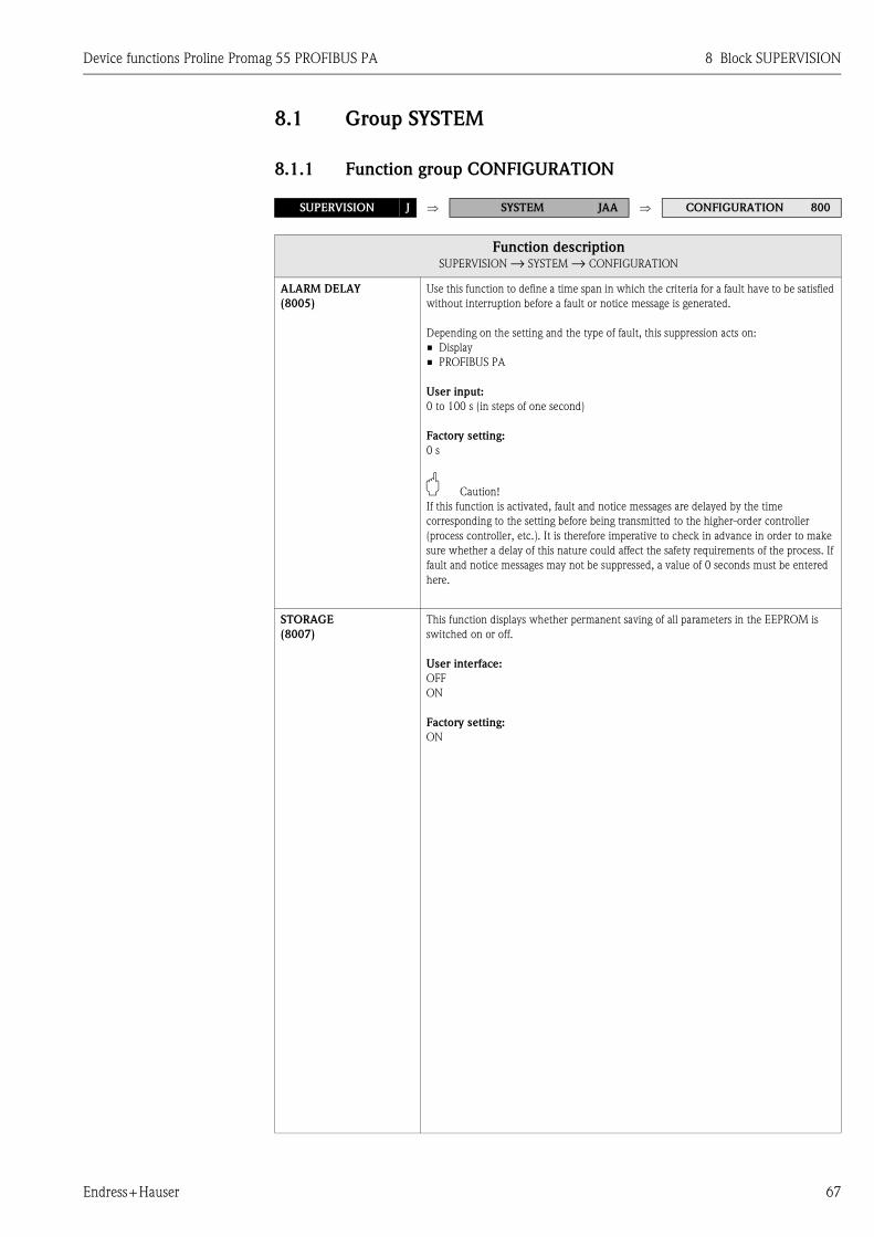
Device functions Proline Promag 55 PROFIBUS PA 8 Block SUPERVISION
Endress+Hauser 67
8.1 Group SYSTEM
8.1.1 Function group CONFIGURATION
SUPERVISION J ⇒ SYSTEM JAA ⇒ CONFIGURATION 800
Function descriptionSUPERVISION → SYSTEM → CONFIGURATION
ALARM DELAY
(8005)
Use this function to define a time span in which the criteria for a fault have to be satisfied
without interruption before a fault or notice message is generated.
Depending on the setting and the type of fault, this suppression acts on:
• Display
• PROFIBUS PA
User input:
0 to 100 s (in steps of one second)
Factory setting:
0 s
" Caution!
If this function is activated, fault and notice messages are delayed by the time
corresponding to the setting before being transmitted to the higher-order controller
(process controller, etc.). It is therefore imperative to check in advance in order to make
sure whether a delay of this nature could affect the safety requirements of the process. If
fault and notice messages may not be suppressed, a value of 0 seconds must be entered
here.
STORAGE
(8007)
This function displays whether permanent saving of all parameters in the EEPROM is
switched on or off.
User interface:
OFF
ON
Factory setting:
ON
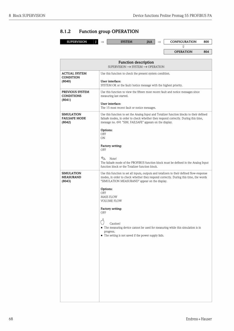
8 Block SUPERVISION Device functions Proline Promag 55 PROFIBUS PA
68 Endress+Hauser
8.1.2 Function group OPERATION
SUPERVISION J ⇒ SYSTEM JAA ⇒ CONFIGURATION 800
⇓
OPERATION 804
Function descriptionSUPERVISION → SYSTEM → OPERATION
ACTUAL SYSTEM
CONDITION
(8040)
Use this function to check the present system condition.
User interface:
SYSTEM OK or the fault/notice message with the highest priority.
PREVIOUS SYSTEM
CONDITIONS
(8041)
Use this function to view the fifteen most recent fault and notice messages since
measuring last started.
User interface:
The 15 most recent fault or notice messages.
SIMULATION
FAILSAFE MODE
(8042)
Use this function to set the Analog Input and Totalizer function blocks to their defined
failsafe modes, in order to check whether they respond correctly. During this time,
message no. 691 "SIM. FAILSAFE" appears on the display.
Options:
OFF
ON
Factory setting:
OFF
! Note!
The failsafe mode of the PROFIBUS function block must be defined in the Analog Input
function block or the Totalizer function block.
SIMULATION
MEASURAND
(8043)
Use this function to set all inputs, outputs and totalizers to their defined flow-response
modes, in order to check whether they respond correctly. During this time, the words
"SIMULATION MEASURAND" appear on the display.
Options:
OFF
MASS FLOW
VOLUME FLOW
Factory setting:
OFF
" Caution!
• The measuring device cannot be used for measuring while this simulation is in
progress.
• The setting is not saved if the power supply fails.
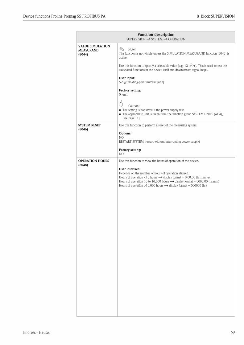
Device functions Proline Promag 55 PROFIBUS PA 8 Block SUPERVISION
Endress+Hauser 69
VALUE SIMULATION
MEASURAND
(8044)
! Note!
The function is not visible unless the SIMULATION MEASURAND function (8043) is
active.
Use this function to specify a selectable value (e.g. 12 m3/s). This is used to test the
associated functions in the device itself and downstream signal loops.
User input:
5-digit floating-point number [unit]
Factory setting:
0 [unit]
" Caution!
• The setting is not saved if the power supply fails.
• The appropriate unit is taken from the function group SYSTEM UNITS (ACA),
(see Page 11).
SYSTEM RESET
(8046)
Use this function to perform a reset of the measuring system.
Options:
NO
RESTART SYSTEM (restart without interrupting power supply)
Factory setting:
NO
OPERATION HOURS
(8048)
Use this function to view the hours of operation of the device.
User interface:
Depends on the number of hours of operation elapsed:
Hours of operation <10 hours → display format = 0:00:00 (hr:min:sec)
Hours of operation 10 to 10,000 hours → display format = 0000:00 (hr:min)
Hours of operation >10,000 hours → display format = 000000 (hr)
Function descriptionSUPERVISION → SYSTEM → OPERATION

8 Block SUPERVISION Device functions Proline Promag 55 PROFIBUS PA
70 Endress+Hauser
8.2 Group VERSION INFO
8.2.1 Function group DEVICE
8.2.2 Function group SENSOR
SUPERVISION J ⇒ SYSTEM JAA
⇓ VERSION INFO JCA ⇒ DEVICE 810
Function descriptionSUPERVISION → VERSION INFO → DEVICE
DEVICE SOFTWARE
(8100)
Use this function to view the current device software version.
SUPERVISION J ⇒ SYSTEM JAA
⇓ VERSION INFO JCA ⇒ DEVICE 810
⇓
SENSOR 820
Function descriptionSUPERVISION → VERSION INFO → SENSOR
SERIAL NUMBER
(8200)
Use this function to view the serial number of the sensor.
SENSOR TYPE
(8201)
Use this function to view the sensor type.
SOFTWARE
REVISION NUMBER
S-DAT
(8205)
Use this function to view the software revision number of the software used to create the
content of the S-DAT.

Device functions Proline Promag 55 PROFIBUS PA 8 Block SUPERVISION
Endress+Hauser 71
8.2.3 Function group AMPLIFIER
8.2.4 Function group F-CHIP
SUPERVISION J ⇒ SYSTEM JAA
⇓
VERSION INFO JCA ⇒ DEVICE 810
⇓
SENSOR 820
⇓
AMPLIFIER 822
Function descriptionSUPERVISION → VERSION INFO → AMPLIFIER
SOFTWARE REVISION
NUMBER AMPLIFIER
(8222)
Use this function to view the software revision number of the amplifier.
SOFTWARE
REVISION NUMBER
T-DAT
(8225)
Use this function to view the software revision number of the software used to
create the content of the T-DAT.
LANGUAGE GROUP
(8226)
Use this function to view the language group.
The following language groups can be ordered: WEST EU / USA, EAST EU / SCAND.,
ASIA, CHINA.
User interface:
available language group
! Note!
• The language options of the available language group are displayed in the LANGUAGE
(2000) function.
• You can change the language group via the configuration program FieldCare. Please do
not hesitate to contact your Endress+Hauser sales office if you have any questions.
SUPERVISION J ⇒ SYSTEM JAA
⇓
VERSION INFO JCA ⇒ DEVICE 810
⇓
SENSOR 820
⇓
AMPLIFIER 822
⇓
F-CHIP 824
Function descriptionSUPERVISION → VERSION INFO → F-CHIP
STATUS F-CHIP
(8240)
Use this function to check whether an F-CHIP is installed and which software options are
available.
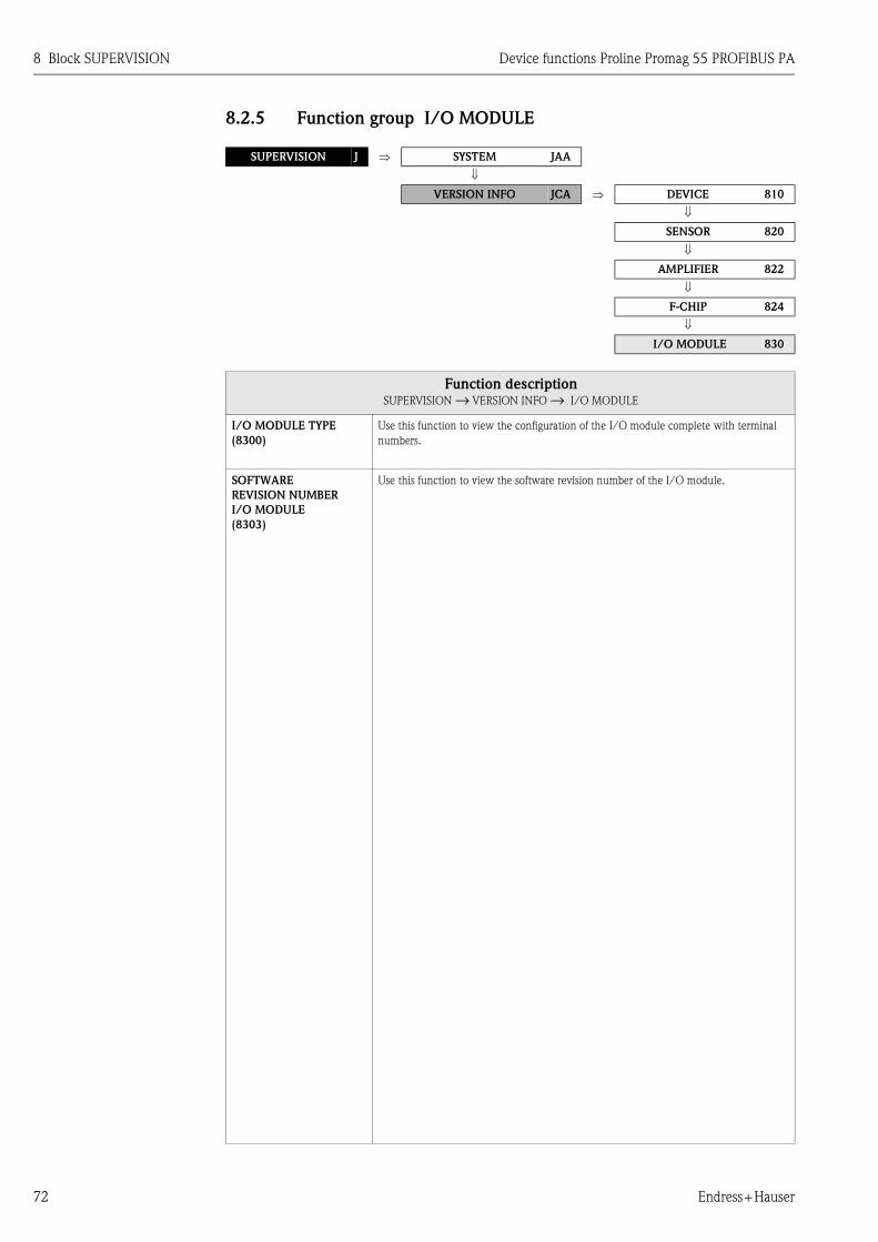
8 Block SUPERVISION Device functions Proline Promag 55 PROFIBUS PA
72 Endress+Hauser
8.2.5 Function group I/O MODULE
SUPERVISION J ⇒ SYSTEM JAA
⇓
VERSION INFO JCA ⇒ DEVICE 810
⇓
SENSOR 820
⇓
AMPLIFIER 822
⇓
F-CHIP 824
⇓
I/O MODULE 830
Function descriptionSUPERVISION → VERSION INFO → I/O MODULE
I/O MODULE TYPE
(8300)
Use this function to view the configuration of the I/O module complete with terminal
numbers.
SOFTWARE
REVISION NUMBER
I/O MODULE
(8303)
Use this function to view the software revision number of the I/O module.
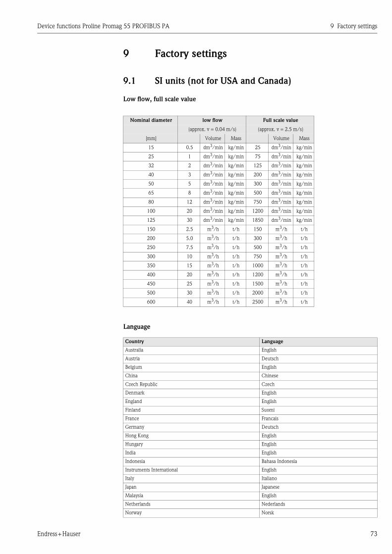
Device functions Proline Promag 55 PROFIBUS PA 9 Factory settings
Endress+Hauser 73
9 Factory settings
9.1 SI units (not for USA and Canada)
Low flow, full scale value
Language
Nominal diameter low flow Full scale value
(approx. v = 0.04 m/s) (approx. v = 2.5 m/s)
[mm] Volume Mass Volume Mass
15 0.5 dm3/min kg/min 25 dm3/min kg/min
25 1 dm3/min kg/min 75 dm3/min kg/min
32 2 dm3/min kg/min 125 dm3/min kg/min
40 3 dm3/min kg/min 200 dm3/min kg/min
50 5 dm3/min kg/min 300 dm3/min kg/min
65 8 dm3/min kg/min 500 dm3/min kg/min
80 12 dm3/min kg/min 750 dm3/min kg/min
100 20 dm3/min kg/min 1200 dm3/min kg/min
125 30 dm3/min kg/min 1850 dm3/min kg/min
150 2.5 m3/h t/h 150 m3/h t/h
200 5.0 m3/h t/h 300 m3/h t/h
250 7.5 m3/h t/h 500 m3/h t/h
300 10 m3/h t/h 750 m3/h t/h
350 15 m3/h t/h 1000 m3/h t/h
400 20 m3/h t/h 1200 m3/h t/h
450 25 m3/h t/h 1500 m3/h t/h
500 30 m3/h t/h 2000 m3/h t/h
600 40 m3/h t/h 2500 m3/h t/h
Country Language
Australia English
Austria Deutsch
Belgium English
China Chinese
Czech Republic Czech
Denmark English
England English
Finland Suomi
France Francais
Germany Deutsch
Hong Kong English
Hungary English
India English
Indonesia Bahasa Indonesia
Instruments International English
Italy Italiano
Japan Japanese
Malaysia English
Netherlands Nederlands
Norway Norsk
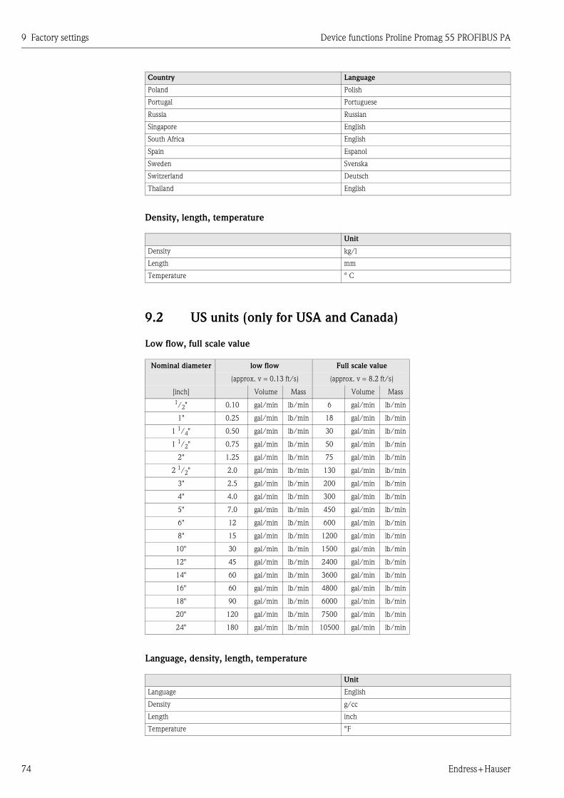
9 Factory settings Device functions Proline Promag 55 PROFIBUS PA
74 Endress+Hauser
Density, length, temperature
9.2 US units (only for USA and Canada)
Low flow, full scale value
Language, density, length, temperature
Poland Polish
Portugal Portuguese
Russia Russian
Singapore English
South Africa English
Spain Espanol
Sweden Svenska
Switzerland Deutsch
Thailand English
Unit
Density kg/l
Length mm
Temperature ° C
Nominal diameter low flow Full scale value
(approx. v = 0.13 ft/s) (approx. v = 8.2 ft/s)
[inch] Volume Mass Volume Mass
1/2" 0.10 gal/min lb/min 6 gal/min lb/min
1" 0.25 gal/min lb/min 18 gal/min lb/min
1 1/4" 0.50 gal/min lb/min 30 gal/min lb/min
1 1/2" 0.75 gal/min lb/min 50 gal/min lb/min
2" 1.25 gal/min lb/min 75 gal/min lb/min
2 1/2" 2.0 gal/min lb/min 130 gal/min lb/min
3" 2.5 gal/min lb/min 200 gal/min lb/min
4" 4.0 gal/min lb/min 300 gal/min lb/min
5" 7.0 gal/min lb/min 450 gal/min lb/min
6" 12 gal/min lb/min 600 gal/min lb/min
8" 15 gal/min lb/min 1200 gal/min lb/min
10" 30 gal/min lb/min 1500 gal/min lb/min
12" 45 gal/min lb/min 2400 gal/min lb/min
14" 60 gal/min lb/min 3600 gal/min lb/min
16" 60 gal/min lb/min 4800 gal/min lb/min
18" 90 gal/min lb/min 6000 gal/min lb/min
20" 120 gal/min lb/min 7500 gal/min lb/min
24" 180 gal/min lb/min 10500 gal/min lb/min
Unit
Language English
Density g/cc
Length inch
Temperature °F
Country Language
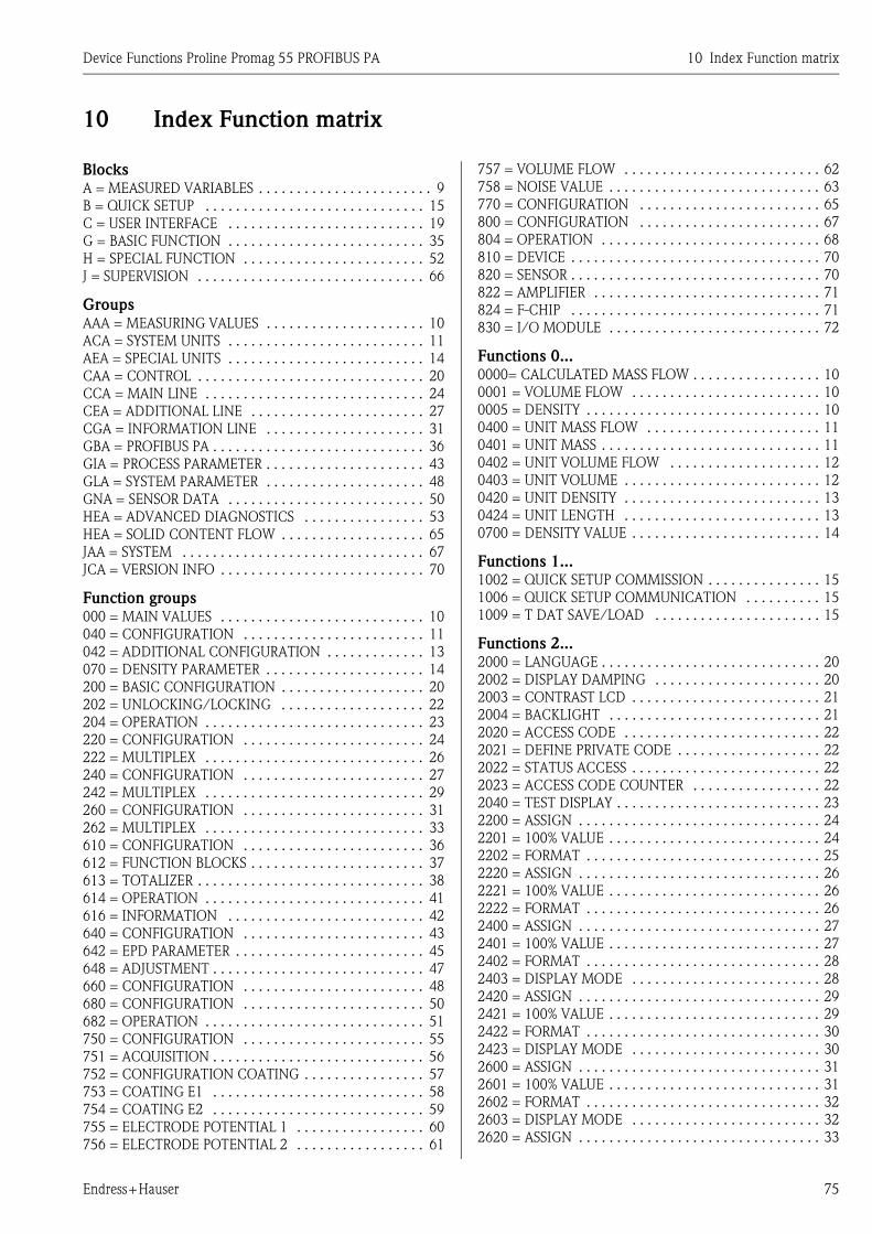
Device Functions Proline Promag 55 PROFIBUS PA 10 Index Function matrix
Endress+Hauser 75
10 Index Function matrix
BlocksA = MEASURED VARIABLES . . . . . . . . . . . . . . . . . . . . . . . 9
B = QUICK SETUP . . . . . . . . . . . . . . . . . . . . . . . . . . . . . 15
C = USER INTERFACE . . . . . . . . . . . . . . . . . . . . . . . . . . 19
G = BASIC FUNCTION . . . . . . . . . . . . . . . . . . . . . . . . . . 35
H = SPECIAL FUNCTION . . . . . . . . . . . . . . . . . . . . . . . . 52
J = SUPERVISION . . . . . . . . . . . . . . . . . . . . . . . . . . . . . . 66
GroupsAAA = MEASURING VALUES . . . . . . . . . . . . . . . . . . . . . 10
ACA = SYSTEM UNITS . . . . . . . . . . . . . . . . . . . . . . . . . . 11
AEA = SPECIAL UNITS . . . . . . . . . . . . . . . . . . . . . . . . . . 14
CAA = CONTROL . . . . . . . . . . . . . . . . . . . . . . . . . . . . . . 20
CCA = MAIN LINE . . . . . . . . . . . . . . . . . . . . . . . . . . . . . 24
CEA = ADDITIONAL LINE . . . . . . . . . . . . . . . . . . . . . . . 27
CGA = INFORMATION LINE . . . . . . . . . . . . . . . . . . . . . 31
GBA = PROFIBUS PA . . . . . . . . . . . . . . . . . . . . . . . . . . . . 36
GIA = PROCESS PARAMETER . . . . . . . . . . . . . . . . . . . . . 43
GLA = SYSTEM PARAMETER . . . . . . . . . . . . . . . . . . . . . 48
GNA = SENSOR DATA . . . . . . . . . . . . . . . . . . . . . . . . . . 50
HEA = ADVANCED DIAGNOSTICS . . . . . . . . . . . . . . . . 53
HEA = SOLID CONTENT FLOW . . . . . . . . . . . . . . . . . . . 65
JAA = SYSTEM . . . . . . . . . . . . . . . . . . . . . . . . . . . . . . . . 67
JCA = VERSION INFO . . . . . . . . . . . . . . . . . . . . . . . . . . . 70
Function groups000 = MAIN VALUES . . . . . . . . . . . . . . . . . . . . . . . . . . . 10
040 = CONFIGURATION . . . . . . . . . . . . . . . . . . . . . . . . 11
042 = ADDITIONAL CONFIGURATION . . . . . . . . . . . . . 13
070 = DENSITY PARAMETER . . . . . . . . . . . . . . . . . . . . . 14
200 = BASIC CONFIGURATION . . . . . . . . . . . . . . . . . . . 20
202 = UNLOCKING/LOCKING . . . . . . . . . . . . . . . . . . . 22
204 = OPERATION . . . . . . . . . . . . . . . . . . . . . . . . . . . . . 23
220 = CONFIGURATION . . . . . . . . . . . . . . . . . . . . . . . . 24
222 = MULTIPLEX . . . . . . . . . . . . . . . . . . . . . . . . . . . . . 26
240 = CONFIGURATION . . . . . . . . . . . . . . . . . . . . . . . . 27
242 = MULTIPLEX . . . . . . . . . . . . . . . . . . . . . . . . . . . . . 29
260 = CONFIGURATION . . . . . . . . . . . . . . . . . . . . . . . . 31
262 = MULTIPLEX . . . . . . . . . . . . . . . . . . . . . . . . . . . . . 33
610 = CONFIGURATION . . . . . . . . . . . . . . . . . . . . . . . . 36
612 = FUNCTION BLOCKS . . . . . . . . . . . . . . . . . . . . . . . 37
613 = TOTALIZER . . . . . . . . . . . . . . . . . . . . . . . . . . . . . . 38
614 = OPERATION . . . . . . . . . . . . . . . . . . . . . . . . . . . . . 41
616 = INFORMATION . . . . . . . . . . . . . . . . . . . . . . . . . . 42
640 = CONFIGURATION . . . . . . . . . . . . . . . . . . . . . . . . 43
642 = EPD PARAMETER . . . . . . . . . . . . . . . . . . . . . . . . . 45
648 = ADJUSTMENT . . . . . . . . . . . . . . . . . . . . . . . . . . . . 47
660 = CONFIGURATION . . . . . . . . . . . . . . . . . . . . . . . . 48
680 = CONFIGURATION . . . . . . . . . . . . . . . . . . . . . . . . 50
682 = OPERATION . . . . . . . . . . . . . . . . . . . . . . . . . . . . . 51
750 = CONFIGURATION . . . . . . . . . . . . . . . . . . . . . . . . 55
751 = ACQUISITION . . . . . . . . . . . . . . . . . . . . . . . . . . . . 56
752 = CONFIGURATION COATING . . . . . . . . . . . . . . . . 57
753 = COATING E1 . . . . . . . . . . . . . . . . . . . . . . . . . . . . 58
754 = COATING E2 . . . . . . . . . . . . . . . . . . . . . . . . . . . . 59
755 = ELECTRODE POTENTIAL 1 . . . . . . . . . . . . . . . . . 60
756 = ELECTRODE POTENTIAL 2 . . . . . . . . . . . . . . . . . 61
757 = VOLUME FLOW . . . . . . . . . . . . . . . . . . . . . . . . . . 62
758 = NOISE VALUE . . . . . . . . . . . . . . . . . . . . . . . . . . . . 63
770 = CONFIGURATION . . . . . . . . . . . . . . . . . . . . . . . . 65
800 = CONFIGURATION . . . . . . . . . . . . . . . . . . . . . . . . 67
804 = OPERATION . . . . . . . . . . . . . . . . . . . . . . . . . . . . . 68
810 = DEVICE . . . . . . . . . . . . . . . . . . . . . . . . . . . . . . . . . 70
820 = SENSOR . . . . . . . . . . . . . . . . . . . . . . . . . . . . . . . . . 70
822 = AMPLIFIER . . . . . . . . . . . . . . . . . . . . . . . . . . . . . . 71
824 = F-CHIP . . . . . . . . . . . . . . . . . . . . . . . . . . . . . . . . . 71
830 = I/O MODULE . . . . . . . . . . . . . . . . . . . . . . . . . . . . 72
Functions 0...0000= CALCULATED MASS FLOW . . . . . . . . . . . . . . . . . 10
0001 = VOLUME FLOW . . . . . . . . . . . . . . . . . . . . . . . . . 10
0005 = DENSITY . . . . . . . . . . . . . . . . . . . . . . . . . . . . . . . 10
0400 = UNIT MASS FLOW . . . . . . . . . . . . . . . . . . . . . . . 11
0401 = UNIT MASS . . . . . . . . . . . . . . . . . . . . . . . . . . . . . 11
0402 = UNIT VOLUME FLOW . . . . . . . . . . . . . . . . . . . . 12
0403 = UNIT VOLUME . . . . . . . . . . . . . . . . . . . . . . . . . . 12
0420 = UNIT DENSITY . . . . . . . . . . . . . . . . . . . . . . . . . . 13
0424 = UNIT LENGTH . . . . . . . . . . . . . . . . . . . . . . . . . . 13
0700 = DENSITY VALUE . . . . . . . . . . . . . . . . . . . . . . . . . 14
Functions 1...1002 = QUICK SETUP COMMISSION . . . . . . . . . . . . . . . 15
1006 = QUICK SETUP COMMUNICATION . . . . . . . . . . 15
1009 = T DAT SAVE/LOAD . . . . . . . . . . . . . . . . . . . . . . 15
Functions 2...2000 = LANGUAGE . . . . . . . . . . . . . . . . . . . . . . . . . . . . . 20
2002 = DISPLAY DAMPING . . . . . . . . . . . . . . . . . . . . . . 20
2003 = CONTRAST LCD . . . . . . . . . . . . . . . . . . . . . . . . . 21
2004 = BACKLIGHT . . . . . . . . . . . . . . . . . . . . . . . . . . . . 21
2020 = ACCESS CODE . . . . . . . . . . . . . . . . . . . . . . . . . . 22
2021 = DEFINE PRIVATE CODE . . . . . . . . . . . . . . . . . . . 22
2022 = STATUS ACCESS . . . . . . . . . . . . . . . . . . . . . . . . . 22
2023 = ACCESS CODE COUNTER . . . . . . . . . . . . . . . . . 22
2040 = TEST DISPLAY . . . . . . . . . . . . . . . . . . . . . . . . . . . 23
2200 = ASSIGN . . . . . . . . . . . . . . . . . . . . . . . . . . . . . . . . 24
2201 = 100% VALUE . . . . . . . . . . . . . . . . . . . . . . . . . . . . 24
2202 = FORMAT . . . . . . . . . . . . . . . . . . . . . . . . . . . . . . . 25
2220 = ASSIGN . . . . . . . . . . . . . . . . . . . . . . . . . . . . . . . . 26
2221 = 100% VALUE . . . . . . . . . . . . . . . . . . . . . . . . . . . . 26
2222 = FORMAT . . . . . . . . . . . . . . . . . . . . . . . . . . . . . . . 26
2400 = ASSIGN . . . . . . . . . . . . . . . . . . . . . . . . . . . . . . . . 27
2401 = 100% VALUE . . . . . . . . . . . . . . . . . . . . . . . . . . . . 27
2402 = FORMAT . . . . . . . . . . . . . . . . . . . . . . . . . . . . . . . 28
2403 = DISPLAY MODE . . . . . . . . . . . . . . . . . . . . . . . . . 28
2420 = ASSIGN . . . . . . . . . . . . . . . . . . . . . . . . . . . . . . . . 29
2421 = 100% VALUE . . . . . . . . . . . . . . . . . . . . . . . . . . . . 29
2422 = FORMAT . . . . . . . . . . . . . . . . . . . . . . . . . . . . . . . 30
2423 = DISPLAY MODE . . . . . . . . . . . . . . . . . . . . . . . . . 30
2600 = ASSIGN . . . . . . . . . . . . . . . . . . . . . . . . . . . . . . . . 31
2601 = 100% VALUE . . . . . . . . . . . . . . . . . . . . . . . . . . . . 31
2602 = FORMAT . . . . . . . . . . . . . . . . . . . . . . . . . . . . . . . 32
2603 = DISPLAY MODE . . . . . . . . . . . . . . . . . . . . . . . . . 32
2620 = ASSIGN . . . . . . . . . . . . . . . . . . . . . . . . . . . . . . . . 33

Device Functions Proline Promag 55 PROFIBUS PA 10 Index Function matrix
Endress+Hauser 76
2621 = 100% VALUE . . . . . . . . . . . . . . . . . . . . . . . . . . . . 34
2622 = FORMAT . . . . . . . . . . . . . . . . . . . . . . . . . . . . . . . 34
2623 = DISPLAY MODE . . . . . . . . . . . . . . . . . . . . . . . . . 34
Functions 6...6100 = TAG NAME . . . . . . . . . . . . . . . . . . . . . . . . . . . . . 36
6101 = FIELDBUS ADDRESS . . . . . . . . . . . . . . . . . . . . . . 36
6102 = WRITE PROTECT . . . . . . . . . . . . . . . . . . . . . . . . 36
6120 = BLOCK SELECTION . . . . . . . . . . . . . . . . . . . . . . 37
6121 = OUT VALUE . . . . . . . . . . . . . . . . . . . . . . . . . . . . 37
6122 = DISPLAY VALUE . . . . . . . . . . . . . . . . . . . . . . . . . 37
6130 = SELECT TOTALIZER . . . . . . . . . . . . . . . . . . . . . . 38
6131 = TOTALIZER OUT VALUE . . . . . . . . . . . . . . . . . . 38
6132 = OVERFLOW . . . . . . . . . . . . . . . . . . . . . . . . . . . . 38
6133 = CHANNEL . . . . . . . . . . . . . . . . . . . . . . . . . . . . . 38
6134 = UNIT TOTALIZER . . . . . . . . . . . . . . . . . . . . . . . . 39
6135 = SET TOTALIZER . . . . . . . . . . . . . . . . . . . . . . . . . 39
6136 = PRESET TOTALIZER . . . . . . . . . . . . . . . . . . . . . . 39
6137 = TOTALIZER MODE . . . . . . . . . . . . . . . . . . . . . . . 40
6138 = CYCL. CALC. TOT. . . . . . . . . . . . . . . . . . . . . . . . 40
6140 = SELECTION GSD . . . . . . . . . . . . . . . . . . . . . . . . 41
6141 = SET UNIT TO BUS . . . . . . . . . . . . . . . . . . . . . . . . 41
6160 = PROFILE VERSION . . . . . . . . . . . . . . . . . . . . . . . 42
6161 = ACTUAL BAUD RATE . . . . . . . . . . . . . . . . . . . . . 42
6162 = DEVICE ID . . . . . . . . . . . . . . . . . . . . . . . . . . . . . 42
6163 = CHECK CONFIGURATION . . . . . . . . . . . . . . . . . 42
6400 = ASSIGN LOW FLOW CUTOFF . . . . . . . . . . . . . . 43
6402 = ON-VALUE LOW FLOW CUTOFF . . . . . . . . . . . . 43
6403 = OFF-VALUE LOW FLOW CUTOFF . . . . . . . . . . . 43
6404 = PRESSURE SHOCK SUPPRESSION . . . . . . . . . . . 44
6420 = EMPTY PIPE DETECTION (EPD) . . . . . . . . . . . . 45
6425 = EPD RESPONSE TIME . . . . . . . . . . . . . . . . . . . . . 46
6481 = EPD ADJUSTMENT . . . . . . . . . . . . . . . . . . . . . . . 47
6600 = INSTALLATION DIRECTION SENSOR . . . . . . . . 48
6601 = MEASURING MODE . . . . . . . . . . . . . . . . . . . . . . 48
6603 = SYSTEM DAMPING . . . . . . . . . . . . . . . . . . . . . . 48
6604 = INTEGRATION TIME . . . . . . . . . . . . . . . . . . . . . 49
6605 = POSITIVE ZERO RETURN . . . . . . . . . . . . . . . . . . 49
6801 = K-FACTOR POSITIVE . . . . . . . . . . . . . . . . . . . . . 50
6802 = K-FACTOR NEGATIVE . . . . . . . . . . . . . . . . . . . . 50
6803 = ZERO POINT . . . . . . . . . . . . . . . . . . . . . . . . . . . . 50
6804 = NOMINAL DIAMETER . . . . . . . . . . . . . . . . . . . . 50
6820 = MEASURING PERIOD . . . . . . . . . . . . . . . . . . . . . 51
6822 = EPD ELECTRODE . . . . . . . . . . . . . . . . . . . . . . . . 51
Functions 7...7501 = REFERENCE STATUS USER . . . . . . . . . . . . . . . . 55
7502 = SELECTION REFERENCE STATUS . . . . . . . . . . . 55
7503 = WARNING MODE . . . . . . . . . . . . . . . . . . . . . . . 55
7510 = ACQUISITION MODE . . . . . . . . . . . . . . . . . . . . . 56
7511 = ACQUISITION PERIOD . . . . . . . . . . . . . . . . . . . . 56
7512 = ACQUISITION MANUAL . . . . . . . . . . . . . . . . . . 56
7513 = RESET HISTORY . . . . . . . . . . . . . . . . . . . . . . . . . 56
7520 = DETECTION COATING . . . . . . . . . . . . . . . . . . . 57
7521 = VOLTAGE COATING PULSE . . . . . . . . . . . . . . . . 57
7522 = PULSE DURATION . . . . . . . . . . . . . . . . . . . . . . . 57
7523 = RECOVERY TIME . . . . . . . . . . . . . . . . . . . . . . . . 57
7530 = REFERENCE VALUE COATING E1 . . . . . . . . . . . 58
7531 = ACTUAL VALUE COATING E1 . . . . . . . . . . . . . . 58
7532 = MINIMUM VALUE COATING E1 . . . . . . . . . . . . 58
7533 = MAXIMUM VALUE COATING E1 . . . . . . . . . . . . 58
7534 = MAXIMUM VALUE COATING E1 . . . . . . . . . . . . 58
7535 = ACT. DEVIATION COATING E1 . . . . . . . . . . . . . 58
7536 = WARNING COATING E1 . . . . . . . . . . . . . . . . . . 58
7540 = REFERENCE VALUE COATING E2 . . . . . . . . . . . 59
7541 = ACTUAL VALUE COATING E2 . . . . . . . . . . . . . . 59
7542 = MINIMUM VALUE COATING E2 . . . . . . . . . . . . 59
7543 = MAXIMUM VALUE COATING E2 . . . . . . . . . . . . 59
7544 = HISTORY COATING E2 . . . . . . . . . . . . . . . . . . . . 59
7545 = ACT. DEVIATION COATING E2 . . . . . . . . . . . . . 59
7546 = WARNING COATING E2 . . . . . . . . . . . . . . . . . . 59
7550 = REFERENCE VALUE ELECTR. POT. 1 . . . . . . . . . 60
7551 = ACTUAL VALUE ELECTR. POT. 1 . . . . . . . . . . . . 60
7552 = MINIMUM VALUE ELECTR. POT. 1 . . . . . . . . . . 60
7553 = MAXIMUM VALUE ELECTR. POT. 1 . . . . . . . . . . 60
7554 = HISTORY ELECTR. POT. 1 . . . . . . . . . . . . . . . . . 60
7555 = ACT. DEVIATION ELECTR. POT. 1 . . . . . . . . . . . 60
7560 = REFERENCE VALUE ELECTR. POT. 2 . . . . . . . . . 61
7561 = ACTUAL VALUE ELECTR. POT. 2 . . . . . . . . . . . . 61
7562 = MINIMUM VALUE ELECTR. POT. 2 . . . . . . . . . . 61
7563 = MAXIMUM VALUE ELECTR. POT. 2 . . . . . . . . . . 61
7564 = HISTORY ELECTR. POT. 2 . . . . . . . . . . . . . . . . . 61
7565 = ACT. DEVIATION ELECTR. POT. 2 . . . . . . . . . . . 61
7570 = REFERENCE VALUE VOLUME FLOW . . . . . . . . . 62
7571 = ACTUAL VALUE VOLUME FLOW . . . . . . . . . . . . 62
7572 = MINIMUM VALUE VOLUME FLOW . . . . . . . . . . 62
7573 = MAXIMUM VALUE VOLUME FLOW . . . . . . . . . 62
7574 = HISTORY VOLUME FLOW . . . . . . . . . . . . . . . . . 62
7575 = ACT. DEVIATION VOLUME FLOW . . . . . . . . . . . 62
7580 = REFERENCE VALUE . . . . . . . . . . . . . . . . . . . . . . 63
7581 = ACTUAL VALUE NOISE VALUE . . . . . . . . . . . . . 63
7582 = MINIMUM VALUE NOISE VALUE . . . . . . . . . . . 63
7583 = MAXIMUM VALUE NOISE VALUE . . . . . . . . . . . 63
7584 = HISTORY NOISE VALUE . . . . . . . . . . . . . . . . . . . 63
7585 = ACTUAL DEVIATION NOISE VALUE . . . . . . . . . 63
7586 = WARNING NOISE VALUE . . . . . . . . . . . . . . . . . . 64
7711 = CARRIER DENSITY . . . . . . . . . . . . . . . . . . . . . . . 65
7712 = TARGET MAT. DENSITY . . . . . . . . . . . . . . . . . . . 65
Functions 8...8005 = ALARM DELAY . . . . . . . . . . . . . . . . . . . . . . . . . . 67
8007 = PERMANENT SAVING . . . . . . . . . . . . . . . . . . . . 67
8040 = ACTUAL SYSTEM CONDITION . . . . . . . . . . . . . 68
8041 = PREVIOUS SYSTEM CONDITIONS . . . . . . . . . . . 68
8042 = SIMULATION FAILSAFE MODE . . . . . . . . . . . . . 68
8043 = SIMULATION MEASURAND . . . . . . . . . . . . . . . . 68
8044 = VALUE SIMULATION MEASURAND . . . . . . . . . . 69
8046 = SYSTEM RESET . . . . . . . . . . . . . . . . . . . . . . . . . . 69
8048 = OPERATION HOURS . . . . . . . . . . . . . . . . . . . . . . 69
8100 = DEVICE SOFTWARE . . . . . . . . . . . . . . . . . . . . . . 70
8200 = SERIAL NUMBER . . . . . . . . . . . . . . . . . . . . . . . . 70
8201 = SENSOR TYPE . . . . . . . . . . . . . . . . . . . . . . . . . . . 70
8205 = SOFTWARE REV. NO. S-DAT . . . . . . . . . . . . . . . 70
8222 = SOFTWARE REV. NO. AMPLIFIER . . . . . . . . . . . 71
8225 = SOFTWARE REV. NO. T-DAT . . . . . . . . . . . . . . . 71
8226 = LANGUAGE GROUP . . . . . . . . . . . . . . . . . . . . . . 71
8240 = STATUS F-CHIP . . . . . . . . . . . . . . . . . . . . . . . . . . 71
8300 = I/O MODULE TYPE . . . . . . . . . . . . . . . . . . . . . . 72
8303 = SOFTWARE REV. NO. I/O MODULE . . . . . . . . . 72
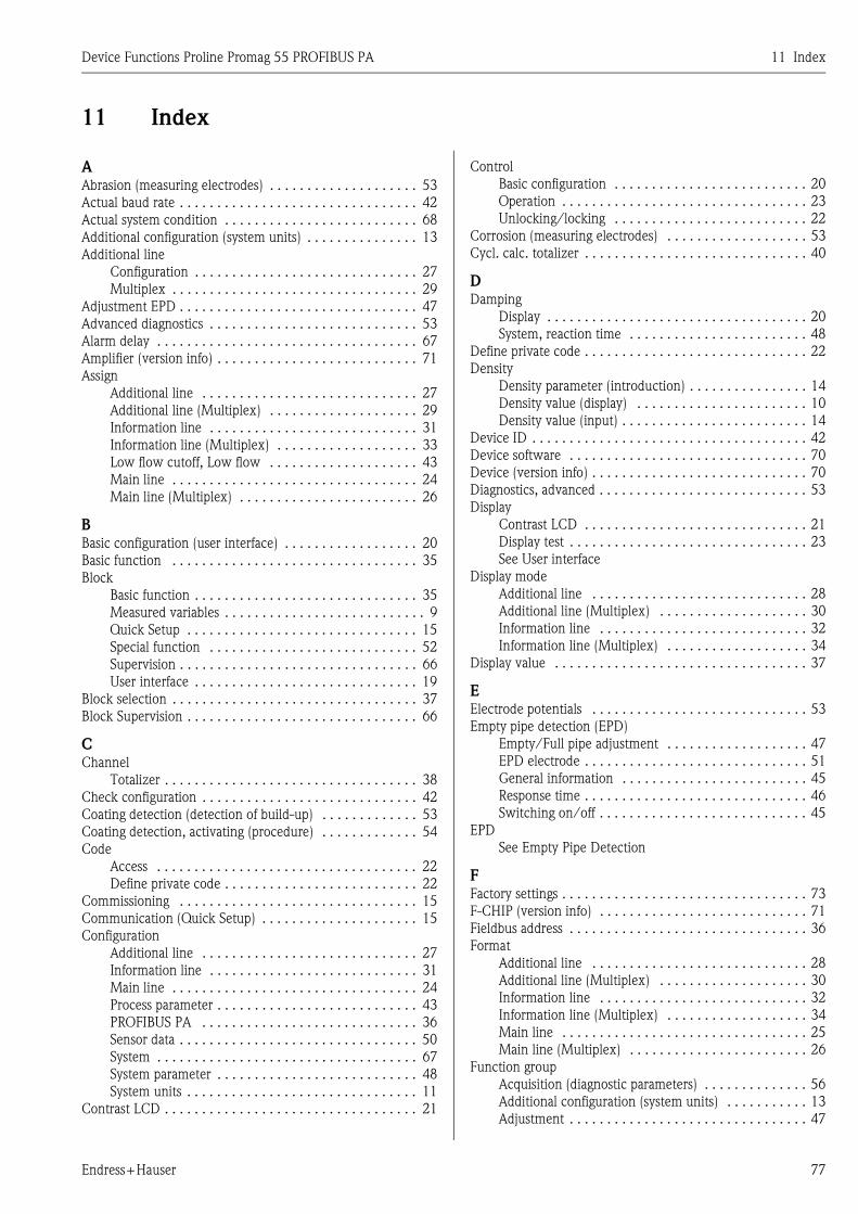
Device Functions Proline Promag 55 PROFIBUS PA 11 Index
Endress+Hauser 77
11 Index
AAbrasion (measuring electrodes) . . . . . . . . . . . . . . . . . . . . 53
Actual baud rate . . . . . . . . . . . . . . . . . . . . . . . . . . . . . . . . 42
Actual system condition . . . . . . . . . . . . . . . . . . . . . . . . . . 68
Additional configuration (system units) . . . . . . . . . . . . . . . 13
Additional line
Configuration . . . . . . . . . . . . . . . . . . . . . . . . . . . . . . 27
Multiplex . . . . . . . . . . . . . . . . . . . . . . . . . . . . . . . . . 29
Adjustment EPD . . . . . . . . . . . . . . . . . . . . . . . . . . . . . . . . 47
Advanced diagnostics . . . . . . . . . . . . . . . . . . . . . . . . . . . . 53
Alarm delay . . . . . . . . . . . . . . . . . . . . . . . . . . . . . . . . . . . 67
Amplifier (version info) . . . . . . . . . . . . . . . . . . . . . . . . . . . 71
Assign
Additional line . . . . . . . . . . . . . . . . . . . . . . . . . . . . . 27
Additional line (Multiplex) . . . . . . . . . . . . . . . . . . . . 29
Information line . . . . . . . . . . . . . . . . . . . . . . . . . . . . 31
Information line (Multiplex) . . . . . . . . . . . . . . . . . . . 33
Low flow cutoff, Low flow . . . . . . . . . . . . . . . . . . . . 43
Main line . . . . . . . . . . . . . . . . . . . . . . . . . . . . . . . . . 24
Main line (Multiplex) . . . . . . . . . . . . . . . . . . . . . . . . 26
BBasic configuration (user interface) . . . . . . . . . . . . . . . . . . 20
Basic function . . . . . . . . . . . . . . . . . . . . . . . . . . . . . . . . . 35
Block
Basic function . . . . . . . . . . . . . . . . . . . . . . . . . . . . . . 35
Measured variables . . . . . . . . . . . . . . . . . . . . . . . . . . . 9
Quick Setup . . . . . . . . . . . . . . . . . . . . . . . . . . . . . . . 15
Special function . . . . . . . . . . . . . . . . . . . . . . . . . . . . 52
Supervision . . . . . . . . . . . . . . . . . . . . . . . . . . . . . . . . 66
User interface . . . . . . . . . . . . . . . . . . . . . . . . . . . . . . 19
Block selection . . . . . . . . . . . . . . . . . . . . . . . . . . . . . . . . . 37
Block Supervision . . . . . . . . . . . . . . . . . . . . . . . . . . . . . . . 66
CChannel
Totalizer . . . . . . . . . . . . . . . . . . . . . . . . . . . . . . . . . . 38
Check configuration . . . . . . . . . . . . . . . . . . . . . . . . . . . . . 42
Coating detection (detection of build-up) . . . . . . . . . . . . . 53
Coating detection, activating (procedure) . . . . . . . . . . . . . 54
Code
Access . . . . . . . . . . . . . . . . . . . . . . . . . . . . . . . . . . . 22
Define private code . . . . . . . . . . . . . . . . . . . . . . . . . . 22
Commissioning . . . . . . . . . . . . . . . . . . . . . . . . . . . . . . . . 15
Communication (Quick Setup) . . . . . . . . . . . . . . . . . . . . . 15
Configuration
Additional line . . . . . . . . . . . . . . . . . . . . . . . . . . . . . 27
Information line . . . . . . . . . . . . . . . . . . . . . . . . . . . . 31
Main line . . . . . . . . . . . . . . . . . . . . . . . . . . . . . . . . . 24
Process parameter . . . . . . . . . . . . . . . . . . . . . . . . . . . 43
PROFIBUS PA . . . . . . . . . . . . . . . . . . . . . . . . . . . . . 36
Sensor data . . . . . . . . . . . . . . . . . . . . . . . . . . . . . . . . 50
System . . . . . . . . . . . . . . . . . . . . . . . . . . . . . . . . . . . 67
System parameter . . . . . . . . . . . . . . . . . . . . . . . . . . . 48
System units . . . . . . . . . . . . . . . . . . . . . . . . . . . . . . . 11
Contrast LCD . . . . . . . . . . . . . . . . . . . . . . . . . . . . . . . . . . 21
Control
Basic configuration . . . . . . . . . . . . . . . . . . . . . . . . . . 20
Operation . . . . . . . . . . . . . . . . . . . . . . . . . . . . . . . . . 23
Unlocking/locking . . . . . . . . . . . . . . . . . . . . . . . . . . 22
Corrosion (measuring electrodes) . . . . . . . . . . . . . . . . . . . 53
Cycl. calc. totalizer . . . . . . . . . . . . . . . . . . . . . . . . . . . . . . 40
DDamping
Display . . . . . . . . . . . . . . . . . . . . . . . . . . . . . . . . . . . 20
System, reaction time . . . . . . . . . . . . . . . . . . . . . . . . 48
Define private code . . . . . . . . . . . . . . . . . . . . . . . . . . . . . . 22
Density
Density parameter (introduction) . . . . . . . . . . . . . . . . 14
Density value (display) . . . . . . . . . . . . . . . . . . . . . . . 10
Density value (input) . . . . . . . . . . . . . . . . . . . . . . . . . 14
Device ID . . . . . . . . . . . . . . . . . . . . . . . . . . . . . . . . . . . . . 42
Device software . . . . . . . . . . . . . . . . . . . . . . . . . . . . . . . . 70
Device (version info) . . . . . . . . . . . . . . . . . . . . . . . . . . . . . 70
Diagnostics, advanced . . . . . . . . . . . . . . . . . . . . . . . . . . . . 53
Display
Contrast LCD . . . . . . . . . . . . . . . . . . . . . . . . . . . . . . 21
Display test . . . . . . . . . . . . . . . . . . . . . . . . . . . . . . . . 23
See User interface
Display mode
Additional line . . . . . . . . . . . . . . . . . . . . . . . . . . . . . 28
Additional line (Multiplex) . . . . . . . . . . . . . . . . . . . . 30
Information line . . . . . . . . . . . . . . . . . . . . . . . . . . . . 32
Information line (Multiplex) . . . . . . . . . . . . . . . . . . . 34
Display value . . . . . . . . . . . . . . . . . . . . . . . . . . . . . . . . . . 37
EElectrode potentials . . . . . . . . . . . . . . . . . . . . . . . . . . . . . 53
Empty pipe detection (EPD)
Empty/Full pipe adjustment . . . . . . . . . . . . . . . . . . . 47
EPD electrode . . . . . . . . . . . . . . . . . . . . . . . . . . . . . . 51
General information . . . . . . . . . . . . . . . . . . . . . . . . . 45
Response time . . . . . . . . . . . . . . . . . . . . . . . . . . . . . . 46
Switching on/off . . . . . . . . . . . . . . . . . . . . . . . . . . . . 45
EPD
See Empty Pipe Detection
FFactory settings . . . . . . . . . . . . . . . . . . . . . . . . . . . . . . . . . 73
F-CHIP (version info) . . . . . . . . . . . . . . . . . . . . . . . . . . . . 71
Fieldbus address . . . . . . . . . . . . . . . . . . . . . . . . . . . . . . . . 36
Format
Additional line . . . . . . . . . . . . . . . . . . . . . . . . . . . . . 28
Additional line (Multiplex) . . . . . . . . . . . . . . . . . . . . 30
Information line . . . . . . . . . . . . . . . . . . . . . . . . . . . . 32
Information line (Multiplex) . . . . . . . . . . . . . . . . . . . 34
Main line . . . . . . . . . . . . . . . . . . . . . . . . . . . . . . . . . 25
Main line (Multiplex) . . . . . . . . . . . . . . . . . . . . . . . . 26
Function group
Acquisition (diagnostic parameters) . . . . . . . . . . . . . . 56
Additional configuration (system units) . . . . . . . . . . . 13
Adjustment . . . . . . . . . . . . . . . . . . . . . . . . . . . . . . . . 47
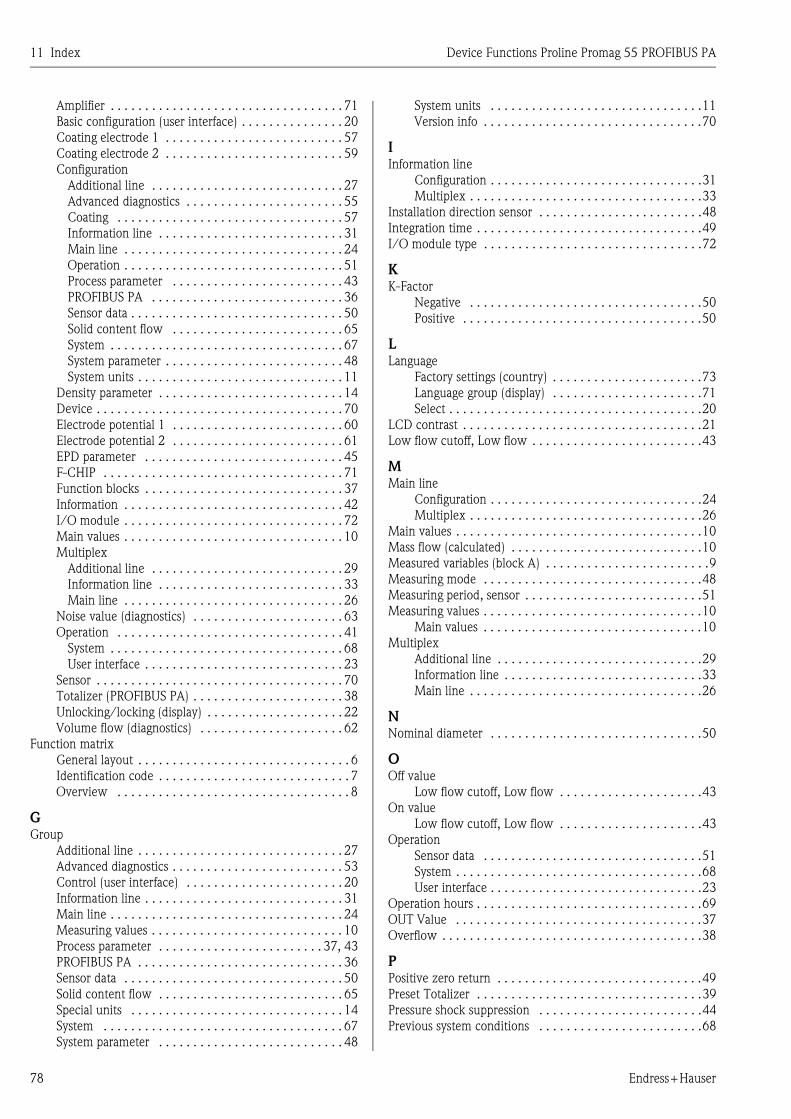
11 Index Device Functions Proline Promag 55 PROFIBUS PA
78 Endress+Hauser
Amplifier . . . . . . . . . . . . . . . . . . . . . . . . . . . . . . . . . . 71
Basic configuration (user interface) . . . . . . . . . . . . . . . 20
Coating electrode 1 . . . . . . . . . . . . . . . . . . . . . . . . . . 57
Coating electrode 2 . . . . . . . . . . . . . . . . . . . . . . . . . . 59
Configuration
Additional line . . . . . . . . . . . . . . . . . . . . . . . . . . . . 27
Advanced diagnostics . . . . . . . . . . . . . . . . . . . . . . . 55
Coating . . . . . . . . . . . . . . . . . . . . . . . . . . . . . . . . . 57
Information line . . . . . . . . . . . . . . . . . . . . . . . . . . . 31
Main line . . . . . . . . . . . . . . . . . . . . . . . . . . . . . . . . 24
Operation . . . . . . . . . . . . . . . . . . . . . . . . . . . . . . . . 51
Process parameter . . . . . . . . . . . . . . . . . . . . . . . . . 43
PROFIBUS PA . . . . . . . . . . . . . . . . . . . . . . . . . . . . 36
Sensor data . . . . . . . . . . . . . . . . . . . . . . . . . . . . . . . 50
Solid content flow . . . . . . . . . . . . . . . . . . . . . . . . . 65
System . . . . . . . . . . . . . . . . . . . . . . . . . . . . . . . . . . 67
System parameter . . . . . . . . . . . . . . . . . . . . . . . . . . 48
System units . . . . . . . . . . . . . . . . . . . . . . . . . . . . . . 11
Density parameter . . . . . . . . . . . . . . . . . . . . . . . . . . . 14
Device . . . . . . . . . . . . . . . . . . . . . . . . . . . . . . . . . . . . 70
Electrode potential 1 . . . . . . . . . . . . . . . . . . . . . . . . . 60
Electrode potential 2 . . . . . . . . . . . . . . . . . . . . . . . . . 61
EPD parameter . . . . . . . . . . . . . . . . . . . . . . . . . . . . . 45
F-CHIP . . . . . . . . . . . . . . . . . . . . . . . . . . . . . . . . . . . 71
Function blocks . . . . . . . . . . . . . . . . . . . . . . . . . . . . . 37
Information . . . . . . . . . . . . . . . . . . . . . . . . . . . . . . . . 42
I/O module . . . . . . . . . . . . . . . . . . . . . . . . . . . . . . . . 72
Main values . . . . . . . . . . . . . . . . . . . . . . . . . . . . . . . . 10
Multiplex
Additional line . . . . . . . . . . . . . . . . . . . . . . . . . . . . 29
Information line . . . . . . . . . . . . . . . . . . . . . . . . . . . 33
Main line . . . . . . . . . . . . . . . . . . . . . . . . . . . . . . . . 26
Noise value (diagnostics) . . . . . . . . . . . . . . . . . . . . . . 63
Operation . . . . . . . . . . . . . . . . . . . . . . . . . . . . . . . . . 41
System . . . . . . . . . . . . . . . . . . . . . . . . . . . . . . . . . . 68
User interface . . . . . . . . . . . . . . . . . . . . . . . . . . . . . 23
Sensor . . . . . . . . . . . . . . . . . . . . . . . . . . . . . . . . . . . . 70
Totalizer (PROFIBUS PA) . . . . . . . . . . . . . . . . . . . . . . 38
Unlocking/locking (display) . . . . . . . . . . . . . . . . . . . . 22
Volume flow (diagnostics) . . . . . . . . . . . . . . . . . . . . . 62
Function matrix
General layout . . . . . . . . . . . . . . . . . . . . . . . . . . . . . . . 6
Identification code . . . . . . . . . . . . . . . . . . . . . . . . . . . . 7
Overview . . . . . . . . . . . . . . . . . . . . . . . . . . . . . . . . . . 8
GGroup
Additional line . . . . . . . . . . . . . . . . . . . . . . . . . . . . . . 27
Advanced diagnostics . . . . . . . . . . . . . . . . . . . . . . . . . 53
Control (user interface) . . . . . . . . . . . . . . . . . . . . . . . 20
Information line . . . . . . . . . . . . . . . . . . . . . . . . . . . . . 31
Main line . . . . . . . . . . . . . . . . . . . . . . . . . . . . . . . . . . 24
Measuring values . . . . . . . . . . . . . . . . . . . . . . . . . . . . 10
Process parameter . . . . . . . . . . . . . . . . . . . . . . . . 37, 43
PROFIBUS PA . . . . . . . . . . . . . . . . . . . . . . . . . . . . . . 36
Sensor data . . . . . . . . . . . . . . . . . . . . . . . . . . . . . . . . 50
Solid content flow . . . . . . . . . . . . . . . . . . . . . . . . . . . 65
Special units . . . . . . . . . . . . . . . . . . . . . . . . . . . . . . . 14
System . . . . . . . . . . . . . . . . . . . . . . . . . . . . . . . . . . . 67
System parameter . . . . . . . . . . . . . . . . . . . . . . . . . . . 48
System units . . . . . . . . . . . . . . . . . . . . . . . . . . . . . . .11
Version info . . . . . . . . . . . . . . . . . . . . . . . . . . . . . . . .70
IInformation line
Configuration . . . . . . . . . . . . . . . . . . . . . . . . . . . . . . .31
Multiplex . . . . . . . . . . . . . . . . . . . . . . . . . . . . . . . . . .33
Installation direction sensor . . . . . . . . . . . . . . . . . . . . . . . .48
Integration time . . . . . . . . . . . . . . . . . . . . . . . . . . . . . . . . .49
I/O module type . . . . . . . . . . . . . . . . . . . . . . . . . . . . . . . .72
KK-Factor
Negative . . . . . . . . . . . . . . . . . . . . . . . . . . . . . . . . . .50
Positive . . . . . . . . . . . . . . . . . . . . . . . . . . . . . . . . . . .50
LLanguage
Factory settings (country) . . . . . . . . . . . . . . . . . . . . . .73
Language group (display) . . . . . . . . . . . . . . . . . . . . . .71
Select . . . . . . . . . . . . . . . . . . . . . . . . . . . . . . . . . . . . .20
LCD contrast . . . . . . . . . . . . . . . . . . . . . . . . . . . . . . . . . . .21
Low flow cutoff, Low flow . . . . . . . . . . . . . . . . . . . . . . . . .43
MMain line
Configuration . . . . . . . . . . . . . . . . . . . . . . . . . . . . . . .24
Multiplex . . . . . . . . . . . . . . . . . . . . . . . . . . . . . . . . . .26
Main values . . . . . . . . . . . . . . . . . . . . . . . . . . . . . . . . . . . .10
Mass flow (calculated) . . . . . . . . . . . . . . . . . . . . . . . . . . . .10
Measured variables (block A) . . . . . . . . . . . . . . . . . . . . . . . .9
Measuring mode . . . . . . . . . . . . . . . . . . . . . . . . . . . . . . . .48
Measuring period, sensor . . . . . . . . . . . . . . . . . . . . . . . . . .51
Measuring values . . . . . . . . . . . . . . . . . . . . . . . . . . . . . . . .10
Main values . . . . . . . . . . . . . . . . . . . . . . . . . . . . . . . .10
Multiplex
Additional line . . . . . . . . . . . . . . . . . . . . . . . . . . . . . .29
Information line . . . . . . . . . . . . . . . . . . . . . . . . . . . . .33
Main line . . . . . . . . . . . . . . . . . . . . . . . . . . . . . . . . . .26
NNominal diameter . . . . . . . . . . . . . . . . . . . . . . . . . . . . . . .50
OOff value
Low flow cutoff, Low flow . . . . . . . . . . . . . . . . . . . . .43
On value
Low flow cutoff, Low flow . . . . . . . . . . . . . . . . . . . . .43
Operation
Sensor data . . . . . . . . . . . . . . . . . . . . . . . . . . . . . . . .51
System . . . . . . . . . . . . . . . . . . . . . . . . . . . . . . . . . . . .68
User interface . . . . . . . . . . . . . . . . . . . . . . . . . . . . . . .23
Operation hours . . . . . . . . . . . . . . . . . . . . . . . . . . . . . . . . .69
OUT Value . . . . . . . . . . . . . . . . . . . . . . . . . . . . . . . . . . . .37
Overflow . . . . . . . . . . . . . . . . . . . . . . . . . . . . . . . . . . . . . .38
PPositive zero return . . . . . . . . . . . . . . . . . . . . . . . . . . . . . .49
Preset Totalizer . . . . . . . . . . . . . . . . . . . . . . . . . . . . . . . . .39
Pressure shock suppression . . . . . . . . . . . . . . . . . . . . . . . .44
Previous system conditions . . . . . . . . . . . . . . . . . . . . . . . .68
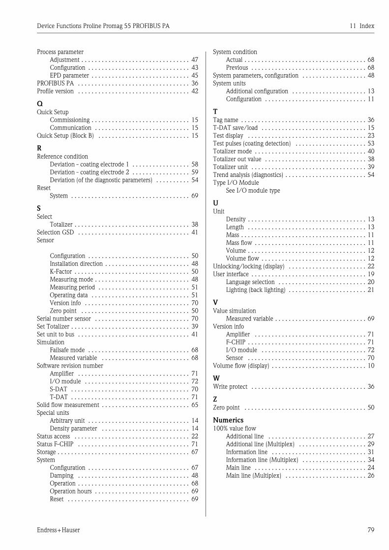
Device Functions Proline Promag 55 PROFIBUS PA 11 Index
Endress+Hauser 79
Process parameter
Adjustment . . . . . . . . . . . . . . . . . . . . . . . . . . . . . . . . 47
Configuration . . . . . . . . . . . . . . . . . . . . . . . . . . . . . . 43
EPD parameter . . . . . . . . . . . . . . . . . . . . . . . . . . . . . 45
PROFIBUS PA . . . . . . . . . . . . . . . . . . . . . . . . . . . . . . . . . 36
Profile version . . . . . . . . . . . . . . . . . . . . . . . . . . . . . . . . . 42
QQuick Setup
Commissioning . . . . . . . . . . . . . . . . . . . . . . . . . . . . . 15
Communication . . . . . . . . . . . . . . . . . . . . . . . . . . . . 15
Quick Setup (Block B) . . . . . . . . . . . . . . . . . . . . . . . . . . . 15
RReference condition
Deviation - coating electrode 1 . . . . . . . . . . . . . . . . . 58
Deviation - coating electrode 2 . . . . . . . . . . . . . . . . . 59
Deviation (of the diagnostic parameters) . . . . . . . . . . 54
Reset
System . . . . . . . . . . . . . . . . . . . . . . . . . . . . . . . . . . . 69
SSelect
Totalizer . . . . . . . . . . . . . . . . . . . . . . . . . . . . . . . . . . 38
Selection GSD . . . . . . . . . . . . . . . . . . . . . . . . . . . . . . . . . 41
Sensor
Configuration . . . . . . . . . . . . . . . . . . . . . . . . . . . . . . 50
Installation direction . . . . . . . . . . . . . . . . . . . . . . . . . 48
K-Factor . . . . . . . . . . . . . . . . . . . . . . . . . . . . . . . . . . 50
Measuring mode . . . . . . . . . . . . . . . . . . . . . . . . . . . . 48
Measuring period . . . . . . . . . . . . . . . . . . . . . . . . . . . 51
Operating data . . . . . . . . . . . . . . . . . . . . . . . . . . . . . 51
Version info . . . . . . . . . . . . . . . . . . . . . . . . . . . . . . . 70
Zero point . . . . . . . . . . . . . . . . . . . . . . . . . . . . . . . . 50
Serial number sensor . . . . . . . . . . . . . . . . . . . . . . . . . . . . 70
Set Totalizer . . . . . . . . . . . . . . . . . . . . . . . . . . . . . . . . . . . 39
Set unit to bus . . . . . . . . . . . . . . . . . . . . . . . . . . . . . . . . . 41
Simulation
Failsafe mode . . . . . . . . . . . . . . . . . . . . . . . . . . . . . . 68
Measured variable . . . . . . . . . . . . . . . . . . . . . . . . . . 68
Software revision number
Amplifier . . . . . . . . . . . . . . . . . . . . . . . . . . . . . . . . . 71
I/O module . . . . . . . . . . . . . . . . . . . . . . . . . . . . . . . 72
S-DAT . . . . . . . . . . . . . . . . . . . . . . . . . . . . . . . . . . . 70
T-DAT . . . . . . . . . . . . . . . . . . . . . . . . . . . . . . . . . . . 71
Solid flow measurement . . . . . . . . . . . . . . . . . . . . . . . . . . 65
Special units
Arbitrary unit . . . . . . . . . . . . . . . . . . . . . . . . . . . . . . 14
Density parameter . . . . . . . . . . . . . . . . . . . . . . . . . . 14
Status access . . . . . . . . . . . . . . . . . . . . . . . . . . . . . . . . . . 22
Status F-CHIP . . . . . . . . . . . . . . . . . . . . . . . . . . . . . . . . . 71
Storage . . . . . . . . . . . . . . . . . . . . . . . . . . . . . . . . . . . . . . . 67
System
Configuration . . . . . . . . . . . . . . . . . . . . . . . . . . . . . . 67
Damping . . . . . . . . . . . . . . . . . . . . . . . . . . . . . . . . . 48
Operation . . . . . . . . . . . . . . . . . . . . . . . . . . . . . . . . . 68
Operation hours . . . . . . . . . . . . . . . . . . . . . . . . . . . . 69
Reset . . . . . . . . . . . . . . . . . . . . . . . . . . . . . . . . . . . . 69
System condition
Actual . . . . . . . . . . . . . . . . . . . . . . . . . . . . . . . . . . . . 68
Previous . . . . . . . . . . . . . . . . . . . . . . . . . . . . . . . . . . 68
System parameters, configuration . . . . . . . . . . . . . . . . . . . 48
System units
Additional configuration . . . . . . . . . . . . . . . . . . . . . . 13
Configuration . . . . . . . . . . . . . . . . . . . . . . . . . . . . . . 11
TTag name . . . . . . . . . . . . . . . . . . . . . . . . . . . . . . . . . . . . . 36
T-DAT save/load . . . . . . . . . . . . . . . . . . . . . . . . . . . . . . . 15
Test display . . . . . . . . . . . . . . . . . . . . . . . . . . . . . . . . . . . 23
Test pulses (coating detection) . . . . . . . . . . . . . . . . . . . . . 53
Totalizer mode . . . . . . . . . . . . . . . . . . . . . . . . . . . . . . . . . 40
Totalizer out value . . . . . . . . . . . . . . . . . . . . . . . . . . . . . . 38
Totalizer unit . . . . . . . . . . . . . . . . . . . . . . . . . . . . . . . . . . 39
Trend analysis (diagnostics) . . . . . . . . . . . . . . . . . . . . . . . . 54
Type I/O Module
See I/O module type
UUnit
Density . . . . . . . . . . . . . . . . . . . . . . . . . . . . . . . . . . . 13
Length . . . . . . . . . . . . . . . . . . . . . . . . . . . . . . . . . . . 13
Mass . . . . . . . . . . . . . . . . . . . . . . . . . . . . . . . . . . . . . 11
Mass flow . . . . . . . . . . . . . . . . . . . . . . . . . . . . . . . . . 11
Volume . . . . . . . . . . . . . . . . . . . . . . . . . . . . . . . . . . . 12
Volume flow . . . . . . . . . . . . . . . . . . . . . . . . . . . . . . . 12
Unlocking/locking (display) . . . . . . . . . . . . . . . . . . . . . . . 22
User interface . . . . . . . . . . . . . . . . . . . . . . . . . . . . . . . . . . 19
Language selection . . . . . . . . . . . . . . . . . . . . . . . . . . 20
Lighting (back lighting) . . . . . . . . . . . . . . . . . . . . . . . 21
VValue simulation
Measured variable . . . . . . . . . . . . . . . . . . . . . . . . . . . 69
Version info
Amplifier . . . . . . . . . . . . . . . . . . . . . . . . . . . . . . . . . 71
F-CHIP . . . . . . . . . . . . . . . . . . . . . . . . . . . . . . . . . . . 71
I/O module . . . . . . . . . . . . . . . . . . . . . . . . . . . . . . . 72
Sensor . . . . . . . . . . . . . . . . . . . . . . . . . . . . . . . . . . . 70
Volume flow (display) . . . . . . . . . . . . . . . . . . . . . . . . . . . . 10
WWrite protect . . . . . . . . . . . . . . . . . . . . . . . . . . . . . . . . . . 36
ZZero point . . . . . . . . . . . . . . . . . . . . . . . . . . . . . . . . . . . . 50
Numerics100% value flow
Additional line . . . . . . . . . . . . . . . . . . . . . . . . . . . . . 27
Additional line (Multiplex) . . . . . . . . . . . . . . . . . . . . 29
Information line . . . . . . . . . . . . . . . . . . . . . . . . . . . . 31
Information line (Multiplex) . . . . . . . . . . . . . . . . . . . 34
Main line . . . . . . . . . . . . . . . . . . . . . . . . . . . . . . . . . 24
Main line (Multiplex) . . . . . . . . . . . . . . . . . . . . . . . . 26

11 Index Device Functions Proline Promag 55 PROFIBUS PA
80 Endress+Hauser

Device Functions Proline Promag 55 PROFIBUS PA 11 Index
Endress+Hauser 81

www.endress.com/worldwide
BA125D/06/en/12.07
71065434FM+SGML 6.0