Proline Promag 53 with EtherNet/IP - Endress+Hauser …€¦ · · 2014-03-28IPAddress: Ex works:...
28
Products Solutions Services SD00146D/06/EN/14.14 71249504 Supplementary documentation Proline Promag 53 Data transmission via EtherNet/IP Connection to an EtherNet/IP network and integration into a control system Using the supplementary documentation This supplementary document should only be used in conjunction with a Proline Promag 53 EtherNet/IP transmitter. Associated device documentation This document is an integral part of Operating Instructions BA117D (Proline Promag 53 Modbus RS485). It acts as a supplement to BA117D by providing information on using the transmitter in an EtherNet/IP network.
Transcript of Proline Promag 53 with EtherNet/IP - Endress+Hauser …€¦ · · 2014-03-28IPAddress: Ex works:...

Products Solutions ServicesSD00146D/06/EN/14.1471249504
Supplementary documentationProline Promag 53Data transmission via EtherNet/IP
Connection to an EtherNet/IP network and integration into a control system
Using the supplementary documentationThis supplementary document should only be used in conjunction with a Proline Promag 53 EtherNet/IP transmitter.
Associated device documentationThis document is an integral part of Operating Instructions BA117D (Proline Promag 53 Modbus RS485). It acts as a supplement to BA117D by providing information on using the transmitter in an EtherNet/IP network.
Proline Promag 53 mit EtherNet/IP
2 Endress+Hauser
Table of contents
System design . . . . . . . . . . . . . . . . . . . . . . . . . . . . . . . . . .3Measuring device . . . . . . . . . . . . . . . . . . . . . . . . . . . . . . . . . . . . . . 3Dual Ethernet module . . . . . . . . . . . . . . . . . . . . . . . . . . . . . . . . . . 3Connection versions . . . . . . . . . . . . . . . . . . . . . . . . . . . . . . . . . . . 3Connection label . . . . . . . . . . . . . . . . . . . . . . . . . . . . . . . . . . . . . . 4
Dual Ethernet module . . . . . . . . . . . . . . . . . . . . . . . . . . .5Configuration . . . . . . . . . . . . . . . . . . . . . . . . . . . . . . . . . . . . . . . . . 5Status light emitting diodes (LED) . . . . . . . . . . . . . . . . . . . . . . . 5DIP switches for hardware addressing . . . . . . . . . . . . . . . . . . . . 5DIP switches to reset software addressing . . . . . . . . . . . . . . . . . 6
Connection values . . . . . . . . . . . . . . . . . . . . . . . . . . . . . . .6Dual Ethernet module connection . . . . . . . . . . . . . . . . . . . . . . . . 6Power supply . . . . . . . . . . . . . . . . . . . . . . . . . . . . . . . . . . . . . . . . . 6Ethernet port . . . . . . . . . . . . . . . . . . . . . . . . . . . . . . . . . . . . . . . . . 6M12 fieldbus connector . . . . . . . . . . . . . . . . . . . . . . . . . . . . . . . . 7RJ45 connector . . . . . . . . . . . . . . . . . . . . . . . . . . . . . . . . . . . . . . . . 7Cable entries . . . . . . . . . . . . . . . . . . . . . . . . . . . . . . . . . . . . . . . . . . 7
Grounding and shielding . . . . . . . . . . . . . . . . . . . . . . . . .8EMC PG cable gland . . . . . . . . . . . . . . . . . . . . . . . . . . . . . . . . . . . 8Conduit cabling . . . . . . . . . . . . . . . . . . . . . . . . . . . . . . . . . . . . . . . 8
Webserver . . . . . . . . . . . . . . . . . . . . . . . . . . . . . . . . . . . . .8PC/laptop settings . . . . . . . . . . . . . . . . . . . . . . . . . . . . . . . . . . . . . 8
Configuring the IP address . . . . . . . . . . . . . . . . . . . . . . .9Hardware addressing . . . . . . . . . . . . . . . . . . . . . . . . . . . . . . . . . . 9Software addressing . . . . . . . . . . . . . . . . . . . . . . . . . . . . . . . . . . 10DHCP client . . . . . . . . . . . . . . . . . . . . . . . . . . . . . . . . . . . . . . . . . . 10Local operation . . . . . . . . . . . . . . . . . . . . . . . . . . . . . . . . . . . . . . 11
Webserver menus . . . . . . . . . . . . . . . . . . . . . . . . . . . . . 12Overview of the Webserver menus . . . . . . . . . . . . . . . . . . . . . . 12Login . . . . . . . . . . . . . . . . . . . . . . . . . . . . . . . . . . . . . . . . . . . . . . . 12User Management . . . . . . . . . . . . . . . . . . . . . . . . . . . . . . . . . . . . 12Info . . . . . . . . . . . . . . . . . . . . . . . . . . . . . . . . . . . . . . . . . . . . . . . . 13Overview . . . . . . . . . . . . . . . . . . . . . . . . . . . . . . . . . . . . . . . . . . . . 13Network Configuration . . . . . . . . . . . . . . . . . . . . . . . . . . . . . . . . 14Data Map . . . . . . . . . . . . . . . . . . . . . . . . . . . . . . . . . . . . . . . . . . . 15Ethernet Diagnostics . . . . . . . . . . . . . . . . . . . . . . . . . . . . . . . . . . 16Device Configuration . . . . . . . . . . . . . . . . . . . . . . . . . . . . . . . . . . 17Firmware Update . . . . . . . . . . . . . . . . . . . . . . . . . . . . . . . . . . . . . 17Parameter Up-/Download . . . . . . . . . . . . . . . . . . . . . . . . . . . . . 17
Technical data . . . . . . . . . . . . . . . . . . . . . . . . . . . . . . . . 17
Configuring the Data Map via the Webserver . . . . . 18
Integrating into a control system . . . . . . . . . . . . . . . . 20Electronic data sheet file (EDS) . . . . . . . . . . . . . . . . . . . . . . . . . 20
Integration into a Rockwell Automation control system . . . . . . . . . . . . . . . . . . . . . . . . . . . . . . . . 20Installing the electronic data sheet file (EDS) . . . . . . . . . . . . . 20Installation Add On Profile (AOP) incl. EDS . . . . . . . . . . . . . . . 20Implementation in the Rockwell EtherNet/IP architecture . . 20Download the settings . . . . . . . . . . . . . . . . . . . . . . . . . . . . . . . . 25Displaying the measured, input and output values in online mode . . . . . . . . . . . . . . . . . . . . . . . . . . . . . . . . . . . . . . . . 26

Proline Promag 53 mit EtherNet/IP
Endress+Hauser 3
System design
Measuring device The measuring device has a dual Ethernet module to connect it to an EtherNet/IP network and for connecting to a Webserver integrated in the measuring device. It uses the EtherNet/IP communication protocol (Ethernet Industrial Protocol) in accordance with the ODVA specification.
Transmitters with a dual Ethernet module are marked "EtherNet/IP" on the nameplate.
Dual Ethernet module
Connection versions There are primarily three ways to connect the measuring device.
Transmitter cable entries
Connection version 1
If the network cable is routed directly into the measuring device through the cable entry, an RJ45 plug must be connected to the network cable.
! Note! An RJ45 plug does not form part of the delivery.
" Caution! If this connection version is used, attention must be paid to the grounding and shielding of the measuring device ä 8.
Connection version 2 and 3
If the measuring device is connected using one or two fieldbus connectors, the device is supplied with one or two 4-pin M12 ports (in accordance with IEC 61076-2-10). You require M12 connectors to connect the device (e.g. Binder Ethernet Connector, Series 825, Article No: 99-3729-810-04).
! Note! M12 connectors do not form part of the delivery.
Structure of the dual Ethernet module
a Ethernet port 1 for EtherNet/IP network or Webserver
b Ethernet port 2 for EtherNet/IP network or Webserver
c Status light emitting diodes (LED)
d DIP switches for hardware addressing
e DIP switches to reset software addressing
f Power supply connection
g Port for service interface FXA193 (FieldCare)a
b
c d
e
g f
a
b
c
Connection version 1 Connection version 2 Connection version 3
a Ethernet via cable entry/cable gland
Ethernet via fieldbus connector
Ethernet via fieldbus connector
b Dummy plug Dummy plugEthernet via fieldbus connector
c Power supply via cable entry/cable gland
Power supply via cable entry/cable gland
Power supply via cable entry/cable gland

Proline Promag 53 mit EtherNet/IP
4 Endress+Hauser
Connecting to the EtherNet/IP network and accessing the Webserver
The measuring device has a dual Ethernet module with two Ethernet ports. A connection to the EtherNet/IP network, as well as a connection to the Webserver, can be established through the two Ethernet ports. The ports are assigned using the individual IP address.
The dual Ethernet module has an integrated switch that processes the Ethernet data packets on a "store and forward" basis. It can manage up to 256 MAC addresses in its source address table (SAT).
With regard to connection version 3, you can access the Webserver of the measuring device without having to open the device if a connection to the EtherNet/IP network has already been established.
In the case of connection versions 1 and 2, if a connection to the EtherNet/IP network has already been established you can connect to the Webserver by connecting a PC/laptop directly to the dual Ethernet module. The connection compartment of the measuring device must be opened for this purpose, however.
# Warning! Heed the safety instructions in the Operating Instructions when opening the connection compartment!
Connection label A connection label in the cover of the connection compartment provides information on the default IP addresses and the device-specific MAC addresses. If a new IP address is assigned, this can be documented on the connection label.
Connection label (example)
Communication:
Drivers:
Device SW:
1.01
1.01.00
Ethernet
Date: 1. DEC 2010
Ex–works / ab Werk / réglages usine
Observer manuel d'instruction
See operating manualBetriebsanleitung beachten
EthernetNetwork
12345678912Ser.No.:
319475-0001B
Update 1 Update 2
Supply / Versorgung /
Tension d'alimentation
Webserver
N / L-
PE
L1 / L+
1 2
192.168.212.212Ex works:
Update:IP Address:
00:07:05:10:01:1FEx works:
Update:MAC Address:
192.168.212.213Ex works:
Update:IP Address:
00:07:05:10:01:1GEx works:
Update:MAC Address:
(WEA)
Proline Promag 53 mit EtherNet/IP
Endress+Hauser 5
Dual Ethernet module
Configuration
Status light emitting diodes (LED)
DIP switches for hardware addressing
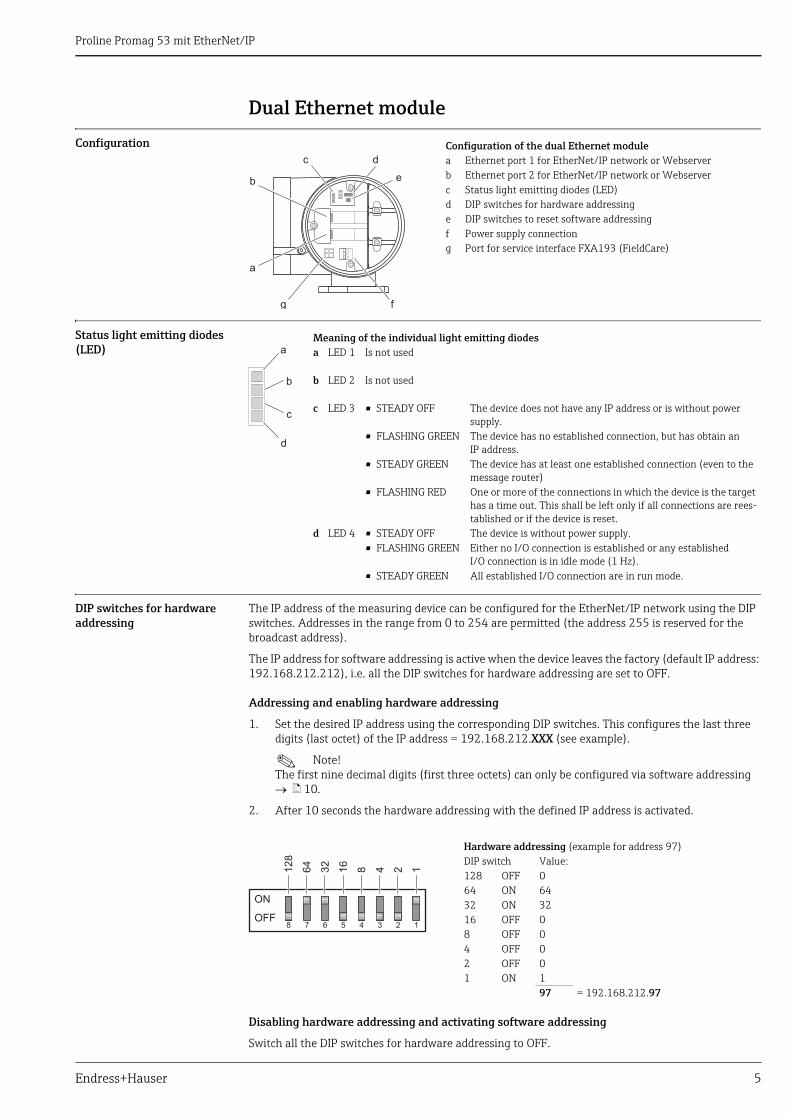
The IP address of the measuring device can be configured for the EtherNet/IP network using the DIP switches. Addresses in the range from 0 to 254 are permitted (the address 255 is reserved for the broadcast address).
The IP address for software addressing is active when the device leaves the factory (default IP address: 192.168.212.212), i.e. all the DIP switches for hardware addressing are set to OFF.
Addressing and enabling hardware addressing
1. Set the desired IP address using the corresponding DIP switches. This configures the last three digits (last octet) of the IP address = 192.168.212.XXX (see example).
! Note! The first nine decimal digits (first three octets) can only be configured via software addressing ä 10.
2. After 10 seconds the hardware addressing with the defined IP address is activated.
Disabling hardware addressing and activating software addressing
Switch all the DIP switches for hardware addressing to OFF.
Configuration of the dual Ethernet modulea Ethernet port 1 for EtherNet/IP network or Webserverb Ethernet port 2 for EtherNet/IP network or Webserverc Status light emitting diodes (LED)d DIP switches for hardware addressinge DIP switches to reset software addressingf Power supply connectiong Port for service interface FXA193 (FieldCare)
a
b
c d
e
g f
Meaning of the individual light emitting diodesa LED 1 Is not used
b LED 2 Is not used
c LED 3 • STEADY OFF The device does not have any IP address or is without power supply.
• FLASHING GREEN The device has no established connection, but has obtain an IP address.
• STEADY GREEN The device has at least one established connection (even to the message router)
• FLASHING RED One or more of the connections in which the device is the target has a time out. This shall be left only if all connections are rees-tablished or if the device is reset.
d LED 4 • STEADY OFF The device is without power supply.• FLASHING GREEN Either no I/O connection is established or any established
I/O connection is in idle mode (1 Hz).• STEADY GREEN All established I/O connection are in run mode.
a
b
c
d
Hardware addressing (example for address 97)DIP switch Value:128 OFF 064 ON 6432 ON 3216 OFF 08 OFF 04 OFF 02 OFF 01 ON 1
97 = 192.168.212.97
12
8
ON
OFF
64
32
16
8 4 2 1
8 7 6 5 4 3 2 1
Proline Promag 53 mit EtherNet/IP
6 Endress+Hauser
DIP switches to reset software addressing
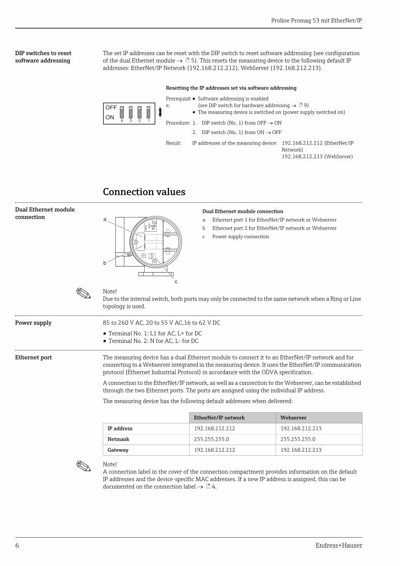
The set IP addresses can be reset with the DIP switch to reset software addressing (see configuration of the dual Ethernet module ä 5). This resets the measuring device to the following default IP addresses: EtherNet/IP Network (192.168.212.212), WebServer (192.168.212.213).
Connection values
Dual Ethernet module connection
! Note! Due to the internal switch, both ports may only be connected to the same network when a Ring or Line topology is used.
Power supply 85 to 260 V AC, 20 to 55 V AC,16 to 62 V DC
• Terminal No. 1: L1 for AC, L+ for DC• Terminal No. 2: N for AC, L- for DC
Ethernet port The measuring device has a dual Ethernet module to connect it to an EtherNet/IP network and for connecting to a Webserver integrated in the measuring device. It uses the EtherNet/IP communication protocol (Ethernet Industrial Protocol) in accordance with the ODVA specification.
A connection to the EtherNet/IP network, as well as a connection to the Webserver, can be established through the two Ethernet ports. The ports are assigned using the individual IP address.
The measuring device has the following default addresses when delivered:
! Note! A connection label in the cover of the connection compartment provides information on the default IP addresses and the device-specific MAC addresses. If a new IP address is assigned, this can be documented on the connection label ä 4.
Resetting the IP addresses set via software addressing
Prerequisite:
• Software addressing is enabled (see DIP switch for hardware addressing ä 9)
• The measuring device is switched on (power supply switched on)
Procedure: 1. DIP switch (No. 1) from OFF ON
2. DIP switch (No. 1) from ON OFF
Result: IP addresses of the measuring device: 192.168.212.212 (EtherNet/IP Network)192.168.212.213 (WebServer)
OFF
ON4 3 2 1
Dual Ethernet module connection
a Ethernet port 1 for EtherNet/IP network or Webserver
b Ethernet port 2 for EtherNet/IP network or Webserver
c Power supply connection
b
a
c
EtherNet/IP network Webserver
IP address 192.168.212.212 192.168.212.213
Netmask 255.255.255.0 255.255.255.0
Gateway 192.168.212.212 192.168.212.213
Proline Promag 53 mit EtherNet/IP
Endress+Hauser 7
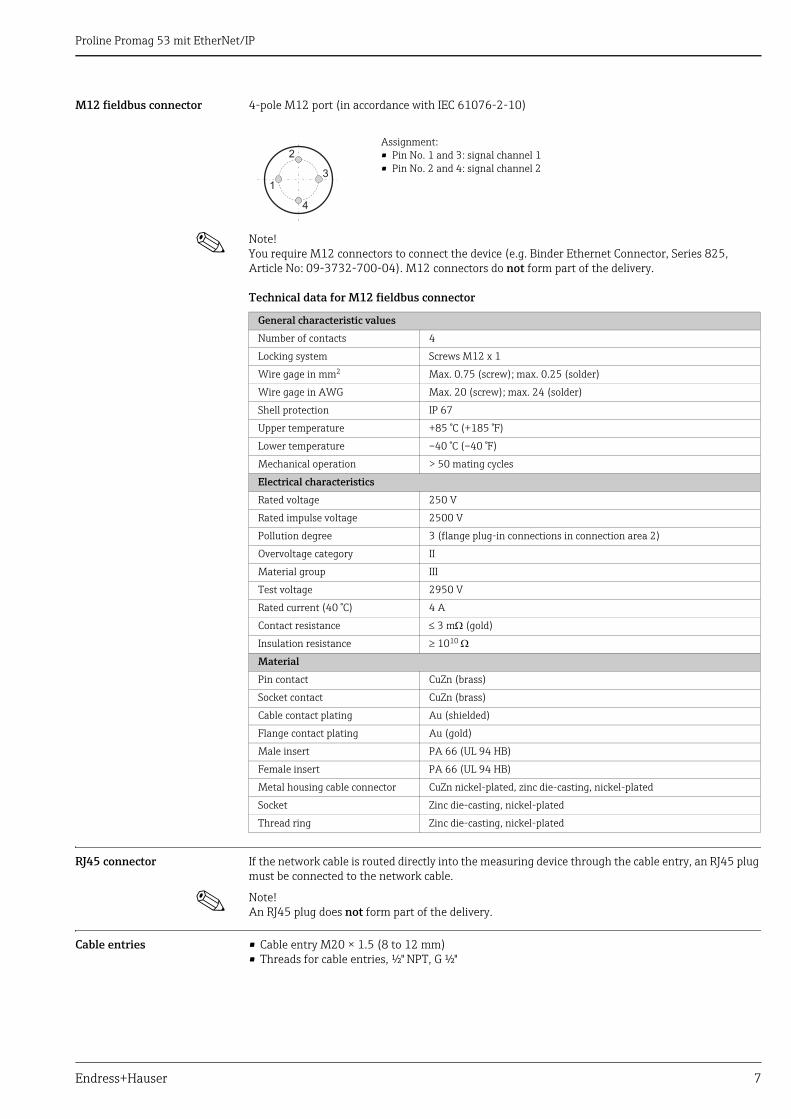
M12 fieldbus connector 4-pole M12 port (in accordance with IEC 61076-2-10)
! Note! You require M12 connectors to connect the device (e.g. Binder Ethernet Connector, Series 825, Article No: 09-3732-700-04). M12 connectors do not form part of the delivery.
Technical data for M12 fieldbus connector
RJ45 connector If the network cable is routed directly into the measuring device through the cable entry, an RJ45 plug must be connected to the network cable.
! Note! An RJ45 plug does not form part of the delivery.
Cable entries • Cable entry M20 × 1.5 (8 to 12 mm)• Threads for cable entries, ½" NPT, G ½"
Assignment:• Pin No. 1 and 3: signal channel 1• Pin No. 2 and 4: signal channel 2
13
2
4
General characteristic values
Number of contacts 4
Locking system Screws M12 x 1
Wire gage in mm2 Max. 0.75 (screw); max. 0.25 (solder)
Wire gage in AWG Max. 20 (screw); max. 24 (solder)
Shell protection IP 67
Upper temperature +85 °C (+185 °F)
Lower temperature –40 °C (–40 °F)
Mechanical operation > 50 mating cycles
Electrical characteristics
Rated voltage 250 V
Rated impulse voltage 2500 V
Pollution degree 3 (flange plug-in connections in connection area 2)
Overvoltage category II
Material group III
Test voltage 2950 V
Rated current (40 °C) 4 A
Contact resistance 3 m (gold)
Insulation resistance 1010
Material
Pin contact CuZn (brass)
Socket contact CuZn (brass)
Cable contact plating Au (shielded)
Flange contact plating Au (gold)
Male insert PA 66 (UL 94 HB)
Female insert PA 66 (UL 94 HB)
Metal housing cable connector CuZn nickel-plated, zinc die-casting, nickel-plated
Socket Zinc die-casting, nickel-plated
Thread ring Zinc die-casting, nickel-plated
Proline Promag 53 mit EtherNet/IP
8 Endress+Hauser
Grounding and shieldingIf the EtherNet/IP cable is routed directly into the measuring device through the cable entry (a fieldbus connector is not used), correct grounding and shielding must be ensured. This is required to guarantee electromagnetic compatibility (EMC). The following grounding and shielding options are available:
EMC PG cable gland Users can ensure correct grounding of the shield at the cable entry by using a standard armored thread (PG) cable gland that meets EMC requirements.
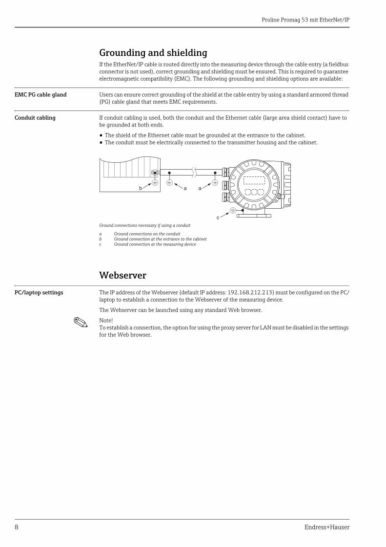
Conduit cabling If conduit cabling is used, both the conduit and the Ethernet cable (large area shield contact) have to be grounded at both ends.
• The shield of the Ethernet cable must be grounded at the entrance to the cabinet.• The conduit must be electrically connected to the transmitter housing and the cabinet.
Ground connections necessary if using a conduit
a Ground connections on the conduitb Ground connection at the entrance to the cabinetc Ground connection at the measuring device
Webserver
PC/laptop settings The IP address of the Webserver (default IP address: 192.168.212.213) must be configured on the PC/laptop to establish a connection to the Webserver of the measuring device.
The Webserver can be launched using any standard Web browser.
! Note! To establish a connection, the option for using the proxy server for LAN must be disabled in the settings for the Web browser.
a ab
c
Proline Promag 53 mit EtherNet/IP
Endress+Hauser 9
Configuring the IP address
Hardware addressing The IP address of the measuring device can be configured for the EtherNet/IP network via the DIP switches for hardware addressing (see configuration of dual Ethernet module ä 5). Addresses in the range from 0 to 254 are permitted (the address 255 is reserved for the broadcast address).
The IP address for software addressing is active when the device leaves the factory (default IP address: 192.168.212.212), i.e. all the DIP switches for hardware addressing are set to OFF.
Addressing and enabling hardware addressing
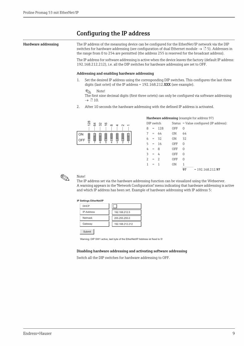
1. Set the desired IP address using the corresponding DIP switches. This configures the last three digits (last octet) of the IP address = 192.168.212.XXX (see example).
! Note! The first nine decimal digits (first three octets) can only be configured via software addressing ä 10.
2. After 10 seconds the hardware addressing with the defined IP address is activated.
! Note! The IP address set via the hardware addressing function can be visualized using the Webserver. A warning appears in the "Network Configuration" menu indicating that hardware addressing is active and which IP address has been set. Example of hardware addressing with IP address 5:
Disabling hardware addressing and activating software addressing
Switch all the DIP switches for hardware addressing to OFF.
Hardware addressing (example for address 97)
DIP switch Status = Value configured (IP address):
8 = 128 OFF 0
7 = 64 ON 64
6 = 32 ON 32
5 = 16 OFF 0
4 = 8 OFF 0
3 = 4 OFF 0
2 = 2 OFF 0
1 = 1 ON 1
97 = 192.168.212.97
12
8
ON
OFF
64
32
16
8 4 2 1
8 7 6 5 4 3 2 1
DHCP
IP Settings EtherNet/IP
IP-Address
Netmask
Gateway
Warning: DIP SW1 active, last byte of the EtherNet/IP Address ist fixed to 5!
Submit
192.168.212.5
255.255.255.0
192.168.212.212

Proline Promag 53 mit EtherNet/IP
10 Endress+Hauser
Software addressing Software addressing is performed in the "Network Configuration" menu of the Webserver. Both the IP address for the Webserver and the IP address for the EtherNet/IP network can be configured.
The measuring device has the following default addresses when delivered:
Addresses in the range from 0 to 254 are permitted (the address 255 is reserved for the broadcast address).
Software addressing via the "Network Configuration" menu
! Note! • Software addressing is disabled if hardware addressing is activated ä 9.• When changing from software addressing to hardware addressing, the first nine digits (first three
octets) that were configured using software addressing, remain unchanged.• A reset of the software addressing to the default setting is possible ä 6.
DHCP client If a DHCP server is used within the EtherNet/IP network, the IP address, gateway and subnet mask are set automatically when the DHCP client function is enabled. The MAC address of the measuring device is used for identification purposes (see also the connection label on ä 4).
The DHCP client function is enabled in the "Network Configuration" menu.
The measuring device has the following DHCP default settings when delivered:
! Note! The DHCP client function is disabled if hardware addressing is enabled ä 9.
EtherNet/IP network Webserver
IP address 192.168.212.212 192.168.212.213
Netmask 255.255.255.0 255.255.255.0
Gateway 192.168.212.212 192.168.212.213
EtherNet/IP network Webserver
DHCP Yes (enabled) No (disabled)

Proline Promag 53 mit EtherNet/IP
Endress+Hauser 11
Local operation The address configuration for the measuring device is displayed via the local display.
Displaying the address configuration via the local display
The individual addressing parameters are assigned as follows:
- + E
Esc
> 3s+
Esc
–
–
+
…
BASIC FUNCTION
…
ETHERNET
E
–
+
…
CONFIGURATION
E
–
+
E
E IP ADDRESS 1
SUBNETMASK 1
GATEWAY 1
IP ADDRESS 2
SUBNETMASK 2
GATEWAY 2
E
–
+
…
SUPERVISION
…
VERSION-INFO
E
–
+
…
E
–
+E SW-REV. SUB A/E
MAC ADD. 1
MAC ADD. 2
E
ETHERNET
Parameter Assignment
IP ADDRESS 1 EtherNet/IP network
SUBNETMASK 1
GATEWAY 1
MAC ADD. 1
IP ADDRESS 2 Webserver
SUBNETMASK 2
GATEWAY 2
MAC ADD. 2
Proline Promag 53 mit EtherNet/IP
12 Endress+Hauser
Webserver menus
Overview of the Webserver menus
The Webserver has the following menus:
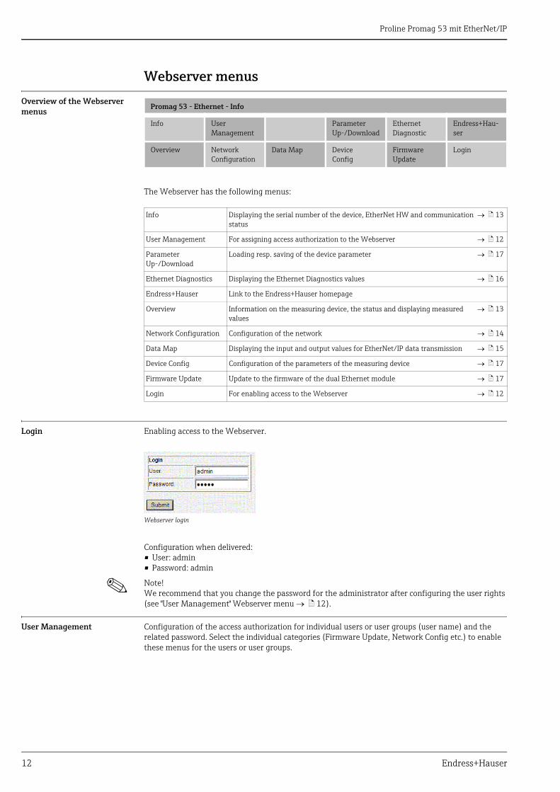
Login Enabling access to the Webserver.
Webserver login
Configuration when delivered:• User: admin• Password: admin
! Note! We recommend that you change the password for the administrator after configuring the user rights (see "User Management" Webserver menu ä 12).
User Management Configuration of the access authorization for individual users or user groups (user name) and the related password. Select the individual categories (Firmware Update, Network Config etc.) to enable these menus for the users or user groups.
Promag 53 - Ethernet - Info
Info User Management
Parameter Up-/Download
EthernetDiagnostic
Endress+Hau-ser
Overview Network Configuration
Data Map Device Config
FirmwareUpdate
Login
Info Displaying the serial number of the device, EtherNet HW and communication status
ä 13
User Management For assigning access authorization to the Webserver ä 12
Parameter Up-/Download
Loading resp. saving of the device parameter ä 17
Ethernet Diagnostics Displaying the Ethernet Diagnostics values ä 16
Endress+Hauser Link to the Endress+Hauser homepage
Overview Information on the measuring device, the status and displaying measured values
ä 13
Network Configuration Configuration of the network ä 14
Data Map Displaying the input and output values for EtherNet/IP data transmission ä 15
Device Config Configuration of the parameters of the measuring device ä 17
Firmware Update Update to the firmware of the dual Ethernet module ä 17
Login For enabling access to the Webserver ä 12

Proline Promag 53 mit EtherNet/IP
Endress+Hauser 13
Info Displays the serial number of the measuring device, information on the Ethernet hardware and of the current communication status:
Info menu
Overview Displays information on the measuring device, the measured values and the current system condition of the measuring device:
Overview menu
Proline Promag 53 mit EtherNet/IP
14 Endress+Hauser
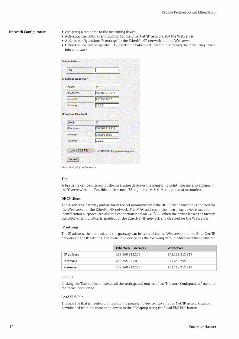
Network Configuration • Assigning a tag name to the measuring device.• Activating the DHCP client function for the EtherNet/IP network and the Webserver• Address configuration: IP settings for the EtherNet/IP network and the Webserver• Uploading the device-specific EDS (Electronic Data Sheet) file for integrating the measuring device
into a network
Network Configuration menu
Tag
A tag name can be entered for the measuring device or the measuring point. The tag also appears in the "Overview" menu. Possible entries: max. 32-digit text (A-Z, 0-9, +,-, punctuation marks).
DHCP client
The IP address, gateway and netmask are set automatically if the DHCP client function is enabled for the Web server or the EtherNet/IP network. The MAC address of the measuring device is used for identification purposes (see also the connection label on ä 4). When the device leaves the factory, the DHCP client function is enabled for the EtherNet/IP network and disabled for the Webserver.
IP settings
The IP address, the netmask and the gateway can be entered for the Webserver and the EtherNet/IP network via the IP settings. The measuring device has the following default addresses when delivered:
Submit
Clicking the "Submit" button sends all the settings and entries of the "Network Configuration" menu to the measuring device.
Load EDS File
The EDS file that is needed to integrate the measuring device into an EtherNet/IP network can be downloaded from the measuring device to the PC/laptop using the "Load EDS File" button.
EtherNet/IP network Webserver
IP address 192.168.212.212 192.168.212.213
Netmask 255.255.255.0 255.255.255.0
Gateway 192.168.212.212 192.168.212.213
Proline Promag 53 mit EtherNet/IP
Endress+Hauser 15
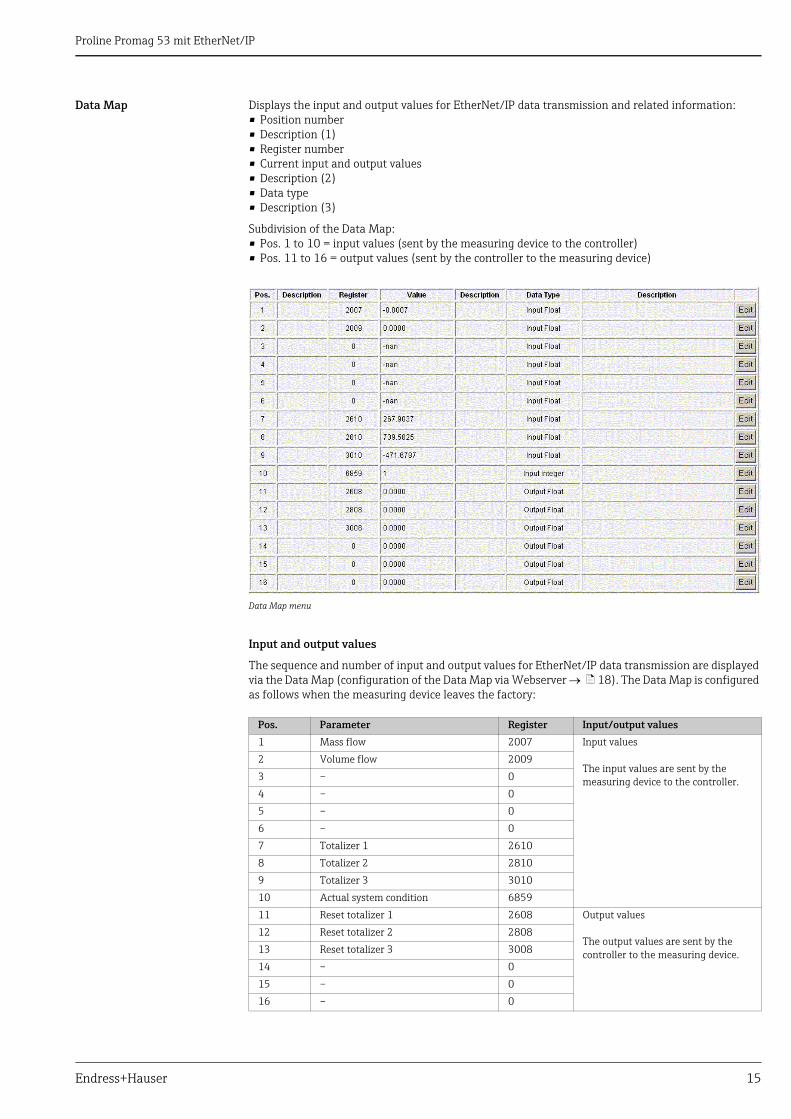
Data Map Displays the input and output values for EtherNet/IP data transmission and related information:• Position number• Description (1)• Register number• Current input and output values• Description (2) • Data type• Description (3)
Subdivision of the Data Map:• Pos. 1 to 10 = input values (sent by the measuring device to the controller)• Pos. 11 to 16 = output values (sent by the controller to the measuring device)
Data Map menu
Input and output values
The sequence and number of input and output values for EtherNet/IP data transmission are displayed via the Data Map (configuration of the Data Map via Webserver ä 18). The Data Map is configured as follows when the measuring device leaves the factory:
Pos. Parameter Register Input/output values
1 Mass flow 2007 Input values
The input values are sent by the measuring device to the controller.
2 Volume flow 2009
3 – 0
4 – 0
5 – 0
6 – 0
7 Totalizer 1 2610
8 Totalizer 2 2810
9 Totalizer 3 3010
10 Actual system condition 6859
11 Reset totalizer 1 2608 Output values
The output values are sent by the controller to the measuring device.
12 Reset totalizer 2 2808
13 Reset totalizer 3 3008
14 – 0
15 – 0
16 – 0
Proline Promag 53 mit EtherNet/IP
16 Endress+Hauser
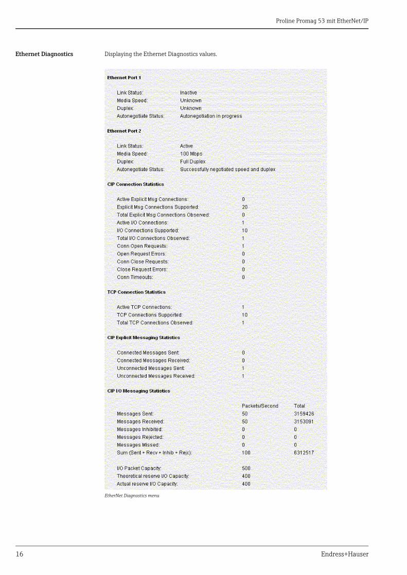
Ethernet Diagnostics Displaying the Ethernet Diagnostics values.
EtherNet Diagnostics menu
Proline Promag 53 mit EtherNet/IP
Endress+Hauser 17
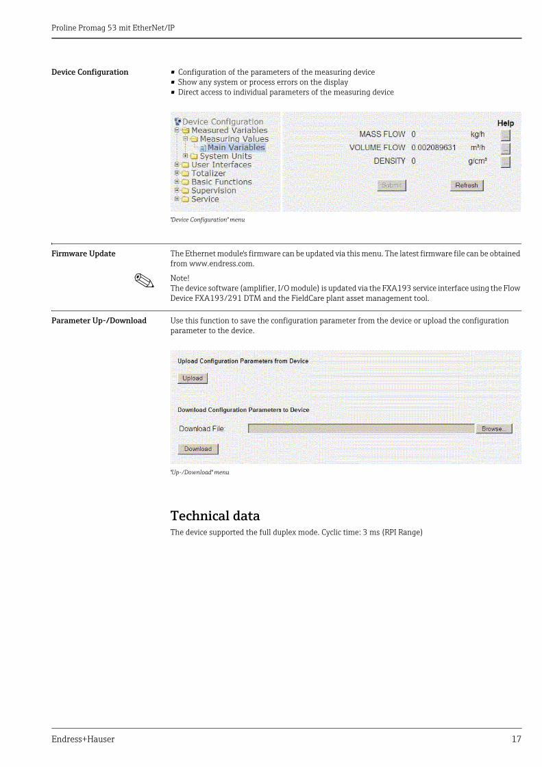
Device Configuration • Configuration of the parameters of the measuring device• Show any system or process errors on the display• Direct access to individual parameters of the measuring device
"Device Configuration" menu
Firmware Update The Ethernet module's firmware can be updated via this menu. The latest firmware file can be obtained from www.endress.com.
! Note! The device software (amplifier, I/O module) is updated via the FXA193 service interface using the Flow Device FXA193/291 DTM and the FieldCare plant asset management tool.
Parameter Up-/Download Use this function to save the configuration parameter from the device or upload the configuration parameter to the device.
"Up-/Download" menu
Technical dataThe device supported the full duplex mode. Cyclic time: 3 ms (RPI Range)
Proline Promag 53 mit EtherNet/IP
18 Endress+Hauser
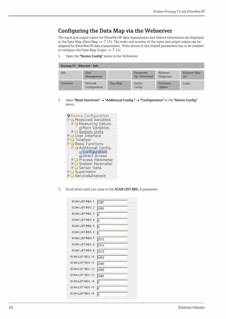
Configuring the Data Map via the WebserverThe input and output values for EtherNet/IP data transmission and related information are displayed in the Data Map (Data Map ä 15). The order and number of the input and output values can be adapted for EtherNet/IP data transmission. Write access to the related parameters has to be enabled to configure the Data Map (Login ä 12).
1. Open the "Device Config" menu in the Webserver.
2. Open "Basic functions" "Additional Config." "Configuration" in the "Device Config" menu.
3. Scroll down until you come to the SCAN LIST REG. 1 parameter.
Promag 53 - Ethernet - Info
Info User Management
Parameter Up-/Download
EthernetDiagnostic
Endress+Hau-ser
Overview Network Configuration
Data Map Device Config
FirmwareUpdate
Login
Proline Promag 53 mit EtherNet/IP
Endress+Hauser 19
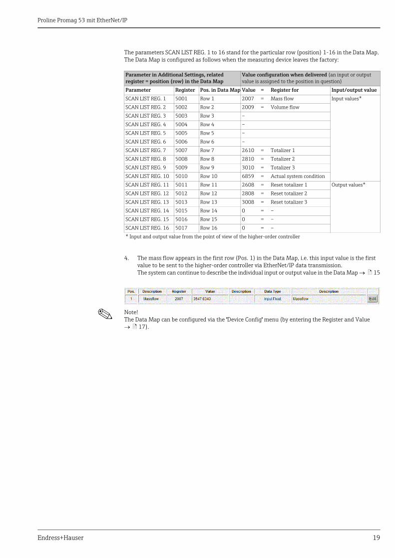
The parameters SCAN LIST REG. 1 to 16 stand for the particular row (position) 1-16 in the Data Map. The Data Map is configured as follows when the measuring device leaves the factory:
4. The mass flow appears in the first row (Pos. 1) in the Data Map, i.e. this input value is the first value to be sent to the higher-order controller via EtherNet/IP data transmission.The system can continue to describe the individual input or output value in the Data Map ä 15
! Note! The Data Map can be configured via the "Device Config" menu (by entering the Register and Value ä 17).
Parameter in Additional Settings, related register = position (row) in the Data Map
Value configuration when delivered (an input or output value is assigned to the position in question)
Parameter Register Pos. in Data Map Value = Register for Input/output value
SCAN LIST REG. 1 5001 Row 1 2007 = Mass flow Input values*
SCAN LIST REG. 2 5002 Row 2 2009 = Volume flow
SCAN LIST REG. 3 5003 Row 3 –
SCAN LIST REG. 4 5004 Row 4 –
SCAN LIST REG. 5 5005 Row 5 –
SCAN LIST REG. 6 5006 Row 6 –
SCAN LIST REG. 7 5007 Row 7 2610 = Totalizer 1
SCAN LIST REG. 8 5008 Row 8 2810 = Totalizer 2
SCAN LIST REG. 9 5009 Row 9 3010 = Totalizer 3
SCAN LIST REG. 10 5010 Row 10 6859 = Actual system condition
SCAN LIST REG. 11 5011 Row 11 2608 = Reset totalizer 1 Output values*
SCAN LIST REG. 12 5012 Row 12 2808 = Reset totalizer 2
SCAN LIST REG. 13 5013 Row 13 3008 = Reset totalizer 3
SCAN LIST REG. 14 5015 Row 14 0 = –
SCAN LIST REG. 15 5016 Row 15 0 = –
SCAN LIST REG. 16 5017 Row 16 0 = –
* Input and output value from the point of view of the higher-order controller
Proline Promag 53 mit EtherNet/IP
20 Endress+Hauser
Integrating into a control system
Electronic data sheet file (EDS)
The EDS file required for the installation can be loaded directly from the device via the Webserver ("Network Configuration" menu, Load EDS File ä 14). Alternatively, the file can also be downloaded from the Endress+Hauser Website (www.endress.com).
Integration into a Rockwell Automation control systemIntegration into the Rockwell Automation control system RSLogix5000.
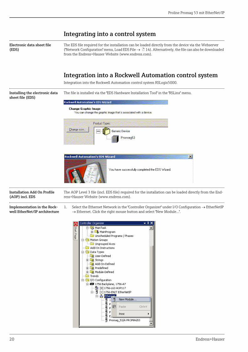
Installing the electronic data sheet file (EDS)
The file is installed via the "EDS Hardware Installation Tool" in the "RSLinx" menu.
Installation Add On Profile (AOP) incl. EDS
The AOP Level 3 file (incl. EDS file) required for the installation can be loaded directly from the End-ress+Hauser Website (www.endress.com).
Implementation in the Rock-well EtherNet/IP architecture
1. Select the Ethernet Network in the "Controller Organizer" under I/O Configuration EtherNetIP Ethernet. Click the right mouse button and select "New Module…".
Proline Promag 53 mit EtherNet/IP
Endress+Hauser 21
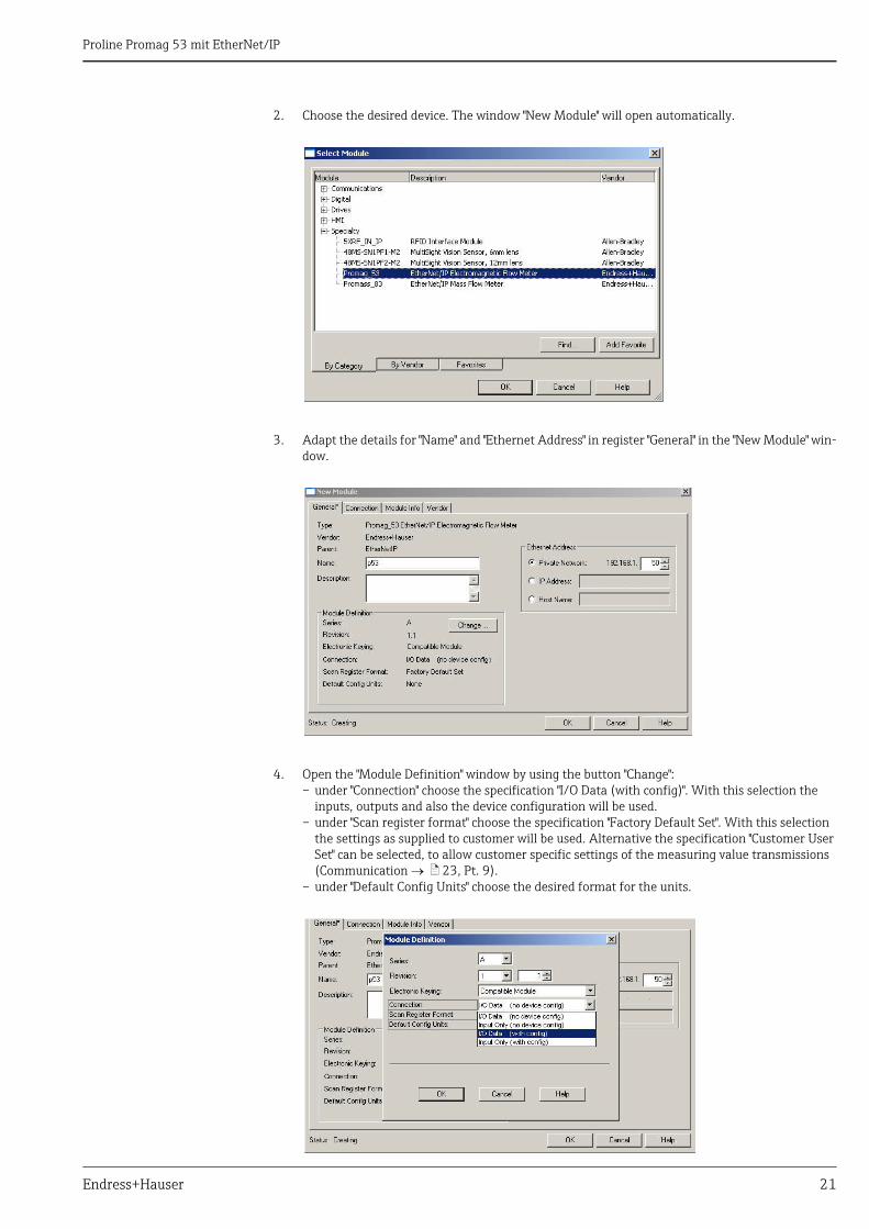
2. Choose the desired device. The window "New Module" will open automatically.
3. Adapt the details for "Name" and "Ethernet Address" in register "General" in the "New Module" win-dow.
4. Open the "Module Definition" window by using the button "Change":– under "Connection" choose the specification "I/O Data (with config)". With this selection the
inputs, outputs and also the device configuration will be used.– under "Scan register format" choose the specification "Factory Default Set". With this selection
the settings as supplied to customer will be used. Alternative the specification "Customer User Set" can be selected, to allow customer specific settings of the measuring value transmissions (Communication ä 23, Pt. 9).
– under "Default Config Units" choose the desired format for the units.
Proline Promag 53 mit EtherNet/IP
22 Endress+Hauser
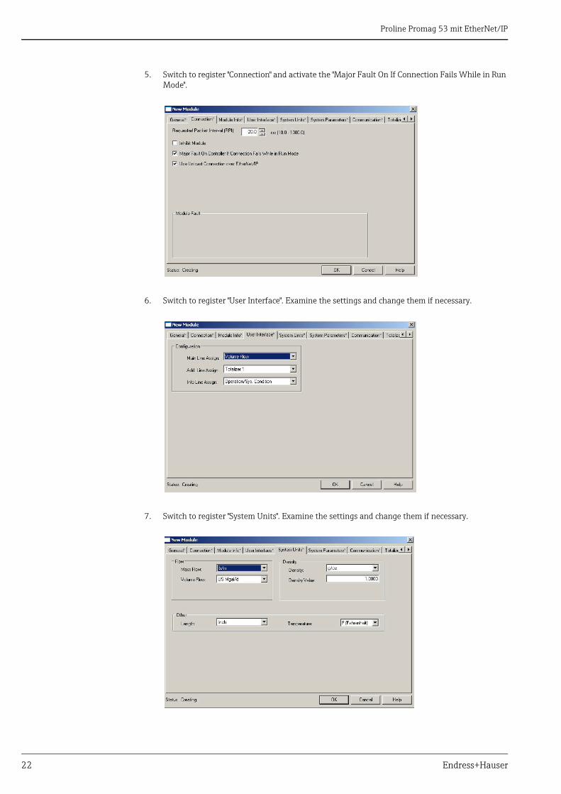
5. Switch to register "Connection" and activate the "Major Fault On If Connection Fails While in Run Mode".
6. Switch to register "User Interface". Examine the settings and change them if necessary.
7. Switch to register "System Units". Examine the settings and change them if necessary.
Proline Promag 53 mit EtherNet/IP
Endress+Hauser 23
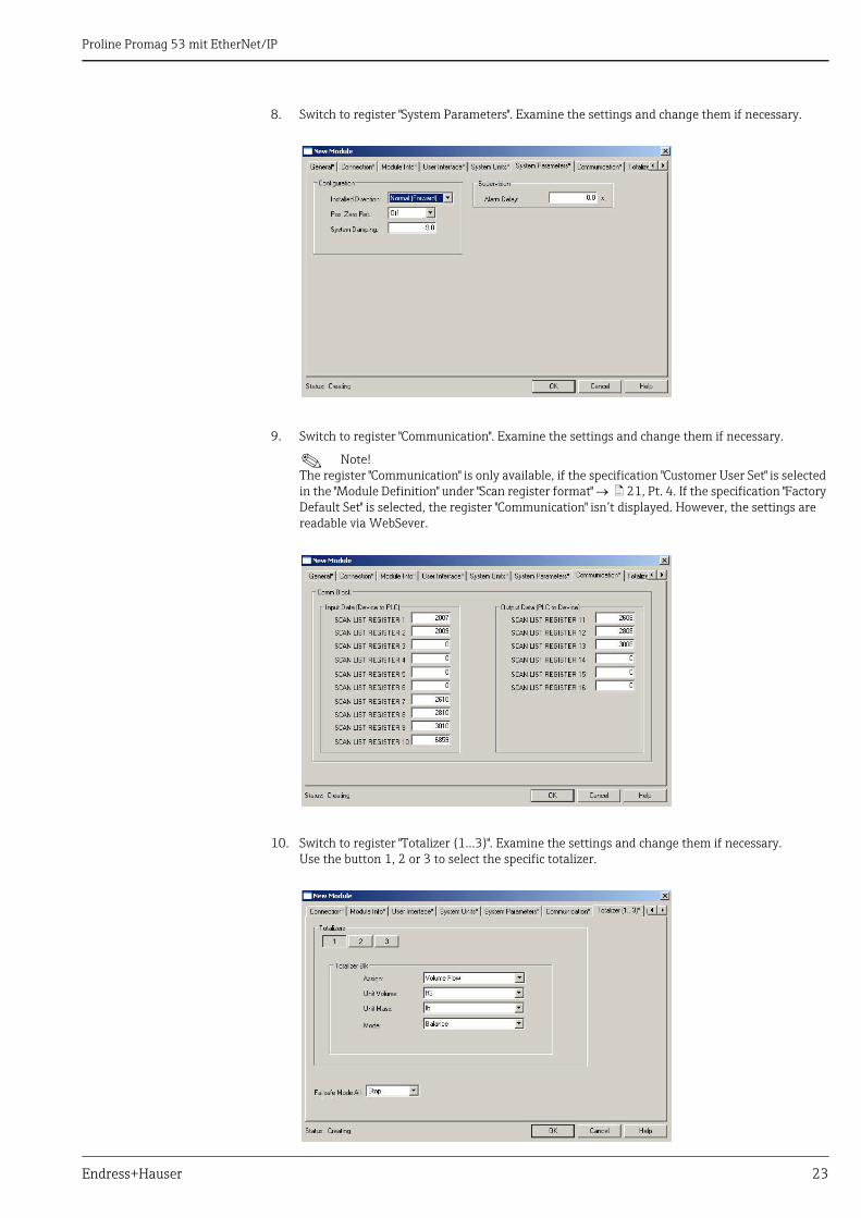
8. Switch to register "System Parameters". Examine the settings and change them if necessary.
9. Switch to register "Communication". Examine the settings and change them if necessary.
! Note! The register "Communication" is only available, if the specification "Customer User Set" is selected in the "Module Definition" under "Scan register format" ä 21, Pt. 4. If the specification "Factory Default Set" is selected, the register "Communication" isn’t displayed. However, the settings are readable via WebSever.
10. Switch to register "Totalizer (1...3)". Examine the settings and change them if necessary. Use the button 1, 2 or 3 to select the specific totalizer.
Proline Promag 53 mit EtherNet/IP
24 Endress+Hauser
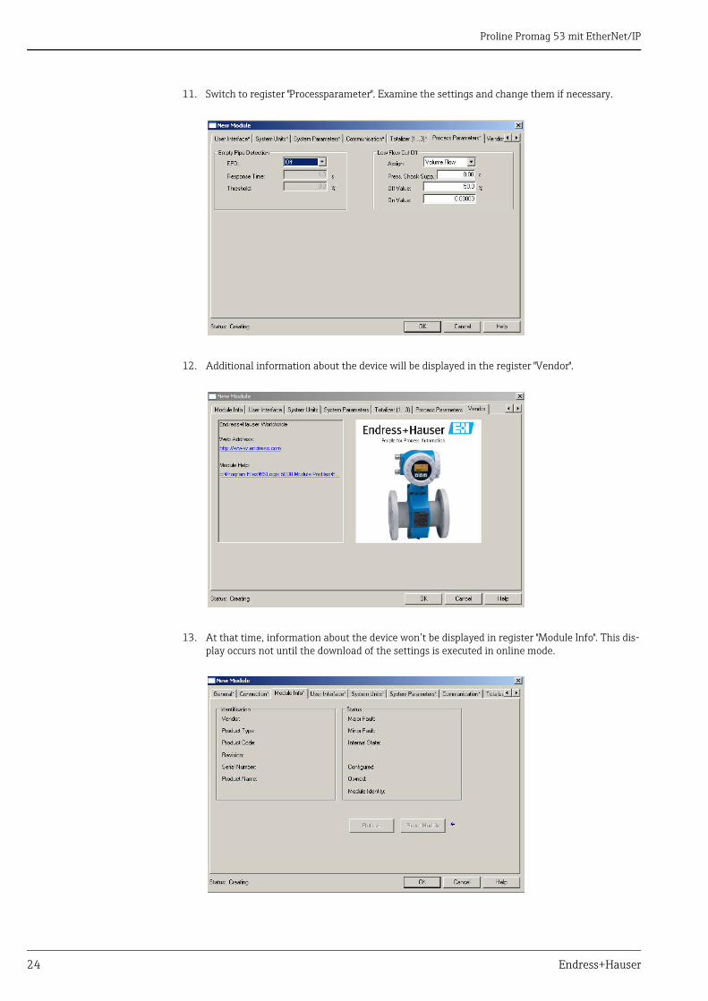
11. Switch to register "Processparameter". Examine the settings and change them if necessary.
12. Additional information about the device will be displayed in the register "Vendor".
13. At that time, information about the device won’t be displayed in register "Module Info". This dis-play occurs not until the download of the settings is executed in online mode.
Proline Promag 53 mit EtherNet/IP
Endress+Hauser 25
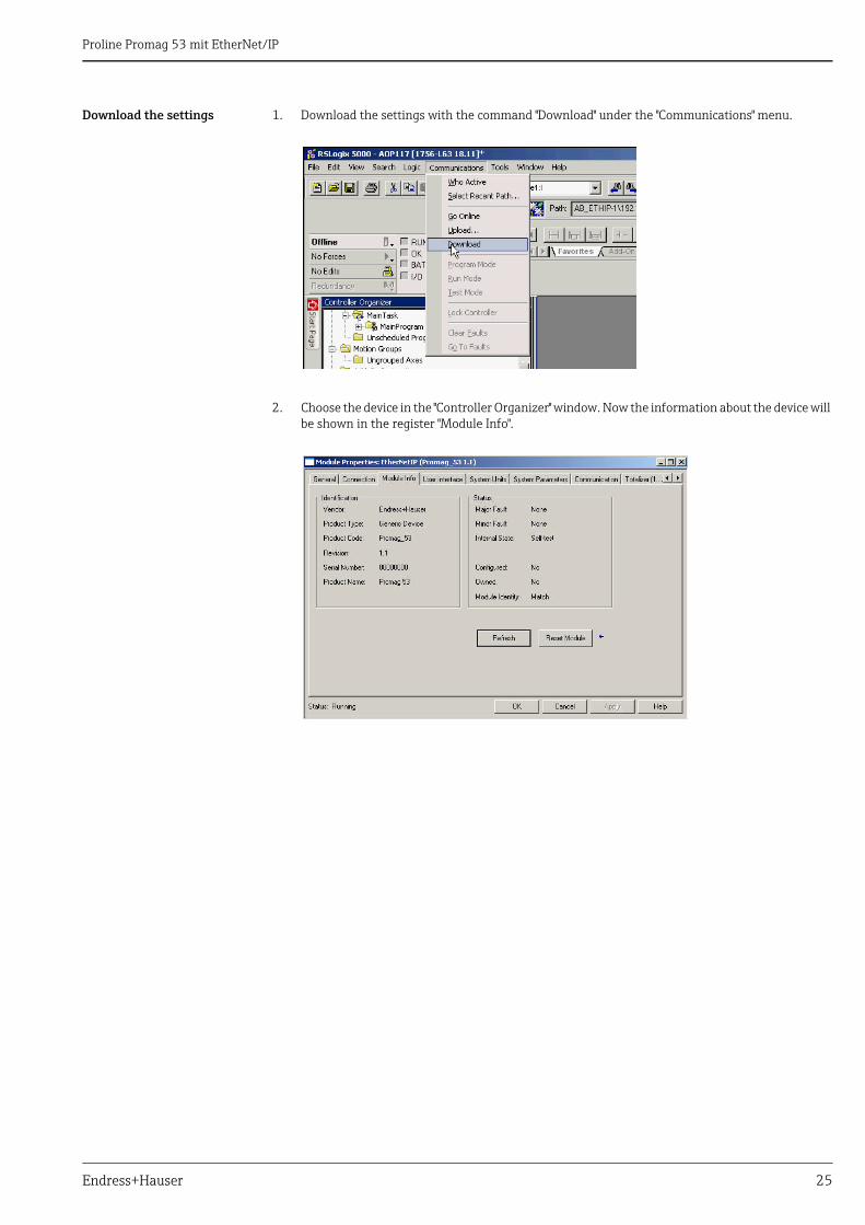
Download the settings 1. Download the settings with the command "Download" under the "Communications" menu.
2. Choose the device in the "Controller Organizer" window. Now the information about the device will be shown in the register "Module Info".
Proline Promag 53 mit EtherNet/IP
26 Endress+Hauser
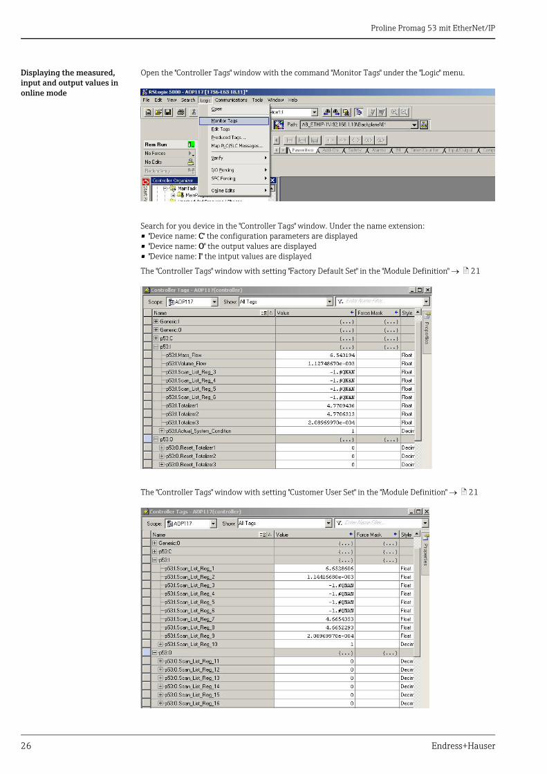
Displaying the measured, input and output values in online mode
Open the "Controller Tags" window with the command "Monitor Tags" under the "Logic" menu.
Search for you device in the "Controller Tags" window. Under the name extension:• "Device name: C" the configuration parameters are displayed• "Device name: O" the output values are displayed• "Device name: I" the intput values are displayed
The "Controller Tags" window with setting "Factory Default Set" in the "Module Definition" ä 21
The "Controller Tags" window with setting "Customer User Set" in the "Module Definition" ä 21

Proline Promag 53 mit EtherNet/IP
Endress+Hauser 27

www.addresses.endress.com