PROJECT XL FOR LANDFILL BIOREACTOR SYSTEMS KING … · FINAL PROJECT AGREEMENT FOR LANDFILL...
102
Transcript of PROJECT XL FOR LANDFILL BIOREACTOR SYSTEMS KING … · FINAL PROJECT AGREEMENT FOR LANDFILL...

DRAFT VERSION – DO NOT CITE OR QUOTE GeoSyntec Consultants
ME0169/FPA6.DOC 1 00.09.20
PROJECT XLFINAL PROJECT AGREEMENT
FOR
LANDFILL BIOREACTOR SYSTEMS
KING GEORGE COUNTY LANDFILL ANDRECYCLING CENTER
ANDMAPLEWOOD RECYCLING AND WASTE
DISPOSAL FACILITY
OPERATED BY
USA WASTE of VIRGINIA, INC.

DRAFT VERSION – DO NOT CITE OR QUOTE GeoSyntec Consultants
ME0169/FPA6.DOC 2 00.09.20
TABLE OF CONTENTS1. INTRODUCTION TO THE AGREEMENT 7
1.1 Description of the Project and its Purpose 71.2 Description of the Facility and Facility Operations/Community/Geographic Area
81.3 Purpose of the Agreement 91.4 List of the Parties that will Sign the Agreement 91.5 List of the Project Contacts 9
2. DETAILED DESCRIPTION OF THE PROJECT 12
2.1 Summary of the Project 122.1.1 Overview 122.1.2 Process Description - Maplewood Landfill Bioreactor 122.1.3 Process Description - King George County Landfill Bioreactor 12
2.2 Specific Project Elements 142.2.1 Maplewood Landfill Bioreactor System 14
2.2.1.1 Overview 142.2.1.2 Bioreactor System Layout and Design 14
2.2.1.3 Liquid Application System Construction 172.2.1.4 Monitoring 182.2.1.5 Data Analysis and Reporting 20
2.2.2 King George County Landfill Bioreactor System 212.2.2.1 Overview 21
2.2.2.2 Bioreactor System Layout and Design 222.2.2.3 Bioreactor Liquids Application System Construction 252.2.2.4 Monitoring 262.2.2.5 Data Analysis and Reporting 28
3. PROJECT XL CRITERIA 29
3.1 Superior Environmental Performance 29

DRAFT VERSION – DO NOT CITE OR QUOTE GeoSyntec Consultants
ME0169/FPA6.DOC 3 00.09.20
3.1.1 Tier 1: Is the Project Equivalent? 293.1.1.1 Overview 29
3.1.1.2 Potential Impact to Groundwater 303.1.1.3 Potential Impact to Surface Water 303.1.1.4 Potential Impact to Air 31
3.1.2 Tier 2: Superior Environmental Performance 313.1.2.1 Overview 313.1.2.2 Potential Impact to Groundwater 323.1.2.3 Potential Impact to Surface Water 333.1.2.4 Potential Impact to Air 35
3.1.3 How Environmental Performance will be Measured 37
3.2 Other Potential Benefits 38
3.3 Stakeholder Involvement 413.3.1 General Information 413.3.2 First Contact and Subsequent Meetings 423.3.3 County Endorsement 433.3.4 State Public Particpation Requirements 433.3.5 Expert Technical Reviewers and Commenters 443.3.7 Repository Information 453.3.8 Stakeholder Meetings and FOIA 453.3.9 Nationwide Solicitation 453.3.10 Stakeholders Shaping the Process 46
3.4 Innovation and Pollution Prevention 46
3.5 Transferability 47
3.6 Feasibility 47
3.7 Evaluation, Monitoring and Accountability 473.7.1 Accountability 473.7.2 Tracking, Reporting, and Evaluation 483.7.3 Failure to Meet Expected Performance Levels 48
3.8 Shifting Risk of Burden 48
DRAFT VERSION – DO NOT CITE OR QUOTE GeoSyntec Consultants
ME0169/FPA6.DOC 4 00.09.20
4. DESCRIPTION OF THE REQUESTED FLEXIBILITY AND IMPLEMENTINGMECHANISMS 49 4.1 Requested Flexibility 49 4.2 Legal Implementing Mechanisms 50 4.3. Compliance and Enforcement History 52
5. DISCUSSION OF INTENTIONS AND COMMITMENTS FOR IMPLEMENTINGTHE PROJECT 54
5.1 Intentions and Commitments 54 5.2 Waste Management’s Intentions and Commitments 54 5.3 Project XL Performance Targets 55 5.4 Proposed Schedule and Milestones 55 5.5 Periodic Review by Parties to the Agreement 56 5.6 Duration 56
6. LEGAL BASIS FOR THE PROJECT 57
6.1 Authority to Enter Into the Agreement 57 6.2 Legal Effect of the Agreement 57 6.3 Other Laws or Regulations that May Apply 58 6.4 Retention of Rights to Other Legal Remedies 58
7. UNAVOIDABLE DELAY DURING PROJECT IMPLEMENTATION 59
8. AMENDMENTS OR MODIFICATIONS TO THE AGREEMENT 60
9. TRANSFER OF PROJECT BENEFITS AND REPONSIBILITIES TO A NEWOWNER 60
10. PROCESS FOR RESOLVING DISPUTES 62
11. WITHDRAWL FROM OR TERMINATION OF THE AGREEMENT63
11.1 Expectations 63
DRAFT VERSION – DO NOT CITE OR QUOTE GeoSyntec Consultants
ME0169/FPA6.DOC 5 00.09.20
11.2 Procedures 63
12. COMPLIANCE AFTER THE PROJECT IS OVER 66
12.1 Introduction 66 12.2 Orderly Return to Compliance with otherwise Applicable Regulations if the
Project Term is Completed 66 12.3 Orderly Return to Compliance with Otherwise Applicable Regulations inthe Event of Early Withdrawl or Termination 66
13. SIGNATORIES AND EFFECTIVE DATE 68
14. REFERENCES 69
TABLESTable 1 Project XL Criteria: Evaluation SummaryTable 2 Summary of Field Scale Leachate Recirculation and Bioreactor ProjectsTable 3 Summary of Benefits for Landfill BioreactorsTable 4 Leachate Quality Improvement Illustration: Central Solid Waste ManagementCenter, Kent County, DelawareTable 5 Design Goals for Bioreactor LandfillsTable 6 Methods for Measuring Envrionmental Performance of Landfill BioreactorProgramTable 7 Preliminary Outline for Project XL Semi Annual Report
FIGURESFigure 1 Project Location MapFigure 2 Cell Base Liner System IllustrationsFigure 3 process Flow Diagram � BioreactorFigure 4 Typical Example: Improvement in Leachate QualityFigure 5 Typical Example: Cumulative Gas GenerationFigure 5 Preliminary Project Schedule

DRAFT VERSION – DO NOT CITE OR QUOTE GeoSyntec Consultants
ME0169/FPA6.DOC 6 00.09.20

DRAFT VERSION – DO NOT CITE OR QUOTE GeoSyntec Consultants
ME0169/FPA6.DOC 7 00.09.20
1. INTRODUCTION TO THE AGREEMENT
1.1. Description of the Project and Its Purpose
This document contains the details of the Final Project Agreement (FPA) betweenUSA Waste of Virginia, Inc., and King George Landfills, Inc., wholly ownedsubsidiaries of Waste Management, Inc. (WM) and the United States EnvironmentalProtection Agency (USEPA) for implementing different bioreactor operations(involving the addition and/or recirculation of bulk liquids, including landfill leachate),at the Maplewood Recycling and Waste Disposal Facility in Amelia County, Virginiaand King George County Landfill and Recycling Center in King George County,Virginia. This document also contains details of the project and the expected benefitsof the project. The general locations of the two facilities are shown on Figure 1. WM’sintent to pursue this project was initially communicated to Ms. Elizabeth Termini of theUSEPA in a letter from the Virginia Department of Environmental Quality (VADEQ)dated 15 February 2000. As part of the project WM is requesting that USEPA grantregulatory relief from certain requirements of the Resource Conservation and RecoveryAct (RCRA) that restrict application of bulk liquids in municipal solid waste landfillsconstructed with particular liner designs, as presented in Title 40 of the Code of FederalRegulations (40 CFR) Section 258.28.
Under this project, bioreactor programs would be implemented at the MaplewoodRecycling and Waste Disposal Facility (Maplewood Landfill) and the King GeorgeCounty Landfill and Recycling Facility (King George County Landfill). The purposesof implementing the bioreactor programs would be to increase the rate ofbiodegradation in the landfills and to facilitate the management of leachate and otherliquid wastes. The primary goal of the project would be to evaluate the relativeimprovement in landfill performance between the two different bioreactors proposed. Itis expected that operation of these landfills, as described in this proposal, would resultin several environmental and cost-saving benefits. It is also anticipated that theinformation obtained will provide the USEPA and the waste disposal industry with dataconcerning the use of bioreactor techniques at municipal solid waste (MSW) landfillsites throughout the United States.
In the remainder of this section, a description of the facilities is presented, contactsfor the project are identified, and the organization of this Final Project Agreement(FPA) is described. In general, this FPA follows the organization provided in the

DRAFT VERSION – DO NOT CITE OR QUOTE GeoSyntec Consultants
ME0169/FPA6.DOC 8 00.09.20
document entitled, “Project XL: Best Practices for Proposal Development” [USEPA,1999] as well as published guidelines for FPA’s. The information on Table 1 identifiesthe location where the specific requirements of the XL Program documents areaddressed in this application.
1.2. Description of the Facility and Facility Operations/Community/Geographic Area
The Maplewood Landfill is located in Amelia County, Virginia, approximately30 miles southwest of Richmond, Virginia. The landfill liner area will cover a total areaof about 404 acres upon completion. Construction of the first phases started in 1992.Construction of the most recent phase was completed in 1997. The King George CountyLandfill is located in King George County, Virginia, approximately 50 miles north-northeast of Richmond, Virginia. The landfill liner area will cover about 290 acres uponcompletion. The first phase of liner system construction began in 1996. Construction ofadditional liner system area has been performed every year since 1996.
Both the Maplewood Landfill and the King George County Landfill wereconstructed having geomembrane composite double-liner systems, with primaryleachate collection and leak detection (secondary collection) layers. The liner systemsfor the two landfills are illustrated on Figure 2. Because these landfills were constructedhaving composite double-liner systems, they provide a high level of protection to theenvironment against potential impacts caused by leakage of leachate. While the linerdesigns do not meet the specified liner design requirements under RCRA (40 C.F.R. §258.40(a)(2) and (b)) which a landfill presently is required to have in place forleachate/gas condensate recirculation (40C.F.R. § 258.28(a)(2)); the liners do meet orexceed the performance requirements for municipal solid waste landfills and have beenshown to be equivalent to the specified liner requirements. For this reason, the projectsponsors believe that these landfills are excellent candidates for the bioreactor programsthat are proposed in this application. The proposed project has been discussed withpotential stakholders, including the USEPA, VADEQ, WM, and the host counties, aswell as the participants identified in Section 3.3. Letters of support for the project fromthe Amelia County and King George County Boards of Supervisors are attached inAppendix A.
DRAFT VERSION – DO NOT CITE OR QUOTE GeoSyntec Consultants
ME0169/FPA6.DOC 9 00.09.20
1.3. Purpose of the Agreement
This FPA is a joint statement of the plans, intentions, and commitments of theUSEPA, the Commonwealth of Virginia, and WM to carry out this project to beapproved for implementation at the Maplewood and King George County Landfills.
The FPA does not create legal rights or obligations and is not an enforceablecontract or a regulatory action such as a permit or a rule. This applies to both thesubstantive and the procedural provisions of this Agreement. While the parties to theAgreement fully intend to follow these procedures, they are not legally obligated to doso. For more detail, please refer to Section 6 (i.e., Legal Basis for the Project).
Federal and State flexibility and enforceable commitments described in thisAgreement will be implemented and become effective through one or more legalimplementing mechanisms, such as a site specific rule or permit amendment issued bythe Commonwealth of Virginia.
All parties to this Agreement will strive for a high level of cooperation,communication, and coordination to assure successful, effective, and efficientimplementation of the Agreement and the Project.
1.4. List of the Parties that Will Sign the Agreement
The Parties to this Final Project XL Agreement are the USEPA, WM, and theVADEQ.
1.5. List of the Project Contacts
The parties involved in the development and preparation of this proposal areidentified below.
State Regulatory Liaison: Mr. E. Paul FarrellEnvironmental Engineer ConsultantVirginia Department of Environmental Quality

DRAFT VERSION – DO NOT CITE OR QUOTE GeoSyntec Consultants
ME0169/FPA6.DOC 10 00.09.20
629 East Main StreetPost Office Box 10009Richmond, Virginia 23219
Project Manager: Mr. James W. Stenborg, P.E.Regional EngineerWaste Management, Inc.King George County Landfill10376 Bullock DriveKing George, Virginia 22485(540) 775-3123
Maplewood Landfill Manager: Mr. Lee WilsonDistrict ManagerMaplewood Recycling Waste Disposal Facility20221 Maplewood RoadJetersville, Virginia 23083
King George County LandfillManager: Mr. Timothy J. Schotsch
District ManagerKing George County Landfill10376 Bullock RoadKing George, Virginia, 22485
Project Engineer: Michael F. Houlihan, P.E.PrincipalGeoSyntec Consultants10015 Old Columbia, Road, Suite A-200Columbia, Maryland 21046
Other Key Waste Management, Inc.Personnel: John A. Baker
Director, Environmental Assessment andTechnology
Greg Cekander, P.E.

DRAFT VERSION – DO NOT CITE OR QUOTE GeoSyntec Consultants
ME0169/FPA6.DOC 11 00.09.20
Vice President of Engineering

DRAFT VERSION – DO NOT CITE OR QUOTE GeoSyntec Consultants
ME0169/FPA6.DOC 12 00.09.20
2. DETAILED DESCRIPTION OF THE PROJECT
2.1 Summary of the Project
2.1.1 Overview
This project involves the operation of two landfills using bioreactor techniques forthe purpose of evaluating the relative benefits of variable liquid application rates in acontrolled manner. The viability and usefulness of these methods is supported byseveral other applications of bioreactor techniques throughout the United States. Asummary of some of these projects is presented in Table 2 and the benefits of thesetechnologies are summarized in Table 3. As part of the project, WM would be grantedflexibility from the RCRA regulatory requirement that restricts application of bulkliquids in municipal solid waste landfills as specified in 40 CFR 258.28(a). In the past,the design goal of a “traditional” landfill was to minimize the quantity of waterintroduced into the landfill, thus minimizing leachate generation. The disadvantage tothis approach is that the lack of liquid causes the biodegradation process to occur veryslowly, thus leaving waste in a relatively undecomposed state for a long period. In thiscase, the liner system is potentially exposed to leachate for a relatively long period oftime, and waste continues to be a potential source of groundwater contaminationthroughout the post-closure period.
Under the XL program, WM will operate the Maplewood Landfill and the KingGeorge County Landfill using bioreactor techniques. At the Maplewood landfill theproject would involve addition of liquids (primarily leachate – for further informationsee section 2.2.1.2) The King George bioreactor will involve addition of leachategenerated at this facility plus other liquids, such as non-hazardous liquid waste orstormwater (for further information see section 2.2.2.2.) A conceptual process diagramfor a landfill bioreactor is presented on Figure 3. The Maplewood and King GeorgeCounty Landfills are located in the same geographic area and receive similar wastestreams. Operating these landfills using two different liquid application rates will allowthe relative performance and cost-saving benefits of the two bioreactor approaches to becompared. The waste received at these landfills is primarily municipal solid wastehaving a small percentage of non-biodegradable products (e.g., construction debris). Inthe absence of Project XL, these landfills would continue to operate under currentlypermitted procedures, which do not include the use of bioreactor technologies (such asliquid application).
DRAFT VERSION – DO NOT CITE OR QUOTE GeoSyntec Consultants
ME0169/FPA6.DOC 13 00.09.20
2.1.2 Process Description – Maplewood Landfill Bioreactor
The landfill bioreactor program that would be implemented at the MaplewoodLandfill involves application of leachate from the landfill and small quantities of otherliquids (e.g., truck, tire waste water, wastewater treatment plant sludges, or stormwater)to the waste. The liquids will be applied over an approximate ten acre area at or near thesurface of the landfill as it will exist in September, 2000. The primary purposes ofrecirculating leachate in this manner is to treat the leachate and to increase the rate ofbiological degradation of waste in a portion of the landfill where liquids are applied.The potential benefits of the bioreactor are presented in Table 3. Treatment of leachateoccurs within the waste when the microbes that naturally exist in the landfill consumeportions of the leachate and waste material. Several studies (including some describedin Table 2) have shown that leachate quality improves over time when leachate isrecirculated on a regular basis. As an example, Table 4 and Figure 4 show leachatequality improving over a period of about seven years at test cells operated by theDelaware Solid Waste Authority’s Central Solid Waste Management Center (CSWMC).Recirculation of leachate can also result in accelerated generation of landfill gas; anexample of accelerated landfill gas generation for the two test cells at CSWMC ispresented on Figure 5. Further, at bioreactor landfills, substantial settlement of thewaste typically can occur during the operating life of the landfill, thus stabilizing thewaste mass and reducing the need for long-term maintenance during the post-closurecare period. This settlement can significantly increase the usable waste disposalcapacity compared to the facility’s original design capacity. Most importantly,bioreactor processes reduce the time needed to achieve a stable waste mass afterclosure. Finally, because the waste mass is more stable, it has more potential end-uses.
2.1.3 Process Description – King George County Landfill Bioreactor
The bioreactor program that will be implemented at the King George County Landfillinvolves applying a quantity of liquid that is about twice that applied at the MaplewoodLandfill. In this landfill bioreactor, conditions will be established that are intended tosignificantly increase the rate of degradation of waste during the operating life of thelandfill to achieve the benefits identified in Table 3. Although the process ofrecirculating leachate provides much of the moisture needed to maximize biologicaldegradation of waste, studies have shown that the quantity of liquid needed to maximizebiodegradation is much greater than the quantity of leachate generated at most landfills.

DRAFT VERSION – DO NOT CITE OR QUOTE GeoSyntec Consultants
ME0169/FPA6.DOC 14 00.09.20
At the King George County Landfill, sources of liquid other than leachate will be usedto supply the additional quantity of liquid needed. These sources may includestormwater, wastewater treatment sludges, or other biota-rich liquid wastes. For thisproject, a controlled amount of leachate, stormwater, and non-hazardous liquid wasteswill be added to the bioreactor test area, as discussed in Section 2.2.2.
2.2 Specific Project Elements
2.2.1 Maplewood Landfill Bioreactor System
2.2.1.1 Overview
In this section, the proposed bioreactor system for the Maplewood Landfill is described.In general, the system is designed to distribute leachate throughout the approximate 10-acre test area as uniformly as possible and to maintain the moisture content of waste at alevel high enough to increase biodegradation. The total footprint is about 48 acres as ofMay 2000. The detailed design of the system is presented in the design report[GeoSyntec, 2000a]. In this section, a brief summary of the design is presented toillustrate the features of the proposed project. The information presented in this sectionis also referenced in Section 3 (i.e., Project XL Criteria) to describe the manner inwhich the proposed program complies with the Project requirements of superiorenvironmental performance. First, in Section 2.2.1.2, the bioreactor system layout anddesign is described. In Section 2.2.1.3, the typical methods for construction of thesystem are described. Finally, in Sections 2.2.1.4 and 2.2.1.5, proposed methods formonitoring and data analysis/reporting are described.
2.2.1.2 Bioreactor System Layout and Design
The proposed study area will be in the landfill’s “Phase Development Areas”Phases 1, 2, 3, 4, and 11. In Phases 1 and 2, liquid will be applied in trenches;excavated beneath the surface of the landfill. The area in Phases 1 and 2 where liquidswill be applied covers an area of about 10 acres. Phases 3, 4, and 11 will be used ascontrol cells where no liquid will be applied; only rainwater that naturally falls andpercolates beneath the landfill surface will enter the waste in these phases. The goals ofthe design for the system will be the following:

DRAFT VERSION – DO NOT CITE OR QUOTE GeoSyntec Consultants
ME0169/FPA6.DOC 15 00.09.20
• recirculate all of the leachate generated at the facility (i.e., up to about4,000,000 gallons per year);
• uniformly distribute leachate throughout the waste mass in the test (i.e.,liquid application) area;
• minimize the potential for the occurrence of seeps by placing distributionstructures at least 50 feet from the crests of outward slopes;
• evaluate the relative effectiveness of different horizontal trench designs foruniformly distributing leachate throughout the waste mass;
• identify several leachate delivery options to simplify operations;
• provide monitoring features within the horizontal trenches so that liquidhead and distribution rate within the trenches can be measured anddocumented; and
• manage landfill gas at all times, including during and following liquidapplication events, to ensure a full compliance with applicable air qualitypermit requirements, and rules and regulations including 40 CFR part 60subpart WWW, (the MSW Landfills NSPS). An active landfill gas collectionand control system is currently in operation at the site. The landfill gascollection and control system components will be enhanced if there is apotential to exceed the applicable air quality permit requirements, and rulesand regulations.
• Minimize uncontrolled releases of landfill gas emissions
The manner in which these goals are addressed in this application are summarizedon Table 5. The design of the Maplewood bioreactor system is based on analyticalmethods developed by Maier, et. al., [1998.] In general, the design was developedbased on the following considerations.
• Leachate Application Quantity and Rate. As described above, the goal forthe Maplewood Landfill is to recirculate as much leachate as is generated atthe facility. Based on facility records, the facility generated approximately

DRAFT VERSION – DO NOT CITE OR QUOTE GeoSyntec Consultants
ME0169/FPA6.DOC 16 00.09.20
3,000,000 gallons of leachate in 1999, which was a relatively dry year.Under this XL project, between 3,000,000 and 4,000,000 gallons of liquidwould be applied per year. The liquid application rate would be 10,960gallons per day, based on an application rate of 4,000,000 gallons per year.A portion of the liquid added could consist of liquids other than leachate, ifthe leachate quantity is relatively low; such “other liquids” could includenon-hazardous liquids such as waste water treatment plant sludges,stormwater or truck washwater.
• Head on Liner. The impact of the proposed liquid application activities onthe depth of liquid (or thickness of “head”), on the liner system wasevaluated using the HELP model. First, the hydrologic evaluation wasperformed assuming that no liquid is applied; then, the evaluation wasperformed for the liquid application condition under the conservativeassumption that 4,000,000 gallons per year is recirculated. The calculatedthickness of head on the liner system is less than the regulatory maximum of12 in.
• Application Capacity of System. The “application capacity” of the system isthe amount of liquid that can be expected to flow by gravity from all of thetrenches. For the Maplewood Landfill, this quantity has been estimatedusing the methodology described by Maier [1998]. This method involvesestimating the moisture content of the waste (typically 15 to 25 percentwithout liquid application), the hydraulic properties of the waste, themoisture retention capacity (field capacity) of the waste (typically 40percent), and the head of liquid on the trench. Using this information, theflowrate of liquid out of one trench into the waste is calculated; the totalapplication capacity equals the combined flowrate of six trenches. As shownin [GeoSyntec, 2000a], the total flowrate capacity of the group of trenches iscalculated to be about 110,000 gallons per day, which is much greater thanthe proposed average rate of 10,960 gallons per day application rate.
• Leachate Storage Capacity of On-Site Structures. It is important that the on-site leachate storage structures have enough capacity to store leachate that isneeded for later application to the trenches. Liquid will be collected andstored for application when conditions are appropriate (i.e., it is not raining).The storage capacity of the leachate tanks at the Maplewood Landfill is

DRAFT VERSION – DO NOT CITE OR QUOTE GeoSyntec Consultants
ME0169/FPA6.DOC 17 00.09.20
approximately 500,000 gallons, which is the average amount of leachategenerated over a period of about two months. During operation of thebioreactor system, leachate storage structures will be used to temporarilystore leachate at times when it is not or cannot be recirculated. As aminimum, the tanks will need to store the quantity of leachate generatedover a period of several days; this is much less time than the approximatelytwo months of storage capacity at the site. Therefore, the facility hasadequate leachate storage capacity for operation of the bioreactor system[GeoSyntec, 2000a]. As a contingency, during times when leachategeneration exceeds the rate of recirculation in and storage capacity, leachatecan be hauled off-site.
• Landfill Gas Control System. A gas collection and control is particularlynecessary at bioreactor landfills; this is because the gas generation rate in abioreactor landfill is greater than without a bioreactor, due to the acceleratedbiodegradation of the waste. To be at least as protective of human healthand the environment as the new source performance standards for municipalsolid waste landfill (i.e., 40 CRF, part 60, subpart WWW) (the MSWLandfills NSPS), WM will continue to provide Subpart WWW-compliantlandfill gas collection and monitoring, during and following the applicationof liquids. If odor problems or air quality problems occur, then the systemwill be expanded as needed (e.g., using additional extraction wells ortrenches or by placing less permeable cover over affected areas). The systemperformance will be documented through routine monitoring of the landfillgas for the presence of methane and other constituents.
2.2.1.3 Liquid Application System Construction
The liquid application system will be constructed using typical trench constructionmethods and other methods developed during the implementation of the program. Theconstruction methods are described in detail in the design report [GeoSyntec, 2000a].The goals of the construction are as follows:
• provide commonly used methods that can be implemented by landfillpersonnel or earthwork contractors during normal operations;
DRAFT VERSION – DO NOT CITE OR QUOTE GeoSyntec Consultants
ME0169/FPA6.DOC 18 00.09.20
• use materials of construction that are readily available, inexpensive, andresistant to degradation by the pressures and chemical constituents present inthe landfill;
• minimize the occurrence of odors or other nuisances during construction ofthe liquids application system.
• Minimize landfill gas emissions by maximizing collection and controlthrough early installation and operation of a comprehensive collection andcontrol system in the bioreactor cell during the construction of the liquidapplication system and throughout the life of the project.
• manage landfill gas at all times, including during and following liquidapplication events, to ensure full compliance with applicable air qualitypermit requirements, and rules and regulations including 40 CFF, part 60,subpart WWW) (the MSW Landfills NSPS). An active landfill gascollection and control system, is currently in operation at the site. Thelandfill gas collection and control system components will be enhanced ifthere is a potential to exceed the applicable air quality permit requirements,and rules and regulations.
2.2.1.4 Monitoring
To verify that the goals of the program and the enforceable component of theFinal Project Agreement are met, the leachate recirculation system will be monitored.The specific goals of the monitoring program will be to:
• measure the leachate quality in phase development areas with and withoutliquid addition over time;
• measure the total quantity of leachate collected in phases with and withoutliquid application and the quantity of leachate or other liquids applied in thetest areas;
• monitor the rate that leachate can be applied to the trenches without causingseeps or other potential operational problems;

DRAFT VERSION – DO NOT CITE OR QUOTE GeoSyntec Consultants
ME0169/FPA6.DOC 19 00.09.20
• monitor the ground surface of the entire site, including the liquid applicationarea, for the presence of landfill gasses (i.e. methane, NMOCs, etc.,) toensure that permit and regulatory limits are not exceeded, and evaluate theneed for additional landfill gas collection components (i.e., wells and headerpipe) during liquid application events to improve the effectiveness of thelandfill gas collection system. (see section 3.1.2.4 Potential EnvironmentalImpact to Air)
• measure the settlement of the waste over the entire landfill area, includingthe liquid application area; this will include semi-annual or more frequenttopographic surveys.
Contingency Plan in the Event of a Failure of the Primary Liner SystemThe primary liner system is underlain by a secondary liner and leachate collection
system. A sump is located at the low point of this system and the sump is monitored forpresence of liquid monthly. Liquid is collected and discharged regularly, and samplesare collected to evaluate the source of the liquids. If the test results from the sampledliquid indicate that there is a leak in the primary liner system, then the need for a largerpump will be evaluated and the liquid level in the primary system will be evaluated andmonitored to minimize the liquid depth above the primary liner and maintain less than12 in. of head. The liner leakage rate will be evaluated and the leachate injection ratemay be reduced, if necessary, to control the rate of the leakage.
Contingency Plan in the Event of a Landfill FireThe proposed study will involve only the anaerobic decomposition of wastes. Thepotential for landfill fires to occur during anaerobic decomposition is much less than thepotential from bioreactors using aerobic decomposition. Nonetheless, the potential for alandfill fire will be evaluated based on monitoring of the gas extraction wells. Becausethe test area is located where the waste is on the order of 50 feet or more in thickness,the primary cause for a fire would likely be from applying excessively high vacuum tothe extraction wells. The test area is not accessible to the atmosphere except at thelandfill surface.
The gas extraction wells will be monitored for parameters such as methane andoxygen concentration and gas temperature at the well head as required by SubpartWWW. This monitoring will be done on a monthly or more frequent basis. If 1)themethane concentration at a well head decreases, 2) oxygen concentration increases, or

DRAFT VERSION – DO NOT CITE OR QUOTE GeoSyntec Consultants
ME0169/FPA6.DOC 20 00.09.20
3) if wellhead temperature increases significantly, this will be the first indication ofuncontrolled waste composting or a potential fire. If any of these monitoring parameterschanges significantly, and a potential fire is suspected, the control valve at theextraction well where the change is observed will be closed. The monitoring of theextraction well will continue for two weeks after the valve is closed. During this time,consideration will also be given to turning off extraction wells located near the wellwhere changes were observed. If the readings at the extraction well have returned tonormal, the valve will be reopened, and extraction will recommence.
If there is no increase in the methane or decrease in the oxygen concentration, or ifthe temperature continues to be significantly higher than historical readings at wellswhere a potential fire is suspected, a decision will be made as to whether to inject wateror leachate should be put into the well to reestablish anaerobic conditions. Water,carbon dioxide, or leachate will be added to the well, if necessary. The proposed studywill involve only the anaerobic approach to the landfill bioreactor. The potential forlandfill fires to occur during anaerobic decomposition is much less than the potentialfrom bioreactors using aerobic decomposition. The potential for a landfill fire will beevaluated based on monitoring of the gas extraction wells. Because the test area islocated where the waste thickness is on the order of 50 feet or more in thickness, theprimary cause for a fire would likely be from applying excessively high vacuum to theextraction wells. The test area is not accessible to the atmosphere except at the landfillsurface.
The methods that will be used to monitor these parameters are described onTable 6. The monitoring parameters and frequency of monitoring are set forth in Table6A. To organize the monitoring data, forms will be generated for use by operationspersonnel to collect and track this information. The surface test for methaneconcentration, which is used to determine collection efficiency and surface integrity,will be conducted according to the MSW Landfill NSPS surface monitoringrequirements set forth in 40 CFR section 60.755(c).
2.2.1.5 Data Analysis and Reporting
The data collected during monitoring events described in Section 2.2.1.4 will beanalyzed for the following trends:

DRAFT VERSION – DO NOT CITE OR QUOTE GeoSyntec Consultants
ME0169/FPA6.DOC 21 00.09.20
• changes in leachate quality on an annual basis;
• relationship between total quantity of leachate generated and liquid appliedin the phases of the landfill;
• range of liquid application rates or qualities to various trenches and potentialproblems arising from certain application rates;
• compliance with the requirements of the Air Quality Permit for the site,including monitoring the ground surface for the occurrence of methane;
• relative performance of the trenches and evaluate an appropriate trenchspacing that is needed to uniformly distribute leachate throughout the wastemass;
• occurrence of seeps and whether they are attributable to operation of theliquid application system; and
• quantity of settlement of landfill surface settlement is areas with and withoutliquid injection.
2.2.2 King George County Landfill Bioreactor System
2.2.2.1 Overview
In this section, the proposed landfill bioreactor system for the King George CountyLandfill is described below. In general, the system will be designed to distribute liquidsas uniformly as possible throughout the test area of the waste mass, and to establishmoisture contents within the test area at a level high enough to significantly increasebiodegradation. The detailed design of the system is presented in King George designreport [GeoSyntec, 2000b]. In this section, a brief summary of the design is presentedto illustrate the features of the proposed project. The information presented in thissection is used in Section 3 (i.e., Project XL Criteria) to describe the manner in whichthe proposed program complies with the Project XL requirements of superiorenvironmental performance. First, the landfill bioreactor system layout and design isdescribed. Then, in Section 2.2.2.3, the typical methods for construction of the system

DRAFT VERSION – DO NOT CITE OR QUOTE GeoSyntec Consultants
ME0169/FPA6.DOC 22 00.09.20
are described. Finally, in Sections 2.2.2.4 and 2.2.2.5, proposed methods formonitoring and data analysis/reporting are described.
2.2.2.2 Bioreactor System Layout and Design
A conceptual process flow diagram for operation of the bioreactor is presented onFigure 3. The overall study area will be established within the MSW Cells 2, 3, and 4of the King George County Landfill. Liquid will be applied in Cell 3; Cells 2 and 4 willbe the control cells in which no liquids will be applied. The overall study area, (i.e.,Cells 2, 3, and 4) covers about 59 acres; the area in Cell 3 where the bioreactor programwill be implemented covers an area of about 10 acres. Cell 1 is currently underconstruction (July 2000) and will be a future control area. The goals of the design forthe bioreactor will be the following:
• recirculate all of the leachate generated at the facility (i.e., up to about4,000,000 gallons per year plus additional liquid so that the total liquidapplication rate is about 8,000,000 gallons per year);
• uniformly distribute leachate throughout the waste mass in the test area (i.e.,liquid application);
• minimize the potential for the occurrence of seeps by placing distributionstructures at least 50 feet from the crests of slopes;
• evaluate the relative effectiveness of liquids in promoting biodegradation bymonitoring surface settlement by cell areas and noting which types of liquidshave been applied in those areas;
• identify several leachate delivery options to simplify operations;
• provide monitoring features within the liquid application structures so thatleachate head and distribution rate within the trenches can be monitoredeffectively; and
• manage landfill gas during liquid application events at all times, includingduring and following liquid application events, to ensure full compliancewith applicable air quality permits requirements, and rules and regulations
DRAFT VERSION – DO NOT CITE OR QUOTE GeoSyntec Consultants
ME0169/FPA6.DOC 23 00.09.20
including 40 CFR part 60 subpart WWW (the MSW Landfills NSPS). Asshown in the design report [Geosyntec 2000a] based on the age of its wastes,the provisions of 40 CFR Subpart WWW and other air quality regulationsrequire that the King George Landfill have installed and are operating anactive landfill gas collection system prior to the commencement of liquidaddition, and to conduct subpart WWW-compliant landfill gas collection andmonitoring, beginning no later than the first application of liquids. If odorproblems or air quality problems occur, then the system will be adjusted orexpanded as needed (e.g. using additional extraction wells or trenches or byplacing less permeable cover over affected areas.) The system performancewill be documented through routine monitoring of the landfill gas for thepresence of methane and other constituents.
The manner in which these goals are addressed are summarized on Table 3. Thedesign of the system will be based on analytical methods developed by Maier, et. al.[1998] as described in Section 4 of the design report [GeoSyntec, 2000b]. In generalthe design was based on the following primary considerations.
• Liquid Application Quantity and Rate. As described above, the goal for theKing George County Landfill is to recirculate as much leachate as isgenerated at the facility and to apply additional liquid to make the totalamount of liquid applied equal to between 7,000,000 and 8,000,000 gallonsper year. Based on facility records for the past three years, the facilitygenerates approximately 3,500,000 gallons of leachate per year. Based onestimates of stormwater runoff quantities and the storage capacity of thestormwater management ponds at the site, approximately 8,000,000 gallonsor more of stormwater can be made available for application to the landfillwaste. The liquid application rate would be, on average, about 22,000gallons per day based on an estimated application rate of 8,000,000 gallonsper year.
• Head on Liner. The impact of the proposed liquid application activities onthe head of liquid on the liner system was evaluated using the HELP model.First, the hydrologic evaluation was performed assuming that no leachate isrecirculated; then, the evaluation was performed for the leachaterecirculation condition under the conservative assumption that 3,500,000gallons/year of leachate is recirculated. The analysis is shown in Appendix A

DRAFT VERSION – DO NOT CITE OR QUOTE GeoSyntec Consultants
ME0169/FPA6.DOC 24 00.09.20
to the design report [GeoSyntec, 2000b]. As shown in the Design Report[GeoSyntec 2000b], the resulting head on the liner system is predicted to be10 in., which is less than the regulatory maximum thickness of 12 in.
• Application Capacity of System. The “application capacity” of the system isthe amount of liquid that can be expected to flow by gravity from all of thetrenches. For the King George County Landfill, this quantity has beenestimated using the methodology described by Maier [1998]. This methodinvolves estimating the moisture content of the waste (typically 15 to 25percent without liquid application), the hydraulic properties of the waste, themoisture retention capacity (field capacity) of the waste (typically 40percent), and the head of liquid on the trench. Using this information, theflowrate of liquid out of one trench into the waste is calculated; the totalapplication capacity equals the combined flowrate of all trenches. As shownin the design report [GeoSyntec, 2000b], the total flowrate capacity of thegroup of trenches is calculated to be about 110,000 gallons per day, which ismuch greater than the proposed 22,000 gallons per day maximumapplication rate.
• Leachate Storage Capacity of On-Site Structures. It is important that the on-site leachate storage structures have enough capacity to store leachate that isneeded for future application to the trenches. Liquid will be collected andstored for application when conditions are appropriate (i.e., it is not raining).The storage capacity of the leachate tanks at the King George CountyLandfill and Recycling Center is approximately 500,000 gallons, which isthe average amount of leachate generated over a period of about two months.During operation of the bioreactor system, leachate storage structures will beused to temporarily store leachate at times when it is not or cannot berecirculated. As a minimum, the tanks will need to store the quantity ofleachate operated over a period of several days; this is much less time thanthe approximately two months of storage capacity at the site. Therefore, thefacility has adequate leachate storage capacity for operation of the bioreactorsystem as designed in the design report [GeoSyntec, 2000b].
• Landfill Gas Control System. A gas collection and control is particularlynecessary at bioreactor landfills. The reason for this is that the gasgeneration rate in a bioreactor landfill is greater than without a bioreactor
DRAFT VERSION – DO NOT CITE OR QUOTE GeoSyntec Consultants
ME0169/FPA6.DOC 25 00.09.20
because of the accelerated biodegradation of the waste. To be at least asprotective of human health and the environment as the new sourceperformance standards for municipal solid waste landfills (i.e., 40 CRF, part60, subpart WWW) (the MSW Landfills NSPS), WM will provide SubpartWWW-compliant landfill gas collection and monitoring, during andfollowing the application of liquids. If odor problems or air qualityproblems occur, then the system will be expanded as needed (e.g., usingadditional extraction wells or trenches or by placing less permeable coverover affected areas). The system performance will be documented throughroutine monitoring of the landfill gas for the presence of methane and otherconstituents
2.2.2.3 Bioreactor Liquids Application System Construction
The liquid application system will be constructed using typical trench constructionmethods. The construction methods are described in detail in Section 5 of the designreport. The goals of the construction methods presented in the design report are:
• provide commonly used methods that can be implemented by landfillpersonnel or earthwork contractors during normal operations;
• use materials of construction that are readily available, inexpensive, andresistant to the degradation by the pressures and chemical constituentspresent in the landfill; and
• control odors or other nuisances during construction of the liquidsapplication system.
• Minimize landfill gas emissions by maximizing collection and controlthrough early comprehensive collection and control practices in thebioreactor cell throughout the life of the project.

DRAFT VERSION – DO NOT CITE OR QUOTE GeoSyntec Consultants
ME0169/FPA6.DOC 26 00.09.20
2.2.2.4 Monitoring
To verify that the goals of the program and the enforceable component of the FinalProject Agreement are met, the leachate recirculation system will be monitored. Thespecific goals of the monitoring program will be to:
• measure leachate quality generated in areas with and without liquid additionover time;
• measure the total quantity of leachate collected in areas with and withoutliquid application and the quantity of leachate or other liquids applied in thetest areas;
• monitor the rate that leachate can be applied to the trenches without causingseeps or other potential operational problems;
• monitor the ground surface of the entire site, including the liquid applicationarea, for the presence of landfill gasses (i.e. methane, NMOCs, etc.,) inexcess of permit limits, and evaluate the need for additional landfill gascollection components (i.e., wells and header pipe) during and followingliquid application events to improve the effectiveness of the landfill gascollection system; (See further discussion in section 3.1.2.4, PotentialEnvironmental Impact to Air.)
• measure the settlement of the waste over the entire landfill area, includingthe liquid application area, this will include semi annual topographicsurveys.
Contingency Plan in the Event of Failure of the Liner SystemThe primary liner system is underlain by a secondary liner and leachate collection
system. A sump is located at the low point of this system and the sump is monitored forpresence of liquid monthly. Liquid is collected and discharged regularly, and samplesare collected to evaluate the source of the liquids. If the test results from the sampledliquid indicates that there is a leak in the primary liner system, then the need for a largerpump will be evaluated and the liquid level in the primary system will be evaluated andmonitored to minimize the liquid depth above the primary liner and maintain less than12" of head. The liner leakage rate will be evaluated and the leachate injection rate maybe reduced, if necessary, to control the rate of the leakage.

DRAFT VERSION – DO NOT CITE OR QUOTE GeoSyntec Consultants
ME0169/FPA6.DOC 27 00.09.20
Contingency Plan in the Event of the a Landfill FireThe proposed study will involve only the anaerobic approach to the landfill
bioreactor. The potential for landfill fires to occur during anaerobic decomposition ismuch less than the potential from bioreactors using aerobic decomposition. Thepotential for a landfill fire will be evaluated based on monitoring of the gas extractionwells. Because the test area is located where the waste is on the order of 50 feet or morein thickness, the primary cause for a fire would likely be from applying excessivelyhigh vacuum to the extraction wells. The test area is not accessible to the atmosphereexcept at the landfill surface.
The gas extraction wells will be monitored for parameters such as methane andoxygen concentration and gas temperature at the well head. This monitoring will bedone on a monthly or more frequent basis. If the methane concentration at the wellhead decreases, oxygen concentration increases or if wellhead temperature increasesignificantly, this will be the first indication of a potential fire. If any of thesemonitoring parameters changes significantly, and a potential fire is suspected, thecontrol at the extraction well where the change is observed will be closed. Themonitoring of the extraction well will continue for two weeks after the valve is closed.During this time, consideration will also be given to turning off extraction wells locatednear the well where changes were observed. If the readings at the extraction well havereturned to normal, the valve will be reopened, and extraction will recommence.
If there is no increase in the methane or decrease in the oxygen concentration, or ifthe temperature continues to significantly higher than historical readings, a decision willbe made as to whether water or leachate should be put into the well to reestablishanaerobic conditions. Water, carbon dioxide, or leachate will be added to the well ifnecessary.
The methods that will be used to monitor these parameters are described in Table 6,and the parameters monitored are included in Table 6A. To simplify the monitoring ofthese parameters, forms will be generated for use by operations personnel in collectingand tracking this information. The surface test for methane concentration, which is usedto determine collection efficiency and surface integrity, will be conducted according tothe MSW Landfill NSPS surface monitoring requirements set forth in 40 CFR section60.755(c).
DRAFT VERSION – DO NOT CITE OR QUOTE GeoSyntec Consultants
ME0169/FPA6.DOC 28 00.09.20
2.2.2.5 Data Analysis and Reporting
The data collected during monitoring events described in Section 2.2.2.4 will beanalyzed for the following trends:
• changes in leachate quality on an annual basis;
• relationship between total quantity of leachate generated and liquid appliedin the phases of the landfill;
• range of liquid application rates or qualities to various trenches and potentialproblems arising from certain application rates;
• early compliance with the requirements of the Air Quality Permit for thesite, including monitoring the ground surface for the occurrence of methane
• relative performance of the trenches and evaluate an appropriate trenchspacing that is needed to uniformly distribute leachate throughout the wastemass;
• occurrence of seeps and whether they are attributable to operation of theliquid application system; and
• quantity of settlement of landfill surface settlement is areas with and withoutliquid injection.
The manner in which these data will be summarized and reported is described inSection 3.1.3.
DRAFT VERSION – DO NOT CITE OR QUOTE GeoSyntec Consultants
ME0169/FPA6.DOC 29 00.09.20
3. PROJECT XL CRITERIA
3.1. Superior Environmental Performance
3.1.1 Tier 1: Is the Project Equivalent?
3.1.1.1 Overview
The existing information on this project indicates that the environmentalperformance of the proposed bioreactor operations at the two sites will be at least asgood, and likely better, than the performance would be expected in the absence of theproject. While the addition of liquids will necessarily increase the amount of leachatepassing through the waste over that which would be expected without liquids addition,the leachate will be fully controlled by maintaining less than 12 in. of head over theliner; moreover, this leachate will be re-circulated, rather than requiring off-sitetreatment and disposal. As described in Section 1.2, both the Maplewood and KingGeorge County Landfills were constructed with composite double-liner systems, whichare highly efficient at preventing leakage of leachate from landfills. Whileimplementation of the project is expected to result in an increase in the generation rateof landfill gas, including methane and nonmethane organic compounds, this gas will becollected and controlled through the use of an active gas collection and control systemand flares at both sites. The parties recognize that the increased production of landfillgas may result in an increase in NOx emissions from the flares. NOx emissions will not,however, exceed the limits specified in WM’s air quality permits. Moreover, WM iscommitted to exploring alternative uses for the collected gas, other than flaring.
These factors, discussed in detail below, show that the project taken as a wholewill result in environmental impacts that will not be greater, and in fact will likely beless, than those that would be expected in the absence of the project
Environmental media that could be impacted include groundwater, surface water,and air. Therefore, the Tier 1 evaluation presented in this section is focused onequivalent potential impacts to these three media, and is presented here for both theKing George and Maplewood Landfills.

DRAFT VERSION – DO NOT CITE OR QUOTE GeoSyntec Consultants
ME0169/FPA6.DOC 30 00.09.20
3.1.1.2 Potential Impact to Groundwater
For an environmental impact to occur to groundwater, leachate would have tomigrate through the liner system of the landfill, flow vertically through the unsaturatedzone, and then impinge on groundwater. As described in Section 1.2, both theMaplewood and King George County Landfills were constructed having compositedouble-liner systems, which exceed the liner performance standard of Subtitle D. Theseliner systems are highly efficient at preventing leakage of leachate from the landfill.The leachate collection systems of both landfills were designed to limit the thickness ofleachate on the underlying liner to no more than 12 in. as required by subtitle D RCRA,which has been verified by design calculations.
When liquids are applied to the landfill, there is a possibility that an increasedquantity of leachate will reach the leachate collection system. Leachate head levels onthe liner may also increase. However, as presented in Section 4.3 of the design reports[GeoSyntec, 2000a and 2000b] when additional liquids are applied, the thickness ofleachate will not exceed 12 in. In reality, applying liquids to the waste above theleachate collection system will enhance the biodegradation process in the landfills,which cause more water to be consumed by landfill gas generation. This further reducesthe amount of liquid that can reach the liner. For these reasons, the potential impact togroundwater will not exceed the potential environmental impact if the project were notimplemented.
3.1.1.3 Potential Impact to Surface Water at the Landfill
For an impact to occur to surface water, leachate would have to migrate laterallyfrom the landfill surface to an aboveground portion of the landfill sideslope and thenflow downslope to a receiving waterbody. Some seeps are likely to occur at landfillsregardless of how well the landfill is designed and operated. Surface water is collectedand monitored prior to discharge, to estimate the potential environmental impact tosurface water caused by seeps. The surface of the landfill will be visually monitored forpotential seepage areas.
Potential impacts that could be caused by seeps are and will continue to bepromptly mitigated at the Maplewood and King George County Landfills through aprogram of seep detection through visual inspections and of maintenance to quickly

DRAFT VERSION – DO NOT CITE OR QUOTE GeoSyntec Consultants
ME0169/FPA6.DOC 31 00.09.20
repair seeps after they are identified. This program of inspections and maintenance willcontinue to be implemented throughout the XL Project. Further, because of the ongoingproject, site personnel will be particularly advised to be more sensitive to the potentialfor seeps. Therefore, the potential environmental impact of the facility to surface waterunder the XL Project will at least be equal to or less than the potential environmentalimpact of a similar project not performed under XL.
3.1.1.4 Potential Impact to Air
For an impact to occur to air, either landfill gas would have to be released from thelandfill in an uncontrolled manner or increased quantities of oxides of nitrogen wouldneed to be released from the on-site flares or other combustion control devices. For theMaplewood Landfill, active landfill gas control systems have been constructed and arecurrently preventing releases of gas in excess of regulatory limits. An active gascollection and control system will be installed at the King George County Landfill on orbefore the addition of liquids under this program. The gas collection and controlsystems will be expanded and upgraded, including in the area of liquids addition, ifroutine monitoring shows it to be necessary. Such additional controls will be installed ifnecessary to meet the landfills’ air quality permit criteria and NSPS (40 CFR Part 60Subpart WWW.) Therefore, the potential impact of the facility to air under the projectshould not exceed the potential impact of the landfill in the absence of the XL Project.
The landfill gas will be collected and controlled through the use of internalcombustion engines, flares or other approved combustion devices. Implementation ofthe project will likely result in the increased production of landfill gas, which will resultin an increase in NOx emissions from the flares. NOx emissions will not, however,exceed the limits specified in WM’s air permits. Moreover, WM is commited toexploring alternative uses for the collected gas, other than flaring.
3.1.2 Tier 2: Superior Environmental Performance
3.1.2.1 Overview
The second tier for the evaluation for Superior Environmental Performancerequires that the applicant demonstrate that the proposed project will result in anenvironmental performance that exceeds the levels of equivalence established for Tier

DRAFT VERSION – DO NOT CITE OR QUOTE GeoSyntec Consultants
ME0169/FPA6.DOC 32 00.09.20
1. In the remainder of this section, quantitative and qualitative factors are described todemonstrate that the project represents a level of environmental performance beyondthe standard for equivalence presented in Section 3.1.1.
3.1.2.2 Potential Environmental Impact to Groundwater
The proposed project will provide environmental performance that is superior tothe baseline of potential environmental impacts to groundwater defined in Section3.1.1.2 in several aspects. The five criteria used to evaluate superior performance inprotecting groundwater quality, as identified in Section III.A.2 of the Best PracticesGuidelines in [USEPA, 1999] are identified below, and the manner in which superiorenvironmental performance will be measured is provided in Section 3.1.3.
• Improvements to Tier 1 Benchmarks. The Tier 1 benchmark is based on thequantity of leachate that could be released to groundwater and, as shown inSection 3.1.1.2, the proposed project is equivalent. In fact, because moreliquid is consumed in a bioreactor landfill than a non-bioreactor landfill,leachate quantity at the site will eventually be less under the proposedproject. In addition to leachate quantity, leachate quality is an equallyimportant factor in evaluating the potential for impacts to groundwaterquality. In bioreactor landfills, the quality of leachate over the long term issubstantially better than the quality of leachate at non-bioreactor landfills, asdemonstrated in Sections 2.2 and 2.3 (see Figure 4). Further, theimprovement in quality will occur sooner in the life of the landfill when thereliability of the leachate containment system (i.e., the liner) is at its highestlevel. These factors result in a substantial long-term improvement inenvironmental performance and protection for the proposed project ascompared to a facility operated outside of the project.
• Pollution Prevention or Source Reduction. Bioreactor landfills substantiallyreduce the source of contamination in landfills and, thereby, significantlycontribute to pollution prevention. As described in Section 2, the primaryenvironmental threat to groundwater and surface-water quality in MSWlandfills is organic constituents within the landfilled waste. By acceleratingthe biodegradation of these wastes, the organic constituents that representthe primary environmental threat are degraded, resulting in a reduction in the

DRAFT VERSION – DO NOT CITE OR QUOTE GeoSyntec Consultants
ME0169/FPA6.DOC 33 00.09.20
source of potential contamination and corresponding prevention of potentialpollution.
• Environmental Performance More Protective than the Industry Standard.The Industry Standard for protection of groundwater resources at MSWlandfills in Virginia is characterized by: (i) screening waste that is receivedat the facility to prevent the disposal of wastes that could adversely impactgroundwater quality; (ii) containing leachate within landfills by constructingeffective liner systems; and (iii) minimizing the formation of leachate bypreventing the addition of liquids during the active life of the landfill andconstructing a low-permeability cover after filling is completed to preventthe formation of leachate. The Industry Standard does not include treatingwaste to minimize its long-term potential to impact groundwater quality.Under the proposed project, waste would be treated in place to minimize itspotential for impacting groundwater quality without adversely impacting theother environmental protection features of the facility.
• Improvement in Environmental Conditions that are Priorities toStakeholders. Based on discussions between the applicant, the VADEQ, andthe host communities for the Maplewood Landfill and the King GeorgeCounty Landfill groundwater-related issues that are priorities to stakeholdersinclude (among others) minimizing the long-term threat to groundwaterquality. This project provides a substantial improvement to the performanceof the existing facilities by treating the waste in the landfills and, thereby,minimizing the potential for waste to present a long-term threat togroundwater quality. Routine groundwater monitoring is, and will continueto be, performed to verify containment.
3.1.2.3 Potential Impact to Surface Water
The proposed project will provide environmental performance that is superior inrespect to the baseline of potential impacts to surface water defined in Section 3.1.1.3 inseveral aspects. The five criteria used to evaluate superior performance in protectingsurface-water quality are identified below, and the manner in which superiorenvironmental performance will be measured is described in Section 3.1.3.

DRAFT VERSION – DO NOT CITE OR QUOTE GeoSyntec Consultants
ME0169/FPA6.DOC 34 00.09.20
• Improvements to Tier 1 Benchmarks. The Tier 1 benchmark for surfacewater environmental impacts is minimizing the occurrence of seeps and, asshown in Section 3.1.1.3, the proposed project is equivalent in this regard.In addition, less leachate would be routed from the facility to the publiclyowned treatment works (POTW), where as much as five percent ofpollutants in the leachate (i.e., wastewater) are typically released to surface-water bodies. Reducing the quantity of liquid sent from the facility to thePOTW will correspondingly decrease the pollutant load to streams caused bydischarges of residue from wastewater treatment plants. Further, surfacewater used in the bioreactor would reduce the quantity of stormwater routedoff site, which would reduce off-site erosion and sedimentation impacts. Inthese manners, the project represents an improvement to the Tier 1benchmarks presented in Section 3.1.1.3.
• Pollution Prevention or Source Reduction. By using leachate to treat wastein the landfill, the source of contamination (i.e., the incidental contaminantsthat are present in a landfill) is reduced and pollution is prevented. Thisresults in superior environmental performance for protection of surface-water resources by eliminating the source of seeps and groundwatercontamination, which can result in surface-water contamination in locationswhere groundwater discharges to surface water.
• Environmental Performance More Protective than the Industry Standard.The Industry Standard for surface-water protection is based on the use ofstandard stormwater management practices and mitigation of occasionalseeps. In addition, by applying stormwater to waste, fewer adverse impactsto off-site receiving streams will be expected during the operating life of thelandfill. Therefore, by applying leachate and stormwater, the environmentalperformance of the Maplewood and King George County Landfills willexceed the Industry Standard for surface-water protection.
• Improvement in Environmental Conditions that are Priorities toStakeholders. Based on discussions between the applicant, the VADEQ, andthe host communities for the Maplewood Landfill and the King GeorgeCounty Landfill, surface-water related issues that are priorities tostakeholders include (among others) protecting surface-water resources fromimpacts by leachate. This project addresses this concern by providing

DRAFT VERSION – DO NOT CITE OR QUOTE GeoSyntec Consultants
ME0169/FPA6.DOC 35 00.09.20
monitoring and operational procedures for preventing impact to surface-water resources by seeps.
3.1.2.4 Potential Environmental Impact to Air
The proposed project will provide environmental performance that is superior to theair environmental impact baseline defined in Section 3.1.1.4 in several aspects.
• Improvements to Tier 1 Benchmarks. The Tier 1 benchmark for potentialenvironmental impact to air is to control landfill gas in a manner consistentwith the requirements of state and Federal air quality permits. As describedin Section 3.1.1.4, the proposed project meets this standard by providinglandfill gas collection and control in the bioreactor cell during the operating,closure, and post-closure periods at both landfills. The most current versionof each facility’s Air Quality Permits (including the part WWW NSPSrequirements) will be used as the criteria for determining if the gas collectionand control system needs modfication. Under this project, landfill gas willlikely be generated at an initially higher rate in the area where additionalliquid is inputted as compared to other areas. The bioreactor cell may requireadditional active gas collection system components, such as wells andheader piping in those affected areas. As more gas is produced andcollection structures are added, the collection efficiency will be improved.Therefore, under this project, less gas is likely to be released from thelandfill surface to the atmosphere than if the project were not implemented,particularly in the landfills’ later years.
As discussed earlier, the landfill gas, including in the areas affected by theliquids addition, will be collected and controlled in the bioreactor cell soonafter the start of liquid addition through the use of flares. Implementation ofthe project will likely result in an increase in the rate of landfill gasproduced, and there may be an increase in NOx emissions from the flares.NOx emissions will not, however, exceed the limits specified in WM’sexisting air permits. In addition, the Tier 1 benchmark will be improvedbecause there will be less impacts from leachate hauling trucks. Leachate iscurrently being transported from the landfills via truck to wastewatertreatment plants. These trucks consume fuel, and there are vehicle emissions

DRAFT VERSION – DO NOT CITE OR QUOTE GeoSyntec Consultants
ME0169/FPA6.DOC 36 00.09.20
associated with this fuel consumption. If leachate is discharged (i.e.,recirculated) into the waste, it will either be pumped using closed pipingsystems or hauled, using trucks, to the various discharge points on thelandfill. By using leachate in the bioreactor, fuel consumption and vehicleemissions will be drastically reduced or eliminated as compared to a projectperformed outside of XL where leachate would be hauled off site.Emissions from on-site trucks (if they are used) will be reduced because hauldistances to the treatment facilities are typically more than 50 miles ascompared to on-site hauling distances of about 2 to 3 miles. Thus, asubstantial long-term improvement in environmental performance for theproposed project will be recognized as compared to a facility operatedoutside of an XL project.
• Pollution Prevention or Source Reduction. Fugitive emissions will bereduced because components of the gas collection and control systems willbe instituted earlier than would othersie be the case, particularly with respectto the King George Landfill. Additionally, at both landfills the accelerateddecomposition of waste will accordingly less of the time in which the wastecan be a source of landfill gas.
• Environmental Performance More Protective than the Industry Standard.The Industry Standard for landfill gas management in Virginia involvesproviding active collection and control of landfill gas at landfills that havethe potential to generate more than 50 Mg per year of NMOCs. Asdescribed in the first item above, the proposed project will exceed thisstandard because more landfill gas would be generated and collected in ashorter period of time under the XL Program than outside the XL Program.The waste mass will more quickly be exhausted of its potential to generategas, and more quickly approach a time when emissions are less the 50 Mgper year. Therefore, the environmental performance of the project will bemore protective than the industry standard.
Early gas collection and control is necessary at bioreactor landfills becausethe site in essence is rapidly “aging” the waste so that it “behaves” as if it ismuch older. The result of this rapid “aging” is more complete biodegradationof the waste resulting in the generation of a larger quantity of landfill gas ata more rapid rate (sooner after waste placement in the landfill.) To be at least

DRAFT VERSION – DO NOT CITE OR QUOTE GeoSyntec Consultants
ME0169/FPA6.DOC 37 00.09.20
as protective of human health and the environment as the new sourceperformance standards for municipal solid waste landfill (i.e., 40 CRF, part60, subpart WWW)(the MSW Landfills NSPS), the following will beprovided at both sites: (i) monitoring as required in the NSPS rules for MSWlandfills; (ii) beginning monitoring sooner than the rule requires, since wasteat bioreactor landfills generates more gas sooner after waste placement; and(iii) continuing the specified monitoring for the duration of the project.
• Improvement in Environmental Conditions that are Priorities toStakeholders. Based on discussions between the applicant, the VADEQ, andthe host communities for the Maplewood Landfill and the King GeorgeCounty Landfill, air-related issues that are priorities to stakeholders include(among others) preventing odor problems. This project provides a substantialimprovement to the performance of the existing facilities by collectinglandfill gas during the active period of filling. Therefore, even though thelandfills may have higher gas generation rates under the XL Project thanthose sites outside of the XL Project, the proposed project represents animprovement on a key environmental condition of high priority tostakeholders.
3.1.3 How Environmental Performance Will Be Measured
Environmental performance will be measured throughout the project todemonstrate the environmental benefits described in Sections 3.1.1 and 3.1.2. Inparticular, measurements will be made of eight elements of the project as identified onTable 6 as well as the manner in which they will be measured. Most of the eightelements are dependent on the same variables, including rate of biological activity andavoidance of potential operational problems that could cause an impact to theenvironment. The measurements identified on Table 6 will be used to make adetermination of superior environmental performance compared to non-recirculatingand non-bioreactor landfills as follows.
• Reduced Impacts to Groundwater Quality. If leachate quality improves overa period of several years or if a trend of improving leachate quality is evidentafter the initial operation period, then it will be concluded that improved

DRAFT VERSION – DO NOT CITE OR QUOTE GeoSyntec Consultants
ME0169/FPA6.DOC 38 00.09.20
leachate quality represents a reduced impact to the liner and leachatecollection system and long-term groundwater quality.
• Reduced Impacts to Surface-Water Quality. If no significant increase in theoccurrence of seeps occurs during the project compared to the occurrence ofseeps at non-bioreactor landfills, then it will be concluded that the liquidapplication methods are acceptable and there are no potential adverseimpacts to surface-water quality.
• Reduced Impacts to Air Quality. Potential impacts to air quality will bereduced if: (i) waste degradation rates increase significantly, as determinedby surveys before and after recirculation or bioreactor activities occur; (ii)the landfill gas management system is routinely monitored, maintained, andoperated throughout the period of the project; and (iii) no significant odorsoccur or surface methane emissions are detected during the project. Theimprovements associated with not having to haul leachate will be recognizedimmediately. Environmental performance will be monitored as described inSections 2.2.1.5 and 2.2.2.5, and the results of the monitoring will bepresented semiannually by WM. A preliminary outline of a typical semi-annual report of monitoring is presented on Table 7.
3.2 Other Potential Benefits
The proposed XL Project is expected to result in several additional benefits. Thesebenefits all result from the accelerated biological degradation that occurs atrecirculating and bioreactor landfills. The benefits are identified below, along with anindication of the nature of the benefit.
Decreased Leachate Management Costs
Because leachate quality is better at recirculating and bioreactor landfills than at non-recirculating or non-bioreactor landfills, the total amount of leachate needs to be treatedis reduced because some of the leachate is consumed in the biological reactions in thelandfill. Also, for landfills where leachate is recirculated less costly treatmenttechniques will be used in the long term if leachate eventually has to be taken off site

DRAFT VERSION – DO NOT CITE OR QUOTE GeoSyntec Consultants
ME0169/FPA6.DOC 39 00.09.20
for treatment and disposal. Therefore, recirculating and bioreactor landfills require lesscost to manage leachate than non-recirculating or non-bioreactor landfills.
Increased Waste Disposal Capacity
The increased rate of biodegradation at recirculating and bioreactor landfills resultsin substantial settlement of waste during the landfills active life. In contrast, at non-recirculating or non-bioreactor landfills, most waste settlement occurs during post-closure (after the final cover has been placed over the waste), making it difficult andimpractical to reclaim the disposal capacity gained through settlement. At recirculatingand bioreactor landfills, a significant amount of settlement can occur during the activelife of the landfill, making it possible to reclaim the disposal capacity gained due tosettlement. Also, the waste mass becomes more stable sooner and better suited for end-use during post-closure. A substantial benefit of increased waste disposal capacity isthe ability to delay or avoid siting a new waste disposal facility, a benefit that has alarge quantitative economic benefit and a high qualitative benefit. Further, withadditional disposal capacity, the host communities will receive additional revenue fromfees paid on a “per ton” basis.
Increased Use of Recycled Materials
The materials to be used as the drainage media in the liquid application structurewill typically include coarse aggregate or other suitable recyclable materials such as tireshreds. Tire shreds are commonly generated as a result of the cleanup of old tire pilesin the Commonwealth of Virginia. When a beneficial use of tires such as this isavailable, a portion of the processing cost from the cleanup of tirepiles is paid by theVADEQ because of the beneficial end use. The tire cleanup program is funded by a taxon the purchase of new tires.
Improved Economics of Energy Recovery Project Feasibility
Energy recovery from landfill gas is a project that involves collection of landfillgas and beneficial use such as generating of energy either by direct generation ofelectricity or by burning the gas as an alternative energy source. The economicfeasibility of such energy recovery projects is a function of the reliability of the quantityof landfill gas that can be generated during the life of the project. For example, landfills

DRAFT VERSION – DO NOT CITE OR QUOTE GeoSyntec Consultants
ME0169/FPA6.DOC 40 00.09.20
that generate a relatively small quantity of gas per year may not be candidates for anenergy recovery project due to an insufficient quantity to make the project cost-effective. Even if the total quantity of landfill gas generated over the life of the facilityis very large, certain projects may not be economical if the gas generation rate isrelatively low. Because increased levels of biodegradation cause higher gas generationrates (such as in recirculating and bioreactor landfills) more gas is available in the short-term for energy recovery projects. With the increased rate of landfill gas beinggenerated, energy recovery projects will be more economically feasible.
Earlier Availability for Re-Use of Site
Less settlement occurs during the post-closure period at recirculating and bioreactorlandfills. This is because more of the potential settlement is achieved prior to closure.These landfills represent a reduced potential impact to environmental quality asdescribed above in this application. Thus, there are more potential options for using thesite during and after the post-closure period.
Reduced Settlement and Strain on Final Cover System
There is less potential for damage to the final cover system by settlement because moreof the potential settlement occurs in recirculating and bioreactor landfills before thefinal cover system is constructed. This has a direct impact on the cost of the post-closure operation and maintenance activities. Because the final cover system willexperience less settlement, the long-term containment of the final cover system isimproved.
Decreased Post-Closure Care Costs
Because waste is stabilized more quickly in recirculating and bioreactor landfills,several long-term benefits occur as described in this section, including: (i) shorter timethat leachate will need to be managed and, therefore, shorter period of leachatemanagement system operation and leachate treatment; (ii) shorter duration of landfillgas generation and, therefore, shorter period of landfill gas management systemoperation; reduced settlement during the post-closure period and, therefore, decreasedmaintenance costs for repairing potential cover damage due to settlement; and (iii)decreased potential for groundwater degradation and, therefore, lower potential for theneed for groundwater remediation. These benefits all result in lower post-closure care

DRAFT VERSION – DO NOT CITE OR QUOTE GeoSyntec Consultants
ME0169/FPA6.DOC 41 00.09.20
costs for recirculation or bioreactor landfills as compared to non-recirculating and non-bioreactor landfills. Based on studies performed by Shaw and Knight [2000], theestimated savings in post-closure operation and maintenance costs for bioreactorlandfills is in the range of 40 to 60 percent as compared to non-bioreactor landfills.
Comparison Between Approaches to Bioreactor Technology
A significant technological benefit of this project is that it would allow for a directcomparison between the performance of bioreactor landfills operated with varyingamounts of liquid introduced into the waste mass. This comparison can be made withinthe site itself from areas with and without liquid injection, and between the two sites.As previously described, the Maplewood Landfill would receive up to 4,000,000gallons per year of liquid in a nominal 10-acre area. The King George County Landfillwould receive as much as 8,000,000 gallons per year of liquid in approximately thesame area. Because the landfills are located in the same area of the country, receivesimilar amounts of precipitation, and receive similar waste streams, the relative impactof liquid quantity on waste decomposition can be evaluated by comparing the resultsfrom the two.
3.3 Stakeholder Involvement
3.3.1 General Information
Primary participants include the regulatory community of USEPA and VADEQ,and WM, local community councils and government officials, and interested membersof the public. USEPA and VADEQ have had considerable influence on the details ofthe project proposal and will continue their active involvement during theimplementation phase.
Interested parties have demonstrated some interests in the project, yet do not wishto actively participate in project development and implementation. Interested partieswill usually want be kept informed of project development and progress, and may wishto attend public meetings and contribute their comments in written or verbal form.
Members of the general public will, most likely, not become actively involved inproject development and implementation. Although not actively involved, members will

DRAFT VERSION – DO NOT CITE OR QUOTE GeoSyntec Consultants
ME0169/FPA6.DOC 42 00.09.20
be provided with project information through the local media and central informationrepository. Members of the general public have the opportunity to participate moreactively if they choose to do so.
A Final Project Agreement (FPA) is an agreement between the USEPA and theSponsors stating the purpose and requirements of the project and how the project is tobe implemented and evaluated. It is completed through a cooperative effort between theUSEPA, Sponsors, and the Stakeholders.
A permit amendment amends an existing permit for a landfill. There are specificregulatory and technical requirements that must be met for a successful permitamendment. There are prescriptive public participation requirements. A landfill istypically permitted under 9 VAC 20-80-250 and 9 VAC 20-80-500 of the Virginia SolidWaste Management Regulations (VSWMR) and by the Code of Virginia, §10.1-1400 etseq. However, because the bioreactor projects are not typical at landfills the permits willbe amended under VSWMR, 9 VAC 20-80-480.G which allows for an experimentalpermit for innovative treatment technologies.
3.3.2 First Contact and Subsequent Meetings
• Public Meeting on 1 August 2000 (King George County) and 2 August 2000(Amelia County) to solicit comments from the public on the intent of theSponsors to participate in Project XL.
• Public Meetings the week of 4 September 2000 to discuss the draft FPAwith the citizens.
• Public Meeting and Hearing 16 October 2000 (King George County) and 17October 2000 (Amelia County) to discuss the Draft Permit Amendments forthe landfills.
A kickoff meeting was held on 1 August 2000 for King George County and 2August 2000 for Amelia County. Both meetings were held at 7:00 p.m. A copy of theadvertisements are provided in Appendix VI and include project information, contactinformation, and repository information. The public will have about 10 to 15 days torespond with comments after the public meeting is held. Participants may become
DRAFT VERSION – DO NOT CITE OR QUOTE GeoSyntec Consultants
ME0169/FPA6.DOC 43 00.09.20
actively involved at the time of the meetings in the continuing process or be put on amailing list to receive periodic information. Another public meeting may be held a fewweeks later to solicit additional participants and comments. As part of the VADEQ’spermitting process, a public hearing must be held on each of the draft permitamendments. Details of the public hearing process are provided below. It is anticipatedthat the public hearings for each of the draft permits will most likely occur the week of16 October 2000. At the second meetings, the Draft FPA will be made available forreview and comment. As the FPA is revised and amended, it will be made available atsubsequent meetings and at the local library. The availability of the FPA will beadvertised prior to the public hearings held by the VADEQ.
3.3.3 County Endorsement
The Counties of Amelia and King George endorse the respective projects asevidence by letters of support. These landfills have not had major opposition but, rather,had public support. Conditions of the host agreements provide benefits to the residentsof both counties through revenue and jobs. The respective projects under Project XLwould not affect the host agreements, thus the Counties would continue to receive thesebenefits. Thus, any Stakeholder opposition in these counties is anticipated to beminimal. However, the sponsors will publish an advertisement describing the desiredprojects as discussed above. An additional advertisement will be part of the VADEQ’spublic participation process as outlined below.
3.3.4 State Public Participation Requirements
Before VADEQ issues a permit amendment, it holds a public hearing in the locality tosolicit comments on the draft permit from concerned citizens. The public hearing isadvertised in the local paper. The public hearing is held a minimum of 30 days from thedate of the advertisement. Public comment period begins the day of advertisement andends 15 days after the public hearing is held. Furthermore, the VADEQ has astandardized mailing list of state agencies to whom a draft permit or notice of draftpermit is sent to solicit comments. The VADEQ evaluates the comments and prepares apublic response document. The VADEQ Director then decides within 30 days after theclose of comment period whether or not to issue the permit. Conditions may be imposeddue to additional state requirements or as a result of public comment. In the initial
DRAFT VERSION – DO NOT CITE OR QUOTE GeoSyntec Consultants
ME0169/FPA6.DOC 44 00.09.20
stages of permitting, the applicant notifies all of the adjacent property owners of hisintent to modify or expand the landfill. In this notification, the project is described andcontact information is provided. The citizens can comment on the project at this stage orat any other stage of the permitting process until the permit has been issued.
Since both landfills have a valid permit, the VADEQ intends to amend the permitto allow the bioreactor systems as an experimental process. The major amendmentswould be advertised and open to comment as described above. The details of therespective projects would be outlined in the advertisements along with contactinformation and document viewing locations. It is anticipated this would help identifyadditional Stakeholders.
3.3.5 Expert Technical Reviewers and Commenters
There will be specific experts and technical advisors who will review the FPA andmake appropriate comments on its technical adequacy and regulatory compliance. Someof these Stakeholders have already been contacted by the Sponsors and have agreed, inpart, to review the project. They include faculty members from Virginia PolytechnicInstitute and State University (Virginia Tech) and North Carolina State University.Specific individuals are not named in this report because, depending upon availability,they may change over the course of the review time. Other third-party expert reviewersmay include Waste Policy Institute, EMCON, and Richardsons and Associates. Theywill be contacted and offered the opportunity to review and comment.
3.3.6 Getting the Word Out
The public hearings as required by the VADEQ will be supplemented withadditional Stakeholder meetings, as necessary. A partial mailing list is attached. Themailing list would be updated as necessary to include private citizens and otherinterested parties. Periodically, progress reports and other relevant information will bedistributed. Mail would be sent on a recurring date or as information is made available.If desired, the Sponsors will provide site tours and briefings to better educate theStakeholders. Transcripts and video tape recordings of all public meetings and hearingswill be maintained at the repositories.

DRAFT VERSION – DO NOT CITE OR QUOTE GeoSyntec Consultants
ME0169/FPA6.DOC 45 00.09.20
3.3.7 Repository Information
An official record of the project will be maintained by the Sponsors at 629 EastMain Street, Richmond, VA, 22129 c/o Paul Farrell, (804) 698-4214. A mirror set willbe maintained within each county at the local library. The address for the library inAmelia County is: the James Hamner Memorial Library, 16351 Dunn Street Amelia,Virginia 23002 and the file will be entitled “Amelia County Landfill, Maplewood Site,Project XL”. The address for the library in King George County is: L.F. Smoot LewisMemorial Library, 9533 Kings Highway, King George, Virginia 22485, and the filewill be entitled “King George County Landfill Project XL”.
3.3.8 Stakeholder Meetings and FOIA
Once the Stakeholders have been clearly identified, the Sponsors will periodically meetwith the representative of each group or the entire group to discuss issues of concernand to disseminate information. Other members of the groups may personally voice aconcern or receive progress reports during the planned public meetings. All informationis public domain. Any information that is not currently in the repository may beobtained through a “freedom of information act” (FOIA). To facilitate informationalrequests, all FOIA request will be placed on a fast-track. It must still meet all of thelegal requirements of a FOIA but the information will be provided in a timely manner.The information requested will then be put in the repositories for future reference.
3.3.9 Nationwide Solicitation
To solicit additional Stakeholder involvement, the Sponsors will contactnationwide professional and citizen groups that may have an interest in bioreactortechnology. The Solid Waste Association of North America has monthly publications todisseminate information to its members. Periodically, the Sponsors may attend nationalworkshops or seminars. These meetings would be an ideal forum to present the meritsof the individual projects and to actively recruit Stakeholders.

DRAFT VERSION – DO NOT CITE OR QUOTE GeoSyntec Consultants
ME0169/FPA6.DOC 46 00.09.20
3.3.10 Stakeholders Shaping the Process
The initial meetings will solicit comments and provide information to the public inorder for them to the make an informed opinion of the process. The Stakeholders may,at any time, provide to the Sponsors comments on the Proposal. However, in order tocreate an enforceable document, the comments must be incorporated into the finalpermit required by the VADEQ. During the VADEQ public participation process, theVADEQ responds to the comments through a public response document. Conditionsmay be imposed due to additional VADEQ requirements or as a result of publiccomment. The permit is an enforceable document under the Virginia Solid WasteManagement Act. Public comments shape the final permit.
3.4 Innovation and Pollution Prevention
The proposed project provides a high level of innovation for managing leachateand environmental quality at a MSW landfill. Although not a new technology, leachaterecirculation and other bioreactor technologies are not widely used at MSW landfills inthe United StatesThis may be due in part to a lack of data that demonstrates the benefitsof the technologies and information on how to best apply these technologies. Currentstate and Federal regulations also create some limitations. This XL project is intended toprovide data to further demonstrate the benefits of leachate recirculation and otherbioreactor technology.
In addition to being innovative, leachate recirculation and bioreactor technologiesrepresent a significant advancement in reducing potential pollution from MSW landfills.The key pollution prevention aspects of these technologies are: (i) retention andtreatment of leachate in the landfill, where it is well contained and can be processedutilized and treated in a secure environment; (ii) decreased impacts to air qualitythrough the use of landfill gas collection system through the operating life of the facilityin areas where biodegradation is being promoted; and (iii) increased rate of stabilizationof waste, which results in improved leachate quality in the long term and a smallerpotential for impacts to groundwater quality.

DRAFT VERSION – DO NOT CITE OR QUOTE GeoSyntec Consultants
ME0169/FPA6.DOC 47 00.09.20
3.5 Transferability
WM believes that the type of technology to be tested in this project should beuseful at most operating MSW landfills in the United States. The technology is expectedto yield substantial economic and environmental benefits for nearly all regions of theU.S. Although this project focuses on the effects of liquids additions to MSWLFs in anarea with particular geological features and climate, WM expects this project to produceinformation that is useful throughout the country.
3.6 Feasibility
Leachate recirculation and bioreactor technologies have been used at several otherwaste disposal facilities, as presented on Table 2. Based on the successful applicationsof these technologies and operational experience at other facilities, the proposed projectis feasible.
3.7 Evaluation, Monitoring, and Accountability
3.7.1 Accountability
The two landfills involved in this demonstration project operate under theirrespective Commonwealth of Virginia solid waste and air quality permits. Each permitis an enforceable document that carries civil penalties for major violations. The Directorof the VADEQ has the authority to revoke the permit if necessary. However, there havebeen no Notices of Violation at either site.
The parties intend to implement as enforceable commitments, federal and stateregulatory flexibility, monitoring, record-keeping, and reporting provisions of this FPAthrough a site-specific rule and a Federally Enforceable State Operating Permit(FESOP). The legal mechanisms that would apply to this project include a FESOP forgas collection and monitoring, and a site-specific rule for liquid additions. The VADEQis the regulatory agency that has permitting authority for both landfills. The FESOPwould contain enforceable parameters and requirements with respect to NSPS-compliant gas collection and monitoring prior to liquid additions and/or leachaterecirculation, whichever occurs first. The FESOP would require a public notice andcomment period. In addition, USEPA will be issuing a proposed rule for liquidadditions at both landfills. This rule would also require a public comment period. Either
DRAFT VERSION – DO NOT CITE OR QUOTE GeoSyntec Consultants
ME0169/FPA6.DOC 48 00.09.20
the FESOP or the site-specific rule (as appropriate) would contain the projectmonitoring and reporting requirements listed in sections 2.2.1.4, 2.2.1.5, 2.2.2.4, and2.2.2.5, Table 6 and 6A and would require that WM provide semi-annual reporting ofthe monitoring data to stakeholders and regulators in order to facilitate projectevaluation. USEPA, VADEQ, State, and other appropriate regulatory agencies willassess the project annually based on all information submitted. USEPA will post WM’sproject data on its Project XL webpage semi-annually.
3.7.2 Tracking, Reporting, and Evaluation
Data collection, evaluation, and reporting requirements are identified in Section 2and Table 6 and 6A. In general, for each facility, the data collection and analysisrequirements of the XL Program features will be reported semiannually to the EPA andVADEQ as described in Section 3.7.1 or as otherwise required by the legalimplementing mechanisms. Sections 2.2.1.4 and 2.2.2.4 discuss the monitoringparameters for this project.
3.7.3 Failure to Meet Expected Performance Levels
In the event that the expected levels of performance are not achieved, then thebioreactor programs will be reviewed with the WM and the operation of the facilitieswill be modified to attempt to better achieve expected goals.
3.8 Shifting Risk of Burden
WM does not propose to shift the burden of any of the risks associated withoperating the landfills as a result of this project. In particular, any risk of failure of theproposed leachate recirculation or bioreactor systems will be borne by WM. The risksthat could be shifted include: (i) impacts to media; (ii) impacts to disadvantagedcommunities; and (iii) financial burden of post-closure care or operation. The proposedproject does not represent a shift of risk burden because: (i) the technologies involveddo not transfer pollutants from one environmental media to another; (ii) there are nodisadvantaged communities near the two sites; and (iii) WM will continue to assume thefinancial burden of all operations, and monitoring and post-closure care for thefacilities. In fact, the proposed project results in decreased overall risk associated withwaste management because, in the long term, the accelerated biodegradation provided
DRAFT VERSION – DO NOT CITE OR QUOTE GeoSyntec Consultants
ME0169/FPA6.DOC 49 00.09.20
by the project results in a reduced risk of potential impacts from releases of leachate orlandfill gas to the environment.
4. DESCRIPTION OF THE REQUESTED FLEXIBILITY ANDIMPLEMENTING MECHANISMS
4.1 Requested Flexibility
As part of the proposal, WM is requesting that the USEPA grant regulatoryflexibility from the requirement of the RCRA that restricts application of bulk liquids inMSW landfills, as presented in 40 CFR 258.28(a) as follows.
• It prohibits the placement of liquid wastes other than leachate, gascondensate, and non-septic household waste in any MSW landfill.
• Leachate or gas condensate is allowed provided the landfill unit is designedwith a composite liner and leachate collection system as described in section258.40(a)(2).
• The addition of septic waste is allowed.
Neither landfill has the specified liner therefore reg relief is needed to allowrecirculation of leachate in both landfills. Secondly, the reg prohibits the placement ofliquid waste other than leachate/gas condensate and non septic household waste in anyMSW landfill. Therefore both landfills require regulatory relief in order to add anyother bulk liquids.
As described in Section 2, liquids are needed to enhance the biological degradationof waste in the landfills. Therefore, WM proposes to add liquids to both landfills and toadd certain nonhazardous liquid wastes (e.g., leachate, stormwater, gray water, septicwaste, etc.). The Maplewood Landfill currently has an active landfill gas collectionsystem that is in operation; if odor problems or air quality problems occur, then thesystem will be expanded as needed (e.g., using additional extraction wells or trenches orby placing less permeable cover and affected areas). As part of this project, WM hasagreed to design and construct an active landfill gas collection system at the KingGeorge Landfill prior to the commencement of liquids addition, and to conduct SubpartWWW-compliant landfill gas collection and monitoring. Further, both the Maplewood
DRAFT VERSION – DO NOT CITE OR QUOTE GeoSyntec Consultants
ME0169/FPA6.DOC 50 00.09.20
and King George County Landfills have liner systems that are superior in performanceto the liner system described above.
4.2 Legal Implementing Mechanisms
Federal
To implement this Project, EPA intends to take the following steps:
EPA expects to propose for public comment and promulgate a site-specific ruleamending 40 CFR 258.28 for the Maplewood and King George County Landfills. Thissite-specific rule will describe the project requirements and any other aspects of therulemaking. It is expected that the site-specific rule will provide for Withdrawal orTermination and a Post-Project Compliance Period consistent with Section 7, and willaddress the Transfer procedures included in Section 9. The standards and reportingrequirements set forth in Section 2 and Table 6 and 6A (and any attachments to thisFPA) will be implemented in this site-specific rulemaking and/or the FederallyEnforceable State Permit (as appropriate) will implement the standards and reportingrequiremements set forth in section 2 and Table 6 and 6A.
Specifically, EPA expects to grant flexibility from the RCRA requirements that 1)restrict the recirculation of leachate in a MSWLF unless it has a composite linerdesigned as prescribed in the design standard in 40 CFR 258.40(a)(2), and 2) restrictsthe application of bulk liquids other than the landfill’s leachate (and gas condensate) inMSWLF waste landfills (40 CFR Section 258.28.)
Commonwealth of Virginia
The Commonwealth of Virginia under its relevant authority expects to modify orissue any permits necessary to implement this FPA.
Specifically, in accordance with 9 VAC 20-80-480.G, “The director may issue anexperimental facility permit for any solid waste treatment facility which proposes toutilize an innovative and experimental solid waste treatment technology or process…”,Maplewood and King George County Landfill, will submit permit amendmentapplications to obtain experimental permits for the proposed bioreactor landfill areas.Specific criteria will be developed by the Office of Solid Waste Permitting at VADEQ
DRAFT VERSION – DO NOT CITE OR QUOTE GeoSyntec Consultants
ME0169/FPA6.DOC 51 00.09.20
to guide the design, operation, and construction of bioreactor landfills. The staff in theoffice will review the experimental permit application for different aspects includinglocal certification, design, construction, operation, closure, variance, finance assurance,and public participation.
In the current permits, both facilities hold a variance to the requirements of 9 VAC20-80-250.B.9, which addresses requirements for liner systems; as shown on Figure 2,both landfills were constructed having double-liner system but neither landfill has acomposite liner consisting of a geomembrane underlain by a two-foot thick layer of clayhaving a hydraulic conductivity of 1 x 10⁻⁷ cm/sec, as required by RCRA Subtitle Dand VSWMR. Under the current federal and state regulations, the facilities must filevariance petitions for recirculating leachate within landfills underlain by alternate linersystems. In addition, both facilties must submit an additional variance petition to theVADEQ for introducing bulk liquids into the proposed bioreactor landfill area.
If the permit applications are found to be administratively complete and technicallyacceptable, draft permits will be developed by the VADEQ. The permit issuanceprocedure will follow 9 VAC 20-80-500.E, in which a public notice of the draft permitshall be made and a public hearing shall be held subsequently. The VADEQ directorwill make a final decision to the permit, to deny a permit or to amend the draft permitwithin 30 days of the close of the hearing comment period.
In accordance with 9 VAC 20-80-480.G, an experimental permit shall provide foroperation of the facility for no longer than one calendar year unless renewed asprovided in 9 VAC 20-80-480.G.3 which stipulates that the permit may be renewed nomore than three times with each renewal for a period of not more than one calendar yeareach time it is renewed.
At this point, amendments to stormwater permits are not anticipated for eitherfacility. However, the VADEQ Office of Waste Permitting will work with otherpermitting groups if any amendments on air or stormwater become necessary.
The Commonwealth of Virginia under its relevant authority expects to modify anypermits necessary to implement this FPA.
WM Waste Management will submit an application to the VADEQ requesting thatVADEQ issue a Federally Enforceable State Operating Permit ("FESOP") VADEQ inconsultation with EPA, expects to issue a FESOP which incorporates all of the landfillgas monitoring requirements specified in section 2 and table 6A of this agreement andcontains adequate provisions to ensure that landfill gas is collected and controlled in
DRAFT VERSION – DO NOT CITE OR QUOTE GeoSyntec Consultants
ME0169/FPA6.DOC 52 00.09.20
accordance with the requirements of 40 CFR part 60, subpart WWW - Standards ofPerformance for Municipal Solid Waste Landfills. VADEQ will work with WM toensure that the FESOP is issued in a timely manner.
General
Except as provided in any rule(s), compliance order(s), permit provisions or otherimplementing mechanisms that may be adopted to implement the Project, the parties donot intend that this FPA will modify or otherwise alter the applicability of existing orfuture laws or regulations to the Maplewood or King George County Landfills.
By signing this FPA, USEPA, the Commonwealth of Virginia and its localauthorities acknowledge and agree that they have the respective authorities anddiscretion to enter into this FPA and to implement the provisions of this project, to theextent appropriate.
4.3 Compliance and Enforcement History
VADEQ has the regulatory authorities over Maplewood and King George CountyLandfill. Staff at the VADEQ conduct air, waste, and wastewater inspections at the twofacilities on a regular basis. The compliance and enforcement history of the facilitieshas been reviewed for this particular application.
King George County Landfill
• Waste Inspection. Conducted monthly by the VADEQ’s Northern VirginiaRegional Office. The VADEQ has reviewed the most recent 12 monthlyinspection reports. The overall rating for each inspection is satisfactory. NoNotice of Violation has been issued.
• Air Inspection. In 1990, the USEPA established an Operating PermitProgram under Title V (40 CFR Part 70) of the Federal Clean Air Act(CAA). Title V is an operating permit program, enforced through federaland state rules, requiring compilation of an air emissions inventory,identification of applicable regulations, and certifications of compliance.This facility has submitted a Title V permit application to the VADEQ andthe approval is pending. However, the facility was issued a State OperatingPermit and is inspected annually by the VADEQ’s Fredericksburg Satellite
DRAFT VERSION – DO NOT CITE OR QUOTE GeoSyntec Consultants
ME0169/FPA6.DOC 53 00.09.20
Office.The applicable regulations include New Source PerformanceStandards (NSPS) and State Implementation Plan (SIP). The review on therecent annual inspection reports indicates that the facility is in good standingwith the applicable regulations.
• Stormwater Inspection. The leachate generated in this facility is hauled toand treated in a public owned wastewater treatment facility. The facility isexempt from the requirements of the Virginia Pollutant DischargeElimination System (VPDES) permit for its stormwater run-off control.Stormwater is monitored in accordance with an agreement between WM andKing George County. The run-off stormwater is collected into sedimentationbasins via conveyance channels before being discharged to naturalwaterways. Diversion channels were constructed to minimize stormwaterrun-on.
Maplewood Landfill
• Waste Inspection. The waste inspection is conducted monthly by theVADEQ’s Piedmont Regional Office. The VADEQ has reviewed the mostrecent 12 inspection reports. The overall rating for each inspection issatisfactory. No Notice of Violation has been issued.
• Air Inspection. Same as King George County Landfill, the facility submitteda Title V permit application and the approval is pending. However, thefacility holds a valid new Source Review (NSR) permit and the airinspection is conducted once a year by the VADEQ’s Lynchburg SatelliteOffice. The inspection reports for the past three years have been reviewedby the VADEQ. The results of the three reports indicate that the facility hasbeen in compliance with the applicable regulations which include NSPS andSIP.
• Stormwater Inspection. Currently, leachate generated from this facility iscollected and temporarily stored in the storage tanks on site. The leachate isthen hauled to a treatment facility for further treatment. Direct discharge ofleachate to surface water is prohibited in this facility. The facility has aVPDES permit for its stormwater run-off control. Perimeter diversion andcollection channels are constructed for run-off and run-off storm water

DRAFT VERSION – DO NOT CITE OR QUOTE GeoSyntec Consultants
ME0169/FPA6.DOC 54 00.09.20
control respectively. The run-off stormwater enters to sedimentation basinsbefore being discharged to a surface waterway.
5. DISCUSSION OF INTENTIONS AND COMMITMENTS FOR IMPLEMENTING THE PROJECT
5.1 Intentions and Commitments
WM would like to operate the areas identified in Section 1 as controlled bioreactorlandfills to attain a number of superior environmental and cost savings benefits. WM iscommitted to working with federal, state, and local governments to demonstrate, withregulatory flexibility, how a bioreactor landfill can attain more desirable environmentalresults than a conventional landfill.
5.2Waste Management’s Intentions and Commitments
Enforceable:WM will comply with all applicable environmental requirements duringimplementation of this Project.
WM will establish a record keeping system to ensure compliance, as well as accuratereporting of monitoring data from Section 2 and Tables 6 and 6A.
As discussed in section 4.2 (Legal Implementing Mechanism) WM will submit anapplication to the VDEQ requesting the issuance of a FESOP.
WM intends to provide accurate data for the proposed bioreactor landfill. This datashould enable EPA and the State to develop or modify regulatory requirements foridentified parameters, such as those identified in Table 6 and 6A of this FPA.
Voluntary:
WM is committed to working with federal, state, and local governments to demonstrate,with regulatory flexibility, how a bioreactor landfill can attain more desirableenvironmental results than a conventional landfill.
DRAFT VERSION – DO NOT CITE OR QUOTE GeoSyntec Consultants
ME0169/FPA6.DOC 55 00.09.20
WM intends to continue to provide resources to maintain the schedules set forth in thisFPA.
EPA’s, Commonwealth of Virginia, and other Local Regulatory Agency’sIntentions and Commitments
As discussed in section 4.2 (Legal Implementing Mechanism) EPA intends to proposeand issue a site-specific rule, amending 40 CFR Part 258.28, that applies specifically tothe the two sites.
The State and other local governing regulatory agencies will assist the XL Project Teamin understanding all applicable regulatory and/or permitting requirements for theProject, and evaluate any need for regulatory flexibility openly with the Team.
USEPA and the other regulatory agencies will review and assess annual and periodicreports submitted by Waste Management.
USEPA will review the Project to determine whether it results in superiorenvironmental performance.
The State and other local regulatory agencies will assist USEPA in reviewing theProject to determine whether it results in superior environmental performance.
5.3 Project XL Performance Targets
See Table 6, Methods for Measuring Environmental Performance of LandfillBioreactor program.
5.4 Proposed Schedule and Milestones
This project will be developed and implemented over a time period necessary tocomplete its desired major objectives, beginning from the date that the final legalmechanism becomes effective, unless it is terminated earlier or extended by agreementof all Project Signatories. An expected timeline is shown on Figure 6.
DRAFT VERSION – DO NOT CITE OR QUOTE GeoSyntec Consultants
ME0169/FPA6.DOC 56 00.09.20
5.5 Periodic Review by the Parties to the Agreement
The Parties will hold periodic performance review conferences to assess theirprogress in implementing this Project. Unless they agree otherwise, the date for thoseconferences will be concurrent with annual Stakeholder Meetings. No later than 30 daysfollowing a periodic performance review conference, WM will provide a summary ofthe minutes of that conference to all Direct Stakeholders. Any other comments ofparticipating Stakeholders will be reported toWM.
5.6 Duration
This Agreement will remain in effect for 10 years after signing, unless the Projectends at an earlier date, as provided under Section 8 (Amendments or Modifications),Section 11 (Withdrawal or Termination), or Section 9 (Transfer of Project Benefits andResponsibilities). The implementing mechanism(s) will address withdrawal ortermination conditions and procedures (as described in Section 11). This Project willnot extend past the agreed upon date, and WM will comply with all applicablerequirements following this date (as described in Section 12), unless all parties agree toan amendment to the Project term (as provided in Section 8).

DRAFT VERSION – DO NOT CITE OR QUOTE GeoSyntec Consultants
ME0169/FPA6.DOC 57 00.09.20
6. LEGAL BASIS FOR THE PROJECT
6.1 Authority to Enter Into the Agreement
By signing this Agreement, all signatories acknowledge and agree that they havethe respective authorities, discretion, and resources to enter into this Agreement and toimplement all applicable provisions of this Project, as described in this Agreement.
6.2 Legal Effect of the Agreement
This Agreement states the intentions of the Parties with respect to WM’s XLProject. The Parties have stated their intentions seriously and in good faith, and expectto carry out their stated intentions. This Agreement in itself does not create or modifylegal rights or obligations, is not a contract or a regulatory action, such as a permit or arule, and is not legally binding or enforceable against any Party. Rather, it expresses theplans and intentions of the Parties without making those plans and intentions bindingrequirements. This applies to the provisions of this Agreement that concern proceduralas well as substantive matters. Thus, for example, the Agreement establishesprocedures that the parties intend to follow with respect to dispute resolution andtermination (see Sections 10 and 11). However, while the parties fully intend to adhereto these procedures, they are not legally obligated to do so.
EPA intends to propose for public comment a site specific rule making needed toimplement this Project. Any rules, permit modifications or legal mechanisms thatimplement this Project will be effective and enforceable as provided under applicablelaw.
This Agreement is not a “final agency action” by EPA because it does not create ormodify legal rights or obligations and is not legally enforceable. This Agreement itselfis not subject to judicial review or enforcement. Nothing any Party does or does not dothat deviates from a provision of this Agreement, or that is alleged to deviate from aprovision of this Agreement, can serve as the sole basis for any claim for damages,compensation or other relief against any Party.
DRAFT VERSION – DO NOT CITE OR QUOTE GeoSyntec Consultants
ME0169/FPA6.DOC 58 00.09.20
6.3 Other Laws or Regulations That May Apply
Except as provided in the legal implementing mechanisms for this Project, theparties do not intend that this FPA will modify any other existing or future laws orregulations.
6.4 Retention of Rights to Other Legal Remedies
Except as expressly provided in the legal implementing mechanisms described inSection IV, nothing in this Agreement affects or limits, WM’s, the VADEQ’s, or anyother signatory’s legal rights. These rights include legal, equitable, civil, criminal oradministrative claims or other relief regarding the enforcement of present or futureapplicable federal and state laws, rules, regulations or permits with respect to thefacility.
Although WM does not intend to challenge agency actions implementing theProject (including any rule amendments or adoptions, permit actions, or other action)that are consistent with this Agreement, WM reserves any right it may have to appeal orotherwise challenge any USEPA, Commonwealth of Virginia, or local agency action toimplement the Project. With regard to the legal implementing mechanisms, nothing inthis Agreement is intended to limit WM’s right to administrative or judicial appeal orreview of those legal mechanisms, in accordance with the applicable procedures forsuch review.

DRAFT VERSION – DO NOT CITE OR QUOTE GeoSyntec Consultants
ME0169/FPA6.DOC 59 00.09.20
7. UNAVOIDABLE DELAY DURING PROJECT IMPLEMENTATION
“Unavoidable delay” (for purposes of this Agreement) means any event beyondthe control of any Party that causes delays or prevents the implementation of the Projectdescribed in this Agreement, despite the Parties’ best efforts to put their intentions intoeffect. An unavoidable delay can be caused by, for example, a fire or acts of war.
When any event occurs that may delay or prevent the implementation of thisProject, whether or not it is avoidable, the Party to this Agreement who knows about itwill immediately provide notice to the remaining Parties. Within ten days after thatinitial notice, the Party should confirm the event in writing. The confirming noticeshould include: (i) the reason for the delay; (ii) the anticipated duration; (iii) all actionstaken to prevent or minimize the delay; and (iv) why the delay was consideredunavoidable, accompanied by appropriate documentation.
If the Parties, agree that the delay is unavoidable, then relevant parts of the projectschedule (see Section 5) will be extended to cover the time period lost due to the delay.If they agree, they will also document their agreement in a written amendment to thisAgreement. If the Parties don’t agree, then they will follow the provisions for DisputeResolution outlined below.
This section applies only to provisions of this Agreement that are not implementedby legal implementing mechanisms. Legal mechanisms, such as permit provisions orrules, will be subject to modification or enforcement as provided under applicable law.

DRAFT VERSION – DO NOT CITE OR QUOTE GeoSyntec Consultants
ME0169/FPA6.DOC 60 00.09.20
8. AMENDMENTS OR MODIFICATIONS TO THE AGREEMENT
This Project is an experiment designed to test new approaches to environmentalprotection and there is a degree of uncertainty regarding the environmental benefits andcosts associated with activities to be undertaken in this Project. Therefore, it may beappropriate to amend this Agreement at some point during its duration.
This FPA may be amended by mutual agreement of all parties at any time duringthe duration of the Project. The parties recognize that amendments to this Agreementmay also necessitate modification of legal implementation mechanisms or may requiredevelopment of new implementation mechanisms. If the Agreement is amended, WMand USEPA expect to work together with other regulatory bodies and stakeholders toidentify and pursue any necessary modifications or additions to the implementationmechanisms in accordance with applicable procedures (including public notice andcomment). If the parties agree to make a substantial amendment to this Agreement, thegeneral public will receive notice of the amendment and be given an opportunity toparticipate in the process, as appropriate.
In determining whether to amend the Agreement, the parties will evaluate whetherthe proposed amendment meets Project XL acceptance criteria and any other relevantconsiderations agreed upon by the parties. All parties to the Agreement will meet withinninety (90) days following submission of any amendment proposal (or within a shorteror longer period if all parties agree) to discuss evaluation of the proposed amendment. Ifall parties support the proposed amendment, the parties will (after appropriatestakeholder involvement) amend the agreement.
9. TRANSFER OF PROJECT BENEFITS AND RESPONSIBILITIES TO ANEW OWNER AND/OR OPERATOR
The parties expect that the implementing mechanisms will allow for a transfer ofWM’s benefits and responsibilities under the Project to any future owner and/oroperator upon request of WM and the new owner and/or operator, provided that thefollowing conditions are met:
A. WM will provide written notice of any such proposed transfer to the USEPA,the Commonwealth of Virginia (VADEQ and any other appropriate state agencies) andall applicable local agencies at least 90 days before the effective date of the transfer.
DRAFT VERSION – DO NOT CITE OR QUOTE GeoSyntec Consultants
ME0169/FPA6.DOC 61 00.09.20
The notice is expected to include identification of the proposed new owner and/oroperator, a description of its financial and technical capability to assume the obligationsassociated with the Project, and a statement of the new owner and/or operator’sintention to take over the responsibilities in the XL Project of the existing owner and/oroperator.
B. Within 45 days of receipt of the written notice, the parties expect that USEPA,WM, VADEQ, and all applicable local agencies in consultation with all stakeholders,will determine whether: (i) the new owner and/or operator has demonstrated adequatecapability to meet USEPA’s requirements for carrying out the XL Project; (ii) is willingto take over the responsibilities in the XL Project of the existing owner and/or operator;and (iii) is otherwise an appropriate Project XL partner. Other relevant factors,including the new owner and/or operator’s record of compliance with Federal, state andlocal environmental requirements, may be considered as well. It is expected that theimplementation mechanism will provide that, so long as the demonstration has beenmade to the satisfaction and unreviewable discretion of USEPA, VADEQ, and allapplicable local agencies and upon consideration of other relevant factors, the FPA willbe modified to allow the proposed transferee to assume the rights and obligations ofWM. In the event that the transfer is disapproved by any agency, withdrawal ortermination may be initiated, as provided in Section 11.
It will be necessary to modify the Agreement to reflect the new owner and/oroperator and it may also be necessary for USEPA, VADEQ, and all applicable localagencies to amend appropriate rules, permits, or other implementing mechanisms(subject to applicable public notice and comment) to transfer the legal rights andobligations of WM under this Project to the proposed new owner and/or operator. Therights and obligations of this project remain with WM prior to their final, legal transferto the proposed transferee.
DRAFT VERSION – DO NOT CITE OR QUOTE GeoSyntec Consultants
ME0169/FPA6.DOC 62 00.09.20
10. PROCESS FOR RESOLVING DISPUTES
Any dispute which arises under or with respect to this Agreement will be subject toinformal negotiations between the parties to the Agreement. The period of informalnegotiations will not exceed 20 calendar days from the time the dispute is firstdocumented, unless that period is extended by a written agreement of the parties to thedispute. The dispute will be considered documented when one party sends a writtenNotice of Dispute to the other parties.
If the parties cannot resolve a dispute through informal negotiations, the partiesmay invoke non-binding mediation by describing the dispute with a proposal forresolution in a letter to the Regional Administrator for USEPA Region 3, with a copy toall parties. The Regional Administrator will serve as the non-binding mediator and mayrequest an informal mediation meeting to attempt to resolve the dispute. He or she willthen issue a written opinion that will be non-binding and does not constitute a final WMaction. If this effort is not successful, the parties still have the option to terminate orwithdraw from the Agreement, as set forth in Section 11 below.

DRAFT VERSION – DO NOT CITE OR QUOTE GeoSyntec Consultants
ME0169/FPA6.DOC 63 00.09.20
11. WITHDRAWAL FROM OR TERMINATION OF THE AGREEMENT
11.1 Expectations
Although this Agreement is not legally binding and any party may withdraw fromthe Agreement at any time, it is the desire of the parties that it should remain in effectthrough the expected duration of 10 years, and be implemented as fully as possibleunless one of the conditions below occur:
1. Failure by any party to: (i) comply with the provisions of the enforceableimplementing mechanisms for this Project; or (ii) act in accordance with theprovisions of this Agreement. The assessment of the failure will take itsnature and duration into account.
2. Failure of any party to disclose material facts during development of theAgreement.
3. Failure of the Project to provide superior environmental performanceconsistent with the provisions of this Agreement.
4. Enactment or promulgation of any environmental, health or safety law orregulation after execution of the Agreement, which renders the Projectlegally, technically or economically impracticable.
5. Decision by an agency to reject the transfer of the Project to a new owner oroperator of the facility.
In addition, USEPA and VADEQ do not intend to withdraw from the Agreement ifWM does not act in accordance with this Agreement or its implementation mechanisms,unless the actions constitute a substantial failure to act consistently with intentionsexpressed in this Agreement and its implementing mechanisms. The decision towithdraw will, of course, take the failure’s nature and duration into account.
WM will be given notice and a reasonable opportunity to remedy any “substantialfailure” before WM’s withdrawal. If there is a disagreement between the parties overwhether a “substantial failure” exists, the parties will use the dispute resolutionmechanism identified in Section 10 of this Agreement. WM, the USEPA, and all

DRAFT VERSION – DO NOT CITE OR QUOTE GeoSyntec Consultants
ME0169/FPA6.DOC 64 00.09.20
applicable local agencies retain their discretion to use existing enforcement authorities,including withdrawal or termination of this Project, as appropriate. WM retains anyexisting rights or abilities to defend itself against any enforcement actions, inaccordance with applicable procedures.
11.2 Procedures
The parties agree that the following procedures will be used to withdraw from orterminate the Project before expiration of the Project term. They also agree that theimplementing mechanism(s) will provide for withdrawal or termination consistent withthese procedures.
1. Any party that wants to terminate or withdraw from the Project is expectedto provide written notice to the other parties at least sixty days before thewithdrawal or termination.
2. If requested by any party during the sixty day period noted above, thedispute resolution proceedings described in this Agreement may be initiatedto resolve any dispute relating to the intended withdrawal or termination. If,following any dispute resolution or informal discussion, a party still desiresto withdraw or terminate, that party will provide written notice of finalwithdrawal or termination to the other parties.
3. If any agency withdraws or terminates its participation in the Agreement, theremaining agencies will consult with WM to determine whether theAgreement should be continued in a modified form, consistent withapplicable federal or State law, or whether it should be terminated.
4. The procedures described in this section apply only to the decision towithdraw or terminate participation in this Agreement. Procedures to be usedin modifying or rescinding any legal implementing mechanisms will begoverned by the terms of those legal mechanisms and applicable law. It maybe necessary to invoke the implementing mechanism’s provisions that endauthorization for the Project (called “sunset provisions”) in the event ofwithdrawal or termination.

DRAFT VERSION – DO NOT CITE OR QUOTE GeoSyntec Consultants
ME0169/FPA6.DOC 65 00.09.20
DRAFT VERSION – DO NOT CITE OR QUOTE GeoSyntec Consultants
ME0169/FPA6.DOC 66 00.09.20
12. COMPLIANCE AFTER THE PROJECT IS OVER
12.1 Introduction
The parties intend that there be an orderly return to compliance uponcompletion, withdrawal from, or termination of the Project, as follows:
12.2. Orderly Return to Compliance with Otherwise Applicable Regulations ifthe Project Term is Completed
If, after an evaluation, the Project is terminated because the term has ended, then WMwill return to compliance with all applicable requirements by the end of the Projectterm, unless the Project is amended or modified in accordance with Section 8 of thisAgreement (Amendments or Modifications). WM is expected to anticipate and plan forall activities to return to compliance sufficiently in advance of the end of the Projectterm. WM may request a meeting with the USEPA, and all applicable local agencies todiscuss the timing and nature of any actions that they will be required to take. Theparties should meet within thirty days of receipt of WM’s written request for such adiscussion. At and following such a meeting, the parties should discuss in reasonable,good faith, which of the requirements deferred under this Project will apply aftertermination of the Project.
12.3 Orderly Return to Compliance with Otherwise Applicable Regulations inthe Event of Early Withdrawal or Termination
In the event of a withdrawal or termination not based on the end of the Project termand where WM has made efforts in good faith, the parties to the Agreement willdetermine an interim compliance period to provide sufficient time for WM to return tocompliance with any regulations deferred under the Project. The interim complianceperiod will extend from the date on which WM, the Commonwealth of Virginia, and allapplicable local agencies provides written notice of final withdrawal or termination ofthe Project, in accordance with Section 11 of this Project Agreement. By the end of theinterim compliance period, WM will comply with the applicable deferred standards setforth in 40 CFR Part 258.28. During the interim compliance period, WM, theCommonwealth of Virginia, and any applicable local agency may issue an order,

DRAFT VERSION – DO NOT CITE OR QUOTE GeoSyntec Consultants
ME0169/FPA6.DOC 67 00.09.20
permit, or other legally enforceable mechanism establishing a schedule for WM toreturn to compliance with otherwise applicable regulations as soon as practicable. Thisschedule cannot extend beyond six months from the date of withdrawal or termination.WM intends to be in compliance with all applicable Federal, State, and localrequirements as soon as is practicable, as will be set forth in the new schedule.
DRAFT VERSION – DO NOT CITE OR QUOTE GeoSyntec Consultants
ME0169/FPA6.DOC 68 00.09.20
13. SIGNATORIES AND EFFECTIVE DATE
__________________________________James W. Stenborg, P.E.Waste Management, Inc.
___________________________________Paul FarrellVirginia Department of Environmental Quality
___________________________________Bradley M. CampbellRegional Administrator, Region 3, USEPA

DRAFT VERSION – DO NOT CITE OR QUOTE GeoSyntec Consultants
ME0169/FPA6.DOC 69 00.09.20
14. REFERENCES
Gou, V. and Guzzone, B., “State Survey on Leachate Recirculation and LandfillBioreactors”, Solid Waste Association of North America, 1997.
GeoSyntec Consultants, “Maplewood Bioreactor Plan”, Waste Management, Inc.,Jetersville, VA, May 2000a.
GeoSyntec Consultants, “King George Bioreactor Plan”, Waste Management, Inc.,King George, VA, May 2000b.
Maier, T.B., “Analysis Procedures for Design of Leachate Recirculation Systems”,Proceedings of the 3rd Annual SWANA Landfill Symposium, Palm Beach Gardens,Florida, June, 1998.
Maier, T.B., Steinhauser, E.S., Vasuki, N.C., and Poland, F. G., “Integrated Leachateand Landfill Gas Management”, proceedings of the Fifth International LandfillSymposium, Cagliari, Italy, October, 1995, pp. 53-66.
Maier, T.B., Vasuki, N.C., “Expected Benefits of a Full-Scale Bioreactor Landfill”,proceedings of Wastecon 1996, Portland, Oregon, September, 1996, pp. 179-195.
Reinhart, D.R., and Al-Yousfi, A.B., “The Impact of Leachate Recirculation onMunicipal Solid Waste Landfill Operating Characteristics”, Waste Management andResearch, Vol. 14, August, 1996, pp. 337-346.
Reinhart, D.R., “Full-Scale Experiences with Leachate Recirculating Landfills: CaseStudies”, Waste Management and Research, Volume 14, No. 4, pp. 347-365, August1996.
Schroeder, P.R., McEnroe, B.M., Peyton, R.L., and Sjostrom, J.W., “The HydrologicEvaluation of Landfill Performance (HELP) Model, Vol. III, User’s Guide for Version2.05,” 1988.
Shaw, P.A., and Knight, A.J., “Quantitative Analysis of Potential Savings and Earningsby Implementing a Bioreactor Landfill”, proceedings of WasteTech 2000, Orlando,Florida, March 2000.
DRAFT VERSION – DO NOT CITE OR QUOTE GeoSyntec Consultants
ME0169/FPA6.DOC 70 00.09.20
Vasuki, N.C., Leachate Generation in a Lined Landfill: A Case Study of the CentralSolid Waste Facility at Sandtown, DE,” Purdue University Industrial Waste ConferenceProceedings, 1986.
Vasuki, N.C., Landfill Test Cells”, Delaware Solid Waste Authority, 1991.

GeoSyntec Consultants
MEO169/FPA6.DOC
00.09.20
TABLE 1PROJECT XL CRITERIA: EVALUATION SUMMARY
CRITERIONDOES PROPOSEDPROGRAM MEETREQUIREMENT?
LOCATION INAPPLICATION WHERE
REQUIREMENT ISADDRESSED
A. Superior Environmental Performance
a. Tier 1: Project Equivalence yes 3.1.1
b. Tier 2: Superior EnvironmentalPerformance
yes 3.1.2
c. Measurement of EnvironmentalPerformance
yes 3.1.3
B. Flexibility and Other Benefits yes 3.2
C. Stakeholder Involvement yes 3.3
D. Innovation in Pollution Prevention yes 3.4
E. Transferability yes 3.5
F. Feasibility yes 3.6
G. Evaluation, Monitoring, andAccountability
yes 3.7
H. Shifting of Risk Burden yes 3.8
Reference: USEPA [1999]

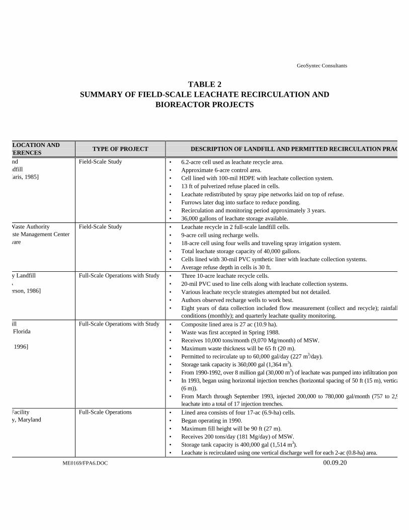
GeoSyntec Consultants
ME0169/FPA6.DOC 00.09.20
TABLE 2SUMMARY OF FIELD-SCALE LEACHATE RECIRCULATION AND
BIOREACTOR PROJECTS
LOCATION ANDFERENCES
TYPE OF PROJECT DESCRIPTION OF LANDFILL AND PERMITTED RECIRCULATION PRACTICES
ndndfill
Maris, 1985]
Field-Scale Study • 6.2-acre cell used as leachate recycle area.• Approximate 6-acre control area.• Cell lined with 100-mil HDPE with leachate collection system.• 13 ft of pulverized refuse placed in cells.• Leachate redistributed by spray pipe networks laid on top of refuse.• Furrows later dug into surface to reduce ponding.• Recirculation and monitoring period approximately 3 years.• 36,000 gallons of leachate storage available.
Waste Authorityaste Management Centerware
Field-Scale Study • Leachate recycle in 2 full-scale landfill cells.• 9-acre cell using recharge wells.• 18-acre cell using four wells and traveling spray irrigation system.• Total leachate storage capacity of 40,000 gallons.• Cells lined with 30-mil PVC synthetic liner with leachate collection systems.• Average refuse depth in cells is 30 ft.
y LandfillAerson, 1986]
Full-Scale Operations with Study • Three 10-acre leachate recycle cells.• 20-mil PVC used to line cells along with leachate collection systems.• Various leachate recycle strategies attempted but not detailed.• Authors observed recharge wells to work best.• Eight years of data collection included flow measurement (collect and recycle); rainfall; landfill surface
conditions (monthly); and quarterly leachate quality monitoring.ill Florida
, 1996]
Full-Scale Operations with Study • Composite lined area is 27 ac (10.9 ha).• Waste was first accepted in Spring 1988.• Receives 10,000 tons/month (9,070 Mg/month) of MSW.• Maximum waste thickness will be 65 ft (20 m).• Permitted to recirculate up to 60,000 gal/day (227 m3/day).• Storage tank capacity is 360,000 gal (1,364 m3).• From 1990-1992, over 8 million gal (30,000 m3) of leachate was pumped into infiltration ponds.• In 1993, began using horizontal injection trenches (horizontal spacing of 50 ft (15 m), vertical spacing of 20 ft
(6 m)).• From March through September 1993, injected 200,000 to 780,000 gal/month (757 to 2,950 m
leachate into a total of 17 injection trenches.Facilityy, Maryland
Full-Scale Operations • Lined area consists of four 17-ac (6.9-ha) cells.• Began operating in 1990.• Maximum fill height will be 90 ft (27 m).• Receives 200 tons/day (181 Mg/day) of MSW.• Storage tank capacity is 400,000 gal (1,514 m3).• Leachate is recirculated using one vertical discharge well for each 2-ac (0.8-ha) area.

GeoSyntec Consultants
ME0169/FPA6.DOC 00.09.20
LOCATION ANDFERENCES
TYPE OF PROJECT DESCRIPTION OF LANDFILL AND PERMITTED RECIRCULATION PRACTICES
ly, Florida
Full-Scale Operations • Current lined area is 7 ac (2.8 ha), with plans to expand to 22 ac (8.9 ha).• Began operating in 1992.• Maximum fill height will be 54 ft (16.5 m).• Receives 120 tons/day (109 Mg/day) of MSW.• Aeration lagoon capacity is 50,000 gal (189 m3).• Permitted to recirculate using surface ponds or spraying, provided spraying is limited to a 2-week duration
at any one location.fill Georgia
Full-Scale Operations • The ultimate lined area will be 40 ac (16 ha).• Individual cells, 3.5 to 4 ac (1.5 to 1.6 ha) in area, are constructed approximately every 7 months.• Maximum fill height will be approximately 60 ft (18 m).• Receives 600 ton/day (544 Mg/day) of MSW.• Lagoon capacity is 821,000 gal (3,100 m3 ).• Horizontal leachate injection trenches are constructed on top of each waste lift; the previous lift of
trenches is abandoned when each new lift of trenches is constructed.• Cover soil is removed prior to subsequent waste placement.
ashington Valley Secure
ampshire
Full-Scale Operations • Composed of eight hydraulically separated double-lined cells, each 0.75 to 1.0 ac (0.3 to 0.4 ha) in area.• Receives 10,000 to 15,000 tons/yr (9,070 to 13,600 Mg/yr) of MSW• Storage tank capacity is 10,000 gal (38 m3).• Filling began in January 1992, and was temporarily discontinued in November 1993.• Leachate was recirculated primarily by pre-wetting using a fire hose and also using a pipe manifold placed
in a shallow excavation in daily cover.Coastal Regional Solid Waste
thority LandfillFull-Scale Operations • Consists of three hydraulically separated cells totaling 22 ac (8 ha) in area.
• Final waste height will be approximately 50 ft (15 m).• Receives 350 tons/day (318 Mg/day) of MSW.• Aeration lagoon capacity is 2.4 million gal (9,085 m3).• Leachate is injected using a movable vertical injection system consisting of 12 10-ft (3-m) long perforated
black iron probes inserted into the landfill and connected to a manifold.• The system stays in one location for 2 to 8 days.• Leachate is injected at a pressure of 45 psi (310 kPa).• At the completion of each of the four planned lifts, horizontal trenches will be constructed in a pattern
radiating from a central distribution box. Each lift of trenches will be abandoned when the subsequent liftof trenches is constructed.
s, Missouri
Full-Scale Operations • Ultimate fill area will be 75 ac (30 ha).• Maximum fill height will be 85 ft (26 m).• Receives 300 tons/day (272 Mg/day) of MSW.• Lagoon storage capacity is 867,800 gal (3,280 m3).• Leachate recirculation will be performed using vertical discharge wells located at 200-ft (61-m) intervals.• Leachate will be managed using two lagoons: the first lagoon will collect leachate until recirculation
reduces leachate strength significantly, at which time leachate will be diverted to the second lagoon andused to irrigate closed areas of the landfill.

GeoSyntec Consultants
ME0169/FPA6.DOC 00.09.20
LOCATION ANDFERENCES
TYPE OF PROJECT DESCRIPTION OF LANDFILL AND PERMITTED RECIRCULATION PRACTICES
llNew York
Full-Scale Operations with Study • The bioreactor research project involves three hydraulically separated double composite lined cellsvarying from 5.4 to 7.4 ac (2.2 to 3 ha) in area.
• One cell serves as a control (i.e., no recirculation); two different horizontal leachate injection systems areused in the other two cells.
• Cell 2 has horseshoe-shaped injection trenches at three elevations, and a storage tank capacity of 20,000gal (76 m3).
• Cell 3 has horizontal trenches at two elevations containing pre-fabricated infiltrators, and a storage tankcapacity of 20,000 gal (76 m3).
• The relative moisture content of the waste will be monitored using gypsum blocks located in the waste.Waste Authority
Southern Solid Waste Management
Delawareki, 1996]
Full-Scale Operations • Leachate was recirculated in Cells 1 and 2 using vertical injection wells from 1985 to 1994.• For Cell 3, a horizontal integrated leachate recirculation and landfill gas extraction system is planned; lifts
of separate injection and extraction trenches will be installed every 20 ft (3 m) vertically.
unty Landfillunty, Virginiae Permit No. 531]
Full-Scale Operations • Leachate is injected into horizontal trenches filled with shredded tires.• The landfill is operated by USA Waste.
illy, GeorgiaWaste Permit No. 028-
Full-Scale Operations • Leachate is injected into horizontal trenches.• The landfill is operated by USA Waste.
ndfillessee Waste Permit No. SNL-
Full-Scale Operations • Leachate is sprayed into the working face.• The landfill is operated by USA Waste.
dfillessee
[Tennessee Solid Waste Permit Number8 EXT]
Full-Scale Operations • Leachate is sprayed into the working face.• The landfill is operated by USA Waste.
ion Landfilltucky
[Kentucky Solid Waste Permit Number
Full-Scale Operations • Leachate is sprayed into the working face.• The landfill is operated by USA Waste.
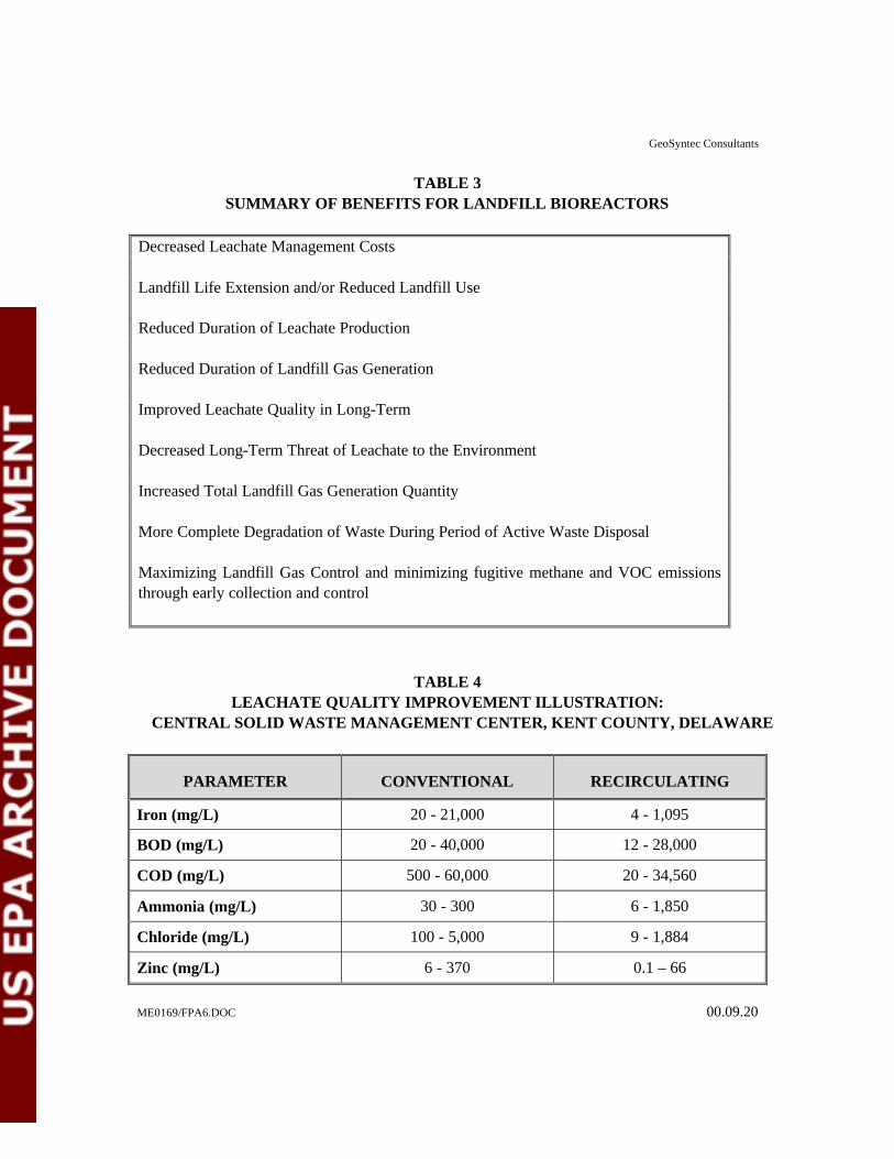
GeoSyntec Consultants
ME0169/FPA6.DOC 00.09.20
TABLE 3SUMMARY OF BENEFITS FOR LANDFILL BIOREACTORS
Decreased Leachate Management Costs
Landfill Life Extension and/or Reduced Landfill Use
Reduced Duration of Leachate Production
Reduced Duration of Landfill Gas Generation
Improved Leachate Quality in Long-Term
Decreased Long-Term Threat of Leachate to the Environment
Increased Total Landfill Gas Generation Quantity
More Complete Degradation of Waste During Period of Active Waste Disposal
Maximizing Landfill Gas Control and minimizing fugitive methane and VOC emissionsthrough early collection and control
TABLE 4LEACHATE QUALITY IMPROVEMENT ILLUSTRATION:
CENTRAL SOLID WASTE MANAGEMENT CENTER, KENT COUNTY, DELAWARE
PARAMETER CONVENTIONAL RECIRCULATING
Iron (mg/L) 20 - 21,000 4 - 1,095
BOD (mg/L) 20 - 40,000 12 - 28,000
COD (mg/L) 500 - 60,000 20 - 34,560
Ammonia (mg/L) 30 - 300 6 - 1,850
Chloride (mg/L) 100 - 5,000 9 - 1,884
Zinc (mg/L) 6 - 370 0.1 – 66
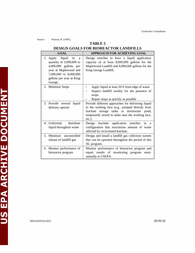
GeoSyntec Consultants
ME0169/FPA6.DOC 00.09.20
Source: Watson, R. [1995].
TABLE 5DESIGN GOALS FOR BIOREACTOR LANDFILLS
GOAL APPROACH FOR ACHIEVING GOAL
1. Apply liquid in aquantity of 3,000,000 to4,000,000 gallons peryear at Maplewood and7,000,000 to 8,000,000gallons per year at KingGeorge.
Design trenches to have a liquid applicationcapacity of at least 8,000,000 gallons for theMaplewood Landfill and 8,000,000 gallons for theKing George Landfill.
2. Minimize Seeps • Apply liquid at least 50 ft from edge of waste• Inspect landfill weekly for the presence of
seeps• Repair seeps as quickly as possible
3. Provide several liquiddelivery options
Provide different approaches for delivering liquidto the working face (e.g., pumped directly fromleachate storage tanks or stormwater pond,temporarily stored in tanks near the working face,etc.).
4. Uniformly distributeliquid throughout waste
Design leachate application trenches in aconfiguration that maximizes amount of wasteaffected by recirculated leachate.
5. Minimize uncontrolledrelease of landfill gas
Design and install a landfill gas collection systemthat can be operated throughout the period of thisXL program.
6. Monitor performance ofbioreactor program
Monitor performance of bioreactor program andreport results of monitoring program semi-annually to USEPA.

ME0169/FPA6.DOC 00.09.20
TABLE 6METHODS FOR MEASURING ENVIRONMENTAL PERFORMANCE OF
LANDFILL BIOREACTOR PROGRAM
CRITERIA DESCRIPTION APPLICATION
Settlement Measurement of total settlement ofsurface of waste over a period oftime
Compare the surveyed elevation of the top surface of the bioreactor before bioreactoroperation to the elevation during and after bioreactor operation
Leachate Quantity Total volume of leachate collectedfrom bioreactor cell
Measure leachate quantity from flowmeters in leachate riser houses located at eachbioreactor cell
Leachate Quality Chemical characteristics of leachatecollected from a bioreactor cell
Perform Laboratory analysis of the chemical characteristics of leachate frombioreactor cells
In-Place Density Unit weight of waste in a bioreactorcell
Divide the total weight of waste placed in a bioreactor cell (based on scale records) bythe total surveyed volume of the waste (i.e., difference in elevation between thebottom and the top of the bioreactor cell)
Odors Potential complaints of odors fromsite
Track frequency of odor complaints during and after liquids application events
Seeps Breakouts of leachate on sideslopes Track occurrence of seeps and correlate them to liquids application events
Operational Problems Assess operational efficiency causedby liquids application
Monitor the working face for occurrences of operational problems caused by liquidsapplications
Leachate Collection Systems Liquid quantity occurring in thedetection zone
Compare liquid flowrate in detection zone during liquids application period toflowrate in detection zone before liquids application period
Air Quality Measure emissions of releases oflandfill gas
Verify that permit-specified air quality standards are not being exceeded and, ifnecessary, assure landfill gas collection and/or treatment system to restore compliance

GeoSyntec Consultants
ME0169/FPA6.DOC 00.09.20
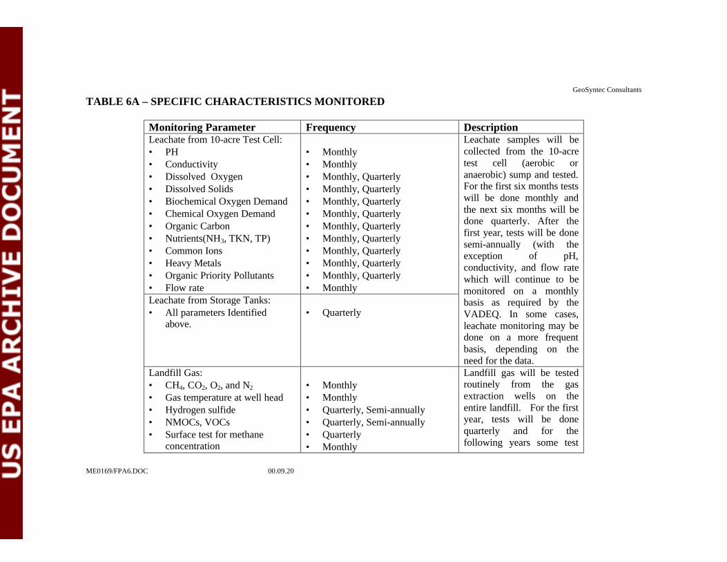
GeoSyntec Consultants
ME0169/FPA6.DOC 00.09.20
TABLE 6A – SPECIFIC CHARACTERISTICS MONITORED
Monitoring Parameter Frequency DescriptionLeachate from 10-acre Test Cell:• PH• Conductivity• Dissolved Oxygen• Dissolved Solids• Biochemical Oxygen Demand• Chemical Oxygen Demand• Organic Carbon• Nutrients(NH3, TKN, TP)• Common Ions• Heavy Metals• Organic Priority Pollutants• Flow rate
• Monthly• Monthly• Monthly, Quarterly• Monthly, Quarterly• Monthly, Quarterly• Monthly, Quarterly• Monthly, Quarterly• Monthly, Quarterly• Monthly, Quarterly• Monthly, Quarterly• Monthly, Quarterly• Monthly
Leachate from Storage Tanks:• All parameters Identified
above.• Quarterly
Leachate samples will becollected from the 10-acretest cell (aerobic oranaerobic) sump and tested.For the first six months testswill be done monthly andthe next six months will bedone quarterly. After thefirst year, tests will be donesemi-annually (with theexception of pH,conductivity, and flow ratewhich will continue to bemonitored on a monthlybasis as required by theVADEQ. In some cases,leachate monitoring may bedone on a more frequentbasis, depending on theneed for the data.
Landfill Gas:• CH4, CO2, O2, and N2
• Gas temperature at well head• Hydrogen sulfide• NMOCs, VOCs• Surface test for methane
concentration
• Monthly• Monthly• Quarterly, Semi-annually• Quarterly, Semi-annually• Quarterly• Monthly
Landfill gas will be testedroutinely from the gasextraction wells on theentire landfill. For the firstyear, tests will be donequarterly and for thefollowing years some test
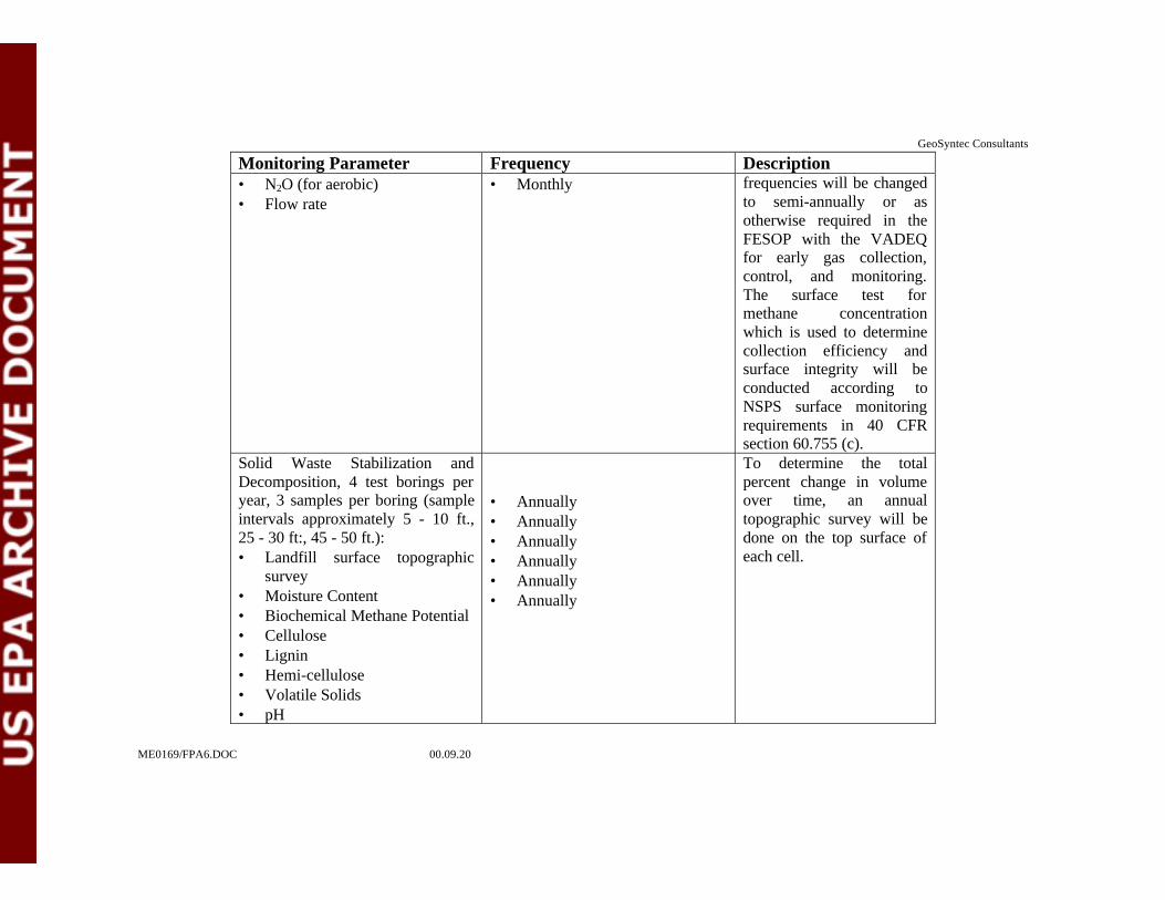
GeoSyntec Consultants
ME0169/FPA6.DOC 00.09.20
Monitoring Parameter Frequency Description• N2O (for aerobic)• Flow rate
• Monthly frequencies will be changedto semi-annually or asotherwise required in theFESOP with the VADEQfor early gas collection,control, and monitoring.The surface test formethane concentrationwhich is used to determinecollection efficiency andsurface integrity will beconducted according toNSPS surface monitoringrequirements in 40 CFRsection 60.755 (c).
Solid Waste Stabilization andDecomposition, 4 test borings peryear, 3 samples per boring (sampleintervals approximately 5 - 10 ft.,25 - 30 ft:, 45 - 50 ft.):• Landfill surface topographic
survey• Moisture Content• Biochemical Methane Potential• Cellulose• Lignin• Hemi-cellulose• Volatile Solids• pH
• Annually• Annually• Annually• Annually• Annually• Annually
To determine the totalpercent change in volumeover time, an annualtopographic survey will bedone on the top surface ofeach cell.
GeoSyntec Consultants
ME0169/FPA6.DOC 00.09.20
Monitoring Parameter Frequency Description
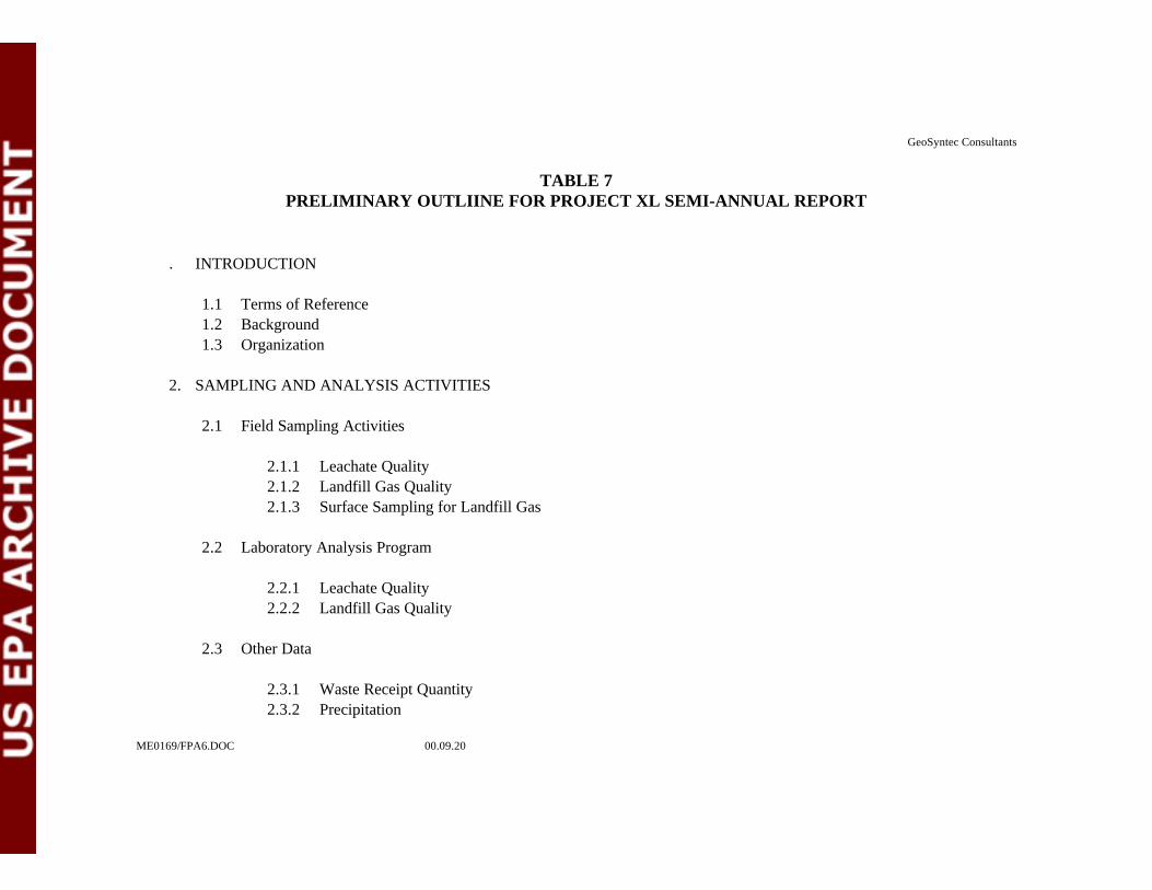
GeoSyntec Consultants
ME0169/FPA6.DOC 00.09.20
TABLE 7PRELIMINARY OUTLIINE FOR PROJECT XL SEMI-ANNUAL REPORT
. INTRODUCTION
1.1 Terms of Reference1.2 Background1.3 Organization
2. SAMPLING AND ANALYSIS ACTIVITIES
2.1 Field Sampling Activities
2.1.1 Leachate Quality2.1.2 Landfill Gas Quality2.1.3 Surface Sampling for Landfill Gas
2.2 Laboratory Analysis Program
2.2.1 Leachate Quality2.2.2 Landfill Gas Quality
2.3 Other Data
2.3.1 Waste Receipt Quantity2.3.2 Precipitation

GeoSyntec Consultants
ME0169/FPA6.DOC 00.09.20
2.3.3 Leachate Generation Quantities2.3.4 Quantity of Liquid Applied to Landfills2.3.5 Landfill Settlement2.3.6 Landfill Gas Volume
3. DATA ANALYSIS
3.1 Maplewood Recycling and Waste Disposal Facility
3.1.1 Leachate Quality and Quantity3.1.2 Landfill Gas Quality and Quantity3.1.3 Trends in Other Data3.1.4 Control Cell Data
3.2 King George County Landfill and Recycling Center
3.2.1 Leachate Quality, Leachate and Stormwater Quantity3.2.2 Landfill Gas Quality and Quantity3.2.3 Trends in Other Data3.2.4 Control Cell Data
4. CONCLUSIONS
4.1 Leachate Quality and Quantity4.2 Landfill Gas Generation Quantity and Control4.3 Relative Effectiveness of Trenches Versus Wells4.4 Relative Performance of Leachate Recirculation Versus Bioreactor Landfill
GeoSyntec Consultants
ME0169/FPA6.DOC 00.09.20
Appendix A: Field Sampling LogsAppendix B: Laboratory Test Results
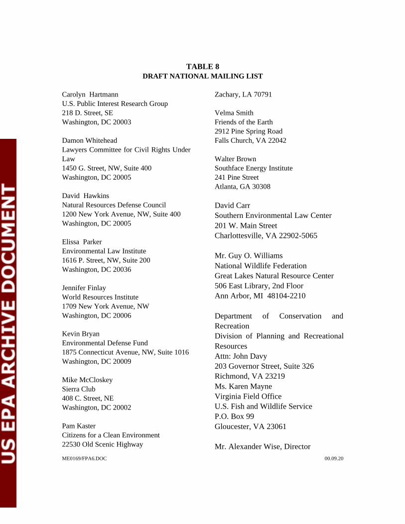
ME0169/FPA6.DOC 00.09.20
TABLE 8DRAFT NATIONAL MAILING LIST
Carolyn HartmannU.S. Public Interest Research Group218 D. Street, SEWashington, DC 20003
Damon WhiteheadLawyers Committee for Civil Rights UnderLaw1450 G. Street, NW, Suite 400Washington, DC 20005
David HawkinsNatural Resources Defense Council1200 New York Avenue, NW, Suite 400Washington, DC 20005
Elissa ParkerEnvironmental Law Institute1616 P. Street, NW, Suite 200Washington, DC 20036
Jennifer FinlayWorld Resources Institute1709 New York Avenue, NWWashington, DC 20006
Kevin BryanEnvironmental Defense Fund1875 Connecticut Avenue, NW, Suite 1016Washington, DC 20009
Mike McCloskeySierra Club408 C. Street, NEWashington, DC 20002
Pam KasterCitizens for a Clean Environment22530 Old Scenic Highway
Zachary, LA 70791
Velma SmithFriends of the Earth2912 Pine Spring RoadFalls Church, VA 22042
Walter BrownSouthface Energy Institute241 Pine StreetAtlanta, GA 30308
David CarrSouthern Environmental Law Center201 W. Main StreetCharlottesville, VA 22902-5065
Mr. Guy O. WilliamsNational Wildlife FederationGreat Lakes Natural Resource Center506 East Library, 2nd FloorAnn Arbor, MI 48104-2210
Department of Conservation andRecreationDivision of Planning and RecreationalResourcesAttn: John Davy203 Governor Street, Suite 326Richmond, VA 23219Ms. Karen MayneVirginia Field OfficeU.S. Fish and Wildlife ServiceP.O. Box 99Gloucester, VA 23061
Mr. Alexander Wise, Director

GeoSyntec Consultants
ME0169/FPA6.DOC 00.09.20
Department of Historic Resources2801 Kensington AvenueRichmond, VA 23221
Ms. Perida Giles, Policy AnalystVirginia Department of Agriculture andConsumer ServicesP.O. Box 1163Richmond, VA 23209
Dr. Anne Patterson,Acting CommissionerVirginia Department of HealthP.O. Box 2448Richmond, VA 23219
Mr. Wayne Sterling, DirectorDepartment of Economic Development901 East Byrd StreetRichmond, VA 23218-0798
Phillip VannoorbeeckCounty Administrator16441 Court StreetP.O. Box AAmelia, VA 23002
Jim BennettBoard of Supervisors12440 Fowlkes Bridge RoadAmelia, VA 23002
A. Taylor Harvie, IIIBoard of Supervisors12901 Coverly RoadAmelia, VA 23002
Ralph A. Whitaker, Jr.Board of Supervisors7010 Dennisville RoadAmelia, VA 23002
Charles E. KeenerBoard of Supervisors10531 Mount Zion RoadJetersville, VA 23083
Franklin D. HarrisBoard of Supervisors2901 Crayton RoadAmelia, VA 23002
Raymond T. JohnsonMaplewood Landfill AdvisoryCommitteeP.O. Box 456Jetersville, VA 23083
Tom AshtonMaplewood Landfill AdvisoryCommitteeP.O. Box 528Amelia, VA 23002
Diane RichardsMaplewood Landfill AdvisoryCommitteeP.O. Box 313Amelia, VA 23002
GeoSyntec Consultants
ME0169/FPA6.DOC 00.09.20
Thomas HarrisCounty AdministratorKing George County10459 Courthouse Drive, Suite 200King George, VA 22485
Jason PauleyKing George County RepresentativeKing George Landfill10376 Bullock DriveKing George, VA 22485
Timothy J. SchotschWaste Management RepresentativeKing George Landfill10376 Bullock DriveKing George, VA 22485
J. Dennis Sawdy, ChairmanKing George Solid Waste AdvisoryCommittee13350 Round Hill RoadKing George, VA 22485
Pearl A. SmithP.O. Box 491Dahlgren, VA 22448
Tommy Tschirn4491 Willow Tree LaneKing George, VA 22485
Ron Wood9217 Indian Springs DriveKing George, VA 22485
Mike PollardP.O. Box 4Jersey, VA 22481Charles HartP.O. Box 190Sealston, VA 22547
Phyllis CookResident and Journal Reporter10563 Eisenhower DriveKing George, VA 22485
Ray YorkP.O. Box AAmelia, VA 23002
Bruce SpringerP.O. Box 865Amelia, VA 23002
Pam Hood12620 Hawbranch LaneAmelia, VA 23083
Patty Averett5201 Buckskin CreekJetersville, VA 23083
M.D. SalstsrP.O. Box 123Amelia, VA 23002

GeoSyntec Consultants
ME0169/FPA6.DOC 00.09.20
Lou FosterP.O. Box 932King George, VA 22485

ME0169/FPA6.DOC

GeoSyntec Consultants
ME0169/FPA6.DOC 00.09.20

GeoSyntec Consultants
ME0169/FPA6.DOC 00.09.20
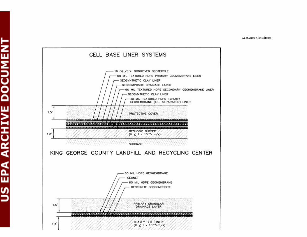
GeoSyntec Consultants
ME0169/FPA6.DOC 00.09.20

GeoSyntec Consultants
ME0169/FPA6.DOC 00.09.20
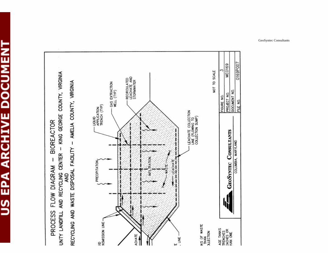
GeoSyntec Consultants
ME0169/FPA6.DOC 00.09.20

GeoSyntec Consultants
ME0169/FPA6.DOC 00.09.20
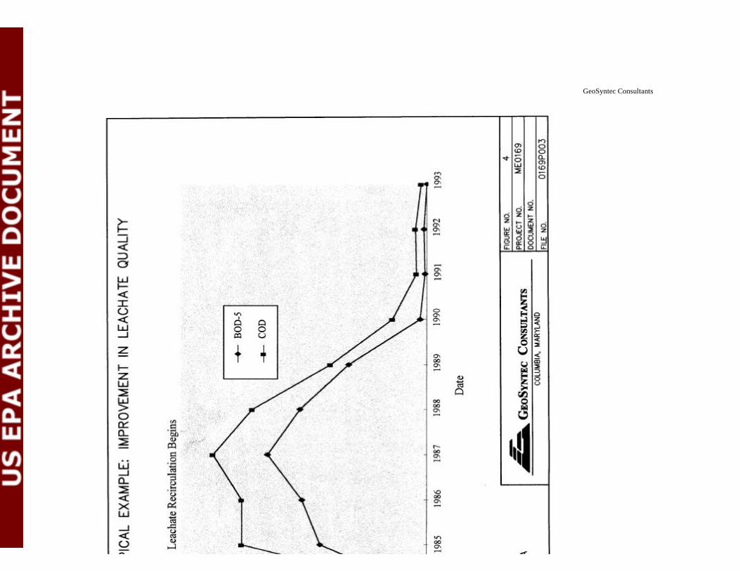
GeoSyntec Consultants
ME0169/FPA6.DOC 00.09.20

GeoSyntec Consultants
ME0169/FPA6.DOC 00.09.20

GeoSyntec Consultants
ME0169/FPA6.DOC 00.09.20

GeoSyntec Consultants
ME0169/FPA6.DOC 00.09.20
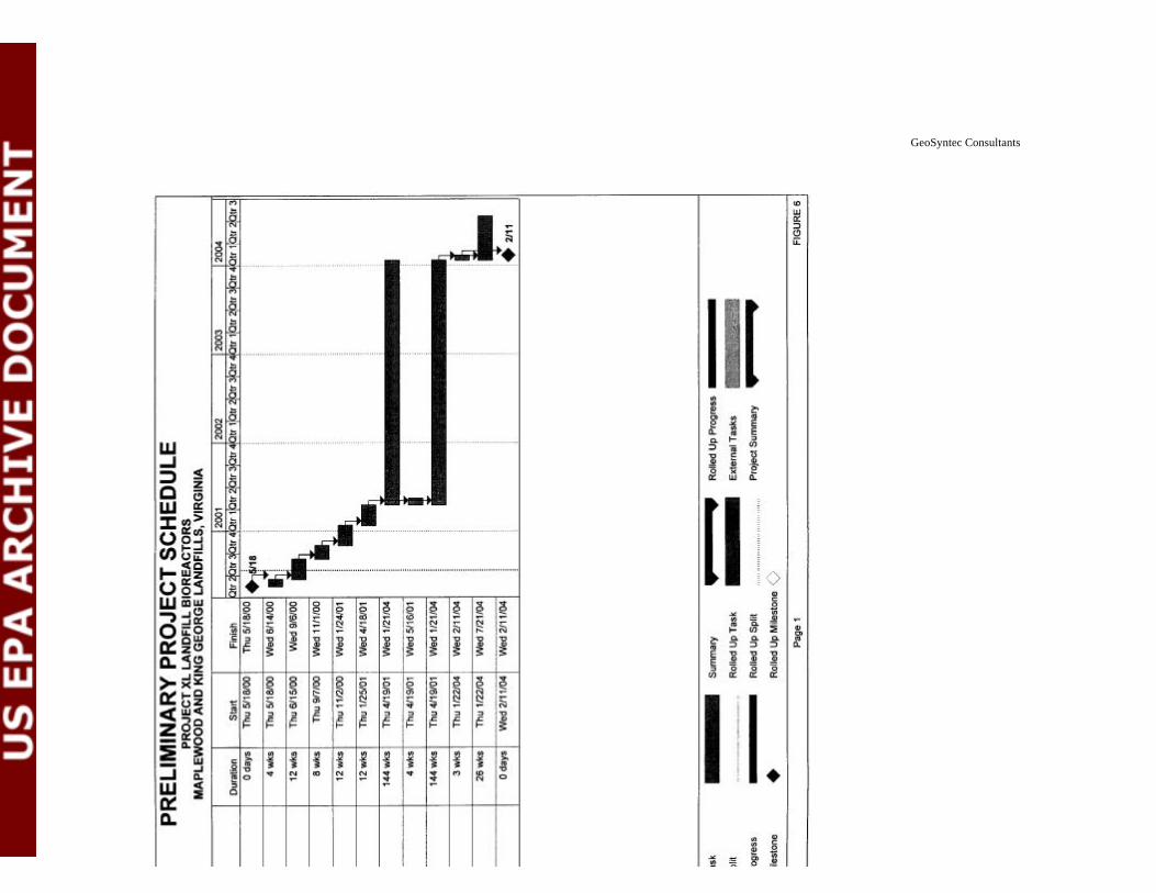
GeoSyntec Consultants
ME0169/FPA6.DOC 00.09.20