Project Report in Robotics and Autonomous Systems€¦ · Project Report, Mech Warrior Page 3(23)...
23
Project Report, Mech Warrior Page 1(23) 2D1426 Robotics and Autonomous Systems, KTH, Stockholm Oct. 2003 Mech Warrior Project Report in Robotics and Autonomous Systems Ken Grapenqvist, [email protected] Mattias Thulin, [email protected] Johan Vallin, [email protected] October, 2003
Transcript of Project Report in Robotics and Autonomous Systems€¦ · Project Report, Mech Warrior Page 3(23)...

Project Report, Mech Warrior Page 1(23) 2D1426 Robotics and Autonomous Systems, KTH, Stockholm Oct. 2003
Mech Warrior
Project Report in Robotics and Autonomous Systems
Ken Grapenqvist, [email protected] Mattias Thulin, [email protected] Johan Vallin, [email protected]
October, 2003

Project Report, Mech Warrior Page 2(23) 2D1426 Robotics and Autonomous Systems, KTH, Stockholm Oct. 2003
Abstract This is the final report in the course 2D1426 Robotics and Autonomous Systems, given
at KTH in the autumn of 2003. It describes the construction of an autonomous robot able to play one-on-one robot floor hockey, and analyzes the mechanical design, implemented electronic components and software solutions as well as the results obtained. Photos, circuit diagrams and source code are attached in an appendix.

Project Report, Mech Warrior Page 3(23) 2D1426 Robotics and Autonomous Systems, KTH, Stockholm Oct. 2003
Table of Contents ABSTRACT..........................................................................................................................................................2 TABLE OF CONTENTS ...................................................................................................................................3 1 INTRODUCTION............................................................................................................................................4
1.1 OBJECTIVE ................................................................................................................................................... 4 1.2 ROBOT RESTRICTIONS................................................................................................................................ 4 1.3 ROBOT FLOOR HOCKEY RULES................................................................................................................ 5 1.4 AVAILABLE MATERIAL .............................................................................................................................. 5
2 BASIC STRATEGIC DESIGNS..................................................................................................................7 3.1 PROGRAMMING ENVIRONMENT................................................................................................................ 8 3.2 MAIN BOARD............................................................................................................................................... 8 3.3 ADDTIONAL ELECTRONICS........................................................................................................................ 8
4 METHOD AND SOLUTIONS .....................................................................................................................9
4.1 PHYSICAL STRUCTURE............................................................................................................................... 9 4.2 LOCOMOTION .............................................................................................................................................. 9 4.3 SENSORS..................................................................................................................................................... 10 4.3.1 TARGET SENSORS .................................................................................................................................. 10 4.3.2 LOCOMOTION SENSORS ........................................................................................................................ 11 4.3.3 FLOOR SENSORS..................................................................................................................................... 11 4.3.4 MECHANICAL SENSORS ........................................................................................................................ 11 4.4 MAKING GOAL .......................................................................................................................................... 12 4.5 SOFTWARE ................................................................................................................................................. 12 4.5.1 AVOID DEFENSIVE GOAL-CIRCLE........................................................................................................ 12 4.5.2 SCORE ..................................................................................................................................................... 13 4.5.3 AVOID OFFENSIVE GOAL-CIRCLE ........................................................................................................ 13 4.5.4 SPECIAL MOVE....................................................................................................................................... 13 4.5.5 MOVE TO PUCK OR OFFENSIVE GOAL ................................................................................................. 13
5 RESULTS .........................................................................................................................................................14 6 CONCLUSIONS.............................................................................................................................................14 7 APPENDIX ......................................................................................................................................................17
7.1 PARTS LIST................................................................................................................................................. 17 7.2 SOURCE CODE IN C................................................................................................................................... 17

Project Report, Mech Warrior Page 4(23) 2D1426 Robotics and Autonomous Systems, KTH, Stockholm Oct. 2003
1 Introduction
1.1 Objective This is a project report from the course 2D1426 Robotics and Autonomous Systems,
given at the Royal Institute of Technology in Stockholm in the autumn of 2003. The goal of the course is to give the student a general knowledge in the field of Robotics with its possibilities and limitations as well as practice in building and programming an autonomous robot. As an introduction lectures were given on the fundamentals concepts of robotics, such as kinematics, navigation and digital control.
The practical part of the course was performed in project groups of three persons
per group. The objective of this project was to build an autonomous purpose oriented robot that works towards pre-defined goals taking decisions based on information from its sensors. The task performed by the robot was a game of ‘robot hockey’ where the robot was supposed to find the puck and then score a goal with it, always observing the rules of the game. This was to be done unopposed as well as opposed by robots from the other project groups in a tournament at the end of the course.
Using information from the lectures the project groups were supposed to make
their robots perform this task implementing individual solutions to all problems encountered in the construction and programming process. Although the material to construct the robot was available in the lab, as well as a sample program for implementing some basic software solutions, the project groups were free to use their own imagination to obtain a working robot, however observing some basic rules and restrictions.
1.2 Robot restrictions To give the students a guideline as how to build their robots, as well as making
the tournament fair, some constraints were defined for the robot [Lecture 3, 2003]: • A robot must fit in a circle with diameter 250mm (excluding flexible parts
or the stick). • The stick may extend no more than one puck diameter from the robot
body. The part of the stick outside the robot body must not be wider than one puck radius, and may not have any joints or concavities. It must be at least 2cm high.
• The robot is not allowed to grab the puck, and the edge of the vertical projection of the robot body on the floor may not have any concave parts. Any protruding whiskers or bumpers must be flexible enough so that they cannot be used to move or guide the puck. The robot must be constructed so that the puck cannot be on top of any part of the robot.
• No device that can harm the opposing robot, on purpose or not, may be mounted on a robot.

Project Report, Mech Warrior Page 5(23) 2D1426 Robotics and Autonomous Systems, KTH, Stockholm Oct. 2003
• When guiding the puck, the stick must not occult the IR LED’s of the puck.
1.3 Robot Floor Hockey rules
• Robot floor hockey is performed on a rink, which is 2.5m long, and 1.5m wide. The floor of the rink is white, except for a black midline and a black arc of radius 10cm marking the goal zone. The goal itself is marked by red floor color of about 3cm radius [Lecture 3, 2003].
• Matches are three minutes long except for semi-finals (4min) and final (5min). There is only one robot on each team.
• The matches have no breaks whatsoever. • When the game starts both robots are in their defensive goal zones. • A goal is scored whenever the puck is partly within the red zone at the
goal aluminum plate; the goal zone rule has not been violated (see below). The scoring robot also has to signal the goal by playing its own pre-defined tune on its speaker. After each scored goal the puck will be moved to the centre point.
• A robot may only signal a goal directly after it has tried to score. Other signaling will render the robot 10 seconds off the rink.
• When a robot goes past the white line an inch into its own defensive goal zone with any non-flexible part (excluding the stick), it will be taken off the rink for 10 seconds and then put back far from the puck. The goal zones are marked by black paint on the floor, as is the centre line.
• When a robot scores, it may not go past the white line in the goal zone with any nonflexible part (excluding the stick). If it does the scored goal is not counted. If the puck is left in the goal zone without scoring it will be moved to the centre point 3 s after a robot last touched it.
• A robot that is pushed into a goal zone and is constantly working to get out of it will receive no penalty (i.e. the any goal is approved or the robot is not taken of the rink).
• If a robot brakes down during a match, it may be taken off the floor for repair for a minimum of 30 s and then put back far from the puck.
1.4 Available material The main parts of the robots were provided by the course staff. These consisted
in [FejkOPaque, 2003]:
• Microcontroller PIC16F877: A single chip microcontroller unit with 20MHz processor, 368 bytes of RAM and 8k x 14 bits of program memory.
• Motherboard: a purpose built board with connections for the microcontroller, motors, LCD screen, RS232 (serial port), IR sensors and

Project Report, Mech Warrior Page 6(23) 2D1426 Robotics and Autonomous Systems, KTH, Stockholm Oct. 2003
multi use analogue I/O. It also includes a voltage booster card for the motors, a two row LCD screen and a 100 ohm miniature speaker.
• Motors: Two 12V DC motors • Sensors: IR and reflex sensors for detecting the puck, the goal,
movement and rink sections and switches for bumpers etc. • Chassis material: LEGO and Meccano • Power supply: A rechargeable 7.2V NiCd battery.
In addition there were lots of tools and material available in the robotics lab.
Project Report, Mech Warrior Page 7(23) 2D1426 Robotics and Autonomous Systems, KTH, Stockholm Oct. 2003
2 Basic strategic designs The work was concentrated on making a small and maneuverable robot that
would take advantage of its speed when opposed with an enemy robot. Initially a firing mechanism was considered, but after serious consideration and tests the idea was abolished and efforts were instead aimed at a software solution that would orient the robot to score goals utilizing its stick.
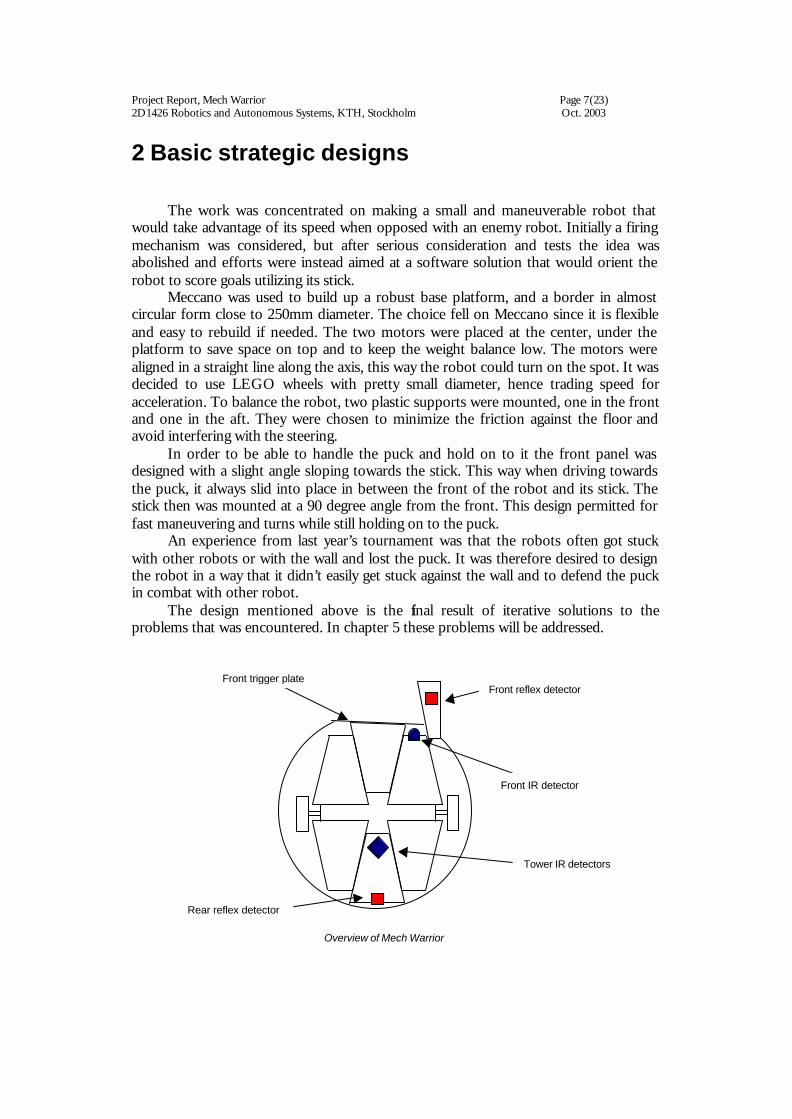
Meccano was used to build up a robust base platform, and a border in almost circular form close to 250mm diameter. The choice fell on Meccano since it is flexible and easy to rebuild if needed. The two motors were placed at the center, under the platform to save space on top and to keep the weight balance low. The motors were aligned in a straight line along the axis, this way the robot could turn on the spot. It was decided to use LEGO wheels with pretty small diameter, hence trading speed for acceleration. To balance the robot, two plastic supports were mounted, one in the front and one in the aft. They were chosen to minimize the friction against the floor and avoid interfering with the steering.
In order to be able to handle the puck and hold on to it the front panel was designed with a slight angle sloping towards the stick. This way when driving towards the puck, it always slid into place in between the front of the robot and its stick. The stick then was mounted at a 90 degree angle from the front. This design permitted for fast maneuvering and turns while still holding on to the puck.
An experience from last year’s tournament was that the robots often got stuck with other robots or with the wall and lost the puck. It was therefore desired to design the robot in a way that it didn’t easily get stuck against the wall and to defend the puck in combat with other robot.
The design mentioned above is the final result of iterative solutions to the problems that was encountered. In chapter 5 these problems will be addressed.
Front trigger plate
Front IR detector
Tower IR detectors
Overview of Mech Warrior
Front reflex detector
Rear reflex detector

Project Report, Mech Warrior Page 8(23) 2D1426 Robotics and Autonomous Systems, KTH, Stockholm Oct. 2003
3 Programming environment and electronics
3.1 Programming environment
All programming was done in Emacs and a tool called MPlab was used to compile the written code. The programming language that was used in the project was C. MPlab, which actually is a development environment, called a third party compiler to compile the code, Hi-Tech C. Hi-Tech C is not a full implementation of ANSI C, however it does implement some extra features to the language. For example: it's possible to choose where memory will be allocated by adding the bank keyword before variable declarations. The compiler generates hexadecimal code that can be directly transferred, with a utility called ntload, to the main processor in Mech Warrior.
3.2 Main board
On the main board there is a 20 Mhz PIC16F877 processor from Microchip that is used as main processor. The PIC16F877 has 8K x 14 bits FLASH program memory, 368 bytes of SRAM work memory and
256 bytes of EEPROM to store data that won't be cleard on power off or reset. The main processor handles communication with the co-procssor and PC with the serial RS232 interface, program logic, controlling the LCD display and input/output with some sensoros.
In addition to the PIC16F877 there is a co processor on the main board, a
PIC16F876. It's used to read values form infrared sensors. The main processor controls the motors. To its help it has four motordriving circuts contained in two integrated circuts. The so-called H-power bridges help increase the power in the pulse width modulation motorcontrol signal. More information about that can be found under the ”Sensors” and ”Locomotion” sections below.
Further more the main board contains some light emitting diodes, dip-switches,
pull-up resistors and inout/output ports to help in debugging the program logic and interface with other electronics
3.3 Addtional electronics
A Liquid crystal display was used to print out values on vaibles during run time for debugging and informational purposes. There was also a simple board, which was used in the communication with the PC to convert signal voltage level between PIC levels and RS-232 levels. A small board for driving the encoders and reflexdetectors was also carried by Mech Warrior. A voltage booster board was used to boost the 7,2 Volts that the NiCad cells gave in order to handle all the electonics voltage needs. In addition to all that several sensors and a couple of motors was mounted on the robot. They are described in more detail under the ”Sensors” and ”Locomotion” sections.

Project Report, Mech Warrior Page 9(23) 2D1426 Robotics and Autonomous Systems, KTH, Stockholm Oct. 2003
4 Method and solutions
4.1 Physical structure The robot was constructed on a strong chassis made out of Meccano, with an
almost circular border fencing in the wheels in order to avoid getting stuck against other robots or the wall. Functionality was to be emphasized rather than beauty. The front was made slightly inclined towards the stick to permit the puck slide into place in the space between front and stick where it could easily be maneuvered. For the stick various designs were tried out and it wasn’t until the final day that it was finally completed. Lego was used to construct the base and foam packing material was then used to give the stick its desired form. Finally, the inside was covered with rubber tape for maximum friction. The result was a triangular shape that proved very effective in maneuvering the puck.
To obtain balance the heavy battery pack was placed in the middle to not interfere with steering. Four IR detectors were placed at a high position on a pole at the center of the robot to allow a free line of sight at all angles. A fifth IR detector was placed at the front of the robot with the function to detect if the robot had the puck.
4.2 Locomotion The locomotion on Mech Warrior is based on differential drive. Differential drive
is based on two driving wheels that can be controlled separately but still have the same center axis. In addition to these wheels some kind of balancing support is required to stop the robot from tilting. Mech Warrior has a fixed Lego construction, with low friction material supporting the robot near the floor.
A fixed gearbox is mounted on each driving motor to gain more torque and
reduce rotation speed. The motors are controlled by the secondary PIC processor and accessed in the main PIC processor through an input/output port. The main PIC sends a PWM (pulse width modification) signal to an H-amplifier bridge. By modifying the pulse width, it’s possible to control the RMS (root mean square) voltage level to the DC (direct current) motors. Thereby it’s possible to set the angular velocity for each motor. The H-power Bridge enables the ability to easily change the rotation direction of the motors.
When Mech Warrior carried all the gear (motherboard, additional circuit boards,
battery etc), there was a threshold to get the robot moving at all. It took about 5/6 of full power to get some motion out of the robot. This wasn’t really a problem though because there where still margin to control different speeds.

Project Report, Mech Warrior Page 10(23) 2D1426 Robotics and Autonomous Systems, KTH, Stockholm Oct. 2003
4.3 Sensors
The robot had to have sensors to create a view of its world. In this project many different types of sensors were used. The following sections explain what kind of information the different sensors supplied to the robot control system. The sections are categorized on what the sensors was used for.
4.3.1 Target sensors
In order to steer the robot towards the current target, it somehow needs to know
where to go. The current is target is either the puck or the opponent’s goal if the puck already been found. In the strategy used on Mech Warrior the home goal can also be a target in certain situations. For example if the robot doesn’t have the puck and doesn’t see it, the robot goes toward its own goal to protect it.
Mech Warrior uses five infrared sensors to look for the targets. The infrared
sensors are controlled by the secondary PIC processor and accessed in the main PIC processor through an SPI serial interface. All the targets send out a signal of infrared light with a certain modulation frequency. Different targets have different frequencies. That way the robot has a very simple type of infrared vision. If something comes between the robot and the current target, for example the opponent, the robot is blinded. After a some testing it was concluded that a satisfying placement of the five infrared sensors on Mech Warrior was to place one in the front to detect if we had the puck or not, and the rest on a tower for navigation. The four infrared sensors on the tower were placed to handle one sector each: northwest, northeast, southwest and southeast if the robot is facing north. They are mounted tightly together to ensure we don’t have any dead angles where the robot is blind. These sensors where used to steer the robot towards its target, more on the subject is addressed in chapter 4.4.5 and the source code in appendix.
Furthermore a mechanical sensor was used to detect if we had the puck or not. It
was a micro switch, which was enabled if the robot had possession of the puck and otherwise disabled. Together with the front mounted infrared detector, a fault tolerant
Left IR detector
Right IR detector
Aft left IR detector
Aft right IR detector

Project Report, Mech Warrior Page 11(23) 2D1426 Robotics and Autonomous Systems, KTH, Stockholm Oct. 2003
system to detect puck was in place. This system determined the target to steer towards in the behavior model.
4.3.2 Locomotion sensors Pieces of plastic film were mounted directly on the backside of the motor rotors.
The film had for sectors. Two were transparent and two were colored black. The sectors split the round piece of film in four equally large sectors. Around the film two light emitters were placed on one side and two light detectors on the other side. All together they formed a rotation velocity encoder.
At first the velocity encoders were used to detect if Mech Warrior was stuck
somewhere and trigger behavior to handle that. It was however determined that this information with the resulting behavior decreased Mech Warriors performance. Therefore they were not used on the tournament or in the final source code
4.3.3 Floor sensors In order to avoid the goal zones the infrared steering sensors were used. Since the
infrared detectors gave a strength value, Mech Warrior was first programmed to avoid going nearer a certain goal than a predetermined combination of max values on the different infrared sensors. This was however not sufficient to program the robot to stay out of the goal zones at all times. Therefore these sensors were combined with reflex detectors. Since the tournament arena was painted in black and white, Mech Warrior distinguishes between two colors. This simplicity made it possible to use very cheap reflex detectors. A light emitting diode combined with a photo resistor that could react whether the floor surface was white or black. One reflex detector on the front and one on the rear in combination with the infrared detectors made it possible to create a behavior to avoid the goal zones.
4.3.4 Mechanical sensors The mechanical sensor is the front plate that triggers a contact closure sensor.
The role of the sensor was to detect if the robot had the puck in control but its function got less important since the front IR detector was mounted.

Project Report, Mech Warrior Page 12(23) 2D1426 Robotics and Autonomous Systems, KTH, Stockholm Oct. 2003
4.4 Software
Mech Warior scoring a goal
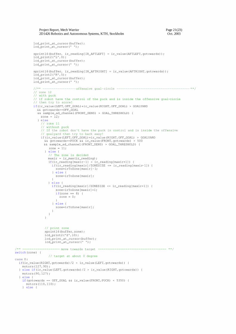
4.5 Software The robot logic is build upon a priority state machine. Which state to run is
almost solely dependent on what the IR detectors detects. And here are the states in priority:
• avoid defensive goal-circle • score • avoid offensive goal-circle • special move • move to puck/goal
4.5.1 Avoid defensive goal-circle The most prioritized state is to avoid own goal zone as the result of entering the
defensive goal-circle is penalty (taken off the rink). There are three ways the robot knows it’s about to enter the goal-circle. First way is to read off the left IR detector and compare it with a threshold value. This is because the robot doesn’t have a reflex detector on the left side. The other ways are to read off the reflex detectors and compare them with the threshold value. The action in this state is ether to drive forward or backward a few ms.

Project Report, Mech Warrior Page 13(23) 2D1426 Robotics and Autonomous Systems, KTH, Stockholm Oct. 2003
4.5.2 Score When the robot have the puck in control and is on the offensive zone it will
compare the front reflex detector with the threshold. If the reflex detector has a higher value, it indicates that the stick is inside the offensive goal -circle. The action in this state is to follow a timed procedure. It will drive back a bit and then push the puck in with the tip of the stick.
4.5.3 Avoid offensive goal-circle Not very important if the robot doesn’t have the puck. Thought, it’s not good to
enter the opponent’s goal-circle. There is no penalty connected to the offensive goal-circle if you are not trying to score. The way to avoid offensive goal-circle is similar to defensive goal-circle. The action in this state is to drive forward or back off, which ever that will avoid the offensive goal-circle.
4.5.4 Special move While testing the robot in the lab, a frequent phenomenon occurred. The puck
got stuck on the wrong side of the stick. This of course was not good. By using both the front IR detector and the tower detector and comparing them with threshold values, the robot can determine if the puck is stuck. The action in this state is a timed procedure. The robot will drive back a few ms, turn a bit right and then trap the puck.
4.5.5 Move to puck or offensive goal
start
avoid offensive goal zone
avoid defensive goal zone
move to puck
move to offensive goal
score
special move
With puck and entered offensive goal circlePrio 2 In control of the
puck and detects offensive goal Prio 1
In control of the puck and detects the offensive goal Prio 1
Detect puck Prio 2
Inside offen-sive goal circle. Prio 2
Inside defensive goal circle Prio 1
Inside defensive goal circle Prio 1
Principle state diagram
Puck on right side of st ick Prio 3

Project Report, Mech Warrior Page 14(23) 2D1426 Robotics and Autonomous Systems, KTH, Stockholm Oct. 2003
This is the least prioritized state, but the program will spend most of it’s time here. That is also why this state must be stable and optimized. In this state the robot starts with approximating where the target is. The target is either the puck or the offensive goal. The target can be in 8 different zones around the robot, and the zones are not equally in size. When the zone is determined the robot will turn on the spot the target is not in front of the robot. If the robot is in front of the robot (in zone 0) it will drive straight forward if the puck is straight ahead. The puck can be in front, but not exactly straight ahead, and then the robot will correct the course with easy left or right turns homing in on the puck.
5 Results The strategy to emphasize on a well trimmed and tested software and hardware
solution proved to be a big success in the robot tournament. As anticipated it quickly moved to the puck, was able to hold on to it when moving towards the goal. The scoring method had been tested and reconstructed repeatedly and was functioning with satisfaction during the final tests. However, in the tournament it presented some problems and managed to score only on every other attempt. In some goal attempts it entered the goal-circle and hence lost the score.
The robot behaved well throughout the tournament and the software design as well as the physical structure proved to be very robust as the robot didn’t have to be taken off the rink more than once. Using a circular border fence around the robot worked well in avoiding getting stuck with other robots. Unfortunately the stick sometimes got stuck with other robots which didn’t possess any protective feature.
At first the small LEGO wheels showed a tendency to spin when getting stuck against something, since the rubber in the wheels was made of a hard fabric. This was solved by gluing an extra layer of softer rubber on top of the wheel.
The decision not to use the speed information from the locomotion sensors to determine when the robot was stuck and hence back off was good. In close encounter fighting over the puck with its opponents the robot performed well using its aggressive technique and on most occasions won the puck.
6 Conclusions Mech Warrior behaved satisfactory during the tournament, where a very stable
program and well trimmed sensors made way for a fast and well functioning robot. The fact that it never had to be taken off the rink for repair or penalty contributed much to the excellent result (Actually it was taken off once for repair. That single time, the malfunction was due to the fact that a cord to the motors had come off).
The light weight gave our robot fast acceleration and speed, which we tried to use to our advantage with some success as the LEGO wheels we were using had almost no friction. We tried to solve it with softer rubber tires that were glued on the old ones. It worked great the first day in the lab, but on the tournament day they had worn out and didn’t make much improvement compared with the old ones. The friction is very

Project Report, Mech Warrior Page 15(23) 2D1426 Robotics and Autonomous Systems, KTH, Stockholm Oct. 2003
important because of two things. First, as the robot drove with full speed towards the goal-circle it had to have enough friction to stop before entering the zone. We solved it not by reducing speed, but with a replacing the reflex detector as far out as possible on the stick. Second, the goal movement needed precision, and in the absence of good friction (and good timer), we also lacked this precision. The solution would have been to use the locomotion sensors, but we didn’t have time to implement this therefore we used a much quicker solution, timed movements.
When the robot got stuck many groups tends to use the locomotion sensors to detect it. We on the other hand could not as the wheels tend to spin when getting stuck. To address this problem, we decided not to use automatic steering control. Automatic steering control have a tendency to have large turn radius, instead we wanted our robot to turn on the spot. With this simple solution, to our surprise, our robot didn’t get stuck at all against the sideboards. Largely thanks to the round border, Mech warrior could therefore pick up the puck from any point of the rink and score (if no other response behaviors interfered). We also observed from earlier tournaments and trial runs that many robots backed away when they got stuck with each other. This we concluded would be in our advantage, as our robot would have a more aggressive mode.
Since the design process involved a lot of trial-and-error construction it was found that each time a minor change was made to the placement of the sensing devices it affected greatly the performance. Therefore it is important to make necessary adjustments in the software after each reconstruction. This is a rather time consuming method, but proved worthwhile for the overall performance.

Project Report, Mech Warrior Page 16(23) 2D1426 Robotics and Autonomous Systems, KTH, Stockholm Oct. 2003
7. References Lecture 3, 2003 Robotics and Autonomous Systems 2003b: Course note
III, Mattias Bratt, CVAP KTH, 2003 FejkOPaque, 2003 Robotics and Autonomous Systems - Project Report:
FejkOpaque, Conradi, A., Dahl, A., Käck, P-J., Sjöstrand, J., KTH, 2003

Project Report, Mech Warrior Page 17(23) 2D1426 Robotics and Autonomous Systems, KTH, Stockholm Oct. 2003
7 Error! Reference source not found.
7.1 Error! Reference source not found.
• 1 PIC (main) PIC16F877 40-pin 8-Bit CMOS FLASH Micro controller. Manufacturer: Microchip Technology Inc. Part no: PIC16F877
• 1 PIC (for IC) PIC16F876 20-pin 8-Bit CMOS FLASH Micro controller Manufacturer: Microchip Technology Inc. Part no: PIC16F876
• 1 Motherboard • 1Boostercard-7.2Vto14.4V • 1 LED Driver board • 1 Serial communication board • 2 12 V motors HL149 12 V 10:1 Motor • 1 100 ohm speaker • 5 IR sensors TSL261 IR Light-to-Voltage Optical Sensor
Manufacturer: Texas Advanced Optoelectronic Solutions (TAOS) Part no: TSL261
• 2 reflex detectors ITR8307 Subminiature High Sensitivity Photo Interrupter Manufacturer: Everlight Part no: ELITR 8307
• 4 slotted opto detectors ITR 8010 General Purpose Photo Interrupter Manufacturer: Everlight Part no. ELITR 8010
• 1 7.2 V NiCd accumulator packs • 1 signal level converter. RS-232 with DB9 socket
7.2 Error! Reference source not found.
/*##################################################################*/ /******************************************************************#*/ /*** /*** This code is written for a course in Robotics and Autonomous /*** Systems held at Royal Institution of Technology. /*** /*** Logics written by: Latest logic update: /*** Ken Grapenqvist 2003.10.16 /*** Johan Vallin Final Competition Version /*** Mattias Thulin /*** /*** Group: Six Robot name: Mech Warrior /*** /**************************************************************(c)*#*/ /********************************************************************/ // ir ports #define FRONT 1 #define LEFT 4 #define RIGHT 2 #define AFTLEFT 0 #define AFTRIGHT 3 // array index for ir-readings

Project Report, Mech Warrior Page 18(23) 2D1426 Robotics and Autonomous Systems, KTH, Stockholm Oct. 2003
#define IR_FRONT 6 #define IR_LEFT 4 #define IR_RIGHT 1 #define IR_AFTLEFT 3 #define IR_AFTRIGHT 2 // filter out ir-noise // higher number for nosier environment #define THRESHOLD 10 #define THRESHOLD2 15 // ir value thresholds // higher value = closer to goal #define GOALYARD 330 // detecting the an area around the goal // eliminating unwanted centreline detection #define CLOSE_TO_GOALYARD 400 // a delay to eliminate bounce effect on front trigger // higher number = longer delay #define PUCK_DELAY 12 // reflex sensor ports #define BACK_SENS 0 #define FRONT_SENS 1 // color black threshold for reflex sensors // higher number = darker #define GOAL_THRESHOLD 220 // de #define ZONESIZE 5 /********************************************************************/ #include <pic.h> #include <conio.h> #include "defines.h" #include "lcd.h" #include "adc.h" #include "button.h" #include "sprint.h" #include "debug.h" #include "ir_comm.h" #include "eeprom.h" #include "pwm.h" #include "intr.h" #include "serialio.h" /********************************************************************/ /********************************************************************/ // no code protect, no WDT, no BOD, power up timer, HS Xtal // (has no effect when writing the program using the // boot loader) __CONFIG(0x3FB2); //example melodies for software sound generator const char laser[]={0x00,2,0x02,2,0x04,2,0x06,2,0x08,2,0x0A,2, 0x10,2,0x12,2,0x14,2,0x16,2,0x18,2,0x1A,2, 0x20,2,0x22,2,0x24,2,0x26,2,0x28,2,0x2A,2, 0x30,2,0x32,2,0x34,2,0x36,2, 0,0}; const char klingon[]={0x10,30, 0x13,20, 0xF0,10, 0x17,40, 0x10,20, 0x13,20, 0x17,20, 0,0}; const char silent[]={0,0}; /*--function declarations-------------------------------------------*/ // Simple delay function using the software timer. // Be advised that the software timer is not 100% reliable. // Will the timer be influenced by a battery switch? - Ken // INPUT(unsigned int) delay time in ms void delay( unsigned int time) { unsigned int sometime=soft_time(); while(!passed(sometime+time)); } // Function used in zoning the ice

Project Report, Mech Warrior Page 19(23) 2D1426 Robotics and Autonomous Systems, KTH, Stockholm Oct. 2003
// INPUT(unsigned int) the array of size 7 with all ir readings // RETURNS(char) index with the highest value. char ir_max(unsigned int *reading) { unsigned int max = reading[1]; char ir = 1; char i; for(i=2;i<=4;i++) { if(max < reading[i]) { max = reading[i]; ir = i; } } return ir; } /*--main------------------------------------------------------------*/ main() { // Default bank (if bank keyword is not used) is 0. // All function params and non-static local vars alwaysgo in // bank 0. // Therefore, try to use one of the other banks when possible // to free memory space in bank 0. // As an example, the only reason to make the vars declared below // static is that it makes it possible not to put them in bank 0. // lcd buffer static char buffer[7]; // going towards (PUCK, OFF_GOAL, DEF_GOAL) bank2 static int gotowards; // in which zone is gotowards // zone 10 is not defined bank2 static signed char zone = 10; // counter for loop countdown // puck delay will eliminate bounce effect on front trigger bank2 static char puckdelay = 0; // array that will contain all the ir readings static unsigned int ir_reading[7]; // which index is the highest ir value bank3 static unsigned char maxir = 0; // bank3 static unsigned int starttime = 0; // a mapping array, ir to zone bank3 static unsigned char irToZone[5]; /*--port settings and other initiations------------------------------*/ RBPU=0; // activate pull ups on portb TRISB6=0; // output pin showing that robot have puck TRISB7=1; // pin7 on portb is input TRISA0=1; // pin0 on porta is input - for reflex detector TRISA1=1; // pin1 on porta is input - for reflex detector //use three A/D channels (AN0,AN1,AN3) (see adc.h) ADCON1=0b00000100; ir_init(); //initialise IR co-processor communication init_pwm(); //initialise pwm for motor control init_soft_tmr(); //initialise software timer init_sound(); //initialise sound generator // configure ir to zone mapping irToZone[0] = 0; irToZone[1] = 1; irToZone[2] = 3; irToZone[3] = 5; irToZone[4] = 7; // enable interrupts PEIE=1; // peripheral interrupts enable ei(); // global interrupt enable set_lcd_power(1); //turn on lcd // wait for 100ms

Project Report, Mech Warrior Page 20(23) 2D1426 Robotics and Autonomous Systems, KTH, Stockholm Oct. 2003
delay(100); // and then init_lcd(); // play 'laser' sound at start-up play_tune(laser); /*--Logics-------------------------------------------*/ // main loop for(;;) { ir_wait(); //to synchronise to IR reception /** STATE1----------------inside own goal-circle? ------------------------------ **/ // The priority is not to move inside the defensive goal-circle. Move out of it if // any reflex sensor indicates it's reading black color. if((sample_ad_channel(FRONT_SENS) > GOAL_THRESHOLD) && ir_value(LEFT,DEF_GOAL)+ir_value(RIGHT,DEF_GOAL)+ ir_value(AFTRIGHT,DEF_GOAL)+ir_value(AFTLEFT,DEF_GOAL) > CLOSE_TO_GOALYARD || // problem with not having two reflex detector in the front is partially fixed by // reading off the left IR detector. ir_value(LEFT,DEF_GOAL) > 470 ) { motors(-110,-110); // back away if the front reflex detector is above threshold clear_disp(); lcd_print1("goalyard",0); gotowards=PUCK; } else if((sample_ad_channel(BACK_SENS) > GOAL_THRESHOLD) && ir_value(LEFT,DEF_GOAL)+ir_value(RIGHT,DEF_GOAL)+ ir_value(AFTRIGHT,DEF_GOAL)+ir_value(AFTLEFT,DEF_GOAL) > CLOSE_TO_GOALYARD) { motors(110,110); // speed forward if the back reflex detector is above threshold clear_disp(); lcd_print1("goalyard",0); lcd_print2("BACK",0); gotowards=PUCK; } else { /** -------------------- have puck? ------------------------------------- **/ // detect if the robot controls the puck using the front trigger or // the front ir sensor. If controlling the puck, switch from chasing the // puck to advance towards goal if ( bittst(PORTB,7) || ir_reading[IR_FRONT] > 5200) { gotowards=OFF_GOAL; RB6 = 1; puckdelay = PUCK_DELAY; } else { if(puckdelay > 0) { puckdelay--; } else { gotowards=PUCK; RB6=0; } } /** -------------------- zones ------------------------------------------- **/ // Making the array of IR readings. The array is 7 in length. To simulate a // cycle where any IR detector can be compared with it's adjacent IR detector // excluding the front IR detector. // With two duplicates, left and right IR detectors sprint16(buffer, ir_reading[0] = ir_reading[IR_LEFT] = ir_value(LEFT,gotowards)); lcd_print1("L",0); lcd_print_at_cursor(buffer); lcd_print_at_cursor(" "); sprint16(buffer, ir_reading[5] = ir_reading[IR_RIGHT] = ir_value(RIGHT,gotowards)); lcd_print1("R",5); lcd_print_at_cursor(buffer); lcd_print_at_cursor(" "); sprint16(buffer, ir_reading[IR_FRONT] = ir_value(FRONT,gotowards)); lcd_print1("F",10);
Project Report, Mech Warrior Page 21(23) 2D1426 Robotics and Autonomous Systems, KTH, Stockholm Oct. 2003
lcd_print_at_cursor(buffer); lcd_print_at_cursor(" "); sprint16(buffer, ir_reading[IR_AFTLEFT] = ir_value(AFTLEFT,gotowards)); lcd_print2("L",0); lcd_print_at_cursor(buffer); lcd_print_at_cursor(" "); sprint16(buffer, ir_reading[IR_AFTRIGHT] = ir_value(AFTRIGHT,gotowards)); lcd_print2("R",5); lcd_print_at_cursor(buffer); lcd_print_at_cursor(" "); //** ------------------offensive goal-circle ----------------------------------------**/ // zone 12 // with puck // If robot have the control of the puck and is inside the offensive goal-circle // then try to score! if(ir_value(LEFT,OFF_GOAL)+ir_value(RIGHT,OFF_GOAL) > GOALYARD && gotowards==OFF_GOAL && sample_ad_channel(FRONT_SENS) > GOAL_THRESHOLD) { zone = 12; } else // zone 11 // without puck // If the robot don't have the puck in control and is inside the offensive // goalyard then try to back away! if(ir_value(LEFT,OFF_GOAL)+ir_value(RIGHT,OFF_GOAL) > GOALYARD && gotowards==PUCK && ir_value(FRONT,gotowards) > 500 && sample_ad_channel(FRONT_SENS) > GOAL_THRESHOLD) { zone = 11; } else { // The zone is decided maxir = ir_max(ir_reading); if(ir_reading[maxir-1] > ir_reading[maxir+1]) { if(ir_reading[maxir]/ZONESIZE <= ir_reading[maxir-1]) { zone=irToZone[maxir]-1; } else { zone=irToZone[maxir]; } } else { if(ir_reading[maxir]/ZONESIZE <= ir_reading[maxir+1]) { zone=irToZone[maxir]+1; if(zone == 8) { zone = 0; } } else { zone=irToZone[maxir]; } } } // print zone sprint16(buffer,zone); lcd_print2("Z",10); lcd_print_at_cursor(buffer); lcd_print_at_cursor(" "); /** -------------------- move towards target ------------------------------------- **/ switch(zone) { // target at about 0 degree case 0: if(ir_value(RIGHT,gotowards)/2 > ir_value(LEFT,gotowards)) { motors(127,90); } else if(ir_value(LEFT,gotowards)/2 > ir_value(RIGHT,gotowards)) { motors(90,127); } else { if(gotowards == OFF_GOAL && ir_value(FRONT,PUCK) < 5350) { motors(110,110); } else {
Project Report, Mech Warrior Page 22(23) 2D1426 Robotics and Autonomous Systems, KTH, Stockholm Oct. 2003
motors(127,127); } } break; // target at about 45 degree case 1: if(gotowards==OFF_GOAL) { if(ir_value(FRONT,OFF_GOAL) > 10) { motors(-110,95); } else { motors(-127,100); } } else { motors(95,-127); } break; // target at about 90 degree case 2: if(gotowards==OFF_GOAL) { motors(-127,95); } else { if(ir_reading[IR_FRONT] > 160) { motors(-127,-127); delay(270); motors(127,-127); delay(100); motors(115,115); } else { motors(115,-115); } } break; // target at about 135 degree case 3: if(gotowards==OFF_GOAL) { motors(-127,95); } else { motors(115,-115); } break; // target at about 180 degree case 4: if(gotowards==OFF_GOAL) { motors(-127,100); } else { motors(-127,127); } break; // target at about 225 degree case 5: if(gotowards==OFF_GOAL) { motors(-127,95); } else { motors(-115,115); } break; // target at about 270 degree case 6: if(gotowards==OFF_GOAL) { motors(-127,95); } else { motors(-115,115); } break; // target at about 315 degree case 7: if(gotowards==OFF_GOAL) { motors(-127,95); } else { if(ir_reading[IR_FRONT] > 400) motors(-127,127);

Project Report, Mech Warrior Page 23(23) 2D1426 Robotics and Autonomous Systems, KTH, Stockholm Oct. 2003
else motors(-115,115); } break; // inside offensive goal-circle case 11: motors(-100,-100); break; // scoring movement case 12: motors(-127,-127); delay(130); motors(0,0); motors(127,-127); delay(100); motors(0,0); motors(-127,-127); delay(300); motors(0,0); motors(-127,127); delay(100); motors(0,0); motors(127,127); delay(450); // back off and wait play_tune(klingon); starttime = soft_time(); // trying to move to a good position after while(!passed(starttime+2400)) { if(ir_value(AFTRIGHT,DEF_GOAL)/2 > ir_value(AFTLEFT,DEF_GOAL)) { motors(-127,-90); } else if(ir_value(AFTLEFT,DEF_GOAL)/2 > ir_value(AFTRIGHT,DEF_GOAL)) { motors(-90,-127); } else { motors(-127,-127); } } motors(0,0); delay(1000); break; // code not used in the final version default: if(gotowards == OFF_GOAL) motors(-95,95); else motors(-127,127); break; } // switch } // in goal-circle } // for } // main