
Project Report - Department of Electronic & Telecommunication
17
University of Moratuwa B.Sc. Engineering MAP BUILDING WITH ROTATING ULTRASONIC RANGE SENSOR By 020075 – A.C. De Silva (EE) 020138 – E.A.S.M. Hemachandra (ENTC) 020166 – P.G. Jayasekara (ENTC) 020208 – S. Kodagoda (ENTC) 020280 – R.L. Peiris (EE) Department of Electronic and Telecommunication Engineering May 2006
Transcript of Project Report - Department of Electronic & Telecommunication

University of Moratuwa
B.Sc. Engineering
MMAAPP BBUUIILLDDIINNGG
WWIITTHH
RROOTTAATTIINNGG UULLTTRRAASSOONNIICC RRAANNGGEE SSEENNSSOORR
By
020075 – A.C. De Silva (EE)
020138 – E.A.S.M. Hemachandra (ENTC)
020166 – P.G. Jayasekara (ENTC)
020208 – S. Kodagoda (ENTC)
020280 – R.L. Peiris (EE)
Department of Electronic and Telecommunication Engineering
May 2006

Mini Project - Map building with Rotating Ultrasonic Range Sensor
Table of Contents
1.0 Introduction ………………………………………………………………………………….3
2.0 Overall Functionality …………………………………………………………………………4
2.1 Modular Functionality …………………………………………………………………5
2.1.1 Ultra Sonic Range Sensor Unit …………………………………………5
2.1.2 Stepper Motor Drive Unit …………………………………………………6
2.1.3 Darlington Mechanism …………………………………………………7
2.1.4 Limit Switch Mechanism …………………………………………………8
2.1.5 Microcontroller unit …………………………………………………………9
2.2 Mapping Software …………………………………………………………………10
2.2.1 Software Functionality …………………………………………………10
2.3 Probability Model …………………………………………………………………11
2.3.1 Sonar Sensor Model …………………………………………………11
2.3.2 Sensor Fusion …………………………………………………………12
2.4 Modes of Operation …………………………………………………………………12
2.5 GUI …………………………………………………………………………………13
3.0 Appendix …………………………………………………………………………………………14
3.1 ULN2003 …………………………………………………………………………………14
3.2 SRF05 …………………………………………………………………………………16

Mini Project - Map building with Rotating Ultrasonic Range Sensor
1.0 INTRODUCTION
As the title of this project implies, main function of this device is to sense obstacles around the
platform and build a map as to where they are situated with some interpolations. The basic
construction of the platform is an ultrasonic range sensor mounted on a shaft of a stepper motor so that
the sensor could be rotated. Two limit switches are used to identify the two extreme positions of the
motor so that intermediate positions could be calculated. A microcontroller is used to issue commands
to the stepper motor, to exchange commands with the sensor and to communicate with the pc. The pc
is extensively used to build a map according to the data received from the microcontroller. The basic
operation is illustrated in Figure 1.
Figure 1
The map building system with the ultra sonic range sensor includes electronic circuitry,
mechanical manipulation, firmware, software and probability theories (sensor fusion). The platform
contains circuitry and mechanical devices. A PIC 16F877A was used to control hardware and link with
the pc software. Also two ICs ULN2003 and MAX232 were used to drive the motor and to do serial
communication with the pc respectively. All these ICs with other circuit elements were mounted on a
PCB. The designing of the PCB was done using Protel software. A mechanical manipulation was used
in the form of a spur gear between the motor shaft and the sensor shaft. The gear reduction was 1:5.
This increased the resolution of the sweep angle and obviously reduced the speed of rotation. Also
placing of limit switches to obtain extreme positions of the rotating sensor was done accurately by
maintaining proper angles. Firmware was used to implement the algorithm for the sensor, stepper
motor and for serial communication. ‘PIC C’ was used as the programming language. Precise timing
signals were provided to the ultra sonic range sensor with firmware to obtain obstacle distance with
great accuracy. Also continuous pulses were given to the stepper motor via firmware. Another major
Motor
Motor
Driver IC Micro
Controller
Sensor
Limit
switches

Mini Project - Map building with Rotating Ultrasonic Range Sensor
portion of this project was implemented in a pc. That is to build the actual map to identify where
obstacles are situated. Its algorithm was implemented using Visual Basic. A user interface was
designed to view the map as well as to issue some commands to the device from the pc itself. This
includes start, stop and sweeping mode (i.e. full sweep or sweep within a desired angle). As an
enhancement, a probability model was implemented within this software to get an accurate map.
Conditional probability was used to get separate sensor readings and Bayes’ rule was used for fusion
of several sensor readings. With this more accurate map was obtained including the shape of the
obstacle.
2.0 OVERALL FUNCTIONALITY
When the start command is issued from the pc the sensor shaft rotates to its initial position until
it triggers the limit switch. At this position the angle is zero. Then the PIC starts to issue pulses for the
stepper motor through ULN2003. At every step the ultrasonic range sensor is triggered to identify any
obstacles within that angle.
As the timing diagram shown in Appendix Figure 2, a triggering pulse of 10µs is given to the
sensor from PIC. Then the sensor itself issues an 8 cycle sonic burst from its transducer. The
microcontroller enables the interrupt to get the echo signal. It calculates high time duration of the
interrupt signal and with some manipulation with speed of sound and temperature of air the obstacle
distance is calculated.
Likewise average of 4 distances in 4 step angles is calculated and sends to the pc along with the
step angle via serial communication. Within the pc according to the probability model, an
approximation of the obstacle is plotted along with the ‘raw distance plot’. When the other obstacle
distance for the other step angle is received by the pc, it uses the sensor fusion model and calculate the
most probable distance for the obstacle to be, and will be plotted on the interface.
This process continues through out an angle of 3000. When the sensor shaft reaches the other
limit switch, the direction of rotation is changed.
There is another mode to sweep the sensor with in an angle which the user desires. The sweep
angle can set by the user from the software so that the sensor shaft sweeps only within that specific
region.

Mini Project - Map building with Rotating Ultrasonic Range Sensor
2.1. MODULAR FUNCTIONALITY
2.1.1. Ultra Sonic Range Sensor Unit (SRF 05)
The most important module in this map building device is, non other than the ultra sonic range
sensor unit. It is being used in its operation ‘Mode-1’, which is the simplest mode. In Mode-1,
separate trigger and echo pins are utilized for the purpose. The mode pin is left unconnected.
One of the microcontroller output pins is connected directly to the trigger input. Whenever, the
distance to the obstacle is needed to be measured, the microcontroller is programmed to set the
trigger input pin to go high for 10µs. Then the SRF05 starts the ranging. The SRF05 will send out
an 8 cycle burst of ultrasound at 40 kHz and raise its echo line high and then listens for an echo.
The echo output is directly connected to one of the input pins of the microcontroller. Whenever, an
echo comes from an obstacle, the echo line goes low and this is handled by the microcontroller.
The operation of the microcontroller will be illustrated later.
Figure 2- SRF05 Timing Diagram, Mode 1

Mini Project - Map building with Rotating Ultrasonic Range Sensor
Figure 3 - Ultra Sonic Range Sensor Unit
2.1.2. Stepper Motor Drive Unit
The sensor unit is rotated by mounting it on a stepper motor unit. The microcontroller sends
control signals to the ULN2003 IC, which is a Darlington array, which in turn drives the stepper
motor. The stepper motor is powered by a 12V power supply. To increase the resolution, gear
wheels have been utilized. With this gear reduction the stepper motor can operate at a resolution of
approximately 1.50.
Figure 4 - Gear wheel Setup
SRF 05
+5V
Echo o/p
Trigger i/p
Mode
0V
+5V
Teeth = 79
Teeth = 16

Mini Project - Map building with Rotating Ultrasonic Range Sensor
Figure 5 – Mechanical Setup of the Stepper Motor Drive Unit
2.1.3. Darlington Mechanism ULN 2003
To sink additional currents, generally, Darlington mechanisms are made use of. This prevents
microcontroller providing large currents for the stepper drive.
Figure 6 – Block Diagram of the Stepper Motor Drive Unit
Stepper
Motor
Darlington
Mechanism Microcontroller
Stepper Motor
Gear Drive
SRF05
Mini Project - Map building with Rotating Ultrasonic Range Sensor
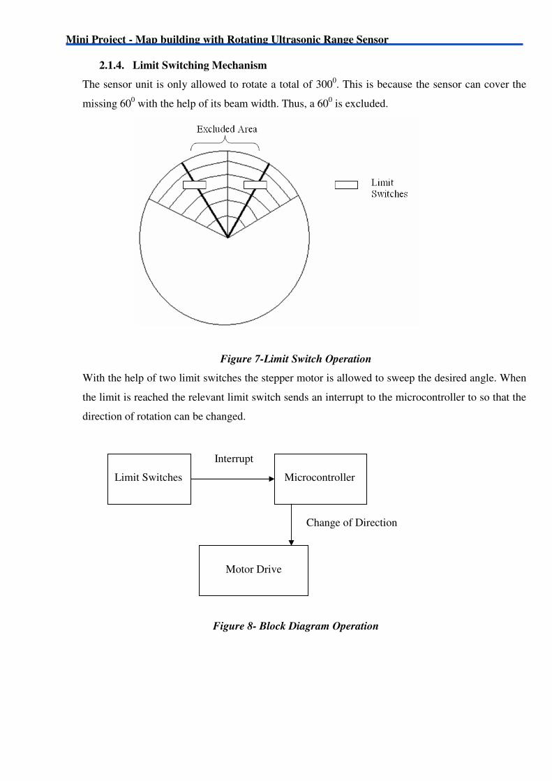
2.1.4. Limit Switching Mechanism
The sensor unit is only allowed to rotate a total of 3000. This is because the sensor can cover the
missing 600 with the help of its beam width. Thus, a 60
0 is excluded.
Figure 7-Limit Switch Operation
With the help of two limit switches the stepper motor is allowed to sweep the desired angle. When
the limit is reached the relevant limit switch sends an interrupt to the microcontroller to so that the
direction of rotation can be changed.
Figure 8- Block Diagram Operation
Limit Switches
Microcontroller
Motor Drive
Interrupt
Change of Direction

Mini Project - Map building with Rotating Ultrasonic Range Sensor
2.1.5. Microcontroller Unit
The microcontroller used for this system is a PIC16F877A by Microchip Corporation. The
microcontroller unit accounts for these events.
a. Stepper Motor Driving
- Speed
- Direction of rotation
b. Ultra sonic Range Sensor Interfacing
- Sensor Triggering
- Obtaining the round trip time for the echo
c. PC interfacing via RS232
- Output the observations to the PC
- Responding to the PC instructions
PORT D of the PIC was used to send control signals to the stepper motor driver system. By
reversing the order of control bits the rotating direction of the motor can be reversed. Also by
driving all bits to zero the motor can be stopped.
A reading from the range sensor for the round trip time is obtained at each step angle that is
each 1.50
step. Four such readings are averaged inside the PIC to obtain a more accurate
reading. The round trip time is in the class of µs.
The PIC performs its operations according to the commands sent by the PC program. For
instance the PC program can either direct the system to function in the global or local mode by
sending a control character using the RS232 serial link between the PC and the hardware sub
system. When the system is switched to local mode the PC program sends the location and
sweep information in addition to the control signal. Apart from this the PC can direct the shaft
to move to the initial position or stop. Above all these the RS232 link is used to feed the PC
with the data obtained from the sonar sensor.

Mini Project - Map building with Rotating Ultrasonic Range Sensor
2.2. MAPPING SOFTWARE
The software was written using Visual C# .NET 2005 and has several functionalities. These are
• Communication with the PIC Micro-controller using serial communication
• Sending the user commands to the Micro-controller in the form of ASCII characters
• Obtaining the delays of the echoes for each angle and keeping the information in an updated
array after converting the delay (ms) into distance (m).
• Updating the display (map) based on the distance information kept on the array.
• Calculate a probability of occupation based on the sensor model (for the Ultrasonic Range
sensor) for each of the positions and use the Bayesian Model to combine the results of the
different readings (Sensor fusion)
2.2.1. Software Functionality

Mini Project - Map building with Rotating Ultrasonic Range Sensor
2.3. PROBABILITY MODEL
2.3.1. Sonar Sensor Model
In this model the Sensors’ range area is divided into three regions based on the delay (i.e. the
alleged distance of the obstacle). The Whole area is divided into a grid (whose no of elements will
decide the resolution of the Mapping model) and each of the squares is assigned a probability based on
its position with relative to the sensor reading.
The probability of occupation will be calculated differently based on which region it occupies.
Region I
( )2
( ) 1 ( )
Occupied
R r
RP Occupied Max
P Empty P Occupied
β α
α
− − +
= ×
= −
Region II
( )2
( ) 1 ( )
R r
RP Empty
P Empty P Occupied
β α
α
− − +
=
= −

Mini Project - Map building with Rotating Ultrasonic Range Sensor
Region III
The model does not assign a probability to this region as no information can be derived from
the sensor after the first echo.
R = Range of the Sonar sensor
r = Distance to the Grid the Grid Element
β = Sonar Beamwidth
α = Angle to Grid Element
MaxOccupied = Highest Possible Probability
2.3.2. Sensor Fusion
The grid which covers the entire possible sweep area is filled as the reading for each angle
comes from the Micro-controller. The overlapping regions can be combined using any of number
methods such as Bayesian, Dempster-Shafer and HIMM (Histogramic In Motion Mapping). Of these
the Bayesian method has been employed to combine the different readings.
2.4. Modes of Operation
There are two modes of Operation available in the software. These are,
� Full scan or Global Mode
This allows the system to scan the entire area (3000) that is limited by the limit
switches. In this mode the area can be entirely viewed (360) using the probability
Model.
� Local Scan Mode
This allows the system to scan a specific area (a limited degrees) if a user needs
to scan a particular segment.

Mini Project - Map building with Rotating Ultrasonic Range Sensor
2.5. GUI
GUI Operation
• Global Mode Operation
To operate in the Global Scan Mode select ‘ ’ and click on the button
Then the sensor shaft will return to the starting position indicated by the arrow and start
scanning for the full range.
• Local Mode Operation
To operate in the Local Scan Mode select ‘ ’. Once this option is selected click
on the button and select the range required to on the map (on the left) and click on the
button.
• Probability Model
In order to activate the probability model click the button.
This can be shown in two methods.
� Color graded: This can be activated by selecting the . This will assign
different colors to the grids based on the probability.
� Monochrome: This is the default mode which will show grid elements with 0.5 or
greater probability as black and others as white.

Mini Project - Map building with Rotating Ultrasonic Range Sensor
3.0 APPENDIX
3.1. ULN2003
• Seven Darlingtons per package output current 500mA per driver (600mA peak)
• Output voltage 50V.
• Integrated suppression diodes for inductive loads outputs can be paralleled for high current.
• TTL/CMOS/PMOS/DTL compatible input pinned opposite outputs to simplify layout.
Description
The ULN2003 is a high voltage, high current Darlington array containing seven open collector
Darlington pairs with common emitters. Each channel rated at 500mA and can withstand peak currents
of 600mA. Suppression diodes are included for inductive load driving and the inputs are pinned
opposite the outputs to simplify board layout.
This versatile device is useful for driving a wide range of loads including solenoids, relays DC motors,
LED displays filament lamps, thermal print heads and high power buffers. The ULN2003A is supplied
in 16 pin plastic DIP packages with a copper lead frame to reduce thermal resistance. This is available
also in small outline package (SO-16) as ULN2003D.
Pin Connection

Mini Project - Map building with Rotating Ultrasonic Range Sensor

Mini Project - Map building with Rotating Ultrasonic Range Sensor
3.2. SRF05 - Ultra-Sonic Range sensor
The SRF05 is designed to increase flexibility, increase range, and to reduce costs still further. The
Range is increased from 3 meters to 4 meters. A new operating mode (tying the mode pin to ground)
allows the SRF05 to use a single pin for both trigger and echo, thereby saving valuable pins on your
controller. When the mode pin is left unconnected, the SRF05 operates with separate trigger and echo
pins, like the SRF04. The SRF05 includes a small delay before the echo pulse to give slower
controllers such as the Basic Stamp and Picaxe time to execute their pulse in commands.
Mode - SRF04 compatible - Separate Trigger and Echo
This mode uses separate trigger and echo pins, and is the simplest mode to use. All code examples for
the SRF04 will work for the SRF05 in this mode. To use this mode, just leave the mode pin
unconnected - the SRF05 has an internal pull up resistor on this pin.

Mini Project - Map building with Rotating Ultrasonic Range Sensor
Figure 2


