
Project Report …downloads.hindawi.com/journals/stni/2010/425658.pdfreactor and nuclear power plant...
18
Hindawi Publishing Corporation Science and Technology of Nuclear Installations Volume 2010, Article ID 425658, 17 pages doi:10.1155/2010/425658 Project Report Role of RELAP/SCDAPSIM in Nuclear Safety C. M. Allison and J. K. Hohorst Innovative Systems Software, LLC, 1284 South Woodruff Avenue, Idaho Falls, ID 83404, USA Correspondence should be addressed to C. M. Allison, [email protected] Received 17 August 2009; Accepted 10 January 2010 Academic Editor: Michel Giot Copyright © 2010 C. M. Allison and J. K. Hohorst. This is an open access article distributed under the Creative Commons Attribution License, which permits unrestricted use, distribution, and reproduction in any medium, provided the original work is properly cited. The RELAP/SCDAPSIM code, designed to predict the behaviour of reactor systems during normal and accident conditions, is being developed as part of the international SCDAP Development and Training Program (SDTP). SDTP consists of nearly 60 organizations in 28 countries supporting the development of technology, software, and training materials for the nuclear industry. The program members and licensed software users include universities, research organizations, regulatory organizations, vendors, and utilities located in Europe, Asia, Latin America, and the United States. Innovative Systems Software (ISS) is the administrator for the program. RELAP/SCDAPSIM is used by program members and licensed users to support a variety of activities. The paper provides a brief review of some of the more important activities including the analysis of research reactors and Nuclear Power Plants, design and analysis of experiments, and training. 1. Introduction The RELAP/SCDAPSIM code, designed to predict the behaviour of reactor systems during normal and accident conditions, is being developed as part of the international SCDAP Development and Training Program (SDTP) [1, 2]. Three main versions of RELAP/SCDAPSIM, as described in Section 2, are currently used by program members and licensed users to support a variety of activities. RELAP/SCDAPSIM/MOD3.2, and MOD3.4 are production versions of the code and are used by licensed users and program members for critical applications such as research reactor and nuclear power plant applications. The most advanced production version, MOD3.4, is also used for general user training and for the design and analysis of severe accident related experiments such as those performed in the Phebus and Quench facilities. In turn, these experiments are used to improve the detailed fuel behaviour and other severe accident-related models in MOD3.4 and MOD4.0. MOD4.0 is currently available only to program members and is used primarily to develop advanced modelling options and to support graduate research programs and training. 2. RELAP/SCDAPSIM RELAP/SCDAPSIM uses the publicly available RELAP/ MOD3.3 [3] and SCDAP/RELAP5/MOD3.2 [4] models developed by the US Nuclear Regulatory Commission in combination with proprietary (a) advanced program- ming and numerical methods, (b) user options, and (c) models developed by ISS and other members of the SDTP. These enhancements allow the code to run faster and more reliably than the original US NRC codes. RELAP/SCDAPSIM/MOD3.2 was the first produc- tion version released under SDTP sponsorship. It was designed to duplicate the modeling options available from the original US NRC versions of RELAP/MOD3.3 and SCDAP/RELAP5/MOD3.2 but run faster and more reliably. This version used standard RELAP5 and SCDAP/RELAP5 input but included enhanced output options such as integrated 3D and time history plotting options. This version also included a number of coding and numer- ical improvements to improve the performance of the code. RELAP/SCDAPSIM/MOD3.4 is the current produc- tion version and is designed specifically for “faster-than- real-time” simulations on typical Windows or LINUX PCs.
Transcript of Project Report …downloads.hindawi.com/journals/stni/2010/425658.pdfreactor and nuclear power plant...

Hindawi Publishing CorporationScience and Technology of Nuclear InstallationsVolume 2010, Article ID 425658, 17 pagesdoi:10.1155/2010/425658
Project Report
Role of RELAP/SCDAPSIM in Nuclear Safety
C. M. Allison and J. K. Hohorst
Innovative Systems Software, LLC, 1284 South Woodruff Avenue, Idaho Falls, ID 83404, USA
Correspondence should be addressed to C. M. Allison, [email protected]
Received 17 August 2009; Accepted 10 January 2010
Academic Editor: Michel Giot
Copyright © 2010 C. M. Allison and J. K. Hohorst. This is an open access article distributed under the Creative CommonsAttribution License, which permits unrestricted use, distribution, and reproduction in any medium, provided the original work isproperly cited.
The RELAP/SCDAPSIM code, designed to predict the behaviour of reactor systems during normal and accident conditions, isbeing developed as part of the international SCDAP Development and Training Program (SDTP). SDTP consists of nearly 60organizations in 28 countries supporting the development of technology, software, and training materials for the nuclear industry.The program members and licensed software users include universities, research organizations, regulatory organizations, vendors,and utilities located in Europe, Asia, Latin America, and the United States. Innovative Systems Software (ISS) is the administratorfor the program. RELAP/SCDAPSIM is used by program members and licensed users to support a variety of activities. The paperprovides a brief review of some of the more important activities including the analysis of research reactors and Nuclear PowerPlants, design and analysis of experiments, and training.
1. Introduction
The RELAP/SCDAPSIM code, designed to predict thebehaviour of reactor systems during normal and accidentconditions, is being developed as part of the internationalSCDAP Development and Training Program (SDTP) [1, 2].Three main versions of RELAP/SCDAPSIM, as describedin Section 2, are currently used by program membersand licensed users to support a variety of activities.RELAP/SCDAPSIM/MOD3.2, and MOD3.4 are productionversions of the code and are used by licensed users andprogram members for critical applications such as researchreactor and nuclear power plant applications. The mostadvanced production version, MOD3.4, is also used forgeneral user training and for the design and analysis of severeaccident related experiments such as those performed in thePhebus and Quench facilities. In turn, these experimentsare used to improve the detailed fuel behaviour and othersevere accident-related models in MOD3.4 and MOD4.0.MOD4.0 is currently available only to program membersand is used primarily to develop advanced modellingoptions and to support graduate research programs andtraining.
2. RELAP/SCDAPSIM
RELAP/SCDAPSIM uses the publicly available RELAP/MOD3.3 [3] and SCDAP/RELAP5/MOD3.2 [4] modelsdeveloped by the US Nuclear Regulatory Commissionin combination with proprietary (a) advanced program-ming and numerical methods, (b) user options, and(c) models developed by ISS and other members ofthe SDTP. These enhancements allow the code to runfaster and more reliably than the original US NRCcodes. RELAP/SCDAPSIM/MOD3.2 was the first produc-tion version released under SDTP sponsorship. It wasdesigned to duplicate the modeling options available fromthe original US NRC versions of RELAP/MOD3.3 andSCDAP/RELAP5/MOD3.2 but run faster and more reliably.This version used standard RELAP5 and SCDAP/RELAP5input but included enhanced output options such asintegrated 3D and time history plotting options. Thisversion also included a number of coding and numer-ical improvements to improve the performance of thecode. RELAP/SCDAPSIM/MOD3.4 is the current produc-tion version and is designed specifically for “faster-than-real-time” simulations on typical Windows or LINUX PCs.

2 Science and Technology of Nuclear Installations
South1 2 3 4 5 6 7 8 9
East
A
B
C
D
E
F
G
H
North
West
Fuel assembly
Control assembly
Flux trap
Solid aluminium
Hollow aluminium
Solid beryllium
Hollow beryllium
Solid lead
Figure 1: SAFARI reactor core configuration.
The designation MOD3.4 is used to indicate that additionalmodeling options have been included relative to the originalUS NRC codes. These modeling options include improvedmodels for a detailed fuel rod, an electrically heated fuelrod simulator, and other SCDAP core components. Othermodeling improvements include new models and correla-tions for air ingression transients and alternative fluids andcladding materials. Continued improvements in the codingand numerics also allow both MOD3.4 and MOD4.0 to run awider variety of transients including low-pressure transientswith the presence of noncondensable gases such as thoseoccurring during mid-loop operations in LWRs, in pool typereactors, or in spent fuel storage facilities.
The most advanced version of the code, RELAP/SCDAPSIM/MOD4.0 [5], is the first version of RELAPor SCDAP/RELAP5 completely rewritten to FORTRAN90/95/2000 standards. This is a significant benefit forthe program members that are using the code for thedevelopment of advanced models and user options such asthe coupling of the code to other analysis packages. Cou-pled 3D reactor kinetics and coupled RELAP/SCDAPSIM-SAMPSON [6] calculations are examples where MOD4.0 isused because of a significant reduction in the code devel-opment effort and expense to link the packages. MOD4.0also includes advanced numerical options such as improvedtime advancement algorithms, improved water propertytables, and improved model coding. As a result the codecan reliably run complex multidimensional problems fasterthan real time on inexpensive personal computers. Plant
simulation and integrated uncertainty analysis are among themost important applications benefiting from the improvedspeed and reliability of MOD4.0. MOD4.0 includes manyenhanced user options to improve the accuracy of thecode or to offer new options for the users. For example,the addition of an alternative material property librarydesigned for Zr-Nb cladding materials is important forVVER and CANDU reactor designs, particularly for severeaccident-related transients. The addition of an advancedwater property formulation is important for many transients,in particular those involving super critical water applica-tions.
3. Review of Representative Applications
RELAP/SCDAPSIM is being used for a variety of appli-cations. As described in Section 3.1, the code is usedfor the analysis of research reactors and nuclear powerplants. The research reactors analysed by the code includeTRIGAs, MTR-plate designs, and other unique designswell as. Nuclear plants analysed include Western designedPWRs and BWRs, Russian designed VVERs and RMBKs,Canadian and Indian designed CANDUs and HWRs, andChinese designed PWRs. The analysis of experiments, asdiscussed in Section 3.2, is also an important applicationof the code, including the design of the experiments, theassessment and development of modelling improvements,and finally for advanced user training. The application of thecode to support the development of improved models andanalytic capabilities is discussed in Section 3.3. Section 3.4presents an overview of the application of the code fortraining.
3.1. Research Reactor and NPP Applications. A combinationof RELAP/SCDAPSIM/MOD3.2 and MOD3.4 is being usedto analyze research reactors. A brief summary of the earlywork by several countries was given in [6]. The researchreactors noted in this paper include (a) the LVR-15 reactorlocated at the Nuclear Research Institute in Rez, CzechRepublic, (b) the CARR reactor being built in Beijing, Chinaby the China Institute of Atomic Energy, and (c) TRIGA reac-tors located at the Atomic Energy Research Establishment inDhaka, Bangladesh, and National Nuclear Energy Agency inBandung Indonesia. LVR-15 is a light-water moderated andcooled pool type reactor with a nominal thermal power of15 MW. The pool operates at atmospheric pressure with anaverage coolant temperature in the core of 320 K. The reactoralso has closed high-pressure/temperature loops suitable fortesting of materials under PWR and BWR conditions. Thereactor core is composed of several fuel assemblies of Al-Ualloy arranged in square concentric tubes. CARR is a tank-in-pool design, cooled and moderated by light water andreflected by heavy water. The rated power is 60 MW. Thecore consists of plate-type fuel assemblies of Al-U alloy. TheIndonesian and Bangladesh TRIGA reactors are pool typereactors with 2 MW and 3 MW thermal power, respectively.The reactor cores are composed of solid U-ZrH fuel rodsarranged in a hexagonal array and are cooled by water in

Science and Technology of Nuclear Installations 3
tmdpvol
tmdpvol
Pipe(3 vols)
Pipe(7 vols)
Pipe(2 vols)
Pipe(3 vols)
Pipe(4 vols)
Pipe(7 vols)
Pipe(2 vols)
Pipe(2 vols)
805
900
899
134
802
116
898
133
132
131
115
113 113
111
109
108
107
803
801
PZRTNK
PZRSRG
PZRSRG
J804
J114
J112
110
trpvlv
mtrvlvV527
mtrvlvV420
402 mtrvlvV546
mtrvlvV507b
chkvlvV517
chkvlvV502
branch
branch
snglvol
pump
CONTMT
BRANCH
COLDLEG1
PZR-OUT
HX-OUT2
HX-OUT
HTEXGER
HOTLEG5
PUMP-OUT
PRI-PUMP
PUMP-IN
tmdpvol
Pipe(7 vols)
snglvol
Pipe(3 vols)
Pipe(2 vols)
Pipe(3 vols)
Pipe(7 vols)
Pipe(9 vols)
901
902
139 401
405
903
136
135
137
904
135
137
401
406449
460
406
407
407
405
460
139
100
101
102
104
100
101
102
105
J106
905
trpvlv
trpvlv
906 trpvlv
mtrvlvV507a
mtrvlvV543
branch
branch
branch
snglvol
snglvol
INPLHXIN
CONTMT
tmdpvol
CONTMT
907tmdpvol
CONTMT
BRANCH
branchBRANCH
COLDLEG3
VESINLET
COLDLEG
Core
END-TEE
ANTI-TK
ENDPIPE
HOTLEG1
HOTLEG2
HOTLEG3
INPLHX
Figure 2: MURR RELAP/SCDAPSIM nodalization of the MURR pressurized primary cooling system.
Tmdpvol
Annulus (6 vols)
Pipe(7 vols)
Pipe(1 vol)
Pipe(1 vol)
Annulus (1 vol)
Pipe(6 vols)
702501
501
502
- 50
5
524
- 52
7
GA
MM
A H
EA
T
703
720
700
705
710
715
708
725 735
J704
Branch
BranchPump
POOL-SUP
POOLPUMP
PLTPPUMP
PO
OL
HX
POOL
V547GRAPHITE
LOPLPLEN
CNTBLDGPISLAND
PRESSVOL
Figure 3: RELAP/SCDAPSIM nodalization of the MURR bulk reactor pool and pool coolant loop.
either forced or natural circulation, depending upon theconditions.
More recently, the analysis of two additional reactor typeshave been reported in [7–9]. The first is for the SAFARI-1research reactor located in South Africa [7, 8]. The secondis the University of Missouri Research Reactor located inthe United States [9]. The SAFARI-1 research reactor is a
tank-in-pool type reactor operated at a nominal core powerof 20MW. The core is cooled and moderated by forcedcirculation of light water. The reactor core can be operatedin a variety of configurations from 24 to 32 fuel assemblies.Figure 1 shows an example of one such configuration. Thefuel is U-Si-Al plate-type fuel elements. MURR is a 10 MWpool type reactor design with a pressurized primary coolant
4 Science and Technology of Nuclear Installations
705
(6)
575
705
(5)
505
705
(4)
504
705
(3)
503
705
(2)
502
502
(4)
676
502
(3)
651
502
(2)
626
502
(1)
601
503
(4)
677
503
(3)
652
503
(2)
627
503
(1)
602
504
(4)
678
504
(3)
653
504
(2)
628
504
(1)
505
(4)
505
(3)
505
(2)
505
(1)
506
(4)
506
(3)
506
(2)
506
(1)
507
(4)
507
(3)
507
(2)
507
(1)
508
(4)
508
(3)
508
(2)
508
(1)
509
(4)
509
(3)
509
(2)
509
(1)
510
(4)
510
(3)
510
(2)
510
(1)
511
(4)
511
(3)
511
(2)
511
(1)
512
(4)
512
(3)
512
(2)
512
(1)
513
(4)
513
(3)
513
(2)
513
(1)
514
(4)
514
(3)
514
(2)
514
(1)
515
(4)
515
(3)
515
(2)
515
(1)
516
(4)
516
(3)
516
(2)
516
(1)
517
(4)
517
(3)
517
(2)
517
(1)
518
(4)
518
(3)
518
(2)
518
(1)
519
(4)
519
(3)
519
(2)
519
(1)
520
(4)
520
(3)
520
(2)
520
(1)
521
(4)
521
(3)
521
(2)
521
(1)
522
(4)
522
(3)
522
(2)
522
(1)
523
(4)
523
(3)
523
(2)
523
(1)
524
(4)
524
(3)
524
(2)
524
(1)
525
(4)
525
(3)
525
(2)
525
(1)
526
(4)
526
(3)
526
(2)
526
(1)
715
(5)
715
(4)
715
(3)
715
(2)
603
679
654
629
604
680
655
630
605
681
656
631
606
682
657
632
607
683
658
633
608
684
659
634
609
685
660
635
610
686
661
636
611
687
662
637
612
688
663
638
613
689
664
639
614
690
665
640
615
691
666
641
616
692
667
642
617
693
668
643
618
694
669
644
619
695
670
645
620
696
671
646
621
697
672
647
622
698
673
648
623
699
674
649
624
527
526
525
525
715
(1)
501
715
(6)
575
705
(1)
501
Upper plenum
Lower plenum
(501)
(575)
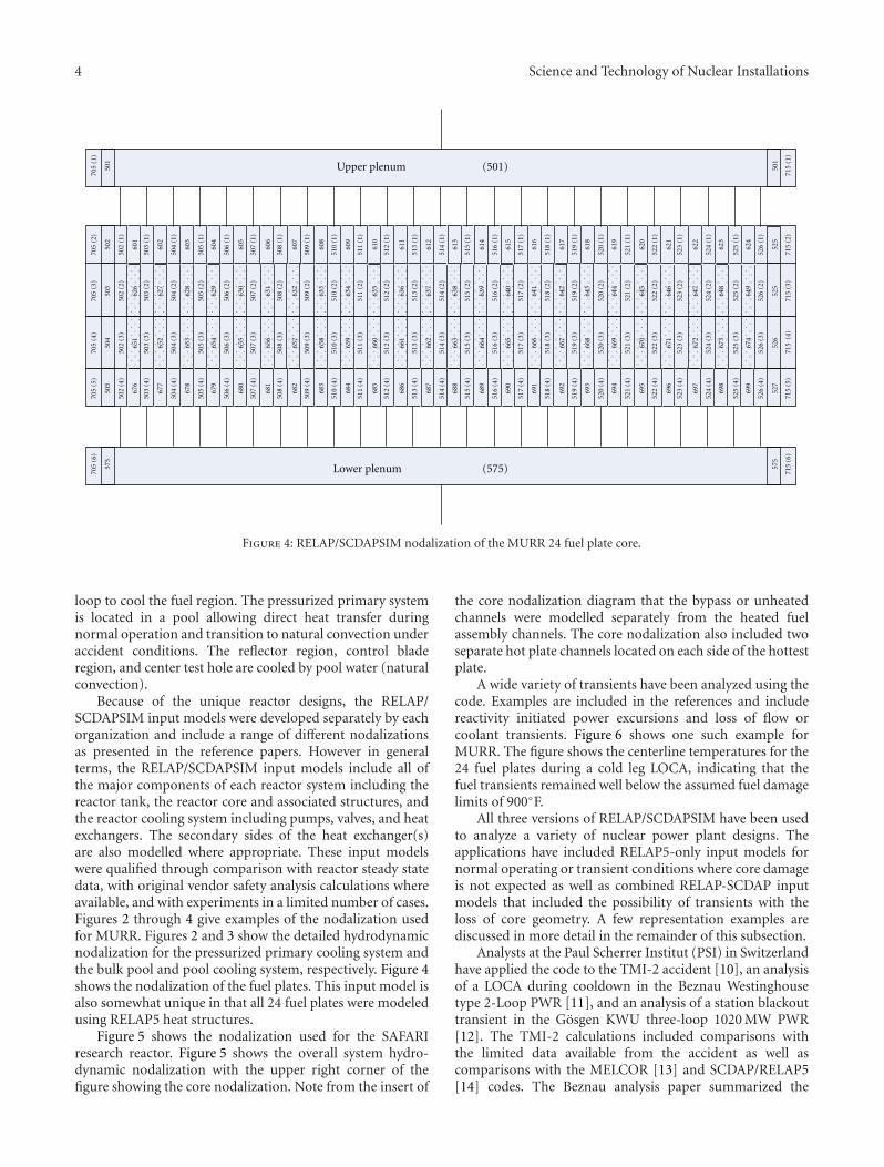
Figure 4: RELAP/SCDAPSIM nodalization of the MURR 24 fuel plate core.
loop to cool the fuel region. The pressurized primary systemis located in a pool allowing direct heat transfer duringnormal operation and transition to natural convection underaccident conditions. The reflector region, control bladeregion, and center test hole are cooled by pool water (naturalconvection).
Because of the unique reactor designs, the RELAP/SCDAPSIM input models were developed separately by eachorganization and include a range of different nodalizationsas presented in the reference papers. However in generalterms, the RELAP/SCDAPSIM input models include all ofthe major components of each reactor system including thereactor tank, the reactor core and associated structures, andthe reactor cooling system including pumps, valves, and heatexchangers. The secondary sides of the heat exchanger(s)are also modelled where appropriate. These input modelswere qualified through comparison with reactor steady statedata, with original vendor safety analysis calculations whereavailable, and with experiments in a limited number of cases.Figures 2 through 4 give examples of the nodalization usedfor MURR. Figures 2 and 3 show the detailed hydrodynamicnodalization for the pressurized primary cooling system andthe bulk pool and pool cooling system, respectively. Figure 4shows the nodalization of the fuel plates. This input model isalso somewhat unique in that all 24 fuel plates were modeledusing RELAP5 heat structures.
Figure 5 shows the nodalization used for the SAFARIresearch reactor. Figure 5 shows the overall system hydro-dynamic nodalization with the upper right corner of thefigure showing the core nodalization. Note from the insert of
the core nodalization diagram that the bypass or unheatedchannels were modelled separately from the heated fuelassembly channels. The core nodalization also included twoseparate hot plate channels located on each side of the hottestplate.
A wide variety of transients have been analyzed using thecode. Examples are included in the references and includereactivity initiated power excursions and loss of flow orcoolant transients. Figure 6 shows one such example forMURR. The figure shows the centerline temperatures for the24 fuel plates during a cold leg LOCA, indicating that thefuel transients remained well below the assumed fuel damagelimits of 900◦F.
All three versions of RELAP/SCDAPSIM have been usedto analyze a variety of nuclear power plant designs. Theapplications have included RELAP5-only input models fornormal operating or transient conditions where core damageis not expected as well as combined RELAP-SCDAP inputmodels that included the possibility of transients with theloss of core geometry. A few representation examples arediscussed in more detail in the remainder of this subsection.
Analysts at the Paul Scherrer Institut (PSI) in Switzerlandhave applied the code to the TMI-2 accident [10], an analysisof a LOCA during cooldown in the Beznau Westinghousetype 2-Loop PWR [11], and an analysis of a station blackouttransient in the Gosgen KWU three-loop 1020 MW PWR[12]. The TMI-2 calculations included comparisons withthe limited data available from the accident as well ascomparisons with the MELCOR [13] and SCDAP/RELAP5[14] codes. The Beznau analysis paper summarized the

Science and Technology of Nuclear Installations 5
Quick acting valve
Quick acting valve
On
e th
inbl
e
Five
th
inbl
es
For details of core model see inset at right
Reactor vessel upper tank
Reactor vessel lower tank
Blanketregion
Hartford loop
Poolconnection
Outletpressuresensor
Reactor inlet temperatureand pressure sensors
T T
T
P
P
Un
fuel
led
chan
nel
s
Core model detail
Balance offuelled
channels
Hot
ele
men
t ch
ann
el(m
inu
s h
ot p
late
s)
Hot platechannels
Hot plates
Hot spot
Sensor for inlet temperature control
Heat exchanger
Heat exchanger
Heat exchanger
Loopisolationvalveandstrainer
Demin and large facility
take - off
Temperature control bypass loop
Shutdown/emergency pump(s)
Primary pumps
Deminreturn
Decay tank
Floworifice
Large facility returnRelaps/safari-1 reactor
Thermal- hydraulic model version 3.0
Junction ( leak flow)
Hydrodynamic volume
Time dependent junction
Time dependent volume
Pump
Valve
Check valve
Heat structure with power source
Passive heat structure
(REV 04, JUL 1996, A.J.D’Arcv)
Outlettemperaturesensors
538 535536 003002
0041
5
4
4
3
3
2
2
1
1
3
2
19 8 7 6 5 4 3 2 1
1 2 3 4 5 6 7 8 9
1 2 3 4 5 6 7 8 9
10
10
10
19 18 17 16 15 14 13 12 11 10
1
1
2 3 4 5 6
6
7 8
2
1
2
12
11
2 2
006
060
514
040
061
062
101
513
102
104
512516
511
107
108 524
525
112111
110100
140
130 143
120
602
604
122
132
142
133123
146
160
022
026
2
1 1 1
2 2
347
306
006
011031 015 021 025
016012032
033 013 017 023 027
028060
061 029
062
395 393394
348 340
390391
350
392
1 2 3 4 5 6 7 8 9
1 2 3 4 5 6 7 8 9
19 18 17 16 15 14 13 12 11
250
292
10
101 2 3 4 5 6 7 8 9
1 2 3 4 5 6 7 8 9
19 18 17 16 15 14 13 12 11
150
192
296295 293
294
240249
290291
196
194195 193
148149
190155
156 158157
152153
151
159
252 253
353352
161
522
521
351
251
191
247147
105
517
526527
106
163162
103
164
501500
515
105
530 532531
043
533
047
041045 005
#1
#2
#3
Figure 5: RELAP/SCDAPSIM nodalization of the SAFARI cooling system.
Tem
per
atu
re(F
)
140150160170180190200210220230240250260270280290300310320
Time (seconds)
0 2 4 6 8 10 12 14 16 18 20
Figure 6: Example of RELAP/SCDAPSIM-calculated fuel platecenterline temperatures for the 24 fuel plates in MURR for a coldleg large break transient.
results of the analyses of postulated LOCAs in the Beznau(KKB) PWR, occurring during hot (HS) and intermediate
(IS) shutdown with emphasis on large break LOCAs duringhot shutdown. The large break LOCA during HS posed thegreatest challenge to the plant safety systems. The analysisof the station blackout transient in the Gosgen NuclearPlant focused on the impact of a potential failure of thedepressurization system. In particular, the analysis focusedon the timing of the heatup and failure of the RCS pipingrelative to the relocation of melt into the lower plenum andfailure of the lower head. MELCOR, RELAP/SCDAPSIM,and SCDAP/RELAP5 were also used in both Beznau andGosgen analyses.
The TMI-2 RELAP/SCDAPSIM and SCDAP/RELAP5nodalization, as shown in Figure 7, used a 2-dimensionalrepresentation of the core region with a detailed SCDAPcomponents being used to describe the behavior of thefuel rods and other core structures within each of the fiverepresentative flow channels in the core. The transitionfrom the initial intact core geometry to a damaged state isautomatically handled by the SCDAP models including theinitial failure of the control rods, liquefaction and relocationof the metallic U-O-Zr fuel rod material, formation and

6 Science and Technology of Nuclear Installations
435
431
430440
452
450
402Afw
Mainfeedwater
405
410
225Loop A
HPI/makeup
642
641
110
115
121122123124125126135
145 143 141
151
161
171
300
360MCPs
370330
335 375 365355
350
343
344
510
505 Mainfeedwater
Afw
630
632
640 650
531
632
616
OTSG
315
602
HPI/makeup
Loop B325
173
163166
175
180
Reactor pressure vessel
Pressurizer
Surge-line
176100
101 166
153155156102
286 276 266
260270280
700
200
250
MCPs
255
300 235Letdown
415
215210 710
PORV
720
730
711
712
740
206
OTSG30
0
210
300
230
100
300
300
500
520
245
Figure 7: TMI-2 nodalization used for RELAP/SDAPSIM and SCDAP/RELAP5.
Pre
ssu
re(P
a)
4e+06
6e+06
8e+06
1e+07
1.2e+07
1.4e+07
1.6e+07
1.8e+07
Time (s)
0 5000 10000 15000 20000
S/Sim SR4S/Sim SR6S/Sim SR5S/Sim SR3
S/R5 SR4S/R5 SR6TMI-2 NSAC-1
Figure 8: Example of RELAP/SDAPSIM and SCDAP/RELAP5TMI-2-calculated results for system pressure for a range of metallicfuel rod material relocation modeling parameters.
growth of a ceramic [U-Zr]-O2 molten pool, and relocationof the molten ceramic into the lower plenum. Figure 8shows one of the set of representative calculations presentedin the paper. The figure shows the variation in predictedsystem pressure for a range of modeling parameters for therelocation of the metallic U-O-Zr fuel rod material for bothRELAP-based codes. It was noted in the paper that both
RELAP-based codes correctly calculated an in-core moltenpool, of which two RELAP/SCDAPSIM cases predictedrelocation to the lower head (via the bypass, as observed),while only one MELCOR case did so. It was further notedthat the RELAP-based codes correctly calculated that lowerhead failure did not occur.
The Beznau RELAP/SCDAPSIM and SCDAP/RELAP5nodalization, as shown in Figure 9, also used a 2-dimensionalrepresentation of the core region with detailed SCDAPcomponents used to describe the behavior of the fuelrods and other core structures within each of the fiverepresentative flow channels in the core. Figure 10 showsone of the set of representative calculations presented inthe paper. The figure shows the peak cladding temperaturescalculated by RELAP/SCDAPSIM and SCDAP/RELAP5 fordifferent assumptions regarding the activation of the SafetyInjection pumps including the number of pumps and delaysin the actuation of the pumps. The paper concludes that allthree codes predict that in the limiting large break case thecore is readily quenched without damage, by the nominaloperation of the system injection system. However, it wasnoted that the more mechanistic RELAP-based calculationsdemonstrated that a larger margin existed (relative to thatpredicted by MELCOR) with recovery being possible even ifonly one pump operates after some delay.
The RELAP/SCDAPSIM and SCDAP/RELAP5 nodaliza-tion used for the Gosgen analysis also included a detailedcore nodalization as described previously. However, thecalculations also looked at the effect of hot leg naturecirculation using a split hot leg model as shown in Figure 11.The split channel model allows the hotter vapor to move

Science and Technology of Nuclear Installations 7
290SRV A
SRV D
N*2/V
289
288410
404
Containment
Main steam systemisolation and secondary relief valves
284
Main steam line
282
280
278
Steamdome
SeparatersteamgeneratorA
Cross-overleg
Drier
270
272
1
2
3
4
Downcomer
274
InputOutput 208212SGplena
1
2
214
760
Accumulator A
750
Distributor
701 725
JSI 1-A, B
731Injection lines
229
containment
228
224
737
734
324 320 318
304302300 Hot leg B
21
316
306
308 312
376374
372388
383
385
370 378
380
382
384
390
398
396
SteamgeneratorB
310
2
1
2
3
41
2
3
4
5
1
ReactorcoolantpumpB
1
2 314
345
6
Cold leg B
770
748
780
Accumulator B
Distributor
745702
JSI 1-D
Time-dependent volumes are indicated in italics
322
200202
2 1
222220
Surge line
240Reactorvessel
Upper plenum
Core
Lower plenum
Emergency core cooling system
746
ReactorcoolantpumpA
21
1
2 3 4 5 6T
Hot leg A204206
218216
Cold leg A
6
53 4
Pressurizer
242276
210
5
4
3
2
11
2
3
4
5
6
T
Vent valve
402
Vent line
SteamA,B,C
Containment
A, B, C
250,1, 2
Relieflines295
Main
293
288
Emergency
Auditory
Feedwater
Figure 9: Beznau nodalization used for RELAP/SDAPSIM and SCDAP/RELAP5.
Tem
per
atu
re(K
)
300400
500600
700
800
9001000
11001200
1300
1400
15001600
1700
1800
Time (s)
−200 0 200 400 600 800 1000 1200 1400 1600 1800
SR5, JS-ID only, single-sided oxidationSsim, JS-ID only, single-sided oxidationSR5, JS-IA, to lower plenumSsim, JS-IA, to lower plenum
SR5, JS-IA onlySsim, JS-IA onlySR5, JS-ID onlySsim, JS-ID only
Figure 10: Example of RELAP/SCDAPSIM and SCDAP/RELAP5Beznau-calculated results for peak cladding temperature for a rangeof safety injection assumptions.
from the vessel to the steam generators along the top ofthe hot leg and cooler vapor to return along the bottom ofthe hot leg. The influence of the split hot leg input modelrelative to a single channel hot leg (which does not allowcountercurrent flow of the vapor within the hot leg) is shownin Figure 12. As shown in the figure the split hot leg modelpredicted a more gradual heatup of the core but both singlechannel and split channel models still predict rupture of thesurge line or hot leg piping before any molten core materialrelocates into the lower head.
The Politehnica University, Institute for NuclearResearch, and National Commission for Nuclear ActivitiesControl in Romania have used RELAP/SCDAPSIM/MOD3.4for a variety of analyses of CANDU reactor designs. Thework in [13] presents the analysis of a reactor inlet headerbreak, looking at (a) the size of the break, (b) the chokedflow model employed, (c) the emergency core cooling (ECC)performance, and (d) the core nodalization. The resultswere compared with the original safety analysis results.The work in [14] presents the analysis of the influence ofthe header manifold modeling for an inlet header breakin a CANDU 6. The paper looked at a 35% inlet headerbreak which was expected to produce the highest peak fuelcladding temperatures among all postulated break sizes.The work in [15] presents the analysis of a reactor outlet

8 Science and Technology of Nuclear Installations
190−4
−3
−2−1
182−
183−
184−2−1
185−2−1
177
173
171
179
174
172
178
176
170
CenterIntermediate
Outer
core channels
Bypass
Downcomerannulus
Hot legs 2, 3
Sprayline
Reliefvalves
540
530−7
−6
−5−4
−3
−2
−1
520
510
500−6−5−4−3 −2
−1
203−1 −2
201−1 −3
208
206
213−1 −2 −3 −4
211−1 −2 −3 −4
Intermediateleg
216217218 225
−1
−2
−3
−4
−5
−1
−2
−3
−4
−5
−10
−9
−8
−7
−6
−10
−9
−8
−7
−6
221
223
Locations of creep rupture calculation
Figure 11: Gosgen split hot leg nodalization used for RELAP/SDAPSIM and SCDAP/RELAP5.
Cor
em
axim
um
surf
ace
tem
pera
ture
(K)
500
1000
1500
2000
2500
3000
3500
Time (s)
0 2000 4000 6000 8000 10000 12000 14000 16000
bgmct-0 Ssim single HL/SG (kkg-12)bgmct-0 SR5 single HL/SG (kkg-12)bgmct-0 Ssim split HL/SG (kkg-15)bgmct-0 SR5 split HL/SG (kkg-15)
Figure 12:Example of RELAP/SCDAPSIM and RELAP/SCDAPSIM-calculated results for peak core temperature for single and split hotleg model.
header break in a CANDU-6. The paper focused on a 100%reactor outlet header break which had the highest potentialfor fuel failure and release of radioactivity. The paper alsocompared the results to earlier calculations performed using
the CATHENA code [16]. The work in [17] presents ananalysis of the late phase of a severe accident in CANDU6 where bed of dry solid debris or a molten pool of corematerial had already formed at the bottom of the calandriavessel and was externally cooled by shield-tank water. Thestudy used the SCDAP COUPLE module and includedcomparisons with earlier results performed using the ISAAC[18] and MAAP4-CANDU [19] codes.
The general system thermal hydraulic nodalization forthe CANDU system thermal hydraulic analysis analyses [13–15] is shown in Figure 13. Portions of this nodalizationwere varied somewhat depending on the analyses beingperformed. Figure 14 shows an example of the portion ofthe nodalization that was used in [14] for the study ofthe influence of the inlet header model. Figure 15 showsan example of some of the results from the inlet headerbreak model study. In the figure, the reference curve is theresults from a single average channel circuit model usinga single manifold volume and Cases 1, 2, and 3 representthe break location in the multiple inlet manifold volumes incombination with multiple core channels. The curves shownin the figures are the maximum cladding temperatures in fuelbundles contained within the multiple flow channels.
Figure 16 shows the basic problem analyzed for the latephase of a severe accident in a CANDU-6 where a debrisbed is present in the bottom of the calandria vessel alongwith the RELAP5, SCDAP, and COUPLE nodalization usedin the analysis. The RELAP5 thermal hydraulic volumes on

Science and Technology of Nuclear Installations 9
Interconnect
SG1
PMP1
PMP3
ECC
IH2
IF
OF
ECCOH1
IP OP
SG3
ECC
IH6
IF
OF
ECC
Steam generatorInlet feederOutlet feederSG inlet plenumSG outlet plenum
PumpInlet end fittingOutlet end fittingInlet headerOutlet header
Emergency core cooling injection pointPressurizerDegaser - condenserLoop isolation valveHeat transport relief valve
OH5
IP OP
Feed Bleed
IEF
Loop 1
Loop 2
Core pass 1
Core pass 2
Core pass 4
Core pass 3
OEF
OEF
OEF
IEF
SG2
PMP2
PMP4
ECC
IH4
IF OF
ECC
HTRV
LIV
HTRVLIV
PZRDCTNK
OH3
IPOP
SG4
ECC
IH8BK
IF OF
ECC
OH7
IPOP
PMP
HTRVLIV
SG
IH
IFOF
ECC
DCPZR
OH
IEF
IPOP
IEF
OEF
OEF
IEF
Interconnect
Figure 13: RELAP5 thermal hydraulic nodalization for CANDU-6.
From PMP
#1 #2#3IH8
Channel#5
Channel#4Channel#3Channel#2
Channel#1
OH5
To SG
Break location
Figure 14: RELAP5 thermal hydraulic nodalization of manifold headers for CANDU-6 Inlet manifold break analysis.
the right of the figure represent the pool on the outside ofthe calandria vessel. The RELAP5 and SCDAP volumes aboveand within the COUPLE mesh provide initial and boundaryconditions for the debris bed and calandria vessel wall. (Thepaper also included a more detailed RELAP5 nodalization ofthe outer pool at the elevations associated with the debrisbed. The more detailed nodalization resulted in significantlylower pool containment pressures upon vessel failure due tothe more accurate representation of the external cooling ofthe calandria vessel.)
The papers indicated that RELAP/SCDAPSIM calcula-tions gave comparable results to the CANDU-specific codes,CATHENA for system thermal hydraulics, and ISAAC andMAAP-CANDU for severe accidents. For system thermalhydraulic analysis, RELAP/SCDAPSIM, when using similarinput models, provided similar trends as compared to theoriginal safety analysis reports or comparable CATHENAcalculations. However, the results were sensitive to the levelof detail used in the nodalization; specifically the moredetailed nodalization possible using RELAP/SCDAPSIM had

10 Science and Technology of Nuclear Installations
Tem
per
atu
re(K
)
500
700
900
1100
1300
1500
Time (s)
0 10 20 30 40 50 60 70 80 90 100
Reference modelCase 1 channel 4
Case 2 channel 5Case 3 channel 3
Figure 15: Maximum fuel bundle cladding temperatures for a CANDU-6 Inlet manifold break analysis for different break locations.
All heat toshield waterby conduction,radiation andfree convection
Terminaldebris bedon CV bottom
(a)
TDV
750-12
750-11
750-10
750-09
750-08
750-07
750-06
750-05
750-04
750-03
750-02
750-01
1 23
45
67
89101112
999-03
999-04
999-05
TDV
RV
(b)
Figure 16: RELAP, SCDAP, and COUPLE module nodalization and conceptual sketch for CANDU-6 calandria vessel analysis.
a noticeable impact on the results for the inlet headermanifold [14], the fuel channels (simulating the effects ofhorizontally stratified flow in the channels) [13], and theouter pool (exterior to the vessel calandria) [17].
RELAP/SCDAPSIM has also been used to analyze VVERreactor designs although the calculations to date have beenproprietary and have not been published in the open
literature. Figures 17 and 18 show a nonproprietary, butrepresentative, input model for a VVER-1000. This repre-sentative VVER-1000 input model and associated detailedinput model engineering handbook was provided by RiskEngineering in Bulgaria [20] as an in-kind contributionfor use in SDTP-sponsored VVER training activities. Thenodalization of the basic components of the reactor (vessel

Science and Technology of Nuclear Installations 11
99
95 90 93
88 84
85 80
75-2
75-1
72
7170-2
70-1
60
65-5
65-4
65-3
65-2
65-1
77-2
77-1
15
10-1
10-2
10-3
10-4
10-5
10-6
10-7
10-8
10-9
10-10
10-11
50 55
30 3545
25
20
108
208
308
408
105
205
305
405
100
200
300
400
142
242
342
442
Figure 17: Representative vessel input nodalization for VVER-1000 for transients not including the possibility of loss of core geometry.
and internals) is presented in Figure 17 and includes twochannels in the core, the hot and peripheral channels.This basic vessel nodalization would be replaced by amore detailed multidimensional model comparable to thatused for the PWR calculations described previously forgeneral applications where core damage transients mightbe considered. Four separate main circulation loops withtheir corresponding main coolant pumps and cold and hotcirculation pipelines are also included in the representativeinput model as shown in Figure 17.
Analysts at the Lithuanian Energy Institute (LEI) havepublished a number of papers describing their use ofRELAP/SCDAPSIM/MOD3.2 for the analysis of RBMKs.
Recent references are cited as [21–23]. LEI also providednonproprietary, but representative, input models and asso-ciated engineering handbooks for use in SDTP-sponsoredtraining activities. Figure 19 shows the nodalization diagramused for the representative RBMK RCS input model.
All three versions of RELAP/SCDAPSIM have been usedto analyze BWRs although few results have been publishedin the open literature. The work in [24] describes someof the activities related to the use of the code for plantsimulation and training for the Laguna Verde plants inMexico. Figure 20 shows a representative input model, devel-oped by the Nacional de Seguridad Nuclear y Salvaguardias(CNSNS), the Mexican regulatory authority, for the analysis

12 Science and Technology of Nuclear Installations
x = 1, 2, 3, 4y = 1, 2, 3, 4z = 6, 7, 8, 9
Figure 18: Representative loop input nodalization for VVER-1000.
SDV-A MSVI-III
Feed-water
SDV-D
To turbinesand SDV-C
SDV-A MSVI-III
Feed-water
SDV-D
Reactor
FromECCS
FromECCS
1
2
3
4
5
6
7 8
9 10
11
12
1314
15
16
18
17
Figure 19: Representative RCS nodalization for RBMK.
of the Laguna Verde plants. This model is also used tosupport SDTP-sponsored BWR-specific training activities.See Section 3.4 and [24] for more information on theseactivities in Mexico.
3.2. Experimental Analysis. RELAP/SCDAPSIM/MOD3.4has been used by a number of organizations to help design
experiments, to assess thermal hydraulic and severe accidentmodels, and to support advanced user training. In recentyears, the application of the code to experimental analyseshave focused on European experimental programs includingthe German Quench experiments [25–29], French PhebusFPT experiments [30–33], and most recently RussianPARAMETER experiments [34].

Science and Technology of Nuclear Installations 13
420
410
400
390
380
414416
417
430
415
425
435
414
415
425
435
170150
151
260
417
416
370 320 321
325324
322
326
323445
251
245
261
271
246
231
221211201
110281486
111292
293
294
304
300 301
305
302
306
303
465291
350
340 290
475
460
455
360
475
460
455260
270
250
236
235230
220210 200
290485
280
458
Figure 20: Representative RCS nodalization for BWRs.
The most detailed of the calculations have been involvedin the design of new experiments. For example, as describedin detail in [26], the design of new experiments requiresthe development of complex input models to describe theunique features of each experiment and in many cases thedevelopment of specialized new models to treat features ofthe experiments not previously included in the code. In thisexample, the analysts from PSI and experimentalists fromForschungszentrum Karlsruhe (FzK) describe their use ofRELAP/SCDAPSIM/MOD3.4 in conjunction with MELCORand a special FzK-developed version of SCDAP/RELAP5 [35]to design and analyze three different experiments in thequench facility, Quench-10, Quench 11, and Quench 12.Quench 10 was a unique experiment in that it was the firstintegral test to look at the influence of air ingression onbundle heating and reflood. The design and analysis of thisexperiment required PSI to develop and incorporate specialSCDAP models to treat the oxidation of Zircaloy in air/steammixtures. The experimentalist also ran special small separateeffects experiments to help develop the correlations that werethen used in these new models. Quench 11 was a unique testfor the Quench facility in that the test started with the bundlefull of water and then the heat up transient was initiated bythe boil-down of the water. (Previous Quench experimentsused a mixture of steam and argon during the heat up of thebundle prior to reflood.) Although, in this case, it was notnecessary to modify any of the RELAP or SCDAP models, themodeling of the auxiliary heaters, added to the lower plenumof the experimental test train to provide realistic boildown
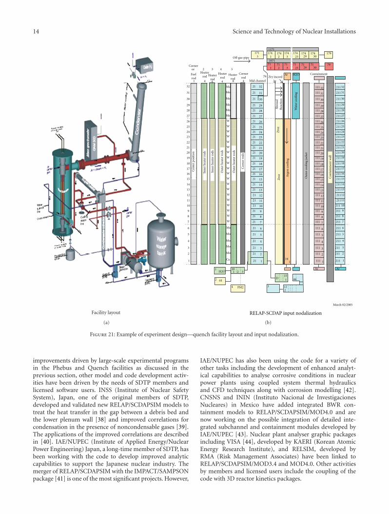
rates, proved to difficult because of relatively large heat lossesin the lower plenum region. QUENCH-12 was unique inthat it was designed to determine the influence of a VVERbundle configuration and cladding on heat-up, oxidation,and quench response. Previous Quench experiments usedPWR or BWR configurations and cladding materials. TheQuench 12 bundle was significantly modified with changesto cladding material (Zr/1%Nb instead of Zry-4), electricalheating, and geometry. Oxidation correlations for Zr/1%Nbin steam were introduced into SCDAP to support the designand analysis of this experiment. Figure 21 shows a schematicof the Quench facility along with the RELAP/SCDAPSIMnodalization diagram.
The analyses of the German Quench and French Phebusexperiments have also played a pivotal role in the assessmentof RELAP5/SCDAPSIM, the development of new improvedmodels as discussed in Section 3.3, and in advanced usertraining as discussed in Section 3.4. The works in [28, 29, 31–33] are examples of the analysis of these experiments to assessthe accuracy of the code and to identify areas where themodels could be improved. The works in [36, 37] describethe use of these experiments to support advanced usertraining.
3.3. Development of Improved Models and Analytic Capa-bilities. The development of improved models and ana-lytic capabilities is also an important part of the overallSDTP cooperative activities. In addition to the modelling
14 Science and Technology of Nuclear Installations
Facility layout
(a)
Cornerrod
Mid channel
Heaterrod
Heaterrod
Heaterrod
Heaterrod
Fuel rod
Corneror 2
1 1
2
3
4
5
6
7
8
9
10
11
12
13
14
15
16
17
18
19
20
21
23
24
25
26
22
27
29
30
31
32
28
1
2
3
4
5
6
7
8
9
10
11
12
13
14
15
16
17
18
19
20
21
23
24
25
26
22
27
29
30
31
32
28
W
W
W
W
W
W
W
W
W
W
W
W
W
W
W
W
W
W
W
W
Mo
Mo
Mo
Mo
Mo
Mo
Cu
Mo
Mo
Mo
Mo
Mo
2114
151 44D
101 2 3
1H2O
2 44
4 FM2 3 122
March 02/2005
ArAr
21
21
21
21
21
21
21
21
21
21
21
21
21
21
21
21
21
21
21
21
21
21
21
21
21
21
21
21
21
21
21
111
111
111
111
111
111
111
111
111
111
111
111
111
111
111
111
111
111
111
111
111
111
111
111
111
111
111
111
111
111
111
111
211
211
211
211
211
211
211
211
211
211
211
211
211
211
211
211
211
211
211
211
211
211
211
211
211
211
211
211
211
211
211
211
1
2
3
4
5
6
7
8
9
10
11
12
13
14
15
16
17
18
19
20
21
23
24
25
26
22
27
29
30
31
32
28
1
2
3
4
5
6
7
8
9
10
11
12
13
14
15
16
17
18
19
20
21
23
24
25
26
22
27
29
30
31
32
28
3 4 5
79
41 4 4 8 4
1 2 3 23 29 3079
1791171
1071717171717171
1 2 3 23 29 30174174174174174174
3171
Cen
ter
pos
itio
n
Inn
er h
eate
r ro
ds
Inn
er h
eate
r ro
ds
Ou
ter
hea
ter
rods
Cor
ner
rod
s
Arg
on c
oolin
g
Wat
er c
oolin
g
Ou
ter
cool
ing
jack
et
Con
tain
men
t w
all
Ou
ter
hea
ter
rods
Ar H2O
Off-gas-pipe
Zry incordContainment
Zro
zSh
rou
dR
eact
ion
Zro
z
RELAP-SCDAP input nodalization
(b)
Figure 21: Example of experiment design—quench facility layout and input nodalization.
improvements driven by large-scale experimental programsin the Phebus and Quench facilities as discussed in theprevious section, other model and code development activ-ities have been driven by the needs of SDTP members andlicensed software users. INSS (Institute of Nuclear SafetySystem), Japan, one of the original members of SDTP,developed and validated new RELAP/SCDAPSIM models totreat the heat transfer in the gap between a debris bed andthe lower plenum wall [38] and improved correlations forcondensation in the presence of noncondensable gases [39].The applications of the improved correlations are describedin [40]. IAE/NUPEC (Institute of Applied Energy/NuclearPower Engineering) Japan, a long-time member of SDTP, hasbeen working with the code to develop improved analyticcapabilities to support the Japanese nuclear industry. Themerger of RELAP/SCDAPSIM with the IMPACT/SAMPSONpackage [41] is one of the most significant projects. However,
IAE/NUPEC has also been using the code for a variety ofother tasks including the development of enhanced analyt-ical capabilities to analyse corrosive conditions in nuclearpower plants using coupled system thermal hydraulicsand CFD techniques along with corrosion modelling [42].CNSNS and ININ (Instituto Nacional de InvestigacionesNucleares) in Mexico have added integrated BWR con-tainment models to RELAP/SCDAPSIM/MOD4.0 and arenow working on the possible integration of detailed inte-grated subchannel and containment modules developed byIAE/NUPEC [43]. Nuclear plant analyser graphic packagesincluding VISA [44], developed by KAERI (Korean AtomicEnergy Research Institute), and RELSIM, developed byRMA (Risk Management Associates) have been linked toRELAP/SCDAPSIM/MOD3.4 and MOD4.0. Other activitiesby members and licensed users include the coupling of thecode with 3D reactor kinetics packages.

Science and Technology of Nuclear Installations 15
{Steam outlet
Feed water
Riser
Downcomer
Inlet headerActive core
P2
P1
12
1
S1
P3
S2
Schematic Nodalization
Time dependent volumeTime dependent junctionSingle junctionSingle volumePipe
Figure 22: Example of university applications—natural circulation boiling water reactor applications by IIT-Guwahti.
The development of improved models and code capabili-ties for RELAP/SCDAPSIM/MOD4.0 by university membersof SDTP has also been an important factor in the improve-ment of RELAP/SCDAPSIM/MOD4.0 [5]. The rewriting ofthe code to Fortran 90/95/2000 version of the code hasmade it significantly easier for university faculty and studentsto work with. MOD4.0 also provides a well-characterizedframework for university researchers and students to explorenew modelling approaches since the tedious programmingdetails associated with use of complex fluid/material proper-ties libraries, reactor component models such as pumps andvalves, input/output, and data base management for taskssuch as dynamic data allocation are provided through a stan-dard compile library maintained by ISS. The incorporationof integrated fission product transport models by Honaiser,University of Florida, USA [29], and ongoing work to add anintegrated uncertainty analysis package by Perez, Universityof Catalunya, Spain [45, 46], and CANDU-specific modelsfor fuel channel failure by Mladin, Polectechnic University,Romania [17], are good examples where university studentsare key contributors to the development of the code.
3.4. Training of Analysts and Model/Code Developers.RELAP/SCDAPSIM/MOD3.4 and MOD4.0 are also widelyused to support SDTP-sponsored training activities.MOD3.4 is used for basic user and applications training.This includes (a) 1- to 2-week novice and advanced RELAP5and SCDAP user training workshops and seminars, (b)longer term, 1 to 3 month, user and application trainingunder IAEA and SDTP-sponsored training fellowships, and(c) IAEA-sponsored specialized missions on research reactorapplications, severe accident management, and others. Forexample, novice users will use the code to set up basic
thermal hydraulic problems such as the flow of water in apipe or the boildown and quenching of a representative fuelassembly and then move on to the optimisation or expansionof the input model to a representative full research reactoror NPP. More advanced students or participants in longerterm training sessions will typically use the code to developinput models for their own facilities or more typicallyadapt existing input models to run more reliably or runa much wider variety of possible transients. MOD4.0 andto some extent MOD3.4 are also widely used by the SDTPmember universities to support their graduate and facultyresearch programs. Section 3.3 gave some specific examplesof university students that started out participating in SDTP-sponsored training activities using MOD3.4 and MOD4.0and then going on to make significant contributions toimprovement of MOD4.0. Another good example of theuse of the codes at universities is provided by ProfessorManmohan Pandey and others from the Department ofMechanical Engineering of Indian Institute of TechnologyGuwahati (IIT-Guwahati), India, in a report submitted as anin-kind contribution for their university membership [47].
IIT-Guwahati used RELAP/SCDAPSIM/MOD4.0 andthe Nuclear Plant Analyser RELAP/SCDAPSIM-VISA pack-age (ViSA-RS) for numerical simulations of a natural circula-tion boiling water reactor (NCBWR) and supercritical watercooled reactor (SCWR). Figure 22 shows the example ofthe NCBWR schematic and nodalization. Their applicationsincluded the following areas:
(a) parametric studies of the primary heat transport loopof NCBWR,
(b) stability analysis of NCBWR,
(c) stability analysis of SCWR,
(d) educational use of RELAP5 and VISA-RS.

16 Science and Technology of Nuclear Installations
Acknowledgment
The contributions of the many SDTP members and licensedusers are gratefully acknowledged.
References
[1] http://www.relap.com/.
[2] http://www.sdtp.org/.
[3] RELAP5 Code Development Team, “RELAP5/MOD 3.3 CodeManual, Vol 1–8,” NUREG/CR-5535/Rev1, 2001.
[4] SCDAP/RELAP5 Development Team, “SCDAP/RELAP5/MOD3.2 Code Manual, Vol. 1–5,” NUREG/CR-6150, INEL-96/0422, July 1998.
[5] C. M. Allison, R. J. Wagner, L. J. Siefken, and J. K. Hohorst,“The development of RELAP5/SCDAPSIM/MOD4.0 for reac-tor system analysis and simulation,” in Proceedings of the 7thInternational Conference on Nuclear Option in Countries withSmall and Medium Electricity Grids, Dubrovnik, Croatia, May2008.
[6] A. R. Antariksawan, Md. Q. Huda, T. Liu, J. Zmitkova, C. M.Allison, and J. K. Hohorst, “Validation of RELAP/SCDAPSIM/MOD3.4 for research reactor applications,” in Proceedingsof the 13th International Conference on Nuclear Engineering(ICONE ’05), Beijing, China, May 2005.
[7] A. Sekhri, A. L. Graham, M. Belal, L. E. Moloko, andA. J. D’Arcy, “Thermal hydraulic and safety analyses of aproposed HEU & LEU core for SAFARI-1 research reactor,”in Proceedings of the 12th International Topical Meeting onResearch Reactor Fuel Management (RRFM ’08), Hamburg,Germany, 2008.
[8] A. Sekhri, A. J. D’Arcy, A. L. Graham, and M. Oliver,“Thermal-hydraulic modelling of the SAFARI-1 researchreactor using RELAP/SCDAPSIM/MOD3.4,” in Proceedingsof the International Conference on the Physics of Reactors,Interlaken, Switzerland, September, 2008.
[9] R. C. Nelson, J. C. McKibben, K. Kutikkad, and L. P. Foyto,“Thermal-hydraulic transient analysis of the Missouri Univer-sity Research Reactor (MURR),” in Proceedings of the AnnualMeeting of Test, Research and Training Reactors (TRTR ’07),September 2007.
[10] T. Haste, J. Birchley, E. Cazzoli, and J. Vitazkova, “Analysisof TMI-2 with MELCOR and SCDAPSIM,” in Proceedings ofthe International Congress on Advances in Nuclear Power Plants(ICAPP ’05), vol. 2, pp. 984–993, Seoul, South Korea, May2005.
[11] T. Haste, J. Birchley, and M. Richner, “MELCOR and SCDAPanalyses of loss-of-coolant accidents during cooldown in aWestinghouse 2-loop PWR,” in Proceedings of the InternationalConference, Nuclear Energy for New Europe, Portoroz, Slovenia,September 2007.
[12] T. Haste, J. Birchley, and J.-U. Klugel, “Analysis of stationblackout in the Gosgen nuclear plant,” in Proceedings of theInternational Conference on Advances in Nuclear Power Plants(ICAPP ’08), vol. 2, pp. 1086–1094, Anaheim, Calif, USA, June2008.
[13] I. Prisecaru, D. Dupleac, P. Ghitescu, and L. Biro, “Aparametric study of a large break in reactor inlet header ofCANDU6 reactors using RELAP5 code,” in Proceedings of theInternational Congress on Advances in Nuclear Power Plants(ICAPP ’06), pp. 1116–1125, Reno, Nev, USA, June 2006.
[14] D. Dupleac, I. Prisecaru, M. Mladin, G. Negut, and P.Ghitescu, “Investigation on header manifold model effectat CANDU6 large loss of cooling accident,” in Proceedingsof the 16th International Conference on Nuclear Engineering(ICONE ’08), vol. 4, pp. 673–679, Orlando, Fla, USA, May2008.
[15] D. Dupleac, I. Prisecaru, P. Ghitescu, and G. Negut, “Thermal-hydraulic analysis of CANDU 6 100% reactor outlet headerbreak using RELAP5 code,” in Proceedings of the InternationalCongress on Advances in Nuclear Power Plants (ICAPP ’07), vol.1, pp. 246–255, Nice, France, May 2007.
[16] B. N. Hanna, N. U. Aydemir, D. K. Baxter, et al., “CATHENATheoretical Manual: MOD-3.5/Rev. 0,” AECL RC-982-31,1994.
[17] D. Dupleac, I. Prisecaru, M. Mladin, and G. Negut,“SCDAP/RELAP5 investigation on coolability of severelydegraded CANDU 6 Core—preliminary results,” in Proceed-ings of the International Conference on Advances in NuclearPower Plants (ICAPP ’08), vol. 2, pp. 1095–1101, Anaheim,Calif, USA, June 2008.
[18] S.-Y. Park, Y.-H. Jin, and Y.-M. Song, “An investigationof an in-vessel corium retention strategy for the Wolsongpressurized heavy water reactor plants,” Nuclear Technology,vol. 158, no. 1, pp. 109–115, 2007.
[19] S. M. Petoukhov, B. Awadh, and P. M. Mathew, “CANDU6 severe core damage accident consequence analysis forsteam generator tube rupture scenario using MAAP4-CANDUV4.0.5A: preliminary results,” in Proceedings of the Inter-national Congress on Advances in Nuclear Power Plants(ICAPP ’06), pp. 1404–1414, Reno, Nev, USA, June 2006.
[20] E. Borisov, Personal Communication, Risk Engineering, Ltd,Sofia, Bulgaria, 2008.
[21] E. Uspuras, A. Kaliatka, J. Augutis, S. Rimkevicius, E.Urbonavicius, and V. Kopustinskas, “Safety analysis of beyonddesign basis accidents in RBMK-1500 reactors,” Annals ofNuclear Energy, vol. 34, no. 5, pp. 356–373, 2007.
[22] E. Uspuras and A. Kaliatka, “Development of RBMK-1500model for BDBA analysis using RELAP/SCDAPSIM code,”Journal of Power and Energy, vol. 2, 2008.
[23] E. Urbonavicius, E. Uspuras, S. Rimkevicius, and A. Kaliatka,“Application of RELAP/SCOAPSIM and COCOSYS codes forsevere accident analysis in RBMK-1500 reactor,” in Proceedingsof the International Congress on Advances in Nuclear PowerPlants (ICAPP ’06), pp. 1442–1450, Reno, Nev, USA, June2006.
[24] C. Chavez-Mercado, J. K. Hohorst, and C. M. Alli-son, “National Autonomous University of Mexico RELAP/SCDAPSIM-based plant simulation and training applicationsto the Laguna Verde NPP,” in Proceedings of the 6th Interna-tional Conference on Nuclear Thermal Hydraulics, Operationsand Safety (NUTHOS ’04), Nara, Japan, October 2004.
[25] http://hikwww2.fzk.de/quench.[26] J. Birchley, T. Haste, W. Hering, and Ch. Homann, “Pre-test
analytical support for experiments Quench-10, -11, and -12,”in Proceedings of the International Conference, Nuclear Energyfor New Europe, Portoroz, Slovenia, September 2007.
[27] T. Haste, J. Birchley, J.-S. Lamy, et al., “Pre-test calculationalsupport for the QUENCH-13 experiment,” in Proceedings ofthe International Conference on Advances in Nuclear PowerPlants (ICAPP ’08), vol. 2, pp. 1182–1190, Anaheim, Calif,USA, June 2008.
[28] S. Sadek, N. Debrecin, and S. Spalj, “QUENCH-11 experimentanalysis with RELAP5/SCDAPSIM code,” in Proceedings of the7th International Conference on Nuclear Option in Countries

Science and Technology of Nuclear Installations 17
with Small and Medium Electricity Grids, Dubrovnik, Croatia,May 2008.
[29] E. Honaiser and S. Anghaie, “Analysis of RELAP/SCDAPSIM/MOD3.2 computer code using QUENCH experiments,” inProceedings of the International Congress on Advances inNuclear Power Plants (ICAPP ’04), pp. 1420–1425, Pittsburgh,Pa, USA, June 2004.
[30] http://phebus.jrc.nl.
[31] J. K. Hohorst and C. M. Allison, “An assessment ofRELAP/SCDAPSIM/MOD3.4 using the phebus FPT-2 bun-dle heating and melting experiment,” in Proceedings of theInternational Congress on Advances in Nuclear Power Plants(ICAPP ’05), vol. 6, pp. 3284–3293, Seoul, South Korea, May2005.
[32] C. M. Allison and J. K. Hohorst, “An assessment ofRELAP/SCDAPSIM/MOD3.2 using bundle heating and melt-ing experiments with irradiated fuel,” in Proceedings of the11th IEEE International Conference on Networks (ICONE ’03),Tokyo, Japan, April 2003.
[33] E. Honaiser, “Performance of RELAP/SCDAPSIM code onfission products transport prediction,” in Proceedings of theInternational Congress on Advances in Nuclear Power Plants(ICAPP ’06), pp. 1451–1458, Reno, Nev, USA, June 2006.
[34] http://www.istc.ru/istc/sc.nsf/html/projects.htm?open&id=3690.
[35] W. Hering and Ch. Homann, “Improvement of theSCDAP/RELAP5 code with respect to FZK experimentalfacilities,” FZKA Report 6566, Forschungszentrum Karlsruhein der Helmholtz-Gemeinschaft, June 2007.
[36] J. K. Hohorst and C. M. Allison, “Lessons learned from ISP-46using RELAP/SCDAPSIM,” in Proceedings of the InternationalCongress on Advances in Nuclear Power Plants (ICAPP ’03),Cordoba, Spain, May 2003.
[37] J. K. Hohorst and C. M. Allison, “Lessons learned fromthe Quench-11 training exercise,” in Proceedings of theInternational Congress on Advances in Nuclear Power Plants(ICAPP ’07), vol. 3, pp. 1505–1515, Nice, France, May 2007.
[38] T. Kohriyama, M. Murase, T. Nagae, Y. Okano, and A.Ezzidi, “Validation of heat transfer models in narrow gap forRELAP/SCDAPSIM/MOD3.2,” Nuclear Technology, vol. 147,no. 2, pp. 191–201, 2004.
[39] T. Nagae, M. Murase, T. Chikusa, K. Vierow, and T. Wu,“Reflux condensation heat transfer of steam-air mixture underturbulent flow conditions in a vertical tube,” Journal of NuclearScience and Technology, vol. 44, no. 2, pp. 171–182, 2007.
[40] T. Nagae, T. Chikusa, M. Murase, and N. Minami, “Analysisof noncondensable gas recirculation flow in steam generatorU-tubes during reflux condensation using RELAP5,” Journalof Nuclear Science and Technology, vol. 44, no. 11, pp. 1395–1406, 2007.
[41] C. M. Allison, J. K. Hohorst, and M. Naitoh, “Developingand validating severe accident management guidelines usingSAMPSON-RELAP/SCDAPIM/MOD3.4,” in Proceedings ofthe 13th International Conference on Nuclear Engineering(ICONE ’05), Beijing, China, May 2005.
[42] M. Naitoh, “Evaluation of flow accelerated corrosion by cou-pled analysis of corrosion and flow dynamics,” in Proceedingsof the IAEA Topical Meeting on Advanced Safety AssessmentMethods for Nuclear Reactors, Daejeon, South Korea, October2007.
[43] Personal communication.
[44] K. D. Kim, S. W. Lee, and C. M. Allison, “Developmentof visual system analyzer based on the best-estimate codeRELAP/SCDAPSIM,” in Proceedings of the 13th InternationalConference on Nuclear Engineering (ICONE ’05), Beijing,China, May 2005.
[45] M. Perez, F. Reventos, R. Wagner, and C. M. Allison,“Integrated uncertainty analysis using RELAP/SCDAPSIM/MOD4.0,” in Proceedings of the 7th International TopicalMeeting on Nuclear Reactor Thermal Hydraulics, Operation andSafety (NUTHOS ’08), Seoul, South Korea, October 2008.
[46] F. Reventos, M. Perez, L. Batet, and R. Perca, “Simulation ofa LB-LOCA in Zion nuclear power plant,” BEMUSE Phase IVDraft Report.
[47] M. Pandey, S. P. Lakshmanan, G. V. Durga Prasad, G. GopaKishor, and C. Naveen Kumar, “Numerical simulations usingRELAP5 with ViSA-RS,” SDTP in-Kind Report, Departmentof Mechanical Engineering, Indian Institute of TechnologyGuwahati, Guwahati, India, May 2007.

TribologyAdvances in
Hindawi Publishing Corporationhttp://www.hindawi.com Volume 2014
International Journal of
AerospaceEngineeringHindawi Publishing Corporationhttp://www.hindawi.com Volume 2010
FuelsJournal of
Hindawi Publishing Corporationhttp://www.hindawi.com Volume 2014
Journal ofPetroleum Engineering
Hindawi Publishing Corporationhttp://www.hindawi.com Volume 2014
Industrial EngineeringJournal of
Hindawi Publishing Corporationhttp://www.hindawi.com Volume 2014
Power ElectronicsHindawi Publishing Corporationhttp://www.hindawi.com Volume 2014
Advances in
CombustionJournal of
Hindawi Publishing Corporationhttp://www.hindawi.com Volume 2014
Journal of
Hindawi Publishing Corporationhttp://www.hindawi.com Volume 2014
Renewable Energy
Submit your manuscripts athttp://www.hindawi.com
Hindawi Publishing Corporationhttp://www.hindawi.com Volume 2014
StructuresJournal of
International Journal of
RotatingMachinery
Hindawi Publishing Corporationhttp://www.hindawi.com Volume 2014
EnergyJournal of
Hindawi Publishing Corporationhttp://www.hindawi.com Volume 2014
Hindawi Publishing Corporation http://www.hindawi.com
Journal ofEngineeringVolume 2014
Hindawi Publishing Corporation http://www.hindawi.com Volume 2014
International Journal ofPhotoenergy
Hindawi Publishing Corporationhttp://www.hindawi.com Volume 2014
Nuclear InstallationsScience and Technology of
Hindawi Publishing Corporationhttp://www.hindawi.com Volume 2014
Solar EnergyJournal of
Hindawi Publishing Corporationhttp://www.hindawi.com Volume 2014
Wind EnergyJournal of
Hindawi Publishing Corporationhttp://www.hindawi.com Volume 2014
Nuclear EnergyInternational Journal of
Hindawi Publishing Corporationhttp://www.hindawi.com Volume 2014
High Energy PhysicsAdvances in
The Scientific World JournalHindawi Publishing Corporation http://www.hindawi.com Volume 2014


