PROJECT NUMBER: NETC 09-3 Drain System.transctr/pdf/netc/file_transfer/1_Proposal NETC_09-03... ·...
33
PROJECT NUMBER: NETC 09-3 PROJECT TITLE: NETC 09-3 Advanced Composite Materials in New England’s Transportation Infrastructure: Design, Fabrication and Installation of ACM Bridge Drain System. Research Proposal Submitted to Amanda Hanaway-Corrente, PE, MBA New England Transportation Consortium Coordinator University of Vermont - Transportation Research Center 210 Colchester Avenue Burlington, VT 05405 P: 802/656-3946 F: 802/656-9892 [email protected] Submitted by Roberto Lopez-Anido and Keenan Goslin Advanced Structures and Composites Center University of Maine 35 Flagstaff Road, Orono, ME 04469 P: (207) 581-2119 [email protected] Date June 12th, 2013 RESEARCH PROBLEM STATEMENT Advanced composite materials (ACM), also known as fiber-reinforced polymer (FRP) composites, have increasingly been used in bridge applications. FRP composites have been used in the rehabilitation and retrofit of beams, columns and decks. FRP composites are corrosion resistant and lightweight materials, which can be manufactured using different processes. The properties of FRP composites can be optimized for particular structural applications by selecting the type and orientation of fiber reinforcement and the polymer matrix. For these reasons FRP composites have the potential to be a cost-effective and durable solution for specific applications in the transportation infrastructure. 1
Transcript of PROJECT NUMBER: NETC 09-3 Drain System.transctr/pdf/netc/file_transfer/1_Proposal NETC_09-03... ·...

! ! ! !
PROJECT NUMBER: NETC 09-3
PROJECT TITLE: NETC 09-3 Advanced Composite Materials in New England’s Transportation Infrastructure: Design, Fabrication and Installation of ACM Bridge Drain System.
Research Proposal
Submitted to Amanda Hanaway-Corrente, PE, MBANew England Transportation Consortium CoordinatorUniversity of Vermont - Transportation Research Center210 Colchester AvenueBurlington, VT 05405P: 802/656-3946F: 802/[email protected]"
Submitted by Roberto Lopez-Anido and Keenan GoslinAdvanced Structures and Composites CenterUniversity of Maine 35 Flagstaff Road, Orono, ME 04469P: (207) [email protected]
DateJune 12th, 2013
RESEARCH PROBLEM STATEMENT
Advanced composite materials (ACM), also known as fiber-reinforced polymer (FRP) composites, have increasingly been used in bridge applications. FRP composites have been used in the rehabilitation and retrofit of beams, columns and decks. FRP composites are corrosion resistant and lightweight materials, which can be manufactured using different processes. The properties of FRP composites can be optimized for particular structural applications by selecting the type and orientation of fiber reinforcement and the polymer matrix. For these reasons FRP composites have the potential to be a cost-effective and durable solution for specific applications in the transportation infrastructure.
1

The New England Transportation Consortium (NETC) has conducted two research projects to date to identify those applications within the transportation infrastructure in New England where FRP composites could replace traditional materials used in civil engineering. The primary objective of NETC 01-1 was to identity obstacles for the widespread adoption of FRP composites in New England’s transportation infrastructure with the goal of promoting its implementation (Breña et al. 2006).
The second project, NETC 01-1-T2: Phase I, was conducted to identify and select an application for which FRP composites offered a cost-effective alternative to conventional construction materials. The goal was to select a prototype application that could be competitively fabricated and installed in the transportation infrastructure throughout New England. A standard drain system that could be used throughout bridges in New England to eliminate the problems with corrosion and leakage that occurs when using traditional materials, and to extend the service life of bridge drains was selected (Breña and Civjan 2009).
The FHWA Hydraulics Engineering Circular No. 2 provides a manual on design of bridge deck drainage (FHWA-HEC 21 1993). This manual is a compendium of bridge drainage design guidance, which provides guidelines and procedures for designing bridge deck drainage systems, including illustrative examples. The manual emphasizes the use of the most hydraulically efficient and maintenance-free drain systems. The manual also presents the advantages of designing to minimize the complexity of bridge deck drainage systems and discusses the integration of practical drainage details into overall structural design. Drainage system design is approached from the viewpoints of hydraulic capacity, traffic safety, structural integrity, practical maintenance, and architectural aesthetics. System hardware components, such as inlets, pipes, and downspouts, are described.
Conventional steel drainage systems used in concrete bridge decks are typically corroded by deicing chemicals and clogged by debris. The University of Maine (UMaine) in collaboration with Maine Department of Transportation (MaineDOT) and Kenway Corporation designed, prototyped and tested and FRP composite drain, grating and downspout system to replace corroded steel drains in three bridges. Three identical prototypes were fabricated, embedded in concrete slabs, and submitted to a series of laboratory tests to ensure structural integrity and to optimize the design for long-term durability. The tests included an ice formation study, compression loading tests based on the AASHTO HS25 wheel load specification, 100,000 cycle fatigue tests, ultimate compression tests, and reverse push-out tests. The prototype proved to be acceptable for rehabilitation of highway bridges. The prototype design was improved and approved as a safe, functional, and durable drain system by MaineDOT. MaineDOT ordered six FRP composite drains to begin replacing damaged steel ones in concrete bridge decks. The FRP drains were fabricated and installed in three highway bridge concrete decks in the state of Maine in 2002. The FRP drains performed satisfactorily in the bridges without requiring maintenance efforts (Lopez-Anido 2004).
2

Figure 1. FRP Composite Drain Design for Bridge Rehabilitation Projects (UMaine-Kenway-MaineDOT)
To review the state of the art, the PI contacted Mr. John Busel, Director of Composites Growth Initiative at the American Composites Manufacturing Association (ACMA). ACMA has expressed interest in collaborating with the proposal by contacting member companies that fabricate FRP drains and pipes to provide input for drafting guidelines with standard practice for fabrication and installation of FRP drains in highway bridges in New England. ACMA has developed a Code of Standard Practice for Fabrication and Installation of Pultruded FRP structures (2011), which can be used as a model for the proposed guidelines for FRP drains. Furthermore, ACMA can provide expertise in the implementation of FRP composite products in infrastructure, and seek market opportunities for its members to expand the application of the standard FRP drains nationwide.
Two composites manufactures, that commercialize FRP drains and pipes for bridge applications, have been contacted: Kenway Corporation, Augusta, ME, and Westfall Company (FRP Bridge Drain Pipe), Eureka, MO. Technical brochures from these two companies are included in the Appendix to illustrate current products in the market.
OBJECTIVES
The main objectives of the project are to:1. Design and fabricate a standard FRP drain that can be produced economically for
use throughout New England bridges; and2. Install the fabricated drain system in two to three representative bridge applications
in New England to provide information on its performance, ease of construction, and cost.
3

The major obstacles or gaps for the implementation of FRP drains in highway bridges are the lack of material, fabrication and installation specifications, the unavailability of standard designs, and the unknown performance during service. The value of the proposal is to address these gaps.
To attain the project objectives and address the current gaps we will: 1. Establish specific performance requirements for fiber-reinforced polymer (FRP)
composite drains for highway bridges; 2. Develop guidelines with standard practice for fabrication and installation; 3. Draft standard specifications for FRP drains in bridge applications;4. Identify and contact qualified composite manufacturers to get input on the standard
practice for fabrication and installation of FRP drains.5. Identify two to three representative bridges to demonstrate and document the FRP
drain installation methods.
Two types of FRP drain systems will be considered: a) New construction and b) Rehabilitation projects.
The PI has extensive experience in developing standard specifications for FRP composite products. He authored a chapter of the new ASCE Pre-Standard for Load & Resistance Factor Design of Pultruded FRP Structures (Lopez-Anido 2012), which is currently in the ballot approval process. He is currently serving the ASCE Fiber Composites and Polymers Standards Committee. Recently, he drafted the Guide Specifications for Unfilled and Concrete-Filled FRP Composite Piles, which was submitted to MaineDOT for review and implementation.
UMaine’s Advanced Structures and Composites Center has a long experience with structural health monitoring, as well as diagnostic live load testing of bridges. The Co-PI has planned and executed testing and monitoring of nine bridges in the State of Maine. These bridges include composite bridges, cast-in-place concrete flat slabs, T-beams, and box beams, and concrete deck on rolled steel girder bridges. The Co-PI has also experience with measuring strain, deflections, soil pressures, load, load position, and crack width in the field.
The UMaine research team (PI and Co-PI) will contribute their combined professional experience to support the two main project objectives.
PRINCIPAL TASKS
Task 1: Conduct review of typical bridge drain details that are representative in New England.
We will conduct a review of the state of the art of FRP composite drain products and bridge applications in New England and in other parts of the country.
4
Specifically, we will report on:a) Performance requirements for bridge drains,b) Guidelines with standard practice for fabrication of FRP drains,c) Guidelines with standard practice for drain installation in new bridges and
rehabilitation projects,d) Specifications for FRP composite drains,e) List of FRP drain and pipe fabricators in New England and in other parts of the
country, andf) Contacts at State DOTs involved in installation of FRP drains.
In addition we will:a) Identify known issues with FRP bridge drainsb) Review and summarize existing federal drain performance standardsc) Review and summarize drain performance standards currently used in New England
transportation agencies. d) Review and summarize applicable ASTM and AASHTO standards.
The Task 1 report will serve as a basis to develop standard details for New England applications.
Task 2: Develop standard drain requirements for new and rehabilitation projects
Based on the information collected in Task 1, and in consultation with members of the technical committee assigned to the project, we will:a) Establish specific performance requirements for fiber-reinforced polymer (FRP)
composite drains for highway bridges; b) Develop guidelines with standard practice for fabrication and installation; andc) Draft standard specifications for FRP drains for bridge projects within the New
England region.
The guidelines and specifications will be organized in two sections: one section for new bridge construction projects and a second section for bridge rehabilitation projects.
Task 3: Identify and contact FRP composite manufacturers
We will identify qualified FRP drain manufacturers in New England and in other parts of the country. First, we will review and update the list of FRP composite manufacturers located throughout New England, which are listed in the NETC 01-1 research report (2006). We will expand this list based on the information to be provided by ACMA on qualified FRP drain and pipe manufacturers in the country.
5
We will work in consultation with the Technical Committee to generate a short list of FRP manufacturers who are qualified to fabricate the standard drains identified in Task 2 (for example, select eight to twelve companies). We anticipate including both manufacturers from New England and from other parts of the country.
We will work with the manufacturers to: a) Develop specific details of drain system for new projects and rehabilitation projects;
andb) Draft the guidelines with standard practice for fabrication and installation.
The detailed designs will be developed collaboratively among the Principal Investigators, the FRP manufacturers, and the Technical Committee. Feedback from engineers at state transportation agencies will be sought to ensure acceptability of the standard design and guidelines.
This process will ensure that the FRP drain design (fiber reinforcement type, polymer resin type, additives, fillers), the fabrication method, connection details, and other necessary parameters are defined to facilitate installation in the field and guarantee the performance of the drain system and related bridge components.
Task 4: Identify two or three bridges being constructed within New England where the FRP standard drains can be used.
We will develop a budget and delivery schedule of FRP drain systems for the bridges identified in this task. We will seek proposals for FRP drain fabrication including material and labor cost estimates and manufacturing schedules from the list of qualified FRP drain manufacturers identified in Task 3.
For cost estimating purposes, we assume that Task 4 will include two or three bridges with four or five FRP drains installations in each bridge. Then, the preliminary cost estimate is 15 drains x $2000/drain = $30,000. Therefore, $30K is included in the project budget for fabrication and delivery of FRP bridge drains.
The project budget provides for travel expenses for the Principal Investigators to visit the FRP manufacturers to witness and document the fabrication process.
The selection of the two or three bridges for demonstrating the FRP drain installation will be done collaboratively with the Technical Committee and engineers at state transportation agencies. If possible, we propose that both new construction and rehabilitation projects be selected for the demonstration projects.
6

Task 5: Coordinate with field personnel at each of the bridge sites selected and document the installation
We will work with the field personnel at each of the two or three bridge sites selected in Task 4 to document relevant aspects of the installation of FRP drains during construction.
The documentation will include photographic records, time/labor employed to install drains, needed field modifications, and integration with other elements of the bridge structure. If possible, we will make comparisons with installation of drains made from traditional construction materials.
Task 6: Document the FRP drain initial condition after installation
In this task, we will prepare a condition assessment checklist that can be used for future assessment of the FRP drain system for bridge inspection.
Non-destructive inspection (NDI) and testing methods are widely used during the construction of bridge structures and the inspection of the these structures during their service life. The UMaine’s Advanced Structures and Composites Center has experience with several inspection methods including ultrasonic (UT), thermography, shearography, and acoustic emissions (AE) and has certified technicians in UT and AE. NDI can be used to inspect FRP composite drains in the shop after fabrication, as well as in the field after installation. NDI ensures the quality of the materials, fabrication process and installation method, and has the potential to reduce maintenance efforts and enhance the performance of the FRP drains. Specifically, we will investigated the suitability of NDI for FRP drains and provide recommendations for future bridge inspection.
The project budget provides for travel expenses for the Principal Investigators and one student to be at the bridge sites during the FRP drain installations to witness and document the construction process and conduct NDI of the installed drains.
Task 7: Prepare a final project report highlighting the outcomes of the research
The report will include all relevant technical aspects developed in the project, including specifications, guidelines for fabrication and installation, detailed design drawings of the drain system, cost, time requirements, fabrication aspects, special handling requirements, installation for new construction and rehabilitation projects, and documentation of the drain system installation performance.
Anecdotal statements from field personnel comparing installation of FRP drains and traditional construction material drains will also be included.
We anticipate presenting the findings of the project at the Annual Maine Transportation Conference. Travel expenses were budget for this event.
7

MEETING WITH PROJECT TECHNICAL COMMITTEE
The proposal budget provides for travel expenses for six meetings with the Technical Committee to monitor the progress of the project. Therefore, we anticipate having a kickoff meeting with the Technical committee at the start of the project, four meetings spaced throughout the project duration, and a final (wrap-up) meeting to deliver the final project report and presentation.
REPORTING
We will prepare and distribute the following reports:a) Quarterly Progress Reports: One (1) copy will be prepared and submitted via e-
mail (PDF file format), on a calendar basis, to the NETC Coordinator. The Coordinator will forward copies to the Project Technical Committee.
b) Draft Final Report: Seven (7) copies of the Draft Final Report will be prepared and distributed to the members of the Project Technical Committee for review prior to printing the Final Report.
c) Final Report: Upon receipt of the approval from the Chairperson of the Project Technical Committee to submit the Final Report to the NETC Coordinator, the PI will submit the following: a paper copy and a PDF copy on disk. Upon submittal of the Final Report to the NETC Coordinator.
TECHNOLOGY TRANSFER STRATEGY
The implementation plan and technology transfer strategy for incorporating the research results and the FRP drain system into practice will include:a) Presentation at the final meeting with the Project Technical Committee; the recording
of this presentation will be submitted to NETC;b) Oral presentation and poster presentation at the Maine Transportation Conference in
Augusta, ME; the poster will be submitted in PDF format to NETC.c) Informative presentation at the UMaine’s Advanced Structures and Composites
Center booth at the ACMA’s Annual Composites Conference and Expo;d) Dissemination through the web site of UMaine’s Advanced Structures and
Composites Center http://composites.umaine.edu;e) Dissemination through ACMA to seek market opportunities for FRP drain fabricators
to expand the application of the standard FRP drains nationwide; andf) Development of one educational module for the class CIE 543 - Introduction to
Composite Materials in Civil Engineering.
8

PROJECT SCHEDULE
The project duration is 24 months. The project schedule is organized in eight (8) quarters. A progress report will be submitted at the end of each quarter.We allowed ninety (90) days, in the Project Schedule, for completion of the review of the Draft Final Report including resolution of the Project Technical Committee’s comments and receipt of approval from the Project Technical Committee Chairperson to submit the Final Report to the NETC Coordinator. We allowed thirty (30) days in the project schedule for completion of the Coordinator’s review.
Quarter 1
Quarter 2
Quarter 3
Quarter 4
Quarter 5
Quarter 6
Quarter 7
Quarter 8
Task 1 ▪ ▪ ▪ ▪
Task 2 ▪ ▪ ▪ ▪ ▪ ▪
Task 3 ▪ ▪ ▪ ▪ ▪ ▪
Task 4 ▪ ▪ ▪ ▪ ▪ ▪
Task 5 ▪ ▪ ▪ ▪ ▪ ▪ ▪ ▪ ▪ ▪
Task 6 ▪ ▪ ▪ ▪ ▪ ▪ ▪ ▪
Task 7 ▪ ▪ ▪ ▪ ▪ ▪ ▪ ▪
Report-ing
⬆Draft
⬆Final
Key Personnel
Dr. Roberto Lopez-Anido will serve as P.I. and will contribute with his expertise in manufacturing and design of composite materials, drafting of material specifications and design standards, and implementation of advanced composite materials in transportation. He will interact with the technical committee and he will be responsible for drafting the final report. He will advise one undergraduate student working in the project.
Mr. Keenan Goslin will serve as Co P.I. and project manager contributing with his expertise in bridge monitoring. He will assist with the day-to-day operation of the project, maintain the project on schedule, interact with the fabricators and contractors, plan the trips to the bridge sites, implement non-destructive inspection (NDI) instrumentation in the bridges, and prepare the quarterly progress reports.
9

References
Breña, S.F., Civjan, S.A., and Goodchild, M., “Advanced Composite Materials for New England’s Transportation Infrastructure: A Study for Implementation and Synthesis of Technology and Practice, NETC 01-1,” Report No. NETCR62, New England Transportation Consortium, Nov. 2006. http://www.uvm.edu/~transctr/pdf/netc/netcr62_01-1.pdf
Breña, S.F., and Civjan, S.A., “Advanced Composite Materials in New England’s Transportation Infrastructure: Technology Transfer Phase 1 Selection of Prototype, NETC 01-1 T2 Phase 1,” Report No. NETCR77, New England Transportation Consortium, Nov. 2009. http://www.uvm.edu/~transctr/pdf/netc/netcr77_01-1_t2.pdf
FHWA - HEC 21, “Design of Bridge Deck Drainage,” Hydraulics Engineering Circular No. 21, FHWA-SA-92-010, NTIS # PB94-109584, May 1993. http://www.fhwa.dot.gov/engineering/hydraulics/pubs/hec/hec21.pdf
Lopez-Anido, R. “Fiber-Reinforced Polymer Composite Drain for Highway Concrete Bridge Decks,” AEWC Center Report, University of Maine, Orono, ME, 2004. http://www.maine.gov/mdot/tr/bridgedrains.htm
ACMA “Code of Standard Practice for Fabrication and Installation of Pultruded FRP structures,” American Composites Manufacturers Association, Arlington, VA, 2011.
Lopez-Anido, R. “Chapter 7, Provisions, Commentary and Appendix. Design of Plates and Built-Up Members,” Pre-Standard for Load & Resistance Factor Design (LRFD) of Pultruded Fiber Reinforced Polymer (FRP) Structures, American Society of Civil Engineers (ASCE) and American Composites Manufacturers Association (ACMA), Reston, VA, Submitted for balloting and publication, 2012.
BUDGET JUSTIFICATION
The budget justification is appended. The total project cost is $165,000.
APPENDICES
The following items are appended to the proposal:1. Brief Bio of the two Principal Investigators2. Two Letters of Support from FRP drain manufacturers3. Two Technical brochures of FRP drain systems for bridges available in the market
10

NETC 09-3 Advanced Composite Materials in New England’s Transportation Infrastructure: Design, Fabrication and
Installation of ACM Bridge Drain System Budget Justification 6/10/2013
1
Budget Justification
Proposed Project Duration: Two years - 9/1/2013-8/31/2015 UMaine fiscal years FY14 = 7/1/2013-6/30/2014 FY15 = 7/1/2014-6/30/2015 FY16 = 7/1/2015-6/30/2016 Budget Narrative Salaries & Wages Total Senior Personnel Dr. Roberto Lopez Anido (faculty, PI): Summer Salary – .5 mo/year in each fiscal year
$19,690
Keenan Goslin (Researcher, co-PI): Academic Release – 1 mo in FY14, 1.25 mo in FY15, 0.5 mo in FY16
$14,209
Support Personnel Grants Manager – 1/3 month over two years $1,863 Lab Operations Manager - 1/3 month over two years $1,459 Controls and Instrumentation Specialist – 1/3 month over two years $2,022 Communications Specialist - 1/3 month over two years $1,737 ISO Coordinator - 1/3 month over two years $1,723 Scientific Technician II - 1/3 month over two years $898 Student Support Undergraduate Student Support: 600 hours in FY14, 800 hours in FY15, and 350 hours in FY16 at $10.10 per hour
$17,675
Fringe Benefits Regular fringe applicable to all wages except faculty summer salary and student labor @ 54.5% in FY14; 55.6% in FY15 and FY16
$13,214
Non-regular fringe applicable to faculty summer salary @ 8.2% in FY14; 8.4% in FY15 and FY16
$1,641
Total Salaries and Fringe Benefits Subtotal $76,130

NETC 09-3 Advanced Composite Materials in New England’s Transportation Infrastructure: Design, Fabrication and
Installation of ACM Bridge Drain System Budget Justification 6/10/2013
2
Travel Presentation at Transportation Meeting in Augusta, ME: 1 trip * 2 travelers * $135 per traveler = $270
$270
Meeting with Technical Committee – New England location TBD: 1 trip * 2 travelers * $350 per traveler * 3 years = $2,100
$2,100
Meeting with FRP drain fabricator – New England location TBD: 1 trip * 2 travelers * $350 per traveler * 2 years = $1,400
$1,400
FRP drain bridge installation – New England location TBD: 3 trips * 3 travelers * $550 per traveler * = $4,950
$4,950
Travel Subtotal $8,720 Materials & Supplies Fabrication and delivery of FRP drains for bridge installation: 15 drains x $2,000/drain
$30,000
External hard drive for data back up $200 Materials & Supplies Subtotal $30,200 Other Expenses Publications: Reference materials & publications needed to perform research
$111
Phone: phone charges related to project coordination $105 Photocopying: photocopying related to project coordination and reporting
$145
Postage: Postage related to shipping of reports and other documents $135 Other Expenses Subtotal $30,696 Facilities & Administration: 42.8% applicable to all costs $49,454 Total Project Costs $165,000 Roles of Key Personnel Dr. Roberto Lopez-Anido will serve as P.I. and will contribute with his expertise in manufacturing and design of composite materials, drafting of material specifications and design standards, and implementation of advanced composite materials in transportation. He will interact with the technical committee and he will be responsible for drafting the final report. He will advise one undergraduate student working in the project. Mr. Keenan Goslin will serve as Co P.I. and project manager contributing with his expertise in bridge monitoring. He will assist with the day-to-day operation of the project, maintain the project on schedule, interact with the fabricators and contractors, plan the trips to the bridge sites, implement non-destructive inspection (NDI) instrumentation in the bridges, and prepare the quarterly progress reports.

NETC 09-3 Advanced Composite Materials in New England’s Transportation Infrastructure: Design, Fabrication and
Installation of ACM Bridge Drain System Budget Justification 6/10/2013
3
General Budget Notes: Anticipated Pay Raises: A 2% raise increase is recommended by the University of Maine’s Office of Research and Sponsored Programs to ensure that the budget will have enough money to cover any raises, promotions, or increases in the fringe benefit rate. For more information, please refer to the University of Maine’s Office of Research and Sponsored Programs Guide to website at http://www.orsp.umesp.maine.edu/ORSPDocs/Info/budgetguide.htm. The regular fringe rate for FY14 is 54.5%, and 55.6% in subsequent fiscal years, and is applicable to all senior personnel and other personnel salaries. The summer salary fringe rate for FY14+ is 8.2%, and 8.4% in subsequent fiscal years, and is applicable to all summer salaries. Please refer to the University of Maine Official Rate Agreement at http://www.maine.edu/pdf/RateAgreementShortFY2013.pdf. Indirect Costs Rates: The University of Maine federally approved indirect cost rate for research is 42.8% of MTDC. Please refer to the University of Maine Official Rate Agreement at http://www.maine.edu/pdf/RateAgreementShortFY2013.pdf. Yearly Budget Detail
Approximate monthly pay rate over life
of grant
Approximate
Months Total Pay
Approximate
Months Total Pay
Approximate
Months Total Pay
Approximate
Months
Approximate
Labour Hours
Current Hourly Rate
Average Hourly
Rate over life of
project Total Pay Senior PersonnelLopez-‐Anido, Roberto Dr. P.E. 13,126$ 0.5 6,434$ 0.5 6,562$ 0.5 6,694$ 1.5 260 74.24$ 75.73$ 19,690$ Goslin, Keenan M. 5,167$ 1.0 5,083$ 1.3 6,481$ 0.5 2,644$ 2.8 477 29.33$ 29.81$ 14,209$
Other PersonnelGrants Manager/Fiscal Officer 5,612$ 0.1 422$ 0.2 1,116$ 0.1 324$ 0.33 58 31.89$ 32.38$ 1,863$ Lab Operations Manager 4,395$ 0.1 331$ 0.2 874$ 0.1 254$ 0.33 58 24.97$ 25.36$ 1,459$ Engineer III -‐ Controls and Instrumentation Engineer6,092$ 0.1 459$ 0.2 1,212$ 0.1 352$ 0.33 58 34.62$ 35.15$ 2,022$ Communication Specialist 5,234$ 0.1 394$ 0.2 1,041$ 0.1 302$ 0.33 58 29.74$ 30.20$ 1,737$ ISO Coordinator 5,190$ 0.1 391$ 0.2 1,032$ 0.1 300$ 0.33 58 29.49$ 29.94$ 1,723$ Scientific Technician II 2,706$ 0.1 204$ 0.2 538$ 0.1 156$ 0.33 58 15.38$ 15.61$ 898$ Fringe @ 54.5% in FY14, and 55.6% in subsequent fiscal years 3,969$ 6,836$ 2,409$ 13,214$ Temp Fringe @ 8.2% in FY14, and 8.4% in subsequent fiscal years 528$ 551$ 562$ 1,641$ Undergraduate Students ($10.10 per hour)
$10.10 per hour
600 hrs 6,060$ 800 hrs 8,080$ 350 hrs 3,535$
21.9 1750 17,675$ 24,274$ 34,324$ 17,532$ 28.1 2832 76,130$
Travel 1,670$ 4,700$ 2,350$ 8,720$ Materials & Supplies -$ 30,200$ -$ 30,200$ Publications -$ -$ 111$ 111$ Phone 40$ 45$ 20$ 105$ Postage 35$ 40$ 60$ 135$ Photocopying 40$ 45$ 60$ 145$ Total Direct Expenses 26,059$ 69,354$ 20,133$ 115,546$
Facilities & Administration Costs (42.8% in FY12+) 11,153$ 29,684$ 8,617$ 49,454$ Total Project Costs 37,212$ 99,038$ 28,749$ 165,000$
Total
Total Salaries
FY14 (7/1/13-6/30/14) FY15 (7/1/14 - 6/30/15) FY16 (7/1/15-6/30/16)

Roberto Lopez-Anido, Ph.D., P.E. Professor and Malcolm G. Long '32 Professor of Civil Engineering
Department of Civil & Environmental Engineering Advanced Structures & Composites Center
University of Maine, Orono, ME 04469-5711 Phone: 207-581-2119 • Fax: 207-581-3888 • [email protected]
Scholarly expertise in the field of mechanics of composite materials for structural applications. Teaching responsibilities in the area of structures and mechanics. Research has focused on experimental characterization and modeling of fiber-reinforced polymer composites, composites manufacturing, composite structures for transportation applications, marine composites, damage tolerance, structural reliability, material durability prognosis, fatigue life prediction of composite joints, and structural health monitoring.
(a) Education and Training: Institution Major Degree, Year National University of Rosario (UNR), Argentina Civil Engineering B.S., 1985 West Virginia University (WVU), Morgantown, WV Civil Engineering Ph.D., 1995
(Structures & Mechanics)
(b) Research and Professional Experience: • 2009-present: Professor, Dept. of Civil and Environmental Engineering, University of Maine. • 2004-2009: Associate Professor, Dept. of Civil and Environmental Engineering, University of Maine. • 1998-2004: Assistant Professor, Dept. of Civil and Environmental Engineering, University of Maine. • 1995-1998: Research Assistant Professor, Constructed Facilities Center, Department of Civil and
Environmental Engineering, West Virginia University.
(c) Publications: Five Publications Related to the Project (Note: Student co-authors are underlined)
1. Berube, K.A., and Lopez-Anido R.A. "Variability in the Material Properties of Polymer Matrix Composites for Marine Structures," Journal of ASTM International, 7(4), 18 pp., DOI: 10.1520/ JAI102900, 2010.
2. Tamrakar, S., and Lopez-Anido, R.A. “Water absorption of wood polypropylene composite sheet piles and its influence on mechanical properties.” Construction and Building Materials, 25(10): 3977-3988, 2011.
3. Blake, S.P., Berube, K.A., and Lopez-Anido, R.A. “Interlaminar Fracture Toughness of Woven E-Glass Fabric Composites,” Journal of Composite Materials, 46(13): 1583–1592, 2012.
4. Dagher, H.J., Bannon, D., Davids, W.G., Lopez-Anido, R.A., Nagy, E., and Goslin, K., “Bending Behavior of Concrete-Filled Tubular FRP Arches for Bridge Structures,” Construction & Building Materials, Vol. 37, pp. 432-439, 2012.
5. Parry, H., Lopez-Anido, R.A., Davids, W.G., Dagher, H.J., and Goslin, K. “Splicing and Local Reinforcement of Concrete Filled FRP Tubes,” Composites 2013, Amer. Composites Manufacturers Assoc., 23 pp., Jan. 29-31, Orlando, FL, 2013.

Roberto Lopez-Anido
Other Significant Publications 1. Lopez-Anido, R.A., and Naik, T.R., (Editors), “Emerging Materials for Civil Engineering
Infrastructure - State of the Art,” 232 pp., eight chapters, (Peer-reviewed), ISBN: 0-7844-0538-7, ASCE Press, Reston, VA, 2000.
2. Silva-Muñoz, R., and Lopez-Anido, R. “Structural Health Monitoring of Marine Composite Structural Joints using Embedded Fiber Bragg Grating Strain Sensors,” Composite Structures, 89(2): 224-234, 2009.
6. Nader, J.W., Dagher, H.J., and Lopez-Anido R. “Size effects on the bending strength of fiber-reinforced polymer matrix composites,” Journal of Reinforced Plastics and Composites, 30(4): 309-317, 2011.
3. Berube, K.A., and Lopez-Anido, R.A. “Effect of Preform Consolidation on the Fracture Toughness of Marine Grade Polymer Matrix Composite Materials Fabricated with a VARTM Process.” Journal of Advanced Materials, SAMPE, 43(1): 30-46, 2011.
4. Lopez-Anido, R. “Chapter 7. Design of Plates and Built-Up Members,” Pre-Standard for Load & Resistance Factor Design (LRFD) of Pultruded FRP Structures, ASCE and ACMA, Reston, VA, Submitted for balloting and publication, 2012.
(d) Synergistic Activities: 1. Member, Editorial Board of Materials Performance & Characterization journal, ASTM, 2005-present. 2. Graduate Coordinator, Department of Civil and Environmental Engineering, 2010-present. 3. Former student advisees: Two Ph.D. graduates and 22 M.S. graduates. 4. Current student advisees: One Ph.D. candidate and 3 M.S. students. 5. Professional Engineer (P.E.): State of Maine Board of Registration. Reg. No.: 10092.
(e) Awards: 1. Ashley S. Campbell Award, College of Engineering, University of Maine, 2012 2. Graduate Mentor Award for the College of Engineering, University of Maine, 2012. 3. Best Technical Paper Award for Green Composites. Composites & Polycon 2009. American
Composites Manufactures Association (ACMA), 2009. 4. First Place Outstanding Paper Award. International SAMPE Symposium and Exhibition, Society of
Materials and Process Engineering, 2008. 5. NSF-CAREER Award: “Framework for Integrating Embedded Sensors in Durability Analysis of FRP
Composites in Civil Infrastructure,” 2001-2007. 6. Fulbright Scholar Award. Awarded by the U.S. Department of State and the J. William Fulbright
Foreign Scholarship Board. Visiting Scholar at Universidad de Chile, Spring Semester 2006.
(f) Patents: 1. U.S. Patent No.: 6,309,732. “Modular Fiber Reinforced Polymer (FRP) Composite Structural Panel
System.” 2001. 2. U.S. Patent No.: 6,455,131. “Modular Fiber Reinforced Polymer (FRP) Composite Deck System.”
2002. 3. U.S. Patent No.: 6,544,624. “Modular Fiber Reinforced Polymer (FRP) Composite Deck System.”
2003. 4. U.S. Patent No. 7,300,894. Composites Pressure Resin Infusion System (ComPRIS) to produce Fiber
Reinforced Polymer Composite Laminates and other Hybrid Composite Products.” 2007. 5. U.S. Patent No. 7,416,368. “Sheet Piling Panels with Elongated Voids.” 2008. 6. U.S. Patent No. 7,811,495. “Composite Construction Members and Method of Making.” 2010.

Keenan Goslin, P.E. Structural Engineer
Advanced Structures and Composites Center University of Maine
35 Flagstaff Road, Orono, ME 04469-5793 Phone: (207) 581-2102 Fax: (207) 581-2074
E-mail: [email protected] Professional Preparation
University of Maine, B.S. in Civil Engineering, cum laude, 2005. University of Maine, M.S. in Civil Engineering, 2007 Appointments
1/08-present: Structural Engineer, Advanced Structures and Composites Center 6/07-12/07: Staff Engineer, Kleinschmidt Associates, Energy and Water Resource Consultants 5/05-5/07: Graduate Research Assistant, Advanced Structures and Composites Center Publications
(1) Quigley, Claudia, et al. “The Development and Evaluation of Modular Ballistic Panels for Fabric Shelters”. Army Science Conference Paper. U.S. Army Natick Soldier Center. Natick, Massachusetts. November 1, 2006.
(2) Dagher, Habib, et al. “Analysis and Testing of a Buried Arch Bridge”. Transportation Research Board 89th Annual Meeting Paper Presentation. Washington D.C. January 10, 2010.
(3) Dagher, Habib, et al. “Bending Behavior of Concrete-Filled tubular FRP Arches for Bridge Structures”. Journal of Construction and Building Materials. July 22, 2010.
(4) Dagher, Habib, et al. “Concrete-Filled Tubular Arches for Rapidly Erected Bridges”. Transportation Research Board 91st Annual Meeting Paper Presentation. Washington D.C. January 22-26, 2012.
(5) Davids, William, et al. “Finite-Element Analysis and Load Rating of Flat Slab Concrete Bridges”. Journal of Bridge Engineering. Publication date TBD.
(6) Davids, William, et al. “Response of Concrete-Filled Tubular FRP Arches to Construction-Induced Loading”. International Bridge Conference Paper Presentation. Pittsburgh, PA. June 10-13, 2012.
Selected Awards
• Member, Chi Epsilon, Civil Engineering Honor Society
Professional Registration and Affiliations
• Registered Professional Engineer in Maine (No. 12625) • Member, American Society of Civil Engineers (ASCE) • Member, American Concrete Institute (ACI)
Activities
(1) Research engineer responsibilities at the Advanced Structures and Composites Center include structural design and project management of composite buried arch highway bridge projects, the design of wood, concrete and steel structures, field instrumentation and live load testing of highway bridges.
(2) Patent: Composite Panels for Blast and Ballistic Protection US No. 20070180982. (3) Bridge-in-a-Backpack™ technology development with Advanced Structures and Composites
Center spin off company, Advanced Infrastructure Technologies, LLC. Invited Talk: “Finite-‐element analysis and load rating of bridges and field live load testing.” Presented to the 2013 Maine Section ASCE Technical Conference. Lewiston, Maine. March 21, 2013.

Custom Composites Fabricator For Industry Dr. Roberto Lopez-Anido Professor of Civil Engineering University of Maine 5711 Boardman Hall Orono, ME 04469-5711 June 12, 2013 RE: Submission to NETC 09-3 for composite bridge drains Prof. Lopez-Anido, I would like to enthusiastically commit my support to collaborate with the University of Maine on the New England Transportation Consortium (NETC) RFP topic 09-3 “Advanced Composite Materials: Prototype Development and Demonstration”. Kenway Corporation has an extensive and strong history of specialized fiberglass composites manufacturing, serving a range of industries from marine transportation to paper and pulp mills. The proposed project “Advanced Composite Material Bridge Drain Systems for New England Transportation Infrastructure” and low-corrosion drain pipes is strongly aligned with Kenway’s history of working on New England composite bridge structures and parts. Kenway has provided composite bridge drains and pipes to Departments of Transportation in Connecticut and Maine. In addition, our expertise has been relied on to develop specifications for bridge drains and other composite infrastructure such as culvert liners. Hence, we aim to complement UMaine's knowledge of fiber-reinforced composites processing with our corrosion-resistant composites and in-the-field composites installation expertise on this NETC project. In support of this proposal, we commit to provide engineering design expertise and experimental fabrication. Specifically, at Kenway Corporation we will: (1) provide information regarding our prior bridge drain experiences; (2) participate in collaborative discussions with regional transportation officials, and UMaine; (3) develop engineering design and specifications; (4) provide an estimated final budget and schedule for bridge drain delivery; and (5) fabricate bridge drains for projects and share expertise on their installation. To perform these tasks we request a total of $32,000 to fund the engineering design and the composite drain fabrication activities. We are excited to support this project, which will systematically investigate the design, fabrication, and installation of fiberglass composites in New England transportation infrastructure. If you have need of any further information, please feel free to contact me at the contact information listed above. Sincerely,
Jacob Marquis Senior Project Engineer
K E N W A Y CORPORATION
681 Riverside Drive
Augusta, Maine 04330-9714
(207) 622-6229 Fax (207) 622-6611
www.kenway.com

Harbor Technologies, Inc. / 8 Business Parkway / Brunswick Maine 04011 USA / ph 207-725-4878 / fax 207-721-0971 / www.harbortech.us
June 11th, 2013 Roberto A. Lopez – Anido, Ph.D., P.E. Advanced Structures and Composites Center 35 Flagstaff Road Orono, ME 04469 Dear Mr. Lopez, Harbor Technologies fully supports the development of advanced composite materials (ACM) for use in civil structures. A standard drain for bridge structures is an ideal product to fabricate from ACM, given the corrosive chemicals used on the roads to combat the harsh winters in Maine. Working with the University of Maine to develop guide specifications for hollow and concrete filled FRP composite pilings has allowed us to build a strong relationship. Working with you to design and fabricate another composite product for civil structures would be directly in our core competence of composite manufacturing. Combing the knowledge of composite material the University of Maine and the Advanced structures and Composites center with the manufacturing capabilities of Harbor Technologies is a recipe of success. We look forward working with you in the future.
Nathaniel House E.I.T. Engineering Harbor Technologies LLC

:;BRIDGE DRAIN PIPE•••.•bridgedrainpipe.com

Corrosion ResistantNo corrosion with afiberglass bridge drainsystem. Fiberglass is inert tooil, gas, road salt, icemelting solutions and manyother corrosive chemicals.Even the clean outs andother related componentsare nonmetallic, resulting ina truly no replacement orfailure due to corrosion.
LightweightTwo people can easily carry40' of 8 n pipe with twoclean out assemblies and twocollectors. That's lightweightcompared to metallic orPVC systems. Look at theChicago Skyway project (onback page). Two men and alift 95' in the air areinstalling a 30' long spool of16 n fiberglass pipe.
Ease of InstallationAnother major advantageof a fiberglass bridge drainsystem is its prefabricationcapabilities. Directionalchanges, clean outs, andscupper collectors can beprefabricated to thesection of pipe and thenlifted into place.
Custom FabricationCustom and specialty fittingsare readily available and easilyfabricated. If you can draw it,we can fabricate any specialtyfitting including: catch basins,odd degree elbows, ovalfittings, square or rectangularcomponents or any othercombination you may require.We have been fabricatingspecialty fittings since 1974 -that's a lot of experience.
Typical Components of a FRP Bridge Drain Pipe
Pigmented Pipes and FittingsPigmented pipes are not simply paintedbut rather dye pigments are added to thefiberglass. Unlike paint that can peel orchip, pigmented pipes are a solid colorthroughout the entire depth of the pipe .
Downspouts and ScuppersSteel or PVCpaint applied to the surface
••Conaete Grey••Interstate Green
••Interstate Bro~n••Custom Colors Fiberglasspigments run the entire depth
Special Lateral Cleanouts
,~ ~I~owwit~(Itano~t

FRP PipeBridge and highway piping isfilament wound composite pipeconsisting of a thermosettingresin and continuous glassfilament structural reinforcement.It is available in standard sizes of4 - 24 inches. Larger sizes areavailable upon request.
Joining MethodsAn adhesive bonded socket jointis the primary joining method forBridge Drain Pipe. All othertypical joining methods areavailable."Questions concerning Sales andMarketing please contact: WestfallCompany, Ine. 124 WorkmanCourt, Eureka, MO 63025.Phone 636-938-6313,Fax 636-938-3120 or [email protected]
Dimensional Data*Average
Nominal Nominal Nominal Nominal Wall Support Spacing NominalSize 1.0. 0.0. Coupling 0.0. Thickness @O.5"Deflection Weight
(in.) (mm) (in.) (mm) (in.) (mm) (in.) (mm) (in.) (mm) (ft.) (rn) (Ibs./ft.) (kg/m)
4 100 4.00 101 4.25 108 4.34 110 .125 3.2 16.5 5.0 1.3 1.9
6 120 6.35 160 6.60 168 6.94 176 .125 3.2 18.3 5.6 2.0 3.0
8 200 8.23 208 8.48 215 8.82 224 .125 3.2 20.2 6.2 2.6 3.9
10 250 10.23 259 10.48 266 10.82 275 .125 3.2 21.3 6.5 3.6 5.4
12 300 12.23 309 12.48 317 12.82 326 .125 3.2 22.4 6.8 4.4 6.6
14 350 14.23 360 14.48 368 14.82 376 .125 3.2 23.2 7.1 5.0 7.4
16 400 16.23 411 16.48 419 16.82 427 .125 3.2 24.0 7.3 5.7 8.518 450 18.23 462 18.48 469 18.82 478 .125 3.2 24.8 7.6 6.9 10.320 500 20.23 514 20.56 522 20.90 531 .165 4.2 25.7 7.8 8.3 12.324 600 24.23 615 24.56 624 24.90 632 .165 4.2 26.7 8.2 9.9 14.6
*All values are nominal, tolerances or maximum/minimum limits can be obtained from www.frpbridgedrainpipe.comor from the manufacturer, Grace Composites 351 Ruth Road, Lonoke, AR 72086· phone 501-676-9505· Fax501-676-9515 or e-mail [email protected]. FRP Bridge Drain Pipe is designed to meet or exceed ASTMSpecifications 02996 and the accelerated UV weathering performance requirements in ASTM 04329-99 perprocedure ASTM G154.
,
Standard, Custom FRPFittings, Accessories and Finger ioint troughs
Fiberglass bridge drainprojects require fittings,scuppers, expansion joints,and related accessories.Fittings are pigmented tomatch pipe and/or existingcolors. Standard and customfittings are available to fitmost any bridge drain pipeconfiguration.
Custom FittingsHave a special need? We cancustom manufacture fittingsto fit most any bridge drainneed. The following is asampling of popular customfittings.
4S Lateral Saddle
Standard Fittings
90 ElbowFlanged
4S Elbow 4S ElbowSocket Flanged
Sleeve Reducer (oncentric(oupling Bushing Reducer
Socket
90 ElbowSocket
TeeFlanged
(oncentricReducerFlanged
TeeSocket
07W@~ q~ADDALaterol Lateral (ross (ross Flange and Saddle Socket Adapters - End (apSocket Flanged Socket Flanged Blind Flange and Flanged Threaded and Grooved
4S Outlet with (!eanoul/Plug
9S Elbow with (Ieanout
(ollector Expansion Joinl
Reducing SaddleObi. Combination wye with Oeonout 92 Tee with Scupper

Pipe Material Comparisons
Weight/Foot
Minimum Support SpacingExpansion/Contraction
Ultraviolet Degradation
Fiberglass3.6#21.3'
1.18"
Pigmented pipefittings resist U.V.degradationAvailable and easilyfabricated
PYC11.7#
7.0'2.52"
Degrades
Steel40.5#
22.0'.5"
Paint, galvanize orit will rust
Very heavy, notalways available
Not availableCustom Fittings
NOTE: Above conditions ore based on using 10" diameter pipe. Expansion/contraction calculated using a 70 degree change intemperature per 100 foot of pipe.
Case Histories
St. Louis International Lambert Airport - Missouri
Chicago Skyway - Illinois

Advantages & Benefits
Composite bridge drains, scuppers and piping systems are highly corrosion resistant,
require minimal maintenance and cost less overall than traditional steel systems.
Composite components are very resistant to icing and road salt corrosion.
Composite components have a longer life expectancy than steel systems, critical in
applications were repair and replacement is difficult or impossible.
Utilizing long lasting corrosion resistant bridge drains, scuppers and piping
systems in new construction projects delivers long term quality performance and
significant overall cost savings.
Hybrid Composite Bridge Drain System
Custom designed composite drains, scuppers and piping are carefully
manufactured in our modern manufacturing facility, ensuring high quality
and meeting necessary specification requirements.
Composite systems are easily incorporated into concrete forms or
attached to the exterior of a structure with mechanical fasteners.
Without the worry of corrosion or structural failure the need for frequent
inspections, maintenance and repair of a composite system is
eliminated.
How it Works
Bridge Drain System
Custom Composites Fabricator for Industry
Composite bridge drains and piping systems were designed and built to
withstand harsh structural and environmental conditions.
Composite drains, scuppers and piping were carefully tested by the
Advanced Structures & Composites Center (AEWC) at the University of
Maine.
Thousands of feet of composite pipe, drains and water removal components
have been installed throughout the Northeast in several locations.
Even after years of repeated freeze/ thaw cycles and exposure to highly
corrosive road salt / road treatment chemicals the composite systems
perform above expectations.
Tested in the Lab, Proven in the Field
Composite Bridge Drain Prototypes at AEWC Lab
Applications
Design and install new composite drain, scupper and piping systems to provide
dependable, safe removal of road surface water.
Replace rusted and weakened steel drains and piping with a durable, long lasting
composite solution.
Custom designed, manufactured and installed composite components can
withstand significant structural and harsh environmental conditions.
Eliminate costly and dangerous repair efforts associated with traditional steel
assemblies.
Kenway Corporation 681 Riverside Drive Augusta, ME.
Phone - 207.622.6229 Email - [email protected]
www.kenway.com
Typical rusted steel drain that needs replacing.
Composite Bridge Drain System

! ! ! !
PROJECT NUMBER: NETC 09-3
PROJECT TITLE: NETC 09-3 Advanced Composite Materials in New England’s Transportation Infrastructure: Design, Fabrication and Installation of ACM Bridge Drain System.
Appendix: Documentation from FRP bridge drain manufacturer !
Submitted by Roberto Lopez-Anido and Keenan GoslinAdvanced Structures and Composites CenterUniversity of Maine 35 Flagstaff Road, Orono, ME 04469P: (207) [email protected]
The following items are appended to the proposal:• Letter of collaboration from FRP Bridge Drain Pipe, Eureka, MO• Fiberglass bridge drain pipe: System Specifications• Installation instructions for socket joint products

FRP Bridge Drain Pipe 124 Workman Court Eureka, MO 63025
Phone: (636)-938-6313 www.frpbridgedrainpipe.com fax: (636)-938-3120
June 19, 2012
Roberto Lopez-Anido
Graduate Coordinator of Civil Engineering
University of Maine
5711 Boardman Hall
Orono, ME 04469-5711
It would be with great pleasure to help and aid the University of Maine in conjunction with the New England
Transportation Consortium and their proposed research project titled NETC 09-3 Advanced Composite Materials
in New England’s Transportation Infrastructure: Design, Fabricate and Installation of ACM Bridge Drain Systems.
Our company can boast nearly 30 years of work history with the product, FRP Bridge Drain Pipe, on highway
infrastructure projects across the county. In the early 80’s we were first able to team up with progressive DOT’s
across the Midwest piloting our drainage systems and providing engineers with solutions to many of their
repeated bridge drain problems, mainly corrosion.
Since our product was in the phase of conception roughly 30 years ago, we have been continuously striving to
improve in quality and consistency for the market. We have done so to the point that today we can proudly say
our product sets the standard for fiberglass bridge deck drainage systems across the country. To accomplish our
goals, we have worked diligently alongside state DOT’s, fiberglass manufacturers, and consulting specialists to
deliver a product that can ultimately stand the test of time. Along the way we have been able to work on
successful installations in over 36 states and Canada including 5 out of 6 members of the NETC. Recent projects
in the area include an Army Corps sponsored project in Bourne carrying State Route 28 over Cape Cod Canal.
Along with this project in Cape Cod that concluded in 2012, we are currently working on supplying the FRP
drains for the current Hartford Bus Way project in Connecticut.
Here at FRP Bridge Drain Pipe, we recognize the New England Transportation Consortium as a leader in
innovative research and design. It is our hope to team up with area engineers at both the state and university
level to provide as much assistance as we can through education, current data logs, material supply and design
recommendation. While we ourselves are not contractors who install our systems we have worked with many
contractors across the country installing our systems to ensure project success. We can provide field visits free
of charge to help educate and familiarize crews with our products as well as make literature and instructional
videos readily available to contractors and their crews. If this project is ultimately successful it will undoubtedly
enhance the overall bridge drain quality for the NETC states. While drain systems are typically afterthoughts for
large projects, they can make all the difference in the long run if designed and installed correctly by being a
relatively inexpensive safety measure that will extend the lifespan of the structure.
Sincerely,
Nathan L. Peters
Nathan L. Peters
FRP Bridge Drain Pipe Manager

Document Prepared by FRP Bridge Drain Pipe – A Product of Grace Composites and Westfall Company, Inc. www.frpbridgedrainpipe.com Phone: (636) 938-6313
FIBERGLASS BRIDGE DRAIN PIPE: SYSTEM SPECIFICATIONS
A. Drainage pipe and fittings shall be reinforced thermosetting resin pipe systems meeting the requirements of ASTM D 2996 RTRP-12EA12122, with at least 30,000 psi short time rupture strength in the hoops tensile stress.
B. UV inhibitors must be included in the resin formula and used throughout
the wall of the pipe and fittings. UV resistant surface waxes must also be present on the finished products to further inhibit UV degradation on pipe exposed to sunlight. ASTM G 154 and ASTM D 4329 should serve as base procedures to the test method with tolerances being set forth as acceptable by the regions governing transportation body.
C. All elbows shall be manufactured only by using smooth radius steel molds. Elbows shall not be mitered. Filament wound pipe may be used for tees, laterals and crosses.
D. All fiberglass pipe and fittings shall be pigmented throughout the wall. Color to be standard concrete-grey unless otherwise specified. Paint, gel-coat or any other exterior coating will not be accepted for the coloring of new pipe and fittings.
E. A minimum liner of 40-mil resin-rich 1-1/2 ounce glass mat shall be standard for all elbows.
F. Adhesive bond joints are acceptable for all joints. No butt and wrap or
stab-in and overlay joint connections shall be allowed. Strait socket joints will be used for ease of installation.
G. Adhesive for bond joint shall be a vinyl ester resin based product with silica filler, polyester pigment and methyl ethyl ketone peroxide catalyst. The adhesive formulation shall be certified to be proven suitable for the intended application. The resin shall be certified to have no additives that leach out, catalysts that remain active or extra ingredients that could lead to the products early deterioration.
Document Prepared by FRP Bridge Drain Pipe – A Product of Grace Composites and Westfall Company, Inc. www.frpbridgedrainpipe.com Phone: (636) 938-6313
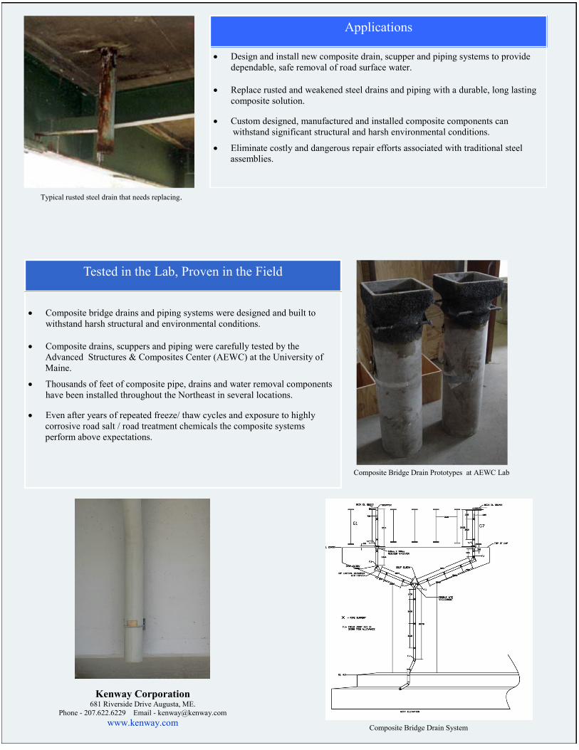
H. End run connections should feature a fiberglass female threaded outlet. Where specifically shown as a clean out, removal pieces shall be made of a threaded PVC plug. The standard plug shall come white in color.
I. The minimum total wall thickness shall be no less than listed on the chart below.
Nominal Size Wall Thickness
(in) (mm) (in) (mm)
4 100 0.125 3.18
6 150 0.125 3.18
8 200 0.125 3.18
10 250 0.125 3.18
12 300 0.125 3.18
14 350 0.125 3.18
16 400 0.125 3.18
18 450 0.125 3.18
J. Runs of pipe shall be supported at spacing no greater than those on the
engineer approved drawings. Supports that have point contact or narrow supporting areas shall not be allowed. Standard sling, clamp, and clevis hangers for use with steel pipes shall be used. Supports shall have 120 degrees of contact with the pipe. If support would be less than 120 degrees of contact, a split fiberglass pipe protective sleeve shall be installed and bonded to the pipe. Split sleeve length shall equal pipe diameter.
K. Strap width shall be 1-1/2 inch for nominal fiberglass pipe size 6 inch to 10
inch. Strap width shall be 2 inch for nominal fiberglass pipe size 12 inch to 14 inch. Hanger’s thickness shall be 3/16 inch.
Pipe Size
Min. Width
(in) (in)
4 1-1/4
6 1-1/2
8 1-1/2
10 1-1/2
12 2
14 2
16 2-1/2
18 2-1/2

Document Prepared by FRP Bridge Drain Pipe – A Product of Grace Composites and Westfall Company, Inc. www.frpbridgedrainpipe.com Phone: (636) 938-6313
L. All connections between piping systems and roadway drain scuppers shall not be rigid. The deck outlet connection shall be made with a free floating collector assembly sized 4 inches larger than the outlet pipe. Assemblies shall include an oversized fiberglass splash guard at each collector unit.
M. All fiberglass pipe and fittings shall be handled and installed according to
the guidelines and procedures recommended in the printed literature of the manufacturer.
N. All fiberglass pipe, fittings and bonding adhesives shall be provided from the same manufacturer.
O. All products to be manufactured in the U.S.A. and are available from Grace Composites, Westfall Company, Inc. and partnering representatives located throughout the country. www.frpbridgedrainpipe.com ©2012 Westfall Company, Inc.

FRP BRIDGE DRAIN PIPE Manufactured by Grace Composites
Lonoke, AR 501-676-9505
Marketed by Westfall Company, Inc.
Eureka, MO 636-938-6313
Installation Instructions for Socket Joint Products
Installation Instructions Video
An installation instructions video is available to view online. In this video, our
team displays the simple steps that are further detailed in this document below. If
there is software on your phone enabling you to use QR scanning technology, the
code to your left can be used to direct you strait to our video on YouTube. You
can also find this video uploaded onto the FRP Bridge Drain Pipe website. The
link to see this video is http://www.frpbridgedrainpipe.com/resources/. If you visit YouTube on a
web browser search for the keywords, “FRP Bridge Drain Pipe Installation Instructions.”
Product Information The adhesive system is offered in a variety of sizes and containers. Currently being offered are ¾
Pint, 1 Gallon and 5 Gallon kits. When properly mixed, the working time of the adhesive is
approximately 20 minutes at 70° F. The catalyst is supplied in bulk quantities for field
measurement.
When using bulk batches of adhesive correctly, the table below can be used as a guide for
estimating the total number of joints possible from each batch size.
Pipe Size 4” 6” 8” 10” 12” 14” 16” 18”
# of Bonds per ¾ Pint Kit 4 2.4 1.7 1.4 N/A N/A N/A N/A
# of Bonds per 1 Gallon Kit 64 37 28 22 14 12 11 8
# of Bonds per 5 Gallon Kit 320 188 142 110 74 64 55 40
Warnings, Precautions & Disposal
Adhesive and catalyst are HIGHLY FLAMMABLE! Catalyst is a STRONG OXIDIZING
AGENT! Wear gloves and eye protection when handling the materials. Try avoiding direct
contact with the adhesive and catalyst; they may cause skin and eye irritation. The catalyst is a
severe eye irritant and direct contact can cause permanent impairment of vision. If skin or eye
contact with the catalyst occurs wash the contaminated area with flowing water for at least 15
minutes. Seek immediate medical attention if contact is made with the eyes.
When a large quantity of adhesive is allowed to harden in a container, the container may reach
approximately 400° F. Do not handle the hot containers without heavy gloves. This exothermic
reaction will generate a heavy, dense, foul-smelling smoke; therefore the container should be
placed outside in an open area until it cools. Avoid inhaling the smoke.
Once the adhesive has reacted and hardened, nothing can be extracted and it is classified as non-
hazardous materials. You may dispose of the materials in the same manner as other solid wastes.
Catalyst bottles when empty are not subject to EPA regulations and can be disposed of in a
normal manner.
Leftover amounts of adhesive and catalyst should be mixed together and allowed to harden.
Once hardened they can be disposed of in a normal manner.
If further information is needed regarding the chemical composition and reactant nature of our
products please consult the Materials Safety Data Sheets that are available by request from
Westfall Company, Grace Composites or your regional sales representative.
Unloading and Storage
Fiberglass pipe, fittings and adhesive require special considerations for storage and handling.
Care should be taken when unloading and handling the materials to prevent impact loads and
point loads on the surface that could damage the pipe and fittings. Pipe should be stored on a flat
surface. The pipe should be supported on boards at least 3 ½” wide with a minimum of 5 boards
being used. Boards should be placed under the pipe and between each layer of pipe when
stacked. For pipe that is shipped from the factory, bundled in 3 - 4’x4’ skids, the pipe may be
stored on the skids as long as the bundle is placed on a flat surface. Fittings should be stored in
the original shipping boxes or stored indoors in a dry and shaded place if removed from their
shipping boxes. Fittings should not be stored outdoors in direct sunlight for long periods of time.
Adhesive must be stored in a dry area where temperatures do not freeze or exceed 90° F. The
storage life of adhesive is 3 months at 90° F and 5 months at 80° F. Adhesive that has been
stored for longer than these recommendations should not be used.
Cutting
Fiberglass pipe can be cut with several acceptable tools. The best overall tool for cutting FRP
pipe is a circular power saw with an abrasive blade. The blade can be carbide or diamond grit
edged or an aluminum oxide blade designed for cutting masonry. Do not use toothed circular saw
blades, they will damage the pipe. You may also use a saber saw or band saw with a grit edge or
very fine (e.g. 22-28 teeth/in) metal cutting blade.
Measure the pipe to allow for fitting and socket dimensions. Scribe or mark a cutting line around
the perimeter of the pipe. Hold the pipe securely, if using a chain vice or other type of
mechanical vice it is necessary to pad the pipe to prevent point loading or crushing of the pipe.
Saw the pipe as smoothly as possible. Use caution to support the free end of the pipe as the cut
nears completions to prevent breaking or splintering of the uncut pipe section. After cutting,
check for square edges, the cut should be squared within 1/8”.
Surface/End Preparation
To achieve a leak free bond it is essential that all surfaces to be bonded are freshly sanded, clean,
dry, dust free and not contaminated with oil or grease, including body oils.

The recommended tool for sanding the pipe surface is a 4 ½” or 7” electric side grinder that uses
a 36-60 Aluminum Oxide grit fiber backed disk. Using flap disks, grinding rocks and belt
sanders will not produce a properly sanded surface in a timely manner. The socket areas of all
fittings are pre-sanded before shipping out of the factory. However it is necessary that the
sockets be freshly sanded once again before the joint is made. The sockets may be hand sanded
with emery cloth or may be sanded with an electric drum or flap sanding wheel. Wipe the sanded
areas free of dust using a clean, dry, lint-free cloth. Avoid touching the sanded surfaces with bare
hands or dirty gloves. If the sanded areas become wet or dirty prior to bonding they must be
sanded again. Never sand the joint more than 2 hours prior to bonding.
Sand the ends of the pipe until it is completely roughened and gloss free with the sanded area
extending ½” beyond the fittings socket insertion depth. The pipe should be able to slip fit into
the socket where it is to be bonded before the adhesive is applied. More than one sanding pass
around the perimeter of the pipe may be necessary to achieve the proper fit. The joint should not
be so tight as to require hammering together.
Adhesive Mixing
Adhesive for bonding the joints is supplied in premeasured ¾ pint kits as well as 1 and 5 gallon
bulk kits. If using bulk kits, before adding the catalyst (Part B), mix the base (Part A) materials
to blend in any liquid that may have separated during shipping and storage.
Open the premeasured kit or measure the desired amount of adhesive from the bulk quantatiy
that will be used. Measure the amount of catalyst that is required for the batch size being mixed.
The amount of catalyst per premeasured ¾ pint kit can range from a minimum of ½ ounce to the
maximum of 1 ounce. When mixing other batch sizes, vary the amount of catalyst used
proportionally. (Example: If mixing 1 ½ pints of adhesive use from 1 to 2 ounces of catalyst.)
The variance in the amount of catalyst used will be dependent upon the temperature while the
mix is being blended. In very hot weather it may be necessary to store the adhesive and catalyst
in a temperature controlled area to ensure the resin does not spoil. In very cold weather it may be
necessary to warm the adhesive and the surfaces to be bonded. Consult the factory for
recommendations if extreme weather is expected during the installation window.
Once both Part A and Part B are added, thoroughly mix the two together with a spatula. Be sure
to scrape the bottom and sides of the container. Mix for at least one minute and ensure the
mixture is consistent in texture throughout. Occasionally stir the mixture during application. If
the consistency of the adhesive starts to drastically stiffen, discontinue use and remove any
adhesive from joints that have not been fully assembled. Solvent may be required to remove the
stiffened adhesive from the bonding surfaces. If removal of hardening adhesive takes place, the
pipe and fitting will need to be sanded once again before the fresh adhesive is applied. The
typical working time after mixing is 5 to 20 minutes depending on the temperature, humidity and
amount of catalyst used.
Applying Adhesive
To apply adhesive, first use a spatula to wet-out the machined area inside the fitting. To “wet-
out” the socket, spread a thin layer of adhesive that is applied with high pressure across the
sanded portion of the socket. A good wet-out is essential for a good joint. Next, apply a second
uniform coat of adhesive to the machined area. The total thickness of the applied adhesive
should measure approximately 1/16”. The thickness of adhesive should result in a small bead of

adhesive becoming visible on the I.D. when the joint is pushed together. Be careful not to
oversaturate the joint with adhesive. If adhesive is applied excessively thick a much larger bead
will form on the inside of the pipe and could result in a partially obstructed flow.
After the socket has been prepared, once again use the spatula to wet-out the sanded area of the
pipe before adding the final coat. To wet-out the plain end run of pipe, use the same procedure
that was utilized to wet-out the socket. Once the pipe has been properly wet-out, the secondary
coating of adhesive for the plain end should be applied to a thickness of approximately 1/8” to
1/4”. When the joint is assembled a bead of adhesive will also be squeezed out around the
exterior circumference of the joint. Any excessive adhesive may be removed and returned to the
mixing container and used for the next joint, as long as it has not begun to harden.
Assembling the Joint
Carefully align and center the pipe end with the fitting and push the parts together until the pipe
bottoms out to the socket lip in the fitting. Once the plain end has been inserted, do not twist the
joint. Align the fitting using a square or level as necessary to ensure proper alignment. Secure the
joint so that it cannot move. Smooth out any adhesive on the outside of the joint with the spatula
to form a fillet between the pipe and fittings. Do not disturb the joint until the adhesive has
shown clear signs of hardening.
Curing the Joint
The joint will fully cure in 24 hours at temperatures of 70° F or above. However joints will begin
to harden in the approximately 20 minutes at 80° F. At this point it can be assumed that the joint
will possess a sufficient strength to allow for movement and handling of the assembly. At
temperatures below 70° F the gel times will be longer and may even require additional heat.
An electric heat gun can be used to accelerate the hardening of the joint. If used, hold the heat
gun approximately 12” from the pipe. There should be constant movement of the heat gun and
heat should be applied at the specified distance until the fillet bead has begun to harden or
become tacky. At this point the heat gun may then be moved to within 6’-8” from the joint, once
again keeping the heat source constantly moving until the joint has becomes secure enough for
movement and handling.
After the joints have gelled an electric heating collar can be used to complete the curing process.