PROJECT MANUAL VOLUME I - Spokane Transit
624
SPOKANE TRANSIT AUTHORITY Boone NW Garage PROJECT #17-STA-579 PROJECT MANUAL VOLUME I November 19, 2017
Transcript of PROJECT MANUAL VOLUME I - Spokane Transit

SPOKANE TRANSIT AUTHORITY Boone NW Garage
PROJECT #17-STA-579
PROJECT MANUAL
VOLUME I
November 19, 2017

THIS PAGE INTENTIONALLY LEFT BLANK

Spokane Transit Authority Boone NW Garage Table of Contents, Volume I
November 19, 2017 TOC - 1
DIVISION 00 – PROCUREMENT AND CONTRACTING REQUIREMENTS 001100 Advertisement 002100 STA Instructions to Bidders 003100 Project Description and Scope of Work 004200 Bid Submittal Checklist 004213 Bid Proposal Form 004215 STA Bid Response 004512 STA Responsibility Criteria 004546.C Disadvantaged Business Enterprise Participation 004546.D Debarment and Suspension Certification 004546.E Certificate of Wage Compliance 005000 STA Form of Contract Between Owner and Contractor 007200.1 General Conditions For Spokane Transit Authority Facility Construction 007300 Special Conditions For Spokane Transit Authority Facility Construction 007346.1 State Prevailing Wage (Spokane County) 007400 Geotechnical Data Geotechnical Report 007500 Environmental Assessment Supplemental Information DIVISION 01 - GENERAL REQUIREMENTS 011000 Summary 012100 Allowances 012200 Unit Prices 012300 Options 012500 Substitution Procedures CSI Substitution Request Form 013100 Project Management and Coordination 013200 Construction Progress Documentation 013233 Photographic Documentation 013300 Submittal Procedures Request for Architect’s Electronic Drawing File(s) 014000 Quality Requirements 014010 Air Barrier System 015000 Temporary Facilities and Controls Project Sign 015639 Temporary Tree and Plant Protection 016000 Product Requirements 017300 Execution 017823 Operation and Maintenance Data 017839 Project Record Documents 017900 Demonstration and Training 019113 General Commissioning
Spokane Transit Authority Boone NW Garage Table of Contents, Volume I
November 19, 2017 TOC - 2
DIVISION 02 - EXISTING CONDITIONS 024116 Structure Demolition 024119 Selective Demolition DIVISION 03 - CONCRETE 033000 Cast-in-Place Concrete DIVISION 05 - METALS 051200 Structural Steel Framing 053100 Steel Decking 054000 Cold-Formed Metal Framing 055000 Metal Fabrications DIVISION 06 - WOOD, PLASTICS, AND COMPOSITES 061053 Miscellaneous Rough Carpentry 064116 Plastic-Laminate-Faced Architectural Cabinets 066400 Plastic Paneling DIVISION 07 - THERMAL AND MOISTURE PROTECTION 071326 Self-Adhering Sheet Waterproofing 071900 Anti-Graffiti and Water Repellent Coating 072100 Thermal Insulation 072600 Vapor Retarders 074213.13 Formed Metal Wall Panels 074213.19 Insulated Metal Wall Panels 076200 Sheet Metal Flashing and Trim 077200 Roof Accessories 077253 Snow Guards 079200 Joint Sealants DIVISION 08 - OPENINGS 082210 Fiberglass Reinforced Door and Frame System 083113 Access Doors and Frames 083323.13 High Performance Overhead Coiling Doors 084313 Aluminum-Framed Storefronts 087100 Door Hardware 088000 Glazing 089119 Fixed Louvers

Spokane Transit Authority Boone NW Garage Table of Contents, Volume I
November 19, 2017 TOC - 3
DIVISION 09 - FINISHES 090000 Finish Schedule 090001 Finish Legend 092216 Non-Structural Metal Framing 092900 Gypsum Board 095113 Acoustical Panel Ceilings 096513 Resilient Base and Accessories 096516 Resilient Sheet Flooring 099113 Exterior Painting 099123 Interior Painting DIVISION 10 - SPECIALTIES 101100 Visual Display Units 101419 Signage Signage Schedule Sign Types 102600 Wall and Door Protection 102800 Toilet, Bath, and Laundry Accessories 104413 Fire Protection Cabinets 105000 Miscellaneous Specialties DIVISION 13 - SPECIAL CONSTRUCTION 133419 Metal Building Systems END OF TABLE OF CONTENTS

Spokane Transit Authority Boone NW Garage Table of Contents, Volume I
November 19, 2017 TOC - 4
THIS PAGE INTENTIONALLY LEFT BLANK
Spokane Transit Authority Boone NW Garage Advertisement for Bids
November 19, 2017 - 1
ADVERTISEMENT FOR BIDS
Sealed bid proposals will be accepted for the following project: PROJECT NO.: 17-STA-579 TITLE: Boone NW Garage AGENCY: Spokane Transit Authority PROJECT MANAGER: Jessica Charlton, Project Manager PUBLIC BID OPENING: 3:00 P.M., Wednesday December 20, 2017 Spokane Transit Authority (Owner) 1230 W Boone Avenue, Spokane, WA 99201 PRE-BID WALK-THROUGH: 3:00 P.M., Thursday, November 30, 2017
Spokane Transit Authority (Owner) 1230 W Boone Avenue, Spokane, WA 99201 Meeting room TBD, site tour after meeting Contractors may obtain electronic copies of plans and specifications from the Project Manager, Jessica Charlton by phone at (509)325-6049 or email at [email protected]. Use of MWBE contractors and suppliers is encouraged but not mandatory. Contractors submitting bids may contact the Washington State Office of Minority and Women's Business Enterprise to obtain information on certified firms.
The minimum prevailing wage provisions of Washington state law apply to this locally funded project.
The Owner reserves the right to reject or accept any or all bids and to waive minor informalities in the process.
No contractor submitting may withdraw their bids after hour set for opening thereof unless contract award is delayed for a period exceeding ninety (90) days.
Spokane Transit is an Equal Employment Opportunity (EEO) organization which does not discriminate against any prospective supplier on the basis of race, color, creed, national origin, sex, sexual orientation, gender identity, or presence of any sensory, mental, or physical disability in the consideration of contract award. The successful contractor submitting a bid will be required to comply with all EEO federal, state, and local laws and regulations. Spokane Transit assures nondiscrimination in accordance with Title VI of the Civil Rights Act of 1964. For more information, see www.spokanetransit.com. Upon request, alternative formats of this information will be produced for people who are disabled. The meeting facility is accessible for people using wheelchairs. For other accommodations, please call (509) 325-6094 (TTY WA Relay 711) at least forty-eight (48) hours in advance. END OF ADVERTISEMENT FOR BIDS

Spokane Transit Authority Boone NW Garage Advertisement for Bids
November 19, 2017 - 2
THIS PAGE INTENTIONALLY LEFT BLANK

Spokane Transit Authority Section 002100
Boone NW Garage STA Instructions to Contractors Submitting Bids
November 19, 2017 002100 - 1
SECTION 002100 – STA INSTRUCTIONS TO CONTRACTORS SUBMITTING BIDS
DEFINITIONS
A. Addenda are written or graphic instruments, approved and issued by the Owner prior to the time
designated for Opening of Bids, which amend, modify or interpret the Bidding Documents by additions,
deletions, clarifications, or corrections.
B. An Alternate Bid (or Alternate) is the amount stated in the Bid to be added or deducted from the
amount of the Base Bid if the corresponding change in project scope or materials or methods of
construction described in the Bidding Documents is accepted.
C. A Bid is the submission of a complete and properly signed authorized solicitation form (Bid Proposal
Form) together with Bid Bond, if applicable, and the certifications and representations required to comply
with the Invitation for Bid.
D. Base Bid is the sum stated in the Bid for which the Bidder offers to perform the work described as the
Base, to which work may be added or deducted from sums stated in Alternate Bids (if any).
E. Bidder is one who submits a Bid for a prime contract with the Owner for the Work described in the
Construction Documents.
F. A Non-responsive Bid is any Bid which fails to conform in all respects to the material requirements of
the Bidding Documents or imposes conditions which would modify requirements of the Bidding
Documents or would limit a bidder's liability to the Spokane Transit Authority so as to give the bidder an
advantage over the Bidders as determined by the Spokane Transit Authority.
G. Responsible Bidder means a contractor who meets the criteria listed in RCW 39.04.350.
H. Unit Price is an amount stated in the Bid as a price per unit of measurement or materials or services as
described in the Construction documents as defined in the General Conditions of the Contract between
STA, as Owner, and the Contractor.
Spokane Transit Authority Section 002100
Boone NW Garage STA Instructions to Contractors Submitting Bids
November 19, 2017 002100 - 2
PART 1 - GENERAL
1.1 EXPLANATION TO PROSPECTIVE CONTRACTORS SUBMITTING BIDS
A. Materials submitted in response to this competitive procurement shall become the property of
Spokane Transit Authority. All received Proposals shall be deemed public records as defined in Ch.
42.56RCW “Public Records Act.” Any information in the Bid that the Contractor desires to claim
as proprietary and exempt from discloser under the provisions of state law shall be clearly
designated. Each page claimed to be exempt from disclosure must be clearly identified by the word
“Confidential” printed on it. Marking the entire Bid exempt from discloser will not be honored.
STA will consider a Contractor’s request for exemption from disclosure; however, the agency will
make a decision predicated upon state law and regulations. If any information is marked as
proprietary in the Bid, it will not be made available until the affected Contractor has been given an
opportunity to seek a court injunction against the requested disclosure. STA assumes no liability for
disclosure of proprietary material submitted by Contractors. Bid submittals shall be considered
public documents under applicable Washington state law and shall be available for inspection and
copying by the public, except to the extent portions of the submittals are otherwise protected under
applicable law. Each Contractor will be responsible for protecting any disclosure of its submittal
under applicable law.
B. Any prospective contractor submitting bids desiring an explanation or interpretation of the
solicitation, drawings, specifications, etc., must submit a request in writing to the
Architect/Engineer (A/E) seven (7) calendar days before the bid due date. Oral explanations or
instructions given before the award of a contract will not be binding. Any information given a
prospective contractor submitting bids concerning a solicitation will be furnished promptly to all
other prospective contractors submitting bids by addendum to the solicitation, if that information is
necessary in submitting bids or if the lack of it would be prejudicial to other prospective contractors
submitting bids.
C. STA is committed to ensuring that all forms regardless of race, color, sex or national origin have
equal opportunity to participate in STA contracts. Therefore, STA has established an annual agency
goal for Disadvantaged Business Enterprise (DBE) participation in its contracting opportunities. In
accordance with the legislative findings and policies set forth in Chapter 39.19 RCW STA
encourages participation in all of its contracts by Minority Business Enterprises (MBE), Women
Owned Business Enterprise (WBE), and Minority Women Owned Business Enterprise (MWBE)
firms certified by the Office of Minority and Women’s Business Enterprises (OMWBE).
Participation may be either on a direct basis in response to this invitation or as a subcontractor to a
contractor submitting bids. However, unless required by federal statutes, regulations, grants, or
contract terms referenced in the contract documents, no preference will be included in the
evaluation of bids, no minimum level of DBE/MBE/WBE/MWBE participation shall be required as
a condition for receiving an award, and bids will not be rejected or considered non-responsive on
that basis. Any affirmative action requirements set forth in federal regulations or statutes included or
referenced in the contract documents will apply.
D. In addition to the payment and performance bond required by work law the Contractor shall
purchase and maintain in a company or companies lawfully authorized and admitted to do business
in the State of Washington possessing a Best’s policyholder’s rating of A- or better and a financial
rating of no less than VII, and reasonably acceptable to STA, an occurrence-based Commercial
General Liability Insurance Policy which shall provide bodily injury and property damage liability
on its own operations and vehicles on Work the Contractor may subcontract or sublet to others, in
no less than the amounts specified in Part 2 of the attached STA General Conditions.

Spokane Transit Authority Section 002100
Boone NW Garage STA Instructions to Contractors Submitting Bids
November 19, 2017 002100 - 3
E. The general description and scope of work for the project can be found in Section 003100 of this
document.
1.2 PREPARATION OF BIDS – CONSTRUCTION
A. Bids must be: (1) submitted on the bid proposal forms, or copies of forms, furnished by the Owner
or the Owner’s agent, and (2) signed in ink. The person signing a bid must initial each change
appearing on any bid form. If the bid is made by a corporation, it shall be signed by the
corporation’s authorized designee. The address of the contractor submitting bids shall be typed or
printed on the bid form in the space provided.
B. The bid form may require contractors submitting bids to submit bid prices for one or more items on
various bases, including: (1) lump sum base bid; (2) lump sum bid alternate prices; (3) unit prices;
or (4) any combination of items 1 through 3 above.
C. If the solicitation includes alternate bid items, failure to provide a bid on the alternates may
disqualify the bid. If quoting on all items is not required, contractors submitting bids should insert
the words “no bid” in the space provided for any item on which no price is submitted.
D. Substitute bid proposals will not be considered unless this solicitation authorizes their submission.
1.3 BID GUARANTEE
A. Acceptable forms of bid guarantee are: A bid bond or postal money order, or certified check or
cashier’s check made payable to Spokane Transit Authority. The Owner will return bid guarantees
(other than bid bond) to unsuccessful contractors submitting bids as soon as practicable, but not
sooner than the execution of a contract with the successful contractor submitting bids. The bid
guarantee of the successful contractor submitting bids will be returned to the successful contractor
submitting bids with its official notice to proceed with the work of the contract.
B. The contractor submitting bids will allow 90 days from bid opening date for acceptance of its bid by
the Owner. The contractor submitting bids will return to the Owner a signed contract, insurance
certificate and bond or bond waiver within 15 days after receipt of the contract. If the apparent
successful contractor submitting bids fails to sign all contractual documents or provide the bond and
insurance as required or return the documents within 15 days after receipt of the contract, the Owner
may terminate the award of the contract.
C. In the event a contractor submitting bids discovers an error in its bid following the bid opening, the
contractor submitting bids may request to withdraw its bid under the following conditions:
1. Written notification is received by the Owner within 24 hours following bid opening.
2. The contractor submitting bids provides written documentation of the claimed error to the
satisfaction of the Owner within 72 hours following the bid opening.
The Owner will approve or disapprove the request for withdrawal of the bid in writing. If the
contractor’s request for withdrawal of its bid is approved, the contractor submitting bids will be
released from further obligation to the Owner without penalty. If it is disapproved, the Owner may
retain the contractor’s bid guarantee.
Spokane Transit Authority Section 002100
Boone NW Garage STA Instructions to Contractors Submitting Bids
November 19, 2017 002100 - 4
1.4 ADDITIVE OR DEDUCTIVE BID ITEMS
A. The low contractor submitting bids, for purposes of award, shall be the responsive contractor
submitting bids offering the low aggregate amount for the base bid item, plus additive or deductive
bid alternates selected by the Owner, and within funds available for the project.
B. The contractor submitting bids agrees to hold all bid alternate prices for ninety (90) days from date
of bid opening.
1.5 ACKNOWLEDGEMENT OF ADDENDA
A. Contractors submitting bids shall acknowledge receipt of all addenda to this solicitation by
identifying the addenda numbers in the space provided for this purpose on the bid proposal form.
Failure to do so may result in the bid being declared non-responsive.
1.6 SITE INVESTIGATION AND CONDITIONS AFFECTING THE WORK
A. The contractor submitting bids acknowledges that it has taken steps necessary to ascertain the nature
and location of the work, and that it has investigated and satisfied itself as to the general and local
conditions which can affect the work or its cost, including but not limited to (1) conditions bearing
upon transportation, disposal, handling, and storage of materials; (2) the availability of labor, water,
electric power, and road; (3) uncertainties of weather, river stages, tides, or similar physical
conditions at the site; (4) the conformation and conditions of the ground; and (5) the character of
equipment and facilities needed preliminary to and during the work. The contractor submitting bids
also acknowledges that it has satisfied itself as to character, quality, and quantity of surface and
subsurface materials or obstacles to be encountered insofar as this information is reasonably
ascertainable from an inspection of the site, including exploratory work done by the Owner, as well
as from the drawings and specifications made a part of this contract. Any failure of the contractor
submitting bids to take the actions described and acknowledged in this paragraph will not relieve the
contractor submitting bids from responsibility for estimating properly the difficulty and cost of
successfully performing the work.
B. If Bidder is unable to attend the scheduled Pre-Bid meeting, please contact STA to arrange a
separate site visit. Bids submitted by contractors that have not either attended a pre-bid
meeting or inspected the sites in the presence of STA staff will be considered non-responsive.
1.7 TIME OF COMPLETION
A. Work may begin when the Contractor receives a formal “Notice to Proceed.” Contractor shall
proceed with promptness and dispatch and shall achieve Substantial Completion on or before June
12, 2019.
1.8 LIQUIDATED DAMAGES
A. The Contractor agrees to pay to STA liquidated damages in the amount of $500.00 for each day the
Contractor fails to provide services or respond to an STA request for services hereinafter provided.
These liquidated damages are for the purpose of any delay or impact caused to STA by virtue of the
Contractor’s acts or omissions and do not cover any other actual or consequential damages other
than delay. STA and the Contractor agree that such damage cannot be reasonably determined at this

Spokane Transit Authority Section 002100
Boone NW Garage STA Instructions to Contractors Submitting Bids
November 19, 2017 002100 - 5
time. Such damages are very difficult to accurately estimate because of numerous factors,
including, but not limited to inconvenience to STA. Further, the parties agree this is a reasonable
forecast of all factors now known and available for consideration relating to the delay caused by
failure to perform. Liquidated damages shall be deducted from the contract by change order.
1.9 WAGE RATE SCHEDULES
A. The Scope of Work for this project constitutes a public work under state law and therefore the
Contractor shall pay the highest prevailing wage rate by trade or occupation as specified by the
State of Washington, Department of Labor and Industries. The State of Washington wage rates are
current at the time of submission and are available through website provide in Section 007346.1 of
this document. It is the responsibility of the prospective bidder to verify these publications are
current at the time of bidding
1. Certified Payrolls for the prime and all subcontractors may accompany all applications for
payment.
2. An approved Intent to Pay Prevailing wage form must be received by STA for the contractor
and any subcontractors prior to commencement of any work.
B. Any disputes as to wage rates will be referred to the US Secretary of Labor and the Director of
Labor and Industries for the State of Washington who will determine the prevailing local wage rate
for the trade in dispute.
1.10 TAXES
A. A portion of this contract qualifies under WAC 458-20-171 as “Public Road Construction”, herein
after referred to as Rule 171. All work associated with the vehicle servicing and storage facility
itself, all electrical and mechanical infrastructure / components within the facility, the bus washer
and associated infrastructure, exterior pathways and exterior lighting leading to and from the
facility, utility side services, public utility relocation, paving repairs, sidewalk / curb / ramps within
the public ROW Qualifies as a pubic road work therefore as Rule 171. All work associated with
grading / earthmoving / site prep, the underground fuel storage tank (including associated
mechanical and electrical), the generator and its infrastructure (pads, conduit, wiring, ATS,
transformers, etc.), anything to do with fiber, anything to do with cable tv, secure access and all
infrastructure, employee parking lots and all associated infrastructure (lighting, pathways), all
landscaping, irrigation, fencing, anything related to contaminated soils, does not qualify as Rule
171.
B. Bid amounts that relate to items not covered under Rule 171 shall not include Washington State
Sales Tax (WSST). All other taxes imposed by law shall be included in the Bid amount. The
Owner will include WSST in progress payments. The Contractor shall pay the WSST to the
Department of Revenue and shall furnish proof of payment to the Owner if requested.
C. Rule 171: The Contractor shall pay taxes, including sales tax, for the work or portions thereof
provided by the Contractor and these taxes shall be included in the Contract amount.
State of Washington sales tax is payable on the “selling price” or “gross proceeds of sale” of the
“tangible personal property” as these terms are defined in WAC 458-20-107 (Rule 107) except as
excluded by WAC 458-20-171 (Rule 171). When Rule 171 applies, it takes precedence over Rule
107.
Spokane Transit Authority Section 002100
Boone NW Garage STA Instructions to Contractors Submitting Bids
November 19, 2017 002100 - 6
Contractors are advised that they are considered the end consumers of all material, including
prefabricated and pre-cast items, equipment and supplies used or consumed by them in performing
the work, and must pay an applicable retail sales tax/use tax to their material men and suppliers. In
order to maximize the sales tax exemption, Contractors are encouraged to have all material
delivered to the job site for consumption. Work performed away from the job site should be
minimized in order to maximize the sales tax exemption. If the Contractor has questions about the
application of Rule 171, the Contractor is advised to contact the department of Revenue.
The Contract Amount must include labor, overhead, profit and applicable sales tax on materials,
pursuant to Washington State Department of Revenue Rule 171. Contractors are cautioned against
paying sales tax more than once on materials used or consumed, such as by paying sales tax to
material men or suppliers, and again remitting sales tax to the state on total costs.
All applicable taxes, which the Contractors are required to pay, including retail sales/use tax as
specified above, shall be included by them in their proposed Bid Prices for qualifying work under
their proposal. No adjustment will be made in the amount to be paid by STA under the contract
because of any misunderstanding by or lack of knowledge of the Bidder/Contractor as to their
liability for, or the amount of any taxes or because of any increase in tax rates imposed by any
federal, state or local government. Bidders who do not appropriately apply Rule 171 may be
considered non-responsive.
D. NOTE: Contractor must bond for total contract amount including WSST.
1.11 BID AMOUNTS
A. The bid prices shown for each item on the bid proposal shall include all labor, material, sales tax as
described in paragraph 1.10, equipment, overhead and compensation to complete all of the work
for that tem.
B. The actual cost of building permit (only) and the public utility hookup fees will be a direct
reimbursement to the Contractor or paid directly to the permitting agency by the Owner. Fees for
these permits should not be included by the Contractor submitting bids in the bid amount.
C. The Contractor submitting bids agrees to hold the base bid prices for ninety (90) days from date of
bid opening.
1.12 SUBMISSION OF BIDS
A. Bid Proposals must be submitted on or before the time specified in the Advertisement for Bids or as
extended in Contract Documents.
B. The Bid Proposal shall be submitted in a sealed envelope addressed to the office specified in the
Advertisement for Bids. Oral, telephonic, electronic, for facsimile bids are invalid and will not
receive consideration. The envelope shall have printed on the outside:
1. The project number and description.
2. The name and address of the contractor submitting bids.
3. Identification as Bid Proposal.
Spokane Transit Authority Section 002100
Boone NW Garage STA Instructions to Contractors Submitting Bids
November 19, 2017 002100 - 7
C. Prior to the bid opening, the Owner’s representative will designate the official bid clock. Any part
of the bid proposal or bid modification not received prior to the times specified, per the designated
bid clock, will not be considered and the bid will be returned to the contractor unopened.
D. A bid may be withdrawn in person by the authorized representative of the contractor submitting bids
before the opening of the bids. The representative of the contractor submitting bids will be required
to show ID and sign on bid summary sheet before it will be released.
E. People with disabilities who wish to request special accommodation, (e.g., sign language
interpreters, Braille, etc.) need to contact the Owner ten (10) working days prior to the scheduled
bid opening.
1.13 CONSIDERATION OF BIDS
A. Spokane Transit Authority shall have the right to reject any or all bids and to reject bids considered
non-responsive including but not limited to Bids not accompanied by any required bid security,
certifications, or data required by the Bidding Documents or a Bid not signed by the authorized
legal representative.
B. The Owner shall have the right to waive any informality or irregularity in any Bid received.
C. In the event that a single bid is received, Spokane Transit will conduct a cost/price analysis of the
bid. This analysis will compare the price and quality of the proposed equipment with that involved
in recent similar purchases with similar specifications made by this or other governmental agencies
in an attempt to determine the competitive integrity of the submitted bid.
1.14 BID RESULTS
A. After the Bid Opening, Contractors submitting bids may obtain bid results from the Owner. Bid
results may also be obtained from the A/E.
1.15 LOW RESPONSIBLE
A. Mandatory Responsibility Criteria: Before award of a public works contract, a contractor submitting
bids must meet the following mandatory responsibility criteria under RCW 39.04.350 (1) to be
considered a responsible contractor submitting bids and qualified to be awarded a public works
project. The contractor submitting bids must:
1. At the time of bid submittal, have a certificate of registration of contractor in compliance with
Chapter 18.27 RCW;
2. Have a current state unified business identifier number;
3. If applicable, have industrial insurance coverage for the employees of the contractor
submitting bids working in Washington as required in Title 51 RCW; an employment security
department number as required in Title 50 RCW; and a state excise tax registration number as
required in Title 82 RCW;
4. Not be disqualified from quoting on any public works contract under RCW 39.06.010 or
39.12.065(3); and
5. If quoting on a public works project subject to the apprenticeship utilization requirements in
RCW 39.04.320, not have been found out of compliance by the Washington state
apprenticeship and training council for working apprentices out of ratio, without appropriate

Spokane Transit Authority Section 002100
Boone NW Garage STA Instructions to Contractors Submitting Bids
November 19, 2017 002100 - 8
supervision, or outside their approved work processes as outlined in their standards of
apprenticeship under chapter 49.04 RCW for the one-year period immediately preceding the
date of the bid solicitation.
B. Supplemental Responsibility Criteria: In addition to the mandatory contractor submitting bids
responsibility, the Owner may adopt relevant supplemental criteria for determining contractor
submitting bids responsibility applicable to a particular project which the contractor submitting bids
must meet (RCW 39.04.350 (2)).
1. If applicable, the Owner shall consider an overall accounting of the attached supplemental
criteria for determining contractor submitting bids responsibility “DIVISION 00
RESPONSIBILITY CRITERIA”.
2. At least seven (7) days prior to the bid submittal deadline, a potential contractor submitting
bids may request that the Owner modify the supplemental responsibility criteria. The Owner
will evaluate the information submitted by the potential contractor submitting bids and
respond before the bid submittal deadline. If the evaluation results in a change of the criteria,
the Owner will issue an addendum to the quoting documents identifying the new criteria.
3. Upon Owner’s request, the apparent low contractor submitting bids must supply the requested
responsibility information within two (2) business days of request by Owner. Withholding
information or failure to submit all the information requested within the time provided may
render the bid non-responsive.
4. Upon request of the Owner, a Bidder whose proposal is under consideration for award of
Contract shall submit promptly satisfactory evidence of his/her financial resources,
experience, organization, and equipment available for performance of the Contract on AIA
Form A305 “contractor’s Qualification Statement” or similar form approved by the Owner.
5. If the Owner determines that the apparent low contractor submitting bids is not responsible,
the Owner will notify the contractor submitting bids of its preliminary determination in
writing.
6. Within three (3) days after receipt of the preliminary determination, the contractor submitting
bids may withdraw its bid or request a hearing where the contractor submitting bids may
appeal the preliminary determination and present additional information to the Owner.
7. The Owner will schedule a hearing within three (3) working days of receipt of the
contractor’s request. The hearing members will include a STA Executive or designee, and
Project Manager.
8. The Owner will issue a Final Determination after reviewing information presented at the
hearing.
9. If the Owner determines a contractor submitting bids to be not responsible, the Owner will
provide, in writing, the reasons for the determination. If the final determination affirms that
the contractor submitting bids is not responsible, the Owner will not execute a contract with
any other contractor submitting bids until two (2) business days after the contractor
submitting bids determined to be not responsible has received the final determination.
10. The Owner’s Final Determination is specific to this project, and will have no effect on other
or future projects.
1.16 CONTRACT AWARD
A. The Owner will evaluate bids responsiveness and responsibility.
1. A bid will be considered responsive if it meets the following requirements:
a. It is received at the proper time and place.
b. It meets the stated requirements of the bid proposal.
c. It is accompanied by a bid guarantee, if required.

Spokane Transit Authority Section 002100
Boone NW Garage STA Instructions to Contractors Submitting Bids
November 19, 2017 002100 - 9
2. A bid will be considered responsible if it meets the following requirements:
a. It is submitted by a licensed/registered contractor within the state of Washington at the
time of bid opening and is not banned from quoting by the Department of Labor and
Industries.
b. It meets the mandatory responsibility criteria established in RCW 39.04.350 for Prime
and Subs and an overall accounting of the supplemental responsibility criteria
established for the project.
B. The Owner reserves the right to accept or reject any or all bid proposals and to waive informalities.
C. The Owner may negotiate bid price adjustments with the low responsive contractor submitting bids,
including changes in the contract documents, to bring the bid within the available funding per RCW
39.04.015.
D. The apparent low contractor submitting bids, for purpose of award, shall be the responsive and
responsible contractor submitting bids offering the low aggregate amount for the base bid plus
selected additive or deductive bid alternates and meeting all other bid submittal requirements.
E. The Contract will only become effective when signed by the Owner. Prior to the Owner’s signature,
any and all costs incurred shall be the sole responsibility of the contractor submitting bids.
F. The Contractor must purchase and maintain insurance coverage as stated in Part 2 of Spokane
Transit Authority’s Public Works Construction Project General Conditions.
G. Note: AIA Payment Bond and Performance Bond forms (A312) are required. These forms will not
be provided by the Owner.
1.17 CONTRACT DOCUMENTS
A. The Contract Documents under which it is proposed to execute this work consists of all material
bound herein, plus any addenda incorporated into the documents.
B. These Contract Documents are intended to be mutually cooperative and to provide all details
reasonably required for the execution of the proposed work. Any person contemplating the
submission of a proposal shall have thoroughly examined all of the various parts of these
documents, and should there be any doubt as to the meaning or intent of said Contract Documents,
the Bidder should request the Architect/Engineer, in writing (at least seven (7) working days prior to
bid opening), and interpretation thereof. Any interpretation or change in said Contract Documents
will be made only in writing, in the form of addenda to the documents and will be furnished to all
Bidders receiving a set of documents, who shall indicate receipt of same in the space provided on
the proposal form. The Owner will not be responsible for any other explanation or interpretation of
said documents.
1.18 DISCREPANCIES & CONTRACT DOCUMENT REVIEW
A. The intent of Spokane Transit Authority and Federal Funded Project Contract Documents is to
describe a complete Project. These Contract Documents are complimentary. What is required by
one part of the Contract Documents shall be binding as if required by all.

Spokane Transit Authority Section 002100
Boone NW Garage STA Instructions to Contractors Submitting Bids
November 19, 2017 002100 - 10
B. In the event of a discrepancy between Spokane Transit Authority and Federal Funded Project
Contract Documents, the Contractor will use the Contract Document that imparts the highest cost to
their bid and/or longest delay in their schedule. It is the responsibility of the Contractor to bring
these discrepancies to the attention of the Architect as soon as they are discovered.
1.19 PROTEST PROCEDURES
A. STA maintains a set of protest procedures. If any bidder desires this information, it may be
obtained by calling the Office of the Purchasing Manager, Jacqueline Tjards at (509) 325-6032.
PART 2 - PRODUCTS (Not used)
PART 3 - EXECUTION (Not used)
END OF SECTION 002100

Spokane Transit Authority Section 003100 Boone NW Garage STA Project Description and Scope of Work
November 19, 2017 003100 - 1
SECTION 003100 – STA PROJECT DESCRIPTION AND SCOPE OF WORK PROJECT DESCRIPTION This project includes: The Work of Project is defined by the Contract Documents and consists of the follow-ing:
1. Building Demolition and Site Demolition which includes portions of existing streets and parking lot. 2. Earthwork and utilities. 3. Construction of a parking lot. 4. Construction of a garage building for storage of Spokane Transit Authority vehicles with fueling and
washing facilities.
Project Location: 1224 N. Cedar Street, Spokane, WA 99201.
Time Line: The Contractor agrees to coordinate the completion of all construction and achieve Substantial Completion by June 12, 2019, beginning on the day of commencement as stated in a Notice to Proceed.
Exclusions: Purchase and installation of shelters
PROJECT GENERAL SCOPE OF WORK The work shall generally consist of:
1. Obtain and pay for all required fees and permitting 2. Establish and maintain jobsites safety, security and traffic control measures. 3. Coordinate with the appropriate department within the City of Spokane. (i.e. permitting, public
works, planning, urban forestry, as needed for successful completion of the project) 4. Prep and grade existing site, disposing of any debris in a legal manner, as per plan and specification 5. Construct new parking lot, striping, curbing, lighting, stormwater, landscaping, etc. as per plan and
specification 6. Relocate/reconfigure public utilities etc. as per plan and specification 7. Properly abandon old utilities as per plan and specification 8. Construct new building, associated infrastructure, associated landscaping, etc. as per plan and specifi-
cation 9. Construct all hardscaping and landscaping improvement along N. Cedar St., W. Sinto Ave., N. Jeffer-
son St., and W. Sharp Ave. as per plan and specification 10. Record all “as-built” information for delivery to Owner as required for final closeout 11. Provide O&M manuals to Owner as required for final closeout 12. All work to be completed as shown and specified on the associated plan and specifications for the
project. All work shall meet/exceed all codes, utility locating, rules and regulations, as set forth by the City, County and State of Washington. Contractor shall perform work in accordance with the Washington State Department of Labor and Industries Safety Standards. Contractor is responsible for the supply of all equipment, materials, and labor necessary to complete the pro-ject. Contractor is responsible for making arrangements for staging of materials and equipment if necessary. Contractor shall be responsible for the removal of all trash and waste materials from this project. All items that are disposed of shall be approved by the Project Manager and/or designee. Damages resulting from Con-tractor negligence shall be repaired immediately at no cost to STA. The Contractor shall take all precautions necessary to protect private property and the public during the construction period. All work will be subject to inspection and acceptance by STA’s project manager or designee prior to payment.

Spokane Transit Authority Section 003100 Boone NW Garage STA Project Description and Scope of Work
November 19, 2017 003100 - 2
STA reserves the right to increase or decrease the amount of related services listed in the scope of work for a fairly negotiated price. END OF SECTION 003100

Spokane Transit Authority Section 004200 Boone NW Garage Section Title
November 19, 2017 004200 - 1
SECTION 004200 STA BID SUBMITTAL CHECKLIST
BID CHECKLIST- BOONE NW GARAGE 17-STA-579
To be included with Bid Proposal Form when you submit your Bid. Failure of the contractor submitting a bid to submit these forms with the bid shall render the bid non-responsive and shall be grounds for rejection of said bid.
C H E C K O F F E A C H O F T H E F O L L O W I N G A S C O M P L E T E D , A N D I N C L U D E D W I T H T H I S P R O P O S A L :
� Section 004200 - STA Bid Submittal Checklist - Statement of Compliance, signed and dated below.
� Section 004213 - Bid Proposal Form: Submitted on appropriate form, filled out legibly and completely.
� Section 004215 - Bid Response: Submitted on appropriate form, filled out legibly and completely.
� Section 004512 – STA Responsibility Criteria: Submit filled out legibly and completely.
� Bid Security attached in the Amount of 5% of Total Bid (Base Bid including applicable WSST), see instructions to contractors.
� Work Plan: The Contractor submitting a bid must provide the following required information with the bid form. Failure to submitsuch information to the satisfaction of the Owner may render the bid non-responsive. The Contractor’s work plan is to include with description the following minimum elements:
a. Installation of safety barriers and traffic control plansb. Phasingc. Final cleanupd. Final closeout
� Bid is submitted in a sealed opaque envelope, identified with the following: Project Name: Boone NW Garage Project Number: 17-STA-579
Contractor’s Name: Contractor’s Address:
NOTE: If mailed, enclose sealed bid in a separate mailing envelope with the notation “Sealed Bid Enclosed”.
STATEMENT OF COMPLIANCE
The undersigned has reviewed, read and fully understands these Bid Documents and this checklist, fully complies therein, and certifies that all required elements, as marked herein and contained within the specification are included in this Bid Proposal.
Authorized Signature: Date:
END OF SECTION 004200
Spokane Transit Authority Section 004200 Boone NW Garage Section Title
November 19, 2017 004200 - 2
THIS PAGE INTENTIONALLY LEFT BLANK

Spokane Transit Authority Section 004213 Boone NW Garage Bid Proposal Form
November 19, 2017 004213 - 1
SPOKANE TRANSIT AUTHORITY 1230 W. BOONE AVE
SPOKANE, WASHINGTON 99201
BID PROPOSAL – BOONE NW GARAGE
Name of Firm (Contractor submitting bid): ______________________________________ Each bid shall constitute an offer to STA as outlined herein and no bidder may withdraw his/her bid after the hour set for the bid opening thereof except under the conditions explained in the Instructions to Contractors Section.
In compliance with the contract documents, the following bid proposal is submitted:
Base Bid “A” (Non-Rule 171 Items) $
(Please print dollar amount in space above) (Do Not Include Washington State Sales Tax)
Base Bid “B” (Rule 171 Items)
$
(Please print dollar amount in space above) (Rule 171, Does Include Washington State Sales Tax)
Additive Bid Option
Photovoltaic Roof Panels $ (Do Not Include Washington State Sales Tax)
Unit Prices (Specify whether additive or deductive)
No. 1: Removal of uncontaminated soil designated by the Owner to be unsatisfactory and replacement with satisfactory soil $
The unit price shall include full compensation for the cost of labor, materials, equipment, overhead, profit and any additional cost associated with the unit bid.
(Do Not Include Washington State Sales Tax)
Basis of Award: The lowest bid shall be the lowest Total Base Bid price (Base Bid “A” + Base Bid “B”) plus bid options selected by the Owner and within funds available for the project. If the Owner awards a contract it will go to the responsive and responsible bidder who submitted the lowest bid as determined by this basis of award. Additive Bid Option: Bid options shall include full compensation for the cost of labor, materials, equipment, overhead, profit, and any additional cost associated with the option. The Owner reserves the right to accept or reject any or all bid prices within ninety (90) days of the bid date. Bidder agrees and understands that any additional taxes, permits, bonds, prevailing wage certifications, etc. Applicable to this project, have been included in the above Bid Amounts.

Spokane Transit Authority Section 004213 Boone NW Garage Bid Proposal Form
November 19, 2017 004213 - 2
PRODUCTS/BRANDS OTHER THAN SPECIFIED IN BID DOCUMENT TO BE USED: NOTE: Any deviation from technical specifications provided in bid document must be approved in advance by Owner.
Bidder Name & Signature: END OF SECTION 004213
Spokane Transit Authority Section 004215 Boone NW Garage Bid Response
November 19, 2017 004215 - 1
TO: SPOKANE TRANSIT PLANNING DEPARTMENT 1230 West Boone Avenue Spokane, Washington 99201-2686
RE: Project Number: 17-STA-579 Boone NW Garage
NAME OF FIRM SUBMITTING BID:
Each bid shall constitute an offer to STA as outlined herein and no bidder may withdraw his bid after the hour set for the bid opening thereof except under the conditions explained in the Instructions to Bidders Section. EXAMINATION OF DOCUMENTS:
A. Having carefully examined all Bidding Documents entitled “Boone NW Garage” by the Spokane Transit Authority, as well as the site and local conditions affecting the work, the undersigned proposes to perform all work in accordance with the Contract Documents for compensation to be computed from the enclosed bid amounts.
B. Receipt of the following Addenda to the Specifications and Drawings is hereby acknowledged:
Addendum No. Date_______________
Addendum No. Date_______________
Addendum No. Date_______________
REJECTION: STA reserves the right to reject any or all bid proposals, portions or parts thereof and to waive minor irregularities in bidding. Special attention will be directed to the qualifications of the bidders when considering an award of contract.
TIME FOR COMPLETION: The Contractor agrees to coordinate the completion of all construction work and achieve Substantial Completion by June 12, 2019.
LIQUIDATED DAMAGES: Per the STA Instructions to Contractors Submitting Bids
SUBMITTAL: The “Bid Response Documents”, “Bid Proposal Form”, and “Responsibility Criteria” constitute the Bid Proposal when completed and submitted. Please do not submit the entire Invitation for Bid manual.
PRICES: Each bid item will be priced unless stated otherwise.
UNIT PRICE: Unit prices, if requested, shall govern in case of extension error.
Bidder Name:

Spokane Transit Authority Section 004215 Boone NW Garage Bid Response
November 19, 2017 004215 - 2
FREIGHT: Bid price(s) to include all freight costs to the project site.
COMPLETION OF BID PROPOSAL FORM:
All bidding procedures and other requirements of Instructions to Bidders and all Contract Documents have been followed.
ATTACHMENTS:
A. Bid security as required by the Bidding Documents in the amount of 5% of the Base Bid.
B. Detailed Work Plan based on project plans, pre-bid walk-through, project summary and specifications.
AWARD OF CONTRACT:
A. If written notice of acceptance of all or part of this submittal is mailed, sent electronically, or delivered to undersigned within ninety (90) days after opening of proposals, the undersigned will, within fifteen (15) days after date of such notice, execute and deliver the Form of Agreement as specified and furnish Insurance Certificates, Performance Bonds, and Labor and Material Payment Bonds as required.
B. If the undersigned fails to complete the above requirements, amount of Bid Security shall be forfeited to the Owner.
Bidder Name:
Spokane Transit Authority Section 004215 Boone NW Garage Bid Response
November 19, 2017 004215 - 3
I CERTIFY that no final determination of violation of RCW 50.12.070(1)(b), or 82.32.070(1)(b) has been made by the Washington State Departments of Employment Security, Labor and Industries or Revenue respectively dated within two (2) years of the date of the opening of this bid. I understand further that no bid may be submitted, considered or contract awarded for a public work to any person or entity that has a determination of violation of the above reference statutes within two (2) years from the date that a violation is finally determined and the date of this bid opening.
ANTI-KICKBACK: No officer or employee of STA, having the power or duty to perform an official act or action related to this submittal, shall have or acquire any interest in this submittal, or have solicited, accepted or granted a present or future gift, favor, service, or other thing of value from or to any person involved in this submittal.
DEBARRED BIDDERS: The undersigned represents that the Bidder and all officers with a controlling interest herein are not currently and have not previously been on any debarred bidders list maintained by the United States Government.
I CERTIFY that to the best of my knowledge, the information contained in this proposal is accurate and complete and that I have the legal authority to commit this Firm to a contractual agreement. I realize the final funding for any service is based upon budget levels and the approval of the Spokane Transit Authority’s Board of Directors.
SUBMITTED BY:
BIDDER NAME
(As registered with the State of Washington)
BY (Signature)
PRINTED NAME & TITLE
DATE:

Spokane Transit Authority Section 004215 Boone NW Garage Bid Response
November 19, 2017 004215 - 4
BIDDER ADMINISTRATIVE INFORMATION
BIDDER NAME: (as registered with the State of Washington) PHYSICAL ADDRESS: MAILING ADDRESS: CITY, STATE, ZIP: TELEPHONE and FAX NUMBERS, including area code: WASHINGTON STATE CONTRACTORS REGISTRATION NUMBER: WASHINGTON STATE ELECTRICAL CONTRACTOR’S LICENSE NUMBER: FEDERAL TAX IDENTIFICATION NUMBER: WASHINGTON STATE UBI NUMBER: STATE INDUSTRIAL ACCOUNT IDENTIFICATION NUMBER: ** NOTE: If a corporation, write State of Incorporation under signature. If a partnership, give full names
of all partners. INSURANCE COMPANY: Name of company: Mailing Address including zip code: Name of Insurance Agent: Telephone number including area code: Fax number including zip code: BONDING COMPANY: Name of Surety: Mailing Address including zip code: Name of Bonding Agent: Telephone number including area code:
Spokane Transit Authority Section 004215 Boone NW Garage Bid Response
November 19, 2017 004215 - 5
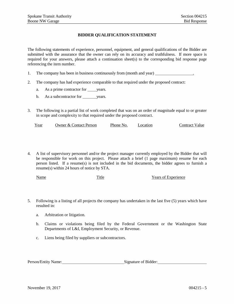
BIDDER QUALIFICATION STATEMENT
The following statements of experience, personnel, equipment, and general qualifications of the Bidder are submitted with the assurance that the owner can rely on its accuracy and truthfulness. If more space is required for your answers, please attach a continuation sheet(s) to the corresponding bid response page referencing the item number.
1. The company has been in business continuously from (month and year) .
2. The company has had experience comparable to that required under the proposed contract:
a. As a prime contractor for years.
b. As a subcontractor for years.
3. The following is a partial list of work completed that was on an order of magnitude equal to or greater in scope and complexity to that required under the proposed contract.
Year Owner & Contact Person Phone No. Location Contract Value
4. A list of supervisory personnel and/or the project manager currently employed by the Bidder that will be responsible for work on this project. Please attach a brief (1 page maximum) resume for each person listed. If a resume(s) is not included in the bid documents, the bidder agrees to furnish a resume(s) within 24 hours of notice by STA.
Name Title Years of Experience
5. Following is a listing of all projects the company has undertaken in the last five (5) years which have resulted in:
a. Arbitration or litigation.
b. Claims or violations being filed by the Federal Government or the Washington State Departments of L&I, Employment Security, or Revenue.
c. Liens being filed by suppliers or subcontractors.
Person/Entity Name: Signature of Bidder:
Spokane Transit Authority Section 004215 Boone NW Garage Bid Response
November 19, 2017 004215 - 6
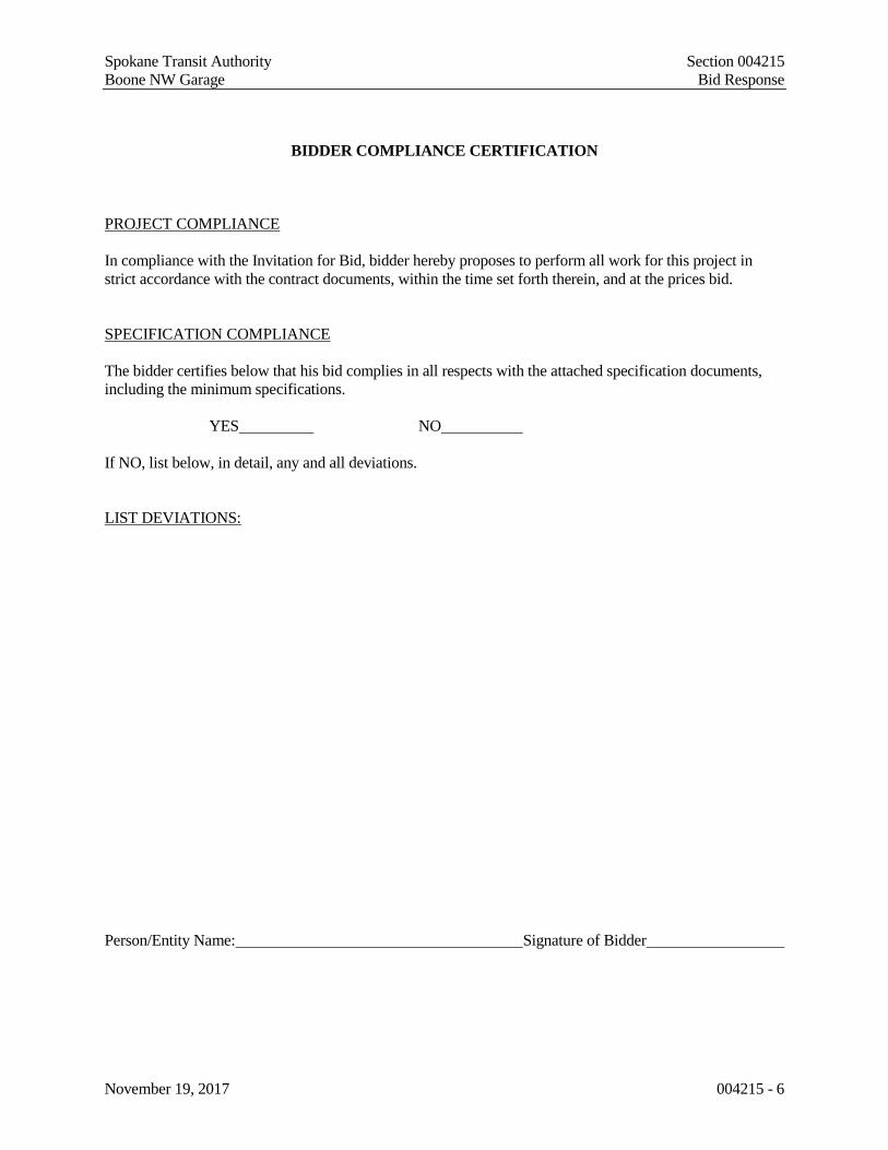
BIDDER COMPLIANCE CERTIFICATION
PROJECT COMPLIANCE In compliance with the Invitation for Bid, bidder hereby proposes to perform all work for this project in strict accordance with the contract documents, within the time set forth therein, and at the prices bid. SPECIFICATION COMPLIANCE The bidder certifies below that his bid complies in all respects with the attached specification documents, including the minimum specifications. YES NO If NO, list below, in detail, any and all deviations. LIST DEVIATIONS: Person/Entity Name: Signature of Bidder

Spokane Transit Authority Section 004215 Boone NW Garage Bid Response
November 19, 2017 004215 - 7
SUBCONTRACTOR LIST
Project Number: 17-STA-579 The Bidder will provide a list of all subcontractors anticipated to be used on this project. Use a copy of this page as a master for attachment if necessary. If no subcontractors are listed, it will be considered the bidder’s affirmation that it does not intend to use any subcontractors on this project. Type of work - Name of Firm (please print): (as registered with the State of Washington) Physical Address: City, State, Zip: Telephone/Fax Numbers: Washington State Contractors Registration Number: Washington State Electrical or Plumbers License Number: Federal Tax Identification Number: Washington State UBI Number: State Industrial Account Identification Number: **Note: If a corporation, write State of Incorporation under signature. If a partnership, give full names of all partners. Person/Entity Name: Signature of Bidder

Spokane Transit Authority Section 004215 Boone NW Garage Bid Response
November 19, 2017 004215 - 8
DETAILED WORK PLAN
Boone NW Garage
Upon Receipt of Notice to Proceed: *Reference: Bid Checklist “Work Plan” parts (a.) through (d.). Person/Entity Name: Signature of Bidder END OF SECTION 004215

Spokane Transit Authority Section 004512 Boone NW Garage Responsibility Criteria
November 19, 2017 004512 - 1
SECTION 004512 – RESPONSIBILITY CRITERIA RESPONSIBILITY CRITERIA – Boone NW Garage In accordance with RCW 39.04, before award of a public works contract, a Bidder must meet the following responsibility criteria to be considered a responsible bidder and qualified to be awarded a public works project. The Bidder must: 1. At the time of bid submittal, have a certificate of registration in compliance with chapter 18.27 RCW; 2. Have a current state unified business identifier (UBI) number; 3. If applicable, have industrial insurance coverage for the Bidder’s employees working in Washington as
required in Title 51 RCW; 4. If applicable, have an employment security department number as required in Title 50 RCW; 5. If applicable, have a state excise tax registration number as required in Title 82 RCW; and 6. Not be disqualified from bidding on any public works contract under RCW 39.06.010 or 39.12.065(3). In accordance with RCW 39.06, a public works contractor must verify responsibility criteria for each first tier subcontractor, and a subcontractor of any tier that hires other subcontractors must verify responsibility criteria for each of its subcontractors. Verification shall include that each subcontractor, at the time of subcontract execution, meets the responsibility criteria and possesses an electrical contractor license, if required by RCW 19.28, or an elevator contractor license, if required by RCW 70.87. This verification requirement, as well as the responsibility criteria, must be included in every public works contract and subcontract of every tier. Providing the following information is MANDATORY in order to meet “Responsible Bidder” requirements. Failure to provide this information may disqualify your bid as being “Non-Responsive”. If your business is not required to have one of the following numbers, provide an explanation.
1. State of Washington Contractor Registration No.
2. State of Washington Unified Business Identifier No.
3. Employment Security Department No.
4. State Excise Tax Registration No.
5. Is the payment of Worker’s Comp (Industrial Insurance) Premiums current? If your business does not have a Worker’s Comp account with the WA State Dept of L&I, please explain why.
[ ] Yes
[ ] No (If No, you are not eligible to bid on this project)
[ ] No Account – Explain why:
6. Are you disqualified from bidding on public works projects in the State of Washington?
[ ] Yes (If Yes, you are not eligible to bid on this project)
[ ] No
END OF SECTION 004512

Spokane Transit Authority Section 004512 Boone NW Garage Responsibility Criteria
November 19, 2017 004512 - 2
THIS PAGE INTENTIONALLY LEFT BLANK

Spokane Transit Authority Section 004546.C Boone NW Garage Disadvantaged Business Enterprise (DBE) Participation
November 19, 2017 004546.C - 1
SECTION 004546.C – DISADVANTAGED BUSINESS ENTERPRISE (DBE) PARTICIPATION DBE Participation: STA is committed to ensuring that all firms regardless of race, color, creed, national origin, sex, sexual orientation, gender identity, or presence of any sensory, mental or physical disability have equal opportunity to participate in STA contracts. Therefore, STA has established an annual agency goal for DBE participation in its contracting opportunities. It shall be understood that no specific goal has been assigned to this contract; however, contractors and subcontractors are required to comply with the following: Non-Discrimination Assurances: The contract or subcontractor shall not discriminate on the basis of race, color, national origin, or sex in the performance of this contract. The contractor shall carry out applicable requirements of 49 CFR part 26 in the award and administration of DOT-assisted contracts. Failure by the contractor to carry out these requirements is a material breach of this contract, which may result in the termination of this contract or other such remedy, as STA deems appropriate. A copy of 49 CFR part 26 may be obtained by contacting STA’s DBE Liaison, Spokane Transit Authority,1230 W. Boone, Spokane, WA 99201, (509) 325-6032. Prompt Payment: The contractor agrees to pay each subcontractor under this prime contract for satisfactory performance of its contract no later than thirty days from the receipt of each payment the prime contractor receives from STA. The prime contractor agrees further to return retainage payments to each subcontractor within thirty days after the subcontractor’s work is satisfactorily completed. Any delay or postponement of payment from the above time frames may occur only for good cause following written approval of STA. This clause applies to both DBE and non-DBE subcontractors. DBE Bidders List: STA is required to create and maintain a bidders list of all firms bidding on prime contracts and bidding or quoting on subcontracts on Department of Transportation-assisted contracts. To assist STA in compliance with this provision of the regulation, please complete and return with your proposal. Instructions: 1. List the names and addresses of DBE firms that will participate in this contract; 2. A description of the work each DBE will perform; 3. The dollar amount of the participation of each DBE firm participating; Name & Address of DBE Firm Description of Work to perform $ Amount 1. 2. 3.
END OF SECTION 004546.C

Spokane Transit Authority Section 004546.C Boone NW Garage Disadvantaged Business Enterprise (DBE) Participation
November 19, 2017 004546.C - 2
THIS PAGE INTENTIONALLY LEFT BLANK

Spokane Transit Authority Section 004546.D Boone NW Garage Certification Regarding Debarment and Suspension
November 19, 2017 004546.D - 1
SECTION 004546.D – CERTIFICATION REGARDING DEBARMENT, SUSPENSION, INELIGIBILITY AND VOLUNTARY EXCLUSION IN A LOWER TIER COVERED TRANSACTION This contract is a covered transaction for purposes of 2 CFR Parts 1200 and 180. As such, the CONSULTANT or CONTRACTOR is required to comply with 2 CFR Part 180, Subpart C and must include the requirement to comply with 2 CFR Part 180, Subpart C in any lower tier covered transaction it enters into.
By signing and submitting its bid or proposal, the bidder or proposer certifies as follows:
The certification in this clause is a material representation of fact relied upon by Spokane Transit Authority. If it is later determined that the bidder or proposer knowingly rendered an erroneous certification, in addition to remedies available to Spokane Transit Authority, the Federal Government may pursue available remedies, including but not limited to suspension and/or debarment. The bidder or proposer agrees to comply with the requirements of 2 CFR Part 180, Subpart C while this offer is valid and throughout the period of any contract that may arise from this offer. The bidder or proposer further agrees to include a provision requiring such compliance in its lower tier covered transactions. Company Name or Respondent:_____________________________________________________________ Company Address: _______________________________________________________________________ Telephone Number: ______________________________________________________________________ Fax Number: ____________________________________________________________________________ Email Address: __________________________________________________________________________ Authorized Signature: _____________________________________________________________________ Printed Name and Title: ___________________________________________________________________ Date Signed: ____________________________________________________________________________
END OF SECTION 004546.D

Spokane Transit Authority Section 004546.D Boone NW Garage Certification Regarding Debarment and Suspension
November 19, 2017 004546.D - 2
THIS PAGE INTENTIONALLY LEFT BLANK

Spokane Transit Authority Section 004546.E Boone NW Garage Certification of Compliance with Wage Payment Statutes
November 19, 2017 004546.E - 1
SECTION 004546.E – CERTIFICATION OF COMPLIANCE WITH WAGE PAYMENT STATUTES
The bidder hereby certifies that, within the three-year period immediately preceding the bid solicitation date (August 16, 2017), the bidder is not a “willful” violator, as defined in RCW 49.48.082, of any provision of chapters 49.46, 49.48, or 49.52 RCW, as determined by a final and binding citation and notice of assessment issued by the Department of Labor and Industries or through a civil judgment entered by a court of limited or general jurisdiction. I certify under penalty of perjury under the laws of the State of Washington that the foregoing is true and correct. Bidder’s Business Name Signature of Authorized Official* Printed Name Title Date
City
State
Check One: Sole Proprietorship ☐ Partnership ☐ Joint Venture ☐ Corporation ☐ State of Incorporation, or if not a corporation, State where business entity was formed:
If a co-partnership, give firm name under which business is transacted:
* If a corporation, proposal must be executed in the corporate name by the president or vice-president (or any other corporate officer accompanied by evidence of authority to sign). If a co-partnership, proposal must be executed by a partner.
END OF SECTION 004546.E

Spokane Transit Authority Section 004546.E Boone NW Garage Certification of Compliance with Wage Payment Statutes
November 19, 2017 004546.E - 2
THIS PAGE INTENTIONALLY LEFT BLANK
Spokane Transit Authority Section 005200 Boone NW Garage STA Form of Contract Between Owner and Contractor
November 19, 2017 005200 - 1
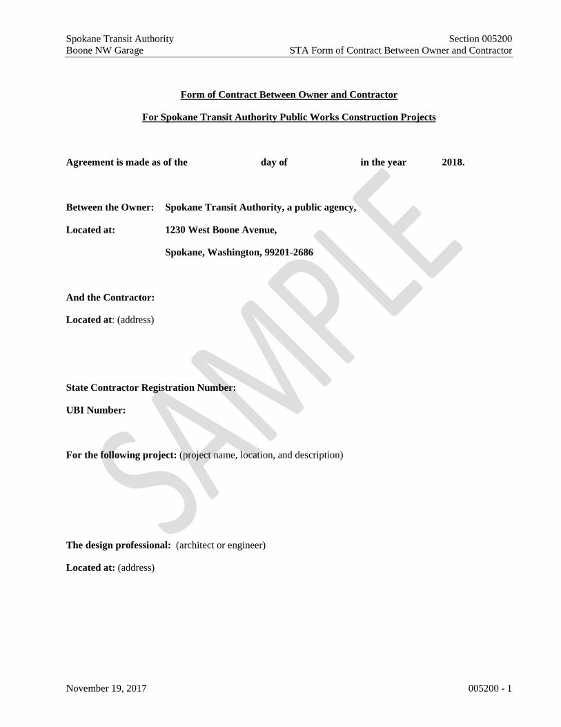
Form of Contract Between Owner and Contractor
For Spokane Transit Authority Public Works Construction Projects
Agreement is made as of the day of in the year 2018.
Between the Owner: Spokane Transit Authority, a public agency,
Located at: 1230 West Boone Avenue,
Spokane, Washington, 99201-2686
And the Contractor:
Located at: (address)
State Contractor Registration Number:
UBI Number:
For the following project: (project name, location, and description)
The design professional: (architect or engineer)
Located at: (address)

Spokane Transit Authority Section 005200 Boone NW Garage STA Form of Contract Between Owner and Contractor
November 19, 2017 005200 - 2
The owner and contractor agree as follows:
1. The Contract Documents include: A. This agreement signed by the Owner and the Contractor B. The Advertisement for Bids and all Bid Documents C. The General Conditions, Supplemental Conditions [and Special Conditions] D. The drawings and specifications prepared by the design professional
(list the drawing number range from page 1 to ___ and the date[s] (list the specifications number range from page 1 to ___ and the date)
E. The Invitation for Bid (IFB) F. The addenda: (list any/all addenda by number, date and quantity of pages)
Number Date Quantity of pages
G. Changes in the work issued after execution of the agreement H. Other documents identified as follows:

Spokane Transit Authority Section 005200 Boone NW Garage STA Form of Contract Between Owner and Contractor
November 19, 2017 005200 - 3
2. Contract sum: (list base individually the bid amount plus any/all alternates taken)
3. Unit prices: (list items by description, the units and limits and the price per unit)
Item(s) Units/limits Price per unit
4. Allowances included in contract sum: (list any allowances included in the contract sum) Item Price
5. Other terms or conditions not otherwise covered in the noted previous documents.

Spokane Transit Authority Section 005200 Boone NW Garage STA Form of Contract Between Owner and Contractor
November 19, 2017 005200 - 4
6. In cases where communication is required between the Contractor and STA, such as further information, furnishing of specifications, or obtaining approval of proposed work, such communications from the Contractor shall be forwarded directly to:
Jessica Charlton Project Manager Spokane Transit Authority 1230 W. Boone Ave. Spokane, WA 99201 (509) 325-6049
7. If any provision of this contract is held invalid, the remainder of this contract shall not be affected thereby, if such remainder would then continue to conform to the terms and requirements of applicable law.
8. This Agreement may be executed in one or more counterparts, each of which shall constitute an original Agreement but all of which together shall constitute one and the same instrument.
Owner: Contractor:
_______________________________________ ________________________________________ (signature and title of authorized agent) (signature and title of authorized agent)
_______________________________________ ________________________________________ (printed name) (printed name)
_______________________________________ ________________________________________ (title) (title)

Spokane Transit Authority Section 007200.1 Boone NW Garage General Conditions for STA Facility Construction
November 19, 2017 007200.1 - 1
Section 07200.1 – General Conditions for Spokane Transit Authority Facility Construction Contract # 17-STA-579 The following is adopted and incorporated as STA General Conditions applicable to facilities construction. Although these conditions are organized consistent with the General Conditions for Washington State Facility Construction, the provisions herein are not identical to the Washington State provisions. Please review these General Conditions carefully.
TABLE OF CONTENTS Page
Part 1 - GENERAL PROVISIONS ..................................... 1 1.01 DEFINITIONS ....................................................2 1.02 ORDER OF PRECEDENCE ..............................3 1.03 EXECUTION AND INTENT .............................3 Part 2 - INSURANCE AND BONDS ................................. 4 2.01 CONTRACTOR’S LIABILITY
INSURANCE ......................................................4 2.02 COVERAGE LIMITS.........................................4 2.03 INSURANCE COVERAGE
CERTIFICATES .................................................4 2.04 PAYMENT AND PERFORMANCE
BONDS ...............................................................4 2.05 ALTERNATIVE SURETY ................................5 2.06 BUILDER’S RISK ..............................................5 Part 3 - TIME AND SCHEDULE....................................... 5 3.01 PROGRESS AND COMPLETION ....................5 3.02 CONSTRUCTION SCHEDULE ........................5 3.03 OWNER’S RIGHT TO SUSPEND THE
WORK FOR CONVENIENCE ..........................6 3.04 OWNER’S RIGHT TO STOP THE
WORK FOR CAUSE..........................................7 3.05 DELAY ...............................................................7 3.06 NOTICE TO OWNER OF LABOR
DISPUTES ..........................................................8 3.07 DAMAGES FOR FAILURE TO
ACHIEVE TIMELY COMPLETION.................8 Part 4 - SPECIFICATIONS, DRAWINGS, AND
OTHER DOCUMENTS ..................................... 8 4.01 DISCREPANCIES AND CONTRACT
DOCUMENT REVIEW .....................................9 4.02 PROJECT RECORD ..........................................9 4.03 SHOP DRAWINGS ............................................9 4.04 ORGANIZATION OF SPECIFICATIONS ...... 10 4.05 OWNERSHIP AND USE OF
DRAWINGS, SPECIFICATIONS, AND OTHER DOCUMENTS ................................... 10
Part 5 - PERFORMANCE ................................................ 11 5.01 CONTRACTOR CONTROL AND
SUPERVISION ................................................ 11 5.02 PERMITS, FEES, AND NOTICES .................. 12 5.03 PATENTS AND ROYALTIES ........................ 12 5.04 PREVAILING WAGES ................................... 12 5.05 HOURS OF LABOR ........................................ 13 5.06 NONDISCRIMINATION ................................. 13 5.07 SAFETY PRECAUTIONS ............................... 14
5.08 OPERATIONS, MATERIAL HANDLING, AND STORAGE AREAS ......... 15
5.09 PRIOR NOTICE OF EXCAVATION .............. 16 5.10 UNFORESEEN PHYSICAL
CONDITIONS.................................................. 16 5.11 PROTECTION OF EXISTING
STRUCTURES, EQUIPMENT, VEGETATION, UTILITIES, AND IMPROVEMENTS .......................................... 16
5.12 LAYOUT OF WORK ...................................... 16 5.13 MATERIAL AND EQUIPMENT .................... 16 5.14 AVAILABILITY AND USE OF
PREMISES AND UTILITY SERVICES ......... 17 5.15 TESTS AND INSPECTION ............................ 17 5.16 CORRECTION OF NONCONFORMING
WORK .............................................................. 18 5.17 CLEAN UP ...................................................... 19 5.18 ACCESS TO WORK AND
COMMUNICATIONS REGARDING PROJECT STATUS ......................................... 19
5.19 OTHER CONTRACTS .................................... 20 5.20 SUBCONTRACTORS AND SUPPLIERS ...... 20 5.21 WARRANTY OF CONSTRUCTION ............. 21 5.22 INDEMNIFICATION ...................................... 21 Part 6 - PAYMENTS AND COMPLETION .................... 22 6.01 CONTRACT SUM ........................................... 22 6.02 SCHEDULE OF VALUES .............................. 22 6.03 APPLICATION FOR PAYMENT ................... 22 6.04 PROGRESS PAYMENTS ............................... 23 6.05 PAYMENTS WITHHELD............................... 24 6.06 RETAINAGE AND BOND CLAIM
RIGHTS ........................................................... 24 6.07 SUBSTANTIAL COMPLETION .................... 24 6.08 PRIOR OCCUPANCY ..................................... 24 6.09 FINAL INSPECTION, FINAL
COMPLETION, ACCEPTANCE, AND PAYMENT (PROJECT CLOSE-OUT) ........... 25
Part 7 - CHANGES .......................................................... 26 7.01 CHANGE IN THE WORK .............................. 26 7.02 CHANGE IN THE CONTRACT SUM............ 27 7.03 CHANGE IN THE CONTRACT TIME .......... 34 Part 8 - CLAIMS AND DISPUTE RESOLUTION ......... 36 8.01 CLAIMS 8.02 ARBITRATION 8.03 CLAIMS AUDITS ........................................... 38 Part 9 - TERMINATION OF THE WORK ...................... 39 9.01 TERMINATION BY OWNER FOR
CAUSE ............................................................. 39 9.02 TERMINATION BY OWNER FOR
CONVENIENCE .............................................. 40 Part 10 MISCELLANEOUS PROVISIONS .................... 41 10.01 GOVERNING LAW ........................................ 41 10.02 SUCCESSORS AND ASSIGNS ...................... 41 10.03 MEANING OF WORDS .................................. 41 10.04 RIGHTS AND REMEDIES ............................. 41 10.05 CONTRACTOR REGISTRATION ................. 41 10.06 TIME COMPUTATIONS ................................ 41 10.07 RECORDS RETENTION ................................ 41 10.08 THIRD-PARTY AGREEMENTS .................... 41 10.09 ANTITRUST ASSIGNMENT ......................... 41 PART 1- GENERAL PROVISIONS

Spokane Transit Authority Section 007200.1 Boone NW Garage General Conditions for STA Facility Construction
November 19, 2017 007200.1 - 2
1.01 DEFINITIONS
A. “Application for Payment” means a written request submitted by Contractor to Owner or, if applicable, A/E for payment of Work completed in accordance with the Contract Documents and approved Schedule of Values, supported by such substantiating data as Owner or, if applicable, A/E may require.
B. “Architect,” “Engineer,” or “A/E” means a person or entity lawfully entitled to practice architecture or engineering, representing Owner within the limits of its delegated authority.
C. “Award” means the formal decision by the Owner notifying a responsible Bidder with the lowest responsive bid of the Owner’s acceptance of the bid and intent to enter into a contract with the Bidder.
D. “Change Order” means a written instrument signed by Owner and Contractor stating their agreement upon all of the following: (1) a change in the Work; (2) the amount of the adjustment in the Contract Sum, if any, and (3) the extent of the adjustment in the Contract Time, if any.
E. “Claim” means Contractor’s exclusive remedy for resolving disputes with Owner regarding the terms of a Change Order or a request for equitable adjustment, as more fully set forth in Part 8.
F. “Contract Award Amount” is the sum of the Base Bid and any accepted Alternates.
G. “Contract Documents” means the Advertisement for Bids, Instructions for Bidders, completed Bid Form, General Conditions, Modifications to the General Conditions, Supplemental Conditions, Special Conditions, Contract, other Special Forms, Drawings and Specifications, and all addenda and modifications thereof.
H. “Contract Sum” is the total amount payable by Owner to Contractor for performance of the Work in accordance with the Contract Document. Except as described below, the Contract Sum includes all taxes imposed by law and properly chargeable to the Work. The Contract Sum does not include Washington State sales tax.
I. “Contract Time” is the number of calendar days allotted in the Contract Documents for achieving Substantial Completion of the Work.
J. “Contractor” means the person or entity who has agreed with Owner to perform the Work in accordance with the Contract Documents. Contractor’s duties and obligations flow down and become duties and obligations of Subcontractors.
K. “Day(s)”: Unless otherwise specified, day(s) shall mean calendar day(s).
L. “Drawings” are the graphic and pictorial portions of the Contract Documents showing the design, location, and dimensions of the Work, and may include plans, elevations, sections, details, schedules, and diagrams.
M. “Final Acceptance” means the written acceptance issued to Contractor by Owner after Contractor has completed the requirements of the Contract Documents, as more fully set forth in Section 6.09E.
N. “Final Completion” means that the Work is fully and finally complete in accordance with the Contract Documents, as more fully set forth in Section 6.09D.
O. “Force Majeure” means those acts entitling Contractor to request an equitable adjustment in the Contract Time, as more fully set forth in Section 3.05A.
P. “Notice” means a written notice which has been delivered in person to the individual or a member of the firm or entity or to an officer of the corporation for which it was intended or, if delivered or sent by registered or certified mail, to the last business address known to the party giving notice.
Q. ‘‘Notice to Proceed” means a notice from Owner to Contractor that defines the date on which the Contract Time begins to run.
R. “Owner” means the Spokane Transit Authority (“STA”) or its authorized representative with the authority to enter into, administer, and/or terminate the Work in accordance with the Contract Documents and make related determinations and findings.
S. “Person” means a corporation, partnership, business association of any kind, trust, company, or individual.
T. “Prior Occupancy” means Owner’s use of all or parts of the Project before Substantial Completion, as more fully set forth in Section 6.08A.
U. “Progress Schedule” means a schedule of the Work, in a form satisfactory to Owner, as further set forth in Section 3.02B.
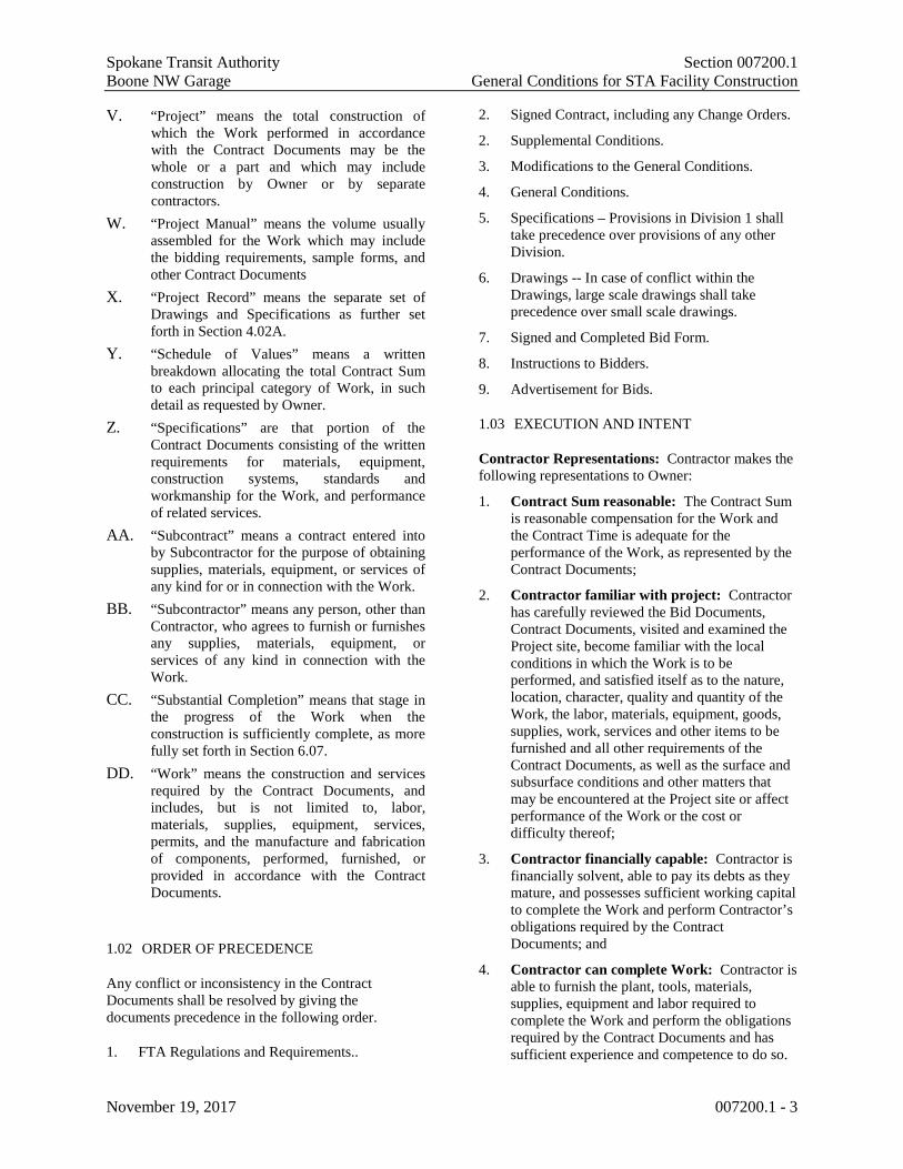
Spokane Transit Authority Section 007200.1 Boone NW Garage General Conditions for STA Facility Construction
November 19, 2017 007200.1 - 3
V. “Project” means the total construction of which the Work performed in accordance with the Contract Documents may be the whole or a part and which may include construction by Owner or by separate contractors.
W. “Project Manual” means the volume usually assembled for the Work which may include the bidding requirements, sample forms, and other Contract Documents
X. “Project Record” means the separate set of Drawings and Specifications as further set forth in Section 4.02A.
Y. “Schedule of Values” means a written breakdown allocating the total Contract Sum to each principal category of Work, in such detail as requested by Owner.
Z. “Specifications” are that portion of the Contract Documents consisting of the written requirements for materials, equipment, construction systems, standards and workmanship for the Work, and performance of related services.
AA. “Subcontract” means a contract entered into by Subcontractor for the purpose of obtaining supplies, materials, equipment, or services of any kind for or in connection with the Work.
BB. “Subcontractor” means any person, other than Contractor, who agrees to furnish or furnishes any supplies, materials, equipment, or services of any kind in connection with the Work.
CC. “Substantial Completion” means that stage in the progress of the Work when the construction is sufficiently complete, as more fully set forth in Section 6.07.
DD. “Work” means the construction and services required by the Contract Documents, and includes, but is not limited to, labor, materials, supplies, equipment, services, permits, and the manufacture and fabrication of components, performed, furnished, or provided in accordance with the Contract Documents.
1.02 ORDER OF PRECEDENCE
Any conflict or inconsistency in the Contract Documents shall be resolved by giving the documents precedence in the following order.
1. FTA Regulations and Requirements..
2. Signed Contract, including any Change Orders.
2. Supplemental Conditions.
3. Modifications to the General Conditions.
4. General Conditions.
5. Specifications – Provisions in Division 1 shall take precedence over provisions of any other Division.
6. Drawings -- In case of conflict within the Drawings, large scale drawings shall take precedence over small scale drawings.
7. Signed and Completed Bid Form.
8. Instructions to Bidders.
9. Advertisement for Bids.
1.03 EXECUTION AND INTENT
Contractor Representations: Contractor makes the following representations to Owner:
1. Contract Sum reasonable: The Contract Sum is reasonable compensation for the Work and the Contract Time is adequate for the performance of the Work, as represented by the Contract Documents;
2. Contractor familiar with project: Contractor has carefully reviewed the Bid Documents, Contract Documents, visited and examined the Project site, become familiar with the local conditions in which the Work is to be performed, and satisfied itself as to the nature, location, character, quality and quantity of the Work, the labor, materials, equipment, goods, supplies, work, services and other items to be furnished and all other requirements of the Contract Documents, as well as the surface and subsurface conditions and other matters that may be encountered at the Project site or affect performance of the Work or the cost or difficulty thereof;
3. Contractor financially capable: Contractor is financially solvent, able to pay its debts as they mature, and possesses sufficient working capital to complete the Work and perform Contractor’s obligations required by the Contract Documents; and
4. Contractor can complete Work: Contractor is able to furnish the plant, tools, materials, supplies, equipment and labor required to complete the Work and perform the obligations required by the Contract Documents and has sufficient experience and competence to do so.

Spokane Transit Authority Section 007200.1 Boone NW Garage General Conditions for STA Facility Construction
November 19, 2017 007200.1 - 4
Part 2 - INSURANCE AND BONDS
2.01 CONTRACTOR’S LIABILITY INSURANCE
General Insurance Requirements: Prior to commencement of the Work, Contractor shall obtain all the insurance required by the Contract Documents and provide evidence satisfactory to Owner that such insurance has been procured. Review of the Contractor’s insurance by Owner shall not relieve or decrease the liability of Contractor. Companies writing the insurance to be obtained by this part shall be licensed to do business under Chapter 48 RCW or comply with the Surplus Lines Law of the State of Washington. Contractor shall include in its bid the cost of all insurance and bond costs required to complete the base bid work and accepted alternates. Insurance carriers providing insurance in accordance with the Contract Documents shall be acceptable to Owner, and its A. M. Best rating shall be indicated on the insurance certificates.
A. Term of Insurance Coverage: Contractor shall maintain the following insurance coverage during the Work and for one year after Final Acceptance. Contractor shall also maintain the following insurance coverage during the performance of any corrective Work required by Section 5.16.
1. General Liability Insurance: Commercial General Liability (CGL) on an Occurrence Form. Coverage shall include, but not be limited to:
a. Completed operations/products liability;
b. Explosion, collapse*, and underground; and
c. Employer’s liability coverage.
2. Automobile Liability Insurance: Automobile liability.
B. Industrial Insurance compliance: Contractor shall comply with the Washington State Industrial Insurance Act and, if applicable, the Federal Longshoremen’s and Harbor Workers’ Act and the Jones Act.
C. Insurance to protect for the following: All insurance coverages shall protect against claims for damages for personal and bodily injury or death, as well as claims for property damage, which may arise from operations in connection with the Work whether such operations are by Contractor or any Subcontractor.
D. Owner as Additional Insured: All insurance
coverages shall be endorsed to include Owner as an additional named insured for Work performed in accordance with the Contract Documents, and all insurance certificates shall evidence the Owner as an additional insured.
2.02 COVERAGE LIMITS
Insurance Amounts: The coverage limits shall be as follows:
A. Limits of Liability shall not be less than $1,000,000 Combined Single Limit for Bodily Injury and Property Damage (other than Automobile Liability) Each Occurrence; Personal Injury and Advertising Liability Each Occurrence.
B. $2,000,000 Combined Single Limit Annual General Aggregate.
C. $2,000,000 Annual Aggregate for Products and Completed Operations Liability.
D. $1,000,000 Combined Single Limit for Automobile Bodily Injury and Property Damage Liability, Each Accident or Loss.
2.03 INSURANCE COVERAGE CERTIFICATES
A. Certificate required: Prior to commencement of the Work, Contractor shall furnish to Owner a completed certificate of insurance coverage.
B. List Project information: All insurance certificates shall name Owner’s Project number and Project title.
C. Cancellation provisions: All insurance certificates shall specifically require 45 Days prior notice to Owner of cancellation or any material change, except 30 Days for surplus line insurance.
2.04 PAYMENT AND PERFORMANCE BONDS
Conditions for bonds: Payment and performance bonds for 100% of the Contract Award Amount plus state sales tax, shall be furnished for the Work, using the Payment Bond and Performance Bond form published by and available from the American Institute of Architects (AIA) – form A312 (or current version of the same). Prior to execution of a Change Order that, cumulatively with previous Change Orders, increases the Contract Award Amount by 15% or more, the Contractor shall provide either new payment and performance bonds for the revised Contract Sum, or riders to the existing payment and performance bonds increasing the amount of the bonds. The Contractor shall likewise provide additional bonds or riders when subsequent Change

Spokane Transit Authority Section 007200.1 Boone NW Garage General Conditions for STA Facility Construction
November 19, 2017 007200.1 - 5
Orders increase the Contract Sum by 15% or more. No payment or performance bond is required if the contract Sum is $35,000 or less and Contractor agrees that Owner may, in lieu of the bond, retain 50% of the Contract Sum for the period allowed by RCW 39.08.010.
2.05 ALTERNATIVE SURETY
When alternative surety required: Contractor shall promptly furnish payment and performance bonds from an alternative surety as required to protect Owner and persons supplying labor or materials required by the Contract Documents if:
A. Owner has a reasonable objection to the surety; or
B. Any surety fails to furnish reports on its financial condition if requested by Owner.
2.06 BUILDER’S RISK
A. Contractor to buy Property Insurance: Contractor shall purchase and maintain property insurance in the amount of the Contract Sum including all Change Orders for the Work on a replacement cost basis until Substantial Completion. For projects not involving New Building Construction, “Installation Floater” is an acceptable substitute for the Builder’s Risk Insurance. The insurance shall cover the interest of Owner, Contractor, and any Subcontractors, as their interests may appear.
B. Losses covered: Contractor property insurance shall be placed on an “all risk” basis and insure against the perils of fire and extended coverage and physical loss or damage including theft, vandalism, malicious mischief, collapse, false work, temporary buildings, debris removal including demolition occasioned by enforcement of any applicable legal requirements, and shall cover reasonable compensation for Owner’s and, if applicable, A/E’s services and expenses required as a result of an insured loss.
C. Waiver of subrogation rights: Owner and Contractor waive all subrogation rights against each other, any Subcontractors, A/E, A/E’s subconsultants, separate contractors, if any, and any of their subcontractors, for damages caused by fire or other perils to the extent covered by property insurance obtained pursuant to this section or other property insurance applicable to the Work, except such rights as they have to proceeds of such insurance held by Owner as fiduciary. The policies shall provide such waivers of subrogation by endorsement or
otherwise. A waiver of subrogation shall be effective to a person or entity even though that person or entity would otherwise have a duty of indemnification, contractual or otherwise, did not pay the insurance premium directly or indirectly, and whether or not the person or entity had an insurable interest in the property damaged.
Part 3 - TIME AND SCHEDULE
3.01 PROGRESS AND COMPLETION
Contractor to meet schedule: Contractor shall diligently prosecute the Work, with adequate forces, achieve Substantial Completion within the Contract Time, and achieve Final Completion within a reasonable period thereafter.
3.02 CONSTRUCTION SCHEDULE
A. Preliminary Progress Schedule: Unless otherwise provided in the Contract, supplemental conditions, or modifications to these General Conditions, Contractor shall, within 14 Days after issuance of the Notice to Proceed, submit a preliminary Progress Schedule. The Progress Schedule shall show the sequence in which Contractor proposes to perform the Work, and the dates on which Contractor plans to start and finish major portions of the Work, including dates for shop drawings and other submittals, and for acquiring materials and equipment.
B. Form of Progress Schedule: The Progress Schedule shall be created, maintained and edited using MS Project software or similar software identified and agreed to by and between the parties. The scheduling of construction is the responsibility of the Contractor and is included in the contract to assure adequate planning and execution of the work. The schedule will be used to evaluate progress of the work for payment based on the Schedule of Values. The schedule shall show the Contractor’s planned order and interdependence of activities, and sequence of work. As a minimum the schedule shall include:
• Date of Notice to Proceed;
• Activities (resources, durations, individual responsible for activity, early starts, late starts, early finishes, late finishes, etc.);
• Utility Shutdowns;

Spokane Transit Authority Section 007200.1 Boone NW Garage General Conditions for STA Facility Construction
November 19, 2017 007200.1 - 6
• Interrelationships and dependence of activities;
• Planned vs. actual status for each activity;
• Substantial completion;
• Punch list;
• Final inspection;
• Final completion, and
• Float time
The Schedule Duration shall be based on the Contract Time of Completion listed on the Bid Proposal form. The Owner shall not be obligated to accept any Early Completion Schedule suggested by the Contractor. The Contract Time for Completion shall establish the Schedule Completion Date.
If the Contractor feels that the work can be completed in less than the Specified Contract Time, then the Surplus Time shall be considered Project Float. This Float time shall be shown on the Project Schedule. It shall be available to accommodate changes in the work and unforeseen conditions.
Neither the Contractor nor the Owner have exclusive right to this Float Time. It belongs to the project.
C. Owner comments on Progress Schedule: Owner shall return comments on the preliminary Progress Schedule to Contractor within 14 Days of receipt. Review by Owner of Contractor’s schedule does not constitute an approval or acceptance of Contractor’s construction means, methods, or sequencing, or its ability to complete the Work within the Contract Time. Contractor shall revise and resubmit its schedule, as necessary. Owner may withhold a portion of progress payments until a Progress Schedule has been submitted which meets the requirements of this section.
D. Monthly updates and compliance with Progress Schedule: Contractor shall utilize and comply with the Progress Schedule. On a monthly basis, or as otherwise directed by Owner, Contractor shall submit an updated Progress Schedule at its own expense to Owner indicating actual progress. If, in the opinion of Owner, Contractor is not in conformance with the Progress Schedule for reasons other than acts of Force Majeure as identified in Section 3.05, Contractor shall take such steps as
are necessary to bring the actual completion dates of its work activities into conformance with the Progress Schedule, and if directed by Owner, Contractor shall submit a corrective action plan or revise the Progress Schedule to reconcile with the actual progress of the Work.
E. Contractor to notify Owner of delays: Contractor shall promptly notify Owner in writing of any actual or anticipated event which is delaying or could delay achievement of any milestone or performance of any critical path activity of the Work. Contractor shall indicate the expected duration of the delay, the anticipated effect of the delay on the Progress Schedule, and the action being or to be taken to correct the problem. Provision of such notice does not relieve Contractor of its obligation to complete the Work within the Contract Time.
3.03 OWNER’S RIGHT TO SUSPEND THE WORK FOR CONVENIENCE
A. Owner may suspend Work: Owner may, at its sole discretion, order Contractor, in writing, to suspend all or any part of the Work for up to 90 Days, or for such longer period as mutually agreed.
B. Compliance with suspension; Owner’s options: Upon receipt of a written notice suspending the Work, Contractor shall immediately comply with its terms and take all reasonable steps to minimize the incurrence of cost of performance directly attributable to such suspension. Within a period up to 90 Days after the notice is delivered to Contractor, or within any extension of that period to which the parties shall have agreed, Owner shall either:
1. Cancel the written notice suspending the Work; or
2. Terminate the Work covered by the notice as provided in the termination provisions of Part 9.
C. Resumption of Work: If a written notice suspending the Work is cancelled or the period of the notice or any extension thereof expires, Contractor shall resume Work.
D. Equitable Adjustment for suspensions: Contractor shall be entitled to an equitable adjustment in the Contract Time, or Contract Sum, or both, for increases in the time or cost of performance directly attributable to such suspension, provided Contractor complies with all requirements set forth in Part 7.

Spokane Transit Authority Section 007200.1 Boone NW Garage General Conditions for STA Facility Construction
November 19, 2017 007200.1 - 7
3.04 OWNER’S RIGHT TO STOP THE WORK FOR CAUSE
A. Owner may stop Work for Contractor’s failure to perform: If Contractor fails or refuses to perform its obligations in accordance with the Contract Documents, Owner may order Contractor, in writing, to stop the Work, or any portion thereof, until satisfactory corrective action has been taken.
B. No Equitable Adjustment for Contractor’s failure to perform: Contractor shall not be entitled to an equitable adjustment in the Contract Time or Contract Sum for any increased cost or time of performance attributable to Contractor’s failure or refusal to perform or from any reasonable remedial action taken by Owner based upon such failure.
C. Opportunity to Cure: STA in its sole discretion may, in the case of termination for breach or default, allow the Contractor an appropriate period of time, as determined by STA, in which to cure the defect of goods or service. In such case, the notice of termination will state the nature of the breach or default, the time period in which cure is permitted and other appropriate conditions. If the Contractor fails to remedy to STA’s satisfaction the breach or default of any of the terms, covenants, or conditions of this contract within the stated period of time for remedy, STA shall have the right to terminate the contract without any further obligation to the Contractor. Any such termination for default shall not in any way operate to preclude STA from also pursuing all available legal remedies against the Contractor and its sureties for said breach or default.
D. Waiver of Remedies for any Breach. In the event that STA elects to waive its remedies for any breach by the Contractor of any covenant, term or condition of this contract, such waiver by STA shall not limit STA’s legal remedies for any succeeding breach of that or of any other term, covenant, or condition of this contract.
3.05 DELAY
A. Force Majeure actions not a default; Force Majeure defined: Any delay in or failure of performance by Owner or Contractor, other than the payment of money, shall not constitute a default hereunder if and to the extent the cause for such delay or failure of performance was unforeseeable and beyond the control of the party (“Force Majeure”). Acts of Force Majeure include, but are not limited to:
1. Acts of God or the public enemy;
2. Acts or omissions of any government entity;
3. Fire or other casualty for which Contractor is not responsible;
4. Quarantine or epidemic;
5. Strike or defensive lockout;
6. Unusually severe weather, in excess of weather conditions experienced within the area any time in the preceding ten years:
a. Monthly rainfall in excess of the highest monthly rainfall experienced for the same month.
b. Annual rainfall in excess of the highest annual rainfall experienced.
c. Monthly snowfall in excess of the highest monthly snowfall experienced for the same month.
d. Annual snowfall in excess of the highest annual snowfall experienced.
e. Average high temperatures, for the summer months, in excess of the highest temperatures experienced.
f. Average low temperatures for the winter months, lower than the lowest average temperatures experienced.
7. Unusual delay in receipt of supplies or products which were ordered and expedited and for which no substitute reasonably acceptable to Owner was available.
B. Contract Time adjustment for Force Majeure: Contractor shall be entitled to an equitable adjustment in the Contract Time for changes in the time of performance directly attributable to an act of Force Majeure, provided it makes a request for equitable adjustment according to Section 7.03. Contractor shall not be entitled to an adjustment in the Contract Sum resulting from an act of Force Majeure.
C. Contract Time or Contract Sum adjustment if Owner at fault: STA reserves the right, in its sole discretion, to extend the time for
Spokane Transit Authority Section 007200.1 Boone NW Garage General Conditions for STA Facility Construction
November 19, 2017 007200.1 - 8
performance of the services contemplated by this Agreement.
D. No Contract Time or Contract Sum adjustment if Contractor at fault: Contractor shall not be entitled to an adjustment in Contract Time or in the Contract Sum for any delay or failure of performance to the extent such delay or failure was caused by Contractor or anyone for whose acts Contractor is responsible.
E. Contract Time adjustment only for concurrent fault: To the extent any delay or failure of performance was concurrently caused by the Owner and Contractor, Contractor shall be entitled to an adjustment in the Contract Time for that portion of the delay or failure of performance that was concurrently caused, provided it makes a request for equitable adjustment according to Section 7.03, but shall not be entitled to an adjustment in Contract Sum.
F. Contractor to mitigate delay impacts: Contractor shall make all reasonable efforts to prevent and mitigate the effects of any delay, whether occasioned by an act of Force Majeure or otherwise.
3.06 NOTICE TO OWNER OF LABOR DISPUTES
A. Contractor to notify Owner of labor disputes: If Contractor has knowledge that any actual or potential labor dispute is delaying or threatens to delay timely performance in accordance with the Contract Documents, Contractor shall immediately give notice, including all relevant information, to Owner.
B. Pass through notification provisions to Subcontractors: Contractor agrees to insert a provision in its Subcontracts and to require insertion in all sub-subcontracts, that in the event timely performance of any such contract is delayed or threatened by delay by any actual or potential labor dispute, the Subcontractor or Sub-subcontractor shall immediately notify the next higher tier Subcontractor or Contractor, as the case may be, of all relevant information concerning the dispute.
3.07 DAMAGES FOR FAILURE TO ACHIEVE TIMELY COMPLETION
A. Liquidated Damages
1. Reason for Liquidated Damages: Timely performance and completion
of the Work is essential to Owner and time limits stated in the Contract Documents are of the essence. Owner will incur serious and substantial damages if Substantial Completion of the Work does not occur within the Contract Time. However, it would be difficult if not impossible to determine the exact amount of such damages. Consequently, provisions for liquidated damages are included in the Contract Documents.
2. Calculation of Liquidated Damages amount: The liquidated damage amounts set forth in the Contract Documents will be assessed not as a penalty, but as liquidated damages for breach of the Contract Documents. This amount is fixed and agreed upon by and between the Contractor and Owner because of the impracticability and extreme difficulty of fixing and ascertaining the actual damages the Owner would in such event sustain. This amount shall be construed as the actual amount of damages sustained by the Owner, and may be retained by the Owner and deducted from periodic payments to the Contractor.
3. Contractor responsible even if Liquidated Damages assessed: Assessment of liquidated damages shall not release Contractor from any further obligations or liabilities pursuant to the Contract Documents.
B. Actual Damages
Calculation of Actual Damages: Actual damages will be assessed for failure to achieve Final Completion within the time provided. Actual damages will be calculated on the basis of direct architectural, administrative, and other related costs attributable to the Project from the date when Final Completion should have been achieved, based on the date Substantial Completion is actually achieved, to the date Final Completion is actually achieved. Owner may offset these costs against any payment due Contractor.
Part 4 - SPECIFICATIONS, DRAWINGS, AND OTHER DOCUMENTS

Spokane Transit Authority Section 007200.1 Boone NW Garage General Conditions for STA Facility Construction
November 19, 2017 007200.1 - 9
4.01 DISCREPANCIES AND CONTRACT DOCUMENT REVIEW
A. Specifications and Drawings are basis of the Work: The intent of the Specifications and Drawings is to describe a complete Project to be constructed in accordance with the Contract Documents. Contractor shall furnish all labor, materials, equipment, tools, transportation, permits, and supplies, and perform the Work required in accordance with the Drawings, Specifications, and other provisions of the Contract Documents.
B. Parts of the Contract Documents are complementary: The Contract Documents are complementary. What is required by one part of the Contract Documents shall be binding as if required by all. Anything mentioned in the Specifications and not shown on the Drawings, or shown on the Drawings and not mentioned in the Specifications, shall be of like effect as if shown or mentioned in both.
C. Contractor to report discrepancies in Contract Documents: Contractor shall carefully study and compare the Contract Documents with each other and with information furnished by Owner. If, during the performance of the Work, Contractor finds a conflict, error, inconsistency, or omission in the Contract Documents, it shall promptly and before proceeding with the Work affected thereby, report such conflict, error, inconsistency, or omission to Owner and, if applicable, A/E in writing.
D. Contractor knowledge of discrepancy in documents – responsibility: Contractor shall do no Work without applicable Drawings, Specifications, or written modifications, or Shop Drawings where required, unless instructed to do so in writing by Owner. If Contractor performs any construction activity, and it knows or reasonably should have known that any of the Contract Documents contain a conflict, error, inconsistency, or omission, Contractor shall be responsible for the performance and shall bear the cost for its correction.
E. Contractor to perform Work implied by Contract Documents: Contractor shall provide any work or materials the provision of which is clearly implied and is within the scope of the Contract Documents even if the Contract Documents do not mention them specifically.
F. Interpretation questions referred to Owner: Questions regarding interpretation of the requirements of the Contract Documents shall be referred to the Owner and, if applicable, the A/E.
4.02 PROJECT RECORD
A. Contractor to maintain Project Record Drawings and Specifications: Contractor shall legibly mark in ink on a separate set of the Drawings and Specifications all actual construction, including depths of foundations, horizontal and vertical locations of internal and underground utilities and appurtenances referenced to permanent visible and accessible surface improvements, field changes of dimensions and details, actual suppliers, manufacturers and trade names, models of installed equipment, and Change Order Proposals (“COP”). This separate set of Drawings and Specifications shall be the “Project Record.”
B. Update Project Record weekly and keep on site: The Project Record shall be maintained on the project site throughout the construction and shall be clearly labeled “PROJECT RECORD.” The Project Record shall be updated at least weekly noting all changes and shall be available to Owner at all times.
C. Final Project Record to Owner before Final Acceptance: Contractor shall submit the completed and finalized Project Record to Owner prior to Final Acceptance.
4.03 SHOP DRAWINGS
A. Definition of Shop Drawings: “Shop Drawings” means documents and other information required to be submitted to Owner and by Contractor pursuant to the Contract Documents, showing in detail: the proposed fabrication and assembly of structural elements; and the installation (i.e. form, fit, and attachment details) of materials and equipment. Shop Drawings include, but are not limited to, drawings, diagrams, layouts, schematics, descriptive literature, illustrations, schedules, performance and test data, samples, and similar materials furnished by Contractor to explain in detail specific portions of the Work required by the Contract Documents. For materials and equipment to be incorporated into the Work, Contractor submittal shall include the name of the manufacturer, the model number, and other information concerning the performance,

Spokane Transit Authority Section 007200.1 Boone NW Garage General Conditions for STA Facility Construction
November 19, 2017 007200.1 - 10
capacity, nature, and rating of the item. When directed, Contractor shall submit all samples at its own expense. Owner may duplicate, use, and disclose Shop Drawings provided in accordance with the Contract Documents.
B. Approval of Shop Drawings by Contractor and Owner: Contractor shall coordinate all Shop Drawings, and review them for accuracy, completeness, and compliance with the Contract Documents and shall indicate its approval thereon as evidence of such coordination and review. Where required by law, Shop Drawings shall be stamped by an appropriate professional licensed by the state of Washington. Shop Drawings submitted to Owner without evidence of Contractor’s approval shall be returned for resubmission. Contractor shall review, approve, and submit Shop Drawings with reasonable promptness and in such sequence as to cause no delay in the Work or in the activities of Owner or separate contractors. Contractor’s submittal schedule shall allow a reasonable time for Owner and, if applicable, A/E review. Owner and, if applicable, A/E will review, approve, or take other appropriate action on the Shop Drawings. Contractor shall perform no portion of the Work requiring submittal and review of Shop Drawings until the respective submittal has been reviewed and the Owner and, if applicable, A/E has approved or taken other appropriate action. Owner and, if applicable, A/E shall respond to Shop Drawing submittals with reasonable promptness. Any Work by Contractor shall be in accordance with reviewed Shop Drawings. Submittals made by Contractor which are not required by the Contract Documents may be returned without action.
C. Contractor not relieved of responsibility when Shop Drawings approved: Approval, or other appropriate action with regard to Shop Drawings, by Owner and, if applicable, A/E shall not relieve Contractor of responsibility for any errors or omissions in such Shop Drawings, nor from responsibility for compliance with the requirements of the Contract Documents. Unless specified in the Contract Documents, review by Owner and, if applicable, A/E shall not constitute an approval of the safety precautions employed by Contractor during construction, or constitute an approval of Contractor’s means or methods of construction. If Contractor fails to obtain approval before installation, and the item or work is subsequently rejected, Contractor shall be responsible for all costs of correction.
D. Variations between Shop Drawings and Contract Drawings: If Shop Drawings show variations from the requirements of the Contract Documents, Contractor shall describe such variations in writing, separate from the Shop Drawings, at the time it submits the Shop Drawings containing such variations. If Owner and, if applicable, A/E approves any such variation, an appropriate Change Order will be issued. If the variation is minor and does not involve an adjustment in the Contract Sum or Contract Time, a Change Order need not be issued; however, the modification shall be recorded upon the Project Record.
E. Contractor to submit 5 copies of Shop Drawings: Unless otherwise provided in Division I, Contractor shall submit to Owner and, if applicable, A/E for approval 5 copies of all Shop Drawings. Unless otherwise indicated, 3 sets of all Shop Drawings shall be retained by Owner and 2 sets shall be returned to Contractor.
4.04 ORGANIZATION OF SPECIFICATIONS
Specification organization by trade: Specifications are prepared in sections which conform generally with trade practices. These sections are for Owner and Contractor convenience and shall not control Contractor in dividing the Work among the Subcontractors or in establishing the extent of the Work to be performed by any trade.
4.05 OWNERSHIP AND USE OF DRAWINGS, SPECIFICATIONS, AND OTHER DOCUMENTS
A. Owner or, if applicable, A/E, not Contractor, owns Copyright of Drawings and Specifications: The Drawings, Specifications, and other documents prepared by Owner or, if applicable, A/E (the “Preparer”) are instruments of Preparer’s service through which the Work to be executed by Contractor is described. Neither Contractor nor any Subcontractor shall own or claim a copyright in the Drawings, Specifications, and other documents prepared by Preparer, and Preparer shall be deemed the author of them and will, along with any rights of Owner, retain all common law, statutory, and other reserved rights, in addition to the copyright. All copies of these documents, except Contractor’s set, shall be returned or suitably accounted for to Owner or, if applicable, A/E, on request, upon completion of the Work.

Spokane Transit Authority Section 007200.1 Boone NW Garage General Conditions for STA Facility Construction
November 19, 2017 007200.1 - 11
B. Drawings and Specifications to be used only for this Project: The Drawings, Specifications, and other documents prepared by the Owner or, if applicable, A/E, and copies thereof furnished to Contractor, are for use solely with respect to this Project. They are not to be used by Contractor or any Subcontractor on other projects or for additions to this Project outside the scope of the Work without the specific written consent of Owner and, if applicable, A/E. Contractor and Subcontractors are granted a limited license to use and reproduce applicable portions of the Drawings, Specifications, and other documents prepared by Owner or, if applicable, A/E appropriate to and for use in the execution of their Work.
C. Shop Drawing license granted to Owner: Contractor and all Subcontractors grant a non-exclusive license to Owner, without additional cost or royalty, to use for its own purposes (including reproduction) all Shop Drawings, together with the information and diagrams contained therein, prepared by Contractor or any Subcontractor. In providing Shop Drawings, Contractor and all Subcontractors warrant that they have authority to grant to Owner a license to use the Shop Drawings, and that such license is not in violation of any copyright or other intellectual property right. Contractor agrees to defend and indemnify Owner pursuant to the indemnity provisions in Sections 5.03 and 5.22 from any violations of copyright or other intellectual property rights arising out of Owner’s use of the Shop Drawings hereunder, or to secure for Owner, at Contractor’s own cost, licenses in conformity with this section.
D. Shop Drawings to be used only for this Project: The Shop Drawings and other submittals prepared by Contractor, Subcontractors of any tier, or its or their equipment or material suppliers, and copies thereof furnished to Contractor, are for use solely with respect to this Project. They are not to be used by Contractor or any Subcontractor of any tier, or material or equipment supplier, on other projects or for additions to this Project outside the scope of the Work without the specific written consent of Owner. The Contractor, Subcontractors of any tier, and material or equipment suppliers are granted a limited license to use and reproduce applicable portions of the Shop Drawings and other submittals appropriate to and for use in the
execution of their Work under the Contract Documents.
Part 5 - PERFORMANCE
5.01 CONTRACTOR CONTROL AND SUPERVISION
A. Contractor responsible for Means and Methods of construction: Contractor shall supervise and direct the Work, using its best skill and attention, and shall perform the Work in a skillful manner. Contractor shall be solely responsible for and have control over construction means, methods, techniques, sequences, and procedures and for coordinating all portions of the Work, unless the Contract Documents give other specific instructions concerning these matters. Contractor shall disclose its means and methods of construction when requested by Owner.
B. Competent Superintendence required: Performance of the Work shall be directly supervised by a competent superintendent who has authority to act for Contractor. The superintendent must be satisfactory to the Owner and shall not be changed without the prior written consent of Owner. Owner may require Contractor to remove the superintendent from the Work or Project site, if Owner reasonably deems the superintendent incompetent, careless, or otherwise objectionable, provided Owner has first notified Contractor in writing and allowed a reasonable period for transition.
C. Contractor responsible for acts and omissions of self and agents: Contractor shall be responsible to Owner for acts and omissions of Contractor, Subcontractors, and their employees and agents.
D. Contractor to employ competent and disciplined workforce: Contractor shall enforce strict discipline and good order among all of the Contractor’s employees and other persons performing the Work. Contractor shall not permit employment of persons not skilled in tasks assigned to them. Contractor’s employees shall at all times conduct business in a manner which assures fair, equal, and nondiscriminatory treatment of all persons. Owner may, by written notice, request Contractor to remove from the Work or Project site any employee Owner reasonably deems incompetent, careless, or otherwise objectionable.

Spokane Transit Authority Section 007200.1 Boone NW Garage General Conditions for STA Facility Construction
November 19, 2017 007200.1 - 12
E. Contractor to keep project documents on site: Contractor shall keep on the Project site a copy of the Drawings, Specifications, addenda, reviewed Shop Drawings, and permits and permit drawings.
F. Contractor to comply with ethical standards: Contractor shall ensure that its owner(s) and employees, and those of its Subcontractors, comply with the Ethics in Public Service Act RCW 42.52, which, among other things, prohibits state employees from having an economic interest in any public works contract that was made by, or supervised by, that employee. Contractor shall remove, at its sole cost and expense, any of its, or its Subcontractors’, employees, if they are in violation of this act.
5.02 PERMITS, FEES, AND NOTICES
A. Contractor to obtain and pay for permits: Unless otherwise provided in the Contract Documents, Contractor shall pay for and obtain all permits, licenses, and inspections necessary for proper execution and completion of the Work. Prior to Final Acceptance, the approved, signed permits shall be delivered to Owner.
B. Allowances for permit fees: If allowances for permits or utility fees are called for in the Contract Documents and set forth in Contractor’s bid, and the actual costs of those permits or fees differ from the allowances in the Contract Documents, the difference shall be adjusted by Change Order.
C. Contractor to comply with all applicable laws: Contractor shall comply with and give notices required by all federal, state, and local laws, ordinances, rules, regulations, and lawful orders of public authorities applicable to performance of the Work.
5.03 PATENTS AND ROYALTIES
Payment, indemnification, and notice: Contractor is responsible for, and shall pay, all royalties and license fees. Contractor shall defend, indemnify, and hold Owner harmless from any costs, expenses, and liabilities arising out of the infringement by Contractor of any patent, copyright, or other intellectual property right used in the Work; however, provided that Contractor gives prompt notice, Contractor shall not be responsible for such defense or indemnity when a particular design, process, or product of a particular manufacturer or manufacturers is required by the Contract
Documents. If Contractor has reason to believe that use of the required design, process, or product constitutes an infringement of a patent or copyright, it shall promptly notify Owner of such potential infringement.
5.04 PREVAILING WAGES
A. Contractor to pay Prevailing Wages: Contractor and Subcontractors shall pay the prevailing rate of wages to all workers, laborers, or mechanics employed in the performance of any part of the Work in accordance with the Davis-Bacon and Related Acts, where applicable, RCW 39.12 and the rules and regulations of the Department of Labor and Industries. The schedule of prevailing wage rates for the locality or localities of the Work, is determined by the Industrial Statistician of the Department of Labor and Industries. It is the Contractor’s responsibility to verify the applicable prevailing wage rate.
B. Statement of Intent to Pay Prevailing Wage: Before payment is made by the Owner to the Contractor for any work performed by the Contractor and subcontractors whose work is included in the application for payment, the Contractor shall submit, or shall have previously submitted to the Owner for the Project, a Statement of Intent to Pay Prevailing Wages, approved by the Department of Labor and Industries, certifying the rate of hourly wage paid and to be paid each classification of laborers, workers, or mechanics employed upon the Work by Contractor and Subcontractors. Such rates of hourly wage shall not be less than the prevailing wage rate.
C. Affidavit of Wages Paid: Prior to release of retainage or, where applicable, bond, the Contractor shall submit to the Owner an Affidavit of Wages Paid, approved by the Department of Labor and Industries, for the Contractor and every subcontractor, of any tier, that performed work on the Project.
D. Statement with pay application; Post Statements of Intent at job site: Each Application for Payment submitted by Contractor shall state that prevailing wages have been paid in accordance with the prefiled statement(s) of intent, as approved. Copies of the approved intent statement(s) shall be posted on the job site with the address and telephone number of the Industrial Statistician of the Department of Labor and Industries where a

Spokane Transit Authority Section 007200.1 Boone NW Garage General Conditions for STA Facility Construction
November 19, 2017 007200.1 - 13
complaint or inquiry concerning prevailing wages may be made.
E. Contractor to pay for Statements of Intent and Affidavits: In compliance with chapter 296-127 WAC, Contractor shall pay to the Department of Labor and Industries the currently established fee(s) for each statement of intent and/or affidavit of wages paid submitted to the Department of Labor and Industries for certification.
F. Certified Payrolls: Consistent with WAC 296-127-320, the Contractor and any subcontractor shall submit a certified copy of payroll records if requested.
5.05 HOURS OF LABOR
A. Overtime: Contractor shall comply with all applicable provisions of RCW 49.28 and they are incorporated herein by reference. Pursuant to that statute, no laborer, worker, or mechanic employed by Contractor, any Subcontractor, or any other person performing or contracting to do the whole or any part of the Work, shall be permitted or required to work more than eight hours in any one calendar day, provided, that in cases of extraordinary emergency, such as danger to life or property, the hours of work may be extended, but in such cases the rate of pay for time employed in excess of eight hours of each calendar day shall be not less than one and one-half times the rate allowed for this same amount of time during eight hours of service.
B. 4-10 Agreements: Notwithstanding the preceding paragraph, RCW 49.28 permits a contractor or subcontractor in any public works contract subject to those provisions, to enter into an agreement with its employees in which the employees work up to ten hours in a calendar day. No such agreement may provide that the employees work ten-hour days for more than four calendar days a week. Any such agreement is subject to approval by the employees. The overtime provisions of RCW 49.28 shall not apply to the hours, up to forty hours per week, worked pursuant to any such agreement.
5.06 NONDISCRIMINATION
A. Discrimination prohibited by applicable laws: Discrimination in all phases of employment is prohibited by, among other laws and regulations, Title VI of the Civil Rights Act, Title VII of the Civil Rights Act of 1964,
the Vietnam Era Veterans Readjustment Act of 1974, Sections 503 and 504 of the Vocational Rehabilitation Act of 1973, the Equal Employment Act of 1972, the Age Discrimination Act of 1975, section 202 of the Americans with Disabilities Act of 1990, the Civil Rights Act of 1991, Presidential Executive Order 11246, Executive Order 11375, Executive Order 13672, Federal transit law at 49 U.S.C. § 5332, the Washington State Law Against Discrimination, RCW 49.60, and Gubernatorial Executive Order 85-09. These laws and regulations establish minimum requirements for affirmative action and fair employment practices which Contractor and Subcontractors must meet.
B. During performance of the Work:
1. Protected Classes: Contractor shall not discriminate against any employee or applicant for employment because of race, creed, religion, color, national origin, sex, age, marital status, sexual orientation, gender identity, or the presence of any physical, sensory, or mental disability, Vietnam era veteran status, or disabled veteran status, nor commit any other unfair practices as defined in RCW 49.60 and prohibited under state and federal law.
2. Advertisements to state nondiscrimination: Contractor shall, in all solicitations or advertisements for employees placed by or for it, state that all qualified applicants will be considered for employment, without regard to race, creed, religion, color, national origin, sex, age, marital status, sexual orientation, gender identity, or the presence of any physical, sensory, or mental disability.
3. Contractor to notify unions and others of nondiscrimination: Contractor shall send to each labor union, employment agency, or representative of workers with which it has a collective bargaining agreement or other contract or understanding, a notice advising the labor union, employment agency, or workers’ representative of

Spokane Transit Authority Section 007200.1 Boone NW Garage General Conditions for STA Facility Construction
November 19, 2017 007200.1 - 14
Contractor’s obligations according to the Contract Documents, RCW 49.60, and state and federal prohibitions against discrimination.
4. Owner and government access to Contractor records: Contractor shall permit access to its books, records, and accounts, and to its premises by Owner, by the Equal Employment Opportunity Commission, and by the Washington State Human Rights Commission, for the purpose of investigation to ascertain compliance with this section of the Contract Documents.
5. Pass through provisions to Subcontractors: Contractor shall include the provisions of this section in every Subcontract and shall require Subcontractors to include the provisions of this section in all contracts for the Project
5.07 SAFETY PRECAUTIONS
A. Contractor responsible for safety: Contractor shall be responsible for initiating, maintaining, and supervising all safety precautions and programs in connection with the performance of the Work.
B. Contractor safety responsibilities: In carrying out its responsibilities according to the Contract Documents, Contractor shall protect the lives and health of employees performing the Work and other persons who may be affected by the Work; prevent damage to materials, supplies, and equipment whether on site or stored off-site; and prevent damage to other property at the site or adjacent thereto. Contractor shall comply with all applicable laws, ordinances, rules, regulations, and orders of any public body having jurisdiction for the safety of persons or property or to protect them from damage, injury, or loss; shall erect and maintain all necessary safeguards for such safety and protection; and shall notify owners of adjacent property and utilities when prosecution of the Work may affect them.
C. Contractor to maintain safety records: Contractor shall maintain an accurate record of exposure data on all incidents relating to the Work resulting in death, traumatic injury, occupational disease, or damage to property, materials, supplies, or equipment. Contractor shall immediately report any such incident to
Owner. Owner shall, at all times, have a right of access to all records of exposure.
D. Contractor to provide HazMat information and training: Contractor shall provide all persons working on the Project site with information and training on hazardous chemicals in their work at the time of their initial assignment, and whenever a new hazard is introduced into their work area.
1. Information. At a minimum, Contractor shall inform persons working on the Project site of:
a. WAC Requirements: the requirements of chapter 296-62 WAC, General Occupational Health Standards;
b. Presence of Hazardous Chemicals: Any operations in their work area where hazardous chemicals are present; and
c. Hazard communications program: The location and availability of written hazard communication programs, including the required list(s) of hazardous chemicals and material safety data sheets required by chapter 296-62 WAC.
2. Training. At a minimum, Contractor shall provide training for persons working on the Project site which includes:
a. Detecting hazardous chemicals: Methods and observations that may be used to detect the presence or release of a hazardous chemical in the work area (such as monitoring conducted by the employer, continuous monitoring devices, visual appearance or odor of hazardous chemicals when being released, etc.);
b. Hazards of chemicals: The physical and health hazards of the chemicals in the work area;
c. Protection from hazards: The measures such persons can take to protect themselves from these hazards, including specific procedures Contractor, or its Subcontractors, or others have implemented to protect those on the Project site from exposure to hazardous chemicals, such as appropriate work practices, emergency procedures, and personal protective equipment to be used; and

Spokane Transit Authority Section 007200.1 Boone NW Garage General Conditions for STA Facility Construction
November 19, 2017 007200.1 - 15
d. Hazard communications program: The details of the hazard communications program developed by Contractor, or its Subcontractors, including an explanation of the labeling system and the material safety data sheet, and how employees can obtain and use the appropriate hazard information.
E. Hazardous, toxic or harmful substances: Contractor’s responsibility for hazardous, toxic, or harmful substances shall include the following duties:
1. Illegal use of dangerous substances: Contractor shall not keep, use, dispose, transport, generate, or sell on or about the Project site, any substances now or hereafter designated as, or which are subject to regulation as, hazardous, toxic, dangerous, or harmful by any federal, state or local law, regulation, statute or ordinance (hereinafter collectively referred to as “hazardous substances”) in violation of any such law, regulation, statute, or ordinance, but in no case shall any such hazardous substance be stored more than 90 Days on the Project site.
2. Contractor notifications of spills, failures, inspections, citations, and fines: Contractor shall promptly notify Owner of all spills or releases of any hazardous substances which are otherwise required to be reported to any regulatory agency and pay the cost of cleanup. Contractor shall promptly notify Owner of all failures to comply with any federal, state, or local law, regulation, or ordinance; all inspections of the Project site by any regulatory entity concerning the same; any citation, all regulatory orders or fines; and all responses or interim cleanup actions taken by or proposed to be taken by any government entity or private party on the Project site.
F. Public safety and traffic: All Work shall be performed with due regard for the safety of the public. Contractor shall perform the Work so as to cause a minimum of interruption of vehicular traffic or inconvenience to pedestrians. All arrangements to care for such traffic shall be Contractor’s responsibilities. All expenses involved in the maintenance of traffic by way of detours shall be borne by Contractor.
G. Contractor to act in an emergency: In an emergency affecting the safety of life or the
Work or of adjoining property, Contractor is permitted to act, at its discretion, to prevent such threatened loss or injury, and Contractor shall so act if so authorized or instructed.
H. No duty of safety by Owner or A/E: Nothing provided in this section shall be construed as imposing any duty upon Owner and, if applicable, A/E with regard to, or as constituting any express or implied assumption of control or responsibility over, Project site safety, or over any other safety conditions relating to employees or agents of Contractor or any of its Subcontractors, or the public.
5.08 OPERATIONS, MATERIAL HANDLING, AND STORAGE AREAS
A. Limited storage areas: Contractor shall confine all operations, including storage of materials, to Owner-approved areas.
B. Temporary buildings and utilities at Contractor expense: Temporary buildings (e.g., storage sheds, shops, offices) and utilities may be provided by Contractor only with the consent of Owner and without expense to Owner. The temporary buildings and utilities shall be removed by Contractor at its expense upon completion of the Work.
C. Roads and vehicle loads: Contractor shall use only established roadways or temporary roadways authorized by Owner. When materials are transported in prosecuting the Work, vehicles shall not be loaded beyond the loading capacity recommended by the manufacturer of the vehicle or prescribed by federal, state, or local law or regulation.
D. Ownership and reporting by Contractor of demolished materials: Ownership and control of all materials or facility components to be demolished or removed from the Project site by Contractor shall immediately vest in Contractor upon severance of the component from the facility or severance of the material from the Project site. Contractor shall be responsible for compliance with all laws governing the storage and ultimate disposal. Contractor shall provide Owner with a copy of all manifests and receipts evidencing proper disposal when required by Owner or applicable law.
E. Contractor responsible for care of materials and equipment on-site: Contractor shall be responsible for the proper care and protection of its materials and equipment delivered to the

Spokane Transit Authority Section 007200.1 Boone NW Garage General Conditions for STA Facility Construction
November 19, 2017 007200.1 - 16
Project site. Materials and equipment may be stored on the premises subject to approval of Owner. When Contractor uses any portion of the Project site as a shop, Contractor shall be responsible for any repairs, patching, or cleaning arising from such use.
F. Contractor responsible for loss of materials and equipment: Contractor shall protect and be responsible for any damage or loss to the Work, or to the materials or equipment until the date of Substantial Completion, and shall repair or replace without cost to Owner any damage or loss that may occur, except damages or loss caused by the acts or omissions of Owner. Contractor shall also protect and be responsible for any damage or loss to the Work, or to the materials or equipment, after the date of Substantial Completion, and shall repair or replace without cost to Owner any such damage or loss that might occur, to the extent such damages or loss are caused by the acts or omissions of Contractor, or any Subcontractor.
5.09 PRIOR NOTICE OF EXCAVATION
A. Excavation defined: Use of locator services: “Excavation” means an operation in which earth, rock, or other material on or below the ground is moved or otherwise displaced by any means, except the tilling of soil less than 12 inches in depth for agricultural purposes, or road ditch maintenance that does not change the original road grade or ditch flow line. Before commencing any excavation, Contractor shall provide notice of the scheduled commencement of excavation to all owners of underground facilities or utilities, through locator services.
5.10 UNFORESEEN PHYSICAL CONDITIONS
A. Notice requirement for concealed or unknown conditions: If Contractor encounters conditions at the site which are subsurface or otherwise concealed physical conditions which differ materially from those indicated in the Contract Documents, or unknown physical conditions of an unusual nature which differ materially from those ordinarily found to exist and generally recognized as inherent in construction activities of the character provided for in the Contract Documents, then Contractor shall give written notice to Owner promptly and in no event later than 7 Days after the first observance of the conditions. Conditions shall not be disturbed prior to such notice.
B. Adjustment in Contract Time and Contract Sum: If such conditions differ materially and
cause a change in Contractor’s cost of, or time required for, performance of any part of the Work, the Contractor may be entitled to an equitable adjustment in the Contract Time or Contract Sum, or both, provided it makes a request therefore as provided in Part 7.
5.11 PROTECTION OF EXISTING STRUCTURES, EQUIPMENT, VEGETATION, UTILITIES, AND IMPROVEMENTS
A. Contractor to protect and repair property: Contractor shall protect from damage all existing structures, equipment, improvements, utilities, and vegetation: at or near the Project site; and on adjacent property of a third party, the locations of which are made known to or should be known by Contractor. Contractor shall repair any damage, including that to the property of a third party, resulting from failure to comply with the requirements of the Contract Documents or failure to exercise reasonable care in performing the Work. If Contractor fails or refuses to repair the damage promptly, Owner may have the necessary work performed and charge the cost to Contractor.
B. Tree and vegetation protection: Contractor shall only remove trees when specifically authorized to do so, and shall protect vegetation that will remain in place.
5.12 LAYOUT OF WORK
A. Advanced planning of the Work: Contractor shall plan and lay out the Work in advance of operations so as to coordinate all work without delay or revision.
B. Layout responsibilities: Contractor shall lay out the Work from Owner-established baselines and bench marks indicated on the Drawings, and shall be responsible for all field measurements in connection with the layout. Contractor shall furnish, at its own expense, all stakes, templates, platforms, equipment, tools, materials, and labor required to lay out any part of the Work. Contractor shall be responsible for executing the Work to the lines and grades that may be established. Contractor shall be responsible for maintaining or restoring all stakes and other marks established.
5.13 MATERIAL AND EQUIPMENT
A. Contractor to provide new and equivalent equipment and materials: All equipment, material, and articles incorporated into the

Spokane Transit Authority Section 007200.1 Boone NW Garage General Conditions for STA Facility Construction
November 19, 2017 007200.1 - 17
Work shall be new and of the most suitable grade for the purpose intended, unless otherwise specifically provided in the Contract Documents. References in the Specifications to equipment, material, articles, or patented processes by trade name, make, or catalog number, shall be regarded as establishing a standard quality and shall not be construed as limiting competition. Contractor may, at its option, use any equipment, material, article, or process that, in the judgment of A/E, is equal to that named in the specifications, unless otherwise specifically provided in the Contract Documents.
B. Contractor responsible for fitting parts together: Contractor shall do all cutting, fitting, or patching that may be required to make its several parts fit together properly, or receive or be received by work of others set forth in, or reasonably implied by, the Contract Documents. Contractor shall not endanger any work by cutting, excavating, or otherwise altering the Work and shall not cut or alter the work of any other contractor unless approved in advance by Owner.
C. Owner may reject defective Work: Should any of the Work be found defective, or in any way not in accordance with the Contract Documents, this work, in whatever stage of completion, may be rejected by Owner.
5.14 AVAILABILITY AND USE OF PREMISES AND UTILITY SERVICES
A. Use of Premises: Contractor’s use of Owner’s premises is limited to Project activities within the areas identified.
B. Owner’s Occupation of Site: The Owner may occupy the site and existing building(s) during the entire work period. Contractor agrees to cooperate with Owner during operation to minimize conflicts and facilitate Owner usage. Contractor agrees to perform the work so as not to interfere with the Owner’s operations.
C. Contractor must allow Owner access: Contractor must at all times provide for and allow Owner access. Contractor shall not store or stage vehicles or materials on driveways or at entrances and must keep these access points serving the premises clear and available to the Owner at all times.
D. Owner to provide and charge for utilities: Owner shall make all reasonable utilities available to Contractor from existing outlets and
supplies, as specified in the Contract Documents. Unless otherwise provided in the Contract Documents, the utility service consumed shall be charged to or paid for by Contractor at prevailing rates charged to Owner or, where the utility is produced by Owner, at reasonable rates determined by Owner. Contractor will carefully conserve any utilities furnished.
E. Contractor to install temporary connections and meters: Contractor shall, at its expense and in a skillful manner satisfactory to Owner, install and maintain all necessary temporary connections and distribution lines, together with appropriate protective devices, and all meters required to measure the amount of each utility used for the purpose of determining charges. Prior to the date of Final Acceptance, Contractor shall remove all temporary connections, distribution lines, meters, and associated equipment and materials.
5.15 TESTS AND INSPECTION
A. Owner to provide for all testing and inspection of Work: Owner shall maintain an adequate testing and inspection program and perform such tests and inspections as are necessary or required to ensure that the Work conforms to the requirements of the Contract Documents. Contractor shall be responsible for quality surveillance of all its Work and all Work performed by any Subcontractor. Unless otherwise provided, Owner shall make arrangements for such tests, inspections, and approvals with an independent testing laboratory or entity acceptable to Owner, or with the appropriate public authority, and shall bear all related costs of tests, inspections, and approvals. Contractor shall give Owner timely notice of when and where tests and inspections are to be made. Contractor shall maintain complete inspection records and make them available to Owner.
B. Owner may conduct tests and inspections: Owner may, at any reasonable time, conduct such inspections and tests as it deems necessary to ensure that the Work is in accordance with the Contract Documents. Owner shall promptly notify Contractor if an inspection or test reveals that the Work is not in accordance with the Contract Documents. Unless the subject items are expressly accepted by Owner, such Owner inspection and tests are for the sole benefit of Owner and do not:

Spokane Transit Authority Section 007200.1 Boone NW Garage General Conditions for STA Facility Construction
November 19, 2017 007200.1 - 18
1. Constitute or imply acceptance;
2. Relieve Contractor of responsibility for providing adequate quality control measures;
3. Relieve Contractor of responsibility for risk of loss or damage to the Work, materials, or equipment;
4. Relieve Contractor of its responsibility to comply with the requirements of the Contract Documents; or
5. Impair Owner’s right to reject defective or nonconforming items, or to avail itself of any other remedy to which it may be entitled.
C. Inspections or inspectors do not modify Contract Documents: Neither observations by an inspector retained by Owner, the presence or absence of such inspector on the site, nor inspections, tests, or approvals by others, shall relieve Contractor from any requirement of the Contract Documents, nor is any such inspector authorized to change any term or condition of the Contract Documents.
D. Contractor responsibilities on inspections: Contractor shall promptly furnish, without additional charge, all facilities, labor, material and equipment reasonably needed for performing such safe and convenient inspections and tests as may be required by Owner. Owner may charge Contractor any additional cost of inspection or testing when Work is not ready at the time specified by Contractor for inspection or testing, or when prior rejection makes reinspection or retest necessary. Owner shall perform its inspections and tests in a manner that will cause no undue delay in the Work.
5.16 CORRECTION OF NONCONFORMING WORK
A. Work covered by Contractor without inspection: If a portion of the Work is covered contrary to the requirements in the Contract Documents, it must, if required in writing by Owner, be uncovered for Owner’s observation and be replaced at the Contractor’s expense and without change in the Contract Time.
B. Payment provisions for uncovering covered Work: If, at any time prior to Final Completion, Owner desires to examine the Work, or any portion of it, which has been
covered, Owner may request to see such Work and it shall be uncovered by Contractor. If such Work is in accordance with the Contract Documents, the Contractor shall be entitled to an adjustment in the Contract Sum for the costs of uncovering and replacement, and, if completion of the Work is thereby delayed, an adjustment in the Contract Time, provided it makes such a request as provided in Part 7. If such Work is not in accordance with the Contract Documents, the Contractor shall pay the costs of examination and reconstruction.
C. Contractor to correct and pay for non-conforming Work: Contractor shall promptly correct Work found by Owner not to conform to the requirements of the Contract Documents, whether observed before or after Substantial Completion and whether or not fabricated, installed, or completed. Contractor shall bear all costs of correcting such nonconforming Work, including additional testing and inspections.
D. Contractor’s compliance with warranty provisions: If, within one year after the date of Substantial Completion of the Work or designated portion thereof, or within one year after the date for commencement of any system warranties established under Section 5.16D, 5.21, 6.08B, or within the terms of any applicable special warranty required by the Contract Documents, any of the Work is found to be not in accordance with the requirements of the Contract Documents, Contractor shall correct it promptly after receipt of written notice from Owner to do so. Owner shall give such notice promptly after discovery of the condition. This period of one year shall be extended, with respect to portions of Work first performed after Substantial Completion, by the period of time between Substantial Completion and the actual performance of the Work. Contractor’s duty to correct with respect to Work repaired or replaced shall run for one year from the date of repair or replacement. Obligations under this paragraph shall survive Final Acceptance.
E. Contractor to remove non-conforming Work: Contractor shall remove from the Project site portions of the Work which are not in accordance with the requirements of the Contract Documents and are neither corrected by Contractor nor accepted by Owner.
F. Owner may charge Contractor for non-conforming Work: If Contractor fails to correct nonconforming Work within a
Spokane Transit Authority Section 007200.1 Boone NW Garage General Conditions for STA Facility Construction
November 19, 2017 007200.1 - 19
reasonable time after written notice to do so, Owner may replace, correct, or remove the nonconforming Work and charge the cost thereof to the Contractor.
G. Contractor to pay for damaged Work during correction: Contractor shall bear the cost of correcting destroyed or damaged Work, whether completed or partially completed, caused by Contractor’s correction or removal of Work which is not in accordance with the requirements of the Contract Documents.
H. No period of limitation on other requirements: Nothing contained in this section shall be construed to establish a period of limitation with respect to other obligations which Contractor might have according to the Contract Documents. Establishment of the time period of one year as described in Section 5.16D relates only to the specific obligation of Contractor to correct the Work, and has no relationship to the time within which the Contractor’s obligation to comply with the Contract Documents may be sought to be enforced, including the time within which such proceedings may be commenced.
I. Owner may accept non-conforming Work and charge Contractor: If Owner prefers to accept Work which is not in accordance with the requirements of the Contract Documents, Owner may do so instead of requiring its removal and correction, in which case the Contract Sum may be reduced as appropriate and equitable.
5.17 CLEAN UP
Contractor to keep site clean and leave it clean: Contractor shall at all times keep the Project site, including hauling routes, infrastructures, utilities, and storage areas, free from accumulations of waste materials. Before completing the Work, Contractor shall remove from the premises its rubbish, tools, scaffolding, equipment, and materials. Upon completing the Work, Contractor shall leave the Project site in a clean, neat, and orderly condition satisfactory to Owner. If Contractor fails to clean up as provided herein, and after reasonable notice from Owner, Owner may do so and the cost thereof shall be charged to Contractor. Contractor further agrees:
A. To comply with regulations of authorities having jurisdiction and safety standards for cleaning;
B. To not burn waste materials;
C. To not bury debris or excess materials on the Owner’s property;
D. To not discharge volatile, harmful, or dangerous materials into drainage systems; and
E. To remove waste materials from the site and dispose of in a lawful manner.
F. Where extra materials of value remaining after completion of associated work have become the Owner’s property, arrange for disposition of these materials as directed.
5.18 ACCESS TO WORK AND COMMUNICATIONS REGARDING PROJECT STATUS
A. Owner and A/E access to Work site: Contractor shall provide Owner and, if applicable, A/E access to the Work in progress wherever located.
B. Pre-Project Conference: Owner shall conduct a pre-project conference after execution of the Agreement and prior to commencement of Contractor’s performance. The parties to the Agreement shall review their respective responsibilities and personnel assignments.
C. Attendees - The Owner, the Contractor and its superintendent, subcontractors, suppliers, manufacturers, and other concerned parties shall be represented by persons authorized to conclude matters relating to the Work.
D. Agenda - Discuss significant items that could affect progress, including the tentative project progress schedule, critical sequencing, use of the premises, and procedures for processing Change Orders and equipment deliveries.
E. A/E shall record significant discussions, agreements and disagreements at each conference, along with the approved schedule. Distribute the meeting record to everyone concerned, promptly, including the Owner. Contractor is required to distribute recordings of significant discussions and/or agreements to affected subcontractors and prime suppliers.
F. Do not proceed if the conference cannot be successfully concluded. Initiate necessary actions to resolve impediments and reconvene the conference at the earliest feasible date.
G. A/E or Owner shall conduct Progress Meetings at regular intervals. Contractor should attempt to coordinate meeting dates with preparation of payment requests.
Spokane Transit Authority Section 007200.1 Boone NW Garage General Conditions for STA Facility Construction
November 19, 2017 007200.1 - 20
H. Agenda - Review minutes of the previous progress meeting. Review significant items that could affect progress. Include topics appropriate to the current status of the Project.
I. Review project progress schedule since the last meeting. Determine where each activity is in relation to the schedule, whether on time or ahead of, or behind, the schedule. Determine how areas that are behind schedule will be expedited; secure commitments from parties involved to do so. Discuss whether revisions are required to ensure that current and subsequent activities will be completed within the Contract time.
J. Reporting - No later than 3 days after each meeting, distribute copies of minutes of the meeting to each party present and to parties who should have been present. Include a summary, in narrative form, of progress since the previous meeting.
5.19 OTHER CONTRACTS
Owner may award other contracts; Contractor to cooperate: Owner may undertake or award other contracts for additional work at or near the Project site. Contractor shall reasonably cooperate with the other contractors and with Owner’s employees and shall carefully adapt scheduling and perform the Work in accordance with these Contract Documents to reasonably accommodate the other work.
5.20 SUBCONTRACTORS AND SUPPLIERS
A. Subcontractor Responsibilities: The Contractor shall include the language of this paragraph in each of its first tier subcontracts and shall require each of its subcontracts to include the same language of this section in each of their subcontracts, adjusting only as necessary the terms used for the contracting parties. Upon request of the Owner, the Contractor shall promptly provide documentation to the Owner demonstrating that the subcontractor meets the subcontractor responsibility criteria below. The requirements of this paragraph apply to all subcontractors regardless of tier. At the time of subcontract execution the Contractor shall verify that each of its first tier subcontracts meets the following bidder responsibility criteria.
1. Have a current certificate of registration as a contractor in compliance with chapter 18.27 RCW, which must have been in effect at the time of subcontract bid submittal;
2. Have a current Washington Unified Business Identifier (UBI) number;
3. If applicable, have
a. Industrial Insurance (workers’ compensation coverage for the subcontractor’s employees working in Washington, as required in Title 51 RCW;
b. A Washington Employment Security Department number, as required in Title 50 RCW;
c. A Washington Department of Revenue state excise tax registration number, as required in Title 82, RCW;
d. An electrical contractor license, if required by Chapter 19.28 RCW;
e. An elevator contractor license, if required by Chapter 19.28, RCW;
4. Not be disqualified from bidding on any public works contract under RCW 39.06.010 or 39.12.065(3).
B. Provide names of Subcontractors and use qualified firms: Before submitting the first Application for Payment, Contractor shall furnish in writing to Owner the names, addresses, and telephone numbers of all Subcontractors, as well as suppliers providing materials in excess of $2,500. Contractor shall utilize Subcontractors and suppliers which are experienced and qualified, and meet the requirements of the Contract Documents, if any. Contractor shall not utilize any Subcontractor or supplier to whom the Owner has a reasonable objection, and shall obtain Owner’s written consent before making any substitutions or additions.
C. Subcontracts in writing and pass through provision: All Subcontracts must be in writing. By appropriate written agreement, Contractor shall require each Subcontractor, so far as applicable to the Work to be performed by the Subcontractor, to be bound to Contractor by terms of the Contract Documents, and to assume toward Contractor all the obligations and responsibilities which Contractor assumes toward Owner in accordance with the Contract Documents. Each Subcontract shall preserve and protect the rights of Owner in accordance with the Contract Documents with respect to the Work to be performed by the Subcontractor so that subcontracting thereof will not prejudice such rights. Where appropriate, Contractor shall require each Subcontractor to enter into similar agreements with Sub-subcontractors. However, nothing in this paragraph shall be construed to

Spokane Transit Authority Section 007200.1 Boone NW Garage General Conditions for STA Facility Construction
November 19, 2017 007200.1 - 21
alter the contractual relations between Contractor and its Subcontractors with respect to insurance or bonds.
D. Coordination of Subcontractors; Contractor responsible for Work: Contractor shall schedule, supervise, and coordinate the operations of all Subcontractors. No Subcontracting of any of the Work shall relieve Contractor from its responsibility for the performance of the Work in accordance with the Contract Documents or any other obligations of the Contract Documents.
E. Automatic assignment of subcontracts: Each subcontract agreement for a portion of the Work is hereby assigned by Contractor to Owner provided that:
1. Effective only after termination and Owner approval: The assignment is effective only after termination by Owner for cause pursuant to Section 9.01 and only for those Subcontracts which Owner accepts by notifying the Subcontractor in writing; and
2. Owner assumes Contractor’s responsibilities: After the assignment is effective, Owner will assume all future duties and obligations toward the Subcontractor which Contractor assumed in the Subcontract.
3. Impact of bond: The assignment is subject to the prior rights of the surety, if any, obligated under any bond provided in accordance with the Contract Documents.
5.21 WARRANTY OF CONSTRUCTION
A. Contractor warranty of Work: In addition to any special warranties provided elsewhere in the Contract Documents, Contractor warrants that all Work conforms to the requirements of the Contract Documents and is free of any defect in equipment, material, or design furnished, or workmanship performed by Contractor.
B. Contractor responsibilities: With respect to all warranties, express or implied, for Work performed or materials furnished according to the Contract Documents, Contractor shall:
1. Obtain warranties: Obtain all warranties that would be given in normal commercial practice;
2. Warranties for benefit of Owner: Require all warranties to be executed, in writing, for the benefit of Owner;
3. Enforcement of warranties: Enforce all warranties for the benefit of Owner, if directed by Owner; and
4. Contractor responsibility for subcontractor warranties: Be responsible to enforce any subcontractor’s, manufacturer’s, or supplier’s warranties should they extend beyond the period specified in the Contract Documents.
C. Warranties beyond Final Acceptance: The obligations under this section shall survive Final Acceptance.
5.22 INDEMNIFICATION
A. In performing work and services hereunder, the Contractor, its employees, agents, and representatives, shall be acting as independent contractors, and shall not be deemed or construed to be employees or agents of STA in any manner whatsoever. The Contractor shall not hold itself out as, nor claim to be, an officer or employee of STA by reason hereof, and will not make any claim, demand, or application to or for any right or privilege applicable to an officer or employee of STA. The Contractor shall be solely responsible for any claims for wages or compensation by the Contractor’s employees, agents, and representatives, and shall save and hold STA harmless therefrom.
B. To the maximum extent permitted by law, the Contractor shall indemnify and hold harmless STA and all of STA’s officers, employees, and agents from and against all claims, demands, suits, penalties and liability of any kind, including injuries to persons or damages to property, which arise out of or are due to any acts, errors, or omissions of the Contractor, or the Contractor’s employees, agents, and representatives in performing work and services under this Agreement. In the event that any claims, investigations, demands, suits, actions, and lawsuits arise out of any of the aforesaid acts, errors, or omissions, the Contractor shall assume all costs of defending such claims, suits, actions, or lawsuits, including legal fees incurred by STA, any penalties imposed on STA or the Contractor, and all judgments that may be obtained against STA, or any of its officers, agents, or employees in such suits. Further, the Contractor waives immunity under

Spokane Transit Authority Section 007200.1 Boone NW Garage General Conditions for STA Facility Construction
November 19, 2017 007200.1 - 22
the Industrial Insurance Act and assumes all liability for actions brought by him or his employees against STA for injuries in the performance of this Agreement. The Contractor represents this provision has been negotiated with STA.
C. To the maximum extent permitted by law, STA shall indemnify and hold harmless the Contractor and all of Contractor’s officers, employees, and agents from and against all claims, demands, suits, penalties and liability of any kind, including injuries to persons or damages to property, which arise out of or are due to any acts, errors, or omissions of STA, or STA’s employees, agents, and representatives while engaged in the business of public transportation and with respect to its duties and obligations as fee owner of the real property which Contractor has been engaged to manage. In the event that any claims, investigations, demands, suits, actions, and lawsuits arise out of any of the aforesaid acts, errors, or omissions, STA shall assume all costs of defending such claims, suits, actions, or lawsuits, including legal fees incurred by Contractor, any penalties imposed on Contractor or STA, and all judgments that may be obtained against Contractor, or any of its officers, agents, or employees in such suits. STA represents this provision has been negotiated with Contractor.
Part 6- PAYMENTS AND COMPLETION
6.01 CONTRACT SUM
Owner shall pay Contract Sum: Owner shall pay Contractor the Contract Sum plus state sales tax for performance of the Work, in accordance with the Contract Documents.
6.02 SCHEDULE OF VALUES
Contractor to submit Schedule of Values: Before submitting its first Application for Payment, Contractor shall submit to Owner for approval a breakdown allocating the total Contract Sum to each principal category of work, in such detail as requested by Owner (“Schedule of Values”). The approved Schedule of Values shall include appropriate amounts for mobilization and demobilization, record drawings, O&M manuals, and any other requirements for Project closeout, and shall be used by Owner as the basis for progress payments. Project closeout costs should be scheduled independent of any retainage amount. Payment for Work shall be made only for and in accordance with those items included in the Schedule of Values.
6.03 APPLICATION FOR PAYMENT
A. Statement of Intent to Pay Prevailing Wages: The Statement of Intent to Pay Prevailing Wages for the Contractor and each Subcontractor must be on file with the Owner before commencement of work and before the first payment can be made.
B. Monthly Application for Payment with substantiation: At monthly intervals, unless determined otherwise by Owner, Contractor shall submit to Owner an itemized Application for Payment for Work completed in accordance with the Contract Documents and the approved Schedule of Values.
• Each Application for Payment must include a statement that prevailing wages have been paid by the contractor in accordance with the pre-filed statement or statements of Intent to Pay prevailing wages on file.
• If federally funded, certified weekly payrolls must be submitted with Application for Payment.
• Each Application for Payment shall be consistent with previous applications and payments as certified and paid for by the Owner.
• Payment Application Times - Progress payments will be made only for actual work performed or materials delivered.
• Payment Application Forms - Use the Form for Applications for Payment included in the addenda or preapproved format.
• Include amounts of Change Orders and Construction Change Directives issued prior to the last day of the construction period covered by the application.
• Transmittal- Submit three (3) executed copies of each Application for Payment to the Owner by means ensuring receipt within twenty-four (24) hours; one (1) copy shall be complete, including waivers of lien and similar attachments, when required.
• Transmit each copy with a transmittal form listing attachments, and recording appropriate information related to the application in a manner acceptable to the Owner.

Spokane Transit Authority Section 007200.1 Boone NW Garage General Conditions for STA Facility Construction
November 19, 2017 007200.1 - 23
• Waivers of Mechanics Lien: With each Application for Payment, submit waivers of lien from every entity who may lawfully be entitled to file a lien arising out of the Contract, and related to the work covered by the payment.
• The Contractor shall be paid, upon the submission of proper applications for payment, within thirty (30) days after STA’s approval of the Contractor’s application.
C. Contractor certifies Subcontractors paid: By submitting an Application for Payment, Contractor is certifying that all Subcontractors have been paid, less earned retainage in accordance with RCW 60.28.011, as their interests appeared in the last preceding certificate of payment. By submitting an Application for Payment, Contractor is recertifying that the representations set forth in Section 1.03 are true and correct, to the best of Contractor’s knowledge, as of the date of the Application for Payment.
D. Reconciliation of Work with Progress Schedule: At the time it submits an Application for Payment, Contractor shall analyze and reconcile, to the satisfaction of Owner, the actual progress of the Work with the Progress Schedule.
E. Payment for material delivered to site or stored off-site: If authorized by Owner, the Application for Payment may include request for payment for material delivered to the Project site and suitably stored, or for completed preparatory work. Payment may similarly be requested for material stored off the Project site, provided Contractor complies with or furnishes satisfactory evidence of the following:
1. Suitable facility or location: The material will be placed in a facility or location that is structurally sound, dry, lighted and suitable for the materials to be stored;
2. Facility or location within 10 miles of Project: The facility or location is located within a 10-mile radius of the Project. Other locations may be utilized, if approved in writing, by Owner;
3. Facility or location exclusive to Project’s materials: Only materials for the Project are stored
within the facility or location (or a secure portion of a facility or location set aside for the Project);
4. Insurance provided on materials in facility or location: Contractor furnishes Owner a certificate of insurance extending Contractor’s insurance coverage for damage, fire, and theft to cover the full value of all materials stored, or in transit;
5. Facility or location locked and secure: The facility or location (or secure portion thereof) is continuously under lock and key, and only Contractor’s authorized personnel shall have access;
6. Owner right of access to facility or location: Owner shall at all times have the right of access in company of Contractor;
7. Contractor assumes total responsibility for stored materials: Contractor and its surety assume total responsibility for the stored materials; and
8. Contractor provides documentation and Notice when materials moved to site: Contractor furnishes to Owner certified lists of materials stored, bills of lading, invoices, and other information as may be required, and shall also furnish Notice to Owner when materials are moved from storage to the Project site.
6.04 PROGRESS PAYMENTS
A. Owner to pay within 30 Days: Owner shall make progress payments, in such amounts as Owner determines are properly due, within 30 Days after receipt of a properly executed Application for Payment. Owner shall notify Contractor in accordance with chapter 39.76 RCW if the Application for Payment does not comply with the requirements of the Contract Documents.
B. Withholding retainage; Options for retainage: When allowed by law, Owner shall retain 5% of the amount of each progress payment until 45 Days after Final Acceptance and receipt of all documents required by law or the Contract Documents, including, at Owner’s request, consent of surety to release of the retainage. In
Spokane Transit Authority Section 007200.1 Boone NW Garage General Conditions for STA Facility Construction
November 19, 2017 007200.1 - 24
accordance with chapter 60.28 RCW, Contractor may request that monies reserved be retained in a fund by Owner, deposited by Owner in a bank or savings and loan, or placed in escrow with a bank or trust company to be converted into bonds and securities to be held in escrow with interest to be paid to Contractor. Owner may permit Contractor to provide an appropriate bond in lieu of the retained funds.
C. Title passes to Owner upon payment: Title to all Work and materials covered by a progress payment shall pass to Owner at the time of such payment free and clear of all liens, claims, security interests, and encumbrances. Passage of title shall not, however, relieve Contractor from any of its duties and responsibilities for the Work or materials, or waive any rights of Owner to insist on full compliance by Contractor with the Contract Documents.
D. Interest on unpaid balances: Payments due and unpaid in accordance with the Contract Documents may bear interest as specified in chapter. 39.76 RCW.
6.05 PAYMENTS WITHHELD
A. Owner’s right to withhold payment: Owner may withhold or, on account of subsequently discovered evidence, nullify the whole or part of any payment to such extent as may be necessary to protect Owner from loss or damage for reasons including but not limited to:
1. Non-compliant Work: Work not in accordance with the Contract Documents;
2. Remaining Work to cost more than unpaid balance: Reasonable evidence that the Work required by the Contract Documents cannot be completed for the unpaid balance of the Contract Sum;
3. Owner correction or completion Work: Work by Owner to correct defective Work or complete the Work in accordance with Section 5.16;
4. Contractor’s failure to perform: Contractor’s failure to perform in accordance with the Contract Documents; or
5. Contractor’s negligent acts or omissions: Cost or liability that may occur to Owner as the result of
Contractor’s fault or negligent acts or omissions.
B. Owner to notify Contractor of withholding for unsatisfactory performance: In any case where part or all of a payment is going to be withheld for unsatisfactory performance, Owner shall notify Contractor in accordance with chapter 39.76, RCW.
6.06 RETAINAGE AND BOND CLAIM RIGHTS
Chapters 39.08 RCW and 60.28 RCW incorporated by reference: chapters 39.08 and 60.28 RCW, concerning the rights and responsibilities of Contractor and Owner with regard to the performance and payment bonds and retainage, are made a part of the Contract Documents by reference as though fully set forth herein.
6.07 SUBSTANTIAL COMPLETION
Substantial Completion defined: Substantial Completion is the stage in the progress of the Work (or portion thereof designated and approved by Owner) when the construction is sufficiently complete, in accordance with the Contract Documents, so Owner has full and unrestricted use and benefit of the facilities (or portion thereof designated and approved by Owner) for the use for which it is intended. All Work other than incidental corrective or punch list work shall be completed. Substantial Completion shall not have been achieved if all systems and parts are not functional, if utilities are not connected and operating normally, if all required occupancy permits have not been issued, or if the Work is not accessible by normal vehicular and pedestrian traffic routes. The date Substantial Completion is achieved shall be established in writing by Owner. Contractor may request an early date of Substantial Completion which must be approved by Change Order. Owner’s occupancy of the Work or designated portion thereof does not necessarily indicate that Substantial Completion has been achieved.
6.08 PRIOR OCCUPANCY
A. Prior Occupancy defined; Restrictions: Owner may, upon written notice thereof to Contractor, take possession of or use any completed or partially completed portion of the Work (“Prior Occupancy”) at any time prior to Substantial Completion. Unless otherwise agreed in writing, Prior Occupancy shall not: be deemed an acceptance of any portion of the Work; accelerate the time for any payment to Contractor; prejudice any rights of Owner provided by any insurance, bond, guaranty, or

Spokane Transit Authority Section 007200.1 Boone NW Garage General Conditions for STA Facility Construction
November 19, 2017 007200.1 - 25
the Contract Documents; relieve Contractor of the risk of loss or any of the obligations established by the Contract Documents; establish a date for termination or partial termination of the assessment of liquidated damages; or constitute a waiver of claims.
B. Damage; Duty to repair and warranties: Notwithstanding anything in the preceding paragraph, Owner shall be responsible for loss of or damage to the Work resulting from Prior Occupancy. Contractor’s one year duty to repair any system warranties shall begin on building systems activated and used by Owner as agreed in writing by Owner and Contractor.
6.09 FINAL INSPECTION, FINAL COMPLETION, ACCEPTANCE, AND PAYMENT (PROJECT CLOSE-OUT)
A. Final Inspection. On receipt of a request for inspection, the Owner will either proceed with inspection or advise the Contractor of unfilled requirements. The Owner will prepare the Certificate of Substantial Completion following inspection, or advise the Contractor of construction that must be completed or corrected before the certificate will be issued.
B. The Owner will repeat the inspection once when requested and assured that the work has been substantially completed. Subsequent inspections necessary to assure that the work has been substantially completed will be charged at the Owner representative’s normal billing rate and a Construction Change Directive will be prepared to deduct the representative’s charges from the Contract Sum.
1. The Owner will reinspect the work upon receipt of notice that the work, including inspection list items from earlier inspections, has been completed, except items whose completion has been delayed because of circumstances acceptable to the Owner.
2. Upon completion of reinspection, the Owner will prepare a certificate of final acceptance, or advise the Contractor of work that is incomplete or of obligations that have not been fulfilled but are required for final acceptance.
C. Before requesting final inspection for certification of final acceptance and final payment, Contractor must complete the following:
1. Submit the final payment request with releases and supporting documentation not previously submitted and accepted. Include certificates of insurance for products and completed operations where required.
2. Submit an updated final statement, accounting for final additional changes, if applicable, to the Contract Sum.
3. Submit a certified copy of the Owner’s final inspection list of items to be completed or corrected, stating that each item has been completed or otherwise resolved for acceptance and the list has been endorsed and dated by the Owner.
4. Submit a consent of surety to final payment.
5. Submit a final liquidated damages settlement statement, if applicable.
6. Submit evidence of final, continuing insurance coverage complying with insurance requirements.
7. Closeout and final payment of this project may be contingent upon completion and resolution of a Davis-Bacon Prevailing Wage audit.
8. Remove temporary protection and facilities installed for protection of the work during construction.
9. Assurance that unsettled claims will be settled
10. Assurance that work not complete and accepted will be completed without undue delay
11. Transmittal of required project construction records to Owner
12. Proof that taxes, fees, and similar obligations have been paid
13. Removal of surplus materials (not belonging to STA), rubbish and similar elements
14. Affidavit of Wages Paid certification
15. If federally funded, submit final certified weekly payrolls.
16. All required warranties have been written and submitted

Spokane Transit Authority Section 007200.1 Boone NW Garage General Conditions for STA Facility Construction
November 19, 2017 007200.1 - 26
D. Final Completion defined: Final Completion shall be achieved when the Work is fully and finally complete in accordance with the Contract Documents. The date Final Completion is achieved shall be established by Owner in writing, but in no case shall constitute Final Acceptance which is a subsequent, separate, and distinct action.
E. Final Acceptance defined: Final Acceptance shall be achieved when the Contractor has completed the requirements of the Contract Documents. The date Final Acceptance is achieved shall be established by Owner in writing. Prior to Final Acceptance, Contractor shall, in addition to all other requirements in the Contract Documents, submit to Owner a written notice of any outstanding disputes or claims between Contractor and any of its Subcontractors, including the amounts and other details thereof. Neither Final Acceptance, nor final payment, shall release Contractor or its sureties from any obligations of these Contract Documents or the payment and performance, or constitute a waiver of any claims by Owner arising from Contractor’s failure to perform the Work in accordance with the Contract Documents.
1. Final payment (retainage or release of bond where applicable) cannot be made until Release of Lien Notices have been received from the Washington State Department of Revenue, Employment Security Department, and the Department of Labor and Industries, if applicable.
F. Final payment waives Claim rights: Acceptance of final payment by Contractor, or any Subcontractor, shall constitute a waiver and release to Owner of all claims by Contractor, or any such Subcontractor, for an increase in the Contract Sum or the Contract Time, and for every act or omission of Owner relating to or arising out of the Work, except for those Claims made in accordance with the procedures, including the time limits identified in the Contract Documents..
G. Prior to and/or contemporaneous with, Final Acceptance the following must be complete:
1. Contractor must submit specific warranties, workmanship bonds, maintenance agreements, final certifications, and similar documents;
2. Contractor must obtain and submit releases enabling the Owner unrestricted use of the work and access to services and utilities; include occupancy permits, operating certificates, and similar releases as applicable;
3. Contractor must complete final clean up requirements;
4. Contractor must arrange for each installer of equipment that requires regular maintenance to meet with the Owner’s personnel to provide instruction in proper operation and maintenance. If installers are not experienced in procedures, provide instruction by manufacturer’s representatives;
Part 7 - CHANGES
7.01 CHANGE IN THE WORK
A. Changes in Work, Contract Sum, and Contract Time by Change Order: Owner may, at any time and without notice to Contractor’s surety, order additions, deletions, revisions, or other changes in the Work. These changes in the Work shall be incorporated into the Contract Documents through the execution of Change Orders. If any change in the Work ordered by Owner causes an increase or decrease in the Contract Sum or the Contract Time, an equitable adjustment shall be made as provided in Section 7.02 or 7.03, respectively, and such adjustment(s) shall be incorporated into a Change Order.
B. Owner may request COP from Contractor: If Owner desires to order a change in the Work, it may request a written Change Order Proposal (COP) from Contractor. Contractor shall submit a Change Order Proposal within 14 Days of the request from Owner, or within such other period as mutually agreed. Contractor’s Change Order Proposal shall be full compensation for implementing the proposed change in the Work, including any adjustment in the Contract Sum or Contract Time, and including compensation for all delays in connection with such change in the Work and for any expense or inconvenience, disruption of schedule, or loss of efficiency or

Spokane Transit Authority Section 007200.1 Boone NW Garage General Conditions for STA Facility Construction
November 19, 2017 007200.1 - 27
productivity occasioned by the change in the Work.
C. COP Negotiations: Upon receipt of the Change Order Proposal, or a request for equitable adjustment in the Contract Sum or Contract Time, or both, as provided in Sections 7.02 and 7.03, Owner may accept or reject the proposal, request further documentation, or negotiate acceptable terms with Contractor. Pending agreement on the terms of the Change Order, Owner may direct Contractor to proceed immediately with the Change Order Work. Contractor shall not proceed with any change in the Work until it has obtained Owner’s approval. All Work done pursuant to any Owner-directed change in the Work shall be executed in accordance with the Contract Documents.
D. Change Order as full payment and final settlement: If Owner and Contractor reach agreement on the terms of any change in the Work, including any adjustment in the Contract Sum or Contract Time, such agreement shall be incorporated in a Change Order. The Change Order shall constitute full payment and final settlement of all claims for time and for direct, indirect, and consequential costs, including costs of delays, inconvenience, disruption of schedule, or loss of efficiency or productivity, related to any Work either covered or affected by the Change Order, or related to the events giving rise to the request for equitable adjustment.
E. Failure to agree upon terms of Change Order; Final offer and Claims: If Owner and Contractor are unable to reach agreement on the terms of any change in the Work, including any adjustment in the Contract Sum or Contract Time, Contractor may at any time in writing, request a final offer from Owner. Owner shall provide Contractor with its written response within 30 Days of Contractor’s request. Owner may also provide Contractor with a final offer at any time. If Contractor rejects Owner’s final offer, or the parties are otherwise unable to reach agreement, Contractor’s only remedy shall be to file a Claim as provided in Part 8.
F. Field Authorizations: The Owner may direct the Contractor to proceed with a change in the work through a written Field Authorization (also referred to as a Field Order) when the time required to price and execute a Change Order would impact the Project.
The Field Authorization shall describe and include the following:
1. The Scope of work
2. An agreed upon maximum not-to-exceed amount.
3. Any estimated change to the Contract Time
4. The method of final cost determination in accordance with the requirements of Part 7 of the General Conditions
5. The supporting cost data to be submitted in accordance with the requirements of Part 7 of the General Conditions
Upon satisfactory submittal by the Contractor and approval by the Owner of supporting cost data a Change Order will be executed. The Owner will not make payment to the Contractor for Field Authorization Work until that work has been incorporated into an executed Change Order.
7.02 CHANGE IN THE CONTRACT SUM
A. General Application
1. Contract Sum changes only by Change Order: The Contract Sum shall only be changed by a Change Order. Contractor shall include any request for a change in the Contract Sum in its Change Order Proposal.
2. Owner fault or negligence as basis for change in Contract Sum: If the cost of Contractor’s performance is changed due to the fault or negligence of Owner, or anyone for whose acts Owner is responsible, Contractor shall be entitled to make a request for an equitable adjustment in the Contract Sum in accordance with the following procedure. No change in the Contract Sum shall be allowed to the extent: Contractor’s changed cost of performance is due to the fault or negligence of Contractor, or anyone for whose acts Contractor is responsible; the change is concurrently caused by Contractor and Owner; or the change is caused by an act of Force Majeure as defined in Section 3.05.
a. Notice and record keeping for equitable adjustment: A request for an equitable adjustment in the Contract Sum shall be based on written notice

Spokane Transit Authority Section 007200.1 Boone NW Garage General Conditions for STA Facility Construction
November 19, 2017 007200.1 - 28
delivered to Owner within 7 Days of the occurrence of the event giving rise to the request. For purposes of this part, “occurrence” means when Contractor knew, or in its diligent prosecution of the Work should have known, of the event giving rise to the request. If Contractor believes it is entitled to an adjustment in the Contract Sum, Contractor shall immediately notify Owner and begin to keep and maintain complete, accurate, and specific daily records. Contractor shall give Owner access to any such records and, if requested shall promptly furnish copies of such records to Owner.
b. Content of notice for equitable adjustment; Failure to comply: Contractor shall not be entitled to any adjustment in the Contract Sum for any occurrence of events or costs that occurred more than 7 Days before Contractor’s written notice to Owner. The written notice shall set forth, at a minimum, a description of: the event giving rise to the request for an equitable adjustment in the Contract Sum; the nature of the impacts to Contractor and its Subcontractors of any tier, if any; and to the extent possible the amount of the adjustment in Contract Sum requested. Failure to properly give such written notice shall, to the extent Owner’s interests are prejudiced, constitute a waiver of Contractor’s right to an equitable adjustment.
c. Contractor to provide supplemental information: Within 30 Days of the occurrence of the event giving rise to the request, unless Owner agrees in writing to allow an additional period of time to ascertain more accurate
data, Contractor shall supplement the written notice provided in accordance with subparagraph a. above with additional supporting data. Such additional data shall include, at a minimum: the amount of compensation requested, itemized in accordance with the procedure set forth herein; specific facts, circumstances, and analysis that confirms not only that Contractor suffered the damages claimed, but that the damages claimed were actually a result of the act, event, or condition complained of and that the Contract Documents provide entitlement to an equitable adjustment to Contractor for such act, event, or condition; and documentation sufficiently detailed to permit an informed analysis of the request by Owner. When the request for compensation relates to a delay, or other change in Contract Time, Contractor shall demonstrate the impact on the critical path, in accordance with Section 7.03C. Failure to provide such additional information and documentation within the time allowed or within the format required shall, to the extent Owner’s interests are-prejudiced, constitute a waiver of Contractor’s right to an equitable adjustment.
d. Contractor to proceed with Work as directed: Pending final resolution of any request made in accordance with this paragraph, unless otherwise agreed in writing, Contractor shall proceed diligently with performance of the Work.
e. Contractor to combine requests for same event together: Any requests by Contractor for an equitable adjustment in the Contract Sum and in the Contract Time that

Spokane Transit Authority Section 007200.1 Boone NW Garage General Conditions for STA Facility Construction
November 19, 2017 007200.1 - 29
arise out of the same event(s) shall be submitted together.
3. Methods for calculating Change Order amount: The value of any Work covered by a Change Order, or of any request for an equitable adjustment in the Contract Sum, shall be determined by one of the following methods:
a. Fixed Price: On the basis of a fixed price as determined in paragraph 7.02B.
b. Unit Prices: By application of unit prices to the quantities of the items involved as determined in paragraph 7.02C.
c. Time and Materials: On the basis of time and material as determined in paragraph 7.02D.
4. Fixed price method is default; Owner may direct otherwise: When Owner has requested Contractor to submit a Change Order Proposal, Owner may direct Contractor as to which method in subparagraph 3 above to use when submitting its proposal. Otherwise, Contractor shall determine the value of the Work, or of a request for an equitable adjustment, on the basis of the fixed price method.
B. Change Order Pricing -- Fixed Price
Procedures: When the fixed price method is used to determine the value of any Work covered by a Change Order, or of a request for an equitable adjustment in the Contract Sum, the following procedures shall apply:
1. Breakdown and itemization of details on COP: Contractor’s Change Order Proposal, or request for adjustment in the Contract Sum, shall be accompanied by a complete itemization of the costs, including labor, material, subcontractor costs, and overhead and profit. The costs shall be itemized in the manner set forth below, and shall be submitted on breakdown sheets in a form approved by Owner.
2. Use of industry standards in calculating costs: All costs shall
be calculated based upon appropriate industry standard methods of calculating labor, material quantities, and equipment costs.
3. Costs contingent on Owner’s actions: If any of Contractor’s pricing assumptions are contingent upon anticipated actions of Owner, Contractor shall clearly state them in the proposal or request for an equitable adjustment.
4. Markups on additive and deductive Work: The cost of any additive or deductive changes in the Work shall be calculated as set forth below, except that overhead and profit shall not be included on deductive changes in the Work. Where a change in the Work involves additive and deductive work by the same Contractor or Subcontractor, small tools, overhead, profit, bond and insurance markups will apply to the net difference.
5. Breakdown not required if change less than $1,000: If the total cost of the change in the Work or request for equitable adjustment does not exceed $1,000, Contractor shall not be required to submit a breakdown if the description of the change in the Work or request for equitable adjustment is sufficiently definitive for Owner to determine fair value.
6. Breakdown required if change between $1,000 and $2,500: If the total cost of the change in the Work or request for equitable adjustment is between $1,000 and $2,500, Contractor may submit a breakdown in the following level of detail if the description of the change in the Work or if the request for equitable adjustment is sufficiently definitive to permit the Owner to determine fair value:
a. lump sum labor;
b. lump sum material;
c. lump sum equipment usage;

Spokane Transit Authority Section 007200.1 Boone NW Garage General Conditions for STA Facility Construction
November 19, 2017 007200.1 - 30
d. overhead and profit as set forth below; and
e. insurance and bond costs as set forth below.
7. Components of increased cost: Any request for adjustment of Contract Sum based upon the fixed price method shall include only the following items:
a. Craft labor costs: These are the labor costs determined by multiplying the estimated or actual additional number of craft hours needed to perform the change in the Work by the hourly labor costs. Craft hours should cover direct labor, as well as indirect labor due to trade inefficiencies. The hourly costs shall be based on the following:
(1) Basic wages and benefits: Hourly rates and benefits as stated on the Department of Labor and Industries approved “statement of intent to pay prevailing wages” or a higher amount if approved by the Owner. Direct supervision shall be a reasonable percentage not to exceed 15% of the cost of direct labor. No supervision markup shall be allowed for a working supervisor’s hours.
(2) Worker’s insurance: Direct contributions to the state of Washington for industrial insurance; medical aid; and supplemental pension, by the class and rates established by the Department of Labor and Industries.
(3) Federal insurance: Direct contributions required by the Federal Insurance Compensation Act; Federal Unemployment
Tax Act; and the State Unemployment Compensation Act.
(4) Travel allowance: Travel allowance and/or subsistence, if applicable, shall be consistent with Owner’s policy allowing reimbursement or allotment of amounts actual, reasonable, and necessary. Owner’s full policy regarding Travel is available on request.
(5) Safety: Cost incurred due to the Washington Industrial Safety and Health Act, which shall be a reasonable percentage not to exceed 2% of the sum of the amounts calculated in (1), (2), and (3) above.
b. Material costs: This is an itemization of the quantity and cost of materials needed to perform the change in the Work. Material costs shall be developed first from actual known costs, second from supplier quotations or if these are not available, from standard industry pricing guides. Material costs shall consider all available discounts. Freight costs, express charges, or special delivery charges, shall be itemized.
c. Equipment costs: This is an itemization of the type of equipment and the estimated or actual length of time the construction equipment appropriate for the Work is or will be used on the change in the Work. Costs will be allowed for construction equipment only if used solely for the changed Work, or for additional rental costs actually incurred by the Contractor. Equipment charges shall be computed on the basis of actual

Spokane Transit Authority Section 007200.1 Boone NW Garage General Conditions for STA Facility Construction
November 19, 2017 007200.1 - 31
invoice costs or if owned, from the current edition of one of the following sources:
(1) Associated General Contractors - Washington State Department of Transportation (AGC WSDOT) Equipment Rental Agreement current edition, on the Contract execution date.
(2) The state of Washington Utilities and Transportation Commission for trucks used on highways.
(3) The National Electrical Contractors Association for equipment used on electrical work.
(4) The Mechanical Contractors Association of America for equipment used on mechanical work.
The EuipmentWatch Rental Rate (Blue Book) shall be used as a basis for establishing rental rates of equipment not listed in the above sources. The maximum rate for standby equipment shall not exceed that shown in the AGC WSDOT Equipment Rental Agreement, current edition on the Contract execution date.
d. Allowance for small tools, expendables & consumable supplies: Small tools consist of tools which cost $250 or less and are normally furnished by the performing contractor. The maximum rate for small tools shall not exceed the following:
(1) 3% for contractor: For Contractor, 3% of direct labor costs.
(2) 5% for Subcontractors: For Subcontractors, 5% of direct labor costs.
Expendables and consumables supplies directly associated with the change in Work must be itemized.
e. Subcontractor costs: This is defined as payments Contractor makes to Subcontractors for changed Work performed by Subcontractors of any tier. The Subcontractors’ cost of Work shall be calculated and itemized in the same manner as prescribed herein for Contractor.
f. Allowance for overhead: This is defined as costs of any kind attributable to direct and indirect delay, acceleration, or impact, added to the total cost to Owner of any change in the Contract Sum. If the Contractor is compensated under Section 7.03D, the amount of such compensation shall be reduced by the amount Contractor is otherwise entitled to under this subsection (f). This allowance shall compensate Contractor for all noncraft labor, temporary construction facilities, field engineering, schedule updating, as-built drawings, home office cost, B&O taxes, office engineering, estimating costs, additional overhead because of extended time, and any other cost incidental to the change in the Work. It shall be strictly limited in all cases to a reasonable amount, mutually acceptable, or if none can be agreed upon to an amount not to exceed the rates below:
(1) Projects less than $3 million: For projects where the Contract Award Amount is under $3 million, the following shall apply:
(a) Contractor markup on Contractor Work: For Contractor, for any Work actually
Spokane Transit Authority Section 007200.1 Boone NW Garage General Conditions for STA Facility Construction
November 19, 2017 007200.1 - 32
performed by Contractor’s own forces, shall not exceed 16% of the first $50,000 of the cost, and 4% of the remaining cost, if any.
(b) Subcontractor markup for Subcontractor Work: For each Subcontractor (including lower tier subcontractors), for any Work actually performed by its own forces, shall not exceed 16% of the first $50,000 of the cost, and 4% of the remaining cost, if any.
(c) Contractor markup for Subcontractor Work: For Contractor, for any work performed by its Subcontractor(s), shall not exceed 6% of the first $50,000 of the amount due each Subcontractor, and 4% of the remaining amount if any.
(d) Subcontractor markup for lower tier Subcontractor Work: For each Subcontractor, for any Work performed by its Subcontractor(s) of any lower tier, shall not exceed 4% of the first $50,000 of the amount due the sub-Subcontractor, and 2% of the remaining amount if any.
(e) Basis of cost applicable for markup: The cost to which overhead is to be applied shall be developed in accordance with Section 7.02B 7a.-e.
(2) Projects more than $3 million: For projects where the Contract Award Amount is
equal to or exceeds $3 million, the following shall apply:
(a) Contractor markup on Contractor Work: For Contractor, for any Work actually performed by Contractor’s own forces, shall not exceed 12% of the first $50,000 of the cost, and 4% of the remaining cost, if any.
(b) Subcontractor markup for Subcontractor Work: For each Subcontractor (including lower tier subcontractors), for any Work actually performed by its own forces, shall not exceed 12% of the first $50,000 of the cost, and 4% of the remaining cost, if any.
(c) Contractor markup for Subcontractor Work: For Contractor, for any Work performed by its Subcontractor(s), shall not exceed 4% of the first $50,000 of the amount due each Subcontractor, and 2% of the remaining amount if any.
(d) Subcontractor markup for lower tier Subcontractor Work: For each Subcontractor, for any Work performed by its Subcontractor(s) of any lower tier, shall not exceed 4% of the first $50,000 of the amount due the sub-Subcontractor, and 2% of the remaining amount if any.
(e) Basis of cost applicable for markup: The cost to which overhead is to be applied shall be

Spokane Transit Authority Section 007200.1 Boone NW Garage General Conditions for STA Facility Construction
November 19, 2017 007200.1 - 33
developed in accordance with Section 7.02B 7a.-e.
g. Allowance for profit: This Allowance for profit is an amount to be added to the cost of any change in contract sum, but not to the cost of change in Contract Time for which contractor has been compensated pursuant to the conditions set forth in Section 7.03. It shall be limited to a reasonable amount, mutually acceptable, or if none can be agreed upon, to an amount not to exceed the rates below:
(1) Contractor/Subcontractor markup for self-performed Work: For Contractor or Subcontractor of any tier for work performed by their forces, 6% of the cost developed in accordance with 7.02B 7a.-e.
(2) Contractor / Subcontractor markup for Work performed at lower tier: For Contractor or Subcontractor of any tier for work performed by a subcontractor of a lower tier, shall not exceed 4% of the subcontract cost developed in accordance with 7.02B 7a. - h.
h. Insurance and bond premiums: Cost of change in insurance or bond premium: This is defined as:
(1) Contractor’s liability insurance: The cost of any changes in Contractor’s liability insurance arising directly from execution of the Change Order; and
(2) Payment and Performance Bond: The cost of the additional
premium for Contractor’s bond arising directly from the changed Work.
The cost of any change in insurance or bond premium shall be added after overhead and allowance for profit are calculated in accordance with subparagraph f. and g. above.
C. Change Order Pricing -- Unit Prices
1. Content of Owner authorization: Whenever Owner authorizes Contractor to perform Work on a unit-price basis, Owner’s authorization shall clearly state:
a. Scope: Scope of work to be performed;
b. Reimbursement basis: Type of reimbursement including pre-agreed rates for material quantities; and
c. Reimbursement limit: Cost limit of reimbursement.
2. Contractor responsibilities: Contractor shall:
a. Cooperate with Owner and assist in monitoring the Work being performed. As requested by Owner, Contractor shall identify workers assigned to the Change Order Work and areas in which they are working;
b. Leave access as appropriate for quantity measurement; and
c. Not exceed any cost limit(s) without Owner’s prior written approval.
3. Cost breakdown consistent with Fixed Price requirements: Contractor shall submit costs in accordance with Section 7.02B. and satisfy the following requirements:
a. Unit prices must include overhead, profit, bond and insurance premiums: Unit prices shall include reimbursement for all direct and indirect costs of the Work, including overhead, profit, bond, and insurance costs; and

Spokane Transit Authority Section 007200.1 Boone NW Garage General Conditions for STA Facility Construction
November 19, 2017 007200.1 - 34
b. Owner verification of quantities: Quantities must be supported by field measurement statements signed by Owner.
D. Change Order Pricing -- Time-and-Material Prices
1. Content of Owner authorization: Whenever Owner authorizes Contractor to perform Work on a time-and-material basis, Owner’s authorization shall clearly state:
a. Scope: Scope of Work to be performed;
b. Reimbursement basis: Type of reimbursement including pre-agreed rates, if any, for material quantities or labor; and
c. Reimbursement limit: Cost limit of reimbursement.
2. Contractor responsibilities: Contractor shall:
a. Identify workers assigned: Cooperate with Owner and assist in monitoring the Work being performed. As requested by Owner, identify workers assigned to the Change Order Work and areas in which they are working;
b. Provide daily timesheets: Identify on daily time sheets all labor performed in accordance with this authorization. Submit copies of daily time sheets within 2 working days for Owner’s review;
c. Allow Owner to measure quantities: Leave access as appropriate for quantity measurement;
d. Perform Work efficiently: Perform all Work in accordance with this section as efficiently as possible; and
e. Not exceed Owner’s cost limit: Not exceed any cost limit(s) without Owner’s prior written approval.
3. Cost breakdown consistent with Fixed Price requirements: Contractor shall submit costs in accordance with paragraph 7.02B and additional verification supported by:
a. Timesheets: Labor detailed on daily time sheets; and
b. Invoices: Invoices for material.
7.03 CHANGE IN THE CONTRACT TIME
A. COP requests for Contract Time: The Contract Time shall only be changed by a Change Order. Contractor shall include any request for a change in the Contract Time in its Change Order Proposal.
B. Time extension permitted if not Contractor’s fault: If the time of Contractor’s performance is changed due to an act of Force Majeure, or due to the fault or negligence of Owner or anyone for whose acts Owner is responsible, Contractor shall be entitled to make a request for an equitable adjustment in the Contract Time in accordance with the following procedure. No adjustment in the Contract Time shall be allowed to the extent Contractor’s changed time of performance is due to the fault or negligence of Contractor, or anyone for whose acts Contractor is responsible.
1. Notice and record keeping for Contract Time request: A request for an equitable adjustment in the Contract Time shall be based on written notice delivered within 7 Days of the occurrence of the event giving rise to the request. If Contractor believes it is entitled to adjustment of Contract Time, Contractor shall immediately notify Owner and begin to keep and maintain complete, accurate, and specific daily records. Contractor shall give Owner access to any such record and if requested, shall promptly furnish copies of such record to Owner.
2. Timing and content of Contractor’s Notice: Contractor shall not be entitled to an adjustment in the Contract Time for any events that occurred more than 7 Days before Contractor’s written

Spokane Transit Authority Section 007200.1 Boone NW Garage General Conditions for STA Facility Construction
November 19, 2017 007200.1 - 35
notice to Owner. The written notice shall set forth, at a minimum, a description of: the event giving rise to the request for an equitable adjustment in the Contract Time; the nature of the impacts to Contractor and its Subcontractors of any tier, if any; and to the extent possible the amount of the adjustment in Contract Time requested. Failure to properly give such written notice shall, to the extent Owner’s interests are prejudiced, constitute a waiver of Contractor’s right to an equitable adjustment.
3. Contractor to provide supplemental information: Within 30 Days of the occurrence of the event giving rise to the request, unless Owner agrees in writing to allow an additional period of time to ascertain more accurate data, Contractor shall supplement the written notice provided in accordance with subparagraph 7.03B.2 with additional supporting data. Such additional data shall include, at a minimum: the amount of delay claimed, itemized in accordance with the procedure set forth herein; specific facts, circumstances, and analysis that confirms not only that Contractor suffered the delay claimed, but that the delay claimed was actually a result of the act, event, or condition complained of, and that the Contract Documents provide entitlement to an equitable adjustment in Contract Time for such act, event, or condition; and supporting documentation sufficiently detailed to permit an informed analysis of the request by Owner. Failure to provide such additional information and documentation within the time allowed or within the format required shall, to the extent Owner’s interests are prejudiced, constitute a waiver of Contractor’s right to an equitable adjustment.
4. Contractor to proceed with Work as directed: Pending final
resolution of any request in accordance with this paragraph, unless otherwise agreed in writing, Contractor shall proceed diligently with performance of the Work.
C. Contractor to demonstrate impact on critical path of schedule: Any change in the Contract Time covered by a Change Order, or based on a request for an equitable adjustment in the Contract Time, shall be limited to the change in the critical path of Contractor’s schedule attributable to the change of Work or event(s) giving rise to the request for equitable adjustment. Any Change Order Proposal or request for an adjustment in the Contract Time shall demonstrate the impact on the critical path of the schedule. Contractor shall be responsible for showing clearly on the Progress Schedule that the change or event: had a specific impact on the critical path, and except in case of concurrent delay, was the sole cause of such impact; and could not have been avoided by resequencing of the Work or other reasonable alternatives.
D. Cost of change in Contract Time: Contractor may request compensation for the cost of a change in Contract Time in accordance with this paragraph, 7.03D, subject to the following conditions:
1. Must be solely fault of Owner or A/E: The change in Contract Time shall solely be caused by the fault or negligence of Owner or A/E;
2. Procedures: Contractor shall follow the procedure set forth in paragraph 7.03B;
3. Demonstrate impact on critical path: Contractor shall establish the extent of the change in Contract Time in accordance with paragraph 7.03C; and:
4. Limitations on daily costs: The daily cost of any change in Contract Time shall be limited to the items below, less the amount of any change in the Contract Sum the Contractor may otherwise be entitled to pursuant to Section 7.02B 7f for any change in the Work that contributed to this change in Contract Time:

Spokane Transit Authority Section 007200.1 Boone NW Garage General Conditions for STA Facility Construction
November 19, 2017 007200.1 - 36
a. Non-productive supervision of labor: cost of nonproductive field supervision or labor extended because of the delay;
b. Weekly meetings and indirect activities: cost of weekly meetings or similar indirect activities extended because of the delay;
c. Temporary facilities or equipment rental: cost of temporary facilities or equipment rental extended because of the delay;
d. Insurance premiums: cost of insurance extended because of the delay;
e. Overhead: general and administrative overhead in an amount to be agreed upon, but not to exceed 3% of the Contract Award Amount divided by the originally specified Contract Time for each Day of the delay.
Part 8 - CLAIMS AND DISPUTE RESOLUTION
8.01 CLAIMS
A. A Claim is Contractor’s remedy: If the parties fail to reach agreement on the terms of any Change Order for Owner-directed Work as provided in Section 7.01, on the resolution of any request for an equitable adjustment in the Contract Sum as provided in Section 7.02, the Contract Time as provided in Section 7.03, or any dispute interpretation of the parties respective obligations and duties under the Contract documents Contractor’s only remedy shall be to file a Claim with Owner as provided in this section.
B. Claim filing deadline for Contractor: Contractor shall file its Claim within 120 Days from Owner’s final offer made in accordance with Section 7.01E or by the date of Final Acceptance, whichever occurs first.
C. Claim must cover all costs and be documented: The Claim shall be deemed to cover all changes in cost and time (including direct, indirect, impact, and consequential) to which Contractor may be entitled. It shall be fully substantiated and documented. At a
minimum, the Claim shall contain the following information:
1. Factual statement of Claim: A detailed factual statement of the Claim for additional compensation and time, if any, providing all necessary dates, locations, and items of Work affected by the Claim.
2. Dates: The date on which facts arose that gave rise to the claim.
3. Owner and A/E employee’s knowledgeable about Claim: The name of each employee of Owner or A/E knowledgeable about the Claim;
4. Support from Contract Documents: The specific provisions of the Contract Documents which support the Claim;
5. Identification of other supporting information: The identification of any documents and the substance of any oral communications that support the Claim;
6. Copies of supporting documentation: Copies of any identified documents, other than the Contract Documents, that support the Claim;
7. Details on Claim for Contract Time: If an adjustment in the Contract Time is sought: the specific days and dates for which it is sought; the specific reasons Contractor believes an extension in the Contract Time should be granted; and Contractor’s analysis of its Progress Schedule to demonstrate the reason for the extension in Contract Time;
8. Details on Claim: for adjustment of Contract Sum: If an adjustment in the Contract Sum is sought, the exact amount sought and a breakdown of that amount into the categories set forth in, and in the detail as required by Section 7.02; and

Spokane Transit Authority Section 007200.1 Boone NW Garage General Conditions for STA Facility Construction
November 19, 2017 007200.1 - 37
9. Statement certifying Claim: A statement certifying, under penalty of perjury, that the Claim is made in good faith, that the supporting cost and pricing data are true and accurate to the best of Contractor’s knowledge and belief, that the Claim is fully supported by the accompanying data, and that the amount requested accurately reflects the adjustment in the Contract Sum or Contract Time for which Contractor believes Owner is liable.
D. Owner’s Contracting Officer’s response to Claim filed: After Contractor has submitted a fully documented Claim that complies with all applicable provisions of Parts 7 and 8, Owner’s Contracting Officer shall respond, in writing, to Contractor as follows:
1. Response time for Claim less than $50,000: If the Claim amount is less than $50,000, with a decision within 60 Days from the date the Claim is received; or
2. Response time for Claim of $50,000 or more: If the Claim amount is $50,000 or more, with a decision within 60 Days from the date the Claim is received, or with notice to Contractor of the date by which it will render its decision. Owner will then respond with a written decision in such additional time.
E. Contracting Officer’s review of Claim and finality of decision: To assist in the review of Contractor’s Claim, Owner’s Contracting Officer may visit the Project site, or request additional information, in order to fully evaluate the issues raised by the Claim. Contractor shall proceed with performance of the Work pending final resolution of any Claim. Owner’s Contracting Officer’s written decision as set forth above shall be final and conclusive as to all matters set forth in the Claim, unless Contractor follows the procedure set forth in Section 8.02.
F. Waiver of Contractor rights for failure to comply with this Section: Any Claim of the Contractor against the Owner for damages, additional compensation, or additional time, shall be conclusively deemed to have been
waived by the Contractor unless made in accordance with the requirements of this Section.
G. Finality of Owner’s Contracting Officer’s Decision: This decision shall be final and conclusive unless within ten (10) calendar days from the date of receipt of its copy, the Contractor mails or otherwise furnishes a written appeal to the Chief Executive Officer (“CEO”) of STA. STA CEO review of the Contracting Officer’s decision is limited to a review and decision issued on the same record presented to the Contracting Officer.
H. Appeal procedure: In connection with appeal to CEO, the Contractor shall be afforded an opportunity to be heard and to offer evidence in support of its position. Pending final decision of a dispute hereunder, the Contractor shall proceed diligently with the performance of this Contract while matters in dispute are being resolved. The final decision of the CEO shall be binding upon the Contractor and the Contractor shall abide by the decision. The only available review is by an arbitrator as provided below and the applicable standard of review is whether the CEO’s decision was arbitrary and capricious.
8.02 ARBITRATION A. Timing of Contractor’s demand for review of
CEO’s decision by third-party neutral (arbitration): If Contractor disagrees with STA’s CEO’s decision rendered in accordance with paragraph H above, Contractor shall provide Owner with a written demand for review by a third-party neutral (arbitration). No demand for arbitration of any such Claim shall be made later than 30 Days after the date of the CEO’s decision on such Claim; failure to demand arbitration within said 30 Days period shall result in the CEO’s decision being final and binding upon Contractor and its Subcontractors.
B. Selection of the third-party neutral (Arbitrator): The parties shall mutually select a third-party neutral to review the parties’ claims within the confines of the decision issued by the CEO. If the parties are unable to mutually select a third-party neutral, they shall each appoint a neutral and the two appointed neutrals shall agree to the appointment of the third-party neutral who will preside over the matter.

Spokane Transit Authority Section 007200.1 Boone NW Garage General Conditions for STA Facility Construction
November 19, 2017 007200.1 - 38
C. Standard of review: The arbitrator’s review shall be limited to determining whether the CEO acted arbitrarily and capriciously in issuing its decision. Decisions issued under the Administrative Procedures Act may guide the arbitrator in determining whether the CEO acted arbitrarily and capriciously.
D. Costs of Arbitration: The costs of arbitration will be borne by the party against whom judgment is issued. To the extent neither party substantially prevails at arbitration, the parties will split equally the costs associated with the arbitration.
E. Arbitration is forum for resolving Claims other than those identified under Part 8 above: All Claims arising out of the Work shall be resolved by arbitration. The judgment upon the arbitration award may be entered, or review of the award may occur, in the superior court having jurisdiction thereof. No independent legal action relating to or arising from the Work shall be maintained.
F. Owner may combine Claims into same arbitration: Claims between Owner and Contractor, Contractor and its Subcontractors, Contractor and A/E, and Owner and A/E shall, upon demand by Owner, be submitted in the same arbitration or mediation.
G. Settlement outside of arbitration to be documented in Change Order: If the parties resolve the Claim prior to arbitration judgment, the terms of the resolution shall be incorporated in a Change Order. The Change Order shall constitute full payment and final settlement of the Claim, including all claims for time and for direct, indirect, or consequential costs, including costs of delays, inconvenience, disruption of schedule, or loss of efficiency or productivity.
8.03 CLAIMS AUDITS
A. Owner may audit Claims: All Claims filed against Owner shall be subject to audit at any time following the filing of the Claim. Failure of Contractor, or Subcontractors of any tier, to maintain and retain sufficient records to allow Owner to verify all or a portion of the Claim or to permit Owner access to the books and records of Contractor, or Subcontractors of any tier, shall constitute a waiver of the Claim and shall bar any recovery.
B. Contractor to make documents available: In support of Owner audit of any Claim,
Contractor shall, upon request, promptly make available to Owner the following documents:
1. Daily time sheets and supervisor’s daily reports;
2. Collective bargaining agreements;
3. Insurance, welfare, and benefits records;
4. Payroll registers;
5. Earnings records;
6. Payroll tax forms;
7. Material invoices, requisitions, and delivery confirmations;
8. Material cost distribution worksheet;
9. Equipment records (list of company equipment, rates, etc.);
10. Vendors’, rental agencies’, Subcontractors’, and agents’ invoices;
11. Contracts between Contractor and each of its Subcontractors, and all lower-tier Subcontractor contracts and supplier contracts;
12. Subcontractors’ and agents’ payment certificates;
13. Cancelled checks (payroll and vendors);
14. Job cost report, including monthly totals;
15. Job payroll ledger;
16. Planned resource loading schedules and summaries;
17. General ledger;
18. Cash disbursements journal;
19. Financial statements for all years reflecting the operations on the Work. In addition, the Owner may require, if it deems it appropriate, additional financial statements for 3 years preceding execution of the Work;
20. Depreciation records on all company equipment whether these records are maintained by the

Spokane Transit Authority Section 007200.1 Boone NW Garage General Conditions for STA Facility Construction
November 19, 2017 007200.1 - 39
company involved, its accountant, or others;
21. If a source other than depreciation records is used to develop costs for Contractor’s internal purposes in establishing the actual cost of owning and operating equipment, all such other source documents;
22. All nonprivileged documents which relate to each and every Claim together with all documents which support the amount of any adjustment in Contract Sum or Contract Time sought by each Claim;
23. Work sheets or software used to prepare the Claim establishing the cost components for items of the Claim including but not limited to labor, benefits and insurance, materials, equipment, Subcontractors, all documents which establish the time periods, individuals involved, the hours for the individuals, and the rates for the individuals; and
24. Work sheets, software, and all other documents used by Contractor to prepare its bid.
C. Contractor to provide facilities for audit and shall cooperate: The audit may be performed by employees of Owner or a representative of Owner. Contractor, and its Subcontractors, shall provide adequate facilities acceptable to Owner, for the audit during normal business hours. Contractor, and all Subcontractors, shall make a good faith effort to cooperate with Owner’s auditors.
Part 9 - TERMINATION OF THE WORK
9.01 TERMINATION BY OWNER FOR CAUSE
A. 7 Day Notice to Terminate for Cause: Owner may, upon 7 Days written notice to Contractor and to its surety, terminate (without prejudice to any right or remedy of Owner) the Work, or any part of it, for cause upon the occurrence of any one or more of the following events:
1. Contractor fails to prosecute Work: Contractor fails to prosecute the Work or any portion thereof with sufficient diligence to
ensure Substantial Completion of the Work within the Contract Time;
2. Contractor bankrupt: Contractor is adjudged bankrupt, makes a general assignment for the benefit of its creditors, or a receiver is appointed on account of its insolvency;
3. Contractor fails to correct Work: Contractor fails in a material way to replace or correct Work not in conformance with the Contract Documents;
4. Contractor fails to supply workers or materials: Contractor repeatedly fails to supply skilled workers or proper materials or equipment;
5. Contractor failure to pay Subcontractors or labor: Contractor repeatedly fails to make prompt payment due to Subcontractors or for labor;
6. Contractor violates laws: Contractor materially disregards or fails to comply with laws, ordinances, rules, regulations, or orders of any public authority having jurisdiction; or
7. Contractor in material breach of Contract: Contractor is otherwise in material breach of any provision of the Contract Documents.
B. Owner’s actions upon termination: Upon termination, Owner may at its option:
1. Take possession of Project site: Take possession of the Project site and take possession of or use all materials, equipment, tools, and construction equipment and machinery thereon owned by Contractor to maintain the orderly progress of, and to finish, the Work;
2. Accept assignment of Subcontracts: Accept assignment of subcontracts pursuant to Section 5.20; and
3. Finish the Work: Finish the Work by whatever other reasonable method it deems expedient.

Spokane Transit Authority Section 007200.1 Boone NW Garage General Conditions for STA Facility Construction
November 19, 2017 007200.1 - 40
C. Surety’s role: Owner’s rights and duties upon termination are subject to the prior rights and duties of the surety, if any, obligated under any bond provided in accordance with the Contract Documents.
D. Contractor’s required actions: When Owner terminates the Work in accordance with this section, Contractor shall take the actions set forth in paragraph 9.02B, and shall not be entitled to receive further payment until the Work is accepted.
E. Contractor to pay for unfinished Work: If the unpaid balance of the Contract Sum exceeds the cost of finishing the Work, including compensation for A/E’s services and expenses made necessary thereby and any other extra costs or damages incurred by Owner in completing the Work, or as a result of Contractor’s actions, such excess shall be paid to Contractor. If such costs exceed the unpaid balance, Contractor shall pay the difference to Owner. These obligations for payment shall survive termination.
F. Contractor and Surety still responsible for Work performed: Termination of the Work in accordance with this section shall not relieve Contractor or its surety of any responsibilities for Work performed.
G. Conversion of “Termination for Cause” to “Termination for Convenience”: If Owner terminates Contractor for cause, and it is later determined that none of the circumstances set forth in paragraph 9.01A exist, then such termination shall be deemed a termination for convenience pursuant to Section 9.02.
9.02 TERMINATION BY OWNER FOR CONVENIENCE
A. Owner Notice of Termination for Convenience: Owner may, upon written notice, terminate (without prejudice to any right or remedy of Owner) the Work, or any part of it, for the convenience of Owner.
B. Contractor response to termination Notice: Unless Owner directs otherwise, after receipt of a written notice of termination for either cause or convenience, Contractor shall promptly:
1. Cease Work: Stop performing Work on the date and as specified in the notice of termination;
2. No further orders or Subcontracts: Place no further
orders or subcontracts for materials, equipment, services or facilities, except as may be necessary for completion of such portion of the Work as is not terminated;
3. Cancel orders and Subcontracts: Cancel all orders and subcontracts, upon terms acceptable to Owner, to the extent that they relate to the performance of Work terminated;
4. Assign orders and Subcontracts to Owner: Assign to Owner all of the right, title, and interest of Contractor in all orders and subcontracts;
5. Take action to protect the Work: Take such action as may be necessary or as directed by Owner to preserve and protect the Work, Project site, and any other property related to this Project in the possession of Contractor in which Owner has an interest; and
6. Continue performance not terminated: Continue performance only to the extent not terminated.
7. Owner’s Property. If the Contractor has any property in its possession belonging to STA, the Contractor will account for the same, and return it to STA or dispose of it in the manner STA directs.
C. Terms of adjustment in Contract Sum if Contract Terminated: If Owner terminates the Work or any portion thereof for convenience, Contractor shall be entitled to make a request for an equitable adjustment for its reasonable direct costs incurred prior to the effective date of the termination, plus a reasonable allowance for overhead and profit on Work performed prior to termination, plus the reasonable administrative costs of the termination, but shall not be entitled to any other costs or damages, whatsoever, provided however, the total sum payable upon termination shall not exceed the Contract Sum reduced by prior payments. Contractor shall be required to make its request in accordance with the provisions of Part 7.
D. Owner to determine whether to adjust Contract Time: If Owner terminates the Work

Spokane Transit Authority Section 007200.1 Boone NW Garage General Conditions for STA Facility Construction
November 19, 2017 007200.1 - 41
or any portion thereof for convenience, the Contract Time shall be adjusted as determined by Owner.
Part 10 MISCELLANEOUS PROVISIONS
10.01 GOVERNING LAW
Applicable law and venue: The Contract Documents and the rights of the parties herein shall be governed by the laws of the state of Washington. Venue shall be in the Superior Court of Spokane County, Washington.
10.02 SUCCESSORS AND ASSIGNS
Bound to successors; Assignment of Contract: Owner and Contractor respectively bind themselves, their partners, successors, assigns, and legal representatives to the other party hereto and to partners, successors, assigns, and legal representatives of such other party in respect to covenants, agreements, and obligations contained in the Contract Documents. Neither party shall assign the Work without written consent of the other. If either party attempts to make such an assignment without such consent, that party shall nevertheless remain legally responsible for all obligations set forth in the Contract Documents.
10.03 MEANING OF WORDS
Meaning of words used in Specifications: Unless otherwise stated in the Contract Documents, words which have well-known technical or construction industry meanings are used in the Contract Documents in accordance with such recognized meanings. Reference to standard specifications, manuals, or codes of any technical society, organization, or association, or to the code of any governmental authority, whether such reference be specific or by implication, shall be to the latest standard specification, manual, or code in effect on the date for submission of bids, except as may be otherwise specifically stated. Wherever in these Drawings and Specifications an article, device, or piece of equipment is referred to in the singular manner, such reference shall apply to as many such articles as are shown on the drawings, or required to complete the installation.
10.04 RIGHTS AND REMEDIES
No waiver of rights: No action or failure to act by Owner or A/E shall constitute a waiver of a right or duty afforded them under the Contract Documents, nor shall action or failure to act constitute approval or an acquiescence in a breach therein, except as may be specifically agreed in writing.
10.05 CONTRACTOR REGISTRATION
Contractor must be registered or licensed: Pursuant to RCW 39.06, Contractor shall be registered or licensed as required by the laws of the State of Washington, including but not limited to RCW 18.27.
10.06 TIME COMPUTATIONS
Computing time: When computing any period of time, the day of the event from which the period of time begins shall not be counted. The last day is counted unless it falls on a weekend or legal holiday, in which event the period runs until the end of the next day that is not a weekend or holiday.
10.07 RECORDS RETENTION
Six year records retention period: The wage, payroll, and cost records of Contractor, and its Subcontractors created or used for the Project, shall be retained for a period of not less than 6 years after the date of Final Acceptance.
10.08 THIRD-PARTY AGREEMENTS
No third party relationships created: The Contract Documents shall not be construed to create a contractual relationship of any kind between: A/E and Contractor; Owner and any Subcontractor, or any persons other than Owner and Contractor.
10.09 ANTITRUST ASSIGNMENT
Contractor assigns overcharge amounts to Owner: Owner and Contractor recognize that in actual economic practice, overcharges resulting from antitrust violations are in fact usually borne by the purchaser. Therefore, Contractor hereby assigns to Owner any and all claims for such overcharges as to goods, materials, and equipment purchased in connection with the Work performed in accordance with the Contract Documents, except as to overcharges which result from antitrust violations commencing after the Contract Sum is established and which are not passed on to Owner under a Change Order. Contractor shall put a similar clause in its Subcontracts, and require a similar clause in its sub-Subcontracts, such that all claims for such overcharges on the Work are passed to Owner by Contractor.
10.10 HEADINGS AND CAPTIONS
Headings for convenience only: All headings and captions used in these General Conditions are only for convenience of reference, and shall not be used in any way in connection with the meaning, effect, interpretation, construction, or enforcement of the General Conditions, and do not define the limit or

Spokane Transit Authority Section 007200.1 Boone NW Garage General Conditions for STA Facility Construction
November 19, 2017 007200.1 - 42
describe the scope or intent of any provision of these General Conditions.
END OF SECTION 007200

Spokane Transit Authority Section 007300 Boone NW Garage Special Conditions for STA Facility Construction
November 19, 2017 007300 - 1
SECTION 007300 - Special Conditions for Spokane Transit Authority Facility Construction
Contract # 17-STA-579
1. LABOR PROVISIONS - NONCONSTRUCTION CONTRACTS
A. Overtime Requirements. No Contractor or subcontractor contracting for any part of the contract work which may require or involve the employment of laborers or mechanics shall require or permit any such laborer or mechanic in any work week in which they are employed on such work to work in excess of forty hours per week unless such laborer or mechanic receives compensation at a rate not less than one and one-half times the basic rate of pay for all hours worked in excess of forty hours in such work week.
B. Liability for Unpaid Wages and Liquidated Damages. In the event of any violation of the clause set forth in subparagraph (b)(1) of 29 CFR § 5.5, the Contractor and any subcontractor responsible therefore shall be liable for the unpaid wages and applicable liquidated damages. Such liquidated damages shall be computed with respect to each individual laborer or mechanic, including watchmen and guards, employed in violation of the clause set forth in subparagraph (b)(1) of 29 CFR § 5.5 in the sum of $10 each for each calendar day on which such individual was required or permitted to work in excess of eight hours or in excess of the standard work week of forty hours without payment of the overtime wages required by the clause set forth in subparagraph (b)(1) of 29 CFR § 5.5.
C. Withholding for Unpaid Wages and Liquidated Damages. The U.S. Department of Transportation (DOT) or STA shall, upon its own action or upon written request of an authorized representative of the DOT, withhold or cause to be withheld, from any monies payable on account of work performed by the Contractor or subcontractor under this contract or any other federally-assisted contract subject to the Contract Work Hours and Safety Standards Act, which is held by the same prime contractor, such sums as may be determined to be necessary to satisfy any liabilities of such Contractor or subcontractor for unpaid wages and liquidated damages as provided in the clause set forth in subparagraph (b)(2) of 29 CFR § 5.5.
D. Nonconstruction Grants. The Contractor or subcontractor shall maintain payrolls and basic payroll records during the course of the work and shall preserve them for a period of three years from the completion of the contract for all laborers and mechanics, including guards and watchmen, working on the contract. Such records shall contain the name and address of each such employee, social security number, correct classifications, hourly rates of wages paid, daily and weekly number of hours worked, deductions made, and actual wages paid.
E. Subcontracts. The Contractor or subcontractor shall insert in any subcontract the clauses set forth in subparagraphs A through E of this section, and also a clause requiring the subcontractors to include these clauses in any lower tier subcontracts. The Contractor shall be responsible for compliance by any subcontractor or lower tier subcontractor with the clauses set forth in subparagraphs A through E of this section.

Spokane Transit Authority Section 007300 Boone NW Garage Special Conditions for STA Facility Construction
November 19, 2017 007300 - 2
2. CONFLICT OF INTEREST
No employee, officer, or agent of STA shall participate in selection, or in the award or administration of a contract if a conflict of interest, real or apparent, would be involved. Such a conflict would arise when:
A. the employee, officer, or agent;
B. any member of his immediate family;
C. his or her partner; or
D. an organization which employs, or is about to employ an employee, officer, or agent of STA has a financial or other interest in the firm, Contractor or subcontractor selected for award.
3. EMPLOYEE SOLICITATION
Vendor, without the consent of STA, shall not directly or indirectly solicit, influence, entice or hire or attempt to solicit, influence, entice or hire any employee of STA to: (a) cease employment with STA; or (b) do business related to a business connected with the Vendor’s business during this Agreement and for a period of three (3) years from the date on which the Agreement terminates, or the work is accepted by STA, whichever is earlier. STA’s employee shall be deemed to be related to or connected with a Vendor if such STA employee becomes (a) a partner in a general or limited partnership or employee of a partnership, (b) a shareholder, officer, employee or director of a corporation, member, consultant or agent for the Vendor or any of Vendor’s affiliates, subsidiaries or connected business. This subparagraph shall survive the termination of this Agreement. This Agreement is not restricted to any geographical area.
Vendor recognizes and acknowledges that STA’s employees may receive training and other benefits from the contractual relationship with STA because of STA’s assignment of employees to work in connection with Vendor’s contract. Vendor agrees the restrictions on soliciting, influencing, enticing or hiring STA employees are reasonable.
END OF SECTION 007300

Spokane Transit Authority Section 007346.1 Boone NW Garage Prevailing Wage Rates for Spokane County
November 19, 2017 011000 - 1
Washington State Prevailing Wages For Spokane County, City of Spokane
In the preparation of its bid, based on these specifications, the bidder is solely responsible to: 1. use the prevailing wage schedule in effect at the bid opening date and time; and 2. determine the appropriate labor classification(s); and utilize the appropriate and correct prevailing
wage and benefit rate(s). The State of Washington Department of Labor and Industries issues revised wage schedules twice per year (every 6 months) which become effective approximately the first of March and the last of August. The wage schedule that will apply to this bid will be the schedule in effect at the time and date of the actual bid opening (the published date including any changes made through the issue of addenda). Therefore the bidder is cau-tioned to be mindful that addendum changing the bid opening date could make the enclosed schedule obso-lete. The bidder is solely responsible to determine what schedule is applicable to the bid and to use that schedule in the preparation of its bid. The Prevailing Wage Documents for Public Works from the Washington State Department of Labor and In-dustries for Spokane County may be found on the Department of Labor and Industries website located at: http://www.lni.wa.gov/TradesLicensing/PrevWage/WageRates/default.asp Questions should be referred to the State of Washington Department of Labor & Industries, 901 North Mon-roe, Suite 100, Spokane, Washington, phone (509) 324-2600 or to PO Box 44540, Olympia WA 98504-4540, phone (360) 902-5335 or Fax (360) 902-5300. Printed copies of the current prevailing wage forms are availa-ble upon request. It is the responsibility of the bidder to insure that the appropriate labor classification(s) are identified and that the applicable wage and benefit rates are taken into consideration when preparing their bid according to these specifications. END OF SECTION 007346.1

Spokane Transit Authority Section 007346.1 Boone NW Garage Prevailing Wage Rates for Spokane County
November 19, 2017 011000 - 2
THIS PAGE INTENTIONALLY BLANK
Spokane Transit Authority Section 007400 Boone NW Garage Geotechnical Data
November 19, 2017 007400 - 1
SECTION 007400 - GEOTECHNICAL DATA
PART 1 - GENERAL
1.1 GEOTECHNICAL DATA
A. This Document with its referenced attachments is part of the Procurement and Contracting Requirements for Project. They provide Owner's information for Bidders' convenience and are intended to supplement rather than serve in lieu of Bidders' own investigations. They are made available for Bidders' convenience and information, but are not a warranty of existing conditions. This Document and its attachments are not part of the Contract Documents.
B. A geotechnical engineering evaluation report for this Project, prepared by GeoEngineers, dated April 6, 2017, is bound in the Project Manual as an attachment.
PART 2 – PRODUCTS (Not used)
PART 3 – EXECUTION (Not used)
END OF SECTION 007400
Spokane Transit Authority Section 007400 Boone NW Garage Geotechnical Data
November 19, 2017 007400 - 2
THIS PAGE INTENTIONALLY LEFT BLANK
Geotechnical Engineering Evaluation
Proposed Northwest Facility BuildingSpokane, Washington
for
Coffman Engineers
April 6, 2017

Geotechnical Engineering Evaluation
Proposed Northwest Facility Building Spokane, Washington
for Coffman Engineers, Inc.
April 6, 2017
523 East Second Avenue Spokane, Washington 99202 503.363.3125

April 6, 2017 | Page i File No. 3351-015-00
Table of Contents
INTRODUCTION ......................................................................................................................................................... 1
SCOPE OF SERVICES ............................................................................................................................................... 2
LITERATURE REVIEW ............................................................................................................................................... 3
Soil Survey ............................................................................................................................................................ 3 Geology ................................................................................................................................................................. 3 Report Review ...................................................................................................................................................... 3
SITE CONDITIONS ..................................................................................................................................................... 4
General ................................................................................................................................................................. 4 Surface Conditions............................................................................................................................................... 4 Subsurface Conditions ........................................................................................................................................ 5
Soil Conditions .............................................................................................................................................. 5 Groundwater Conditions ............................................................................................................................... 6
CONCLUSIONS AND RECOMMENDATIONS ............................................................................................................ 6
General ................................................................................................................................................................. 6 Site Preparation and Earthwork .......................................................................................................................... 7
Initial Site Preparation .................................................................................................................................. 7 Grading and Excavations .............................................................................................................................. 8 Temporary Excavation Slopes ...................................................................................................................... 8
Temporary Shoring ............................................................................................................................................... 8 Subgrade Preparation and Evaluation ......................................................................................................... 9
Structural Fill ..................................................................................................................................................... 10 General ....................................................................................................................................................... 10 Imported Structural Fill .............................................................................................................................. 10 Use of On-site Soil ...................................................................................................................................... 10 Fill Placement and Compaction Criteria ................................................................................................... 11
Foundation Support .......................................................................................................................................... 12 Foundation Grade Preparation .................................................................................................................. 12 Bearing Capacity ........................................................................................................................................ 12
Lateral Resistance ............................................................................................................................................ 13 Permanent Subsurface Walls ........................................................................................................................... 13 Floor Slab Support ............................................................................................................................................ 14 Seismic Considerations .................................................................................................................................... 14 Pavement Design .............................................................................................................................................. 15
General ....................................................................................................................................................... 15 Material Specifications .............................................................................................................................. 15 Drainage ..................................................................................................................................................... 15 Pavement Design Criteria .......................................................................................................................... 15 Pavement Sections .................................................................................................................................... 16
Site Drainage ..................................................................................................................................................... 16 Temporary Drainage .................................................................................................................................. 16 Stormwater Considerations ....................................................................................................................... 17
Drywell Design ................................................................................................................................................... 18
April 6, 2017 | Page ii File No. 3351-015-00
Swales ............................................................................................................................................................... 18
LIMITATIONS .......................................................................................................................................................... 19
REFERENCES ........................................................................................................................................................ 19
LIST OF FIGURES
Figure 1. Vicinity Map Figure 2. Site Plan Figure 3. Earth Pressure Diagram – Temporary Cantilever Shoring,
APPENDICES
Appendix A. Field Explorations and Laboratory Testing Figure A-1 – Key to Explorations Logs Figures A-2 through A-19 – Logs of Borings Figures A-20 through A-22 – Sieve Analysis Results
Appendix B. Historic Boring Logs Appendix C. Report Limitations and Guidelines for Use

April 6, 2017 | Page 1 File No. 3351-015-00
INTRODUCTION
This report presents the results of our geotechnical engineering evaluation at the sites of the proposed Spokane Transit Authority (STA) Northwest (NW) Facility Building (Building) project in Spokane, Washington. This project includes three general areas consisting of: (1) the Building site located south of West Sinto Avenue and east of North Cedar Street intersecting the West Sharp Avenue right-of-way; (2) a proposed Parking and Upper Vault site located on the southwest corner of the intersection of West Sinto Avenue and North Jefferson Street; and (3) the Bone Yard Parking Lot located on the north side of West Boone Avenue, west of North Madison Street. The approximate location of the proposed three improvement areas are shown on the Vicinity Map, Figure 1.
We understand a new Building has been proposed to support the fueling, washing and cleaning/servicing of transit vehicles. We understand para-transit cut-aways and Vanpool vans likely will be serviced at the Building with the option to service buses and potentially Modern Electric Trolleys in the future. The current “Conceptual Site Plan – 1” indicates the proposed Building footprint will straddle existing West Sharp Avenue and extend south onto the northern half of an existing STA parking lot, approximately as shown on the Site Plan, Figure 2. As a result, a section of Sharp Avenue, between Cedar Street and Adams Street, will be vacated.
We understand the proposed Building footprint could encompass an area in the range of about 60,000 to 70,000 square feet and consist of a pre-engineered metal building with high bays with long spans. Based on our experience with similar high bay type buildings, we anticipate column loads could range from about 300 to 500 kips. We further understand future improvements, not included in this project, are proposed in STA’s Master Plan south of the proposed Building. These improvements are outside the scope of this study and will be addressed in future evaluations.
We understand finished floor grade for the proposed Building will be near the elevation of the existing STA parking area immediately south of Sharp Avenue (about Elevation 1,891 feet). Matching that finished floor grade will require minor excavating (cutting) and filling (in the range of about 1 to 3 feet) on the south side of the proposed Building footprint and excavations on the order of about 10 feet near the northeast corner of the proposed Building footprint. Accordingly, temporary or permanent retention of the proposed Building excavation near the northeast corner of the structure could be required during construction.
In addition to the proposed Building, a parking lot is envisioned for the portion of the property immediately north of the existing STA office building, south of West Sinto Avenue and west of North Jefferson Avenue. Additionally, 20,000 gallons of fuel storage that will support fueling operations also is proposed for this project. The proposed configuration and location consists of a below-ground vault underneath the proposed Parking Lot. Post-development stormwater from the proposed Building and paved areas likely will be routed to new drywells.
Additional improvements associated with this project include new pavement and associated stormwater management facilities at the ‘Bone Yard Parking Lot’ site, located west of the northwest corner of West Boone Avenue and North Madison Street, approximately as shown on Figure 2.

April 6, 2017 | Page 2 File No. 3351-015-00
GeoEngineers also completed a limited Phase II Environmental Site Assessment (ESA) for the subject property. The results of the ESA are provided in a separate report.
SCOPE OF SERVICES
The purposes of our geotechnical engineering evaluation were to develop sufficient information for: geotechnical recommendations that may be used during design and construction of the proposed NW Facility Building based on site reconnaissance, subsurface exploration, laboratory testing and engineering analyses. Our specific scope of services was presented in our revised proposal dated October 31, 2016. Our specific scope of services included the following tasks:
1. Assessing the presence/absence of public and private utilities at or near our proposed exploration locations.
2. Preparing a site-specific health and safety plan (HASP) to govern the activities of GeoEngineers’ staff while on site.
3. Exploration of soil and groundwater conditions underlying the proposed Building site, Parking and Upper Vault Site and Bone Yard Parking Lot by drilling 18 borings.
4. Laboratory testing to assess pertinent physical and engineering properties of soil encountered.
5. Recommendations for site preparation and fill placement including: criteria for clearing, stripping and grubbing; guidance for preparation of subgrade soil, which will support slab-on-grade concrete floors and pavements; an evaluation of the suitability of on-site soil for use as structural fill; gradation criteria for imported fill, if required; and criteria for structural fill placement and compaction.
6. Recommendations for temporary slope inclinations. We assessed necessary setback between the top of the proposed excavation slopes and existing improvements to reduce the potential for adverse impact to such improvements.
7. Providing concepts for installation of temporary retention systems if open-cut excavation is not feasible. Specifically, we provide geotechnical criteria that may be used by contractors for design of such systems, including soil pressure diagrams for one shoring option.
8. Recommendations for design and construction of conventional shallow foundations including: allowable soil bearing pressures; minimum width and depth criteria; coefficient of friction and equivalent fluid densities for the passive earth pressure state of stress to estimate resistance to lateral loads; and estimates of foundation settlement. We also will provide recommendations for treatment of unsuitable soil that might be encountered during construction at proposed foundation grade.
9. Recommendations for design and construction of proposed concrete slab-on-grade Building and Vault floors including base course gradation and compaction criteria, and modulus of vertical subgrade reaction.
10. Lateral earth pressure criteria for design of proposed permanent subsurface Building and Vault walls. We include equivalent fluid densities for the active, at-rest and passive earth pressure states of stress.
11. Seismic design criteria based on the 2015 International Building Code (IBC).
12. An evaluation of the feasibility of on-site disposal of stormwater.
April 6, 2017 | Page 3 File No. 3351-015-00
13. Pavement thickness recommendations for hot-mix asphalt (HMA) and portland cement concrete (PCC) pavements, for the proposed parking lots.
LITERATURE REVIEW
Soil Survey
The United States Department of Agriculture (USDA), National Resources Conservation Service (NRCS) provides online soil data through the Web Soil Survey. On July 16, 2012, the USDA, NRCS released the third version of survey data for the Spokane County area. The updated information includes revisions to the previous naming convention and modifications to the soil boundaries. For this report, we have provided descriptions of surficial soil units using naming conventions and descriptions in the recent revision as well as the 1968 Spokane County Soil Survey.
The Web Soil Survey maps the proposed Building site, the Bone Yard Parking Lot, and the southeast corner of the proposed Parking and Upper Vault site as 7107-Urban land, basalt bedrock substratum, 0 to 15 percent slopes (formerly Hesseltine silt loam, moderately deep), and maps the majority of the proposed Parking and Upper Vault site as site as 7110-Urban land-Opportunity, disturbed complex, 0 to 3 percent slopes (formerly described as Garrison gravelly loam). While the current Web Soil Survey classifies the basalt bedrock unit as a miscellaneous unit and does not provide specific soil data, the 1968 Spokane County Soil Survey characterize Hesseltine silt loam as well-drained, medium textured soil underlain by sand, gravel and cobbles at a depth of about 12 to 36 inches. The NRCS maps the northeast corner of the describes the Opportunity soil group as occurring on “outwash plains” and forming in a parent material of “sandy and gravelly glaciofluvial deposits with minor amounts of volcanic ash and loess in the upper part.” Typically, the upper approximate 5 feet consists of silty gravel, and grades with decreasing silt content with increasing depth. The soil survey describes the Urban land-Opportunity, disturbed complex soil as well drained and classifies it in NRCS Hydrologic Soil Group C.
Geology
The Washington State Department of Natural Resources (DNR) “Geologic Map the Spokane Northwest 7.5-minute Quadrangle, Spokane County, Washington” (Derkey 2004) maps the surficial geology in the vicinity of the site as (Qfcg) Glacial flood-channel deposits, predominantly gravel (Pleistocene). These deposits are described as a thick-bedded to massive mixture of gravel, cobbles and boulders containing lenses of sand and silt. The cobbles and boulders are predominantly of local bedrock units and units found to the east and northeast in Idaho. These deposits are mainly found within the principal flood channel, which approximates the present course of the Spokane River. Additionally, outcrops and surface exposures of (Mgr) Grande Ronde Basalt is mapped across the Parking and Upper Vault site.
Report Review
As part of our evaluation, we reviewed previous geotechnical information completed for STA near the proposed Building. A list of the previous geotechnical reports we reviewed includes:
■ Budinger & Associates, Inc., “Spokane Transit Authority Future Building on Wilbert Vault Site, Results of Limited Subsurface Exploration” June 16, 2011. B&A Project No. S11176.
April 6, 2017 | Page 4 File No. 3351-015-00
■ J-U-B Engineers, Inc., “Drainage Report for Spokane Transit Authority, Swale and Drywell Facilities for Sharp Avenue and Cedar Street Temporary Short-Term Gravel Parking,” November 2011. J-U-B Project No. 70-11-032.
Based on information contained in the referenced report by Budinger, subsurface conditions encountered at the site consisted of sand and gravel. Budinger also reported they did not encounter groundwater in their borings.
Historical aerial photos indicate that several residential structures formerly occupied parcels at the proposed Parking and Upper Vault site, along West Sinto Avenue. Those houses have since been removed. Based on our conversations with Jessica Charlton, we understand the houses reportedly had basements that were backfilled.
SITE CONDITIONS
General
Soil and groundwater conditions at the site were explored between December 7 and 12, 2016, by drilling 18 borings (B-1 through B-9, B-10A, B-10B, B-11 through B-14, B-15A, B-15B and B-16). The borings were advanced to depths ranging from about 2½ to 40 feet below existing site grade. The approximate locations of our borings are shown on Figure 2.
Representative soil samples from the explorations were returned to our laboratory for examination and testing. Detailed descriptions of our site exploration and laboratory testing programs, and the Unified Soil Classification System (USCS), along with exploration logs and laboratory test results, are presented in Appendix A. Additionally, supplemental historic boring logs by Budinger & Associates are provided in Appendix B.
Surface Conditions
The majority of the proposed Building site and Parking and Upper Vault site consists of two city blocks bounded West Sinto Avenue to the north, West Sharp Avenue to the south, North Jefferson Street to the east and North Cedar Street to the west. The blocks are separated by a vacated right-of-way (ROW) alignment of North Adams Street. The southern half of the block east of the vacated North Adams Street ROW, which is currently occupied by an existing STA office building and associated paved parking lot, is not part of the project site. West of the vacated North Adams Street ROW, the site extends south across West Sharp Avenue and approximately 80 feet into the existing STA parking lot to the south.
The ground surface at the proposed Building site is approximately flat but is bordered by an approximate 35-foot-tall slope to the north/northeast of the proposed building footprint. Vegetation on the approximate north half of the proposed Building site generally consists of grass and weeds. Several small to large trees are present on the upper slope near West Sinto Avenue. An existing single-story metal storage building is located near the northwest corner of the proposed Building site, adjacent to North Cedar Street. The remainder of the proposed Building site, north of West Sharp Street is vacant.
The approximate southern half of the proposed Building site, south of West Sharp Street is currently used as a parking lot and includes landscape strips vegetated by sod and small trees.

April 6, 2017 | Page 5 File No. 3351-015-00
Information you provided indicates the proposed Parking and Upper Vault site, east of the vacated North Adams Street ROW, was occupied by several homes which were recently demolished. Several of these homes had basements which were backfilled during demolition activities. At the time of our site visit the area has been graded to a relatively flat condition and was vegetated with sparse grass and weeds.
The east project site includes the gravel-surfaced Bone Yard Parking Lot on the north side of West Boone Avenue, approximately 200 feet west of North Madison Street. This diagonally oriented parking lot measures about 100 feet northeast to southwest and 150 feet northwest to southeast. This site has been previously graded and is generally level.
Subsurface Conditions
Soil Conditions
General We encountered approximately 2½ to 3 inches of asphalt concrete (AC) pavement underlain by approximately 2½ to 9 inches of crushed aggregate base course at the ground surface at the locations of borings B-7 through B-9, B-10A and B-10B. At the ground surface in borings B-15A, B-15B and B-16, we encountered approximately 2 inches of gravel surfacing. In borings B-2, B-4, and B-11 through B-14, we encountered about 2 to 3 inches of topsoil at the ground surface. For the purposes of this report, we generally define topsoil as a fine-grained soil with an appreciable amount (generally more than about 15 percent by volume) of organic matter based on visual examination.
Underlying the AC pavement, gravel surfacing or topsoil where present, subsurface conditions encountered at the locations of our borings and within the depths explored were somewhat consistent with the Urban land-Opportunity, disturbed complex and Glacial flood-channel deposits in the above-referenced soil survey and geologic map descriptions, respectively. Based on the results of our site exploration, we characterized the soil at the site into three general units, including: (1) fill; (2) silty gravel; and (3) lower sand and gravel. The following paragraphs provide a description of the soil units encountered in our explorations.
Fill We encountered fill at the locations of borings B-2, B-11 through B-14, B-15A, B-15B and B-16. The fill consisted of sand and gravel with varying silt content and generally extended to depths in the range of about 2 to 3 feet below existing site grade, but was observed as deep as 8 feet (boring B-11). The fill encountered in borings B-2, B-11, B-12 and B-15 contained debris (brick, metal, glass and other man-made materials). At the time of our evaluation no information was available regarding the source, composition or placement method and/or compaction efforts of the fill. We terminated boring B-15B in the fill unit. We characterize the fill unit as having variable strength and compressibility, and moderate susceptibility to changes in moisture content.
Silty Gravel Underlying the pavement section, gravel surfacing, topsoil, or fill, in borings B-4, B-7 through B-9 and B-10A, and at the ground surface in borings B-1 and B-3, we encountered loose to medium dense silty gravel (Group Classification – GM). The silty gravel extended to depths of 1½ to 6 feet below existing site grade. We characterize the silty gravel as having moderate strength, low to moderate compressibility, moderate permeability, and moderate susceptibility to changes in moisture content.

April 6, 2017 | Page 6 File No. 3351-015-00
Lower Sand and Gravel Beginning at the ground surface at borings B-5 and B-6, and underlying the previously referenced surfacing materials or silty gravel elsewhere, we encountered loose to dense sand and gravel with varying silt content (Group Classifications – SP, SP-SM, SW-SM, GP, GP-GM, GW, GW-GM) in each of the borings, except for boring B-15B. We completed each of the other borings in the lower sand and gravel unit. Results of percent fines (silt- and clay-sized soil particles passing the U.S. No. 200 sieve) determinations of representative samples from the unit indicates the fines content ranges between about 3 and 10 percent. We characterize the lower sand and gravel as having moderate to high strength, low compressibility, high permeability, and low susceptibility to changes in moisture content.
Groundwater Conditions
We did not encountered groundwater in our borings at the time of drilling. However, based on our experience in the project vicinity, we believe the presence of perched groundwater at the site is possible between the higher permeable fill and gravel layers and lower permeability underlying basalt rock, if present. However, we did not encounter basalt rock at the locations of our borings within the depths explored. Accordingly, groundwater perched on the basalt rock likely is more than several tens of feet below the ground surface.
CONCLUSIONS AND RECOMMENDATIONS
General
We conclude that the subject site is generally suitable for the proposed development, as described in the beginning of this report. A summary of the primary geotechnical considerations for the site is provided below. This summary is presented for introductory purposes only and should be used in conjunction with the complete recommendations presented in this report.
■ We encountered fill consisting of granular soil containing construction debris at the site extending to depths ranging between about 2 and 8 feet below site grade, or more. However, based on an assumed Building finish floor elevation of about 1,891 feet, we did not encounter fill below likely proposed building foundation grade or slab subgrade elevations. Also, if the Vault option is selected for the fuel storage, excavation for the Vault likely should remove existing fill soil from the Vault footprint. Accordingly, the most likely improvements that will be affected by the existing fill are the proposed pavement area in the Parking and Upper Vault site and the proposed pavement in the Bone Yard Parking Lot.
■ The results of the limited Phase II ESA indicate arsenic and polycyclic aromatic hydrocarbons are present in areas of the site at levels above state unrestricted land use cleanup levels. The reader is directed to our Environmental Assessment report, published February 14, 2017, for additional details and recommendations.
■ Cobbles could be present throughout the natural soil and fill units encountered and should be screen out prior to reuse of the soil as structural fill.
■ The natural silty gravel is considered moderately susceptible to changes in moisture content. If earthwork activities occur during periods of prolonged precipitation, this unit could be difficult for the earthwork contractor to manage and compact.

April 6, 2017 | Page 7 File No. 3351-015-00
■ We believe sloped excavations for proposed building foundations, and underground facilities and utilities, are generally feasible for most of the project and should conform the Temporary Excavation Slopes section of this report. Depending on the contractor’s means and methods, slope retention (shoring) might be considered at the site to support temporary excavations especially near the northeast corner of the proposed building. We believe temporary or permanent shoring can be accomplished with cantilevered or anchored retaining wall systems.
■ We recommend that shallow spread footings for the buildings be founded on the naturally occurring silty gravel and lower sand and gravel units at the site, or on structural fill placed over such soil units.
■ Stormwater may be disposed onsite via subsurface infiltration into the natural soil units.
The following sections of this report present our conclusions and recommendations for site earthwork, foundation design and stormwater disposal.
Site Preparation and Earthwork
Initial Site Preparation
Initial site preparation and earthwork operations should include: demolition and removal of existing pavement and other improvements; clearing, stripping and grubbing vegetation and topsoil; relocation or removal of on-site utilities; and over-excavation and removal of fill soil below proposed improvement areas at the site.
Based on our explorations, we estimate existing parking lot pavement section thickness is on the order of about 2½ to 3 inches of asphalt over 2½ to 9 inches of crushed aggregate base course. Existing pavement should be removed from within the project limits and properly disposed of off-site.
We encountered topsoil in select explorations in the range of about 2 to 3 inches thick. Where encountered, topsoil should be stripped from the proposed Building and pavement areas. We recommend decorative landscaping, where present, and surface and subsurface organic matter also be cleared and stripped from within the proposed building limits. Roots greater than about ½ inch in diameter should be grubbed. Stripping depths greater than 3 inches might be required to remove localized zones of soil with more than about 15 percent organic matter (by volume) that could be present in areas of the site that were not explored. Actual stripping depths should be determined by a representative from our office based on field observations at the time of construction. The stripped material and otherwise unsuitable soil may be placed in non-settlement-sensitive areas (e.g., areas to be landscaped, if approved by the architect) or properly disposed of off-site.
In our opinion, site soil can be excavated using appropriately sized excavating equipment and conventional procedures capable of excavating in and removing cobbles. In addition, the contractor should be prepared to encounter potential debris within the fill unit. Although our limited Phase II ESA did not indicate the presence of contaminants in the samples analyzed from the Parking and Upper Vault site or the Bone Yard Parking Lot, in our experience, fill soil containing similar debris frequently contains variable amounts of several known contaminants. The reader is directed to our Environmental Assessment for the subject project for additional details and recommendations. Excavations, including those resulting from fill removal, should be backfilled with structural fill, as defined in a following section of this report. If earthwork activities cause excessive subgrade disturbance, replacement with additional structural fill might be necessary.

April 6, 2017 | Page 8 File No. 3351-015-00
Grading and Excavations
We estimate finished floor grade for the proposed Building could be at about 1,891 feet elevation. Accordingly, we anticipate that excavation (cuts) on the order of about 10 feet and fills in the range of about 1 to 3 feet or less will be required to establish proposed final foundation grade.
If existing fill is encountered at pavement subgrade elevation, the fill should be removed to a depth of about 2 feet below proposed pavement subgrade elevation before subgrade preparation and evaluation as described below begins. Although not expected, fill soil beneath foundation grade or slab subgrade should be fully removed and replaced with structural fill.
The silty gravel unit at the site should exhibit a moderate moisture sensitivity. While the silty gravel soil should be suitable for reuse as backfill during the drier seasons of the year, the contractor should take appropriate precautions to protect this unit if it is intended for reuse as backfill during the wetter seasons of the year. If on-site soil will be reused as backfill, we recommend consideration be given to segregating the upper gravel from the lower sand and gravel unit, which tends to exhibit less moisture sensitivity (contains less fines) and should be more suitable as an all-weather structural fill and/or drainage material, as compared to the silty gravel.
Temporary Excavation Slopes
Temporary excavation (cut) slopes likely will be necessary during site preparation, underground utility installation, and subsurface wall and foundation construction. Based on our experience and the results of our exploration and laboratory testing programs, in our opinion, the site soil likely is moderately to highly susceptible to sloughing and caving in excavations. Excavations deeper than 4 feet should be shored or sloped at stable inclinations if workers are required to enter such excavations. Temporary slopes and shoring for utility excavations and foundation preparation must conform to the provisions of Title 296 Washington Administrative Code (WAC), Part N, “Excavation, Trenching and Shoring.”
In our opinion, the on-site soil classifies as Type C as described in the referenced WAC. For planning and estimating purposes, temporary slopes in Type C soil may be inclined at 1½H:1V (horizontal to vertical) or flatter to a depth of no more than 20 feet. This guidance is based on our assumption all surface loads such as construction equipment and material stockpiles are kept a minimum distance of at least one-half the depth of the cut away from the top of the slope. Flatter slopes will be necessary if surface loads are imposed above the cuts a distance equal to or less than one-half the depth of the cut.
Regardless of the soil type encountered in the excavation, shoring, trench boxes or sloped sidewalls will be required under the Washington Industrial Safety and Health Administration (WISHA) regulation. While this report describes certain approaches to excavation, the contract documents should specify that the constructor is responsible for selecting excavation methods, monitoring the excavations for safety and providing shoring, as required, to protect personnel.
Temporary Shoring
Temporary shoring could be used during construction to retain the slope northeast of the proposed building location to protect adjacent structures and utilities, reduce the volume of excavation, and provide worker’s safety. In general, we believe feasible temporary shoring systems for this project could include soldier pile walls, secant pile walls or gravity walls. Because of the presence of cobbles in the lower sand and gravel

April 6, 2017 | Page 9 File No. 3351-015-00
unit, we do not believe driven or vibrated sheet piles walls are a feasible option for this project. The use of temporary tiebacks or alternative support systems might be required, in addition to the temporary retention requirements, depending on the height of the expose cut, sloping conditions above the wall, or transition to a permanent wall. Other influences to consider during the shoring selection include surcharge loads from temporary storage of construction materials, traffic or existing foundation loads, utilities and utility easements, and private or public right-of-way.
The choice of a particular shoring system depends on several selection issues besides soil conditions including: constructability; availability; cost; and site geometry, such as depth of the cut; and the stability and stiffness requirements to protect retained structures. The selection and design of a temporary support system should be the responsibility of the contractor. As part of the shoring design and submittal, the contractor should describe their installation process including: the type of shoring to be used and their installation method; how they will manage cobbles and boulders during the installation of shoring; and their plan to monitor and protect adjacent structures and utilities. Estimated soil pressures for use in preliminary design of an unanchored/unbraced cantilever wall are presented in Earth Pressure Diagram – Temporary Cantilever Shoring, Figure 3. However, the design of temporary shoring and the determination of parameters used for design, are the responsibility of the contractor. The project structural engineer also should be consulted to evaluate temporary shoring that might impact existing structures.
Subgrade Preparation and Evaluation
After initial site preparation and grading activities are complete, soil exposed at or below proposed building slab, the fuel storage structure and pavement working subgrade should be compacted to a firm condition and evaluated before placement of additional structural fill or crushed surfacing base course (CSBC). We recommend the following steps for subgrade preparation:
1. Soil at working subgrade should be initially evaluated by proof-rolling with large construction equipment during dry weather. Proof-rolling consists of two to three passes of heavy construction equipment, such as a loaded water truck or 10-ton or larger vibratory roller, to identify soft, loose or unstable areas within the working subgrade. Proof-rolling should not be conducted during extended periods of wet or freezing weather.
2. Following proof-rolling and soft spot repair, exposed soil at working subgrade should be moisture-conditioned to within 2 to 4 percentage points of optimum and compacted to at least 95 percent of maximum dry density (MDD) based on the ASTM International (ASTM) D 1557 laboratory test procedure, if necessary. The minimum degree of compaction may be reduced 90 percent in areas where working subgrade is more than 2 feet below final subgrade elevations.
3. Areas of soft, unstable soil identified during proof-rolling, or areas that cannot be adequately compacted should be overexcavated 2 feet, or to firm bearing, whichever is shallower, and replaced with structural fill.
The most appropriate method for evaluating soil condition should be determined by a representative of GeoEngineers at the time the site work is performed. All structural fill should be placed in accordance with recommendations in a following section of this report.

April 6, 2017 | Page 10 File No. 3351-015-00
Structural Fill
General
Materials used to support building foundations, floor slabs, cantilevered retaining walls, fuel storage structures, pavements and hardscapes are classified as structural fill for the purposes of this report. Structural fill, whether on-site or imported, should be free of debris, organic material, frozen soil or particles greater than 4 inches in dimension. Structural fill material quality varies depending upon its use as described in the following sections.
Imported Structural Fill
Depending on the intended use, imported structural fill should meet the specifications described below:
1. Imported structural fill below foundations and placed to raise grades within building limits should consist of a well graded sand or sand and gravel mixture with less than 10 percent fines. “Select Borrow” as described in “Section 9-03.14(2)” of the 2016 Washington State Department of Transportation (WSDOT) Standard Specifications for Road, Bridge, and Municipal Construction (Standard Specifications) is generally suitable provided material larger than 4 inches in nominal diameter is screened and removed. If structural fill is placed during wet weather, the structural fill should consist of soil conforming to “Section 9-03.14(1)” of the WSDOT Standard Specifications “Gravel Borrow,” but with less than 5 percent fines.
2. Imported structural fill placed as capillary break material below floor slabs should consist of 1½-inch-minus free-draining gravel with negligible sand or silt. Material in conformance with “Section 9-03.1(4) C, Grading No. 57” of the WSDOT Standard Specifications generally meets these criteria.
3. Imported structural fill placed immediately adjacent to subsurface walls (drainage zone) should conform to WSDOT Standard Specification 9-03.12(2), “Gravel Backfill for Walls.”
4. Structural fill placed to backfill utility trenches outside of structure areas should meet the criteria described in Section 9-03.15 of the WSDOT Standard Specifications for “Native Material for Trench Backfill”. Alternatively, imported structural fill such meeting the criteria for WSDOT Standard Specifications 9-03.19 “Bank Run Gravel for Trench Backfill” or Section 9-03.14(1) “Gravel Borrow” may be used.
5. Structural fill placed as CSBC below pavements, sidewalks and other hardscape improvements should meet the requirements of Section 9-03.9(3) of the WSDOT Standard Specifications for “Base Course.” “Top Course and Keystone” may be used for the upper 2 inches of any CSBC layer.
Use of On-site Soil
The suitability of on-site soil for use as structural fill depends on soil gradation and moisture content at the time of compaction. As the amount of fines increases, soil becomes increasingly sensitive to small changes in moisture content and adequate compaction becomes more difficult to achieve. In our opinion:
■ The topsoil we encountered at the ground surface in borings B-2, B-4 and B-11 through B-14 is not considered suitable for reuse as structural fill. It may be reused in non-structural areas of the site, such as landscaped areas, upon approval by the Civil Engineer or Architect.
■ The portions of the fill unit encountered at the site free from metal, wood, glass, shingle, brick or other debris contains a moderate percentage of fines and is generally suitable as structural fill during the
April 6, 2017 | Page 11 File No. 3351-015-00
drier seasons provided it is properly moisture-conditioned to within about 2 to 4 percentage points of the optimum moisture content for compaction. Fill with debris is not considered suitable for reuse on-site and should be characterized and disposed off-site. Additionally, the reuse of fill soil at the site should conform to the recommendations discussed in our limited Phase II ESA report. The existing fill may be considered equivalent to Native Material for Trench Backfill, described above.
■ The natural silty gravel deposit we encountered at the locations of our borings may be used as structural fill during periods of dry weather provided it is properly moisture conditioned for compaction. Provided this soil is screened to remove cobbles greater than 4 inches in maximum dimension, it is our opinion the soil generally meets the criteria for Native Material for Trench Backfill and may be considered equivalent to Select Borrow.
■ The natural lower sand and gravel deposit encountered at the locations of our borings may be used as structural fill during all seasons provided it is properly moisture-conditioned for compaction. Provided this soil is screened to remove cobbles greater than 4 inches in maximum dimension, it is our opinion the soil generally meets the criteria for “Select Borrow”. Additionally, portions of the natural lower sand and gravel deposit might generally meet the criteria for “Gravel Borrow.”
An experienced geotechnical engineer from our office should determine the suitability of on-site soil encountered during earthwork activities for reuse as structural fill.
Fill Placement and Compaction Criteria
Structural fill should be placed in loose lifts with thickness appropriate for the equipment used but not exceeding 12-inches and mechanically compacted to a firm, non-yielding condition. Each lift should be conditioned to the proper moisture content and compacted to the specified density before placing subsequent lifts. The MDD of soil as referred to in this section and throughout this report, is based on ASTM Test Method D 1557 (Modified Proctor). We recommend structural fill be compacted to the following criteria:
1. All structural fill within the proposed building area, regardless of depth below floor slab subgrade or foundation grade, must be compacted to at least 95 percent of the MDD.
2. Structural fill placed within a distance equal to one-half of the wall height measured from the back of subsurface walls should be compacted to 90 to 92 percent of the MDD. Care should be taken when compacting fill near the back of subsurface walls to avoid over compaction and consequently overstressing the walls. Use of hand-operated compaction equipment and lift thicknesses not more than about 6 inches are warranted when compacting fill behind subsurface walls.
3. Structural fill placed as CSBC or capillary break material below pavements, floor slabs or hardscapes should be compacted to at least 95 percent of the MDD.
4. Structural fill placed outside the building limits, within City of Spokane right-of-way, should be compacted in accordance with City of Spokane General Special Provisions.
5. Structural fill in pavement, sidewalk and other hardscape improvement areas, including utility trench backfill, should be compacted to at least 90 percent of the MDD, except that the upper 2 feet of fill below final subgrade should be compacted to a minimum 95 percent of the MDD.
6. Structural fill placed as utility trench backfill outside the building limits, under non-structural improvements, should be compacted to at least 85 percent of the MDD.

April 6, 2017 | Page 12 File No. 3351-015-00
7. Non-structural fill, such as fill placed in landscaped areas, should be compacted to at least 85 percent of the MDD. In areas intended for future development, a higher degree of compaction should be considered to reduce the settlement potential of the fill soil.
We recommend a representative from GeoEngineers be on site during earthwork operations to observe site preparation and fill placement. Soil conditions should be evaluated by in-place density tests, visual evaluation, probing and proof-rolling of the structural fill and compacted on-site soil as it is prepared to check for compliance with the contract documents and recommendations in this report.
Foundation Support
Foundation Grade Preparation
The results of our geotechnical engineering evaluation indicate soil exposed at foundation grade should consist of natural silty gravel or lower sand and gravel. We recommend that the upper 6 inches be overexcavated and the resulting grade be moisture conditioned and compacted to a firm and generally non-yielding condition. Areas of soft, unstable soil identified during the initial compaction process, or areas that cannot be adequately compacted should be overexcavated 2 feet, or to firm bearing, whichever is shallower, and replaced with structural fill. We further recommend that the limits of overexcavation extend horizontally beyond all sides of the footing a distance equal to the depth of excavation below proposed foundation grade. Material placed to return grade to foundation grade elevation should conform to the “Structural Fill” section of this report. Compaction should be confirmed as described in the “Structural Fill” portion of this report.
It is possible that fill could be encountered at the proposed foundation grade elevation, depending on the finished floor elevation. We recommend that all existing fill be removed from within the building footprint and replaced with structural fill, conforming to the criteria presented in prior sections of this report. The excavation required for removal of existing fill should extend horizontally beyond all sides of the footing a distance equal to the depth of excavation below proposed foundation grade. The natural silty gravel or lower sand and gravel underlying the fill, when exposed, should be moisture conditioned and compacted as recommended in the preceding paragraph. The resulting excavation then may be backfilled with properly compacted structural fill.
Bearing Capacity
Bearing capacity is a function of several parameters, including the soil properties (density and shear strength) and footing dimensions (embedment depth and size). To assist the structural engineer to optimize foundation design, we have provided allowable bearing capacities for a range of footing widths for both continuous and isolated footings in Table 1.
TABLE 1. ALLOWABLE BEARING PRESSURES
Footing Width (feet)
Allowable Bearing Capacity (ksf)
Square Footing Strip Footing
1.5 N/A 2.5
2 3.5 3
4 4 4
6 5 5

April 6, 2017 | Page 13 File No. 3351-015-00
Footing Width (feet)
Allowable Bearing Capacity (ksf)
Square Footing Strip Footing
8 5.5 N/A
>10 6 N/A
Allowable bearing capacities for footing sizes between those listed can be determined by interpolating between two listed values. These recommended allowable bearing capacities are based on a 2-foot minimum embedment below proposed site grade and minimum foundation widths of 2 feet and 1½ feet for spread and continuous footings, respectively. The allowable bearing capacity may be increased by one-third to account for short-term loads such as from wind or seismic conditions in accordance with Section 1605.3.2 of the IBC.
Based on assumed maximum column loads on the order of about 500 kips, we estimate total settlement of the foundations should settle less than 1 inch. Adjacent spread footings or 20-foot-long sections of continuous footings should exhibit differential settlement less than ½ inch. We expect that settlement of the soil beneath the proposed building should occur primarily as elastic settlement and that most of the settlement will occur relatively rapidly, essentially as the load is applied. On this basis, post-construction total and differential settlement should be small. Loose soil not removed from footing excavations or disturbance of soil at foundation grade during construction could result in larger settlements than estimated. We should be contacted if the assumptions stated herein do not reflect final design.
Lateral Resistance
The soil pressure available to resist lateral foundation loads is a function of the frictional resistance against the foundation base and the passive resistance which can develop on the face of below-grade elements of the structure as those elements move horizontally into the soil. For foundations bearing on compacted natural gravel deposit or structural fill prepared as recommended herein, the allowable frictional resistance may be computed using a coefficient of friction of 0.35 applied to vertical dead load forces for the contact between PCC and the natural gravel deposit or structural fill. The allowable passive resistance on the face of footings or other embedded foundation elements may be computed using an equivalent fluid density of 250 pounds per cubic foot (pcf), triangular distribution, for structural fill. Both the above values include a factor of safety of about 1.5.
Permanent Subsurface Walls
Subsurface walls that can yield during backfilling (active soil pressure condition) may be designed to resist lateral earth pressures based on an equivalent fluid density of 35 pcf, triangular distribution, if the ground surface behind the wall is level for a distance equal to at least two times the wall height. Walls retaining backfill that slopes up from the wall at less than 4H:1V for a distance equal to at least two times the wall height may be designed using an equivalent fluid density of 45 pcf. We anticipate northeast exterior walls of the proposed Building will meet the criteria for active soil pressure.
Rigid walls restrained against deflection during backfilling (at-rest soil pressure condition) may be designed using equivalent fluid densities of 55 pcf for level backfill conditions as described above. In our opinion, proposed fuel Vault walls could meet the criteria for at-rest soil pressure. These values apply to backfill soil that meets gradation criteria and is placed and compacted as recommended in this report. Surcharge loads
April 6, 2017 | Page 14 File No. 3351-015-00
are additive to lateral soil pressures. We should be consulted if surcharge loads are expected to impose additional lateral pressures on subsurface walls, or if the ground surface behind walls will be inclined.
Fill within a distance of at least half the wall height behind walls should be placed as structural fill and conform to gradation specifications provided in the “Structural Fill” section of this report. Care must be taken by the constructor to avoid over-compaction of fill placed behind subsurface walls. When placing and compacting fill within 5 feet of subsurface walls, we recommend using hand-operated compaction equipment and a maximum 6-inch-thick lift thickness.
The recommended equivalent fluid densities assume of a free-draining condition behind the subsurface walls. This may be accomplished by placing an approximate 12-inch-wide chimney drain of free-draining sand or a sand and gravel mixture, meeting the criteria presented in the “Structural Fill” section of this report, adjacent to the walls. The drainage zone fill should be separated from general structural wall backfill by a non-woven geotextile such as Mirafi 140N or equivalent. As an alternate to a gravel chimney drain, pre-fabricated drainage panels such as Miradrain 2000 may be used.
Floor Slab Support
Floor slabs for the proposed Building and the proposed Fuel Vault may be supported on-grade provided the subgrade soil consists of native gravels or structural fill and has been compacted and evaluated or improved as recommended in previous sections of this report. We recommend the slab be designed to support point loads using a modulus of vertical subgrade reaction (k) of 250 pounds per cubic inch (pci) for surface compacted natural gravel or structural fill.
To retard the upward wicking of moisture beneath the floor slab, we recommend a capillary break be placed over the subgrade. Therefore, we recommend floor slabs be underlain by a minimum of 4 inches of free-draining gravel with less than about 3 percent fines, meeting gradation and compaction specifications described in previous sections. Alternative gradation specifications may be used provided they meet the requirements outlined herein and are accepted by the architect or geotechnical engineer of record.
A vapor retarder consisting of durable plastic sheeting also may be used in areas where moisture migration through the slab could adversely influence performance of adhesives, which might be used to anchor carpet or tile to the slab. The architect should make the final determination regarding use of such a vapor retarder. Currently, the American Concrete Institute (ACI) does not recommend placing a moisture break layer of sand or crushed rock above plastic vapor retarders. If a moisture break layer is not used, appropriate consideration should be given to the cement type used for the slab concrete, jointing layout and curing operations to reduce the potential for curling of the slab.
Seismic Considerations
Spectral response acceleration is estimated by classifying the site based on the average soil properties below the site to a depth of 100 feet. Based on subsurface conditions encountered in our explorations and our understanding of the geologic conditions in the site vicinity, in our opinion, the site may be characterized as Class D per IBC 2015 in accordance with Table 20.3-1 in Chapter 20 of ASCE 7.

April 6, 2017 | Page 15 File No. 3351-015-00
Pavement Design
General
We understand STA estimates traffic for the proposed Fuel Vault will consist of about 25 loaded, double-tank, fuel trucks per month. At the time we prepared this report, the fuel truck traffic pattern had not been determined. In our pavement design, we assume that the fuel truck pattern will be such that inbound loaded trucks do not drive over the same pavement area more than once. If Fuel Vault access is designed such that fuel trucks will need to turn around or make other maneuvers that generate repeat passes over the same pavement area, GeoEngineers should be consulted for updated pavement design recommendations. Beyond the fuel truck drive lane, we assumed traffic in the proposed Upper Parking Lot and the proposed Bone Yard Parking Lot would be limited to passenger vehicles.
In our opinion, compacted on-site soil or structural fill, prepared as discussed in the Subgrade Preparation section of this report, should provide adequate support for proposed pavements. Where existing fill is encountered at pavement subgrade, it should be removed to a depth of 2 feet below proposed pavement subgrade elevation and replaced with imported structural fill conforming to WSDOT Standard Specification 9-03.14(1) “Gravel Borrow” or structural fill consisting of the lower sand and gravel unit. Soil placed as structural fill and gravel placed as CSBC within proposed pavement areas should be compacted as outlined in the “Structural Fill” section of this report.
Material Specifications
We recommend pavement section materials conform to applicable sections of the WSDOT Standard Specifications (2016 Edition).
Drainage
Long-term performance of pavements is influenced significantly by drainage conditions beneath the pavement sections. Positive drainage can be accomplished by crowning the subgrade with a minimum 2 percent cross slope, establishing grades to promote drainage where site grades allow and development of drainage to route water away from the paved area.
Pavement Design Criteria
We completed pavement thickness design for the fuel truck access route in general accordance with procedures in the American Association of State Highway and Transportation Officials (AASHTO) 1993 Pavement Design Guide using the computer program WinPAS, and traffic data provided by Coffman. The design estimates and assumptions used in our analyses are presented in Table 2, Design Data.
TABLE 2. DESIGN DATA
Design Parameter
Estimated/Assumed Value
HMA PCC
Design Life, years 25 25
Growth Rate, percent 2 2
Soil Resilient Modulus, psi 5,000 5,000
Modulus of Vertical Subgrade Reaction, k, pci NA 150

April 6, 2017 | Page 16 File No. 3351-015-00
Design Parameter
Estimated/Assumed Value
HMA PCC
Modulus of Rupture, psi NA 500
Modulus of Elasticity, psi NA 3,400,000
Load Transfer Coefficient, J NA 3.2
Reliability, percent 90 90
Standard Deviation 0.45 0.35
Initial Serviceability Index, Po 4.2 4.5
Terminal Serviceability Index, Pt 2.25 2.0
ESALs 43,600 76,100
Materials Structural Coefficient - HMA 0.40 NA
Materials Structural Coefficient - CSBC 0.14 NA
Notes: ESAL = equivalent single axle load
Pavement Sections
Based on the traffic data provided by Coffman and the results of our analyses, our recommended heavy-duty pavement sections for passenger vehicles parking lots and the proposed fuel truck access route are presented in Table 3, Recommended Pavement Sections.
TABLE 3. RECOMMENDED PAVEMENT SECTIONS
Section PCC Thickness
(inches) HMA Thickness
(inches) CSBC Thickness
(inches)
Passenger Vehicles - 2½ 6
Up to 25 fuel trucks per month - 4 8
Up to 25 fuel trucks per month 6 - 4
We recommend the CSBC conform to WSDOT Specification 9-03.9(3), “Crushed Surfacing.” The top 2 inches may consist of “Top Course and Keystone;” the underlying base course should conform to the gradation for “Base Course.” We recommend the CSBC be placed as previously recommended and compacted to at least 95 percent of the MDD based on ASTM D 1557. HMA pavement should be compacted to at least 92 percent of the theoretical Rice Density. Our recommended PCC thickness assumes that the PCC slab will consist of plain-jointed (non-doweled) concrete.
Site Drainage
Temporary Drainage
Depending on the construction schedule, some local ponding of water from precipitation could occur in excavations during construction. Site excavations should be provided with appropriate ditches and sumps to keep the exposed areas as free from standing water as possible. Some pumping from sumps might be necessary during wet weather. Temporary ditches, sumps and pumps also might be required to temporarily dewater excavations during construction.

April 6, 2017 | Page 17 File No. 3351-015-00
Stormwater Considerations
General Based on our literature review, subsurface explorations at the site and the results of the laboratory testing, in our opinion, the lower sand and gravel unit we encountered below the on-site fill and silty gravel generally is suitable for site stormwater infiltration.
The preliminary site plan provided to us by Coffman does not show proposed stormwater discharge locations. We anticipate possible locations for new stormwater management facilities could include:
■ Near the northwest corner of the proposed Building (near boring B-1);
■ Near the center of the east wall of the proposed Building (near borings B-5 and B-6);
■ Along the south edge of the proposed Building (near borings B-8, B-9, B-10A and B-10B);
■ Near the proposed upper parking lot area (borings B-11 through B-14); and
■ In or near the existing “Bone Yard Parking Lot” (borings B-15A and B-16).
Accordingly, we provide stormwater recommendations for stormwater discharge at each of the above locations.
Site Drywell Suitability The Ecology publication Stormwater Management Manual for Eastern Washington requires an evaluation to assess the suitability of a site for construction and operation of drywells or other infiltration facilities. The criteria that should be evaluated during siting and design of infiltration facilities include the following:
■ Setback. Drywells (and other stormwater management/disposal facilities) must be set back from drinking water wells, septic drain fields, springs, buildings, Native Growth Protection Easements and slopes.
■ Groundwater protection areas. Infiltration facilities should not be used if there is a potential for violating Ecology Groundwater Quality Standards.
■ High-vehicle traffic areas. Sufficient pollutant removal must be implemented from such areas.
■ Soil infiltration rate/drawdown time. Infiltration facilities must drain within 72 hours after flow has ceased.
■ Depth to bedrock, groundwater or impermeable layer. A separation of at least 5 feet between the bottom of the infiltration facility and bedrock, groundwater table or impermeable material must be assured for drywells and other infiltration facilities.
■ Previously contaminated soil or unstable soil. Prior contamination and loose, soft, wet or otherwise unstable soil are not suitable receptors for drywells or other infiltration facilities.
Based on information we developed during our geotechnical engineering evaluation for the subject site, it is our opinion bedrock, groundwater and impermeable layers likely are not present within about 5 feet below the bottom of potential single- or double-depth drywells located at the above listed locations. We further conclude properly constructed single- or double-depth drywells that are hydraulically connected to the lower sand and gravel unit should drain within 72 hours after flow to the drywell ceases. Finally, the potential for contaminants in the soil we encountered in our explorations was assessed during our limited

April 6, 2017 | Page 18 File No. 3351-015-00
Phase II ESA, which was submitted under separate cover. We recommend the project civil engineer assess: setback; presence of groundwater protection areas; environmental contamination; and high-vehicle traffic areas during siting and final design of drywells. In our opinion, the potential for negative impacts, such as basement flooding or groundwater mounding, at the site and down-gradient properties as a result of stormwater infiltration at the subject property should be negligible.
Drywell Design
We estimated the outflow capacity of proposed drywells using the fines content from our laboratory test results and the Spokane 200 Method as outlined in the Spokane Regional Stormwater Manual (SRSM). As stated previously, the fines content of the flood gravels encountered in our explorations, ranges from about 3 to 10 percent, with an average of slightly over 5 percent. Based on correlation of the corrected grain-size analyses to hydraulic conductivity using the Spokane 200 Method as outlined in the SRSM and our experience in the area, we estimate the hydraulic conductivity of the lower sand and gravel unit ranges between about 8 x 10⁻³ to 8 x 10⁻² centimeters per second (cm/s).
Based on our understanding of the project, review of available literature, field explorations and laboratory testing, it is our opinion that on-site disposal of stormwater may be facilitated using single-depth or double-depth drywells. Drywells constructed in accordance with City of Spokane standards for Type I and Type II drywells may be designed using allowable outflow rates presented in Table of 4.
TABLE 4. ALLOWABLE DRYWELL OUTFLOW RATES
Drywell Location (by boring number)
Allowable Single-Depth Drywell Outflow (cfs)
Allowable Double-Depth Drywell Outflow (cfs)
B-1 0.15 0.3
B-5, B-6 0.3 1.0
B-8, B-9, B-10A, B-10B 0.1 0.2
B-11 – B-14 0.3 1.0
B-15A, B-15B, B-16 0.15 0.3
However, for optimum performance of drywells it is imperative that the bottom of the drywell discharge into the free-draining flood gravels. Accordingly, we recommend that single-depth drywells, if used, be hydraulically connected to the lower sand and gravel unit by extending the washed gravel envelope portion of each drywell installation into the flood gravels.
Drywell design and operation should conform to the requirements of Ecology’s Underground Injection Control Program Rule (Chapter 173-218 of the WAC), and the Ecology Stormwater Management Manual for Eastern Washington.
Swales
As noted previously, the soil we encountered at the locations of our borings meets the NRCS description of the Garrison gravel unit. Furthermore, the NRCS classifies the Garrison gravel unit as Hydrologic Group C. Typically, Group C soils are characterized by surface infiltration rates greater than 0.30 inches per hour (in/hr). Based on the foregoing and conditions encountered in our explorations, we recommend an infiltration rate of 0.30 in/hr for the design of swales. This recommendation applies to infiltration through

April 6, 2017 | Page 19 File No. 3351-015-00
swale bottoms and considers the potential for degradation in swale efficiency caused by siltation and vegetative growth.
Analytic testing of site soil likely will be required to assess organic content and cation exchange capacity (CEC) in the upper 12 inches of swale bottoms (Treatment Zone) as outlined in “Section 6.7.1” of the SRSM. Based on visual observations of site soil, we anticipate that amending site soil with organic matter or mulch, or importing suitable topsoil might be required to meet the criteria for minimum organic matter content or CEC as stipulated in the referenced SRSM manual.
During construction of swales, the contractor should be especially careful to avoid inadvertent compaction of soil at proposed pond bottom grade. To maximize the pond efficiency, final preparation of the pond should involve scarification or disking to loosen exposed soil within the bottom limits of the pond.
LIMITATIONS
We have prepared this report for Coffman Engineers, Inc. for the proposed STA NW Facility Building project located in Spokane, Washington. Coffman Engineers may distribute copies of this report to STA and STA’s authorized agents and regulatory agencies as may be required for the project.
Within the limitations of scope, schedule and budget, our services have been executed in accordance with generally accepted practices in the field of geotechnical engineering in this area at the time this report was prepared. The conclusions, recommendations, and opinions presented in this report are based on our professional knowledge, judgment and experience. No warranty or other conditions, express or implied, should be understood.
Any electronic form, facsimile or hard copy of the original document (email, text, table and/or figure), if provided, and any attachments should be considered a copy of the original document. The original document is stored by GeoEngineers, Inc. and will serve as the official document of record.
Please refer to Appendix C titled “Report Limitations and Guidelines for Use” for additional information pertaining to use of this report.
We appreciate the opportunity to provide these services. Please call should you have any questions regarding the contents of this report or require additional information.
REFERENCES
Budinger & Associates, 2011. “Limited Subsurface Exploration, Future Building on Wilbert Vault Site.” Budinger No. S11176. June 16.
Derkey, Robert E., Hamilton, Michael M., and Stradling, Dale F. 2004. “Geologic Map of the Spokane Northwest 7.5-minute Quadrangle, Spokane County, Washington” Washington State Division of Geology and Earth Resources, Open File Report 2004-3.
Spokane County, City of Spokane, City of Spokane Valley. 2008. “Spokane Regional Stormwater Manual” December.

April 6, 2017 | Page 20 File No. 3351-015-00
United States Department of Agricultural (USDA), Soil Conservation Service (SCS). 1968. Soil Survey of Spokane County, Washington, II March 1968.
United States Department of Agricultural, Natural Resources Conservation Service, Web Soil Survey. Available online at http://websoilsurvey.nrcs.usda.gov/. Accessed January 5, 2017.
Washington State Department of Ecology. 2004. “Stormwater Management Manual for Eastern Washington.” Publication No. 04-10-076. September.
Washington State Department of Transportation. 2016. “Standard Specifications for Road, Bridge and Municipal Construction.” Publication No. M 41-10.

FIGU
RE
S

μ
SITE
Vicinity Map
Figure 1
Proposed STA Northwest Facility BuildingSpokane, Washington
2,000 2,0000
Feet
Data Source: Mapbox Open Street Map, 2016
Notes:1. The locations of all features shown are approximate.2. This drawing is for information purposes. It is intended to assist in showing features discussed in an attached document. GeoEngineers, Inc. cannot guarantee the accuracy and content of electronic files. The master file is stored by GeoEngineers, Inc. and will serve as the official record of this communication.
Projection: NAD 1983 UTM Zone 11N
P:\3
\33
51
01
5\G
IS\M
XD\3
35
10
15
00
_F0
1_V
M_G
T.m
xd D
ate
Expo
rted
: 02
/27
/17
by
cca
brer
a
SITES
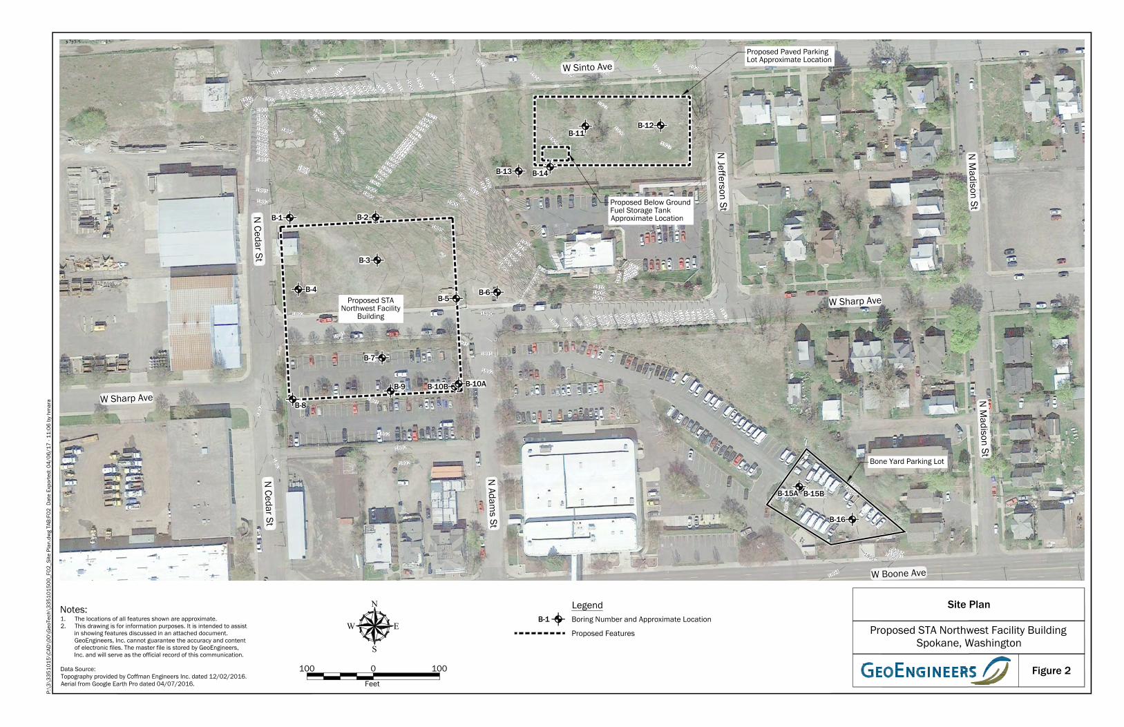
1895
1900
1905
1910
1915
1891189218931894
1896189718981899
1901
1902
1903 1904
1906190719081909
1911191219131914
19161917
19181919
1905
1910
1915
1920
1904
1906
19071908
1909
1911191219131914
1916
1917
19181919
1921
1910
1905
1895
1900
1905
19051900
18941893
18951900
1905
1910
19151920
191019051900
19201915191019051900
1895
1925
192619271927
19201921
1922
1923
19231926
1927
1928
1892
1891
1895
1900
1905
1910
19151891
18921893189418961897189818991901190219031904 19
0619
0719
0819
09
1911
1912
1913
1914
19161917
19001895
1890
1915
1917
191819191920
19211922
1923
1892
18941895
189918981897
1896
1895
1894
189318
93
1901190018991898189718961895
1892
1891
1892
1891
1892
1892
1895
1900
1905
1910
1915
1891189218931894
1896189718981899
1901
1902
1903 1904
1906190719081909
1911191219131914
19161917
19181919
1905
1910
1915
1920
1904
1906
19071908
1909
1911191219131914
1916
1917
19181919
1921
1915 1916
1917
1910
1905
1895
1900
1905
19051900
18941893
18951900
1905
1910
19151920
191019051900
19201915191019051900
1895
1925
192619271927
19201921
1922
1923
19231924
19251926
1927
1928
1892
1892
1891
1895
1900
1905
1910
19151891
18921893189418961897189818991901190219031904 19
0619
0719
0819
09
1911
1912
1913
1914
19161917
19001895
1927
1890
1915
1917
191819191920
19211922
1923
1893
1892
1891
1892
18941895
189918981897
1896
1895
1894
189318
93
1901190018991898189718961895
1892
1891
1892
1891
1892
1892
1891
B-1 B-2
B-3
B-4
B-8
B-6
B-9 B-10B
B-7
B-16
B-11B-12
B-5
B-10A
B-15BB-15A
W Sharp Ave
W Sharp Ave
N Adam
s St
N Cedar St
W Sinto Ave
N Jefferson St
N M
adison StN
Madison St
N Cedar St
W Boone Ave
Proposed STANorthwest Facility
Building
Bone Yard Parking Lot
Proposed Below GroundFuel Storage TankApproximate Location
Proposed Paved ParkingLot Approximate Location
B-14B-13
Figure 2
Proposed STA Northwest Facility BuildingSpokane, Washington
Site Plan
W E
N
S
LegendNotes:1. The locations of all features shown are approximate.2. This drawing is for information purposes. It is intended to assist
in showing features discussed in an attached document.GeoEngineers, Inc. cannot guarantee the accuracy and contentof electronic files. The master file is stored by GeoEngineers,Inc. and will serve as the official record of this communication.
Data Source:Topography provided by Coffman Engineers Inc. dated 12/02/2016.Aerial from Google Earth Pro dated 04/07/2016. Feet
0100 100
P:\3
\335
1015
\CAD
\00\
Geo
Tech
\335
1015
00_F
02_S
ite P
lan.
dwg
TAB:
F02
Dat
e Ex
porte
d: 0
4/06
/17
- 11:
06 b
y hm
ara
Boring Number and Approximate LocationB-1
Proposed Features

AP
PE
ND
ICE
S

APPENDIX A Field Explorations and Laboratory Testing
April 6, 2017 | Page A-1 File No. 3351-015-00
APPENDIX A FIELD EXPLORATIONS AND LABORATORY TESTING
Field Explorations
Soil conditions at the proposed STA Northwest Facility Building site were explored between December 7 and 12, 2016, by drilling 18 borings (B-1 through B-9, B-10A, B-10B, B-11 through B-14, B-15A, B-15B and B-16) at the approximate locations shown on Figure 2. The borings were advanced to depths in the range of about 2½ to 40 feet below the existing ground surface using a truck-mounted CME 75 hollow-stem auger drill rig owned and operated by GeoEngineers.
Samples of soil encountered in the borings were obtained at approximate 2½- to 5-foot-depth intervals using 2.4-inch, inside-diameter, California-style, split-barrel samplers. The samplers were driven into the soil using a 140-pound automatic hammer, free-falling 30 inches on each blow. The number of blows required to drive the samplers each of three, 6-inch increments of penetration were recorded in the field, along with visual-manual descriptions of soil based on ASTM D 2488. The sum of the blow counts for the last two, 6-inch increments of penetration, unless otherwise noted, is reported on the boring logs. Blow counts were converted to approximate Standard Penetration Test (SPT) N-values and are shown on the logs. The conversion of non-standard penetration resistance to SPT N-values was made using the Lacroix-Horn equation (ASTM SPT-523, 1973).
The borings were continuously monitored by an engineer from our firm who examined and classified the soil encountered, obtained representative soil samples and maintained a detailed log of the explorations. Soil encountered in the explorations was classified in the field in general accordance with ASTM D 2488, the Standard Practice for Classification of Soils, Visual-Manual Procedure, which is summarized in Figure A-1. Logs of the borings are presented in Logs of Borings, Figures A-2 through A-19. The logs are based on interpretation of the field and laboratory data, and indicate the depth at which subsurface materials or their characteristics change, although these changes might actually be gradual.
The boring locations were selected based on “Conceptual Site Plan – 1” provided by Coffman Engineers. The exploration locations were established in the field using an IPAD equipped with GPS and GISPro software or by taping and pacing from existing site features. Final exploration locations, with the exception of borings B-10A, B-14, B-15A, B-15B and B-16, were surveyed by Coffman Engineers. Exploration elevations reported on the boring logs were determined by interpolating between elevation contours on a topographic map of the site dated December 2, 2016 provided by Coffman Engineers. Exploration locations and elevations should be considered accurate to the degree implied by the method used.
Laboratory Testing
Soil samples obtained from the explorations were returned to our laboratory for further examination and testing. Representative soil samples were selected for laboratory tests to evaluate select geotechnical engineering characteristics of the site soil and to confirm or revise our field classification. Soil samples obtained from the borings were visually classified in the field and/or in our laboratory using the USCS and ASTM classification methods. ASTM test method D 2488 (Practice for Description and Identification of Soils) was used in the field to visually classify the soil samples, while ASTM D 2487 (Classification of Soils for Engineering Purposes) was used to classify the soil based on laboratory tests results. These classification procedures are incorporated in the Log of Borings shown in Figures A-2 through A-19.
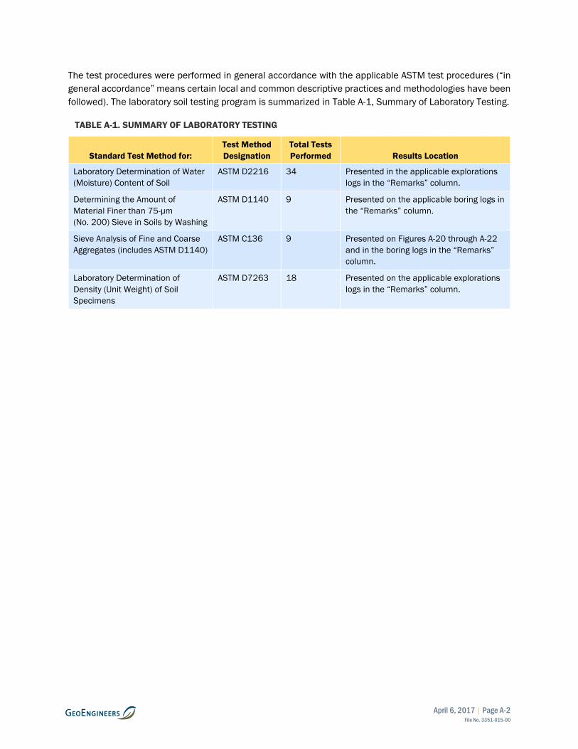
April 6, 2017 | Page A-2 File No. 3351-015-00
The test procedures were performed in general accordance with the applicable ASTM test procedures (“in general accordance” means certain local and common descriptive practices and methodologies have been followed). The laboratory soil testing program is summarized in Table A-1, Summary of Laboratory Testing.
TABLE A-1. SUMMARY OF LABORATORY TESTING
Standard Test Method for: Test Method Designation
Total Tests Performed Results Location
Laboratory Determination of Water (Moisture) Content of Soil
ASTM D2216 34 Presented in the applicable explorations logs in the “Remarks” column.
Determining the Amount of Material Finer than 75-μm (No. 200) Sieve in Soils by Washing
ASTM D1140 9 Presented on the applicable boring logs in the “Remarks” column.
Sieve Analysis of Fine and Coarse Aggregates (includes ASTM D1140)
ASTM C136 9 Presented on Figures A-20 through A-22 and in the boring logs in the “Remarks” column.
Laboratory Determination of Density (Unit Weight) of Soil Specimens
ASTM D7263 18 Presented on the applicable explorations logs in the “Remarks” column.

Measured groundwater level in exploration,well, or piezometer
Measured free product in well or piezometer
Distinct contact between soil strata
Approximate contact between soil strata
Contact between geologic units
SYMBOLS TYPICALDESCRIPTIONS
GW
GP
SW
SP
SM
FINEGRAINED
SOILS
SILTS ANDCLAYS
NOTE: Multiple symbols are used to indicate borderline or dual soil classifications
MORE THAN 50%RETAINED ONNO. 200 SIEVE
MORE THAN 50%PASSING
NO. 200 SIEVE
GRAVELAND
GRAVELLYSOILS
SC
LIQUID LIMITLESS THAN 50
(APPRECIABLE AMOUNTOF FINES)
(APPRECIABLE AMOUNTOF FINES)
COARSEGRAINED
SOILS
MAJOR DIVISIONSGRAPH LETTER
GM
GC
ML
CL
OL
SILTS ANDCLAYS
SANDS WITHFINES
SANDAND
SANDYSOILS
MH
CH
OH
PT
(LITTLE OR NO FINES)
CLEAN SANDS
GRAVELS WITHFINES
CLEAN GRAVELS
(LITTLE OR NO FINES)
WELL-GRADED GRAVELS, GRAVEL -SAND MIXTURES
CLAYEY GRAVELS, GRAVEL - SAND -CLAY MIXTURES
WELL-GRADED SANDS, GRAVELLYSANDS
POORLY-GRADED SANDS, GRAVELLYSAND
SILTY SANDS, SAND - SILT MIXTURES
CLAYEY SANDS, SAND - CLAYMIXTURES
INORGANIC SILTS, ROCK FLOUR,CLAYEY SILTS WITH SLIGHTPLASTICITY
INORGANIC CLAYS OF LOW TOMEDIUM PLASTICITY, GRAVELLYCLAYS, SANDY CLAYS, SILTY CLAYS,LEAN CLAYS
ORGANIC SILTS AND ORGANIC SILTYCLAYS OF LOW PLASTICITY
INORGANIC SILTS, MICACEOUS ORDIATOMACEOUS SILTY SOILS
INORGANIC CLAYS OF HIGHPLASTICITY
ORGANIC CLAYS AND SILTS OFMEDIUM TO HIGH PLASTICITY
PEAT, HUMUS, SWAMP SOILS WITHHIGH ORGANIC CONTENTSHIGHLY ORGANIC SOILS
SOIL CLASSIFICATION CHART
MORE THAN 50%OF COARSE
FRACTION RETAINEDON NO. 4 SIEVE
MORE THAN 50%OF COARSE
FRACTION PASSINGON NO. 4 SIEVE
SILTY GRAVELS, GRAVEL - SAND -SILT MIXTURES
POORLY-GRADED GRAVELS,GRAVEL - SAND MIXTURES
LIQUID LIMIT GREATERTHAN 50
Figure A-1
Continuous Coring
Bulk or grab
Direct-Push
Piston
Shelby tube
Standard Penetration Test (SPT)
2.4-inch I.D. split barrel
Contact between soil of the same geologicunit
Material Description Contact
Graphic Log Contact
NOTE: The reader must refer to the discussion in the report text and the logs of explorations for a proper understanding of subsurface conditions.Descriptions on the logs apply only at the specific exploration locations and at the time the explorations were made; they are not warranted to berepresentative of subsurface conditions at other locations or times.
Groundwater Contact
Key to Exploration Logs
Sampler Symbol Descriptions
ADDITIONAL MATERIAL SYMBOLS
NSSSMSHS
No Visible SheenSlight SheenModerate SheenHeavy Sheen
Sheen Classification
SYMBOLS
Asphalt Concrete
Cement Concrete
Crushed Rock/Quarry Spalls
Topsoil
GRAPH LETTER
AC
CC
SOD Sod/Forest Duff
CR
DESCRIPTIONSTYPICAL
TS
Laboratory / Field Tests%F%GALCACPCSDDDSHAMCMDMohsOCPMPIPPSATXUCVS
Percent finesPercent gravelAtterberg limitsChemical analysisLaboratory compaction testConsolidation testDry densityDirect shearHydrometer analysisMoisture contentMoisture contentMohs hardness scaleOrganic contentPermeability or hydraulic conductivityPlasticity indexPocket penetrometerSieve analysisTriaxial compressionUnconfined compressionVane shear
Blowcount is recorded for driven samplers as the number ofblows required to advance sampler 12 inches (or distance noted).See exploration log for hammer weight and drop.
"P" indicates sampler pushed using the weight of the drill rig.
"WOH" indicates sampler pushed using the weight of thehammer.
Rev 02/2017

B-1(1)CA1
B-1(1-2.5)CA
2B-1(3.5-5)
3MD
B-1(6-7.5)
4MC; %F
B-1(8.5-10)
5
6MC; SA
7
GM
GM
GW-GM
Dark brown silty fine to coarse gravel with sand(medium dense, moist)
Brown silty fine to coarse gravel with sand andoccasional cobbles (medium dense, moist)
Brownish gray fine to coarse gravel with silt, sand andoccasional cobbles (medium dense, moist)
6
6
7
8
6
16
10
62
141*
51
47
123*
124*
32
NS
NS
NS
NS
NS
NS
NS
<1
<1
<1
<1
<1
<1
<1
Approximate SPT N-value is 25
Approximate SPT N-value is 50+*Sampler on apparent cobble; blow count likely
overstated
MC=4%; Dry Density=116 pcfApproximate SPT N-value is 21
MC=3%; %F=5.8Approximate SPT N-value is 19
Approximate SPT N-value is 50+*Sampler on apparent cobble; blow count likely
overstated
MC=3%; SA (%F=7.7)Approximate SPT N-value is 50+
*Sampler on apparent cobble; blow count likelyoverstated
Approximate SPT N-value is 13
Notes:
12/7/2016 12/7/2016 25JJBEBD GeoEngineers, Inc. Hollow-Stem Auger
CME-75, Truck MountedDrillingEquipment
Autohammer140 (lbs) / 30 (in) Drop
WA State Plane NorthNAD83 (feet)
2478087262774
1893NAVD88
Easting (X)Northing (Y)
Surface Elevation (ft)Vertical Datum
DrilledStart End Total
Depth (ft)Logged ByChecked By
HammerData
SystemDatum
Driller DrillingMethod
Groundwater not observed at time of exploration
Note: See Figure A-1 for explanation of symbols.Coordinates Data Source: Horizontal approximated based on Topographic Survey, Vertical approximated based on Topographic Survey
Spo
kane
: D
ate:
3/1
0/1
7 P
ath:
W:\
PRO
JEC
TS\3
\33
51
01
5\G
INT\
33
51
01
50
0.G
PJ D
BTe
mpl
ate/
LibT
empl
ate:
GEO
ENG
INEE
RS
_DF_
STD
_US
_20
17
.GD
T/G
EI8
_EN
VIR
ON
MEN
TAL_
STA
ND
ARD
_NO
_GW
Elev
atio
n (f
eet)
1890
1885
1880
1875
1870
Dep
th (f
eet)
0
5
10
15
20
25
Inte
rval
Gra
phic
Log
FIELD DATA
Sam
ple
Nam
eTe
stin
g
Col
lect
ed S
ampl
e
Gro
upC
lass
ifica
tion MATERIAL
DESCRIPTION
Rec
over
ed (i
n)
Blo
ws/
foot
Sheet 1 of 1Project Number:
Project Location:
Project:
Spokane, Washington
3351-015-00
Log of Boring B-1Proposed STA Northwest Facility Building
Figure A-2
She
en
Hea
dspa
ceVa
por
(ppm
) REMARKS

B-2(1)1
B-2(1-2.5)CA
2B-2(3.5-5)
3B-2(6-7.5)
4MD
B-2(8.5-10)
5
6
TS
GM
GP-GM
Approximately 3 inches of dark brown silty fine tocoarse sand with gravel and organic matter (roots)(medium dense, moist) (topsoil)
Dark brown silty fine to coarse gravel with sand andoccasional debris (pieces of metal and wood)(medium dense, moist) (fill)
Brown fine to coarse gravel with silt, sand andoccasional cobbles (medium dense, moist)
Grades to dense
12
6
5
9
6
8
25
54
146*
54
146*
88
NS
NS
NS
NS
NS
NS
<1
<1
<1
<1
<1
<1
Approximate SPT N-value is 10
Approximate SPT N-value is 22
Approximate SPT N-value is 50+*Sampler on apparent cobble; blow count likely
overstated
MC=3%; Dry Density=112 pcfApproximate SPT N-value is 22
Approximate SPT N-value is 50+*Sampler on apparent cobble; blow count likely
overstated
Approximate SPT N-value is 36
Notes:
12/7/2016 12/7/2016 20JJBEBD GeoEngineers, Inc. Hollow-Stem Auger
CME-75, Truck MountedDrillingEquipment
Autohammer140 (lbs) / 30 (in) Drop
WA State Plane NorthNAD83 (feet)
2478217262775
1891.5NAVD88
Easting (X)Northing (Y)
Surface Elevation (ft)Vertical Datum
DrilledStart End Total
Depth (ft)Logged ByChecked By
HammerData
SystemDatum
Driller DrillingMethod
Groundwater not observed at time of exploration
Note: See Figure A-1 for explanation of symbols.Coordinates Data Source: Horizontal approximated based on Topographic Survey, Vertical approximated based on Topographic Survey
Spo
kane
: D
ate:
3/1
0/1
7 P
ath:
W:\
PRO
JEC
TS\3
\33
51
01
5\G
INT\
33
51
01
50
0.G
PJ D
BTe
mpl
ate/
LibT
empl
ate:
GEO
ENG
INEE
RS
_DF_
STD
_US
_20
17
.GD
T/G
EI8
_EN
VIR
ON
MEN
TAL_
STA
ND
ARD
_NO
_GW
Elev
atio
n (f
eet)
1890
1885
1880
1875
Dep
th (f
eet)
0
5
10
15
20
Inte
rval
Gra
phic
Log
FIELD DATA
Sam
ple
Nam
eTe
stin
g
Col
lect
ed S
ampl
e
Gro
upC
lass
ifica
tion MATERIAL
DESCRIPTION
Rec
over
ed (i
n)
Blo
ws/
foot
Sheet 1 of 1Project Number:
Project Location:
Project:
Spokane, Washington
3351-015-00
Log of Boring B-2Proposed STA Northwest Facility Building
Figure A-3
She
en
Hea
dspa
ceVa
por
(ppm
) REMARKS

B-3(1)1
B-3(1-2.5)
2B-3(3.5-5)
CA
3
4B-3(8.5-10)
5MD
6
GM
GP-GM
Dark brown silty fine to coarse gravel with sand(medium dense, moist)
Brown fine to coarse gravel with silt, sand andoccasional cobbles (medium dense, moist)
Grades to grayish brown
Grades to dense
16
14
0
14
15
5
35
49
61
24
89
112
NS
NS
NS
NS
NS
<1
<1
<1
<1
<1
Approximate SPT N-value is 14
Approximate SPT N-value is 20
Approximate SPT N-value is 25
Approximate SPT N-value is 10
MC=3%; Dry Density=129 pcfApproximate SPT N-value is 36
Approximate SPT N-value is 46
Notes:
12/7/2016 12/7/2016 20JJBEBD GeoEngineers, Inc. Hollow-Stem Auger
CME-75, Truck MountedDrillingEquipment
Autohammer140 (lbs) / 30 (in) Drop
WA State Plane NorthNAD83 (feet)
2478219262710
1893NAVD88
Easting (X)Northing (Y)
Surface Elevation (ft)Vertical Datum
DrilledStart End Total
Depth (ft)Logged ByChecked By
HammerData
SystemDatum
Driller DrillingMethod
Groundwater not observed at time of exploration
Note: See Figure A-1 for explanation of symbols.Coordinates Data Source: Horizontal approximated based on Topographic Survey, Vertical approximated based on Topographic Survey
Spo
kane
: D
ate:
3/1
0/1
7 P
ath:
W:\
PRO
JEC
TS\3
\33
51
01
5\G
INT\
33
51
01
50
0.G
PJ D
BTe
mpl
ate/
LibT
empl
ate:
GEO
ENG
INEE
RS
_DF_
STD
_US
_20
17
.GD
T/G
EI8
_EN
VIR
ON
MEN
TAL_
STA
ND
ARD
_NO
_GW
Elev
atio
n (f
eet)
1890
1885
1880
1875
Dep
th (f
eet)
0
5
10
15
20
Inte
rval
Gra
phic
Log
FIELD DATA
Sam
ple
Nam
eTe
stin
g
Col
lect
ed S
ampl
e
Gro
upC
lass
ifica
tion MATERIAL
DESCRIPTION
Rec
over
ed (i
n)
Blo
ws/
foot
Sheet 1 of 1Project Number:
Project Location:
Project:
Spokane, Washington
3351-015-00
Log of Boring B-3Proposed STA Northwest Facility Building
Figure A-4
She
en
Hea
dspa
ceVa
por
(ppm
) REMARKS

B-4(1)CA1
B-4(1-2.5)CA
2MD
B-4(3.5-5)
3B-4(6-7.5)
4B-4(8.5-10)
5
6MD
7
TS
GM
GP-GM
GP
GP-GM
Approximately 3 inches of dark brown silty fine tocoarse sand with gravel and organic matter (roots)(medium dense, moist) (topsoil)
Dark brown silty fine to coarse gravel with sand (loose,moist)
Brown fine to coarse gravel with silt, sand andoccasional cobbles (medium dense, moist)
Brown fine to coarse gravel with sand, trace silt andoccasional cobbles (dense, moist)
Grayish brown fine to coarse gravel with silt and sand(dense, moist)
16
14
16
8
11
16
15
42
46
138*
87
106
79
NS
NS
NS
NS
NS
NS
NS
<1
<1
<1
<1
<1
<1
<1
Approximate SPT N-value is 6
MC=7%; Dry Density=129 pcfApproximate SPT N-value is 17
Approximate SPT N-value is 19
Approximate SPT N-value is 50+*Sampler on apparent cobble; blow count likely
overstated
Approximate SPT N-value is 36
MC=3%; Dry Density=123 pcfApproximate SPT N-value is 44
Approximate SPT N-value is 32
Notes:
12/7/2016 12/7/2016 25JJBEBD GeoEngineers, Inc. Hollow-Stem Auger
CME-75, Truck MountedDrillingEquipment
Autohammer140 (lbs) / 30 (in) Drop
WA State Plane NorthNAD83 (feet)
2478100262666
1893NAVD88
Easting (X)Northing (Y)
Surface Elevation (ft)Vertical Datum
DrilledStart End Total
Depth (ft)Logged ByChecked By
HammerData
SystemDatum
Driller DrillingMethod
Groundwater not observed at time of exploration
Note: See Figure A-1 for explanation of symbols.Coordinates Data Source: Horizontal approximated based on Topographic Survey, Vertical approximated based on Topographic Survey
Spo
kane
: D
ate:
3/1
0/1
7 P
ath:
W:\
PRO
JEC
TS\3
\33
51
01
5\G
INT\
33
51
01
50
0.G
PJ D
BTe
mpl
ate/
LibT
empl
ate:
GEO
ENG
INEE
RS
_DF_
STD
_US
_20
17
.GD
T/G
EI8
_EN
VIR
ON
MEN
TAL_
STA
ND
ARD
_NO
_GW
Elev
atio
n (f
eet)
1890
1885
1880
1875
1870
Dep
th (f
eet)
0
5
10
15
20
25
Inte
rval
Gra
phic
Log
FIELD DATA
Sam
ple
Nam
eTe
stin
g
Col
lect
ed S
ampl
e
Gro
upC
lass
ifica
tion MATERIAL
DESCRIPTION
Rec
over
ed (i
n)
Blo
ws/
foot
Sheet 1 of 1Project Number:
Project Location:
Project:
Spokane, Washington
3351-015-00
Log of Boring B-4Proposed STA Northwest Facility Building
Figure A-5
She
en
Hea
dspa
ceVa
por
(ppm
) REMARKS

B-5(1)1
MDB-5(1-2.5)
2B-5(3.5-5)
CA
3B-5(6-7.5)
4MC; %F
B-5(8.5-10)
5
6
GP-GM
GP
Grayish brown fine to coarse gravel with silt and sand(medium dense, moist)
Brownish gray fine to coarse gravel with sand and tracesilt (medium dense to dense, moist)
12
10
8
8
8
10
40
57
58
74
61
97
NS
NS
NS
NS
NS
NS
<1
<1
<1
<1
3.1
1
MC=4%; Dry Density=125 pcfApproximate SPT N-value is 16
Approximate SPT N-value is 23
Approximate SPT N-value is 24
MC=3%; %F=3.0Approximate SPT N-value is 30
Approximate SPT N-value is 25
Approximate SPT N-value is 40
Notes:
12/8/2016 12/8/2016 20JJBEBD GeoEngineers, Inc. Hollow-Stem Auger
CME-75, Truck MountedDrillingEquipment
Autohammer140 (lbs) / 30 (in) Drop
WA State Plane NorthNAD83 (feet)
2478339262652
1890.5NAVD88
Easting (X)Northing (Y)
Surface Elevation (ft)Vertical Datum
DrilledStart End Total
Depth (ft)Logged ByChecked By
HammerData
SystemDatum
Driller DrillingMethod
Groundwater not observed at time of exploration
Note: See Figure A-1 for explanation of symbols.Coordinates Data Source: Horizontal approximated based on Topographic Survey, Vertical approximated based on Topographic Survey
Spo
kane
: D
ate:
3/1
0/1
7 P
ath:
W:\
PRO
JEC
TS\3
\33
51
01
5\G
INT\
33
51
01
50
0.G
PJ D
BTe
mpl
ate/
LibT
empl
ate:
GEO
ENG
INEE
RS
_DF_
STD
_US
_20
17
.GD
T/G
EI8
_EN
VIR
ON
MEN
TAL_
STA
ND
ARD
_NO
_GW
Elev
atio
n (f
eet)
1890
1885
1880
1875
Dep
th (f
eet)
0
5
10
15
20
Inte
rval
Gra
phic
Log
FIELD DATA
Sam
ple
Nam
eTe
stin
g
Col
lect
ed S
ampl
e
Gro
upC
lass
ifica
tion MATERIAL
DESCRIPTION
Rec
over
ed (i
n)
Blo
ws/
foot
Sheet 1 of 1Project Number:
Project Location:
Project:
Spokane, Washington
3351-015-00
Log of Boring B-5Proposed STA Northwest Facility Building
Figure A-6
She
en
Hea
dspa
ceVa
por
(ppm
) REMARKS

B-6(1)CA1
B-6(1-2.5)CA
2B-6(3.5-5)
3MC; %F
B-6(6-7.5)
4B-6(8.5-10)
5MC; %F; MD
6
7
GP-GM
GP
GP-GM
Brown fine to coarse gravel with silt, sand andoccasional cobbles (medium dense, moist)
Brown fine to coarse gravel with sand and trace silt(medium dense to dense, moist)
Brown fine to coarse gravel with silt and sand (mediumdense to dense, moist)
14
12
8
10
14
12
14
49
46
44
72
71
90
66
NS
NS
NS
NS
NS
NS
NS
<1
<1
1
<1
<1
<1
1.3
Approximate SPT N-value is 20
Approximate SPT N-value is 19
MC=2%; %F=3.1Approximate SPT N-value is 18
Approximate SPT N-value is 30
MC=3%; %F=3.6; Dry Density=127 pcfApproximate SPT N-value is 29
Approximate SPT N-value is 37
Approximate SPT N-value is 27
Notes:
12/8/2016 12/8/2016 25JJBEBD GeoEngineers, Inc. Hollow-Stem Auger
CME-75, Truck MountedDrillingEquipment
Autohammer140 (lbs) / 30 (in) Drop
WA State Plane NorthNAD83 (feet)
2478401262661
1890.5NAVD88
Easting (X)Northing (Y)
Surface Elevation (ft)Vertical Datum
DrilledStart End Total
Depth (ft)Logged ByChecked By
HammerData
SystemDatum
Driller DrillingMethod
Groundwater not observed at time of exploration
Note: See Figure A-1 for explanation of symbols.Coordinates Data Source: Horizontal approximated based on Topographic Survey, Vertical approximated based on Topographic Survey
Spo
kane
: D
ate:
3/1
0/1
7 P
ath:
W:\
PRO
JEC
TS\3
\33
51
01
5\G
INT\
33
51
01
50
0.G
PJ D
BTe
mpl
ate/
LibT
empl
ate:
GEO
ENG
INEE
RS
_DF_
STD
_US
_20
17
.GD
T/G
EI8
_EN
VIR
ON
MEN
TAL_
STA
ND
ARD
_NO
_GW
Elev
atio
n (f
eet)
1890
1885
1880
1875
1870
Dep
th (f
eet)
0
5
10
15
20
25
Inte
rval
Gra
phic
Log
FIELD DATA
Sam
ple
Nam
eTe
stin
g
Col
lect
ed S
ampl
e
Gro
upC
lass
ifica
tion MATERIAL
DESCRIPTION
Rec
over
ed (i
n)
Blo
ws/
foot
Sheet 1 of 1Project Number:
Project Location:
Project:
Spokane, Washington
3351-015-00
Log of Boring B-6Proposed STA Northwest Facility Building
Figure A-7
She
en
Hea
dspa
ceVa
por
(ppm
) REMARKS
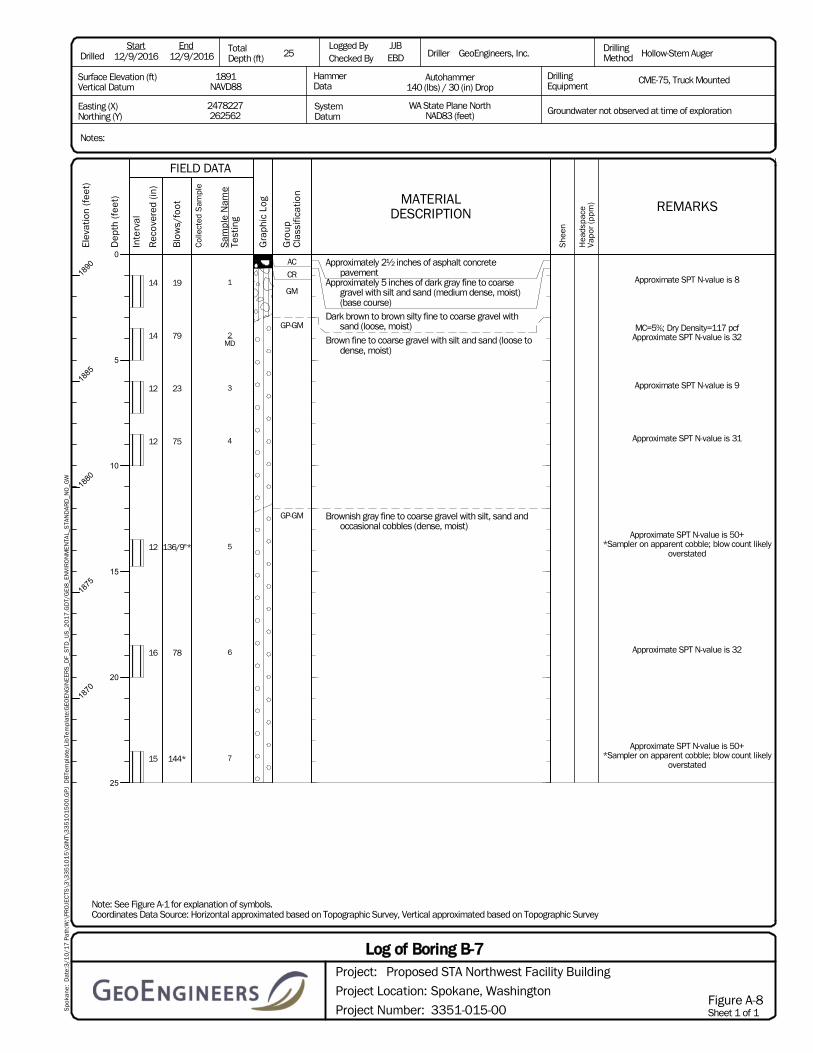
1
2MD
3
4
5
6
7
AC
CR
GM
GP-GM
GP-GM
Approximately 2½ inches of asphalt concretepavement
Approximately 5 inches of dark gray fine to coarsegravel with silt and sand (medium dense, moist)(base course)
Dark brown to brown silty fine to coarse gravel withsand (loose, moist)
Brown fine to coarse gravel with silt and sand (loose todense, moist)
Brownish gray fine to coarse gravel with silt, sand andoccasional cobbles (dense, moist)
14
14
12
12
12
16
15
19
79
23
75
136/9"*
78
144*
Approximate SPT N-value is 8
MC=5%; Dry Density=117 pcfApproximate SPT N-value is 32
Approximate SPT N-value is 9
Approximate SPT N-value is 31
Approximate SPT N-value is 50+*Sampler on apparent cobble; blow count likely
overstated
Approximate SPT N-value is 32
Approximate SPT N-value is 50+*Sampler on apparent cobble; blow count likely
overstated
Notes:
12/9/2016 12/9/2016 25JJBEBD GeoEngineers, Inc. Hollow-Stem Auger
CME-75, Truck MountedDrillingEquipment
Autohammer140 (lbs) / 30 (in) Drop
WA State Plane NorthNAD83 (feet)
2478227262562
1891NAVD88
Easting (X)Northing (Y)
Surface Elevation (ft)Vertical Datum
DrilledStart End Total
Depth (ft)Logged ByChecked By
HammerData
SystemDatum
Driller DrillingMethod
Groundwater not observed at time of exploration
Note: See Figure A-1 for explanation of symbols.Coordinates Data Source: Horizontal approximated based on Topographic Survey, Vertical approximated based on Topographic Survey
Spo
kane
: D
ate:
3/1
0/1
7 P
ath:
W:\
PRO
JEC
TS\3
\33
51
01
5\G
INT\
33
51
01
50
0.G
PJ D
BTe
mpl
ate/
LibT
empl
ate:
GEO
ENG
INEE
RS
_DF_
STD
_US
_20
17
.GD
T/G
EI8
_EN
VIR
ON
MEN
TAL_
STA
ND
ARD
_NO
_GW
Elev
atio
n (f
eet)
1890
1885
1880
1875
1870
Dep
th (f
eet)
0
5
10
15
20
25
Inte
rval
Gra
phic
Log
FIELD DATA
Sam
ple
Nam
eTe
stin
g
Col
lect
ed S
ampl
e
Gro
upC
lass
ifica
tion MATERIAL
DESCRIPTION
Rec
over
ed (i
n)
Blo
ws/
foot
Sheet 1 of 1Project Number:
Project Location:
Project:
Spokane, Washington
3351-015-00
Log of Boring B-7Proposed STA Northwest Facility Building
Figure A-8
She
en
Hea
dspa
ceVa
por
(ppm
) REMARKS

1
2
3MC; %F
4MD
5MC; SA
6
AC
CR
GM
GP-GM
GP
GP-GM
Approximately 3 inches of asphalt concrete pavementApproximately 5 inches of dark gray fine to coarse
gravel with silt and sand (medium dense, moist)(base course)
Dark brown silty fine to coarse gravel with sand (loose,moist)
Brown fine to coarse gravel with silt and sand (loose,moist)
Grayish brown fine to coarse gravel with sand and tracesilt (medium dense, moist)
Gray-brown fine to coarse gravel with silt, sand andoccasional cobbles (medium dense, moist)
Grades to dense
Boring terminated at approximately 19 feet due toauger refusal
16
14
12
16
16
0
20
23
38
68
146*
120/5.5"*
Approximate SPT N-value is 8
Approximate SPT N-value is 9
MC=3%; %F=4.6Approximate SPT N-value is 16
MC=3%; Dry Density=123 pcfApproximate SPT N-value is 28
MC=4%; SA (%F=10.2)Approximate SPT N-value is 50+
*Sampler on apparent cobble; blow count likelyoverstated
Approximate SPT N-value is 50+*Sampler on apparent cobble; blow count likely
overstated
Notes:
12/8/2016 12/8/2016 19JJBEBD GeoEngineers, Inc. Hollow-Stem Auger
CME-75, Truck MountedDrillingEquipment
Autohammer140 (lbs) / 30 (in) Drop
WA State Plane NorthNAD83 (feet)
2478091262499
1892NAVD88
Easting (X)Northing (Y)
Surface Elevation (ft)Vertical Datum
DrilledStart End Total
Depth (ft)Logged ByChecked By
HammerData
SystemDatum
Driller DrillingMethod
Groundwater not observed at time of exploration
Note: See Figure A-1 for explanation of symbols.Coordinates Data Source: Horizontal approximated based on Topographic Survey, Vertical approximated based on Topographic Survey
Spo
kane
: D
ate:
3/1
0/1
7 P
ath:
W:\
PRO
JEC
TS\3
\33
51
01
5\G
INT\
33
51
01
50
0.G
PJ D
BTe
mpl
ate/
LibT
empl
ate:
GEO
ENG
INEE
RS
_DF_
STD
_US
_20
17
.GD
T/G
EI8
_EN
VIR
ON
MEN
TAL_
STA
ND
ARD
_NO
_GW
Elev
atio
n (f
eet)
1890
1885
1880
1875
Dep
th (f
eet)
0
5
10
15
Inte
rval
Gra
phic
Log
FIELD DATA
Sam
ple
Nam
eTe
stin
g
Col
lect
ed S
ampl
e
Gro
upC
lass
ifica
tion MATERIAL
DESCRIPTION
Rec
over
ed (i
n)
Blo
ws/
foot
Sheet 1 of 1Project Number:
Project Location:
Project:
Spokane, Washington
3351-015-00
Log of Boring B-8Proposed STA Northwest Facility Building
Figure A-9
She
en
Hea
dspa
ceVa
por
(ppm
) REMARKS
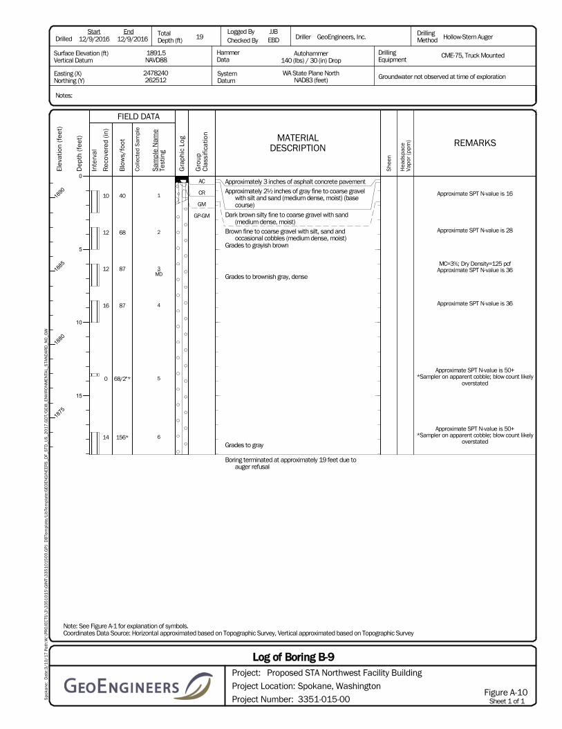
1
2
3MD
4
5
6
AC
CR
GM
GP-GM
Approximately 3 inches of asphalt concrete pavementApproximately 2½ inches of gray fine to coarse gravel
with silt and sand (medium dense, moist) (basecourse)
Dark brown silty fine to coarse gravel with sand(medium dense, moist)
Brown fine to coarse gravel with silt, sand andoccasional cobbles (medium dense, moist)
Grades to grayish brown
Grades to brownish gray, dense
Grades to gray
Boring terminated at approximately 19 feet due toauger refusal
10
12
12
16
0
14
40
68
87
87
68/2"*
156*
Approximate SPT N-value is 16
Approximate SPT N-value is 28
MC=3%; Dry Density=125 pcfApproximate SPT N-value is 36
Approximate SPT N-value is 36
Approximate SPT N-value is 50+*Sampler on apparent cobble; blow count likely
overstated
Approximate SPT N-value is 50+*Sampler on apparent cobble; blow count likely
overstated
Notes:
12/9/2016 12/9/2016 19JJBEBD GeoEngineers, Inc. Hollow-Stem Auger
CME-75, Truck MountedDrillingEquipment
Autohammer140 (lbs) / 30 (in) Drop
WA State Plane NorthNAD83 (feet)
2478240262512
1891.5NAVD88
Easting (X)Northing (Y)
Surface Elevation (ft)Vertical Datum
DrilledStart End Total
Depth (ft)Logged ByChecked By
HammerData
SystemDatum
Driller DrillingMethod
Groundwater not observed at time of exploration
Note: See Figure A-1 for explanation of symbols.Coordinates Data Source: Horizontal approximated based on Topographic Survey, Vertical approximated based on Topographic Survey
Spo
kane
: D
ate:
3/1
0/1
7 P
ath:
W:\
PRO
JEC
TS\3
\33
51
01
5\G
INT\
33
51
01
50
0.G
PJ D
BTe
mpl
ate/
LibT
empl
ate:
GEO
ENG
INEE
RS
_DF_
STD
_US
_20
17
.GD
T/G
EI8
_EN
VIR
ON
MEN
TAL_
STA
ND
ARD
_NO
_GW
Elev
atio
n (f
eet)
1890
1885
1880
1875
Dep
th (f
eet)
0
5
10
15
Inte
rval
Gra
phic
Log
FIELD DATA
Sam
ple
Nam
eTe
stin
g
Col
lect
ed S
ampl
e
Gro
upC
lass
ifica
tion MATERIAL
DESCRIPTION
Rec
over
ed (i
n)
Blo
ws/
foot
Sheet 1 of 1Project Number:
Project Location:
Project:
Spokane, Washington
3351-015-00
Log of Boring B-9Proposed STA Northwest Facility Building
Figure A-10
She
en
Hea
dspa
ceVa
por
(ppm
) REMARKS

1
2
AC
CR
GM
GP-GM
Approximately 2½ inches of asphalt concretepavement
Approximately 9 inches of dark gray fine to coarsegravel with silt and sand (medium dense, moist)(base course)
Dark brown silty fine to coarse gravel with sand(medium dense, moist)
Brown fine to coarse gravel with silt, sand and cobbles(medium dense, moist)
Boring terminated at approximately 5 foot depth due toauger refusal
9
14
40
45
Approximate SPT N-value is 16
Approximate SPT N-value is 18
Notes:
12/9/2016 12/9/2016 5JJBEBD GeoEngineers, Inc. Hollow-Stem Auger
CME-75, Truck MountedDrillingEquipment
Autohammer140 (lbs) / 30 (in) Drop
WA State Plane NorthNAD83 (feet)
2478342262523
1891.5NAVD88
Easting (X)Northing (Y)
Surface Elevation (ft)Vertical Datum
DrilledStart End Total
Depth (ft)Logged ByChecked By
HammerData
SystemDatum
Driller DrillingMethod
Groundwater not observed at time of exploration
Note: See Figure A-1 for explanation of symbols.Coordinates Data Source: Horizontal approximated based on Topographic Survey, Vertical approximated based on Topographic Survey
Spo
kane
: D
ate:
3/1
0/1
7 P
ath:
W:\
PRO
JEC
TS\3
\33
51
01
5\G
INT\
33
51
01
50
0.G
PJ D
BTe
mpl
ate/
LibT
empl
ate:
GEO
ENG
INEE
RS
_DF_
STD
_US
_20
17
.GD
T/G
EI8
_EN
VIR
ON
MEN
TAL_
STA
ND
ARD
_NO
_GW
Elev
atio
n (f
eet)
1890
Dep
th (f
eet)
0
5
Inte
rval
Gra
phic
Log
FIELD DATA
Sam
ple
Nam
eTe
stin
g
Col
lect
ed S
ampl
e
Gro
upC
lass
ifica
tion MATERIAL
DESCRIPTION
Rec
over
ed (i
n)
Blo
ws/
foot
Sheet 1 of 1Project Number:
Project Location:
Project:
Spokane, Washington
3351-015-00
Log of Boring B-10AProposed STA Northwest Facility Building
Figure A-11
She
en
Hea
dspa
ceVa
por
(ppm
) REMARKS

1
2MC; %F
3MD
4MC; SA
5
AC
CR
GP-GM
SW-SM
Approximately 2½ inches of asphalt concretepavement
Approximately 7 inches of dark gray fine to coarsegravel with silt and sand (medium dense, moist)(base course)
Brown fine to coarse gravel with silt, sand andoccasional cobbles (dense, moist)
Grades to brownish gray
Brownish gray fine to coarse sand with silt and gravel(medium dense to dense, moist)
15
8
10
17
17
73
120/5"*
100/11"*
107
60
No samples taken between 0 and 5 feet bgs. SeeB-10A for soil conditions at these depths.
Approximate SPT N-value is 30
MC=4%; %F=7.0Approximate SPT N-value is 50+
*Sampler on apparent cobble; blow count likelyoverstated
MC=3%; Dry Density=125 pcfApproximate SPT N-value is 50+
*Sampler on apparent cobble; blow count likelyoverstated
MC=4%; SA (%F=6.3)Approximate SPT N-value is 44
Approximate SPT N-value is 25
Notes:
12/9/2016 12/9/2016 25JJBEBD GeoEngineers, Inc. Hollow-Stem Auger
CME-75, Truck MountedDrillingEquipment
Autohammer140 (lbs) / 30 (in) Drop
WA State Plane NorthNAD83 (feet)
2478337262519
1891.5NAVD88
Easting (X)Northing (Y)
Surface Elevation (ft)Vertical Datum
DrilledStart End Total
Depth (ft)Logged ByChecked By
HammerData
SystemDatum
Driller DrillingMethod
Groundwater not observed at time of exploration
Note: See Figure A-1 for explanation of symbols.Coordinates Data Source: Horizontal approximated based on Topographic Survey, Vertical approximated based on Topographic Survey
Spo
kane
: D
ate:
3/1
0/1
7 P
ath:
W:\
PRO
JEC
TS\3
\33
51
01
5\G
INT\
33
51
01
50
0.G
PJ D
BTe
mpl
ate/
LibT
empl
ate:
GEO
ENG
INEE
RS
_DF_
STD
_US
_20
17
.GD
T/G
EI8
_EN
VIR
ON
MEN
TAL_
STA
ND
ARD
_NO
_GW
Elev
atio
n (f
eet)
1890
1885
1880
1875
1870
Dep
th (f
eet)
0
5
10
15
20
25
Inte
rval
Gra
phic
Log
FIELD DATA
Sam
ple
Nam
eTe
stin
g
Col
lect
ed S
ampl
e
Gro
upC
lass
ifica
tion MATERIAL
DESCRIPTION
Rec
over
ed (i
n)
Blo
ws/
foot
Sheet 1 of 1Project Number:
Project Location:
Project:
Spokane, Washington
3351-015-00
Log of Boring B-10BProposed STA Northwest Facility Building
Figure A-12
She
en
Hea
dspa
ceVa
por
(ppm
) REMARKS

B-11(1)CA1
B-11(1-2.5)CA
2B-11(3.5-5)
3MD
B-11(6-7.5)
4B-11(8.5-10)
TS
SP-SM
GP
Approximately 3 inches of brown silty fine to mediumsand with gravel and organic matter (roots)(medium dense, moist) (topsoil)
Gray fine to coarse sand with silt and occasional debris(brick) (very loose to medium dense, moist) (fill)
Gray fine to coarse gravel with sand and trace silt(medium dense, moist)
12
12
10
14
15
6
30
63
<1
<1
<1
<1
Approximate SPT N-value is 6
Approximate SPT N-value is 2
MC=12%; Dry Density=96 pcfApproximate SPT N-value is 12
Approximate SPT N-value is 26
Notes:
12/12/2016 12/12/2016 10JJBEBD GeoEngineers, Inc. Hollow-Stem Auger
CME-75, Truck MountedDrillingEquipment
Autohammer140 (lbs) / 30 (in) Drop
WA State Plane NorthNAD83 (feet)
2478534262912
1926NAVD88
Easting (X)Northing (Y)
Surface Elevation (ft)Vertical Datum
DrilledStart End Total
Depth (ft)Logged ByChecked By
HammerData
SystemDatum
Driller DrillingMethod
Groundwater not observed at time of exploration
Note: See Figure A-1 for explanation of symbols.Coordinates Data Source: Horizontal approximated based on Topographic Survey, Vertical approximated based on Topographic Survey
Spo
kane
: D
ate:
3/1
0/1
7 P
ath:
W:\
PRO
JEC
TS\3
\33
51
01
5\G
INT\
33
51
01
50
0.G
PJ D
BTe
mpl
ate/
LibT
empl
ate:
GEO
ENG
INEE
RS
_DF_
STD
_US
_20
17
.GD
T/G
EI8
_EN
VIR
ON
MEN
TAL_
STA
ND
ARD
_NO
_GW
Elev
atio
n (f
eet)
1925
1920
Dep
th (f
eet)
0
5
10
Inte
rval
Gra
phic
Log
FIELD DATA
Sam
ple
Nam
eTe
stin
g
Col
lect
ed S
ampl
e
Gro
upC
lass
ifica
tion MATERIAL
DESCRIPTION
Rec
over
ed (i
n)
Blo
ws/
foot
Sheet 1 of 1Project Number:
Project Location:
Project:
Spokane, Washington
3351-015-00
Log of Boring B-11Proposed STA Northwest Facility Building
Figure A-13
She
en
Hea
dspa
ceVa
por
(ppm
) REMARKS

B-12(1)1
MDB-12(1-2.5)
CA
2B-12(3.5-5)
CA
3B-12(6-7.5)
4B-12(8.5-10)
TS
GM
GM
GP-GM
Approximately 2 inches of brown silty fine to mediumsand with gravel and organic matter (roots)(medium dense, moist) (topsoil)
Brown silty fine to coarse gravel with sand andoccasional debris (glass, shingle) (loose, moist) (fill)
Brown silty fine to coarse gravel with sand (mediumdense, moist)
Grayish brown fine to coarse gravel with silt and sand(medium dense, moist)
12
12
12
12
12
39
42
44
NS
<1
<1
1.4
1.7
MC=10%; Dry Density=102 pcfApproximately SPT N-value is 5
Approximately SPT N-value is 16
Approximately SPT N-value is 17
Approximately SPT N-value is 18
Notes:
12/12/2016 12/12/2016 10JJBEBD GeoEngineers, Inc. Hollow-Stem Auger
CME-75, Truck MountedDrillingEquipment
Autohammer140 (lbs) / 30 (in) Drop
WA State Plane NorthNAD83 (feet)
2478648262914
1927NAVD88
Easting (X)Northing (Y)
Surface Elevation (ft)Vertical Datum
DrilledStart End Total
Depth (ft)Logged ByChecked By
HammerData
SystemDatum
Driller DrillingMethod
Groundwater not observed at time of exploration
Note: See Figure A-1 for explanation of symbols.Coordinates Data Source: Horizontal approximated based on Topographic Survey, Vertical approximated based on Topographic Survey
Spo
kane
: D
ate:
3/1
0/1
7 P
ath:
W:\
PRO
JEC
TS\3
\33
51
01
5\G
INT\
33
51
01
50
0.G
PJ D
BTe
mpl
ate/
LibT
empl
ate:
GEO
ENG
INEE
RS
_DF_
STD
_US
_20
17
.GD
T/G
EI8
_EN
VIR
ON
MEN
TAL_
STA
ND
ARD
_NO
_GW
Elev
atio
n (f
eet)
1925
1920
Dep
th (f
eet)
0
5
10
Inte
rval
Gra
phic
Log
FIELD DATA
Sam
ple
Nam
eTe
stin
g
Col
lect
ed S
ampl
e
Gro
upC
lass
ifica
tion MATERIAL
DESCRIPTION
Rec
over
ed (i
n)
Blo
ws/
foot
Sheet 1 of 1Project Number:
Project Location:
Project:
Spokane, Washington
3351-015-00
Log of Boring B-12Proposed STA Northwest Facility Building
Figure A-14
She
en
Hea
dspa
ceVa
por
(ppm
) REMARKS

B-13(1)1
B-13(1-2.5)CA
2MD
B-13(3.5-5)CA
3B-13(6-7.5)
4MC; SA
B-13(8.5-10)
5MC; %F
6MD
7MC; SA
8
TS
GM
GP-GM
GP
SP
GP
SP-SM
Approximately 2 inches of brown fine to medium sandwith gravel and organic matter (roots) (mediumdense, moist) (topsoil)
Dark brown silty fine to coarse gravel with sand(medium dense, moist) (fill)
Brown fine to coarse gravel with silt and sand (mediumdense, moist)
Brown fine to coarse gravel with sand and trace silt(medium dense, moist)
Brownish gray fine to coarse sand with gravel and tracesilt (medium dense, moist)
Gray fine to coarse gravel with sand and trace silt(dense, moist)
Gray fine to coarse sand with silt and gravel (dense,moist)
10
16
14
12
10
12
10
28
25
27
29
32
103
117
83
NSNS
NS
NS
NS
NS
NS
NS
NS
1.2
<1
<1
1.4
3.1
<1
<1
<1
Approximate SPT N-value is 11
MC=7%; Dry Density=115 pcfApproximate SPT N-value is 10
Approximate SPT N-value is 11
MC=3%; SA (%F=3.3)Approximate SPT N-value is 12
MC=3%; %F=3.4Approximate SPT N-value is 13
MC=3%; Dry Density=122 pcfApproximate SPT N-value is 43
MC=3%; SA (%F=4.8)Approximate SPT N-value is 49
Approximate SPT N-value is 34
Notes:
12/8/2016 12/12/2016 40JJBEBD GeoEngineers, Inc. Hollow-Stem Auger
CME-75, Truck MountedDrillingEquipment
Autohammer140 (lbs) / 30 (in) Drop
WA State Plane NorthNAD83 (feet)
2478433262844
1924.5NAVD88
Easting (X)Northing (Y)
Surface Elevation (ft)Vertical Datum
DrilledStart End Total
Depth (ft)Logged ByChecked By
HammerData
SystemDatum
Driller DrillingMethod
Groundwater not observed at time of exploration
Note: See Figure A-1 for explanation of symbols.Coordinates Data Source: Horizontal approximated based on Topographic Survey, Vertical approximated based on Topographic Survey
Spo
kane
: D
ate:
3/1
0/1
7 P
ath:
W:\
PRO
JEC
TS\3
\33
51
01
5\G
INT\
33
51
01
50
0.G
PJ D
BTe
mpl
ate/
LibT
empl
ate:
GEO
ENG
INEE
RS
_DF_
STD
_US
_20
17
.GD
T/G
EI8
_EN
VIR
ON
MEN
TAL_
STA
ND
ARD
_NO
_GW
Elev
atio
n (f
eet)
1920
1915
1910
1905
1900
1895
Dep
th (f
eet)
0
5
10
15
20
25
30
Inte
rval
Gra
phic
Log
FIELD DATA
Sam
ple
Nam
eTe
stin
g
Col
lect
ed S
ampl
e
Gro
upC
lass
ifica
tion MATERIAL
DESCRIPTION
Rec
over
ed (i
n)
Blo
ws/
foot
Sheet 1 of 2Project Number:
Project Location:
Project:
Spokane, Washington
3351-015-00
Log of Boring B-13Proposed STA Northwest Facility Building
Figure A-15
She
en
Hea
dspa
ceVa
por
(ppm
) REMARKS
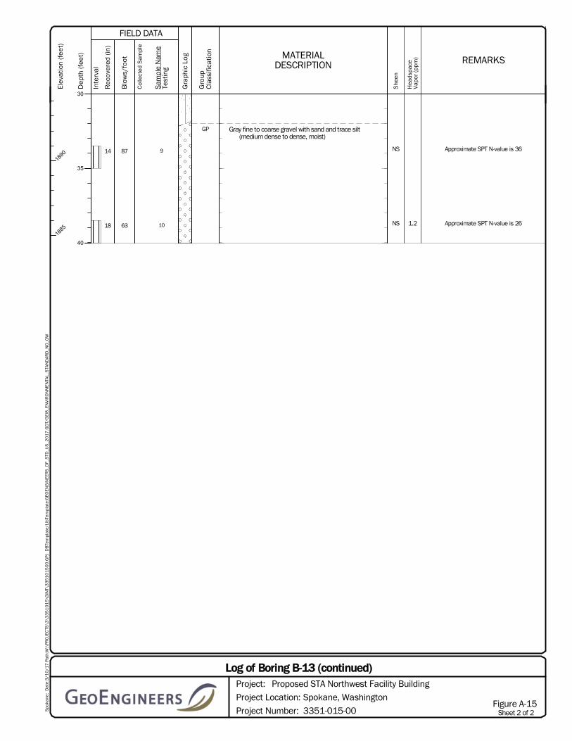
9
10
GP Gray fine to coarse gravel with sand and trace silt(medium dense to dense, moist)
14
18
87
63
NS
NS 1.2
Approximate SPT N-value is 36
Approximate SPT N-value is 26
Spo
kane
: D
ate:
3/1
0/1
7 P
ath:
W:\
PRO
JEC
TS\3
\33
51
01
5\G
INT\
33
51
01
50
0.G
PJ D
BTe
mpl
ate/
LibT
empl
ate:
GEO
ENG
INEE
RS
_DF_
STD
_US
_20
17
.GD
T/G
EI8
_EN
VIR
ON
MEN
TAL_
STA
ND
ARD
_NO
_GW
Elev
atio
n (f
eet)
1890
1885
Dep
th (f
eet)
30
35
40
Inte
rval
Gra
phic
Log
FIELD DATA
Sam
ple
Nam
eTe
stin
g
Col
lect
ed S
ampl
e
Gro
upC
lass
ifica
tion
MATERIALDESCRIPTION
Rec
over
ed (i
n)
Blo
ws/
foot
Sheet 2 of 2Project Number:
Project Location:
Project:
Spokane, Washington
3351-015-00
Log of Boring B-13 (continued)Proposed STA Northwest Facility Building
Figure A-15
She
en
Hea
dspa
ceVa
por
(ppm
) REMARKS

B-14(1)CA1
MDB-14(1-2.5)
CA
2B-14(3.5-5)
3MC; %F
B-14(6-7.5)
4B-14(8.5-10)
5MC; SA
6
TS
GM
GP-GM
GP
SP
Approximately 2 inches of brown silty fine to mediumsand with gravel and organic matter (roots)(medium dense, moist) (topsoil)
Dark brown silty fine to coarse gravel with sand(medium dense, moist) (fill)
Grayish brown fine to coarse gravel with silt and sand(medium dense, moist)
Brownish gray fine to coarse gravel with sand and tracesilt (medium dense, moist)
Gray fine to coarse sand with gravel and trace silt(medium dense, moist)
12
10
12
5
12
15
36
28
38
36
51
42
NS
NS
NS
NS
NS
NS
<1
<1
<1
<1
1.1
1.2
MC=8%; Dry Density=108 pcfApproximate SPT N-value is 15
Approximate SPT N-value is 11
MC=3%; %F=3.8Approximate SPT N-value is 16
Approximate SPT N-value is 15
MC=2%; SA (%F=3.0)Approximate SPT N-value is 21
Approximate SPT N-value is 17
Notes:
12/8/2016 12/8/2016 20JJBEBD GeoEngineers, Inc. Hollow-Stem Auger
CME-75, Truck MountedDrillingEquipment
Autohammer140 (lbs) / 30 (in) Drop
WA State Plane NorthNAD83 (feet)
2478481262851
1924.5NAVD88
Easting (X)Northing (Y)
Surface Elevation (ft)Vertical Datum
DrilledStart End Total
Depth (ft)Logged ByChecked By
HammerData
SystemDatum
Driller DrillingMethod
Groundwater not observed at time of exploration
Note: See Figure A-1 for explanation of symbols.Coordinates Data Source: Horizontal approximated based on Topographic Survey, Vertical approximated based on Topographic Survey
Spo
kane
: D
ate:
3/1
0/1
7 P
ath:
W:\
PRO
JEC
TS\3
\33
51
01
5\G
INT\
33
51
01
50
0.G
PJ D
BTe
mpl
ate/
LibT
empl
ate:
GEO
ENG
INEE
RS
_DF_
STD
_US
_20
17
.GD
T/G
EI8
_EN
VIR
ON
MEN
TAL_
STA
ND
ARD
_NO
_GW
Elev
atio
n (f
eet)
1920
1915
1910
1905
Dep
th (f
eet)
0
5
10
15
20
Inte
rval
Gra
phic
Log
FIELD DATA
Sam
ple
Nam
eTe
stin
g
Col
lect
ed S
ampl
e
Gro
upC
lass
ifica
tion MATERIAL
DESCRIPTION
Rec
over
ed (i
n)
Blo
ws/
foot
Sheet 1 of 1Project Number:
Project Location:
Project:
Spokane, Washington
3351-015-00
Log of Boring B-14Proposed STA Northwest Facility Building
Figure A-16
She
en
Hea
dspa
ceVa
por
(ppm
) REMARKS

B-15(1)1
B-15(1-2.5)CA
2B-15(3.5-5)
3B-15(6-7.5)
MD
4B-15(8.5-10)
MD; SA
5MC; SA
CR
SM
GP-GM
GW-GM
GW
Approximately 2 inches of gray fine to coarse gravelwith silt and sand (dense, moist) (gravel surfacing)
Dark brown silty fine to coarse sand with gravel andoccasional debris (brick fragments) (mediumdense, moist) (fill)
Brown fine to coarse gravel with silt and sand (mediumdense, moist)
Brown fine to coarse gravel with silt and sand (mediumdense, moist)
Gray fine to coarse gravel with sand and trace silt(dense, moist)
2
9
8
12
8
57
24
38
35
106
NS
NS
NS
NS
<1
<1
1
<1
1
Approximate SPT N-value is 23
Approximate SPT N-value is 10
MC=8%; Dry Density=101 pcfApproximate SPT N-value is 16
MC=4%; SA (%F=8.3) Dry Density=117 pcfApproximate SPT N-value is 14
MC=2%; SA (%F=4.4)Approximate SPT N-value is 44
Notes:
12/9/2016 12/9/2016 15JJBEBD GeoEngineers, Inc. Hollow-Stem Auger
CME-75, Truck MountedDrillingEquipment
Autohammer140 (lbs) / 30 (in) Drop
WA State Plane NorthNAD83 (feet)
2478857262367
1893.5NAVD88
Easting (X)Northing (Y)
Surface Elevation (ft)Vertical Datum
DrilledStart End Total
Depth (ft)Logged ByChecked By
HammerData
SystemDatum
Driller DrillingMethod
Groundwater not observed at time of exploration
Note: See Figure A-1 for explanation of symbols.Coordinates Data Source: Horizontal approximated based on Topographic Survey, Vertical approximated based on Topographic Survey
Spo
kane
: D
ate:
4/6
/17
Pat
h:P
:\3
\33
51
01
5\G
INT\
33
51
01
50
0.G
PJ
DB
Tem
plat
e/Li
bTem
plat
e:G
EOEN
GIN
EER
S_D
F_S
TD_U
S_2
01
7.G
DT/
GEI
8_E
NVI
RO
NM
ENTA
L_S
TAN
DAR
D_N
O_G
W
Elev
atio
n (f
eet)
1890
1885
1880
Dep
th (f
eet)
0
5
10
15
Inte
rval
Gra
phic
Log
FIELD DATA
Sam
ple
Nam
eTe
stin
g
Col
lect
ed S
ampl
e
Gro
upC
lass
ifica
tion MATERIAL
DESCRIPTION
Rec
over
ed (i
n)
Blo
ws/
foot
Sheet 1 of 1Project Number:
Project Location:
Project:
Spokane, Washington
3351-015-00
Log of Boring B-15AProposed STA Northwest Facility Building
Figure A-17
She
en
Hea
dspa
ceVa
por
(ppm
) REMARKS

B-15B(1)CA1
CR
SM
CR
Approximately 2 inches of gray fine to coarse gravelwith silt and sand (dense, moist) (gravel surfacing)
Blackish brown silty fine to coarse sand with gravel(medium dense, moist) (fill)
Basalt quarry spalls (fill)
2 62 Approximate SPT N-value is 25This boring was added to obtain additional
material to meet minimum environmental samplesize.
Notes:
12/9/2016 12/9/2016 2.5JJBEBD GeoEngineers, Inc. Hollow-Stem Auger
CME-75, Truck MountedDrillingEquipment
Autohammer140 (lbs) / 30 (in) Drop
WA State Plane NorthNAD83 (feet)
2478860262365
1893.5NAVD88
Easting (X)Northing (Y)
Surface Elevation (ft)Vertical Datum
DrilledStart End Total
Depth (ft)Logged ByChecked By
HammerData
SystemDatum
Driller DrillingMethod
Groundwater not observed at time of exploration
Note: See Figure A-1 for explanation of symbols.Coordinates Data Source: Horizontal approximated based on Topographic Survey, Vertical approximated based on Topographic Survey
Spo
kane
: D
ate:
3/1
0/1
7 P
ath:
W:\
PRO
JEC
TS\3
\33
51
01
5\G
INT\
33
51
01
50
0.G
PJ D
BTe
mpl
ate/
LibT
empl
ate:
GEO
ENG
INEE
RS
_DF_
STD
_US
_20
17
.GD
T/G
EI8
_EN
VIR
ON
MEN
TAL_
STA
ND
ARD
_NO
_GW
Elev
atio
n (f
eet)
Dep
th (f
eet)
0
Inte
rval
Gra
phic
Log
FIELD DATA
Sam
ple
Nam
eTe
stin
g
Col
lect
ed S
ampl
e
Gro
upC
lass
ifica
tion MATERIAL
DESCRIPTION
Rec
over
ed (i
n)
Blo
ws/
foot
Sheet 1 of 1Project Number:
Project Location:
Project:
Spokane, Washington
3351-015-00
Log of Boring B-15BProposed STA Northwest Facility Building
Figure A-18
She
en
Hea
dspa
ceVa
por
(ppm
) REMARKS
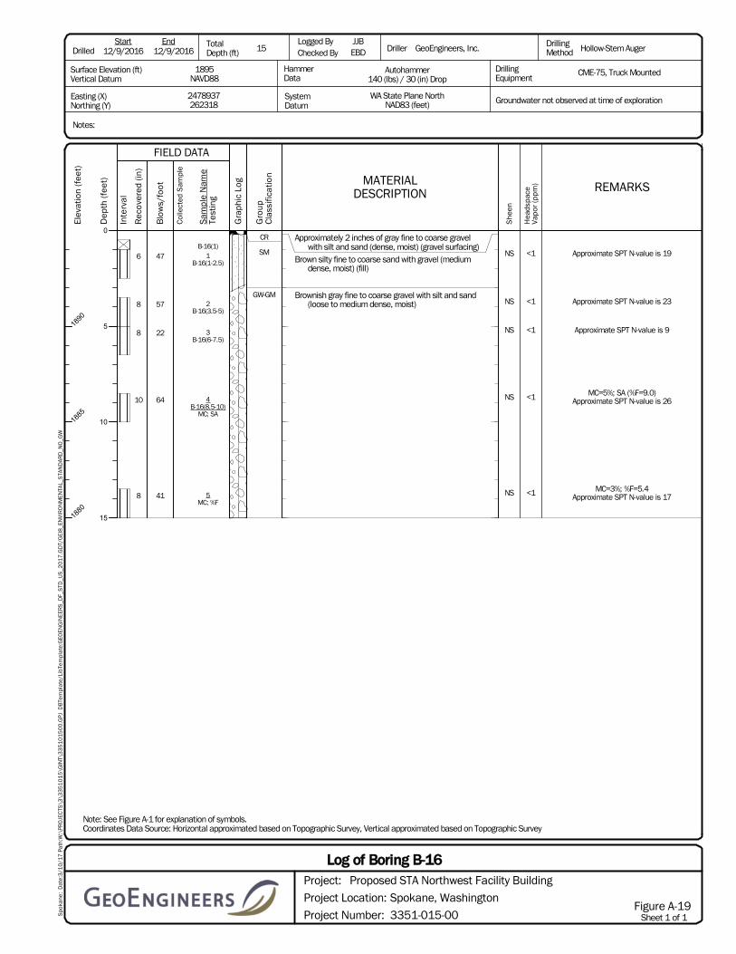
B-16(1)1
B-16(1-2.5)
2B-16(3.5-5)
3B-16(6-7.5)
4B-16(8.5-10)
MC; SA
5MC; %F
CR
SM
GW-GM
Approximately 2 inches of gray fine to coarse gravelwith silt and sand (dense, moist) (gravel surfacing)
Brown silty fine to coarse sand with gravel (mediumdense, moist) (fill)
Brownish gray fine to coarse gravel with silt and sand(loose to medium dense, moist)
6
8
8
10
8
47
57
22
64
41
NS
NS
NS
NS
NS
<1
<1
<1
<1
<1
Approximate SPT N-value is 19
Approximate SPT N-value is 23
Approximate SPT N-value is 9
MC=5%; SA (%F=9.0)Approximate SPT N-value is 26
MC=3%; %F=5.4Approximate SPT N-value is 17
Notes:
12/9/2016 12/9/2016 15JJBEBD GeoEngineers, Inc. Hollow-Stem Auger
CME-75, Truck MountedDrillingEquipment
Autohammer140 (lbs) / 30 (in) Drop
WA State Plane NorthNAD83 (feet)
2478937262318
1895NAVD88
Easting (X)Northing (Y)
Surface Elevation (ft)Vertical Datum
DrilledStart End Total
Depth (ft)Logged ByChecked By
HammerData
SystemDatum
Driller DrillingMethod
Groundwater not observed at time of exploration
Note: See Figure A-1 for explanation of symbols.Coordinates Data Source: Horizontal approximated based on Topographic Survey, Vertical approximated based on Topographic Survey
Spo
kane
: D
ate:
3/1
0/1
7 P
ath:
W:\
PRO
JEC
TS\3
\33
51
01
5\G
INT\
33
51
01
50
0.G
PJ D
BTe
mpl
ate/
LibT
empl
ate:
GEO
ENG
INEE
RS
_DF_
STD
_US
_20
17
.GD
T/G
EI8
_EN
VIR
ON
MEN
TAL_
STA
ND
ARD
_NO
_GW
Elev
atio
n (f
eet)
1890
1885
1880
Dep
th (f
eet)
0
5
10
15
Inte
rval
Gra
phic
Log
FIELD DATA
Sam
ple
Nam
eTe
stin
g
Col
lect
ed S
ampl
e
Gro
upC
lass
ifica
tion MATERIAL
DESCRIPTION
Rec
over
ed (i
n)
Blo
ws/
foot
Sheet 1 of 1Project Number:
Project Location:
Project:
Spokane, Washington
3351-015-00
Log of Boring B-16Proposed STA Northwest Facility Building
Figure A-19
She
en
Hea
dspa
ceVa
por
(ppm
) REMARKS
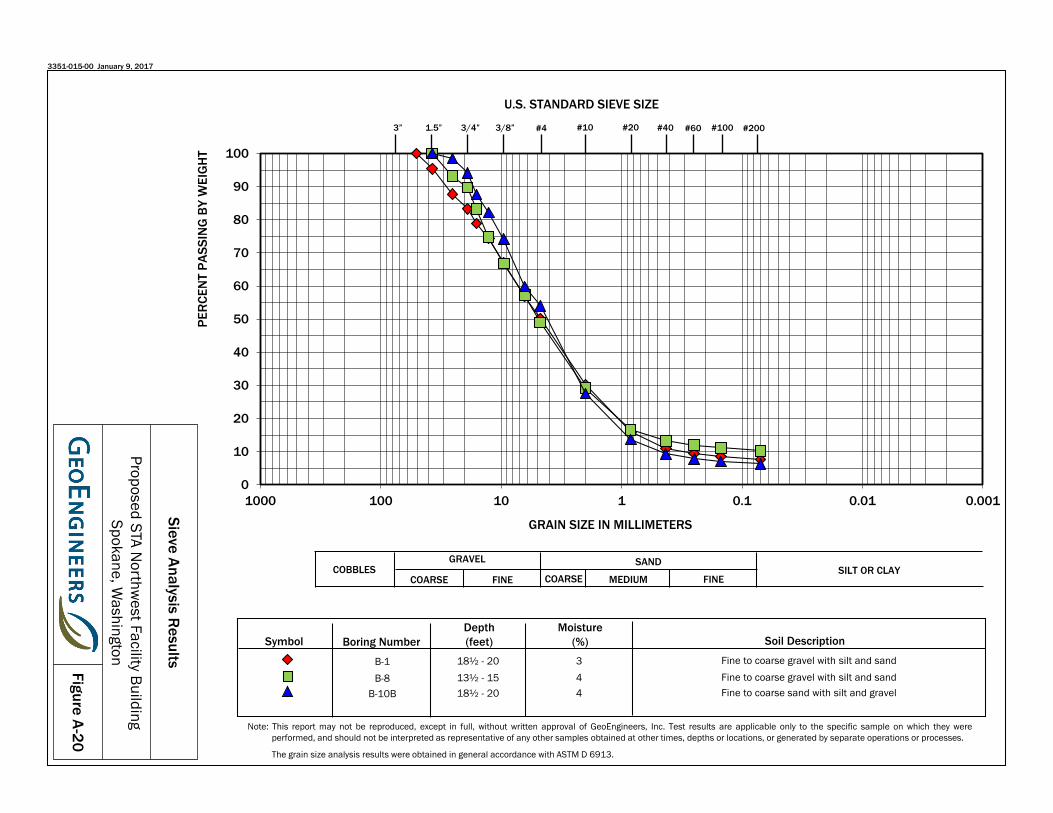
0
10
20
30
40
50
60
70
80
90
100
0.0010.010.11101001000
PER
CEN
T PA
SSIN
G B
Y W
EIG
HT
GRAIN SIZE IN MILLIMETERS
U.S. STANDARD SIEVE SIZE
SANDSILT OR CLAYCOBBLES
GRAVEL
COARSE MEDIUM FINECOARSE FINE
Boring NumberDepth(feet) Soil Description
B-1B-8
B-10B
18½ - 20 13½ - 15 18½ - 20
Fine to coarse gravel with silt and sandFine to coarse gravel with silt and sandFine to coarse sand with silt and gravel
SymbolMoisture
(%)344
3/8”3” 1.5” #4 #10 #20 #40 #60 #1003/4”
Figure A-20
Sieve Analysis Results
Proposed STA Northw
est Facility BuildingSpokane, W
ashington
3351-015-00 January 9, 2017
Note: This report may not be reproduced, except in full, without written approval of GeoEngineers, Inc. Test results are applicable only to the specific sample on which they wereperformed, and should not be interpreted as representative of any other samples obtained at other times, depths or locations, or generated by separate operations or processes.
The grain size analysis results were obtained in general accordance with ASTM D 6913.
#200

0
10
20
30
40
50
60
70
80
90
100
0.0010.010.11101001000
PER
CEN
T PA
SSIN
G B
Y W
EIG
HT
GRAIN SIZE IN MILLIMETERS
U.S. STANDARD SIEVE SIZE
SANDSILT OR CLAYCOBBLES
GRAVEL
COARSE MEDIUM FINECOARSE FINE
Boring NumberDepth(feet) Soil Description
B-13B-13B-14
8½ - 1023½ - 2513 – 15½
Fine to coarse gravel with sand and trace siltFine to coarse gravel with sand and trace siltFine to coarse gravel with sand and trace silt
SymbolMoisture
(%)332
3/8”3” 1.5” #4 #10 #20 #40 #60 #1003/4”
Figure A-21
Sieve Analysis Results
Proposed STA Northw
est Facility BuildingSpokane, W
ashington
3351-015-00 January 9, 2017
Note: This report may not be reproduced, except in full, without written approval of GeoEngineers, Inc. Test results are applicable only to the specific sample on which they wereperformed, and should not be interpreted as representative of any other samples obtained at other times, depths or locations, or generated by separate operations or processes.
The grain size analysis results were obtained in general accordance with ASTM D 6913.
#200

0
10
20
30
40
50
60
70
80
90
100
0.0010.010.11101001000
PER
CEN
T PA
SSIN
G B
Y W
EIG
HT
GRAIN SIZE IN MILLIMETERS
U.S. STANDARD SIEVE SIZE
SANDSILT OR CLAYCOBBLES
GRAVEL
COARSE MEDIUM FINECOARSE FINE
Boring NumberDepth(feet) Soil Description
B-15AB-15AB-16
8½ - 1013½ - 158½ - 10
Fine to coarse gravel with silt and sandFine to coarse gravel with sand and trace silt
Fine to coarse gravel with silt and sand
SymbolMoisture
(%)425
3/8”3” 1.5” #4 #10 #20 #40 #60 #1003/4”
Figure A-22
Sieve Analysis Results
Proposed STA Northw
est Facility BuildingSpokane, W
ashington
3351-015-00 January 9, 2017
Note: This report may not be reproduced, except in full, without written approval of GeoEngineers, Inc. Test results are applicable only to the specific sample on which they wereperformed, and should not be interpreted as representative of any other samples obtained at other times, depths or locations, or generated by separate operations or processes.
The grain size analysis results were obtained in general accordance with ASTM D 6913.
#200
APPENDIX B Historic Boring Logs


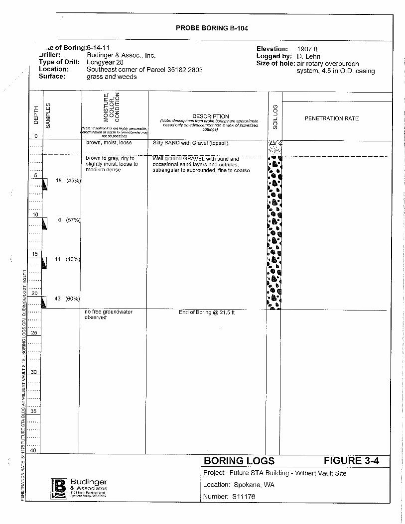
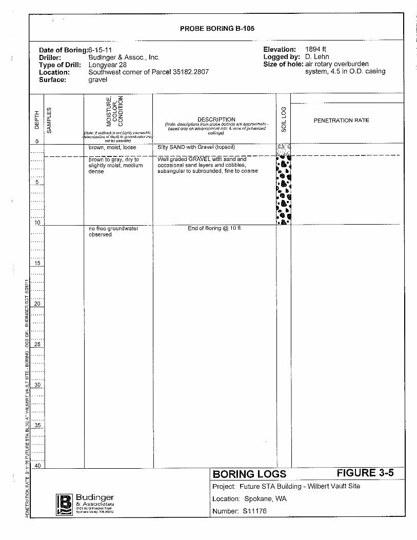


APPENDIX C Report Limitations and Guidelines for Use

April 6, 2017 | Page C-1 File No. 3351-015-00
APPENDIX C REPORT LIMITATIONS AND GUIDELINES FOR USE1
This appendix provides information to help you manage your risks with respect to the use of this report.
Read These Provisions Closely
It is important to recognize that the geoscience practices (geotechnical engineering, geology and environmental science) rely on professional judgment and opinion to a greater extent than other engineering and natural science disciplines, where more precise and/or readily observable data may exist. To help clients better understand how this difference pertains to our services, GeoEngineers includes the following explanatory “limitations” provisions in its reports. Please confer with GeoEngineers if you need to know more how these “Report Limitations and Guidelines for Use” apply to your project or site.
Geotechnical Services are Performed for Specific Purposes, Persons and Projects
This report has been prepared for Coffman Engineers, Inc. and for the project specifically identified in the report. The information contained herein is not applicable to other sites or projects.
GeoEngineers structures its services to meet the specific needs of its clients. No party other than the party to whom this report is addressed may rely on the product of our services unless we agree to such reliance in advance and in writing. Within the limitations of the agreed scope of services for the project, and its schedule and budget, our services have been executed in accordance with our Agreement with Coffman Engineers, Inc. dated October 31, 2016 and generally accepted geotechnical practices in this area at the time this report was prepared. We do not authorize, and will not be responsible for, the use of this report for any purposes or projects other than those identified in the report.
A Geotechnical Engineering or Geologic Report is based on a Unique Set of Project-Specific Factors
This report has been prepared for the proposed Spokane Transit Authority Northwest Facility Building located in Spokane, Washington. GeoEngineers considered a number of unique, project-specific factors when establishing the scope of services for this project and report. Unless GeoEngineers specifically indicates otherwise, it is important not to rely on this report if it was:
■ not prepared for you,
■ not prepared for your project,
■ not prepared for the specific site explored, or
■ completed before important project changes were made.
For example, changes that can affect the applicability of this report include those that affect:
■ the function of the proposed structure;
■ elevation, configuration, location, orientation or weight of the proposed structure;
1 Developed based on material provided by GBA, GeoProfessional Business Association; www.geoprofessional.org.

April 6, 2017 | Page C-2 File No. 3351-015-00
■ composition of the design team; or
■ project ownership.
If changes occur after the date of this report, GeoEngineers cannot be responsible for any consequences of such changes in relation to this report unless we have been given the opportunity to review our interpretations and recommendations. Based on that review, we can provide written modifications or confirmation, as appropriate.
Environmental Concerns are Not Covered
Unless environmental services were specifically included in our scope of services, this report does not provide any environmental findings, conclusions, or recommendations, including but not limited to, the likelihood of encountering underground storage tanks or regulated contaminants.
Subsurface Conditions Can Change
This geotechnical or geologic report is based on conditions that existed at the time the study was performed. The findings and conclusions of this report may be affected by the passage of time, by man-made events such as construction on or adjacent to the site, new information or technology that becomes available subsequent to the report date, or by natural events such as floods, earthquakes, slope instability or groundwater fluctuations. If more than a few months have passed since issuance of our report or work product, or if any of the described events may have occurred, please contact GeoEngineers before applying this report for its intended purpose so that we may evaluate whether changed conditions affect the continued reliability or applicability of our conclusions and recommendations.
Geotechnical and Geologic Findings are Professional Opinions
Our interpretations of subsurface conditions are based on field observations from widely spaced sampling locations at the site. Site exploration identifies the specific subsurface conditions only at those points where subsurface tests are conducted or samples are taken. GeoEngineers reviewed field and laboratory data and then applied its professional judgment to render an informed opinion about subsurface conditions at other locations. Actual subsurface conditions may differ, sometimes significantly, from the opinions presented in this report. Our report, conclusions and interpretations are not a warranty of the actual subsurface conditions.
Geotechnical Engineering Report Recommendations are Not Final
We have developed the following recommendations based on data gathered from subsurface investigation(s). These investigations sample just a small percentage of a site to create a snapshot of the subsurface conditions elsewhere on the site. Such sampling on its own cannot provide a complete and accurate view of subsurface conditions for the entire site. Therefore, the recommendations included in this report are preliminary and should not be considered final. GeoEngineers’ recommendations can be finalized only by observing actual subsurface conditions revealed during construction. GeoEngineers cannot assume responsibility or liability for the recommendations in this report if we do not perform construction observation.
We recommend that you allow sufficient monitoring, testing and consultation during construction by GeoEngineers to confirm that the conditions encountered are consistent with those indicated by the explorations, to provide recommendations for design changes if the conditions revealed during the work

April 6, 2017 | Page C-3 File No. 3351-015-00
differ from those anticipated, and to evaluate whether earthwork activities are completed in accordance with our recommendations. Retaining GeoEngineers for construction observation for this project is the most effective means of managing the risks associated with unanticipated conditions. If another party performs field observation and confirms our expectations, the other party must take full responsibility for both the observations and recommendations. Please note, however, that another party would lack our project-specific knowledge and resources.
A Geotechnical Engineering or Geologic Report Could Be Subject to Misinterpretation
Misinterpretation of this report by members of the design team or by contractors can result in costly problems. GeoEngineers can help reduce the risks of misinterpretation by conferring with appropriate members of the design team after submitting the report, reviewing pertinent elements of the design team’s plans and specifications, participating in pre-bid and preconstruction conferences, and providing construction observation.
Do Not Redraw the Exploration Logs
Geotechnical engineers and geologists prepare final boring and testing logs based upon their interpretation of field logs and laboratory data. The logs included in a geotechnical engineering or geologic report should never be redrawn for inclusion in architectural or other design drawings. Photographic or electronic reproduction is acceptable, but separating logs from the report can create a risk of misinterpretation.
Give Contractors a Complete Report and Guidance
To help reduce the risk of problems associated with unanticipated subsurface conditions, GeoEngineers recommends giving contractors the complete geotechnical engineering or geologic report, including these “Report Limitations and Guidelines for Use.” When providing the report, you should preface it with a clearly written letter of transmittal that:
■ advises contractors that the report was not prepared for purposes of bid development and that its accuracy is limited; and
■ encourages contractors to confer with GeoEngineers and/or to conduct additional study to obtain the specific types of information they need or prefer.
Contractors are Responsible for Site Safety on Their Own Construction Projects
Our geotechnical recommendations are not intended to direct the contractor’s procedures, methods, schedule or management of the work site. The contractor is solely responsible for job site safety and for managing construction operations to minimize risks to on-site personnel and adjacent properties.
Biological Pollutants
GeoEngineers’ Scope of Work specifically excludes the investigation, detection, prevention or assessment of the presence of Biological Pollutants. Accordingly, this report does not include any interpretations, recommendations, findings or conclusions regarding the detecting, assessing, preventing or abating of Biological Pollutants, and no conclusions or inferences should be drawn regarding Biological Pollutants as they may relate to this project. The term “Biological Pollutants” includes, but is not limited to, molds, fungi, spores, bacteria and viruses, and/or any of their byproducts.

April 6, 2017 | Page C-4 File No. 3351-015-00
A Client that desires these specialized services is advised to obtain them from a consultant who offers services in this specialized field.
Information Provided by Others
GeoEngineers has relied upon certain data or information provided or compiled by others in the performance of our services. Although we use sources that we reasonably believe to be trustworthy, GeoEngineers cannot warrant or guarantee the accuracy or completeness of information provided or compiled by others.

Have we delivered World Class Client Service?
Please let us know by visiting www.geoengineers.com/feedback.

tbecker
Typewritten Text
THIS PAGE INTENTIONALLY LEFT BLANK

Spokane Transit Authority Section 007500 Boone NW Garage Environmental Assessment
November 19, 2017 007500 - 1
SECTION 007500 - ENVIRONMENTAL ASSESSMENT AND SUPPLEMENTAL LIMITED PHASE II ENVIRONMENTAL SITE ASSESSMENT
PART 1 - GENERAL
1.1 ENVIRONMENTAL ASSESSMENT AND SUPPLEMENTAL LIMITED PHASE II ENVIRONMENTAL SITE ASSESSMENT
A. These Documents with their referenced attachments are part of the Procurement and Contracting Requirements for Project. They provide Owner's information for Bidders' convenience and are intended to supplement rather than serve in lieu of Bidders' own investigations. They are made available for Bidders' convenience and information, but are not a warranty of existing conditions. These Documents and their attachments are not part of the Contract Documents.
B. An environmental assessment report prepared by GeoEngineers, dated February 14, 2017 and a supplemental limited Phase II Environmental Site Assessment Report, prepared by GeoEngineers, dated May 12, 2017 are available to be viewed at the office of Coffman Engineers, 10 N Post Street, Suite 500, Spokane WA 99201, phone 509-328-2994, contact: Carsten Mortenson.
C. A site plan labeled Figure 2, prepared by GeoEngineers illustrating estimated contaminated soil areas and depths is bound in the Project Manual.
PART 2 – PRODUCTS (Not used)
PART 3 – EXECUTION (Not used)
END OF SECTION 007500

Spokane Transit Authority Section 007500 Boone NW Garage Environmental Assessment
November 19, 2017 007500 - 2
THIS PAGE INTENTIONALLY LEFT BLANK
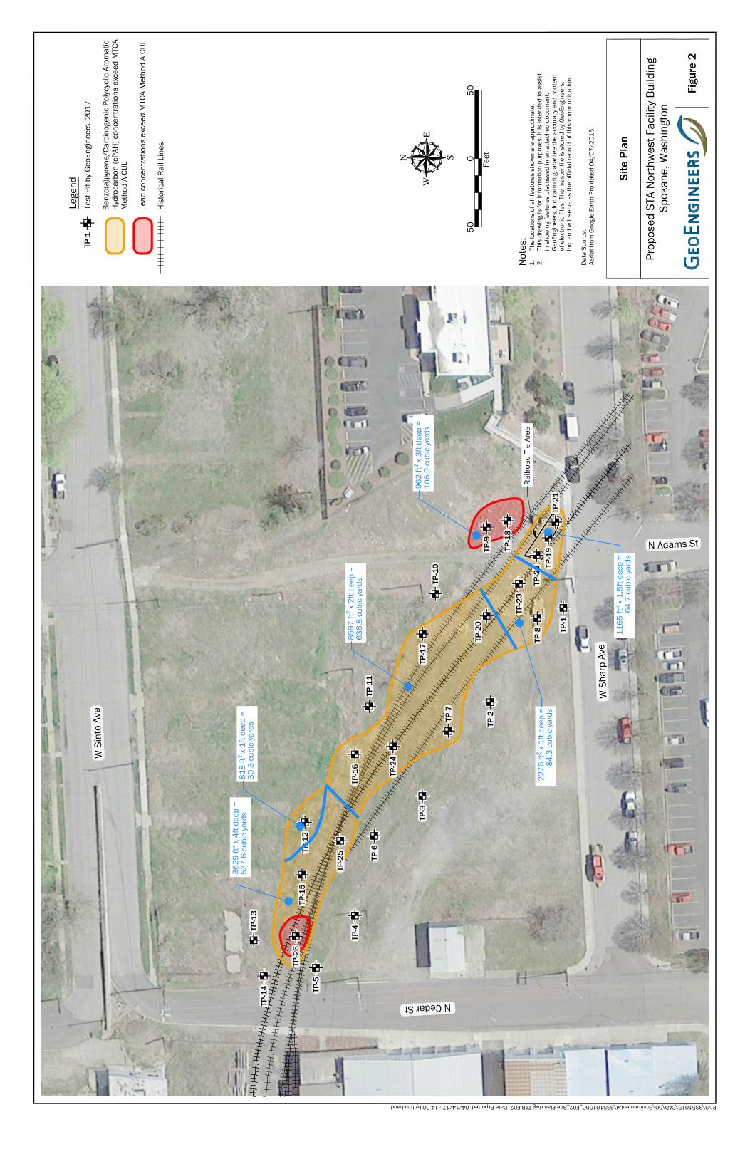
W S
harp
Ave
N Adams St
N Cedar St
W S
into
Ave
Railr
oad
Tie
Area
TP-1
TP-8
TP-9
TP-2TP
-7
TP-3
TP-6
TP-4
TP-5
TP-1
8TP
-23
TP-2
0
TP-1
0TP
-17
TP-2
4
TP-1
6TP
-11
TP-2
5TP-1
2TP
-15
TP-2
6
TP-1
4TP
-13
TP-1
9TP
-22
TP-2
1
962
ft2 x 3
ft de
ep =
106.
9 cu
bic
yard
s
8597
ft2 x
2ft
deep
=63
6.8
cubi
c ya
rds
3629
ft2 x
4ft
deep
=53
7.6
cubi
c ya
rds
818
ft2 x 1
ft de
ep =
30.3
cub
ic y
ards
2276
ft2 x
1ft
deep
=84
.3 c
ubic
yar
ds
1165
ft2 x
1.5
ft de
ep =
64.7
cub
ic y
ards
Figu
re 2
Prop
osed
STA
Nor
thw
est F
acili
ty B
uild
ing
Spok
ane,
Was
hing
ton
Site
Pla
n
WE
N S
Lege
nd
Not
es:
1.Th
e lo
catio
ns o
f all
feat
ures
sho
wn
are
appr
oxim
ate.
2.Th
is d
raw
ing
is fo
r inf
orm
atio
n pu
rpos
es. I
t is
inte
nded
to a
ssis
tin
sho
win
g fe
atur
es d
iscu
ssed
in a
n at
tach
ed d
ocum
ent.
Geo
Engi
neer
s, In
c. c
anno
t gua
rant
ee th
e ac
cura
cy a
nd c
onte
ntof
ele
ctro
nic
files
. The
mas
ter f
ile is
sto
red
by G
eoEn
gine
ers,
Inc.
and
will
ser
ve a
s th
e of
ficia
l rec
ord
of th
is c
omm
unic
atio
n.
Dat
a So
urce
:Ae
rial f
rom
Goo
gle
Earth
Pro
dat
ed 0
4/07
/201
6.
Feet
050
50
P:\3\3351015\CAD\00\Environmental\335101500_F02_Site Plan.dwg TAB:F02 Date Exported: 04/14/17 - 14:00 by tmichaud
TP-1
Test
Pit
by G
eoEn
gine
ers,
201
7
Benz
o(a)
pyre
ne/C
arci
noge
nic
Poly
cycl
ic A
rom
atic
Hyd
roca
rbon
(cPA
H) c
once
ntra
tions
exc
eed
MTC
AM
etho
d A
CUL
Lead
con
cent
ratio
ns e
xcee
d M
TCA
Met
hod
A CU
L
His
toric
al R
ail L
ines

tbecker
Typewritten Text
tbecker
Typewritten Text
THIS PAGE INTENTIONALLY LEFT BLANK
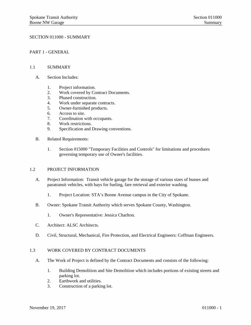
Spokane Transit Authority Section 011000 Boone NW Garage Summary
November 19, 2017 011000 - 1
SECTION 011000 - SUMMARY
PART 1 - GENERAL
1.1 SUMMARY
A. Section Includes:
1. Project information. 2. Work covered by Contract Documents. 3. Phased construction. 4. Work under separate contracts. 5. Owner-furnished products. 6. Access to site. 7. Coordination with occupants. 8. Work restrictions. 9. Specification and Drawing conventions.
B. Related Requirements:
1. Section 015000 "Temporary Facilities and Controls" for limitations and procedures governing temporary use of Owner's facilities.
1.2 PROJECT INFORMATION
A. Project Information: Transit vehicle garage for the storage of various sizes of busses and paratransit vehicles, with bays for fueling, fare retrieval and exterior washing.
1. Project Location: STA’s Boone Avenue campus in the City of Spokane.
B. Owner: Spokane Transit Authority which serves Spokane County, Washington.
1. Owner's Representative: Jessica Charlton.
C. Architect: ALSC Architects.
D. Civil, Structural, Mechanical, Fire Protection, and Electrical Engineers: Coffman Engineers.
1.3 WORK COVERED BY CONTRACT DOCUMENTS
A. The Work of Project is defined by the Contract Documents and consists of the following:
1. Building Demolition and Site Demolition which includes portions of existing streets and parking lot.
2. Earthwork and utilities. 3. Construction of a parking lot.

Spokane Transit Authority Section 011000 Boone NW Garage Summary
November 19, 2017 011000 - 2
4. Construction of a garage building for storage of Spokane Transit Authority vehicles with fueling and washing facilities.
1.4 PHASED CONSTRUCTION
A. The Work shall be conducted in two phases, with each phase substantially complete as indicated.
1. Phase 1: Excludes work on the entire existing STA employee parking lot until staff parking can occupy the new Northeast Parking Lot. Access and egress from the lot must be maintained.
2. Phase 2: All remaining construction.
1.5 WORK UNDER SEPARATE CONTRACTS
A. Chain Link fencing around the Northeast Parking Lot.
1.6 OWNER-FURNISHED PRODUCTS
A. Owner will furnish products indicated. The Work includes receiving, unloading, handling, storing, and protecting Owner-furnished products and making plumbing, mechanical, and electrical connections.
B. Owner-Furnished Products:
1. Bus Washing System equipment.
C. Owner Responsibilities:
1. Owner will arrange and pay for delivery of items according to Contractor’s Construction Schedule.
2. After delivery, Owner will inspect delivered items for damage. Contractor shall be present for and assist in Owner’s inspection.
3. If Owner-furnished items are damaged, defective, or missing, Owner will arrange for replacement.
D. Contractor Responsibilities:
1. Contractor shall install and otherwise incorporate Owner-furnished items into the Work. 2. Contractor will arrange and pay for manufacturer’s field services and for delivery of
manufacturer’s warranties. Allowance for field services is $39,900. Contact is Don Schiedel, office phone 1-866-747-4567 ext. 117, cell phone 1-716-289-2980, email [email protected].
3. Contractor shall review Shop Drawings, Product Data, and Samples and return them to Architect noting discrepancies or anticipated problems in use of product.
4. Contractor is responsible for receiving, unloading, and handling Owner-furnished items at Project site.

Spokane Transit Authority Section 011000 Boone NW Garage Summary
November 19, 2017 011000 - 3
5. Owner will furnish Contractor the earliest possible delivery date for Owner-furnished products. Contractor shall verify delivery dates with the manufacturer before designating dates of Owner-furnished items in Contractor’s Construction Schedule.
6. Contractor is responsible for protecting Owner-furnished items from damage during storage and handling, including damage from exposure to the elements.
7. If Owner-furnished items are damaged as a result of Contractor’s operations, Contractor shall repair or replace them.
1.7 ACCESS TO SITE
A. General: Contractor shall have limited use of Project site for construction operations as indicated on Drawings by the Contract limits and as indicated by requirements of this Section.
B. Use of Site: Limit use of Project site to Work in areas indicated. Do not disturb portions of Project site beyond areas in which the Work is indicated.
1. Driveways, Walkways and Entrances: Keep driveways and entrances serving premises clear and available to Owner, Owner's employees, and emergency vehicles at all times. Do not use these areas for parking or for storage of materials.
2. Provide not less than 72 hours’ notice to Owner of activities that will affect Owner’s operations
1.8 COORDINATION WITH OCCUPANTS
A. Maintain access and egress from the existing employee lot during Phase 1 and from STA North / Administration Building to / from Adams Street during the entire construction period.
B. Owner Limited Occupancy of Completed Areas of Construction: Owner reserves the right to occupy and to place and install equipment in completed portions of the Work, prior to Substantial Completion of the Work, provided such occupancy does not interfere with completion of the Work. Such placement of equipment and limited occupancy shall not constitute acceptance of the total Work.
1. Architect will prepare a Certificate of Substantial Completion for each specific portion of the Work to be occupied prior to Owner acceptance of the completed Work.
2. Obtain a Certificate of Occupancy from authorities having jurisdiction before full Owner occupancy.
3. Before limited Owner occupancy, electrical systems shall be fully operational, and required tests and inspections shall be successfully completed. On occupancy, Owner will operate and maintain electrical systems serving occupied portions of Work.
4. On occupancy, Owner will assume responsibility for maintenance and custodial service for occupied portions of Work.
1.9 WORK RESTRICTIONS
A. Work Restrictions, General: Comply with restrictions on construction operations.

Spokane Transit Authority Section 011000 Boone NW Garage Summary
November 19, 2017 011000 - 4
1. Comply with limitations on use of public streets and with other requirements of authorities having jurisdiction.
B. Existing Utility Interruptions: Do not interrupt utilities serving facilities occupied by Owner or others unless permitted under the following conditions and then only after providing temporary utility services according to requirements indicated:
1. Notify Owner not less than two days in advance of proposed utility interruptions. 2. Obtain Owner's written permission before proceeding with utility interruptions.
C. Restricted Substances: Use of tobacco products and other controlled substances on Project site is not permitted.
1.10 SPECIFICATION AND DRAWING CONVENTIONS
A. Specification Format: Specifications are organized into Divisions and Sections using CSI/CSC’s MasterFormat latest edition numbering system. 1. Section identification: Specifications use Section numbers and titles to help cross-
referencing in the Contract Documents. Sections in the Project Manual are in numeric sequence; however, the sequence is incomplete because all available Section numbers are not used. Consult the table of contents at the beginning of the Project Manual to determine numbers and names of Sections in the Contract Documents.
B. Specification Content: The Specifications use certain conventions for the style of language and the intended meaning of certain terms, words, and phrases when used in particular situations. These conventions are as follows:
1. Imperative mood and streamlined language are generally used in the Specifications. The words "shall," "shall be," or "shall comply with," depending on the context, are implied where a colon (:) is used within a sentence or phrase. Occasionally the indicative or subjunctive mood may be used in the Section Text for clarity to describe responsibilities that must be fulfilled indirectly by Contractor or by others when so noted.
2. Specification requirements are to be performed by Contractor unless specifically stated otherwise.
3. Abbreviated Language: Language used in the Specifications and other Contract Documents may be abbreviated. Words and meaning shall be interpreted as appropriate. Words implied, but not stated, shall be inferred as the sense requires. Singular words shall be interpreted as plural, and plural words shall be interpreted as singular where applicable as the context of the Contract Documents indicates.
C. Division 01 General Requirements: Requirements of Sections in Division 01 apply to the Work of all Sections in the Specifications.
D. Drawing Coordination: Requirements for materials and products identified on Drawings are described in detail in the Specifications. One or more of the following are used on Drawings to identify materials and products:
1. Terminology: Materials and products are identified by the typical generic terms used in the individual Specifications Sections.

Spokane Transit Authority Section 011000 Boone NW Garage Summary
November 19, 2017 011000 - 5
2. Abbreviations: Materials and products are identified by abbreviations scheduled on Drawings.
3. Keynoting: Materials and products are identified by reference keynotes referencing Specification Section numbers found in this Project Manual.
PART 2 - PRODUCTS (Not Used)
PART 3 - EXECUTION (Not Used)
END OF SECTION 011000

Spokane Transit Authority Section 011000 Boone NW Garage Summary
November 19, 2017 011000 - 6
THIS PAGE INTENTIONALLY LEFT BLANK

Spokane Transit Authority Section 012100 Boone NW Garage Allowances
November 19, 2017 012100 - 1
SECTION 012100 - ALLOWANCES
PART 1 - GENERAL
1.1 RELATED DOCUMENTS
A. Drawings and general provisions of the Contract, including General and Supplementary Conditions and other Division 01 Specification Sections, apply to this Section.
1.2 SUMMARY
A. Section includes administrative and procedural requirements governing allowances.
B. Types of allowances include the following:
1. Lump-sum allowances.
1.3 DEFINITIONS
A. Allowance is a quantity of work or dollar amount established in lieu of additional requirements, used to defer selection of actual materials and equipment to a later date when direction will be provided to Contractor. If necessary, additional requirements will be issued by Change Order.
1.4 SELECTION AND PURCHASE
A. At the earliest practical date after award of the Contract, advise Architect of the date when final selection, or purchase and delivery, of each product or system described by an allowance must be completed by the Owner to avoid delaying the Work.
1.5 INFORMATIONAL SUBMITTALS
A. Submit invoices or delivery slips to show actual quantities of materials delivered to the site for use in fulfillment of each allowance.
B. Coordinate and process submittals for allowance items in same manner as for other portions of the Work.
1.6 LUMP-SUM ALLOWANCES
A. Allowance shall include cost to Contractor of specific services ordered by Owner under allowance.

Spokane Transit Authority Section 012100 Boone NW Garage Allowances
November 19, 2017 012100 - 2
1.7 ADJUSTMENT OF ALLOWANCES
A. Submit claims for increased costs because of a change in scope or nature of the allowance described in the Contract Documents.
1. Do not include Contractor's or subcontractor's indirect expense in the Change Order cost amount unless it is clearly shown that the nature or extent of Work has changed from what could have been foreseen from information in the Contract Documents.
PART 2 - PRODUCTS (Not Used)
PART 3 - EXECUTION
3.1 SCHEDULE OF ALLOWANCES
A. Allowance No. 1: Lump-Sum Allowance: Include the sum of $39,900 for bus washer manufacturer’s field services that include consultation, site visit during installation, startup and commissioning. Contact is Don Schiedel, office phone: 1-866-747-4567, cell: 716-289-2980, email: [email protected].
END OF SECTION 012100

Spokane Transit Authority Section 012200
Boone NW Garage Unit Prices
November 19, 2017 012200 - 1
SECTION 012200 - UNIT PRICES
PART 1 - GENERAL
1.1 RELATED DOCUMENTS
A. Drawings and general provisions of the Contract, including General and Supplementary
Conditions and other Division 01 Specification Sections, apply to this Section.
1.2 SUMMARY
A. Section includes administrative and procedural requirements for unit prices.
B. Related Requirements:
1. Section 014000 "Quality Requirements" for field testing by an independent testing
agency.
1.3 DEFINITIONS
A. Unit price is an amount incorporated into the Agreement, applicable during the duration of the
Work as a price per unit of measurement for materials, equipment, or services, or a portion of
the Work, added to or deducted from the Contract Sum by appropriate modification, if the scope
of Work or estimated quantities of Work required by the Contract Documents are increased or
decreased.
1.4 PROCEDURES
A. Unit prices include all necessary material, plus cost for delivery, installation, insurance,
applicable taxes, overhead, and profit.
B. Owner reserves the right to reject Contractor's measurement of work-in-place that involves use
of established unit prices and to have this work measured, at Owner's expense, by an
independent surveyor acceptable to Contractor.
C. List of Unit Prices: A schedule of unit prices is included in Part 3. Specification Sections
referenced in the schedule contain requirements for materials described under each unit price.
Spokane Transit Authority Section 012200
Boone NW Garage Unit Prices
November 19, 2017 012200 - 2
PART 2 - PRODUCTS (Not Used)
PART 3 - EXECUTION
3.1 SCHEDULE OF UNIT PRICES
A. Unit Price No. 1: Remove uncontaminated soil designated by the Owner to be unsatisfactory
and replace with Structural Fill.
1. Description: Uncontaminated, unsatisfactory soil excavation and disposal off-site and
replacement with satisfactory fill material or engineered fill from off-site, as required,
according to Section 312000 "Earth Moving" and the Geo-Technical Report.
2. Unit of Measurement: Cubic yard of soil excavated, based on in-place surveys of volume
before and after removal.
END OF SECTION 012200
Spokane Transit Authority Section 012300 Boone NW Garage Alternates
November 19, 2017 012300 - 1
SECTION 012300 - OPTIONS
PART 1 - GENERAL
1.1 RELATED DOCUMENTS
A. Drawings and general provisions of the Contract, including General and Supplementary Conditions and other Division 01 Specification Sections, apply to this Section.
1.2 SUMMARY
A. Section includes administrative and procedural requirements for options.
1.3 DEFINITIONS
A. Option: An amount proposed by bidders and stated on the Bid Form for certain work defined in the bidding requirements that may be added to the base bid amount if the Owner decides to accept a corresponding change either in the amount of construction to be completed or in the products, materials, equipment, systems, or installation methods described in the Contract Documents.
1. Options described in this Section are part of the Work only if enumerated in the Agreement.
2. The cost or credit for each option is the net addition from the Contract Sum to incorporate options into the Work. No other adjustments are made to the Contract Sum.
1.4 PROCEDURES
A. Coordination: Revise or adjust affected adjacent work as necessary to completely integrate work of the option into Project.
1. Include as part of each option, miscellaneous devices, accessory objects, and similar items incidental to or required for a complete installation whether or not indicated as part of option.
B. Execute accepted options under the same conditions as other work of the Contract.
C. Schedule: A schedule of options is included at the end of this Section. Specification Sections referenced in schedule contain requirements for materials necessary to achieve the work described under each option.

Spokane Transit Authority Section 012300 Boone NW Garage Alternates
November 19, 2017 012300 - 2
PART 2 - PRODUCTS (Not Used)
PART 3 - EXECUTION
3.1 SCHEDULE OF OPTIONS
A. Option No. 1 – Photovoltaic Roof Panels
1. Provide pricing for the design and installation of a 100KW grid tied photovoltaic system on the south sloping portion of the NW Garage roof. The photovoltaic system shall be roof mounted utilizing a flat rail system that attaches to the standing seam metal roof system with S-5 mounting clips. No attachment penetration through the metal roof is allowed. The photovoltaic modules shall be either 60 or 72 cell monocrystalline. The photovoltaic system shall utilize 480V, 3-phase microinverter technology, either Enphase, APsysytems or approved.
END OF SECTION 012300
Spokane Transit Authority Section 012500
Boone NW Garage Substitution Procedures
November 19, 2017 012500 - 1
SECTION 012500 - SUBSTITUTION PROCEDURES
PART 1 - GENERAL
1.1 SUMMARY
A. Section includes administrative and procedural requirements for substitutions.
B. Related Requirements:
1. Section 016000 "Product Requirements" for requirements for submitting comparable
product submittals for products by listed manufacturers.
1.2 DEFINITIONS
A. Substitutions: Changes in products, materials, equipment, and methods of construction from
those required by the Contract Documents and proposed by Contractor.
1.3 ACTION SUBMITTALS
A. Substitution Requests: Submit three copies of each request for consideration. Identify product or
fabrication or installation method to be replaced. Include Specification Section number and title
and Drawing numbers and titles.
1. Substitution Request Form: Use form provided in Project Manual.
2. Documentation: Show compliance with requirements for substitutions and the following,
as applicable:
a. Statement indicating why specified product or fabrication or installation cannot be
provided, if applicable.
b. Coordination information, including a list of changes or revisions needed to other
parts of the Work and to construction performed by Owner and separate
contractors, that will be necessary to accommodate proposed substitution.
c. Detailed comparison of significant qualities of proposed substitution with those of
the Work specified. Include annotated copy of applicable Specification Section.
Significant qualities may include attributes such as performance, weight, size,
durability, visual effect, sustainable design characteristics, warranties, and specific
features and requirements indicated. Indicate deviations, if any, from the Work
specified.
d. Product Data, including drawings and descriptions of products and fabrication and
installation procedures.
e. Samples, where applicable or requested.
f. Certificates and qualification data, where applicable or requested.
g. List of similar installations for completed projects with project names and
addresses and names and addresses of architects and owners.
h. Material test reports from a qualified testing agency indicating and interpreting test
results for compliance with requirements indicated.
i. Research reports evidencing compliance with building code in effect for Project,
from a model code organization acceptable to aurhorities having jurisdiction.

Spokane Transit Authority Section 012500
Boone NW Garage Substitution Procedures
November 19, 2017 012500 - 2
j. Detailed comparison of Contractor's construction schedule using proposed
substitution with products specified for the Work, including effect on the overall
Contract Time. If specified product or method of construction cannot be provided
within the Contract Time, include letter from manufacturer, on manufacturer's
letterhead, stating date of receipt of purchase order, lack of availability, or delays
in delivery.
k. Cost information, including a proposal of change, if any, in the Contract Sum.
l. Contractor's certification that proposed substitution complies with requirements in
the Contract Documents except as indicated in substitution request, is compatible
with related materials, and is appropriate for applications indicated.
m. Contractor's waiver of rights to additional payment or time that may subsequently
become necessary because of failure of proposed substitution to produce indicated
results.
3. Architect's Action: If necessary, Architect will request additional information or
documentation for evaluation within seven days of receipt of a request for substitution.
Architect will notify Contractor of acceptance or rejection of proposed substitution within
15 days of receipt of request, or 7 days of receipt of additional information or
documentation, whichever is later.
a. Forms of Acceptance: Change Order, Construction Change Directive, or
Architect's Supplemental Instructions for minor changes in the Work.
4. Use product specified if Architect does not issue a decision on use of a proposed
substitution within time allocated.
1.4 QUALITY ASSURANCE
A. Compatibility of Substitutions: Investigate and document compatibility of proposed substitution
with related products and materials. Engage a qualified testing agency to perform compatibility
tests recommended by manufacturers.
PART 2 - PRODUCTS
2.1 SUBSTITUTIONS
A. Substitutions for Cause: Submit requests for substitution immediately on discovery of need for
change, but not later than 15 days prior to time required for preparation and review of related
submittals.
1. Conditions: Architect will consider Contractor's request for substitution when the
following conditions are satisfied:
a. Requested substitution is consistent with the Contract Documents and will produce
indicated results.
b. Requested substitution offers Owner a substantial advantage in cost, time, energy
conservation, or other considerations, after deducting additional responsibilities
Owner must assume. Owner’s additional responsibilities may include
compensation to Architect for redesign and evaluation services, increased cost of
other construction by Owner, and similar considerations.
c. Requested substitution does not require extensive revisions to the Contract
Documents or Work already in place.
d. Substitution request is fully documented and properly submitted.

Spokane Transit Authority Section 012500
Boone NW Garage Substitution Procedures
November 19, 2017 012500 - 3
e. Requested substitution will not adversely affect Contractor's construction schedule.
f. Requested substitution has received necessary approvals of authorities having
jurisdiction.
g. Requested substitution is compatible with other portions of the Work.
h. Requested substitution has been coordinated with other portions of the Work.
i. Requested substitution provides specified warranty.
j. If requested substitution involves more than one contractor, requested substitution
has been coordinated with other portions of the Work, is uniform and consistent, is
compatible with other products, and is acceptable to all contractors involved.
B. Substitutions for Convenience: Not allowed.
PART 3 - EXECUTION (Not Used)
END OF SECTION 012500

Spokane Transit Authority Section 012500
Boone NW Garage Substitution Procedures
November 19, 2017 012500 - 4
THIS PAGE INTENTIONALLY LEFT BLANK
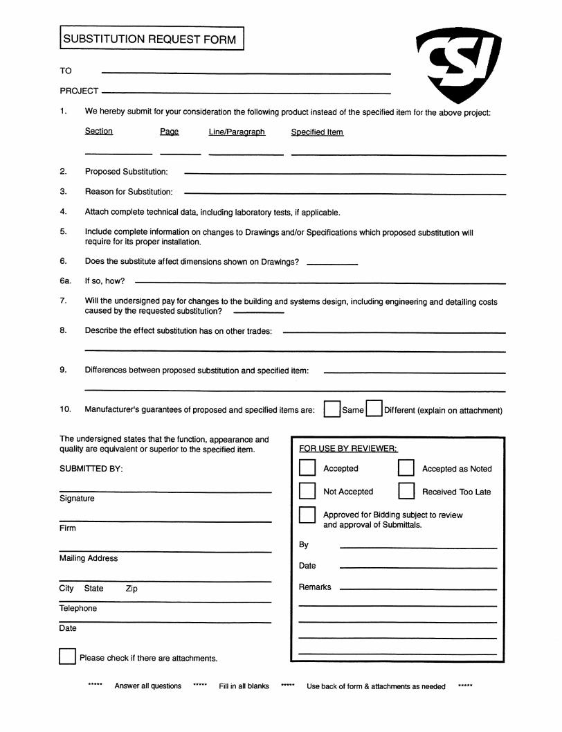

tbecker
Typewritten Text
THIS PAGE INTENTIONALLY LEFT BLANK
tbecker
Typewritten Text
tbecker
Typewritten Text
tbecker
Typewritten Text
tbecker
Typewritten Text
tbecker
Typewritten Text
tbecker
Typewritten Text

Spokane Transit Authority Section 013100
Boone NW Garage Project Management And Coordination
November 19, 2017 013100 - 1
SECTION 013100 - PROJECT MANAGEMENT AND COORDINATION
PART 1 - GENERAL
1.1 SUMMARY
A. Section includes administrative provisions for coordinating construction operations on
Project including, but not limited to, the following:
1. Coordination drawings.
2. Requests for Information (RFIs).
3. Administrative and supervisory personnel.
4. Project meetings.
B. Related Requirements:
1. Section 013200 “Construction Progress Documentation” for preparing and
submitting contractor’s Construction Schedule.
2. Section 017300 "Execution" for procedures for coordinating general installation
and field-engineering services, including establishment of benchmarks and
control points.
1.2 DEFINITIONS
A. RFI: Request from Contractor seeking information required by or clarifications of the
Contract Documents.
1.3 GENERAL COORDINATION PROCEDURES
A. Coordination: Coordinate construction operations included in different Sections of the
Specifications to ensure efficient and orderly installation of each part of the Work.
Coordinate construction operations, included in different Sections, that depend on each
other for proper installation, connection, and operation.
1. Schedule construction operations in sequence required to obtain the best results
where installation of one part of the Work depends on installation of other
components, before or after its own installation.
2. Coordinate installation of different components to ensure maximum performance
and accessibility for required maintenance, service, and repair.
3. Make adequate provisions to accommodate items scheduled for later installation.
4. Where availability of space is limited, coordinate installation of different
components to ensure maximum performance and accessibility for required
maintenance, service, and repair of all components, including mechanical and
electrical.

Spokane Transit Authority Section 013100
Boone NW Garage Project Management And Coordination
November 19, 2017 013100 - 2
B. Prepare memoranda for distribution to each party involved, outlining special procedures
required for coordination. Include such items as required notices, reports, and list of
attendees at meetings.
1. Prepare similar memoranda for Owner and separate contractors if coordination of
their Work is required.
C. Administrative Procedures: Coordinate scheduling and timing of required
administrative procedures with other construction activities and activities of other
contractors to avoid conflicts and to ensure orderly progress of the Work. Such
administrative activities include, but are not limited to, the following:
1. Preparation of Contractor's construction schedule.
2. Preparation of the schedule of values.
3. Installation and removal of temporary facilities and controls.
4. Delivery and processing of submittals.
5. Progress meetings.
6. Preinstallation conferences.
7. Project closeout activities.
8. Startup and adjustment of systems.
D. Conservation: Coordinate construction activities to ensure that operations are carried
out with consideration given to conservation of energy, water, and materials.
1. Salvage materials and equipment involved in performance of, but not actually
incorporated into, the Work. Refer to other Sections for disposition of salvaged
materials that are designated as Owner’s property.
1.4 COORDINATION DRAWINGS
A. Coordination Drawings, General: Prepare coordination drawings according to
requirements in individual Sections, where installation is not completely shown on Shop
Drawings, where limited space availability necessitates coordination, or if coordination
is required to facilitate integration of products and materials fabricated or installed by
more than one entity.
1. Content: Project-specific information, drawn accurately to a scale large enough to
indicate and resolve conflicts. Do not base coordination drawings on standard
printed data. Include the following information, as applicable:
a. Indicate functional and spatial relationships of components of architectural,
structural, civil, mechanical, and electrical systems.
b. Indicate required installation sequences.
c. Indicate dimensions shown on the Drawings. Specifically note dimensions
that appear to be in conflict with submitted equipment and minimum
clearance requirements. Provide alternate sketches to Architect indicating
proposed resolution of such conflicts. Minor dimension changes and
difficult installations will not be considered changes to the Contract.
2. Submittal: Electronic documents preferred.
3. Sheet Size: Minimum 8-1/2 by 11 inches but no larger than 24 by 36 inches.
Spokane Transit Authority Section 013100
Boone NW Garage Project Management And Coordination
November 19, 2017 013100 - 3
4. Refer to individual Sections for Coordination Drawing requirements for Work in
those Sections.
1.5 REQUESTS FOR INFORMATION (RFIs)
A. General: Immediately on discovery of the need for additional information or
interpretation of the Contract Documents, and if not possible to request interpretation at
Project meeting, Contractor shall prepare and submit an RFI in the form specified.
1. Architect will return RFIs submitted to Architect by other entities controlled by
Contractor with no response.
2. Coordinate and submit RFIs in a prompt manner so as to avoid delays in
Contractor's work or work of subcontractors.
B. Content of the RFI: Include a detailed, legible description of item needing information
or interpretation and the following:
1. Project name.
2. Project number.
3. Date.
4. Name of Contractor.
5. Name of Architect.
6. RFI number, numbered sequentially.
7. RFI subject.
8. Specification Section number and title and related Articles, paragraphs, and
subparagraphs, as appropriate.
9. Drawing number and detail references, as appropriate.
10. Field dimensions and conditions, as appropriate.
11. Contractor's suggested resolution. If Contractor's solution(s) impacts the Contract
Time or the Contract Sum, Contractor shall state impact in the RFI.
12. Contractor's signature.
13. Attachments: Include sketches, descriptions, measurements, photos, Product Data,
Shop Drawings, coordination drawings, and other information necessary to fully
describe items needing interpretation.
a. Supplementary drawings prepared by Contractor shall include dimensions,
thicknesses, structural grid references, and details of affected materials,
assemblies, and attachments.
C. Architect's Action: Architect will review each RFI, determine action required, and
respond. Allow seven working days for Architect's response for each RFI.
1. The following RFIs will be returned without action:
a. Requests for approval of submittals.
b. Requests for approval of substitutions.
c. Requests for coordination information already indicated in the Contract
Documents.
d. Requests for adjustments in the Contract Time or the Contract Sum.
e. Requests for interpretation of Architect's actions on submittals.
f. Incomplete RFIs or inaccurately prepared RFIs.

Spokane Transit Authority Section 013100
Boone NW Garage Project Management And Coordination
November 19, 2017 013100 - 4
2. Architect's action may include a request for additional information, in which case
Architect's time for response will date from time of receipt of additional
information.
3. Architect's action on RFIs that may result in a change to the Contract Time or the
Contract Sum may be eligible for Contractor to submit Change Proposal
according to Section 01 26 00 "Contract Modification Procedures."
a. If Contractor believes the RFI response warrants change in the Contract
Time or the Contract Sum, notify Architect in writing within 10 days of
receipt of the RFI response.
D. RFI Log: Prepare, maintain, and submit a tabular log of RFIs organized by the RFI
number. Submit log bi-weekly.
E. On receipt of Architect's action, update the RFI log and immediately distribute the RFI
response to affected parties. Review response and notify Architect within seven days if
Contractor disagrees with response.
1.6 ADMINISTRATIVE AND SUPERVISTORY PERSONNEL
A. Key Personnel Names: Within 15 days of starting construction operations, submit a list
of key personnel assignments, including superintendent and other personnel in
attendance at Project site. Identify individuals and their duties and responsibilities; list
addresses and telephone numbers, including home and office telephone numbers.
Provide names, addresses, and telephone numbers, including home and office telephone
numbers. Provide names, addresses, and telephone numbers of individuals assigned as
standbys in the absence of individuals assigned to Project.
1. Post copies of list in Project meeting room, in temporary field office, and by each
temporary telephone. Keep list current at all times.
B. General: In addition to Project superintendent, provide other administrative and
supervisory personnel as required for proper performance of the Work.
1. Include special personnel required for coordination of operations with other
contractors.
1.7 PROJECT MEETINGS
A. General: Contractor will Schedule and conduct meetings and conferences at Project site
unless otherwise indicated. The Contractor will record significant discussions and
agreements achieved. The Contractor will distribute the meeting minutes to everyone
concerned regardless of their attendance.
1. Attendees: Inform participants and others involved, and individuals whose
presence is required, of date and time of each meeting. Notify Owner and
Architect of scheduled meeting dates and times.
2. Agenda: Prepare the meeting agenda. Distribute the agenda to all invited
attendees.

Spokane Transit Authority Section 013100
Boone NW Garage Project Management And Coordination
November 19, 2017 013100 - 5
3. Minutes: Entity responsible for conducting meeting will record significant
discussions and agreements achieved. Distribute the meeting minutes to everyone
concerned, including Owner and Architect, within three days of the meeting.
B. Preconstruction Conference: Contractor will schedule and conduct a preconstruction
conference before starting construction, at a time convenient to Owner and Architect,
but no later than 15 days after execution of the Agreement. Conference shall be held at
the Project site or another convenient location. Conduct the meeting to review
responsibilities and personnel assignments.
1. Attendees: Authorized representatives of Owner, including Project Manager,
Architect, and their consultants; Contractor and its superintendent; major
subcontractors; suppliers; and other concerned parties shall attend the conference.
Participants at the conference shall be familiar with Project and authorized to
conclude matters relating to the Work.
2. Agenda: Discuss items of significance that could affect progress, including the
following:
a. Tentative construction schedule.
b. Phasing.
c. Critical work sequencing and long-lead items.
d. Designation of key personnel and their duties.
e. Procedures for processing field decisions and Change Orders.
f. Procedures for RFIs.
g. Procedures for testing and inspecting.
h. Procedures for processing Applications for Payment.
i. Distribution of the Contract Documents.
j. Submittal procedures.
k. Preparation of record documents.
l. Use of the premises.
m. Work restrictions.
n. Working hours.
o. Owner's occupancy requirements.
p. Responsibility for temporary facilities and controls.
q. Procedures for moisture and mold control.
r. Procedures for disruptions and shutdowns.
s. Construction waste management and recycling.
t. Parking availability.
u. Office, work, and storage areas.
v. Equipment deliveries and priorities.
w. First aid.
x. Security.
y. Progress cleaning.
3. Minutes: Entity responsible for conducting meeting will record and distribute
meeting minutes.
C. Progress Meetings: Conduct progress meetings at biweekly intervals. Coordinate dates
of meetings with preparation of payment requests.

Spokane Transit Authority Section 013100
Boone NW Garage Project Management And Coordination
November 19, 2017 013100 - 6
1. Attendees: In addition to representatives of Owner and Architect, each contractor,
subcontractor, supplier, and other entity concerned with current progress or
involved in planning, coordination, or performance of future activities shall be
represented at these meetings. All participants at the meeting shall be familiar
with Project and authorized to conclude matters relating to the Work.
2. Agenda: Review and correct or approve minutes of previous progress meeting.
Review other items of significance that could affect progress. Include topics for
discussion as appropriate to status of Project.
a. Contractor's Construction Schedule: Review progress since the last meeting.
Determine whether each activity is on time, ahead of schedule, or behind
schedule, in relation to Contractor's construction schedule. Determine how
construction behind schedule will be expedited; secure commitments from
parties involved to do so. Discuss whether schedule revisions are required
to ensure that current and subsequent activities will be completed within the
Contract Time.
1) Review schedule for next period.
b. Review present and future needs of each entity present, including the
following:
1) Interface requirements.
2) Sequence of operations.
3) Status of submittals.
4) Deliveries.
5) Off-site fabrication.
6) Access.
7) Site utilization.
8) Temporary facilities and controls.
9) Work hours.
10) Hazards and risks.
11) Progress cleaning.
12) Quality and work standards.
13) Status of correction of deficient items.
14) Field observations.
15) Status of RFIs.
16) Status of proposal requests (COP’s).
17) Pending changes.
18) Status of Change Orders.
19) Pending claims and disputes.
20) Documentation of information for payment requests.
3. Minutes: Architect will record and distribute the meeting minutes to Owner and
Contractor. Contractor will distribute to parties requiring information.
a. Schedule Updating: Revise Contractor's construction schedule after each
progress meeting where revisions to the schedule have been made or
recognized. Issue revised schedule concurrently with the report of each
meeting.
D. Preinstallation Conferences: Conduct a preinstallation conference at Project site before
each construction activity that requires coordination with other construction.

Spokane Transit Authority Section 013100
Boone NW Garage Project Management And Coordination
November 19, 2017 013100 - 7
1. Attendees: Installer and representatives of manufacturers and fabricators involved
in or affected by the installation and its coordination or integration with other
materials and installations that have preceded or will follow, shall attend the
meeting. Advise Architect of scheduled meeting dates.
2. Agenda: Review progress of other construction activities and preparations for the
particular activity under consideration, including requirements for the following:
a. Contract Documents.
b. Options.
c. Related RFIs.
d. Related Change Orders.
e. Purchases.
f. Deliveries.
g. Submittals.
h. Sustainable design requirements.
i. Review of mockups.
j. Possible conflicts.
k. Compatibility problems.
l. Time schedules.
m. Weather limitations.
n. Manufacturer's written instructions.
o. Warranty requirements.
p. Compatibility of materials.
q. Acceptability of substrates.
r. Temporary facilities and controls.
s. Space and access limitations.
t. Regulations of authorities having jurisdiction.
u. Testing and inspecting requirements.
v. Installation procedures.
w. Coordination with other work.
x. Required performance results.
y. Protection of adjacent work.
z. Protection of construction and personnel.
3. The Contractor is to record significant conference discussions, agreements, and
disagreements, including required corrective measures and actions.
4. Reporting: Distribute minutes of the meeting to each party present and to other
parties requiring information.
5. Do not proceed with installation if the conference cannot be successfully
concluded. Initiate whatever actions are necessary to resolve impediments to
performance of the Work and reconvene the conference at earliest feasible date.

Spokane Transit Authority Section 013100
Boone NW Garage Project Management And Coordination
November 19, 2017 013100 - 8
PART 2 - PRODUCTS (Not Used)
PART 3 - EXECUTION (Not Used)
END OF SECTION 013100

Spokane Transit Authority Section 013200
Boone NW Garage Construction Progress Documentation
November 19, 2017 013200 - 1
SECTION 013200 - CONSTRUCTION PROGRESS DOCUMENTATION
PART 1 - GENERAL
1.1 SUMMARY
A. Section includes administrative and procedural requirements for documenting the progress of
construction during performance of the Work, including the following:
1. Contractor's construction schedule.
2. Construction schedule updating reports.
3. Daily construction reports.
4. Site condition reports.
B. Related Requirements:
1. Section 011200 "Multiple Contract Summary" for preparing a combined Contractor's
construction schedule.
1.2 DEFINITIONS
A. Activity: A discrete part of a project that can be identified for planning, scheduling, monitoring,
and controlling the construction project. Activities included in a construction schedule consume
time and resources.
1. Critical Activity: An activity on the critical path that must start and finish on the planned
early start and finish times.
2. Predecessor Activity: An activity that precedes another activity in the network.
3. Successor Activity: An activity that follows another activity in the network.
B. CPM: Critical path method, which is a method of planning and scheduling a construction
project where activities are arranged based on activity relationships. Network calculations
determine when activities can be performed and the critical path of Project.
C. Critical Path: The longest connected chain of interdependent activities through the network
schedule that establishes the minimum overall Project duration and contains no float.
D. Float: The measure of leeway in starting and completing an activity.
1. Float time is not for the exclusive use or benefit of either Owner or Contractor, but is a
jointly owned, expiring Project resource available to both parties as needed to meet
schedule milestones and Contract completion date.
1.3 INFORMATIONAL SUBMITTALS
A. Format for Submittals: Submit required submittals in the following format:
1. Working electronic copy of schedule file, where indicated.
2. PDF electronic file.

Spokane Transit Authority Section 013200
Boone NW Garage Construction Progress Documentation
November 19, 2017 013200 - 2
B. Startup Network Diagram: Of size required to display entire network for entire construction
period. Show logic ties for activities.
C. Contractor's Construction Schedule: Initial schedule, of size required to display entire schedule
for entire construction period.
1. Submit a working electronic copy of schedule, using software indicated, and labeled to
comply with requirements for submittals. Include type of schedule (initial or updated)
and date on label.
D. CPM Reports: Concurrent with CPM schedule, submit each of the following reports. Format for
each activity in reports shall contain activity number, activity description, original duration,
remaining duration, early start date, early finish date, late start date, late finish date, and total
float in calendar days.
1. Activity Report: List of all activities sorted by activity number and then early start date,
or actual start date if known.
2. Logic Report: List of preceding and succeeding activities for all activities, sorted in
ascending order by activity number and then early start date, or actual start date if known.
3. Total Float Report: List of all activities sorted in ascending order of total float.
4. Earnings Report: Compilation of Contractor's total earnings from the Notice to Proceed
until most recent Application for Payment.
E. Construction Schedule Updating Reports: Submit with Applications for Payment.
F. Daily Construction Reports: Submit at weekly intervals.
G. Site Condition Reports: Submit at time of discovery of differing conditions.
1.4 COORDINATION
A. Coordinate Contractor's construction schedule with the schedule of values, submittal schedule,
progress reports, payment requests, and other required schedules and reports.
1. Secure time commitments for performing critical elements of the Work from entities
involved.
2. Coordinate each construction activity in the network with other activities and schedule
them in proper sequence.
PART 2 - PRODUCTS
2.1 CONTRACTOR'S CONSTRUCTION SCHEDULE, GENERAL
A. Time Frame: Extend schedule from date established for commencement of the Work to date of
final completion.
1. Contract completion date shall not be changed by submission of a schedule that shows an
early completion date, unless specifically authorized by Change Order.
B. Activities: Treat each story or separate area as a separate numbered activity for each main
element of the Work. Comply with the following:

Spokane Transit Authority Section 013200
Boone NW Garage Construction Progress Documentation
November 19, 2017 013200 - 3
1. Activity Duration: Define activities so no activity is longer than 20 days, unless
specifically allowed by Architect.
2. Procurement Activities: Include procurement process activities for the following long
lead items and major items, requiring a cycle of more than 60 days, as separate activities
in schedule. Procurement cycle activities include, but are not limited to, submittals,
approvals, purchasing, fabrication, and delivery.
3. Submittal Review Time: Include review and resubmittal times indicated in
Section 013300 "Submittal Procedures" in schedule. Coordinate submittal review times
in Contractor's construction schedule with submittal schedule.
4. Startup and Testing Time: Include no fewer than 30 days for startup and testing.
5. Substantial Completion: Indicate completion in advance of date established for
Substantial Completion, and allow time for Architect's administrative procedures
necessary for certification of Substantial Completion.
6. Punch List and Final Completion: Include not more than 30 days for completion of punch
list items and final completion.
C. Constraints: Include constraints and work restrictions indicated in the Contract Documents and
as follows in schedule, and show how the sequence of the Work is affected.
1. Owner furnished products.
2. Work Restrictions: Show the effect of the following items on the schedule:
a. Coordination with existing construction.
b. Limitations of continued occupancies.
c. Uninterruptible services.
d. Partial occupancy before Substantial Completion.
e. Use of premises restrictions.
f. Provisions for future construction.
g. Seasonal variations.
h. Environmental control.
3. Work Stages: Indicate important stages of construction for each major portion of the
Work.
a. Subcontract awards
b. Submittals
c. Purchases
d. Mockups
e. Fabrication
f. Sample testing
g. Deliveries
h. Installation
i. Tests and inspections
j. Adjusting
k. Curing
l. Startup and placement into final use and operation
D. Milestones: Include milestones indicated in the Contract Documents in schedule, including, but
not limited to, the Notice to Proceed, Substantial Completion, and final completion.
1. .
E. Upcoming Work Summary: Prepare summary report indicating activities scheduled to occur or
commence prior to submittal of next schedule update. Summarize the following issues:
1. Unresolved issues.
2. Unanswered Requests for Information.
Spokane Transit Authority Section 013200
Boone NW Garage Construction Progress Documentation
November 19, 2017 013200 - 4
3. Rejected or unreturned submittals.
4. Notations on returned submittals.
5. Pending modifications affecting the Work and Contract Time.
F. Recovery Schedule: When periodic update indicates the Work is 14 or more calendar days
behind the current approved schedule, submit a separate recovery schedule indicating means by
which Contractor intends to regain compliance with the schedule.
G. Computer Scheduling Software: Prepare schedules using current version of a program that has
been developed specifically to manage construction schedules.
2.2 CONTRACTOR'S CONSTRUCTION SCHEDULE (CPM SCHEDULE)
A. General: Prepare network diagrams using AON (activity-on-node) format.
B. Startup Network Diagram: Submit diagram within 14 days of date established for the Notice to
Proceed. Outline significant construction activities for the first 90 days of construction. Include
skeleton diagram for the remainder of the Work and a cash requirement prediction based on
indicated activities.
C. CPM Schedule: Prepare Contractor's construction schedule using a time-scaled CPM network
analysis diagram for the Work.
1. Develop network diagram in sufficient time to submit CPM schedule so it can be
accepted for use no later than 30 days after date established for the Notice to Proceed.
a. Failure to include any work item required for performance of this Contract shall
not excuse Contractor from completing all work within applicable completion
dates, regardless of Architect's approval of the schedule.
2. Conduct educational workshops to train and inform key Project personnel, including
subcontractors’ personnel, in proper methods of providing data and using CPM schedule
information.
3. Establish procedures for monitoring and updating CPM schedule and for reporting
progress. Coordinate procedures with progress meeting and payment request dates.
4. Use "one workday" as the unit of time for individual activities. Indicate nonworking days
and holidays incorporated into the schedule in order to coordinate with the Contract
Time.
D. CPM Schedule Preparation: Prepare a list of all activities required to complete the Work. Using
the startup network diagram, prepare a skeleton network to identify probable critical paths.
1. Activities: Indicate the estimated time duration, sequence requirements, and relationship
of each activity in relation to other activities. Include estimated time frames for the
following activities:
a. Preparation and processing of submittals.
b. Mobilization and demobilization.
c. Purchase of materials.
d. Delivery.
e. Fabrication.
f. Utility interruptions.
g. Installation.
h. Work by Owner that may affect or be affected by Contractor's activities.
i. Testing.
Spokane Transit Authority Section 013200
Boone NW Garage Construction Progress Documentation
November 19, 2017 013200 - 5
j. Punch list and final completion.
k. Activities occurring following final completion.
2. Critical Path Activities: Identify critical path activities, including those for interim
completion dates. Scheduled start and completion dates shall be consistent with Contract
milestone dates.
3. Processing: Process data to produce output data on a computer-drawn, time-scaled
network. Revise data, reorganize activity sequences, and reproduce as often as necessary
to produce the CPM schedule within the limitations of the Contract Time.
4. Format: Mark the critical path. Locate the critical path near center of network; locate
paths with most float near the edges.
a. Subnetworks on separate sheets are permissible for activities clearly off the critical
path.
E. Contract Modifications: For each proposed contract modification and concurrent with its
submission, prepare a time-impact analysis using a network fragment to demonstrate the effect
of the proposed change on the overall project schedule.
F. Initial Issue of Schedule: Prepare initial network diagram from a sorted activity list indicating
straight "early start-total float." Identify critical activities. Prepare tabulated reports showing the
following:
1. Contractor or subcontractor and the Work or activity.
2. Description of activity.
3. Main events of activity.
4. Immediate preceding and succeeding activities.
5. Early and late start dates.
6. Early and late finish dates.
7. Activity duration in workdays.
8. Total float or slack time.
9. Average size of workforce.
10. Dollar value of activity (coordinated with the schedule of values).
G. Schedule Updating: Concurrent with making revisions to schedule, prepare tabulated reports
showing the following:
1. Identification of activities that have changed.
2. Changes in early and late start dates.
3. Changes in early and late finish dates.
4. Changes in activity durations in workdays.
5. Changes in the critical path.
6. Changes in total float or slack time.
7. Changes in the Contract Time.
2.3 REPORTS
A. Daily Construction Reports: Prepare a daily construction report recording the following
information concerning events at Project site:
1. List of subcontractors at Project site.
2. List of separate contractors at Project site.
3. Approximate count of personnel at Project site.
4. Equipment at Project site.
5. Material deliveries.

Spokane Transit Authority Section 013200
Boone NW Garage Construction Progress Documentation
November 19, 2017 013200 - 6
6. High and low temperatures and general weather conditions, including presence of rain or
snow.
7. Accidents.
8. Meetings and significant decisions.
9. Unusual events.
10. Stoppages, delays, shortages, and losses.
11. Meter readings and similar recordings.
12. Emergency procedures.
13. Orders and requests of authorities having jurisdiction.
14. Change Orders received and implemented.
15. Construction Change Directives received and implemented.
16. Services connected and disconnected.
17. Equipment or system tests and startups.
18. Partial completions and occupancies.
19. Substantial Completions authorized.
B. Site Condition Reports: Immediately on discovery of a difference between site conditions and
the Contract Documents, prepare and submit a detailed report. Submit with a Request for
Information. Include a detailed description of the differing conditions, together with
recommendations for changing the Contract Documents.
PART 3 - EXECUTION
3.1 CONTRACTOR'S CONSTRUCTION SCHEDULE
A. Provide planning, evaluation, and reporting using CPM scheduling.
1. In-House Option: Contractor employs skilled personnel with experience in CPM
scheduling and reporting techniques. Submit qualifications.
2. Scheduling Consultant: Utilize if no in-house personnel are employed.
B. Contractor's Construction Schedule Updating: At monthly intervals, update schedule to reflect
actual construction progress and activities. Issue schedule one week before each regularly
scheduled progress meeting.
1. Revise schedule immediately after each meeting or other activity where revisions have
been recognized or made. Issue updated schedule concurrently with the report of each
such meeting.
2. Include a report with updated schedule that indicates every change, including, but not
limited to, changes in logic, durations, actual starts and finishes, and activity durations.
3. As the Work progresses, indicate final completion percentage for each activity.
C. Distribution: Distribute copies of approved schedule to Architect Owner, separate contractors,
testing and inspecting agencies, and other parties identified by Contractor with a need-to-know
schedule responsibility.
1. Post copies in Project meeting rooms and temporary field offices.
2. When revisions are made, distribute updated schedules to the same parties and post in the
same locations. Delete parties from distribution when they have completed their assigned
portion of the Work and are no longer involved in performance of construction activities.
END OF SECTION 013200

Spokane Transit Authority Section 013233
Boone NW Garage Photographic Documentation
November 19, 2017 013233 - 1
SECTION 013233 - PHOTOGRAPHIC DOCUMENTATION
PART 1 - GENERAL
1.1 SUMMARY
A. Section includes administrative and procedural requirements for the following:
1. Preconstruction photographs.
2. Periodic construction photographs.
B. Related Requirements:
1. General Conditions "Closeout Procedures" for submitting photographic documentation as
Project Record Documents at Project closeout.
1.2 INFORMATIONAL SUBMITTALS
A. Key Plan: Submit key plan of Project site and building with notation of vantage points marked
for location and direction of each photograph. Indicate elevation or story of construction.
Include same information as corresponding photographic documentation.
B. Digital Photographs: Submit unaltered, original, full-size image files within three days of taking
photographs.
1. Digital Camera: Minimum sensor resolution of 8 megapixels.
2. Identification: Provide the following information with each image description in file
metadata tag:
a. Name of Project.
b. Name and contact information for photographer.
c. Date photograph was taken.
d. Description of vantage point, indicating location, direction (by compass point), and
elevation or story of construction.
1.3 QUALITY ASSURANCE
A. Photographer Qualifications: An individual who has been regularly engaged as a professional
photographer of construction projects for not less than three years.
1.4 USAGE RIGHTS
A. Obtain and transfer copyright usage rights from photographer to Owner for unlimited
reproduction of photographic documentation.

Spokane Transit Authority Section 013233
Boone NW Garage Photographic Documentation
November 19, 2017 013233 - 2
PART 2 - PRODUCTS
2.1 PHOTOGRAPHIC MEDIA
A. Digital Images: Provide images in JPG format, with minimum size of 8 megapixels.
PART 3 - EXECUTION
3.1 CONSTRUCTION PHOTOGRAPHS
A. Photographer: Engage a qualified photographer to take construction photographs.
B. General: Take photographs using the maximum range of depth of field, and that are in focus, to
clearly show the Work. Photographs with blurry or out-of-focus areas will not be accepted.
1. Maintain key plan with each set of construction photographs that identifies each
photographic location.
C. Digital Images: Submit digital images exactly as originally recorded in the digital camera,
without alteration, manipulation, editing, or modifications using image-editing software.
1. Date and Time: Include date and time in file name for each image.
2. Field Office Images: Maintain one set of images accessible in the field office at Project
site, available at all times for reference. Identify images in the same manner as those
submitted to Architect.
D. Periodic Construction Photographs: Take 20 photographs monthly, coinciding with the cutoff
date associated with each Application for Payment. Select vantage points to show status of
construction and progress since last photographs were taken.
E. Final Completion Construction Photographs: Take 20 color photographs after date of
Substantial Completion for submission as Project Record Documents. Architect will inform
photographer of desired vantage points.
F. Additional Photographs: Architect may request photographs in addition to periodic photographs
specified. Additional photographs will be paid for by Change Order and are not included in the
Contract Sum.
1. Three days' notice will be given, where feasible.
2. In emergency situations, take additional photographs within 24 hours of request.
3. Circumstances that could require additional photographs include, but are not limited to,
the following:
a. Special events planned at Project site.
b. Immediate follow-up when on-site events result in construction damage or losses.
c. Photographs to be taken at fabrication locations away from Project site. These
photographs are not subject to unit prices or unit-cost allowances.
d. Substantial Completion of a major phase or component of the Work.
e. Extra record photographs at time of final acceptance.
f. Owner's request for special publicity photographs.
END OF SECTION 013233

Spokane Transit Authority Section 013300
Boone NW Garage Submittal Procedures
November 19, 2017 013300 - 1
SECTION 013300 - SUBMITTAL PROCEDURES
PART 1 - GENERAL
1.1 SUMMARY
A. Section includes requirements for the submittal schedule and administrative and procedural
requirements for submitting Shop Drawings, Product Data, Samples, and other submittals.
B. Related Requirements:
1. Section 013200 "Construction Progress Documentation" for submitting schedules and
reports, including Contractor's construction schedule.
2. Section 016000 "Product Requirements" for requirements for submitting comparable
product submittals for products by listed manufacturers.
3. Section 017823 "Operation and Maintenance Data" for submitting operation and
maintenance manuals.
4. Section 017839 "Project Record Documents" for submitting record Drawings, record
Specifications, and record Product Data.
5. Section 017900 "Demonstration and Training" for submitting video recordings of
demonstration of equipment and training of Owner's personnel.
1.2 DEFINITIONS
A. Action Submittals: Written and graphic information and physical samples that require
Architect's responsive action.
B. Informational Submittals: Written and graphic information and physical samples that do not
require Architect's responsive action. Submittals may be rejected for not complying with
requirements.
1.3 ACTION SUBMITTALS
A. Submittal Schedule: Submit a schedule of submittals, arranged in chronological order by dates
required by construction schedule. Include time required for review, ordering, manufacturing,
fabrication, and delivery when establishing dates. Include additional time required for making
corrections or revisions to submittals noted by Architect and additional time for handling and
reviewing submittals required by those corrections.
1.4 SUBMITTAL ADMINISTRATIVE REQUIREMENTS
A. Architect's Digital Data Files: Electronic copies of digital data files of the Contract Drawings
will be provided by Architect for Contractor's use in preparing submittals.
1. Architect will furnish Contractor one set of digital data drawing files of the Contract
Drawings for use in preparing Shop Drawings.

Spokane Transit Authority Section 013300
Boone NW Garage Submittal Procedures
November 19, 2017 013300 - 2
a. Architect makes no representations as to the accuracy or completeness of digital
data drawing files as they relate to the Contract Drawings.
b. Contractor shall execute a data licensing agreement in the form of Agreement
included in Project Manual.
B. Coordination: Coordinate preparation and processing of submittals with performance of
construction activities.
1. Coordinate each submittal with fabrication, purchasing, testing, delivery, other
submittals, and related activities that require sequential activity.
2. Coordinate transmittal of different types of submittals for related parts of the Work so
processing will not be delayed because of need to review submittals concurrently for
coordination.
a. Architect reserves the right to withhold action on a submittal requiring
coordination with other submittals until related submittals are received.
C. Processing Time: Allow time for submittal review, including time for resubmittals, as follows.
Time for review shall commence on Architect's receipt of submittal. No extension of the
Contract Time will be authorized because of failure to transmit submittals enough in advance of
the Work to permit processing, including resubmittals.
1. Initial Review: Allow 15 days for initial review of each submittal. Allow additional time
if coordination with subsequent submittals is required. Architect will advise Contractor
when a submittal being processed must be delayed for coordination.
2. Intermediate Review: If intermediate submittal is necessary, process it in same manner as
initial submittal.
3. Resubmittal Review: Allow 15 days for review of each resubmittal.
D. Electronic Submittals: Identify and incorporate information in each electronic submittal file as
follows:
1. Assemble complete submittal package into a single indexed file incorporating submittal
requirements of a single Specification Section and transmittal form with links enabling
navigation to each item.
2. Name file with submittal number or other unique identifier, including revision identifier.
a. File name shall use project identifier and Specification Section number followed
by a decimal point and then a sequential number (e.g., LNHS-061000.01).
Resubmittals shall include an alphabetic suffix after another decimal point (e.g.,
LNHS-061000.01.A).
3. Provide means for insertion to permanently record Contractor's review and approval
markings and action taken by Architect.
4. Transmittal Form for Electronic Submittals: Use software-generated form from electronic
project management software or electronic form acceptable to Owner, containing the
following information:
a. Project name.
b. Date.
c. Name and address of Architect.
d. Name of Construction Manager.
e. Name of Contractor.
f. Name of firm or entity that prepared submittal.
g. Names of subcontractor, manufacturer, and supplier.
h. Category and type of submittal.
i. Submittal purpose and description.
j. Specification Section number and title.

Spokane Transit Authority Section 013300
Boone NW Garage Submittal Procedures
November 19, 2017 013300 - 3
k. Specification paragraph number or drawing designation and generic name for each
of multiple items.
l. Drawing number and detail references, as appropriate.
m. Location(s) where product is to be installed, as appropriate.
n. Related physical samples submitted directly.
o. Indication of full or partial submittal.
p. Transmittal number, numbered consecutively.
q. Submittal and transmittal distribution record.
r. Other necessary identification.
s. Remarks.
5. Metadata: Include the following information as keywords in the electronic submittal file
metadata:
a. Project name.
b. Number and title of appropriate Specification Section.
c. Manufacturer name.
d. Product name.
e. .
E. Options: Identify options requiring selection by Architect.
F. Deviations: Identify deviations from the Contract Documents on submittals.
G. Resubmittals: Make resubmittals in same form and number of copies as initial submittal.
1. Note date and content of previous submittal.
2. Note date and content of revision in label or title block and clearly indicate extent of
revision.
3. Resubmit submittals until they are marked with approval notation from Architect's action
stamp.
H. Distribution: Furnish copies of final submittals to manufacturers, subcontractors, suppliers,
fabricators, installers, authorities having jurisdiction, and others as necessary for performance of
construction activities. Show distribution on transmittal forms.
I. Use for Construction: Retain complete copies of submittals on Project site. Use only final action
submittals that are marked with approval notation from Architect's action stamp.
PART 2 - PRODUCTS
2.1 SUBMITTAL PROCEDURES
A. General Submittal Procedure Requirements:
1. Post electronic submittals as PDF electronic files directly to Project Web site specifically
established for Project.
a. Architect will return annotated file. Annotate and retain one copy of file as an
electronic Project record document file.
2. Submit electronic submittals via email as PDF electronic files.
a. Architect will return annotated file. Annotate and retain one copy of file as an
electronic Project record document file.
3. Certificates and Certifications Submittals: Provide a statement that includes signature of
entity responsible for preparing certification. Certificates and certifications shall be

Spokane Transit Authority Section 013300
Boone NW Garage Submittal Procedures
November 19, 2017 013300 - 4
signed by an officer or other individual authorized to sign documents on behalf of that
entity.
a. Provide a digital signature with digital certificate on electronically-submitted
certificates and certifications where indicated.
b. Provide a notarized statement on original paper copy certificates and certifications
where indicated.
B. Product Data: Collect information into a single submittal for each element of construction and
type of product or equipment.
1. If information must be specially prepared for submittal because standard published data
are not suitable for use, submit as Shop Drawings, not as Product Data.
2. Mark each copy of each submittal to show which products and options are applicable.
3. Include the following information, as applicable:
a. Manufacturer's catalog cuts.
b. Manufacturer's product specifications.
c. Standard color charts.
d. Statement of compliance with specified referenced standards.
e. Testing by recognized testing agency.
f. Application of testing agency labels and seals.
g. Notation of coordination requirements.
h. Availability and delivery time information.
4. For equipment, include the following in addition to the above, as applicable:
a. Wiring diagrams showing factory-installed wiring.
b. Printed performance curves.
c. Operational range diagrams.
d. Clearances required to other construction, if not indicated on accompanying Shop
Drawings.
5. Submit Product Data before or concurrent with Samples.
6. Submit Product Data in the following format:
a. PDF electronic file.
C. Shop Drawings: Prepare Project-specific information, drawn accurately to scale. Do not base
Shop Drawings on reproductions of the Contract Documents or standard printed data.
1. Preparation: Fully illustrate requirements in the Contract Documents. Include the
following information, as applicable:
a. Identification of products.
b. Schedules.
c. Fabrication and installation drawings.
d. Roughing in and setting diagrams.
e. Wiring diagrams showing field-installed wiring, including power, signal, and
control wiring.
f. Templates and patterns.
g. Compliance with specified standards.
h. Notation of coordination requirements.
i. Notation of dimensions established by field measurement.
j. Relationship and attachment to adjoining construction clearly indicated.
k. Seal and signature of professional engineer if specified.
2. Sheet Size: Except for templates, patterns, and similar full-size drawings, submit Shop
Drawings on sheets at least 8-1/2 by 11 inches, but no larger than 30 by 42 inches .
3. Submit Shop Drawings in the following format:
a. PDF electronic file.

Spokane Transit Authority Section 013300
Boone NW Garage Submittal Procedures
November 19, 2017 013300 - 5
D. Samples: Submit Samples for review of kind, color, pattern, and texture for a check of these
characteristics with other elements and for a comparison of these characteristics between
submittal and actual component as delivered and installed.
1. Transmit Samples that contain multiple, related components such as accessories together
in one submittal package.
2. Identification: Attach label on unexposed side of Samples that includes the following:
a. Generic description of Sample.
b. Product name and name of manufacturer.
c. Sample source.
d. Number and title of applicable Specification Section.
3. For projects where electronic submittals are required, provide corresponding electronic
submittal of Sample transmittal, digital image file illustrating Sample characteristics, and
identification information for record.
4. Disposition: Maintain sets of approved Samples at Project site, available for quality-
control comparisons throughout the course of construction activity. Sample sets may be
used to determine final acceptance of construction associated with each set.
a. Samples that may be incorporated into the Work are indicated in individual
Specification Sections. Such Samples must be in an undamaged condition at time
of use.
b. Samples not incorporated into the Work, or otherwise designated as Owner's
property, are the property of Contractor.
5. Samples for Initial Selection: Submit manufacturer's color charts consisting of units or
sections of units showing the full range of colors, textures, and patterns available.
a. Number of Samples: Submit one full set(s) of available choices where color,
pattern, texture, or similar characteristics are required to be selected from
manufacturer's product line. Architect will return submittal with options selected.
6. Samples for Verification: Submit full-size units or Samples of size indicated, prepared
from same material to be used for the Work, cured and finished in manner specified, and
physically identical with material or product proposed for use, and that show full range of
color and texture variations expected. Samples include, but are not limited to, the
following: partial sections of manufactured or fabricated components; small cuts or
containers of materials; complete units of repetitively used materials; swatches showing
color, texture, and pattern; color range sets; and components used for independent testing
and inspection.
a. Number of Samples: Submit three sets of Samples. Architect will retain one
Sample sets; remainder will be returned. Mark up and retain one returned Sample
set as a project record sample.
1) If variation in color, pattern, texture, or other characteristic is inherent in
material or product represented by a Sample, submit at least three sets of
paired units that show approximate limits of variations.
E. Product Schedule: As required in individual Specification Sections, prepare a written summary
indicating types of products required for the Work and their intended location. Include the
following information in tabular form:
1. Submit product schedule in the following format:
a. PDF electronic file.
F. Coordination Drawings Submittals: Comply with requirements specified in Section 013100
"Project Management and Coordination."

Spokane Transit Authority Section 013300
Boone NW Garage Submittal Procedures
November 19, 2017 013300 - 6
G. Contractor's Construction Schedule: Comply with requirements specified in Section 013200
"Construction Progress Documentation."
H. Application for Payment and Schedule of Values: Comply with requirements specified in
General Conditions.
I. Test and Inspection Reports and Schedule of Tests and Inspections Submittals: Comply with
requirements specified in Section 014000 "Quality Requirements."
J. Closeout Submittals and Maintenance Material Submittals: Comply with requirements specified
in General Conditions.
K. Maintenance Data: Comply with requirements specified in Section 017823 "Operation and
Maintenance Data."
L. Qualification Data: Prepare written information that demonstrates capabilities and experience of
firm or person. Include lists of completed projects with project names and addresses, contact
information of architects and owners, and other information specified.
M. Welding Certificates: Prepare written certification that welding procedures and personnel
comply with requirements in the Contract Documents. Submit record of Welding Procedure
Specification and Procedure Qualification Record on AWS forms. Include names of firms and
personnel certified.
N. Installer Certificates: Submit written statements on manufacturer's letterhead certifying that
Installer complies with requirements in the Contract Documents and, where required, is
authorized by manufacturer for this specific Project.
O. Manufacturer Certificates: Submit written statements on manufacturer's letterhead certifying
that manufacturer complies with requirements in the Contract Documents. Include evidence of
manufacturing experience where required.
P. Product Certificates: Submit written statements on manufacturer's letterhead certifying that
product complies with requirements in the Contract Documents.
Q. Material Certificates: Submit written statements on manufacturer's letterhead certifying that
material complies with requirements in the Contract Documents.
R. Material Test Reports: Submit reports written by a qualified testing agency, on testing agency's
standard form, indicating and interpreting test results of material for compliance with
requirements in the Contract Documents.
S. Product Test Reports: Submit written reports indicating that current product produced by
manufacturer complies with requirements in the Contract Documents. Base reports on
evaluation of tests performed by manufacturer and witnessed by a qualified testing agency, or
on comprehensive tests performed by a qualified testing agency.
T. Research Reports: Submit written evidence, from a model code organization acceptable to
authorities having jurisdiction, that product complies with building code in effect for Project.

Spokane Transit Authority Section 013300
Boone NW Garage Submittal Procedures
November 19, 2017 013300 - 7
U. Schedule of Tests and Inspections: Comply with requirements specified in Section 014000
"Quality Requirements."
V. Preconstruction Test Reports: Submit reports written by a qualified testing agency, on testing
agency's standard form, indicating and interpreting results of tests performed before installation
of product, for compliance with performance requirements in the Contract Documents.
W. Compatibility Test Reports: Submit reports written by a qualified testing agency, on testing
agency's standard form, indicating and interpreting results of compatibility tests performed
before installation of product. Include written recommendations for primers and substrate
preparation needed for adhesion.
X. Field Test Reports: Submit written reports indicating and interpreting results of field tests
performed either during installation of product or after product is installed in its final location,
for compliance with requirements in the Contract Documents.
Y. Design Data: Prepare and submit written and graphic information, including, but not limited to,
performance and design criteria, list of applicable codes and regulations, and calculations.
Include list of assumptions and other performance and design criteria and a summary of loads.
Include load diagrams if applicable. Provide name and version of software, if any, used for
calculations. Include page numbers.
2.2 DELEGATED-DESIGN SERVICES
A. Performance and Design Criteria: Where professional design services or certifications by a
design professional are specifically required of Contractor by the Contract Documents, provide
products and systems complying with specific performance and design criteria indicated.
1. If criteria indicated are not sufficient to perform services or certification required, submit
a written request for additional information to Architect.
B. Delegated-Design Services Certification: In addition to Shop Drawings, Product Data, and other
required submittals, submit digitally signed PDF electronic file and three paper copies of
certificate, signed and sealed by the responsible design professional, for each product and
system specifically assigned to Contractor to be designed or certified by a design professional.
1. Indicate that products and systems comply with performance and design criteria in the
Contract Documents. Include list of codes, loads, and other factors used in performing
these services.
PART 3 - EXECUTION
3.1 CONTRACTOR'S REVIEW
A. Action and Informational Submittals: Review each submittal and check for coordination with
other Work of the Contract and for compliance with the Contract Documents. Note corrections
and field dimensions. Mark with approval stamp before submitting to Architect.
B. Project Closeout and Maintenance Material Submittals: See requirements in Section 017700
"Closeout Procedures."

Spokane Transit Authority Section 013300
Boone NW Garage Submittal Procedures
November 19, 2017 013300 - 8
C. Approval Stamp: Stamp each submittal with a uniform, approval stamp. Include Project name
and location, submittal number, Specification Section title and number, name of reviewer, date
of Contractor's approval, and statement certifying that submittal has been reviewed, checked,
and approved for compliance with the Contract Documents.
3.2 ARCHITECT'S ACTION
A. General: Architect will not review submittals that do not bear Contractor's approval stamp and
will return them without action.
B. Action Submittals: Architect will review each submittal, make marks to indicate corrections or
revisions required, and return it. Architect will stamp each submittal with an action stamp and
will mark stamp appropriately to indicate action.
C. Informational Submittals: Architect will review each submittal and will not return it, or will
return it if it does not comply with requirements. Architect will forward each submittal to
appropriate party.
D. Incomplete submittals are unacceptable, will be considered nonresponsive, and will be returned
for resubmittal without review.
E. Submittals not required by the Contract Documents may not be reviewed and may be discarded.
END OF SECTION 013300

Spokane Transit Authority Section 13300.012016
Boone NW Garage
November 19, 2017 13300.012016 - 1
Request for ALSC Architect’s Electronic Drawing File(s).
Directions To request electronic drawings, please fill out this form in its entirety, including signature and payment, and mail to: ALSC Architects, 203 N. Washington, Suite 400, Spokane, WA 99201-0254. Upon receipt, and ALSC’s approval the request is reasonable, the information will be assembled. Please note: Payment of an administrative fee of $75.00 per request to ALSC Architects is required before the information will be made available. Unfulfilled requests will be refunded. Requests for consultant information (structural, mechanical, electrical, civil, etc.) will need to be directed to the office of the consultant noted on the title sheet of the construction documents.
ALSC Job Name ALSC Project Architect
Person Making Request Company Name
Contact Phone Number E-mail Address or Mailing Address Delivery Request: Pickup at ALSC Architects E-mail delivery Mail delivery
Notice Notice to the Corporation, Person and/or Persons regarding the Computer Aided Design & Drafting (CADD) files enclosed. Acceptance of the CADD data is based on the following disclaimer, which covers all CADD data received from ALSC Architects.
Disclaimer ALSC Architects makes no representation or warranties, express or implied, with respect to the use of the data provided herewith, regardless of its format to the means of its transmission. There is no guarantee or representation to the user as to the accuracy, currency, suitability or reliability of this data for any purpose. The user accepts, by signature below, the data “as is,” and assumes all risks associated with its use. By acceptance of this data, the user agrees not to transmit this data or provide access or any part of it to another party unless the user shall include with the data a copy of this disclaimer. ALSC Architects assumes no responsibility for actual or consequential damage incurred as a result of any user’s reliance on this data.
Signature of Person Making Request (unsigned requests will not be processed)
Drawing Sheet(s) Requested

Spokane Transit Authority Section 13300.012016
Boone NW Garage
November 19, 2017 13300.012016 - 2
THIS PAGE INTENTIONALLY LEFT BLANK

Spokane Transit Authority Section 014000 Boone NW Garage Quality Requirements
November 19, 2017 014000 - 1
SECTION 014000 - QUALITY REQUIREMENTS
PART 1 - GENERAL
1.1 RELATED DOCUMENTS
A. Drawings and general provisions of the Contract, including General and Supplementary Conditions and other Division 01 Specification Sections, apply to this Section.
1.2 SUMMARY
A. Section includes administrative and procedural requirements for quality assurance and quality control.
B. Testing and inspecting services are required to verify compliance with requirements specified or indicated. These services do not relieve Contractor of responsibility for compliance with the Contract Document requirements.
1. Specific quality-assurance and -control requirements for individual construction activities are specified in the Sections that specify those activities. Requirements in those Sections may also cover production of standard products.
2. Specified tests, inspections, and related actions do not limit Contractor's other quality-assurance and -control procedures that facilitate compliance with the Contract Document requirements.
3. Requirements for Contractor to provide quality-assurance and -control services required by Engineer, Owner, or authorities having jurisdiction are not limited by provisions of this Section.
1.3 DEFINITIONS
A. Quality-Assurance Services: Activities, actions, and procedures performed before and during execution of the Work to guard against defects and deficiencies and substantiate that proposed construction will comply with requirements.
B. Quality-Control Services: Tests, inspections, procedures, and related actions during and after execution of the Work to evaluate that actual products incorporated into the Work and completed construction comply with requirements. Services do not include contract enforcement activities performed by Engineer.

Spokane Transit Authority Section 014000 Boone NW Garage Quality Requirements
November 19, 2017 014000 - 2
C. Mockups: Full-size physical assemblies that are constructed on-site. Mockups are constructed to verify selections made under Sample submittals; to demonstrate aesthetic effects and, where indicated, qualities of materials and execution; to review coordination, testing, or operation; to show interface between dissimilar materials; and to demonstrate compliance with specified installation tolerances. Mockups are not Samples. Unless otherwise indicated, approved mockups establish the standard by which the Work will be judged.
1. Laboratory Mockups: Full-size physical assemblies constructed at testing facility to verify performance characteristics.
2. Integrated Exterior Mockups: Mockups of the exterior envelope erected separately from the building but on Project site, consisting of multiple products, assemblies, and subassemblies.
3. Room Mockups: Mockups of typical interior spaces complete with wall, floor, and ceiling finishes, doors, windows, millwork, casework, specialties, furnishings and equipment, and lighting.
D. Preconstruction Testing: Tests and inspections performed specifically for Project before products and materials are incorporated into the Work, to verify performance or compliance with specified criteria.
E. Product Testing: Tests and inspections that are performed by an NRTL, an NVLAP, or a testing agency qualified to conduct product testing and acceptable to authorities having jurisdiction, to establish product performance and compliance with specified requirements.
F. Source Quality-Control Testing: Tests and inspections that are performed at the source, e.g., plant, mill, factory, or shop.
G. Field Quality-Control Testing: Tests and inspections that are performed on-site for installation of the Work and for completed Work.
H. Testing Agency: An entity engaged to perform specific tests, inspections, or both. Testing laboratory shall mean the same as testing agency.
I. Installer/Applicator/Erector: Contractor or another entity engaged by Contractor as an employee, Subcontractor, or Sub-subcontractor, to perform a particular construction operation, including installation, erection, application, and similar operations.
1. Use of trade-specific terminology in referring to a trade or entity does not require that certain construction activities be performed by accredited or unionized individuals, or that requirements specified apply exclusively to specific trade(s).
J. Experienced: When used with an entity or individual, "experienced" means having successfully completed a minimum of five previous projects similar in nature, size, and extent to this Project; being familiar with special requirements indicated; and having complied with requirements of authorities having jurisdiction.

Spokane Transit Authority Section 014000 Boone NW Garage Quality Requirements
November 19, 2017 014000 - 3
1.4 CONFLICTING REQUIREMENTS
A. Referenced Standards: If compliance with two or more standards is specified and the standards establish different or conflicting requirements for minimum quantities or quality levels, comply with the most stringent requirement. Refer conflicting requirements that are different, but apparently equal, to Engineer for a decision before proceeding.
B. Minimum Quantity or Quality Levels: The quantity or quality level shown or specified shall be the minimum provided or performed. The actual installation may comply exactly with the minimum quantity or quality specified, or it may exceed the minimum within reasonable limits. To comply with these requirements, indicated numeric values are minimum or maximum, as appropriate, for the context of requirements. Refer uncertainties to Engineer for a decision before proceeding.
1.5 ACTION SUBMITTALS
A. Shop Drawings: For mockups, provide plans, sections, and elevations, indicating materials and size of mockup construction.
1. Indicate manufacturer and model number of individual components. 2. Provide axonometric drawings for conditions difficult to illustrate in two dimensions.
1.6 INFORMATIONAL SUBMITTALS
A. Contractor's Quality-Control Plan: For quality-assurance and quality-control activities and responsibilities.
B. Testing Agency Qualifications: For testing agencies specified in "Quality Assurance" Article to demonstrate their capabilities and experience. Include proof of qualifications in the form of a recent report on the inspection of the testing agency by a recognized authority.
C. Schedule of Tests and Inspections: Prepare in tabular form and include the following:
1. Specification Section number and title. 2. Entity responsible for performing tests and inspections. 3. Description of test and inspection. 4. Identification of applicable standards. 5. Identification of test and inspection methods. 6. Number of tests and inspections required. 7. Time schedule or time span for tests and inspections. 8. Requirements for obtaining samples. 9. Unique characteristics of each quality-control service.

Spokane Transit Authority Section 014000 Boone NW Garage Quality Requirements
November 19, 2017 014000 - 4
1.7 CONTRACTOR'S QUALITY-CONTROL PLAN
A. Quality-Control Plan, General: Submit quality-control plan within 10 days of Notice to Proceed, and not less than five days prior to preconstruction conference. Submit in format acceptable to Engineer. Identify personnel, procedures, controls, instructions, tests, records, and forms to be used to carry out Contractor's quality-assurance and quality-control responsibilities. Coordinate with Contractor's construction schedule.
B. Quality-Control Personnel Qualifications: Engage qualified full-time personnel trained and experienced in managing and executing quality-assurance and quality-control procedures similar in nature and extent to those required for Project.
1. Project quality-control manager may also serve as Project superintendent.
C. Submittal Procedure: Describe procedures for ensuring compliance with requirements through review and management of submittal process. Indicate qualifications of personnel responsible for submittal review.
D. Testing and Inspection: In quality-control plan, include a comprehensive schedule of Work requiring testing or inspection, including the following:
1. Contractor-performed tests and inspections including subcontractor-performed tests and inspections. Include required tests and inspections and Contractor-elected tests and inspections.
2. Special inspections required by authorities having jurisdiction and indicated on the "Statement of Special Inspections."
3. Owner-performed tests and inspections indicated in the Contract Documents.
E. Continuous Inspection of Workmanship: Describe process for continuous inspection during construction to identify and correct deficiencies in workmanship in addition to testing and inspection specified. Indicate types of corrective actions to be required to bring work into compliance with standards of workmanship established by Contract requirements and approved mockups.
F. Monitoring and Documentation: Maintain testing and inspection reports including log of approved and rejected results. Include work Engineer has indicated as nonconforming or defective. Indicate corrective actions taken to bring nonconforming work into compliance with requirements. Comply with requirements of authorities having jurisdiction.
1.8 REPORTS AND DOCUMENTS
A. Test and Inspection Reports: Prepare and submit certified written reports specified in other Sections. Include the following:
1. Date of issue. 2. Project title and number. 3. Name, address, and telephone number of testing agency. 4. Dates and locations of samples and tests or inspections. 5. Names of individuals making tests and inspections. 6. Description of the Work and test and inspection method.
Spokane Transit Authority Section 014000 Boone NW Garage Quality Requirements
November 19, 2017 014000 - 5
7. Identification of product and Specification Section. 8. Complete test or inspection data. 9. Test and inspection results and an interpretation of test results. 10. Record of temperature and weather conditions at time of sample taking and testing and
inspecting. 11. Comments or professional opinion on whether tested or inspected Work complies with
the Contract Document requirements. 12. Name and signature of laboratory inspector. 13. Recommendations on retesting and reinspecting.
B. Manufacturer's Technical Representative's Field Reports: Prepare written information documenting manufacturer's technical representative's tests and inspections specified in other Sections. Include the following:
1. Name, address, and telephone number of technical representative making report. 2. Statement on condition of substrates and their acceptability for installation of product. 3. Statement that products at Project site comply with requirements. 4. Summary of installation procedures being followed, whether they comply with
requirements and, if not, what corrective action was taken. 5. Results of operational and other tests and a statement of whether observed performance
complies with requirements. 6. Statement whether conditions, products, and installation will affect warranty. 7. Other required items indicated in individual Specification Sections.
C. Factory-Authorized Service Representative's Reports: Prepare written information documenting manufacturer's factory-authorized service representative's tests and inspections specified in other Sections. Include the following:
1. Name, address, and telephone number of factory-authorized service representative making report.
2. Statement that equipment complies with requirements. 3. Results of operational and other tests and a statement of whether observed performance
complies with requirements. 4. Statement whether conditions, products, and installation will affect warranty. 5. Other required items indicated in individual Specification Sections.
D. Permits, Licenses, and Certificates: For Owner's records, submit copies of permits, licenses, certifications, inspection reports, releases, jurisdictional settlements, notices, receipts for fee payments, judgments, correspondence, records, and similar documents, established for compliance with standards and regulations bearing on performance of the Work.
1.9 QUALITY ASSURANCE
A. General: Qualifications paragraphs in this article establish the minimum qualification levels required; individual Specification Sections specify additional requirements.
B. Manufacturer Qualifications: A firm experienced in manufacturing products or systems similar to those indicated for this Project and with a record of successful in-service performance, as well as sufficient production capacity to produce required units.
Spokane Transit Authority Section 014000 Boone NW Garage Quality Requirements
November 19, 2017 014000 - 6
C. Fabricator Qualifications: A firm experienced in producing products similar to those indicated for this Project and with a record of successful in-service performance, as well as sufficient production capacity to produce required units.
D. Installer Qualifications: A firm or individual experienced in installing, erecting, or assembling work similar in material, design, and extent to that indicated for this Project, whose work has resulted in construction with a record of successful in-service performance.
E. Professional Engineer Qualifications: A professional engineer who is legally qualified to practice in jurisdiction where Project is located and who is experienced in providing engineering services of the kind indicated. Engineering services are defined as those performed for installations of the system, assembly, or product that are similar in material, design, and extent to those indicated for this Project.
F. Specialists: Certain Specification Sections require that specific construction activities shall be performed by entities who are recognized experts in those operations. Specialists shall satisfy qualification requirements indicated and shall be engaged for the activities indicated.
1. Requirements of authorities having jurisdiction shall supersede requirements for specialists.
G. Testing Agency Qualifications: An NRTL, an NVLAP, or an independent agency with the experience and capability to conduct testing and inspecting indicated, as documented according to ASTM E 329; and with additional qualifications specified in individual Sections; and, where required by authorities having jurisdiction, that is acceptable to authorities.
1. NRTL: A nationally recognized testing laboratory according to 29 CFR 1910.7. 2. NVLAP: A testing agency accredited according to NIST's National Voluntary
Laboratory Accreditation Program.
H. Manufacturer's Technical Representative Qualifications: An authorized representative of manufacturer who is trained and approved by manufacturer to observe and inspect installation of manufacturer's products that are similar in material, design, and extent to those indicated for this Project.
I. Factory-Authorized Service Representative Qualifications: An authorized representative of manufacturer who is trained and approved by manufacturer to inspect installation of manufacturer's products that are similar in material, design, and extent to those indicated for this Project.
J. Preconstruction Testing: Where testing agency is indicated to perform preconstruction testing for compliance with specified requirements for performance and test methods, comply with the following:
1. Contractor responsibilities include the following:
a. Provide test specimens representative of proposed products and construction. b. Submit specimens in a timely manner with sufficient time for testing and analyzing
results to prevent delaying the Work.
Spokane Transit Authority Section 014000 Boone NW Garage Quality Requirements
November 19, 2017 014000 - 7
c. Provide sizes and configurations of test assemblies, mockups, and laboratory mockups to adequately demonstrate capability of products to comply with performance requirements.
d. Build site-assembled test assemblies and mockups using installers who will perform same tasks for Project.
e. Build laboratory mockups at testing facility using personnel, products, and methods of construction indicated for the completed Work.
f. When testing is complete, remove test specimens, assemblies, and mockups; do not reuse products on Project.
2. Testing Agency Responsibilities: Submit a certified written report of each test, inspection, and similar quality-assurance service to Engineer, through Construction Manager, with copy to Contractor. Interpret tests and inspections and state in each report whether tested and inspected work complies with or deviates from the Contract Documents.
1.10 QUALITY CONTROL
A. Owner Responsibilities: Where quality-control services are indicated as Owner's responsibility, Owner will engage a qualified testing agency to perform these services.
1. Owner will furnish Contractor with names, addresses, and telephone numbers of testing agencies engaged and a description of types of testing and inspecting they are engaged to perform.
2. Costs for retesting and reinspecting construction that replaces or is necessitated by work that failed to comply with the Contract Documents will be charged to Contractor, and the Contract Sum will be adjusted by Change Order.
B. Contractor Responsibilities: Tests and inspections not explicitly assigned to Owner are Contractor's responsibility. Perform additional quality-control activities required to verify that the Work complies with requirements, whether specified or not.
1. Unless otherwise indicated, provide quality-control services specified and those required by authorities having jurisdiction. Perform quality-control services required of Contractor by authorities having jurisdiction, whether specified or not.
2. Where services are indicated as Contractor's responsibility, engage a qualified testing agency to perform these quality-control services.
a. Contractor shall not employ same entity engaged by Owner, unless agreed to in writing by Owner.
3. Notify testing agencies at least 24 hours in advance of time when Work that requires testing or inspecting will be performed.
4. Where quality-control services are indicated as Contractor's responsibility, submit a certified written report, in duplicate, of each quality-control service.
5. Testing and inspecting requested by Contractor and not required by the Contract Documents are Contractor's responsibility.
6. Submit additional copies of each written report directly to authorities having jurisdiction, when they so direct.

Spokane Transit Authority Section 014000 Boone NW Garage Quality Requirements
November 19, 2017 014000 - 8
C. Manufacturer's Field Services: Where indicated, engage a factory-authorized service representative to inspect field-assembled components and equipment installation, including service connections. Report results in writing as specified in Division 01 Section "Submittal Procedures."
D. Manufacturer's Technical Services: Where indicated, engage a manufacturer's technical representative to observe and inspect the Work. Manufacturer's technical representative's services include participation in preinstallation conferences, examination of substrates and conditions, verification of materials, observation of Installer activities, inspection of completed portions of the Work, and submittal of written reports.
E. Retesting/Reinspecting: Regardless of whether original tests or inspections were Contractor's responsibility, provide quality-control services, including retesting and reinspecting, for construction that replaced Work that failed to comply with the Contract Documents.
F. Testing Agency Responsibilities: Cooperate with Engineer and Contractor in performance of duties. Provide qualified personnel to perform required tests and inspections.
1. Notify Engineer and Contractor promptly of irregularities or deficiencies observed in the Work during performance of its services.
2. Determine the location from which test samples will be taken and in which in-situ tests are conducted.
3. Conduct and interpret tests and inspections and state in each report whether tested and inspected work complies with or deviates from requirements.
4. Submit a certified written report, in duplicate, of each test, inspection, and similar quality-control service through Contractor.
5. Do not release, revoke, alter, or increase the Contract Document requirements or approve or accept any portion of the Work.
6. Do not perform any duties of Contractor.
G. Associated Services: Cooperate with agencies performing required tests, inspections, and similar quality-control services, and provide reasonable auxiliary services as requested. Notify agency sufficiently in advance of operations to permit assignment of personnel. Provide the following:
1. Access to the Work. 2. Incidental labor and facilities necessary to facilitate tests and inspections. 3. Adequate quantities of representative samples of materials that require testing and
inspecting. Assist agency in obtaining samples. 4. Facilities for storage and field curing of test samples. 5. Delivery of samples to testing agencies. 6. Preliminary design mix proposed for use for material mixes that require control by testing
agency. 7. Security and protection for samples and for testing and inspecting equipment at Project
site.
H. Coordination: Coordinate sequence of activities to accommodate required quality-assurance and -control services with a minimum of delay and to avoid necessity of removing and replacing construction to accommodate testing and inspecting.
1. Schedule times for tests, inspections, obtaining samples, and similar activities.
Spokane Transit Authority Section 014000 Boone NW Garage Quality Requirements
November 19, 2017 014000 - 9
I. Schedule of Tests and Inspections: Prepare a schedule of tests, inspections, and similar quality-control services required by the Contract Documents as a component of Contractor's quality-control plan. Coordinate and submit concurrently with Contractor's construction schedule. Update as the Work progresses.
1. Distribution: Distribute schedule to Owner, Engineer, testing agencies, and each party involved in performance of portions of the Work where tests and inspections are required.
1.11 SPECIAL TESTS AND INSPECTIONS
A. Special Tests and Inspections: Owner will engage a qualified testing agency special inspector to conduct special tests and inspections required by the International Building Code Section 1701. The testing agency is responsible for:
1. Verifying that manufacturer maintains detailed fabrication and quality-control procedures and reviews the completeness and adequacy of those procedures to perform the Work.
2. Notifying Engineer and Contractor promptly of irregularities and deficiencies observed in the Work during performance of its services.
3. Submitting a certified written report of each test, inspection, and similar quality-control service to Engineer with copy to Contractor and to authorities having jurisdiction.
4. Submitting a final report of special tests and inspections at Substantial Completion, which includes a list of unresolved deficiencies.
5. Interpreting tests and inspections and stating in each report whether tested and inspected work complies with or deviates from the Contract Documents.
6. Retesting and reinspecting corrected work.
PART 2 - PRODUCTS (Not Used)
PART 3 - EXECUTION
3.1 TEST AND INSPECTION LOG
A. Test and Inspection Log: Prepare a record of tests and inspections. Include the following:
1. Date test or inspection was conducted. 2. Description of the Work tested or inspected. 3. Date test or inspection results were transmitted to Engineer. 4. Identification of testing agency or special inspector conducting test or inspection.
B. Maintain log at Project site. Post changes and revisions as they occur. Provide access to test and inspection log for Engineer’s reference during normal working hours.
3.2 REPAIR AND PROTECTION
A. General: On completion of testing, inspecting, sample taking, and similar services, repair damaged construction and restore substrates and finishes.

Spokane Transit Authority Section 014000 Boone NW Garage Quality Requirements
November 19, 2017 014000 - 10
1. Provide materials and comply with installation requirements specified in other Specification Sections or matching existing substrates and finishes. Restore patched areas and extend restoration into adjoining areas with durable seams that are as invisible as possible. Comply with the Contract Document requirements for cutting and patching in Division 01 Section "Execution."
B. Protect construction exposed by or for quality-control service activities.
C. Repair and protection are Contractor's responsibility, regardless of the assignment of responsibility for quality-control services.
END OF SECTION 014000

Spokane Transit Authority Section 014010 Boone NW Garage Air Barrier System
November 19, 2017 014010 - 1
PART 1 - GENERAL
1.1 SECTION INCLUDES A. This section includes administrative, procedural, and testing requirements for accomplishing
an airtight building enclosure that controls infiltration or exfiltration of air.
1. The airtight components of the building enclosure and the joints, junctures and transitions between materials, products, and assemblies forming the air-tightness of the building enclosure are called “the air barrier system”. Services include coordination between the trades, the proper scheduling and sequencing of the work, preconstruction meetings, inspections, tests, and related actions, including reports performed by Contractor, by independent agencies, and by governing authorities. They do not include contract enforcement activities performed by Architect, Contractor, Owner, or Building Envelope Consultant.
2. The Contractor shall ensure that the intent of constructing the building enclosure with a continuous air barrier system to control air leakage into, or out of the conditioned space is achieved. The air barrier system shall have the following characteristics:
a. It must be continuous, with all joints sealed. b. It must be structurally supported to withstand positive and negative air pressures applied
to the building enclosure. c. Connection shall be made between: 1) Foundation and walls. 2) Walls and windows or doors. 3) Different wall systems. 4) Wall and roof. 5) Wall and roof over unconditioned space. 6) Walls, floor and roof across construction, control and expansion joints. 7) Walls, floors and roof to utility, pipe and duct penetrations. 3. Air Barrier Penetrations: All penetrations of the air barrier and paths of air infiltration or
exfiltration shall be made air-tight. B. Inspection and testing services may be required to verify compliance with requirements
specified or indicated. These services do not relieve Contractor of responsibility to comply with Contract Document requirements.
C. Requirements of this section relate to the coordination between subcontractors required to
provide an airtight building enclosure, customized fabrication and installation procedures, not production of standard products.
1. Continuity of the air barrier materials and products with joints to provide assemblies. Continuity of all the enclosure assemblies with joints and transition materials to provide a whole building air barrier system.
2. Specific quality-control requirements for individual construction activities are specified in the sections of the specifications. Requirements in those sections may also cover production of standard products. It is the Contractor’s responsibility to ensure that each subcontractor is adequately and satisfactorily performing the quality assurance documentation, tests and procedures required by each section.

Spokane Transit Authority Section 014010 Boone NW Garage Air Barrier System
November 19, 2017 014010 - 2
3. Specified inspections, tests, and related actions do not limit Contractor's quality-control procedures that facilitate compliance with Contract Document requirements.
4. Requirements for Contractor to provide an airtight building enclosure are not limited by quality-control services required by Architect, Owner, or authorities having jurisdiction and are not limited by provisions of this section.
1.2 RELATED SECTIONS A. Drawings and general provisions of the Contract, including General Conditions and
supplementary Conditions and Division 1 Specification Sections, apply to this section. B. 01 40 00 – Quality Requirements: Mock-up C. 03 00 00 – Cast in Place Concrete D. 04 20 00 –Unit Masonry E. 05 40 00 – Cold-Formed Metal Framing F. 06 10 53 – Miscellaneous Rough Carpentry G. 07 21 00 – Thermal Insulation H. 07 62 00 – Sheet Metal Flashing and Trim I. 07 92 00 – Joint Sealants J. 08 22 10 – Fiberglass Reinforced Door & Frame System K. 08 33 23.13 – High Performance Overhead Coiling Doors L. 08 41 13 – Aluminum-Framed Entrances and Storefronts M. 09 29 00 – Gypsum Board
1.3 RESPONSIBILITIES
A. Contractor Responsibilities: Unless otherwise indicated as the responsibility of another identified entity, Contractor shall provide coordination of the trades, and the sequence of construction to ensure continuity of the air barrier system joints, junctures and transitions between materials, and assemblies of materials and products, from substructure, to walls, to roof, including all penetrations. Provide quality assurance procedures, testing and verification as specified herein. Facilitate inspections, tests, and other quality-control services specified elsewhere in the Contract Documents and required by authorities having jurisdiction or by the Owner. Costs for these services are included in the Contract Sum.
1. Organize preconstruction meetings between the trades involved in the whole building’s air barrier system to discuss where each trade begins and ends and the responsibility and sequence of installation of all the air-tight joints, junctures, and transitions between materials, products and assemblies of products specified in the different sections, to be installed by the different trades.
2. Build a mock-up before proceeding with the work, satisfactory to the Architect, of each air-tight joint type, juncture, and transition between products, materials, and assemblies. Test the mock-up per the requirements outlined in this Section.
B. Associated Services: Cooperate with agencies performing required inspections, tests, and
similar services, and provide reasonable auxiliary services as requested. Notify the agency sufficiently in advance of operations to permit assignment of personnel. Auxiliary services required include, but are not limited to, the following:
1. Provide access to the Work.
Spokane Transit Authority Section 014010 Boone NW Garage Air Barrier System
November 19, 2017 014010 - 3
2. Furnish all incidental labor and facilities necessary to facilitate inspections and testing including but not limited to constructing temporary chambers and/or partitions to permit testing, sealing/taping off portions of the building not included in the specified tests, etc.
3. Take adequate quantities of representative samples of materials that require testing or assist the agency in taking samples.
4. Deliver samples to testing laboratories. 5. Provide security and protection of samples and test equipment at the Project Site. C. Coordination: Coordinate the sequence of activities to accommodate required services with a
minimum of delay. Coordinate activities to avoid the necessity of removing and replacing construction to accommodate inspections and tests.
1. The Contractor is responsible for scheduling times for inspections, tests, taking samples, and similar activities.
2. The Contractor shall develop a schedule for all required air barrier testing, including time allowance to prepare the building for testing and allow for testing to occur. Contractor shall ensure that the air barrier materials, assemblies, and systems are complete for the portions of the air barrier that will be tested for any given test. For partial building tests of units, or floors, the contractor shall submit a protocol indicating how isolation of the area to be tested will be achieved that accounts for the expected completion of work at the time of testing.
1.4 PERFORMANCE REQUIREMENTS A. Compliance:
1. Materials: materials used for the air barrier system in the opaque envelope shall have an air permeance not to exceed 0.004 cfm/ft2 under a pressure differential of 0.3 in. water (1.57psf) (0.02 L/s.m 2 @ 75 Pa) when tested in accordance with ASTM E 2178.
2. Assemblies of materials and components: shall have an air permeance not to exceed 0.04 cfm/ft^2 under a pressure differential of 0.3 in. water (1.57psf) (0.15 L/s.m 2 @ 75 Pa) when tested in accordance with ASTM E 1677 or E783.
3. Air tightness goal of entire building: The air leakage of the entire building shall not exceed 0.40 cfm/sf under a pressure differential of 0.3 in. water (1.57psf) (0.75 L/s.m 2 @ 75 Pa) when tested according to ASTM E 779.
1.5 SUBMITTALS A. Submit certified written reports, in duplicate, of each inspection, test, or similar service.
1. Submit additional copies of each written report directly to the governing authority, when the authority so directs.
2. Report Data: Written reports of each inspection, test, or similar service include, but are not limited to, the following:
a. Date of issue. b. Project title and number. c. Name, address, and telephone number of testing agency. d. Dates and locations of samples and tests or inspections. e. Names of individuals making the inspection or test. f. Designation of the Work and test method. g. Identification of product and Specification Section.

Spokane Transit Authority Section 014010 Boone NW Garage Air Barrier System
November 19, 2017 014010 - 4
h. Complete inspection or test data. i. Test results and an interpretation of test results. j. Ambient conditions at the time of sample taking and testing. k. Comments or professional opinion on whether inspected or tested Work complies with
Contract Document requirements. l. Name and signature of laboratory inspector. m. Recommendations on retesting.
1.6 QUALITY ASSURANCE A. Qualifications for Air Barrier Testing and Inspection Agencies: Contractor to engage air
barrier inspection and testing service agencies, including independent testing laboratories, that are pre-qualified and that specialize in the types of air barrier system inspections and tests to be performed.
PART 2 - PRODUCTS (not used)
PART 3 - EXECUTION
3.1 REPAIR AND PROTECTION A. Upon completion of inspection, testing, sample taking and similar services, repair damaged
construction and restore substrates and finishes. Comply with Contract Document requirements for Division 1 Section "Cutting and Patching."
B. Protect construction exposed in the course of quality-control service activities, and protect
repaired construction. C. Repair and protection is Contractor's responsibility, regardless of the assignment of
responsibility for inspection, testing, or similar services.
3.2 TESTING AND INSPECTION A. Contractor to hire a testing and inspection agency to provide periodic observation and
inspection during installation of the air barrier system. The testing and inspection agency may provide the following listed services:
1. Qualitative Testing and Inspection: a. Reports of observations, with copies to the Owner, Contractor and Architect. b. Continuity of the air barrier system throughout the building enclosure with no gaps, holes. c. Structural support of the air barrier system to withstand design air pressures. d. Masonry and concrete surfaces are smooth, clean and free of cavities, protrusions and
mortar droppings, with mortar joints struck flush, or as required by the manufacturer of the air barrier material.
e. Connections between assemblies (membrane and sealants) for cleaning, structural support, integrity and continuity of seal.
f. All penetrations sealed. g. ASTM E1186 “Standard Practices for Air Leakage Site Detection in Building Envelopes
and Air Retarder Systems”.
Spokane Transit Authority Section 014010 Boone NW Garage Air Barrier System
November 19, 2017 014010 - 5
1) Infrared scanning with pressurization/depressurization. 2) Smoke pencil with pressurization/depressurization. 3) Pressurization/depressurization with use of anemometer 4) Chamber pressurization/depressurization in conjunction with smoke tracers B. The Contractor to engage a qualified testing agency to perform both qualitative and
quantitative field testing of the air barrier assemblies/system during the course of construction. The following testing protocols are to be followed:
1. Qualitative test shall include the entire floor. a. After exterior sheathing is sealed, window, window flashings, interior air seal, wall WRB, penetration flashings, roof membrane and perimeter spray foam insulation are installed, i.e. roof and wall air barrier assemblies and the roof-to-wall air barrier transition is installed, isolate any vents, and determine extraneous air leakage locations within the floor exterior wall area and roof by positively and negatively pressurizing the unit using a high pressure fan or blower door. Under both positive and negative pressure, scan exterior walls and roof areas utilizing thermography. Following the thermo-graphic scans and identification of probable air leakage pathways, trace identified extraneous air leakage paths by way of release of a smoke tracer under positive pressure. Locations of observed air leakage to the exterior are to be documented and repaired per manufacturer guidelines.
b. Test Preparation: Two weeks in advance of testing, contractor shall coordinate a pre-testing walkthrough with the testing agency and relevant sub-contractor to discuss pre-test preparation required by the contractor. Contractor to provide temporary enclosures to seal off areas not included in the test parameters. During scheduled testing, the contractor shall provide the testing agency complete, uninterrupted access to the building for the test duration. One day prior to testing, contractor shall have all temporary enclosures in place for testing agency review. Contractor shall undertake any re-sealing/modifications of temporary enclosures to the testing agencies satisfaction. Contractor shall set the building controls a full day prior to testing to maintain a temperature of +15 degrees F from ambient. During testing, contractor must coordinate with the Fire Department to inform them of the intent to use smoke tracers during air leakage testing. Contractor shall also control access during testing to prevent any unauthorized entrance/exit to the top floor and roof areas.
C. Air barrier test report shall be submitted to jurisdiction once test is completed;
1. If test results exceed 0.4 cfm/ft2 at 0.3 in. wg then visually inspect air barrier and seal noted sources of leakage;
2. Submit a follow-up report to jurisdiction noting corrective measures taken.
END OF SECTION

Spokane Transit Authority Section 014010 Boone NW Garage Air Barrier System
November 19, 2017 014010 - 6
THIS PAGE INTENTIONALLY LEFT BLANK

Spokane Transit Authority Section 015000 Boone NW Garage Temporary Facilities and Controls
November 19, 2017 015000 - 1
SECTION 015000 - TEMPORARY FACILITIES AND CONTROLS
PART 1 - GENERAL
1.1 RELATED DOCUMENTS
A. Drawings and general provisions of the Contract, including General and Supplementary Conditions and other Division 01 Specification Sections, apply to this Section.
1.2 SUMMARY
A. This Section includes requirements for temporary utilities, support facilities, and security and protection facilities.
B. Related Sections include the following:
1. Division 01 Section "Summary" for limitations on utility interruptions and other work restrictions.
2. Division 01 Section "Execution" for progress cleaning requirements.
1.3 DEFINITIONS
A. Permanent Enclosure: As determined by Engineer, permanent or temporary roofing is complete, insulated, and weathertight; exterior walls are insulated and weathertight; and all openings are closed with permanent construction or substantial temporary closures.
1.4 USE CHARGES
A. General: Cost or use charges for temporary facilities shall be included in the Contract Sum. Allow other entities to use temporary services and facilities without cost, including, but not limited to, Engineer, occupants of Project, testing agencies, and authorities having jurisdiction.
1.5 SUBMITTALS
A. Site Plan: Show temporary facilities, utility hookups, staging areas, and parking areas for construction personnel.
1.6 QUALITY ASSURANCE
A. Tests and Inspections: Arrange for authorities having jurisdiction to test and inspect each temporary utility before use. Obtain required certifications and permits.

Spokane Transit Authority Section 015000 Boone NW Garage Temporary Facilities and Controls
November 19, 2017 015000 - 2
1.7 PROJECT CONDITIONS
A. Temporary Use of Permanent Facilities: Installer of each permanent service shall assume responsibility for operation, maintenance, and protection of each permanent service during its use as a construction facility before Owner's acceptance, regardless of previously assigned responsibilities.
PART 2 - PRODUCTS
2.1 MATERIALS
A. Portable Chain-Link Fencing: Minimum 2-inch (50-mm), 9-gage, galvanized steel, chain-link fabric fencing; minimum 6 feet (1.8 m) high with galvanized steel pipe posts; minimum 2-3/8-inch- (60-mm-) OD line posts and 2-7/8-inch- (73-mm-) OD corner and pull posts, with 1-5/8-inch- (42-mm-) OD top and bottom rails. Provide concrete bases for supporting posts.
2.2 TEMPORARY FACILITIES – NOT USED
2.3 EQUIPMENT – NOT USED
PART 3 - EXECUTION
3.1 INSTALLATION, GENERAL
A. Locate facilities where they will serve Project adequately and result in minimum interference with performance of the Work. Relocate and modify facilities as required by progress of the Work.
B. Provide each facility ready for use when needed to avoid delay. Do not remove until facilities are no longer needed or are replaced by authorized use of completed permanent facilities.
3.2 TEMPORARY UTILITY INSTALLATION
A. General: Install temporary service or connect to existing service. 1. Arrange with utility company, Owner, and existing users for time when service can be
interrupted, if necessary, to make connections for temporary services.
B. Sanitary Facilities: Provide temporary toilets, wash facilities, and drinking water for use of construction personnel. Comply with authorities having jurisdiction for type, number, location, operation, and maintenance of fixtures and facilities.
3.3 SUPPORT FACILITIES INSTALLATION
A. General: Comply with the following:
Spokane Transit Authority Section 015000 Boone NW Garage Temporary Facilities and Controls
November 19, 2017 015000 - 3
1. Maintain support facilities until near Substantial Completion. Remove before Substantial Completion. Personnel remaining after Substantial Completion will be permitted to use permanent facilities, under conditions acceptable to Owner.
B. Traffic Controls: Comply with requirements of authorities having jurisdiction.
1. Protect existing site improvements to remain including curbs, pavement, and utilities. 2. Maintain access for fire-fighting equipment and access to fire hydrants. 3. Maintain traffic in both directions along adjacent streets. Traffic control and flaggers
shall be provided for temporary one lane closure to install proposed improvements. Both lanes of traffic shall be open at the end of each day. Traffic control shall adhere to City of Spokane and MUTCD standards.
C. Parking: Use designated public parking areas for construction personnel.
D. Dewatering Facilities and Drains: Comply with requirements of authorities having jurisdiction. Maintain Project site, excavations, and construction free of water.
1. Dispose of rainwater in a lawful manner that will not result in flooding Project or adjoining properties nor endanger permanent Work or temporary facilities.
2. Remove snow and ice as required to minimize accumulations.
E. Project Identification and Temporary Signs: Provide Project identification and other signs as indicated on Drawings. Install signs where indicated to inform public and individuals seeking entrance to Project. Unauthorized signs are not permitted.
1. Provide temporary, directional signs for construction personnel and visitors. 2. Maintain and touchup signs so they are legible at all times.
F. Waste Disposal Facilities: Comply with requirements specified in Division 01 Section "Construction Waste Management and Disposal."
3.4 SECURITY AND PROTECTION FACILITIES INSTALLATION
A. Environmental Protection: Provide protection, operate temporary facilities, and conduct construction in ways and by methods that comply with environmental regulations and that minimize possible air, waterway, and subsoil contamination or pollution or other undesirable effects.
1. Comply with work restrictions specified in Division 01 Section "Summary."
B. Temporary Erosion and Sedimentation Control: Comply with requirements specified in Division 31 Section "Site Clearing."
C. Temporary Erosion and Sedimentation Control: Provide measures to prevent soil erosion and discharge of soil-bearing water runoff and airborne dust to adjacent properties and walkways, according to requirements of authorities having jurisdiction.
1. Inspect, repair, and maintain erosion- and sedimentation-control measures during construction until permanent vegetation has been established.
Spokane Transit Authority Section 015000 Boone NW Garage Temporary Facilities and Controls
November 19, 2017 015000 - 4
D. Stormwater Control: Comply with authorities having jurisdiction. Provide barriers in and around excavations and subgrade construction to prevent flooding by runoff of stormwater from heavy rains.
E. Tree and Plant Protection: Install temporary fencing located as indicated or outside the drip line of trees to protect vegetation from damage from construction operations. Protect tree root systems from damage, flooding, and erosion.
F. Barricades, Warning Signs, and Lights: Comply with requirements of authorities having jurisdiction for erecting structurally adequate barricades, including warning signs and lighting.
3.5 OPERATION, TERMINATION, AND REMOVAL
A. Supervision: Enforce strict discipline in use of temporary facilities. To minimize waste and abuse, limit availability of temporary facilities to essential and intended uses.
B. Maintenance: Maintain facilities in good operating condition until removal.
1. Maintain operation of temporary enclosures, heating, cooling, humidity control, ventilation, and similar facilities on a 24-hour basis where required to achieve indicated results and to avoid possibility of damage.
END OF SECTION 015000


tbecker
Typewritten Text
THIS PAGE INTENTIONALLY LEFT BLANK

Spokane Transit Authority Section 015639 Boone NW Garage 17-STA-579 Temporary Tree and Plant Protection
September 28, 2017 015639 - 1
SECTION 015639 - TEMPORARY TREE AND PLANT PROTECTION
PART 1 - GENERAL
1.1 SUMMARY
A. Contractor shall protect from damage all existing vegetation determined by the Owner to remain and on adjacent property. Contractor shall repair any damage, including that to the adjacent property resulting from failure to comply with the requirements of the Contract Documents or failure to exercise reasonable care in performing the Work. If Contractor fails or refuses to repair the damage promptly, Owner may have the necessary work performed and charge the cost to Contractor.
B. Contractor shall conduct removal of trees identified on Drawings to be removed, along with removal of stumps. Work of this type shall be completed by a licensed professional arborist, per the standards of the International Society of Arboriculture.
C. The Contractor shall be responsible for providing temporary fencing as required to protect all existing vegetation to remain. The fencing shall be placed outside the drip line of the tree to be protected. The protective fence shall not be disturbed or removed until all exterior construction has been completed.
D. Contractor shall confine all operations, including storage of materials, to prior approved areas.
1.2 DEFINITIONS
A. “Protection Zone”: Area surrounding individual trees or groups of trees to be protected during construction, and indicated on Drawings.
B. “Replaceable”: Trees of replaceable size are determined by “height” and “caliper diameter measured at 12 inches above ground level”. Replaceable tree species should be purchased from commercial nurseries within the climatic zone of the site. In general, trees 4 inches or less in caliper diameter as measured at 12 inches above ground level are considered replaceable. Trees 4 inches or more in caliper diameter at 12 inches above ground level are considered non-replaceable.
C. “Appraisal”: The value of replaceable trees and plants lost due to construction activities will be established by a qualified tree and landscape appraiser utilizing the most current issue of the “Guide for Plant Appraisal” which is accepted by the Council of Tree and Landscape Appraisers. In establishing value, the tree condition prior to construction shall be determined using these guidelines as modified herein. Plant reevaluations will occur upon completion of the construction project and one-year after the completion of the construction project to determine if any long-term damage was sustained by the landscape plants from the construction. The contractor is liable for any damages that have accrued.
D. “Guarantee”: For trees and plants to be replaced, completely remove stump/root systems and replant replaceable trees and plants. These trees and plants shall be planted in acceptable topsoil and warranted against decline or death for the period of 24 months after final acceptance. Initial watering/composting/mulching is the responsibility of the landscape contractors for the project. After the 1-year maintenance period has expired, Owner grounds personnel will take over the care of the newly planted trees, shrubs, and flowers. For non-replaceable trees and plants, stumps and roots systems must be removed from the construction site and a credit or

Spokane Transit Authority Section 015639 Boone NW Garage 17-STA-579 Temporary Tree and Plant Protection
September 28, 2017 015639 - 2
reimbursement of the plant’s value will be given to Owner Grounds for purchasing new landscape materials around the building or construction site impacted.
1.3 SUBMITTALS
A. Product Data: For each type of product indicated.
B. Tree Pruning Schedule: Written schedule detailing scope and extent of pruning of trees to remain that interfere with or are affected by construction.
C. Certification: From arborist, certifying that trees indicated to remain have been protected during construction according to recognized standards and that trees were promptly and properly treated and repaired when damaged.
D. Maintenance Recommendations: From arborist, for care and protection of trees affected by construction during and after completing the Work.
E. Existing Conditions: Documentation of existing trees and plantings indicated to remain, which establishes preconstruction conditions that might be misconstrued as damage caused by construction activities. 1. All trees, not to be removed, shall be flagged with a distinctive colored ribbon. After
flagging and prior to commencement of any work, the Contractor shall notify the Owner’s representative who will verify that the correct trees are flagged.
1.4 QUALITY ASSURANCE
A. Arborist Qualifications: Certified Arborist as certified by ISA, licensed arborist in jurisdiction where Project is located, current member of ASCA, or registered Consulting Arborist as designated by ASCA.
B. Preinstallation Conference: Conduct conference at Project site.
1.5 PROJECT CONDITIONS
A. The following practices are prohibited within protection zones: 1. Storage of construction materials, debris, or excavated material. 2. Parking vehicles or equipment. 3. Foot traffic. 4. Erection of sheds or structures. 5. Impoundment of water. 6. Equipment wash down. 7. Disposal of chemicals, petroleum products, or other detrimental substances. 8. Excavation or other digging unless otherwise indicated. 9. Attachment of signs to or wrapping materials around trees or plants unless otherwise
indicated.
B. Do not direct vehicle or equipment exhaust toward protection zones.
C. Prohibit heat sources, flames, ignition sources, and smoking within or near protection zones and organic mulch.
D. Restrict vehicular traffic to areas outside the drip line of the tree.

Spokane Transit Authority Section 015639 Boone NW Garage 17-STA-579 Temporary Tree and Plant Protection
September 28, 2017 015639 - 3
PART 2 - PRODUCTS
2.1 MATERIALS
A. Topsoil: Stockpiled topsoil from location shown on Drawings.
B. Protection-Zone Fencing: Fencing fixed in position and meeting the following requirements. 1. Chain-Link Protection-Zone Fencing: Galvanized-steel fencing fabricated from
minimum 2-inch (50-mm) opening, 0.148-inch- (3.76-mm-) diameter wire chain-link fabric; with pipe posts, minimum 2-3/8-inch- (60-mm-) OD line posts, and 2-7/8-inch- (73-mm-) OD corner and pull posts; with 1-5/8-inch- (42-mm-) OD top rails and 0.177-inch- (4.5-mm-) diameter bottom tension wire; with tie wires, hog ring ties, and other accessories for a complete fence system.
2. Height of Fencing: 6 feet (1.8 m). 3. Gates: Swing access gates matching material and appearance of fencing, to allow for
maintenance activities within protection zones.
C. Protection-Zone Signage: Shop-fabricated, rigid plastic or metal sheet with attachment holes prepunched and reinforced; legibly printed with nonfading lettering.
D. Landscape Compaction Reduction: Two-inch-thick wood planking or 3/4-inch-thick plywood or greater should be placed over the landscape and along hardscape edges wherever rutting, irrigation system damage, or excessive compaction from Construction equipment and vehicles will likely occur. 1. Wood chips to a depth of 8 inches should be used for landscape areas that will be heavily
impacted for long periods of time by contractor equipment and vehicles. This will significantly reduce compaction over the landscape area. Depth of chips will be checked biweekly by the Project Manager to maintain the 8-inch protection depth required. After the construction project is completed, all wood chips must be removed from the site to accomplish landscape restoration.
PART 3 - EXECUTION
3.1 COORDINATION
A. Coordinate procedures and protection zones with Owner project representative and landscape architect. In general, trees agreed to remain shall be protected to the drip line with acceptable barriers as specified herein before. Photographs and/or videotape may be made by Owner personnel before construction begins to establish preconstruction conditions of the landscape.
3.2 EXAMINATION AND PREPARATION
A. Protected Zone: Identify trees and other landscape items to remain and protect. Install and maintain barriers to at least the edge of the drip zone of trees and plants…further out is preferred. If contractors work is unable to be performed under this guideline, an accommodation agreed upon with Owner representative can be done and an 8-inch wood chip zone can be placed over the root zones to encompass the rest of the protection zone for the landscape plants.
B. If at any time the Contractor judges that the protection of a tree designated to be saved is incompatible with work required, or if operations necessary threaten the health of a tree, notify the Owner immediately and do no further work affecting the tree until a written agreement is reached concerning acceptable procedures.
Spokane Transit Authority Section 015639 Boone NW Garage 17-STA-579 Temporary Tree and Plant Protection
September 28, 2017 015639 - 4
C. Erosion and Sedimentation Control: Examine the site to verify that temporary erosion- and sedimentation-control measures are in place. Verify that flows of water redirected from construction areas or generated by construction activity do not enter or cross protection zones.
D. Protect tree root systems from damage caused by runoff or spillage of noxious materials while mixing, placing, or storing construction materials. Protect root systems from ponding, eroding, or excessive wetting caused by dewatering operations.
E. Contractor shall construct an earthen berm 8-inch minimum height on the uphill side of the protective fence to divert runoff from the construction site to the protected trees. The berm shall be maintained until protective fence is removed from the project site.
F. Under no circumstances shall the Contractor remove existing trees that are indicated not to be removed.
3.3 CREATION OF PROTECTION ZONES
A. Protection-Zone Fencing: Install protection-zone fencing along edges of protection zones in a manner that will prevent people from easily entering protected area except by entrance gates. 1. Chain-Link Fencing: Install to comply with ASTM F 567 and with manufacturer's
written instructions. 2. Posts: Set or drive posts into ground one-third the total height of the fence without
concrete footings, taking care to avoid tree roots with driven stakes. Where a post is located on existing paving or concrete to remain, provide appropriate means of post support acceptable to Architect.
3. Access Gates: Install for normal maintenance access.
B. Protection-Zone Signage: Install protection-zone signage in visibly prominent locations in a manner approved by Architect.
C. Repair or replace trees, shrubs, and other vegetation indicated to remain or be relocated that are damaged by construction operations, in a manner approved by Architect.
D. Maintain protection-zone fencing and signage in good condition as acceptable to Architect and remove when construction operations are complete and equipment has been removed from the site.
E. Control: Avoid activities causing compaction or contamination of the soil within the protected zone. Do not permit back-filling, vehicle or equipment parking, storage of any kind, and foot and construction traffic within the barrier. When trucks and equipment must access the construction site through landscape areas, these routes shall be as few as possible to provide minimum impact to the landscape site. These routes should be used solely for accessing the construction site. Storage or materials, parking, and lay down areas should be designated to hardscape areas whenever possible. Do not store liquids or powders in locations where spills may flow into root areas. DO NOT mix cement or chemicals within the landscape or construction site areas unless mixing materials are confined by an impermeable barrier or container that restricts access to any part of the soil or landscape. DO NOT rinse out concrete trucks, mixing tubs, chemical bottles, or any other construction chemical or compound onto any area where the rinsate will end up on and in the soil. Leaching and runoff of toxic materials is a major factor of long-term plant decline and soil poisoning. Please note the root area of major trees may extend up to 5 times the drip line diameter distance from any plant.

Spokane Transit Authority Section 015639 Boone NW Garage 17-STA-579 Temporary Tree and Plant Protection
September 28, 2017 015639 - 5
F. Saturate surface soil with water around trees and plants at regular weekly or daily intervals, depending upon weather conditions. Turf areas that are to remain part of the landscape will need watering at regular weekly or daily intervals depending on weather conditions. If necessary install and maintain dikes around trees to maintain saturation as soil slope and permeability permits/requires. Remove dikes upon conclusion of construction operations.
3.4 EXCAVATION
A. General: Excavate at edge of protection zones and for trenches indicated within protection zones according to requirements in Division 2 Section, ‘Earthwork’.
B. No rototilling or major soil disturbance shall take place within this zone of protection, before, during, or after the construction, unless designated within construction documents.
C. Trenching near Trees: Where utility trenches are required within protection zones, hand excavate under or around tree roots or tunnel under the roots by drilling, auger boring, or pipe jacking. Do not cut main lateral tree roots or taproots; cut only smaller roots that interfere with installation of utilities. Cut roots as required for root pruning.
D. Open trenches are not to be routed beneath the over-story of trees that are to be preserved unless impossible to avoid; in which case damage may be reduced by careful placement by hand-digging of trenches to avoid large roots by tunneling under rather than cutting roots greater than 1-1/2 inches in diameter.
E. Do not cut main lateral roots or tap roots. Roots to be cut shall be pruned cleanly. Protect all exposed roots with moist organic mulch or burlap, backfill as soon as possible.
F. Do not allow exposed roots to dry out before placing permanent backfill.
3.5 ROOT PRUNING
A. Prune tree and/or large woody shrub roots with Owner permission only. This will accomplish with methods which will not vibrate or displace remaining roots within the soil mass. Pruning with a, lopper, or tree saw will satisfy this requirement. Do not pound or pull roots with a shovel, axe, or backhoe bucket. 1. Consult with Architect prior to making any cuts to roots that are 2" or larger in diameter.
Cut roots manually by digging a trench and cutting exposed roots with sharp pruning instruments; do not break, tear, chop, or slant the cuts. Do not use a backhoe or other equipment that rips, tears, or pulls roots.
2. Temporarily support and protect roots from damage until they are permanently covered with soil.
3. Cover exposed roots with burlap and water regularly. 4. Backfill as soon as possible.
B. Root Pruning at Edge of Protection Zone: Prune roots by cleanly cutting all roots to the depth of the required excavation.
C. Root Pruning within Protection Zone: Clear and excavate by hand to the depth of the required excavation to minimize damage to root systems. Use narrow-tine spading forks, comb soil to expose roots, and cleanly cut roots as close to excavation as possible.

Spokane Transit Authority Section 015639 Boone NW Garage 17-STA-579 Temporary Tree and Plant Protection
September 28, 2017 015639 - 6
3.6 CROWN PRUNING
A. Prune as required only as described within the Base Bid description in paragraph 1.1. These procedures will include standards set forth by the “American National Standard for Tree Care Operations” ANSI A300-1995 and the International Society of Arboriculture. If this service cannot be performed by the contractor at a professional level, a certified, licensed, and insured arborist may be hired to perform the work directly. Obtain all necessary permits as applicable. 1. Prune trees to remain to compensate for root loss caused by damaging or cutting root
system. Provide subsequent maintenance during Contract period as recommended by arborist.
2. Cut branches with sharp pruning instruments; do not break or chop. 3. Do not apply pruning paint to wounds. 4. Promptly repair trees damaged by construction within 24 hours. 5. Treatment of damaged trunks, limbs, and roots will conform to ANSI A300-Part 1-1995
pruning standards. 6. All pruning will conform to ANSI A300-Part 1-1995 pruning standards, with the
supervision of the Owner’s representative, to remove damaged branches and encourage healthy new growth.
7. Owner will review completed pruning and direct additional work if it is necessary in his opinion.
3.7 REGRADING
A. General: Use only methods which will not result in tire or track pressure in the protected zone for trees and landscape.
B. Lowering Grade: Where new finish grade is indicated below existing grade around trees, slope grade beyond the protection zone. Maintain existing grades within the protection zone.
C. Raising Grade: Where new finish grade is indicated above existing grade around trees, slope grade beyond the protection zone. Maintain existing grades within the protection zone.
D. Minor Fill within Protection Zone: Where existing grade is 2 inches (50 mm) or less below elevation of finish grade, fill with topsoil. Place topsoil in a single uncompacted layer and hand grade to required finish elevations.
E. Trenching: Trenching under the drip line of any landscape tree is prohibited without negotiations. Where trenching under the drip line of a large tree (greater than 6 inches in caliper diameter) is required, tunneling under or going around the buttress and lateral-anchoring roots is imperative to ensure tree stability. DO NOT cut through these roots! Boring under this part of the root system is the recommended and preferred method for accomplishing the work and maintaining the integrity and safety of the tree in question.
3.8 FIELD QUALITY CONTROL
A. Inspections: Engage a qualified arborist to direct plant-protection measures in the vicinity of trees, shrubs, and other vegetation indicated to remain and to prepare inspection reports.
3.9 REPAIR AND REPLACEMENT
A. General: Repair or replace trees, shrubs, and other vegetation indicated to remain or be relocated that are damaged by construction operations, per the requirements of this Section.

Spokane Transit Authority Section 015639 Boone NW Garage 17-STA-579 Temporary Tree and Plant Protection
September 28, 2017 015639 - 7
1. Have arborist perform the root cutting, branch pruning, and damage repair of trees and shrubs.
2. Treat damaged trunks, limbs, and roots according to arborist's written instructions. 3. Perform repairs within 24 hours. 4. Replace trees that cannot be repaired and restored to full-growth status, as determined by
Architect under the conditions of this Section.
B. Any tree that is specifically shown to not be removed and/or which is destroyed or damaged during construction operations to the extent that, in the opinion of the Owner, the continued life of the tree is questionable shall be removed by the Contractor at his/her own expense. Removal shall include the tree and stump to 2 feet below grade. The stump hole shall be backfilled and compacted to 85 percent modified proctor.
C. In addition thereto the trees shall be replaced with trees of the same species and equal size. Replaced trees shall be free of disease, injury and insect infestation, and fully foliaged when in leaf. Replacement trees shall be guaranteed for a period of two years (two growing seasons) after final acceptance. Trees that are not established and flourishing at the end of this period shall be replaced at no additional charge.
D. Trees which cannot be replaced due to unavailability of species or size shall be paid for at the rate of $500.00 per square inch of cross sectional area measured 3 feet above existing grade for trees up to and including 6 inches caliper, and at the rate of $500.00 per square inch of cross sectional area measured 3 feet above existing grade for trees greater than 6 inches caliper.
3.10 DISPOSAL OF SURPLUS AND WASTE MATERIALS
A. Disposal: Remove excess excavated material, displaced trees, trash and debris, and legally dispose of them off Owner's property.
END OF SECTION 015639

Spokane Transit Authority Section 015639 Boone NW Garage 17-STA-579 Temporary Tree and Plant Protection
September 28, 2017 015639 - 8
THIS PAGE INTENTIONALLY LEFT BLANK

Spokane Transit Authority Section 016000
Boone NW Garage Product Requirements
November 19, 2017 016000 - 1
SECTION 016000 - PRODUCT REQUIREMENTS
PART 1 - GENERAL
1.1 RELATED DOCUMENTS
A. Drawings and general provisions of the Contract, including General and Supplementary
Conditions and other Division 01 Specification Sections, apply to this Section.
1.2 SUMMARY
A. This Section includes administrative and procedural requirements for selection of products for
use in Project; product delivery, storage, and handling; manufacturers' standard warranties on
products; special warranties; product substitutions; and comparable products.
1.3 DEFINITIONS
A. Products: Items purchased for incorporating into the Work, whether purchased for Project or
taken from previously purchased stock. The term "product" includes the terms "material,"
"equipment," "system," and terms of similar intent.
1. Named Products: Items identified by manufacturer's product name, including make or
model number or other designation shown or listed in manufacturer's published product
literature, that is current as of date of the Contract Documents.
2. New Products: Items that have not previously been incorporated into another project or
facility. Products salvaged or recycled from other projects are not considered new
products.
3. Comparable Product: Product that is demonstrated and approved through submittal
process, or where indicated as a product substitution, to have the indicated qualities
related to type, function, dimension, in-service performance, physical properties,
appearance, and other characteristics that equal or exceed those of specified product.
B. Substitutions: Changes in products, materials, equipment, and methods of construction from
those required by the Contract Documents and proposed by Contractor.
C. Basis-of-Design Product Specification: Where a specific manufacturer's product is named and
accompanied by the words "basis of design," including make or model number or other
designation, to establish the significant qualities related to type, function, dimension, in-service
performance, physical properties, appearance, and other characteristics for purposes of
evaluating comparable products of other named manufacturers.
1.4 SUBMITTALS
A. Product List: Submit a list, in tabular from, showing specified products. Include generic names
of products required. Include manufacturer's name and proprietary product names for each
product.

Spokane Transit Authority Section 016000
Boone NW Garage Product Requirements
November 19, 2017 016000 - 2
1. Coordinate product list with Contractor's Construction Schedule and the Submittals
Schedule.
2. Form: Tabulate information for each product under the following column headings:
a. Specification Section number and title.
b. Generic name used in the Contract Documents.
c. Proprietary name, model number, and similar designations.
d. Manufacturer's name and address.
e. Supplier's name and address.
f. Installer's name and address.
g. Projected delivery date or time span of delivery period.
h. Identification of items that require early submittal approval for scheduled delivery
date.
B. Substitution Requests: Submit three copies of each request for consideration. Identify product
or fabrication or installation method to be replaced. Include Specification Section number and
title and Drawing numbers and titles.
1. Substitution Request Form: Use form provided by Owner.
2. Documentation: Show compliance with requirements for substitutions and the following,
as applicable:
a. Statement indicating why specified material or product cannot be provided.
b. Coordination information, including a list of changes or modifications needed to
other parts of the Work and to construction performed by Owner and separate
contractors, that will be necessary to accommodate proposed substitution.
c. Detailed comparison of significant qualities of proposed substitution with those of
the Work specified. Significant qualities may include attributes such as
performance, weight, size, durability, visual effect, and specific features and
requirements indicated.
d. Product Data, including drawings and descriptions of products and fabrication and
installation procedures.
e. Samples, where applicable or requested.
f. List of similar installations for completed projects with project names and
addresses and names and addresses of engineers and owners.
g. Material test reports from a qualified testing agency indicating and interpreting test
results for compliance with requirements indicated.
h. Research/evaluation reports evidencing compliance with building code in effect for
Project, from a model code organization acceptable to authorities having
jurisdiction.
i. Detailed comparison of Contractor's Construction Schedule using proposed
substitution with products specified for the Work, including effect on the overall
Contract Time. If specified product or method of construction cannot be provided
within the Contract Time, include letter from manufacturer, on manufacturer's
letterhead, stating lack of availability or delays in delivery.
j. Cost information, including a proposal of change, if any, in the Contract Sum.
k. Contractor's certification that proposed substitution complies with requirements in
the Contract Documents and is appropriate for applications indicated.
l. Contractor's waiver of rights to additional payment or time that may subsequently
become necessary because of failure of proposed substitution to produce indicated
results.

Spokane Transit Authority Section 016000
Boone NW Garage Product Requirements
November 19, 2017 016000 - 3
3. Engineer's Action: If necessary, Engineer will request additional information or
documentation for evaluation within 7 days of receipt of a request for substitution.
Engineer will notify Contractor of acceptance or rejection of proposed substitution within
15 days of receipt of request, or 7 days of receipt of additional information or
documentation, whichever is later.
a. Form of Acceptance: Change Order.
b. Use product specified if Engineer cannot make a decision on use of a proposed
substitution within time allocated.
C. Comparable Product Requests: Submit three copies of each request for consideration. Identify
product or fabrication or installation method to be replaced. Include Specification Section
number and title and Drawing numbers and titles.
1. Engineer's Action: If necessary, Engineer will request additional information or
documentation for evaluation within one week of receipt of a comparable product
request. Engineer will notify Contractor of approval or rejection of proposed comparable
product request within 15 days of receipt of request, or 7 days of receipt of additional
information or documentation, whichever is later.
a. Form of Approval: As specified in Division 01 Section "Submittal Procedures."
b. Use product specified if Engineer cannot make a decision on use of a comparable
product request within time allocated.
D. Basis-of-Design Product Specification Submittal: Comply with requirements in Division 01
Section "Submittal Procedures." Show compliance with requirements.
1.5 QUALITY ASSURANCE
A. Compatibility of Options: If Contractor is given option of selecting between two or more
products for use on Project, product selected shall be compatible with products previously
selected, even if previously selected products were also options.
1. Each contractor is responsible for providing products and construction methods
compatible with products and construction methods of other contractors.
2. If a dispute arises between contractors over concurrently selectable but incompatible
products, Engineer will determine which products shall be used.
1.6 PRODUCT DELIVERY, STORAGE, AND HANDLING
A. Deliver, store, and handle products using means and methods that will prevent damage,
deterioration, and loss, including theft. Comply with manufacturer's written instructions.
B. Delivery and Handling:
1. Schedule delivery to minimize long-term storage at Project site and to prevent
overcrowding of construction spaces.

Spokane Transit Authority Section 016000
Boone NW Garage Product Requirements
November 19, 2017 016000 - 4
2. Coordinate delivery with installation time to ensure minimum holding time for items that
are flammable, hazardous, easily damaged, or sensitive to deterioration, theft, and other
losses.
3. Deliver products to Project site in an undamaged condition in manufacturer's original
sealed container or other packaging system, complete with labels and instructions for
handling, storing, unpacking, protecting, and installing.
4. Inspect products on delivery to ensure compliance with the Contract Documents and to
ensure that products are undamaged and properly protected.
C. Storage:
1. Store products to allow for inspection and measurement of quantity or counting of units.
2. Store materials in a manner that will not endanger Project structure.
3. Store products that are subject to damage by the elements, under cover in a weathertight
enclosure above ground, with ventilation adequate to prevent condensation.
4. Store cementitious products and materials on elevated platforms.
5. Store foam plastic from exposure to sunlight, except to extent necessary for period of
installation and concealment.
6. Comply with product manufacturer's written instructions for temperature, humidity,
ventilation, and weather-protection requirements for storage.
7. Protect stored products from damage and liquids from freezing.
8. Provide a secure location and enclosure at Project site for storage of materials and
equipment by Owner's construction forces. Coordinate location with Owner.
1.7 PRODUCT WARRANTIES
A. Warranties specified in other Sections shall be in addition to, and run concurrent with, other
warranties required by the Contract Documents. Manufacturer's disclaimers and limitations on
product warranties do not relieve Contractor of obligations under requirements of the Contract
Documents.
1. Manufacturer's Warranty: Preprinted written warranty published by individual
manufacturer for a particular product and specifically endorsed by manufacturer to
Owner.
2. Special Warranty: Written warranty required by or incorporated into the Contract
Documents, either to extend time limit provided by manufacturer's warranty or to provide
more rights for Owner.
B. Special Warranties: Prepare a written document that contains appropriate terms and
identification, ready for execution. Submit a draft for approval before final execution.
1. Manufacturer's Standard Form: Modified to include Project-specific information and
properly executed.
2. Specified Form: When specified forms are included with the Specifications, prepare a
written document using appropriate form properly executed.
3. Refer to Divisions 02 through 49 Sections for specific content requirements and
particular requirements for submitting special warranties.
C. Submittal Time: Comply with requirements in Division 01 Section "Closeout Procedures."

Spokane Transit Authority Section 016000
Boone NW Garage Product Requirements
November 19, 2017 016000 - 5
PART 2 - PRODUCTS
2.1 PRODUCT SELECTION PROCEDURES
A. General Product Requirements: Provide products that comply with the Contract Documents,
that are undamaged and, unless otherwise indicated, that are new at time of installation.
2.2 PRODUCT SUBSTITUTIONS
A. Timing: Engineer will consider requests for substitution if received within 60 days after the
Notice of Award. Requests received after that time may be considered or rejected at discretion
of Engineer.
B. Conditions: Engineer will consider Contractor's request for substitution when the following
conditions are satisfied. If the following conditions are not satisfied, Engineer will return
requests without action, except to record noncompliance with these requirements:
1. Requested substitution offers Owner a substantial advantage in cost, time, energy
conservation, or other considerations, after deducting additional responsibilities Owner
must assume. Owner's additional responsibilities may include compensation to Engineer
for redesign and evaluation services, increased cost of other construction by Owner, and
similar considerations.
2. Requested substitution does not require extensive revisions to the Contract Documents.
3. Requested substitution is consistent with the Contract Documents and will produce
indicated results.
4. Substitution request is fully documented and properly submitted.
5. Requested substitution will not adversely affect Contractor's Construction Schedule.
6. Requested substitution has received necessary approvals of authorities having
jurisdiction.
7. Requested substitution is compatible with other portions of the Work.
8. Requested substitution has been coordinated with other portions of the Work.
9. Requested substitution provides specified warranty.
10. If requested substitution involves more than one contractor, requested substitution has
been coordinated with other portions of the Work, is uniform and consistent, is
compatible with other products, and is acceptable to all contractors involved.
2.3 COMPARABLE PRODUCTS – NOT USED
PART 3 - EXECUTION (Not Used)
END OF SECTION 016000

Spokane Transit Authority Section 016000
Boone NW Garage Product Requirements
November 19, 2017 016000 - 6
THIS PAGE INTENTIONALLY LEFT BLANK

Spokane Transit Authority Section 017300
Boone NW Garage Execution
November 19, 2017 017300 - 1
SECTION 017300 - EXECUTION
PART 1 - GENERAL
1.1 SUMMARY
A. Section includes general administrative and procedural requirements governing execution of the
Work including, but not limited to, the following:
1. Construction layout.
2. Field engineering and surveying.
3. Installation of the Work.
4. Cutting and patching.
5. Coordination of Owner-installed products.
6. Progress cleaning.
7. Starting and adjusting.
8. Protection of installed construction.
B. Related Requirements:
1. Section 011000 "Summary" for limits on use of Project site.
2. Section 017700 "Closeout Procedures" for submitting final property survey with Project
Record Documents, recording of Owner-accepted deviations from indicated lines and
levels, and final cleaning.
3. Section 078413 "Penetration Firestopping" for patching penetrations in fire-rated
construction.
1.2 SUBMITTALS
A. Cutting and Patching Proposal: Submit a proposal describing procedures at least 10 days before
the time cutting and patching will be performed, requesting approval to proceed. Include the
following information:
1. Extent: Describe cutting and patching, show how they will be performed, and indicate
why they cannot be avoided.
2. Changes to In-Place Construction: Describe anticipated results. Include changes to
structural elements and operating components as well as changes in building’s
appearance and other significant visual elements.
3. Products: List products to be used and firms or entities that will perform the Work.
4. Dates: Indicate when cutting and patching will be performed.
5. Utility Services and Mechanical/Electrical Systems: List services/systems that cutting
and patching procedures will disturb or affect. List services/systems that will be relocated
and those that will be temporarily out of service. Indicate how long services/systems will
be disrupted.
6. Structural Elements: Where cutting and patching involve adding reinforcement to
structural elements, submit details and engineering calculation showing integration of
reinforcement with original structure.
Spokane Transit Authority Section 017300
Boone NW Garage Execution
November 19, 2017 017300 - 2
7. Architect’s Approval: Obtain approval of cutting and patching proposal before cutting
and patching. Approval does not waive the right to later require removal and replacement
of unsatisfactory work.
1.3 CUTTING AND PATCHING QUALITY ASSURANCE
A. Cutting and Patching Conference: Before proceeding with cutting and patching, meet at Porject
site with parties involved in cutting and patching, including mechanical and electrical trades.
Review areas of potential interference and conflict. Coordinate procedures and resolve potential
conflicts before proceeding.
B. Cutting and Patching: Comply with requirements for and limitations on cutting and patching of
construction elements.
1. Structural Elements: When cutting and patching structural elements, notify Architect of
locations and details of cutting and await directions from Architect before proceeding.
Shore, brace, and support structural element during cutting and patching. Do not cut and
patch structural elements in a manner that could change their load-carrying capacity or
increase deflection
2. Operational Elements: Do not cut and patch operating elements and related components
in a manner that results in reducing their capacity to perform as intended or that results in
increased maintenance or decreased operational life or safety. Operational elements
include the following:
a. Primary operational systems and equipment.
b. Air or smoke barriers.
c. Fire-suppression systems.
d. Mechanical systems piping and ducts.
e. Control systems.
f. Communication systems.
g. Electrical wiring systems.
h. Operating systems of special construction.
3. Other Construction Elements: Do not cut and patch other construction elements or
components in a manner that could change their load-carrying capacity, that results in
reducing their capacity to perform as intended, or that results in increased maintenance or
decreased operational life or safety. Other construction elements include but are not
limited to the following:
a. Water, moisture, or vapor barriers.
b. Membranes and flashings.
c. Exterior curtain wall construction.
d. Equipment supports.
e. Piping, ductwork, vessels, and equipment.
f. Noise, and vibration control elements and systems.
4. Visual Elements: Do not cut and patch construction in a manner that results in visual
evidence of cutting and patching. Do not cut and patch exposed construction in a manner
that would, in Architect's opinion, reduce the building's aesthetic qualities. Remove and
replace construction that has been cut and patched in a visually unsatisfactory manner.

Spokane Transit Authority Section 017300
Boone NW Garage Execution
November 19, 2017 017300 - 3
1.4 WARRANTY
A. Existing Warranties: Remove, replace, patch, and repair materials and surfaces cut or damaged
during cutting and patching operations, by methods and with materials so as not to void existing
warranties.
PART 2 - PRODUCTS
2.1 MATERIALS
A. General: Comply with requirements specified in other Sections.
B. In-Place Materials: Use materials for patching identical to in-place materials. For exposed
surfaces, use materials that visually match in-place adjacent surfaces to the fullest extent
possible.
1. If identical materials are unavailable or cannot be used, use materials that, when installed,
will provide a match acceptable to Architect for the visual and functional performance of
in-place materials.
PART 3 - EXECUTION
3.1 EXAMINATION
A. Existing Conditions: The existence and location of underground and other utilities and
construction indicated as existing are not guaranteed. Before beginning sitework, investigate
and verify the existence and location of underground utilities, mechanical and electrical
systems, and other construction affecting the Work.
1. Before construction, verify the location and invert elevation at points of connection of
sanitary sewer, storm sewer, and water-service piping; underground electrical services,
and other utilities.
2. Furnish location data for work related to Project that must be performed by public
utilities serving Project site.
B. Examination and Acceptance of Conditions: Before proceeding with each component of the
Work, examine substrates, areas, and conditions, with Installer or Applicator present where
indicated, for compliance with requirements for installation tolerances and other conditions
affecting performance. Record observations.
1. Written Report: Where a written report listing conditions detrimental to performance of
the Work is required by other Sections, include the following:
a. Description of the Work
b. List of detrimental conditions, including substrates.
c. List of unacceptable installation tolerance.
d. Recommended corrections.
2. Verify compatibility with and suitability of substrates, include compatibility with existing
finishes or primers.
3. Examine roughing-in for mechanical and electrical systems to verify actual locations of
connections before equipment and fixture installation.

Spokane Transit Authority Section 017300
Boone NW Garage Execution
November 19, 2017 017300 - 4
4. Examine walls, floors, and roofs for suitable conditions where products and systems are
to be installed.
5. Verify compatibility with and suitability of substrates, including compatibility with
existing finishes or primers.
C. Proceed with installation only after unsatisfactory conditions have been corrected. Proceeding
with the Work indicates acceptance of surfaces and conditions.
3.2 PREPARATION
A. Existing Utility Information: Furnish information to Owner that is necessary to adjust, move, or
relocate existing utility structures, utility poles, lines, services, or other utility appurtenances
located in or affected by construction. Coordinate with authorities having jurisdiction.
B. Field Measurements: Take field measurements as required to fit the Work properly. Recheck
measurements before installing each product. Where portions of the Work are indicated to fit to
other construction, verify dimensions of other construction by field measurements before
fabrication. Coordinate fabrication schedule with construction progress to avoid delaying the
Work.
C. Space Requirements: Verify space requirements and dimensions of items shown
diagrammatically on Drawings.
D. Review of Contract Documents and Field Conditions: Immediately on discovery of the need for
clarification of the Contract Documents caused by differing field conditions outside the control
of Contractor, submit a request for information to Architect according to requirements in
Section 01 31 00 "Project Management and Coordination."
3.3 CONSTRUCTION LAYOUT
A. Verification: Before proceeding to lay out the Work, verify layout information shown on
Drawings, in relation to the property survey and existing benchmarks. If discrepancies are
discovered, notify Architect promptly.
B. General: Engage a land surveyor or professional engineer to lay out the Work using accepted
surveying practices.
1. Establish benchmarks and control points to set lines and levels at each story of
construction and elsewhere as needed to locate each element of Project.
2. Establish limits on use of Project site.
3. Establish dimensions within tolerances indicated. Do not scale Drawings to obtain
required dimensions.
4. Inform installers of lines and levels to which they must comply.
5. Check the location, level and plumb, of every major element as the Work progresses.
6. Notify Architect when deviations from required lines and levels exceed allowable
tolerances.
7. Close site surveys with an error of closure equal to or less than the standard established
by authorities having jurisdiction.

Spokane Transit Authority Section 017300
Boone NW Garage Execution
November 19, 2017 017300 - 5
C. Site Improvements: Locate and lay out site improvements, including pavements, grading, fill
and topsoil placement, utility slopes, and rim and invert elevations.
D. Building Lines and Levels: Locate and lay out control lines and levels for structures, building
foundations, column grids, and floor levels, including those required for mechanical and
electrical work. Transfer survey markings and elevations for use with control lines and levels.
Level foundations and piers from two or more locations.
E. Record Log: Maintain a log of layout control work. Record deviations from required lines and
levels. Include beginning and ending dates and times of surveys, weather conditions, name and
duty of each survey party member, and types of instruments and tapes used. Make the log
available for reference by Architect.
3.4 FIELD ENGINEERING
A. Identification: Owner shall identify existing benchmarks, control points, and property corners.
B. Reference Points: Locate existing permanent benchmarks, control points, and similar reference
points before beginning the Work. Preserve and protect permanent benchmarks and control
points during construction operations.
C. Benchmarks: Establish and maintain a minimum of two permanent benchmarks on Project site,
referenced to data established by survey control points. Comply with authorities having
jurisdiction for type and size of benchmark.
1. Record benchmark locations, with horizontal and vertical data, on Project Record
Documents.
2. Do not change or relocate existing benchmarks or control points without prior written
approval of Architect. Report lost or destroyed permanent benchmarks or control points
promptly. Report the need to relocate permanent benchmarks or control points to
Architect before proceeding.
3. Remove temporary reference points when no longer needed. Restore marked construction
to its original conditions.
3.5 INSTALLATION
A. General: Locate the Work and components of the Work accurately, in correct alignment and
elevation, as indicated.
1. Make vertical work plumb and make horizontal work level.
2. Where space is limited, install components to maximize space available for maintenance
and ease of removal for replacement.
3. Conceal pipes, ducts, and wiring in finished areas unless otherwise indicated.
4. Maintain minimum headroom clearance of 8 feet in spaces without a suspended ceiling.
B. Comply with manufacturer's written instructions and recommendations for installing products in
applications indicated.
C. Install products at the time and under conditions that will ensure the best possible results.
Maintain conditions required for product performance until Substantial Completion.

Spokane Transit Authority Section 017300
Boone NW Garage Execution
November 19, 2017 017300 - 6
D. Conduct construction operations so no part of the Work is subjected to damaging operations or
loading in excess of that expected during normal conditions of occupancy.
E. Sequence the Work and allow adequate clearances to accommodate movement of construction
items on site and placement in permanent locations.
F. Tools and Equipment: Do not use tools or equipment that produce harmful noise levels.
G. Templates: Obtain and distribute to the parties involved templates for work specified to be
factory prepared and field installed. Check Shop Drawings of other work to confirm that
adequate provisions are made for locating and installing products to comply with indicated
requirements.
H. Attachment: Provide blocking and attachment plates and anchors and fasteners of adequate size
and number to securely anchor each component in place, accurately located and aligned with
other portions of the Work. Where size and type of attachments are not indicated, verify size
and type required for load conditions.
1. Mounting Heights: Where mounting heights are not indicated, mount components at
heights directed by Architect.
2. Allow for building movement, including thermal expansion and contraction.
3. Coordinate installation of anchorages. Furnish setting drawings, templates, and directions
for installing anchorages, including sleeves, concrete inserts, anchor bolts, and items with
integral anchors, that are to be embedded in concrete or masonry. Deliver such items to
Project site in time for installation.
I. Joints: Make joints of uniform width. Where joint locations in exposed work are not indicated,
arrange joints for the best visual effect. Fit exposed connections together to form hairline joints.
J. Hazardous Materials: Use products, cleaners, and installation materials that are not considered
hazardous.
3.6 CUTTING AND PATCHING
A. Cutting and Patching, General: Employ skilled workers to perform cutting and patching.
Proceed with cutting and patching at the earliest feasible time, and complete without delay.
1. Cut in-place construction to provide for installation of other components or performance
of other construction, and subsequently patch as required to restore surfaces to their
original condition.
B. Existing Warranties: Remove, replace, patch, and repair materials and surfaces cut or damaged
during installation or cutting and patching operations, by methods and with materials so as not
to void existing warranties.
C. Temporary Support: Provide temporary support of work to be cut.
D. Protection: Protect in-place construction during cutting and patching to prevent damage.
Provide protection from adverse weather conditions for portions of Project that might be
exposed during cutting and patching operations.

Spokane Transit Authority Section 017300
Boone NW Garage Execution
November 19, 2017 017300 - 7
E. Cutting: Cut in-place construction by sawing, drilling, breaking, chipping, grinding, and similar
operations, including excavation, using methods least likely to damage elements retained or
adjoining construction. If possible, review proposed procedures with original Installer; comply
with original Installer's written recommendations.
1. In general, use hand or small power tools designed for sawing and grinding, not
hammering and chopping. Cut holes and slots neatly to minimum size required, and with
minimum disturbance of adjacent surfaces. Temporarily cover openings when not in use.
2. Finished Surfaces: Cut or drill from the exposed or finished side into concealed surfaces.
3. Concrete and Masonry: Cut using a cutting machine, such as an abrasive saw or a
diamond-core drill.
4. Excavating and Backfilling: Comply with requirements in applicable Sections where
required by cutting and patching operations.
5. Mechanical and Electrical Services: Cut off pipe or conduit in walls or partitions to be
removed. Cap, valve, or plug and seal remaining portion of pipe or conduit to prevent
entrance of moisture or other foreign matter after cutting.
6. Proceed with patching after construction operations requiring cutting are complete.
F. Patching: Patch construction by filling, repairing, refinishing, closing up, and similar operations
following performance of other work. Patch with durable seams that are as invisible as
practicable. Provide materials and comply with installation requirements specified in other
Sections, where applicable.
1. Inspection: Where feasible, test and inspect patched areas after completion to
demonstrate physical integrity of installation.
2. Exposed Finishes: Restore exposed finishes of patched areas and extend finish restoration
into retained adjoining construction in a manner that will minimize evidence of patching
and refinishing.
a. Clean piping, conduit, and similar features before applying paint or other finishing
materials.
b. Restore damaged pipe covering to its original condition.
3. Floors and Walls: Where walls or partitions that are removed extend one finished area
into another, patch and repair floor and wall surfaces in the new space. Provide an even
surface of uniform finish, color, texture, and appearance. Remove in-place floor and wall
coverings and replace with new materials, if necessary, to achieve uniform color and
appearance.
a. Where patching occurs in a painted surface, apply primer and intermediate paint
coats over the patch and apply final paint coat over entire unbroken surface
containing the patch. Provide additional coats until patch blends with adjacent
surfaces.
4. Ceilings: Patch, repair, or rehang in-place ceilings as necessary to provide an even-plane
surface of uniform appearance.
5. Exterior Building Enclosure: Patch components in a manner that restores enclosure to a
weathertight condition and ensures thermal and moisture integrity of building enclosure.
G. Cleaning: Clean areas and spaces where cutting and patching are performed. Remove paint,
mortar, oils, putty, and similar materials from adjacent finished surfaces.
3.7 PROGRESS CLEANING
A. General: Clean Project site and work areas daily, including common areas. Enforce
requirements strictly. Dispose of materials lawfully.

Spokane Transit Authority Section 017300
Boone NW Garage Execution
November 19, 2017 017300 - 8
1. Comply with requirements in NFPA 241 for removal of combustible waste materials and
debris.
2. Do not hold waste materials more than seven days during normal weather or three days if
the temperature is expected to rise above 80 deg F.
3. Containerize hazardous and unsanitary waste materials separately from other waste. Mark
containers appropriately and dispose of legally, according to regulations.
B. Site: Maintain Project site free of waste materials and debris.
C. Work Areas: Clean areas where work is in progress to the level of cleanliness necessary for
proper execution of the Work.
1. Remove liquid spills promptly.
2. Where dust would impair proper execution of the Work, broom-clean or vacuum the
entire work area, as appropriate.
D. Installed Work: Keep installed work clean. Clean installed surfaces according to written
instructions of manufacturer or fabricator of product installed, using only cleaning materials
specifically recommended. If specific cleaning materials are not recommended, use cleaning
materials that are not hazardous to health or property and that will not damage exposed surfaces.
E. Concealed Spaces: Remove debris from concealed spaces before enclosing the space.
F. Exposed Surfaces in Finished Areas: Clean exposed surfaces and protect as necessary to ensure
freedom from damage and deterioration at time of Substantial Completion.
G. Waste Disposal: Do not bury or burn waste materials on-site. Do not wash waste materials
down sewers or into waterways.
H. During handling and installation, clean and protect construction in progress and adjoining
materials already in place. Apply protective covering where required to ensure protection from
damage or deterioration at Substantial Completion.
I. Clean and provide maintenance on completed construction as frequently as necessary through
the remainder of the construction period. Adjust and lubricate operable components to ensure
operability without damaging effects.
J. Limiting Exposures: Supervise construction operations to assure that no part of the construction,
completed or in progress, is subject to harmful, dangerous, damaging, or otherwise deleterious
exposure during the construction period.
3.8 STARTING AND ADJUSTING
A. Start equipment and operating components to confirm proper operation. Remove
malfunctioning units, replace with new units, and retest.
B. Adjust equipment for proper operation. Adjust operating components for proper operation
without binding.
C. Test each piece of equipment to verify proper operation. Test and adjust controls and safeties.
Replace damaged and malfunctioning controls and equipment.

Spokane Transit Authority Section 017300
Boone NW Garage Execution
November 19, 2017 017300 - 9
D. Manufacturer's Field Service: Comply with qualification requirements in Section 01 40 00
"Quality Requirements"
3.9 PROTECTION OF INSTALLED CONSTRUCTION
A. Provide final protection and maintain conditions that ensure installed Work is without damage
or deterioration at time of Substantial Completion.
B. Comply with manufacturer's written instructions for temperature and relative humidity.
END OF SECTION 017300

Spokane Transit Authority Section 017300
Boone NW Garage Execution
November 19, 2017 017300 - 10
THIS PAGE INTENTIONALLY LEFT BLANK
Spokane Transit Authority Section 017823 Boone NW Garage Operation and Maintenance Data
November 19, 2017 017823 - 1
SECTION 017823 - OPERATION AND MAINTENANCE DATA
PART 1 - GENERAL
1.1 RELATED DOCUMENTS
A. Drawings and general provisions of the Contract, including General and Supplementary Conditions and other Division 01 Specification Sections, apply to this Section.
1.2 SUMMARY
A. This Section includes administrative and procedural requirements for preparing operation and maintenance manuals, including the following:
1. Operation and maintenance documentation directory. 2. Operation manuals for systems, subsystems, and equipment. 3. Maintenance manuals for the care and maintenance of systems and equipment.
B. Related Sections include the following:
1. Division 01 Section "Project Record Documents" for preparing Record Drawings for operation and maintenance manuals.
1.3 DEFINITIONS
A. System: An organized collection of parts, equipment, or subsystems united by regular interaction.
B. Subsystem: A portion of a system with characteristics similar to a system.
1.4 SUBMITTALS
A. Initial Submittal: Submit 2 draft copies of each manual at least 15 days before requesting inspection for Substantial Completion. Include a complete operation and maintenance directory. Owner will return one copy of draft and mark whether general scope and content of manual are acceptable.
B. Final Submittal: Submit one copy of each manual in final form at least 15 days before final inspection. Owner will return copy with comments within 15 days after final inspection.
1. Correct or modify each manual to comply with Owner's comments. Submit 3 copies of each corrected manual within 15 days of receipt of Owner's comments.
Spokane Transit Authority Section 017823 Boone NW Garage Operation and Maintenance Data
November 19, 2017 017823 - 2
1.5 COORDINATION
A. Where operation and maintenance documentation includes information on installations by more than one factory-authorized service representative, assemble and coordinate information furnished by representatives and prepare manuals.
PART 2 - PRODUCTS
2.1 OPERATION AND MAINTENANCE DOCUMENTATION DIRECTORY
A. Organization: Include a section in the directory for each of the following:
1. List of documents. 2. List of systems. 3. List of equipment. 4. Table of contents.
B. List of Systems and Subsystems: List systems alphabetically. Include references to operation and maintenance manuals that contain information about each system.
C. List of Equipment: List equipment for each system, organized alphabetically by system. For pieces of equipment not part of system, list alphabetically in separate list.
D. Tables of Contents: Include a table of contents for each emergency, operation, and maintenance manual.
E. Identification: In the documentation directory and in each operation and maintenance manual, identify each system, subsystem, and piece of equipment with same designation used in the Contract Documents. If no designation exists, assign a designation according to ASHRAE Guideline 4, "Preparation of Operating and Maintenance Documentation for Building Systems."
2.2 MANUALS, GENERAL
A. Organization: Unless otherwise indicated, organize each manual into a separate section for each system and subsystem, and a separate section for each piece of equipment not part of a system. Each manual shall contain the following materials, in the order listed:
1. Title page. 2. Table of contents. 3. Manual contents.
B. Title Page: Enclose title page in transparent plastic sleeve. Include the following information:
1. Subject matter included in manual. 2. Name and address of Project. 3. Name and address of Owner. 4. Date of submittal. 5. Name, address, and telephone number of Contractor.
Spokane Transit Authority Section 017823 Boone NW Garage Operation and Maintenance Data
November 19, 2017 017823 - 3
6. Name and address of Engineer. 7. Cross-reference to related systems in other operation and maintenance manuals.
C. Table of Contents: List each product included in manual, identified by product name, indexed to the content of the volume, and cross-referenced to Specification Section number in Project Manual.
1. If operation or maintenance documentation requires more than one volume to accommodate data, include comprehensive table of contents for all volumes in each volume of the set.
D. Manual Contents: Organize into sets of manageable size. Arrange contents alphabetically by system, subsystem, and equipment. If possible, assemble instructions for subsystems, equipment, and components of one system into a single binder.
1. Binders: Heavy-duty, 3-ring, vinyl-covered, loose-leaf binders, in thickness necessary to accommodate contents, sized to hold 8-1/2-by-11-inch (215-by-280-mm) paper; with clear plastic sleeve on spine to hold label describing contents and with pockets inside covers to hold folded oversize sheets.
a. If two or more binders are necessary to accommodate data of a system, organize data in each binder into groupings by subsystem and related components. Cross-reference other binders if necessary to provide essential information for proper operation or maintenance of equipment or system.
b. Identify each binder on front and spine, with printed title "OPERATION AND MAINTENANCE MANUAL," Project title or name, and subject matter of contents. Indicate volume number for multiple-volume sets.
2. Dividers: Heavy-paper dividers with plastic-covered tabs for each section. Mark each tab to indicate contents. Include typed list of products and major components of equipment included in the section on each divider, cross-referenced to Specification Section number and title of Project Manual.
3. Protective Plastic Sleeves: Transparent plastic sleeves designed to enclose diagnostic software diskettes for computerized electronic equipment.
4. Supplementary Text: Prepared on 8-1/2-by-11-inch (215-by-280-mm) white bond paper. 5. Drawings: Attach reinforced, punched binder tabs on drawings and bind with text.
a. If oversize drawings are necessary, fold drawings to same size as text pages and use as foldouts.
b. If drawings are too large to be used as foldouts, fold and place drawings in labeled envelopes and bind envelopes in rear of manual. At appropriate locations in manual, insert typewritten pages indicating drawing titles, descriptions of contents, and drawing locations.
2.3 OPERATION MANUALS
A. Content: In addition to requirements in this Section, include operation data required in individual Specification Sections and the following information:
1. System, subsystem, and equipment descriptions.

Spokane Transit Authority Section 017823 Boone NW Garage Operation and Maintenance Data
November 19, 2017 017823 - 4
2. Performance and design criteria if Contractor is delegated design responsibility. 3. Operating standards. 4. Operating procedures. 5. Operating logs. 6. Wiring diagrams. 7. Control diagrams. 8. Piped system diagrams. 9. Precautions against improper use. 10. License requirements including inspection and renewal dates.
B. Descriptions: Include the following:
1. Product name and model number. 2. Manufacturer's name. 3. Equipment identification with serial number of each component. 4. Equipment function. 5. Operating characteristics. 6. Limiting conditions. 7. Performance curves. 8. Engineering data and tests. 9. Complete nomenclature and number of replacement parts.
C. Operating Procedures: Include the following, as applicable:
1. Startup procedures. 2. Equipment or system break-in procedures. 3. Routine and normal operating instructions. 4. Regulation and control procedures. 5. Instructions on stopping. 6. Normal shutdown instructions. 7. Seasonal and weekend operating instructions. 8. Required sequences for electric or electronic systems. 9. Special operating instructions and procedures.
D. Systems and Equipment Controls: Describe the sequence of operation, and diagram controls as installed.
E. Piped Systems: Diagram piping as installed, and identify color-coding where required for identification.
2.4 PRODUCT MAINTENANCE MANUAL
A. Content: Organize manual into a separate section for each product, material, and finish. Include source information, product information, maintenance procedures, repair materials and sources, and warranties and bonds, as described below.
B. Source Information: List each product included in manual, identified by product name and arranged to match manual's table of contents. For each product, list name, address, and telephone number of Installer or supplier and maintenance service agent, and cross-reference Specification Section number and title in Project Manual.
Spokane Transit Authority Section 017823 Boone NW Garage Operation and Maintenance Data
November 19, 2017 017823 - 5
C. Product Information: Include the following, as applicable:
1. Product name and model number. 2. Manufacturer's name. 3. Color, pattern, and texture. 4. Material and chemical composition. 5. Reordering information for specially manufactured products.
D. Maintenance Procedures: Include manufacturer's written recommendations and the following:
1. Inspection procedures. 2. Types of cleaning agents to be used and methods of cleaning. 3. List of cleaning agents and methods of cleaning detrimental to product. 4. Schedule for routine cleaning and maintenance. 5. Repair instructions.
E. Repair Materials and Sources: Include lists of materials and local sources of materials and related services.
F. Warranties and Bonds: Include copies of warranties and bonds and lists of circumstances and conditions that would affect validity of warranties or bonds.
1. Include procedures to follow and required notifications for warranty claims.
2.5 SYSTEMS AND EQUIPMENT MAINTENANCE MANUAL
A. Content: For each system, subsystem, and piece of equipment not part of a system, include source information, manufacturers' maintenance documentation, maintenance procedures, maintenance and service schedules, spare parts list and source information, maintenance service contracts, and warranty and bond information, as described below.
B. Source Information: List each system, subsystem, and piece of equipment included in manual, identified by product name and arranged to match manual's table of contents. For each product, list name, address, and telephone number of Installer or supplier and maintenance service agent, and cross-reference Specification Section number and title in Project Manual.
C. Manufacturers' Maintenance Documentation: Manufacturers' maintenance documentation including the following information for each component part or piece of equipment:
1. Standard printed maintenance instructions and bulletins. 2. Drawings, diagrams, and instructions required for maintenance, including disassembly
and component removal, replacement, and assembly. 3. Identification and nomenclature of parts and components. 4. List of items recommended to be stocked as spare parts.
D. Maintenance Procedures: Include the following information and items that detail essential maintenance procedures:
1. Test and inspection instructions. 2. Troubleshooting guide.

Spokane Transit Authority Section 017823 Boone NW Garage Operation and Maintenance Data
November 19, 2017 017823 - 6
3. Precautions against improper maintenance. 4. Disassembly; component removal, repair, and replacement; and reassembly instructions. 5. Aligning, adjusting, and checking instructions. 6. Demonstration and training videotape, if available.
E. Maintenance and Service Schedules: Include service and lubrication requirements, list of required lubricants for equipment, and separate schedules for preventive and routine maintenance and service with standard time allotment.
1. Scheduled Maintenance and Service: Tabulate actions for daily, weekly, monthly, quarterly, semiannual, and annual frequencies.
2. Maintenance and Service Record: Include manufacturers' forms for recording maintenance.
F. Spare Parts List and Source Information: Include lists of replacement and repair parts, with parts identified and cross-referenced to manufacturers' maintenance documentation and local sources of maintenance materials and related services.
G. Maintenance Service Contracts: Include copies of maintenance agreements with name and telephone number of service agent.
H. Warranties and Bonds: Include copies of warranties and bonds and lists of circumstances and conditions that would affect validity of warranties or bonds.
1. Include procedures to follow and required notifications for warranty claims.
PART 3 - EXECUTION
3.1 MANUAL PREPARATION
A. Operation and Maintenance Documentation Directory: Prepare a separate manual that provides an organized reference to emergency, operation, and maintenance manuals.
B. Emergency Manual: Assemble a complete set of emergency information indicating procedures for use by emergency personnel and by Owner's operating personnel for types of emergencies indicated.
C. Product Maintenance Manual: Assemble a complete set of maintenance data indicating care and maintenance of each product, material, and finish incorporated into the Work.
D. Operation and Maintenance Manuals: Assemble a complete set of operation and maintenance data indicating operation and maintenance of each system, subsystem, and piece of equipment not part of a system.
1. Engage a factory-authorized service representative to assemble and prepare information for each system, subsystem, and piece of equipment not part of a system.
2. Prepare a separate manual for each system and subsystem, in the form of an instructional manual for use by Owner's operating personnel.
Spokane Transit Authority Section 017823 Boone NW Garage Operation and Maintenance Data
November 19, 2017 017823 - 7
E. Manufacturers' Data: Where manuals contain manufacturers' standard printed data, include only sheets pertinent to product or component installed. Mark each sheet to identify each product or component incorporated into the Work. If data include more than one item in a tabular format, identify each item using appropriate references from the Contract Documents. Identify data applicable to the Work and delete references to information not applicable.
1. Prepare supplementary text if manufacturers' standard printed data are not available and where the information is necessary for proper operation and maintenance of equipment or systems.
F. Drawings: Prepare drawings supplementing manufacturers' printed data to illustrate the relationship of component parts of equipment and systems and to illustrate control sequence and flow diagrams. Coordinate these drawings with information contained in Record Drawings to ensure correct illustration of completed installation.
1. Do not use original Project Record Documents as part of operation and maintenance manuals.
2. Comply with requirements of newly prepared Record Drawings in Division 01 Section "Project Record Documents."
G. Comply with Division 01 Section "Closeout Procedures" for schedule for submitting operation and maintenance documentation.
END OF SECTION 017823

Spokane Transit Authority Section 017823 Boone NW Garage Operation and Maintenance Data
November 19, 2017 017823 - 8
THIS PAGE INTENTIONALLY LEFT BLANK

Spokane Transit Authority Section 017839
Boone NW Garage Project Record Documents
November 19, 2017 017839 - 1
SECTION 017839 - PROJECT RECORD DOCUMENTS
PART 1 - GENERAL
1.1 RELATED DOCUMENTS
A. Drawings and general provisions of the Contract, including General and Supplementary
Conditions and other Division 01 Specification Sections, apply to this Section.
1.2 SUMMARY
A. Section includes administrative and procedural requirements for project record documents,
including the following:
1. Record Drawings.
2. Record Specifications.
3. Record Product Data.
4. Miscellaneous record submittals.
B. Related Requirements:
1. Division 01 Section "Execution" for final property survey.
2. Division 01 Section "Operation and Maintenance Data" for operation and maintenance
manual requirements.
1.3 CLOSEOUT SUBMITTALS
A. Record Drawings: Comply with the following:
1. Number of Copies: Submit one set(s) of marked-up record prints.
2. Number of Copies: Submit copies of record Drawings as follows:
a. Initial Submittal:
1) Submit PDF electronic files of scanned record prints and one of file prints.
2) Engineer will indicate whether general scope of changes, additional
information recorded, and quality of drafting are acceptable.
b. Final Submittal:
1) Submit three paper-copy set(s) of marked-up record prints.
2) Print each drawing, whether or not changes and additional information were
recorded.
B. Record Specifications: Submit one paper copy of Project's Specifications, including addenda
and contract modifications.

Spokane Transit Authority Section 017839
Boone NW Garage Project Record Documents
November 19, 2017 017839 - 2
C. Record Product Data: Submit one paper copy of each submittal.
D. Miscellaneous Record Submittals: See other Specification Sections for miscellaneous record-
keeping requirements and submittals in connection with various construction activities. Submit
one paper copy of each submittal.
PART 2 - PRODUCTS
2.1 RECORD DRAWINGS
A. Record Prints: Maintain one set of marked-up paper copies of the Contract Drawings and Shop
Drawings, incorporating new and revised drawings as modifications are issued.
1. Preparation: Mark record prints to show the actual installation where installation varies
from that shown originally. Require individual or entity who obtained record data,
whether individual or entity is Installer, subcontractor, or similar entity, to provide
information for preparation of corresponding marked-up record prints.
a. Give particular attention to information on concealed elements that would be
difficult to identify or measure and record later.
b. Accurately record information in an acceptable drawing technique.
c. Record data as soon as possible after obtaining it.
d. Record and check the markup before enclosing concealed installations.
e. Cross-reference record prints to corresponding archive photographic
documentation.
2. Content: Types of items requiring marking include, but are not limited to, the following:
a. Dimensional changes to Drawings.
b. Revisions to details shown on Drawings.
c. Locations and depths of underground utilities.
d. Revisions to routing of piping and conduits.
e. Actual equipment locations.
f. Changes made by Change Order or Construction Change Directive.
g. Changes made following Engineer's written orders.
h. Details not on the original Contract Drawings.
i. Field records for variable and concealed conditions.
j. Record information on the Work that is shown only schematically.
3. Mark the Contract Drawings and Shop Drawings completely and accurately. Use
personnel proficient at recording graphic information in production of marked-up record
prints.
4. Mark record sets with erasable, red-colored pencil. Use other colors to distinguish
between changes for different categories of the Work at same location.
5. Mark important additional information that was either shown schematically or omitted
from original Drawings.
6. Note Construction Change Directive numbers, alternate numbers, Change Order
numbers, and similar identification, where applicable.
Spokane Transit Authority Section 017839
Boone NW Garage Project Record Documents
November 19, 2017 017839 - 3
B. Newly Prepared Record Drawings: Prepare new Drawings instead of preparing record
Drawings where Engineer determines that neither the original Contract Drawings nor Shop
Drawings are suitable to show actual installation.
1. New Drawings may be required when a Change Order is issued as a result of accepting
an alternate, substitution, or other modification.
2. Consult Engineer for proper scale and scope of detailing and notations required to record
the actual physical installation and its relation to other construction. Integrate newly
prepared record Drawings into record Drawing sets; comply with procedures for
formatting, organizing, copying, binding, and submitting.
C. Format: Identify and date each record Drawing; include the designation "PROJECT RECORD
DRAWING" in a prominent location.
1. Record Prints: Organize record prints and newly prepared record Drawings into
manageable sets. Bind each set with durable paper cover sheets. Include identification
on cover sheets.
2. Identification: As follows:
a. Project name.
b. Date.
c. Designation "PROJECT RECORD DRAWINGS."
d. Name of Engineer and Construction Manager.
e. Name of Contractor.
2.2 RECORD SPECIFICATIONS
A. Preparation: Mark Specifications to indicate the actual product installation where installation
varies from that indicated in Specifications, addenda, and contract modifications.
1. Give particular attention to information on concealed products and installations that
cannot be readily identified and recorded later.
2. Mark copy with the proprietary name and model number of products, materials, and
equipment furnished, including substitutions and product options selected.
3. Record the name of manufacturer, supplier, Installer, and other information necessary to
provide a record of selections made.
4. For each principal product, indicate whether record Product Data has been submitted in
operation and maintenance manuals instead of submitted as record Product Data.
5. Note related Change Orders, record Product Data, and record Drawings where applicable.
2.3 RECORD PRODUCT DATA
A. Preparation: Mark Product Data to indicate the actual product installation where installation
varies substantially from that indicated in Product Data submittal.
1. Give particular attention to information on concealed products and installations that
cannot be readily identified and recorded later.
2. Include significant changes in the product delivered to Project site and changes in
manufacturer's written instructions for installation.
Spokane Transit Authority Section 017839
Boone NW Garage Project Record Documents
November 19, 2017 017839 - 4
3. Note related Change Orders, record Specifications, and record Drawings where
applicable.
2.4 MISCELLANEOUS RECORD SUBMITTALS
A. Assemble miscellaneous records required by other Specification Sections for miscellaneous
record keeping and submittal in connection with actual performance of the Work. Bind or file
miscellaneous records and identify each, ready for continued use and reference.
PART 3 - EXECUTION
3.1 RECORDING AND MAINTENANCE
A. Recording: Maintain one copy of each submittal during the construction period for project
record document purposes. Post changes and revisions to project record documents as they
occur; do not wait until end of Project.
B. Maintenance of Record Documents and Samples: Store record documents and Samples in the
field office apart from the Contract Documents used for construction. Do not use project record
documents for construction purposes. Maintain record documents in good order and in a clean,
dry, legible condition, protected from deterioration and loss. Provide access to project record
documents for Engineer’s and Construction Manager's reference during normal working hours.
END OF SECTION 017839
Spokane Transit Authority Section 017900
Boone NW Garage Demonstration And Training
November 19, 2017 017900 - 1
SECTION 017900 - DEMONSTRATION AND TRAINING
PART 1 - GENERAL
1.1 SUMMARY
A. Section includes administrative and procedural requirements for instructing Owner's personnel,
including the following:
1. Demonstration of operation of systems, subsystems, and equipment.
2. Training in operation and maintenance of systems, subsystems, and equipment.
3. Demonstration and training video recordings.
1.2 INFORMATIONAL SUBMITTALS
A. Instruction Program: Submit outline of instructional program for demonstration and training,
including a list of training modules and a schedule of proposed dates, times, length of
instruction time, and instructors' names for each training module. Include learning objective and
outline for each training module.
1. Indicate proposed training modules using manufacturer-produced demonstration and
training video recordings for systems, equipment, and products in lieu of video recording
of live instructional module.
1.3 CLOSEOUT SUBMITTALS
A. Demonstration and Training Video Recordings: Submit two copies within seven days of end of
each training module.
1. At completion of training, submit complete training manual(s) for Owner's use prepared
and bound in format matching operation and maintenance manuals.
1.4 QUALITY ASSURANCE
A. Facilitator Qualifications: A firm or individual experienced in training or educating
maintenance personnel in a training program similar in content and extent to that indicated for
this Project, and whose work has resulted in training or education with a record of successful
learning performance.
B. Instructor Qualifications: A factory-authorized service representative, complying with
requirements in Section 014000 "Quality Requirements," experienced in operation and
maintenance procedures and training.
C. Preinstruction Conference: Conduct conference at Project site to comply with requirements in
Section 013100 "Project Management and Coordination." Review methods and procedures
related to demonstration and training.

Spokane Transit Authority Section 017900
Boone NW Garage Demonstration And Training
November 19, 2017 017900 - 2
1.5 COORDINATION
A. Coordinate instruction schedule with Owner's operations. Adjust schedule as required to
minimize disrupting Owner's operations and to ensure availability of Owner's personnel.
B. Coordinate content of training modules with content of approved emergency, operation, and
maintenance manuals. Do not submit instruction program until operation and maintenance data
has been reviewed and approved by Architect.
PART 2 - PRODUCTS
2.1 INSTRUCTION PROGRAM
A. Program Structure: Develop an instruction program that includes individual training modules
for each system and for equipment not part of a system, as required by individual Specification
Sections.
B. Training Modules: Develop a learning objective and teaching outline for each module. Include a
description of specific skills and knowledge that participant is expected to master. For each
module, include instruction for the following as applicable to the system, equipment, or
component:
1. Basis of System Design, Operational Requirements, and Criteria: Include the following:
a. System, subsystem, and equipment descriptions.
b. Performance and design criteria if Contractor is delegated design responsibility.
c. Operating standards.
d. Regulatory requirements.
e. Equipment function.
f. Operating characteristics.
g. Limiting conditions.
h. Performance curves.
2. Documentation: Review the following items in detail:
a. Emergency manuals.
b. Operations manuals.
c. Maintenance manuals.
d. Project record documents.
e. Identification systems.
f. Warranties and bonds.
g. Maintenance service agreements and similar continuing commitments.
3. Emergencies: Include the following, as applicable:
a. Instructions on meaning of warnings, trouble indications, and error messages.
b. Instructions on stopping.
c. Shutdown instructions for each type of emergency.
d. Operating instructions for conditions outside of normal operating limits.
e. Sequences for electric or electronic systems.
f. Special operating instructions and procedures.
4. Operations: Include the following, as applicable:
a. Startup procedures.
b. Equipment or system break-in procedures.
c. Routine and normal operating instructions.

Spokane Transit Authority Section 017900
Boone NW Garage Demonstration And Training
November 19, 2017 017900 - 3
d. Regulation and control procedures.
e. Control sequences.
f. Safety procedures.
g. Instructions on stopping.
h. Normal shutdown instructions.
i. Operating procedures for emergencies.
j. Operating procedures for system, subsystem, or equipment failure.
k. Seasonal and weekend operating instructions.
l. Required sequences for electric or electronic systems.
m. Special operating instructions and procedures.
5. Adjustments: Include the following:
a. Alignments.
b. Checking adjustments.
c. Noise and vibration adjustments.
d. Economy and efficiency adjustments.
6. Troubleshooting: Include the following:
a. Diagnostic instructions.
b. Test and inspection procedures.
7. Maintenance: Include the following:
a. Inspection procedures.
b. Types of cleaning agents to be used and methods of cleaning.
c. List of cleaning agents and methods of cleaning detrimental to product.
d. Procedures for routine cleaning
e. Procedures for preventive maintenance.
f. Procedures for routine maintenance.
g. Instruction on use of special tools.
8. Repairs: Include the following:
a. Diagnosis instructions.
b. Repair instructions.
c. Disassembly; component removal, repair, and replacement; and reassembly
instructions.
d. Instructions for identifying parts and components.
e. Review of spare parts needed for operation and maintenance.
PART 3 - EXECUTION
3.1 PREPARATION
A. Assemble educational materials necessary for instruction, including documentation and training
module. Assemble training modules into a training manual organized in coordination with
requirements in Section 017823 "Operation and Maintenance Data."
3.2 INSTRUCTION
A. Facilitator: Engage a qualified facilitator to prepare instruction program and training modules,
to coordinate instructors, and to coordinate between Contractor and Owner for number of
participants, instruction times, and location.

Spokane Transit Authority Section 017900
Boone NW Garage Demonstration And Training
November 19, 2017 017900 - 4
B. Engage qualified instructors to instruct Owner's personnel to adjust, operate, and maintain
systems, subsystems, and equipment not part of a system.
1. Architect will furnish an instructor to describe basis of system design, operational
requirements, criteria, and regulatory requirements.
2. Owner will furnish an instructor to describe Owner's operational philosophy.
3. Owner will furnish Contractor with names and positions of participants.
C. Scheduling: Provide instruction at mutually agreed on times. For equipment that requires
seasonal operation, provide similar instruction at start of each season.
1. Schedule training with Owner with at least seven days' advance notice.
D. Training Location and Reference Material: Conduct training on-site in the completed and fully
operational facility using the actual equipment in-place. Conduct training using final operation
and maintenance data submittals.
E. Evaluation: At conclusion of each training module, assess and document each participant's
mastery of module by use of a demonstration performance-based test.
3.3 DEMONSTRATION AND TRAINING VIDEO RECORDINGS
A. General: Engage a qualified commercial videographer to record demonstration and training
video recordings. Record each training module separately. Include classroom instructions and
demonstrations, board diagrams, and other visual aids, but not student practice.
1. At beginning of each training module, record each chart containing learning objective
and lesson outline.
B. Video Recording Format: Provide high-quality color video recordings with menu navigation in
format acceptable to Architect.
C. Narration: Describe scenes on video recording by audio narration by microphone while video
recording is recorded. Include description of items being viewed.
D. Preproduced Video Recordings: Provide video recordings used as a component of training
modules in same format as recordings of live training.
END OF SECTION 017900

Spokane Transit Authority Section 019113 Boone NW Garage General Commissioning
November 19, 2017 019113 - 1
SECTION 019113 - GENERAL COMMISSIONING
PART 1 - GENERAL
1.1 REFERENCES
A. The publications listed below and industry standards presented are included as specification
requirements.
1. WSEC (Washington State Energy Code)
a. Section C408 System Commissioning
b. Figure C408.1.2.1 Commissioning Compliance Checklist
c. Other related Mechanical, Electrical and Plumbing sections of WSEC
2. AMERICAN SOCIETY OF HEATING, REFRIGERATING AND AIR-
CONDITIONING ENGINEERS (ASHRAE)
a. ASHRAE Guideline 0-2013: The Commissioning Process
b. ASHRAE Guideline 1.1-2007: HVAC&R Technical Requirements for the
Commissioning Process
3. AMERICAN NATIONAL STANDARDS INSTITUTE (ANSI)
a. ANSI/ASHRAE/IES Standard 202-2013: The Commissioning Process for
Buildings and Systems
1.2 DEFINITIONS
A. Acceptable Performance: A component or system being able to meet specified design
parameters under actual load including satisfactory documented completion of functional
performance tests, control system trending and resolution of outstanding issues.
B. Acceptance Phase: The phase of construction after startup and initial checkout when functional
performance tests, O&M documentation review and operations & maintenance staff training
occurs.
C. Basis of Design (BOD): A document prepared by the Designer of Record that records concepts,
calculations, decisions, and product selections used to meet the Owner's Project Requirements
(OPR) and to satisfy applicable regulatory requirements, standards, and guidelines. The
document includes both narrative descriptions and lists of individual items that support the
design process.
D. Commissioning (Cx): Documented confirmation that building systems function in compliance
with criteria set forth in the Contract Documents and OPR.

Spokane Transit Authority Section 019113 Boone NW Garage General Commissioning
November 19, 2017 019113 - 2
E. Commissioning Authority (CxA): An independent entity designated by the Owner, not
associated with the General Contractor. This entity oversees and recommends approval of the
completion of all General Contractor commissioning activities.
F. Commissioning Coordinator (CC): A representative responsible for coordinating
commissioning activities on behalf of the subcontractor. Each CC will participate as a member
of the project Commissioning Team.
G. Commissioning Plan: A document prepared by the Contractor that outlines the Cx team
organization, communication paths, schedule, allocation of resources, matrix of responsibilities,
installation/testing requirements, and documentation requirements of the commissioning
process.
H. Commissioning Report: A document prepared by the Contractor at completion of the project.
I. Commissioning Specialist (CxS): Individual designated by the Contractor as the construction
team primary point of contact for coordination of commissioning activities with the
subcontractors, Owner and CxA.
J. Commissioning Team: Owner and Contractor entities/individuals that participate in the
commissioning process.
K. Contractor: The construction team including the prime contractor, subcontractors, vendors,
suppliers and other construction entities associated with the General Contractor’s contract.
L. Functional Performance Test (FPT): A test used to verify and document the full range of
components, systems, and assemblies function in accordance with the Contract Documents.
M. Issue: A condition in the installation or function of a component, piece of equipment, or system
that does not appear to be in compliance with the contract documents or Owner Project
Requirements (OPR).
N. Issues Log: A list of systems/equipment installation or performance issues that have been noted.
The list is prepared by the CxA. It includes the current disposition of each issue and the date
and description of final resolution.
O. Owner: Entity with the highest level of responsibility for directing the project.
P. Owner Project Requirements (OPR): Non-technical document developed by the Owner. It is
includes criteria to which the completed project must conform. This is sometimes issued in the
form of a Request for Proposal. It is used to develop the Basis of Design documentation.
Q. Pre-functional Checklist (PFC): Criteria used to verify that equipment/system/assembly
installations, start-up, and operation comply with the Contract Documents, equipment
submittals, and manufacturers' instructions.
R. Seasonal Performance Tests: Functional tests that are scheduled at such time when system
design conditions can be replicated or simulated.
S. Start-up: The initial start-up or activation of dynamic equipment.
Spokane Transit Authority Section 019113 Boone NW Garage General Commissioning
November 19, 2017 019113 - 3
T. Subcontractor: Member of the Contractor construction team providing a service or product.
U. Systems Manual: A manual that provides information needed to understand, operate, and
maintain the equipment/systems/assemblies.
V. Trending: Monitoring of equipment and sequences using the building control system or data
loggers.
1.3 DESCRIPTION
A. The work described in this section includes the formal and comprehensive commissioning
process and responsibilities of the Contractor.
B. The Owner and CxA are not responsible for construction management, means, methods and job
safety related to commissioning activities.
C. There are several participants working together to form the Commissioning Team and
coordinate the commissioning process. Participants include but are not limited to the Owner,
CxA, Designers, Engineers, Contractor, CxS, subcontractors, CC's and vendors. With the
exception of the Owner, A/E team and CxA, these participants are supervised and provided
direction by the Contractor only.
D. Commissioning is the process to verify that building components, products, assemblies,
systems, equipment, mechanical, electrical, controls and special systems function together
properly to meet performance requirements and design intent described in the Contract
Documents. Commissioning shall encompass and coordinate traditionally separate functions of
system documentation, installation checkout, equipment start-up, control system calibration and
point-to-point checkout, testing and balancing, integration of separate systems, and functional
performance testing. Commissioning is intended to achieve the following specific objectives
according to the Contract Documents.
1. Verify and document proper installation, sequence of operation, and performance of
building components, products, assemblies, equipment and systems.
2. Verify the integration and interoperability of different systems and assemblies as
required.
3. Provide functional buildings, assemblies and systems with minimal operational problems
at the time of acceptance and occupancy.
4. Document completion of operations & maintenance staff training and instruction.
E. Commissioning does not take away from or reduce responsibility of the Contractor to
coordinate with the CxA and provide the Owner with a finished and fully functioning facility or
product.
F. This section shall in no way diminish the responsibility of the Contractor in performing the
aspects of work and testing as outlined in the Contract Documents.
G. The Contractor shall be responsible for executing and performing the commissioning process as
outlined below and in the Contract Documents.

Spokane Transit Authority Section 019113 Boone NW Garage General Commissioning
November 19, 2017 019113 - 4
H. The Contractor shall furnish labor and materials sufficient to meet the requirements of
commissioning under this contract. Apparent conflicts shall be brought to the attention of the
CxA and Owner for resolution.
I. The Contractor shall complete installation pre-functional check (PFC) sheets and Start-up
Reports for the following installed equipment and systems (quantities shown are approximate):
1. Four (4) makeup air units.
2. One (1) split-system heat pump system.
3. One (1) split-system air conditioning system.
4. Ten (10) exhaust fans.
5. Sixteen (16) ceiling destratification fans.
6. Eight (8) gas-fired unit heaters.
7. Five (5) instantaneous domestic water heaters.
8. One (1) air compressor.
9. One (1) lighting control system.
1.4 QUALITY CONTROL
A. General Contractor Commissioning Specialist (CxS): The General Contractor shall designate a
CxS to lead and coordinate all commissioning activities for the Contractor.
1. CxS shall possess the qualifications of an individual experienced with the commissioning
of building systems of similar scope and complexity to those included under this contract.
Experience as a construction project manager or superintendent is desirable.
2. Upon request, qualifications of the proposed CxS shall be submitted to the Owner for
review and approval. The Owner will notify the Contractor if a change of CxS is
required. If a change of CxS becomes necessary. The Contractor shall submit
qualifications of the replacement CxS for review and approval.
3. CxS presence at all scheduled commissioning meetings is required.
4. CxS shall coordinate and supervise all commissioning related activities with the
Subcontractors, Vendors, CxA and Owner.
B. Subcontractor Commissioning Coordinators (CC): Individual assigned as the lead on each
subcontractor team and responsible to coordinate commissioning activities with the CxS.
1. Contractor is required to identify a CC on each subcontractor team and delegate all
commissioning responsibilities through subcontracts.
2. CC presence at all scheduled commissioning meetings is required.
3. CC provides regular input on commissioning activities and issues resolution.
4. Alternates shall be identified during CC absences.
C. Commissioning Meetings:
1. CxA will organize and lead the commissioning meetings.
2. Meeting agendas typically include general status discussion, commissioning schedule
updates, status of the documentation progress, installation & testing progress, Issues Log
review, and issues resolution discussion.
3. CxA will provide meeting minutes to the Owner for distribution to the Contractor.

Spokane Transit Authority Section 019113 Boone NW Garage General Commissioning
November 19, 2017 019113 - 5
4. Contractor shall require CxS and CC’s attendance at the meetings to coordinate
commissioning activities and resolve issues.
1.5 COMMISSIONING – ELECTRONIC DATA MANAGEMENT (EDM) SYSTEM &
DOCUMENTATION
A. Contractor shall access and update the EDM system provided to document the commissioned
status of building components, assemblies, equipment and systems.
B. CxA will provide secure EDM access to the Commissioning Team via the internet. The CxA
will provide training for logging into the database, site navigation, file naming conventions,
uploading PDF’s and inputting updates to the electronic pre-functional check (PFC) lists.
C. The Contractor provided documentation includes updates to the electronic PFC lists and
uploading of Contractor generated field reports (PDF format).
1. Electronic Pre-Functional Check (PFC) lists
2. Ductwork Air Leakage Tests
3. Piping Flush Reports
4. Piping Pressure Tests
5. TAB Reports and Calibration Certificates
6. Piping Water Analysis Reports
7. DDC Point-to-Point Checkout Sheets
8. Manufacturer Startup Reports
9. Training Agendas and Attendee Completion Verification Documentation
10. 3rd Party test and inspection reports as requested by CxA
D. Contractor shall input EDM updates to the installation PFC lists as soon as commissioning
activities are completed. Reports can be printed (viewed) that quantify the completion status of
all commissioning activities.
E. The EDM is used for organizing and storing the Contractor commissioning documentation.
Data inputs and uploaded documents will be reviewed and approved by the CxA before
inclusion in the final Commissioning Report.
1.6 RELATED DOCUMENTS
A. This section includes general commissioning requirements that apply to the implementation of
the commissioning process. Commissioning requirements stated elsewhere throughout the
Contract Documents are included.
B. At the beginning of construction, a Commissioning Kickoff meeting will be scheduled for the
Commissioning Team. The CxA shall distribute a preliminary Commissioning Plan, which
describes the commissioning process and scope of work for this project.
C. The following specification sections contain or reference additional installation, testing,
acceptance, and documentation requirements. Interpretation of these specifications by

Spokane Transit Authority Section 019113 Boone NW Garage General Commissioning
November 19, 2017 019113 - 6
themselves shall not provide relief from the requirements stated in all other areas of the contract
documents.
1. 014000 Quality Requirements
2. 017300 Execution
3. 019113 General Commissioning Requirements
4. 220816 Commissioning of Plumbing Systems Support
5. 230816 Commissioning of Mechanical Systems Support
6. 260816 Commissioning of Electrical Systems Support
1.7 SUBMITTALS
A. Submittals listed below require review by the CxA.
1. Contractor Commissioning Specialist (CxS) Qualifications (if requested)
2. Commissioning Plan Updates
3. Commissioning Schedule Updates
4. Commissioned Equipment Naming Convention for Equipment I.D. Tags
5. Piping and Ductwork Pressure Test Documentation
6. Pre-Functional Check List Completed Documentation
7. Manufacturer Equipment Startup Reports
8. DDC Point-to-Point Checkout Sheets
9. DDC System Trending Reports
10. TAB Report and Test Equipment Calibration Certificates
11. Operation and Maintenance Data
12. Training Agendas and Attendee Completion Verification Documentation
1.8 SYSTEMS TO BE COMMISSIONED
A. The following items are included in the Contractor’s commissioning scope of work. The CxA
will provide the Commissioning Plan, installation pre-functional check lists, functional
performance test scripts and oversight throughout the commissioning process:
1. Plumbing Systems
a. Domestic Water Heaters and Controls
b. Plumbing Fixtures and Equipment
2. Mechanical Systems
a. Makeup Air Units
b. Split-system HVAC systems
c. Exhaust Fans
d. Ceiling Fans
e. Unit Heaters
f. Air Compressor
g. Direct Digital Control System
Spokane Transit Authority Section 019113 Boone NW Garage General Commissioning
November 19, 2017 019113 - 7
3. Electrical Systems
a. Lighting Controls
b. Occupancy Sensors
c. Day-Lighting Controls
B. The following items will be tested (commissioned) by the Contractor. Testing and certification
documentation will be provided to the CxA in PDF format for inclusion in the Final
Commissioning Report:
1. Electric Power Distribution Equipment and Panels
2. Fire Alarm System
3. Fire Protection System
4. Communication Systems
5. Security Systems
C. The Contractor shall test 100% of all equipment/systems/assemblies. The CxA will witness
100% of the functional performance tests, except the following items will be witnessed on a
random basis:
1. 25% back-check of TAB flow measurements
2. 33% of Lighting Controls and Occupancy Sensors FPT
1.9 COMMISSIONING PLAN
A. The Commissioning Plan will be prepared by the CxA. It provides information about the
commissioning process and responsibilities of the commissioning team members. The CxA
shall update the plan as the construction process evolves.
B. The plan includes but is not limited to detailed information regarding the following items:
1. Commissioning process
2. Commissioning team members and responsibilities
3. Guidance for access and use of the Electronic Data Management (EDM) system
4. Pre-Functional Check (PFC) lists
5. Functional Performance Test (FPT) scripts
6. Commissioning documentation requirements
C. The Contractor’s use of the Electronic Data Management system to document the
commissioning process is required. Installation pre-functional check lists are prepared by the
CxA and contained in the database. The PFC lists in the database will be completed by the
Contractor prior to the start-up of equipment.
D. The functional performance tests scripts to be used by the Contractor are prepared by the CxA.
The FPT scripts provide step-by-step actions and expected results to demonstrate systems
perform in accordance with the sequences of operation provided in the contract documents.

Spokane Transit Authority Section 019113 Boone NW Garage General Commissioning
November 19, 2017 019113 - 8
1.10 RESPONSIBILITIES OF OWNER AND COMMISSIONING AUTHORITY
A. Responsibilities of the Owner and Commissioning Authority (CxA) will be listed in the
Commissioning Plan.
B. The CxA reports directly to the Owner. CxA responsibilities include reviewing the progress of
certain commissioning activities assigned to the contractor and witnessing contractor tests. All
CxA reviews, responses and recommendations are communicated directly to the Owner.
C. The CxA does not provide direction to the Contractor.
PART 2 - PRODUCTS
2.1 TESTING EQUIPMENT
A. The Contractor shall provide all equipment and tools to facilitate testing and access to
commissioned equipment including lighting, safety equipment, lifts and ladders, two-way
radios, etc. Equipment shall be maintained in good repair and operational condition throughout
the duration of use on the project.
2.2 TESTING EQUIPMENT PROVIDED
A. The Contractor shall provide all test equipment necessary to perform startup, initial checkout,
and required functional performance tests. Special equipment, tools, and instruments available
only from the vendor, specific to a piece of equipment, and required for testing shall be included
in the base bid price and shall become the property of the Owner after testing has been
completed, except for stand-alone data logging equipment. Data logging equipment and
software required to test equipment shall not become the property of the Owner.
2.3 EQUIPMENT CALIBRATION
A. The Contractor is responsible for testing equipment calibration. Prior to testing, the Contractor
shall provide documentation that the equipment has current calibration which can be traced to
National Institute of Standards and Technology (NIST) calibration. All testing equipment shall
be of sufficient quality and accuracy to test and measure system performance within the
tolerances specified.
PART 3 - EXECUTION
3.1 COMMISSIONING SEQUENCE OF EVENTS
A. The commissioning process is described in the Commissioning Plan will be similar to the
ASHRAE Guideline-0 referenced standard. The process includes but is not limited to the
following activities:

Spokane Transit Authority Section 019113 Boone NW Garage General Commissioning
November 19, 2017 019113 - 9
1. Commissioning kickoff & regular commissioning meetings
2. Regular scheduling updates for commissioning activities
3. Equipment and product submittal review
4. Equipment installation verification
5. Equipment start-up activities
6. Completing pre-functional check lists
7. Control system Point-to-Point verification
8. Back check of test & balance (TAB) report
9. Equipment/system functional performance testing
10. Trending review
11. Seasonal performance tests
12. Warranty period review
13. Assembly of Final Commissioning Report
3.2 CONTRACTOR WORK PRIOR TO COMMISSIONING
A. Submit Commissioning Plan updates. Updates shall include current identification/contact
information for all parties participating on the Commissioning Team. Provide plan updates for
the contract changes and clarifications affecting commissioning.
B. Submit a preliminary Commissioning Schedule. The schedule shall address the durations and
requirements for each construction phase. Contractor shall update and distribute the
Commissioning Schedule for review at each commissioning meeting. The schedule shall
identify and maintain several specific milestone dates for each piece of commissioned
equipment; include dates for:
1. Completed installation
2. Equipment start-up
3. Point-to-point verification
4. TAB back check
5. FPT readiness
6. Owner operations & maintenance staff training
C. Submit an integrated equipment naming convention with unique I.D. tag number for each piece
of commissioned equipment. The naming convention used on the Bid Documents shall be
revised to comply with the Owner's final naming convention for each type of equipment and
location. Electronic drawing files used for the bid documents shall be provided to the Contractor
by the Owner. The Contractor shall update the electronic drawing files with the new I.D. tag
numbers and submit shop drawings for approval. The approved I.D. numbering scheme shall be
used by the Contractor, subcontractors, vendors and suppliers of submittals and project closeout
documentation, and other documents provided to the CxA. The I.D. tag numbers shall be
approved prior to submitting other equipment and system submittals scheduled for
commissioning.
D. All submittals related to components, assemblies, and systems being commissioned must be
approved prior to equipment startup or functional performance testing. Changes identified after
submittals are approved shall immediately be brought to the CxA attention.

Spokane Transit Authority Section 019113 Boone NW Garage General Commissioning
November 19, 2017 019113 - 10
3.3 PARTICIPATION IN COMMISSIONING AND MISCELLANEOUS SUPPORT
A. Attend the periodic commissioning meetings to facilitate the commissioning process during the
installation & startup period, and weekly meetings during the functional testing period. The
commissioning meetings will further define the testing requirements and participation of each
entity with the CxS and CxA. The Contractor shall assure attendance of the appropriate CC's at
the meetings. If the proper attendees are not present, then the CxA can cancel the meeting.
B. Attend special meetings intended to clarify the controls sequences of operation and reconcile
any differences with the design intent after the first sequence of operations is submitted and
reviewed.
C. Provide skilled technicians from each trade to install, start-up, and test the assemblies and
systems. The technicians shall be directed by the Contractor to assist the CxS and CxA with
testing, adjustments, troubleshooting, issues resolution, and continue until the required system
performance is achieved.
D. Coordinate and provide the removal and replacement of covers for equipment, open access
panels, and remove obstructions to permit the CxA and others to observe installation and
functionality of equipment and controls. The Contractor shall furnish ladders, lifts, flashlights,
and other assistance to maintain safe conditions as required.
E. Complete the phases of work so each system can be installed, started, tested, and otherwise
commissioned to the satisfaction of the CxA. The contractor has primary responsibilities with
obligations to complete all systems, sub-systems and assemblies so they are fully functional per
the contract documents and related directives, clarifications, change orders, etc.
F. The Contractor shall alert the CxA when RFIs, Change Orders, Substitution Requests, and
Architect's Supplemental Instructions are issued that relate to or may impact the commissioned
systems. Make available to the CxA PDF copies of the documents in their final
answered/executed/approved state with related attachments.
G. Contractor-initiated system changes that alter the commissioning process shall be submitted to
the Owner for review and approval.
H. Submit completed piping and ductwork pressure testing documentation. Include an organized
naming convention for each set of documents. Upload PDF copies of the completed reports to
the appropriate EDM folder.
I. Submit the proposed Manufacturer Equipment Start-up Report forms. Include an organized
naming convention for each set of documents. Upload PDF copies of the completed reports
after equipment start-up to the appropriate EDM folder.
J. Submit completed Pre-Functional Check (PFC) list documentation for CxA review prior to
equipment start-up. Upload the data by completing the PFC lists in the EDM database as the
installation activities are completed.
K. Submit completed DDC Point-to-Point system check documentation. Include an organized
naming convention for each set documents. Upload PDF copies of the completed report to the
appropriate EDM folder.
Spokane Transit Authority Section 019113 Boone NW Garage General Commissioning
November 19, 2017 019113 - 11
L. Submit completed DDC System Trending Reports. Include an organized naming convention for
each set of documents. Individual trends for each system and component shall be setup using
the appropriate engineering scales and shall be provided in 8-1/2x11 PDF format with title
block, name, location and scaling parameters labeled in a legible and usable manner. Update the
trending reports as construction progresses. Upload PDF copies of the completed final
documents to the appropriate EDM folder.
3.4 DUTIES OF CONTRACTOR
A. Contractor shall designate a Commissioning Specialist (CxS).
1. The primary role of the CxS is to organize and provide leadership for the coordinated
execution of the Commissioning Plan with the Contractor and subcontractor
Commissioning Coordinators (CC).
2. The CxS shall check all Contractor commissioning documentation. Identify errors and
make corrections prior to submitting for CxA approval.
3. Coordinate and assist the CxA with integrating changes and periodic updates to the
Commissioning Plan.
4. Perform site observations to follow installation progress and to verify system installation
and readiness for testing.
B. Contractor shall require the subcontractors to designate Commissioning Coordinators (CC).
1. The CC’s shall provide scheduling input on behalf of their firm to the CxS on all
activities that affect installation, start-up, TAB, functional acceptance testing, operator
training, warranty, and project closeout.
2. The CC’s shall coordinate with and support the CxS with completing the commissioning
requirements.
C. Develop comprehensive equipment start-up and point-to-point verification plans with the CxS.
Integrate with the Commissioning Plan.
D. The PFC sheet and FPT list information is available in the EDM database and used to tack the
completion of installation and testing activities. Access the EDM and update the PFC data fields
as soon as each task is completed, and update the as-built equipment make, model, serial
number and other related fields for each commissioned item. PFC lists are to be completed prior
to commencement of equipment start-up and functional performance tests.
E. Start-up documentation and point-to-point test results are required as prerequisite to functional
performance testing.
F. Correct issues found during start-up, functional performance testing and as contained in the
Issues Log in a timely manner to allow for testing/re-testing activities within the commissioning
schedule. Communicate corrective actions to the CxA.
G. Submit electrical testing reports in PDF format for inclusion in the Final Commissioning
Report.

Spokane Transit Authority Section 019113 Boone NW Garage General Commissioning
November 19, 2017 019113 - 12
H. Report TAB issues to the CxA. Resolve the issues in a timely manner so that functional
performance tests can be completed on schedule.
I. Coordinate test & balance information with the CxA and provide the set-point value
requirements for input into controls system; including minimum outside air damper positions,
return/supply fan VFD seed mapping, pumping loop differential pressure setpoints, duct system
static pressure setpoints, etc.
J. Maintain and review the updated as-built drawings each week during construction with the
CxA. The updates shall include equipment/system changes and all revisions related to the
control system sequences of operation.
K. Operations & maintenance staff training for commissioned equipment, systems and assemblies
is required. Agendas and material content planned for use in the training sessions shall be
reviewed with the CxA.
L. Coordinate activities with all required participants and conduct the seasonal and other
incomplete tests with the CxA. Summarize results in a report and submit for CxA review.
M. Participate and assist with a review of building operations within ten months after substantial
completion. The review shall include the facility operations & maintenance staff, building
occupants/users, and CxA. The Contractor shall coordinate resolution of deficiencies with the
Owner and CxA.
3.5 VERIFICATION OF PERFORMANCE
A. The design and approved equipment submittal data shall be entered into the EDM PFC lists by
the CxA.
B. The installation PFC list information and startup reports shall be entered into the EDM by the
Contractor. The Owner and CxA will monitor installation progress of the commissioned
systems and equipment by reviewing PFC list status reports generated by the EDM.
C. As-built equipment nameplate data shall be entered into the EDM PFC lists by the Contractor.
D. Completed PFC lists will, on a random sampling basis, be checked by the CxA. Discrepancies
will be noted on the Issues Log for Contractor resolution. Contractor shall facilitate resolution
of the noted issues.
E. Verification of performance shall take place after formal notice from the Contractor that the
following steps have been completed:
1. The pre-functional checklists and start-up reports have been completed and
documentation entered into the EDM by Contractor.
2. TAB back-check and DDC point-to-point tests has been completed.
3. FPT scripts have been "pre-tested" by the Contractor and the system and/or equipment is
deemed ready for the CxA to witness final functional performance tests.

Spokane Transit Authority Section 019113 Boone NW Garage General Commissioning
November 19, 2017 019113 - 13
F. The contractor shall notify the CxA as soon as possible of any issues identified during
construction that may affect the commissioning process or final system performance.
G. Performance demonstration of equipment and systems shall be done by factory authorized
representatives. Verification shall include demonstration of performance listed in the functional
performance tests prepared by the CxA. Tests shall be coordinated by the CxS and witnessed
by the CxA.
3.6 NOTIFICATION OF SYSTEM COMPLETION
A. Two weeks prior to the beginning of start-up or test activities for each system, the CxS shall
provide a detailed look-ahead schedule. This schedule shall be updated weekly and shall
provide information to include date, time, location, and anticipated duration of each start-up or
testing activity. CxS shall notify the CxA in writing at least 72 hours in advance of any changes
to this schedule.
B. The CxA shall witness certain equipment start-up performed by the equipment manufacturer's
representative. The CxS shall document start-up of the equipment and upload the information in
PDF format to the appropriate EDM folder.
C. Submit preliminary TAB report to CxA after the systems have been balanced. CxS shall notify
the CxA in writing at least 72 hours in advance of test and balance back-check.
D. Submit validation report to CxA after the DDC system point-to-point test checklists have been
completed.
E. When systems are ready for functional performance testing, CxS shall notify the CxA in writing
at least 72 hours in advance of scheduled tests. PFC lists, TAB back-check, DDC point-to-point
verification, and Contractor systems pretesting of functional performance shall be completed
prior to CxA witnessing the formal functional performance tests.
3.7 WORK TO RESOLVE DEFICIENCIES
A. Deficiencies such as excessive noise, building thermal/air leakage, improper adjustments,
misapplied equipment and deficient performance of equipment under varying loads shall be
corrected prior to acceptance of commissioned systems.
B. The CC's shall discuss resolution of issues with the CxS. The Owner shall have final authority
for accepting or rejecting plans for achieving acceptable performance of the systems and
equipment. When requested by the Owner, the Contractor shall provide a manufacturer's
representative to oversee corrective measures.
C. Corrective work shall be completed by the Contractor in a timely fashion to permit the on-time
completion of the commissioning process per the approved commissioning schedule. Costs to
resolve the problems in an expeditious manner shall be the Contractor’s responsibility.

Spokane Transit Authority Section 019113 Boone NW Garage General Commissioning
November 19, 2017 019113 - 14
D. If deadlines pass without resolution of the problem, the Owner reserves the right to obtain
supplementary services and/or equipment to resolve the problem. Costs incurred by the Owner
to resolve the problems shall be the Contractor’s responsibility.
E. If experimentation to render system performance is necessary, the CxS shall first request written
approval from the Owner and indicate the nature of the problem, expected steps to be taken, and
deadlines for completing the activities. The Owner will permit experimentation work if it is
deemed effective and timely as it relates to the commissioning process.
3.8 SEASONAL COMMISSIONING AND OCCUPANCY VARIATIONS
A. Seasonal commissioning pertains to testing under full or near full-load conditions during peak
heating, peak cooling seasons, and humidification as well as part-load conditions in the spring
and fall.
B. Initial commissioning shall be done by the Contractor and witnessed by the CxA prior to
substantial completion, regardless of season.
C. Commissioning under conditions representing other than the current season shall be undertaken
at a later time by the Contractor and witnessed by the CxA. The CxS shall coordinate seasonal
testing with TAB contractor for opposite season testing.
D. Discrepancies discovered after substantial completion with equipment installation, performance
or workmanship shall be handled as warranty items by the Contractor and coordinated with the
CxA.
E. CxS shall provide the CxA with data to update the Commissioning Report to include seasonal
testing and warranty period activities.
F. CxS shall coordinate the schedule and status of the commissioning activities with the CxA. CxA
will provide oversight and verify completeness of the commissioning activities, and report
status directly to the Owner.
G. Postponed or deferred commissioning pertains to any remaining testing that was disallowed
from being performed prior to substantial completion. Owner approval is required for testing
that is postponed or deferred.
H. CxA will update Final Commissioning Report to include seasonal test results, deferred test
results and warranty period activities after they have been completed by the Contractor.
3.9 RETESTING AND RECOMMISSIONING
A. Faults with material/equipment, integrated tests or in any part of the installation revealed by
commissioning tests shall be investigated, replaced, or repaired by the Contractor.
B. Commissioning tests shall be repeated at the Contractor's expense until no fault appears, and
until the repeated test results are approved by the Owner.

Spokane Transit Authority Section 019113 Boone NW Garage General Commissioning
November 19, 2017 019113 - 15
C. The Contractor shall be assessed the actual cost to the Owner for the CxA to witness the 2nd,
3rd and any additional re-testing of a particular piece of equipment or system. Such costs shall
be deducted from the contract amount due to the Contractor.
3.10 FINAL COMMISSIONING REPORT
A. The Contractor shall provide documentation to the CxA as required by the WSEC (Washington
State Energy Code) Figure C408.1.2.1 Commissioning Compliance Checklist (WAC 51-11C-
408012).
B. The Final Commissioning Report is assembled by the CxA after the documentation and
commissioning activities performed by the Contractor have been completed.
C. At the satisfactory conclusion of the commissioning process, the CxA will formally recommend
system and equipment performance acceptance to the Owner.
END OF SECTION 019113

Spokane Transit Authority Section 019113 Boone NW Garage General Commissioning
November 19, 2017 019113 - 16
THIS PAGE INTENTIONALLY LEFT BLANK
Spokane Transit Authority Section 024116
Boone NW Garage Structure Demolition
November 19, 2017 024116 - 1
SECTION 024116 - STRUCTURE DEMOLITION
PART 1 - GENERAL
1.1 RELATED DOCUMENTS
A. Drawings and general provisions of the Contract, including General and Supplementary
Conditions and Division 01 Specification Sections, apply to this Section.
1.2 SUMMARY
A. Section Includes:
1. Demolition and removal of buildings and site improvements.
2. Removing below-grade construction.
3. Disconnecting, capping or sealing, abandoning in-place and removing site utilities.
B. Related Requirements:
1. Section 011000 "Summary" for use of the premises and phasing requirements.
2. Section 311000 "Site Clearing" for site clearing and removal of above- and below-grade
site improvements not part of building demolition.
1.3 DEFINITIONS
A. Remove: Detach items from existing construction and dispose of them off-site unless indicated
to be salvaged.
1.4 MATERIALS OWNERSHIP
A. Unless otherwise indicated, demolition waste becomes property of Contractor.
B. Historic items, relics, antiques, and similar objects including, but not limited to, cornerstones
and their contents, commemorative plaques and tablets, and other items of interest or value to
Owner that may be uncovered during demolition remain the property of Owner.
1. Carefully salvage in a manner to prevent damage and promptly return to Owner.
1.5 PREINSTALLATION MEETINGS
A. Predemolition Conference: Conduct conference at Project site.
1. Inspect and discuss condition of construction to be demolished.
2. Review structural load limitations of existing structures.
Spokane Transit Authority Section 024116
Boone NW Garage Structure Demolition
November 19, 2017 024116 - 2
3. Review and finalize building demolition schedule and verify availability of demolition
personnel, equipment, and facilities needed to make progress and avoid delays.
4. Review and finalize protection requirements.
5. Review procedures for dust control.
6. Review procedures for protection of adjacent buildings.
7. Review items to be salvaged and returned to Owner.
1.6 INFORMATIONAL SUBMITTALS
A. Qualification Data: For refrigerant recovery technician.
B. Engineering Survey: Submit engineering survey of condition of building.
C. Proposed Protection Measures: Submit report, including Drawings, that indicates the measures
proposed for protecting individuals and property, for environmental protection and for dust
control. Indicate proposed locations and construction of barriers.
D. Schedule of Building Demolition Activities: Indicate the following:
1. Detailed sequence of demolition work, with starting and ending dates for each activity.
2. Temporary interruption of utility services.
3. Shutoff and capping of utility services.
1.7 FIELD CONDITIONS
A. Buildings to be demolished will be vacated and their use discontinued before start of the Work.
B. Buildings immediately adjacent to demolition area will be occupied. Conduct building
demolition so operations of occupied buildings will not be disrupted.
1. Provide not less than 72 hours' notice of activities that will affect operations of adjacent
occupied buildings.
2. Maintain access to existing walkways, exits, and other facilities used by occupants of
adjacent buildings.
a. Do not close or obstruct walkways, exits, or other facilities used by occupants of
adjacent buildings without written permission from authorities having jurisdiction.
C. Conditions existing at time of inspection for bidding purpose will be maintained by Owner as
far as practical.
D. Hazardous Materials: It is not expected that hazardous materials will be encountered in the
Work.
1. Hazardous materials will be removed by Owner before start of the Work.
2. If materials suspected of containing hazardous materials are encountered, do not disturb;
immediately notify Architect and Owner. Hazardous materials will be removed by Owner
under a separate contract.
E. On-site storage or sale of removed items or materials is not permitted.
Spokane Transit Authority Section 024116
Boone NW Garage Structure Demolition
November 19, 2017 024116 - 3
1.8 COORDINATION
A. Arrange demolition schedule so as not to interfere with Owner's operations or operations of
adjacent occupied buildings.
PART 2 - PRODUCTS
2.1 PERFORMANCE REQUIREMENTS
A. Regulatory Requirements: Comply with governing EPA notification regulations before
beginning demolition. Comply with hauling and disposal regulations of authorities having
jurisdiction.
B. Standards: Comply with ASSE A10.6 and NFPA 241.
2.2 SOIL MATERIALS
A. Satisfactory Soils: Comply with requirements in Section 312000 "Earth Moving."
PART 3 - EXECUTION
3.1 EXAMINATION
A. Verify that utilities have been disconnected and capped before starting demolition operations.
B. Verify that hazardous materials have been remediated before proceeding with building
demolition operations.
3.2 UTILITY SERVICES AND MECHANICAL/ELECTRICAL SYSTEMS
A. Existing Utilities to be Disconnected: Locate, identify, disconnect, and seal or cap off utilities
serving buildings and structures to be demolished.
1. Arrange to shut off utilities with utility companies.
2. Cut off pipe or conduit a minimum of 610 mm (24 inches) below grade. Cap, valve, or
plug and seal remaining portion of pipe or conduit after bypassing according to
requirements of authorities having jurisdiction.
3. Do not start demolition work until utility disconnecting and sealing have been completed
and verified in writing.
3.3 PROTECTION
A. Existing Facilities: Protect adjacent walkways, loading docks, building entries, and other
building facilities during demolition operations. Maintain exits from existing buildings.

Spokane Transit Authority Section 024116
Boone NW Garage Structure Demolition
November 19, 2017 024116 - 4
B. Temporary Shoring: Provide and maintain interior and exterior shoring, bracing, or structural
support to preserve stability and prevent unexpected movement or collapse of construction
being demolished.
1. Strengthen or add new supports when required during progress of demolition.
C. Existing Utilities to Remain: Maintain utility services to remain and protect from damage
during demolition operations.
1. Do not interrupt existing utilities serving adjacent occupied or operating facilities unless
authorized in writing by Owner and authorities having jurisdiction.
2. Provide temporary services during interruptions to existing utilities, as acceptable to
Owner and authorities having jurisdiction.
a. Provide at least 72 hours' notice to occupants of affected buildings if shutdown of
service is required during changeover.
D. Temporary Protection: Erect temporary protection, such as walks, fences, railings, canopies, and
covered passageways, where required by authorities having jurisdiction and as indicated.
Comply with requirements in Section 015000 "Temporary Facilities and Controls."
1. Protect adjacent buildings and facilities from damage due to demolition activities.
2. Protect existing site improvements, appurtenances, and landscaping to remain.
3. Provide temporary barricades and other protection required to prevent injury to people
and damage to adjacent buildings and facilities to remain.
4. Provide protection to ensure safe passage of people around building demolition area and
to and from occupied portions of adjacent buildings and structures.
E. Remove temporary barriers and protections where hazards no longer exist. Where open
excavations or other hazardous conditions remain, leave temporary barriers and protections in
place.
3.4 DEMOLITION, GENERAL
A. General: Demolish indicated buildings completely. Use methods required to complete the Work
within limitations of governing regulations and as follows:
1. Do not use cutting torches until work area is cleared of flammable materials. Maintain
portable fire-suppression devices during flame-cutting operations.
2. Maintain fire watch during and for at least 6 hours after flame-cutting operations.
3. Maintain adequate ventilation when using cutting torches.
4. Locate building demolition equipment and remove debris and materials so as not to
impose excessive loads on supporting walls, floors, or framing.
B. Site Access and Temporary Controls: Conduct building demolition and debris-removal
operations to ensure minimum interference with roads, streets, walks, walkways, and other
adjacent occupied and used facilities.
1. Do not close or obstruct streets, walks, walkways, or other adjacent occupied or used
facilities without permission from Owner and authorities having jurisdiction. Provide

Spokane Transit Authority Section 024116
Boone NW Garage Structure Demolition
November 19, 2017 024116 - 5
alternate routes around closed or obstructed trafficways if required by authorities having
jurisdiction.
2. Use water mist and other suitable methods to limit spread of dust and dirt. Comply with
governing environmental-protection regulations. Do not use water when it may damage
adjacent construction or create hazardous or objectionable conditions, such as ice,
flooding, and pollution.
C. Explosives: Use of explosives is not permitted.
3.5 DEMOLITION BY MECHANICAL MEANS
A. Proceed with demolition of structural framing members systematically, from higher to lower
level. Complete building demolition operations above each floor or tier before disturbing
supporting members on the next lower level.
B. Remove debris from elevated portions of the building by chute, hoist, or other device that will
convey debris to grade level in a controlled descent.
1. Remove structural framing members and lower to ground by method suitable to minimize
ground impact and dust generation.
C. Below-Grade Construction: Demolish foundation walls and other below-grade construction.
1. Remove below-grade construction, including basements, foundation walls, and footings,
completely.
D. Existing Utilities: Demolish existing utilities and below-grade utility structures that are within
1.5 m (5 feet) outside footprint indicated for new construction. Abandon utilities outside this
area.
3.6 SITE RESTORATION
A. Below-Grade Areas: Rough grade below-grade areas ready for further excavation or new
construction.
3.7 REPAIRS
A. Promptly repair damage to adjacent buildings caused by demolition operations.
3.8 DISPOSAL OF DEMOLISHED MATERIALS
A. Remove demolition waste materials from Project site and dispose of them in an EPA-approved
construction and demolition waste landfill acceptable to authorities having jurisdiction.
1. Do not allow demolished materials to accumulate on-site.
2. Remove and transport debris in a manner that will prevent spillage on adjacent surfaces
and areas.

Spokane Transit Authority Section 024116
Boone NW Garage Structure Demolition
November 19, 2017 024116 - 6
B. Do not burn demolished materials.
3.9 CLEANING
A. Clean adjacent structures and improvements of dust, dirt, and debris caused by building
demolition operations. Return adjacent areas to condition existing before building demolition
operations began.
1. Clean roadways of debris caused by debris transport.
END OF SECTION 024116
Spokane Transit Authority Section 024119 Boone NW Garage Selective Structure Demolition
November 19, 2017 024119 - 1
SECTION 024119 - SELECTIVE DEMOLITION
PART 1 - GENERAL
1.1 RELATED DOCUMENTS
A. Drawings and general provisions of the Contract, including General and Supplementary
Conditions and other Division 01 Specification Sections, apply to this Section.
1.2 SUMMARY
A. This Section includes the following:
1. Demolition and removal of selected portions of building or structure.
2. Demolition and removal of selected site elements.
B. Work and materials shall comply with the requirements and standards of the authorities having
jurisdiction. If a standard is not provided by the authorities having jurisdiction, work and
materials shall comply with the most current edition of the Standard Specifications for Road,
Bridge, and Municipal Construction as jointly promulgated by the Washington State
Department of Transportation and the Washington State Chapter of the American Public Works
Association.
C. Related Sections include the following:
1. Section 311000 "Site Clearing" for site clearing and removal of above- and below-grade
improvements.
1.3 DEFINITIONS
A. Demolish: Completely remove and legally dispose of off-site.
B. Recycle: Recovery of demolition waste for subsequent processing in preparation for reuse.
C. Remove: Detach items from existing construction and legally dispose of them off-site, unless
indicated to be removed and salvaged or removed and reinstalled.
D. Remove and Salvage: Detach items from existing construction and deliver them to Owner.
E. Remove and Reinstall: Detach items from existing construction, prepare them for reuse, and
reinstall them where indicated.
F. Existing to Remain: Existing facilities, utilities, or other improvements to be protected and that
are not otherwise indicated to be recycled, removed, removed and salvaged, or removed and
reinstalled.

Spokane Transit Authority Section 024119 Boone NW Garage Selective Structure Demolition
November 19, 2017 024119 - 2
G. Cutting: Removal of existing construction necessary to permit installation or performance of
other Work.
H. Patching: Fitting and repair work required to restore surfaces to original conditions after
installation of other Work.
1.4 MATERIALS OWNERSHIP
A. Historic items, relics, and similar objects including, but not limited to, cornerstones and their
contents, commemorative plaques and tablets, antiques, and other items of interest or value to
Owner that may be encountered during selective demolition remain Owner's property.
Carefully remove and salvage each item or object in a manner to prevent damage and deliver
promptly to Owner.
1. Coordinate with Owner, who will establish procedures for removal and salvage.
1.5 QUALITY ASSURANCE
A. Demolition Firm Qualifications: An experienced firm that has specialized in demolition work
similar in material and extent to that indicated for this Project.
B. Regulatory Requirements: Comply with governing EPA notification regulations before
beginning selective demolition. Comply with hauling and disposal regulations of authorities
having jurisdiction.
C. Standards: Comply with ANSI A10.6 and NFPA 241.
D. Structural Elements: Do not cut and patch structural elements in a manner that could change
their load-carrying capacity or load-deflection ratio.
E. Operational Elements: Do not cut and patch operating elements and related components in a
manner that results in reducing their capacity to perform as intended or that results in increased
maintenance or decreased operational life or safety.
F. Visual Requirements: Do not cut and patch construction in a manner that results in visual
evidence of cutting and patching. Remove and replace construction that has been cut and
patched in a visually unsatisfactory manner.
1.6 PROJECT CONDITIONS
A. Conditions existing at time of inspection for bidding purpose will be maintained by Owner as
far as practical.
B. Notify Architect of discrepancies between existing conditions and Drawings before proceeding
with selective demolition.
C. Hazardous Materials: It is unknown whether hazardous materials will be encountered in the
Work.

Spokane Transit Authority Section 024119 Boone NW Garage Selective Structure Demolition
November 19, 2017 024119 - 3
1. If materials suspected of containing hazardous materials are encountered, do not disturb;
immediately notify Architect and Owner. Owner will remove hazardous materials under
a separate contract.
D. Storage or sale of removed items or materials on-site is not permitted.
E. Utility Service: Maintain existing utilities indicated to remain in service and protect them
against damage during selective demolition operations.
1. Maintain fire-protection facilities in service during selective demolition operations.
1.7 WARRANTY
A. Existing Warranties: Remove, replace, patch, and repair materials and surfaces cut or damaged
during selective demolition, by methods and with materials so as not to void existing warranties.
PART 2 - PRODUCTS
2.1 SOIL MATERIALS
A. Satisfactory Soils: Comply with requirements in Division 31 Section “Earth Moving”.
PART 3 - EXECUTION
3.1 EXAMINATION
A. Verify that utilities have been disconnected and capped before starting demolition operations.
B. Field verify existing conditions and correlate with requirements indicated to determine extent of
selective demolition required.
C. Inventory and record the condition of items to be removed and reinstalled and items to be
removed and salvaged.
D. If unanticipated elements that conflict with intended function or design are encountered,
investigate and measure the nature and extent of conflict. Promptly submit a written report to
Architect.
E. Survey of Existing Conditions: Record existing conditions by use of preconstruction
photographs.
F. Perform surveys as the Work progresses to detect hazards resulting from selective demolition
activities.

Spokane Transit Authority Section 024119 Boone NW Garage Selective Structure Demolition
November 19, 2017 024119 - 4
3.2 UTILITY SERVICES AND SYSTEMS
A. Existing Services/Systems: Maintain services/systems indicated to remain and protect them
against damage during selective demolition operations.
B. Service/System Requirements: Locate, identify, disconnect, and seal or cap off indicated utility
services and systems serving areas to be selectively demolished.
1. Arrange to shut off indicated utilities with utility companies.
2. If services/systems are required to be removed, relocated, or abandoned, before
proceeding with selective demolition provide temporary services/systems that bypass
area of selective demolition and that maintain continuity of services/systems to other
parts of building and existing facilities.
3. Cut off pipe or conduit to be removed. Cap, valve, or plug and seal remaining portion of
pipe or conduit after bypassing.
3.3 PREPARATION
A. Site Access and Temporary Controls: Conduct selective demolition and debris-removal
operations to ensure minimum interference with roads, streets, walks, walkways, and other
adjacent occupied and used facilities.
B. Temporary Facilities: Provide temporary barricades and other protection required to prevent
injury to people and damage to adjacent buildings and facilities to remain.
1. Provide protection to ensure safe passage of people around selective demolition area.
2. Provide temporary weather protection, during interval between selective demolition of
existing construction on exterior surfaces and new construction, to prevent water leakage
and damage to existing construction to remain.
3. Protect existing facilities, utilities, and other improvements that are to remain or that are
exposed during selective demolition operations.
C. Temporary Shoring: Provide and maintain shoring, bracing, and structural supports as required
to preserve stability and prevent movement, settlement, or collapse of construction and finishes
to remain, and to prevent unexpected or uncontrolled movement or collapse of construction
being demolished.
1. Strengthen or add new supports when required during progress of selective demolition.
3.4 SELECTIVE DEMOLITION, GENERAL
A. General: Demolish and remove existing construction only to the extent required by new
construction and as indicated. Use methods required to complete the Work within limitations of
governing regulations and as follows:
1. Proceed with selective demolition systematically, from higher to lower level. Complete
selective demolition operations above each floor or tier before disturbing supporting
members on the next lower level.

Spokane Transit Authority Section 024119 Boone NW Garage Selective Structure Demolition
November 19, 2017 024119 - 5
2. Neatly cut openings and holes plumb, square, and true to dimensions required. Use
cutting methods least likely to damage construction to remain or adjoining construction.
Use hand tools or small power tools designed for sawing or grinding, not hammering and
chopping, to minimize disturbance of adjacent surfaces. Temporarily cover openings to
remain.
3. Cut or drill from the exposed or finished side into concealed surfaces to avoid marring
existing finished surfaces.
4. Concrete or Asphalt: Cut using a cutting machine, such as an abrasive saw or a diamond-
core drill.
5. Do not use cutting torches until work area is cleared of flammable materials. At
concealed spaces, such as duct and pipe interiors, verify condition and contents of hidden
space before starting flame-cutting operations. Maintain fire watch and portable fire-
suppression devices during flame-cutting operations. Fire watch duration shall conform
with regulations of the governing fire department.
6. Maintain adequate ventilation when using cutting torches.
7. Remove decayed, vermin-infested, or otherwise dangerous or unsuitable materials and
promptly dispose of off-site.
8. Remove structural framing members and lower to ground by method suitable to avoid
free fall and to prevent ground impact or dust generation.
9. Locate selective demolition equipment and remove debris and materials so as not to
impose excessive loads on supporting walls, floors, or framing.
10. Dispose of demolished items and materials promptly.
11. Proceed with patching after construction operations requiring cutting are complete.
B. Existing Items to Remain: Protect construction indicated to remain against damage and soiling
during selective demolition. When permitted by Architect, items may be removed to a suitable,
protected storage location during selective demolition and reinstalled in their original locations
after selective demolition operations are complete.
C. Patching: Patch construction by filling, repairing, refinishing, closing up, and similar operations
following performance of other Work. Patch with durable seams that are as invisible as
possible. Provide materials and comply with installation requirements specified in other
Sections.
1. Inspection: Where feasible, test and inspect patched areas after completion to
demonstrate integrity of installation.
2. Exposed Finishes: Restore exposed finishes of patched areas and extend finish
restoration into retained adjoining construction in a manner that will eliminate evidence
of patching and refinishing.
a. Restore damaged pipe covering to its original condition.
3.5 DISPOSAL OF DEMOLISHED MATERIALS
A. General: Except for items or materials indicated to be recycled, reused, salvaged, reinstalled, or
otherwise indicated to remain Owner's property, remove demolished materials from Project site
and legally dispose of them in an EPA-approved landfill.
1. Do not allow demolished materials to accumulate on-site.

Spokane Transit Authority Section 024119 Boone NW Garage Selective Structure Demolition
November 19, 2017 024119 - 6
2. Remove and transport debris in a manner that will prevent spillage on adjacent surfaces
and areas.
B. Burning: Do not burn demolished materials.
C. Disposal: Transport demolished materials off Owner's property and legally dispose of them.
3.6 CLEANING
A. Clean adjacent structures and improvements of dust, dirt, and debris caused by selective
demolition operations. Return adjacent areas to condition existing before selective demolition
operations began.
END OF SECTION 024119

Spokane Transit Authority Section 033000 Boone NW Garage Cast-in-Place Concrete
November 19, 2017 033000 - 1
SECTION 033000 - CAST-IN-PLACE CONCRETE
PART 1 - GENERAL
1.1 RELATED DOCUMENTS
A. Drawings and general provisions of the Contract, including General and Supplementary Conditions and Division 01 Specification Sections, apply to this Section.
1.2 SUMMARY
A. Section includes cast-in-place concrete, including formwork, reinforcement, concrete materials, mixture design, placement procedures, and finishes.
B. Related Requirements:
1. Section 312000 "Earth Moving" for drainage fill under slabs-on-grade. 2. Section 321313 "Concrete Paving" for concrete pavement and walks.
1.3 DEFINITIONS
A. Cementitious Materials: Portland cement alone or in combination with one or more of the following: blended hydraulic cement, fly ash, slag cement, other pozzolans, and silica fume; materials subject to compliance with requirements.
B. W/C Ratio: The ratio by weight of water to cementitious materials.
1.4 ACTION SUBMITTALS
A. Product Data: For each type of product.
B. Design Mixtures: For each concrete mixture. Submit alternate design mixtures when characteristics of materials, Project conditions, weather, test results, or other circumstances warrant adjustments.
1. Indicate amounts of mixing water to be withheld for later addition at Project site.
C. Steel Reinforcement Shop Drawings: Placing Drawings that detail fabrication, bending, and placement. Include bar sizes, lengths, material, grade, bar schedules, stirrup spacing, bent bar diagrams, bar arrangement, splices and laps, mechanical connections, tie spacing, hoop spacing, and supports for concrete reinforcement.
D. Construction Joint Layout: Indicate proposed construction joints required to construct the structure.
1. Location of construction joints is subject to approval of the Architect.

Spokane Transit Authority Section 033000 Boone NW Garage Cast-in-Place Concrete
November 19, 2017 033000 - 2
E. Samples: For vapor retarder.
1.5 INFORMATIONAL SUBMITTALS
A. Material Certificates: For each of the following, signed by manufacturers:
1. Cementitious materials. 2. Admixtures. 3. Form materials and form-release agents. 4. Steel reinforcement and accessories. 5. Fiber reinforcement. 6. Waterstops. 7. Curing compounds. 8. Floor and slab treatments. 9. Bonding agents. 10. Adhesives. 11. Vapor retarders. 12. Semirigid joint filler. 13. Joint-filler strips. 14. Repair materials.
B. Material Test Reports: For the following, from a qualified testing agency:
1. Aggregates.
C. Field quality-control reports.
D. Minutes of preinstallation conference.
1.6 QUALITY ASSURANCE
A. Installer Qualifications: A qualified installer who employs on Project personnel qualified as ACI-certified Flatwork Technician and Finisher and a supervisor who is an ACI-certified Concrete Flatwork Technician.
B. Manufacturer Qualifications: A firm experienced in manufacturing ready-mixed concrete products and that complies with ASTM C 94/C 94M requirements for production facilities and equipment.
1. Manufacturer certified according to NRMCA's "Certification of Ready Mixed Concrete Production Facilities."
C. Testing Agency Qualifications: An independent agency, qualified according to ASTM C 1077 and ASTM E 329 for testing indicated.
1. Personnel conducting field tests shall be qualified as ACI Concrete Field Testing Technician, Grade 1, according to ACI CP-1 or an equivalent certification program.
2. Personnel performing laboratory tests shall be ACI-certified Concrete Strength Testing Technician and Concrete Laboratory Testing Technician, Grade I. Testing agency

Spokane Transit Authority Section 033000 Boone NW Garage Cast-in-Place Concrete
November 19, 2017 033000 - 3
laboratory supervisor shall be an ACI-certified Concrete Laboratory Testing Technician, Grade II.
D. Mockups: Cast concrete panels to demonstrate typical joints, surface finish, texture, tolerances, floor treatments, and standard of workmanship.
1. Build panel approximately in the location indicated or, if not indicated, as directed by Architect.
2. Subject to compliance with requirements, approved mockups may become part of the completed Work if undisturbed at time of Substantial Completion.
1.7 PRECONSTRUCTION TESTING
A. Preconstruction Testing Service: Engage a qualified testing agency to perform preconstruction testing on concrete mixtures.
1.8 DELIVERY, STORAGE, AND HANDLING
A. Steel Reinforcement: Deliver, store, and handle steel reinforcement to prevent bending and damage.
1.9 FIELD CONDITIONS
A. Cold-Weather Placement: Comply with ACI 306.1 and as follows. Protect concrete work from physical damage or reduced strength that could be caused by frost, freezing actions, or low temperatures.
1. When average high and low temperature is expected to fall below 40 deg F (4.4 deg C) for three successive days, maintain delivered concrete mixture temperature within the temperature range required by ACI 301 (ACI 301M).
2. Do not use frozen materials or materials containing ice or snow. Do not place concrete on frozen subgrade or on subgrade containing frozen materials.
3. Do not use calcium chloride, salt, or other materials containing antifreeze agents or chemical accelerators unless otherwise specified and approved in mixture designs.
B. Hot-Weather Placement: Comply with ACI 301 (ACI 301M) and ACI 305.1 (ACI 305.1M), and as follows:
1. Maintain concrete temperature below 90 deg F (32 deg C) at time of placement. Chilled mixing water or chopped ice may be used to control temperature, provided water equivalent of ice is calculated to total amount of mixing water. Using liquid nitrogen to cool concrete is Contractor's option.
2. Fog-spray forms, steel reinforcement, and subgrade just before placing concrete. Keep subgrade uniformly moist without standing water, soft spots, or dry areas.
Spokane Transit Authority Section 033000 Boone NW Garage Cast-in-Place Concrete
November 19, 2017 033000 - 4
PART 2 - PRODUCTS
2.1 CONCRETE, GENERAL
A. ACI Publications: Comply with the following unless modified by requirements in the Contract Documents:
1. ACI 301 (ACI 301M). 2. ACI 117 (ACI 117M).
2.2 FORM-FACING MATERIALS
A. Smooth-Formed Finished Concrete: Form-facing panels that provide continuous, true, and smooth concrete surfaces. Furnish in largest practicable sizes to minimize number of joints.
1. Plywood, metal, or other approved panel materials. 2. Exterior-grade plywood panels, suitable for concrete forms, complying with DOC PS 1,
and as follows:
a. High-density overlay, Class 1 or better. b. Medium-density overlay, Class 1 or better; mill-release agent treated and edge
sealed. c. Structural 1, B-B or better; mill oiled and edge sealed. d. B-B (Concrete Form), Class 1 or better; mill oiled and edge sealed.
B. Forms for Cylindrical Columns, Pedestals, and Supports: Metal, glass-fiber-reinforced plastic, paper, or fiber tubes that produce surfaces with gradual or abrupt irregularities not exceeding specified formwork surface class. Provide units with sufficient wall thickness to resist plastic concrete loads without detrimental deformation.
C. Void Forms: Biodegradable paper surface, treated for moisture resistance, structurally sufficient to support weight of plastic concrete and other superimposed loads.
D. Chamfer Strips: Wood, metal, PVC, or rubber strips, 3/4 by 3/4 inch (19 by 19 mm), minimum.
E. Rustication Strips: Wood, metal, PVC, or rubber strips, kerfed for ease of form removal.
F. Form-Release Agent: Commercially formulated form-release agent that does not bond with, stain, or adversely affect concrete surfaces and does not impair subsequent treatments of concrete surfaces.
1. Formulate form-release agent with rust inhibitor for steel form-facing materials.
G. Form Ties: Factory-fabricated, removable or snap-off glass-fiber-reinforced plastic or metal form ties designed to resist lateral pressure of fresh concrete on forms and to prevent spalling of concrete on removal.
1. Furnish units that leave no corrodible metal closer than 1 inch (25 mm) to the plane of exposed concrete surface.

Spokane Transit Authority Section 033000 Boone NW Garage Cast-in-Place Concrete
November 19, 2017 033000 - 5
2. Furnish ties that, when removed, leave holes no larger than 1 inch (25 mm) in diameter in concrete surface.
3. Furnish ties with integral water-barrier plates to walls indicated to receive dampproofing or waterproofing.
2.3 STEEL REINFORCEMENT
A. Reinforcing Bars: ASTM A 615/A 615M, Grade 60 (Grade 420), deformed.
B. Plain-Steel Welded-Wire Reinforcement: ASTM A 1064/A 1064M, plain, fabricated from as-drawn steel wire into flat sheets.
C. Deformed-Steel Welded-Wire Reinforcement: ASTM A 1064/A 1064M, flat sheet.
2.4 REINFORCEMENT ACCESSORIES
A. Joint Dowel Bars: ASTM A 615/A 615M, Grade 60 (Grade 420), plain-steel bars, cut true to length with ends square and free of burrs.
B. Epoxy Repair Coating: Liquid, two-part, epoxy repair coating; compatible with epoxy coating on reinforcement and complying with ASTM A 775/A 775M.
C. Zinc Repair Material: ASTM A 780/A 780M.
D. Bar Supports: Bolsters, chairs, spacers, and other devices for spacing, supporting, and fastening reinforcing bars and welded-wire reinforcement in place. Manufacture bar supports from steel wire, plastic, or precast concrete according to CRSI's "Manual of Standard Practice," of greater compressive strength than concrete and as follows:
1. For concrete surfaces exposed to view, where legs of wire bar supports contact forms, use CRSI Class 1 plastic-protected steel wire or CRSI Class 2 stainless-steel bar supports.
2. For epoxy-coated reinforcement, use epoxy-coated or other dielectric-polymer-coated wire bar supports.
3. For zinc-coated reinforcement, use galvanized wire or dielectric-polymer-coated wire bar supports.
2.5 CONCRETE MATERIALS
A. Source Limitations: Obtain each type or class of cementitious material of the same brand from the same manufacturer's plant, obtain aggregate from single source, and obtain admixtures from single source from single manufacturer.
B. Cementitious Materials:
1. Portland Cement: ASTM C 150/C 150M, [Type II] gray. 2. Fly Ash: ASTM C 618, Class F. 3. Slag Cement: ASTM C 989/C 989M, Grade 100 or 120.
Spokane Transit Authority Section 033000 Boone NW Garage Cast-in-Place Concrete
November 19, 2017 033000 - 6
4. Blended Hydraulic Cement: ASTM C 595/C 595M, Type IS, portland blast-furnace slagcement.
5. Silica Fume: ASTM C 1240, amorphous silica.
C. Normal-Weight Aggregates: ASTM C 33/C 33M, Class 3S coarse aggregate or better, graded. Provide aggregates from a single source.
1. Maximum Coarse-Aggregate Size: 1 inch (25 mm) nominal. 2. Fine Aggregate: Free of materials with deleterious reactivity to alkali in cement.
D. Air-Entraining Admixture: ASTM C 260/C 260M.
E. Chemical Admixtures: Certified by manufacturer to be compatible with other admixtures and that do not contribute water-soluble chloride ions exceeding those permitted in hardened concrete. Do not use calcium chloride or admixtures containing calcium chloride.
1. Water-Reducing Admixture: ASTM C 494/C 494M, Type A. 2. Retarding Admixture: ASTM C 494/C 494M, Type B. 3. Water-Reducing and Retarding Admixture: ASTM C 494/C 494M, Type D. 4. High-Range, Water-Reducing Admixture: ASTM C 494/C 494M, Type F. 5. High-Range, Water-Reducing and Retarding Admixture: ASTM C 494/C 494M, Type G. 6. Plasticizing and Retarding Admixture: ASTM C 1017/C 1017M, Type II.
F. Set-Accelerating Corrosion-Inhibiting Admixture: Commercially formulated, anodic inhibitor or mixed cathodic and anodic inhibitor; capable of forming a protective barrier and minimizing chloride reactions with steel reinforcement in concrete and complying with ASTM C 494/C 494M, Type C.
G. Non-Set-Accelerating Corrosion-Inhibiting Admixture: Commercially formulated, non-set-accelerating, anodic inhibitor or mixed cathodic and anodic inhibitor; capable of forming a protective barrier and minimizing chloride reactions with steel reinforcement in concrete.
H. Water: ASTM C 94/C 94M.
2.6 VAPOR RETARDERS
A. Sheet Vapor Retarder: ASTM E 1745, Class C. Include manufacturer's recommended adhesive or pressure-sensitive joint tape.
1. Manufacturers: Subject to compliance with requirements, provide products by one of the following:
a. Insulation Solutions, Inc. b. Raven Industries, Inc. c. Reef Industries, Inc. d. Stego Industries, LLC. e. Tex-Trude, Inc.

Spokane Transit Authority Section 033000 Boone NW Garage Cast-in-Place Concrete
November 19, 2017 033000 - 7
2.7 LIQUID FLOOR TREATMENTS
A. Penetrating Liquid Floor Treatment: Clear, chemically reactive, waterborne solution of inorganic silicate or siliconate materials and proprietary components; odorless; that penetrates, hardens, and densifies concrete surfaces.
1. Manufacturers: Subject to compliance with requirements, provide products by one of the following:
a. 102 V-Seal Concrete Sealers, LLC. b. AWRC Corporation. c. BASF Corp. - Construction Chemicals. d. ChemMasters, Inc. e. ChemTec Int'l. f. Concrete Sealers USA. g. Curecrete Distribution Inc. h. Dayton Superior. i. Euclid Chemical Company (The); an RPM company. j. Kaufman Products, Inc. k. L&M Construction Chemicals, Inc. l. Metalcrete Industries. m. Moxie International. n. NewLook International, Inc. o. Nox-Crete Products Group. p. PROSOCO, Inc. q. SpecChem, LLC. r. US SPEC, Division of US MIX Company. s. Vexcon Chemicals Inc. t. W.R. Meadows, Inc.
2.8 CURING MATERIALS
A. Evaporation Retarder: Waterborne, monomolecular film forming, manufactured for application to fresh concrete.
1. Manufacturers: Subject to compliance with requirements, provide products by one of the following:
a. BASF Corp. - Construction Chemicals. b. Bon Tool Co. c. Brickform; a division of Solomon Colors. d. ChemMasters, Inc. e. Dayton Superior. f. Euclid Chemical Company (The); an RPM company. g. Kaufman Products, Inc. h. L&M Construction Chemicals, Inc. i. Lambert Corporation. j. Metalcrete Industries. k. Nox-Crete Products Group. l. Sika Corporation. m. SpecChem, LLC.

Spokane Transit Authority Section 033000 Boone NW Garage Cast-in-Place Concrete
November 19, 2017 033000 - 8
n. TK Products. o. Vexcon Chemicals Inc. p. W.R. Meadows, Inc.
B. Absorptive Cover: AASHTO M 182, Class 2, burlap cloth made from jute or kenaf, weighing approximately 9 oz./sq. yd. (305 g/sq. m) when dry.
C. Moisture-Retaining Cover: ASTM C 171, polyethylene film or white burlap-polyethylene sheet.
D. Water: Potable.
E. Clear, Waterborne, Membrane-Forming Curing Compound: ASTM C 309, Type 1, Class B, dissipating.
1. Manufacturers: Subject to compliance with requirements, provide products by one of the following:
a. Anti-Hydro International, Inc. b. BASF Corp. - Construction Chemicals. c. ChemMasters, Inc. d. Dayton Superior. e. Euclid Chemical Company (The); an RPM company. f. Kaufman Products, Inc. g. L&M Construction Chemicals, Inc. h. Lambert Corporation. i. Nox-Crete Products Group. j. Right Pointe. k. SpecChem, LLC. l. TK Products. m. Vexcon Chemicals Inc. n. W.R. Meadows, Inc.
2.9 RELATED MATERIALS
A. Expansion- and Isolation-Joint-Filler Strips: ASTM D 1751, asphalt-saturated cellulosic fiber.
B. Bonding Agent: ASTM C 1059/C 1059M, Type II, nonredispersible, acrylic emulsion or styrene butadiene.
C. Epoxy Bonding Adhesive: ASTM C 881, two-component epoxy resin, capable of humid curing and bonding to damp surfaces, of class suitable for application temperature and of grade to suit requirements, and as follows:
1. Types I and II, nonload bearing, for bonding hardened or freshly mixed concrete to hardened concrete.

Spokane Transit Authority Section 033000 Boone NW Garage Cast-in-Place Concrete
November 19, 2017 033000 - 9
2.10 REPAIR MATERIALS
A. Repair Underlayment: Cement-based, polymer-modified, self-leveling product that can be applied in thicknesses from 1/8 inch (3.2 mm) and that can be feathered at edges to match adjacent floor elevations.
1. Cement Binder: ASTM C 150/C 150M, portland cement or hydraulic or blended hydraulic cement as defined in ASTM C 219.
2. Primer: Product of underlayment manufacturer recommended for substrate, conditions, and application.
3. Aggregate: Well-graded, washed gravel, 1/8 to 1/4 inch (3.2 to 6 mm) or coarse sand as recommended by underlayment manufacturer.
4. Compressive Strength: Not less than 4100 psi (29 MPa) at 28 days when tested according to ASTM C 109/C 109M.
B. Repair Overlayment: Cement-based, polymer-modified, self-leveling product that can be applied in thicknesses from 1/4 inch (6.4 mm) and that can be filled in over a scarified surface to match adjacent floor elevations.
1. Cement Binder: ASTM C 150/C 150M, portland cement or hydraulic or blended hydraulic cement as defined in ASTM C 219.
2. Primer: Product of topping manufacturer recommended for substrate, conditions, and application.
3. Aggregate: Well-graded, washed gravel, 1/8 to 1/4 inch (3.2 to 6 mm) or coarse sand as recommended by topping manufacturer.
4. Compressive Strength: Not less than 5000 psi (34.5 MPa) at 28 days when tested according to ASTM C 109/C 109M.
2.11 CONCRETE MIXTURES, GENERAL
A. Prepare design mixtures for each type and strength of concrete, proportioned on the basis of laboratory trial mixture or field test data, or both, according to ACI 301 (ACI 301M).
1. Use a qualified independent testing agency for preparing and reporting proposed mixture designs based on laboratory trial mixtures.
B. Cementitious Materials: Limit percentage, by weight, of cementitious materials other than portland cement in concrete as follows:
1. Fly Ash: 25 percent. 2. Combined Fly Ash and Pozzolan: 25 percent. 3. Slag Cement: 50 percent. 4. Combined Fly Ash or Pozzolan and Slag Cement: 50 percent portland cement minimum,
with fly ash or pozzolan not exceeding 25 percent. 5. Silica Fume: 10 percent. 6. Combined Fly Ash, Pozzolans, and Silica Fume: 35 percent with fly ash or pozzolans not
exceeding 25 percent and silica fume not exceeding 10 percent. 7. Combined Fly Ash or Pozzolans, Slag Cement, and Silica Fume: 50 percent with fly ash
or pozzolans not exceeding 25 percent and silica fume not exceeding 10 percent.

Spokane Transit Authority Section 033000 Boone NW Garage Cast-in-Place Concrete
November 19, 2017 033000 - 10
C. Admixtures: Use admixtures according to manufacturer's written instructions.
1. Use water-reducing high-range water-reducing or plasticizing admixture in concrete, as required, for placement and workability.
2. Use water-reducing and -retarding admixture when required by high temperatures, low humidity, or other adverse placement conditions.
3. Use water-reducing admixture in pumped concrete, concrete for heavy-use industrial slabs and parking structure slabs, concrete required to be watertight, and concrete with a w/c ratio below 0.50.
4. Use corrosion-inhibiting admixture in concrete mixtures where indicated.
D. Color Pigment: Add color pigment to concrete mixture according to manufacturer's written instructions and to result in hardened concrete color consistent with approved mockup.
2.12 CONCRETE MIXTURES FOR BUILDING ELEMENTS
A. Footings: Normal-weight concrete.
1. Minimum Compressive Strength: 3000 psi (20.7 MPa at 28 days. 2. Maximum W/C Ratio: See General Structural notes. 3. Slump Limit: 8 inches (200 mm) for concrete with verified slump of 2 to 3 inches (50 to
76 mm) before adding high-range water-reducing admixture or plasticizing admixture plus or minus 1 inch (25 mm).
4. Air Content: 5 - 7 percent, plus or minus 1.5 percent at point of delivery for 1-1/2-inch (38-mm) nominal maximum aggregate size.
B. Foundation Walls: Normal-weight concrete.
1. Minimum Compressive Strength: 3000 psi (20.7 MPa) at 28 days. 2. Maximum W/C Ratio: See General Structural notes. 3. Slump Limit: 8 inches (200 mm) for concrete with verified slump of 2 to 3 inches (50 to
76 mm) before adding high-range water-reducing admixture or plasticizing admixture plus or minus 1 inch (25 mm).
4. Air Content: 5 - 7 percent, plus or minus 1.5 percent at point of delivery for 1-1/2-inch (38-mm) nominal maximum aggregate size.
C. Slabs-on-Grade: Normal-weight concrete.
1. Minimum Compressive Strength: 4000 psi (27.6 MPa) at 28 days. 2. Maximum W/C Ratio: See General Structural notes. 3. Minimum Cementitious Materials Content: See General Structural notes. 4. Slump Limit: 4 inches (100 mm), plus or minus 1 inch (25 mm). 5. Air Content: 2 percent, plus or minus 1.5 percent at point of delivery for 1-inch (25-mm)
nominal maximum aggregate size. 6. Air Content: Do not allow air content of trowel-finished floors to exceed 3 percent.
2.13 FABRICATING REINFORCEMENT
A. Fabricate steel reinforcement according to CRSI's "Manual of Standard Practice."

Spokane Transit Authority Section 033000 Boone NW Garage Cast-in-Place Concrete
November 19, 2017 033000 - 11
2.14 CONCRETE MIXING
A. Ready-Mixed Concrete: Measure, batch, mix, and deliver concrete according to ASTM C 94/C 94M, and furnish batch ticket information.
1. When air temperature is between 85 and 90 deg F (30 and 32 deg C), reduce mixing and delivery time from 1-1/2 hours to 75 minutes; when air temperature is above 90 deg F (32 deg C), reduce mixing and delivery time to 60 minutes.
PART 3 - EXECUTION
3.1 FORMWORK INSTALLATION
A. Design, erect, shore, brace, and maintain formwork, according to ACI 301 (ACI 301M), to support vertical, lateral, static, and dynamic loads, and construction loads that might be applied, until structure can support such loads.
B. Construct formwork so concrete members and structures are of size, shape, alignment, elevation, and position indicated, within tolerance limits of ACI 117 (ACI 117M).
C. Limit concrete surface irregularities, designated by ACI 347 as abrupt or gradual, as follows:
1. ¼ inch for smooth-formed finished surfaces.
D. Construct forms tight enough to prevent loss of concrete mortar.
E. Construct forms for easy removal without hammering or prying against concrete surfaces. Provide crush or wrecking plates where stripping may damage cast-concrete surfaces. Provide top forms for inclined surfaces steeper than 1.5 horizontal to 1 vertical.
1. Install keyways, reglets, recesses, and the like, for easy removal. 2. Do not use rust-stained steel form-facing material.
F. Set edge forms, bulkheads, and intermediate screed strips for slabs to achieve required elevations and slopes in finished concrete surfaces. Provide and secure units to support screed strips; use strike-off templates or compacting-type screeds.
G. Provide temporary openings for cleanouts and inspection ports where interior area of formwork is inaccessible. Close openings with panels tightly fitted to forms and securely braced to prevent loss of concrete mortar. Locate temporary openings in forms at inconspicuous locations.
H. Chamfer exterior corners and edges of permanently exposed concrete.
I. Form openings, chases, offsets, sinkages, keyways, reglets, blocking, screeds, and bulkheads required in the Work. Determine sizes and locations from trades providing such items.
J. Clean forms and adjacent surfaces to receive concrete. Remove chips, wood, sawdust, dirt, and other debris just before placing concrete.

Spokane Transit Authority Section 033000 Boone NW Garage Cast-in-Place Concrete
November 19, 2017 033000 - 12
K. Retighten forms and bracing before placing concrete, as required, to prevent mortar leaks and maintain proper alignment.
L. Coat contact surfaces of forms with form-release agent, according to manufacturer's written instructions, before placing reinforcement.
3.2 EMBEDDED ITEM INSTALLATION
A. Place and secure anchorage devices and other embedded items required for adjoining work that is attached to or supported by cast-in-place concrete. Use setting drawings, templates, diagrams, instructions, and directions furnished with items to be embedded.
1. Install anchor rods, accurately located, to elevations required and complying with tolerances in Section 7.5 of AISC 303.
2. Install reglets to receive waterproofing and to receive through-wall flashings in outer face of concrete frame at exterior walls, where flashing is shown at lintels, shelf angles, and other conditions.
3. Install dovetail anchor slots in concrete structures as indicated.
3.3 REMOVING AND REUSING FORMS
A. General: Formwork for sides of beams, walls, columns, and similar parts of the Work that does not support weight of concrete may be removed after cumulatively curing at not less than 50 deg F (10 deg C) for 24 hours after placing concrete. Concrete has to be hard enough to not be damaged by form-removal operations, and curing and protection operations need to be maintained.
1. Leave formwork for beam soffits, joists, slabs, and other structural elements that support weight of concrete in place until concrete has achieved at least 70 percent of its 28-day design compressive strength.
2. Remove forms only if shores have been arranged to permit removal of forms without loosening or disturbing shores.
B. Clean and repair surfaces of forms to be reused in the Work. Split, frayed, delaminated, or otherwise damaged form-facing material are not acceptable for exposed surfaces. Apply new form-release agent.
C. When forms are reused, clean surfaces, remove fins and laitance, and tighten to close joints. Align and secure joints to avoid offsets. Do not use patched forms for exposed concrete surfaces unless approved by Architect.
3.4 VAPOR-RETARDER INSTALLATION
A. Sheet Vapor Retarders: Place, protect, and repair sheet vapor retarder according to ASTM E 1643 and manufacturer's written instructions.
1. Lap joints 6 inches (150 mm) and seal with manufacturer's recommended tape.

Spokane Transit Authority Section 033000 Boone NW Garage Cast-in-Place Concrete
November 19, 2017 033000 - 13
3.5 STEEL REINFORCEMENT INSTALLATION
A. General: Comply with CRSI's "Manual of Standard Practice" for fabricating, placing, and supporting reinforcement.
1. Do not cut or puncture vapor retarder. Repair damage and reseal vapor retarder before placing concrete.
B. Clean reinforcement of loose rust and mill scale, earth, ice, and other foreign materials that reduce bond to concrete.
C. Accurately position, support, and secure reinforcement against displacement. Locate and support reinforcement with bar supports to maintain minimum concrete cover. Do not tack weld crossing reinforcing bars.
1. Weld reinforcing bars according to AWS D1.4/D 1.4M, where indicated.
D. Set wire ties with ends directed into concrete, not toward exposed concrete surfaces.
E. Install welded-wire reinforcement in longest practicable lengths on bar supports spaced to minimize sagging. Lap edges and ends of adjoining sheets at least one mesh spacing. Offset laps of adjoining sheet widths to prevent continuous laps in either direction. Lace overlaps with wire.
F. Epoxy-Coated Reinforcement: Repair cut and damaged epoxy coatings with epoxy repair coating according to ASTM D 3963/D 3963M. Use epoxy-coated steel wire ties to fasten epoxy-coated steel reinforcement.
G. Zinc-Coated Reinforcement: Repair cut and damaged zinc coatings with zinc repair material according to ASTM A 780/A 780M. Use galvanized-steel wire ties to fasten zinc-coated steel reinforcement.
3.6 JOINTS
A. General: Construct joints true to line with faces perpendicular to surface plane of concrete.
B. Construction Joints: Install so strength and appearance of concrete are not impaired, at locations indicated or as approved by Architect.
1. Place joints perpendicular to main reinforcement. Continue reinforcement across construction joints unless otherwise indicated. Do not continue reinforcement through sides of strip placements of floors and slabs.
2. Locate joints for beams, slabs, joists, and girders in the middle third of spans. Offset joints in girders a minimum distance of twice the beam width from a beam-girder intersection.
3. Locate horizontal joints in walls and columns at underside of floors, slabs, beams, and girders and at the top of footings or floor slabs.
4. Space vertical joints in walls as indicated. Locate joints beside piers integral with walls, near corners, and in concealed locations where possible.
5. Use a bonding agent at locations where fresh concrete is placed against hardened or partially hardened concrete surfaces.
Spokane Transit Authority Section 033000 Boone NW Garage Cast-in-Place Concrete
November 19, 2017 033000 - 14
6. Use epoxy-bonding adhesive at locations where fresh concrete is placed against hardened or partially hardened concrete surfaces.
C. Contraction Joints in Slabs-on-Grade: Form weakened-plane contraction joints, sectioning concrete into areas as indicated. Construct contraction joints for a depth equal to at least one-fifth of concrete thickness as follows:
1. Grooved Joints: Form contraction joints after initial floating by grooving and finishing each edge of joint to a radius of 1/8 inch (3.2 mm). Repeat grooving of contraction joints after applying surface finishes. Eliminate groover tool marks on concrete surfaces.
2. Sawed Joints: Form contraction joints with power saws equipped with shatterproof abrasive or diamond-rimmed blades. Cut 1/8-inch- (3.2-mm-) wide joints into concrete when cutting action does not tear, abrade, or otherwise damage surface and before concrete develops random contraction cracks.
D. Isolation Joints in Slabs-on-Grade: After removing formwork, install joint-filler strips at slab junctions with vertical surfaces, such as column pedestals, foundation walls, grade beams, and other locations, as indicated.
1. Terminate full-width joint-filler strips not less than 1/2 inch (13 mm) or more than 1 inch (25 mm) below finished concrete surface where joint sealants, specified in Section 079200 "Joint Sealants," are indicated.
2. Install joint-filler strips in lengths as long as practicable. Where more than one length is required, lace or clip sections together.
E. Doweled Joints: Install dowel bars and support assemblies at joints where indicated. Lubricate or asphalt coat one-half of dowel length to prevent concrete bonding to one side of joint.
3.7 CONCRETE PLACEMENT
A. Before placing concrete, verify that installation of formwork, reinforcement, and embedded items is complete and that required inspections are completed.
B. Do not add water to concrete during delivery, at Project site, or during placement unless approved by Architect.
C. Before test sampling and placing concrete, water may be added at Project site, subject to limitations of ACI 301 (ACI 301M).
1. Do not add water to concrete after adding high-range water-reducing admixtures to mixture.
D. Deposit concrete continuously in one layer or in horizontal layers of such thickness that no new concrete is placed on concrete that has hardened enough to cause seams or planes of weakness. If a section cannot be placed continuously, provide construction joints as indicated. Deposit concrete to avoid segregation.
1. Deposit concrete in horizontal layers of depth not to exceed formwork design pressures and in a manner to avoid inclined construction joints.

Spokane Transit Authority Section 033000 Boone NW Garage Cast-in-Place Concrete
November 19, 2017 033000 - 15
2. Consolidate placed concrete with mechanical vibrating equipment according to ACI 301 (ACI 301M).
3. Do not use vibrators to transport concrete inside forms. Insert and withdraw vibrators vertically at uniformly spaced locations to rapidly penetrate placed layer and at least 6 inches (150 mm) into preceding layer. Do not insert vibrators into lower layers of concrete that have begun to lose plasticity. At each insertion, limit duration of vibration to time necessary to consolidate concrete and complete embedment of reinforcement and other embedded items without causing mixture constituents to segregate.
E. Deposit and consolidate concrete for floors and slabs in a continuous operation, within limits of construction joints, until placement of a panel or section is complete.
1. Consolidate concrete during placement operations, so concrete is thoroughly worked around reinforcement and other embedded items and into corners.
2. Maintain reinforcement in position on chairs during concrete placement. 3. Screed slab surfaces with a straightedge and strike off to correct elevations. 4. Slope surfaces uniformly to drains where required. 5. Begin initial floating using bull floats or darbies to form a uniform and open-textured
surface plane, before excess bleedwater appears on the surface. Do not further disturb slab surfaces before starting finishing operations.
3.8 FINISHING FORMED SURFACES
A. Rough-Formed Finish: As-cast concrete texture imparted by form-facing material with tie holes and defects repaired and patched. Remove fins and other projections that exceed specified limits on formed-surface irregularities.
1. Apply to concrete surfaces not exposed to public view.
B. Smooth-Formed Finish: As-cast concrete texture imparted by form-facing material, arranged in an orderly and symmetrical manner with a minimum of seams. Repair and patch tie holes and defects. Remove fins and other projections that exceed specified limits on formed-surface irregularities.
1. Apply to concrete surfaces exposed to public view or to be covered with a coating or covering material applied directly to concrete.
C. Rubbed Finish: Apply the following to smooth-formed-finished as-cast concrete where indicated:
1. Grout-Cleaned Finish: Wet concrete surfaces and apply grout of a consistency of thick paint to coat surfaces and fill small holes. Mix 1 part portland cement to 1-1/2 parts fine sand with a 1:1 mixture of bonding admixture and water. Add white portland cement in amounts determined by trial patches, so color of dry grout matches adjacent surfaces. Scrub grout into voids and remove excess grout. When grout whitens, rub surface with clean burlap and keep surface damp by fog spray for at least 36 hours.
2. Cork-Floated Finish: Wet concrete surfaces and apply a stiff grout. Mix 1 part portland cement and 1 part fine sand with a 1:1 mixture of bonding agent and water. Add white portland cement in amounts determined by trial patches, so color of dry grout matches

Spokane Transit Authority Section 033000 Boone NW Garage Cast-in-Place Concrete
November 19, 2017 033000 - 16
adjacent surfaces. Compress grout into voids by grinding surface. In a swirling motion, finish surface with a cork float.
D. Related Unformed Surfaces: At tops of walls, horizontal offsets, and similar unformed surfaces adjacent to formed surfaces, strike off smooth and finish with a texture matching adjacent formed surfaces. Continue final surface treatment of formed surfaces uniformly across adjacent unformed surfaces unless otherwise indicated.
3.9 FINISHING FLOORS AND SLABS
A. General: Comply with ACI 302.1R recommendations for screeding, restraightening, and finishing operations for concrete surfaces. Do not wet concrete surfaces.
B. Float Finish: Consolidate surface with power-driven floats or by hand floating if area is small or inaccessible to power-driven floats. Restraighten, cut down high spots, and fill low spots. Repeat float passes and restraightening until surface is left with a uniform, smooth, granular texture.
1. Apply float finish to surfaces to receive trowel finish.
C. Trowel Finish: After applying float finish, apply first troweling and consolidate concrete by hand or power-driven trowel. Continue troweling passes and restraighten until surface is free of trowel marks and uniform in texture and appearance. Grind smooth any surface defects that would telegraph through applied coatings or floor coverings.
1. Apply a trowel finish to surfaces exposed to view or to be covered with resilient flooring, carpet, ceramic or quarry tile set over a cleavage membrane, paint, or another thin-film-finish coating system.
2. Finish and measure surface, so gap at any point between concrete surface and an unleveled, freestanding, 10-ft.- (3.05-m-) long straightedge resting on two high spots and placed anywhere on the surface does not exceed 1/4 inch (6 mm).
D. Trowel and Fine-Broom Finish: Apply a first trowel finish to surfaces exposed to view. While concrete is still plastic, slightly scarify surface with a fine broom.
1. Comply with flatness and levelness tolerances for trowel-finished floor surfaces.
E. Broom Finish: Apply a broom finish to exterior concrete platforms, steps, ramps, and elsewhere as indicated.
1. Immediately after float finishing, slightly roughen trafficked surface by brooming with fiber-bristle broom perpendicular to main traffic route. Coordinate required final finish with Architect before application.
3.10 MISCELLANEOUS CONCRETE ITEM INSTALLATION
A. Filling In: Fill in holes and openings left in concrete structures after work of other trades is in place unless otherwise indicated. Mix, place, and cure concrete, as specified, to blend with in-
Spokane Transit Authority Section 033000 Boone NW Garage Cast-in-Place Concrete
November 19, 2017 033000 - 17
place construction. Provide other miscellaneous concrete filling indicated or required to complete the Work.
B. Curbs: Provide monolithic finish to interior curbs by stripping forms while concrete is still green and by steel-troweling surfaces to a hard, dense finish with corners, intersections, and terminations slightly rounded.
C. Equipment Bases and Foundations:
1. Coordinate sizes and locations of concrete bases with actual equipment provided. 2. Construct concrete bases 4 inches (100 mm) high unless otherwise indicated, and extend
base not less than 6 inches (150 mm) in each direction beyond the maximum dimensions of supported equipment unless otherwise indicated or unless required for seismic anchor support.
3. Minimum Compressive Strength: 4000 psi (27.6 MPa) at 28 days. 4. Install dowel rods to connect concrete base to concrete floor. Unless otherwise indicated,
install dowel rods on 18-inch (450-mm) centers around the full perimeter of concrete base.
5. For supported equipment, install epoxy-coated anchor bolts that extend through concrete base and anchor into structural concrete substrate.
6. Prior to pouring concrete, place and secure anchorage devices. Use setting drawings, templates, diagrams, instructions, and directions furnished with items to be embedded.
7. Cast anchor-bolt insert into bases. Install anchor bolts to elevations required for proper attachment to supported equipment.
3.11 CONCRETE PROTECTING AND CURING
A. General: Protect freshly placed concrete from premature drying and excessive cold or hot temperatures. Comply with ACI 306.1 for cold-weather protection and ACI 305.1 (ACI 305.1M) for hot-weather protection during curing.
B. Evaporation Retarder: Apply evaporation retarder to unformed concrete surfaces if hot, dry, or windy conditions cause moisture loss approaching 0.2 lb/sq. ft. x h (1 kg/sq. m x h) before and during finishing operations. Apply according to manufacturer's written instructions after placing, screeding, and bull floating or darbying concrete, but before float finishing.
C. Formed Surfaces: Cure formed concrete surfaces, including underside of beams, supported slabs, and other similar surfaces. If forms remain during curing period, moist cure after loosening forms. If removing forms before end of curing period, continue curing for remainder of curing period.
D. Unformed Surfaces: Begin curing immediately after finishing concrete. Cure unformed surfaces, including floors and slabs, concrete floor toppings, and other surfaces.
E. Cure concrete according to ACI 308.1, by one or a combination of the following methods:
1. Moisture Curing: Keep surfaces continuously moist for not less than seven days with the following materials:
a. Water.
Spokane Transit Authority Section 033000 Boone NW Garage Cast-in-Place Concrete
November 19, 2017 033000 - 18
b. Continuous water-fog spray. c. Absorptive cover, water saturated, and kept continuously wet. Cover concrete
surfaces and edges with 12-inch (300-mm) lap over adjacent absorptive covers.
2. Moisture-Retaining-Cover Curing: Cover concrete surfaces with moisture-retaining cover for curing concrete, placed in widest practicable width, with sides and ends lapped at least 12 inches (300 mm), and sealed by waterproof tape or adhesive. Cure for not less than seven days. Immediately repair any holes or tears during curing period, using cover material and waterproof tape.
a. Moisture cure or use moisture-retaining covers to cure concrete surfaces to receive floor coverings.
b. Moisture cure or use moisture-retaining covers to cure concrete surfaces to receive penetrating liquid floor treatments.
c. Cure concrete surfaces to receive floor coverings with either a moisture-retaining cover or a curing compound that the manufacturer certifies does not interfere with bonding of floor covering used on Project.
3. Curing Compound: Apply uniformly in continuous operation by power spray or roller according to manufacturer's written instructions. Recoat areas subjected to heavy rainfall within three hours after initial application. Maintain continuity of coating and repair damage during curing period.
a. Removal: After curing period has elapsed, remove curing compound without damaging concrete surfaces by method recommended by curing compound manufacturer unless manufacturer certifies curing compound does not interfere with bonding of floor covering used on Project.
3.12 LIQUID FLOOR TREATMENT APPLICATION
A. Penetrating Liquid Floor Treatment: Prepare, apply, and finish penetrating liquid floor treatment according to manufacturer's written instructions.
1. Remove curing compounds, sealers, oil, dirt, laitance, and other contaminants and complete surface repairs.
2. Do not apply to concrete that is less than 28 days' old. 3. Apply liquid until surface is saturated, scrubbing into surface until a gel forms; rewet;
and repeat brooming or scrubbing. Rinse with water; remove excess material until surface is dry. Apply a second coat in a similar manner if surface is rough or porous.
3.13 JOINT FILLING
A. Prepare, clean, and install joint filler according to manufacturer's written instructions.
1. Defer joint filling until concrete has aged at least one month(s). Do not fill joints until construction traffic has permanently ceased.
B. Remove dirt, debris, saw cuttings, curing compounds, and sealers from joints; leave contact faces of joints clean and dry.

Spokane Transit Authority Section 033000 Boone NW Garage Cast-in-Place Concrete
November 19, 2017 033000 - 19
3.14 CONCRETE SURFACE REPAIRS
A. Defective Concrete: Repair and patch defective areas when approved by Architect. Remove and replace concrete that cannot be repaired and patched to Architect's approval.
B. Patching Mortar: Mix dry-pack patching mortar, consisting of 1 part portland cement to 2-1/2 parts fine aggregate passing a No. 16 (1.18-mm) sieve, using only enough water for handling and placing.
C. Repairing Formed Surfaces: Surface defects include color and texture irregularities, cracks, spalls, air bubbles, honeycombs, rock pockets, fins and other projections on the surface, and stains and other discolorations that cannot be removed by cleaning.
1. Immediately after form removal, cut out honeycombs, rock pockets, and voids more than 1/2 inch (13 mm) in any dimension to solid concrete. Limit cut depth to 3/4 inch (19 mm). Make edges of cuts perpendicular to concrete surface. Clean, dampen with water, and brush-coat holes and voids with bonding agent. Fill and compact with patching mortar before bonding agent has dried. Fill form-tie voids with patching mortar or cone plugs secured in place with bonding agent.
2. Repair defects on surfaces exposed to view by blending white portland cement and standard portland cement so that, when dry, patching mortar matches surrounding color. Patch a test area at inconspicuous locations to verify mixture and color match before proceeding with patching. Compact mortar in place and strike off slightly higher than surrounding surface.
3. Repair defects on concealed formed surfaces that affect concrete's durability and structural performance as determined by Architect.
D. Repairing Unformed Surfaces: Test unformed surfaces, such as floors and slabs, for finish and verify surface tolerances specified for each surface. Correct low and high areas. Test surfaces sloped to drain for trueness of slope and smoothness; use a sloped template.
1. Repair finished surfaces containing defects. Surface defects include spalls, popouts, honeycombs, rock pockets, crazing and cracks in excess of 0.01 inch (0.25 mm) wide or that penetrate to reinforcement or completely through unreinforced sections regardless of width, and other objectionable conditions.
2. After concrete has cured at least 14 days, correct high areas by grinding. 3. Correct localized low areas during or immediately after completing surface finishing
operations by cutting out low areas and replacing with patching mortar. Finish repaired areas to blend into adjacent concrete.
4. Correct other low areas scheduled to receive floor coverings with a repair underlayment. Prepare, mix, and apply repair underlayment and primer according to manufacturer's written instructions to produce a smooth, uniform, plane, and level surface. Feather edges to match adjacent floor elevations.
5. Correct other low areas scheduled to remain exposed with a repair topping. Cut out low areas to ensure a minimum repair topping depth of 1/4 inch (6 mm) to match adjacent floor elevations. Prepare, mix, and apply repair topping and primer according to manufacturer's written instructions to produce a smooth, uniform, plane, and level surface.
6. Repair defective areas, except random cracks and single holes 1 inch (25 mm) or less in diameter, by cutting out and replacing with fresh concrete. Remove defective areas with clean, square cuts and expose steel reinforcement with at least a 3/4-inch (19-mm)

Spokane Transit Authority Section 033000 Boone NW Garage Cast-in-Place Concrete
November 19, 2017 033000 - 20
clearance all around. Dampen concrete surfaces in contact with patching concrete and apply bonding agent. Mix patching concrete of same materials and mixture as original concrete, except without coarse aggregate. Place, compact, and finish to blend with adjacent finished concrete. Cure in same manner as adjacent concrete.
7. Repair random cracks and single holes 1 inch (25 mm) or less in diameter with patching mortar. Groove top of cracks and cut out holes to sound concrete and clean off dust, dirt, and loose particles. Dampen cleaned concrete surfaces and apply bonding agent. Place patching mortar before bonding agent has dried. Compact patching mortar and finish to match adjacent concrete. Keep patched area continuously moist for at least 72 hours.
E. Perform structural repairs of concrete, subject to Architect's approval, using epoxy adhesive and patching mortar.
F. Repair materials and installation not specified above may be used, subject to Architect's approval.
3.15 FIELD QUALITY CONTROL
A. Special Inspections: Owner will engage a qualified testing and inspecting agency to perform field tests and inspections and prepare test reports.
B. Inspections:
1. Steel reinforcement placement. 2. Steel reinforcement welding. 3. Headed bolts and studs. 4. Verification of use of required design mixture. 5. Concrete placement, including conveying and depositing. 6. Curing procedures and maintenance of curing temperature.
C. Concrete Tests: Testing of composite samples of fresh concrete obtained according to ASTM C 172/C 172M shall be performed according to the following requirements:
1. Testing Frequency: Obtain one composite sample for each day's pour of each concrete mixture exceeding 5 cu. yd. (4 cu. m), but less than 25 cu. yd. (19 cu. m), plus one set for each additional 50 cu. yd. (38 cu. m) or fraction thereof.
2. Testing Frequency: Obtain at least one composite sample for each 100 cu. yd. (76 cu. m) or fraction thereof of each concrete mixture placed each day.
a. When frequency of testing provides fewer than five compressive-strength tests for each concrete mixture, testing shall be conducted from at least five randomly selected batches or from each batch if fewer than five are used.
3. Slump: ASTM C 143/C 143M; one test at point of placement for each composite sample, but not less than one test for each day's pour of each concrete mixture. Perform additional tests when concrete consistency appears to change.
4. Air Content: ASTM C 231/C 231M, pressure method, for normal-weight concrete; one test for each composite sample, but not less than one test for each day's pour of each concrete mixture.

Spokane Transit Authority Section 033000 Boone NW Garage Cast-in-Place Concrete
November 19, 2017 033000 - 21
5. Concrete Temperature: ASTM C 1064/C 1064M; one test hourly when air temperature is 40 deg F (4.4 deg C) and below or 80 deg F (27 deg C) and above, and one test for each composite sample.
6. Unit Weight: ASTM C 567/C 567M, fresh unit weight of structural lightweight concrete; one test for each composite sample, but not less than one test for each day's pour of each concrete mixture.
7. Compression Test Specimens: ASTM C 31/C 31M.
a. Cast and laboratory cure two sets of two standard cylinder specimens for each composite sample.
b. Cast and field cure two sets of two standard cylinder specimens for each composite sample.
8. Compressive-Strength Tests: ASTM C 39/C 39M; test one set of two laboratory-cured specimens at 7 days and one set of two specimens at 28 days.
a. Test one set of two field-cured specimens at 7 days and one set of two specimens at 28 days.
b. A compressive-strength test shall be the average compressive strength from a set of two specimens obtained from same composite sample and tested at age indicated.
9. When strength of field-cured cylinders is less than 85 percent of companion laboratory-cured cylinders, Contractor shall evaluate operations and provide corrective procedures for protecting and curing in-place concrete.
10. Strength of each concrete mixture will be satisfactory if every average of any three consecutive compressive-strength tests equals or exceeds specified compressive strength and no compressive-strength test value falls below specified compressive strength by more than 500 psi (3.4 MPa).
11. Test results shall be reported in writing to Architect, concrete manufacturer, and Contractor within 48 hours of testing. Reports of compressive-strength tests shall contain Project identification name and number, date of concrete placement, name of concrete testing and inspecting agency, location of concrete batch in Work, design compressive strength at 28 days, concrete mixture proportions and materials, compressive breaking strength, and type of break for both 7- and 28-day tests.
12. Nondestructive Testing: Impact hammer, sonoscope, or other nondestructive device may be permitted by Architect but will not be used as sole basis for approval or rejection of concrete.
13. Additional Tests: Testing and inspecting agency shall make additional tests of concrete when test results indicate that slump, air entrainment, compressive strengths, or other requirements have not been met, as directed by Architect. Testing and inspecting agency may conduct tests to determine adequacy of concrete by cored cylinders complying with ASTM C 42/C 42M or by other methods as directed by Architect.
14. Additional testing and inspecting, at Contractor's expense, will be performed to determine compliance of replaced or additional work with specified requirements.
15. Correct deficiencies in the Work that test reports and inspections indicate do not comply with the Contract Documents.

Spokane Transit Authority Section 033000 Boone NW Garage Cast-in-Place Concrete
November 19, 2017 033000 - 22
3.16 PROTECTION OF LIQUID FLOOR TREATMENTS
A. Protect liquid floor treatment from damage and wear during the remainder of construction period. Use protective methods and materials, including temporary covering, recommended in writing by liquid floor treatments installer.
END OF SECTION 033000

Spokane Transit Authority Section 051200
Boone NW Garage Structural Steel Framing
November 19, 2017 051200 - 1
SECTION 051200 - STRUCTURAL STEEL FRAMING
PART 1 - GENERAL
1.1 RELATED DOCUMENTS
A. Drawings and general provisions of the Contract, including General and Supplementary
Conditions and Division 01 Specification Sections, apply to this Section.
1.2 SUMMARY
A. Section Includes:
1. Structural steel.
2. Prefabricated building columns.
3. Grout.
B. Related Requirements:
1. Section 051213 "Architecturally Exposed Structural Steel Framing" for additional
requirements for architecturally exposed structural steel.
2. Section 053100 "Steel Decking" for field installation of shear connectors through deck.
3. Section 055000 "Metal Fabrications" for miscellaneous steel fabrications and other steel
items not defined as structural steel.
4. Section 099113 "Exterior Painting" and Section 099123 "Interior Painting" for surface-
preparation and priming requirements.
5. Section 133419 "Metal Building Systems" for structural steel.
1.3 DEFINITIONS
A. Structural Steel: Elements of the structural frame indicated on Drawings and as described in
AISC 303, "Code of Standard Practice for Steel Buildings and Bridges."
1.4 COORDINATION
A. Coordinate selection of shop primers with topcoats to be applied over them. Comply with paint
and coating manufacturers' written recommendations to ensure that shop primers and topcoats
are compatible with one another.
B. Coordinate installation of anchorage items to be embedded in or attached to other construction
without delaying the Work. Provide setting diagrams, sheet metal templates, instructions, and
directions for installation.
Spokane Transit Authority Section 051200
Boone NW Garage Structural Steel Framing
November 19, 2017 051200 - 2
1.5 ACTION SUBMITTALS
A. Product Data: For each type of product.
B. Shop Drawings: Show fabrication of structural-steel components.
1. Include details of cuts, connections, splices, camber, holes, and other pertinent data.
2. Include embedment Drawings.
3. Indicate welds by standard AWS symbols, distinguishing between shop and field welds,
and show size, length, and type of each weld. Show backing bars that are to be removed
and supplemental fillet welds where backing bars are to remain.
4. Indicate type, size, and length of bolts, distinguishing between shop and field bolts.
C. Welding Procedure Specifications (WPSs) and Procedure Qualification Records (PQRs):
Provide according to AWS D1.1/D1.1M, "Structural Welding Code - Steel," for each welded
joint whether prequalified or qualified by testing, including the following:
1. Power source (constant current or constant voltage).
2. Electrode manufacturer and trade name, for demand critical welds.
D. Delegated-Design Submittal: For structural-steel connections indicated to comply with design
loads, include analysis data.
1.6 INFORMATIONAL SUBMITTALS
A. Qualification Data: For fabricator and shop-painting applicators.
B. Welding certificates.
C. Paint Compatibility Certificates: From manufacturers of topcoats applied over shop primers,
certifying that shop primers are compatible with topcoats.
D. Mill test reports for structural steel, including chemical and physical properties.
E. Product Test Reports: For the following:
1. Bolts, nuts, and washers including mechanical properties and chemical analysis.
2. Shop primers.
3. Nonshrink grout.
F. Survey of existing conditions.
G. Source quality-control reports.
H. Field quality-control reports.
1.7 QUALITY ASSURANCE
A. Fabricator Qualifications: A qualified fabricator that participates in the AISC Quality
Certification Program and is designated an AISC-Certified Plant, Category STD.
Spokane Transit Authority Section 051200
Boone NW Garage Structural Steel Framing
November 19, 2017 051200 - 3
B. Installer Qualifications: A qualified installer who participates in the AISC Quality Certification
Program and is designated an AISC-Certified Erector.
C. Shop-Painting Applicators: Qualified according to SSPC-QP 3, "Standard Procedure for
Evaluating Qualifications of Shop Painting Applicators."
D. Welding Qualifications: Qualify procedures and personnel according to AWS D1.1/D1.1M,
"Structural Welding Code - Steel."
1. Welders and welding operators performing work on bottom-flange, demand-critical
welds shall pass the supplemental welder qualification testing, as required by
AWS D1.8/D1.8M. FCAW-S and FCAW-G shall be considered separate processes for
welding personnel qualification.
E. Comply with applicable provisions of the following specifications and documents:
1. AISC 303.
2. AISC 341 and AISC 341s1.
3. AISC 360.
4. RCSC's "Specification for Structural Joints Using ASTM A 325 or A 490 Bolts."
1.8 DELIVERY, STORAGE, AND HANDLING
A. Store materials to permit easy access for inspection and identification. Keep steel members off
ground and spaced by using pallets, dunnage, or other supports and spacers. Protect steel
members and packaged materials from corrosion and deterioration.
1. Do not store materials on structure in a manner that might cause distortion, damage, or
overload to members or supporting structures. Repair or replace damaged materials or
structures as directed.
B. Store fasteners in a protected place in sealed containers with manufacturer's labels intact.
1. Fasteners may be repackaged provided Owner's testing and inspecting agency observes
repackaging and seals containers.
2. Clean and relubricate bolts and nuts that become dry or rusty before use.
3. Comply with manufacturers' written recommendations for cleaning and lubricating
ASTM F 1852 fasteners and for retesting fasteners after lubrication.
PART 2 - PRODUCTS
2.1 PERFORMANCE REQUIREMENTS
A. Connections: Provide details of connections required by the Contract Documents to be selected
or completed by structural-steel fabricator to withstand loads indicated and comply with other
information and restrictions indicated.
1. Select and complete connections using AISC 360.
2. Use Load and Resistance Factor Design; data are given at factored-load level.
Spokane Transit Authority Section 051200
Boone NW Garage Structural Steel Framing
November 19, 2017 051200 - 4
2.2 STRUCTURAL-STEEL MATERIALS
A. W-Shapes: ASTM A 992/A 992M.
B. Channels, Angles-Shapes: ASTM A 36/A 36M.
C. Plate and Bar: ASTM A 36/A 36M.
D. Corrosion-Resisting Structural-Steel Shapes, Plates, and Bars: ASTM A 588/A 588M, Grade 50
(345).
E. Cold-Formed Hollow Structural Sections: ASTM A 500/A 500M, structural tubing.
F. Corrosion-Resisting, Cold-Formed Hollow Structural Sections: ASTM A 847/A 847M,
structural tubing.
G. Steel Pipe: ASTM A 53/A 53M, Type E or Type S, Grade B.
1. Weight Class: Standard.
2. Finish: Black except where indicated to be galvanized.
H. Welding Electrodes: Comply with AWS requirements.
2.3 BOLTS, CONNECTORS, AND ANCHORS
A. High-Strength Bolts, Nuts, and Washers: ASTM A 325 (ASTM A 325M), Type 1, heavy-hex
steel structural bolts; ASTM A 563, Grade C, (ASTM A 563M, Class 8S) heavy-hex carbon-
steel nuts; and ASTM F 436 (ASTM F 436M), Type 1, hardened carbon-steel washers; all with
plain finish.
B. Threaded Rods: ASTM A 36/A 36M.
1. Nuts: ASTM A 563 (ASTM A 563M) heavy-hex carbon steel.
2. Washers: ASTM A 36/A 36M carbon steel.
3. Finish: Hot-dip zinc coating, ASTM A 153/A 153M, Class C.
2.4 PRIMER
A. Primer: Comply with Section 099113 "Exterior Painting" and Section 099123 "Interior
Painting."
B. Primer: Fabricator's standard lead- and chromate-free, nonasphaltic, rust-inhibiting primer
complying with MPI#79 and compatible with topcoat.
C. Galvanizing Repair Paint: [MPI#18, MPI#19, or SSPC-Paint 20].

Spokane Transit Authority Section 051200
Boone NW Garage Structural Steel Framing
November 19, 2017 051200 - 5
2.5 GROUT
A. Metallic, Shrinkage-Resistant Grout: ASTM C 1107/C 1107M, factory-packaged, metallic
aggregate grout, mixed with water to consistency suitable for application and a 30-minute
working time.
B. Nonmetallic, Shrinkage-Resistant Grout: ASTM C 1107/C 1107M, factory-packaged,
nonmetallic aggregate grout, noncorrosive and nonstaining, mixed with water to consistency
suitable for application and a 30-minute working time.
2.6 FABRICATION
A. Structural Steel: Fabricate and assemble in shop to greatest extent possible. Fabricate according
to AISC 303, "Code of Standard Practice for Steel Buildings and Bridges," and to AISC 360.
1. Camber structural-steel members where indicated.
2. Fabricate beams with rolling camber up.
3. Identify high-strength structural steel according to ASTM A 6/A 6M and maintain
markings until structural steel has been erected.
4. Mark and match-mark materials for field assembly.
5. Complete structural-steel assemblies, including welding of units, before starting shop-
priming operations.
B. Thermal Cutting: Perform thermal cutting by machine to greatest extent possible.
1. Plane thermally cut edges to be welded to comply with requirements in
AWS D1.1/D1.1M.
C. Bolt Holes: Cut, drill, or punch standard bolt holes perpendicular to metal surfaces.
D. Finishing: Accurately finish ends of columns and other members transmitting bearing loads.
E. Cleaning: Clean and prepare steel surfaces that are to remain unpainted according to [SSPC-
SP 1, "Solvent Cleaning."] [SSPC-SP 2, "Hand Tool Cleaning."] [SSPC-SP 3, "Power Tool
Cleaning."]
F. Shear Connectors: Prepare steel surfaces as recommended by manufacturer of shear connectors.
Use automatic end welding of headed-stud shear connectors according to AWS D1.1/D1.1M
and manufacturer's written instructions.
G. Steel Wall-Opening Framing: Select true and straight members for fabricating steel wall-
opening framing to be attached to structural-steel frame. Straighten as required to provide
uniform, square, and true members in completed wall framing. Build up welded framing, weld
exposed joints continuously, and grind smooth.
H. Welded Door Frames: Build up welded door frames attached to structural-steel frame. Weld
exposed joints continuously and grind smooth. Plug-weld fixed steel bar stops to frames. Secure
removable stops to frames with countersunk machine screws, uniformly spaced not more than
10 inches (250 mm) o.c. unless otherwise indicated.

Spokane Transit Authority Section 051200
Boone NW Garage Structural Steel Framing
November 19, 2017 051200 - 6
I. Holes: Provide holes required for securing other work to structural steel and for other work to
pass through steel members.
1. Cut, drill, or punch holes perpendicular to steel surfaces.
2. Baseplate Holes: Cut, drill, mechanically thermal cut, or punch holes perpendicular to
steel surfaces.
3. Weld threaded nuts to framing and other specialty items indicated to receive other work.
2.7 SHOP CONNECTIONS
A. High-Strength Bolts: Shop install high-strength bolts according to RCSC's "Specification for
Structural Joints Using ASTM A 325 or A 490 Bolts" for type of bolt and type of joint
specified.
1. Joint Type: Snug tightened
B. Weld Connections: Comply with AWS D1.1/D1.1M for tolerances, appearances, welding
procedure specifications, weld quality, and methods used in correcting welding work.
1. Assemble and weld built-up sections by methods that maintain true alignment of axes
without exceeding tolerances in AISC 303 for mill material.
2.8 SHOP PRIMING
A. Shop prime steel surfaces except the following:
1. Surfaces embedded in concrete or mortar. Extend priming of partially embedded
members to a depth of 2 inches (50 mm).
2. Surfaces to be field welded.
3. Surfaces of high-strength bolted, slip-critical connections.
4. Surfaces to receive sprayed fire-resistive materials (applied fireproofing).
5. Galvanized surfaces.
6. Surfaces enclosed in interior construction.
B. Surface Preparation: Clean surfaces to be painted. Remove loose rust and mill scale and spatter,
slag, or flux deposits. Prepare surfaces according to the following specifications and standards:
1. SSPC-SP 3, "Power Tool Cleaning."
2. SSPC-SP 7/NACE No. 4, "Brush-off Blast Cleaning."
C. Priming: Immediately after surface preparation, apply primer according to manufacturer's
written instructions and at rate recommended by SSPC to provide a minimum dry film thickness
of 1.5 mils (0.038 mm). Use priming methods that result in full coverage of joints, corners,
edges, and exposed surfaces.
1. Stripe paint corners, crevices, bolts, welds, and sharp edges.
2. Apply two coats of shop paint to surfaces that are inaccessible after assembly or erection.
Change color of second coat to distinguish it from first.

Spokane Transit Authority Section 051200
Boone NW Garage Structural Steel Framing
November 19, 2017 051200 - 7
D. Painting: Prepare steel and apply a one-coat, nonasphaltic primer complying with SSPC-
PS Guide 7.00, "Painting System Guide 7.00: Guide for Selecting One-Coat Shop Painting
Systems," to provide a dry film thickness of not less than 1.5 mils (0.038 mm).
2.9 GALVANIZING
A. Hot-Dip Galvanized Finish: Apply zinc coating by the hot-dip process to structural steel
according to ASTM A 123/A 123M.
1. Fill vent and drain holes that are exposed in the finished Work unless they function as
weep holes, by plugging with zinc solder and filing off smooth.
2.10 SOURCE QUALITY CONTROL
A. Testing Agency: Owner will engage a qualified testing agency to perform shop tests and
inspections.
1. Provide testing agency with access to places where structural-steel work is being
fabricated or produced to perform tests and inspections.
B. Bolted Connections: Inspect shop-bolted connections according to RCSC's "Specification for
Structural Joints Using ASTM A 325 or A 490 Bolts."
C. Welded Connections: Visually inspect shop-welded connections according to
AWS D1.1/D1.1M and the following inspection procedures, at testing agency's option:
1. Liquid Penetrant Inspection: ASTM E 165.
2. Magnetic Particle Inspection: ASTM E 709; performed on root pass and on finished
weld. Cracks or zones of incomplete fusion or penetration are not accepted.
3. Ultrasonic Inspection: ASTM E 164.
4. Radiographic Inspection: ASTM E 94.
D. In addition to visual inspection, test and inspect shop-welded shear connectors according to
requirements in AWS D1.1/D1.1M for stud welding and as follows:
1. Perform bend tests if visual inspections reveal either a less-than-continuous 360-degree
flash or welding repairs to any shear connector.
2. Conduct tests according to requirements in AWS D1.1/D1.1M on additional shear
connectors if weld fracture occurs on shear connectors already tested.
E. Prepare test and inspection reports.

Spokane Transit Authority Section 051200
Boone NW Garage Structural Steel Framing
November 19, 2017 051200 - 8
PART 3 - EXECUTION
3.1 EXAMINATION
A. Verify, with certified steel erector present, elevations of concrete- and masonry-bearing surfaces
and locations of anchor rods, bearing plates, and other embedments for compliance with
requirements.
1. Prepare a certified survey of existing conditions. Include bearing surfaces, anchor rods,
bearing plates, and other embedments showing dimensions, locations, angles, and
elevations.
B. Proceed with installation only after unsatisfactory conditions have been corrected.
3.2 PREPARATION
A. Provide temporary shores, guys, braces, and other supports during erection to keep structural
steel secure, plumb, and in alignment against temporary construction loads and loads equal in
intensity to design loads. Remove temporary supports when permanent structural steel,
connections, and bracing are in place unless otherwise indicated.
1. Do not remove temporary shoring supporting composite deck construction until cast-in-
place concrete has attained its design compressive strength.
3.3 ERECTION
A. Set structural steel accurately in locations and to elevations indicated and according to
AISC 303 and AISC 360.
B. Baseplates: Clean concrete- and masonry-bearing surfaces of bond-reducing materials, and
roughen surfaces prior to setting plates. Clean bottom surface of plates.
1. Set plates for structural members on wedges, shims, or setting nuts as required.
2. Weld plate washers to top of baseplate.
3. Snug-tighten anchor rods after supported members have been positioned and plumbed.
Do not remove wedges or shims but, if protruding, cut off flush with edge of plate before
packing with grout.
4. Promptly pack grout solidly between bearing surfaces and plates so no voids remain.
Neatly finish exposed surfaces; protect grout and allow to cure.
C. Maintain erection tolerances of structural steel within AISC 303, "Code of Standard Practice for
Steel Buildings and Bridges."
D. Align and adjust various members that form part of complete frame or structure before
permanently fastening. Before assembly, clean bearing surfaces and other surfaces that are in
permanent contact with members. Perform necessary adjustments to compensate for
discrepancies in elevations and alignment.
1. Level and plumb individual members of structure.
Spokane Transit Authority Section 051200
Boone NW Garage Structural Steel Framing
November 19, 2017 051200 - 9
2. Make allowances for difference between temperature at time of erection and mean
temperature when structure is completed and in service.
E. Splice members only where indicated.
F. Do not use thermal cutting during erection unless approved by Architect. Finish thermally cut
sections within smoothness limits in AWS D1.1/D1.1M.
G. Do not enlarge unfair holes in members by burning or using drift pins. Ream holes that must be
enlarged to admit bolts.
H. Shear Connectors: Prepare steel surfaces as recommended by manufacturer of shear connectors.
Use automatic end welding of headed-stud shear connectors according to AWS D1.1/D1.1M
and manufacturer's written instructions.
3.4 FIELD CONNECTIONS
A. High-Strength Bolts: Install high-strength bolts according to RCSC's "Specification for
Structural Joints Using ASTM A 325 or A 490 Bolts" for type of bolt and type of joint
specified.
1. Joint Type: Snug tightened.
B. Weld Connections: Comply with AWS D1.1/D1.1M for tolerances, appearances, welding
procedure specifications, weld quality, and methods used in correcting welding work.
1. Comply with AISC 303 and AISC 360 for bearing, alignment, adequacy of temporary
connections, and removal of paint on surfaces adjacent to field welds.
2. Remove backing bars or runoff tabs, back gouge, and grind steel smooth.
3. Assemble and weld built-up sections by methods that maintain true alignment of axes
without exceeding tolerances in AISC 303, "Code of Standard Practice for Steel
Buildings and Bridges," for mill material.
3.5 PREFABRICATED BUILDING COLUMNS
A. Install prefabricated building columns to comply with AISC 360, manufacturer's written
recommendations, and requirements of testing and inspecting agency that apply to the fire-
resistance rating indicated.
3.6 FIELD QUALITY CONTROL
A. Special Inspections: Owner will engage a qualified special inspector to perform the following
special inspections:
1. Verify structural-steel materials and inspect steel frame joint details.
2. Verify weld materials and inspect welds.
3. Verify connection materials and inspect high-strength bolted connections.
B. Testing Agency: Owner will engage a qualified testing agency to perform tests and inspections.

Spokane Transit Authority Section 051200
Boone NW Garage Structural Steel Framing
November 19, 2017 051200 - 10
C. Bolted Connections: Inspect bolted connections according to RCSC's "Specification for
Structural Joints Using ASTM A 325 or A 490 Bolts."
D. Welded Connections: Visually inspect field welds according to AWS D1.1/D1.1M.
1. In addition to visual inspection, test and inspect field welds according to
AWS D1.1/D1.1M and the following inspection procedures, at testing agency's option:
a. Liquid Penetrant Inspection: ASTM E 165.
b. Magnetic Particle Inspection: ASTM E 709; performed on root pass and on
finished weld. Cracks or zones of incomplete fusion or penetration are not
accepted.
c. Ultrasonic Inspection: ASTM E 164.
d. Radiographic Inspection: ASTM E 94.
E. In addition to visual inspection, test and inspect field-welded shear connectors according to
requirements in AWS D1.1/D1.1M for stud welding and as follows:
1. Perform bend tests if visual inspections reveal either a less-than-continuous 360-degree
flash or welding repairs to any shear connector.
2. Conduct tests according to requirements in AWS D1.1/D1.1M on additional shear
connectors if weld fracture occurs on shear connectors already tested.
3.7 REPAIRS AND PROTECTION
A. Galvanized Surfaces: Clean areas where galvanizing is damaged or missing and repair
galvanizing to comply with ASTM A 780/A 780M.
B. Touchup Painting: Immediately after erection, clean exposed areas where primer is damaged or
missing and paint with the same material as used for shop painting to comply with SSPC-PA 1
for touching up shop-painted surfaces.
1. Clean and prepare surfaces by SSPC-SP 2 hand-tool cleaning or SSPC-SP 3 power-tool
cleaning.
C. Touchup Painting: Cleaning and touchup painting are specified in Section 099113 "Exterior
Painting" and Section 099123 "Interior Painting."
D. Touchup Priming: Cleaning and touchup priming are specified in Section 099600 "High-
Performance Coatings."
END OF SECTION 051200

Spokane Transit Authority Section 053100
Boone NW Garage Steel Decking
November 19, 2017 053100 - 1
SECTION 053100 - STEEL DECKING
PART 1 - GENERAL
1.1 RELATED DOCUMENTS
A. Drawings and general provisions of the Contract, including General and Supplementary
Conditions and Division 01 Specification Sections, apply to this Section.
1.2 SUMMARY
A. Section Includes:
1. Roof deck.
B. Related Requirements:
1. Section 055000 "Metal Fabrications" for framing deck openings with miscellaneous steel
shapes.
2. Section 099113 "Exterior Painting" for repair painting of primed deck and finish painting
of deck.
3. Section 099123 "Interior Painting" for repair painting of primed deck and finish painting
of deck.
1.3 ACTION SUBMITTALS
A. Product Data: For each type of deck, accessory, and product indicated.
B. Shop Drawings:
1. Include layout and types of deck panels, anchorage details, reinforcing channels, pans,
cut deck openings, special jointing, accessories, and attachments to other construction.
1.4 INFORMATIONAL SUBMITTALS
A. Welding certificates.
B. Product Certificates: For each type of steel deck.
C. Product Test Reports: For tests performed by a qualified testing agency, indicating that each of
the following complies with requirements:
1. Power-actuated mechanical fasteners.
D. Evaluation Reports: For steel deck, from ICC-ES.
E. Field quality-control reports.

Spokane Transit Authority Section 053100
Boone NW Garage Steel Decking
November 19, 2017 053100 - 2
1.5 QUALITY ASSURANCE
A. Testing Agency Qualifications: Qualified according to ASTM E 329 for testing indicated.
B. Welding Qualifications: Qualify procedures and personnel according to AWS D1.3/D1.3M,
"Structural Welding Code - Sheet Steel."
C. Electrical Raceway Units: Provide UL-labeled cellular floor-deck units complying with UL 209
and listed in UL's "Electrical Construction Equipment Directory" for use with standard header
ducts and outlets for electrical distribution systems.
D. FM Global Listing: Provide steel roof deck evaluated by FM Global and listed in its "Approval
Guide, Building Materials" for Class 1 fire rating and Class 1-90 windstorm ratings.
1.6 DELIVERY, STORAGE, AND HANDLING
A. Protect steel deck from corrosion, deformation, and other damage during delivery, storage, and
handling.
B. Stack steel deck on platforms or pallets and slope to provide drainage. Protect with a waterproof
covering and ventilate to avoid condensation.
1. Protect and ventilate acoustical cellular roof deck with factory-installed insulation to
maintain insulation free of moisture.
PART 2 - PRODUCTS
2.1 PERFORMANCE REQUIREMENTS
A. AISI Specifications: Comply with calculated structural characteristics of steel deck according to
AISI's "North American Specification for the Design of Cold-Formed Steel Structural
Members."
B. Fire-Resistance Ratings: Comply with ASTM E 119; testing by a qualified testing agency.
Identify products with appropriate markings of applicable testing agency.
1. Indicate design designations from UL's "Fire Resistance Directory" or from the listings of
another qualified testing agency.
2.2 ROOF DECK
A. Roof Deck: Fabricate panels, without top-flange stiffening grooves, to comply with "SDI
Specifications and Commentary for Steel Roof Deck," in SDI Publication No. 31, and with the
following:
1. Galvanized Steel Sheet: ASTM A 653/A 653M, Structural Steel (SS),, G60 (Z180) zinc
coating; cleaned, pretreated, and primed with manufacturer's standard baked-on, rust-
inhibitive primer.

Spokane Transit Authority Section 053100
Boone NW Garage Steel Decking
November 19, 2017 053100 - 3
2. Deck Profile: As indicated.
3. Profile Depth: As indicated.
4. Design Uncoated-Steel Thickness: As indicated.
5. Span Condition: Triple span or more.
6. Side Laps: Interlocking seam.
2.3 ACCESSORIES
A. General: Provide manufacturer's standard accessory materials for deck that comply with
requirements indicated.
B. Mechanical Fasteners: Corrosion-resistant, low-velocity, power-actuated or pneumatically
driven carbon-steel fasteners; or self-drilling, self-threading screws.
C. Side-Lap Fasteners: Corrosion-resistant, hexagonal washer head; self-drilling, carbon-steel
screws, No. 10 (4.8-mm) minimum diameter.
D. Flexible Closure Strips: Vulcanized, closed-cell, synthetic rubber.
E. Miscellaneous Sheet Metal Deck Accessories: Steel sheet, minimum yield strength of 33,000
psi (230 MPa), not less than 0.0359-inch (0.91-mm) design uncoated thickness, of same
material and finish as deck; of profile indicated or required for application.
F. Weld Washers: Uncoated steel sheet, shaped to fit deck rib, 0.0598 inch (1.52 mm) or 0.0747
inch (1.90 mm) thick, with factory-punched hole of 3/8-inch (9.5-mm) minimum diameter.
G. Galvanizing Repair Paint: ASTM A 780/A 780M or SSPC-Paint 20 or MIL-P-21035B, with
dry film containing a minimum of 94 percent zinc dust by weight.
H. Repair Paint: Manufacturer's standard rust-inhibitive primer of same color as primer.
PART 3 - EXECUTION
3.1 EXAMINATION
A. Examine supporting frame and field conditions for compliance with requirements for
installation tolerances and other conditions affecting performance of the Work.
B. Proceed with installation only after unsatisfactory conditions have been corrected.
3.2 INSTALLATION, GENERAL
A. Install deck panels and accessories according to applicable specifications and commentary in
SDI Publication No. 31, manufacturer's written instructions, and requirements in this Section.
B. Install temporary shoring before placing deck panels if required to meet deflection limitations.
C. Locate deck bundles to prevent overloading of supporting members.
Spokane Transit Authority Section 053100
Boone NW Garage Steel Decking
November 19, 2017 053100 - 4
D. Place deck panels on supporting frame and adjust to final position with ends accurately aligned
and bearing on supporting frame before being permanently fastened. Do not stretch or contract
side-lap interlocks.
1. Align cellular deck panels over full length of cell runs and align cells at ends of abutting
panels.
E. Place deck panels flat and square and fasten to supporting frame without warp or deflection.
F. Cut and neatly fit deck panels and accessories around openings and other work projecting
through or adjacent to deck.
G. Provide additional reinforcement and closure pieces at openings as required for strength,
continuity of deck, and support of other work.
H. Comply with AWS requirements and procedures for manual shielded metal arc welding,
appearance and quality of welds, and methods used for correcting welding work.
I. Mechanical fasteners may be used in lieu of welding to fasten deck. Locate mechanical
fasteners and install according to deck manufacturer's written instructions.
3.3 ROOF-DECK INSTALLATION
A. Fasten roof-deck panels to steel supporting members by arc spot (puddle) welds of the surface
diameter indicated or arc seam welds with an equal perimeter that is not less than 1-1/2 inches
(38 mm) long, and as follows:
1. Weld Diameter: 5/8 inch (16 mm), nominal.
2. Weld Spacing: Weld edge and interior ribs of deck units with a minimum of two welds
per deck unit at each support. Space welds as indicated.
3. Weld Washers: Install weld washers at each weld location.
B. Side-Lap and Perimeter Edge Fastening: Fasten side laps and perimeter edges of panels between
supports, at intervals not exceeding the lesser of one-half of the span or 18 inches (457 mm),
and as follows:
1. Mechanically clinch or button punch.
2. Fasten with a minimum of 1-1/2-inch- (38-mm-) long welds.
C. End Bearing: Install deck ends over supporting frame with a minimum end bearing of 1-1/2
inches (38 mm), with end joints as follows:
1. End Joints: Lapped 2 inches (51 mm) minimum.
D. Flexible Closure Strips: Install flexible closure strips over partitions, walls, and where indicated.
Install with adhesive according to manufacturer's written instructions to ensure complete
closure.

Spokane Transit Authority Section 053100
Boone NW Garage Steel Decking
November 19, 2017 053100 - 5
3.4 FIELD QUALITY CONTROL
A. Testing Agency: Owner will engage a qualified testing agency to perform tests and inspections.
B. Field welds will be subject to inspection.
C. Prepare test and inspection reports.
3.5 PROTECTION
A. Galvanizing Repairs: Prepare and repair damaged galvanized coatings on both surfaces of deck
with galvanized repair paint according to ASTM A 780/A 780M and manufacturer's written
instructions.
END OF SECTION 053100

Spokane Transit Authority Section 053100
Boone NW Garage Steel Decking
November 19, 2017 053100 - 6
THIS PAGE INTENTIONALLY LEFT BLANK

Spokane Transit Authority Section 054000 Boone NW Garage Cold-Formed Metal Framing
November 19, 2017 054000 - 1
SECTION 054000 - COLD-FORMED METAL FRAMING
PART 1 - GENERAL
1.1 RELATED DOCUMENTS
A. Drawings and general provisions of the Contract, including General and Supplementary Conditions and Division 01 Specification Sections, apply to this Section.
1.2 SUMMARY
A. Section Includes:
1. Load-bearing wall framing. 2. Roof rafter framing.
B. Related Requirements:
1. Section 055000 "Metal Fabrications" for miscellaneous steel shapes, masonry shelf angles, and connections used with cold-formed metal framing.
2. Section 092116.23 "Gypsum Board Shaft Wall Assemblies" for interior non-load-bearing, metal-stud-framed, shaft-wall assemblies, with height limitations.
3. Section 092216 "Non-Structural Metal Framing" for standard, interior non-load-bearing, metal-stud framing, with height limitations and ceiling-suspension assemblies.
1.3 ACTION SUBMITTALS
A. Product Data: For each type of product.
B. Shop Drawings:
1. Include layout, spacings, sizes, thicknesses, and types of cold-formed steel framing; fabrication; and fastening and anchorage details, including mechanical fasteners.
2. Indicate reinforcing channels, opening framing, supplemental framing, strapping, bracing, bridging, splices, accessories, connection details, and attachment to adjoining work.
1.4 INFORMATIONAL SUBMITTALS
A. Qualification Data: For testing agency.
B. Welding certificates.
C. Product Certificates: For each type of code-compliance certification for studs and tracks.

Spokane Transit Authority Section 054000 Boone NW Garage Cold-Formed Metal Framing
November 19, 2017 054000 - 2
D. Product Test Reports: For each listed product, for tests performed by manufacturer and witnessed by a qualified testing agency.
1. Steel sheet. 2. Expansion anchors. 3. Power-actuated anchors. 4. Mechanical fasteners. 5. Vertical deflection clips. 6. Horizontal drift deflection clips 7. Miscellaneous structural clips and accessories.
E. Evaluation Reports: For nonstandard cold-formed steel framing post-installed anchors and power-actuated fasteners, from ICC-ES or other qualified testing agency acceptable to authorities having jurisdiction.
1.5 QUALITY ASSURANCE
A. Testing Agency Qualifications: Qualified according to ASTM E 329 for testing indicated.
B. Product Tests: Mill certificates or data from a qualified independent testing agency indicating steel sheet complies with requirements, including base-metal thickness, yield strength, tensile strength, total elongation, chemical requirements, and metallic-coating thickness.
C. Code-Compliance Certification of Studs and Tracks: Provide documentation that framing members are certified according to the product-certification program of the Certified Steel Stud Associationor the Steel Stud Manufacturers Association.
D. Welding Qualifications: Qualify procedures and personnel according to the following:
1. AWS D1.1/D1.1M, "Structural Welding Code - Steel." 2. AWS D1.3/D1.3M, "Structural Welding Code - Sheet Steel."
E. Comply with AISI S230 "Standard for Cold-Formed Steel Framing - Prescriptive Method for One and Two Family Dwellings."
PART 2 - PRODUCTS
2.1 MANUFACTURERS
A. Manufacturers: Subject to compliance with requirements, provide products by one of the following:
1. AllSteel & Gypsum Products, Inc. 2. CEMCO; California Expanded Metal Products Co. 3. ClarkDietrich Building Systems. 4. Consolidated Fabricators Corp.; Building Products Division. 5. Craco Manufacturing, Inc. 6. Custom Stud. 7. Design Shapes in Steel.

Spokane Transit Authority Section 054000 Boone NW Garage Cold-Formed Metal Framing
November 19, 2017 054000 - 3
8. Formetal Co. Inc. (The). 9. Jaimes Industries. 10. MarinoWARE. 11. MBA Building Supplies. 12. MRI Steel Framing, LLC. 13. Nuconsteel, A Nucor Company. 14. Olmar Supply, Inc. 15. SCAFCO Steel Stud Company. 16. Southeastern Stud & Components, Inc. 17. State Building Products, Inc. 18. Steel Construction Systems. 19. Steel Network, Inc. (The). 20. Steel Structural Systems. 21. Steeler, Inc. 22. Super Stud Building Products Inc. 23. Telling Industries. 24. United Metal Products, Inc. 25. United Steel Deck, Inc.
2.2 PERFORMANCE REQUIREMENTS
A. Cold-Formed Steel Framing Standards: Unless more stringent requirements are indicated, framing shall comply with AISI S100, AISI S200, and the following:
1. Floor and Roof Systems: AISI S210. 2. Wall Studs: AISI S211. 3. Headers: AISI S212. 4. Lateral Design: AISI S213.
B. Fire-Resistance Ratings: Comply with ASTM E 119; testing by a qualified testing agency. Identify products with appropriate markings of applicable testing agency.
1. Indicate design designations from UL's "Fire Resistance Directory" or from the listings of another qualified testing agency acceptable to authorities having jurisdiction.
2.3 COLD-FORMED STEEL FRAMING MATERIALS
A. Steel Sheet: ASTM A 1003/A 1003M, Structural Grade, Type H, metallic coated, of grade and coating designation as follows:
1. Grade: As required by structural performance. 2. Coating: G60 (Z180), A60 (ZF180), AZ50 (AZM150), or GF30 (ZGF90).
B. Steel Sheet for Vertical Deflection Clips: ASTM A 653/A 653M, structural steel, zinc coated, of grade and coating as follows:
1. Grade: As required by structural performance. 2. Coating: G60 (Z180).

Spokane Transit Authority Section 054000 Boone NW Garage Cold-Formed Metal Framing
November 19, 2017 054000 - 4
2.4 LOAD-BEARING WALL FRAMING
A. Steel Studs: Manufacturer's standard C-shaped steel studs, of web depths indicated, punched, with stiffened flanges, and as follows:
1. Minimum Base-Metal Thickness: 0.0428 inch (1.09 mm). 2. Flange Width: 1-5/8 inches (41 mm).
B. Steel Track: Manufacturer's standard U-shaped steel track, of web depths indicated, unpunched, with straight flanges, and as follows:
1. Minimum Base-Metal Thickness: Matching steel studs. 2. Flange Width: 1-1/4 inches (32 mm).
C. Steel Box or Back-to-Back Headers: Manufacturer's standard C-shapes used to form header beams, of web depths indicated, unpunched, with stiffened flanges, and as follows:
1. Minimum Base-Metal Thickness: 0.0428 inch (1.09 mm). 2. Flange Width: 1-5/8 inches (41 mm).
D. Steel Single- or Double-L Headers: Manufacturer's standard L-shapes used to form header beams, of web depths indicated, and as follows:
1. Minimum Base-Metal Thickness: 0.0428 inch (1.09 mm). 2. Top Flange Width: 1-5/8 inches (41 mm).
2.5 EXTERIOR NON-LOAD-BEARING WALL FRAMING
A. Steel Studs: Manufacturer's standard C-shaped steel studs, of web depths indicated, punched, with stiffened flanges, and as follows:
1. Minimum Base-Metal Thickness: 0.0329 inch (0.84 mm). 2. Flange Width: 1-3/8 inches (35 mm).
B. Steel Track: Manufacturer's standard U-shaped steel track, of web depths indicated, unpunched, with unstiffened flanges, and as follows:
1. Minimum Base-Metal Thickness: Matching steel studs. 2. Flange Width: 1-1/4 inches (32 mm).
C. Vertical Deflection Clips: Manufacturer's standard bypass clips, capable of accommodating upward and downward vertical displacement of primary structure through positive mechanical attachment to stud web.
D. Single Deflection Track: Manufacturer's single, deep-leg, U-shaped steel track; unpunched, with unstiffened flanges, of web depth to contain studs while allowing free vertical movement, with flanges designed to support horizontal loads and transfer them to the primary structure, and as follows:
1. Minimum Base-Metal Thickness: 0.0428 inch (1.09 mm). 2. Flange Width: 1 inch (25 mm) plus the design gap for one-story structures.

Spokane Transit Authority Section 054000 Boone NW Garage Cold-Formed Metal Framing
November 19, 2017 054000 - 5
E. Double Deflection Tracks: Manufacturer's double, deep-leg, U-shaped steel tracks, consisting of nested inner and outer tracks; unpunched, with unstiffened flanges.
1. Outer Track: Of web depth to allow free vertical movement of inner track, with flanges designed to support horizontal loads and transfer them to the primary structure, and as follows:
a. Minimum Base-Metal Thickness: 0.0329 inch (0.84 mm). b. Flange Width: 1 inch (25 mm) plus the design gap for one-story structures.
2. Inner Track: Of web depth indicated, and as follows:
a. Minimum Base-Metal Thickness: 0.0428 inch (1.09 mm). b. Flange Width: Insert dimension equal to sum of outer deflection track flange
width plus 1 inch (25 mm).
F. Drift Clips: Manufacturer's standard bypass or head clips, capable of isolating wall stud from upward and downward vertical displacement and lateral drift of primary structure through positive mechanical attachment to stud web and structure.
2.6 ROOF-RAFTER FRAMING
A. Steel Rafters: Manufacturer's standard C-shaped steel sections, of web depths indicated, with stiffened flanges, and as follows:
1. Minimum Base-Metal Thickness: 0.0428 inch (1.09 mm). 2. Flange Width: 1-5/8 inches (41 mm), minimum.
2.7 FRAMING ACCESSORIES
A. Fabricate steel-framing accessories from ASTM A 1003/A 1003M, Structural Grade, Type H, metallic coated steel sheet, of same grade and coating designation used for framing members.
B. Provide accessories of manufacturer's standard thickness and configuration, unless otherwise indicated, as follows:
1. Supplementary framing. 2. Bracing, bridging, and solid blocking. 3. Web stiffeners. 4. Anchor clips. 5. End clips. 6. Foundation clips. 7. Gusset plates. 8. Stud kickers and knee braces. 9. Joist hangers and end closures. 10. Hole-reinforcing plates. 11. Backer plates.

Spokane Transit Authority Section 054000 Boone NW Garage Cold-Formed Metal Framing
November 19, 2017 054000 - 6
2.8 ANCHORS, CLIPS, AND FASTENERS
A. Steel Shapes and Clips: ASTM A 36/A 36M, zinc coated by hot-dip process according to ASTM A 123/A 123M.
B. Anchor Bolts: ASTM F 1554, Grade 36, threaded carbon-steel hex-headed bolts, carbon-steel nuts, and flat, hardened-steel washers; zinc coated by hot-dip process according to ASTM A 153/A 153M, Class C.
C. Post-Installed Anchors: Fastener systems with bolts of same basic metal as fastened metal, if visible, unless otherwise indicated; with working capacity greater than or equal to the design load, according to an evaluation report acceptable to authorities having jurisdiction, based on ICC-ES AC01 ICC-ES AC193 ICC-ES AC58 or ICC-ES AC308 as appropriate for the substrate.
1. Uses: Securing cold-formed steel framing to structure. 2. Type: Torque-controlled expansion anchor oradhesive anchor. 3. Material for Interior Locations: Carbon-steel components zinc plated to comply with
ASTM B 633 or ASTM F 1941 (ASTM F 1941M), Class Fe/Zn 5, unless otherwise indicated.
4. Material for Exterior or Interior Locations and Where Stainless Steel Is Indicated: Alloy Group 1 (A1) stainless-steel bolts, ASTM F 593 (ASTM F 738M), and nuts, ASTM F 594 (ASTM F 836M).
D. Power-Actuated Anchors: Fastener systems with working capacity greater than or equal to the design load, according to an evaluation report acceptable to authorities having jurisdiction, based on ICC-ES AC70.
E. Mechanical Fasteners: ASTM C 1513, corrosion-resistant-coated, self-drilling, self-tapping, steel drill screws.
1. Head Type: Low-profile head beneath sheathing; manufacturer's standard elsewhere.
F. Welding Electrodes: Comply with AWS standards.
2.9 MISCELLANEOUS MATERIALS
A. Galvanizing Repair Paint: ASTM A 780/A 780M.
B. Cement Grout: Portland cement, ASTM C 150/C 150M, Type I; and clean, natural sand, ASTM C 404. Mix at ratio of 1 part cement to 2-1/2 parts sand, by volume, with minimum water required for placement and hydration.
C. Nonmetallic, Nonshrink Grout: Factory-packaged, nonmetallic, noncorrosive, nonstaining grout, complying with ASTM C 1107/C 1107M, and with a fluid consistency and 30-minute working time.
D. Shims: Load-bearing, high-density, multimonomer, nonleaching plastic; or cold-formed steel of same grade and metallic coating as framing members supported by shims.

Spokane Transit Authority Section 054000 Boone NW Garage Cold-Formed Metal Framing
November 19, 2017 054000 - 7
E. Sealer Gaskets: Closed-cell neoprene foam, 1/4 inch (6 mm) thick, selected from manufacturer's standard widths to match width of bottom track or rim track members as required.
2.10 FABRICATION
A. Fabricate cold-formed steel framing and accessories plumb, square, and true to line, and with connections securely fastened, according to referenced AISI's specifications and standards, manufacturer's written instructions, and requirements in this Section.
1. Fabricate framing assemblies using jigs or templates. 2. Cut framing members by sawing or shearing; do not torch cut. 3. Fasten cold-formed steel framing members by welding, screw fastening, clinch fastening,
pneumatic pin fastening, or riveting as standard with fabricator. Wire tying of framing members is not permitted.
a. Comply with AWS D1.3/D1.3M requirements and procedures for welding, appearance and quality of welds, and methods used in correcting welding work.
b. Locate mechanical fasteners and install according to Shop Drawings, with screws penetrating joined members by no fewer than three exposed screw threads.
4. Fasten other materials to cold-formed steel framing by welding, bolting, pneumatic pin fastening, or screw fastening, according to Shop Drawings.
B. Reinforce, stiffen, and brace framing assemblies to withstand handling, delivery, and erection stresses. Lift fabricated assemblies by means that prevent damage or permanent distortion.
C. Tolerances: Fabricate assemblies level, plumb, and true to line to a maximum allowable variation of 1/8 inch in 10 feet (1:960) and as follows:
1. Spacing: Space individual framing members no more than plus or minus 1/8 inch (3 mm) from plan location. Cumulative error shall not exceed minimum fastening requirements of sheathing or other finishing materials.
2. Squareness: Fabricate each cold-formed steel framing assembly to a maximum out-of-square tolerance of 1/8 inch (3 mm).
PART 3 - EXECUTION
3.1 EXAMINATION
A. Examine substrates, areas, conditions, and abutting structural framing for compliance with requirements for installation tolerances and other conditions affecting performance of the Work.
B. Proceed with installation only after unsatisfactory conditions have been corrected.
3.2 PREPARATION
A. Before sprayed fire-resistive materials are applied, attach continuous angles, supplementary framing, or tracks to structural members indicated to receive sprayed fire-resistive materials.

Spokane Transit Authority Section 054000 Boone NW Garage Cold-Formed Metal Framing
November 19, 2017 054000 - 8
B. After applying sprayed fire-resistive materials, remove only as much of these materials as needed to complete installation of cold-formed framing without reducing thickness of fire-resistive materials below that required to obtain fire-resistance ratings indicated. Protect remaining fire-resistive materials from damage.
C. Install load-bearing shims or grout between the underside of load-bearing wall bottom track and the top of foundation wall or slab at locations with a gap larger than 1/4 inch (6 mm) to ensure a uniform bearing surface on supporting concrete or masonry construction.
D. Install sealer gaskets at the underside of wall bottom track or rim track and at the top of foundation wall or slab at stud or joist locations.
3.3 INSTALLATION, GENERAL
A. Cold-formed steel framing may be shop or field fabricated for installation, or it may be field assembled.
B. Install cold-formed steel framing according to AISI S200, AISI S202, and manufacturer's written instructions unless more stringent requirements are indicated.
C. Install shop- or field-fabricated, cold-formed framing and securely anchor to supporting structure.
1. Screw, bolt, or weld wall panels at horizontal and vertical junctures to produce flush, even, true-to-line joints with maximum variation in plane and true position between fabricated panels not exceeding 1/16 inch (1.6 mm).
D. Install cold-formed steel framing and accessories plumb, square, and true to line, and with connections securely fastened.
1. Cut framing members by sawing or shearing; do not torch cut. 2. Fasten cold-formed steel framing members by welding, screw fastening, clinch fastening,
or riveting. Wire tying of framing members is not permitted.
a. Comply with AWS D1.3/D1.3M requirements and procedures for welding, appearance and quality of welds, and methods used in correcting welding work.
b. Locate mechanical fasteners, install according to Shop Drawings, and comply with requirements for spacing, edge distances, and screw penetration.
E. Install framing members in one-piece lengths unless splice connections are indicated for track or tension members.
F. Install temporary bracing and supports to secure framing and support loads equal to those for which structure was designed. Maintain braces and supports in place, undisturbed, until entire integrated supporting structure has been completed and permanent connections to framing are secured.
G. Do not bridge building expansion joints with cold-formed steel framing. Independently frame both sides of joints.

Spokane Transit Authority Section 054000 Boone NW Garage Cold-Formed Metal Framing
November 19, 2017 054000 - 9
H. Install insulation, specified in Section 072100 "Thermal Insulation," in framing-assembly members, such as headers, sills, boxed joists, and multiple studs at openings, that are inaccessible on completion of framing work.
I. Fasten hole-reinforcing plate over web penetrations that exceed size of manufacturer's approved or standard punched openings.
3.4 LOAD-BEARING WALL INSTALLATION
A. Install continuous top and bottom tracks sized to match studs. Align tracks accurately and securely anchor at corners and ends, and at spacings as follows:
1. Anchor Spacing: To match stud spacing.
B. Squarely seat studs against top and bottom tracks, with gap not exceeding 1/8 inch (3 mm) between the end of wall-framing member and the web of track. Fasten both flanges of studs to top and bottom tracks. Space studs as follows:
1. Stud Spacing: As indicated on Drawings.
C. Set studs plumb, except as needed for diagonal bracing or required for nonplumb walls or warped surfaces and similar configurations.
D. Align studs vertically where floor framing interrupts wall-framing continuity. Where studs cannot be aligned, continuously reinforce track to transfer loads.
E. Align floor and roof framing over studs according to AISI S200, Section C1. Where framing cannot be aligned, continuously reinforce track to transfer loads.
F. Anchor studs abutting structural columns or walls, including masonry walls, to supporting structure.
G. Install headers over wall openings wider than stud spacing. Locate headers above openings. Fabricate headers of compound shapes indicated or required to transfer load to supporting studs, complete with clip-angle connectors, web stiffeners, or gusset plates.
1. Frame wall openings with not less than a double stud at each jamb of frame. Fasten jamb members together to uniformly distribute loads.
2. Install tracks and jack studs above and below wall openings. Anchor tracks to jamb studs with clip angles or by welding, and space jack studs same as full-height wall studs.
H. Install supplementary framing, blocking, and bracing in stud framing indicated to support fixtures, equipment, services, casework, heavy trim, furnishings, and similar work requiring attachment to framing.
1. If type of supplementary support is not indicated, comply with stud manufacturer's written recommendations and industry standards in each case, considering weight or load resulting from item supported.
I. Install horizontal bridging in stud system, spaced vertically 48 inches (1220 mm). Fasten at each stud intersection.

Spokane Transit Authority Section 054000 Boone NW Garage Cold-Formed Metal Framing
November 19, 2017 054000 - 10
1. Channel Bridging: Cold-rolled steel channel, welded or mechanically fastened to webs of punched studs with a minimum of two screws into each flange of the clip angle for framing members up to 6 inches (150 mm) deep.
2. Strap Bridging: Combination of flat, taut, steel sheet straps of width and thickness indicated and stud-track solid blocking of width and thickness to match studs. Fasten flat straps to stud flanges, and secure solid blocking to stud webs or flanges.
3. Bar Bridging: Proprietary bridging bars installed according to manufacturer's written instructions.
J. Install steel sheet diagonal bracing straps to both stud flanges; terminate at and fasten to reinforced top and bottom tracks. Fasten clip-angle connectors to multiple studs at ends of bracing and anchor to structure.
K. Install miscellaneous framing and connections, including supplementary framing, web stiffeners, clip angles, continuous angles, anchors, and fasteners, to provide a complete and stable wall-framing system.
3.5 EXTERIOR NON-LOAD-BEARING WALL INSTALLATION
A. Install continuous tracks sized to match studs. Align tracks accurately and securely anchor to supporting structure.
B. Fasten both flanges of studs to top and bottom track unless otherwise indicated. Space studs as follows:
1. Stud Spacing: As indicated on Drawings.
C. Set studs plumb, except as needed for diagonal bracing or required for nonplumb walls or warped surfaces and similar requirements.
D. Isolate non-load-bearing steel framing from building structure to prevent transfer of vertical loads while providing lateral support.
1. Install single deep-leg deflection tracks and anchor to building structure. 2. Install double deep-leg deflection tracks and anchor outer track to building structure. 3. Connect vertical deflection clips to infill studs and anchor to building structure. 4. Connect drift clips to cold-formed steel framing and anchor to building structure.
E. Install horizontal bridging in wall studs, spaced vertically in rows indicated on Shop Drawings but not more than 48 inches (1220 mm) apart. Fasten at each stud intersection.
1. Channel Bridging: Cold-rolled steel channel, welded or mechanically fastened to webs of punched studs.
2. Strap Bridging: Combination of flat, taut, steel sheet straps of width and thickness indicated and stud-track solid blocking of width and thickness to match studs. Fasten flat straps to stud flanges and secure solid blocking to stud webs or flanges.
3. Bar Bridging: Proprietary bridging bars installed according to manufacturer's written instructions.
Spokane Transit Authority Section 054000 Boone NW Garage Cold-Formed Metal Framing
November 19, 2017 054000 - 11
F. Top Bridging for Single Deflection Track: Install row of horizontal bridging within 12 inches (305 mm) of single deflection track. Install a combination of bridging and stud or stud-track solid blocking of width and thickness matching studs, secured to stud webs or flanges.
1. Install solid blocking at centers indicated on Shop Drawings.
G. Install miscellaneous framing and connections, including stud kickers, web stiffeners, clip angles, continuous angles, anchors, and fasteners, to provide a complete and stable wall-framing system.
3.6 JOIST INSTALLATION
A. Install perimeter joist track sized to match joists. Align and securely anchor or fasten track to supporting structure at corners, ends, and spacings indicated on Shop Drawings.
B. Install joists bearing on supporting frame, level, straight, and plumb; adjust to final position, brace, and reinforce. Fasten joists to both flanges of joist track.
1. Install joists over supporting frame with a minimum end bearing of 1-1/2 inches (38 mm).
2. Reinforce ends and bearing points of joists with web stiffeners, end clips, joist hangers, steel clip angles, or steel-stud sections.
C. Space joists not more than 2 inches (51 mm) from abutting walls, and as follows:
1. Joist Spacing: As indicated on Drawings.
D. Frame openings with built-up joist headers, consisting of joist and joist track or another combination of connected joists if indicated.
E. Install joist reinforcement at interior supports with single, short length of joist section located directly over interior support, with lapped joists of equal length to joist reinforcement.
1. Install web stiffeners to transfer axial loads of walls above.
F. Install bridging at intervals indicated on Shop Drawings. Fasten bridging at each joist intersection as follows:
1. Joist-Track Solid Bridging: Joist-track solid blocking of width and thickness indicated, secured to joist webs.
2. Combination Bridging: Combination of flat, taut, steel sheet straps of width and thickness indicated and joist-track solid blocking of width and thickness indicated. Fasten flat straps to bottom flange of joists and secure solid blocking to joist webs.
G. Secure joists to load-bearing interior walls to prevent lateral movement of bottom flange.
H. Install miscellaneous joist framing and connections, including web stiffeners, closure pieces, clip angles, continuous angles, hold-down angles, anchors, and fasteners, to provide a complete and stable joist-framing assembly.

Spokane Transit Authority Section 054000 Boone NW Garage Cold-Formed Metal Framing
November 19, 2017 054000 - 12
3.7 ERECTION TOLERANCES
A. Install cold-formed steel framing level, plumb, and true to line to a maximum allowable tolerance variation of 1/8 inch in 10 feet (1:960) and as follows:
1. Space individual framing members no more than plus or minus 1/8 inch (3 mm) from plan location. Cumulative error shall not exceed minimum fastening requirements of sheathing or other finishing materials.
3.8 FIELD QUALITY CONTROL
A. Testing: Owner will engage a qualified independent testing and inspecting agency to perform field tests and inspections and prepare test reports.
B. Field and shop welds will be subject to testing and inspecting.
C. Testing agency will report test results promptly and in writing to Contractor and Architect.
D. Cold-formed steel framing will be considered defective if it does not pass tests and inspections.
E. Additional testing and inspecting, at Contractor's expense, will be performed to determine compliance of replaced or additional work with specified requirements.
3.9 REPAIRS AND PROTECTION
A. Galvanizing Repairs: Prepare and repair damaged galvanized coatings on fabricated and installed cold-formed steel framing with galvanized repair paint according to ASTM A 780/A 780M and manufacturer's written instructions.
B. Provide final protection and maintain conditions, in a manner acceptable to manufacturer and Installer, that ensure that cold-formed steel framing is without damage or deterioration at time of Substantial Completion.
END OF SECTION 054000
Spokane Transit Authority Section 055000
Boone NW Garage Metal Fabrications
November 19, 2017 055000 - 1
SECTION 055000 - METAL FABRICATIONS
PART 1 - GENERAL
1.1 RELATED DOCUMENTS
A. Drawings and general provisions of the Contract, including General and Supplementary
Conditions and Division 01 Specification Sections, apply to this Section.
1.2 SUMMARY
A. Section Includes:
1. Steel framing and supports for mechanical and electrical equipment.
2. Steel framing and supports for applications where framing and supports are not specified
in other Sections.
3. Metal ladders.
4. Ladder safety cages.
5. Miscellaneous steel trim including overhead door jamb and head bent plate trim.
6. Metal bollards.
7. Pipe guards.
8. Loose bearing and leveling plates for applications where they are not specified in other
Sections.
9. Steel Bar Grating and angle frame embeds.
B. Products furnished, but not installed, under this Section include the following:
1. Anchor bolts, steel pipe sleeves, slotted-channel inserts, and wedge-type inserts indicated
to be cast into concrete or built into unit masonry.
2. Steel weld plates and angles for casting into concrete for applications where they are not
specified in other Sections.
C. Related Requirements:
1. Section 033000 "Cast-in-Place Concrete" for installing anchor bolts, steel pipe sleeves,
slotted-channel inserts, wedge-type inserts, and other items cast into concrete.
2. Section 051200 "Structural Steel Framing."
1.3 COORDINATION
A. Coordinate selection of shop primers with topcoats to be applied over them. Comply with paint
and coating manufacturers' written recommendations to ensure that shop primers and topcoats
are compatible with one another.
B. Coordinate installation of metal fabrications that are anchored to or that receive other work.
Furnish setting drawings, templates, and directions for installing anchorages, including sleeves,
Spokane Transit Authority Section 055000
Boone NW Garage Metal Fabrications
November 19, 2017 055000 - 2
concrete inserts, anchor bolts, and items with integral anchors, that are to be embedded in
concrete or masonry. Deliver such items to Project site in time for installation.
1.4 ACTION SUBMITTALS
A. Product Data: For the following:
1. Nonslip aggregates and nonslip-aggregate surface finishes.
2. Paint products.
3. Grout.
B. Shop Drawings: Show fabrication and installation details. Include plans, elevations, sections,
and details of metal fabrications and their connections. Show anchorage and accessory items.
Provide Shop Drawings for the following:
1. Steel framing and supports for overhead doors.
2. Steel framing and supports for mechanical and electrical equipment.
3. Steel framing and supports for applications where framing and supports are not specified
in other Sections.
4. Metal ladders.
5. Ladder safety cages.
6. Miscellaneous steel trim including overhead door jamb and head bent plate trim..
7. Metal bollards.
C. Delegated-Design Submittal: For ladders, including analysis data signed and sealed by the
qualified professional engineer responsible for their preparation.
1.5 INFORMATIONAL SUBMITTALS
A. Qualification Data: For professional engineer.
B. Mill Certificates: Signed by stainless-steel manufacturers, certifying that products furnished
comply with requirements.
C. Welding certificates.
D. Paint Compatibility Certificates: From manufacturers of topcoats applied over shop primers,
certifying that shop primers are compatible with topcoats.
E. Research/Evaluation Reports: For post-installed anchors, from ICC-ES.
1.6 QUALITY ASSURANCE
A. Welding Qualifications: Qualify procedures and personnel according to AWS D1.1/D1.1M,
"Structural Welding Code - Steel."
B. Welding Qualifications: Qualify procedures and personnel according to the following:
1. AWS D1.1/D1.1M, "Structural Welding Code - Steel."
Spokane Transit Authority Section 055000
Boone NW Garage Metal Fabrications
November 19, 2017 055000 - 3
2. AWS D1.2/D1.2M, "Structural Welding Code - Aluminum."
3. AWS D1.6/D1.6M, "Structural Welding Code - Stainless Steel."
1.7 FIELD CONDITIONS
A. Field Measurements: Verify actual locations of walls and other construction contiguous with
metal fabrications by field measurements before fabrication.
PART 2 - PRODUCTS
2.1 PERFORMANCE REQUIREMENTS
A. Delegated Design: Engage a qualified professional engineer, as defined in Section 014000
"Quality Requirements," to design ladders.
B. Thermal Movements: Allow for thermal movements from ambient and surface temperature
changes acting on exterior metal fabrications by preventing buckling, opening of joints,
overstressing of components, failure of connections, and other detrimental effects.
1. Temperature Change: 120 deg F (67 deg C), ambient; 180 deg F (100 deg C), material
surfaces.
2.2 METALS
A. Metal Surfaces, General: Provide materials with smooth, flat surfaces unless otherwise
indicated. For metal fabrications exposed to view in the completed Work, provide materials
without seam marks, roller marks, rolled trade names, or blemishes.
B. Steel Plates, Shapes, and Bars: ASTM A 36/A 36M.
C. Stainless-Steel Sheet, Strip, and Plate: ASTM A 240/A 240M or ASTM A 666, Type 304.
D. Stainless-Steel Bars and Shapes: ASTM A 276, Type 304.
E. Rolled-Steel Floor Plate: ASTM A 786/A 786M, rolled from plate complying with
ASTM A 36/A 36M or ASTM A 283/A 283M, Grade C or D.
F. Rolled-Stainless-Steel Floor Plate: ASTM A 793.
G. Steel Tubing: ASTM A 500/A 500M, cold-formed steel tubing.
H. Steel Pipe: ASTM A 53/A 53M, Standard Weight (Schedule 40) unless otherwise indicated.
I. Slotted Channel Framing: Cold-formed metal box channels (struts) complying with MFMA-4.
1. Size of Channels: 1-5/8 by 1-5/8 inches (41 by 41 mm).
2. Material: Galvanized steel, ASTM A 653/A 653M, structural steel, Grade 33
(Grade 230), with G90 (Z275) coating; 0.108-inch (2.8-mm) nominal thickness.

Spokane Transit Authority Section 055000
Boone NW Garage Metal Fabrications
November 19, 2017 055000 - 4
J. Cast Iron: Either gray iron, ASTM A 48/A 48M, or malleable iron, ASTM A 47/A 47M, unless
otherwise indicated.
2.3 FASTENERS
A. General: Unless otherwise indicated, provide Type 304 stainless-steel fasteners for exterior use
and zinc-plated fasteners with coating complying with ASTM B 633 or ASTM F 1941
(ASTM F 1941M), Class Fe/Zn 5, at exterior walls. Select fasteners for type, grade, and class
required.
1. Provide stainless-steel fasteners for fastening aluminum.
2. Provide stainless-steel fasteners for fastening stainless steel.
3. Provide stainless-steel fasteners for fastening nickel silver.
B. Steel Bolts and Nuts: Regular hexagon-head bolts, ASTM A 307, Grade A (ASTM F 568M,
Property Class 4.6); with hex nuts, ASTM A 563 (ASTM A 563M); and, where indicated, flat
washers.
C. Steel Bolts and Nuts: Regular hexagon-head bolts, ASTM A 325, Type 3 (ASTM A 325M,
Type 3); with hex nuts, ASTM A 563, Grade C3 (ASTM A 563M, Class 8S3); and, where
indicated, flat washers.
D. Stainless-Steel Bolts and Nuts: Regular hexagon-head annealed stainless-steel bolts,
ASTM F 593 (ASTM F 738M); with hex nuts, ASTM F 594 (ASTM F 836M); and, where
indicated, flat washers.
E. Anchor Bolts: ASTM F 1554, Grade 36, of dimensions indicated; with nuts, ASTM A 563
(ASTM A 563M); and, where indicated, flat washers.
1. Hot-dip galvanize or provide mechanically deposited, zinc coating where item being
fastened is indicated to be galvanized.
F. Anchors, General: Anchors capable of sustaining, without failure, a load equal to six times the
load imposed when installed in unit masonry and four times the load imposed when installed in
concrete, as determined by testing according to ASTM E 488/E 488M, conducted by a qualified
independent testing agency.
G. Cast-in-Place Anchors in Concrete: Either threaded type or wedge type unless otherwise
indicated; galvanized ferrous castings, either ASTM A 47/A 47M malleable iron or
ASTM A 27/A 27M cast steel. Provide bolts, washers, and shims as needed, all hot-dip
galvanized per ASTM F 2329.
H. Post-Installed Anchors: Torque-controlled expansion anchors or chemical anchors.
1. Material for Interior Locations: Carbon-steel components zinc plated to comply with
ASTM B 633 or ASTM F 1941 (ASTM F 1941M), Class Fe/Zn 5, unless otherwise
indicated.
2. Material for Exterior Locations and Where Stainless Steel Is Indicated: Alloy stainless-
steel bolts, ASTM F 593 (ASTM F 738M), and nuts, ASTM F 594 (ASTM F 836M).

Spokane Transit Authority Section 055000
Boone NW Garage Metal Fabrications
November 19, 2017 055000 - 5
I. Slotted-Channel Inserts: Cold-formed, hot-dip galvanized-steel box channels (struts) complying
with MFMA-4, 1-5/8 by 7/8 inches (41 by 22 mm) by length indicated with anchor straps or
studs not less than 3 inches (75 mm) long at not more than 8 inches (200 mm) o.c. Provide with
temporary filler and tee-head bolts, complete with washers and nuts, all zinc-plated to comply
with ASTM B 633, Class Fe/Zn 5, as needed for fastening to inserts.
2.4 MISCELLANEOUS MATERIALS
A. Shop Primers: Provide primers that comply with Section 099123 Interior Painting."
B. Universal Shop Primer: Fast-curing, lead- and chromate-free, universal modified-alkyd primer
complying with MPI#79 and compatible with topcoat.
1. Use primer containing pigments that make it easily distinguishable from zinc-rich primer.
C. Water-Based Primer: Emulsion type, anticorrosive primer for mildly corrosive environments
that is resistant to flash rusting when applied to cleaned steel, complying with MPI#107 and
compatible with topcoat.
D. Epoxy Zinc-Rich Primer: Complying with MPI#20 and compatible with topcoat.
E. Shop Primer for Galvanized Steel: Primer formulated for exterior use over zinc-coated metal
and compatible with finish paint systems indicated.
F. Galvanizing Repair Paint: High-zinc-dust-content paint complying with SSPC-Paint 20 and
compatible with paints specified to be used over it.
G. Bituminous Paint: Cold-applied asphalt emulsion complying with ASTM D 1187/D 1187M.
H. Nonshrink, Nonmetallic Grout: Factory-packaged, nonstaining, noncorrosive, nongaseous grout
complying with ASTM C 1107/C 1107M. Provide grout specifically recommended by
manufacturer for interior and exterior applications.
I. Concrete: Comply with requirements in Section 033000 "Cast-in-Place Concrete" for normal-
weight, air-entrained, concrete with a minimum 28-day compressive strength of 3000 psi (20
MPa).
2.5 FABRICATION, GENERAL
A. Shop Assembly: Preassemble items in the shop to greatest extent possible. Disassemble units
only as necessary for shipping and handling limitations. Use connections that maintain
structural value of joined pieces. Clearly mark units for reassembly and coordinated installation.
B. Cut, drill, and punch metals cleanly and accurately. Remove burrs and ease edges to a radius of
approximately 1/32 inch (1 mm) unless otherwise indicated. Remove sharp or rough areas on
exposed surfaces.
C. Form bent-metal corners to smallest radius possible without causing grain separation or
otherwise impairing work.

Spokane Transit Authority Section 055000
Boone NW Garage Metal Fabrications
November 19, 2017 055000 - 6
D. Form exposed work with accurate angles and surfaces and straight edges.
E. Weld corners and seams continuously to comply with the following:
1. Use materials and methods that minimize distortion and develop strength and corrosion
resistance of base metals.
2. Obtain fusion without undercut or overlap.
3. Remove welding flux immediately.
4. At exposed connections, finish exposed welds and surfaces smooth and blended so no
roughness shows after finishing.
F. Form exposed connections with hairline joints, flush and smooth, using concealed fasteners or
welds where possible. Where exposed fasteners are required, use Phillips flat-head
(countersunk) fasteners unless otherwise indicated. Locate joints where least conspicuous.
G. Fabricate seams and other connections that are exposed to weather in a manner to exclude
water. Provide weep holes where water may accumulate.
H. Cut, reinforce, drill, and tap metal fabrications as indicated to receive finish hardware, screws,
and similar items.
I. Provide for anchorage of type indicated; coordinate with supporting structure. Space anchoring
devices to secure metal fabrications rigidly in place and to support indicated loads.
J. Where units are indicated to be cast into concrete or built into masonry, equip with integrally
welded steel strap anchors, 1/8 by 1-1/2 inches (3.2 by 38 mm), with a minimum 6-inch (150-
mm) embedment and 2-inch (50-mm) hook, not less than 8 inches (200 mm) from ends and
corners of units and 24 inches (600 mm) o.c., unless otherwise indicated.
2.6 MISCELLANEOUS FRAMING AND SUPPORTS
A. General: Provide steel framing and supports not specified in other Sections as needed to
complete the Work.
B. Fabricate units from steel shapes, plates, and bars of welded construction unless otherwise
indicated. Fabricate to sizes, shapes, and profiles indicated and as necessary to receive adjacent
construction.
1. Fabricate units from slotted channel framing where indicated.
2. Furnish inserts for units installed after concrete is placed.
C. Galvanize miscellaneous framing and supports where indicated.
D. Prime miscellaneous framing and supports with zinc-rich primer where indicated.
2.7 METAL LADDERS
A. General:
1. Comply with ANSI A14.3.

Spokane Transit Authority Section 055000
Boone NW Garage Metal Fabrications
November 19, 2017 055000 - 7
B. Steel Ladders:
1. Space siderails 18 inches (457 mm) apart unless otherwise indicated.
2. Siderails: Continuous, 1/2-by-2-1/2-inch (12.7-by-64-mm) steel flat bars, with eased
edges.
3. Rungs: 3/4-inch- (19-mm-) diameter steel bars.
4. Fit rungs in centerline of siderails; plug-weld and grind smooth on outer rail faces.
5. Provide nonslip surfaces on top of each rung, either by coating rung with aluminum-
oxide granules set in epoxy-resin adhesive or by using a type of manufactured rung filled
with aluminum-oxide grout.
6. Support each ladder at top and bottom and not more than 60 inches (1500 mm) o.c. with
welded or bolted steel brackets.
7. Primeladders, including brackets and fasteners, with zinc-rich primer.
2.8 MISCELLANEOUS STEEL TRIM
A. Unless otherwise indicated, fabricate units from steel shapes, plates, and bars of profiles shown
with continuously welded joints and smooth exposed edges. Miter corners and use concealed
field splices where possible.
B. Provide cutouts, fittings, and anchorages as needed to coordinate assembly and installation with
other work.
1. Provide with integrally welded steel strap anchors for embedding in concrete or masonry
construction.
C. Prime exterior miscellaneous steel trim with zinc-rich primer.
2.9 METAL BOLLARDS
A. Fabricate metal bollards from Schedule 40 steel pipe.
B. Prime bollards with zinc-rich primer.
2.10 LOOSE BEARING AND LEVELING PLATES
A. Provide loose bearing and leveling plates for steel items bearing on masonry or concrete
construction. Drill plates to receive anchor bolts and for grouting.
B. Galvanize plates.
C. Prime plates with zinc-rich primer.
2.11 STEEL WELD PLATES AND ANGLES
A. Provide steel weld plates and angles not specified in other Sections, for items supported from
concrete construction as needed to complete the Work. Provide each unit with no fewer than
two integrally welded steel strap anchors for embedding in concrete.

Spokane Transit Authority Section 055000
Boone NW Garage Metal Fabrications
November 19, 2017 055000 - 8
2.12 STEEL BAR GRATING & FRAME
A. Provide welded steel bar grating 15W4 1½” x 5/16” smooth, banded and steel angle frame
embeds for pit at bus washer.
1. Hot dip galvanized.
2.13 FINISHES, GENERAL
A. Finish metal fabrications after assembly.
B. Finish exposed surfaces to remove tool and die marks and stretch lines, and to blend into
surrounding surface.
2.14 STEEL AND IRON FINISHES
A. Galvanizing: Hot-dip galvanize items as indicated to comply with ASTM A 153/A 153M for
steel and iron hardware and with ASTM A 123/A 123M for other steel and iron products.
1. Do not quench or apply post galvanizing treatments that might interfere with paint
adhesion.
B. Preparation for Shop Priming Galvanized Items: After galvanizing, thoroughly clean railings of
grease, dirt, oil, flux, and other foreign matter, and treat with metallic phosphate process.
C. Shop prime iron and steel items not indicated to be galvanized unless they are to be embedded
in concrete, sprayed-on fireproofing, or masonry, or unless otherwise indicated.
1. Shop prime with primers specified in Section 099113 "Exterior Painting" primers
specified in Section 099123 "Interior Painting" unless zinc-rich primer is indicated.
D. Preparation for Shop Priming: Prepare surfaces to comply with SSPC-SP 3, "Power Tool
Cleaning."
E. Shop Priming: Apply shop primer to comply with SSPC-PA 1, "Paint Application Specification
No. 1: Shop, Field, and Maintenance Painting of Steel," for shop painting.
1. Stripe paint corners, crevices, bolts, welds, and sharp edges.
PART 3 - EXECUTION
3.1 INSTALLATION, GENERAL
A. Cutting, Fitting, and Placement: Perform cutting, drilling, and fitting required for installing
metal fabrications. Set metal fabrications accurately in location, alignment, and elevation; with
edges and surfaces level, plumb, true, and free of rack; and measured from established lines and
levels.
Spokane Transit Authority Section 055000
Boone NW Garage Metal Fabrications
November 19, 2017 055000 - 9
B. Fit exposed connections accurately together to form hairline joints. Weld connections that are
not to be left as exposed joints but cannot be shop welded because of shipping size limitations.
Do not weld, cut, or abrade surfaces of exterior units that have been hot-dip galvanized after
fabrication and are for bolted or screwed field connections.
C. Field Welding: Comply with the following requirements:
1. Use materials and methods that minimize distortion and develop strength and corrosion
resistance of base metals.
2. Obtain fusion without undercut or overlap.
3. Remove welding flux immediately.
4. At exposed connections, finish exposed welds and surfaces smooth and blended so no
roughness shows after finishing and contour of welded surface matches that of adjacent
surface.
D. Fastening to In-Place Construction: Provide anchorage devices and fasteners where metal
fabrications are required to be fastened to in-place construction. Provide threaded fasteners for
use with concrete and masonry inserts, toggle bolts, through bolts, lag screws, wood screws, and
other connectors.
E. Provide temporary bracing or anchors in formwork for items that are to be built into concrete,
masonry, or similar construction.
F. Corrosion Protection: Coat concealed surfaces of aluminum that come into contact with grout,
concrete, masonry, wood, or dissimilar metals with the following:
1. Cast Aluminum: Heavy coat of bituminous paint.
2. Extruded Aluminum: Two coats of clear lacquer.
3.2 INSTALLING MISCELLANEOUS FRAMING AND SUPPORTS
A. General: Install framing and supports to comply with requirements of items being supported,
including manufacturers' written instructions and requirements indicated on Shop Drawings.
B. Anchor supports for overhead doors securely to, and rigidly brace from, building structure.
C. Support steel girders on solid grouted masonry, concrete, or steel pipe columns. Secure girders
with anchor bolts embedded in grouted masonry or concrete or with bolts through top plates of
pipe columns.
1. Where grout space under bearing plates is indicated for girders supported on concrete or
masonry, install as specified in "Installing Bearing and Leveling Plates" Article.
D. Install pipe columns on concrete footings with grouted baseplates. Position and grout column
baseplates as specified in "Installing Bearing and Leveling Plates" Article.
1. Grout baseplates of columns supporting steel girders after girders are installed and
leveled.

Spokane Transit Authority Section 055000
Boone NW Garage Metal Fabrications
November 19, 2017 055000 - 10
3.3 INSTALLING METAL BOLLARDS
A. Anchor bollards in place with concrete footings. Center and align bollards in holes 3 inches (75
mm) above bottom of excavation. Place concrete and vibrate or tamp for consolidation. Support
and brace bollards in position until concrete has cured.
B. Fill bollards solidly with concrete, mounding top surface to shed water.
1. Do not fill removable bollards with concrete.
3.4 INSTALLING BEARING AND LEVELING PLATES
A. Clean concrete and masonry bearing surfaces of bond-reducing materials, and roughen to
improve bond to surfaces. Clean bottom surface of plates.
B. Set bearing and leveling plates on wedges, shims, or leveling nuts. After bearing members have
been positioned and plumbed, tighten anchor bolts. Do not remove wedges or shims but, if
protruding, cut off flush with edge of bearing plate before packing with nonshrink grout. Pack
grout solidly between bearing surfaces and plates to ensure that no voids remain.
3.5 ADJUSTING AND CLEANING
A. Touchup Painting: Immediately after erection, clean field welds, bolted connections, and
abraded areas. Paint uncoated and abraded areas with the same material as used for shop
painting to comply with SSPC-PA 1 for touching up shop-painted surfaces.
1. Apply by brush or spray to provide a minimum 2.0-mil (0.05-mm) dry film thickness.
B. Touchup Painting: Cleaning and touchup painting of field welds, bolted connections, and
abraded areas of shop paint are specified in Section 099113 "Exterior Painting" and
Section 099123 "Interior Painting."
C. Galvanized Surfaces: Clean field welds, bolted connections, and abraded areas and repair
galvanizing to comply with ASTM A 780/A 780M.
END OF SECTION 055000

Spokane Transit Authority Section 061053
Boone NW Garage Miscellaneous Rough Carpentry
November 19, 2017 061053 - 1
SECTION 061053 - MISCELLANEOUS ROUGH CARPENTRY
PART 1 - GENERAL
1.1 RELATED DOCUMENTS
A. Drawings and general provisions of the Contract, including General and Supplementary
Conditions and Division 01 Specification Sections, apply to this Section.
1.2 SUMMARY
A. Section Includes:
1. Wood blocking and nailers.
2. Plywood backing panels.
B. Related Requirements:
1. Section 061600 "Sheathing" for sheathing, subflooring, and underlayment.
1.3 DEFINITIONS
A. Boards or Strips: Lumber of less than 2 inches nominal (38 mm actual) size in least dimension.
B. Dimension Lumber: Lumber of 2 inches nominal (38 mm actual) or greater size but less than 5
inches nominal (114 mm actual) size in least dimension.
1.4 ACTION SUBMITTALS
A. Product Data: For each type of process and factory-fabricated product. Indicate component
materials and dimensions and include construction and application details.
1. Include data for wood-preservative treatment from chemical treatment manufacturer and
certification by treating plant that treated materials comply with requirements. Indicate
type of preservative used and net amount of preservative retained.
2. Include data for fire-retardant treatment from chemical treatment manufacturer and
certification by treating plant that treated materials comply with requirements. Include
physical properties of treated materials based on testing by a qualified independent
testing agency.
3. For fire-retardant treatments, include physical properties of treated lumber both before
and after exposure to elevated temperatures, based on testing by a qualified independent
testing agency according to ASTM D 5664.
4. For products receiving a waterborne treatment, include statement that moisture content of
treated materials was reduced to levels specified before shipment to Project site.

Spokane Transit Authority Section 061053
Boone NW Garage Miscellaneous Rough Carpentry
November 19, 2017 061053 - 2
1.5 INFORMATIONAL SUBMITTALS
A. Evaluation Reports: For the following, from ICC-ES:
1. Preservative-treated wood.
2. Fire-retardant-treated wood.
3. Power-driven fasteners.
4. Post-installed anchors.
5. Metal framing anchors.
1.6 QUALITY ASSURANCE
A. Testing Agency Qualifications: For testing agency providing classification marking for fire-
retardant-treated material, an inspection agency acceptable to authorities having jurisdiction that
periodically performs inspections to verify that the material bearing the classification marking is
representative of the material tested.
1.7 DELIVERY, STORAGE, AND HANDLING
A. Stack lumber flat with spacers beneath and between each bundle to provide air circulation.
Protect lumber from weather by covering with waterproof sheeting, securely anchored. Provide
for air circulation around stacks and under coverings.
PART 2 - PRODUCTS
2.1 WOOD PRODUCTS, GENERAL
A. Lumber: DOC PS 20 and applicable rules of grading agencies indicated. If no grading agency is
indicated, provide lumber that complies with the applicable rules of any rules-writing agency
certified by the ALSC Board of Review. Provide lumber graded by an agency certified by the
ALSC Board of Review to inspect and grade lumber under the rules indicated.
1. Factory mark each piece of lumber with grade stamp of grading agency.
2. Dress lumber, S4S, unless otherwise indicated.
B. Maximum Moisture Content of Lumber: 15 percent for 2-inch nominal (38-mm actual)
thickness or less, 19 percent for more than 2-inch nominal (38-mm actual) thickness unless
otherwise indicated.
2.2 WOOD-PRESERVATIVE-TREATED MATERIALS
A. Preservative Treatment by Pressure Process: AWPA U1; Use Category UC2[ for interior
construction not in contact with ground, Use Category UC3b for exterior construction not in
contact with ground, and Use Category UC4a for items in contact with ground].
1. Preservative Chemicals: Acceptable to authorities having jurisdiction and containing no
arsenic or chromium.

Spokane Transit Authority Section 061053
Boone NW Garage Miscellaneous Rough Carpentry
November 19, 2017 061053 - 3
2. For exposed items indicated to receive a stained or natural finish, chemical formulations
shall not require incising, contain colorants, bleed through, or otherwise adversely affect
finishes.
B. Kiln-dry lumber after treatment to a maximum moisture content of 19 percent. Do not use
material that is warped or does not comply with requirements for untreated material.
C. Mark lumber with treatment quality mark of an inspection agency approved by the ALSC Board
of Review.
D. Application: Treat items indicated on Drawings, and the following:
1. Wood cants, nailers, curbs, equipment support bases, blocking, stripping, and similar
members in connection with roofing, flashing, vapor barriers, and waterproofing.
2. Wood sills, sleepers, blocking, furring, and similar concealed members in contact with
masonry or concrete.
3. Wood framing and furring attached directly to the interior of below-grade exterior
masonry or concrete walls.
2.3 FIRE-RETARDANT-TREATED MATERIALS
A. General: Where fire-retardant-treated materials are indicated, materials shall comply with
requirements in this article, that are acceptable to authorities having jurisdiction, and with fire-
test-response characteristics specified as determined by testing identical products per test
method indicated by a qualified testing agency.
B. Fire-Retardant-Treated Lumber and Plywood by Pressure Process: Products with a flame-spread
index of 25 or less when tested according to ASTM E 84, and with no evidence of significant
progressive combustion when the test is extended an additional 20 minutes, and with the flame
front not extending more than 10.5 feet (3.2 m) beyond the centerline of the burners at any time
during the test.
1. Treatment shall not promote corrosion of metal fasteners.
2. Exterior Type: Treated materials shall comply with requirements specified above for fire-
retardant-treated lumber and plywood by pressure process after being subjected to
accelerated weathering according to ASTM D 2898. Use for exterior locations and where
indicated.
3. Interior Type A: Treated materials shall have a moisture content of 28 percent or less
when tested according to ASTM D 3201 at 92 percent relative humidity. Use where
exterior type is not indicated.
4. Design Value Adjustment Factors: Treated lumber shall be tested according to
ASTM D 5664, and design value adjustment factors shall be calculated according to
ASTM D 6841.
C. Kiln-dry lumber after treatment to a maximum moisture content of 19 percent. Kiln-dry
plywood after treatment to a maximum moisture content of 15 percent.
D. Identify fire-retardant-treated wood with appropriate classification marking of qualified testing
agency.

Spokane Transit Authority Section 061053
Boone NW Garage Miscellaneous Rough Carpentry
November 19, 2017 061053 - 4
E. For exposed items indicated to receive a stained or natural finish, chemical formulations shall
not bleed through, contain colorants, or otherwise adversely affect finishes.
F. Application: Treat items indicated on Drawings, and the following:
1. Concealed blocking.
2. Plywood backing panels.
2.4 MISCELLANEOUS LUMBER
A. General: Provide miscellaneous lumber indicated and lumber for support or attachment of other
construction, including the following:
1. Blocking.
2. Nailers.
3. Furring.
4. Grounds.
B. Dimension Lumber Items: Construction or No. 2 grade lumber of any of the following species:
1. Hem-fir (north); NLGA.
2. Mixed southern pine or southern pine; SPIB.
3. Spruce-pine-fir; NLGA.
4. Hem-fir; WCLIB or WWPA.
5. Spruce-pine-fir (south); NeLMA, WCLIB, or WWPA.
6. Western woods; WCLIB or WWPA.
7. Northern species; NLGA.
8. Eastern softwoods; NeLMA.
C. For blocking not used for attachment of other construction, Utility, Stud, or No. 3 grade lumber
of any species may be used provided that it is cut and selected to eliminate defects that will
interfere with its attachment and purpose.
D. For blocking and nailers used for attachment of other construction, select and cut lumber to
eliminate knots and other defects that will interfere with attachment of other work.
2.5 PLYWOOD BACKING PANELS
A. Equipment Backing Panels: Plywood, DOC PS 1, Exterior, A-C, fire-retardant treated, in
thickness indicated or, if not indicated, not less than 3/4-inch (19-mm) nominal thickness.
2.6 FASTENERS
A. General: Provide fasteners of size and type indicated that comply with requirements specified in
this article for material and manufacture.
1. Where carpentry is exposed to weather, in ground contact, pressure-preservative treated,
or in area of high relative humidity, provide fasteners with hot-dip zinc coating
complying with ASTM A 153/A 153M or of Type 304 stainless steel.
Spokane Transit Authority Section 061053
Boone NW Garage Miscellaneous Rough Carpentry
November 19, 2017 061053 - 5
B. Nails, Brads, and Staples: ASTM F 1667.
C. Screws for Fastening to Metal Framing: ASTM C 1002 or ASTM C 954, length as
recommended by screw manufacturer for material being fastened.
D. Power-Driven Fasteners: Fastener systems with an evaluation report acceptable to authorities
having jurisdiction, based on ICC-ES AC70.
2.7 MISCELLANEOUS MATERIALS
A. Flexible Flashing: Composite, self-adhesive, flashing product consisting of a pliable, butyl
rubber or rubberized-asphalt compound, bonded to a high-density polyethylene film, aluminum
foil, or spunbonded polyolefin to produce an overall thickness of not less than 0.025 inch (0.6
mm).
PART 3 - EXECUTION
3.1 INSTALLATION, GENERAL
A. Framing Standard: Comply with AF&PA's WCD 1, "Details for Conventional Wood Frame
Construction," unless otherwise indicated.
B. Set carpentry to required levels and lines, with members plumb, true to line, cut, and fitted. Fit
carpentry accurately to other construction. Locate[ furring,] nailers, blocking, [grounds, ]and
similar supports to comply with requirements for attaching other construction.
C. Install plywood backing panels by fastening to studs; coordinate locations with utilities
requiring backing panels.
D. Install metal framing anchors to comply with manufacturer's written instructions. Install
fasteners through each fastener hole.
E. Do not splice structural members between supports unless otherwise indicated.
F. Provide blocking and framing as indicated and as required to support facing materials, fixtures,
specialty items, and trim.
1. Provide metal clips for fastening gypsum board or lath at corners and intersections where
framing or blocking does not provide a surface for fastening edges of panels. Space clips
not more than 16 inches (406 mm) o.c.
G. Provide fire blocking in furred spaces, stud spaces, and other concealed cavities as indicated and
as follows:
1. Fire block furred spaces of walls, at each floor level, at ceiling, and at not more than 96
inches (2438 mm) o.c. with solid wood blocking or noncombustible materials accurately
fitted to close furred spaces.
2. Fire block concealed spaces of wood-framed walls and partitions at each floor level, at
ceiling line of top story, and at not more than 96 inches (2438 mm) o.c. Where fire
Spokane Transit Authority Section 061053
Boone NW Garage Miscellaneous Rough Carpentry
November 19, 2017 061053 - 6
blocking is not inherent in framing system used, provide closely fitted solid wood blocks
of same width as framing members and 2-inch nominal (38-mm actual) thickness.
3. Fire block concealed spaces between floor sleepers with same material as sleepers to
limit concealed spaces to not more than 100 sq. ft. (9.3 sq. m) and to solidly fill space
below partitions.
4. Fire block concealed spaces behind combustible cornices and exterior trim at not more
than 20 feet (6 m) o.c.
H. Sort and select lumber so that natural characteristics do not interfere with installation or with
fastening other materials to lumber. Do not use materials with defects that interfere with
function of member or pieces that are too small to use with minimum number of joints or
optimum joint arrangement.
I. Comply with AWPA M4 for applying field treatment to cut surfaces of preservative-treated
lumber.
1. Use inorganic boron for items that are continuously protected from liquid water.
2. Use copper naphthenate for items not continuously protected from liquid water.
J. Where wood-preservative-treated lumber is installed adjacent to metal decking, install
continuous flexible flashing separator between wood and metal decking.
K. Securely attach carpentry work to substrate by anchoring and fastening as indicated, complying
with the following:
1. Table 2304.9.1, "Fastening Schedule," in ICC's International Building Code.
2. Table R602.3(1), "Fastener Schedule for Structural Members," and Table R602.3(2),
"Alternate Attachments," in ICC's International Residential Code for One- and Two-
Family Dwellings.
3. ICC-ES evaluation report for fastener.
L. Use steel common nails unless otherwise indicated. Select fasteners of size that will not fully
penetrate members where opposite side will be exposed to view or will receive finish materials.
Make tight connections between members. Install fasteners without splitting wood. Drive nails
snug but do not countersink nail heads unless otherwise indicated.
3.2 WOOD BLOCKING AND NAILER INSTALLATION
A. Install where indicated and where required for attaching other work. Form to shapes indicated
and cut as required for true line and level of attached work. Coordinate locations with other
work involved.
B. Attach items to substrates to support applied loading. Recess bolts and nuts flush with surfaces
unless otherwise indicated.
Spokane Transit Authority Section 061053
Boone NW Garage Miscellaneous Rough Carpentry
November 19, 2017 061053 - 7
3.3 PROTECTION
A. Protect wood that has been treated with inorganic boron (SBX) from weather. If, despite
protection, inorganic boron-treated wood becomes wet, apply EPA-registered borate treatment.
Apply borate solution by spraying to comply with EPA-registered label.
B. Protect miscellaneous rough carpentry from weather. If, despite protection, miscellaneous rough
carpentry becomes wet, apply EPA-registered borate treatment. Apply borate solution by
spraying to comply with EPA-registered label.
END OF SECTION 061053
Spokane Transit Authority Section 061053
Boone NW Garage Miscellaneous Rough Carpentry
November 19, 2017 061053 - 8
THIS PAGE INTENTIONALLY LEFT BLANK

Spokane Transit Authority Section 064116 Boone NW Garage Plastic-Laminate-Faced Architectural Cabinets
November 19, 2017 064116 - 1
SECTION 064116 - PLASTIC-LAMINATE-FACED ARCHITECTURAL CABINETS
PART 1 - GENERAL
1.1 SUMMARY
A. Section Includes: 1. Plastic-laminate-faced architectural cabinets. 2. Plastic-laminate-faced countertops. 3. Wood furring, blocking, shims, and hanging strips for installing plastic-laminate-faced
architectural cabinets unless concealed within other construction before cabinet installation.
B. Related Requirements: 1. Section 061053 "Miscellaneous Rough Carpentry" for wood furring, blocking, shims, and
hanging strips required for installing cabinets and concealed within other construction before cabinet installation.
2. Section 123614 "Concrete Countertops."
1.2 PREINSTALLATION MEETINGS
A. Preinstallation Conference: Conduct conference at Project site.
1.3 ACTION SUBMITTALS
A. Product Data: For each type of product, including high-pressure decorative laminate and cabinet hardware and accessories. 1. Include data for fire-retardant treatment from chemical-treatment manufacturer and
certification by treating plant that treated materials comply with requirements.
B. Shop Drawings: Show location of each item, dimensioned plans and elevations, large-scale details, attachment devices, and other components. 1. Show details full size. 2. Show locations and sizes of furring, blocking, and hanging strips, including concealed
blocking and reinforcement specified in other Sections. 3. Show locations and sizes of cutouts and holes for installed in architectural plastic-
laminate cabinets. 4. Apply AWI Certified Compliance Program label to Shop Drawings.
C. Samples for Initial Selection: 1. Plastic laminates. 2. PVC edge material. 3. Thermoset decorative panels.
D. Samples for Verification:
Spokane Transit Authority Section 064116 Boone NW Garage Plastic-Laminate-Faced Architectural Cabinets
November 19, 2017 064116 - 2
1. Plastic laminates, 8 by 10 inches, for each color, pattern, and surface finish and specified edge material applied to one edge.
2. Thermoset decorative panels, 12 by 12 inches, for each color, pattern, and surface finish. 3. PVC edge banding. 4. Corner pieces as follows:
a. Cabinet-front frame joints between stiles and rails, as well as exposed end pieces, 18 inches high by 18 inches wide by 6 inches deep.
b. Miter joints for standing trim. 5. Exposed cabinet hardware and accessories, one unit for each type and finish.
1.4 INFORMATIONAL SUBMITTALS
A. Qualification Data: For Installer and fabricator.
B. Product Certificates: For the following: 1. Composite wood and agrifiber products. 2. Thermoset decorative panels. 3. High-pressure decorative laminate. 4. Glass. 5. Adhesives.
C. Evaluation Reports: For fire-retardant-treated materials, from ICC-ES.
1.5 QUALITY ASSURANCE
A. Fabricator Qualifications: Shop that employs skilled workers who custom fabricate products similar to those required for this Project and whose products have a record of successful in-service performance.
B. Installer Qualifications: Fabricator of products.
C. Testing Agency Qualifications: For testing agency providing classification marking for fire-retardant-treated material, an inspection agency acceptable to authorities having jurisdiction that periodically performs inspections to verify that the material bearing the classification marking is representative of the material tested.
1.6 DELIVERY, STORAGE, AND HANDLING
A. Do not deliver cabinets until painting and similar operations that could damage woodwork have been completed in installation areas. If cabinets must be stored in other than installation areas, store only in areas where environmental conditions comply with requirements specified in "Field Conditions" Article.
1.7 FIELD CONDITIONS
A. Environmental Limitations: Do not deliver or install cabinets until building is enclosed, wet work is complete, and HVAC system is operating and maintaining temperature and relative humidity at occupancy levels during the remainder of the construction period.

Spokane Transit Authority Section 064116 Boone NW Garage Plastic-Laminate-Faced Architectural Cabinets
November 19, 2017 064116 - 3
B. Environmental Limitations: Do not deliver or install cabinets until building is enclosed, wet work is complete, and HVAC system is operating and maintaining temperature between 60 and 90 deg F and relative humidity between 25 and 55 percent during the remainder of the construction period.
C. Field Measurements: Where cabinets are indicated to fit to other construction, verify dimensions of other construction by field measurements before fabrication, and indicate measurements on Shop Drawings. Coordinate fabrication schedule with construction progress to avoid delaying the Work. 1. Locate concealed framing, blocking, and reinforcements that support cabinets by field
measurements before being enclosed, and indicate measurements on Shop Drawings.
D. Established Dimensions: Where cabinets are indicated to fit to other construction, establish dimensions for areas where cabinets are to fit. Provide allowance for trimming at site, and coordinate construction to ensure that actual dimensions correspond to established dimensions.
1.8 COORDINATION
A. Coordinate sizes and locations of framing, blocking, furring, reinforcements, and other related units of Work specified in other Sections to ensure that cabinets can be supported and installed as indicated.
B. Hardware Coordination: Distribute copies of approved hardware schedule specified in Section 087111 "Door Hardware (Descriptive Specification)" to fabricator of architectural woodwork; coordinate Shop Drawings and fabrication with hardware requirements.
PART 2 - PRODUCTS
2.1 ARCHITECTURAL CABINET FABRICATORS
A. Fabricators: Subject to compliance with requirements, provide products by one of the following: 1. AAA Cabinets & Millwork Inc., Airway Heights, WA 2. Advanced Custom Cabinets, Hayden, ID 3. Beck Cabinet Company, Coeur d’Alene, ID 4. King Brothers Woodworking Inc., Union Gap, WA 5. Pacific Cabinets, Ferdinand, ID
2.2 SUBSTRATE MATERIALS
A. Veneer Core Plywood: Use as typical substrate for plastic laminate at countertops, hinges/face frames, doors, drawer fronts, drawer boxes and mobile casework, ¾”, no voids permitted or (Contractor Option) provide Pickering Armor Core produced by Pickering; 2102 East “D” Street, Tacoma, WA 98241, (206) 572-9212 or Seattle, (206) 624-1955. 1. Store substrate and high density laminate together for a sufficient time prior to fabrication
to allow the materials to be attenuated to the same atmospheric conditions. 2. At countertops at wet areas and sinks, provide moisture resistant MDF per AWI custom
standard.

Spokane Transit Authority Section 064116 Boone NW Garage Plastic-Laminate-Faced Architectural Cabinets
November 19, 2017 064116 - 4
B. Fiberboard: Use for doors, drawers, shelves and as indicated. Medium-density fiberboard made without formaldehyde and complying with ANSI A208.2. Provide 48-lb-density panels for thicknesses of ¾ inch and less. Modulus of elasticity, 520,000; hardness, 1,150; screw holding Face, 325 lb., screw holding edge, 275 lb. 1. Shelves: 3/4” for spans up to 30”. 1” for spans up to 42”.
a. Shelf Deflection of ¼” by Estimated Total Distributed Load in Pounds. b. Material: Medium density fiberboard (raw); Thickness – ¾”.
1) Span 30”, Width 8”: 100. 2) Span 30”, Width 12”: 150. 3) Span 36”, Width 8”: 58. 4) Span 36”, Width 12”: 87. 5) Span 42”, Width 8”: 36. 6) Span 42”, Width 12”: 54. 7) Span 48”, Width 8”: 25. 8) Span 48”, Width 12”: 38.
c. Material: Medium density fiberboard (covered with “melamine”); Thickness – 1”. 1) Span 30”, Width 8”: 237. 2) Span 30”, Width 12”: 356. 3) Span 36”, Width 8”: 137. 4) Span 36”, Width 12”: 206. 5) Span 42”, Width 8”: 85. 6) Span 42”, Width 12”: 128. 7) Span 48”, Width 8”: 59. 8) Span 48”, Width 12”: 90.
2. Manufacturers: Basis of this specification is Medite Corp. “Medite II”. Subject to compliance with requirements and properties of the product listed, products by Plum Creek, Columbia Falls, MT will be considered.
C. Particle Board: Provide Medium Density Industrial Grade, 45-lb-density panels for thicknesses of ¾ inch and less, comply with ANSI A208.1 for Grade 1-M-1 except that minimums for modulus of elasticity and screw-holding capacity on face and edge shall be 300,000 psi, 250 lb., and 225 l., respectively. Use in other locations where indicated and in compliance with AWI standards.
2.3 PLASTIC-LAMINATE-FACED ARCHITECTURAL CABINETS
A. Quality Standard: Unless otherwise indicated, comply with the "Architectural Woodwork Standards" for grades of architectural plastic-laminate cabinets indicated for construction, finishes, installation, and other requirements. 1. Provide labels and certificates from AWI certification program indicating that
woodwork, including installation, complies with requirements of grades specified.
B. Grade: Custom.
C. Type of Construction: Frameless.
D. Cabinet, Door, and Drawer Front Interface Style: Flush overlay.
E. Reveal Dimension: As indicated.

Spokane Transit Authority Section 064116 Boone NW Garage Plastic-Laminate-Faced Architectural Cabinets
November 19, 2017 064116 - 5
F. High-Pressure Decorative Laminate: NEMA LD 3, grades as indicated or if not indicated, as required by woodwork quality standard.
G. Manufacturers: Provide Basis of Design product indicated on Finishes Legend, or subject to compliance with requirements, comparable product by one of the following manufacturers: 1. Abet Laminati, Inc. 2. Formica Corporation. 3. Nevamar. 4. Pionite. 5. Wilsonart International; Div. of Premark International, Inc.
H. Laminate Cladding for Exposed Surfaces: 1. Horizontal Surfaces: Grade HGS. 2. Postformed Surfaces: Grade HGP. 3. Vertical Surfaces: Grade HGS or Grade VGS. 4. Edges (including countertops): PVC edge banding, 0.12 inch (3 mm) thick, hot melt
applied, , matching laminate in color, pattern, and finish. 5. Pattern Direction: Vertically for drawer fronts, doors, and fixed panels.
I. Materials for Semiexposed Surfaces: 1. Surfaces Other Than Drawer Bodies: High-pressure decorative laminate, NEMA LD 3,
Grade VGS. a. Edges of Plastic-Laminate Shelves: PVC tape, 0.018-inch minimum thickness,
matching laminate in color, pattern, and finish. b. Edges of Thermoset Decorative Panel Shelves: PVC or polyester edge banding. c. For semiexposed backs of panels with exposed plastic-laminate surfaces, provide
surface of high-pressure decorative laminate, NEMA LD 3, Grade VGS. 2. Drawer Sides and Backs: Birch veneer plywood. 3. Drawer Bottoms: Birch veneer plywood.
J. Dust Panels: 1/4-inch plywood or tempered hardboard above compartments and drawers unless located directly under tops.
K. Concealed Backs of Panels with Exposed Plastic-Laminate Surfaces: High-pressure decorative laminate, NEMA LD 3, Grade BKL.
L. Drawer Construction: Fabricate with exposed fronts fastened to subfront with mounting screws from interior of body. 1. Join subfronts, backs, and sides with glued dovetail joints.
M. Colors, Patterns, and Finishes: Provide materials and products that result in colors and textures of exposed laminate surfaces per Finish Legend.
2.4 WOOD MATERIALS
A. Wood Products: Provide materials that comply with requirements of referenced quality standard for each type of woodwork and quality grade specified unless otherwise indicated. 1. Wood Moisture Content: 5 to 10 percent. 2. Medium-Density Fiberboard: ANSI A208.2, Grade 130. 3. Particleboard: ANSI A208.1, Grade M-2-Exterior Glue.

Spokane Transit Authority Section 064116 Boone NW Garage Plastic-Laminate-Faced Architectural Cabinets
November 19, 2017 064116 - 6
4. Particleboard: Straw-based particleboard complying with requirements in ANSI A208.1, Grade M-2, except for density.
5. Veneer-Faced Panel Products (Hardwood Plywood): HPVA HP-1. 6. Thermoset Decorative Panels: Particleboard or medium-density fiberboard finished with
thermally fused, melamine-impregnated decorative paper and complying with requirements of NEMA LD 3, Grade VGL, for test methods 3.3, 3.4, 3.6, 3.8, and 3.10.
2.5 CABINET HARDWARE AND ACCESSORIES
A. Butt Hinges: 2-3/4-inch (70-mm), five-knuckle steel hinges made from 0.095-inch- (2.4-mm-) thick metal, and as follows: 1. Semiconcealed Hinges for Overlay Doors: BHMA A156.9, B01521.
B. Wire Pulls: Back mounted, solid metal, 4 inches long, 5/16 inch in diameter.
C. Catches: Magnetic catches, BHMA A156.9, B03141.
D. Adjustable Shelf Standards and Supports: BHMA A156.9, B04102; with shelf rests, B04112.
E. Shelf Rests: BHMA A156.9, B04013; metal.
F. Drawer Slides: BHMA A156.9. 1. Grade 1HD-100 and Grade 1HD-200: Side mounted; full-extension type; zinc-plated-
steel ball-bearing slides.
G. Door Locks: BHMA A156.11, E07121.
H. Drawer Locks: BHMA A156.11, E07041.
I. Door and Drawer Silencers: BHMA A156.16, L03011.
J. Exposed Hardware Finishes: For exposed hardware, provide finish that complies with BHMA A156.18 for BHMA finish number indicated. 1. Satin Chromium Plated: BHMA 626 for brass or bronze base; BHMA 652 for steel base.
2.6 MISCELLANEOUS MATERIALS
A. Furring, Blocking, Shims, and Hanging Strips: Fire-retardant-treated softwood lumber, kiln dried to less than 15 percent moisture content.
B. Anchors: Select material, type, size, and finish required for each substrate for secure anchorage. Provide metal expansion sleeves or expansion bolts for post-installed anchors. Use nonferrous-metal or hot-dip galvanized anchors and inserts at inside face of exterior walls and at floors.
C. Adhesive for Bonding Plastic Laminate: Fabricator option.. 1. Adhesive for Bonding Edges: Hot-melt adhesive.
Spokane Transit Authority Section 064116 Boone NW Garage Plastic-Laminate-Faced Architectural Cabinets
November 19, 2017 064116 - 7
2.7 FABRICATION
A. Sand fire-retardant-treated wood lightly to remove raised grain on exposed surfaces before fabrication.
B. Fabricate cabinets to dimensions, profiles, and details indicated.
C. Complete fabrication, including assembly and hardware application, to maximum extent possible before shipment to Project site. Disassemble components only as necessary for shipment and installation. Where necessary for fitting at site, provide ample allowance for scribing, trimming, and fitting. 1. Notify Architect seven days in advance of the dates and times woodwork fabrication will
be complete. 2. Trial fit assemblies at fabrication shop that cannot be shipped completely assembled.
Install dowels, screws, bolted connectors, and other fastening devices that can be removed after trial fitting. Verify that various parts fit as intended and check measurements of assemblies against field measurements before disassembling for shipment.
D. Shop-cut openings to maximum extent possible to receive hardware, appliances, electrical work, and similar items. Locate openings accurately and use templates or roughing-in diagrams to produce accurately sized and shaped openings. Sand edges of cutouts to remove splinters and burrs.
PART 3 - EXECUTION
3.1 PREPARATION
A. Before installation, condition cabinets to average prevailing humidity conditions in installation areas.
B. Before installing cabinets, examine shop-fabricated work for completion and complete work as required.
3.2 INSTALLATION
A. Grade: Install cabinets to comply with same grade as item to be installed.
B. Assemble cabinets and complete fabrication at Project site to the extent that it was not completed in the shop.
C. Install cabinets level, plumb, true, and straight. Shim as required with concealed shims. Install level and plumb to a tolerance of 1/8 inch in 96 inches.
D. Scribe and cut cabinets to fit adjoining work, refinish cut surfaces, and repair damaged finish at cuts.

Spokane Transit Authority Section 064116 Boone NW Garage Plastic-Laminate-Faced Architectural Cabinets
November 19, 2017 064116 - 8
E. Anchor cabinets to anchors or blocking built in or directly attached to substrates. Secure with countersunk, concealed fasteners and blind nailing. Use fine finishing nails or finishing screws for exposed fastening, countersunk and filled flush with woodwork. 1. Use filler matching finish of items being installed.
F. Cabinets: Install without distortion so doors and drawers fit openings properly and are accurately aligned. Adjust hardware to center doors and drawers in openings and to provide unencumbered operation. Complete installation of hardware and accessory items as indicated. 1. Install cabinets with no more than 1/8 inch in 96-inch sag, bow, or other variation from a
straight line. 2. Fasten wall cabinets through back, near top and bottom, and at ends not more than 16
inches o.c. with No. 10 wafer-head screws sized for not less than 1-1/2-inch penetration into wood framing, blocking, or hanging strips No. 10 wafer-head sheet metal screws through metal backing or metal framing behind wall finish toggle bolts through metal backing or metal framing behind wall finish.
3.3 ADJUSTING AND CLEANING
A. Repair damaged and defective cabinets, where possible, to eliminate functional and visual defects; where not possible to repair, replace woodwork. Adjust joinery for uniform appearance.
B. Clean, lubricate, and adjust hardware.
C. Clean cabinets on exposed and semiexposed surfaces.
END OF SECTION 064116

Spokane Transit Authority Section 066400
Boone NW Garage Plastic Paneling
November 19, 2017 066400 - 1
SECTION 066400 - PLASTIC PANELING
PART 1 - GENERAL
1.1 RELATED DOCUMENTS
A. Drawings and general provisions of the Contract, including General and Supplementary
Conditions and Division 01 Specification Sections, apply to this Section.
1.2 SUMMARY
A. Section Includes:
1. Plastic sheet paneling (FRP).
B. Related Requirements:
1. Section 102600 "Wall and Door Protection" for corner guards installed over plastic
paneling.
1.3 ACTION SUBMITTALS
A. Product Data: For each type of product.
B. Samples: For plastic paneling and trim accessories, in manufacturer's standard sizes.
1.4 QUALITY ASSURANCE
A. Testing Agency: Acceptable to authorities having jurisdiction.
1.5 PROJECT CONDITIONS
A. Environmental Limitations: Do not deliver or install plastic paneling until spaces are enclosed
and weathertight and temporary HVAC system is operating and maintaining ambient
temperature and humidity conditions at occupancy levels during the remainder of the
construction period.
PART 2 - PRODUCTS
2.1 MANUFACTURERS
A. Source Limitations: Obtain plastic paneling and trim accessories from single manufacturer.

Spokane Transit Authority Section 066400
Boone NW Garage Plastic Paneling
November 19, 2017 066400 - 2
2.2 PLASTIC SHEET PANELING
A. Glass-Fiber-Reinforced Plastic Paneling: Gelcoat-finished, glass-fiber-reinforced plastic panels
complying with ASTM D 5319, laminated to. Panels shall be USDA accepted for incidental
food contact.
1. Manufacturers: Subject to compliance with requirements, provide products by one of the
following:
a. Marlite
b. Arcoplast Inc.
c. Citadel Architectural Products, Inc.
d. Crane Composites, Inc.
e. Glasteel.
f. Newcourt, Inc.
g. Nudo Products, Inc.
2. Surface-Burning Characteristics: As follows when tested by a qualified testing agency
according to ASTM E 84. Identify products with appropriate markings of applicable
testing agency.
a. Flame-Spread Index: 25 or less.
b. Smoke-Developed Index: 450 or less.
3. Glass-Fiber-Reinforced Plastic Panel Nominal Thickness: Not less than 2.3 mm (0.09
inch).
4. Surface Finish: Molded pebble texture .
5. Color: As indicated by manufacturer's designations.
2.3 ACCESSORIES
A. Trim Accessories: Manufacturer's standard one-piece and two-piece, PVC trim designed to
retain and cover edges of panels. Provide division bars, inside corners, outside corners, edge
trim, and caps as needed to conceal edges.
1. Color: Match panels.
B. Exposed Fasteners: Nylon drive rivets recommended by panel manufacturer.
C. Concealed Mounting Splines: Continuous, H-shaped aluminum extrusions designed to fit into
grooves routed in edges of factory-laminated panels and to be fastened to substrate.
D. Adhesive: As recommended by plastic paneling manufacturer.
E. Sealant: Mildew-resistant, single-component, neutral-curing or acid-curing silicone sealant
recommended by plastic paneling manufacturer and complying with requirements in
Section 079200 "Joint Sealants."

Spokane Transit Authority Section 066400
Boone NW Garage Plastic Paneling
November 19, 2017 066400 - 3
PART 3 - EXECUTION
3.1 EXAMINATION
A. Examine substrates and conditions, with Installer present, for compliance with requirements for
installation tolerances and other conditions affecting performance of the Work.
B. Proceed with installation only after unsatisfactory conditions have been corrected.
3.2 PREPARATION
A. Remove wallpaper, vinyl wall covering, loose or soluble paint, and other materials that might
interfere with adhesive bond.
B. Prepare substrate by sanding high spots and filling low spots as needed to provide flat, even
surface for panel installation.
C. Clean substrates of substances that could impair adhesive bond, including oil, grease, dirt, and
dust.
D. Condition panels by unpacking and placing in installation space before installation according to
manufacturer's written recommendations.
E. Lay out paneling before installing. Locate panel joints to provide equal panels at ends of walls
not less than half the width of full panels.
1. Mark plumb lines on substrate at panel joint locations for accurate installation.
2. Locate trim accessories to allow clearance at panel edges according to manufacturer's
written instructions.
3.3 INSTALLATION
A. Install plastic paneling according to manufacturer's written instructions.
B. Install panels in a full spread of adhesive.
C. Install panels with fasteners. Layout fastener locations and mark on face of panels so that
fasteners are accurately aligned.
1. Drill oversized fastener holes in panels and center fasteners in holes.
2. Apply sealant to fastener holes before installing fasteners.
D. Install factory-laminated panels using concealed mounting splines in panel joints.
E. Install trim accessories with adhesive and nails or staples. Do not fasten through panels.
F. Fill grooves in trim accessories with sealant before installing panels, and bed inside corner trim
in a bead of sealant.

Spokane Transit Authority Section 066400
Boone NW Garage Plastic Paneling
November 19, 2017 066400 - 4
G. Maintain uniform space between panels and wall fixtures. Fill space with sealant.
H. Maintain uniform space between adjacent panels and between panels and floors, ceilings, and
fixtures. Fill space with sealant.
I. Remove excess sealant and smears as paneling is installed. Clean with solvent recommended by
sealant manufacturer and then wipe with clean dry cloths until no residue remains.
END OF SECTION 066400

Spokane Transit Authority Section 071326 Boone NW Garage Self-Adhering Sheet Waterproofing
November 19, 2017 071326 - 1
SECTION 071326 - SELF-ADHERING SHEET WATERPROOFING
PART 1 - GENERAL
1.1 RELATED DOCUMENTS
A. Drawings and general provisions of the Contract, including General and Supplementary Conditions and Division 01 Specification Sections, apply to this Section.
1.2 SUMMARY
A. Section Includes:
1. Modified bituminous sheet waterproofing.
1.3 PREINSTALLATION MEETINGS
A. Preinstallation Conference: Conduct conference at Project site.
1. Review waterproofing requirements including surface preparation, substrate condition and pretreatment, minimum curing period, forecasted weather conditions, special details and sheet flashings, installation procedures, testing and inspection procedures, and protection and repairs.
1.4 ACTION SUBMITTALS
A. Product Data: For each type of product.
1. Include construction details, material descriptions, and tested physical and performance properties of waterproofing.
2. Include manufacturer's written instructions for evaluating, preparing, and treating substrate.
B. Shop Drawings: Show locations and extent of waterproofing and details of substrate joints and cracks, expansion joints, sheet flashings, penetrations, inside and outside corners, tie-ins with adjoining waterproofing, and other termination conditions.
C. Samples: For each exposed product and for each color and texture specified, including the following products:
1. 8-by-8-inch (200-by-200-mm) square of waterproofing and flashing sheet.
1.5 INFORMATIONAL SUBMITTALS
A. Qualification Data: For Installer.

Spokane Transit Authority Section 071326 Boone NW Garage Self-Adhering Sheet Waterproofing
November 19, 2017 071326 - 2
B. Field quality-control reports.
C. Sample Warranties: For special warranties.
1.6 QUALITY ASSURANCE
A. Installer Qualifications: An entity that employs installers and supervisors who are trained and approved by waterproofing manufacturer.
1.7 FIELD CONDITIONS
A. Environmental Limitations: Apply waterproofing within the range of ambient and substrate temperatures recommended in writing by waterproofing manufacturer. Do not apply waterproofing to a damp or wet substrate.
1. Do not apply waterproofing in snow, rain, fog, or mist.
B. Maintain adequate ventilation during preparation and application of waterproofing materials.
1.8 WARRANTY
A. Manufacturer's Warranty: Manufacturer agrees to furnish replacement waterproofing material for waterproofing that does not comply with requirements or that fails to remain watertight within specified warranty period.
1. Warranty Period: Five years from date of Substantial Completion.
B. Installer's Special Warranty: Specified form, on warranty form at end of this Section, signed by Installer, covering Work of this Section, for warranty period of 5 years.
PART 2 - PRODUCTS
2.1 MANUFACTURERS
A. Source Limitations for Waterproofing System: Obtain waterproofing materials from single source from single manufacturer.
2.2 MODIFIED BITUMINOUS SHEET WATERPROOFING
A. Modified Bituminous Sheet: Minimum 60-mil (1.5-mm) nominal thickness, self-adhering sheet consisting of 56 mils (1.4 mm) of rubberized asphalt laminated on one side to a 4-mil- (0.10-mm-) thick, polyethylene-film reinforcement, and with release liner on adhesive side; formulated for application with primer or surface conditioner that complies with VOC limits of authorities having jurisdiction.
Spokane Transit Authority Section 071326 Boone NW Garage Self-Adhering Sheet Waterproofing
November 19, 2017 071326 - 3
1. Manufacturers: Subject to compliance with requirements, provide products by one of the following:
a. American Hydrotech, Inc. b. Carlisle Coatings & Waterproofing Inc. c. CETCO, a Minerals Technologies company. d. GCP Applied Technologies Inc. (formerly Grace Construction Products). e. Henry Company. f. MAPEI Corporation. g. Polyguard Products, Inc. h. Protecto Wrap Company. i. Soprema, Inc. j. Tamko Building Products, Inc. k. W.R. Meadows, Inc. l. York Manufacturing, Inc.
2. Physical Properties:
a. Tensile Strength, Membrane: 250 psi (1.7 MPa) minimum; ASTM D 412, Die C, modified.
b. Ultimate Elongation: 300 percent minimum; ASTM D 412, Die C, modified. c. Low-Temperature Flexibility: Pass at minus 20 deg F (minus 29 deg C);
ASTM D 1970/D 1970M. d. Crack Cycling: Unaffected after 100 cycles of 1/8-inch (3-mm) movement;
ASTM C 836/C 836M. e. Puncture Resistance: 40 lbf (180 N) minimum; ASTM E 154/E 154M. f. Water Absorption: 0.2 percent weight-gain maximum after 48-hour immersion at
70 deg F (21 deg C); ASTM D 570. g. Water Vapor Permeance: 0.05 perm (2.9 ng/Pa x s x sq. m) maximum;
ASTM E 96/E 96M, Water Method. h. Hydrostatic-Head Resistance: 200 feet (60 m) minimum; ASTM D 5385.
3. Sheet Strips: Self-adhering, rubberized-asphalt strips of same material and thickness as sheet waterproofing.
2.3 AUXILIARY MATERIALS
A. Furnish auxiliary materials recommended by waterproofing manufacturer for intended use and compatible with sheet waterproofing.
1. Furnish liquid-type auxiliary materials that comply with VOC limits of authorities having jurisdiction.
B. Primer: Liquid waterborne or solvent-borne primer recommended for substrate by sheet-waterproofing material manufacturer.
C. Surface Conditioner: Liquid, waterborne surface conditioner recommended for substrate by sheet-waterproofing material manufacturer.
Spokane Transit Authority Section 071326 Boone NW Garage Self-Adhering Sheet Waterproofing
November 19, 2017 071326 - 4
D. Liquid Membrane: Elastomeric, two-component liquid, cold fluid applied, of trowel grade or low viscosity.
E. Substrate Patching Membrane: Low-viscosity, two-component, modified asphalt coating.
PART 3 - EXECUTION
3.1 EXAMINATION
A. Examine substrates, areas, and conditions, with Installer present, for compliance with requirements and other conditions affecting performance of waterproofing.
1. Verify that concrete has cured and aged for minimum time period recommended in writing by waterproofing manufacturer.
2. Verify that substrate is visibly dry and within the moisture limits recommended in writing by manufacturer. Test for capillary moisture by plastic sheet method according to ASTM D 4263.
3. Verify that compacted subgrade is dry, smooth, sound, and ready to receive waterproofing sheet.
B. Proceed with installation only after unsatisfactory conditions have been corrected.
3.2 PREPARATION
A. Clean, prepare, and treat substrates according to manufacturer's written instructions. Provide clean, dust-free, and dry substrates for waterproofing application.
B. Mask off adjoining surfaces not receiving waterproofing to prevent spillage and overspray affecting other construction.
C. Remove grease, oil, bitumen, form-release agents, paints, curing compounds, and other penetrating contaminants or film-forming coatings from concrete.
D. Remove fins, ridges, mortar, and other projections and fill honeycomb, aggregate pockets, holes, and other voids.
E. Prepare, fill, prime, and treat joints and cracks in substrates. Remove dust and dirt from joints and cracks according to ASTM D 4258.
1. Install sheet strips of width according to manufacturer's written instructions and center over treated construction and contraction joints and cracks exceeding a width of 1/16 inch (1.6 mm).
F. Bridge and cover isolation joints, expansion joints, and discontinuous deck-to-wall and deck-to-deck joints with overlapping sheet strips of widths according to manufacturer's written instructions.
1. Invert and loosely lay first sheet strip over center of joint. Firmly adhere second sheet strip to first and overlap to substrate.

Spokane Transit Authority Section 071326 Boone NW Garage Self-Adhering Sheet Waterproofing
November 19, 2017 071326 - 5
G. Corners: Prepare, prime, and treat inside and outside corners according to ASTM D 6135.
1. Install membrane strips centered over vertical inside corners. Install 3/4-inch (19-mm) fillets of liquid membrane on horizontal inside corners and as follows:
a. At footing-to-wall intersections, extend liquid membrane in each direction from corner or install membrane strip centered over corner.
H. Prepare, treat, and seal vertical and horizontal surfaces at terminations and penetrations through waterproofing and at drains and protrusions according to ASTM D 6135.
3.3 MODIFIED BITUMINOUS SHEET-WATERPROOFING APPLICATION
A. Install modified bituminous sheets according to waterproofing manufacturer's written instructions and per recommendations in ASTM D 6135.
B. Apply primer to substrates at required rate and allow it to dry. Limit priming to areas that will be covered by sheet waterproofing in same day. Reprime areas exposed for more than 24 hours.
C. Apply and firmly adhere sheets over area to receive waterproofing. Accurately align sheets and maintain uniform 2-1/2-inch- (64-mm-) minimum lap widths and end laps. Overlap and seal seams, and stagger end laps to ensure watertight installation.
1. When ambient and substrate temperatures range between 25 and 40 deg F (minus 4 and plus 5 deg C), install self-adhering, modified bituminous sheets produced for low-temperature application. Do not use low-temperature sheets if ambient or substrate temperature is higher than 60 deg F (16 deg C).
D. Horizontal Application: Apply sheets from low to high points of decks to ensure that laps shed water.
E. Apply continuous sheets over already-installed sheet strips, bridging substrate cracks, construction, and contraction joints.
F. Seal edges of sheet-waterproofing terminations with mastic.
G. Install sheet-waterproofing and auxiliary materials to tie into adjacent waterproofing.
H. Repair tears, voids, and lapped seams in waterproofing not complying with requirements. Slit and flatten fishmouths and blisters. Patch with sheet waterproofing extending 6 inches (150 mm) beyond repaired areas in all directions.
I. Immediately install protection course with butted joints over waterproofing membrane.
1. Board insulation may be used in place of a separate protection course to vertical applications when approved by waterproofing manufacturer and installed immediately.

Spokane Transit Authority Section 071326 Boone NW Garage Self-Adhering Sheet Waterproofing
November 19, 2017 071326 - 6
3.4 FIELD QUALITY CONTROL
A. Manufacturer's Field Service: Engage asite representative qualified by waterproofing membrane manufacturer to inspect substrate conditions, surface preparation, membrane application, flashings, protection, and drainage components; and to furnish daily reports to Architect.
B. Waterproofing will be considered defective if it does not pass tests and inspections.
C. Prepare test and inspection reports.
3.5 PROTECTION, REPAIR, AND CLEANING
A. Do not permit foot or vehicular traffic on unprotected membrane.
B. Protect waterproofing from damage and wear during remainder of construction period.
C. Protect installed insulation panels from damage due to UV light, harmful weather exposures, physical abuse, and other causes. Provide temporary coverings where insulation is subject to abuse and cannot be concealed and protected by permanent construction immediately after installation.
D. Correct deficiencies in or remove waterproofing that does not comply with requirements; repair substrates, reapply waterproofing, and repair sheet flashings.
E. Clean spillage and soiling from adjacent construction using cleaning agents and procedures recommended in writing by manufacturer of affected construction.
END OF SECTION 071326

Spokane Transit Authority Section 071900 Boone NW Garage Anti-Graffiti and Water Repellent Coatings
November 19, 2017 071900 - 1
SECTION 071900 - ANTI-GRAFFITI AND WATER REPELLENT COATINGS
PART 1 - GENERAL
1.1 SUMMARY
A. This Section includes penetrating water repellents and anti-graffiti coatings for the following vertical surfaces:
1. Concrete.
B. Related Sections:
1. Section 099113 "Exterior Painting" for surface preparation and the application of paint systems on exterior substrates.
1.2 PERFORMANCE REQUIREMENTS
A. Water Absorption: Minimum 80 percent reduction of water absorption after 24 hours in comparison of treated and untreated specimens.
1. Concrete: ASTM C 642.
B. Water-Vapor Transmission: Comply with one or both of the following:
1. Maximum 10 percent reduction in rate of vapor transmission in comparison of treated and untreated specimens, according to ASTM E 96/E 96M.
2. Minimum 80 percent water-vapor transmission in comparison of treated and untreated specimens, according to ASTM D 1653.
C. Water Penetration and Leakage through Masonry: Minimum 90 percent reduction in leakage rate in comparison of treated and untreated specimens, according to ASTM E 514.
D. Durability: Maximum 5 percent loss of water-repellent properties after 2500 hours of weathering according to ASTM G 154 in comparison to water-repellent-treated specimens before weathering.
1.3 ACTION SUBMITTALS
A. Product Data: For each type of product indicated.
1. Include manufacturer's printed statement of VOC content. 2. Include manufacturer's recommended number of coats for each type of substrate and
spreading rate for each separate coat.
Spokane Transit Authority Section 071900 Boone NW Garage Anti-Graffiti and Water Repellent Coatings
November 19, 2017 071900 - 2
1.4 INFORMATIONAL SUBMITTALS
A. Qualification Data: For qualified Applicator.
B. Product Certificates: For each type of water repellent, from manufacturer.
C. Preconstruction Testing Reports: For water-repellent-treated substrates.
D. Field quality-control reports.
E. Warranty: Special warranty specified in this Section.
1.5 QUALITY ASSURANCE
A. Applicator Qualifications: An employer of workers trained and approved by manufacturer.
1.6 PROJECT CONDITIONS
A. Limitations: Proceed with application only when the following existing and forecasted weather and substrate conditions permit water repellents to be applied according to manufacturers' written instructions and warranty requirements:
1. Concrete surfaces have cured for not less than 28 days. 2. Building has been closed in for not less than 30 days before treating wall assemblies. 3. Ambient temperature is above 40 deg F and below 100 deg F and will remain so for 24
hours. 4. Substrate is not frozen and substrate-surface temperature is above 40 deg F and below
100 deg F. 5. Rain or snow is not predicted within 24 hours. 6. Not less than 72 hours have passed since surfaces were last wet. 7. Windy conditions do not exist that might cause water repellent to be blown onto
vegetation or surfaces not intended to be treated.
1.7 WARRANTY
A. Special Warranty: Manufacturer's standard form in which manufacturer and Applicator agree(s) to repair or replace materials that fail to maintain water repellency specified in "Performance Requirements" Article within specified warranty period.
1. Warranty Period: Five years from date of Substantial Completion.
PART 2 - PRODUCTS
2.1 PENETRATING WATER REPELLENT AND GRAFFITI RESISTANT COATINGS
A. Penetrating Water Repellent Sealer and Graffiti Resistant Coating:

Spokane Transit Authority Section 071900 Boone NW Garage Anti-Graffiti and Water Repellent Coatings
November 19, 2017 071900 - 3
1. Permanent (non-sacrificial), low viscosity, gloss-free, nearly invisible, non-yellowing, breathable, VOC compliant liquid that impregnates concrete and masonry surfaces to form a stain resistant barrier that allows the easy removal of graffiti from surfaces without staining.
2. 5 year warranty required; application by approved applicator when required by product manufacturer.
3. Penetrating non-film forming type which does not alter natural surface appearance. 4. Mixing: Proper proportions as required by manufacturer for Project conditions for
horizontal and vertical surfaces. 5. Manufacturers: Subject to compliance with requirements, provide product by one of the
following manufacturers:
a. Monochem Permashield Premium Graffiti Control System, Monopole Inc., Los Angeles, CA.
b. Protectosil Antigraffiti, Degussa Corp., Parsippany, NJ. c. Dur A Pell GS, Chemprobe Coating Systems, Subsidiary Tnemec, Kansas City,
MO. d. Blok-Guard II and Graffiti Control, ProSoCo.
PART 3 - EXECUTION
3.1 EXAMINATION
A. Examine substrates, areas, and conditions, with Applicator present, for compliance with requirements and conditions affecting performance of the Work.
1. Verify that surfaces are clean and dry according to water-repellent manufacturer's requirements. Check moisture content in three representative locations by method recommended by manufacturer.
2. Inspect for previously applied treatments that may inhibit penetration or performance of water repellents.
3. Verify that there is no efflorescence or other soluble contaminants that would be trapped beneath the application of water repellent.
4. Verify that required repairs are complete, cured, and dry before applying water repellent.
B. Test pH level according to water-repellent manufacturer's written instructions to ensure chemical bond to silica-containing or siliceous minerals.
C. Proceed with installation only after unsatisfactory conditions have been corrected.
3.2 PREPARATION
A. Cleaning: Before application of water repellent, clean substrate of substances that could impair penetration or performance of product according to water-repellent manufacturer's written instructions.
1. Concrete: Remove oil, curing compounds, laitance, and other substances that inhibit penetration or performance of water repellents according to ASTM E 1857.
Spokane Transit Authority Section 071900 Boone NW Garage Anti-Graffiti and Water Repellent Coatings
November 19, 2017 071900 - 4
B. Protect adjoining work, including mortar and sealant bond surfaces, from spillage or blow-over of water repellent. Cover adjoining and nearby surfaces of aluminum and glass if there is the possibility of water repellent being deposited on surfaces. Cover live vegetation.
C. Coordination with Sealant Joints: Do not apply water repellent until sealants for joints adjacent to surfaces receiving water-repellent treatment have been installed and cured.
1. Water-repellent work may precede sealant application only if sealant adhesion and compatibility have been tested and verified using substrate, water repellent, and sealant materials identical to those required.
3.3 APPLICATION
A. Manufacturer's Field Service: Engage a factory-authorized service representative to observe the substrate before application of water repellent and to advise Applicator on the product and application method.
B. Apply a heavy-saturation coating of water repellent, on surfaces indicated for treatment, using 15 psi- pressure spray with a fan-type spray nozzle to the point of saturation. Apply coating in dual passes of uniform, overlapping strokes. Remove excess material; do not allow material to puddle beyond saturation. Comply with manufacturer's written instructions for application procedure unless otherwise indicated.
C. Apply a second saturation coating, repeating first application. Comply with manufacturer's written instructions for limitations on drying time between coats and after rainstorm wetting of surfaces between coats. Consult manufacturer's technical representative if written instructions are not applicable to Project conditions.
3.4 FIELD QUALITY CONTROL
A. Coverage Test: In the presence of Architect, hose down a dry, repellent-treated surface to verify complete and uniform product application. A change in surface color will indicate incomplete application.
1. Notify Architect seven days in advance of the dates and times when surfaces will be tested.
2. Reapply water repellent until coverage test indicates complete coverage.
3.5 CLEANING
A. Immediately clean water repellent from adjoining surfaces and surfaces soiled or damaged by water-repellent application as work progresses. Correct damage to work of other trades caused by water-repellent application, as approved by Architect.
B. Comply with manufacturer's written cleaning instructions.
END OF SECTION 071900

Spokane Transit Authority Section 072100
Boone NW Garage Thermal Insulation
November 19, 2017 072100 - 1
SECTION 072100 - THERMAL INSULATION
PART 1 - GENERAL
1.1 RELATED DOCUMENTS
A. Drawings and general provisions of the Contract, including General and Supplementary
Conditions and Division 01 Specification Sections, apply to this Section.
1.2 SUMMARY
A. Section Includes:
1. Extruded polystyrene foam-plastic board.
2. Glass-fiber blanket.
1.3 ACTION SUBMITTALS
A. Product Data: For each type of product.
1.4 INFORMATIONAL SUBMITTALS
A. Product Test Reports: For each product, for tests performed by a qualified testing agency.
B. Evaluation Reports: For foam-plastic insulation, from ICC-ES.
1.5 DELIVERY, STORAGE, AND HANDLING
A. Protect insulation materials from physical damage and from deterioration due to moisture,
soiling, and other sources. Store inside and in a dry location. Comply with manufacturer's
written instructions for handling, storing, and protecting during installation.
B. Protect foam-plastic board insulation as follows:
1. Do not expose to sunlight except to necessary extent for period of installation and
concealment.
2. Protect against ignition at all times. Do not deliver foam-plastic board materials to Project
site until just before installation time.
3. Quickly complete installation and concealment of foam-plastic board insulation in each
area of construction.

Spokane Transit Authority Section 072100
Boone NW Garage Thermal Insulation
November 19, 2017 072100 - 2
PART 2 - PRODUCTS
2.1 EXTRUDED POLYSTYRENE FOAM-PLASTIC BOARD
A. Extruded polystyrene boards in this article are also called "XPS boards." Roman numeral
designators in ASTM C 578 are assigned in a fixed random sequence, and their numeric order
does not reflect increasing strength or other characteristics.
B. Extruded Polystyrene Board, Type IV Foundation Insulation: ASTM C 568, Type IV, 25-psi
(173-kPa) minimum compressive strength; unfaced; maximum flame-spread and smoke-
developed indexes of 25 and 450, respectively, per ASTM E84.
1. Fire Propagation Characteristics: Passes NFPA 285 testing as part of an approved
assembly.
2.2 GLASS-FIBER BLANKET
A. Glass-Fiber Blanket, Unfaced: ASTM C 665, Type I; with maximum flame-spread and smoke-
developed indexes of 25 and 50, respectively, per ASTM E 84; passing ASTM E 136 for
combustion characteristics.
2.3 ACCESSORIES
A. Insulation for Miscellaneous Voids:
1. Glass-Fiber Insulation: ASTM C 764, Type II, loose fill; with maximum flame-spread
and smoke-developed indexes of 5, per ASTM E 84.
2. Spray Polyurethane Foam Insulation: ASTM C 1029, Type II, closed cell, with maximum
flame-spread and smoke-developed indexes of 75 and 450, respectively, per ASTM E 84.
PART 3 - EXECUTION
3.1 PREPARATION
A. Clean substrates of substances that are harmful to insulation, including removing projections
capable of puncturing insulation or vapor retarders, or that interfere with insulation attachment.
3.2 INSTALLATION, GENERAL
A. Comply with insulation manufacturer's written instructions applicable to products and
applications.
B. Install insulation that is undamaged, dry, and unsoiled and that has not been left exposed to ice,
rain, or snow at any time.
C. Extend insulation to envelop entire area to be insulated. Fit tightly around obstructions and fill
voids with insulation. Remove projections that interfere with placement.

Spokane Transit Authority Section 072100
Boone NW Garage Thermal Insulation
November 19, 2017 072100 - 3
D. Provide sizes to fit applications and selected from manufacturer's standard thicknesses, widths,
and lengths. Apply single layer of insulation units unless multiple layers are otherwise shown or
required to make up total thickness or to achieve R-value.
3.3 INSTALLATION OF SLAB INSULATION
A. On vertical slab edge and foundation surfaces, set insulation units using manufacturer's
recommended adhesive according to manufacturer's written instructions.
1. If not otherwise indicated, extend insulation a minimum of 24 inches (610 mm) below
exterior grade line.
B. On horizontal surfaces, loosely lay insulation units according to manufacturer's written
instructions. Stagger end joints and tightly abut insulation units.
3.4 INSTALLATION OF FOUNDATION WALL INSULATION
A. Butt panels together for tight fit.
B. Adhesive Installation: Install with adhesive or press into tacky waterproofing or dampproofing
according to manufacturer's written instructions.
3.5 INSTALLATION OF INSULATION IN FRAMED CONSTRUCTION
A. Blanket Insulation: Install in cavities formed by framing members according to the following
requirements:
1. Use insulation widths and lengths that fill the cavities formed by framing members. If
more than one length is required to fill the cavities, provide lengths that will produce a
snug fit between ends.
2. Place insulation in cavities formed by framing members to produce a friction fit between
edges of insulation and adjoining framing members.
3. Maintain 3-inch (76-mm) clearance of insulation around recessed lighting fixtures not
rated for or protected from contact with insulation.
4. For metal-framed wall cavities where cavity heights exceed 96 inches (2438 mm),
support unfaced blankets mechanically and support faced blankets by taping flanges of
insulation to flanges of metal studs.
B. Miscellaneous Voids: Install insulation in miscellaneous voids and cavity spaces where required
to prevent gaps in insulation using the following materials:
1. Glass-Fiber Insulation: Compact to approximately 40 percent of normal maximum
volume equaling a density of approximately 2.5 lb/cu. ft. (40 kg/cu. m).
2. Spray Polyurethane Insulation: Apply according to manufacturer's written instructions.

Spokane Transit Authority Section 072100
Boone NW Garage Thermal Insulation
November 19, 2017 072100 - 4
3.6 PROTECTION
A. Protect installed insulation from damage due to harmful weather exposures, physical abuse, and
other causes. Provide temporary coverings or enclosures where insulation is subject to abuse
and cannot be concealed and protected by permanent construction immediately after
installation.
END OF SECTION 072100
Spokane Transit Authority Section 072600
Boone NW Garage Vapor Retarders
November 19, 2017 072600 - 1
SECTION 072600 - VAPOR RETARDERS
PART 1 - GENERAL
1.1 RELATED DOCUMENTS
A. Drawings and general provisions of the Contract, including General and Supplementary
Conditions and Division 01 Specification Sections, apply to this Section.
1.2 SUMMARY
A. Section Includes:
1. Reinforced-polyethylene vapor retarders.
B. Related Requirements:
1. Section 033000 "Cast-in-Place Concrete" for under-slab vapor retarders.
1.3 ACTION SUBMITTALS
A. Product Data: For each type of product.
1.4 INFORMATIONAL SUBMITTALS
A. Product Test Reports: For each product, for tests performed by a qualified testing agency.
PART 2 - PRODUCTS
2.1 REINFORCED-POLYETHYLENE VAPOR RETARDERS
A. Reinforced-Polyethylene Vapor Retarders: Sheet with outer layers of polyethylene film
laminated to an inner reinforcing layer consisting of either nylon cord or polyester scrim and
weighing not less than 9 kg/100 sq. m (20 lb/1000 sq. ft.), with maximum permeance rating of
0.1 perm (5.7 ng/Pa x s x sq. m).
1. Manufacturers: Subject to compliance with requirements, provide products by one of the
following:
a. Insulation Solutions, Inc.
b. Raven Industries, Inc.
c. Reef Industries, Inc.
Spokane Transit Authority Section 072600
Boone NW Garage Vapor Retarders
November 19, 2017 072600 - 2
2.2 ACCESSORIES
A. Vapor-Retarder Tape: Pressure-sensitive tape of type recommended by vapor-retarder
manufacturer for sealing joints and penetrations in vapor retarder.
B. Adhesive for Vapor Retarders: Product recommended by vapor-retarder manufacturer and has
demonstrated capability to bond vapor retarders securely to substrates indicated.
C. Vapor-Retarder Fasteners: Pancake-head, self-tapping steel drill screws; with fender washers.
PART 3 - EXECUTION
3.1 PREPARATION
A. Clean substrates of substances that are harmful to vapor retarders, including removing
projections capable of puncturing vapor retarders.
3.2 INSTALLATION OF VAPOR RETARDERS ON FRAMING
A. Place vapor retarders on side of construction indicated on Drawings.
B. Extend vapor retarders to extremities of areas to protect from vapor transmission. Secure vapor
retarders in place with adhesives, vapor retarder fasteners, or other anchorage system as
recommended by manufacturer. Extend vapor retarders to cover miscellaneous voids in
insulated substrates, including those filled with loose-fiber insulation.
C. Seal vertical joints in vapor retarders over framing by lapping no fewer than two studs and
sealing with vapor-retarder tape according to vapor-retarder manufacturer's written instructions.
Locate all joints over framing members or other solid substrates.
D. Seal joints caused by pipes, conduits, electrical boxes, and similar items penetrating vapor
retarders with vapor-retarder tape to create an airtight seal between penetrating objects and
vapor retarders.
E. Repair tears or punctures in vapor retarders immediately before concealment by other work.
Cover with vapor-retarder tape or another layer of vapor retarders.
3.3 PROTECTION
A. Protect vapor retarders from damage until concealed by permanent construction.
END OF SECTION 072600

Spokane Transit Authority Section 074213.13 Boone NW Garage Formed Metal Wall Panels
November 19, 2017 074213.13 - 1
SECTION 074213.13 - FORMED METAL WALL PANELS
PART 1 - GENERAL
1.1 RELATED DOCUMENTS
A. Drawings and general provisions of the Contract, including General and Supplementary Conditions and Division 01 Specification Sections, apply to this Section.
1.2 SUMMARY
A. Section Includes:
1. Exposed-fastener, lap-seam metal wall panels.
B. Related Sections:
1. Section 074213.19 "Insulated Metal Wall Panels" for foamed-in-place, laminated and honeycomb insulated metal wall panels.
1.3 ACTION SUBMITTALS
A. Product Data: For each type of product.
1. Include construction details, material descriptions, dimensions of individual components and profiles, and finishes for each type of panel and accessory.
B. Shop Drawings:
1. Include fabrication and installation layouts of metal panels; details of edge conditions, joints, panel profiles, corners, anchorages, attachment system, trim, flashings, closures, and accessories; and special details.
2. Accessories: Include details of the flashing, trim, and anchorage systems, at a scale of not less than 1-1/2 inches per 12 inches (1:10).
C. Samples for Initial Selection: For each type of metal panel indicated with factory-applied finishes.
1. Include Samples of trim and accessories involving color selection.
D. Samples for Verification: For each type of exposed finish, prepared on Samples of size indicated below:
1. Metal Panels: 12 inches (305 mm) long by actual panel width. Include fasteners, closures, and other metal panel accessories.
Spokane Transit Authority Section 074213.13 Boone NW Garage Formed Metal Wall Panels
November 19, 2017 074213.13 - 2
1.4 INFORMATIONAL SUBMITTALS
A. Qualification Data: For Installer.
B. Product Test Reports: For each product, for tests performed by a qualified testing agency.
C. Field quality-control reports.
D. Sample Warranties: For special warranties.
1.5 CLOSEOUT SUBMITTALS
A. Maintenance Data: For metal panels to include in maintenance manuals.
1.6 QUALITY ASSURANCE
A. Installer Qualifications: An entity that employs installers and supervisors who are trained and approved by manufacturer.
B. Mockups: Build mockups to verify selections made under Sample submittals and to demonstrate aesthetic effects and set quality standards for fabrication and installation.
1. Build mockup of typical metal panel assembly, including corner, supports, attachments, and accessories.
2. Approval of mockups does not constitute approval of deviations from the Contract Documents contained in mockups unless Architect specifically approves such deviations in writing.
3. Subject to compliance with requirements, approved mockups may become part of the completed Work if undisturbed at time of Substantial Completion.
1.7 DELIVERY, STORAGE, AND HANDLING
A. Deliver components, metal panels, and other manufactured items so as not to be damaged or deformed. Package metal panels for protection during transportation and handling.
B. Unload, store, and erect metal panels in a manner to prevent bending, warping, twisting, and surface damage.
C. Stack metal panels horizontally on platforms or pallets, covered with suitable weathertight and ventilated covering. Store metal panels to ensure dryness, with positive slope for drainage of water. Do not store metal panels in contact with other materials that might cause staining, denting, or other surface damage.
D. Retain strippable protective covering on metal panels during installation.

Spokane Transit Authority Section 074213.13 Boone NW Garage Formed Metal Wall Panels
November 19, 2017 074213.13 - 3
1.8 FIELD CONDITIONS
A. Weather Limitations: Proceed with installation only when existing and forecasted weather conditions permit assembly of metal panels to be performed according to manufacturers' written instructions and warranty requirements.
1.9 COORDINATION
A. Coordinate metal panel installation with rain drainage work, flashing, trim, construction of soffits, and other adjoining work to provide a leakproof, secure, and noncorrosive installation.
1.10 WARRANTY
A. Special Warranty on Panel Finishes: Manufacturer's standard form in which manufacturer agrees to repair finish or replace metal panels that show evidence of deterioration of factory-applied finishes within specified warranty period.
1. Exposed Panel Finish: Deterioration includes, but is not limited to, the following:
a. Color fading more than 5 Hunter units when tested according to ASTM D 2244. b. Chalking in excess of a No. 8 rating when tested according to ASTM D 4214. c. Cracking, checking, peeling, or failure of paint to adhere to bare metal.
2. Finish Warranty Period: 20 years from date of Substantial Completion.
PART 2 - PRODUCTS
2.1 PERFORMANCE REQUIREMENTS
A. Air Infiltration: Air leakage of not more than 0.06 cfm/sq. ft. (0.3 L/s per sq. m) when tested according to ASTM E 283 at the following test-pressure difference:
1. Test-Pressure Difference: 1.57 lbf/sq. ft. (75 Pa).
B. Water Penetration under Static Pressure: No water penetration when tested according to ASTM E 331 at the following test-pressure difference:
1. Test-Pressure Difference: 2.86 lbf/sq. ft. (137 Pa).
C. Thermal Movements: Allow for thermal movements from ambient and surface temperature changes by preventing buckling, opening of joints, overstressing of components, failure of joint sealants, failure of connections, and other detrimental effects. Base calculations on surface temperatures of materials due to both solar heat gain and nighttime-sky heat loss.
1. Temperature Change (Range): 120 deg F (67 deg C), ambient; 180 deg F (100 deg C), material surfaces.

Spokane Transit Authority Section 074213.13 Boone NW Garage Formed Metal Wall Panels
November 19, 2017 074213.13 - 4
D. Fire-Resistance Ratings: Comply with ASTM E 119; testing by a qualified testing agency. Identify products with appropriate markings of applicable testing agency.
1. Indicate design designations from UL's "Fire Resistance Directory" or from the listings of another qualified testing agency.
2.2 EXPOSED-FASTENER, LAP-SEAM METAL WALL PANELS
A. General: Provide factory-formed metal panels designed to be field assembled by lapping side edges of adjacent panels and mechanically attaching panels to supports using exposed fasteners in side laps. Include accessories required for weathertight installation.
B. Corrugated-Profile, Exposed-Fastener Metal Wall Panels: Formed with alternating curved ribs spaced at 2.67 inches (68 mm) o.c. across width of panel.
1. Basis-of-Design Product:
a. Centria Econolap ¾”.
2. Metallic-Coated Steel Sheet: Zinc-coated (galvanized) steel sheet complying with ASTM A 653/A 653M, G90 (Z275) coating designation, or aluminum-zinc alloy-coated steel sheet complying with ASTM A 792/A 792M, Class AZ50 (Class AZM150) coating designation; structural quality. Prepainted by the coil-coating process to comply with ASTM A 755/A 755M.
a. Nominal Thickness: 0.028 inch (0.71 mm). b. Exterior Finish: Two-coat fluoropolymer. c. Color: Match Architect's samples, reference Finishes Legend.
3. Rib Spacing: 2.67 inches (68 mm) o.c. 4. Panel Coverage: 34.6 inches (881 mm). 5. Panel Height: 0.75 inch.
2.3 MISCELLANEOUS MATERIALS
A. Miscellaneous Metal Subframing and Furring: ASTM C 645, cold-formed, metallic-coated steel sheet, ASTM A 653/A 653M, G90 (Z275 hot-dip galvanized) coating designation or ASTM A 792/A 792M, Class AZ50 (Class AZM150) aluminum-zinc-alloy coating designation unless otherwise indicated. Provide manufacturer's standard sections as required for support and alignment of metal panel system.
B. Panel Accessories: Provide components required for a complete, weathertight panel system including trim, corner units, clips, flashings, sealants, fillers, closure strips, and similar items. Match material and finish of metal panels unless otherwise indicated.
1. Backing Plates: Provide metal backing plates at panel end splices, fabricated from material recommended by manufacturer.

Spokane Transit Authority Section 074213.13 Boone NW Garage Formed Metal Wall Panels
November 19, 2017 074213.13 - 5
2. Closure Strips: Closed-cell, expanded, cellular, rubber or crosslinked, polyolefin-foam or closed-cell laminated polyethylene; minimum 1-inch- (25-mm-) thick, flexible closure strips; cut or premolded to match metal panel profile. Provide closure strips where indicated or necessary to ensure weathertight construction.
C. Flashing and Trim: Provide flashing and trim formed from same material as metal panels as required to seal against weather and to provide finished appearance. Locations include, but are not limited to, bases, drips, sills, jambs, corners, endwalls, framed openings, rakes, fasciae, parapet caps, soffits, reveals, and fillers. Finish flashing and trim with same finish system as adjacent metal panels.
D. Panel Fasteners: Self-tapping screws designed to withstand design loads. Provide exposed fasteners with heads matching color of metal panels by means of plastic caps or factory-applied coating. Provide EPDM or PVC sealing washers for exposed fasteners.
E. Panel Sealants: Provide sealant type recommended by manufacturer that are compatible with panel materials, are nonstaining, and do not damage panel finish.
1. Sealant Tape: Pressure-sensitive, 100 percent solids, gray polyisobutylene compound sealant tape with release-paper backing. Provide permanently elastic, nonsag, nontoxic, nonstaining tape 1/2 inch (13 mm) wide and 1/8 inch (3 mm) thick.
2. Joint Sealant: ASTM C 920; elastomeric polyurethane or silicone sealant; of type, grade, class, and use classifications required to seal joints in metal panels and remain weathertight; and as recommended in writing by metal panel manufacturer.
3. Butyl-Rubber-Based, Solvent-Release Sealant: ASTM C 1311.
2.4 FABRICATION
A. General: Fabricate and finish metal panels and accessories at the factory, by manufacturer's standard procedures and processes, as necessary to fulfill indicated performance requirements demonstrated by laboratory testing. Comply with indicated profiles and with dimensional and structural requirements.
B. On-Site Fabrication: Subject to compliance with requirements of this Section, metal panels may be fabricated on-site using UL-certified, portable roll-forming equipment if panels are of same profile and warranted by manufacturer to be equal to factory-formed panels. Fabricate according to equipment manufacturer's written instructions and to comply with details shown.
C. Provide panel profile, including major ribs and intermediate stiffening ribs, if any, for full length of panel.
D. Fabricate metal panel joints with factory-installed captive gaskets or separator strips that provide a weathertight seal and prevent metal-to-metal contact, and that minimize noise from movements.
E. Sheet Metal Flashing and Trim: Fabricate flashing and trim to comply with manufacturer's recommendations and recommendations in SMACNA's "Architectural Sheet Metal Manual" that apply to design, dimensions, metal, and other characteristics of item indicated.
Spokane Transit Authority Section 074213.13 Boone NW Garage Formed Metal Wall Panels
November 19, 2017 074213.13 - 6
1. Form exposed sheet metal accessories that are without excessive oil canning, buckling, and tool marks and that are true to line and levels indicated, with exposed edges folded back to form hems.
2. Seams for Other Than Aluminum: Fabricate nonmoving seams in accessories with flat-lock seams. Tin edges to be seamed, form seams, and solder.
3. Sealed Joints: Form nonexpansion, but movable, joints in metal to accommodate sealant and to comply with SMACNA standards.
4. Conceal fasteners and expansion provisions where possible. Exposed fasteners are not allowed on faces of accessories exposed to view.
5. Fabricate cleats and attachment devices from same material as accessory being anchored or from compatible, noncorrosive metal recommended in writing by metal panel manufacturer.
a. Size: As recommended by SMACNA's "Architectural Sheet Metal Manual" or metal wall panel manufacturer for application but not less than thickness of metal being secured.
2.5 FINISHES
A. Protect mechanical and painted finishes on exposed surfaces from damage by applying a strippable, temporary protective covering before shipping.
B. Appearance of Finished Work: Variations in appearance of abutting or adjacent pieces are acceptable if they are within one-half of the range of approved Samples. Noticeable variations in same piece are not acceptable. Variations in appearance of other components are acceptable if they are within the range of approved Samples and are assembled or installed to minimize contrast.
C. Steel Panels and Accessories:
1. Two-Coat Fluoropolymer: AAMA 621. Fluoropolymer finish containing not less than 70 percent PVDF resin by weight in color coat. Prepare, pretreat, and apply coating to exposed metal surfaces to comply with coating and resin manufacturers' written instructions.
2. Concealed Finish: Apply pretreatment and manufacturer's standard white or light-colored acrylic or polyester backer finish consisting of prime coat and wash coat with a minimum total dry film thickness of 0.5 mil (0.013 mm).
D. Copper Panels and Accessories:
1. Prepatination: Factory prepatinate according to ASTM B 882 to convert the copper surface to an inorganic crystalline structure with the appearance and durability of naturally formed patina.

Spokane Transit Authority Section 074213.13 Boone NW Garage Formed Metal Wall Panels
November 19, 2017 074213.13 - 7
PART 3 - EXECUTION
3.1 EXAMINATION
A. Examine substrates, areas, and conditions, with Installer present, for compliance with requirements for installation tolerances, metal panel supports, and other conditions affecting performance of the Work.
1. Examine wall framing to verify that girts, angles, channels, studs, and other structural panel support members and anchorage have been installed within alignment tolerances required by metal wall panel manufacturer.
2. Examine wall sheathing to verify that sheathing joints are supported by framing or blocking and that installation is within flatness tolerances required by metal wall panel manufacturer.
a. Verify that air- or water-resistive barriers have been installed over sheathing or backing substrate to prevent air infiltration or water penetration.
B. Examine roughing-in for components and systems penetrating metal panels to verify actual locations of penetrations relative to seam locations of metal panels before installation.
C. Proceed with installation only after unsatisfactory conditions have been corrected.
3.2 PREPARATION
A. Miscellaneous Supports: Install subframing, furring, and other miscellaneous panel support members and anchorages according to ASTM C 754 and metal panel manufacturer's written recommendations.
3.3 METAL PANEL INSTALLATION
A. General: Install metal panels according to manufacturer's written instructions in orientation, sizes, and locations indicated. Install panels perpendicular to supports unless otherwise indicated. Anchor metal panels and other components of the Work securely in place, with provisions for thermal and structural movement.
1. Shim or otherwise plumb substrates receiving metal panels. 2. Flash and seal metal panels at perimeter of all openings. Fasten with self-tapping screws.
Do not begin installation until air- or water-resistive barriers and flashings that will be concealed by metal panels are installed.
3. Install screw fasteners in predrilled holes. 4. Locate and space fastenings in uniform vertical and horizontal alignment. 5. Install flashing and trim as metal panel work proceeds. 6. Locate panel splices over, but not attached to, structural supports. Stagger panel splices
and end laps to avoid a four-panel lap splice condition. 7. Align bottoms of metal panels and fasten with blind rivets, bolts, or self-tapping screws.
Fasten flashings and trim around openings and similar elements with self-tapping screws. 8. Provide weathertight escutcheons for pipe- and conduit-penetrating panels.

Spokane Transit Authority Section 074213.13 Boone NW Garage Formed Metal Wall Panels
November 19, 2017 074213.13 - 8
B. Fasteners:
1. Steel Panels: Use stainless-steel fasteners for surfaces exposed to the exterior; use galvanized-steel fasteners for surfaces exposed to the interior.
2. Aluminum Panels: Use aluminum or stainless-steel fasteners for surfaces exposed to the exterior; use aluminum or galvanized-steel fasteners for surfaces exposed to the interior.
3. Copper Panels: Use copper, stainless-steel, or hardware-bronze fasteners. 4. Stainless-Steel Panels: Use stainless-steel fasteners.
C. Metal Protection: Where dissimilar metals contact each other or corrosive substrates, protect against galvanic action as recommended in writing by metal panel manufacturer.
D. Lap-Seam Metal Panels: Fasten metal panels to supports with fasteners at each lapped joint at location and spacing recommended by manufacturer.
1. Lap ribbed or fluted sheets one full rib. Apply panels and associated items true to line for neat and weathertight enclosure.
2. Provide metal-backed washers under heads of exposed fasteners bearing on weather side of metal panels.
3. Locate and space exposed fasteners in uniform vertical and horizontal alignment. Use proper tools to obtain controlled uniform compression for positive seal without rupture of washer.
4. Install screw fasteners with power tools having controlled torque adjusted to compress washer tightly without damage to washer, screw threads, or panels. Install screws in predrilled holes.
5. Flash and seal panels with weather closures at perimeter of all openings.
E. Watertight Installation:
1. Apply a continuous ribbon of sealant or tape to seal lapped joints of metal panels, using sealant or tape as recommend by manufacturer on side laps of nesting-type panels; and elsewhere as needed to make panels watertight.
2. Provide sealant or tape between panels and protruding equipment, vents, and accessories. 3. At panel splices, nest panels with minimum 6-inch (152-mm) end lap, sealed with sealant
and fastened together by interlocking clamping plates.
F. Accessory Installation: Install accessories with positive anchorage to building and weathertight mounting, and provide for thermal expansion. Coordinate installation with flashings and other components.
1. Install components required for a complete metal panel system including trim, copings, corners, seam covers, flashings, sealants, gaskets, fillers, closure strips, and similar items. Provide types indicated by metal wall panel manufacturer; or, if not indicated, provide types recommended by metal panel manufacturer.
G. Flashing and Trim: Comply with performance requirements, manufacturer's written installation instructions, and SMACNA's "Architectural Sheet Metal Manual." Provide concealed fasteners where possible, and set units true to line and level as indicated. Install work with laps, joints, and seams that are permanently watertight.

Spokane Transit Authority Section 074213.13 Boone NW Garage Formed Metal Wall Panels
November 19, 2017 074213.13 - 9
1. Install exposed flashing and trim that is without buckling and tool marks, and that is true to line and levels indicated, with exposed edges folded back to form hems. Install sheet metal flashing and trim to fit substrates and achieve waterproof performance.
2. Expansion Provisions: Provide for thermal expansion of exposed flashing and trim. Space movement joints at a maximum of 10 feet (3 m) with no joints allowed within 24 inches (610 mm) of corner or intersection. Where lapped expansion provisions cannot be used or would not be sufficiently waterproof, form expansion joints of intermeshing hooked flanges, not less than 1 inch (25 mm) deep, filled with mastic sealant (concealed within joints).
3.4 CLEANING AND PROTECTION
A. Remove temporary protective coverings and strippable films, if any, as metal panels are installed, unless otherwise indicated in manufacturer's written installation instructions. On completion of metal panel installation, clean finished surfaces as recommended by metal panel manufacturer. Maintain in a clean condition during construction.
B. After metal panel installation, clear weep holes and drainage channels of obstructions, dirt, and sealant.
C. Replace metal panels that have been damaged or have deteriorated beyond successful repair by finish touchup or similar minor repair procedures.
END OF SECTION 074213.13

Spokane Transit Authority Section 074213.13 Boone NW Garage Formed Metal Wall Panels
November 19, 2017 074213.13 - 10
THIS PAGE INTENTIONALLY LEFT BLANK

Spokane Transit Authority Section 074213.19 Boone NW Garage Insulated Metal Wall Panels
November 19, 2017 07421319 - 1
SECTION 074213.19 - INSULATED METAL WALL PANELS
PART 1 - GENERAL
1.1 RELATED DOCUMENTS
A. Drawings and general provisions of the Contract, including General and Supplementary Conditions and Division 01 Specification Sections, apply to this Section.
1.2 SUMMARY
A. Section Includes:
1. Foamed-insulation-core metal wall panels.
1.3 PREINSTALLATION MEETINGS
A. Preinstallation Conference: Conduct conference at Project site.
1. Meet with Owner, Architect, Owner's insurer if applicable, metal panel Installer, metal panel manufacturer's representative, structural-support Installer, and installers whose work interfaces with or affects metal panels, including installers of doors, windows, and louvers.
2. Review and finalize construction schedule and verify availability of materials, Installer's personnel, equipment, and facilities needed to make progress and avoid delays.
3. Review methods and procedures related to metal panel installation, including manufacturer's written instructions.
4. Examine support conditions for compliance with requirements, including alignment between and attachment to structural members.
5. Review flashings, special siding details, wall penetrations, openings, and condition of other construction that affect metal panels.
6. Review governing regulations and requirements for insurance, certificates, and tests and inspections if applicable.
7. Review temporary protection requirements for metal panel assembly during and after installation.
8. Review procedures for repair of metal panels damaged after installation. 9. Document proceedings, including corrective measures and actions required, and furnish
copy of record to each participant.
1.4 ACTION SUBMITTALS
A. Product Data: For each type of product.
1. Include construction details, material descriptions, dimensions of individual components and profiles, and finishes for each type of panel and accessory.
Spokane Transit Authority Section 074213.19 Boone NW Garage Insulated Metal Wall Panels
November 19, 2017 07421319 - 2
B. Shop Drawings:
1. Include fabrication and installation layouts of metal panels; details of edge conditions, joints, panel profiles, corners, anchorages, attachment system, trim, flashings, closures, and accessories; and special details.
2. Accessories: Include details of the flashing, trim, and anchorage systems, at a scale of not less than 1:10 (1-1/2 inches per 12 inches).
C. Samples for Verification: For each type of exposed finish, prepared on Samples of size indicated below.
1. Metal Panels: 305 mm (12 inches) long by actual panel width. Include fasteners, closures, and other metal panel accessories.
1.5 INFORMATIONAL SUBMITTALS
A. Qualification Data: For Installer.
B. Product Test Reports: For each product, tests performed by a qualified testing agency.
C. Field quality-control reports.
D. Sample Warranties: For special warranties.
1.6 CLOSEOUT SUBMITTALS
A. Maintenance Data: For metal panels to include in maintenance manuals.
1.7 QUALITY ASSURANCE
A. Installer Qualifications: An entity that employs installers and supervisors who are trained and approved by manufacturer.
B. Mockups: Build mockups to verify selections made under Sample submittals and to demonstrate aesthetic effects and set quality standards for fabrication and installation.
1. Build mockup of typical metal panel assembly as shown on Drawings, including sheet metal coping supports, attachments, and accessories.
2. Approval of mockups does not constitute approval of deviations from the Contract Documents contained in mockups unless Architect specifically approves such deviations in writing.
3. Subject to compliance with requirements, approved mockups may become part of the completed Work if undisturbed at time of Substantial Completion.
1.8 DELIVERY, STORAGE, AND HANDLING
A. Deliver components, metal panels, and other manufactured items so as not to be damaged or deformed. Package metal panels for protection during transportation and handling.

Spokane Transit Authority Section 074213.19 Boone NW Garage Insulated Metal Wall Panels
November 19, 2017 07421319 - 3
B. Unload, store, and erect metal panels in a manner to prevent bending, warping, twisting, and surface damage.
C. Stack metal panels horizontally on platforms or pallets, covered with suitable weathertight and ventilated covering. Store metal panels to ensure dryness, with positive slope for drainage of water. Do not store metal panels in contact with other materials that might cause staining, denting, or other surface damage.
D. Retain strippable protective covering on metal panels during installation.
1.9 FIELD CONDITIONS
A. Weather Limitations: Proceed with installation only when existing and forecasted weather conditions permit assembly of metal panels to be performed according to manufacturers' written instructions and warranty requirements.
1.10 COORDINATION
A. Coordinate metal panel installation with rain drainage work, flashing, trim, construction of soffits, and other adjoining work to provide a leakproof, secure, and noncorrosive installation.
1.11 WARRANTY
A. Special Warranty: Manufacturer's standard form in which manufacturer agrees to repair or replace components of metal panel systems that fail in materials or workmanship within specified warranty period.
1. Failures include, but are not limited to, the following:
a. Structural failures including rupturing, cracking, or puncturing. b. Deterioration of metals and other materials beyond normal weathering.
2. Warranty Period: Ten years from date of Substantial Completion.
B. Special Warranty on Panel Finishes: Manufacturer's standard form in which manufacturer agrees to repair finish or replace metal panels that show evidence of deterioration of factory-applied finishes within specified warranty period.
1. Exposed Panel Finish: Deterioration includes, but is not limited to, the following:
a. Color fading more than 5 Hunter units when tested according to ASTM D 2244. b. Chalking in excess of a No. 8 rating when tested according to ASTM D 4214. c. Cracking, checking, peeling, or failure of paint to adhere to bare metal.
2. Finish Warranty Period: 20 years from date of Substantial Completion.
Spokane Transit Authority Section 074213.19 Boone NW Garage Insulated Metal Wall Panels
November 19, 2017 07421319 - 4
PART 2 - PRODUCTS
2.1 PERFORMANCE REQUIREMENTS
A. Structural Performance: Provide metal panel systems capable of withstanding the effects of the following loads, based on testing according to ASTM E 72:
1. Wind Loads: As indicated on Drawings. 2. Deflection Limits: For wind loads, no greater than 1/240 of the span.
B. Air Infiltration: Air leakage of not more than 0.3 L/s per sq. m (0.06 cfm/sq. ft.) when tested according to ASTM E 283 at the following test-pressure difference:
1. Test-Pressure Difference: 75 Pa (1.57 lbf/sq. ft.).
C. Water Penetration under Static Pressure: No water penetration when tested according to ASTM E 331 at the following test-pressure difference:
1. Test-Pressure Difference: 137 Pa (2.86 lbf/sq. ft.).
D. Thermal Movements: Allow for thermal movements from ambient and surface temperature changes by preventing buckling, opening of joints, overstressing of components, failure of joint sealants, failure of connections, and other detrimental effects. Base calculations on surface temperatures of materials due to both solar heat gain and nighttime-sky heat loss.
1. Temperature Change (Range): 67 deg C (120 deg F), ambient; 100 deg C (180 deg F), material surfaces.
E. Fire-Test-Response Characteristics: Provide metal wall panels and system components with the following fire-test-response characteristics, as determined by testing identical panels and system components per test method indicated below by UL or another testing and inspecting agency acceptable to authorities having jurisdiction. Identify products with appropriate markings of applicable testing agency.
1. Fire-Resistance Characteristics: Provide materials and construction tested for fire resistance per ASTM E 119.
2. Intermediate-Scale Multistory Fire Test: Tested mockup, representative of completed multistory wall assembly of which wall panel is a part, complies with NFPA 285 for test method and required fire-test-response characteristics of exterior non-load-bearing wall panel assemblies.
3. Radiant Heat Exposure: No ignition when tested according to NFPA 268. 4. Potential Heat: Acceptable level when tested according to NFPA 259. 5. Surface-Burning Characteristics: Provide wall panels with a flame-spread index of 25 or
less and a smoke-developed index of 450 or less, per ASTM E 84.
2.2 FOAMED-INSULATION-CORE METAL WALL PANELS
A. General: Provide factory-formed and -assembled metal wall panels fabricated from two metal facing sheets and insulation core foamed in place during fabrication, and with joints between

Spokane Transit Authority Section 074213.19 Boone NW Garage Insulated Metal Wall Panels
November 19, 2017 07421319 - 5
panels designed to form weathertight seals. Include accessories required for weathertight installation.
1. Insulation Core: Modified isocyanurate or polyurethane foam using a non-CFC blowing agent, with maximum flame-spread and smoke-developed indexes of 25 and 450, respectively.
a. Closed-Cell Content: 90 percent when tested according to ASTM D 6226. b. Density: 32 to 42 kg/cu. m (2.0 to 2.6 lb/cu. ft.) when tested according to
ASTM D 1622. c. Compressive Strength: Minimum 140 kPa (20 psi) when tested according to
ASTM D 1621. d. Shear Strength: 179 kPa (26 psi) when tested according to ASTM C 273/C 273M.
B. Concealed-Fastener, Foamed-Insulation-Core Metal Wall Panels: Formed with tongue-and-groove panel edges; designed for sequential installation by interlocking panel edges and mechanically attaching panels to supports using concealed clips or fasteners.
1. Manufactureres: Subject to all requirements, provide panels from one of the following:
a. Kingspan b. MetlSpan c. MBCI, NCI Building Systems
2. Basis of Design: Kingspan, KS Micro-Rib with non-embossed exterior, non-embossed interior, 24 gauge exterior and interior, widths 24”, 30”, and 42”, 1/8” vertical reveal, 3” thickness, trimless ends, folded corners, R-value = 7.2 per inch per ASTM c-518 @ 75 degrees F.
3. Metallic-Coated Steel Sheet: Facings of zinc-coated (galvanized) steel sheet complying with ASTM A 653/A 653M, Z275 (G90) coating designation, or aluminum-zinc alloy-coated steel sheet complying with ASTM A 792/A 792M, Class AZM150 (Class AZ50) coating designation; structural quality. Prepainted by the coil-coating process to comply with ASTM A 755/A 755M.
a. Nominal Thickness: 0.71 mm (0.028 inch). b. Exterior Finish: Two-coat fluoropolymer.
1) Color: Three colors, refer to Finishes Legend. Match Architect's samples.
c. Interior Finish: Siliconized polyester.
1) Color: Manufacturer’s standard white color.
4. Panel Coverage: Varies, refer to drawings. 5. Panel Thickness: 76 mm (3.0 inches). 6. Thermal-Resistance Value (R-Value): 19 minimum according to ASTM C 1363.

Spokane Transit Authority Section 074213.19 Boone NW Garage Insulated Metal Wall Panels
November 19, 2017 07421319 - 6
2.3 MISCELLANEOUS MATERIALS
A. Miscellaneous Metal Subframing and Furring: ASTM C 645, cold-formed, metallic-coated steel sheet, ASTM A 653/A 653M, G90 (Z275 hot-dip galvanized) coating designation or ASTM A 792/A 792M, Class AZM150 (Class AZ50) aluminum-zinc-alloy coating designation unless otherwise indicated. Provide manufacturer's standard sections as required for support and alignment of metal panel system.
B. Panel Accessories: Provide components required for a complete, weathertight panel system including trim, copings, fasciae, mullions, sills, corner units, clips, flashings, sealants, gaskets, fillers, closure strips, and similar items. Match material and finish of metal panels unless otherwise indicated.
1. Closures: Provide closures at eaves and rakes, fabricated of same metal as metal panels. 2. Backing Plates: Provide metal backing plates at panel end splices, fabricated from
material recommended by manufacturer. 3. Closure Strips: Closed-cell, expanded, cellular, rubber or crosslinked, polyolefin-foam or
closed-cell laminated polyethylene; minimum 25-mm- (1-inch-) thick, flexible closure strips; cut or premolded to match metal panel profile. Provide closure strips where indicated or necessary to ensure weathertight construction.
C. Flashing and Trim: Provide flashing and trim formed from same material as metal panels as required to seal against weather and to provide finished appearance. Locations include, but are not limited to, bases, drips, sills, jambs, corners, endwalls, framed openings, rakes, fasciae, parapet caps, soffits, reveals, and fillers. Finish flashing and trim with same finish system as adjacent metal panels.
D. Panel Fasteners: Self-tapping screws designed to withstand design loads.
E. Panel Sealants: Provide sealant type recommended by manufacturer that are compatible with panel materials, are nonstaining, and do not damage panel finish.
1. Sealant Tape: Pressure-sensitive, 100 percent solids, gray polyisobutylene compound sealant tape with release-paper backing. Provide permanently elastic, nonsag, nontoxic, nonstaining tape 13 mm (1/2 inch) wide and 3 mm (1/8 inch) thick.
2. Joint Sealant: ASTM C 920; elastomeric polyurethane or silicone sealant; of type, grade, class, and use classifications required to seal joints in metal panels and remain weathertight; and as recommended in writing by metal panel manufacturer.
3. Butyl-Rubber-Based, Solvent-Release Sealant: ASTM C 1311.
2.4 FABRICATION
A. General: Fabricate and finish metal panels and accessories at the factory, by manufacturer's standard procedures and processes, as necessary to fulfill indicated performance requirements demonstrated by laboratory testing. Comply with indicated profiles and with dimensional and structural requirements.
B. Provide panel profile, including major ribs and intermediate stiffening ribs, if any, for full length of panel.
Spokane Transit Authority Section 074213.19 Boone NW Garage Insulated Metal Wall Panels
November 19, 2017 07421319 - 7
C. Fabricate metal panel joints with factory-installed captive gaskets or separator strips that provide a weathertight seal and prevent metal-to-metal contact, and that minimize noise from movements.
D. Sheet Metal Flashing and Trim: Fabricate flashing and trim to comply with manufacturer's recommendations and recommendations in SMACNA's "Architectural Sheet Metal Manual" that apply to design, dimensions, metal, and other characteristics of item indicated.
1. Form exposed sheet metal accessories that are without excessive oil canning, buckling, and tool marks and that are true to line and levels indicated, with exposed edges folded back to form hems.
2. Seams for Aluminum: Fabricate nonmoving seams with flat-lock seams. Form seams and seal with epoxy seam sealer. Rivet joints for additional strength.
3. Seams for Other Than Aluminum: Fabricate nonmoving seams in accessories with flat-lock seams. Tin edges to be seamed, form seams, and solder.
4. Sealed Joints: Form nonexpansion, but movable, joints in metal to accommodate sealant and to comply with SMACNA standards.
5. Conceal fasteners and expansion provisions where possible. Exposed fasteners are not allowed on faces of accessories exposed to view.
6. Fabricate cleats and attachment devices from same material as accessory being anchored or from compatible, noncorrosive metal recommended in writing by metal panel manufacturer.
a. Size: As recommended by SMACNA's "Architectural Sheet Metal Manual" or metal wall panel manufacturer for application but not less than thickness of metal being secured.
2.5 FINISHES
A. Protect mechanical and painted finishes on exposed surfaces from damage by applying a strippable, temporary protective covering before shipping.
B. Appearance of Finished Work: Variations in appearance of abutting or adjacent pieces are acceptable if they are within one-half of the range of approved Samples. Noticeable variations in same piece are not acceptable. Variations in appearance of other components are acceptable if they are within the range of approved Samples and are assembled or installed to minimize contrast.
C. Steel Panels and Accessories:
1. Two-Coat Fluoropolymer: AAMA 621. Fluoropolymer finish containing not less than 70 percent PVDF resin by weight in color coat. Prepare, pretreat, and apply coating to exposed metal surfaces to comply with coating and resin manufacturers' written instructions.
2. Siliconized Polyester: Epoxy primer and silicone-modified, polyester-enamel topcoat; with a dry film thickness of not less than 0.005 mm (0.2 mil) for primer and 0.02 mm (0.8 mil) for topcoat.
3. Concealed Finish: Apply pretreatment and manufacturer's standard white or light-colored acrylic or polyester backer finish consisting of prime coat and wash coat with a minimum total dry film thickness of 0.013 mm (0.5 mil).

Spokane Transit Authority Section 074213.19 Boone NW Garage Insulated Metal Wall Panels
November 19, 2017 07421319 - 8
PART 3 - EXECUTION
3.1 EXAMINATION
A. Examine substrates, areas, and conditions, with Installer present, for compliance with requirements for installation tolerances, metal panel supports, and other conditions affecting performance of the Work.
1. Examine wall framing to verify that girts, angles, channels, studs, and other structural panel support members and anchorage have been installed within alignment tolerances required by metal wall panel manufacturer.
2. Examine wall sheathing to verify that sheathing joints are supported by framing or blocking and that installation is within flatness tolerances required by metal wall panel manufacturer.
a. Verify that air- or water-resistive barriers have been installed over sheathing or backing substrate to prevent air infiltration or water penetration.
B. Examine roughing-in for components and systems penetrating metal panels to verify actual locations of penetrations relative to seam locations of metal panels before installation.
C. Proceed with installation only after unsatisfactory conditions have been corrected.
3.2 PREPARATION
A. Miscellaneous Supports: Install subframing, furring, and other miscellaneous panel support members and anchorages according to ASTM C 754 and metal panel manufacturer's written recommendations.
3.3 METAL PANEL INSTALLATION
A. General: Install metal panels according to manufacturer's written instructions in orientation, sizes, and locations indicated. Install panels perpendicular to supports unless otherwise indicated. Anchor metal panels and other components of the Work securely in place, with provisions for thermal and structural movement.
1. Shim or otherwise plumb substrates receiving metal panels. 2. Flash and seal metal panels at perimeter of all openings. Fasten with self-tapping screws.
Do not begin installation until air- or water-resistive barriers and flashings that will be concealed by metal panels are installed.
3. Install screw fasteners in predrilled holes. 4. Locate and space fastenings in uniform vertical and horizontal alignment. 5. Install flashing and trim as metal panel work proceeds. 6. Locate panel splices over, but not attached to, structural supports. Stagger panel splices
and end laps to avoid a four-panel lap splice condition. 7. Align bottoms of metal panels and fasten with blind rivets, bolts, or self-tapping screws.
Fasten flashings and trim around openings and similar elements with self-tapping screws. 8. Provide weathertight escutcheons for pipe- and conduit-penetrating panels.

Spokane Transit Authority Section 074213.19 Boone NW Garage Insulated Metal Wall Panels
November 19, 2017 07421319 - 9
B. Fasteners:
1. Steel Panels: Use stainless-steel fasteners for surfaces exposed to the exterior; use galvanized-steel fasteners for surfaces exposed to the interior.
C. Metal Protection: Where dissimilar metals contact each other or corrosive substrates, protect against galvanic action as recommended in writing by metal panel manufacturer.
D. Joint Sealers: Install gaskets, joint fillers, and sealants where indicated and where required for weathertight performance of metal wall panel assemblies. Provide types of gaskets, fillers, and sealants indicated by metal panel manufacturer; or, if not indicated, provide types recommended by metal wall panel manufacturer.
1. Seal metal wall panel end laps with double beads of tape or sealant, full width of panel. Seal side joints where recommended by metal wall panel manufacturer.
2. Prepare joints and apply sealants to comply with requirements in Section 079200 "Joint Sealants."
3.4 INSULATED METAL WALL PANEL INSTALLATION
A. General: Apply continuous ribbon of sealant to panel joint on concealed side of insulated metal wall panels as vapor seal; apply sealant to panel joint on exposed side of panels for weather seal.
1. Fasten foamed-insulation-core metal wall panels to supports with fasteners at each lapped joint at location and spacing and with fasteners recommended by manufacturer.
2. Apply panels and associated items true to line for neat and weathertight enclosure. Avoid "panel creep" or application not true to line.
3. Provide metal-backed washers under heads of exposed fasteners on weather side of insulated metal wall panels.
4. Locate and space exposed fasteners in uniform vertical and horizontal alignment. Use proper tools to obtain controlled uniform compression for positive seal without rupture of washer.
5. Provide sealant tape at lapped joints of insulated metal wall panels and between panels and protruding equipment, vents, and accessories.
6. Apply a continuous ribbon of sealant tape to panel side laps and elsewhere as needed to make panels weathertight.
7. Apply snap-on battens to exposed-fastener, insulated-core metal wall panel seams to conceal fasteners.
B. Foamed-Insulation-Core Metal Wall Panels: Fasten metal wall panels to supports with concealed clips at each joint at location and spacing and with fasteners recommended by manufacturer. Fully engage tongue and groove of adjacent panels.
1. Install clips to supports with self-tapping fasteners.
C. Laminated-Insulation-Core Metal Wall Panels:
1. Wrapped-Edge Panels: Mechanically attach wall panels to supports using staggered, concealed side clips engaging wrapped panel edges. Install clips to supports with self-
Spokane Transit Authority Section 074213.19 Boone NW Garage Insulated Metal Wall Panels
November 19, 2017 07421319 - 10
tapping fasteners. Seal joints with backer rod and sealant or manufacturer's standard gaskets.
2. Shiplap-Edge Panels: Mechanically attach wall panels to supports using staggered, concealed side clips engaging tongue-and-groove panel edges. Install clips to supports with self-tapping fasteners.
a. Vertical Joints: Maintain reveal joint of consistent width, seal joints with backer rod and sealant or Seal joints with manufacturer's standard gaskets.
D. Accessory Installation: Install accessories with positive anchorage to building and weathertight mounting, and provide for thermal expansion. Coordinate installation with flashings and other components.
1. Install components required for a complete metal panel system including trim, copings, corners, seam covers, flashings, sealants, gaskets, fillers, closure strips, and similar items. Provide types indicated by metal panel manufacturer; or, if not indicated, provide types recommended by metal panel manufacturer.
E. Flashing and Trim: Comply with performance requirements, manufacturer's written installation instructions, and SMACNA's "Architectural Sheet Metal Manual." Provide concealed fasteners where possible, and set units true to line and level. Install work with laps, joints, and seams that are permanently watertight.
1. Install exposed flashing and trim that is without buckling and tool marks, and that is true to line and levels indicated, with exposed edges folded back to form hems. Install sheet metal flashing and trim to fit substrates and to achieve waterproof performance.
2. Expansion Provisions: Provide for thermal expansion of exposed flashing and trim. Space movement joints at a maximum of 3 m (10 feet) with no joints allowed within 610 mm (24 inches) of corner or intersection. Where lapped expansion provisions cannot be used or would not be sufficiently waterproof, form expansion joints of intermeshing hooked flanges, not less than 25 mm (1 inch) deep, filled with mastic sealant (concealed within joints).
3.5 FIELD QUALITY CONTROL
A. Manufacturer's Field Service: Engage a factory-authorized service representative to test and inspect completed metal wall panel installation, including accessories.
B. Metal wall panels will be considered defective if they do not pass test and inspections.
C. Additional tests and inspections, at Contractor's expense, are performed to determine compliance of replaced or additional work with specified requirements.
D. Prepare test and inspection reports.
3.6 CLEANING AND PROTECTION
A. Remove temporary protective coverings and strippable films, if any, as metal panels are installed, unless otherwise indicated in manufacturer's written installation instructions. On

Spokane Transit Authority Section 074213.19 Boone NW Garage Insulated Metal Wall Panels
November 19, 2017 07421319 - 11
completion of metal panel installation, clean finished surfaces as recommended by metal panel manufacturer. Maintain in a clean condition during construction.
B. After metal panel installation, clear weep holes and drainage channels of obstructions, dirt, and sealant.
C. Replace metal panels that have been damaged or have deteriorated beyond successful repair by finish touchup or similar minor repair procedures.
END OF SECTION 074213.19

Spokane Transit Authority Section 074213.19 Boone NW Garage Insulated Metal Wall Panels
November 19, 2017 07421319 - 12
THIS PAGE INTENTIONALLY LEFT BLANK
Spokane Transit Authority Section 076200 Boone NW Garage Sheet Metal Flashing and Trim
November 19, 2017 076200 - 1
SECTION 076200 - SHEET METAL FLASHING AND TRIM
PART 1 - GENERAL
1.1 RELATED DOCUMENTS
A. Drawings and general provisions of the Contract, including General and Supplementary Conditions and Division 01 Specification Sections, apply to this Section.
1.2 SUMMARY
A. Section Includes:
1. Formed roof-drainage sheet metal fabrications. 2. Formed low-slope roof sheet metal fabrications. 3. Formed wall sheet metal fabrications.
B. Related Requirements:
1. Section 061053 "Miscellaneous Rough Carpentry" for wood nailers, curbs, and blocking. 2. Section 133419 “Metal Building Systems” for installation of sheet metal flashing and
trim integral with roofing. 3. Section 074213.19 “Insulated Metal Wall Panels” for sheet metal flashing and trim
integral with metal wall panels. 4. Section 077200 "Roof Accessories" for, roof hatches, vents, and other manufactured roof
accessory units.
1.3 COORDINATION
A. Coordinate sheet metal flashing and trim layout and seams with sizes and locations of penetrations to be flashed, and joints and seams in adjacent materials.
B. Coordinate sheet metal flashing and trim installation with adjoining roofing and wall materials, joints, and seams to provide leakproof, secure, and noncorrosive installation.
1.4 PREINSTALLATION MEETINGS
A. Preinstallation Conference: Conduct conference at Project site.
1. Review construction schedule. Verify availability of materials, Installer's personnel, equipment, and facilities needed to make progress and avoid delays.
2. Review special roof details, roof drainage, roof-penetration flashing, equipment curbs, and condition of other construction that affect sheet metal flashing and trim.
3. Review requirements for insurance and certificates if applicable. 4. Review sheet metal flashing observation and repair procedures after flashing installation.

Spokane Transit Authority Section 076200 Boone NW Garage Sheet Metal Flashing and Trim
November 19, 2017 076200 - 2
1.5 ACTION SUBMITTALS
A. Product Data: For each type of product.
1. Include construction details, material descriptions, dimensions of individual components and profiles, and finishes for each manufactured product and accessory.
B. Shop Drawings: For sheet metal flashing and trim.
1. Include plans, elevations, sections, and attachment details. 2. Detail fabrication and installation layouts, expansion-joint locations, and keyed details.
Distinguish between shop- and field-assembled work. 3. Include identification of material, thickness, weight, and finish for each item and location
in Project. 4. Include details for forming, including profiles, shapes, seams, and dimensions. 5. Include details for joining, supporting, and securing, including layout and spacing of
fasteners, cleats, clips, and other attachments. Include pattern of seams. 6. Include details of termination points and assemblies. 7. Include details of expansion joints and expansion-joint covers, including showing
direction of expansion and contraction from fixed points. 8. Include details of roof-penetration flashing. 9. Include details of edge conditions, including eaves, ridges, valleys, rakes, crickets, and
counterflashings as applicable. 10. Include details of special conditions. 11. Include details of connections to adjoining work. 12. Detail formed flashing and trim at scale of not less than 1:10 (1-1/2 inches per 12 inches).
C. Samples for Initial Selection: For each type of sheet metal and accessory indicated with factory-applied finishes.
D. Samples for Verification: For each type of exposed finish.
1. Sheet Metal Flashing: 12 inches (300 mm) long by actual width of unit, including finished seam and in required profile. Include fasteners, cleats, clips, closures, and other attachments.
2. Trim, Metal Closures, Expansion Joints, Joint Intersections, and Miscellaneous Fabrications: 12 inches (300 mm) long and in required profile. Include fasteners and other exposed accessories.
3. Unit-Type Accessories and Miscellaneous Materials: Full-size Sample.
1.6 INFORMATIONAL SUBMITTALS
A. Qualification Data: For fabricator.
B. Product Test Reports: For each product, for tests performed by a qualified testing agency.
C. Sample Warranty: For special warranty.

Spokane Transit Authority Section 076200 Boone NW Garage Sheet Metal Flashing and Trim
November 19, 2017 076200 - 3
1.7 CLOSEOUT SUBMITTALS
A. Maintenance Data: For sheet metal flashing and trim, and its accessories, to include in maintenance manuals.
1.8 QUALITY ASSURANCE
A. Fabricator Qualifications: Employs skilled workers who custom fabricate sheet metal flashing and trim similar to that required for this Project and whose products have a record of successful in-service performance.
B. Mockups: Build mockups to verify selections made under Sample submittals, to demonstrate aesthetic effects, and to set quality standards for fabrication and installation.
1. Build mockup of typical roof, including gutter, gutter trim, downspout, downspout bracket, and horizontal wall trim, approximately 6 feet long, including supporting construction cleats, seams, attachments and accessories.
2. Approval of mockups does not constitute approval of deviations from the Contract Documents contained in mockups unless Architect specifically approves such deviations in writing.
3. Subject to compliance with requirements, approved mockups may become part of the completed Work if undisturbed at time of Substantial Completion.
1.9 DELIVERY, STORAGE, AND HANDLING
A. Do not store sheet metal flashing and trim materials in contact with other materials that might cause staining, denting, or other surface damage. Store sheet metal flashing and trim materials away from uncured concrete and masonry.
B. Protect strippable protective covering on sheet metal flashing and trim from exposure to sunlight and high humidity, except to extent necessary for period of sheet metal flashing and trim installation.
1.10 WARRANTY
A. Special Warranty on Finishes: Manufacturer agrees to repair finish or replace sheet metal flashing and trim that shows evidence of deterioration of factory-applied finishes within specified warranty period.
1. Exposed Panel Finish: Deterioration includes, but is not limited to, the following:
a. Color fading more than 5 Hunter units when tested according to ASTM D 2244. b. Chalking in excess of a No. 8 rating when tested according to ASTM D 4214. c. Cracking, checking, peeling, or failure of paint to adhere to bare metal.
2. Finish Warranty Period: 20 years from date of Substantial Completion.

Spokane Transit Authority Section 076200 Boone NW Garage Sheet Metal Flashing and Trim
November 19, 2017 076200 - 4
PART 2 - PRODUCTS
2.1 PERFORMANCE REQUIREMENTS
A. General: Sheet metal flashing and trim assemblies shall withstand wind loads, structural movement, thermally induced movement, and exposure to weather without failure due to defective manufacture, fabrication, installation, or other defects in construction. Completed sheet metal flashing and trim shall not rattle, leak, or loosen, and shall remain watertight.
B. Sheet Metal Standard for Flashing and Trim: Comply with SMACNA's "Architectural Sheet Metal Manual" requirements for dimensions and profiles shown unless more stringent requirements are indicated.
C. Thermal Movements: Allow for thermal movements from ambient and surface temperature changes to prevent buckling, opening of joints, overstressing of components, failure of joint sealants, failure of connections, and other detrimental effects. Base calculations on surface temperatures of materials due to both solar heat gain and nighttime-sky heat loss.
1. Temperature Change: 120 deg F (67 deg C), ambient; 180 deg F (100 deg C), material surfaces.
2.2 SHEET METALS
A. General: Protect mechanical and other finishes on exposed surfaces from damage by applying strippable, temporary protective film before shipping.
B. Stainless-Steel Sheet: ASTM A 240/A 240M or ASTM A 666, Type 304, dead soft, fully annealed; with smooth, flat surface.
1. Finish: 2D (dull, cold rolled) or 2B (bright, cold rolled).
C. Metallic-Coated Steel Sheet: Provide zinc-coated (galvanized) steel sheet according to ASTM A 653/A 653M, G90 coating designation or [aluminum-zinc alloy-coated steel sheet according to ASTM A 792/A 792M, Class AZ50 coating designation, Grade 40; prepainted by coil-coating process to comply with ASTM A 755/A 755M.
1. Surface: Smooth, flat. 2. Exposed Coil-Coated Finish: Reference Finishes Legend in Project Manual.
a. Two-Coat Fluoropolymer: AAMA 621. Fluoropolymer finish containing not less than 70 percent PVDF resin by weight in color coat. Prepare, pretreat, and apply coating to exposed metal surfaces to comply with coating and resin manufacturers' written instructions.
3. Color: Match Architect's sample. 4. Concealed Finish: Pretreat with manufacturer's standard white or light-colored acrylic or
polyester backer finish, consisting of prime coat and wash coat with minimum total dry film thickness of 0.5 mil (0.013 mm).
Spokane Transit Authority Section 076200 Boone NW Garage Sheet Metal Flashing and Trim
November 19, 2017 076200 - 5
2.3 UNDERLAYMENT MATERIALS
A. Felt: ASTM D 226/D 226M, Type II (No. 30), asphalt-saturated organic felt; nonperforated.
B. Synthetic Underlayment: Laminated or reinforced, woven polyethylene or polypropylene, synthetic roofing underlayment; bitumen free; slip resistant; suitable for high temperatures over 220 deg F (111 deg C); and complying with physical requirements of ASTM D 226/D 226M for Type I and Type II felts.
1. Manufacturers: Subject to compliance with requirements, provide products by one of the following:
a. Atlas Roofing Corporation. b. Intertape Polymer Group. c. Kirsch Building Products, LLC. d. SDP Advanced Polymer Products Inc.
C. Self-Adhering, High-Temperature Sheet: Minimum 30 mils (0.76 mm) thick, consisting of a slip-resistant polyethylene- or polypropylene-film top surface laminated to a layer of butyl- or SBS-modified asphalt adhesive, with release-paper backing; specifically designed to withstand high metal temperatures beneath metal roofing. Provide primer according to written recommendations of underlayment manufacturer.
1. Manufacturers: Subject to compliance with requirements, provide products by one of the following:
a. Carlisle Coatings & Waterproofing Inc. b. Carlisle Residential; a division of Carlisle Construction Materials. c. Drexel Metals. d. GCP Applied Technologies Inc. (formerly Grace Construction Products). e. Henry Company. f. Kirsch Building Products, LLC. g. Owens Corning. h. Polyguard Products, Inc. i. Protecto Wrap Company. j. SDP Advanced Polymer Products Inc.
2. Thermal Stability: ASTM D 1970; stable after testing at 240 deg F (116 deg C) or higher. 3. Low-Temperature Flexibility: ASTM D 1970; passes after testing at minus 20 deg F (29
deg C) or lower.
D. Slip Sheet: Rosin-sized building paper, 3 lb/100 sq. ft. (0.16 kg/sq. m) minimum.
2.4 MISCELLANEOUS MATERIALS
A. General: Provide materials and types of fasteners, solder, protective coatings, sealants, and other miscellaneous items as required for complete sheet metal flashing and trim installation and as recommended by manufacturer of primary sheet metal unless otherwise indicated.

Spokane Transit Authority Section 076200 Boone NW Garage Sheet Metal Flashing and Trim
November 19, 2017 076200 - 6
B. Fasteners: Wood screws, annular threaded nails, self-tapping screws, self-locking rivets and bolts, and other suitable fasteners designed to withstand design loads and recommended by manufacturer of primary sheet metal.
1. General: Blind fasteners or self-drilling screws, gasketed, with hex-washer head.
a. Exposed Fasteners: Heads matching color of sheet metal using plastic caps or factory-applied coating. Provide metal-backed EPDM or PVC sealing washers under heads of exposed fasteners bearing on weather side of metal.
b. Blind Fasteners: High-strength aluminum or stainless-steel rivets suitable for metal being fastened.
2. Fasteners for Stainless-Steel Sheet: Series 300 stainless steel. 3. Fasteners for Zinc-Coated (Galvanized) and Aluminum-Zinc Alloy-Coated Steel Sheet:
Series 300 stainless steel or hot-dip galvanized steel according to ASTM A 153/A 153M or ASTM F 2329.
C. Solder:
1. For Stainless Steel: ASTM B 32, Grade Sn60 or Grade Sn96, with acid flux of type recommended by stainless-steel sheet manufacturer.
2. For Zinc-Coated (Galvanized) Steel: ASTM B 32, Grade Sn50, 50 percent tin and 50 percent lead or Grade Sn60, 60 percent tin and 40 percent lead.
D. Sealant Tape: Pressure-sensitive, 100 percent solids, polyisobutylene compound sealant tape with release-paper backing. Provide permanently elastic, nonsag, nontoxic, nonstaining tape 1/2 inch (13 mm) wide and 1/8 inch (3 mm) thick.
E. Elastomeric Sealant: ASTM C 920, elastomeric silicone polymer sealant; of type, grade, class, and use classifications required to seal joints in sheet metal flashing and trim and remain watertight.
F. Butyl Sealant: ASTM C 1311, single-component, solvent-release butyl rubber sealant; polyisobutylene plasticized; heavy bodied for hooked-type expansion joints with limited movement.
G. Epoxy Seam Sealer: Two-part, noncorrosive, aluminum seam-cementing compound, recommended by aluminum manufacturer for exterior nonmoving joints, including riveted joints.
H. Bituminous Coating: Cold-applied asphalt emulsion according to ASTM D 1187.
I. Asphalt Roofing Cement: ASTM D 4586, asbestos free, of consistency required for application.
2.5 FABRICATION, GENERAL
A. General: Custom fabricate sheet metal flashing and trim to comply with details shown and recommendations in cited sheet metal standard that apply to design, dimensions, geometry, metal thickness, and other characteristics of item required. Fabricate sheet metal flashing and trim in shop to greatest extent possible.

Spokane Transit Authority Section 076200 Boone NW Garage Sheet Metal Flashing and Trim
November 19, 2017 076200 - 7
1. Fabricate sheet metal flashing and trim in thickness or weight needed to comply with performance requirements, but not less than that specified for each application and metal.
2. Obtain field measurements for accurate fit before shop fabrication. 3. Form sheet metal flashing and trim to fit substrates without excessive oil canning,
buckling, and tool marks; true to line, levels, and slopes; and with exposed edges folded back to form hems.
4. Conceal fasteners and expansion provisions where possible. Do not use exposed fasteners on faces exposed to view.
B. Fabrication Tolerances: Fabricate sheet metal flashing and trim that is capable of installation to a tolerance of 1/4 inch in 20 feet (6 mm in 6 m) on slope and location lines indicated on Drawings and within 1/8-inch (3-mm) offset of adjoining faces and of alignment of matching profiles.
C. Fabrication Tolerances: Fabricate sheet metal flashing and trim that is capable of installation to tolerances specified in MCA's "Guide Specification for Residential Metal Roofing."
D. Expansion Provisions: Form metal for thermal expansion of exposed flashing and trim.
1. Form expansion joints of intermeshing hooked flanges, not less than 1 inch (25 mm) deep, filled with butyl sealant concealed within joints.
E. Sealant Joints: Where movable, nonexpansion-type joints are required, form metal to provide for proper installation of elastomeric sealant according to cited sheet metal standard.
F. Fabricate cleats and attachment devices from same material as accessory being anchored or from compatible, noncorrosive metal.
G. Fabricate cleats and attachment devices of sizes as recommended by cited sheet metal standard for application, but not less than thickness of metal being secured.
H. Seams: Fabricate nonmoving seams with flat-lock seams. Form seams and seal with elastomeric sealant unless otherwise recommended by sealant manufacturer for intended use. Rivet joints where necessary for strength.
I. Do not use graphite pencils to mark metal surfaces.
2.6 ROOF-DRAINAGE SHEET METAL FABRICATIONS
A. Hanging Gutters: Fabricate to cross section required, complete with end pieces, outlet tubes, and other accessories as required. Fabricate in minimum 96-inch- (2400-mm-) long sections. Furnish flat-stock gutter brackets and flat-stock gutter spacers and straps fabricated from same metal as gutters, of size recommended by cited sheet metal standard but with thickness not less than twice the gutter thickness. Fabricate expansion joints, expansion-joint covers, and gutter accessories from same metal as gutters. Shop fabricate interior and exterior corners.
1. Gutter Profile: Style F according to cited sheet metal standard. 2. Expansion Joints: Butt type with cover plate. 3. Accessories: Wire-ball downspout strainer.

Spokane Transit Authority Section 076200 Boone NW Garage Sheet Metal Flashing and Trim
November 19, 2017 076200 - 8
4. Gutters with Girth 21 to 25 Inches (530 to 640 mm): Fabricate from the following materials: a. Galvanized Steel: 0.034 inch (0.86 mm) thick. b. Aluminum-Zinc Alloy-Coated Steel: 0.034 inch (0.86 mm) thick.
B. Downspouts: Fabricate round downspouts to dimensions indicated, complete with mitered elbows. Furnish with metal hangers from same material as downspouts and anchors.
1. Fabricated Hanger Style: See drawings. 2. Fabricate from the following materials:
a. Galvanized Steel: 0.022 inch (0.56 mm) thick. b. Aluminum-Zinc Alloy-Coated Steel: 0.022 inch (0.56 mm) thick.
2.7 LOW-SLOPE ROOF SHEET METAL FABRICATIONS
A. Copings: Fabricate in minimum 96-inch- (2400-mm-) long, but not exceeding 12-foot- (3.6-m-) long, sections. Fabricate joint plates of same thickness as copings. Furnish with continuous cleats to support edge of external leg and drill elongated holes for fasteners on interior leg. Miter corners, fasten and seal watertight. Shop fabricate interior and exterior corners.
1. Coping Profile: See drawings. 2. Joint Style: Butted with expansion space and 6-inch- (150-mm-) wide, concealed backup
plate. 3. Fabricate from the Following Materials:
a. Galvanized Steel: 0.040 inch (1.02 mm) thick. b. Aluminum-Zinc Alloy-Coated Steel: 0.040 inch (1.02 mm) thick.
B. Roof and Roof-to-Wall Transition Expansion-Joint Cover: Fabricate from the following materials: 1. Galvanized Steel: 0.034 inch (0.86 mm) thick. 2. Aluminum-Zinc Alloy-Coated Steel: 0.034 inch (0.86 mm) thick.
C. Base Flashing: Fabricate from the following materials: 1. Galvanized Steel: 0.028 inch (0.71 mm) thick. 2. Aluminum-Zinc Alloy-Coated Steel: 0.028 inch (0.71 mm) thick.
D. Counterflashing: Shop fabricate interior and exterior corners. Fabricate from the following materials: 1. Galvanized Steel: 0.022 inch (0.56 mm) thick. 2. Aluminum-Zinc Alloy-Coated Steel: 0.022 inch (0.56 mm) thick.
E. Flashing Receivers: Fabricate from the following materials: 1. Galvanized Steel: 0.022 inch (0.56 mm) thick. 2. Aluminum-Zinc Alloy-Coated Steel: 0.022 inch (0.56 mm) thick.
F. Roof-Penetration Flashing: Fabricate from the following materials: 1. Galvanized Steel: 0.028 inch (0.71 mm) thick. 2. Aluminum-Zinc Alloy-Coated Steel: 0.028 inch (0.71 mm) thick.

Spokane Transit Authority Section 076200 Boone NW Garage Sheet Metal Flashing and Trim
November 19, 2017 076200 - 9
2.8 WALL SHEET METAL FABRICATIONS
A. Horizontal Wall Panel Joint / Opening Flashings in Frame Construction: Fabricate head, sill, jamb, and similar flashings. Form head and sill flashing with 2-inch- (50-mm-) high, end dams. Fabricate from the following materials: 1. Galvanized Steel: 0.028 inch thick. 2. Aluminum-Zinc Alloy-Coated Steel: 0.028 inch thick.
PART 3 - EXECUTION
3.1 EXAMINATION
A. Examine substrates, areas, and conditions, with Installer present, for compliance with requirements for installation tolerances, substrate, and other conditions affecting performance of the Work.
1. Verify compliance with requirements for installation tolerances of substrates. 2. Verify that substrate is sound, dry, smooth, clean, sloped for drainage, and securely
anchored. 3. Verify that air- or water-resistant barriers have been installed over sheathing or backing
substrate to prevent air infiltration or water penetration.
B. Proceed with installation only after unsatisfactory conditions have been corrected.
3.2 UNDERLAYMENT INSTALLATION
A. Felt Underlayment: Install felt underlayment, wrinkle free, using adhesive to minimize use of mechanical fasteners under sheet metal flashing and trim. Apply in shingle fashion to shed water, with lapped joints of not less than 2 inches (50 mm).
B. Synthetic Underlayment: Install synthetic underlayment, wrinkle free, according to manufacturers' written instructions, and using adhesive where possible to minimize use of mechanical fasteners under sheet metal.
C. Self-Adhering Sheet Underlayment: Install self-adhering sheet underlayment, wrinkle free. Prime substrate if recommended by underlayment manufacturer. Comply with temperature restrictions of underlayment manufacturer for installation; use primer for installing underlayment at low temperatures. Apply in shingle fashion to shed water, with end laps of not less than 6 inches (150 mm) staggered 24 inches (600 mm) between courses. Overlap side edges not less than 3-1/2 inches (90 mm). Roll laps and edges with roller. Cover underlayment within 14 days.
D. Apply slip sheet, wrinkle free, over underlayment before installing sheet metal flashing and trim.
Spokane Transit Authority Section 076200 Boone NW Garage Sheet Metal Flashing and Trim
November 19, 2017 076200 - 10
3.3 INSTALLATION, GENERAL
A. General: Anchor sheet metal flashing and trim and other components of the Work securely in place, with provisions for thermal and structural movement. Use fasteners[, solder], protective coatings, separators, sealants, and other miscellaneous items as required to complete sheet metal flashing and trim system.
1. Install sheet metal flashing and trim true to line, levels, and slopes. Provide uniform, neat seams with minimum exposure of solder, welds, and sealant.
2. Install sheet metal flashing and trim to fit substrates and to result in watertight performance. Verify shapes and dimensions of surfaces to be covered before fabricating sheet metal.
3. Space cleats not more than 12 inches (300 mm) apart. Attach each cleat with at least two fasteners. Bend tabs over fasteners.
4. Install exposed sheet metal flashing and trim with limited oil canning, and free of buckling and tool marks.
5. Torch cutting of sheet metal flashing and trim is not permitted. 6. Do not use graphite pencils to mark metal surfaces.
B. Metal Protection: Where dissimilar metals contact each other, or where metal contacts pressure-treated wood or other corrosive substrates, protect against galvanic action or corrosion by painting contact surfaces with bituminous coating or by other permanent separation as recommended by sheet metal manufacturer or cited sheet metal standard.
1. Coat concealed side of uncoated-aluminum and stainless-steel sheet metal flashing and trim with bituminous coating where flashing and trim contact wood, ferrous metal, or cementitious construction.
2. Underlayment: Where installing sheet metal flashing and trim directly on cementitious or wood substrates, install underlayment and cover with slip sheet.
C. Expansion Provisions: Provide for thermal expansion of exposed flashing and trim. Space movement joints at maximum of 12 feet with no joints within 24 inches (600 mm) of corner or intersection.
1. Form expansion joints of intermeshing hooked flanges, not less than 1 inch (25 mm) deep, filled with sealant concealed within joints.
D. Fasteners: Use fastener sizes that penetrate [wood blocking or sheathing not less than 1-1/4 inches (32 mm) for nails and not less than 3/4 inch (19 mm) for wood screws] [substrate not less than recommended by fastener manufacturer to achieve maximum pull-out resistance] <Insert size requirement>.
E. Conceal fasteners and expansion provisions where possible in exposed work and locate to minimize possibility of leakage. Cover and seal fasteners and anchors as required for a tight installation.
F. Seal joints as required for watertight construction.
1. Use sealant-filled joints unless otherwise indicated. Embed hooked flanges of joint members not less than 1 inch (25 mm) into sealant. Form joints to completely conceal sealant. When ambient temperature at time of installation is between 40 and 70 deg F (4

Spokane Transit Authority Section 076200 Boone NW Garage Sheet Metal Flashing and Trim
November 19, 2017 076200 - 11
and 21 deg C), set joint members for 50 percent movement each way. Adjust setting proportionately for installation at higher ambient temperatures. Do not install sealant-type joints at temperatures below 40 deg F (4 deg C).
2. Prepare joints and apply sealants to comply with requirements in Section 079200 "Joint Sealants."
G. Soldered Joints: Clean surfaces to be soldered, removing oils and foreign matter. Pre-tin edges of sheets with solder to width of 1-1/2 inches (38 mm); however, reduce pre-tinning where pre-tinned surface would show in completed Work.
1. Do not solder metallic-coated steel sheet. 2. Do not use torches for soldering. 3. Heat surfaces to receive solder, and flow solder into joint. Fill joint completely.
Completely remove flux and spatter from exposed surfaces. 4. Stainless-Steel Soldering: Tin edges of uncoated sheets, using solder for stainless steel
and acid flux. Promptly remove acid flux residue from metal after tinning and soldering. Comply with solder manufacturer's recommended methods for cleaning and neutralization.
5. Copper Soldering: Tin edges of uncoated sheets, using solder for copper. 6. Copper-Clad Stainless-Steel Soldering: Tin edges of uncoated sheets, using solder for
copper-clad stainless steel.
3.4 ROOF-DRAINAGE SYSTEM INSTALLATION
A. General: Install sheet metal roof-drainage items to produce complete roof-drainage system according to cited sheet metal standard unless otherwise indicated. Coordinate installation of roof perimeter flashing with installation of roof-drainage system.
B. Hanging Gutters: Join sections with joints sealed with sealant. Provide for thermal expansion. Attach gutters at eave or fascia to firmly anchor them in position. Provide end closures and seal watertight with sealant. Slope to downspouts.
1. Fasten gutter spacers to front and back of gutter. 2. Anchor and loosely lock back edge of gutter to continuous cleat. 3. Anchor gutter with straps spaced not more than 30 inches (760 mm) apart to roof deck,
unless otherwise indicated, and loosely lock to front gutter bead. 4. Install gutter with expansion joints at locations indicated, but not exceeding, 50 feet
(15.24 m) apart. Install expansion-joint caps.
C. Downspouts: Join sections with 1-1/2-inch (38-mm) telescoping joints.
1. Provide hangers with fasteners designed to hold downspouts securely to walls. Locate hangers at top and bottom and at spacing indicated.
2. Provide elbows at base of downspout to direct water away from building. 3. Connect downspouts to underground drainage system.
Spokane Transit Authority Section 076200 Boone NW Garage Sheet Metal Flashing and Trim
November 19, 2017 076200 - 12
3.5 ROOF FLASHING INSTALLATION
A. General: Install sheet metal flashing and trim to comply with performance requirements and cited sheet metal standard. Provide concealed fasteners where possible, and set units true to line, levels, and slopes. Install work with laps, joints, and seams that are permanently watertight and weather resistant.
B. Copings: Anchor to resist uplift and outward forces according to recommendations in cited sheet metal standard unless otherwise indicated.
1. Interlock exterior bottom edge of coping with continuous cleat anchored to substrate at 16-inch (400-mm) centers.
2. Anchor interior leg of coping with washers and screw fasteners through slotted holes at 24-inch (600-mm) centers.
C. Counterflashing: Coordinate installation of counterflashing with installation of base flashing. Insert counterflashing in reglets or receivers and fit tightly to base flashing. Extend counterflashing 4 inches (100 mm) over base flashing. Lap counterflashing joints minimum of 4 inches (100 mm). Secure in waterproof manner by means of snap-in installation and sealant or lead wedges and sealant unless otherwise indicated.
D. Roof-Penetration Flashing: Coordinate installation of roof-penetration flashing with installation of roofing and other items penetrating roof. Seal with elastomeric sealant and clamp flashing to pipes that penetrate roof.
3.6 WALL FLASHING INSTALLATION
A. General: Install sheet metal wall flashing to intercept and exclude penetrating moisture according to cited sheet metal standard unless otherwise indicated. Coordinate installation of wall flashing with installation of wall-opening components such as windows, doors, and louvers.
B. Opening Flashings in Frame Construction: Install continuous head, sill, jamb, and similar flashings at wall openings.
3.7 MISCELLANEOUS FLASHING INSTALLATION
A. Equipment Support Flashing: Coordinate installation of equipment support flashing with installation of roofing and equipment. Weld or seal flashing with elastomeric sealant to equipment support member.
B. Overhead-Piping Safety Pans: Suspend pans from structure above, independent of other overhead items such as equipment, piping, and conduit, unless otherwise indicated on Drawings. Pipe and install drain line to plumbing waste or drainage system.

Spokane Transit Authority Section 076200 Boone NW Garage Sheet Metal Flashing and Trim
November 19, 2017 076200 - 13
3.8 ERECTION TOLERANCES
A. Installation Tolerances: Shim and align sheet metal flashing and trim within installed tolerance of 1/4 inch in 20 feet (6 mm in 6 m) on slope and location lines indicated on Drawings and within 1/8-inch (3-mm) offset of adjoining faces and of alignment of matching profiles.
B. Installation Tolerances: Shim and align sheet metal flashing and trim within installed tolerances specified in MCA's "Guide Specification for Residential Metal Roofing."
3.9 CLEANING AND PROTECTION
A. Clean exposed metal surfaces of substances that interfere with uniform oxidation and weathering.
B. Clean and neutralize flux materials. Clean off excess solder.
C. Clean off excess sealants.
D. Remove temporary protective coverings and strippable films as sheet metal flashing and trim are installed unless otherwise indicated in manufacturer's written installation instructions. On completion of sheet metal flashing and trim installation, remove unused materials and clean finished surfaces as recommended by sheet metal flashing and trim manufacturer. Maintain sheet metal flashing and trim in clean condition during construction.
E. Replace sheet metal flashing and trim that have been damaged or that have deteriorated beyond successful repair by finish touchup or similar minor repair procedures.
END OF SECTION 076200

Spokane Transit Authority Section 076200 Boone NW Garage Sheet Metal Flashing and Trim
November 19, 2017 076200 - 14
THIS PAGE INTENTIONALLY LEFT BLANK

Spokane Transit Authority Section 077200
Boone NW Garage Roof Accessories
November 19, 2017 077200 - 1
SECTION 077200 - ROOF ACCESSORIES
PART 1 - GENERAL
1.1 RELATED DOCUMENTS
A. Drawings and general provisions of the Contract, including General and Supplementary
Conditions and Division 01 Specification Sections, apply to this Section.
1.2 SUMMARY
A. Section Includes:
1. Roof hatches.
2. Pipe portals.
B. Related Sections:
1. Section 055000 "Metal Fabrications" for metal vertical ladders, ships' ladders, and stairs
for access to roof hatches.
2. Section 076200 "Sheet Metal Flashing and Trim" for shop- and field-formed metal
flashing, roof-drainage systems, roof expansion-joint covers, and miscellaneous sheet
metal trim and accessories.
1.3 COORDINATION
A. Coordinate layout and installation of roof accessories with interfacing and adjoining
construction to provide a leakproof, weathertight, secure, and noncorrosive installation.
B. Coordinate dimensions with rough-in information or Shop Drawings of equipment to be
supported.
1.4 ACTION SUBMITTALS
A. Product Data: For each type of roof accessory.
1. Include construction details, material descriptions, dimensions of individual components
and profiles, and finishes.
B. Shop Drawings: For roof accessories.
1. Include plans, elevations, keyed details, and attachments to other work. Indicate
dimensions, loadings, and special conditions. Distinguish between plant- and field-
assembled work.
C. Samples: For each exposed product and for each color and texture specified, prepared on
Samples of size to adequately show color.

Spokane Transit Authority Section 077200
Boone NW Garage Roof Accessories
November 19, 2017 077200 - 2
D. Delegated-Design Submittal: For roof curbs indicated to comply with performance requirements
and design criteria, including analysis data signed and sealed by the qualified professional
engineer responsible for their preparation.
1. Detail mounting, securing, and flashing of roof-mounted items to roof structure. Indicate
coordinating requirements with roof membrane system.
2. Wind-Restraint Details: Detail fabrication and attachment of wind restraints. Show
anchorage details and indicate quantity, diameter, and depth of penetration of anchors.
1.5 INFORMATIONAL SUBMITTALS
A. Coordination Drawings: Roof plans, drawn to scale, and coordinating penetrations and roof-
mounted items. Show the following:
1. Size and location of roof accessories specified in this Section.
2. Method of attaching roof accessories to roof or building structure.
3. Other roof-mounted items including mechanical and electrical equipment, ductwork,
piping, and conduit.
4. Required clearances.
B. Sample Warranties: For manufacturer's special warranties.
1.6 CLOSEOUT SUBMITTALS
A. Operation and Maintenance Data: For roof accessories to include in operation and maintenance
manuals.
PART 2 - PRODUCTS
2.1 PERFORMANCE REQUIREMENTS
A. General Performance: Roof accessories shall withstand exposure to weather and resist thermally
induced movement without failure, rattling, leaking, or fastener disengagement due to defective
manufacture, fabrication, installation, or other defects in construction.
2.2 ROOF HATCH
A. Roof Hatches: Metal roof-hatch units with lids and insulated double-walled curbs, welded or
mechanically fastened and sealed corner joints, continuous lid-to-curb counterflashing and
weathertight perimeter gasketing, straight sides, and integrally formed deck-mounting flange at
perimeter bottom.
1. Manufacturers: Subject to compliance with requirements, provide products by one of the
following:
a. Acudor Products, Inc.
b. AES Industries, Inc.

Spokane Transit Authority Section 077200
Boone NW Garage Roof Accessories
November 19, 2017 077200 - 3
c. Babcock-Davis.
d. Bilco Company (The).
e. Bristolite Daylighting Systems, Inc.
f. Custom Solution Roof and Metal Products.
g. Dur-Red Products.
h. Hi Pro International, Inc.
i. JL Industries, Inc.; a division of the Activar Construction Products Group.
j. KCC International Inc.
k. Lexcor; a division of Luxsuco corp.
l. Metallic Products Corp.
m. Milcor; Commercial Products Group of Hart & Cooley, Inc.
n. O'Keeffe's Inc.
o. Pate Company (The).
p. Precision Ladders, LLC.
q. Williams Bros. Corporation of America (The).
B. Type and Size: Single-leaf lid, 30 by 36 inches (750 by 900 mm).
C. Loads: Minimum 40-lbf/sq. ft. (1.9-kPa) external live load and 20-lbf/sq. ft. (0.95-kPa) internal
uplift load.
D. Hatch Material: Zinc-coated (galvanized) or Aluminum-zinc alloy-coated steel sheet.
1. Thickness: Manufacturer's standard thickness for hatch size indicated.
2. Finish: Baked enamel or powder coat.
3. Color: As selected by Architect from manufacturer's full range.
E. Construction:
1. Insulation: Polyisocyanurate board.
a. R-Value: 12.0 according to ASTM C 1363.
2. Hatch Lid: Opaque, insulated, and double walled, with manufacturer's standard metal
liner of same material and finish as outer metal lid.
3. Curb Liner: Manufacturer's standard, of same material and finish as metal curb.
4. On ribbed or fluted metal roofs, form flange at perimeter bottom to conform to roof
profile.
5. Fabricate curbs to minimum height of 12 inches (305 mm) above roofing surface unless
otherwise indicated.
6. Sloping Roofs: Where slope or roof deck exceeds 1:48, fabricate curb with perimeter
curb height that is constant. Equip hatch with water diverter or cricket on side that
obstructs water flow.
F. Hardware: Spring operators, hold-open arm, stainless-steel spring latch with turn handles,
stainless-steel butt- or pintle-type hinge system, and padlock hasps inside and outside.
1. Provide two-point latch on lids larger than 84 inches (2130 mm).
2. Provide remote-control operation.

Spokane Transit Authority Section 077200
Boone NW Garage Roof Accessories
November 19, 2017 077200 - 4
G. Ladder-Assist Post: Roof-hatch manufacturer's standard device for attachment to roof-access
ladder.
1. Operation: Post locks in place on full extension; release mechanism returns post to closed
position.
2. Height: 42 inches (1060 mm) above finished roof deck.
3. Material: Steel tube.
4. Post: 1-5/8-inch- (41-mm-) diameter pipe.
5. Finish: Insert finish.
a. Color: As selected by Architect from manufacturer's full range.
2.3 PIPE PORTALS
A. Flashing Pipe Portal: Formed aluminum membrane-mounting flashing flange and sleeve with
collared opening and pressure-sealed conically shaped EPDM protective rubber cap sized for
piping indicated, with stainless-steel snaplock swivel clamps.
1. Manufacturers: Subject to compliance with requirements, provide products by the
following:
a. Roof Products and Systems (RPS); a division of Hart & Cooley, Inc.
2.4 METAL MATERIALS
A. Zinc-Coated (Galvanized) Steel Sheet: ASTM A 653/A 653M, G90 (Z275) coating designation.
1. Mill-Phosphatized Finish: Manufacturer's standard for field painting.
2. Factory Prime Coating: Where field painting is indicated, apply pretreatment and white
or light-colored, factory-applied, baked-on epoxy primer coat, with a minimum dry film
thickness of 0.2 mil (0.005 mm).
3. Exposed Coil-Coated Finish: Prepainted by the coil-coating process to comply with
ASTM A 755/A 755M. Prepare, pretreat, and apply coating to exposed metal surfaces to
comply with coating and resin manufacturers' written instructions.
a. Two-Coat Fluoropolymer Finish: AAMA 621. System consisting of primer and
fluoropolymer color topcoat containing not less than 70 percent PVDF resin by
weight.
4. Baked-Enamel or Powder-Coat Finish: After cleaning and pretreating, apply
manufacturer's standard two-coat, baked-on finish consisting of prime coat and
thermosetting topcoat to a minimum dry film thickness of 2 mils (0.05 mm).
5. Concealed Finish: Pretreat with manufacturer's standard white or light-colored acrylic or
polyester-backer finish consisting of prime coat and wash coat, with a minimum total dry
film thickness of 0.5 mil (0.013 mm).
B. Aluminum-Zinc Alloy-Coated Steel Sheet: ASTM A 792/A 792M, AZ50 (AZM150) coated.

Spokane Transit Authority Section 077200
Boone NW Garage Roof Accessories
November 19, 2017 077200 - 5
1. Factory Prime Coating: Where field painting is indicated, apply pretreatment and white
or light-colored, factory-applied, baked-on epoxy primer coat, with a minimum dry film
thickness of 0.2 mil (0.005 mm).
2. Exposed Coil-Coated Finish: Prepainted by the coil-coating process to comply with
ASTM A 755/A 755M. Prepare, pretreat, and apply coating to exposed metal surfaces to
comply with coating and resin manufacturers' written instructions.
a. Two-Coat Fluoropolymer Finish: AAMA 621. System consisting of primer and
fluoropolymer color topcoat containing not less than 70 percent PVDF resin by
weight.
3. Baked-Enamel or Powder-Coat Finish: After cleaning and pretreating, apply
manufacturer's standard two-coat, baked-on finish consisting of prime coat and
thermosetting topcoat to a minimum dry film thickness of 2 mils (0.05 mm).
4. Concealed Finish: Pretreat with manufacturer's standard white or light-colored acrylic or
polyester-backer finish consisting of prime coat and wash coat, with a minimum total dry
film thickness of 0.5 mil (0.013 mm).
C. Stainless-Steel Sheet and Shapes: ASTM A 240/A 240M or ASTM A 666, Type 304.
D. Steel Shapes: ASTM A 36/A 36M, hot-dip galvanized according to ASTM A 123/A 123M
unless otherwise indicated.
E. Steel Tube: ASTM A 500/A 500M, round tube.
F. Galvanized-Steel Tube: ASTM A 500/A 500M, round tube, hot-dip galvanized according to
ASTM A 123/A 123M.
G. Steel Pipe: ASTM A 53/A 53M, galvanized.
2.5 MISCELLANEOUS MATERIALS
A. General: Provide materials and types of fasteners, protective coatings, sealants, and other
miscellaneous items required by manufacturer for a complete installation.
B. Polyisocyanurate Board Insulation: ASTM C 1289, thickness and thermal resistivity as
indicated.
C. Bituminous Coating: Cold-applied asphalt emulsion complying with ASTM D 1187/D 1187M.
D. Underlayment:
1. Felt: ASTM D 226/D 226M, Type II (No. 30), asphalt-saturated organic felt,
nonperforated.
2. Polyethylene Sheet: 6-mil- (0.15-mm-) thick polyethylene sheet complying with
ASTM D 4397.
3. Slip Sheet: Building paper, 3 lb/100 sq. ft. (0.16 kg/sq. m) minimum, rosin sized.
4. Self-Adhering, High-Temperature Sheet: Minimum 30 to 40 mils (0.76 to 1.0 mm) thick,
consisting of slip-resisting polyethylene-film top surface laminated to layer of butyl or

Spokane Transit Authority Section 077200
Boone NW Garage Roof Accessories
November 19, 2017 077200 - 6
SBS-modified asphalt adhesive, with release-paper backing; cold applied. Provide primer
when recommended by underlayment manufacturer.
5. Fasteners: Roof accessory manufacturer's recommended fasteners suitable for application
and metals being fastened. Match finish of exposed fasteners with finish of material being
fastened. Provide nonremovable fastener heads to exterior exposed fasteners. Furnish the
following unless otherwise indicated:
6. Fasteners for Zinc-Coated or Aluminum-Zinc Alloy-Coated Steel: Series 300 stainless
steel or hot-dip zinc-coated steel according to ASTM A 153/A 153M or ASTM F 2329.
7. Fasteners for Aluminum Sheet: Aluminum or Series 300 stainless steel.
8. Fasteners for Stainless-Steel Sheet: Series 300 stainless steel.
E. Gaskets: Manufacturer's standard tubular or fingered design of neoprene, EPDM, PVC, or
silicone or a flat design of foam rubber, sponge neoprene, or cork.
F. Elastomeric Sealant: ASTM C 920, elastomeric silicone polymer sealant as recommended by
roof accessory manufacturer for installation indicated; low modulus; of type, grade, class, and
use classifications required to seal joints and remain watertight.
G. Butyl Sealant: ASTM C 1311, single-component, solvent-release butyl rubber sealant;
polyisobutylene plasticized; heavy bodied for expansion joints with limited movement.
H. Asphalt Roofing Cement: ASTM D 4586/D 4586M, asbestos free, of consistency required for
application.
2.6 GENERAL FINISH REQUIREMENTS
A. Comply with NAAMM's "Metal Finishes Manual for Architectural and Metal Products" for
recommendations for applying and designating finishes.
B. Appearance of Finished Work: Noticeable variations in same piece are not acceptable.
Variations in appearance of adjoining components are acceptable if they are within the range of
approved Samples and are assembled or installed to minimize contrast.
PART 3 - EXECUTION
3.1 EXAMINATION
A. Examine substrates, areas, and conditions, with Installer present, to verify actual locations,
dimensions, and other conditions affecting performance of the Work.
B. Verify that substrate is sound, dry, smooth, clean, sloped for drainage, and securely anchored.
C. Verify dimensions of roof openings for roof accessories.
D. Proceed with installation only after unsatisfactory conditions have been corrected.

Spokane Transit Authority Section 077200
Boone NW Garage Roof Accessories
November 19, 2017 077200 - 7
3.2 INSTALLATION
A. General: Install roof accessories according to manufacturer's written instructions.
1. Install roof accessories level; plumb; true to line and elevation; and without warping, jogs
in alignment, buckling, or tool marks.
2. Anchor roof accessories securely in place so they are capable of resisting indicated loads.
3. Use fasteners, separators, sealants, and other miscellaneous items as required to complete
installation of roof accessories and fit them to substrates.
4. Install roof accessories to resist exposure to weather without failing, rattling, leaking, or
loosening of fasteners and seals.
B. Metal Protection: Protect metals against galvanic action by separating dissimilar metals from
contact with each other or with corrosive substrates by painting contact surfaces with
bituminous coating or by other permanent separation as recommended by manufacturer.
1. Coat concealed side of uncoated aluminum roof accessories with bituminous coating
where in contact with wood, ferrous metal, or cementitious construction.
2. Underlayment: Where installing roof accessories directly on cementitious or wood
substrates, install a course of underlayment and cover with manufacturer's recommended
slip sheet.
3. Bed flanges in thick coat of asphalt roofing cement where required by manufacturers of
roof accessories for waterproof performance.
C. Roof-Hatch Installation:
1. Verify that roof hatch operates properly. Clean, lubricate, and adjust operating
mechanism and hardware.
2. Attach safety railing system to roof-hatch curb.
3. Attach ladder-assist post according to manufacturer's written instructions.
D. Preformed Flashing-Sleeve and Flashing Pipe Portal Installation: Secure flashing sleeve to roof
membrane according to flashing-sleeve manufacturer's written instructions; flash sleeve flange
to surrounding roof membrane according to roof membrane manufacturer's instructions.
E. Seal joints with elastomeric sealant as required by roof accessory manufacturer.
3.3 REPAIR AND CLEANING
A. Galvanized Surfaces: Clean field welds, bolted connections, and abraded areas and repair
galvanizing according to ASTM A 780/A 780M.
B. Touch up factory-primed surfaces with compatible primer ready for field painting according to
Section 099113 "Exterior Painting."
C. Clean exposed surfaces according to manufacturer's written instructions.
D. Clean off excess sealants.

Spokane Transit Authority Section 077200
Boone NW Garage Roof Accessories
November 19, 2017 077200 - 8
E. Replace roof accessories that have been damaged or that cannot be successfully repaired by
finish touchup or similar minor repair procedures.
END OF SECTION 077200

Spokane Transit Authority Section 077253
Boone NW Garage Snow Guards
November 19, 2017 077253 - 1
SECTION 077253 - SNOW GUARDS
PART 1 - GENERAL
1.1 RELATED DOCUMENTS
A. Drawings and general provisions of the Contract, including General and Supplementary
Conditions and Division 01 Specification Sections, apply to this Section.
1.2 SUMMARY
A. Section Includes:
1. Rail-type, seam-mounted snow guards.
1.3 ACTION SUBMITTALS
A. Product Data: Include construction details, material descriptions, dimensions of individual
components and profiles, and finishes for snow guards.
B. Shop Drawings: Include roof plans showing layouts and attachment details of snow guards.
1. Include details of rail-type snow guards.
2. Include calculation of number and location of snow guards based on snow load, roof
slope, roof type, components, spacings, and finish.
C. Samples: Base, bracket, and 12-inch- (300-mm-) long rail.
1.4 INFORMATIONAL SUBMITTALS
A. Product Test Reports: For each type of snow guard, for tests performed by manufacturer and
witnessed by a qualified testing agency.
PART 2 - PRODUCTS
2.1 PERFORMANCE REQUIREMENTS
A. Performance Requirements: Provide snow guards that withstand exposure to weather and resist
thermally induced movement without failure, rattling, or fastener disengagement due to
defective manufacture, fabrication, installation, or other defects in construction.
1. Temperature Change: 120 deg F (67 deg C), ambient; 180 deg F (100 deg C), material
surfaces.

Spokane Transit Authority Section 077253
Boone NW Garage Snow Guards
November 19, 2017 077253 - 2
B. Structural Performance:
1. Snow Loads: As indicated on Drawings.
2.2 RAIL-TYPE SNOW GUARDS
A. Seam-Mounted, Rail-Type Snow Guards:
1. Manufacturers: Subject to compliance with requirements, provide products by one of the
following:
a. Alpine SnowGuards, a division of Vermont Slate & Copper Services, Inc.
b. Berger Building Products, Inc.
c. IceBlox Inc.
d. LMCurbs.
e. Metal Roof Innovations, Ltd.
f. PMC Industries, Ltd.
g. Rocky Mountain Snow Guards, Inc.
h. S-5! Attachment Solutions; Metal Roof Innovations, Ltd.
i. TRA SNOW AND SUN, INC.
2. Description: Snow guard rails fabricated from metal pipes, bars, or extrusions, anchored
to brackets and equipped with one rail.
3. Material and Finish: Aluminum; mill.
4. Material and Finish: Stainless steel; mill.
PART 3 - EXECUTION
3.1 EXAMINATION
A. Examine substrates and conditions, with Installer present, for compliance with requirements for
installation tolerances, snow guard attachment, and other conditions affecting performance of
the Work.
1. Verify compatibility with and suitability of substrates including compatibility with
existing finishes or primers.
B. Proceed with installation only after unsatisfactory conditions have been corrected.
3.2 PREPARATION
A. Clean and prepare substrates for bonding snow guards.
B. Prime substrates according to snow guard manufacturer's written instructions.

Spokane Transit Authority Section 077253
Boone NW Garage Snow Guards
November 19, 2017 077253 - 3
3.3 INSTALLATION
A. Install snow guards according to manufacturer's written instructions. Space rows as
recommended by manufacturer.
B. Attachment for Standing-Seam Metal Roofing:
1. Do not use fasteners that will penetrate metal roofing, or fastening methods that void
metal roofing finish warranty.
2. Seam-Mounted, Rail-Type Snow Guards: Stainless-steel clamps attached to vertical ribs
of standing-seam metal roof panels.
END OF SECTION 077253
Spokane Transit Authority Section 077253
Boone NW Garage Snow Guards
November 19, 2017 077253 - 4
THIS PAGE INTENTIONALLY LEFT BLANK

Spokane Transit Authority Section 079200
Boone NW Garage Joint Sealants
November 19, 2017 079200 - 1
SECTION 079200 - JOINT SEALANTS
PART 1 - GENERAL
1.1 SUMMARY
A. Section Includes:
1. Silicone joint sealants.
2. Urethane joint sealants.
3. Mildew-resistant joint sealants.
4. Latex joint sealants.
1.2 ACTION SUBMITTALS
A. Product Data: For each joint-sealant product.
B. Samples: For each kind and color of joint sealant required.
C. Joint-Sealant Schedule: Include the following information:
1. Joint-sealant application, joint location, and designation.
2. Joint-sealant manufacturer and product name.
3. Joint-sealant formulation.
4. Joint-sealant color.
1.3 INFORMATIONAL SUBMITTALS
A. Product test reports.
B. Preconstruction laboratory test reports.
C. Preconstruction field-adhesion-test reports.
D. Field-adhesion-test reports.
E. Sample warranties.
1.4 QUALITY ASSURANCE
A. Testing Agency Qualifications: Qualified according to ASTM C 1021 to conduct the testing
indicated.
Spokane Transit Authority Section 079200
Boone NW Garage Joint Sealants
November 19, 2017 079200 - 2
1.5 PRECONSTRUCTION TESTING
A. Preconstruction Laboratory Testing: Submit to joint-sealant manufacturers, for testing indicated
below, samples of materials that will contact or affect joint sealants.
1. Adhesion Testing: Use ASTM C 794 to determine whether priming and other specific
joint preparation techniques are required to obtain rapid, optimum adhesion of joint
sealants to joint substrates.
2. Compatibility Testing: Use ASTM C 1087 to determine sealant compatibility when in
contact with glazing and gasket materials.
B. Preconstruction Field-Adhesion Testing: Before installing sealants, field test their adhesion to
Project joint substrates. Test joint sealants according to Method A, Field-Applied Sealant Joint
Hand Pull Tab, in Appendix X1.1 in ASTM C 1193 or Method A, Tail Procedure, in
ASTM C 1521.
1.6 WARRANTY
A. Special Installer's Warranty: Installer agrees to repair or replace joint sealants that do not
comply with performance and other requirements specified in this Section within specified
warranty period.
1. Warranty Period: 5 years from date of Substantial Completion.
B. Special Manufacturer's Warranty: Manufacturer agrees to furnish joint sealants to repair or
replace those joint sealants that do not comply with performance and other requirements
specified in this Section within specified warranty period.
1. Warranty Period: Five years from date of Substantial Completion.
PART 2 - PRODUCTS
2.1 JOINT SEALANTS, GENERAL
A. Colors of Exposed Joint Sealants: As selected by Architect from manufacturer's full range.
2.2 SILICONE JOINT SEALANTS
A. Silicone Joint Sealants
1. Medium Modulus: ASTM C920, Type S, Grade NS, Class 50, Use NT, G, A, and O.
a. Products: Provide one of the following:
1) 795; Dow Corning.
2) 895; Pecora Corporation.
3) Spectrem 2; Tremco.

Spokane Transit Authority Section 079200
Boone NW Garage Joint Sealants
November 19, 2017 079200 - 3
2. Ultra-Low Modulus: ASTM C920, Type S, Grade NS, Class 100/50, Use T, NT, G, M,
A, and O; aluminum coated with a high-performance coating, galvanized steel, brick,
ceramic tile and wood.
a. Use at Expansion joints at CMU to glazed aluminum framing systems.
b. Products: Provide one of the following:
1) 790, Dow Corning.
2) 890, Pecora.
3) Spectrem 1, Tremco.
3. Applications: Use in the following exterior and interior joints, except as noted otherwise:
a. Joints and recesses formed where frames and subsills of windows, doors, louvers
and vents adjoin masonry, concrete or metal frames. Use sealant at both exterior
and interior surfaces of exterior wall penetrations.
b. Voids where items pass through exterior walls.
c. Metal-to-metal joints where sealant is indicated or specified.
d. Perimeter of frames at doors, windows and access panels which adjoin exposed
interior concrete surfaces.
e. Joints between edge members for acoustical tile and adjoining vertical surfaces.
2.3 URETHANE JOINT SEALANTS
A. Urethane—Traffic-Bearing (Designation U-TB): ASTM C920, Type M, Grade NS:
1. Sealant containing mercury not allowed.
2. Class: 25. Joint movement range without cohesive/adhesive failure: Plus 25 percent to
minus 25 percent of joint width.
3. Uses: T, M, O
4. Chemical curing, non-staining, non-bleeding.
5. Shore A Hardness: 40 minimum, when tested in accordance with ASTM C661.
6. Color: As selected by Architect from complete range available from manufacturer.
7. Acceptable Products.
a. Dynatred, Pecora.
b. THC 901, Tremco.
2.4 MILDEW-RESISTANT JOINT SEALANTS
A. Mildew-Resistant Joint Sealants: Formulated for prolonged exposure to humidity with fungicide
to prevent mold and mildew growth.
B. Mildew-Resistant Silicone Sealant: Provide products formulated with fungicide that are
intended for sealing interior ceramic tile joints and other nonporous substrates that are subject to
in-service exposures of high humidity and temperature extremes, and that comply with the
following:
Spokane Transit Authority Section 079200
Boone NW Garage Joint Sealants
November 19, 2017 079200 - 4
1. Products: Provide one of the following:
a. 786 Mildew Resistant; Dow Corning.
b. 898 Silicone Sanitary Sealant; Pecora Corporation.
c. Tremsil 600 White; Tremco.
2. Type and Grade: S (single component) and NS (nonsag).
3. Class: 25.
4. Use Related to Exposure: NT (nontraffic).
5. Uses Related to Joint Substrates: G, A, and, as applicable to joint substrates indicated, O.
a. Use O Joint Substrates: Aluminum coated with a high-performance coating,
galvanized steel and ceramic tile.
6. Applications: Use in the following interior joints located in wet areas, except as noted
otherwise:
a. Joints between toilet fixtures and ceramic tile; joints between shower receptors and
ceramic tile; joints formed where nonplaner tile surfaces meet.
b. Joints formed between tile floors and tile base cove; joints between tile and
dissimilar materials; joints occurring where substrates change; joints in vertical
surfaces of ceramic tile.
c. Behind escutcheon plates at valve pipe penetrations and showerheads in showers.
2.5 LATEX JOINT SEALANT
A. Latex Sealant: Provide products complying with the following:
1. Products: Provide one of the following:
a. AC-20; Pecora Corporation.
b. Tremflex 834; Tremco.
2. Applications: Use in the following paintable interior joints, except as noted otherwise.
a. Joints formed where metal interior door and relight frames adjoin gypsum
wallboard or plaster surface.
b. Small voids between walls or partitions and adjacent casework, shelving, built-in
or surface-mounted equipment and fixtures and similar items.
c. Interior locations, not otherwise indicated or specified, where small voids exist
between materials specified to be painted.
2.6 JOINT-SEALANT BACKING
A. General: Provide sealant backings of material and type that are nonstaining; are compatible
with joint substrates, sealants, primers, and other joint fillers; and are approved for applications
indicated by sealant manufacturer based on field experience and laboratory testing.
B. Cylindrical Sealant Backings: ASTM C 1330, of type indicated below and of size and density
to control sealant depth and otherwise contribute to producing optimum sealant performance:

Spokane Transit Authority Section 079200
Boone NW Garage Joint Sealants
November 19, 2017 079200 - 5
1. Type C: Closed-cell material with a surface skin.
2. Type B: Bicellular material with a surface skin.
3. Type: Any material indicated above.
C. Bond-Breaker Tape: Polyethylene tape or other plastic tape recommended by sealant
manufacturer.
2.7 MISCELLANEOUS MATERIALS
A. Primer: Material recommended by joint-sealant manufacturer where required for adhesion of
sealant to joint substrates indicated, as determined from preconstruction joint-sealant-substrate
tests and field tests.
B. Cleaners for Nonporous Surfaces: Chemical cleaners acceptable to manufacturers of sealants
and sealant backing materials.
C. Masking Tape: Nonstaining, nonabsorbent material compatible with joint sealants and surfaces
adjacent to joints.
PART 3 - EXECUTION
3.1 PREPARATION
A. Surface Cleaning of Joints: Clean out joints immediately before installing joint sealants to
comply with joint-sealant manufacturer's written instructions and the following requirements:
1. Remove laitance and form-release agents from concrete.
2. Clean nonporous joint substrate surfaces with chemical cleaners or other means that do
not stain, harm substrates, or leave residues capable of interfering with adhesion.
B. Joint Priming: Prime joint substrates where recommended by joint-sealant manufacturer or as
indicated by preconstruction joint-sealant-substrate tests or prior experience.
C. Masking Tape: Use masking tape where required to prevent contact of sealant or primer with
adjoining surfaces.
3.2 INSTALLATION OF JOINT SEALANTS
A. General: Comply with ASTM C 1193 and joint-sealant manufacturer's written installation
instructions for products and applications indicated, unless more stringent requirements apply.
B. Install sealant backings of kind indicated to support sealants during application and at position
required to produce cross-sectional shapes and depths of installed sealants relative to joint
widths that allow optimum sealant movement capability.
C. Install bond-breaker tape behind sealants where sealant backings are not used between sealants
and backs of joints.

Spokane Transit Authority Section 079200
Boone NW Garage Joint Sealants
November 19, 2017 079200 - 6
D. Install sealants using proven techniques that comply with the following and at the same time
backings are installed:
1. Place sealants so they directly contact and fully wet joint substrates.
2. Completely fill recesses in each joint configuration.
3. Produce uniform, cross-sectional shapes and depths relative to joint widths that allow
optimum sealant movement capability.
E. Tooling of Nonsag Sealants: Immediately after sealant application and before skinning or curing
begins, tool sealants to form smooth, uniform beads of configuration indicated. Use tooling
agents that are approved in writing by sealant manufacturer and that do not discolor sealants or
adjacent surfaces.
1. Provide concave joint profile per Figure 8A in ASTM C 1193 unless otherwise indicated.
END OF SECTION 079200

Spokane Transit Authority Section 082210 Boone NW Garage Fiberglass Reinforced Door and Frame System
November 19, 2017 082210 - 1
SECTION 082210 - FIBERGLASS REINFORCED DOOR AND FRAME SYSTEM PART 1 GENERAL 1.1 SECTION INCLUDES
A. Fiberglass Reinforced Plastic (FRP) Doors.
B. Fiberglass Door Frames.
C. Fiberglass Reinforced Plastic (FRP) Borrowed Light Frames. 1.2 RELATED SECTIONS
A. Section 079200 - Joint Sealers: Perimeter sealant and backup materials.
B. Section 087100- Door Hardware.
C. Section 088000 - Glazing. 1.3 REFERENCES
A. ASTM D 523 - Standard Test Method for Specular Gloss.
B. ASTM D 635 - Standard Test Method for Rate of Burning and/or Extent and Time of Burning of Self-Supporting Plastics in a Horizontal Position.
C. ASTM E 84 - Standard Test Method for Surface Burning Characteristics of Building
Materials. D. ASTM E 152 - Standard Methods of Fire Tests of Door Assemblies.
E. ASTM F 1642-04 – Low Level Blast Resistance.
F. NFPA 252 - Standard Methods of Fire Tests of Door Assemblies.
G. SDI 100 - Recommended Specifications for Steel Doors and Frames.
H. UL 10B - Standard for Fire Tests of Door Assemblies.
I. UL 305 - Standard for Panic Hardware. 1.4 PERFORMANCE REQUIREMENTS
A. Door opening assemblies: 1. Maximum flame spread 25 in accordance with ASTM E 84, self-extinguishing in
accordance with ASTM D 635. 2. USDA accepted.
B. Non Rated assemblies: Comply with requirements of ASTM F 1642-04 and GSA- TSO1-
2003 Low Level Blast Resistance, Test Reports Required.

Spokane Transit Authority Section 082210 Boone NW Garage Fiberglass Reinforced Door and Frame System
November 19, 2017 082210 - 2
1.5 SUBMITTALS
A. Submit under provisions of Section 01300.
B. Submit Manufacturer's data sheets on each product to be used, including: 1. Preparation instructions and recommendations. 2. Storage and handling requirements and recommendations. 3. Installation methods.
C. Shop Drawings:
1. Plans: Indicate location of each door opening assembly in project. 2. Elevations: Dimensioned elevation of each type door opening assembly in project;
indicate sizes and locations of door hardware, and lites and louvers, if specified. 3. Details: Installation details of each type installation condition in project; indicate
installation details of glazing, if specified. 4. Schedule: Indicate each door opening assembly in project; cross-reference to plans,
elevations, and details.
D. Selection Samples: For each finish product specified, two complete sets of color chips representing manufacturer's full range of available colors and patterns.
E. Verification Samples: For each finish product specified, two samples, minimum size 6
inches (150 mm) square, representing actual product, color, and patterns. 1.6 QUALITY ASSURANCE
A. Manufacturer Qualifications: Company specializing in manufacturing fiberglass doors and frames with a minimum documented experience of 25 years.
B. Installer Qualifications: Company specializing in installation of fiberglass doors and frames
with minimum three years documented experience. 1.7 DELIVERY, STORAGE, AND HANDLING
A. Deliver materials in manufacturer's unopened, undamaged packaging, with manufacturer's labels intact.
B. Inspect and report damage to doors at time of delivery.
C. Store products in manufacturer's unopened packaging until ready for installation.
D. Store door assemblies in on end, to prevent damage to face corners and edges.
1.8 WARRANTY
A. Manufacturer's Warranty: Manufacturer's 25-year warranty against failure due to corrosion from specified environment.

Spokane Transit Authority Section 082210 Boone NW Garage Fiberglass Reinforced Door and Frame System
November 19, 2017 082210 - 3
PART 2 PRODUCTS 2.1 MANUFACTURERS
A. Basis of Design Manufacturer: Fib-R-Dor, a Div. of Chase Doors, Inc.; 1721 East 5th Street, North Little Rock, AR 72114. Ph. Toll Free: (800) 342-7367, Fax: 501-758-9496. Web Site: www.fibrdor.com E-mail: [email protected].
2.2 MATERIALS
A. Fiberglass Mat: Glass fiber chopped strand, minimum 2 ounces per square foot.
B. Resins: Manufacturer's formulation for fabricating units to meet specified requirements.
C. Anchors: Manufacturer's standard stainless steel expansion anchors for existing openings, and stainless steel masonry tee anchors for new construction.
D. Fasteners: Stainless steel.
E. Glazing: Type specified in Section 08800; factory installed.
2.3 COMPONENTS
A. Non-rated Fiberglass Reinforced Plastic (FRP) Doors: 1. Thickness: 1-3/4 inches (45 mm). 2. Construction:
a. Core: Polyurethane foam. Note: Gypsum core is utilized at Fire Rated door. b. Door Plates: Molded in one continuous piece, resin reinforced with hand-laid
glass fiber mat, nominal 1/8 inch (3 mm) thick, minimum 25 mil gel-coated surface.
c. Door Edges: Fiberglass mat reinforced, nominal 3/8 inch (9.5 mm) thick, machine tooled resin rich FRP matrix.
3. Thermal Insulating Value: Up to 'R' factor 11 at Foam Core. 4. Sizes: Indicated on drawings.
B. Non-rated Fiberglass Frames:
1. Construction: One-piece pultruded fiberglass reinforced plastic, minimum 1/4 inch wall thickness, jamb-to-head joints mitered and reinforced with FRP clips and stainless steel fasteners; conforming to SDI requirements for performance equivalent to 16 gage steel frames.
Note: Hollow metal frames in Stainless steel or Galvaneal are utilized at Fire Rated openings.
2. Frame profile: 5-3/4 inches (146 mm) deep, 2 inches (51 mm) wide face; double rabbeted with 5/8 inch (16 mm) high stop.
3. Sizes: Indicated on drawings.
C. Lites in Non-rated Doors: 1. Stops: Pultruded fiberglass reinforced plastic construction. 2. Glazing: Specified in Section 08800. 3. Sizes: Indicated on drawings.

Spokane Transit Authority Section 082210 Boone NW Garage Fiberglass Reinforced Door and Frame System
November 19, 2017 082210 - 4
4. Fasteners: Stainless steel screws.
E. Fiberglass Reinforced Plastic (FRP) Borrowed Lights: Match adjacent door construction and color.
F. Door Hardware: Specified Section 08710.
2.4 FABRICATION
A. Fiberglass Reinforced Plastic (FRP) Doors: 1. Minimum glass fiber to resin ratio: 35 percent. 2. Mortise for lockset, and recess for strike plate in lock stile. 3. Embed steel reinforcement for hinges in fiberglass matrix; provide for hinge leaf
recesses in hinge stile.
B. Fiberglass Frames: 1. Mortise for lock strike, and recess for strike plate in lock jamb. 2. Reinforce for hinges and other indicated hardware.
PART 3 - EXECUTION 3.1 EXAMINATION
A. Verify openings are ready to receive work and opening dimensions and clearances are as indicated on approved shop drawings. Do not begin installation until openings have been properly prepared.
B. If opening preparation is the responsibility of another installer, notify Architect of
unsatisfactory preparation before proceeding. 3.2 PREPARATION
A. Acclimate doors and frames to site conditions for a minimum of 24 hours before installation.
B. Do not remove labels from fire-rated doors and frames. 3.3 INSTALLATION
A. Install door opening assemblies in accordance with approved shop drawings, SDI 100, and manufacturer's printed installation instructions, using installation methods and materials specified in installation instructions.
B. Use anchorage devices to securely fasten sliding door assembly to wall construction without
distortion or imposed stresses.
C. Coordinate installation of thermal insulation at shim spaces at frame perimeter.
D. Installation of door hardware is specified in Section 087100.
E. Install door hardware in accordance with manufacturer's printed instructions, using through-bolts to secure surface applied hardware.

Spokane Transit Authority Section 082210 Boone NW Garage Fiberglass Reinforced Door and Frame System
November 19, 2017 082210 - 5
F. Site Tolerances: Maintain plumb and level tolerances specified in manufacturer's printed
installation instructions. 3.4 ADJUSTING
A. Adjust doors in accordance with door manufacturer's maintenance instructions to swing open and shut without binding, and to remain in place at any angle without being moved by gravitational influence.
B. Adjust door hardware to operate correctly in accordance with hardware manufacturer's
maintenance instructions. 3.5 CLEANING
A. Clean surfaces of door opening assemblies and sight-exposed door hardware in accordance with manufacturer's maintenance instructions.
B. Remove labels and visible markings.
3.6 PROTECTION
A. Protect installed products until completion of project.
B. Touch-up, repair or replace damaged products before Substantial Completion. 3.7 SCHEDULE
A. Schedules: Refer to Door Schedule indicated on drawings. END OF SECTION 082210
Spokane Transit Authority Section 082210 Boone NW Garage Fiberglass Reinforced Door and Frame System
November 19, 2017 082210 - 6
THIS PAGE INTENTIONALLY LEFT BLANK

Spokane Transit Authority Section 083113 Boone NW Garage Access Doors and Frames
November 19, 2017 083113 - 1
SECTION 083113 - ACCESS DOORS AND FRAMES
PART 1 - GENERAL
1.1 RELATED DOCUMENTS
A. Drawings and general provisions of the Contract, including General and Supplementary Conditions and Division 01 Specification Sections, apply to this Section.
1.2 SUMMARY
A. Section includes access doors and frames for walls and ceilings.
B. Related Requirements:
1. Section 077200 "Roof Accessories" for roof hatches.
1.3 ACTION SUBMITTALS
A. Product Data: For each type of product.
1. Include construction details material descriptions, dimensions of individual components and profiles, and finishes.
B. Product Schedule: For access doors and frames. Use same designations indicated on Drawings.
PART 2 - PRODUCTS
2.1 ACCESS DOORS AND FRAMES
A. Flush Access Doors with Exposed Flanges:
1. Manufacturers: Subject to compliance with requirements, provide products by one of the following:
a. Acudor Products, Inc. b. Babcock-Davis. c. Cendrex Inc. d. Elmdor/Stoneman Manufacturing Company; a division of Acorn Engineering
Company. e. JL Industries, Inc.; a division of the Activar Construction Products Group. f. Karp Associates, Inc. g. Lane-Aire Manufacturing Corp. h. Larsens Manufacturing Company. i. Maxam Metal Products Limited.

Spokane Transit Authority Section 083113 Boone NW Garage Access Doors and Frames
November 19, 2017 083113 - 2
j. Metropolitan Door Industries Corp. k. MIFAB, Inc. l. Milcor; Commercial Products Group of Hart & Cooley, Inc. m. Nystrom, Inc. n. Williams Bros. Corporation of America (The).
2. Description: Face of door flush with frame, with exposed flange and concealed hinge. 3. Locations: Wall and ceiling. 4. Door Size: As noted on drawings. 5. Uncoated Steel Sheet for Door: Nominal 1.52 mm (0.060 inch), 16 gage, factory primed. 6. Metallic-Coated Steel Sheet for Door: Nominal 1.63 mm (0.064 inch), 16 gage, factory at
wet areas. 7. Frame Material: Same material, thickness, and finish as door. 8. Latch and Lock: Cam latch, key operated Prepared for mortise cylinder.
2.2 MATERIALS
A. Steel Plates, Shapes, and Bars: ASTM A 36/A 36M.
B. Steel Sheet: Uncoated or electrolytic zinc coated, ASTM A 879/A 879M, with cold-rolled steel sheet substrate complying with ASTM A 1008/A 1008M, Commercial Steel (CS), exposed.
C. Metallic-Coated Steel Sheet: ASTM A 653/A 653M, Commercial Steel (CS), Type B; with minimum Z180 (G60) or ZF180 (A60) metallic coating.
D. Frame Anchors: Same material as door face.
E. Inserts, Bolts, and Anchor Fasteners: Hot-dip galvanized steel according to ASTM A 153/A 153M or ASTM F 2329.
2.3 FABRICATION
A. General: Provide access door and frame assemblies manufactured as integral units ready for installation.
B. Metal Surfaces: For metal surfaces exposed to view in the completed Work, provide materials with smooth, flat surfaces without blemishes. Do not use materials with exposed pitting, seam marks, roller marks, rolled trade names, or roughness.
C. Doors and Frames: Grind exposed welds smooth and flush with adjacent surfaces. Furnish mounting holes, attachment devices and fasteners of type required to secure access doors to types of supports indicated.
D. Latch and Lock Hardware:
1. Quantity: Furnish number of latches and locks required to hold doors tightly closed. 2. Keys: Furnish two keys per lock and key all locks alike.

Spokane Transit Authority Section 083113 Boone NW Garage Access Doors and Frames
November 19, 2017 083113 - 3
3. Mortise Cylinder Preparation: prepare door panel to accept cylinder specified in Section 087100 "Door Hardware."
2.4 FINISHES
A. Comply with NAAMM's "Metal Finishes Manual for Architectural and Metal Products" for recommendations for applying and designating finishes.
B. Protect mechanical finishes on exposed surfaces from damage by applying a strippable, temporary protective covering before shipping.
C. Appearance of Finished Work: Noticeable variations in same piece are not acceptable. Variations in appearance of adjoining components are acceptable if they are within the range of approved Samples and are assembled or installed to minimize contrast.
D. Painted Finishes: Comply with coating manufacturer's written instructions for cleaning, conversion coating, and applying and baking finish.
1. Factory Primed: Apply manufacturer's standard, lead- and chromate-free, universal primer immediately after surface preparation and pretreatment.
PART 3 - EXECUTION
3.1 EXAMINATION
A. Examine substrates for compliance with requirements for installation tolerances and other conditions affecting performance of the Work.
B. Proceed with installation only after unsatisfactory conditions have been corrected.
3.2 INSTALLATION
A. Comply with manufacturer's written instructions for installing access doors and frames.
3.3 ADJUSTING
A. Adjust doors and hardware, after installation, for proper operation.
END OF SECTION 083113

Spokane Transit Authority Section 083113 Boone NW Garage Access Doors and Frames
November 19, 2017 083113 - 4
THIS PAGE INTENTIONALLY LEFT BLANK

Spokane Transit Authority Section 083323.13 Boone NW Garage High Performance Overhead Coiling Doors
November 19, 2017 083323.13 - 1
SECTION 083323.13 – HIGH PERFORMANCE OVERHEAD COILING DOORS
PART 1 - GENERAL
1.1 RELATED DOCUMENTS
A. Drawings and general provisions of the Contract, including General and Supplementary Conditions and Division 01 Specification Sections, apply to this Section.
1.2 SUMMARY
A. Section Includes: 1. High performance overhead coiling rubber doors.
B. Related Requirements: 1. Section 05 50 00 "Metal Fabrications" for miscellaneous steel supports. 2. Division 26 and 28 Sections for electrical connections including conduit and wiring for
coiling door operators and access control devices.
1.3 REFERENCES
A. References: Refer to the version year adopted by the Authority Having Jurisdiction. 1. National Electrical Manufacture’s Association (NEMA) 2. Underwriters Laboratories (UL)
B. National Electrical Manufacture’s Association (NEMA) 1. Type 4 - Enclosures constructed for either indoor or outdoor use to provide a degree of
protection to personnel against access to hazardous parts.
C. Underwriters Laboratories (UL). 1. UL 508 Standard for Industrial Control Panels.
D. Door & Access Systems Manufacturers Association (DASMA)
1.4 DEFINITIONS
A. Activation Device: Device that, when actuated, sends an electrical signal to the door operator to open the door.
B. Safety Device: A device that detects the presence of an object or person within a zone where injury could occur and provides a signal to stop the movement of the door.
C. High Performance Door: A powered door characterized by sliding action that is designed to sustain heavy usage at relatively high speeds.
Spokane Transit Authority Section 083323.13 Boone NW Garage High Performance Overhead Coiling Doors
November 19, 2017 083323.13 - 2
D. High Speed Door: (subcategory of high performance doors) A non-swinging door used primarily to facilitate vehicular access or material transportation, with a minimum opening rate of 32 inches per second and a minimum closing rate of 24 inches per second.
1.5 SUBMITTALS
A. Comply with Division 01 - Submittal Procedures.
B. Product Data: For each type of high performance overhead coiling door and accessory. 1. Include construction details, material descriptions, dimensions of individual sub-
assemblies (side frames, header, control panel, motor), profiles for slats, and finishes. 2. Include operating characteristics, electrical characteristics, and furnished accessories. 3. Include description of automatic closing device and testing and resetting instructions.
C. Shop Drawings: For each installation and for special components not dimensioned or detailed in manufacturer's product data. 1. Include plans, elevations, sections, and mounting details. 2. Show locations of controls, locking devices, and other accessories. 3. Include diagrams for power, signal, and control wiring.
D. Samples for Initial Selection: Manufacturer's finish charts showing full range of colors and textures available for units with factory-applied finishes.
E. Samples for Verification: For each type of exposed finish on the following components, in manufacturer's standard sizes: 1. Curtain fabric.
F. Operating and Maintenance Manuals: Provide manufacturers operating and maintenance manuals Including a detailed parts list for high performance overhead coiling doors in quantity as required in Division 01, Project Record Documents.
1.6 QUALITY ASSURANCE
A. Manufacturers Qualifications: Engage qualified manufacturers with a minimum 10 years of documented experience in manufacturing of doors and equipment of similar to that indicated for this Project and that have a proven record of successful in-service performance.
B. Installer Qualifications: Installers, trained by the primary product manufacturer, with a minimum 3 years documented experience installing and maintenance of units similar in material, design, and extent to that indicated for this Project and whose work has resulted in construction with a record of successful in-service performance.
C. Source Limitations: Obtain each type of door, frame, operator and sensor components specified in this Section from a single source, same manufacturer unless otherwise indicated.
1.7 PROJECT CONDITIONS
A. Field Measurements: Verify actual dimensions of openings by field measurements before fabrication and indicate on shop drawings.

Spokane Transit Authority Section 083323.13 Boone NW Garage High Performance Overhead Coiling Doors
November 19, 2017 083323.13 - 3
B. Electrical: Verify actual job site power (voltage, phase and Hertz).
C. Verify environmental condition extremes.
D. Verify door sequence of operations.
1.8 COORDINATION
A. Coordinate sizes and locations of door openings and framing as required for high performance overhead coiling doors.
B. Electrical System Roughing-in: Coordinate layout and installation of high performance overhead coiling doors with connections to building power and access control system as applicable. 1. Fused disconnect required for each individual door within five feet of respective door
(not supplied by door manufacturer).
1.9 WARRANTY
A. General Warranty: Reference Division 01, General Requirements. Special warranties specified in this Article shall not deprive Owner of other rights Owner may have under other provisions of the Contract Documents and shall be in addition to, and run concurrent with, other warranties made by Contractor under requirements of the Contract Documents.
B. High Performance Overhead Coiling Doors shall be free of defects in material and workmanship for a period of one (1) year from the date of substantial completion.
C. Special Product Warranty: Manufacturer's warranty in which manufacturer agrees to repair or replace components which fail to perform as follows: 1. 5-year / 1,000,000 Cycle Limited Warranty on Drive Motor and Gearbox. 2. 2-year / 300,000 Cycle Limited Warranty on all other Mechanical and Electrical
Components. 3. Door Fabric:
a. Styrene-butadiene rubber (SBR) door panels (curtains) will be free of defects in materials and workmanship for the LIFETIME of the door.
D. During the warranty period a factory-trained technician shall perform service and affect repairs. A safety inspection shall be performed after each adjustment or repair and a completed inspection form shall be submitted to the Owner.
PART 2 - PRODUCTS
2.1 MANUFACTURER
A. Manufacturer: ASSA ABLOY Entrance Systems, 1550 N. Brown Rd, #145, Lawrenceville, GA 30043. Toll Free 1-800-ALBANY1. Web- www.assaabloyentrance.us Contact- [email protected]
Spokane Transit Authority Section 083323.13 Boone NW Garage High Performance Overhead Coiling Doors
November 19, 2017 083323.13 - 4
B. Substitutions: Requests for substitution and product approval in compliance with the specifications must be submitted in writing and in accordance with the procedures outlined in Division 1, Section, “Substitution Procedures”. Approval of requests is at the discretion of the architect, owner, and their designated consultants.
2.2 HIGH PERFORMANCE OVERHEAD COILING DOORS
A. Model: Albany UltraTough high-speed industrial door. (Basis of Design): 1. Overhead coiling door with rubber fabric curtain. 2. Overhead counterbalance system, motor and gearbox drive system. 3. Door side frames. 4. Control panel, activation devices, and safety sensor devices.
2.3 PERFORMANCE REQUIREMENTS
A. Opening Speed: 1. Counterbalanced System: Door to operate at a speed up to 60 inches (1524 mm) per
second (size dependent).
B. Operation Cycles: Drive motor and gearbox capable of operating for not less than 1,000,000 cycles. One operation cycle is complete when a door is opened from the closed position to the fully open position and returned to the closed position.
C. Wind Resistance: 1. Windlock and Guide System: Up to 20 lbf/sq. ft. (957.6 N/sq. mm.) equivalent to 88
mph (141.6 km/hr).
2.4 DOOR ASSEMBLY
A. Door Curtain Design: 1. Door Fabric: 2 layers of Styrene Butadiene Rubber (SBR) each 1/8” (0.8mm) thick, 60
durometer; sandwiched with 1-ply, 110lbs (50kg) polyester cord center. a. Complete with bonded SBR beveled continuous windlock on each side of panel,
providing normal resiliency and flexibility at temperatures ranging from –40 °F to +180 °F (–40 C to +85 C).
b. Breaking strength 1100 lbs/in/ply. 2. Bottom Bar: Bottom bar shall extend the full width of the curtain, sufficient to maintain
the bottom edge of the curtain parallel to the door threshold at all times. a. The bottom bar shall be constructed of a steel angle and flat bar bolted together
and shall have a breakaway center section to reduce risk of damage during accidental impacts and provide ease of straightening, allowing for simple re-assembly.
b. 6” tall weatherproof rubber loop made of EPDM able to seal uneven finished floors.
c. Door to be provided with wireless failsafe electric safety edge (see Safety Devices).

Spokane Transit Authority Section 083323.13 Boone NW Garage High Performance Overhead Coiling Doors
November 19, 2017 083323.13 - 5
B. Curtain Jamb Guides: Frame assemblies constructed of steel members to form a slot of sufficient depth to allow the thicker edges of the rubber curtain windlock to move freely in the guides at all times. Steel members are to be of sufficient thickness and rigidity to maintain the windlock within the guides while enabling the windlock to break away during impact. 1. The windlock feature runs the full height of the door curtain and is contained in the side
frames to secure the door under wind pressure and to decrease air infiltration. 2. Steel guides and frame shall be chemical and corrosion resistant painted finish. 3. Side frames covers shall be hinged to allow easy curtain access.
C. Door Header: 1. Top Roll System: Minimum 8 5/8 inches (219 mm) diameter, steel tube from 0.188
inches (4.75 mm) thick steel complying with ASTM A513. a. Drum tube deflection shall not exceed 0.03 inches (0.762 mm) per foot (2.5
mm/m) of opening width. b. Drive barrel shafts are constructed of minimum 2 inch (50.8 mm) diameter 1045
bolt-on steel shafts. 2. Idler: Fabric guiding barrel, constructed of minimum 4 inch (102 mm) O.D. round tubing
with a minimum wall thickness of 0.134 inches (3.4 mm) and supported by minimum 1-1/2 inches (32 mm) diameter 1018 steel shafts.
3. Top Plates: Minimum 1/4 inch (6 mm) hot-rolled steel with heavy-duty, self-aligning bearings with cast iron housings to support both the spring and idler barrels. 2 inch (50.8 mm) diameter shaft bearing shall be load-rated at 10800 lbf (48000 N) dynamic and 6400 lbf (28500 N) static. 1-1/2 inch (32 mm) diameter idler shaft bearing shall be load-rated at 8150 lbf (36000 N) dynamic and 4400 lbf (19600 N) static.
D. Electric Door Operator: Reversible-type motor with controller for motor exposure indicated. 1. Usage Classification: Heavy duty, 20 or more cycles per hour and over 500 cycles per
day. 2. Motor Exposure: Exterior and Interior use. 3. Side Mounted: Operator is mounted to the header assembly on the left or right side of
door and connected to door drive shaft. 4. Electrical Characteristics:
a. Phase: Three phase. b. Volts: 208 Volt. c. Hertz: 50/60.
5. Operator: Up to 3.35 horsepower. a. The motor and gearbox shall be designed for high cycle operation.
6. Drive System: Heavy-duty drive unit featuring a self-inhibiting worm gear. 7. Emergency Manual Operation: Motor brake disengagement and hand crank accessible
from the ground level allowing manual opening and closing of the door during a power outage.
8. Limit Switches: Equip each motorized door with adjustable switches interlocked with motor controls and set to automatically stop door at fully opened and fully closed positions.
9. Timer: Each door to have automatic closing controlled by an adjustable hold open time delay.

Spokane Transit Authority Section 083323.13 Boone NW Garage High Performance Overhead Coiling Doors
November 19, 2017 083323.13 - 6
2.5 CONTROL PANEL
A. AllStar Variable Frequency Control System. 1. Controller housed in a NEMA 4 rated enclosure. 2. Controls must include a frequency control drive system capable of infinitely variable
speed control in both the up and down directions and integrated programmable capability allowing field customization of logic I/O functionality without adding components.
3. Top and bottom limits to be adjustable from the drive. 4. Control panel shall include an adjustable, automatic closing timer, emergency stop, two
actuating push buttons and a cycle counter. 5. Control Panel must have a rotary disconnect. 6. Contact for 24 V D.C. signal to open door from Central Dispatch Facility. See Electrical.
2.6 ACTIVATION DEVICES
A. General: Provide activation devices for condition of exposure and for long-term, maintenance-free operation under normal traffic load for type of occupancy indicated. Coordinate activation and safety devices with door operation and door operator mechanisms.
B. Pedestrian Type Activation Devices: 1. Presence Sensor: BEA IRIS, active infrared.
a. Detects slow moving or non-moving persons or objects. b. Prevents premature automatic closing of door when pedestrians working near
doorway. c. Remote control for set-up.
C. SAFETY DEVICES
D. General: Provide safety devices for condition of exposure and for long-term, maintenance-free operation under normal traffic load for type of occupancy indicated. Coordinate safety devices with door operation and door operator mechanisms.
E. Door to be provided with two (2) sets of Through Beam Photo Eyes.
F. Door to be provided with failsafe electric safety edge. Door controller must indicate if the safety edge is not operable. 1. Connections between the safety edge and controller must be fully wireless. No coil cords
allowed. 2. Bottom bar wireless system battery must be able to be replaced at ground level.
G. Warning lights and position indicator lights. 1. Provide contact, wire and red Xenon strobe warning lights, one inside door and one
outside where shown, for indicating when the door is moving in either direction. 2. Provide contact, wire and one amber indicator light on the inside where shown for
indicating when the door has reached the fully open position.
Spokane Transit Authority Section 083323.13 Boone NW Garage High Performance Overhead Coiling Doors
November 19, 2017 083323.13 - 7
2.7 DOOR FABRIC
A. Styrene Butadiene Rubber (SBR): 1. Black
2.8 GENERAL FINISH REQUIREMENTS
A. Comply with NAAMM/NOMMA's "Metal Finishes Manual for Architectural and Metal Products (AMP 500-06)" for recommendations for applying and designating finishes.
2.9 STEEL FINISHES
A. Powder-Coat Finish: Manufacturer's standard baked-on finish consisting of prime coat and thermosetting topcoat. Comply with coating manufacturer's written instructions for cleaning, pretreatment, application, and minimum dry film thickness. 1. Color: Orange.
PART 3 - EXECUTION
3.1 EXAMINATION
A. Examine substrates areas and conditions, with Installer present, for compliance with requirements for substrate construction and other conditions affecting performance of the Work.
B. Examine locations of electrical connections.
C. Proceed with installation only after unsatisfactory conditions have been corrected.
3.2 INSTALLATION
A. Install high performance overhead coiling doors and operating equipment complete with necessary hardware, anchors, inserts, hangers, and equipment supports; according to manufacturer's written instructions and as specified.
B. Install high performance overhead coiling doors, hoods, controls, and operators at the mounting locations indicated for each door.
C. Accessibility: Install high performance overhead coiling doors, switches, and controls along accessible routes in compliance with regulatory requirements for accessibility.
3.3 STARTUP SERVICE
A. Engage a factory-authorized service representative to perform startup service. 1. Perform installation and startup checks according to manufacturer's written instructions. 2. Test and adjust controls and safety devices. Replace damaged and malfunctioning
controls and equipment.

Spokane Transit Authority Section 083323.13 Boone NW Garage High Performance Overhead Coiling Doors
November 19, 2017 083323.13 - 8
3.4 ADJUSTING
A. Adjust hardware and moving parts to function smoothly so that doors operate easily, free of warp, twist, or distortion. 1. Adjust exterior doors and components to be weather-resistant.
B. Lubricate bearings and sliding parts as recommended by manufacturer.
C. Adjust seals to provide tight fit around entire perimeter.
3.5 CLEANING AND PROTECTION
A. Clean adjacent surfaces soiled by door installation.
B. Clean glass and metal surfaces promptly after installation. Remove excess sealants, compounds, dirt and other substances. Repair damages finish to match original finish.
3.6 DEMONSTRATION
A. Engage a factory-authorized service representative to train Owner's maintenance personnel to adjust, operate, and maintain high performance overhead coiling doors.
END OF SECTION 083323.13
Spokane Transit Authority Section 084313 Boone NW Garage Aluminum-Framed Storefronts
November 19, 2017 084313 - 1
SECTION 084313 - ALUMINUM-FRAMED STOREFRONTS
PART 1 - GENERAL
1.1 RELATED DOCUMENTS
A. Drawings and general provisions of the Contract, including General and Supplementary Conditions and Division 01 Specification Sections, apply to this Section.
1.2 SUMMARY
A. Section Includes:
1. Storefront framing.
B. Related Requirements:
1. Section 088000 “Glazing” for glass installed in frames.
1.3 PREINSTALLATION MEETINGS
A. Preinstallation Conference: Conduct conference at Project site.
1.4 ACTION SUBMITTALS
A. Product Data: For each type of product.
1. Include construction details, material descriptions, dimensions of individual components and profiles, and finishes.
B. Shop Drawings: For aluminum-framed storefronts. Include plans, elevations, sections, full-size details, and attachments to other work.
1. Include details of provisions for assembly expansion and contraction and for draining moisture occurring within the assembly to the exterior.
2. Include full-size isometric details of each type of vertical-to-horizontal intersection of aluminum-framed storefronts, showing the following:
a. Joinery, including concealed welds. b. Anchorage. c. Expansion provisions. d. Glazing. e. Flashing and drainage.
3. Show connection to and continuity with adjacent thermal, weather, air, and vapor barriers.

Spokane Transit Authority Section 084313 Boone NW Garage Aluminum-Framed Storefronts
November 19, 2017 084313 - 2
C. Samples for Initial Selection: For units with factory-applied color finishes.
D. Samples for Verification: For each type of exposed finish required, in manufacturer's standard sizes.
E. Delegated-Design Submittal: For aluminum-framed storefronts indicated to comply with performance requirements and design criteria, including analysis data signed and sealed by the qualified professional engineer responsible for their preparation.
1.5 INFORMATIONAL SUBMITTALS
A. Qualification Data: For Installer.
B. Energy Performance Certificates: For aluminum-framed storefronts, accessories, and components, from manufacturer.
1. Basis for Certification: NFRC-certified energy performance values for each aluminum-framed storefront.
C. Product Test Reports: For aluminum-framed storefronts, for tests performed by a qualified testing agency.
D. Sample Warranties: For special warranties.
1.6 CLOSEOUT SUBMITTALS
A. Maintenance Data: For aluminum-framed storefronts to include in maintenance manuals.
1.7 QUALITY ASSURANCE
A. Installer Qualifications: An entity that employs installers and supervisors who are trained and approved by manufacturer.
B. Laboratory Mockup Testing Agency Qualifications: Qualified according to ASTM E 699 for testing indicated[ and accredited by the International Accreditation Service or the International Laboratory Accreditation Cooperation Mutual Recognition Arrangement as complying with ISO/IEC 17025].
C. Testing Agency Qualifications: Qualified according to ASTM E 699 for testing indicated[ and accredited by IAS or ILAC Mutual Recognition Arrangement as complying with ISO/IEC 17025].
D. Product Options: Information on Drawings and in Specifications establishes requirements for aesthetic effects and performance characteristics of assemblies. Aesthetic effects are indicated by dimensions, arrangements, alignment, and profiles of components and assemblies as they relate to sightlines, to one another, and to adjoining construction.

Spokane Transit Authority Section 084313 Boone NW Garage Aluminum-Framed Storefronts
November 19, 2017 084313 - 3
1. Do not change intended aesthetic effects, as judged solely by Architect, except with Architect's approval. If changes are proposed, submit comprehensive explanatory data to Architect for review.
1.8 WARRANTY
A. Special Warranty: [Manufacturer] [Installer] agrees to repair or replace components of aluminum-framed storefronts that do not comply with requirements or that fail in materials or workmanship within specified warranty period.
1. Failures include, but are not limited to, the following:
a. Structural failures, including, but not limited to, excessive deflection. b. Noise or vibration created by wind and thermal and structural movements. c. Deterioration of metals, metal finishes, and other materials beyond normal
weathering. d. Water penetration through fixed glazing and framing areas. e. Failure of operating components.
2. Warranty Period: Five years from date of Substantial Completion.
B. Special Finish Warranty: Standard form in which manufacturer agrees to repair finishes or replace aluminum that shows evidence of deterioration of factory-applied finishes within specified warranty period.
1. Deterioration includes, but is not limited to, the following:
a. Color fading more than 5 Hunter units when tested according to ASTM D 2244. b. Chalking in excess of a No. 8 rating when tested according to ASTM D 4214. c. Cracking, checking, peeling, or failure of paint to adhere to bare metal.
2. Warranty Period: 20 years from date of Substantial Completion.
PART 2 - PRODUCTS
2.1 MANUFACTURERS
A. Manufacturers: Subject to compliance with requirements, provide products by one of the following:
1. Arcadia, Inc. 2. CMI Architectural. 3. Commercial Architectural Products, Inc. 4. Coral Industries, Inc. 5. EFCO Corporation. 6. Kawneer North America, an Arconic company. 7. Leed Himmel Industries, Inc. 8. Manko Window Systems, Inc. 9. Oldcastle BuildingEnvelope™.

Spokane Transit Authority Section 084313 Boone NW Garage Aluminum-Framed Storefronts
November 19, 2017 084313 - 4
10. Pittco Architectural Metals, Inc. 11. SAFTI FIRST Fire Rated Glazing Solutions. 12. Trulite Glass & Aluminum Solutions, LLC. 13. Tubelite Inc. 14. U.S. Aluminum; a brand of C.R. Laurence. 15. YKK AP America Inc.
B. Source Limitations: Obtain all components of aluminum-framed storefront system, including framing venting windows and accessories, from single manufacturer.
2.2 PERFORMANCE REQUIREMENTS
A. Delegated Design: Engage a qualified professional engineer, as defined in Section 014000 "Quality Requirements," to design aluminum-framed storefronts.
B. General Performance: Comply with performance requirements specified, as determined by testing of aluminum-framed storefronts representing those indicated for this Project without failure due to defective manufacture, fabrication, installation, or other defects in construction.
1. Aluminum-framed storefronts shall withstand movements of supporting structure, including, but not limited to, twist, column shortening, long-term creep, and deflection from uniformly distributed and concentrated live loads.
2. Failure also includes the following:
a. Thermal stresses transferring to building structure. b. Glass breakage. c. Noise or vibration created by wind and thermal and structural movements. d. Loosening or weakening of fasteners, attachments, and other components. e. Failure of operating units.
C. Structural Loads:
1. Wind Loads: As indicated on Drawings. 2. Other Design Loads: As indicated on Drawings.
D. Deflection of Framing Members: At design wind pressure, as follows:
1. Deflection Normal to Wall Plane: Limited to edge of glass in a direction perpendicular to glass plane not exceeding 1/175 of the glass edge length for each individual glazing lite or an amount that restricts edge deflection of individual glazing lites to 3/4 inch (19.1 mm), whichever is less.
2. Deflection Parallel to Glazing Plane: Limited to 1/360 of clear span or 1/8 inch (3.2 mm), whichever is smaller.
E. Structural: Test according to ASTM E 330/E 330M as follows:
1. When tested at positive and negative wind-load design pressures, storefront assemblies do not evidence deflection exceeding specified limits.

Spokane Transit Authority Section 084313 Boone NW Garage Aluminum-Framed Storefronts
November 19, 2017 084313 - 5
2. When tested at 150 percent of positive and negative wind-load design pressures, storefront assemblies, including anchorage, do not evidence material failures, structural distress, or permanent deformation of main framing members exceeding 0.2 percent of span.
3. Test Durations: As required by design wind velocity, but not less than 10 seconds.
F. Air Infiltration: Test according to ASTM E 283 for infiltration as follows:
1. Fixed Framing and Glass Area:
a. Maximum air leakage of 0.06 cfm/sq. ft. (0.30 L/s per sq. m) at a static-air-pressure differential of 1.57 lbf/sq. ft. (75 Pa).
G. Water Penetration under Static Pressure: Test according to ASTM E 331 as follows:
1. No evidence of water penetration through fixed glazing and framing areas when tested according to a minimum static-air-pressure differential of 20 percent of positive wind-load design pressure, but not less than 15 lbf/sq. ft. (720 Pa).
H. Seismic Performance: Aluminum-framed storefronts shall withstand the effects of earthquake motions determined according to ASCE/SEI 7.
I. Energy Performance: Certify and label energy performance according to NFRC as follows:
1. Thermal Transmittance (U-factor): Fixed glazing and framing areas as a system shall have U-factor of not more than 0.38 Btu/sq. ft. x h x deg F (2.33 W/sq. m x K) as determined according to NFRC 100.
2. Solar Heat Gain Coefficient (SHGC): Fixed glazing and framing areas as a system shall have a SHGC of no greater than 0.40 as determined according to NFRC 200.
3. Condensation Resistance: Fixed glazing and framing areas as a system shall have an NFRC-certified condensation resistance rating of no less than 45 as determined according to NFRC 500.
J. Thermal Movements: Allow for thermal movements resulting from ambient and surface temperature changes.
1. Temperature Change: 120 deg F (67 deg C), ambient; 180 deg F (100 deg C), material surfaces.
2. Thermal Cycling: No buckling; stress on glass; sealant failure; excess stress on framing, anchors, and fasteners; or reduction of performance when tested according to AAMA 501.5.
a. High Exterior Ambient-Air Temperature: That which produces an exterior metal-surface temperature of 180 deg F (82 deg C).
b. Low Exterior Ambient-Air Temperature: 0 deg F (minus 18 deg C). c. Interior Ambient-Air Temperature: 75 deg F (24 deg C).
Spokane Transit Authority Section 084313 Boone NW Garage Aluminum-Framed Storefronts
November 19, 2017 084313 - 6
2.3 STOREFRONT SYSTEMS
A. Framing Members: Manufacturer's extruded- or formed-aluminum framing members of thickness required and reinforced as required to support imposed loads.
1. Exterior Framing Construction: Thermally broken. 2. Glazing System: Retained mechanically with gaskets on four sides. 3. Glazing Plane: Middle. 4. Exterior Finish: High-performance organic finish. Interior Finish: Anodized. 5. Fabrication Method: Field-fabricated stick system. 6. Aluminum: Alloy and temper recommended by manufacturer for type of use and finish
indicated. 7. Steel Reinforcement: As required by manufacturer.
B. Backer Plates: Manufacturer's standard, continuous backer plates for framing members, if not integral, where framing abuts adjacent construction.
C. Brackets and Reinforcements: Manufacturer's standard high-strength aluminum with nonstaining, nonferrous shims for aligning system components.
2.4 GLAZING
A. Glazing: Comply with Section 088000 "Glazing."
B. Glazing Gaskets: Manufacturer's standard sealed-corner pressure-glazing system of black, resilient elastomeric glazing gaskets, setting blocks, and shims or spacers.
C. Glazing Sealants: Comply with Section 088000 "Glazing."
D. Weatherseal Sealants: ASTM C 920 for Type S; Grade NS; Class 25; Uses NT, G, A, and O; chemically curing silicone formulation that is compatible with structural sealant and other system components with which it comes in contact; recommended by structural-sealant, weatherseal-sealant, and structural-sealant-glazed storefront manufacturers for this use.
2.5 MATERIALS
A. Sheet and Plate: ASTM B 209 (ASTM B 209M).
B. Extruded Bars, Rods, Profiles, and Tubes: ASTM B 221 (ASTM B 221M).
C. Extruded Structural Pipe and Tubes: ASTM B 429/B 429M.
D. Structural Profiles: ASTM B 308/B 308M.
E. Steel Reinforcement:
1. Structural Shapes, Plates, and Bars: ASTM A 36/A 36M. 2. Cold-Rolled Sheet and Strip: ASTM A 1008/A 1008M. 3. Hot-Rolled Sheet and Strip: ASTM A 1011/A 1011M.
Spokane Transit Authority Section 084313 Boone NW Garage Aluminum-Framed Storefronts
November 19, 2017 084313 - 7
4. Primer: Manufacturer's standard zinc-rich, corrosion-resistant primer complying with SSPC-PS Guide No. 12.00; applied immediately after surface preparation and pretreatment. Select surface preparation methods according to recommendations in SSPC-SP COM, and prepare surfaces according to applicable SSPC standard.
2.6 ACCESSORIES
A. Fasteners and Accessories: Manufacturer's standard corrosion-resistant, nonstaining, nonbleeding fasteners and accessories compatible with adjacent materials.
1. Use self-locking devices where fasteners are subject to loosening or turning out from thermal and structural movements, wind loads, or vibration.
2. Reinforce members as required to receive fastener threads.
B. Anchors: Three-way adjustable anchors with minimum adjustment of 1 inch (25.4 mm) that accommodate fabrication and installation tolerances in material and finish compatible with adjoining materials and recommended by manufacturer.
1. Concrete and Masonry Inserts: Hot-dip galvanized cast-iron, malleable-iron, or steel inserts complying with ASTM A 123/A 123M or ASTM A 153/A 153M requirements.
C. Concealed Flashing: [Manufacturer's standard corrosion-resistant, nonstaining, nonbleeding flashing compatible with adjacent materials] [Dead-soft, 0.018-inch- (0.457-mm-) thick stainless steel, complying with ASTM A 240/A 240M, of type recommended by manufacturer].
D. Bituminous Paint: Cold-applied asphalt-mastic paint containing no asbestos, formulated for 30-mil (0.762-mm) thickness per coat.
E. Rigid PVC Filler.
2.7 FABRICATION
A. Form or extrude aluminum shapes before finishing.
B. Weld in concealed locations to greatest extent possible to minimize distortion or discoloration of finish. Remove weld spatter and welding oxides from exposed surfaces by descaling or grinding.
C. Fabricate components that, when assembled, have the following characteristics:
1. Profiles that are sharp, straight, and free of defects or deformations. 2. Accurately fitted joints with ends coped or mitered. 3. Physical and thermal isolation of glazing from framing members. 4. Accommodations for thermal and mechanical movements of glazing and framing to
maintain required glazing edge clearances. 5. Provisions for field replacement of glazing from exterior. 6. Fasteners, anchors, and connection devices that are concealed from view to greatest
extent possible.
D. Mechanically Glazed Framing Members: Fabricate for flush glazing without projecting stops.

Spokane Transit Authority Section 084313 Boone NW Garage Aluminum-Framed Storefronts
November 19, 2017 084313 - 8
E. After fabrication, clearly mark components to identify their locations in Project according to Shop Drawings.
2.8 ALUMINUM FINISHES
A. High-Performance Organic Finish: Two-coat fluoropolymer finish complying with AAMA 2604 or AAMA 2605 and containing not less than 70 percent PVDF resin by weight in color coat. Prepare, pretreat, and apply coating to exposed metal surfaces to comply with coating and resin manufacturers' written instructions.
1. Color and Gloss: Match Architect's sample.
B. Clear Anodic Finish: AAMA 611, AA-M12C22A41, Class I, 0.018 mm or thicker.
2.9 SOURCE QUALITY CONTROL
A. Structural Sealant: Perform quality-control procedures complying with ASTM C 1401 recommendations, including, but not limited to, assembly material qualification procedures, sealant testing, and assembly fabrication reviews and checks.
PART 3 - EXECUTION
3.1 EXAMINATION
A. Examine areas, with Installer present, for compliance with requirements for installation tolerances and other conditions affecting performance of the Work.
B. Proceed with installation only after unsatisfactory conditions have been corrected.
3.2 PREPARATION
A. Prepare surfaces that are in contact with structural sealant according to sealant manufacturer's written instructions, to ensure compatibility and adhesion. Preparation includes, but is not limited to, cleaning and priming surfaces.
3.3 INSTALLATION
A. General:
1. Comply with manufacturer's written instructions. 2. Do not install damaged components. 3. Fit joints to produce hairline joints free of burrs and distortion. 4. Rigidly secure nonmovement joints. 5. Install anchors with separators and isolators to prevent metal corrosion and electrolytic
deterioration and to prevent impeding movement of moving joints. 6. Seal perimeter and other joints watertight unless otherwise indicated.
Spokane Transit Authority Section 084313 Boone NW Garage Aluminum-Framed Storefronts
November 19, 2017 084313 - 9
B. Metal Protection:
1. Where aluminum is in contact with dissimilar metals, protect against galvanic action by painting contact surfaces with materials recommended by manufacturer for this purpose or by installing nonconductive spacers.
2. Where aluminum is in contact with concrete or masonry, protect against corrosion by painting contact surfaces with bituminous paint.
C. Set continuous sill members and flashing in full sealant bed, as specified in Section 079200 "Joint Sealants," to produce weathertight installation.
D. Install components plumb and true in alignment with established lines and grades.
E. Install operable units level and plumb, securely anchored, and without distortion. Adjust weather-stripping contact and hardware movement to produce proper operation.
F. Install glazing as specified in Section 088000 "Glazing."
G. Install weatherseal sealant according to Section 079200 "Joint Sealants" and according to sealant manufacturer's written instructions to produce weatherproof joints. Install joint filler behind sealant as recommended by sealant manufacturer.
3.4 ERECTION TOLERANCES
A. Erection Tolerances: Install aluminum-framed storefronts to comply with the following maximum tolerances:
1. Plumb: 1/8 inch in 10 feet (3.2 mm in 3 m); 1/4 inch in 40 feet (6.35 mm in 12.2 m). 2. Level: 1/8 inch in 20 feet (3.2 mm in 6 m); 1/4 inch in 40 feet (6.35 mm in 12.2 m). 3. Alignment:
a. Where surfaces abut in line or are separated by reveal or protruding element up to 1/2 inch (12.7 mm) wide, limit offset from true alignment to 1/16 inch (1.6 mm).
b. Where surfaces are separated by reveal or protruding element from 1/2 to 1 inch (12.7 to 25.4 mm) wide, limit offset from true alignment to 1/8 inch (3.2 mm).
c. Where surfaces are separated by reveal or protruding element of 1 inch (25.4 mm) wide or more, limit offset from true alignment to 1/4 inch (6 mm).
4. Location: Limit variation from plane to 1/8 inch in 12 feet (3.2 mm in 3.6 m); 1/2 inch (12.7 mm) over total length.
END OF SECTION 084313

Spokane Transit Authority Section 084313 Boone NW Garage Aluminum-Framed Storefronts
November 19, 2017 084313 - 10
THIS PAGE INTENTIONALLY LEFT BLANK

Spokane Transit Authority Section 087100
Boone NW Garage Door Hardware
November 19, 2017 087100 - 1
SECTION 087100 - DOOR HARDWARE
Part 1 - General
1.1 RELATED DOCUMENTS
A. Drawings and general provisions of Contract, including General and Supplementary
Conditions and Division 1 Specification Sections, apply to this Section.
1.2 SUMMARY
A. This Section includes items known commercially as finish or door hardware that are required
for swing, sliding, and folding doors, except special types of unique hardware specified in the
same sections as the doors and door frames on which they are installed.
B. Related Sections: The following Sections contain requirements that relate to this Section:
1. Division 8 Section "Fiberglass Reinforced Door & Frame System" for hardware used
with Fiberglass metal frames.
1.3 SUBMITTALS
A. General: Submit the following in accordance with Conditions of Contract and Division 1
Specification sections.
1. Final Hardware Schedule Content: Based on hardware indicated, organize schedule into
"hardware sets" indicating complete designations of every item required for each door or
opening. Include the following information:
a. Type, style, function, size, and finish of each hardware item.
b. Name and manufacturer of each item.
c. Fastenings and other pertinent information.
d. Location of each hardware set cross referenced to indications on Drawings both
on floor plans and in door and frame schedule.
e. Explanation of all abbreviations, symbols, and codes contained in schedule.
f. Mounting locations for hardware.
g. Door and frame sizes and materials.
1.4 QUALITY ASSURANCE
A. Single Source Responsibility: Obtain each type of hardware (latch and lock sets, hinges,
closers, etc.) from a single manufacturer.
B. Supplier Qualifications: A recognized architectural door hardware supplier, with
warehousing facilities in the Project's vicinity, that has a record of successful in-service
performance for supplying door hardware similar in quantity, type, and quality to that
indicated for this Project and that employs an experienced architectural hardware consultant
(AHC) who is available to Owner, Architect, and Contractor, at reasonable times during the
course of the Work, for consultation.

Spokane Transit Authority Section 087100
Boone NW Garage Door Hardware
November 19, 2017 087100 - 2
C. Fire-Rated Openings: Provide door hardware for fire-rated openings that complies with
NFPA Standard No. 80 and requirements of authorities having jurisdiction. Provide only
items of door hardware that are listed and are identical to products tested by UL, Warnock
Hersey, FM, or other testing and inspecting organization acceptable to authorities having
jurisdiction for use on types and sizes of doors indicated in compliance with requirements of
fire-rated door and door frame labels. If automatic self-latching bolts, coordinators, and
astragals are required they shall be furnished.
D. Submit fire test data showing compliance with UBC Std. 7-2 and supplemental “S” label
requirements.
1.5 PRODUCT HANDLING
A. Tag each item, or package separately, with identification related to final hardware schedule,
and include basic installation instructions with each item or package.
Part 2 – Products
2.1 PRODUCT HANDLING:
A. Tag each item or package separately, with identification related to final hardware schedule,
and include basic installation instructions with each item or package.
B. Packaging of hardware is responsibility of supplier. As material is received by hardware
supplier from various manufacturers, sort and repackage in containers clearly marked with
appropriate door number to match door numbers of approved hardware schedule.
C. Inventory hardware jointly with representatives of hardware supplier and hardware installer
until each is satisfied that the count is correct.
D. Deliver individually packaged items at the proper times to the proper locations (shop or
project site) for installation.
E. Provide secure lock-up for hardware delivered to the project, but not yet installed. Control
handling and installation of hardware items which are not immediately replaceable, so that
completion of the work will not be delayed by hardware losses, both before and after
installation.
2.2 MANUFACTURERS
A. The numbers shown in the hardware groups are taken from the catalogs of the following
manufacturers and are for the purpose of establishing quality, design, function and finish.
Except as listed, no substitutes will be allowed, unless approved by the architect prior to bid
opening. No substitutions will be allowed after bid opening. Requests for approval must be
made to the architect. All substitutions must be from hardware distributors, not factory
representatives.
B. Manufacturers: Subject to compliance with requirements, provide products by one of the
following:
Spokane Transit Authority Section 087100
Boone NW Garage Door Hardware
November 19, 2017 087100 - 3
1. Butts and Hinges:
a. Bommer Industries, Inc.
b. Hager Hinge Co.
c. Ives
d. McKinney Products Co.
e. Stanley Hardware.
2. Locks:
a. Schlage Lock
3. Cylinders:
a. Schlage Lock,
4. Electronic Locks:
a. Sargent
5. Overhead Closers:
a. LCN Closers
6. Door Control Devices:
a. Ives
b. Rockwood Manufacturing Co.
c. Triangle Brass Manufacturing Company (Trimco).
7. Door Trim Units:
a. Ives
b. Rockwood Manufacturing Co.
c. Triangle Brass Manufacturing Company (Trimco).
8. Door Stripping and Seals:
a. National Guard Products, Inc.
b. Pemko Manufacturing Co., Inc.
c. Reese Enterprises, Inc.
9. Exit Devices:
a. Von Duprin

Spokane Transit Authority Section 087100
Boone NW Garage Door Hardware
November 19, 2017 087100 - 4
2.3 MATERIALS AND FABRICATION:
A. Hand of Door: Drawings show direction of slide, swing or hand of each door leaf. Furnish
each item of hardware for proper installation and operation of door movement as shown.
B. Base Metals: Produce hardware units of basic metal and forming method indicated, using
manufacturer's standard metal alloy, composition, temper and hardness, but in no case of
lesser (commercially recognized) quality than specified standard applicable hardware units by
applicable ANSI A156 series standard for each type hardware item and with ANSI A156.18
for finish designation indicated. Do not furnish "optional" materials or forming methods for
those indicated, except as otherwise specified.
C. Fasteners: Provide hardware manufactured to conform to published templates, generally
prepared for machine screw installation. Do not provide hardware which has been prepared
for self-tapping sheet metal screws, except as specifically indicated.
D. Furnish screws for installation with each hardware item. Provide Phillips flat-head screws
except as otherwise indicated. Finish exposed (exposed under any condition) screws to
match hardware finish or, if exposed in surfaces of other work, to match finish of such other
work as closely as possible, including "prepared for paint" in surfaces to receive painted
finish.
E. Provide concealed fasteners for hardware units which are exposed when door is closed,
except when no standard units of type specified are available with concealed fasteners. Do
not use thru-bolts for installation where bolt head or nut on opposite face is exposed in other
work, except where it is not feasible to adequately reinforce the work. In such cases, provide
sleeves for each thru-bolt or use sex screw fasteners.
F. Tools and Maintenance Instructions for Maintenance: Furnish a complete set of specialized
tools and maintenance instructions as needed for Owner's continued adjustment, maintenance,
and removal and replacement of finish hardware.
2.4 HINGES, BUTTS AND PIVOTS:
A. Templates: Except for hinges and pivots to be installed entirely (both leaves) into wood
doors and frames, provide only template produced units.
B. Screws: Furnish Phillips flat-head machine screws for installation of units, except furnish
Phillips flat-head wood screws for installation of units into wood. Finish screw heads to
match surface of hinges or pivots.
C. Hinge Pins: Except as otherwise indicated, provide hinge pins as follows:
1. Steel Hinges: Steel pins.
2. Non-ferrous Hinges: Stainless steel pins.
3. Out-swinging Lockable Doors: Non-removable pins.
4. Interior Doors: Non-rising pins.
5. Tips: Flat button and matching plug, finished to match leaves, except where hospital
tip (HT) indicated.
Spokane Transit Authority Section 087100
Boone NW Garage Door Hardware
November 19, 2017 087100 - 5
D. Number of Hinges: Provide number of hinges indicated but not less than one pair of hinges
for each door up to 60" in height. Furnish one each additional hinge for every additional 30"
or fraction thereof.
E. Continuous Hinges: Provide heavy duty full mortise type continuous hinges at all exterior
openings and where noted in hardware sets.
2.5 LOCK CYLINDERS AND KEYING:
A. General: Supplier will meet with Owner to finalize keying requirements and obtain final
instructions in writing.
B. Review the keying system with the Owner and provide the type required (master,
grandmaster or great-grandmaster), in existing master key system.
1. All locks shall be factory master keyed or keyed by a factory authorized agent.
C. Metals: Construct lock cylinder parts from brass/bronze, stainless steel or nickel silver.
D. Comply with Owner's instructions for master keying, and, except as otherwise indicated,
provide individual change keys for each lock which is not designated to be keyed alike with a
group of related locks. Construction Master Key all locks or provide temporary cylinders for
use during the construction period.
E. Key Material: Provide keys of nickel and silver only.
F. Key Quantity: Furnish 3 change keys for each lock; 5 master keys for each master system;
and 5 grandmaster keys for each grandmaster system.
1. Deliver permanent keys to Owner or Owner's representative.
G. Provide a key control system including envelopes, labels, tags with self-locking key clips,
receipt forms, 3-way visible card index, temporary markers, permanent markers, and standard
metal cabinet, all as recommended by system manufacturer, with capacity for 150% of the
number of locks required for the project.
1. Provide hinged-panel type cabinet, for wall mounting, similar to Telkee AWC-150S.
2.6 LOCKS, LATCHES AND BOLTS:
A. Strikes: Provide manufacturer's standard wrought box strike for each latch or lock bolt, with
curved lip extended to protect frame, finished to match hardware.
1. Provide dust-proof strikes for foot bolts, except where special threshold construction
provides non-recessed strike for bolt.
B. Lock Throw: Provide 1/2" minimum throw of latchbolts on single doors, 1" minimum throw
of deadbolts. Provide 3/4" minimum throw of latchbolts on UL rated pairs of doors where
required by code.

Spokane Transit Authority Section 087100
Boone NW Garage Door Hardware
November 19, 2017 087100 - 6
C. Flush Bolt Heads: Minimum of 1/2" diameter rods of brass, bronze or stainless steel, with
minimum 12" long rod door doors up to 7'-0" in height. Provide longer rods as necessary for
doors exceeding 7'-0" in height.
D. Exit Device Dogging: Except on fire-rated doors, wherever closers are provided on doors
equipped with exit devices, equip the units with a keyed dogging device to hold the push bar
down and the latch bolt in the open position.
E. Shim Kits: On doors with vision panels extending below the exit device mounting height,
provide shim kits to space the exit device away from the door sufficient distance to clear the
vision panel.
2.7 PUSH/PULL UNITS:
A. Exposed fasteners: Provide manufacturer's standard exposed fasteners for installation;
through-bolted for match pairs, but not for single units.
2.8 CLOSERS AND DOOR CONTROL DEVICES:
A. Size of units. Except as otherwise specifically indicated, comply with the manufacturer's
recommendations for size of door control unit, depending upon size of door, exposure to
weather and anticipated frequency of use. Provide parallel arms for all overhead closers
except as otherwise noted. Furnish drop plates and accessories as required for project
conditions.
2.9 DOOR TRIM UNITS:
A. Fasteners: Provide manufacturer's standard exposed fasteners for door trim units (kick plates,
edge trim, viewers, knockers, mail drops and similar units); either machine screws or self-
tapping screws.
B. Fabricate protection plates (armor, kick or mop) not more than 2" less than door width on
stop side and not more than 1/2' less than door width on pull side, x the height indicated.
1. Plastic Plates: Plastic laminate (polyester), 1/8" (0.125") thick, beveled on all four
edges.
2.10 WEATHERSTRIPPING:
A. General: Except as otherwise indicated, provide continuous weatherstripping at each edge of
every exterior door leaf. Provide type, sizes and profiles shown or scheduled. Provide non-
corrosive fasteners as recommended by manufacturer for application indicated.
B. Replaceable Seal Strips: Provide only those units where resilient or flexible seal strip is
easily replaceable and readily available from stock maintained by manufacturer.
2.11 THRESHOLDS:

Spokane Transit Authority Section 087100
Boone NW Garage Door Hardware
November 19, 2017 087100 - 7
A. General: Except as otherwise indicated provide standard metal threshold unit of type, size
and profile as shown or scheduled.
2.12 HARDWARE FINISHES:
A. Provide matching finishes for hardware units at each door or opening, to the greatest extent
possible, and except as otherwise indicated. Reduce differences in color and textures as
much as commercially possible where the base metal or metal forming process is different for
individual units of hardware exposed at the same door or opening. In general, match items to
the manufacturer's standard finish for the latch and lock set (or push-pull units) for color and
texture.
B. Provide finishes which match those established by BHMA or, if none established, match the
Architect's sample.
C. Provide quality of finish, including thickness of plating or coating (if any), composition,
hardness and other qualities complying with manufacturer's standard, but in no case less than
specified for the applicable units of hardware by referenced standards.
D. The designations used in schedules and elsewhere to indicate hardware finishes are those
listed in ANSI A156.18 "Materials & Finishes Standard", including coordination with the
traditional U.S. finishes shown by certain manufacturers for their products.
E. Hardware in general to be US26D dull chrome. Lock trim to be 626.
F. Door closers to be in lacquered finish to match other hardware
2.12 HARDWARE SETS
A. Hardware sets indicate quantity, item, manufacturer and product designation, size, and finish
or color, as applicable.
HW 01
3 EA HINGE T4A3786 NRP 4.5 X 4.5 652 MCK
1 EA STOREROOM LOCK L9080P 06A 626 SCH
1 EA KICK PLATE 8400 10" X 2" LDW 630 IVE
1 EA WALL STOP WS402CCV 626 IVE
3 EA SILENCER SR64 GRY IVE
HW 02
2 EA HINGE T4A3786 NRP 4.5 X 4.5 652 MCK
1 EA HINGE T4A3786 QC12 4.5 X 4.5 652 MCK
1 EA ELECTRONIC LOCK RX-8271-LNL (BY OWNER) 626 SAR
1 EA SURFACE CLOSER 4040XP EDA 689 LCN
1 EA KICK PLATE 8400 10" X 2" LDW 630 IVE
1 EA WALL STOP WS402CCV 626 IVE
3 EA SILENCER SR64 GRY IVE
ACCESS CONTROL BY OTHERS

Spokane Transit Authority Section 087100
Boone NW Garage Door Hardware
November 19, 2017 087100 - 8
HW 03
3 EA HINGE T4A3786 4.5 X 4.5 652 MCK
1 EA PRIVACY LOCK L9040 06A 626 SCH
1 EA KICK PLATE 8400 10" X 2" LDW 630 IVE
1 EA WALL STOP WS402CCV 626 IVE
3 EA SILENCER SR64 GRY IVE
HW 04
3 EA HINGE T4A3786 4.5 X 4.5 652 MCK
1 EA PASSAGE LATCH L9010 06A 626 SCH
1 EA KICK PLATE 8400 10" X 2" LDW 630 IVE
1 EA WALL STOP WS402CCV 626 IVE
3 EA SILENCER SR64 GRY IVE
HW 05
3 EA HINGE T4A3786 NRP 4.5 X 4.5 652 MCK
1 EA PANIC HARDWARE 99NL 626 VON
1 EA RIM CYLINDER 20-057 626 SCH
1 EA SURFACE CLOSER 4040XP EDA 689 LCN
1 EA WALL STOP WS402CCV 626 IVE
3 EA SILENCER SR64 GRY IVE
HW 06
2 EA HINGE T4A3386 NRP 4.5 X 4.5 652 MCK
1 EA HINGE T4A3786 QC12 4.5 X 4.5 652 MCK
1 EA ELECTRONIC LOCK RX-8271-LNL (BY OWNER) 626 SAR
1 EA SURFACE CLOSER 4040XP EDA 689 LCN
1 EA SECURITY STOP FS18S BLK IVE
1 SET SEALS S88D DKB PEM
1 EA DOOR SWEEP 315CN AL PEM
1 EA THRESHOLD 171A X PEMKOTE AL PEM
1 EA ACCESS CONTROL BY OTHERS B/O
HW 07
ALL HDWE BY DR MFG
HW 08
1 EA CYLINDER 20-002/20-022 AS REQUIRED 626 SCH
ALL OTHER HDWE BY DR MFG

Spokane Transit Authority Section 087100
Boone NW Garage Door Hardware
November 19, 2017 087100 - 9
PART 3 - EXECUTION
3.1 INSTALLATION:
A. Mount hardware units at heights indicated in Recommended Locations for Builders Hardware
for Standard Steel Doors and Frames" by the Door and Hardware Institute, except as
specifically indicated or required to comply with governing regulations, and except as may be
otherwise directed by Architect.
B. Install each hardware item in compliance with the manufacturer's instructions and
recommendations. Wherever cutting and fitting is required to install hardware onto or into
surfaces which are later to be painted or finished in another way, coordinate removal, storage
and reinstallation or application of surface protections with finishing work specified in the
Division-9 sections. Do not install surface-mounted items until finishes have been completed
on the substrate.
C. Set units level, plumb and true to line and location. Adjust and reinforce the attachment
substrate as necessary for proper installation and operation.
D. Drill and counter sink units which are not factory prepared for anchorage fasteners. Space
fasteners and anchors in accordance with industry standards.
E. Set thresholds for exterior doors in full bed of butyl-rubber or polyisobutylene mastic sealant.
3.2 ADJUST AND CLEAN:
A. Final Adjustment: Wherever hardware installation is made more than one month prior to
acceptance or occupancy of a space or area, return to the work during the week prior to
acceptance or occupancy, and make final check and adjustments of all hardware items in such
space or area. Clean operating items as necessary to restore proper function and finish of
hardware and doors. Adjust door control devices to compensate for final operation of heating
and ventilation equipment.
B. Instruct Owner's personnel in proper adjustment and maintenance of hardware and hardware
finish during the final adjustment of hardware.
C. Continued Maintenance Service: Approximately six months after the acceptance of hardware
in each area, the Installer, accompanied by the representative of the latch and lock
manufacturer, shall return to the project and re-adjust every item of hardware to restore
proper function of doors and hardware. Consult with and instruct Owner's personnel in
recommended additions to the maintenance procedures. Replace hardware items which have
deteriorated or failed due to faulty design, materials, or installation of hardware units.
Prepare a written report of current and predictable problems (of substantial nature) in the
performance of the hardware.
END SECTION 087100

Spokane Transit Authority Section 087100
Boone NW Garage Door Hardware
November 19, 2017 087100 - 10
THIS PAGE INTENTIONALLY LEFT BLANK

Spokane Transit Authority Section 088000
Boone NW Garage Glazing
November 19, 2017 088000 - 1
SECTION 088000 - GLAZING
PART 1 - GENERAL
1.1 RELATED DOCUMENTS
A. Drawings and general provisions of the Contract, including General and Supplementary
Conditions and Division 01 Specification Sections, apply to this Section.
1.2 SUMMARY
A. Section includes:
1. Glass for doors interior borrowed lites and storefront framing.
2. Glazing sealants and accessories.
3. Solid high density polyethylene (HDPE) panels for glazing storefront partition adjacent
to bus washer.
1.3 DEFINITIONS
A. Glass Manufacturers: Firms that produce primary glass, fabricated glass, or both, as defined in
referenced glazing publications.
B. Glass Thicknesses: Indicated by thickness designations in millimeters according to
ASTM C 1036.
C. IBC: International Building Code.
D. Interspace: Space between lites of an insulating-glass unit.
1.4 COORDINATION
A. Coordinate glazing channel dimensions to provide necessary bite on glass, minimum edge and
face clearances, and adequate sealant thicknesses, with reasonable tolerances.
1.5 ACTION SUBMITTALS
A. Product Data: For each type of product.
B. Glass Samples: For each type of [glass product other than clear monolithic vision glass] [the
following products]; 12 inches (300 mm) square.
1. Insulating glass.

Spokane Transit Authority Section 088000
Boone NW Garage Glazing
November 19, 2017 088000 - 2
1.6 INFORMATIONAL SUBMITTALS
A. Qualification Data: For Installer and manufacturers of insulating-glass units with sputter-coated,
low-E coatings.
B. Product Certificates: For glass.
C. Product Test Reports: For insulating glass, for tests performed by a qualified testing agency.
D. Sample Warranties: For special warranties.
1.7 QUALITY ASSURANCE
A. Manufacturer Qualifications for Insulating-Glass Units with Sputter-Coated, Low-E Coatings:
A qualified insulating-glass manufacturer who is approved and certified by coated-glass
manufacturer.
B. Installer Qualifications: A qualified installer who employs glass installers for this Project who
are certified under the National Glass Association's Certified Glass Installer Program.
C. Glass Testing Agency Qualifications: A qualified independent testing agency accredited
according to the NFRC CAP 1 Certification Agency Program.
1.8 DELIVERY, STORAGE, AND HANDLING
A. Protect glazing materials according to manufacturer's written instructions. Prevent damage to
glass and glazing materials from condensation, temperature changes, direct exposure to sun, or
other causes.
B. Comply with insulating-glass manufacturer's written instructions for venting and sealing units to
avoid hermetic seal ruptures due to altitude change.
1.9 FIELD CONDITIONS
A. Environmental Limitations: Do not proceed with glazing when ambient and substrate
temperature conditions are outside limits permitted by glazing material manufacturers and when
glazing channel substrates are wet from rain, frost, condensation, or other causes.
1. Do not install glazing sealants when ambient and substrate temperature conditions are
outside limits permitted by sealant manufacturer or are below 40 deg F (4.4 deg C).
1.10 WARRANTY
A. Manufacturer's Special Warranty for Coated-Glass Products: Manufacturer agrees to replace
coated-glass units that deteriorate within specified warranty period. Deterioration of coated
glass is defined as defects developed from normal use that are not attributed to glass breakage or
to maintaining and cleaning coated glass contrary to manufacturer's written instructions. Defects
include peeling, cracking, and other indications of deterioration in coating.
Spokane Transit Authority Section 088000
Boone NW Garage Glazing
November 19, 2017 088000 - 3
1. Warranty Period: 10 years from date of Substantial Completion.
PART 2 - PRODUCTS
2.1 MANUFACTURERS
A. Manufacturers: Subject to compliance with requirements, provide products by one of the
following:
1. AGC Glass Company North America, Inc.
2. Cardinal Glass Industries.
3. Cristacurva.
4. Dlubak Corporation.
5. Gardner Glass, Inc.
6. GGI; General Glass International.
7. Glasswerks LA, Inc.
8. GTI; Glaz-Tech Industries.
9. Guardian Glass; SunGuard.
10. Hartung Glass Industries.
11. JE Berkowitz, LP.
12. Northwestern Industries, Inc.
13. Oldcastle BuildingEnvelope™.
14. Pilkington North America.
15. Schott North America, Inc.
16. Tecnoglass.
17. Trulite Glass & Aluminum Solutions, LLC.
18. Vetrotech Saint-Gobain.
19. Viracon, Inc.
20. Vitro.
B. Source Limitations for Glass: Obtain from single source from single manufacturer for each
glass type.
C. Source Limitations for Glazing Accessories: Obtain from single source from single
manufacturer for each product and installation method.
2.2 PERFORMANCE REQUIREMENTS
A. General: Installed glazing systems shall withstand normal thermal movement and wind and
impact loads (where applicable) without failure, including loss or glass breakage attributable to
the following: defective manufacture, fabrication, or installation; failure of sealants or gaskets to
remain watertight and airtight; deterioration of glazing materials; or other defects in
construction.
B. Delegated Design: Engage a qualified professional engineer, as defined in Section 014000
"Quality Requirements," to design glazing.

Spokane Transit Authority Section 088000
Boone NW Garage Glazing
November 19, 2017 088000 - 4
C. Structural Performance: Glazing shall withstand the following design loads within limits and
under conditions indicated determined according to the IBC and ASTM E 1300.
1. Design Wind Pressures: As indicated on Drawings.
2. Maximum Lateral Deflection: For glass supported on all four edges, limit center-of-glass
deflection at design wind pressure to not more than 1/50 times the short-side length or 1
inch (25 mm), whichever is less.
3. Differential Shading: Design glass to resist thermal stresses induced by differential
shading within individual glass lites.
D. Safety Glazing: Where safety glazing is indicated, provide glazing that complies with
16 CFR 1201, Category II.
E. Thermal and Optical Performance Properties: Provide glass with performance properties
specified, as indicated in manufacturer's published test data, based on procedures indicated
below:
1. For monolithic-glass lites, properties are based on units with lites 6 mm thick.
2. For laminated-glass lites, properties are based on products of construction indicated.
3. For insulating-glass units, properties are based on units of thickness indicated for overall
unit and for each lite.
4. U-Factors: Center-of-glazing values, according to NFRC 100 and based on LBL's
WINDOW 5.2 computer program, expressed as Btu/sq. ft. x h x deg F (W/sq. m x K).
5. Solar Heat-Gain Coefficient and Visible Transmittance: Center-of-glazing values,
according to NFRC 200 and based on LBL's WINDOW 5.2 computer program.
6. Visible Reflectance: Center-of-glazing values, according to NFRC 300.
2.3 GLASS PRODUCTS, GENERAL
A. Glazing Publications: Comply with published recommendations of glass product manufacturers
and organizations below unless more stringent requirements are indicated. See these
publications for glazing terms not otherwise defined in this Section or in referenced standards.
1. GANA Publications: "Glazing Manual."
2. AAMA Publications: AAMA GDSG-1, "Glass Design for Sloped Glazing," and
AAMA TIR A7, "Sloped Glazing Guidelines."
3. IGMA Publication for Sloped Glazing: IGMA TB-3001, "Guidelines for Sloped
Glazing."
4. IGMA Publication for Insulating Glass: SIGMA TM-3000, "North American Glazing
Guidelines for Sealed Insulating Glass Units for Commercial and Residential Use."
B. Safety Glazing Labeling: Where safety glazing is indicated, permanently mark glazing with
certification label of the SGCC or another certification agency acceptable to authorities having
jurisdiction. Label shall indicate manufacturer's name, type of glass, thickness, and safety
glazing standard with which glass complies.
C. Insulating-Glass Certification Program: Permanently marked either on spacers or on at least one
component lite of units with appropriate certification label of IGCC.

Spokane Transit Authority Section 088000
Boone NW Garage Glazing
November 19, 2017 088000 - 5
D. Thickness: Where glass thickness is indicated, it is a minimum.[ Provide glass that complies
with performance requirements and is not less than the thickness indicated.]
1. Minimum Glass Thickness for Exterior Lites: 6 mm.
2. Thickness of Tinted Glass: Provide same thickness for each tint color indicated
throughout Project.
E. Strength: Where annealed float glass is indicated, provide annealed float glass, heat-
strengthened float glass, or fully tempered float glass. Where heat-strengthened float glass is
indicated, provide heat-strengthened float glass or fully tempered float glass. Where fully
tempered float glass is indicated, provide fully tempered float glass.
2.4 GLASS PRODUCTS
A. Clear Annealed Float Glass: ASTM C 1036, Type I, Class 1 (clear), Quality-Q3.
B. Fully Tempered Float Glass: ASTM C 1048, Kind FT (fully tempered), Condition A (uncoated)
unless otherwise indicated, Type I, Class 1 (clear) or Class 2 (tinted) as indicated, Quality-Q3.
1. Fabrication Process: By horizontal (roller-hearth) process with roll-wave distortion
parallel to bottom edge of glass as installed unless otherwise indicated.
C. Heat-Strengthened Float Glass: ASTM C 1048, Kind HS (heat strengthened), Type I,
Condition A (uncoated) unless otherwise indicated, Type I, Class 1 (clear) or Class 2 (tinted) as
indicated, Quality-Q3.
1. Fabrication Process: By horizontal (roller-hearth) process with roll-wave distortion
parallel to bottom edge of glass as installed unless otherwise indicated.
2.5 INSULATING GLASS
A. Insulating-Glass Units: Factory-assembled units consisting of sealed lites of glass separated by a
dehydrated interspace, qualified according to ASTM E 2190.
1. Sealing System: Dual seal, with manufacturer's standard primary and secondary sealants.
2. Perimeter Spacer: Aluminum with mill or clear anodic finish.
3. Desiccant: Molecular sieve or silica gel, or a blend of both.
2.6 SOLID-PLASTIC PANELS (HDPE)
A. Manufacturers:
1. Reprocessed Plastics, Inc., [email protected], phone: 320-834-2451.
2. United States Plastic Corp, USplastic.com, phone: 1-800-809-4217.
3. Ridout Plastics Co. Inc., ePlastics, eplastics.com, phone: 1-800-474-3688.
B. Color: Light gray or as selected by Architect from manufacturers standard range.

Spokane Transit Authority Section 088000
Boone NW Garage Glazing
November 19, 2017 088000 - 6
2.7 GLAZING SEALANTS
A. General:
1. Compatibility: Compatible with one another and with other materials they contact,
including glass products, seals of insulating-glass units, and glazing channel substrates,
under conditions of service and application, as demonstrated by sealant manufacturer
based on testing and field experience.
2. Suitability: Comply with sealant and glass manufacturers' written instructions for
selecting glazing sealants suitable for applications indicated and for conditions existing at
time of installation.
3. Colors of Exposed Glazing Sealants: As selected by Architect from manufacturer's full
range.
2.8 GLAZING TAPES
A. Back-Bedding Mastic Glazing Tapes: Preformed, butyl-based, 100 percent solids elastomeric
tape; nonstaining and nonmigrating in contact with nonporous surfaces; with or without spacer
rod as recommended in writing by tape and glass manufacturers for application indicated; and
complying with ASTM C 1281 and AAMA 800 for products indicated below:
1. AAMA 804.3 tape, where indicated.
2. AAMA 806.3 tape, for glazing applications in which tape is subject to continuous
pressure.
3. AAMA 807.3 tape, for glazing applications in which tape is not subject to continuous
pressure.
B. Expanded Cellular Glazing Tapes: Closed-cell, PVC foam tapes; factory coated with adhesive
on both surfaces; and complying with AAMA 800 for the following types:
1. AAMA 810.1, Type 1, for glazing applications in which tape acts as the primary sealant.
2. AAMA 810.1, Type 2, for glazing applications in which tape is used in combination with
a full bead of liquid sealant.
2.9 MISCELLANEOUS GLAZING MATERIALS
A. General: Provide products of material, size, and shape complying with referenced glazing
standard, with requirements of manufacturers of glass and other glazing materials for
application indicated, and with a proven record of compatibility with surfaces contacted in
installation.
B. Cleaners, Primers, and Sealers: Types recommended by sealant or gasket manufacturer.
C. Setting Blocks: Elastomeric material with a Shore, Type A durometer hardness of 85, plus or
minus 5.
D. Spacers: Elastomeric blocks or continuous extrusions of hardness required by glass
manufacturer to maintain glass lites in place for installation indicated.

Spokane Transit Authority Section 088000
Boone NW Garage Glazing
November 19, 2017 088000 - 7
E. Edge Blocks: Elastomeric material of hardness needed to limit glass lateral movement (side
walking).
F. Cylindrical Glazing Sealant Backing: ASTM C 1330, Type O (open-cell material), of size and
density to control glazing sealant depth and otherwise produce optimum glazing sealant
performance.
2.10 FABRICATION OF GLAZING UNITS
A. Fabricate glazing units in sizes required to fit openings indicated for Project, with edge and face
clearances, edge and surface conditions, and bite complying with written instructions of product
manufacturer and referenced glazing publications, to comply with system performance
requirements.
1. Allow for thermal movements from ambient and surface temperature changes acting on
glass framing members and glazing components.
a. Temperature Change: 120 deg F (67 deg C), ambient; 180 deg F (100 deg C),
material surfaces.
B. Clean-cut or flat-grind vertical edges of butt-glazed monolithic lites to produce square edges
with slight chamfers at junctions of edges and faces.
C. Grind smooth and polish exposed glass edges and corners.
PART 3 - EXECUTION
3.1 EXAMINATION
A. Examine framing, glazing channels, and stops, with Installer present, for compliance with the
following:
1. Manufacturing and installation tolerances, including those for size, squareness, and
offsets at corners.
2. Presence and functioning of weep systems.
3. Minimum required face and edge clearances.
4. Effective sealing between joints of glass-framing members.
B. Proceed with installation only after unsatisfactory conditions have been corrected.
3.2 PREPARATION
A. Clean glazing channels and other framing members receiving glass immediately before glazing.
Remove coatings not firmly bonded to substrates.
B. Examine glazing units to locate exterior and interior surfaces. Label or mark units as needed so
that exterior and interior surfaces are readily identifiable. Do not use materials that leave visible
marks in the completed Work.

Spokane Transit Authority Section 088000
Boone NW Garage Glazing
November 19, 2017 088000 - 8
3.3 GLAZING, GENERAL
A. Comply with combined written instructions of manufacturers of glass, sealants, gaskets, and
other glazing materials, unless more stringent requirements are indicated, including those in
referenced glazing publications.
B. Protect glass edges from damage during handling and installation. Remove damaged glass from
Project site and legally dispose of off Project site. Damaged glass includes glass with edge
damage or other imperfections that, when installed, could weaken glass, impair performance, or
impair appearance.
C. Apply primers to joint surfaces where required for adhesion of sealants, as determined by
preconstruction testing.
D. Install setting blocks in sill rabbets, sized and located to comply with referenced glazing
publications, unless otherwise required by glass manufacturer. Set blocks in thin course of
compatible sealant suitable for heel bead.
E. Do not exceed edge pressures stipulated by glass manufacturers for installing glass lites.
F. Provide spacers for glass lites where length plus width is larger than 50 inches (1270 mm).
1. Locate spacers directly opposite each other on both inside and outside faces of glass.
Install correct size and spacing to preserve required face clearances, unless gaskets and
glazing tapes are used that have demonstrated ability to maintain required face clearances
and to comply with system performance requirements.
2. Provide 1/8-inch (3-mm) minimum bite of spacers on glass and use thickness equal to
sealant width. With glazing tape, use thickness slightly less than final compressed
thickness of tape.
G. Provide edge blocking where indicated or needed to prevent glass lites from moving sideways
in glazing channel, as recommended in writing by glass manufacturer and according to
requirements in referenced glazing publications.
H. Set glass lites in each series with uniform pattern, draw, bow, and similar characteristics.
I. Set glass lites with proper orientation so that coatings face exterior or interior as specified.
J. Where wedge-shaped gaskets are driven into one side of channel to pressurize sealant or gasket
on opposite side, provide adequate anchorage so gasket cannot walk out when installation is
subjected to movement.
K. Square cut wedge-shaped gaskets at corners and install gaskets in a manner recommended by
gasket manufacturer to prevent corners from pulling away; seal corner joints and butt joints with
sealant recommended by gasket manufacturer.
3.4 TAPE GLAZING
A. Position tapes on fixed stops so that, when compressed by glass, their exposed edges are flush
with or protrude slightly above sightline of stops.

Spokane Transit Authority Section 088000
Boone NW Garage Glazing
November 19, 2017 088000 - 9
B. Install tapes continuously, but not necessarily in one continuous length. Do not stretch tapes to
make them fit opening.
C. Cover vertical framing joints by applying tapes to heads and sills first, then to jambs. Cover
horizontal framing joints by applying tapes to jambs, then to heads and sills.
D. Place joints in tapes at corners of opening with adjoining lengths butted together, not lapped.
Seal joints in tapes with compatible sealant approved by tape manufacturer.
E. Do not remove release paper from tape until right before each glazing unit is installed.
F. Apply heel bead of elastomeric sealant.
G. Center glass lites in openings on setting blocks, and press firmly against tape by inserting dense
compression gaskets formed and installed to lock in place against faces of removable stops.
Start gasket applications at corners and work toward centers of openings.
H. Apply cap bead of elastomeric sealant over exposed edge of tape.
3.5 GASKET GLAZING (DRY)
A. Cut compression gaskets to lengths recommended by gasket manufacturer to fit openings
exactly, with allowance for stretch during installation.
B. Insert soft compression gasket between glass and frame or fixed stop so it is securely in place
with joints miter cut and bonded together at corners.
C. Installation with Drive-in Wedge Gaskets: Center glass lites in openings on setting blocks, and
press firmly against soft compression gasket by inserting dense compression gaskets formed and
installed to lock in place against faces of removable stops. Start gasket applications at corners
and work toward centers of openings. Compress gaskets to produce a weathertight seal without
developing bending stresses in glass. Seal gasket joints with sealant recommended by gasket
manufacturer.
D. Installation with Pressure-Glazing Stops: Center glass lites in openings on setting blocks, and
press firmly against soft compression gasket. Install dense compression gaskets and pressure-
glazing stops, applying pressure uniformly to compression gaskets. Compress gaskets to
produce a weathertight seal without developing bending stresses in glass. Seal gasket joints with
sealant recommended by gasket manufacturer.
E. Install gaskets so they protrude past face of glazing stops.
3.6 SEALANT GLAZING (WET)
A. Install continuous spacers, or spacers combined with cylindrical sealant backing, between glass
lites and glazing stops to maintain glass face clearances and to prevent sealant from extruding
into glass channel and blocking weep systems until sealants cure. Secure spacers or spacers and
backings in place and in position to control depth of installed sealant relative to edge clearance
for optimum sealant performance.

Spokane Transit Authority Section 088000
Boone NW Garage Glazing
November 19, 2017 088000 - 10
B. Force sealants into glazing channels to eliminate voids and to ensure complete wetting or bond
of sealant to glass and channel surfaces.
C. Tool exposed surfaces of sealants to provide a substantial wash away from glass.
3.7 CLEANING AND PROTECTION
A. Immediately after installation remove nonpermanent labels and clean surfaces.
B. Protect glass from contact with contaminating substances resulting from construction
operations. Examine glass surfaces adjacent to or below exterior concrete and other masonry
surfaces at frequent intervals during construction, but not less than once a month, for buildup of
dirt, scum, alkaline deposits, or stains.
1. If, despite such protection, contaminating substances do come into contact with glass,
remove substances immediately as recommended in writing by glass manufacturer.
Remove and replace glass that cannot be cleaned without damage to coatings.
C. Remove and replace glass that is damaged during construction period.
D. Wash glass on both exposed surfaces not more than four days before date scheduled for
inspections that establish date of Substantial Completion. Wash glass as recommended in
writing by glass manufacturer.
3.8 MONOLITHIC GLASS SCHEDULE
A. Glass Type: Clear fully tempered float glass.
1. Minimum Thickness: 6 mm.
2. Safety glazing required.
3.9 INSULATING GLASS SCHEDULE
A. Glass Type : Low-E-coated, clear insulating glass.
1. Basis-of-Design Product: PPG Solarban 60.
2. Overall Unit Thickness: 1 inch (25 mm).
3. Minimum Thickness of Each Glass Lite: 6 mm.
4. Outdoor Lite: Heat-strengthened float glass.
5. Interspace Content: Air or Argon.
6. Indoor Lite: Annealed float glass.
7. Low-E Coating: on second surface.
8. Winter Nighttime U-Factor: 0.26 maximum.
9. Solar Heat Gain Coefficient: 0.40 maximum.
END OF SECTION 088000

Spokane Transit Authority Section 089119
Boone NW Garage Fixed Louvers
November 19, 2017 089119 - 1
SECTION 089119 - FIXED LOUVERS
PART 1 - GENERAL
1.1 RELATED DOCUMENTS
A. Drawings and general provisions of the Contract, including General and Supplementary
Conditions and Division 01 Specification Sections, apply to this Section.
1.2 SUMMARY
A. Section Includes:
1. Fixed extruded-aluminum louvers.
2. Blank-off panels for louvers
1.3 DEFINITIONS
A. Louver Terminology: Definitions of terms for metal louvers contained in AMCA 501 apply to
this Section unless otherwise defined in this Section or in referenced standards.
B. Horizontal Louver: Louver with horizontal blades (i.e., the axis of the blades are horizontal).
C. Vertical Louver: Louver with vertical blades (i.e., the axis of the blades are vertical).
D. Drainable-Blade Louver: Louver with blades having gutters that collect water and drain it to
channels in jambs and mullions, which carry it to bottom of unit and away from opening.
E. Wind-Driven-Rain-Resistant Louver: Louver that provides specified wind-driven-rain
performance, as determined by testing according to AMCA 500-L.
F. Windborne-Debris-Impact-Resistant Louver: Louver that provides specified windborne-debris-
impact resistance, as determined by testing according to AMCA 540.
1.4 ACTION SUBMITTALS
A. Product Data: For each type of product.
B. Shop Drawings: For louvers and accessories. Include plans, elevations, sections, details, and
attachments to other work. Show frame profiles and blade profiles, angles, and spacing.
1. Show weep paths, gaskets, flashings, sealants, and other means of preventing water
intrusion.
2. Show mullion profiles and locations.
C. Samples: For each type of metal finish required.

Spokane Transit Authority Section 089119
Boone NW Garage Fixed Louvers
November 19, 2017 089119 - 2
1.5 INFORMATIONAL SUBMITTALS
A. Product Test Reports: Based on evaluation of comprehensive tests performed according to
AMCA 500-L by a qualified testing agency or by manufacturer and witnessed by a qualified
testing agency, for each type of louver and showing compliance with performance requirements
specified.
B. Windborne-debris-impact-resistance test reports.
C. Sample Warranties: For manufacturer's special warranties.
1.6 QUALITY ASSURANCE
A. Welding Qualifications: Qualify procedures and personnel according to the following:
1. AWS D1.2/D1.2M.
2. AWS D1.3/D1.3M.
3. AWS D1.6/D1.6M.
1.7 FIELD CONDITIONS
A. Field Measurements: Verify actual dimensions of openings by field measurements before
fabrication.
1.8 WARRANTY
A. Special Finish Warranty: Manufacturer agrees to repair or replace components on which
finishes fail in materials or workmanship within specified warranty period.
1. Deterioration includes, but is not limited to, the following:
a. Color fading more than 5 Hunter units when tested according to ASTM D 2244.
b. Chalking in excess of a No. 8 rating when tested according to ASTM D 4214.
c. Cracking, checking, peeling, or failure of paint to adhere to bare metal.
2. Warranty Period: 20 years from date of Substantial Completion.
PART 2 - PRODUCTS
2.1 MANUFACTURERS
A. Source Limitations: Obtain fixed louvers from single source from a single manufacturer where
indicated to be of same type, design, or factory-applied color finish.
1. Basis of Design: Greenheck ESJ / ESD.

Spokane Transit Authority Section 089119
Boone NW Garage Fixed Louvers
November 19, 2017 089119 - 3
2.2 PERFORMANCE REQUIREMENTS
A. Structural Performance: Louvers shall withstand the effects of gravity loads and the following
loads and stresses within limits and under conditions indicated without permanent deformation
of louver components, noise or metal fatigue caused by louver-blade rattle or flutter, or
permanent damage to fasteners and anchors. Wind pressures shall be considered to act normal
to the face of the building.
1. Wind Loads: Determine loads based on pressures as indicated on Drawings.
B. Louver Performance Ratings: Provide louvers complying with requirements specified, as
demonstrated by testing manufacturer's stock units identical to those provided, except for length
and width according to AMCA 500-L.
C. Thermal Movements: Allow for thermal movements from ambient and surface temperature
changes.
1. Temperature Change (Range): 120 deg F (67 deg C), ambient; 180 deg F (100 deg C),
material surfaces.
D. SMACNA Standard: Comply with recommendations in SMACNA's "Architectural Sheet Metal
Manual" for fabrication, construction details, and installation procedures.
2.3 FIXED EXTRUDED-ALUMINUM LOUVERS
A. Horizontal Drainable-Blade Louver:
1. Louver Depth: 4 inches (100 mm).
2. Frame and Blade Nominal Thickness: Not less than 0.080 inch (2.03 mm) for blades and
0.080 inch (2.03 mm) for frames.
3. Mullion Type: Semi-recessed.
4. Louver Performance Ratings: Refer to Mechanical Louver Schedule.
5. AMCA Seal: Mark units with AMCA Certified Ratings Seal.
2.4 LOUVER SCREENS
A. General: Provide screen at each exterior louver.
1. Screen Location for Fixed Louvers: Interior face.
2. Screening Type: Bird screening.
B. Secure screen frames to louver frames with machine screws with heads finished to match
louver, spaced a maximum of 6 inches (150 mm) from each corner and at 12 inches (300 mm)
o.c.
C. Louver Screen Frames: Fabricate with mitered corners to louver sizes indicated.
1. Metal: Same type and form of metal as indicated for louver to which screens are attached.
2. Finish: Same finish as louver frames to which louver screens are attached.
3. Type: Non-rewirable, U-shaped frames.
Spokane Transit Authority Section 089119
Boone NW Garage Fixed Louvers
November 19, 2017 089119 - 4
D. Louver Screening for Aluminum Louvers:
1. Bird Screening: Aluminum, 3/4-inch- (13-mm-) square mesh, 0.063-inch (1.60-mm)
wire.
2.5 BLANK-OFF PANELS
A. Insulated Blank-Off Panels: Laminated panels consisting of an insulating core surfaced on back
and front with metal sheets and attached to back of louver.
1. Thickness: 2 inches (50 mm).
2. Metal Facing Sheets: Aluminum sheet, not less than 0.032-inch (0.81-mm) nominal
thickness.
3. Insulating Core: Rigid, glass-fiber-board insulation or extruded-polystyrene foam.
4. Edge Treatment: Trim perimeter edges of blank-off panels with louver manufacturer's
standard extruded-aluminum-channel frames, not less than 0.080-inch (2.03-mm)
nominal thickness, with corners mitered and with same finish as panels.
5. Seal perimeter joints between panel faces and louver frames with gaskets or sealant.
6. Panel Finish: Same type of finish applied to louvers, but black color.
7. Attach blank-off panels with sheet metal screws.
2.6 MATERIALS
A. Aluminum Extrusions: ASTM B 221 (ASTM B 221M), Alloy 6063-T5, T-52, or T6.
B. Aluminum Sheet: ASTM B 209 (ASTM B 209M), Alloy 3003 or 5005, with temper as required
for forming, or as otherwise recommended by metal producer for required finish.
C. Fasteners: Use types and sizes to suit unit installation conditions.
1. Use tamper-resistant screws for exposed fasteners unless otherwise indicated.
2. For color-finished louvers, use fasteners with heads that match color of louvers.
D. Bituminous Paint: Cold-applied asphalt emulsion complying with ASTM D 1187/D 1187M.
2.7 FABRICATION
A. Factory assemble louvers to minimize field splicing and assembly. Disassemble units as
necessary for shipping and handling limitations. Clearly mark units for reassembly and
coordinated installation.
B. Maintain equal louver blade spacing[, including separation between blades and frames at
head and sill,] to produce uniform appearance.
C. Fabricate frames, including integral sills, to fit in openings of sizes indicated, with allowances
made for fabrication and installation tolerances, adjoining material tolerances, and perimeter
sealant joints.
1. Frame Type: Channel unless otherwise indicated.

Spokane Transit Authority Section 089119
Boone NW Garage Fixed Louvers
November 19, 2017 089119 - 5
D. Include supports, anchorages, and accessories required for complete assembly.
E. Provide vertical mullions of type and at spacings indicated, but not more than is recommended
by manufacturer, or 72 inches (1830 mm) o.c., whichever is less.
1. Semirecessed Mullions: Where indicated, provide mullions partly recessed behind louver
blades, so louver blades appear continuous. Where length of louver exceeds fabrication
and handling limitations, fabricate with interlocking split mullions and close-fitting blade
splices designed to permit expansion and contraction.
F. Provide subsills made of same material as louvers.
G. Join frame members to each other and to fixed louver blades with fillet welds, threaded
fasteners, or both, as standard with louver manufacturer unless otherwise indicated or size of
louver assembly makes bolted connections between frame members necessary.
2.8 ALUMINUM FINISHES
A. Finish louvers after assembly.
B. High-Performance Organic Finish: Two-coat fluoropolymer finish complying with
AAMA 2604 or AAMA 2605 and containing not less than 70 percent PVDF resin by weight in
color coat. Prepare, pretreat, and apply coating to exposed metal surfaces to comply with
coating and resin manufacturers' written instructions.
1. Color and Gloss: Match Architect's sample. Refer to Finishes Legend.
PART 3 - EXECUTION
3.1 EXAMINATION
A. Examine substrates and openings, with Installer present, for compliance with requirements for
installation tolerances and other conditions affecting performance of the Work.
B. Proceed with installation only after unsatisfactory conditions have been corrected.
3.2 PREPARATION
A. Coordinate setting drawings, diagrams, templates, instructions, and directions for installation of
anchorages that are to be embedded in concrete or masonry construction. Coordinate delivery of
such items to Project site.
3.3 INSTALLATION
A. Locate and place louvers level, plumb, and at indicated alignment with adjacent work.

Spokane Transit Authority Section 089119
Boone NW Garage Fixed Louvers
November 19, 2017 089119 - 6
B. Use concealed anchorages where possible. Provide brass or lead washers fitted to screws where
required to protect metal surfaces and to make a weathertight connection.
C. Form closely fitted joints with exposed connections accurately located and secured.
D. Provide perimeter reveals and openings of uniform width for sealants and joint fillers, as
indicated.
E. Protect unpainted galvanized- and nonferrous-metal surfaces that are in contact with concrete,
masonry, or dissimilar metals from corrosion and galvanic action by applying a heavy coating
of bituminous paint or by separating surfaces with waterproof gaskets or nonmetallic flashing.
F. Install concealed gaskets, flashings, joint fillers, and insulation as louver installation progresses,
where weathertight louver joints are required. Comply with Section 079200 "Joint Sealants" for
sealants applied during louver installation.
3.4 ADJUSTING AND CLEANING
A. Clean exposed louver surfaces that are not protected by temporary covering, to remove
fingerprints and soil during construction period. Do not let soil accumulate during construction
period.
B. Before final inspection, clean exposed surfaces with water and a mild soap or detergent not
harmful to finishes. Thoroughly rinse surfaces and dry.
C. Restore louvers damaged during installation and construction, so no evidence remains of
corrective work. If results of restoration are unsuccessful, as determined by Architect, remove
damaged units and replace with new units.
1. Touch up minor abrasions in finishes with air-dried coating that matches color and gloss
of, and is compatible with, factory-applied finish coating.
END OF SECTION 089119

FINISH SCHEDULE NOVEMBER 19, 201709 00 00 - 1
ALSC Project No. 2016-067 Spokane Transit AuthoritySTA Project No. 17-STA-579 Boone NW Garage
l------------------------------Walls------------------------------------l
Room No. & NameFloorFinish Base North East South West Ceiling Remarks
501 FIRE SC RB-1 P-1 P-1 P-1 P-1 P-4 GYP. BD. CEILING
502 STORAGE SC RB-1 P-1 P-1 P-1 P-1 P-4 GYP. BD. CEILING
503 COMM. SC RB-1 P-1 P-1 P-1 P-1 P-4 GYP. BD. CEILING
P-4504 MECHANICAL SC RB-1 P-1 P-1 P-1 P-1 (exposed to OPEN STRUCTURE
structure)
505 JANITORIAL SC RB-1 P-1 P-1/FRP-1 P-1/FRP-1 P-1 P-4 GYP. BD. CEILING
506 RESTROOM SV-1 SV-1 FRP-1 FRP-1 FRP-1 FRP-1 P-4 GYP. BD. CEILING(self cove) P-4 P-4 P-4 P-4
507 RESTROOM SV-1 SV-1 FRP-1 FRP-1 FRP-1 FRP-1 P-4 GYP. BD. CEILING(self cove) P-4 P-4 P-4 P-4
508 BREAKROOM SV-1 RB-1 P-1 P-1 P-1 P-1 APC-1
P-4509 ELECTRICAL SC RB-1 P-1 P-1 P-1 P-1 (exposed to OPEN STRUCTURE
structure)
510 BUS STORAGE
Paint all interior doors and frames P-2.Paint interior window frame P-2.Provide transition strips (10/A-550) at door tresholds 506A, 507A, and 508A

FINISH SCHEDULE NOVEMBER 19, 201709 00 00 - 2
ALSC Project No. 2016-067 Spokane Transit AuthoritySTA Project No. 17-STA-579 Boone NW Garage
l------------------------------Walls------------------------------------l
Room No. & NameFloorFinish Base North East South West Ceiling Remarks
THIS PAGE INTENTIONALLY LEFT BLANK
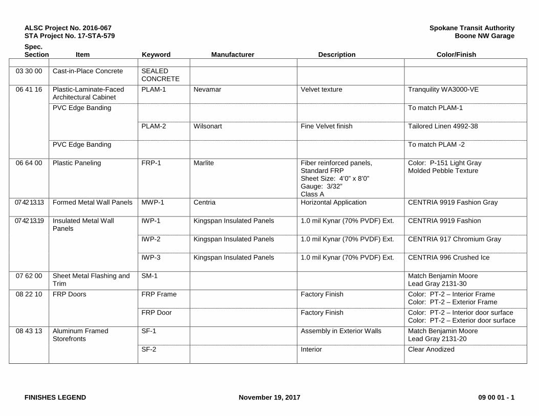
ALSC Project No. 2016-067 Spokane Transit Authority STA Project No. 17-STA-579 Boone NW Garage
Spec. Section Item Keyword Manufacturer Description Color/Finish
FINISHES LEGEND November 19, 2017 09 00 01 - 1
03 30 00 Cast-in-Place Concrete SEALED
CONCRETE
06 41 16 Plastic-Laminate-Faced Architectural Cabinet
PLAM-1 Nevamar Velvet texture Tranquility WA3000-VE
PVC Edge Banding To match PLAM-1
PLAM-2 Wilsonart Fine Velvet finish Tailored Linen 4992-38
PVC Edge Banding To match PLAM -2
06 64 00 Plastic Paneling FRP-1 Marlite Fiber reinforced panels, Standard FRP Sheet Size: 4’0” x 8’0” Gauge: 3/32” Class A
Color: P-151 Light Gray Molded Pebble Texture
07 42 13.13 Formed Metal Wall Panels MWP-1 Centria Horizontal Application CENTRIA 9919 Fashion Gray
07 42 13.19 Insulated Metal Wall Panels
IWP-1 Kingspan Insulated Panels 1.0 mil Kynar (70% PVDF) Ext. CENTRIA 9919 Fashion
IWP-2 Kingspan Insulated Panels 1.0 mil Kynar (70% PVDF) Ext. CENTRIA 917 Chromium Gray
IWP-3 Kingspan Insulated Panels 1.0 mil Kynar (70% PVDF) Ext. CENTRIA 996 Crushed Ice
07 62 00 Sheet Metal Flashing and Trim
SM-1 Match Benjamin Moore Lead Gray 2131-30
08 22 10 FRP Doors FRP Frame Factory Finish Color: PT-2 – Interior Frame Color: PT-2 – Exterior Frame
FRP Door Factory Finish Color: PT-2 – Interior door surface Color: PT-2 – Exterior door surface
08 43 13 Aluminum Framed Storefronts
SF-1 Assembly in Exterior Walls Match Benjamin Moore Lead Gray 2131-20
SF-2 Interior Clear Anodized

ALSC Project No. 2016-067 Spokane Transit Authority STA Project No. 17-STA-579 Boone NW Garage
Spec. Section Item Keyword Manufacturer Description Color/Finish
FINISHES LEGEND November 19, 2017 09 00 01 - 2
08 91 19 Fixed Louvers Assembly in Exterior Walls Match Benjamin Moore
Lead Gray 2131-30 09 51 13 Acoustical Panel Ceilings APC-1 Armstrong 1773 Dune, 24” x 48” x 5/8”;
Square lay-in White
09 64 13 Resilient Base and Accessories
RB-1 Johnsonite Rubber wall base Size: 4” High
Grey 48
Transition Strip TS-1 Johnsonite SSR-48-B 1/8” to floor
Grey 48
09 65 16 Resilient Sheet Flooring SV-1 Altro: Reliance 25 Self-cove base at Toilet Rooms Streetlight D2505
09 91 23 Painting P-1 Sherwin Williams Color: Silverpointe SW7653 Wall color
P-2 Sherwin Williams Color: Gray Matters SW7066 FRP Doors and Frames
P-3 Sherwin Williams Color: Online SW7072 Plywood wainscot finish
P-4 Sherwin Williams Color: Ceiling Bright White SW7007 Ceiling Color
P-5 Sherwin Williams Exterior steel O.H. door head and jamb covers
Color: Forsythia SW 6907 Interior Steel where indicated
10 26 00 Corner Guards CG-1 Koroseal Stainless Steel; surface mount. Height 8’-0”
Stainless Steel
13 34 19 Standing Seam Metal Roofing
Metal Building Systems Galvanized
END OF FINISHES LEGEND

Spokane Transit Authority Section 092216 Boone NW Garage Non-Structural Metal Framing
November 19, 2017 092216 - 1
SECTION 092216 - NON-STRUCTURAL METAL FRAMING
PART 1 - GENERAL
1.1 RELATED DOCUMENTS
A. Drawings and general provisions of the Contract, including General and Supplementary Conditions and Division 01 Specification Sections, apply to this Section.
1.2 SUMMARY
A. Section Includes:
1. Non-load-bearing steel framing systems for interior partitions. 2. Suspension systems for interior ceilings and soffits.
B. Related Requirements:
1. Section 054000 "Cold-Formed Metal Framing" for exterior and interior load-bearing and exterior non-load-bearing wall studs; floor joists; roof rafters and ceiling joists; and roof trusses.
1.3 ACTION SUBMITTALS
A. Product Data: For each type of product.
1.4 INFORMATIONAL SUBMITTALS
A. Product Certificates: For each type of code-compliance certification for studs and tracks.
B. Evaluation Reports: For post-installed anchors and power-actuated fasteners, from ICC-ES or other qualified testing agency acceptable to authorities having jurisdiction.
1.5 QUALITY ASSURANCE
A. Code-Compliance Certification of Studs and Tracks: Provide documentation that framing members are certified according to the product-certification program of the Certified Steel Stud Association the Steel Framing Industry Association or the Steel Stud Manufacturers Association.

Spokane Transit Authority Section 092216 Boone NW Garage Non-Structural Metal Framing
November 19, 2017 092216 - 2
PART 2 - PRODUCTS
2.1 PERFORMANCE REQUIREMENTS
A. Fire-Test-Response Characteristics: For fire-resistance-rated assemblies that incorporate non-load-bearing steel framing, provide materials and construction identical to those tested in assembly indicated, according to ASTM E 119 by an independent testing agency.
B. STC-Rated Assemblies: For STC-rated assemblies, provide materials and construction identical to those tested in assembly indicated on Drawings, according to ASTM E 90 and classified according to ASTM E 413 by an independent testing agency.
C. Horizontal Deflection: For wall assemblies, limited to 1/360 of the wall height based on horizontal loading of 5 lbf/sq. ft. (239 Pa).
2.2 FRAMING SYSTEMS
A. Framing Members, General: Comply with ASTM C 754 for conditions indicated.
1. Steel Sheet Components: Comply with ASTM C 645 requirements for metal unless otherwise indicated.
2. Protective Coating: ASTM A 653/A 653M, G60 (Z180), hot-dip galvanized unless otherwise indicated.
B. Studs and Tracks: ASTM C 645.[ Use either steel studs and tracks or embossed steel studs and tracks.]
1. Steel Studs and Tracks:
a. Manufacturers: Subject to compliance with requirements, provide products by one of the following:
1) CEMCO; California Expanded Metal Products Co. 2) Custom Stud. 3) Jaimes Industries. 4) MarinoWARE. 5) MBA Building Supplies. 6) MRI Steel Framing, LLC. 7) Phillips Manufacturing Co. 8) SCAFCO Steel Stud Company. 9) Steel Construction Systems. 10) Steel Network, Inc. (The). 11) Telling Industries.
b. Minimum Base-Metal Thickness: As required by performance requirements for horizontal deflection.
c. Depth: 6 inches (152 mm).

Spokane Transit Authority Section 092216 Boone NW Garage Non-Structural Metal Framing
November 19, 2017 092216 - 3
C. Slip-Type Head Joints: Where indicated, provide[ one of] the following:
1. Single Long-Leg Track System: ASTM C 645 top track with 2-inch- (51-mm-) deep flanges in thickness not less than indicated for studs, installed with studs friction fit into top track and with continuous bridging located within 12 inches (305 mm) of the top of studs to provide lateral bracing.
2. Double-Track System: ASTM C 645 top outer tracks, inside track with 2-inch- (51-mm-) deep flanges in thickness not less than indicated for studs and fastened to studs, and outer track sized to friction-fit over inner track.
3. Deflection Track: Steel sheet top track manufactured to prevent cracking of finishes applied to interior partition framing resulting from deflection of structure above; in thickness not less than indicated for studs and in width to accommodate depth of studs.
D. Flat Strap and Backing Plate: Steel sheet for blocking and bracing in length and width indicated.
1. Minimum Base-Metal Thickness: 0.0269 inch (0.683 mm).
E. Cold-Rolled Channel Bridging: Steel, 0.0538-inch (1.367-mm) minimum base-metal thickness, with minimum 1/2-inch- (13-mm-) wide flanges.
1. Depth: 1-1/2 inches (38 mm). 2. Clip Angle: Not less than 1-1/2 by 1-1/2 inches (38 by 38 mm), 0.068-inch- (1.72-mm-)
thick, galvanized steel.
F. Hat-Shaped, Rigid Furring Channels: ASTM C 645.
1. Minimum Base-Metal Thickness: 0.0179 inch (0.455 mm). 2. Depth: 1-1/2 inches (38 mm).
2.3 SUSPENSION SYSTEMS
A. Tie Wire: ASTM A 641/A 641M, Class 1 zinc coating, soft temper, 0.062-inch- (1.59-mm-) diameter wire, or double strand of 0.048-inch- (1.21-mm-) diameter wire.
B. Hanger Attachments to Concrete:
1. Post-Installed Anchors: Fastener systems with an evaluation report acceptable to authorities having jurisdiction.
a. Uses: Securing hangers to structure. b. Type: Torque-controlled, expansion anchor or adhesive anchor. c. Material for Interior Locations: Carbon-steel components zinc-plated to comply
with ASTM B 633 or ASTM F 1941 (ASTM F 1941M), Class Fe/Zn 5, unless otherwise indicated.
d. Material for Exterior or Interior Locations and Where Stainless Steel Is Indicated: stainless-steel bolts, ASTM F 593 (ASTM F 738M), and nuts, ASTM F 594 (ASTM F 836M).
2. Power-Actuated Anchors: Fastener systems with an evaluation report acceptable to authorities having jurisdiction, based on ICC-ES AC70.

Spokane Transit Authority Section 092216 Boone NW Garage Non-Structural Metal Framing
November 19, 2017 092216 - 4
C. Wire Hangers: ASTM A 641/A 641M, Class 1 zinc coating, soft temper, 0.16 inch (4.12 mm) in diameter.
D. Flat Hangers: Steel sheet, 1 by 3/16 inch (25 by 5 mm) by length indicated.
E. Carrying Channels (Main Runners): Cold-rolled, commercial-steel sheet with a base-metal thickness of 0.0538 inch (1.367 mm) and minimum 1/2-inch- (13-mm-) wide flanges.
1. Depth: 1-1/2 inches (38 mm).
F. Furring Channels (Furring Members):
1. Cold-Rolled Channels: 0.0538-inch (1.367-mm) uncoated-steel thickness, with minimum 1/2-inch- (13-mm-) wide flanges, 3/4 inch (19 mm) deep.
2. Steel Studs and Tracks: ASTM C 645.
a. Minimum Base-Metal Thickness: 0.0179 inch (0.455 mm). b. Depth: 2-1/2 inches (64 mm).
3. Hat-Shaped, Rigid Furring Channels: ASTM C 645, 7/8 inch (22 mm) deep.
a. Minimum Base-Metal Thickness: As indicated on Drawings 0.0179 inch (0.455 mm).
4. Resilient Furring Channels: 1/2-inch- (13-mm-) deep members designed to reduce sound transmission.
a. Configuration: Asymmetrical or hat shaped.
2.4 AUXILIARY MATERIALS
A. General: Provide auxiliary materials that comply with referenced installation standards.
1. Fasteners for Steel Framing: Of type, material, size, corrosion resistance, holding power, and other properties required to fasten steel members to substrates.
B. Isolation Strip at Exterior Walls: Provide one of the following:
1. Asphalt-Saturated Organic Felt: ASTM D 226/D 226M, Type I (No. 15 asphalt felt), nonperforated.
2. Foam Gasket: Adhesive-backed, closed-cell vinyl foam strips that allow fastener penetration without foam displacement, 1/8 inch (3.2 mm) thick, in width to suit steel stud size.

Spokane Transit Authority Section 092216 Boone NW Garage Non-Structural Metal Framing
November 19, 2017 092216 - 5
PART 3 - EXECUTION
3.1 EXAMINATION
A. Examine areas and substrates, with Installer present, and including welded hollow-metal frames, cast-in anchors, and structural framing, for compliance with requirements and other conditions affecting performance of the Work.
B. Proceed with installation only after unsatisfactory conditions have been corrected.
3.2 PREPARATION
A. Suspended Assemblies: Coordinate installation of suspension systems with installation of overhead structure to ensure that inserts and other provisions for anchorages to building structure have been installed to receive hangers at spacing required to support the Work and that hangers will develop their full strength.
1. Furnish concrete inserts and other devices indicated to other trades for installation in advance of time needed for coordination and construction.
B. Coordination with Sprayed Fire-Resistive Materials:
1. Before sprayed fire-resistive materials are applied, attach offset anchor plates or ceiling tracks to surfaces indicated to receive sprayed fire-resistive materials. Where offset anchor plates are required, provide continuous plates fastened to building structure not more than 24 inches (610 mm) o.c.
2. After sprayed fire-resistive materials are applied, remove them only to extent necessary for installation of non-load-bearing steel framing. Do not reduce thickness of fire-resistive materials below that are required for fire-resistance ratings indicated. Protect adjacent fire-resistive materials from damage.
3.3 INSTALLATION, GENERAL
A. Installation Standard: ASTM C 754.
1. Gypsum Plaster Assemblies: Also comply with requirements in ASTM C 841 that apply to framing installation.
2. Portland Cement Plaster Assemblies: Also comply with requirements in ASTM C 1063 that apply to framing installation.
3. Gypsum Veneer Plaster Assemblies: Also comply with requirements in ASTM C 844 that apply to framing installation.
4. Gypsum Board Assemblies: Also comply with requirements in ASTM C 840 that apply to framing installation.
B. Install framing and accessories plumb, square, and true to line, with connections securely fastened.
C. Install supplementary framing, and blocking to support fixtures, equipment services, heavy trim, grab bars, toilet accessories, furnishings, or similar construction.

Spokane Transit Authority Section 092216 Boone NW Garage Non-Structural Metal Framing
November 19, 2017 092216 - 6
D. Install bracing at terminations in assemblies.
E. Do not bridge building control and expansion joints with non-load-bearing steel framing members. Frame both sides of joints independently.
3.4 INSTALLING FRAMED ASSEMBLIES
A. Install framing system components according to spacings indicated, but not greater than spacings required by referenced installation standards for assembly types.
1. Single-Layer Application: 16 inches (406 mm) o.c. unless otherwise indicated. 2. Multilayer Application: 16 inches (406 mm) o.c. unless otherwise indicated.
B. Where studs are installed directly against exterior masonry walls or dissimilar metals at exterior walls, install isolation strip between studs and exterior wall.
C. Install studs so flanges within framing system point in same direction.
D. Install tracks at floors and overhead supports. Extend framing full height to structural supports or substrates above suspended ceilings except where partitions are indicated to terminate at suspended ceilings. Continue framing around ducts that penetrate partitions above ceiling.
1. Slip-Type Head Joints: Where framing extends to overhead structural supports, install to produce joints at tops of framing systems that prevent axial loading of finished assemblies.
2. Door Openings: Screw vertical studs at jambs to jamb anchor clips on door frames; install track section (for cripple studs) at head and secure to jamb studs.
a. Install two studs at each jamb unless otherwise indicated. b. Install cripple studs at head adjacent to each jamb stud, with a minimum 1/2-inch
(13-mm) clearance from jamb stud to allow for installation of control joint in finished assembly.
c. Extend jamb studs through suspended ceilings and attach to underside of overhead structure.
3. Other Framed Openings: Frame openings other than door openings the same as required for door openings unless otherwise indicated. Install framing below sills of openings to match framing required above door heads.
4. Fire-Resistance-Rated Partitions: Install framing to comply with fire-resistance-rated assembly indicated and support closures and to make partitions continuous from floor to underside of solid structure.
a. Firestop Track: Where indicated, install to maintain continuity of fire-resistance-rated assembly indicated.
5. Sound-Rated Partitions: Install framing to comply with sound-rated assembly indicated.
E. Direct Furring:
1. Screw to wood framing.

Spokane Transit Authority Section 092216 Boone NW Garage Non-Structural Metal Framing
November 19, 2017 092216 - 7
2. Attach to concrete or masonry with stub nails, screws designed for masonry attachment, or powder-driven fasteners spaced 24 inches (610 mm) o.c.
F. Installation Tolerance: Install each framing member so fastening surfaces vary not more than 1/8 inch (3 mm) from the plane formed by faces of adjacent framing.
3.5 INSTALLING CEILING SUSPENSION SYSTEMS
A. Install suspension system components according to spacings indicated, but not greater than spacings required by referenced installation standards for assembly types.
1. Hangers: 48 inches (1219 mm) o.c. 2. Carrying Channels (Main Runners): 48 inches (1219 mm) o.c. 3. Furring Channels (Furring Members): 24 inches (610 mm) o.c.
B. Isolate suspension systems from building structure where they abut or are penetrated by building structure to prevent transfer of loading imposed by structural movement.
C. Suspend hangers from building structure as follows:
1. Install hangers plumb and free from contact with insulation or other objects within ceiling plenum that are not part of supporting structural or suspension system.
a. Splay hangers only where required to miss obstructions and offset resulting horizontal forces by bracing, countersplaying, or other equally effective means.
2. Where width of ducts and other construction within ceiling plenum produces hanger spacings that interfere with locations of hangers required to support standard suspension system members, install supplemental suspension members and hangers in the form of trapezes or equivalent devices.
a. Size supplemental suspension members and hangers to support ceiling loads within performance limits established by referenced installation standards.
3. Wire Hangers: Secure by looping and wire tying, either directly to structures or to inserts, eye screws, or other devices and fasteners that are secure and appropriate for substrate, and in a manner that will not cause hangers to deteriorate or otherwise fail.
4. Flat Hangers: Secure to structure, including intermediate framing members, by attaching to inserts, eye screws, or other devices and fasteners that are secure and appropriate for structure and hanger, and in a manner that will not cause hangers to deteriorate or otherwise fail.
5. Do not attach hangers to steel roof deck. 6. Do not attach hangers to permanent metal forms. Furnish cast-in-place hanger inserts that
extend through forms. 7. Do not attach hangers to rolled-in hanger tabs of composite steel floor deck. 8. Do not connect or suspend steel framing from ducts, pipes, or conduit.
D. Fire-Resistance-Rated Assemblies: Wire tie furring channels to supports.
E. Seismic Bracing: Sway-brace suspension systems: Reference detail in the drawings.

Spokane Transit Authority Section 092216 Boone NW Garage Non-Structural Metal Framing
November 19, 2017 092216 - 8
F. Grid Suspension Systems: Attach perimeter wall track or angle where grid suspension systems meet vertical surfaces. Mechanically join main beam and cross-furring members to each other and butt-cut to fit into wall track.
G. Installation Tolerances: Install suspension systems that are level to within 1/8 inch in 12 feet (3 mm in 3.6 m) measured lengthwise on each member that will receive finishes and transversely between parallel members that will receive finishes.
END OF SECTION 092216

Spokane Transit Authority Section 092900
Boone NW Garage Gypsum Board
November 19, 2017 092900 - 1
SECTION 092900 - GYPSUM BOARD
PART 1 - GENERAL
1.1 RELATED DOCUMENTS
A. Drawings and general provisions of the Contract, including General and Supplementary
Conditions and Division 01 Specification Sections, apply to this Section.
1.2 SUMMARY
A. Section Includes:
1. Interior gypsum board.
B. Related Requirements:
1. Section 092216 "Non-Structural Metal Framing" for non-structural steel framing and
suspension systems that support gypsum board panels.
1.3 ACTION SUBMITTALS
A. Product Data: For each type of product.
1.4 DELIVERY, STORAGE AND HANDLING
A. Store materials inside under cover and keep them dry and protected against weather,
condensation, direct sunlight, construction traffic, and other potential causes of damage. Stack
panels flat and supported on risers on a flat platform to prevent sagging.
1.5 FIELD CONDITIONS
A. Environmental Limitations: Comply with ASTM C 840 requirements or gypsum board
manufacturer's written instructions, whichever are more stringent.
B. Do not install paper-faced gypsum panels until installation areas are enclosed and conditioned.
C. Do not install panels that are wet, moisture damaged, and mold damaged.
1. Indications that panels are wet or moisture damaged include, but are not limited to,
discoloration, sagging, or irregular shape.
2. Indications that panels are mold damaged include, but are not limited to, fuzzy or
splotchy surface contamination and discoloration.

Spokane Transit Authority Section 092900
Boone NW Garage Gypsum Board
November 19, 2017 092900 - 2
PART 2 - PRODUCTS
2.1 PERFORMANCE REQUIREMENTS
A. Fire-Resistance-Rated Assemblies: For fire-resistance-rated assemblies, provide materials and
construction identical to those tested in assembly indicated according to ASTM E 119 by an
independent testing agency.
2.2 GYPSUM BOARD, GENERAL
A. Size: Provide maximum lengths and widths available that will minimize joints in each area and
that correspond with support system indicated.
2.3 INTERIOR GYPSUM BOARD
A. Gypsum Board, Type X: ASTM C 1396/C 1396M.
1. Manufacturers: Subject to compliance with requirements, provide products by one of the
following:
a. American Gypsum.
b. CertainTeed Corporation.
c. Continental Building Products, LLC.
d. Georgia-Pacific Gypsum LLC.
e. National Gypsum Company.
f. PABCO Gypsum.
g. Temple-Inland Building Products by Georgia-Pacific.
h. USG Corporation.
2. Thickness: 15.9 mm (5/8 inch).
3. Long Edges: Tapered for prefilling.
2.4 TRIM ACCESSORIES
A. Interior Trim: ASTM C 1047.
1. Material: Galvanized or aluminum-coated steel sheet or rolled zinc.
2. Shapes:
a. Cornerbead.
b. Bullnose bead.
c. LC-Bead: J-shaped; exposed long flange receives joint compound.
d. L-Bead: L-shaped; exposed long flange receives joint compound.
e. U-Bead: J-shaped; exposed short flange does not receive joint compound.
f. Expansion (control) joint.

Spokane Transit Authority Section 092900
Boone NW Garage Gypsum Board
November 19, 2017 092900 - 3
2.5 JOINT TREATMENT MATERIALS
A. General: Comply with ASTM C 475/C 475M.
B. Joint Tape:
1. Interior Gypsum Board: Paper.
C. Joint Compound for Interior Gypsum Board: For each coat, use formulation that is compatible
with other compounds applied on previous or for successive coats.
1. Prefilling: At open joints, rounded or beveled panel edges, and damaged surface areas,
use setting-type taping compound.
2. Embedding and First Coat: For embedding tape and first coat on joints, fasteners, and
trim flanges, use setting-type taping compound.
a. Use setting-type compound for installing paper-faced metal trim accessories.
3. Fill Coat: For second coat, use setting-type, sandable topping or drying-type, all-purpose
compound.
4. Finish Coat: For third coat, use setting-type, sandable topping or drying-type, all-purpose
compound.
2.6 AUXILIARY MATERIALS
A. General: Provide auxiliary materials that comply with referenced installation standards and
manufacturer's written instructions.
B. Steel Drill Screws: ASTM C 1002 unless otherwise indicated.
1. Use screws complying with ASTM C 954 for fastening panels to steel members from
0.84 to 2.84 mm (0.033 to 0.112 inch) thick.
2. For fastening cementitious backer units, use screws of type and size recommended by
panel manufacturer.
C. Acoustical Sealant: Manufacturer's standard nonsag, paintable, nonstaining latex sealant
complying with ASTM C 834. Product effectively reduces airborne sound transmission through
perimeter joints and openings in building construction as demonstrated by testing representative
assemblies according to ASTM E 90.
D. Thermal Insulation: As specified in Section 072100 "Thermal Insulation."
E. Vapor Retarder: As specified in Section 072600 "Vapor Retarders."

Spokane Transit Authority Section 092900
Boone NW Garage Gypsum Board
November 19, 2017 092900 - 4
PART 3 - EXECUTION
3.1 EXAMINATION
A. Examine areas and substrates including welded hollow-metal frames and support framing, with
Installer present, for compliance with requirements and other conditions affecting performance
of the Work.
B. Examine panels before installation. Reject panels that are wet, moisture damaged, and mold
damaged.
C. Proceed with installation only after unsatisfactory conditions have been corrected.
3.2 APPLYING AND FINISHING PANELS, GENERAL
A. Comply with ASTM C 840.
B. Install ceiling panels across framing to minimize the number of abutting end joints and to avoid
abutting end joints in central area of each ceiling. Stagger abutting end joints of adjacent panels
not less than one framing member.
C. Install panels with face side out. Butt panels together for a light contact at edges and ends with
not more than 1.5 mm (1/16 inch) of open space between panels. Do not force into place.
D. Locate edge and end joints over supports, except in ceiling applications where intermediate
supports or gypsum board back-blocking is provided behind end joints. Do not place tapered
edges against cut edges or ends. Stagger vertical joints on opposite sides of partitions. Do not
make joints other than control joints at corners of framed openings.
E. Form control and expansion joints with space between edges of adjoining gypsum panels.
F. Cover both faces of support framing with gypsum panels in concealed spaces (above ceilings,
etc.), except in chases braced internally.
1. Unless concealed application is indicated or required for sound, fire, air, or smoke
ratings, coverage may be accomplished with scraps of not less than 0.7 sq. m (8 sq. ft.) in
area.
2. Fit gypsum panels around ducts, pipes, and conduits.
3. Where partitions intersect structural members projecting below underside of floor/roof
slabs and decks, cut gypsum panels to fit profile formed by structural members; allow
6.4- to 9.5-mm- (1/4- to 3/8-inch-) wide joints to install sealant.
G. Isolate perimeter of gypsum board applied to non-load-bearing partitions at structural
abutments. Provide 6.4- to 12.7-mm- (1/4- to 1/2-inch-) wide spaces at these locations and trim
edges with edge trim where edges of panels are exposed. Seal joints between edges and abutting
structural surfaces with acoustical sealant.
H. Attachment to Steel Framing: Attach panels so leading edge or end of each panel is attached to
open (unsupported) edges of stud flanges first.
Spokane Transit Authority Section 092900
Boone NW Garage Gypsum Board
November 19, 2017 092900 - 5
3.3 APPLYING INTERIOR GYPSUM BOARD
A. Install interior gypsum board in the following locations:
1. Type X: Vertical surfaces unless otherwise indicated.
2. Ceiling Type: Type X.
B. Single-Layer Application:
1. On ceilings, apply gypsum panels before wall/partition board application to greatest
extent possible and at right angles to framing unless otherwise indicated.
2. On partitions/walls, apply gypsum panels horizontally (perpendicular to framing) unless
otherwise indicated or required by fire-resistance-rated assembly, and minimize end
joints.
a. Stagger abutting end joints not less than one framing member in alternate courses
of panels.
b. At stairwells and other high walls, install panels horizontally unless otherwise
indicated or required by fire-resistance-rated assembly.
3. Fastening Methods: Apply gypsum panels to supports with steel drill screws.
3.4 INSTALLING TRIM ACCESSORIES
A. General: For trim with back flanges intended for fasteners, attach to framing with same
fasteners used for panels. Otherwise, attach trim according to manufacturer's written
instructions.
B. Control Joints: Install control joints at locations indicated on Drawings and according to
ASTM C 840 and in specific locations approved by Architect for visual effect.
C. Interior Trim: Install in the following locations:
1. Cornerbead: Use at outside corners.
2. L-Bead: Use where indicated.
3. U-Bead: Use at exposed panel edges.
3.5 FINISHING GYPSUM BOARD
A. General: Treat gypsum board joints, interior angles, edge trim, control joints, penetrations,
fastener heads, surface defects, and elsewhere as required to prepare gypsum board surfaces for
decoration. Promptly remove residual joint compound from adjacent surfaces.
B. Prefill open joints, rounded or beveled edges, and damaged surface areas.
C. Apply joint tape over gypsum board joints, except for trim products specifically indicated as not
intended to receive tape.
D. Gypsum Board Finish Levels: Finish panels to levels indicated below and according to
ASTM C 840:
1. Level 1: Ceiling plenum areas, concealed areas, and where indicated.
Spokane Transit Authority Section 092900
Boone NW Garage Gypsum Board
November 19, 2017 092900 - 6
2. Level 4: At panel surfaces that will be exposed to view unless otherwise indicated.
a. Primer and its application to surfaces are specified in Section 099123 "Interior
Painting."
3.6 PROTECTION
A. Protect adjacent surfaces from drywall compound and promptly remove from floors and other
non-drywall surfaces. Repair surfaces stained, marred, or otherwise damaged during drywall
application.
B. Protect installed products from damage from weather, condensation, direct sunlight,
construction, and other causes during remainder of the construction period.
C. Remove and replace panels that are wet, moisture damaged, and mold damaged.
1. Indications that panels are wet or moisture damaged include, but are not limited to,
discoloration, sagging, or irregular shape.
2. Indications that panels are mold damaged include, but are not limited to, fuzzy or
splotchy surface contamination and discoloration.
END OF SECTION 092900
Spokane Transit Authority Section 095113
Boone NW Garage Acoustical Panel Ceilings
November 19, 2017 095113 - 1
SECTION 095113 - ACOUSTICAL PANEL CEILINGS
PART 1 - GENERAL
1.1 RELATED DOCUMENTS
A. Drawings and general provisions of the Contract, including General and Supplementary
Conditions and Division 01 Specification Sections, apply to this Section.
1.2 SUMMARY
A. Section includes acoustical panels and exposed suspension systems for interior ceilings.
1.3 ACTION SUBMITTALS
A. Product Data: For each type of product.
B. Samples: For each exposed product and for each color and texture specified, 6 inches (150 mm)
in size.
C. Samples for Initial Selection: For components with factory-applied finishes.
D. Samples for Verification: For each component indicated and for each exposed finish required,
prepared on Samples of sizes indicated below:
1. Acoustical Panels: Set of 6-inch- (150-mm-) square Samples of each type, color, pattern,
and texture.
2. Exposed Suspension-System Members, Moldings, and Trim: Set of 6-inch- (150-mm-)
long Samples of each type, finish, and color.
1.4 INFORMATIONAL SUBMITTALS
A. Product Test Reports: For each acoustical panel ceiling, for tests performed by a qualified
testing agency.
B. Evaluation Reports: For each acoustical panel ceiling suspension system and anchor and
fastener type, from ICC-ES.
C. Field quality-control reports.
1.5 CLOSEOUT SUBMITTALS
A. Maintenance Data: For finishes to include in maintenance manuals.

Spokane Transit Authority Section 095113
Boone NW Garage Acoustical Panel Ceilings
November 19, 2017 095113 - 2
1.6 MAINTENANCE MATERIAL SUBMITTALS
A. Furnish extra materials, from the same product run, that match products installed and that are
packaged with protective covering for storage and identified with labels describing contents.
1. Acoustical Ceiling Units: Full-size panels equal to 10 percent of quantity installed.
2. Suspension-System Components: Quantity of each exposed component equal to 10
percent of quantity installed.
1.7 DELIVERY, STORAGE, AND HANDLING
A. Deliver acoustical panels, suspension-system components, and accessories to Project site and
store them in a fully enclosed, conditioned space where they will be protected against damage
from moisture, humidity, temperature extremes, direct sunlight, surface contamination, and
other causes.
B. Before installing acoustical panels, permit them to reach room temperature and a stabilized
moisture content.
1.8 FIELD CONDITIONS
A. Environmental Limitations: Do not install acoustical panel ceilings until spaces are enclosed
and weathertight, wet-work in spaces is complete and dry, work above ceilings is complete, and
ambient temperature and humidity conditions are maintained at the levels indicated for Project
when occupied for its intended use.
1. Pressurized Plenums: Operate ventilation system for not less than 48 hours before
beginning acoustical panel ceiling installation.
PART 2 - PRODUCTS
2.1 MANUFACTURERS
A. Source Limitations: Obtain each type of acoustical ceiling panel and its supporting suspension
system from single source from single manufacturer.
2.2 PERFORMANCE REQUIREMENTS
A. Seismic Performance: Suspended ceilings shall withstand the effects of earthquake motions
determined according to ASCE/SEI 7.
B. Surface-Burning Characteristics: Comply with ASTM E 84; testing by a qualified testing
agency. Identify products with appropriate markings of applicable testing agency.
1. Flame-Spread Index: Class A according to ASTM E 1264.
2. Smoke-Developed Index: 50 or less.

Spokane Transit Authority Section 095113
Boone NW Garage Acoustical Panel Ceilings
November 19, 2017 095113 - 3
2.3 ACOUSTICAL PANELS
A. Manufacturers: Subject to compliance with requirements, provide products by one of the
following:
1. American Gypsum.
2. Armstrong World Industries, Inc.
3. CertainTeed Corporation.
4. Chicago Metallic Corporation.
5. Rockfon (Roxul Inc.).
6. Tectum Inc.
7. USG Corporation.
B. Acoustical Panel Standard: Provide manufacturer's standard panels according to ASTM E 1264
and designated by type, form, pattern, acoustical rating, and light reflectance unless otherwise
indicated.
C. Classification: Provide panels as follows:
1. Type and Form: Type III, mineral base with painted finish; Form 2, water felted.
2. Pattern: as indicated by manufacturer's designation. Refer to Finishes Legend
D. Color: White.
E. Light Reflectance (LR): Not less than 0.85.
F. Ceiling Attenuation Class (CAC): Not less than 40.
G. Noise Reduction Coefficient (NRC): Not less than 0.70.
H. Edge/Joint Detail: Square.
I. Thickness: 3/4 inch (19 mm).
J. Modular Size: 24 by 48 inches (610 by 1220 mm).
K. Antimicrobial Treatment: Manufacturer's standard broad spectrum, antimicrobial formulation
that inhibits fungus, mold, mildew, and gram-positive and gram-negative bacteria and showing
no mold, mildew, or bacterial growth when tested according to ASTM D 3273, ASTM D 3274,
or ASTM G 21 and evaluated according to ASTM D 3274 or ASTM G 21.
2.4 METAL SUSPENSION SYSTEM
A. Manufacturers: Subject to compliance with requirements, provide products by one of the
following:
1. Armstrong World Industries, Inc.
2. CertainTeed Corporation.
3. Chicago Metallic Corporation.
4. USG Corporation.

Spokane Transit Authority Section 095113
Boone NW Garage Acoustical Panel Ceilings
November 19, 2017 095113 - 4
B. Metal Suspension-System Standard: Provide manufacturer's standard, direct-hung, metal
suspension system and accessories according to ASTM C 635/C 635M and designated by type,
structural classification, and finish indicated.
1. High-Humidity Finish: Provide coating tested and classified for "severe environment
performance" according to ASTM C 635/C 635M.
C. Wide-Face, Capped, Double-Web, Steel Suspension System: Main and cross runners roll
formed from cold-rolled steel sheet; prepainted, electrolytically zinc coated, or hot-dip
galvanized, G30 (Z90) coating designation; with prefinished 15/16-inch- (24-mm-) wide metal
caps on flanges.
1. Structural Classification: Intermediate-duty system.
2. End Condition of Cross Runners: Override (stepped) or butt-edge type.
3. Face Design: Flat, flush.
4. Cap Material: Aluminum.
5. Cap Finish: Painted white.
2.5 ACCESSORIES
A. Attachment Devices: Size for five times the design load indicated in ASTM C 635/C 635M,
Table 1, "Direct Hung," unless otherwise indicated. Comply with seismic design requirements.
B. Wire Hangers, Braces, and Ties: Provide wires as follows:
1. Stainless-Steel Wire: ASTM A 580/A 580M, Type 304, nonmagnetic.
2. Nickel-Copper-Alloy Wire: ASTM B 164, nickel-copper-alloy UNS No. N04400.
3. Size: Wire diameter sufficient for its stress at three times hanger design load
(ASTM C 635/C 635M, Table 1, "Direct Hung") will be less than yield stress of wire, but
not less than 0.106-inch- (2.69-mm-) diameter wire.
C. Hanger Rods: Mild steel, zinc coated or protected with rust-inhibitive paint.
D. Flat Hangers: Mild steel, zinc coated or protected with rust-inhibitive paint.
E. Angle Hangers: Angles with legs not less than 7/8 inch (22 mm) wide; formed with 0.04-inch-
(1-mm-) thick, galvanized-steel sheet complying with ASTM A 653/A 653M, G90 (Z275)
coating designation; with bolted connections and 5/16-inch- (8-mm-) diameter bolts.
F. Seismic Clips: Manufacturer's standard seismic clips designed to secure acoustical panels in
place during a seismic event.
G. Seismic Stabilizer Bars: Manufacturer's standard perimeter stabilizers designed to accommodate
seismic forces.
H. Seismic Struts: Manufacturer's standard compression struts designed to accommodate seismic
forces.

Spokane Transit Authority Section 095113
Boone NW Garage Acoustical Panel Ceilings
November 19, 2017 095113 - 5
2.6 ACOUSTICAL SEALANT
A. Acoustical Sealant: As specified in Section 079219 "Acoustical Joint Sealants."
PART 3 - EXECUTION
3.1 EXAMINATION
A. Examine substrates, areas, and conditions, including structural framing to which acoustical
panel ceilings attach or abut, with Installer present, for compliance with requirements specified
in this and other Sections that affect ceiling installation and anchorage and with requirements
for installation tolerances and other conditions affecting performance of acoustical panel
ceilings.
B. Examine acoustical panels before installation. Reject acoustical panels that are wet, moisture
damaged, or mold damaged.
C. Proceed with installation only after unsatisfactory conditions have been corrected.
3.2 PREPARATION
A. Measure each ceiling area and establish layout of acoustical panels to balance border widths at
opposite edges of each ceiling. Avoid using less-than-half-width panels at borders unless
otherwise indicated, and comply with layout shown on reflected ceiling plans.
B. Layout openings for penetrations centered on the penetrating items.
3.3 INSTALLATION
A. Install acoustical panel ceilings according to ASTM C 636/C 636M and manufacturer's written
instructions.
B. Suspend ceiling hangers from building's structural members and as follows:
1. Install hangers plumb and free from contact with insulation or other objects within ceiling
plenum that are not part of supporting structure or of ceiling suspension system.
2. Splay hangers only where required[ and, if permitted with fire-resistance-rated ceilings,]
to miss obstructions; offset resulting horizontal forces by bracing, countersplaying, or
other equally effective means.
3. Where width of ducts and other construction within ceiling plenum produces hanger
spacings that interfere with location of hangers at spacings required to support standard
suspension-system members, install supplemental suspension members and hangers in
form of trapezes or equivalent devices.
4. Secure wire hangers to ceiling-suspension members and to supports above with a
minimum of three tight turns. Connect hangers directly to structure or to inserts, eye
screws, or other devices that are secure and appropriate for substrate and that will not
deteriorate or otherwise fail due to age, corrosion, or elevated temperatures.

Spokane Transit Authority Section 095113
Boone NW Garage Acoustical Panel Ceilings
November 19, 2017 095113 - 6
5. Secure flat, angle, channel, and rod hangers to structure, including intermediate framing
members, by attaching to inserts, eye screws, or other devices that are secure and
appropriate for both the structure to which hangers are attached and the type of hanger
involved. Install hangers in a manner that will not cause them to deteriorate or fail due to
age, corrosion, or elevated temperatures.
6. Do not support ceilings directly from permanent metal forms or floor deck. Fasten
hangers to cast-in-place hanger inserts, postinstalled mechanical or adhesive anchors, or
power-actuated fasteners that extend through forms into concrete.
7. When steel framing does not permit installation of hanger wires at spacing required,
install carrying channels or other supplemental support for attachment of hanger wires.
8. Do not attach hangers to steel deck tabs.
9. Do not attach hangers to steel roof deck. Attach hangers to structural members.
10. Space hangers not more than 48 inches (1200 mm) o.c. along each member supported
directly from hangers unless otherwise indicated; provide hangers not more than 8 inches
(200 mm) from ends of each member.
11. Size supplemental suspension members and hangers to support ceiling loads within
performance limits established by referenced standards.
C. Secure bracing wires to ceiling suspension members and to supports with a minimum of four
tight turns. Suspend bracing from building's structural members as required for hangers, without
attaching to permanent metal forms, steel deck, or steel deck tabs. Fasten bracing wires into
concrete with cast-in-place or postinstalled anchors.
D. Install edge moldings and trim of type indicated at perimeter of acoustical ceiling area and
where necessary to conceal edges of acoustical panels.
1. Apply acoustical sealant in a continuous ribbon concealed on back of vertical legs of
moldings before they are installed.
2. Screw attach moldings to substrate at intervals not more than 16 inches (400 mm) o.c.
and not more than 3 inches (75 mm) from ends. Miter corners accurately and connect
securely.
3. Do not use exposed fasteners, including pop rivets, on moldings and trim.
E. Install suspension-system runners so they are square and securely interlocked with one another.
Remove and replace dented, bent, or kinked members.
F. Install acoustical panels with undamaged edges and fit accurately into suspension-system
runners and edge moldings. Scribe and cut panels at borders and penetrations to provide precise
fit.
1. Arrange directionally patterned acoustical panels as follows:
a. As indicated on reflected ceiling plans.
2. For square-edged panels, install panels with edges fully hidden from view by flanges of
suspension-system runners and moldings.
3. For reveal-edged panels on suspension-system runners, install panels with bottom of
reveal in firm contact with top surface of runner flanges.
4. For reveal-edged panels on suspension-system members with box-shaped flanges, install
panels with reveal surfaces in firm contact with suspension-system surfaces and panel
faces flush with bottom face of runners.

Spokane Transit Authority Section 095113
Boone NW Garage Acoustical Panel Ceilings
November 19, 2017 095113 - 7
5. Paint cut edges of panel remaining exposed after installation; match color of exposed
panel surfaces using coating recommended in writing for this purpose by acoustical panel
manufacturer.
6. Protect lighting fixtures and air ducts according to requirements indicated for fire-
resistance-rated assembly.
3.4 ERECTION TOLERANCES
A. Suspended Ceilings: Install main and cross runners level to a tolerance of [1/8 inch in 12 feet (3
mm in 3.6 m)], non-cumulative.
B. Moldings and Trim: Install moldings and trim to substrate and level with ceiling suspension
system to a tolerance of [1/8 inch in 12 feet (3 mm in 3.6 m)], non-cumulative.
3.5 CLEANING
A. Clean exposed surfaces of acoustical panel ceilings, including trim, edge moldings, and
suspension-system members. Comply with manufacturer's written instructions for cleaning and
touchup of minor finish damage.
B. Remove and replace ceiling components that cannot be successfully cleaned and repaired to
permanently eliminate evidence of damage.
END OF SECTION 095113

Spokane Transit Authority Section 095113
Boone NW Garage Acoustical Panel Ceilings
November 19, 2017 095113 - 8
THIS PAGE INTENTIONALLY LEFT BLANK

Spokane Transit Authority Section 096513 Boone NW Garage Resilient Base and Accessories
November 19, 2017 096513 - 1
SECTION 096513 - RESILIENT BASE AND ACCESSORIES
PART 1 - GENERAL
1.1 RELATED DOCUMENTS
A. Drawings and general provisions of the Contract, including General and Supplementary Conditions and Division 01 Specification Sections, apply to this Section.
1.2 SUMMARY
A. Section Includes:
1. Thermoset-rubber base. 2. Rubber molding accessories.
1.3 ACTION SUBMITTALS
A. Product Data: For each type of product.
B. Samples: For each exposed product and for each color and texture specified, not less than 12 inches (300 mm) long.
C. Samples for Initial Selection: For each type of product indicated.
D. Samples for Verification: For each type of product indicated and for each color, texture, and pattern required in manufacturer's standard-size Samples, but not less than 12 inches (300 mm) long.
E. Product Schedule: For resilient base and accessory products. Use same designations indicated on Drawings.
1.4 MAINTENANCE MATERIAL SUBMITTALS
A. Furnish extra materials, from the same product run, that match products installed and that are packaged with protective covering for storage and identified with labels describing contents.
1. Furnish not less than 10 linear feet (3 linear m) of each type, color, pattern, and size of resilient product installed.
1.5 DELIVERY, STORAGE, AND HANDLING
A. Store resilient products and installation materials in dry spaces protected from the weather, with ambient temperatures maintained within range recommended by manufacturer, but not less than 50 deg F (10 deg C) or more than 90 deg F (32 deg C).

Spokane Transit Authority Section 096513 Boone NW Garage Resilient Base and Accessories
November 19, 2017 096513 - 2
1.6 FIELD CONDITIONS
A. Maintain ambient temperatures within range recommended by manufacturer, but not less than 45 deg F or more than 95 deg F (35 deg C), in spaces to receive resilient products during the following periods:
1. 48 hours before installation. 2. During installation. 3. 48 hours after installation.
B. After installation and until Substantial Completion, maintain ambient temperatures within range recommended by manufacturer, but not less than 45 deg F or more than 95 deg F (35 deg C).
C. Install resilient products after other finishing operations, including painting, have been completed.
PART 2 - PRODUCTS
2.1 THERMOSET-RUBBER BASE
A. Manufacturers: Subject to compliance with requirements, provide products by one of the following:
1. Burke Mercer Flooring Products; a division of Burke Industries Inc. 2. Flexco. 3. Johnsonite; a Tarkett company. 4. Roppe Corporation, USA.
B. Product Standard: ASTM F 1861, Type TS (rubber, vulcanized thermoset), Group I (solid, homogeneous).
1. Style and Location:
a. Style B, Cove: .
C. Thickness: 0.125 inch (3.2 mm).
D. Height: 4 inches (102 mm).
E. Lengths: Coils in manufacturer's standard length.
F. Outside Corners: Job formed.
G. Inside Corners: Job formed.
H. Colors: As indicated by manufacturer's designations.

Spokane Transit Authority Section 096513 Boone NW Garage Resilient Base and Accessories
November 19, 2017 096513 - 3
2.2 RUBBER MOLDING ACCESSORY
A. Manufacturers: Subject to compliance with requirements, provide products by one of the following:
1. Roppe Corporation, USA. 2. VPI Corporation.
B. Description: Rubber reducer strip for resilient floor covering.
C. Profile and Dimensions: As indicated.
D. Colors and Patterns: As selected by Architect from Manufacturer’s standard line.
2.3 INSTALLATION MATERIALS
A. Trowelable Leveling and Patching Compounds: Latex-modified, portland-cement-based or blended hydraulic-cement-based formulation provided or approved by resilient-product manufacturer for applications indicated.
B. Adhesives: Water-resistant type recommended by resilient-product manufacturer for resilient products and substrate conditions indicated.
PART 3 - EXECUTION
3.1 EXAMINATION
A. Examine substrates, with Installer present, for compliance with requirements for maximum moisture content and other conditions affecting performance of the Work.
1. Verify that finishes of substrates comply with tolerances and other requirements specified in other Sections and that substrates are free of cracks, ridges, depressions, scale, and foreign deposits that might interfere with adhesion of resilient products.
B. Proceed with installation only after unsatisfactory conditions have been corrected.
1. Installation of resilient products indicates acceptance of surfaces and conditions.
3.2 PREPARATION
A. Prepare substrates according to manufacturer's written instructions to ensure adhesion of resilient products.
B. Concrete Substrates for Resilient Accessories: Prepare horizontal surfaces according to ASTM F 710.
1. Verify that substrates are dry and free of curing compounds, sealers, and hardeners.

Spokane Transit Authority Section 096513 Boone NW Garage Resilient Base and Accessories
November 19, 2017 096513 - 4
2. Remove substrate coatings and other substances that are incompatible with adhesives and that contain soap, wax, oil, or silicone, using mechanical methods recommended by manufacturer. Do not use solvents.
3. Alkalinity and Adhesion Testing: Perform tests recommended by manufacturer. Proceed with installation only after substrate alkalinity falls within range on pH scale recommended by manufacturer in writing.
4. Moisture Testing: Perform tests so that each test area does not exceed 200 sq. ft. (18.6 sq. m), and perform no fewer than three tests in each installation area and with test areas evenly spaced in installation areas.
a. Anhydrous Calcium Chloride Test: ASTM F 1869. Proceed with installation only after substrates have maximum moisture-vapor-emission rate of 3 lb of water/1000 sq. ft. (1.36 kg of water/92.9 sq. m) in 24 hours.
b. Relative Humidity Test: Using in-situ probes, ASTM F 2170. Proceed with installation only after substrates have a maximum 75 percent relative humidity level measurement.
C. Fill cracks, holes, and depressions in substrates with trowelable leveling and patching compound; remove bumps and ridges to produce a uniform and smooth substrate.
D. Do not install resilient products until materials are the same temperature as space where they are to be installed.
1. At least 48 hours in advance of installation, move resilient products and installation materials into spaces where they will be installed.
E. Immediately before installation, sweep and vacuum clean substrates to be covered by resilient products.
3.3 RESILIENT BASE INSTALLATION
A. Comply with manufacturer's written instructions for installing resilient base.
B. Apply resilient base to walls, columns, pilasters, casework and cabinets in toe spaces, and other permanent fixtures in rooms and areas where base is required.
C. Install resilient base in lengths as long as practical without gaps at seams and with tops of adjacent pieces aligned.
D. Tightly adhere resilient base to substrate throughout length of each piece, with base in continuous contact with horizontal and vertical substrates.
E. Do not stretch resilient base during installation.
F. On masonry surfaces or other similar irregular substrates, fill voids along top edge of resilient base with manufacturer's recommended adhesive filler material.
G. Job-Formed Corners:

Spokane Transit Authority Section 096513 Boone NW Garage Resilient Base and Accessories
November 19, 2017 096513 - 5
1. Outside Corners: Use straight pieces of maximum lengths possible and form with returns not less than 12 inches in length.
a. Form without producing discoloration (whitening) at bends.
2. Inside Corners: Use straight pieces of maximum lengths possible and form with returns not less than 6 inches in length.
3.4 RESILIENT ACCESSORY INSTALLATION
A. Comply with manufacturer's written instructions for installing resilient accessories.
B. Resilient Molding Accessories: Butt to adjacent materials and tightly adhere to substrates throughout length of each piece. Install reducer strips at edges of floor covering that would otherwise be exposed.
3.5 CLEANING AND PROTECTION
A. Comply with manufacturer's written instructions for cleaning and protecting resilient products.
B. Perform the following operations immediately after completing resilient-product installation:
1. Remove adhesive and other blemishes from surfaces. 2. Sweep and vacuum horizontal surfaces thoroughly. 3. Damp-mop horizontal surfaces to remove marks and soil.
C. Protect resilient products from mars, marks, indentations, and other damage from construction operations and placement of equipment and fixtures during remainder of construction period.
D. Cover resilient products subject to wear and foot traffic until Substantial Completion.
END OF SECTION 096513
Spokane Transit Authority Section 096513 Boone NW Garage Resilient Base and Accessories
November 19, 2017 096513 - 6
THIS PAGE INTENTIONALLY LEFT BLANK

Spokane Transit Authority Section 096516
Boone NW Garage Resilient Sheet Flooring
November 19, 2017 096516 - 1
SECTION 096516 - RESILIENT SHEET FLOORING
PART 1 - GENERAL
1.1 RELATED DOCUMENTS
A. Drawings and general provisions of the Contract, including General and Supplementary
Conditions and Division 01 Specification Sections, apply to this Section.
1.2 SUMMARY
A. Section Includes:
1. Vinyl sheet flooring.
1.3 ACTION SUBMITTALS
A. Product Data: For each type of product.
B. Shop Drawings: For each type of resilient sheet flooring.
1. Include sheet flooring layouts, locations of seams, edges, columns, doorways, enclosing
partitions, built-in furniture, cabinets, and cutouts.
2. Show details of special patterns.
C. Samples: For each exposed product and for each color, texture, and pattern specified, in
manufacturer's standard size, but not less than 6-by-9-inch (150-by-230-mm) sections.
1. For heat-welding bead, manufacturer's standard-size Samples, but not less than 9 inches
(230 mm) long, of each color required.
D. Samples for Initial Selection: For each type of resilient sheet flooring indicated.
E. Samples for Verification: For each type of resilient sheet flooring, in manufacturer's standard
size, but not less than 6-by-9-inch (150-by-230-mm) sections of each color, texture, and pattern
required.
1. For heat-welding bead, manufacturer's standard-size Samples, but not less than 9 inches
(230 mm) long, of each color required.
1.4 INFORMATIONAL SUBMITTALS
A. Qualification Data: For Installer.

Spokane Transit Authority Section 096516
Boone NW Garage Resilient Sheet Flooring
November 19, 2017 096516 - 2
1.5 CLOSEOUT SUBMITTALS
A. Maintenance Data: For each type of resilient sheet flooring to include in maintenance manuals.
1.6 QUALITY ASSURANCE
A. Installer Qualifications: An entity that employs installers and supervisors who are competent in
techniques required by manufacturer for resilient sheet flooring installation and seaming method
indicated.
1. Engage an installer who employs workers for this Project who are trained or certified by
resilient sheet flooring manufacturer for installation techniques required.
1.7 DELIVERY, STORAGE, AND HANDLING
A. Store resilient sheet flooring and installation materials in dry spaces protected from the weather,
with ambient temperatures maintained within range recommended by manufacturer, but not less
than 45 deg F or more than 90 deg F (32 deg C). Store rolls upright.
1.8 FIELD CONDITIONS
A. Maintain ambient temperatures within range recommended by manufacturer, but not less than
45 deg F or more than 85 deg F (29 deg C), in spaces to receive resilient sheet flooring during
the following periods:
1. 48 hours before installation.
2. During installation.
3. 48 hours after installation.
B. After installation and until Substantial Completion, maintain ambient temperatures within range
recommended by manufacturer, but not less than 45 deg F or more than 95 deg F (35 deg C).
C. Close spaces to traffic during resilient sheet flooring installation.
D. Close spaces to traffic for 48 hours after resilient sheet flooring installation.
E. Install resilient sheet flooring after other finishing operations, including painting, have been
completed.
PART 2 - PRODUCTS
2.1 PERFORMANCE REQUIREMENTS
A. Fire-Test-Response Characteristics: For resilient sheet flooring, as determined by testing
identical products according to ASTM E 648 or NFPA 253 by a qualified testing agency.
1. Critical Radiant Flux Classification: Class I, not less than 0.45 W/sq. cm.

Spokane Transit Authority Section 096516
Boone NW Garage Resilient Sheet Flooring
November 19, 2017 096516 - 3
2.2 UNBACKED VINYL SHEET FLOORING
A. Basis-of-Design Product: Subject to compliance with requirements, provide or comparable
product by one of the following:
1. Altro, Reliance 25.
B. Product Standard: ASTM F 1913.
C. Thickness: (2.5 mm).
D. Wearing Surface: Slip resistant.
E. Sheet Width: As standard with manufacturer 6 feet (1.8 m) or 6.6 feet (2.0 m).
F. Seamless-Installation Method: Heat welded.
G. Colors and Patterns: As indicated by manufacturer's designations. Refer to Finishes Legend.
2.3 INSTALLATION MATERIALS
A. Trowelable Leveling and Patching Compounds: Latex-modified, portland-cement-based or
blended hydraulic-cement-based formulation provided or approved by resilient sheet flooring
manufacturer for applications indicated.
B. Adhesives: Water-resistant type recommended by flooring and adhesive manufacturers to suit
resilient sheet flooring and substrate conditions indicated.
C. Seamless-Installation Accessories:
1. Heat-Welding Bead: Manufacturer's solid-strand product for heat welding seams.
a. Colors: As selected by Architect from manufacturer's full range to match flooring.
D. Integral-Flash-Cove-Base Accessories:
1. Cove Strip: 1-inch (25-mm) radius provided or approved by resilient sheet flooring
manufacturer.
2. Cap Strip: Square metal, vinyl, or rubber cap provided or approved by resilient sheet
flooring manufacturer.
3. Corners: Metal inside and outside corners and end stops provided or approved by resilient
sheet flooring manufacturer.
E. Floor Polish: Provide protective, liquid floor-polish products recommended by resilient sheet
flooring manufacturer.
Spokane Transit Authority Section 096516
Boone NW Garage Resilient Sheet Flooring
November 19, 2017 096516 - 4
PART 3 - EXECUTION
3.1 EXAMINATION
A. Examine substrates, with Installer present, for compliance with requirements for maximum
moisture content and other conditions affecting performance of the Work.
1. Verify that finishes of substrates comply with tolerances and other requirements specified
in other Sections and that substrates are free of cracks, ridges, depressions, scale, and
foreign deposits that might interfere with adhesion of resilient sheet flooring.
B. Proceed with installation only after unsatisfactory conditions have been corrected.
3.2 PREPARATION
A. Prepare substrates according to resilient sheet flooring manufacturer's written instructions to
ensure adhesion of resilient sheet flooring.
B. Concrete Substrates: Prepare according to ASTM F 710.
1. Verify that substrates are dry and free of curing compounds, sealers, and hardeners.
2. Remove substrate coatings and other substances that are incompatible with adhesives and
that contain soap, wax, oil, or silicone, using mechanical methods recommended by
resilient sheet flooring manufacturer. Do not use solvents.
3. Alkalinity and Adhesion Testing: Perform tests recommended by resilient sheet flooring
manufacturer. Proceed with installation only after substrate alkalinity falls within range
on pH scale recommended by manufacturer in writing.
4. Moisture Testing: Perform tests so that each test area does not exceed 200 sq. ft. (18.6
sq. m), and perform no fewer than three tests in each installation area and with test areas
evenly spaced in installation areas.
a. Anhydrous Calcium Chloride Test: ASTM F 1869. Proceed with installation only
after substrates have maximum moisture-vapor-emission rate of 3 lb of water/1000
sq. ft. (1.36 kg of water/92.9 sq. m) in 24 hours.
b. Relative Humidity Test: Using in-situ probes, ASTM F 2170. Proceed with
installation only after substrates have a maximum 75 percent relative humidity
level measurement.
C. Fill cracks, holes, and depressions in substrates with trowelable leveling and patching
compound; remove bumps and ridges to produce a uniform and smooth substrate.
D. Do not install resilient sheet flooring until materials are the same temperature as space where
they are to be installed.
1. At least 48 hours in advance of installation, move flooring and installation materials into
spaces where they will be installed.
E. Immediately before installation, sweep and vacuum clean substrates to be covered by resilient
sheet flooring.
Spokane Transit Authority Section 096516
Boone NW Garage Resilient Sheet Flooring
November 19, 2017 096516 - 5
3.3 RESILIENT SHEET FLOORING INSTALLATION
A. Comply with manufacturer's written instructions for installing resilient sheet flooring.
B. Unroll resilient sheet flooring and allow it to stabilize before cutting and fitting.
C. Lay out resilient sheet flooring as follows:
1. Maintain uniformity of flooring direction.
2. Minimize number of seams; place seams in inconspicuous and low-traffic areas, at least 6
inches (152 mm) away from parallel joints in flooring substrates.
3. Match edges of flooring for color shading at seams.
4. Avoid cross seams.
D. Scribe and cut resilient sheet flooring to butt neatly and tightly to vertical surfaces and
permanent fixtures including built-in furniture, cabinets, pipes, outlets, and door frames.
E. Extend resilient sheet flooring into toe spaces, door reveals, closets, and similar openings.
F. Maintain reference markers, holes, and openings that are in place or marked for future cutting
by repeating on resilient sheet flooring as marked on substrates. Use chalk or other
nonpermanent marking device.
G. Install resilient sheet flooring on covers for telephone and electrical ducts and similar items in
installation areas. Maintain overall continuity of color and pattern between pieces of flooring
installed on covers and adjoining flooring. Tightly adhere flooring edges to substrates that abut
covers and to cover perimeters.
H. Adhere resilient sheet flooring to substrates using a full spread of adhesive applied to substrate
to produce a completed installation without open cracks, voids, raising and puckering at joints,
telegraphing of adhesive spreader marks, and other surface imperfections.
I. Seamless Installation:
1. Heat-Welded Seams: Comply with ASTM F 1516. Rout joints and heat weld with
welding bead to fuse sections permanently into a seamless flooring installation. Prepare,
weld, and finish seams to produce surfaces flush with adjoining flooring surfaces.
J. Integral-Flash-Cove Base: Cove resilient sheet flooring 6 inches (152 mm) up vertical surfaces.
Support flooring at horizontal and vertical junction with cove strip. Butt at top against cap strip.
3.4 CLEANING AND PROTECTION
A. Comply with manufacturer's written instructions for cleaning and protecting resilient sheet
flooring.
B. Perform the following operations immediately after completing resilient sheet flooring
installation:
1. Remove adhesive and other blemishes from surfaces.
2. Sweep and vacuum surfaces thoroughly.
Spokane Transit Authority Section 096516
Boone NW Garage Resilient Sheet Flooring
November 19, 2017 096516 - 6
3. Damp-mop surfaces to remove marks and soil.
C. Protect resilient sheet flooring from mars, marks, indentations, and other damage from
construction operations and placement of equipment and fixtures during remainder of
construction period.
D. Floor Polish: Remove soil, adhesive, and blemishes from flooring surfaces before applying
liquid floor polish.
1. Apply two coat(s).
E. Cover resilient sheet flooring until Substantial Completion.
END OF SECTION 096516

Spokane Transit Authority Section 099113
Boone NW Garage Exterior Painting
November 19, 2017 099113 - 1
SECTION 099113 - EXTERIOR PAINTING
PART 1 - GENERAL
1.1 SUMMARY
A. Section includes surface preparation and the application of paint systems on the following
exterior substrates:
1. Steel and iron.
2. Galvanized metal.
1.2 DEFINITIONS
A. MPI Gloss Level 1: Not more than five units at 60 degrees and 10 units at 85 degrees, according
to ASTM D 523.
B. MPI Gloss Level 3: 10 to 25 units at 60 degrees and 10 to 35 units at 85 degrees, according to
ASTM D 523.
C. MPI Gloss Level 4: 20 to 35 units at 60 degrees and not less than 35 units at 85 degrees,
according to ASTM D 523.
D. MPI Gloss Level 5: 35 to 70 units at 60 degrees, according to ASTM D 523.
E. MPI Gloss Level 6: 70 to 85 units at 60 degrees, according to ASTM D 523.
F. MPI Gloss Level 7: More than 85 units at 60 degrees, according to ASTM D 523.
1.3 ACTION SUBMITTALS
A. Product Data: For each type of product. Include preparation requirements and application
instructions.
1. Include printout of current "MPI Approved Products List" for each product category
specified, with the proposed product highlighted.
B. Samples: For each type of paint system and each color and gloss of topcoat.
1.4 QUALITY ASSURANCE
A. Mockups: Apply mockups of each paint system indicated and each color and finish selected to
verify preliminary selections made under Sample submittals and to demonstrate aesthetic effects
and set quality standards for materials and execution.
Spokane Transit Authority Section 099113
Boone NW Garage Exterior Painting
November 19, 2017 099113 - 2
1. Architect will select one surface to represent surfaces and conditions for application of
each paint system.
a. Vertical and Horizontal Surfaces: Provide samples of at least 100 sq. ft..
b. Other Items: Architect will designate items or areas required.
2. Final approval of color selections will be based on mockups.
a. If preliminary color selections are not approved, apply additional mockups of
additional colors selected by Architect at no added cost to Owner.
PART 2 - PRODUCTS
2.1 MANUFACTURERS
2.2 PAINT, GENERAL
A. Basis of Design: Rodda Paint products are listed in addition to MPI Standards as a means of
setting baseline of quality desired. Provide basis of design products or similar meeting MPI
Standards for each substrate condition.
B. MPI Standards: Products shall comply with MPI standards indicated and shall be listed in its
"MPI Approved Products Lists."
C. Material Compatibility:
1. Materials for use within each paint system shall be compatible with one another and
substrates indicated, under conditions of service and application as demonstrated by
manufacturer, based on testing and field experience.
2. For each coat in a paint system, products shall be recommended in writing by topcoat
manufacturers for use in paint system and on substrate indicated.
D. Colors: Refer to Section 090001 Finishes Legend.
PART 3 - EXECUTION
3.1 EXAMINATION
A. Examine substrates and conditions, with Applicator present, for compliance with requirements
for maximum moisture content and other conditions affecting performance of the Work.
B. Maximum Moisture Content of Substrates: When measured with an electronic moisture meter
as follows:
1. Concrete: 12 percent.
2. Fiber-Cement Board: 12 percent.
3. Masonry (Clay and CMUs): 12 percent.
Spokane Transit Authority Section 099113
Boone NW Garage Exterior Painting
November 19, 2017 099113 - 3
4. Wood: 15 percent.
5. Portland Cement Plaster: 12 percent.
6. Gypsum Board: 12 percent.
C. Verify suitability of substrates, including surface conditions and compatibility with existing
finishes and primers.
D. Proceed with coating application only after unsatisfactory conditions have been corrected.
1. Application of coating indicates acceptance of surfaces and conditions.
3.2 PREPARATION
A. Comply with manufacturer's written instructions and recommendations in "MPI Architectural
Painting Specification Manual" applicable to substrates and paint systems indicated.
B. Remove hardware, covers, plates, and similar items already in place that are removable and are
not to be painted. If removal is impractical or impossible because of size or weight of item,
provide surface-applied protection before surface preparation and painting.
1. After completing painting operations, use workers skilled in the trades involved to
reinstall items that were removed. Remove surface-applied protection.
3.3 APPLICATION
A. Apply paints according to manufacturer's written instructions and recommendations in "MPI
Manual."
B. Apply paints to produce surface films without cloudiness, spotting, holidays, laps, brush marks,
roller tracking, runs, sags, ropiness, or other surface imperfections. Cut in sharp lines and color
breaks.
3.4 CLEANING AND PROTECTION
A. Protect work of other trades against damage from paint application. Correct damage to work of
other trades by cleaning, repairing, replacing, and refinishing, as approved by Architect, and
leave in an undamaged condition.
B. At completion of construction activities of other trades, touch up and restore damaged or
defaced painted surfaces.
3.5 EXTERIOR PAINTING SCHEDULE
A. Steel and Iron Substrates: Overhead Door Steel jamb and head covers
1. Water-Based Light Industrial Coating System MPI EXT 5.1C or MPI EXT 5.1M:
a. Prime Coat: Primer, alkyd, anti-corrosive for metal, MPI #79.

Spokane Transit Authority Section 099113
Boone NW Garage Exterior Painting
November 19, 2017 099113 - 4
1) Rodda 708295 Barrier III High Solids Alkyd Metal Primer.
b. Prime Coat: Primer, rust inhibitive, water based MPI #107.
1) Rodda 508901 Metal Master Primer.
c. Prime Coat: Shop primer specified in Section where substrate is specified.
d. Intermediate Coat: Light industrial coating, exterior, water based, matching
topcoat.
e. Topcoat: Light industrial coating, exterior, water based (MPI Gloss
Level 3), MPI #161.
1) Rodda 528901 Multi Master DTM Self Crosslinking Enamel Satin.
f. Topcoat: Light industrial coating, exterior, water based, semi-gloss (MPI Gloss
Level 5), MPI #163.
1) Rodda 548901 Multi Master DTM Self Crosslinking Enamel Semi-Gloss
g. Topcoat: Light industrial coating, exterior, water based, gloss (MPI Gloss
Level 6), MPI #164.
1) Rodda 552001 Unique II Acrylic Enamel Gloss
2. Alkyd System MPI EXT 5.1D:
a. Prime Coat: Primer, alkyd, anticorrosive, for metal, MPI #79.
1) Rodda 708225 Barrier III High Solids Metal Primer
b. Prime Coat: Shop primer specified in Section where substrate is specified.
c. Intermediate Coat: Exterior, alkyd enamel, matching topcoat.
d. Topcoat: Alkyd, exterior, semi-gloss (MPI Gloss Level 5), MPI #94.
1) Rodda 745001 Porsalite Semi-Gloss
e. Topcoat: Alkyd, exterior, gloss (MPI Gloss Level 6), MPI #9.
1) Cloverdale 74903 Self Priming Maintenance Marine Enamel
3. Quick-Dry Enamel System MPI EXT 5.1A:
a. Prime Coat: Primer, alkyd, quick dry, for metal, MPI #76.
1) Rodda 708225 Barrier III High Solids Metal Primer.
b. Intermediate Coat: Alkyd, quick dry, matching topcoat.
c. Topcoat: Alkyd, quick dry, semi-gloss (MPI Gloss Level 5), MPI #81.
1) Cloverdale 74923 Self Priming Maintenance Marine Enamel Semi-Gloss.
d. Topcoat: Alkyd, quick dry, gloss (MPI Gloss Level 7), MPI #96.
Spokane Transit Authority Section 099113
Boone NW Garage Exterior Painting
November 19, 2017 099113 - 5
1) Cloverdale 74903 Self Priming Maintenance Marine Enamel.
B. Galvanized-Metal Substrates:
1. Latex System MPI EXT 5.3H: Sheet Metal Flashing
a. Prime Coat: Primer, galvanized, water based, MPI #134.
1) Rodda 508901 Metal Master Primer.
b. Intermediate Coat: Latex, exterior, matching topcoat.
c. Topcoat: Latex, exterior, flat (MPI Gloss Level 1), MPI #10.
1) Rodda 522201 Protector Acrylic Low Sheen.
d. Topcoat: Latex, exterior, low sheen (MPI Gloss Level 3-4), MPI #15.
1) Rodda 532201 Protector Satin.
e. Topcoat: Latex, exterior, semi-gloss (MPI Gloss Level 5), MPI #11.
1) Rodda 542001 Unique II Exterior Latex Enamel Semi-Gloss.
f. Topcoat: Latex, exterior, gloss (MPI Gloss Level 6), MPI #119.
1) Rodda 552001 Unique II Exterior Latex Enamel Gloss.
2. Water-Based Light Industrial Coating System MPI EXT 5.3J: Hollow metal doors and
frames
a. Prime Coat: Primer, galvanized, water based, MPI #134.
1) Rodda 508901 Metal Master Primer.
b. Intermediate Coat: Light industrial coating, exterior, water based, matching
topcoat.
c. Topcoat: Light industrial coating, exterior, water based (MPI Gloss
Level 3), MPI #161.
1) Rodda 528901 Multi Master DTM Self Crosslinking Enamel Satin.
d. Topcoat: Light industrial coating, exterior, water based, semi-gloss (MPI Gloss
Level 5), MPI #163.
1) Rodda 548901 Multi Master DTM Self Crosslinking Enamel Semi-Gloss.
e. Topcoat: Light industrial coating, exterior, water based, gloss (MPI Gloss
Level 6), MPI #164.
1) Rodda 552001 Unique II Exterior Latex Enamel Gloss.

Spokane Transit Authority Section 099113
Boone NW Garage Exterior Painting
November 19, 2017 099113 - 6
3. Alkyd System MPI EXT 5.3B:
a. Prime Coat: Primer, galvanized, water based, MPI #134
1) Rodda 508901 Metal Master Primer.
b. Intermediate Coat: Exterior, alkyd enamel, matching topcoat.
c. Topcoat: Alkyd, exterior, Low Gloss (MPI Gloss Level 3)
1) Rodda 735001 Porsalite Low Gloss.
d. Topcoat: Alkyd, exterior, semi-gloss (MPI Gloss Level 5), MPI #94.
1) Rodda 745001 Porsalite Semi-Gloss.
e. Topcoat: Alkyd, exterior, gloss (MPI Gloss Level 6), MPI #9.
1) Cloverdale 74903 Self Priming Maintenance Marine Enamel.
END OF SECTION 099113

Spokane Transit Authority Section 099123
Boone NW Garage Interior Painting
November 19, 2017 099123 - 1
SECTION 099123 - INTERIOR PAINTING
PART 1 - GENERAL
1.1 SUMMARY
A. Section includes surface preparation and the application of paint systems on interior substrates.
1. Concrete.
2. Steel and iron.
3. Galvanized metal.
4. Plywood facing.
5. Gypsum board.
1.2 DEFINITIONS
A. MPI Gloss Level 1: Not more than five units at 60 degrees and 10 units at 85 degrees, according
to ASTM D 523.
B. MPI Gloss Level 2: Not more than 10 units at 60 degrees and 10 to 35 units at 85 degrees,
according to ASTM D 523.
C. MPI Gloss Level 3: 10 to 25 units at 60 degrees and 10 to 35 units at 85 degrees, according to
ASTM D 523.
D. MPI Gloss Level 4: 20 to 35 units at 60 degrees and not less than 35 units at 85 degrees,
according to ASTM D 523.
E. MPI Gloss Level 5: 35 to 70 units at 60 degrees, according to ASTM D 523.
F. MPI Gloss Level 6: 70 to 85 units at 60 degrees, according to ASTM D 523.
G. MPI Gloss Level 7: More than 85 units at 60 degrees, according to ASTM D 523.
1.3 ACTION SUBMITTALS
A. Product Data: For each type of product. Include preparation requirements and application
instructions.
1. Include Printout of current "MPI Approved Products List" for each product category
specified, with the proposed product highlighted.
B. Samples: For each type of paint system and in each color and gloss of topcoat.

Spokane Transit Authority Section 099123
Boone NW Garage Interior Painting
November 19, 2017 099123 - 2
1.4 QUALITY ASSURANCE
A. Mockups: Apply mockups of each paint system indicated and each color and finish selected to
verify preliminary selections made under Sample submittals and to demonstrate aesthetic effects
and set quality standards for materials and execution.
1. Architect will select one surface to represent surfaces and conditions for application of
each paint system.
a. Vertical and Horizontal Surfaces: Provide samples of at least 100 sq. ft..
b. Other Items: Architect will designate items or areas required.
2. Final approval of color selections will be based on mockups.
a. If preliminary color selections are not approved, apply additional mockups of
additional colors selected by Architect at no added cost to Owner.
PART 2 - PRODUCTS
2.1 MANUFACTURERS
A. Basis of Design: Rodda Paint products are listed in addition to MPI Standards as a means of
setting baseline of quality desired. Provide basis of design products or similar meeting MPI
Standards for each substrate condition.
2.2 PAINT, GENERAL
A. MPI Standards: Products shall comply with MPI standards indicated and shall be listed in its
"MPI Approved Products Lists."
B. Material Compatibility:
1. Materials for use within each paint system shall be compatible with one another and
substrates indicated, under conditions of service and application as demonstrated by
manufacturer, based on testing and field experience.
2. For each coat in a paint system, products shall be recommended in writing by topcoat
manufacturers for use in paint system and on substrate indicated.
C. Colors: As indicated on Finish Legend on Drawings.
2.3 PAINT SYSTEM PRODUCTS
A. Refer to Schedule at the end of the Section for MPI products and systems for each substrate.
2.4 SOURCE QUALITY CONTROL
A. Testing of Paint Materials: Owner reserves the right to invoke the following procedure:

Spokane Transit Authority Section 099123
Boone NW Garage Interior Painting
November 19, 2017 099123 - 3
1. Owner may engage the services of a qualified testing agency to sample paint materials.
Contractor will be notified in advance and may be present when samples are taken. If
paint materials have already been delivered to Project site, samples may be taken at
Project site. Samples will be identified, sealed, and certified by testing agency.
2. Testing agency will perform tests for compliance with product requirements.
3. Owner may direct Contractor to stop applying coatings if test results show materials
being used do not comply with product requirements. Contractor shall remove
noncomplying paint materials from Project site, pay for testing, and repaint surfaces
painted with rejected materials. Contractor will be required to remove rejected materials
from previously painted surfaces if, on repainting with complying materials, the two
paints are incompatible.
PART 3 - EXECUTION
3.1 EXAMINATION
A. Examine substrates and conditions, with Applicator present, for compliance with requirements
for maximum moisture content and other conditions affecting performance of the Work.
B. Maximum Moisture Content of Substrates: When measured with an electronic moisture meter
as follows:
1. Concrete: 12 percent.
2. Masonry (CMUs): 12 percent.
3. Wood: 15 percent.
4. Gypsum Board: 12 percent.
C. Verify suitability of substrates, including surface conditions and compatibility with existing
finishes and primers.
D. Proceed with coating application only after unsatisfactory conditions have been corrected.
1. Application of coating indicates acceptance of surfaces and conditions.
3.2 PREPARATION
A. Comply with manufacturer's written instructions and recommendations in "MPI Architectural
Painting Specification Manual" applicable to substrates and paint systems indicated.
B. Remove hardware, covers, plates, and similar items already in place that are removable and are
not to be painted. If removal is impractical or impossible because of size or weight of item,
provide surface-applied protection before surface preparation and painting.
1. After completing painting operations, use workers skilled in the trades involved to
reinstall items that were removed. Remove surface-applied protection if any.
C. Clean substrates of substances that could impair bond of paints, including dust, dirt, oil, grease,
and incompatible paints and encapsulants.

Spokane Transit Authority Section 099123
Boone NW Garage Interior Painting
November 19, 2017 099123 - 4
1. Remove incompatible primers and reprime substrate with compatible primers or apply tie
coat as required to produce paint systems indicated.
D. Concrete Substrates: Remove release agents, curing compounds, efflorescence, and chalk. Do
not paint surfaces if moisture content or alkalinity of surfaces to be painted exceeds that
permitted in manufacturer's written instructions.
E. Masonry Substrates: Remove efflorescence and chalk. Do not paint surfaces if moisture
content or alkalinity of surfaces or mortar joints exceed that permitted in manufacturer's written
instructions.
F. Steel Substrates Not Shop Primed: Remove rust, loose mill scale, and shop primer, if any.
Clean using methods recommended in writing by paint manufacturer.
G. Shop-Primed Steel Substrates: Clean field welds, bolted connections, and abraded areas of shop
paint, and paint exposed areas with the same material as used for shop priming to comply with
SSPC-PA 1 for touching up shop-primed surfaces.
H. Galvanized-Metal Substrates: Remove grease and oil residue from galvanized sheet metal
fabricated from coil stock by mechanical methods to produce clean, lightly etched surfaces that
promote adhesion of subsequently applied paints.
3.3 APPLICATION
A. Apply paints according to manufacturer's written instructions and recommendations in "MPI
Architectural Painting Specification Manual."
1. Use applicators and techniques suited for paint and substrate indicated.
2. Paint surfaces behind movable equipment and furniture same as similar exposed surfaces.
Before final installation, paint surfaces behind permanently fixed equipment or furniture
with prime coat only.
3. Paint front and backsides of access panels, removable or hinged covers, and similar
hinged items to match exposed surfaces.
4. Do not paint over labels of independent testing agencies or equipment name,
identification, performance rating, or nomenclature plates.
5. Primers specified in painting schedules may be omitted on items that are factory primed
or factory finished if acceptable to topcoat manufacturers.
B. Tint each undercoat a lighter shade to facilitate identification of each coat if multiple coats of
same material are to be applied. Tint undercoats to match color of topcoat, but provide
sufficient difference in shade of undercoats to distinguish each separate coat.
C. If undercoats or other conditions show through topcoat, apply additional coats until cured film
has a uniform paint finish, color, and appearance.
D. Apply paints to produce surface films without cloudiness, spotting, holidays, laps, brush marks,
roller tracking, runs, sags, ropiness, or other surface imperfections. Cut in sharp lines and color
breaks.

Spokane Transit Authority Section 099123
Boone NW Garage Interior Painting
November 19, 2017 099123 - 5
E. Painting Fire Suppression, Plumbing, HVAC, Electrical, Communication, and Electronic Safety
and Security Work:
1. Paint the following work where exposed in equipment rooms:
a. Equipment, including panelboards and switch gear.
b. Uninsulated metal piping.
c. Uninsulated plastic piping.
d. Pipe hangers and supports.
e. Metal conduit.
f. Plastic conduit.
g. Tanks that do not have factory-applied final finishes.
h. Duct, equipment, and pipe insulation having cotton or canvas insulation covering
or other paintable jacket material.
2. Paint the following work where exposed in occupied spaces:
a. Equipment, including panelboards.
b. Uninsulated metal piping.
c. Uninsulated plastic piping.
d. Pipe hangers and supports.
e. Metal conduit.
f. Plastic conduit.
g. Duct, equipment, and pipe insulation having cotton or canvas insulation covering
or other paintable jacket material.
h. Other items as directed by Architect.
3. Paint portions of internal surfaces of metal ducts, without liner, behind air inlets and
outlets that are visible from occupied spaces.
3.4 FIELD QUALITY CONTROL
A. Dry Film Thickness Testing: Owner may engage the services of a qualified testing and
inspecting agency to inspect and test paint for dry film thickness.
1. Contractor shall touch up and restore painted surfaces damaged by testing.
2. If test results show that dry film thickness of applied paint does not comply with paint
manufacturer's written recommendations, Contractor shall pay for testing and apply
additional coats as needed to provide dry film thickness that complies with paint
manufacturer's written recommendations.
3.5 CLEANING AND PROTECTION
A. At end of each workday, remove rubbish, empty cans, rags, and other discarded materials from
Project site.
B. After completing paint application, clean spattered surfaces. Remove spattered paints by
washing, scraping, or other methods. Do not scratch or damage adjacent finished surfaces.

Spokane Transit Authority Section 099123
Boone NW Garage Interior Painting
November 19, 2017 099123 - 6
C. Protect work of other trades against damage from paint application. Correct damage to work of
other trades by cleaning, repairing, replacing, and refinishing, as approved by Architect, and
leave in an undamaged condition.
D. At completion of construction activities of other trades, touch up and restore damaged or
defaced painted surfaces.
3.6 INTERIOR PAINTING SCHEDULE
A. Sealer, Water Based, for Concrete Floors.
B. Concrete Substrates, Nontraffic Surfaces:
1. High-Performance Architectural Latex System MPI INT 3.1C:
a. Prime Coat: Primer, alkali resistant, water based, MPI #3.
1) Rodda 501601 First Coat Primer.
b. Intermediate Coat: Latex, interior, high performance architectural, matching
topcoat.
c. Topcoat: Latex, interior, high performance architectural, semi-gloss (MPI Gloss
Level 5), MPI #141.
1) Rodda 501601 First Coat Primer.
C. Concrete Substrates:
1. High-Performance Architectural Latex System MPI INT 4.2P:
a. Prime Coat: Primer, alkali resistant, water based, MPI #3.
1) Rodda 501601 First Coat Primer.
b. Intermediate Coat: Latex, interior, high performance architectural, matching
topcoat.
c. Topcoat: Latex, interior, high performance architectural, semi-gloss (MPI Gloss
Level 5), MPI #141.
1) Rodda 542001 Unique II Semi-Gloss
D. Steel Substrates:
1. Water-Based Light Industrial Coating System MPI EXT 5.1C or MPI EXT 5.1M:
a. Prime Coat: Primer, alkyd, anti-corrosive for metal, MPI #79.
1) Rodda 708295 Barrier III High Solids Alkyd Metal Primer.
Spokane Transit Authority Section 099123
Boone NW Garage Interior Painting
November 19, 2017 099123 - 7
b. Prime Coat: Primer, rust inhibitive, water based MPI #107.
1) Rodda 508901 Metal Master Primer.
c. Prime Coat: Shop primer specified in Section where substrate is specified.
d. Intermediate Coat: Light industrial coating, exterior, water based, matching
topcoat.
e. Topcoat: Light industrial coating, exterior, water based (MPI Gloss
Level 3), MPI #161.
1) Rodda 528901 Multi Master DTM Self Crosslinking Enamel Satin.
f. Topcoat: Light industrial coating, exterior, water based, semi-gloss (MPI Gloss
Level 5), MPI #163.
1) Rodda 548901 Multi Master DTM Self Crosslinking Enamel Semi-Gloss
g. Topcoat: Light industrial coating, exterior, water based, gloss (MPI Gloss
Level 6), MPI #164.
1) Rodda 552001 Unique II Acrylic Enamel Gloss
2. Alkyd System MPI EXT 5.1D:
a. Prime Coat: Primer, alkyd, anticorrosive, for metal, MPI #79.
1) Rodda 708225 Barrier III High Solids Metal Primer
b. Prime Coat: Shop primer specified in Section where substrate is specified.
c. Intermediate Coat: Exterior, alkyd enamel, matching topcoat.
d. Topcoat: Alkyd, exterior, semi-gloss (MPI Gloss Level 5), MPI #94.
1) Rodda 745001 Porsalite Semi-Gloss
e. Topcoat: Alkyd, exterior, gloss (MPI Gloss Level 6), MPI #9.
1) Cloverdale 74903 Self Priming Maintenance Marine Enamel
3. Quick-Dry Enamel System MPI EXT 5.1A:
a. Prime Coat: Primer, alkyd, quick dry, for metal, MPI #76.
1) Rodda 708225 Barrier III High Solids Metal Primer.
b. Intermediate Coat: Alkyd, quick dry, matching topcoat.
c. Topcoat: Alkyd, quick dry, semi-gloss (MPI Gloss Level 5), MPI #81.
1) Cloverdale 74923 Self Priming Maintenance Marine Enamel Semi-Gloss.
d. Topcoat: Alkyd, quick dry, gloss (MPI Gloss Level 7), MPI #96.
1) Cloverdale 74903 Self Priming Maintenance Marine Enamel.
Spokane Transit Authority Section 099123
Boone NW Garage Interior Painting
November 19, 2017 099123 - 8
E. Galvanized-Metal Substrates:
1. High-Performance Architectural Latex System MPI INT 5.3M:
a. Prime Coat: Primer, galvanized, water based, MPI #134.
1) Rodda 508901 Metal Master Primer.
b. Intermediate Coat: Latex, interior, high performance architectural, matching
topcoat.
c. Topcoat: Latex, interior, high performance architectural, semi-gloss (MPI Gloss
Level 5), MPI #141.
1) Rodda 542001 Unique II Semi-Gloss
F. Aluminum (Not Anodized or Otherwise Coated) Substrates:
1. High-Performance Architectural Latex System MPI INT 5.4F:
a. Prime Coat: Primer, quick dry, for aluminum, MPI #95.
1) Rodda 708225 Barrier III HS Metal Primer.
b. Intermediate Coat: Latex, interior, high performance architectural, matching
topcoat.
c. Topcoat: Latex, interior, high performance architectural, semi-gloss (MPI Gloss
Level 5), MPI #141.
1) Rodda 542001 Unique II Semi-Gloss.
G. Wood Substrates: Plywood paneling.
1. High-Performance Architectural Latex System MPI INT 6.3A:
a. Prime Coat: Primer, latex, for interior wood, MPI #39.
1) Rodda 502001 Unique Enamel Undercoater.
b. Intermediate Coat: Latex, interior, high performance architectural, matching
topcoat.
c. Topcoat: Latex, interior, high performance architectural, semi-gloss (MPI Gloss
Level 5), MPI #141.
1) Rodda 542001 Unique II Semi-Gloss.
H. Gypsum Board Substrates:
1. High-Performance Architectural Latex System MPI INT 9.2B:
a. Prime Coat: Primer sealer, latex, interior, MPI #50.
1) Rodda 503601 Master Painter Ultra Low VOC Primer.

Spokane Transit Authority Section 099123
Boone NW Garage Interior Painting
November 19, 2017 099123 - 9
b. Intermediate Coat: Latex, interior, high performance architectural, matching
topcoat.
c. Topcoat: Latex, interior, high performance architectural (MPI Gloss
Level 3), MPI #139.
1) Cloverdale 70653 EcoLogic Pearl.
END OF SECTION 099123

Spokane Transit Authority Section 099123
Boone NW Garage Interior Painting
November 19, 2017 099123 - 10
THIS PAGE INTENTIONALLY LEFT BLANK

Spokane Transit Authority Section 101100
Boone NW Garage Visual Display Units
November 19, 2017 101100 - 1
SECTION 101100 - VISUAL DISPLAY UNITS
PART 1 - GENERAL
1.1 SUMMARY
A. Section Includes:
1. Visual display board assemblies; markerboards and tackboards.
1.2 ACTION SUBMITTALS
A. Product Data: For each type of product.
1. Include construction details, material descriptions, dimensions of individual components
and profiles, finishes, and accessories for visual display units.
2. Include electrical characteristics for motorized units.
B. Shop Drawings: For visual display units.
1. Include plans, elevations, sections, details, and attachment to other work.
2. Show locations of panel joints.
3. Show locations and layout of special-purpose graphics.
4. Include sections of typical trim members.
5. Include wiring diagrams for power and control wiring.
C. Samples: For each type of visual display unit indicated.
1. Visual Display Panel: Not less than 8-1/2 by 11 inches (215 by 280 mm), with facing,
core, and backing indicated for final Work. Include one panel for each type, color, and
texture required.
2. Trim: 6-inch- (150-mm-) long sections of each trim profile.
D. Product Schedule: For visual display units. Use same designations indicated on Drawings.
1.3 INFORMATIONAL SUBMITTALS
A. Qualification Data: For qualified Installer.
B. Product Test Reports: Based on evaluation of comprehensive tests performed by a qualified
testing agency, for surface-burning characteristics of tackboards.
C. Sample Warranties: For special warranties.
1.4 CLOSEOUT SUBMITTALS
A. Operation and Maintenance Data: For visual display units to include in maintenance manuals.

Spokane Transit Authority Section 101100
Boone NW Garage Visual Display Units
November 19, 2017 101100 - 2
1.5 QUALITY ASSURANCE
A. Installer Qualifications: An entity that employs installers and supervisors who are trained and
approved by manufacturer.
1.6 DELIVERY, STORAGE, AND HANDLING
A. Deliver factory-fabricated visual display units completely assembled in one piece. If dimensions
exceed maximum manufactured unit size, or if unit size is impracticable to ship in one piece,
provide two or more pieces with joints in locations indicated on approved Shop Drawings.
1.7 PROJECT CONDITIONS
A. Environmental Limitations: Do not deliver or install visual display units until spaces are
enclosed and weathertight, wet-work in spaces is complete and dry, work above ceilings is
complete, and temporary HVAC system is operating and maintaining ambient temperature and
humidity conditions at occupancy levels during the remainder of the construction period.
B. Field Measurements: Verify actual dimensions of construction contiguous with visual display
units by field measurements before fabrication.
1. Allow for trimming and fitting where taking field measurements before fabrication might
delay the Work.
1.8 WARRANTY
A. Special Warranty for Porcelain-Enamel Face Sheets: Manufacturer agrees to repair or replace
porcelain-enamel face sheets that fail in materials or workmanship within specified warranty
period.
1. Failures include, but are not limited to, the following:
a. Surfaces lose original writing and erasing qualities.
b. Surfaces exhibit crazing, cracking, or flaking.
2. Warranty Period: 50 years from date of Substantial Completion.
PART 2 - PRODUCTS
2.1 MANUFACTURERS
A. Source Limitations: Obtain each type of visual display unit from single source from single
manufacturer.
2.2 PERFORMANCE REQUIREMENTS
A. Surface-Burning Characteristics: Comply with ASTM E 84; testing by a qualified testing
agency. Identify products with appropriate markings of applicable testing agency.
Spokane Transit Authority Section 101100
Boone NW Garage Visual Display Units
November 19, 2017 101100 - 3
1. Flame-Spread Index: 25 or less.
2. Smoke-Developed Index: 450 or less.
2.3 VISUAL DISPLAY BOARD ASSEMBLY
A. Manufacturers: Provide Basis of Design product indicated on Finishes Legend, or subject to
compliance with requirements, comparable product by one of the following manufacturers:
1. ADP Lemco.
2. Best-Rite; MooreCo, Inc.
3. Claridge Products and Equipment, Inc.
4. Egan Visual Inc.
5. Ghent Manufacturing, Inc.
6. Peter Pepper Products, Inc.
7. Platinum Visual Systems.
B. Visual Display Board Assembly: Factory fabricated.
1. Assembly Types: Markerboards and tackboards.
2. Corners: Square.
3. Width: As indicated on Drawings.
4. Height: As indicated on Drawings.
5. Mounting Method: Direct to wall.
C. Markerboard Panel: Porcelain-enamel-faced magnetized markerboard panel on core indicated.
1. Color: White .
D. Tackboard Panel: Natural-cork tackboard panel on core indicated.
E. Aluminum Frames and Trim: Fabricated from not less than 0.062-inch-thick, extruded
aluminum; standard size and shape.
1. Field-Applied Trim: Manufacturer's standard, snap-on trim with no visible screws or
exposed joints.
2. Aluminum Finish: Clear anodic finish.
F. Chalktray: Manufacturer's standard; continuous.
1. Box Type: Extruded aluminum with slanted front, grooved tray, and cast-aluminum end
closures.
2.4 MARKERBOARD PANELS
A. Porcelain-Enamel Markerboard Panels: Balanced, high-pressure, factory-laminated
markerboard assembly of three-ply construction, consisting of moisture-barrier backing, core
material, and porcelain-enamel face sheet with high-gloss finish. Laminate panels under heat
and pressure with manufacturer's standard, flexible waterproof adhesive.
1. Manufacturer's Standard Core: Minimum 1/4 inch (6 mm) thick, with manufacturer's
standard moisture-barrier backing.

Spokane Transit Authority Section 101100
Boone NW Garage Visual Display Units
November 19, 2017 101100 - 4
2. Laminating Adhesive: Manufacturer's standard moisture-resistant thermoplastic type.
2.5 TACKBOARD PANELS
A. Tackboard Panels:
1. Facing: 1/4-inch-thick natural cork.
2. Core: Manufacturer's standard.
2.6 GENERAL FINISH REQUIREMENTS
A. Comply with NAAMM's "Metal Finishes Manual for Architectural and Metal Products" for
recommendations for applying and designating finishes.
B. Protect mechanical finishes on exposed surfaces from damage by applying a strippable,
temporary protective covering before shipping.
C. Appearance of Finished Work: Noticeable variations in same piece are unacceptable. Variations
in appearance of adjoining components are acceptable if they are within the range of approved
Samples and are assembled or installed to minimize contrast.
2.7 ALUMINUM FINISHES
A. Clear Anodic Finish: AAMA 611, AA-M12C22A31, Class II, 0.010 mm or thicker.
PART 3 - EXECUTION
3.1 EXAMINATION
A. Examine substrates and conditions, with Installer present, for compliance with requirements for
installation tolerances, surface conditions of wall, and other conditions affecting performance of
the Work.
B. Examine roughing-in for electrical power systems to verify actual locations of connections
before installation of motorized, sliding visual display units.
C. Examine walls and partitions for proper preparation and backing for visual display units.
D. Examine walls and partitions for suitable framing depth where sliding visual display units will
be installed.
E. Proceed with installation only after unsatisfactory conditions have been corrected.
3.2 PREPARATION
A. Comply with manufacturer's written instructions for surface preparation.

Spokane Transit Authority Section 101100
Boone NW Garage Visual Display Units
November 19, 2017 101100 - 5
B. Clean substrates of substances, such as dirt, mold, and mildew, that could impair the
performance of and affect the smooth, finished surfaces of visual display boards.
C. Prepare surfaces to achieve a smooth, dry, clean surface free of flaking, unsound coatings,
cracks, defects, projections, depressions, and substances that will impair bond between visual
display units and wall surfaces.
3.3 INSTALLATION
A. General: Install visual display surfaces in locations and at mounting heights indicated on
Drawings, or if not indicated, at heights indicated below. Keep perimeter lines straight, level,
and plumb. Provide grounds, clips, backing materials, adhesives, brackets, anchors, trim, and
accessories necessary for complete installation.
B. Factory-Fabricated Visual Display Board Assemblies: Attach concealed clips, hangers, and
grounds to wall surfaces and to visual display board assemblies with fasteners at not more than
16 inches o.c. Secure tops and bottoms of boards to walls.
C. Visual Display Board Assembly Mounting Heights: Install visual display units at mounting
heights indicated on Drawings, or if not indicated, at heights indicated on Drawings.
3.4 CLEANING AND PROTECTION
A. Clean visual display units according to manufacturer's written instructions. Attach one
removable cleaning instructions label to visual display unit in each room.
B. Touch up factory-applied finishes to restore damaged or soiled areas.
C. Cover and protect visual display units after installation and cleaning.
END OF SECTION 101100
Spokane Transit Authority Section 101100
Boone NW Garage Visual Display Units
November 19, 2017 101100 - 6
THIS PAGE INTENTIONALLY LEFT BLANK

Spokane Transit Authority Section 10431
Boone NW Garage Signs
November 19, 2017 10431 - 1
SECTION 101419 - SIGNAGE
PART 1 - GENERAL
1.1 SUMMARY
A. This Section includes the following:
1. Acrylic panel signs.
2. Dimensional characters for exterior use.
3. Aluminum panel signs.
4. Sign Types (Attachment to this Section).
5. Signage Schedule (Attachment to this Section)
1.2 SUBMITTALS
A. Product Data: Include construction details, material descriptions, dimensions of individual
components and profiles, and finishes for each type of sign.
B. Shop Drawings: Include plans, elevations, and large-scale sections of typical members and
other components. Show mounting methods, grounds, mounting heights, layout, spacing,
reinforcement, accessories, and installation details.
1. Provide message list for each sign, including large-scale details of wording, lettering, and
Braille layout.
2. Signage Schedule.
C. Samples for Verification: For each type of sign, include the following Samples to verify color
selected:
1. Panel Signs: Full-size Samples of sign Types 1, 2 and 6.
2. Dimensional Characters: Full-size Samples of each type of dimensional letter required.
Show character style, material, finish, and method of attachment.
3. Approved samples will not be returned for installation into Project.
D. Maintenance Data: For signage cleaning and maintenance requirements to include in
maintenance manuals.
1.3 QUALITY ASSURANCE
A. Installer Qualifications: An authorized representative of signage manufacturer for installation
and maintenance of units required for this Project.
B. Source Limitations: Obtain each sign type through one source from a single manufacturer.
C. Regulatory Requirements: Comply with the Americans with Disabilities Act (ADA) and with
code provisions as adopted by authorities having jurisdiction.

Spokane Transit Authority Section 10431
Boone NW Garage Signs
November 19, 2017 10431 - 2
1. Interior Code Signage: Provide signage as required by accessibility regulations and
requirements of authorities having jurisdiction. These include, but are not limited to, the
following:
a. Illuminated Exit Signs: Refer to Division 26.
b. Signs for Accessible Spaces: Toilet Rooms
1.4 PROJECT CONDITIONS
A. Field Measurements: Where sizes of signs are determined by dimensions of surfaces on which
they are installed, verify dimensions by field measurement before fabrication and indicate
measurements on Shop Drawings.
1.5 COORDINATION
A. For signs supported by or anchored to permanent construction, advise installers of anchorage
devices about specific requirements for placement of anchorage devices and similar items to be
used for attaching signs.
1. For signs supported by or anchored to permanent construction, furnish full size templates
for installation of anchorage devices.
2. Custom anchor mounting positions required of manufacturer on all permanently anchored
dimensioned lettering and feature wall panels.
PART 2 - PRODUCTS
2.1 PANEL SIGNS
A. General: Provide panel signs that comply with requirements indicated for materials,
thicknesses, finishes, colors, designs, shapes, sizes, and details of construction.
1. Produce smooth panel sign surfaces constructed to remain flat under installed conditions
within tolerance of plus or minus 1/16 inch (1.5 mm) measured diagonally.
B. Manufacturers: Subject to compliance with requirements, provide products by one of the
following manufacturers:
1. Allenite Signs; Allen Marking Products, Inc.
2. Andco Industries Corp.
3. APCO Graphics, Inc.
4. Art Source.
5. ASI Sign Systems, Inc.
6. Mohawk Sign Systems.
7. L&L Architectural Signs.
2.2 CAST-ACRYLIC SHEET: PANEL SIGNS
Spokane Transit Authority Section 10431
Boone NW Garage Signs
November 19, 2017 10431 - 3
A. Color: As indicated on Sign Type Drawings included at the end of this Section.
B. Unframed Panel Signs: Fabricate signs with edges mechanically and smoothly finished to
comply with the following requirements:
1. Edge Condition: Square cut.
2. Corner Condition: Square.
C. Laminated Panels: Permanently laminate face panels to backing sheets of material; use
manufacturer's standard process.
D. Graphic Content and Style: Provide sign copy that complies with requirements indicated in the
Sign Schedule and on Drawings for size, style, spacing, content, mounting height and location,
material, finishes, and colors of signage.
E. Tactile and Braille Copy: Manufacturer's standard process for producing copy complying with
ADA Accessibility Guidelines and ICC/ANSI A117.1. Text shall be accompanied by Grade 2
Braille. Produce precisely formed characters with square cut edges free from burrs and cut
marks.
1. Panel Material: Clear acrylic sheet with opaque color coating, subsurface applied.
2. Raised-Copy Thickness: Not less than 1/32 inch.
3. Braille: Contracted Grade 2 Braille. Dots shall be 1/10-inch on center within each cell
with 2/10 inch space between cells. Dots shall be raised 1/40-inch above background.
F. Colored Coatings for Acrylic Sheet: For copy and background colors, provide Pantone
Matching System (PMS) at colored coatings during submittals, including inks and paints, that
are recommended by acrylic manufacturers for optimum adherence to acrylic surface and are
nonfading for application intended.
2.3 ALUMINUM SOLID-SHEET SIGN: Solid-Sheet Sign: Aluminum sheet with finish specified
in "Surface Finish and Applied Graphics" Subparagraph and as follows:
A. Thickness: 0.063 inch.
B. Surface-Applied, Flat Graphics: Applied baked enamel or powder coat.
C. PANEL-SIGN MATERIALS
1. Aluminum Sheet and Plate: ASTM B 209M (ASTM B 209), alloy and temper
recommended by aluminum producer and finisher for type of use and finish indicated.
2. Aluminum Extrusions: ASTM B 221M (ASTM B 221), alloy and temper recommended
by aluminum producer and finisher for type of use and finish indicated.

Spokane Transit Authority Section 10431
Boone NW Garage Signs
November 19, 2017 10431 - 4
2.4 DIMENSIONAL CHARACTERS
A. Manufacturers:
1. ASI Sign Systems, Inc.
2. Art Source.
3. Charleston Industries, Inc.
4. Gemini Incorporated.
5. Metal Arts; Div. of L&H Mfg.
6. L&L Architectural Signs
B. Exterior Fabricated Characters (Type 7 where indicated): Fabricate letters and numbers to
required sizes and styles, using metals and thicknesses indicated. Form exposed faces and sides
of characters to produce surfaces free from warp and distortion. Include internal bracing for
stability and attachment of mounting accessories. Comply with requirements indicated for
finish, style, and size.
1. Aluminum Sheet: Not less than 0.375 inch (9.525 mm) thick with clear finish suitable
for exterior application.
2. Type Style: As indicated on Sign Type Drawings.
3. Size: Indicated on sign Type Drawings.
4. Tapped and Blind Stud Mounted.
2.5 PANEL SIGN TYPES
A. Room Signs:
1. Material: Cast-acrylic sheet.
2. Perimeter: Unframed.
3. Copy: Braille, raised.
4. Character Style: Helvetica Black.
5. Text: As indicated in the Sign Schedule attached to this Section.
6. Message: Changeable and Fixed.
7. Sizes:
a. Sign: As indicated on Sign Type drawings.
b. Character: As indicated on Sign Type drawings.
8. Colors:
a. Character: As indicated on Sign Type drawings.
b. Background: As indicated on Sign Type drawings.
9. Schedule: Signage & Graphics Schedule attached to this Section.
B. Toilet Room Signs:
1. Material: Cast-acrylic sheet.
2. Perimeter: Unframed.
3. Copy: Raised.

Spokane Transit Authority Section 10431
Boone NW Garage Signs
November 19, 2017 10431 - 5
4. Character Style: Helvetica Black.
5. Text: As indicated in the Signage & Graphics Schedule.
6. Message: Fixed.
7. Sign and Font Sizes: Refer to Sign Type drawings.
8. Colors:
a. Character: Refer to Sign Schedule
b. Background: Refer to Sign Schedule
9. Schedule: Refer to Signage & Graphic Schedule.
C. Symbols of Accessibility: Provide 5-inch- high symbol fabricated from opaque nonreflective
vinyl film, 0.0035-inch (0.089-mm) nominal thickness, with pressure-sensitive adhesive
backing suitable for both exterior and interior applications.
2.6 ACCESSORIES
A. Mounting Methods: Use concealed fasteners, double-sided vinyl tape or silicone adhesive
fabricated from materials that are not corrosive to sign material and mounting surface.
B. Anchors and Inserts: Provide nonferrous-metal or hot-dip galvanized anchors and inserts for
exterior installations and elsewhere as required for corrosion resistance. Use toothed steel or
lead expansion-bolt devices for drilled-in-place anchors. Furnish inserts, as required, to be set
into concrete or masonry work.
2.7 FINISHES, GENERAL
A. Comply with NAAMM's "Metal Finishes Manual for Architectural and Metal Products" for
recommendations for applying and designating finishes.
B. Protect mechanical finishes on exposed surfaces from damage by applying strippable,
temporary protective covering before shipping.
C. Appearance of Finished Work: Variations in appearance of abutting or adjacent pieces are
acceptable if they are within one-half of range of approved Samples. Noticeable variations in
same piece are not acceptable. Variations in appearance of other components are acceptable if
they are within range of approved Samples and are assembled or installed to minimize contrast.
2.8 ALUMINUM FINISHES
A. Clear Finish: Natural satin finish with clear polyurethane protective coat.
B. Paints and Coatings for Sheet Materials: Inks, dyes, and paints that are recommended by
manufacturer for optimum adherence to surface and are UV and water resistant for colors and
exposure indicated.
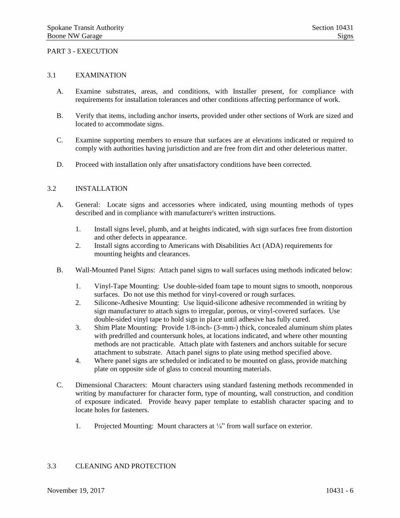
Spokane Transit Authority Section 10431
Boone NW Garage Signs
November 19, 2017 10431 - 6
PART 3 - EXECUTION
3.1 EXAMINATION
A. Examine substrates, areas, and conditions, with Installer present, for compliance with
requirements for installation tolerances and other conditions affecting performance of work.
B. Verify that items, including anchor inserts, provided under other sections of Work are sized and
located to accommodate signs.
C. Examine supporting members to ensure that surfaces are at elevations indicated or required to
comply with authorities having jurisdiction and are free from dirt and other deleterious matter.
D. Proceed with installation only after unsatisfactory conditions have been corrected.
3.2 INSTALLATION
A. General: Locate signs and accessories where indicated, using mounting methods of types
described and in compliance with manufacturer's written instructions.
1. Install signs level, plumb, and at heights indicated, with sign surfaces free from distortion
and other defects in appearance.
2. Install signs according to Americans with Disabilities Act (ADA) requirements for
mounting heights and clearances.
B. Wall-Mounted Panel Signs: Attach panel signs to wall surfaces using methods indicated below:
1. Vinyl-Tape Mounting: Use double-sided foam tape to mount signs to smooth, nonporous
surfaces. Do not use this method for vinyl-covered or rough surfaces.
2. Silicone-Adhesive Mounting: Use liquid-silicone adhesive recommended in writing by
sign manufacturer to attach signs to irregular, porous, or vinyl-covered surfaces. Use
double-sided vinyl tape to hold sign in place until adhesive has fully cured.
3. Shim Plate Mounting: Provide 1/8-inch- (3-mm-) thick, concealed aluminum shim plates
with predrilled and countersunk holes, at locations indicated, and where other mounting
methods are not practicable. Attach plate with fasteners and anchors suitable for secure
attachment to substrate. Attach panel signs to plate using method specified above.
4. Where panel signs are scheduled or indicated to be mounted on glass, provide matching
plate on opposite side of glass to conceal mounting materials.
C. Dimensional Characters: Mount characters using standard fastening methods recommended in
writing by manufacturer for character form, type of mounting, wall construction, and condition
of exposure indicated. Provide heavy paper template to establish character spacing and to
locate holes for fasteners.
1. Projected Mounting: Mount characters at ¼” from wall surface on exterior.
3.3 CLEANING AND PROTECTION

Spokane Transit Authority Section 10431
Boone NW Garage Signs
November 19, 2017 10431 - 7
A. After installation, clean soiled sign surfaces according to manufacturer's written instructions.
Protect signs from damage until acceptance by Owner.
END OF SECTION 101419
Spokane Transit Authority Section 10431
Boone NW Garage Signs
November 19, 2017 10431 - 8
THIS PAGE INTENTIONALLY LEFT BLANK

ALSC Project No. 2016-067STA Project No. 17-STA-579
Spokane Transit Authority Boone NW Garage
SIGNAGE SCHEDULE November 19, 2017 Page 1
Room No.
Owner's Room No. Room Name
Sign Type Qty Location Copy Remarks
501 FIRE 1 1 Latch side of door 101A FIRE See attached sign type 1 sheet
502 STORAGE 1 1 Latch side of door 102A STORAGE See attached sign type 1 sheet
503 COMMUNICATIONS 1 1 Latch side of door 103A COMMUNICATIONS See attached sign type 1 sheet
504 BUS STORAGE 1 1 Latch side of door 104A STORAGE See attached sign type 1 sheet
505 JANITORIAL 1 1 Latch side of door 105A JANITORIAL See attached sign type 1 sheet
506 RESTROOM 2 1 Latch side of door 106A ALL GENDER See attached sign type 2 sheet
507 RESTROOM 2 1 Latch side of door 107A ALL GENDER See attached sign type 2 sheet
508 BREAK ROOM 8 1 Latch side of door 108A BREAK ROOM See attached sign type 8 sheet
509 ELECTRICAL 1 1 Latch side of door 109A ELECTRICAL See attached sign type 1 sheet
3 34 2 @ ea. bus lane #, 31-47 See striping plans for locations
5 1 At front of wash bay PLEASE CLOSE WINDOWS AND HATCHES To be coordinated with owner
6 2 At south side of buildingKEEP OFF MAINTENENCE ACCESS ONLY NO STORAGE ALLOWED
See interior elevation sheet A-251
BUS EXIT 4 1 Right side of overhead door 110D 15 East side of building
BUS ENTRY 4 1 Left side of overhead door 110E 9 West side of building
BUS EXIT 4 1 Left side of overhead door 110F 10 West side of building
BUS EXIT 4 1 Left side of overhead door 110G 11 West side of building
BUS EXIT 4 1 Left side of overhead door 110H 12 West side of building
BUS EXIT 4 1 Left side of overhead door 110J 13 West side of building
BUS EXIT 4 1 Left side of overhead door 110K 14 West side of building
EXTERIOR 9 1 Right side of door 1224 West side of building
EXTERIOR 10 1 To be determined See attached sign type 10 sheet
INTERIOR 7 Fueling area (TBD) No smoking matches or open flames See attached sign type 7 sheet
1ST FLOOR
General Notes1. Refer to sheet titled "PANEL SIGN LOCATIONS" for typical mounting heights and distance from door frame.2. Where noted "Exterior Application" in Remarks column, provide weather resistant acrylic panel.
510 BUS STORAGE
ALSC Project No. 2016-067STA Project No. 17-STA-579
Spokane Transit Authority Boone NW Garage
SIGNAGE SCHEDULE November 19, 2017 Page 2
Room No.
Owner's Room No. Room Name
Sign Type Qty Location Copy Remarks
THIS PAGE INTENTIONALLY LEFT BLANK


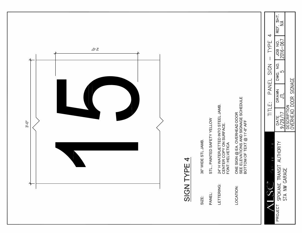


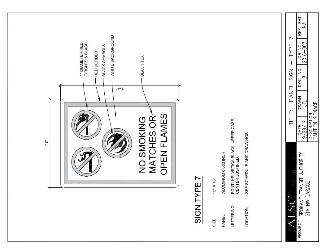

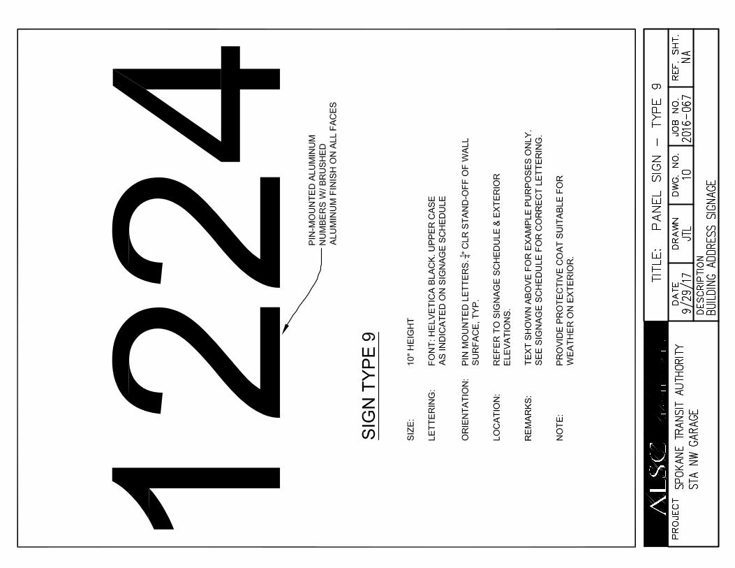
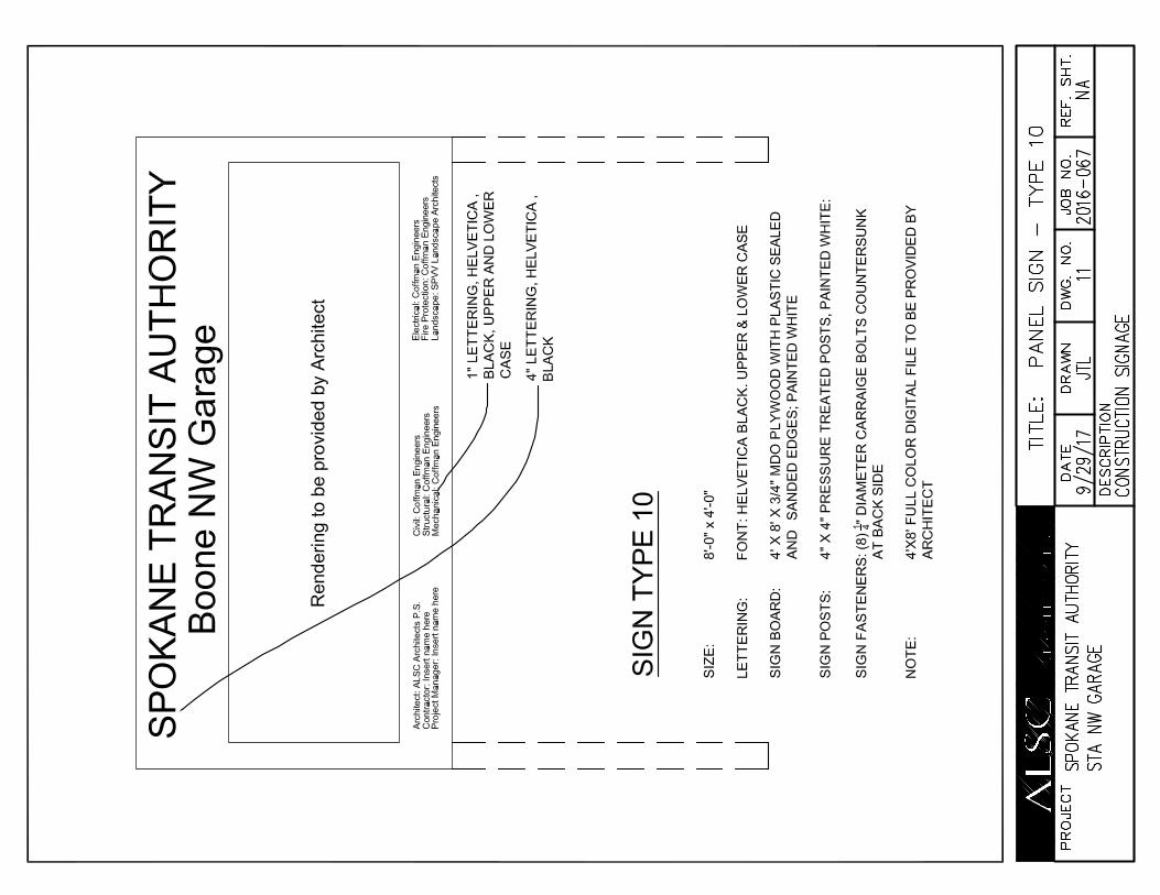
Spokane Transit Authority Section 102600 Boone NW Garage Wall and Door Protection
November 19, 2017 102600 - 1
SECTION 102600 - WALL AND DOOR PROTECTION
PART 1 - GENERAL
1.1 SUMMARY
A. Section Includes:
1. Corner guards.
1.2 ACTION SUBMITTALS
A. Product Data: For each type of product.
B. Samples: For each exposed product and for each color and texture specified, 12 inches long.
1.3 INFORMATIONAL SUBMITTALS
A. Product certificates.
B. Material certificates.
C. Sample warranty.
1.4 CLOSEOUT SUBMITTALS
A. Maintenance data.
PART 2 - PRODUCTS
2.1 MANUFACTURERS
A. Manufacturers: Provide subject to compliance with requirements, product by one of the following manufacturers:
1. Balco/Metalines, Wichita, KS.
2. Construction Specialties, Inc., Muncy, PA.
3. IPC Door and Wall Protection Systems, Muskego, WI.
4. Pawling Corporation, Wassaic, NY.
2.2 PERFORMANCE REQUIREMENTS
A. Surface Burning Characteristics: Comply with ASTM E 84 or UL 723; testing by a qualified testing agency. Identify products with appropriate markings of applicable testing agency.
1. Flame-Spread Index: 25 or less.
2. Smoke-Developed Index: 450 or less.

Spokane Transit Authority Section 102600 Boone NW Garage Wall and Door Protection
November 19, 2017 102600 - 2
B. Regulatory Requirements: Comply with applicable provisions in the U.S. Architectural & Transportation Barriers Compliance Board's ADA-ABA Accessibility Guidelines for Buildings and Facilities and ICC A117.1.
2.3 CORNER GUARDS
A. Surface-Mounted, Metal Corner Guards:
1. Design: Surface applied with fasteners.
2. Material: Stainless steel.
3. Wing Size: 1-1/2-inches.
4. Height: 8’-0” above finished floor.
5. Thickness: 16 gage.
6. Finish: No. 4 satin.
2.4 MATERIALS
A. Plastic Materials: Chemical- and stain-resistant, high-impact-resistant plastic with integral color throughout; extruded and sheet material as required, thickness as indicated.
B. Fasteners: Nonmagnetic stainless-steel, or other noncorrosive metal screws, bolts, and other fasteners compatible with items being fastened. Use security-type fasteners where exposed to view.
C. Adhesive: As recommended by protection product manufacturer.
PART 3 - EXECUTION
3.1 INSTALLATION
A. Installation Quality: Install according to manufacturer's written instructions, level, plumb, and true to line without distortions. Do not use materials with chips, cracks, voids, stains, or other defects that might be visible in the finished Work.
B. Mounting Heights: Install in locations and at mounting heights indicated on Drawings.
C. Accessories: Provide splices, mounting hardware, anchors, trim, joint moldings, and other accessories required for a complete installation.
1. Provide anchoring devices and suitable locations to withstand imposed loads.
END OF SECTION 102600

Spokane Transit Authority Section 102800 Boone NW Garage Toilet, Bath, and Laundry Accessories
November 19, 2017 102800 - 1
SECTION 102800 - TOILET, BATH, AND LAUNDRY ACCESSORIES
PART 1 - GENERAL
1.1 RELATED DOCUMENTS
A. Drawings and general provisions of the Contract, including General and Supplementary Conditions and Division 01 Specification Sections, apply to this Section.
1.2 SUMMARY
A. Section Includes:
1. Public-use washroom accessories. 2. Underlavatory guards. 3. Custodial accessories.
1.3 COORDINATION
A. Coordinate accessory locations with other work to prevent interference with clearances required for access by people with disabilities, and for proper installation, adjustment, operation, cleaning, and servicing of accessories.
B. Deliver inserts and anchoring devices set into concrete or masonry as required to prevent delaying the Work.
1.4 ACTION SUBMITTALS
A. Product Data: For each type of product.
1. Include construction details, material descriptions, dimensions of individual components and profiles, and finishes.
2. Include anchoring and mounting requirements, including requirements for cutouts in other work and substrate preparation.
3. Include electrical characteristics.
B. Samples: Full size, for each exposed product and for each finish specified.
1. Approved full-size Samples will be returned and may be used in the Work.
C. Product Schedule: Indicating types, quantities, sizes, and installation locations by room of each accessory required.
1. Identify locations using room designations indicated. 2. Identify accessories using designations indicated.
Spokane Transit Authority Section 102800 Boone NW Garage Toilet, Bath, and Laundry Accessories
November 19, 2017 102800 - 2
1.5 INFORMATIONAL SUBMITTALS
A. Sample Warranty: For manufacturer's special warranty.
1.6 CLOSEOUT SUBMITTALS
A. Maintenance Data: For accessories to include in maintenance manuals.
1.7 WARRANTY
A. Manufacturer's Special Warranty for Mirrors: Manufacturer agrees to repair or replace mirrors that fail in materials or workmanship within specified warranty period.
1. Failures include, but are not limited to, visible silver spoilage defects. 2. Warranty Period: 15 years from date of Substantial Completion.
PART 2 - PRODUCTS
2.1 OWNER-FURNISHED MATERIALS
A. Owner-Furnished Materials: <Insert products>.
2.2 PERFORMANCE REQUIREMENTS
A. Electrical Components, Devices, and Accessories: Listed and labeled as defined in NFPA 70, by a qualified testing agency, and marked for intended location and application.
2.3 PUBLIC-USE WASHROOM ACCESSORIES
A. Source Limitations: Obtain public-use washroom accessories from single source from single manufacturer.
B. Toilet Tissue (Roll) Dispenser: OFOI.
C. Grab Bar:
1. Manufacturers: Subject to compliance with requirements, provide products by one of the following:
a. AJW Architectural Products. b. American Specialties, Inc. c. Bobrick Washroom Equipment, Inc. d. Bradley Corporation. e. Brey-Krause Manufacturing Co. f. GAMCO Specialty Accessories; a division of Bobrick. g. Tubular Specialties Manufacturing, Inc.

Spokane Transit Authority Section 102800 Boone NW Garage Toilet, Bath, and Laundry Accessories
November 19, 2017 102800 - 3
2. Mounting: Flanges with exposed fasteners.
3. Material: Stainless steel, 0.05 inch (1.3 mm) thick.
a. Finish: Smooth, No. 4 finish (satin).
4. Outside Diameter: 1-1/2 inches (38 mm). 5. Configuration and Length: As indicated on Drawings.
D. Sanitary-Napkin Disposal Unit: OFOI.
E. Seat-Cover Dispenser: OFOI.
F. Mirror Unit: OFOI.
G. Coat Hook: OFOI.
2.4 UNDERLAVATORY GUARDS
A. Underlavatory Guard:
1. Manufacturers: Subject to compliance with requirements, provide products by one of the following:
a. Buckaroos, Inc. b. Plumberex Specialty Products, Inc. c. Truebro by IPS Corporation.
2. Description: Insulating pipe covering for supply and drain piping assemblies that prevents direct contact with and burns from piping; allow service access without removing coverings.
3. Material and Finish: Antimicrobial, molded plastic, white.
2.5 CUSTODIAL ACCESSORIES
A. Source Limitations: Obtain custodial accessories from single source from single manufacturer.
B. Mop and Broom Holder:
1. Manufacturers: Subject to compliance with requirements, provide products by one of the following:
a. AJW Architectural Products. b. American Specialties, Inc. c. Bobrick Washroom Equipment, Inc. d. Bradley Corporation.

Spokane Transit Authority Section 102800 Boone NW Garage Toilet, Bath, and Laundry Accessories
November 19, 2017 102800 - 4
e. Brey-Krause Manufacturing Co. f. GAMCO Specialty Accessories; a division of Bobrick. g. Tubular Specialties Manufacturing, Inc.
2. Description: Unit with hooks and holders. 3. Length: 36 inches (914 mm). 4. Hooks: Four. 5. Mop/Broom Holders: Three, spring-loaded, rubber hat, cam type. 6. Material and Finish: Stainless steel, No. 4 finish (satin).
2.6 MATERIALS
A. Stainless Steel: ASTM A 666, Type 304, 0.031-inch (0.8-mm) minimum nominal thickness unless otherwise indicated.
B. Brass: ASTM B 19, flat products; ASTM B 16/B 16M, rods, shapes, forgings, and flat products with finished edges; or ASTM B 30, castings.
C. Steel Sheet: ASTM A 1008/A 1008M, Designation CS (cold rolled, commercial steel), 0.036-inch (0.9-mm) minimum nominal thickness.
D. Galvanized-Steel Sheet: ASTM A 653/A 653M, with G60 (Z180) hot-dip zinc coating.
E. Galvanized-Steel Mounting Devices: ASTM A 153/A 153M, hot-dip galvanized after fabrication.
F. Fasteners: Screws, bolts, and other devices of same material as accessory unit and tamper-and-theft resistant where exposed, and of galvanized steel where concealed.
G. Chrome Plating: ASTM B 456, Service Condition Number SC 2 (moderate service).
H. Mirrors: ASTM C 1503, Mirror Glazing Quality, clear-glass mirrors, nominal 6.0 mm thick.
2.7 FABRICATION
A. General: Fabricate units with tight seams and joints, and exposed edges rolled. Hang doors and access panels with full-length, continuous hinges. Equip units for concealed anchorage and with corrosion-resistant backing plates.
PART 3 - EXECUTION
3.1 INSTALLATION
A. Install accessories according to manufacturers' written instructions, using fasteners appropriate to substrate indicated and recommended by unit manufacturer. Install units level, plumb, and firmly anchored in locations and at heights indicated.

Spokane Transit Authority Section 102800 Boone NW Garage Toilet, Bath, and Laundry Accessories
November 19, 2017 102800 - 5
B. Grab Bars: Install to withstand a downward load of at least 250 lbf (1112 N), when tested according to ASTM F 446.
3.2 ADJUSTING AND CLEANING
A. Adjust accessories for unencumbered, smooth operation. Replace damaged or defective items.
B. Remove temporary labels and protective coatings.
C. Clean and polish exposed surfaces according to manufacturer's written instructions.
END OF SECTION 102800
Spokane Transit Authority Section 102800 Boone NW Garage Toilet, Bath, and Laundry Accessories
November 19, 2017 102800 - 6
THIS PAGE INTENTIONALLY LEFT BLANK
Spokane Transit Authority Section 104413
Boone NW Garage Fire Protection Cabinets
November 19, 2017 104413 - 1
SECTION 104413 - FIRE PROTECTION CABINETS AND EXTINGUISHERS
PART 1 - GENERAL
1.1 RELATED DOCUMENTS
A. Drawings and general provisions of the Contract, including General and Supplementary
Conditions and Division 01 Specification Sections, apply to this Section.
1.2 SUMMARY
A. Section Includes:
1. Fire-protection cabinets for the following:
a. Portable fire extinguishers.
2. Portable Fire Extinguishers
1.3 ACTION SUBMITTALS
A. Product Data: For each type of product. Show door hardware, cabinet type, trim style, and panel
style. Include roughing-in dimensions and details showing recessed-, semirecessed-, or surface-
mounting method and relationships of box and trim to surrounding construction.
1. Show location of knockouts for hose valves.
B. Shop Drawings: For fire-protection cabinets. Include plans, elevations, sections, details, and
attachments to other work.
C. Product Schedule: For fire-protection cabinets. Indicate whether recessed, semirecessed, or
surface mounted. Coordinate final fire-protection cabinet schedule with fire-extinguisher
schedule to ensure proper fit and function.
1.4 CLOSEOUT SUBMITTALS
A. Maintenance Data: For fire-protection cabinets to include in maintenance manuals.
1.5 COORDINATION
A. Coordinate size of fire-protection cabinets to ensure that type and capacity of fire extinguishers
indicated are accommodated.

Spokane Transit Authority Section 104413
Boone NW Garage Fire Protection Cabinets
November 19, 2017 104413 - 2
PART 2 - PRODUCTS
2.1 FIRE-PROTECTION CABINET
A. Cabinet Type: Suitable for fire extinguisher.
1. Manufacturers: Subject to compliance with requirements, provide products by one of the
following:
a. Babcock-Davis.
b. Fire-End & Croker Corporation.
c. GMR International Equipment Corporation.
d. Guardian Fire Equipment, Inc.
e. JL Industries, Inc.; a division of the Activar Construction Products Group.
f. Larsens Manufacturing Company.
g. Modern Metal Products, Division of Technico Inc.
h. MOON American.
i. Nystrom, Inc.
j. Potter Roemer LLC.
k. Strike First Corporation of America (The).
B. Cabinet Construction: Nonrated.
C. Cabinet Material: Cold-rolled steel sheet.
1. Shelf: Same metal and finish as cabinet.
D. Surface-Mounted Cabinet: Cabinet box fully exposed and mounted directly on wall with no
trim.
E. Cabinet Trim Material: Steel sheet.
F. Door Material: Steel sheet.
G. Door Style: Vertical duo panel with frame.
H. Door Glazing: Tempered float glass (clear).
I. Door Hardware: Manufacturer's standard door-operating hardware of proper type for cabinet
type, trim style, and door material and style indicated.
1. Provide projecting door pull and manufacturer’s standard.
2. Provide continuous hinge, of same material and finish as trim, permitting door to open
180 degrees.
J. Accessories:
1. Mounting Bracket: Manufacturer's standard steel, designed to secure fire extinguisher to
fire-protection cabinet, of sizes required for types and capacities of fire extinguishers
indicated, with plated or baked-enamel finish.
Spokane Transit Authority Section 104413
Boone NW Garage Fire Protection Cabinets
November 19, 2017 104413 - 3
2. Identification: Lettering complying with authorities having jurisdiction for letter style,
size, spacing, and location. .
a. Identify fire extinguisher in fire-protection cabinet with the words "FIRE
EXTINGUISHER."
1) Location: Applied to cabinet door.
2) Application Process: Silk-screened.
3) Lettering Color: Red.
4) Orientation: Vertical.
K. Materials:
1. Cold-Rolled Steel: ASTM A 1008/A 1008M, Commercial Steel (CS), Type B.
a. Finish: Baked enamel or powder coat.
b. Color: As selected by Architect from full range of industry colors and color
densities.
2. Tempered Float Glass: ASTM C 1048, Kind FT, Condition A, Type I, Quality q3, 3 mm
thick, Class 1 (clear).
2.2 FABRICATION
A. Fire-Protection Cabinets: Provide manufacturer's standard box (tub) with trim, frame, door, and
hardware to suit cabinet type, trim style, and door style indicated.
1. Weld joints and grind smooth.
2. Provide factory-drilled mounting holes.
3. Prepare doors and frames to receive locks.
4. Install door locks at factory.
B. Cabinet Doors: Fabricate doors according to manufacturer's standards, from materials indicated
and coordinated with cabinet types and trim styles.
1. Fabricate door frames with tubular stiles and rails and hollow-metal design, minimum 13
mm (1/2 inch) thick.
2. Fabricate door frames of one-piece construction with edges flanged.
3. Miter and weld perimeter door frames.
C. Cabinet Trim: Fabricate cabinet trim in one piece with corners mitered, welded, and ground
smooth.
2.3 PORTABLE, HAND-CARRIED FIRE EXTINGUISHERS
A. Fire Extinguishers: Type, size, and capacity for each fire-protection cabinet and mounting
bracket indicated.
1. Manufacturers: Subject to compliance with requirements, provide product by one of the
following manufacturers:
a. JL Industries, Inc.

Spokane Transit Authority Section 104413
Boone NW Garage Fire Protection Cabinets
November 19, 2017 104413 - 4
b. Larsens Manufacturing Company
c. Nystrom
d. Potter Roemer LLC
2. Instruction Labels: Include pictorial marking system complying with NFPA 10,
Appendix B.
B. Multipurpose Dry-Chemical Type: UL-rated 2A-10B:C nominal capacity, with
monoammonium phosphate-based dry chemical in manufacturer’s standard enameled container.
C. Mounting Bracks: Manufacturer’s standard steel, designed to secure fire extinguisher to wall or
structure, of sizes required for types and capacities of fire extinguishers indicated, with plated or
black baked-enamel finish.
2.4 GENERAL FINISH REQUIREMENTS
A. Comply with NAAMM's AMP 500, "Metal Finishes Manual for Architectural and Metal
Products," for recommendations for applying and designating finishes.
B. Protect mechanical finishes on exposed surfaces of fire-protection cabinets from damage by
applying a strippable, temporary protective covering before shipping.
C. Finish fire-protection cabinets after assembly.
D. Appearance of Finished Work: Noticeable variations in same piece are not acceptable.
Variations in appearance of adjoining components are acceptable if they are within the range of
approved Samples and are assembled or installed to minimize contrast.
PART 3 - EXECUTION
3.1 EXAMINATION
A. Examine roughing-in for hose valves, racks and cabinets to verify actual locations of piping
connections before cabinet installation.
B. Examine walls and partitions for suitable blocking where cabinets will be installed.
C. Proceed with installation only after unsatisfactory conditions have been corrected.
3.2 INSTALLATION
A. General: Install fire-protection cabinets in locations and at mounting heights indicated[ or, if not
indicated, at heights indicated below:][ or, if not indicated, at heights acceptable to authorities
having jurisdiction.]
1. Fire-Protection Cabinets: 1372 mm (54 inches) above finished floor to top of cabinet.
B. Fire-Protection Cabinets: Fasten cabinets to structure, square and plumb.
1. Fasten mounting brackets to inside surface of fire-protection cabinets, square and plumb.

Spokane Transit Authority Section 104413
Boone NW Garage Fire Protection Cabinets
November 19, 2017 104413 - 5
C. Identification: Apply vinyl lettering at locations indicated.
3.3 ADJUSTING AND CLEANING
A. Remove temporary protective coverings and strippable films, if any, as fire-protection cabinets
are installed unless otherwise indicated in manufacturer's written installation instructions.
B. Adjust fire-protection cabinet doors to operate easily without binding. Verify that integral
locking devices operate properly.
C. On completion of fire-protection cabinet installation, clean interior and exterior surfaces as
recommended by manufacturer.
D. Touch up marred finishes, or replace fire-protection cabinets that cannot be restored to factory-
finished appearance. Use only materials and procedures recommended or furnished by fire-
protection cabinet and mounting bracket manufacturers.
E. Replace fire-protection cabinets that have been damaged or have deteriorated beyond successful
repair by finish touchup or similar minor repair procedures.
END OF SECTION 104413
Spokane Transit Authority Section 104413
Boone NW Garage Fire Protection Cabinets
November 19, 2017 104413 - 6
THIS PAGE INTENTIONALLY LEFT BLANK

Sp o k a n e Tr a n sit Au t h o r it y Sect io n 1 0 5 0 0 0
Bo o n e NW Ga r a ge Misce lla n eo u s Sp ecia lt ie s
No vem b er 1 9 , 2 0 1 7 1 0 5 0 0 0 - 1
SECTION 10 50 00 - MISCELLANEOUS SPECIALTIES PART 1 - GENERAL
1.1 RELATED DOCUMENTS
A. Drawings and general provisions of the Contract, including General and Supplementary Conditions and Division 01 Specification Sections, apply to this Section.
B. Refer to Division 1 Section “Sustainable Design Requirements – WSSP for Schools” for submittal requirements and formats.
1.2 SUMMARY A. This Section includes the following:
1. Circular convex mirror and wall mount. 1.3 SUBMITTALS
A. General: Submit the following according to Conditions of the Contract and Division 1
Specification Sections. 1. Product data for specified items including rough-in dimensions, details showing
mounting methods, relationships to surrounding construction, hardware, and materials. PART 2 - PRODUCTS 2.1 MANUFACTURERS
A. Products: Specification is based on the products listed. Subject to compliance with
requirements and properties of the products listed, products by other manufacturers will be considered if submitted in accordance with the stipulations in the Invitation for Subcontractor Bids.
2.2 CIRCULAR CONVEX MIRRORS
A. Basis of design manufacturer: Global Industrial a Systemax Company, Safety Security Products, SGB502859.
B. Description 1. Circular convex mirror. 2. Wall / steel structure mounted. Adjustable steel wall mount hardware. 3. Diameter: 26 inches. 4. Type: Indoor / outdoor. 5. Construction: Polycarbonate. 6. Backing: Molded Polycarbonate.

Sp o k a n e Tr a n sit Au t h o r it y Sect io n 1 0 5 0 0 0
Bo o n e NW Ga r a ge Misce lla n eo u s Sp ecia lt ie s
No vem b er 1 9 , 2 0 1 7 1 0 5 0 0 0 - 2
PART 3 - EXECUTION 3.1 INSTALLATION GENERAL
A. Follow manufacturer's printed instructions for installation. B. Locate as indicated, or if not indicated, as directed.
3.2 ADJUST AND CLEAN
A. Adjust Specialties having operating features after installation for proper operation. B. Remove and replace specialties that are damaged.
END OF SECTION 10 50 00

Spokane Transit Authority Section 133419
Boone NW Garage Metal Building Systems
November 19, 2017 133419 - 1
SECTION 133419 - METAL BUILDING SYSTEMS
PART 1 - GENERAL
1.1 RELATED DOCUMENTS
A. Drawings and general provisions of the Contract, including General and Supplementary
Conditions and Division 01 Specification Sections, apply to this Section.
1.2 SUMMARY
A. Section Includes:
1. Structural-steel framing.
2. Structural framing and supports for overhead doors.
3. Metal roof panels.
4. Thermal insulation.
5. Accessories.
B. Related Requirements:
1. Section 077253 "Snow Guards" for prefabricated devices designed to hold snow on the
roof surface.
2. Section 083323.13 "High Performance Overhead Coiling Doors" for coiling vehicular
doors in metal building systems.
1.3 DEFINITIONS
A. Terminology Standard: See MBMA's "Metal Building Systems Manual" for definitions of terms
for metal building system construction not otherwise defined in this Section or in standards
referenced by this Section.
1.4 COORDINATION
A. Coordinate sizes and locations of concrete foundations and casting of anchor-rod inserts into
foundation walls and footings. Anchor rod installation, concrete, reinforcement, and formwork
requirements are specified in Section 033000 "Cast-in-Place Concrete."
B. Coordinate metal panel assemblies with rain drainage work, flashing, trim, and construction of
supports and other adjoining work to provide a leakproof, secure, and noncorrosive installation.
1.5 PREINSTALLATION MEETINGS
A. Preinstallation Conference: Conduct conference at Project site.

Spokane Transit Authority Section 133419
Boone NW Garage Metal Building Systems
November 19, 2017 133419 - 2
1. Review methods and procedures related to metal building systems including, but not
limited to, the following:
a. Condition of foundations and other preparatory work performed by other trades.
b. Structural load limitations.
c. Construction schedule. Verify availability of materials and erector's personnel,
equipment, and facilities needed to make progress and avoid delays.
d. Required tests, inspections, and certifications.
e. Unfavorable weather and forecasted weather conditions and impact on
construction schedule.
2. Review methods and procedures related to metal roof panel assemblies including, but not
limited to, the following:
a. Compliance with requirements for purlin and rafter conditions, including flatness
and attachment to structural members.
b. Structural limitations of purlins and rafters during and after roofing.
c. Flashings, special roof details, roof drainage, roof penetrations, equipment curbs,
and condition of other construction that will affect metal roof panels.
d. Temporary protection requirements for metal roof panel assembly during and after
installation.
e. Roof observation and repair after metal roof panel installation.
3. Review methods and procedures related to metal wall panel assemblies including, but not
limited to, the following:
a. Compliance with requirements for support conditions, including alignment
between and attachment to structural members.
b. Structural limitations of girts and columns during and after wall panel installation.
c. Flashings, special siding details, wall penetrations, openings, and condition of
other construction that will affect metal wall panels.
d. Temporary protection requirements for metal wall panel assembly during and after
installation.
e. Wall observation and repair after metal wall panel installation.
1.6 ACTION SUBMITTALS
A. Product Data: For each type of metal building system component.
1. Include construction details, material descriptions, dimensions of individual components
and profiles, and finishes for the following:
a. Metal roof panels.
b. Thermal insulation and vapor-retarder facings.
B. Shop Drawings: Indicate components by others. Include full building plan, elevations, sections,
details and the following:
1. Anchor-Rod Plans: Submit anchor-rod plans and templates before foundation work
begins. Include location, diameter, and minimum required projection of anchor rods
Spokane Transit Authority Section 133419
Boone NW Garage Metal Building Systems
November 19, 2017 133419 - 3
required to attach metal building to foundation. Indicate column reactions at each
location.
2. Structural-Framing Drawings: Show complete fabrication of primary and secondary
framing; include provisions for openings. Indicate welds and bolted connections,
distinguishing between shop and field applications. Include transverse cross-sections.
3. Metal Roof Panel Layout Drawings: Show layouts of panels including methods of
support. Include details of edge conditions, joints, panel profiles, corners, anchorages,
clip spacing, trim, flashings, closures, and special details. Distinguish between factory-
and field-assembled work; show locations of exposed fasteners.
a. Show roof-mounted items including roof hatches, pipe supports and penetrations.
4. Accessory Drawings: Include details, at a scale of not less than 1-1/2 inches per 12 inches
(1:8):
C. Samples for Initial Selection: For units with factory-applied finishes.
D. Samples for Verification: For the following products:
1. Panels: Nominal 12 inches (300 mm) long by actual panel width. Include fasteners,
closures, and other exposed panel accessories.
2. Flashing and Trim: Nominal 12 inches (300 mm) long. Include fasteners and other
exposed accessories.
3. Vapor-Retarder Facings: Nominal 6-inch- (150-mm-) square Samples.
4. Accessories: Nominal 12-inch- (300-mm-) long Samples for each type of accessory.
E. Delegated-Design Submittal: For metal building systems.
1. Include analysis data indicating compliance with performance requirements and design
data signed and sealed by the qualified professional engineer responsible for their
preparation.
1.7 INFORMATIONAL SUBMITTALS
A. Qualification Data: For erector and manufacturer.
B. Welding certificates.
C. Letter of Design Certification: Signed and sealed by a qualified professional engineer. Include
the following:
1. Name and location of Project.
2. Order number.
3. Name of manufacturer.
4. Name of Contractor.
5. Building dimensions including width, length, height, and roof slope.
6. Indicate compliance with AISC standards for hot-rolled steel and AISI standards for cold-
rolled steel, including edition dates of each standard.
7. Governing building code and year of edition.

Spokane Transit Authority Section 133419
Boone NW Garage Metal Building Systems
November 19, 2017 133419 - 4
8. Design Loads: Include dead load, roof live load, collateral loads, roof snow load,
deflection, wind loads/speeds and exposure, seismic design category or effective peak
velocity-related acceleration/peak acceleration, and auxiliary loads (cranes).
9. Load Combinations: Indicate that loads were applied acting simultaneously with
concentrated loads, according to governing building code.
10. Building-Use Category: Indicate category of building use and its effect on load
importance factors.
D. Erector Certificates: For qualified erector, from manufacturer.
E. Material Test Reports: For each of the following products:
1. Structural steel including chemical and physical properties.
2. Bolts, nuts, and washers including mechanical properties and chemical analysis.
3. Tension-control, high-strength, bolt-nut-washer assemblies.
4. Shop primers.
5. Nonshrink grout.
F. Source quality-control reports.
G. Field quality-control reports.
H. Surveys: Show final elevations and locations of major members. Indicate discrepancies between
actual installation and the Contract Documents. Have surveyor who performed surveys certify
their accuracy.
I. Sample Warranties: For special warranties.
1.8 CLOSEOUT SUBMITTALS
A. Maintenance Data: For metal panel finishes to include in maintenance manuals.
1.9 QUALITY ASSURANCE
A. Manufacturer Qualifications: A qualified manufacturer.
1. Accreditation: Manufacturer's facility accredited according to the International
Accreditation Service's AC472, "Accreditation Criteria for Inspection Programs for
Manufacturers of Metal Building Systems."
2. Engineering Responsibility: Preparation of comprehensive engineering analysis and Shop
Drawings by a professional engineer who is legally qualified to practice in jurisdiction
where Project is located.
B. Erector Qualifications: An experienced erector who specializes in erecting and installing work
similar in material, design, and extent to that indicated for this Project and who is acceptable to
manufacturer.
C. Welding Qualifications: Qualify procedures and personnel according to the following:
1. AWS D1.1/D1.1M, "Structural Welding Code - Steel."

Spokane Transit Authority Section 133419
Boone NW Garage Metal Building Systems
November 19, 2017 133419 - 5
2. AWS D1.3, "Structural Welding Code - Sheet Steel."
D. Land Surveyor Qualifications: A professional land surveyor who practices in jurisdiction where
Project is located and who is experienced in providing surveying services of the kind indicated.
1.10 DELIVERY, STORAGE, AND HANDLING
A. Deliver components, sheets, panels, and other manufactured items so as not to be damaged or
deformed. Package metal panels for protection during transportation and handling.
B. Unload, store, and erect metal panels in a manner to prevent bending, warping, twisting, and
surface damage.
C. Stack metal panels horizontally on platforms or pallets, covered with suitable weathertight and
ventilated covering. Store metal panels to ensure dryness, with positive slope for drainage of
water. Do not store metal panels in contact with other materials that might cause staining,
denting, or other surface damage.
D. Protect foam-plastic insulation as follows:
1. Do not expose to sunlight, except to extent necessary for period of installation and
concealment.
2. Protect against ignition at all times. Do not deliver foam-plastic insulation materials to
Project site before installation time.
3. Complete installation and concealment of foam-plastic materials as rapidly as possible in
each area of construction.
1.11 FIELD CONDITIONS
A. Weather Limitations: Proceed with panel installation only when weather conditions permit
metal panels to be installed according to manufacturers' written instructions and warranty
requirements.
1.12 WARRANTY
A. Special Weathertightness Warranty for Standing-Seam Metal Roof Panels: Manufacturer agrees
to repair or replace standing-seam metal roof panel assemblies that leak or otherwise fail to
remain weathertight within specified warranty period.
1. Warranty Period: 20 years from date of Substantial Completion.
PART 2 - PRODUCTS
2.1 MANUFACTURERS
A. Manufacturers: Subject to compliance with requirements, provide products by one of the
following:
Spokane Transit Authority Section 133419
Boone NW Garage Metal Building Systems
November 19, 2017 133419 - 6
1. American Buildings Company; a Nucor Company.
2. Butler Manufacturing Company; a division of BlueScope Buildings North America, Inc.
3. CBC Steel Buildings; a Nucor Company.
4. Garco Building Systems; a division of NCI.
5. Mesco Building Solutions; a division of NCI Building Systems, Inc.
6. Nucor Building Systems.
7. Varco Pruden Buildings.
B. Source Limitations: Obtain metal building system components, including primary and
secondary framing and metal panel assemblies, from single source from single manufacturer.
2.2 SYSTEM DESCRIPTION
A. Provide a complete, integrated set of mutually dependent components and assemblies that form
a metal building system capable of withstanding structural and other loads, thermally induced
movement, and exposure to weather without failure or infiltration of water into building
interior.
B. Primary-Frame Type:
1. Rigid Modular: Solid-member, structural-framing system with interior columns.
C. End-Wall Framing: Manufacturer's standard, for buildings not required to be expandable,
consisting of primary frame, capable of supporting one-half of a bay design load, and end-wall
columns.
D. End-Wall Framing: Engineer end walls to be expandable. Provide primary frame, capable of
supporting full-bay design loads, and end-wall columns.
E. Secondary-Frame Type: Manufacturer's standard purlins and joists and exterior-framed (bypass)
girts.
F. Eave Height: As indicated on the drawings.
G. Bay Spacing: As indicated on Drawings.
H. Roof Slope: 3/8 inch per 12 inches (1:32).
I. Roof System: Manufacturer's standard standing-seam, trapezoidal-rib, metal roof panels.
2.3 PERFORMANCE REQUIREMENTS
A. Delegated Design: Engage a qualified professional engineer, as defined in Section 014000
"Quality Requirements," to design metal building system.
B. Structural Performance: Metal building systems shall withstand the effects of gravity loads and
the following loads and stresses within limits and under conditions indicated according to
procedures in MBMA's "Metal Building Systems Manual."
Spokane Transit Authority Section 133419
Boone NW Garage Metal Building Systems
November 19, 2017 133419 - 7
1. Design Loads: As indicated on Drawings.
2. Deflection and Drift Limits: Design metal building system assemblies to withstand
serviceability design loads without exceeding deflections and drift limits recommended in
AISC Steel Design Guide No. 3 "Serviceability Design Considerations for Steel
Buildings."
3. Deflection and Drift Limits: No greater than the following:
a. Purlins and Rafters: Vertical deflection of 1/240 of the span.
b. Girts: Horizontal deflection of 1/240 of the span.
c. Metal Roof Panels: Vertical deflection of 1/240 of the span.
d. Metal Wall Panels: Horizontal deflection of 1/240 of the span.
e. Design secondary-framing system to accommodate deflection of primary framing
and construction tolerances, and to maintain clearances at openings.
f. Lateral Drift: Maximum of [1/60] [1/100] [1/200] [1/400] <Insert limit> of the
building height.
C. Seismic Performance: Metal building system shall withstand the effects of earthquake motions
determined according to ASCE/SEI 7.
D. Thermal Movements: Allow for thermal movements from ambient and surface temperature
changes by preventing buckling, opening of joints, overstressing of components, failure of joint
sealants, failure of connections, and other detrimental effects. Base calculations on surface
temperatures of materials due to both solar heat gain and nighttime-sky heat loss.
1. Temperature Change: 120 deg F (67 deg C), ambient; 180 deg F (100 deg C), material
surfaces.
E. Structural Performance for Metal Roof Panels: Provide metal panel systems capable of
withstanding the effects of the following loads, based on testing according to ASTM E 1592:
1. Wind Loads: As indicated on Drawings.
F. Air Infiltration for Metal Roof Panels: Air leakage of not more than 0.06 cfm/sq. ft. (0.3 L/s per
sq. m) when tested according to ASTM E 1680[ or ASTM E 283] at the following test-pressure
difference:
1. Test-Pressure Difference: 1.57 lbf/sq. ft. (75 Pa).
G. Air Infiltration for Metal Wall Panels: Air leakage of not more than 0.06 cfm/sq. ft. (0.3 L/s per
sq. m) when tested according to ASTM E 283 at the following test-pressure difference:
1. Test-Pressure Difference: 1.57 lbf/sq. ft. (75 Pa).
H. Water Penetration for Metal Roof Panels: No water penetration when tested according to
ASTM E 1646[ or ASTM E 331] at the following test-pressure difference:
1. Test-Pressure Difference: 2.86 lbf/sq. ft. (137 Pa).
I. Wind-Uplift Resistance: Provide metal roof panel assemblies that comply with UL 580 for
wind-uplift-resistance class indicated.
Spokane Transit Authority Section 133419
Boone NW Garage Metal Building Systems
November 19, 2017 133419 - 8
1. Uplift Rating: UL 60.
J. Thermal Performance for Opaque Elements: Provide the following maximum U-factors when
tested according to ASTM C 1363 or ASTM C 518:
1. Roof:
a. U-Factor: 0.031.
2.4 STRUCTURAL-STEEL FRAMING
A. Structural Steel: Comply with AISC 360, "Specification for Structural Steel Buildings."
B. Bolted Connections: Comply with RCSC's "Specification for Structural Joints Using High-
Strength Bolts."
C. Cold-Formed Steel: Comply with AISI's "North American Specification for the Design of Cold-
Formed Steel Structural Members" for design requirements and allowable stresses.
D. Primary Framing: Manufacturer's standard primary-framing system, designed to withstand
required loads and specified requirements. Primary framing includes transverse and lean-to
frames; rafters, rake, and canopy beams; sidewall, intermediate, end-wall, and corner columns;
and wind bracing.
1. General: Provide frames with attachment plates, bearing plates, and splice members.
Factory drill for field-bolted assembly. Provide frame span and spacing indicated.
a. Slight variations in span and spacing may be acceptable if necessary to comply
with manufacturer's standard, as approved by Architect.
2. Long-Bay Frames: I-shaped frame sections fabricated from shop-welded, built-up steel
plates or structural-steel shapes. Provide interior columns fabricated from round steel
pipes or tubes, or shop-welded, built-up steel plates.
3. Frame Configuration: Single gable.
4. Exterior Column: Tapered.
5. Rafter: Tapered.
E. End-Wall Framing: Manufacturer's standard primary end-wall framing fabricated for field-
bolted assembly to comply with the following:
1. End-Wall and Corner Columns: I-shaped sections fabricated from structural-steel shapes;
shop-welded, built-up steel plates; or C-shaped, cold-formed, structural-steel sheet.
2. End-Wall Rafters: C-shaped, cold-formed, structural-steel sheet; or I-shaped sections
fabricated from shop-welded, built-up steel plates or structural-steel shapes.
F. Secondary Framing: Manufacturer's standard secondary framing, including purlins, girts, eave
struts, flange bracing, base members, gable angles, clips, headers, jambs, and other
miscellaneous structural members. Unless otherwise indicated, fabricate framing from either
cold-formed, structural-steel sheet or roll-formed, metallic-coated steel sheet, prepainted with
coil coating, to comply with the following:

Spokane Transit Authority Section 133419
Boone NW Garage Metal Building Systems
November 19, 2017 133419 - 9
1. Purlins: C- or Z-shaped sections; fabricated from built-up steel plates, steel sheet, or
structural-steel shapes; minimum 2-1/2-inch- (64-mm-) wide flanges.
a. Depth: As indicated on Drawings.
2. Purlins: Steel joists of depths indicated on Drawings.
3. Girts: C- or Z-shaped sections; fabricated from built-up steel plates, steel sheet, or
structural-steel shapes. Form ends of Z-sections with stiffening lips angled 40 to 50
degrees from flange, with minimum 2-1/2-inch- (64-mm-) wide flanges.
a. Depth: As required to comply with system performance requirements.
4. Eave Struts: Unequal-flange, C-shaped sections; fabricated from built-up steel plates,
steel sheet, or structural-steel shapes; to provide adequate backup for metal panels.
5. Flange Bracing: Minimum 2-by-2-by-1/8-inch (51-by-51-by-3-mm) structural-steel
angles or 1-inch- (25-mm-) diameter, cold-formed structural tubing to stiffen primary-
frame flanges.
6. Sag Bracing: Minimum 1-by-1-by-1/8-inch (25-by-25-by-3-mm) structural-steel angles.
7. Base or Sill Angles: Manufacturer's standard base angle, minimum 3-by-2-inch (76-by-
51-mm), fabricated from zinc-coated (galvanized) steel sheet.
8. Purlin and Girt Clips: Manufacturer's standard clips fabricated from steel sheet. Provide
galvanized clips where clips are connected to galvanized framing members.
9. Framing for Openings: Channel shapes; fabricated from cold-formed, structural-steel
sheet or structural-steel shapes. Frame head and jamb of door openings and head, jamb,
and sill of other openings.
10. Miscellaneous Structural Members: Manufacturer's standard sections fabricated from
cold-formed, structural-steel sheet; built-up steel plates; or zinc-coated (galvanized) steel
sheet; designed to withstand required loads.
G. Bracing: Provide adjustable wind bracing using any method as follows:
1. Rods: ASTM A 36/A 36M; ASTM A 572/A 572M, Grade 50 (345); or
ASTM A 529/A 529M, Grade 50 (345); minimum 1/2-inch- (13-mm-) diameter steel;
threaded full length or threaded a minimum of 6 inches (152 mm) at each end.
2. Cable: ASTM A 475, minimum 1/4-inch- (6-mm-) diameter, extra-high-strength grade,
Class B, zinc-coated, seven-strand steel; with threaded end anchors.
3. Angles: Fabricated from structural-steel shapes to match primary framing, of size
required to withstand design loads.
4. Rigid Portal Frames: Fabricated from shop-welded, built-up steel plates or structural-steel
shapes to match primary framing; of size required to withstand design loads.
5. Fixed-Base Columns: Fabricated from shop-welded, built-up steel plates or structural-
steel shapes to match primary framing; of size required to withstand design loads.
6. Diaphragm Action of Metal Panels: Design metal building to resist wind forces through
diaphragm action of metal panels.
H. Anchor Rods: Headed anchor rods as indicated in Anchor Rod Plan for attachment of metal
building to foundation.
I. Materials:
Spokane Transit Authority Section 133419
Boone NW Garage Metal Building Systems
November 19, 2017 133419 - 10
1. W-Shapes: ASTM A 992/A 992M; ASTM A 572/A 572M, Grade 50 or 55 (345 or 380);
or ASTM A 529/A 529M, Grade 50 or 55 (345 or 380).
2. Channels, Angles, M-Shapes, and S-Shapes: ASTM A 36/A 36M;
ASTM A 572/A 572M, Grade 50 or 55 (345 or 380); or ASTM A 529/A 529M, Grade 50
or 55 (345 or 380).
3. Plate and Bar: ASTM A 36/A 36M; ASTM A 572/A 572M, Grade 50 or 55 (345 or 380);
or ASTM A 529/A 529M, Grade 50 or 55 (345 or 380).
4. Steel Pipe: ASTM A 53/A 53M, Type E or S, Grade B.
5. Cold-Formed Hollow Structural Sections: ASTM A 500, Grade B or C, structural tubing.
6. Structural-Steel Sheet: Hot-rolled, ASTM A 1011/A 1011M, Structural Steel (SS),
Grades 30 through 55 (205 through 380), or High-Strength Low-Alloy Steel (HSLAS) or
High-Strength Low-Alloy Steel with Improved Formability (HSLAS-F), Grades 45
through 70 (310 through 480); or cold-rolled, ASTM A 1008/A 1008M, Structural Steel
(SS), Grades 25 through 80 (170 through 550), or HSLAS, Grades 45 through 70 (310
through 480).
7. Metallic-Coated Steel Sheet: ASTM A 653/A 653M, SS, Grades 33 through 80 (230
through 550), or HSLAS or HSLAS-F, Grades 50 through 80 (340 through 550); with
G60 (Z180) coating designation; mill phosphatized.
8. Metallic-Coated Steel Sheet Prepainted with Coil Coating: Steel sheet, metallic coated by
the hot-dip process and prepainted by the coil-coating process to comply with
ASTM A 755/A 755M.
a. Zinc-Coated (Galvanized) Steel Sheet: ASTM A 653/A 653M, SS, Grades 33
through 80 (230 through 550), or HSLAS or HSLAS-F, Grades 50 through 80 (340
through 550); with G90 (Z275) coating designation.
b. Aluminum-Zinc Alloy-Coated Steel Sheet: ASTM A 792/A 792M, SS, Grade 50
or 80 (340 or 550); with Class AZ50 (AZM150) coating.
9. Joist Girders: Manufactured according to "Standard Specifications for Joist Girders," in
SJI's "Standard Specifications and Load Tables for Steel Joists and Joist Girders"; with
steel-angle, top- and bottom-chord members, and end- and top-chord arrangements as
indicated on Drawings and required for primary framing.
10. Steel Joists: Manufactured according to "Standard Specifications for Open Web Steel
Joists, K-Series," in SJI's "Standard Specifications and Load Tables for Steel Joists and
Joist Girders"; with steel-angle, top- and bottom-chord members, and end- and top-chord
arrangements as indicated on Drawings and required for secondary framing.
11. Non-High-Strength Bolts, Nuts, and Washers: ASTM A 307, Grade A, carbon-steel, hex-
head bolts; ASTM A 563 (ASTM A 563M) carbon-steel hex nuts; and ASTM F 844 plain
(flat) steel washers.
a. Finish: Hot-dip zinc coating, ASTM F 2329, Class C.
12. Structural Bolts, Nuts, and Washers: ASTM A 325 (ASTM A 325M), Type 1, heavy-hex
steel structural bolts; ASTM A 563 (ASTM A 563M) heavy-hex carbon-steel nuts; and
ASTM F 436 (ASTM F 436M) hardened carbon-steel washers.
a. Finish: Hot-dip zinc coating, ASTM F 2329, Class C.
13. High-Strength Bolts, Nuts, and Washers: ASTM A 490 (ASTM A 490M), Type 1, heavy-
hex steel structural bolts or tension-control, bolt-nut-washer assemblies with spline ends;

Spokane Transit Authority Section 133419
Boone NW Garage Metal Building Systems
November 19, 2017 133419 - 11
ASTM A 563 (ASTM A 563M) heavy-hex carbon-steel nuts; and ASTM F 436
(ASTM F 436M) hardened carbon-steel washers, plain.
14. Tension-Control, High-Strength Bolt-Nut-Washer Assemblies: ASTM F 1852, Type 1,
heavy-hex-head steel structural bolts with spline ends.
a. Finish: Mechanically deposited zinc coating, ASTM B 695, Class 50.
15. Unheaded Anchor Rods: ASTM F 1554, Grade 36.
a. Configuration: Straight.
b. Nuts: ASTM A 563 (ASTM A 563M) heavy-hex carbon steel.
c. Plate Washers: ASTM A 36/A 36M carbon steel.
d. Washers: ASTM F 436 (ASTM F 436M) hardened carbon steel.
e. Finish: Hot-dip zinc coating, ASTM F 2329, Class C.
16. Headed Anchor Rods: ASTM F 1554, Grade 36.
a. Configuration: Straight.
b. Nuts: ASTM A 563 (ASTM A 563M) heavy-hex carbon steel.
c. Plate Washers: ASTM A 36/A 36M carbon steel.
d. Washers: ASTM F 436 (ASTM F 436M) hardened carbon steel.
e. Finish: Hot-dip zinc coating, ASTM F 2329, Class C.
17. Threaded Rods: ASTM A 36/A 36M.
a. Nuts: ASTM A 563 (ASTM A 563M) heavy-hex carbon steel.
b. Washers: ASTM A 36/A 36M carbon steel.
c. Finish: Hot-dip zinc coating, ASTM F 2329, Class C.
J. Finish: Factory primed. Apply specified primer immediately after cleaning and pretreating.
1. Clean and prepare in accordance with SSPC-SP2.
2. Coat with manufacturer's standard primer. Apply primer to primary and secondary
framing to a minimum dry film thickness of 1 mil (0.025 mm).
a. Prime secondary framing formed from uncoated steel sheet to a minimum dry film
thickness of 0.5 mil (0.013 mm) on each side.
2.5 METAL ROOF PANELS
A. Standing-Seam, Trapezoidal-Rib, Metal Roof Panels: Formed with raised trapezoidal ribs at
panel edges and flat pan between ribs; designed for sequential installation by mechanically
attaching panels to supports using concealed clips located under one side of panels and
engaging opposite edge of adjacent panels.
1. Material: Zinc-coated (galvanized) or aluminum-zinc alloy-coated steel sheet, 0.030-inch
(0.76-mm) nominal uncoated steel thickness.
2. Clips: Two-piece floating to accommodate thermal movement.
3. Joint Type: Mechanically seamed.
4. Panel Coverage: 24 inches (610 mm).

Spokane Transit Authority Section 133419
Boone NW Garage Metal Building Systems
November 19, 2017 133419 - 12
5. Panel Height: 3 inches (76 mm).
6. Uplift Rating: UL 60.
2.6 THERMAL INSULATION
A. Faced Metal Building Insulation: ASTM C 991, Type II, glass-fiber-blanket insulation; 0.5-
lb/cu. ft. (8-kg/cu. m) density; 2-inch- (51-mm-) wide, continuous, vapor-tight edge tabs; with a
flame-spread index of 25 or less.
B. Mineral-Fiber-Blanket Insulation: ASTM C 665, type indicated below; consisting of fibers
manufactured from glass, slag wool, or rock wool.
1. Nonreflective Faced: Type II (blankets with nonreflective membrane covering),
Category 1 (membrane is a vapor retarder), Class A (membrane-faced surface with a
flame-spread index of 25 or less).
C. Retainer Strips: For securing insulation between supports, 0.025-inch (0.64-mm) nominal-
thickness, formed, metallic-coated steel or PVC retainer clips colored to match insulation
facing.
D. Vapor-Retarder Facing: ASTM C 1136, with permeance not greater than 0.02 perm (1.15 ng/Pa
x s x sq. m) when tested according to ASTM E 96/E 96M, Desiccant Method.
1. Composition: White polypropylene or vinyl film facing, fiberglass scrim reinforcement,
and metallized-polyester film backing.
2. Composition: White polypropylene film facing and fiberglass-polyester-blend fabric
backing.
E. Vapor-Retarder Tape: Pressure-sensitive tape of type recommended by vapor-retarder
manufacturer for sealing joints and penetrations in vapor retarder.
2.7 ACCESSORIES
A. General: Provide accessories as standard with metal building system manufacturer and as
specified. Fabricate and finish accessories at the factory to greatest extent possible, by
manufacturer's standard procedures and processes. Comply with indicated profiles and with
dimensional and structural requirements.
1. Form exposed sheet metal accessories that are without excessive oil-canning, buckling,
and tool marks and that are true to line and levels indicated, with exposed edges folded
back to form hems.
B. Roof Panel Accessories: Provide components required for a complete metal roof panel assembly
including copings, fasciae, corner units, ridge closures, clips, sealants, gaskets, fillers, closure
strips, and similar items. Match material and finish of metal roof panels unless otherwise
indicated.
1. Closures: Provide closures at eaves and ridges, fabricated of same material as metal roof
panels.

Spokane Transit Authority Section 133419
Boone NW Garage Metal Building Systems
November 19, 2017 133419 - 13
2. Clips: Manufacturer's standard, formed from steel sheet, designed to withstand negative-
load requirements.
3. Cleats: Manufacturer's standard, mechanically seamed cleats formed from stainless-steel
sheet or nylon-coated aluminum sheet.
4. Backing Plates: Provide metal backing plates at panel end splices, fabricated from
material recommended by manufacturer.
5. Closure Strips: Closed-cell, expanded, cellular, rubber or crosslinked, polyolefin-foam or
closed-cell laminated polyethylene; minimum 1-inch- (25-mm-) thick, flexible closure
strips; cut or premolded to match metal roof panel profile. Provide closure strips where
indicated or necessary to ensure weathertight construction.
6. Thermal Spacer Blocks: Where metal panels attach directly to purlins, provide thermal
spacer blocks of thickness required to provide 1-inch (25-mm) standoff; fabricated from
extruded polystyrene.
C. Flashing and Trim: Zinc-coated (galvanized) or aluminum-zinc alloy-coated steel sheet, 0.018-
inch (0.46-mm) nominal uncoated steel thickness, prepainted with coil coating; finished to
match adjacent metal panels.
1. Provide flashing and trim as required to seal against weather and to provide finished
appearance. Locations include, but are not limited to, eaves, rakes, corners, bases, framed
openings, ridges, fasciae, and fillers.
2. Opening Trim: Zinc-coated (galvanized) or aluminum-zinc alloy-coated steel sheet,
[0.018-inch (0.46-mm)] [0.030-inch (0.76-mm)] nominal uncoated steel thickness,
prepainted with coil coating. Trim head and jamb of door openings, and head, jamb, and
sill of other openings.
D. Pipe Flashing: Premolded, EPDM pipe collar with flexible aluminum ring bonded to base.
E. Materials:
1. Fasteners: Self-tapping screws, bolts, nuts, self-locking rivets and bolts, end-welded
studs, and other suitable fasteners designed to withstand design loads. Provide fasteners
with heads matching color of materials being fastened by means of plastic caps or
factory-applied coating.
a. Fasteners for Metal Roof Panels: Self-drilling, Type 410 stainless steel or self-
tapping, Type 304 stainless-steel or zinc-alloy-steel hex washer head, with EPDM
washer under heads of fasteners bearing on weather side of metal panels.
b. Fasteners for Flashing and Trim: Blind fasteners or self-drilling screws with hex
washer head.
c. Blind Fasteners: High-strength aluminum or stainless-steel rivets.
2. Corrosion-Resistant Coating: Cold-applied asphalt mastic, compounded for 15-mil (0.4-
mm) dry film thickness per coat. Provide inert-type noncorrosive compound free of
asbestos fibers, sulfur components, and other deleterious impurities.
3. Nonmetallic, Shrinkage-Resistant Grout: ASTM C 1107/C 1107M, factory-packaged,
nonmetallic aggregate grout, noncorrosive, nonstaining, mixed with water to consistency
suitable for application and a 30-minute working time.
4. Metal Panel Sealants:

Spokane Transit Authority Section 133419
Boone NW Garage Metal Building Systems
November 19, 2017 133419 - 14
a. Sealant Tape: Pressure-sensitive, 100 percent solids, gray polyisobutylene-
compound sealant tape with release-paper backing. Provide permanently elastic,
nonsag, nontoxic, nonstaining tape of manufacturer's standard size.
b. Joint Sealant: ASTM C 920; one part elastomeric polyurethane or polysulfide; of
type, grade, class, and use classifications required to seal joints in metal panels and
remain weathertight; and as recommended by metal building system manufacturer.
2.8 FABRICATION
A. General: Design components and field connections required for erection to permit easy
assembly.
1. Mark each piece and part of the assembly to correspond with previously prepared
erection drawings, diagrams, and instruction manuals.
2. Fabricate structural framing to produce clean, smooth cuts and bends. Punch holes of
proper size, shape, and location. Members shall be free of cracks, tears, and ruptures.
B. Tolerances: Comply with MBMA's "Metal Building Systems Manual" for fabrication and
erection tolerances.
C. Primary Framing: Shop fabricate framing components to indicated size and section, with
baseplates, bearing plates, stiffeners, and other items required for erection welded into place.
Cut, form, punch, drill, and weld framing for bolted field assembly.
1. Make shop connections by welding or by using high-strength bolts.
2. Join flanges to webs of built-up members by a continuous, submerged arc-welding
process.
3. Brace compression flange of primary framing with steel angles or cold-formed structural
tubing between frame web and purlin web or girt web, so flange compressive strength is
within allowable limits for any combination of loadings.
4. Weld clips to frames for attaching secondary framing if applicable, or punch for bolts.
5. Shop Priming: Prepare surfaces for shop priming according to SSPC-SP 2. Shop prime
primary framing with specified primer after fabrication.
D. Secondary Framing: Shop fabricate framing components to indicated size and section by roll
forming or break forming, with baseplates, bearing plates, stiffeners, and other plates required
for erection welded into place. Cut, form, punch, drill, and weld secondary framing for bolted
field connections to primary framing.
1. Make shop connections by welding or by using non-high-strength bolts.
2. Shop Priming: Prepare uncoated surfaces for shop priming according to SSPC-SP 2.
Shop prime uncoated secondary framing with specified primer after fabrication.
E. Metal Panels: Fabricate and finish metal panels at the factory to greatest extent possible, by
manufacturer's standard procedures and processes, as necessary to fulfill indicated performance
requirements. Comply with indicated profiles and with dimensional and structural requirements.
1. Provide panel profile, including major ribs and intermediate stiffening ribs, if any, for full
length of metal panel.

Spokane Transit Authority Section 133419
Boone NW Garage Metal Building Systems
November 19, 2017 133419 - 15
2.9 SOURCE QUALITY CONTROL
A. Special Inspection: Owner will engage a qualified special inspector to perform source quality
control inspections and to submit reports.
1. Accredited Manufacturers: Special inspections will not be required if fabrication is
performed by an IAS AC472-accredited manufacturer approved by authorities having
jurisdiction to perform such Work without special inspection.
a. After fabrication, submit copy of certificate of compliance to authorities having
jurisdiction, certifying that Work was performed according to Contract
requirements.
PART 3 - EXECUTION
3.1 EXAMINATION
A. Examine substrates, areas, and conditions, with erector present, for compliance with
requirements for installation tolerances and other conditions affecting performance of the Work.
B. Before erection proceeds, survey elevations and locations of concrete- and masonry-bearing
surfaces and locations of anchor rods, bearing plates, and other embedments to receive
structural framing, with erector present, for compliance with requirements and metal building
system manufacturer's tolerances.
1. Engage land surveyor to perform surveying.
C. Proceed with erection only after unsatisfactory conditions have been corrected.
3.2 PREPARATION
A. Clean and prepare surfaces to be painted according to manufacturer's written instructions for
each particular substrate condition.
B. Provide temporary shores, guys, braces, and other supports during erection to keep structural
framing secure, plumb, and in alignment against temporary construction loads and loads equal
in intensity to design loads. Remove temporary supports when permanent structural framing,
connections, and bracing are in place unless otherwise indicated.
3.3 ERECTION OF STRUCTURAL FRAMING
A. Erect metal building system according to manufacturer's written instructions and drawings.
B. Do not field cut, drill, or alter structural members without written approval from metal building
system manufacturer's professional engineer.
C. Set structural framing accurately in locations and to elevations indicated, according to AISC
specifications referenced in this Section. Maintain structural stability of frame during erection.

Spokane Transit Authority Section 133419
Boone NW Garage Metal Building Systems
November 19, 2017 133419 - 16
D. Base and Bearing Plates: Clean concrete- and masonry-bearing surfaces of bond-reducing
materials, and roughen surfaces prior to setting plates. Clean bottom surface of plates.
1. Set plates for structural members on wedges, shims, or setting nuts as required.
2. Tighten anchor rods after supported members have been positioned and plumbed. Do not
remove wedges or shims but, if protruding, cut off flush with edge of plate before
packing with grout.
3. Promptly pack grout solidly between bearing surfaces and plates so no voids remain.
Neatly finish exposed surfaces; protect grout and allow to cure. Comply with
manufacturer's written installation instructions for shrinkage-resistant grouts.
E. Align and adjust structural framing before permanently fastening. Before assembly, clean
bearing surfaces and other surfaces that will be in permanent contact with framing. Perform
necessary adjustments to compensate for discrepancies in elevations and alignment.
1. Level and plumb individual members of structure.
2. Make allowances for difference between temperature at time of erection and mean
temperature when structure will be completed and in service.
F. Primary Framing and End Walls: Erect framing level, plumb, rigid, secure, and true to line.
Level baseplates to a true even plane with full bearing to supporting structures, set with double-
nutted anchor bolts. Use grout to obtain uniform bearing and to maintain a level base-line
elevation. Moist-cure grout for not less than seven days after placement.
1. Make field connections using high-strength bolts installed according to RCSC's
"Specification for Structural Joints Using High-Strength Bolts" for bolt type and joint
type specified.
a. Joint Type: Snug tightened or pretensioned as required by manufacturer.
G. Secondary Framing: Erect framing level, plumb, rigid, secure, and true to line. Field bolt
secondary framing to clips attached to primary framing.
1. Provide rake or gable purlins with tight-fitting closure channels and fasciae.
2. Locate and space wall girts to suit openings such as doors and windows.
3. Provide supplemental framing at entire perimeter of openings, including doors, windows,
louvers, ventilators, and other penetrations of roof and walls.
H. Steel Joists: Install joists and accessories plumb, square, and true to line; securely fasten to
supporting construction according to SJI's "Standard Specifications and Load Tables for Steel
Joists and Joist Girders," joist manufacturer's written instructions, and requirements in this
Section.
1. Before installation, splice joists delivered to Project site in more than one piece.
2. Space, adjust, and align joists accurately in location before permanently fastening.
3. Install temporary bracing and erection bridging, connections, and anchors to ensure that
joists are stabilized during construction.
4. Joist Installation: Bolt joists to supporting steel framework using carbon-steel bolts unless
otherwise indicated.
5. Joist Installation: Bolt joists to supporting steel framework using high-strength structural
bolts unless otherwise indicated. Comply with RCSC's "Specification for Structural
Spokane Transit Authority Section 133419
Boone NW Garage Metal Building Systems
November 19, 2017 133419 - 17
Joints Using High-Strength Bolts" for high-strength structural bolt installation and
tightening requirements.
6. Joist Installation: Weld joist seats to supporting steel framework.
7. Install and connect bridging concurrently with joist erection, before construction loads
are applied. Anchor ends of bridging lines at top and bottom chords if terminating at
walls or beams.
I. Bracing: Install bracing in roof and sidewalls where indicated on erection drawings.
1. Tighten rod and cable bracing to avoid sag.
2. Locate interior end-bay bracing only where indicated.
J. Framing for Openings: Provide shapes of proper design and size to reinforce openings and to
carry loads and vibrations imposed, including equipment furnished under mechanical and
electrical work. Securely attach to structural framing.
K. Erection Tolerances: Maintain erection tolerances of structural framing within AISC 303.
3.4 METAL PANEL INSTALLATION, GENERAL
A. Fabricate and finish metal panels and accessories at the factory, by manufacturer's standard
procedures and processes, as necessary to fulfill indicated performance requirements
demonstrated by laboratory testing. Comply with indicated profiles and with dimensional and
structural requirements.
B. On-Site Fabrication: Subject to compliance with requirements of this Section, metal panels may
be fabricated on-site using UL-certified, portable roll-forming equipment if panels are of same
profile and warranted by manufacturer to be equal to factory-formed panels. Fabricate
according to equipment manufacturer's written instructions and to comply with details shown.
C. Examination: Examine primary and secondary framing to verify that structural-panel support
members and anchorages have been installed within alignment tolerances required by
manufacturer.
1. Examine roughing-in for components and systems penetrating metal panels, to verify
actual locations of penetrations relative to seams before metal panel installation.
D. General: Anchor metal panels and other components of the Work securely in place, with
provisions for thermal and structural movement.
1. Field cut metal panels as required for doors, windows, and other openings. Cut openings
as small as possible, neatly to size required, and without damage to adjacent metal panel
finishes.
a. Field cutting of metal panels by torch is not permitted unless approved in writing
by manufacturer.
2. Install metal panels perpendicular to structural supports unless otherwise indicated.
3. Flash and seal metal panels with weather closures at perimeter of openings and similar
elements. Fasten with self-tapping screws.
Spokane Transit Authority Section 133419
Boone NW Garage Metal Building Systems
November 19, 2017 133419 - 18
4. Locate and space fastenings in uniform vertical and horizontal alignment.
5. Locate metal panel splices over structural supports with end laps in alignment.
6. Lap metal flashing over metal panels to allow moisture to run over and off the material.
E. Metal Protection: Where dissimilar metals contact each other or corrosive substrates, protect
against galvanic action by painting contact surfaces with corrosion-resistant coating, by
applying rubberized-asphalt underlayment to each contact surface, or by other permanent
separation as recommended by metal roof panel manufacturer.
F. Joint Sealers: Install gaskets, joint fillers, and sealants where indicated and where required for
weatherproof performance of metal panel assemblies. Provide types of gaskets, fillers, and
sealants indicated; or, if not indicated, provide types recommended by metal panel
manufacturer.
1. Seal metal panel end laps with double beads of tape or sealant the full width of panel.
Seal side joints where recommended by metal panel manufacturer.
2. Prepare joints and apply sealants to comply with requirements in Section 079200 "Joint
Sealants."
3.5 METAL ROOF PANEL INSTALLATION
A. General: Provide metal roof panels of full length from eave to ridge unless otherwise indicated
or restricted by shipping limitations.
1. Install ridge caps as metal roof panel work proceeds.
2. Flash and seal metal roof panels with weather closures at eaves and rakes. Fasten with
self-tapping screws.
B. Standing-Seam Metal Roof Panels: Fasten metal roof panels to supports with concealed clips at
each standing-seam joint, at location and spacing and with fasteners recommended by
manufacturer.
1. Install clips to supports with self-drilling or self-tapping fasteners.
2. Install pressure plates at locations indicated in manufacturer's written installation
instructions.
3. Snap Joint: Nest standing seams and fasten together by interlocking and completely
engaging factory-applied sealant.
4. Seamed Joint: Crimp standing seams with manufacturer-approved motorized seamer tool
so that clip, metal roof panel, and factory-applied sealant are completely engaged.
5. Rigidly fasten eave end of metal roof panels and allow ridge end free movement for
thermal expansion and contraction. Predrill panels for fasteners.
6. Provide metal closures at rake walls and each side of ridge caps.
C. Metal Roof Panel Installation Tolerances: Shim and align metal roof panels within installed
tolerance of 1/4 inch in 20 feet (6 mm in 6 m) on slope and location lines and within 1/8-inch
(3-mm) offset of adjoining faces and of alignment of matching profiles.

Spokane Transit Authority Section 133419
Boone NW Garage Metal Building Systems
November 19, 2017 133419 - 19
3.6 THERMAL INSULATION INSTALLATION
A. General: Install insulation concurrently with metal panel installation, in thickness indicated to
cover entire surface, according to manufacturer's written instructions.
1. Set vapor-retarder-faced units with vapor retarder toward warm side of construction
unless otherwise indicated. Do not obstruct ventilation spaces except for firestopping.
2. Tape joints and ruptures in vapor retarder, and seal each continuous area of insulation to
the surrounding construction to ensure airtight installation.
3. Install factory-laminated, vapor-retarder-faced blankets straight and true in one-piece
lengths, with both sets of facing tabs sealed, to provide a complete vapor retarder.
4. Install blankets straight and true in one-piece lengths. Install vapor retarder over
insulation, with both sets of facing tabs sealed, to provide a complete vapor retarder.
B. Blanket Roof Insulation: Comply with the following installation method:
1. Over-Purlin-with-Spacer-Block Installation: Extend insulation and vapor retarder over
and perpendicular to top flange of secondary framing. Install layer of filler insulation
over first layer to fill space formed by metal roof panel standoffs. Hold in place by panels
fastened to standoffs.
a. Thermal Spacer Blocks: Where metal roof panels attach directly to purlins, install
thermal spacer blocks.
2. Retainer Strips: Install retainer strips at each longitudinal insulation joint, straight and
taut, nesting with secondary framing to hold insulation in place.
3.7 ACCESSORY INSTALLATION
A. General: Install accessories with positive anchorage to building and weathertight mounting, and
provide for thermal expansion. Coordinate installation with flashings and other components.
1. Install components required for a complete metal roof panel assembly, including trim,
copings, ridge closures, seam covers, flashings, sealants, gaskets, fillers, closure strips,
and similar items.
2. Install components for a complete metal wall panel assembly, including trim, copings,
corners, seam covers, flashings, sealants, gaskets, fillers, closure strips, and similar items.
3. Where dissimilar metals contact each other or corrosive substrates, protect against
galvanic action by painting contact surfaces with corrosion-resistant coating, by applying
rubberized-asphalt underlayment to each contact surface, or by other permanent
separation as recommended by manufacturer.
B. Flashing and Trim: Comply with performance requirements, manufacturer's written installation
instructions, and SMACNA's "Architectural Sheet Metal Manual." Provide concealed fasteners
where possible, and set units true to line and level. Install work with laps, joints, and seams that
will be permanently watertight and weather resistant.
1. Install exposed flashing and trim that is without excessive oil-canning, buckling, and tool
marks and that is true to line and levels indicated, with exposed edges folded back to

Spokane Transit Authority Section 133419
Boone NW Garage Metal Building Systems
November 19, 2017 133419 - 20
form hems. Install sheet metal flashing and trim to fit substrates and to result in
waterproof and weather-resistant performance.
2. Expansion Provisions: Provide for thermal expansion of exposed flashing and trim. Space
movement joints at a maximum of 10 feet (3 m) with no joints allowed within 24 inches
(600 mm) of corner or intersection. Where lapped or bayonet-type expansion provisions
cannot be used or would not be sufficiently weather resistant and waterproof, form
expansion joints of intermeshing hooked flanges, not less than 1 inch (25 mm) deep,
filled with mastic sealant (concealed within joints).
C. Pipe Flashing: Form flashing around pipe penetration and metal roof panels. Fasten and seal to
panel as recommended by manufacturer.
3.8 FIELD QUALITY CONTROL
A. Special Inspections: Owner will engage a qualified special inspector to perform field quality
control special inspections and to submit reports.
B. Product will be considered defective if it does not pass tests and inspections.
C. Prepare test and inspection reports.
3.9 CLEANING AND PROTECTION
A. Repair damaged galvanized coatings on galvanized items with galvanized repair paint according
to ASTM A 780/A 780M and manufacturer's written instructions.
B. Remove and replace glass that has been broken, chipped, cracked, abraded, or damaged during
construction period.
C. Touchup Painting: After erection, promptly clean, prepare, and prime or reprime field
connections, rust spots, and abraded surfaces of prime-painted structural framing and
accessories.
1. Clean and prepare surfaces by SSPC-SP 2, "Hand Tool Cleaning," or by SSPC-SP 3,
"Power Tool Cleaning."
2. Apply a compatible primer of same type as shop primer used on adjacent surfaces.
D. Touchup Painting: Cleaning and touchup painting are specified in Section 099113 "Exterior
Painting" and Section 099123 "Interior Painting."
E. Metal Panels: Remove temporary protective coverings and strippable films, if any, as metal
panels are installed. On completion of metal panel installation, clean finished surfaces as
recommended by metal panel manufacturer. Maintain in a clean condition during construction.
1. Replace metal panels that have been damaged or have deteriorated beyond successful
repair by finish touchup or similar minor repair procedures.
END OF SECTION 133419