Project Management with Enterprise Architect
70
Copyright © 1998-2010 Sparx Systems Pty Ltd Project Management with Enterprise Architect Enterprise Architect is an intuitive, flexible and powerful UML analysis and design tool for building robust and maintainable software. This booklet explains the Project Management facilities of Enterprise Architect.
Transcript of Project Management with Enterprise Architect

Copyright © 1998-2010 Sparx Systems Pty Ltd
Project Management withEnterprise Architect
Enterprise Architect is an intuitive, flexible and powerful UMLanalysis and design tool for building robust and maintainable
software.
This booklet explains the Project Management facilities ofEnterprise Architect.

All rights reserved. No parts of this work may be reproduced in any form or by any means - graphic, electronic, ormechanical, including photocopying, recording, taping, or information storage and retrieval systems - without thewritten permission of the publisher.
Products that are referred to in this document may be either trademarks and/or registered trademarks of therespective owners. The publisher and the author make no claim to these trademarks.
While every precaution has been taken in the preparation of this document, the publisher and the author assume noresponsibility for errors or omissions, or for damages resulting from the use of information contained in this documentor from the use of programs and source code that may accompany it. In no event shall the publisher and the author beliable for any loss of profit or any other commercial damage caused or alleged to have been caused directly orindirectly by this document.
Printed: May 2010
Project Management with Enterprise Architect
© 1998-2010 Sparx Systems Pty Ltd
PublisherSpecial thanks to:
All the people who have contributed suggestions, examples, bugreports and assistance in the development of Enterprise Architect.The task of developing and maintaining this tool has been greatlyenhanced by their contribution.Managing Editor
Technical Editors
Sparx Systems
Geoffrey Sparks
Brad Maxwell
IContents
© 1998-2010 Sparx Systems Pty Ltd
Table of Contents
Foreword 1
Project Management 2
................................................................................................................................... 3Estimation
.......................................................................................................................................................... 3Technical Complexity Factors
.......................................................................................................................................................... 5Environment Complexity Factors
.......................................................................................................................................................... 6Estimating Project Size
.......................................................................................................................................................... 8Default Hours
................................................................................................................................... 9Resource Management
.......................................................................................................................................................... 10Resource Allocation
.......................................................................................................................................................... 11Effort Management
.......................................................................................................................................................... 12Risk Management
.......................................................................................................................................................... 13Metrics
.......................................................................................................................................................... 14Resource Report
.......................................................................................................................................................... 15Effort Types
.......................................................................................................................................................... 16Metric Types
.......................................................................................................................................................... 17Risk Types
................................................................................................................................... 19Testing
.......................................................................................................................................................... 20The Testing Workspace
.......................................................................................................................................................... 21The Test Details Dialog
.......................................................................................................................................................... 22Unit Testing
.......................................................................................................................................................... 23Integration Testing
.......................................................................................................................................................... 24System Testing
.......................................................................................................................................................... 25Acceptance Testing
.......................................................................................................................................................... 26Scenario Testing
.......................................................................................................................................................... 27Move or Copy Tests Between Categories
.......................................................................................................................................................... 27Import Scenario as Test
.......................................................................................................................................................... 29Import Test From Other Elements
.......................................................................................................................................................... 30Import Responsibility or Constraint as Test
.......................................................................................................................................................... 31Create Maintenance Item From Test
.......................................................................................................................................................... 32Testing Details Report
.......................................................................................................................................................... 32Show Test Script Compartments
.......................................................................................................................................................... 33Test Documentation
................................................................................................................................... 35Maintenance
.......................................................................................................................................................... 35The Maintenance Workspace
.......................................................................................................................................................... 36Maintenance Item Properties
.......................................................................................................................................................... 38Move or Copy Maintenance Items
.......................................................................................................................................................... 38Create Elements From Maintenance Item
.......................................................................................................................................................... 39Show Maintenance Script in Diagram
................................................................................................................................... 40Changes and Defects
.......................................................................................................................................................... 40Defects (Issues)
.......................................................................................................................................................... 41Changes
.......................................................................................................................................................... 42Element Properties
.......................................................................................................................................................... 43Assign People to Defects or Changes
................................................................................................................................... 45Project Tasks List
.......................................................................................................................................................... 45Add, Modify and Delete Tasks
................................................................................................................................... 48Project and Model Issues
.......................................................................................................................................................... 48Project Issues Dialog
.......................................................................................................................................................... 49Project Issues Tab
.......................................................................................................................................................... 51Add, Delete and Modify Issues
.......................................................................................................................................................... 51Report From Project Issues Dialog

ContentsII
Project Management with Enterprise Architect
.......................................................................................................................................................... 52Report From Project Issues Tab
.......................................................................................................................................................... 52Report Output Sample
................................................................................................................................... 53Project Glossary
.......................................................................................................................................................... 53The Glossary Dialog
.......................................................................................................................................................... 55Project Glossary Tab
.......................................................................................................................................................... 57Generate a Report
.......................................................................................................................................................... 58Glossary Report Output Sample
................................................................................................................................... 60Update Package Status
................................................................................................................................... 61Manage Bookmarks
Index 62

Foreword
This user guide provides an introduction to theProject Management facilities of Enterprise
Architect.
1Foreword
© 1998-2010 Sparx Systems Pty Ltd

| 2
Project Management with Enterprise Architect
Project Management
Enterprise Architect provides strong support for managing your project. Project Managers can use EnterpriseArchitect to estimate project size, measure risk and effort, and assign resources to elements. EnterpriseArchitect also provides support for testing, change control and maintenance.
Metrics and Estimation
Project estimation is working out how much time and effort is required to build and deploy a solution.Enterprise Architect provides the Use Case metrics facility as a means of measuring the complexity of asystem and getting an indication of the effort required to implement the model, and the project timescale. Youbase these estimates on carefully-calibrated metrics.
Resource Management
Resources are the people who work on a project. You can assign roles to them and allocate tasks onspecific model elements, which enables tracking of effort and estimation of time to complete.
Project Maintenance
During a project you monitor and manage the development and progress of individual model elements. Youcan record problems, changes, issues and tasks that affect these individual elements as they arise, anddocument the solution and associated details.
Similarly, Enterprise Architect helps you to manage changes and issues that apply to the whole system.
Project Tasks and Issues
In the course of a project, there are various non-technical tasks that are vital to the successfulmanagement and completion of the project, such as meetings. Enterprise Architect helps you to record andmonitor these, and to manage non-technical project issues as they arise.
Testing
Enterprise Architect enables you to create and manage test scripts for model elements, covering unit,integration, scenario, system and acceptance tests. You can import tests from other elements, generate themfrom scenarios, and generate test documentation and reports. You can also indicate the presence of tests onan element by displaying test information on the element in a diagram.
See Also
· Project Glossary
· Update Package Status
· Manage Bookmarks
3
9
35
40
45
48
19
53
60
61

Estimation | 3
© 1998-2010 Sparx Systems Pty Ltd
1 Estimation
Metrics and Estimation
Project estimation is the task of working out how much time and effort is required to build and deploy asolution.
The Use Case metrics facility in Enterprise Architect provides a starting point for estimating project effort.Using this facility you can get a rough measure of the complexity of a system and some indication of the effortrequired to implement the model. Like all estimation techniques, this one requires some experience withprevious projects to 'calibrate' the process.
There is additional information available on Use Case metrics at www.sparxsystems.com/UCMetrics.htm.
Calibrating
The following values must be carefully calibrated in order to gain the best possible estimates:
· Technical Complexity Factors , which are values that attempt to quantify the difficulty and complexity ofthe work in hand
· Environment Complexity Factors , which are values that attempt to quantify non-technical complexitiessuch as team experience and knowledge
· Default Hour Rate , which sets the number of hours per Use Case point.
Estimating
Once you have entered all the calibration values, you can estimate the project timescale through the UseCase Metrics dialog .
1.1 Technical Complexity Factors
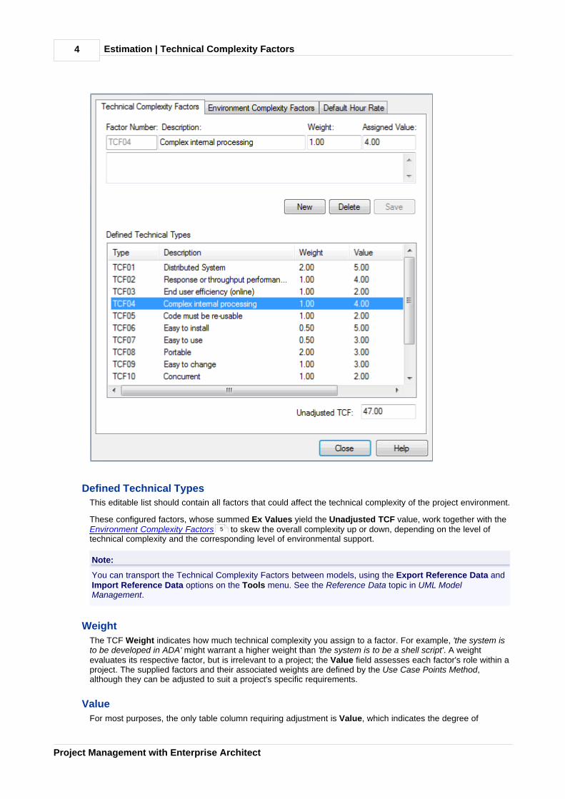
Technical Complexity Factors are used in the Use Case Metrics estimation technique. You can add or modifythese factors using the Estimation Factors dialog.
To open this dialog, select the Settings | Estimation Factors menu option. Click on the Technical ComplexityFactors tab.
3
5
8
6
Estimation | Technical Complexity Factors4
Project Management with Enterprise Architect
Defined Technical Types
This editable list should contain all factors that could affect the technical complexity of the project environment.
These configured factors, whose summed Ex Values yield the Unadjusted TCF value, work together with theEnvironment Complexity Factors to skew the overall complexity up or down, depending on the level oftechnical complexity and the corresponding level of environmental support.
Note:
You can transport the Technical Complexity Factors between models, using the Export Reference Data andImport Reference Data options on the Tools menu. See the Reference Data topic in UML ModelManagement.
Weight
The TCF Weight indicates how much technical complexity you assign to a factor. For example, 'the system isto be developed in ADA' might warrant a higher weight than 'the system is to be a shell script'. A weightevaluates its respective factor, but is irrelevant to a project; the Value field assesses each factor's role within aproject. The supplied factors and their associated weights are defined by the Use Case Points Method,although they can be adjusted to suit a project's specific requirements.
Value
For most purposes, the only table column requiring adjustment is Value, which indicates the degree of
5
Estimation | Technical Complexity Factors 5
© 1998-2010 Sparx Systems Pty Ltd
influence a particular factor has on the project. As a suggested gauge, a value of 0 indicates no influence, 3indicates average influence and 5 indicates strong influence.
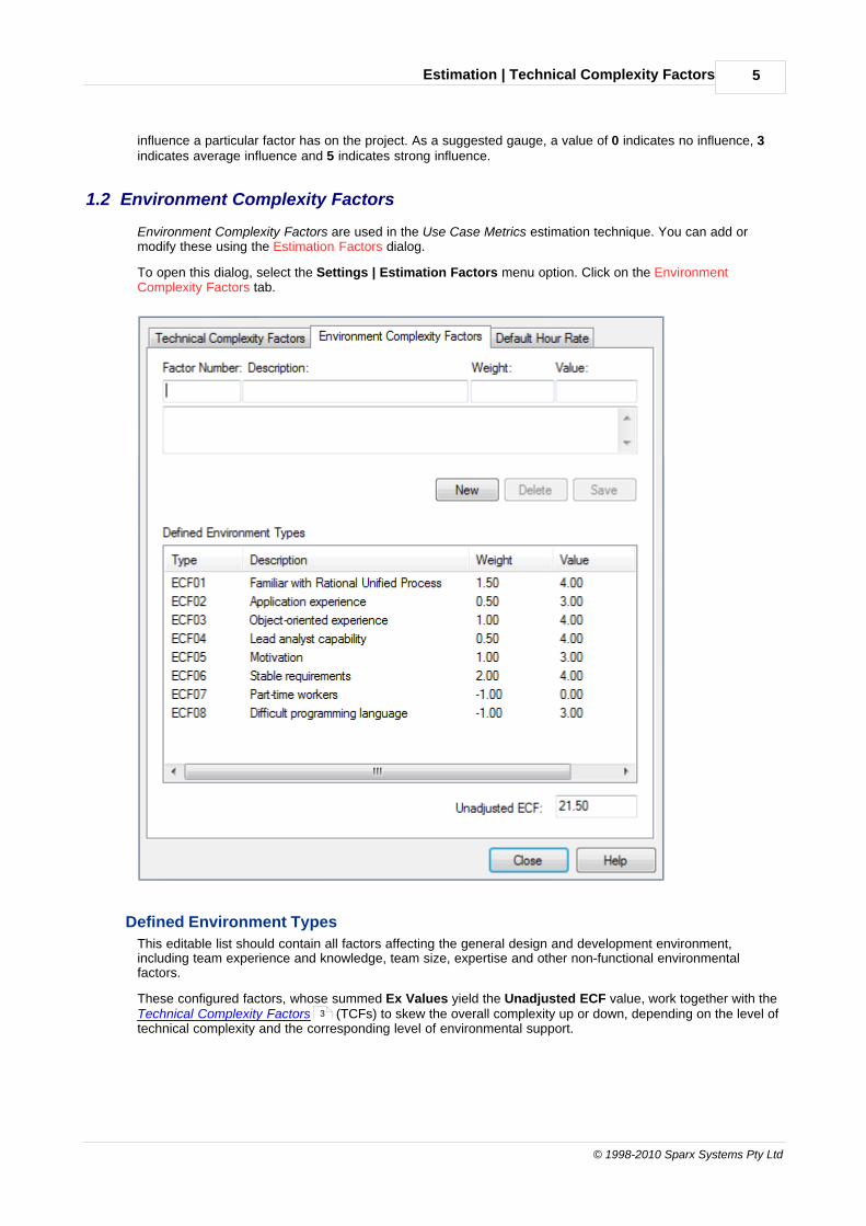
1.2 Environment Complexity Factors
Environment Complexity Factors are used in the Use Case Metrics estimation technique. You can add ormodify these using the Estimation Factors dialog.
To open this dialog, select the Settings | Estimation Factors menu option. Click on the EnvironmentComplexity Factors tab.
Defined Environment Types
This editable list should contain all factors affecting the general design and development environment,including team experience and knowledge, team size, expertise and other non-functional environmentalfactors.
These configured factors, whose summed Ex Values yield the Unadjusted ECF value, work together with theTechnical Complexity Factors (TCFs) to skew the overall complexity up or down, depending on the level oftechnical complexity and the corresponding level of environmental support.
3

Estimation | Environment Complexity Factors6
Project Management with Enterprise Architect
Note:
You can transport the Environment Complexity Factors between models, using the Export Reference Dataand Import Reference Data options on the Tools menu. See the Reference Data topic in UML ModelManagement.
Weight
A Weight evaluates its respective factor's complexity in comparison to other factors, but is irrelevant to aproject; the Value field assesses each factor's role within a project. The supplied factors and their associatedweights are defined by the Use Case Points Method, although they can be adjusted to suit a project's specificrequirements.
Value
For most purposes, the only table column requiring adjustment is Value, which indicates the degree ofinfluence a particular factor has over the project. As a suggested gauge, a value of 0 indicates no influence, 3indicates average influence and 5 indicates strong influence.
1.3 Estimating Project Size
Note:
This technique is of value only once you have developed a couple of known projects to use as a baseline.Please DO NOT use the provided 'guesstimates' as a real world measure until you have some real worldbase lines to measure against.
Enterprise Architect uses a simple estimation technique based on the number of Use Cases to be built, thedifficulty level of those Use Cases, some project environment factors and some build parameters. Once theparameters are set up and the Use Cases defined, open the Use Case Metrics dialog by:
· Navigating to the package of interest and selecting the Project | Use Case Metrics menu option, or
· Right-clicking on the package of interest in the Project Browser and selecting the Documentation |Package Metrics context menu option.

Estimation | Estimating Project Size 7
© 1998-2010 Sparx Systems Pty Ltd
Option Use to
Root Package Confirm the root package in the hierarchy. All Use Cases under here couldpotentially be included in the report.
Reload Re-run the search, usually after you change the filter criteria.
Phase like Include Use Cases with a phase that matches the wildcard value in the field (use * tomatch any characters, for example 1.* for 1.1 and 1.2).
Keyword like Include Use Cases with a keyword that matches the wildcard value in the field (use *to match any characters).
Use Cases Check the total count of Use Cases in estimate.
Technical ComplexityFactor
Review the parameters that describe the degree of technical complexity of theproject. While the unadjusted TCF value comes from theTechnical ComplexityFactor tab of the Metrics and Estimation Types dialog, the other values composethe Use Case Points Method formula. Modify these fields with caution. The finalproject estimate is directly proportional to the TCF.
EnvironmentComplexity Factor
Review the parameters that calculate the degree of environmental complexity of theproject, from factors such as programmer motivation or experience. The listedparameters compose the formula calculating the ECF, defined by the Use CasePoints Method; the only parameter affected by the project is the unadjusted ECFvalue, derived from the Environment Complexity Factors tab of the Metrics andEstimation Types dialog. The final project estimate is directly proportional to theECF.
Unadjusted UseCase Points (UUCP)
Check the sum of the Use Case complexity numbers.
Ave Hours per UseCase
Check the average of the number of hours assigned to easy, medium and difficultUse Cases; for information purposes only.
3
5
Estimation | Estimating Project Size8
Project Management with Enterprise Architect
Option Use to
Total Estimate Review the detailed breakdown of the final figure. Note that you must tailor the hoursper Use Case point figure to the level that matches your type of project andcapability based on known previous project outcomes.
Default Rate Set the default hours fed into the final calculation.
Re-Calculate Re-run the estimate, usually after you change the hours or Use Case point number.
Report Produce a rich text formatted report from the current estimate.
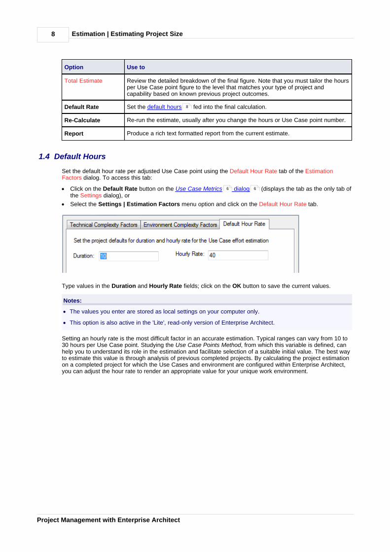
1.4 Default Hours
Set the default hour rate per adjusted Use Case point using the Default Hour Rate tab of the EstimationFactors dialog. To access this tab:
· Click on the Default Rate button on the Use Case Metrics dialog (displays the tab as the only tab ofthe Settings dialog), or
· Select the Settings | Estimation Factors menu option and click on the Default Hour Rate tab.
Type values in the Duration and Hourly Rate fields; click on the OK button to save the current values.
Notes:
· The values you enter are stored as local settings on your computer only.
· This option is also active in the 'Lite', read-only version of Enterprise Architect.
Setting an hourly rate is the most difficult factor in an accurate estimation. Typical ranges can vary from 10 to30 hours per Use Case point. Studying the Use Case Points Method, from which this variable is defined, canhelp you to understand its role in the estimation and facilitate selection of a suitable initial value. The best wayto estimate this value is through analysis of previous completed projects. By calculating the project estimationon a completed project for which the Use Cases and environment are configured within Enterprise Architect,you can adjust the hour rate to render an appropriate value for your unique work environment.
8
6 6
Resource Management | 9
© 1998-2010 Sparx Systems Pty Ltd
2 Resource Management
What is a Resource?
Resources are the people who work on a project. They can be assigned roles and allocated tasks, whichenables tracking of effort and estimation of time to complete.
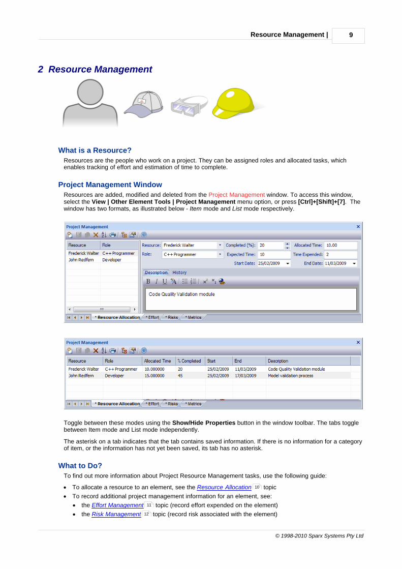
Project Management Window
Resources are added, modified and deleted from the Project Management window. To access this window,select the View | Other Element Tools | Project Management menu option, or press [Ctrl]+[Shift]+[7]. Thewindow has two formats, as illustrated below - Item mode and List mode respectively.
Toggle between these modes using the Show/Hide Properties button in the window toolbar. The tabs togglebetween Item mode and List mode independently.
The asterisk on a tab indicates that the tab contains saved information. If there is no information for a categoryof item, or the information has not yet been saved, its tab has no asterisk.
What to Do?
To find out more information about Project Resource Management tasks, use the following guide:
· To allocate a resource to an element, see the Resource Allocation topic
· To record additional project management information for an element, see:
· the Effort Management topic (record effort expended on the element)
· the Risk Management topic (record risk associated with the element)
10
11
12

Resource Management | 10
Project Management with Enterprise Architect
· the Metrics topic (record metrics measured for an element)
· To obtain a report of resource allocation details, see the Resource Report topic
· To configure Project Management data and populate the drop-down lists used on the Project Managementdialog tabs, see the following topics:
· Roles (see the Reference Data topic in UML Model Management)
· Clients (see the Reference Data topic in UML Model Management)
· Effort Types
· Metric Types
· Risk Types
· To find out about the functions of the Project Management toolbar, see the Project Management Windowtopic in Using Enterprise Architect - UML Modeling Tool.
Note:
In the Corporate, Business and Software Engineering, System Engineering and Ultimate editions ofEnterprise Architect, if security is enabled you must have Manage Project Information permission to updateand manage project resources, effort, metrics and risks. See User Security in UML Models.
2.1 Resource Allocation
Enterprise Architect enables you to connect a named resource in a named role to a given model element. Thisenables the Project Manager to track how far development of required components and Classes hasprogressed (provided the team members keep their figures up to date).
To enter resource allocation details for an element, follow the steps below:
1. Select the element in the Project Browser.
2. Select the View | Other Element Tools | Project Management menu option. The Project Managementwindow displays, showing the Resource Allocation tab.
3. Click on the New icon on the Project Management window toolbar.
The Resource Allocation tab enables you to enter the following data:
· The name of the resource (click on the drop-down arrow and select, or type the name in)
· The role of the resource (click on the drop-down arrow and select, or type the name in)
· The start and end date for the availability of the resource
· The time allocated to the resource
· The percentage of the task the resource has completed
· The expected time allocated to the resource
· The actual time expended by the resource
· A description of the work being done by the resource (this text is also displayed in the Notes window; itcannot be edited in that window)
· Notes on the activity history of the resource (this text is also displayed in the Notes window; it cannot beedited in that window).
13
14
15
16
17
Resource Management | Resource Allocation 11
© 1998-2010 Sparx Systems Pty Ltd
For information on the Notes window, see Using Enterprise Architect - UML Modeling Tool.
To edit existing Resource Allocation items for this element, click on the required item in the:
· list panel to the left of the window, in Item mode
· list, in List mode, or
· Project Management folder in the Element Browser window (see Using Enterprise Architect - UML
Modeling Tool); if this window is not displayed, click on the icon in the Project Management windowtoolbar. Resource Allocation item icons have an R in the bottom right corner.
To change the element to which to allocate resources, select the required element in the Project Browser.
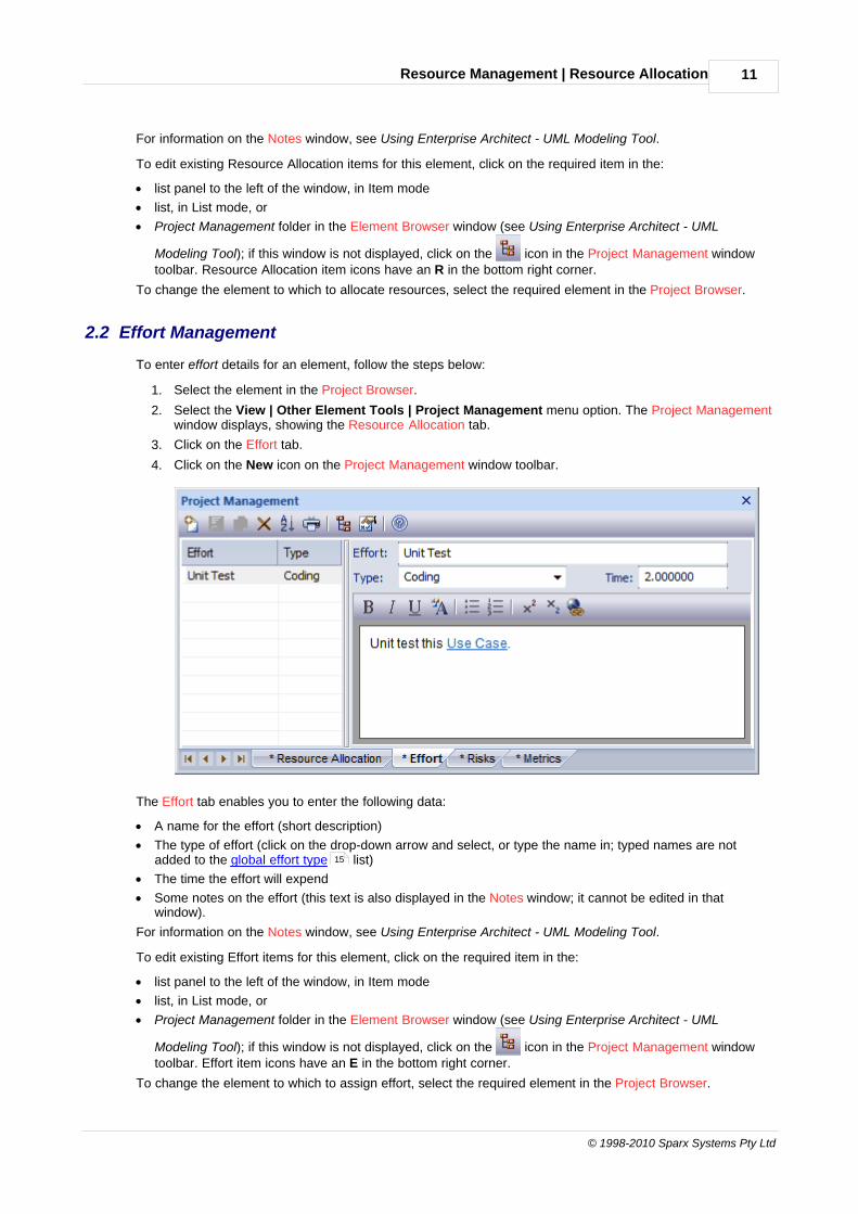
2.2 Effort Management
To enter effort details for an element, follow the steps below:
1. Select the element in the Project Browser.
2. Select the View | Other Element Tools | Project Management menu option. The Project Managementwindow displays, showing the Resource Allocation tab.
3. Click on the Effort tab.
4. Click on the New icon on the Project Management window toolbar.
The Effort tab enables you to enter the following data:
· A name for the effort (short description)
· The type of effort (click on the drop-down arrow and select, or type the name in; typed names are notadded to the global effort type list)
· The time the effort will expend
· Some notes on the effort (this text is also displayed in the Notes window; it cannot be edited in thatwindow).
For information on the Notes window, see Using Enterprise Architect - UML Modeling Tool.
To edit existing Effort items for this element, click on the required item in the:
· list panel to the left of the window, in Item mode
· list, in List mode, or
· Project Management folder in the Element Browser window (see Using Enterprise Architect - UML
Modeling Tool); if this window is not displayed, click on the icon in the Project Management windowtoolbar. Effort item icons have an E in the bottom right corner.
To change the element to which to assign effort, select the required element in the Project Browser.
15
Resource Management | Effort Management12
Project Management with Enterprise Architect
Notes:
· The drop-down arrow on the Type field displays a list of effort types as defined on the Effort tab of theMetric and Estimation Types dialog. If required, you can type in alternative effort types, but these are notadded to the drop-down list of defined types.
· Although Enterprise Architect does not currently provide detailed reports on effort within a model, you canuse the Automation Interface or similar tools to create your own custom reports based on effort informationyou enter; see the Enterprise Architect Object Model topic in SDK for Enterprise Architect.
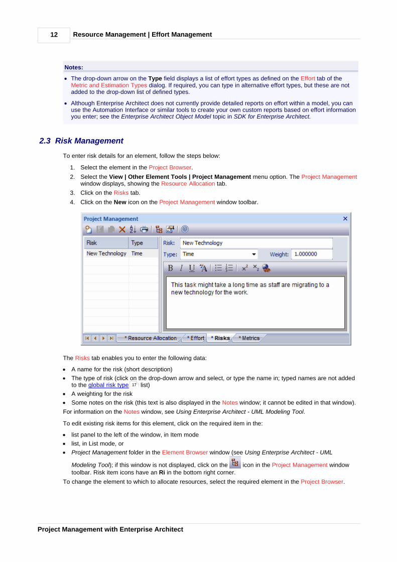
2.3 Risk Management
To enter risk details for an element, follow the steps below:
1. Select the element in the Project Browser.
2. Select the View | Other Element Tools | Project Management menu option. The Project Managementwindow displays, showing the Resource Allocation tab.
3. Click on the Risks tab.
4. Click on the New icon on the Project Management window toolbar.
The Risks tab enables you to enter the following data:
· A name for the risk (short description)
· The type of risk (click on the drop-down arrow and select, or type the name in; typed names are not addedto the global risk type list)
· A weighting for the risk
· Some notes on the risk (this text is also displayed in the Notes window; it cannot be edited in that window).
For information on the Notes window, see Using Enterprise Architect - UML Modeling Tool.
To edit existing risk items for this element, click on the required item in the:
· list panel to the left of the window, in Item mode
· list, in List mode, or
· Project Management folder in the Element Browser window (see Using Enterprise Architect - UML
Modeling Tool); if this window is not displayed, click on the icon in the Project Management windowtoolbar. Risk item icons have an Ri in the bottom right corner.
To change the element to which to allocate resources, select the required element in the Project Browser.
17
Resource Management | Risk Management 13
© 1998-2010 Sparx Systems Pty Ltd
Note:
Although Enterprise Architect does not currently provide detailed reports on risks within a model, you can usethe Automation Interface or similar tools to create your own custom reports based on risk information youenter; see the Enterprise Architect Object Model topic in SDK for Enterprise Architect.
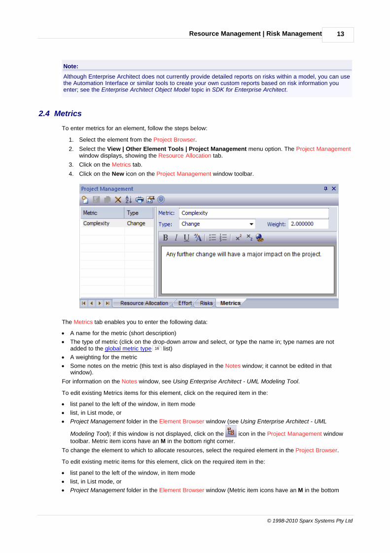
2.4 Metrics
To enter metrics for an element, follow the steps below:
1. Select the element from the Project Browser.
2. Select the View | Other Element Tools | Project Management menu option. The Project Managementwindow displays, showing the Resource Allocation tab.
3. Click on the Metrics tab.
4. Click on the New icon on the Project Management window toolbar.
The Metrics tab enables you to enter the following data:
· A name for the metric (short description)
· The type of metric (click on the drop-down arrow and select, or type the name in; type names are notadded to the global metric type list)
· A weighting for the metric
· Some notes on the metric (this text is also displayed in the Notes window; it cannot be edited in thatwindow).
For information on the Notes window, see Using Enterprise Architect - UML Modeling Tool.
To edit existing Metrics items for this element, click on the required item in the:
· list panel to the left of the window, in Item mode
· list, in List mode, or
· Project Management folder in the Element Browser window (see Using Enterprise Architect - UML
Modeling Tool); if this window is not displayed, click on the icon in the Project Management windowtoolbar. Metric item icons have an M in the bottom right corner.
To change the element to which to allocate resources, select the required element in the Project Browser.
To edit existing metric items for this element, click on the required item in the:
· list panel to the left of the window, in Item mode
· list, in List mode, or
· Project Management folder in the Element Browser window (Metric item icons have an M in the bottom
16

Resource Management | Metrics14
Project Management with Enterprise Architect
right corner). If this window is not displayed, click on the icon in the Project Management windowtoolbar.
To change the element to which to assign metrics, select the required element in the Project Browser.
Note:
Although Enterprise Architect does not currently provide detailed reports on metrics within a model, you canuse the Automation Interface or similar tools to create your own custom reports based on metric informationyou enter; see the Enterprise Architect Object Model topic in SDK for Enterprise Architect.
2.5 Resource Report
To generate a resource report on a package, either:
· In the Project Browser, right-click on the package to create a report for and, from the context menu, selectthe Documentation | Resource Allocation option, or
· If the diagram currently active belongs to the package to create a report for, select the Project |Documentation | Resource and Tasking Details menu option.
The Resource and Tasking Details dialog displays a list of all elements that have resources allocated to them.The result list includes the resource allocated, the start and end dates, the percentage complete and otherrelevant information. You can print out the results if required.
Option Use to
Root Package Confirm the name of the root package for which resourcing is being determined.
Resource Change the (optional) name of a specific resource assigned to the project.
As At Date Select the date to run the resource report for.
Cut Off Set the percentage complete limit to include or exclude resource details; see ShowWhere.

Resource Management | Resource Report 15
© 1998-2010 Sparx Systems Pty Ltd
Option Use to
Show Where Show resourcing where percentage complete is Complete, Above the cut-off,Below the cut-off, or any of these three.
Refresh Refresh the form.
Locate Object (Click on an entry in the report.) Find the selected element from the results list inthe Project Browser.
Print Print the report.
Resourcing Details Review the list of resources that meet the search criteria.
2.6 Effort Types
You can specify the effort types used when assigning effort to an element in Enterprise Architect, using theEffort tab of the Project Indicators dialog. Creating an effort type using this dialog adds to a global list of efforttypes that can be added to any element in the model. This list of types displays in the Type field drop-down liston the Effort tab of the Project Management window.
To open the Project Indicators dialog, select the Settings | Project Indicators menu option. Click on the Efforttab.
2

Resource Management | Effort Types16
Project Management with Enterprise Architect
To create a new effort type, click on the New button, or to edit an existing effort type, click on the effort typename in the Defined Effort Types list. Complete the fields as follows:
· In the Effort field type the name of the effort type
· In the Description field type a short description of the effort type
· In the Weight field type the weighting to apply to the effort type
· In the Note field, type any additional information on the effort type
· Click on the Save button.
Notes:
· Although Enterprise Architect does not currently provide detailed reports on effort within a model, you canuse the Automation Interface or similar tools to create your own custom reports based on effort informationyou enter; see the Enterprise Architect Object Model topic in SDK for Enterprise Architect.
· You can transport effort types between models, using the Export Reference Data and Import ReferenceData options on the Tools menu; see the Reference Data topic in UML Model Management.
2.7 Metric Types
You can specify the metric types used when assigning metrics to an element in Enterprise Architect, using theMetric tab of the Project Indicators dialog. Creating a metric using this dialog creates a global list of metricsthat can be added to any element in the model. You can define a metric on other screens, such as the Metrics
tab of the Project Management window, but such metrics are not added to the global list.
Select the Settings | Project Indicators menu option. On the Project Indicators dialog, click on the Metric tab.
13

Resource Management | Metric Types 17
© 1998-2010 Sparx Systems Pty Ltd
To create a new metric type, click on the New button, or to edit an existing metric type, click on the metric typename in the Defined Metrics list. Complete the fields as follows:
· In the Metric Type field type the name of the metric type
· In the Description field type a short description of the metric type
· In the Weight field type the weighting to apply to the metric type
· In the Note field, type any additional information on the metric type
· Click on the Save button.
Notes:
· Although Enterprise Architect does not currently provide detailed reports on metrics within a model, youcan use the Automation Interface or similar tools to create your own custom reports based on metricsinformation you enter; see the Enterprise Architect Object Model topic in SDK for Enterprise Architect.
· You can transport metric types between models, using the Export Reference Data and Import ReferenceData options on the Tools menu; see the Reference Data topic in UML Model Management.
2.8 Risk Types
You can specify the risk types used when assigning risk to an element in Enterprise Architect, using the Risktab of the Project Indicators dialog. Creating a risk type using this dialog creates a global list of risk types thatcan be added to any element in the model. You can define a risk type on other screens, such as the Riskstab of the Project Management window, but such risks are not added to the global list.
12

Resource Management | Risk Types18
Project Management with Enterprise Architect
Select the Settings | Project Indicators menu option. On the Project Indicators dialog, click on the Risk tab.
To create a new risk type, click on the New button, or to edit an existing risk type, click on the risk type namein the Defined Risks list. Complete the fields as follows:
· In the Risk Type field type the name of the risk type
· In the Description field type a short description of the risk type
· In the Weight field type the weighting to apply to the risk type
· In the Note field, type any additional information on the risk type
· Click on the Save button.
Notes:
· Although Enterprise Architect does not currently provide detailed reports on risks within a model, you canuse the Automation Interface or similar tools to create your own custom reports based on risk informationyou enter; see the Enterprise Architect Object Model topic in SDK for Enterprise Architect.
· You can transport risk types between models, using the Export Reference Data and Import ReferenceData options on the Tools menu; see the Reference Data topic in UML Model Management.
Testing | 19
© 1998-2010 Sparx Systems Pty Ltd
3 Testing
Introduction to Testing
In addition to the integrated JUnit and NUnit testing capabilities (see the Unit Testing topic in Visual ExecutionAnalyzer in Enterprise Architect), Enterprise Architect enables you to attach arbitrarily complex tests to anymodel element. Keeping the model elements and the testing documentation in one integrated modelsignificantly improves the communication between the test-team and the software developers and architects.The detailed search facilities make it easy to find failing test cases, test cases not run and tests cases thathave been passed. Using the testing and search capabilities, it is easy to navigate through the model andquickly locate problem spots, design flaws and other critical issues. Enterprise Architect is not only a UMLModeling environment, it is also a complete Test Management environment.
Basic Tasks
Simple tasks that you might perform include:
· Open the Testing Workspace
· Use the Test Details Dialog .
Categories
Typically you create:
· Unit tests for things that are being built, such as Classes and components
· Integration tests to test how components work together
· System tests to ensure the system meets business requirements
· Acceptance tests to test user satisfaction, and
· Scenario tests to test the end-to-end suitability and functionality of the application.
Using Tests
Other tasks that you might perform when working with tests include:
· Import a Scenario as a Test
· Move or Copy Tests Between Test Types
· Import a Test from Other Elements
· Import a Responsibility or Constraint as a Test
· Create a Maintenance Item from a Test
· Generate Test Details Report
· Show Test Script Compartments
· Create Test Documentation .
Note:
Most of the tasks identified above relate to a tests for a single element. You can make a set of tests availableto a number of elements by performing the above tasks on a Test Case element and then associating thatTest Case with each of the other elements. The Test Case element also helps to make tests more visible indiagrams, the Project Browser, windows and searches. See the UML Elements topic in the UML Dictionary.
20
21
22
23
24
25
26
27
27
29
30
31
32
32
33
Testing | The Testing Workspace20
Project Management with Enterprise Architect
3.1 The Testing Workspace
The Testing window, or Workspace, provides a quick and convenient method of working with element tests.When you select an element in a diagram or in the Project Browser, if the Testing window is visible the lists oftests for that element are loaded ready for modification or addition.
Note:
In the Corporate, Business and Software Engineering, System Engineering and Ultimate editions ofEnterprise Architect, if security is enabled you must have Manage Tests permission to update and delete testrecords. See User Security in UML Models.
To open the Testing window, select the View | Testing menu option. Alternatively, press [Alt]+[3]. Thewindow can be docked to the application workspace.
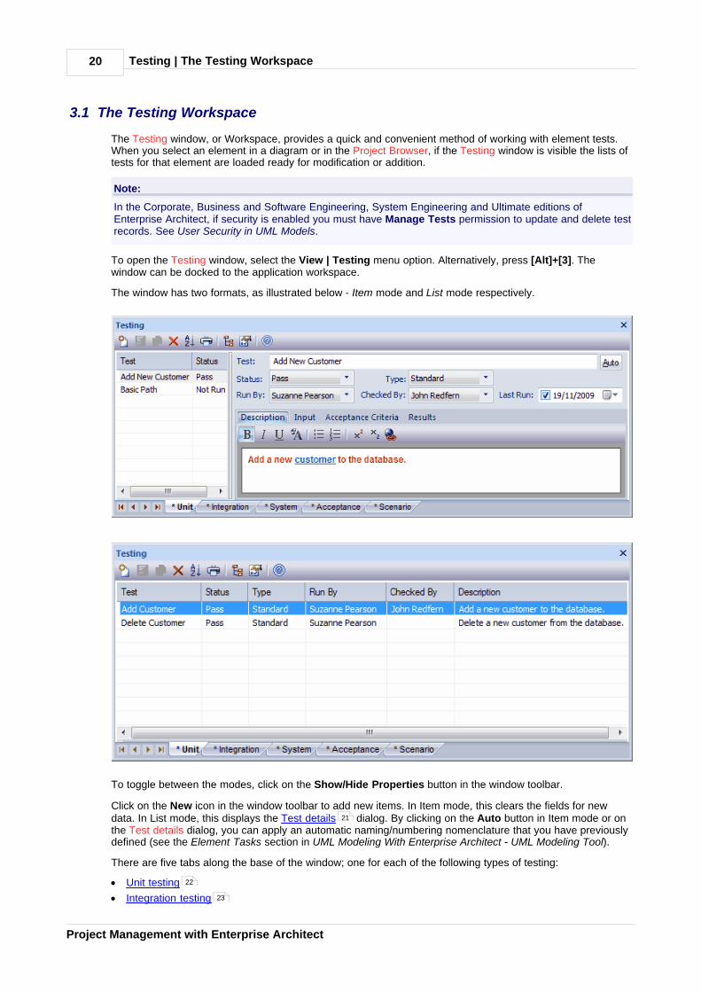
The window has two formats, as illustrated below - Item mode and List mode respectively.
To toggle between the modes, click on the Show/Hide Properties button in the window toolbar.
Click on the New icon in the window toolbar to add new items. In Item mode, this clears the fields for newdata. In List mode, this displays the Test details dialog. By clicking on the Auto button in Item mode or onthe Test details dialog, you can apply an automatic naming/numbering nomenclature that you have previouslydefined (see the Element Tasks section in UML Modeling With Enterprise Architect - UML Modeling Tool).
There are five tabs along the base of the window; one for each of the following types of testing:
· Unit testing
· Integration testing
21
22
23
Testing | The Testing Workspace 21
© 1998-2010 Sparx Systems Pty Ltd
· System testing
· Acceptance testing
· Scenario testing
The asterisk on a tab indicates that the tab contains saved information. If there is no information for a type oftest, or the information has not yet been saved, its tab has no asterisk.
The tabs toggle between Item mode and List mode independently.
3.2 The Test Details Dialog
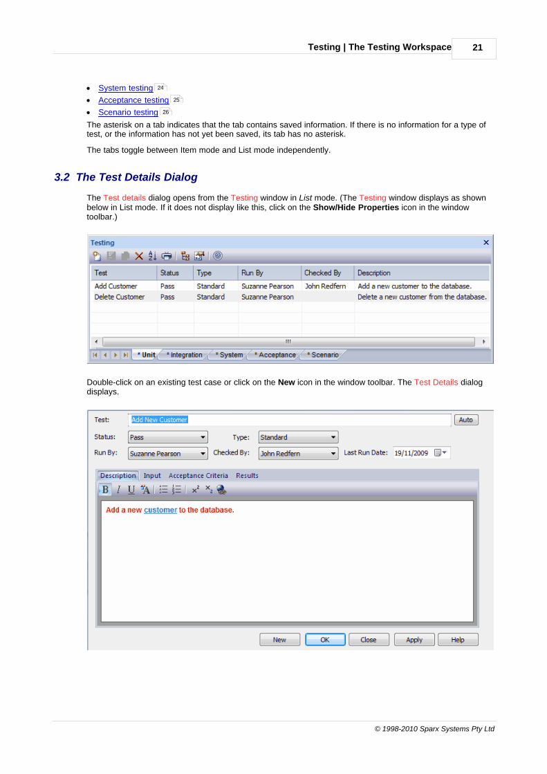
The Test details dialog opens from the Testing window in List mode. (The Testing window displays as shownbelow in List mode. If it does not display like this, click on the Show/Hide Properties icon in the windowtoolbar.)
Double-click on an existing test case or click on the New icon in the window toolbar. The Test Details dialogdisplays.
24
25
26
Testing | The Test Details Dialog22
Project Management with Enterprise Architect
Notes:
· Add multiple test cases in one batch by using the New and Apply buttons.
· You can format the text in the Description, Input, Acceptance Criteria and Results tabs using the Rich TextNotes toolbar at the top of the field (see the Workspace Toolbars topic in Using Enterprise Architect - UMLModeling Tool). This text is also reflected in the Notes window, but cannot be edited there.
3.3 Unit Testing
Use Unit Testing to test Classes, Components and other elements as programmers build them.
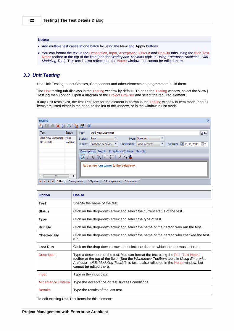
The Unit testing tab displays in the Testing window by default. To open the Testing window, select the View |Testing menu option. Open a diagram or the Project Browser and select the required element.
If any Unit tests exist, the first Test item for the element is shown in the Testing window in Item mode, and allitems are listed either in the panel to the left of the window, or in the window in List mode.
Option Use to
Test Specify the name of the test.
Status Click on the drop-down arrow and select the current status of the test.
Type Click on the drop-down arrow and select the type of test.
Run By Click on the drop-down arrow and select the name of the person who ran the test.
Checked By Click on the drop-down arrow and select the name of the person who checked the testrun.
Last Run Click on the drop-down arrow and select the date on which the test was last run.
Description Type a description of the test. You can format the text using the Rich Text Notestoolbar at the top of the field. (See the Workspace Toolbars topic in Using EnterpriseArchitect - UML Modeling Tool.) This text is also reflected in the Notes window, butcannot be edited there.
Input Type in the input data.
Acceptance Criteria Type the acceptance or test success conditions.
Results Type the results of the last test.
To edit existing Unit Test items for this element:

Testing | Unit Testing 23
© 1998-2010 Sparx Systems Pty Ltd
· Click on the item in the left-hand panel in Item mode
· Double-click on the item in List mode to display the Test Details dialog, or
· Click on the required item in the Testing folder in the Element Browser window (see Using Enterprise
Architect - UML Modeling Tool); if this window is not displayed, click on the icon in the Testing windowtoolbar. Unit Test item icons have a U in the bottom right corner.
To change the element for which to create test items, click on the required element in the Project Browser.
3.4 Integration Testing
Use Integration Testing to test how the constructed components work together.
To display Integration Testing details select the View | Testing menu option to display the Testing window.Open a diagram or the Project Browser and select the required element. Click on the Integration tab.
If any Integration tests exist, the first Test item for the element is shown in the Testing window in Item mode,and all items are listed either in the panel to the left of the window, or in the window in List mode.
Option Use to
Test Specify the name of the test.
Status Click on the drop-down arrow and select the current status of the test.
Type Click on the drop-down arrow and select the type of test.
Run By Click on the drop-down arrow and select the name of the person who ran the test.
Checked By Click on the drop-down arrow and select the name of the person who checked the testrun.
Last Run Click on the drop-down arrow and select the date on which the test was last run.
Description Type a description of the test. You can format the text using the Rich Text Notestoolbar at the top of the field. (See the Workspace Toolbars topic in Using EnterpriseArchitect - UML Modeling Tool.) This text is also reflected in the Notes window, butcannot be edited there.
Input Type in the input data.
AcceptanceCriteria
Type the acceptance or test success conditions.
Results Type the results of the last test.
To edit existing Integration Test items for this element:
21
Testing | Integration Testing24
Project Management with Enterprise Architect
· Click on the item in the left-hand panel in Item mode
· Double-click on the item in List mode to display the Test Details dialog, or
· Click on the required item in the Testing folder in the Element Browser window (see Using Enterprise
Architect - UML Modeling Tool); if this window is not displayed, click on the icon in the Testing windowtoolbar. Integration Test item icons have an I in the bottom right corner.
To change the element for which to create test items, click on the required element in the Project Browser.
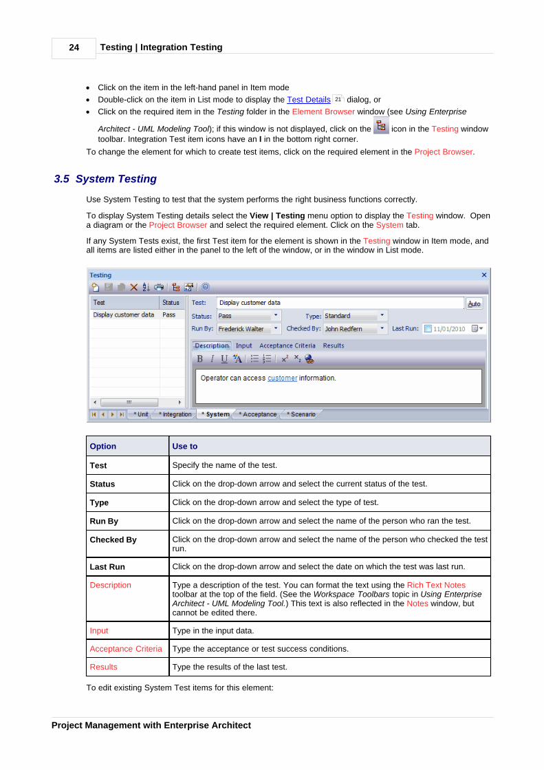
3.5 System Testing
Use System Testing to test that the system performs the right business functions correctly.
To display System Testing details select the View | Testing menu option to display the Testing window. Opena diagram or the Project Browser and select the required element. Click on the System tab.
If any System Tests exist, the first Test item for the element is shown in the Testing window in Item mode, andall items are listed either in the panel to the left of the window, or in the window in List mode.
Option Use to
Test Specify the name of the test.
Status Click on the drop-down arrow and select the current status of the test.
Type Click on the drop-down arrow and select the type of test.
Run By Click on the drop-down arrow and select the name of the person who ran the test.
Checked By Click on the drop-down arrow and select the name of the person who checked the testrun.
Last Run Click on the drop-down arrow and select the date on which the test was last run.
Description Type a description of the test. You can format the text using the Rich Text Notestoolbar at the top of the field. (See the Workspace Toolbars topic in Using EnterpriseArchitect - UML Modeling Tool.) This text is also reflected in the Notes window, butcannot be edited there.
Input Type in the input data.
Acceptance Criteria Type the acceptance or test success conditions.
Results Type the results of the last test.
To edit existing System Test items for this element:
21
Testing | System Testing 25
© 1998-2010 Sparx Systems Pty Ltd
· Click on the item in the left-hand panel in Item mode
· Double-click on the item in List mode to display the Test Details dialog, or
· Click on the required item in the Testing folder in the Element Browser window (see Using Enterprise
Architect - UML Modeling Tool); if this window is not displayed, click on the icon in the Testing windowtoolbar. System Test item icons have an Sy in the bottom right corner.
To change the element for which to create test items, click on the required element in the Project Browser.
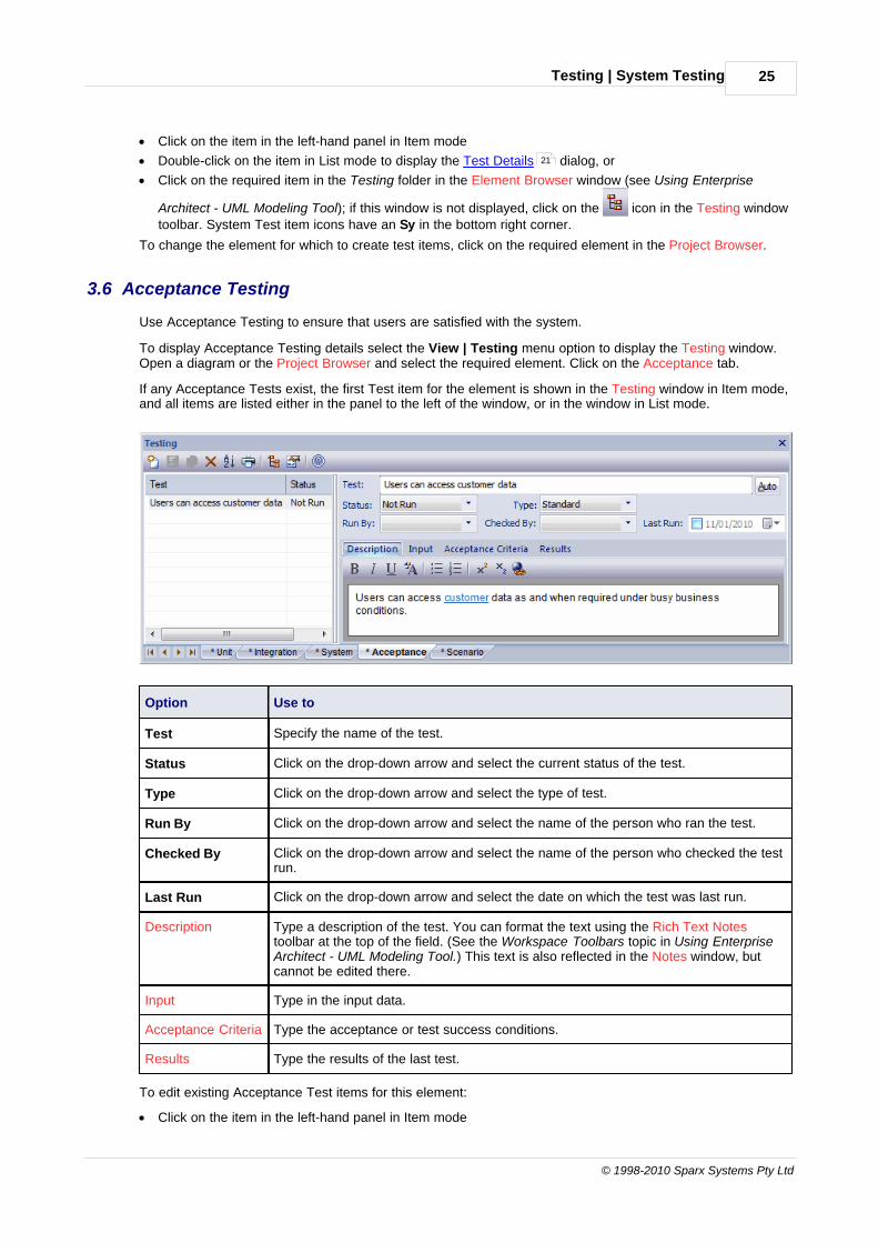
3.6 Acceptance Testing
Use Acceptance Testing to ensure that users are satisfied with the system.
To display Acceptance Testing details select the View | Testing menu option to display the Testing window.Open a diagram or the Project Browser and select the required element. Click on the Acceptance tab.
If any Acceptance Tests exist, the first Test item for the element is shown in the Testing window in Item mode,and all items are listed either in the panel to the left of the window, or in the window in List mode.
Option Use to
Test Specify the name of the test.
Status Click on the drop-down arrow and select the current status of the test.
Type Click on the drop-down arrow and select the type of test.
Run By Click on the drop-down arrow and select the name of the person who ran the test.
Checked By Click on the drop-down arrow and select the name of the person who checked the testrun.
Last Run Click on the drop-down arrow and select the date on which the test was last run.
Description Type a description of the test. You can format the text using the Rich Text Notestoolbar at the top of the field. (See the Workspace Toolbars topic in Using EnterpriseArchitect - UML Modeling Tool.) This text is also reflected in the Notes window, butcannot be edited there.
Input Type in the input data.
Acceptance Criteria Type the acceptance or test success conditions.
Results Type the results of the last test.
To edit existing Acceptance Test items for this element:
· Click on the item in the left-hand panel in Item mode
21

Testing | Acceptance Testing26
Project Management with Enterprise Architect
· Double-click on the item in List mode to display the Test Details dialog, or
· Click on the required item in the Testing folder in the Element Browser window (see Using Enterprise
Architect - UML Modeling Tool); if this window is not displayed, click on the icon in the Testing windowtoolbar. Acceptance Test item icons have an A in the bottom right corner.
To change the element for which to create test items, click on the required element in the Project Browser.
3.7 Scenario Testing
Use Scenario Testing to test the application with real-world situations and scenarios. An end-to-end test of allfunctions.
To display Scenario Testing details select the View | Testing menu option to display the Testing window.Open a diagram or the Project Browser and select the required element. Click on the Scenario tab.
If any Scenario Tests exist, the first Test item for the element is shown in the Testing window in Item mode,and all items are listed either in the panel to the left of the window, or in the window in List mode.
Option Use to
Test Specify the name of the test.
Status Click on the drop-down arrow and select the current status of the test.
Type Click on the drop-down arrow and select the type of test.
Run By Click on the drop-down arrow and select the name of the person who ran the test.
Checked By Click on the drop-down arrow and select the name of the person who checked the testrun.
Last Run Click on the drop-down arrow and select the date on which the test was last run.
Description Type a description of the test. You can format the text using the Rich Text Notestoolbar at the top of the field. (See the Workspace Toolbars topic in Using EnterpriseArchitect - UML Modeling Tool.) This text is also reflected in the Notes window, butcannot be edited there.
Input Type in the input data.
AcceptanceCriteria
Type the acceptance or test success conditions.
Results Type the results of the last test.
To edit existing Scenario Test items for this element:
21

Testing | Scenario Testing 27
© 1998-2010 Sparx Systems Pty Ltd
· Click on the item in the left-hand panel in Item mode
· Double-click on the item in List mode to display the Test Details dialog, or
· Click on the required item in the Testing folder in the Element Browser window (see Using Enterprise
Architect - UML Modeling Tool); if this window is not displayed, click on the icon in the Testing windowtoolbar. Scenario Test item icons have an Sc in the bottom right corner.
To change the element for which to create test items, click on the required element in the Project Browser.
3.8 Move or Copy Tests Between Categories
When you define a test on the Unit, Integration, System, Acceptance or Scenario tab of the Testing window,you might decide that the test either is better suited to another category of tests, or forms a good template fortests in other categories. Enterprise Architect enables you to move or copy tests between categories.
To move or copy a test, follow the steps below:
1. Open either:
· The Testing window, and the tab that contains the test you want to move or copy, or
· The Testing folder of the Element Browser window (see Using Enterprise Architect - UML ModelingTool).
2. Right-click on the required test item in the list. The item context menu displays.
3. Click on the appropriate option - Move to or Copy to. A list of test categories displays.
4. Click on the test category to which to move or copy the test. A confirmatory prompt displays.
Note:
If you move or copy a test into the Scenario category, some unassociated data could be lost.
5. Click on the Yes button to confirm the move or copy.
6. Click on the target tab of the Testing window to ensure that the test has been added, and make anyrequired changes.
3.9 Import Scenario as Test
You can import a scenario from a Use Case or other element, or from all elements in a package, into the Testing window Scenario tab. This avoids having to duplicate the scenario information manually.
The scenario description is copied to the Scenario Test Description tab in the Testing window. If a scenariocontains a Structured Specification, its Action steps are also copied to the Description tab under the headingStructured Specification.
Import Element Scenarios
To import one or more scenarios from a specific element, follow the steps below:
1. Open a diagram or the Project Browser and select the element into which to import the scenario.
2. Open either:
· The Testing window and the Scenario tab, or
· The Testing folder of the Element Browser window (see Using Enterprise Architect - UML ModelingTool).
3. Right-click on the list of tests to display the context menu, and select the Import element scenario(s)menu option. The Import Scenario dialog displays.
21
Testing | Import Scenario as Test28
Project Management with Enterprise Architect
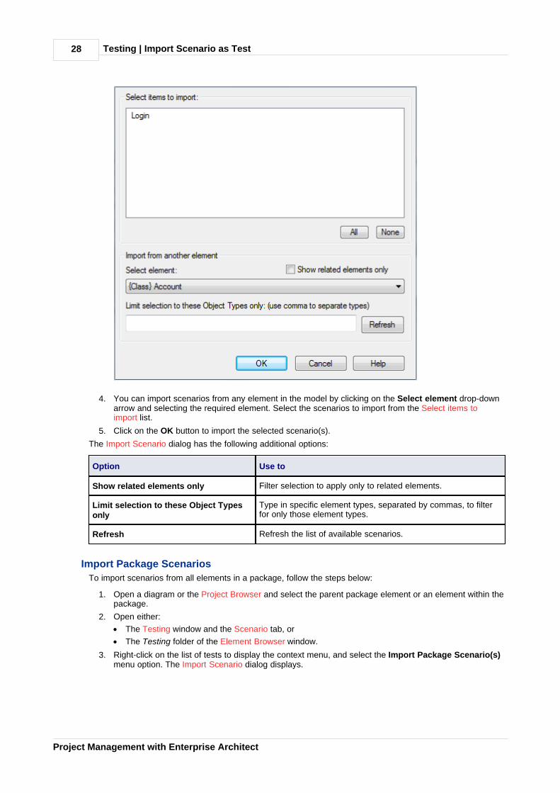
4. You can import scenarios from any element in the model by clicking on the Select element drop-downarrow and selecting the required element. Select the scenarios to import from the Select items toimport list.
5. Click on the OK button to import the selected scenario(s).
The Import Scenario dialog has the following additional options:
Option Use to
Show related elements only Filter selection to apply only to related elements.
Limit selection to these Object Typesonly
Type in specific element types, separated by commas, to filterfor only those element types.
Refresh Refresh the list of available scenarios.
Import Package Scenarios
To import scenarios from all elements in a package, follow the steps below:
1. Open a diagram or the Project Browser and select the parent package element or an element within thepackage.
2. Open either:
· The Testing window and the Scenario tab, or
· The Testing folder of the Element Browser window.
3. Right-click on the list of tests to display the context menu, and select the Import Package Scenario(s)menu option. The Import Scenario dialog displays.
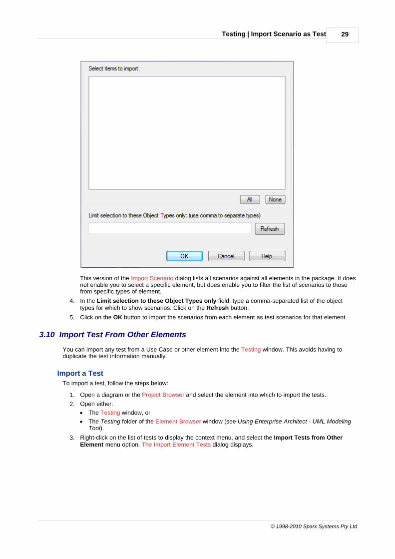
Testing | Import Scenario as Test 29
© 1998-2010 Sparx Systems Pty Ltd
This version of the Import Scenario dialog lists all scenarios against all elements in the package. It doesnot enable you to select a specific element, but does enable you to filter the list of scenarios to thosefrom specific types of element.
4. In the Limit selection to these Object Types only field, type a comma-separated list of the objecttypes for which to show scenarios. Click on the Refresh button.
5. Click on the OK button to import the scenarios from each element as test scenarios for that element.
3.10 Import Test From Other Elements
You can import any test from a Use Case or other element into the Testing window. This avoids having toduplicate the test information manually.
Import a Test
To import a test, follow the steps below:
1. Open a diagram or the Project Browser and select the element into which to import the tests.
2. Open either:
· The Testing window, or
· The Testing folder of the Element Browser window (see Using Enterprise Architect - UML ModelingTool).
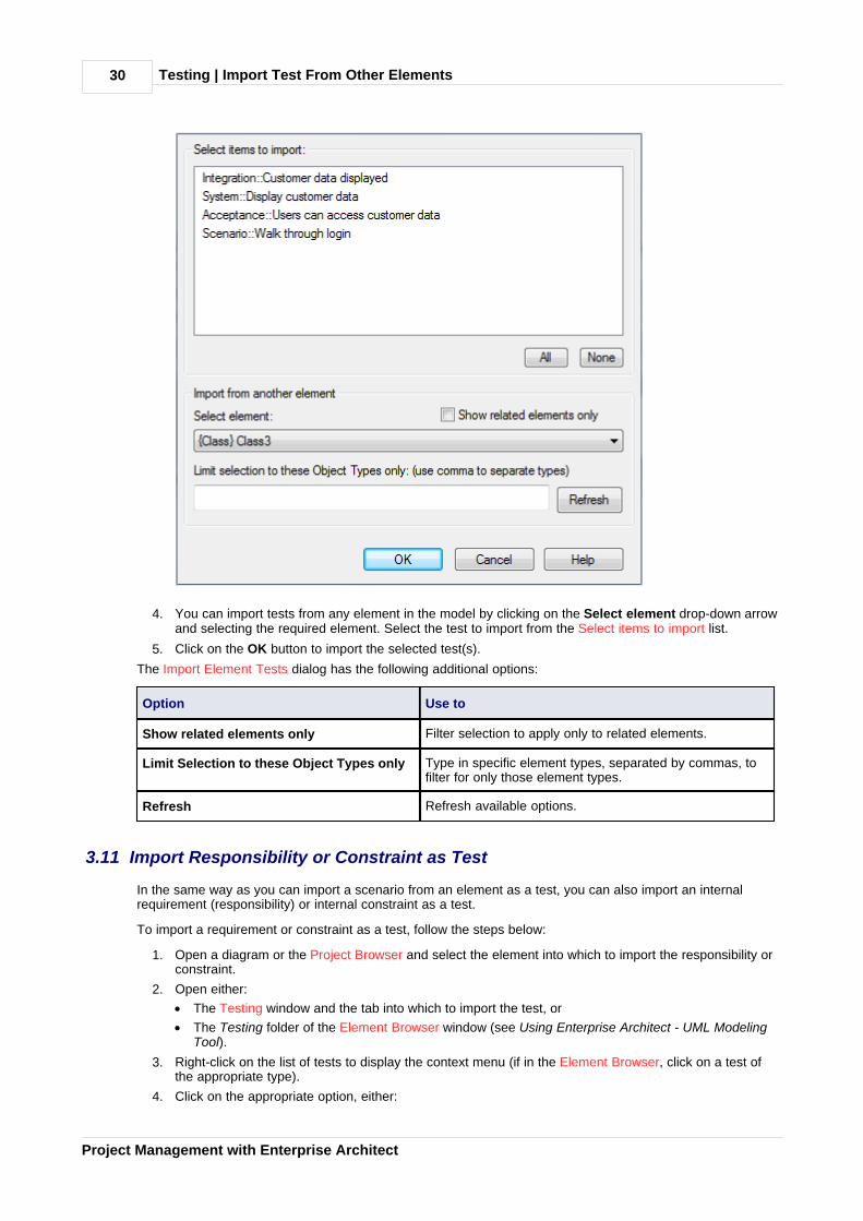
3. Right-click on the list of tests to display the context menu, and select the Import Tests from OtherElement menu option. The Import Element Tests dialog displays.
Testing | Import Test From Other Elements30
Project Management with Enterprise Architect
4. You can import tests from any element in the model by clicking on the Select element drop-down arrowand selecting the required element. Select the test to import from the Select items to import list.
5. Click on the OK button to import the selected test(s).
The Import Element Tests dialog has the following additional options:
Option Use to
Show related elements only Filter selection to apply only to related elements.
Limit Selection to these Object Types only Type in specific element types, separated by commas, tofilter for only those element types.
Refresh Refresh available options.
3.11 Import Responsibility or Constraint as Test
In the same way as you can import a scenario from an element as a test, you can also import an internalrequirement (responsibility) or internal constraint as a test.
To import a requirement or constraint as a test, follow the steps below:
1. Open a diagram or the Project Browser and select the element into which to import the responsibility orconstraint.
2. Open either:
· The Testing window and the tab into which to import the test, or
· The Testing folder of the Element Browser window (see Using Enterprise Architect - UML ModelingTool).
3. Right-click on the list of tests to display the context menu (if in the Element Browser, click on a test ofthe appropriate type).
4. Click on the appropriate option, either:
Testing | Import Responsibility or Constraint as Test 31
© 1998-2010 Sparx Systems Pty Ltd
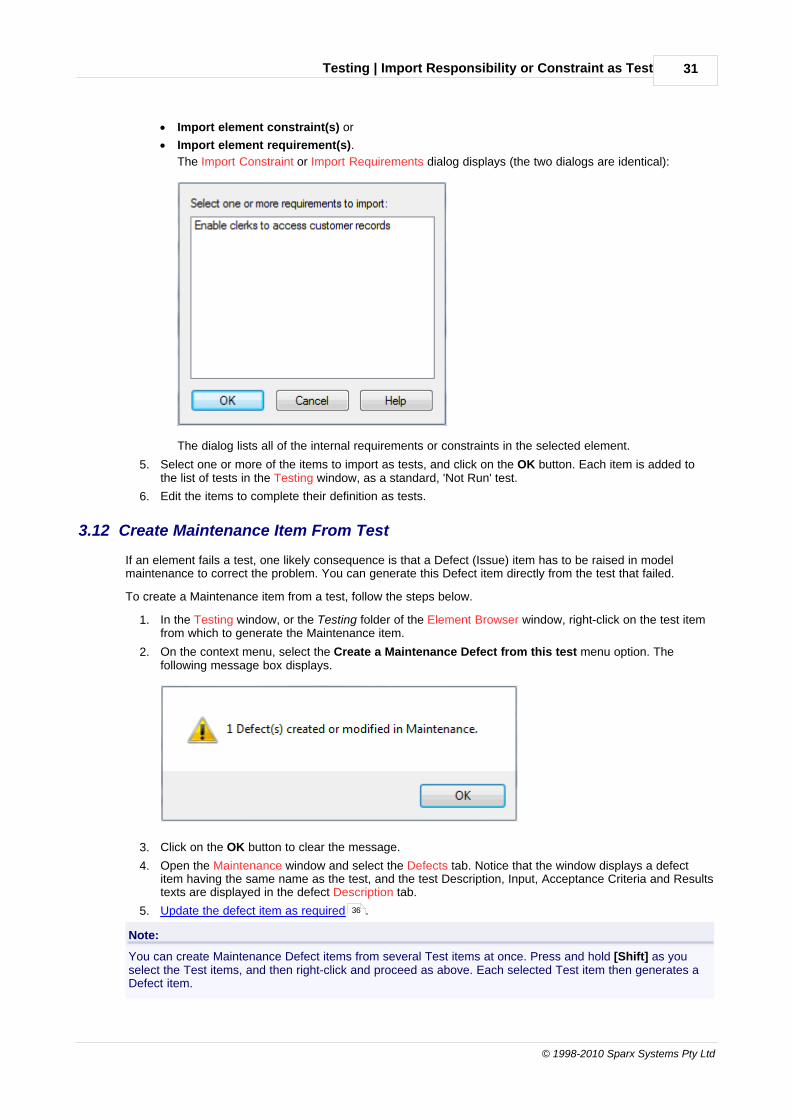
· Import element constraint(s) or
· Import element requirement(s).
The Import Constraint or Import Requirements dialog displays (the two dialogs are identical):
The dialog lists all of the internal requirements or constraints in the selected element.
5. Select one or more of the items to import as tests, and click on the OK button. Each item is added tothe list of tests in the Testing window, as a standard, 'Not Run' test.
6. Edit the items to complete their definition as tests.
3.12 Create Maintenance Item From Test
If an element fails a test, one likely consequence is that a Defect (Issue) item has to be raised in modelmaintenance to correct the problem. You can generate this Defect item directly from the test that failed.
To create a Maintenance item from a test, follow the steps below.
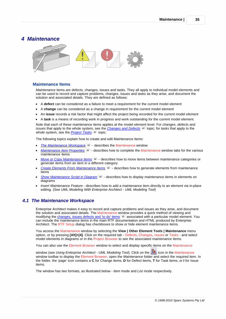
1. In the Testing window, or the Testing folder of the Element Browser window, right-click on the test itemfrom which to generate the Maintenance item.
2. On the context menu, select the Create a Maintenance Defect from this test menu option. Thefollowing message box displays.
3. Click on the OK button to clear the message.
4. Open the Maintenance window and select the Defects tab. Notice that the window displays a defectitem having the same name as the test, and the test Description, Input, Acceptance Criteria and Resultstexts are displayed in the defect Description tab.
5. Update the defect item as required .
Note:
You can create Maintenance Defect items from several Test items at once. Press and hold [Shift] as youselect the Test items, and then right-click and proceed as above. Each selected Test item then generates aDefect item.
36

Testing | Testing Details Report32
Project Management with Enterprise Architect
3.13 Testing Details Report
You can view the Testing Details dialog for a package, which enables you to run filtered reports on allelements in the package hierarchy under your selection. You can also print the report details.
To access the Testing Details dialog, right-click on a package in the Project Browser to display the contextmenu, and select the Documentation | Testing Details menu option.
The Testing Details dialog includes the following options:
Options Use to
Run By Select a name to filter for tests run by that person. Click on the x button toclear the field.
Checked By Select a name to filter for tests checked by that person. Click on the xbutton to clear the field.
Test Type Select the radio button for the required test type.
Status Select the radio button for the required status.
Locate Object (After clicking on an element in the Test Details list) locate the element inthe Project Browser.
Refresh Re-run the report query.
Print Print a summary of the test results.
3.14 Show Test Script Compartments
Any element that is capable of displaying a compartment can be used to show test scripts in a diagram. Tomake use of the feature the element must have an attached test. To use this feature follow the steps below:
1. Open a diagram containing the element with the attached test items.
2. Double-click on the diagram background to display the Diagram Properties dialog. Click on theElements tab.

Testing | Show Test Script Compartments 33
© 1998-2010 Sparx Systems Pty Ltd
3. In the Show Compartments panel, select the Testing checkbox.
4. Click on the OK button to save the setting.
The tests now appear as an item in the test scripts compartment of the diagram element.
3.15 Test Documentation
Enterprise Architect enables you to output the test scripts and results you have entered against elements inthe model, in Rich Text format. For more information on entering test scripts and details see the previoussections of the Testing topic.
To create the documentation, right-click on a package in the Project Browser and select the Documentation |Testing Report context menu option. The Generate Test Documentation dialog displays.
19

Testing | Test Documentation34
Project Management with Enterprise Architect
Note:
You can also access the Generate Test Documentation dialog by selecting the Project | Documentation |Testing Report menu option.
The Generate Test Documentation dialog enables you to set up your report. You can configure which tests toinclude or exclude in the report, whether to include child packages and what file to output to.
Maintenance | 35
© 1998-2010 Sparx Systems Pty Ltd
4 Maintenance
Maintenance Items
Maintenance items are defects, changes, issues and tasks. They all apply to individual model elements andcan be used to record and capture problems, changes, issues and tasks as they arise, and document thesolution and associated details. They are defined as follows:
· A defect can be considered as a failure to meet a requirement for the current model element
· A change can be considered as a change in requirement for the current model element
· An issue records a risk factor that might affect the project being recorded for the current model element
· A task is a means of recording work in progress and work outstanding for the current model element.
Note that each of these maintenance items applies at the model element level. For changes, defects andissues that apply to the whole system, see the Changes and Defects topic; for tasks that apply to thewhole system, see the Project Tasks topic.
The following topics explain how to create and edit Maintenance items:
· The Maintenance Workspace - describes the Maintenance window
· Maintenance Item Properties - describes how to complete the Maintenance window tabs for the variousmaintenance items
· Move or Copy Maintenance Items - describes how to move items between maintenance categories orgenerate items from an item in a different category
· Create Elements From Maintenance Items - describes how to generate elements from maintenanceitems
· Show Maintenance Script in Diagram - describes how to display maintenance items in elements ondiagrams
· Insert Maintenance Feature - describes how to add a maintenance item directly to an element via in-placeediting. (See UML Modeling With Enterprise Architect - UML Modeling Tool)
4.1 The Maintenance Workspace
Enterprise Architect makes it easy to record and capture problems and issues as they arise, and documentthe solution and associated details. The Maintenance window provides a quick method of viewing andmodifying the changes, issues defects and 'to do' items associated with a particular model element. Youcan include the maintenance items in the main RTF documentation and HTML produced by EnterpriseArchitect. The RTF Setup dialog has checkboxes to show or hide element maintenance items.
You access the Maintenance window by selecting the View | Other Element Tools | Maintenance menuoption, or by pressing [Alt]+[4]. Click on the required tab - Defects, Changes, Issues or Tasks - and selectmodel elements in diagrams or in the Project Browser to see the associated maintenance items.
You can also use the Element Browser window to select and display specific items on the Maintenance
window (see Using Enterprise Architect - UML Modeling Tool). Click on the icon in the Maintenancewindow toolbar to display the Element Browser, open the Maintenance folder and select the required item. Inthe folder, the 'page' icon contains a C for Change items, D for Defect items, T for Task items, or I for Issueitems.
The window has two formats, as illustrated below - Item mode and List mode respectively.
40
45
35
36
38
38
39
35
Maintenance | The Maintenance Workspace36
Project Management with Enterprise Architect
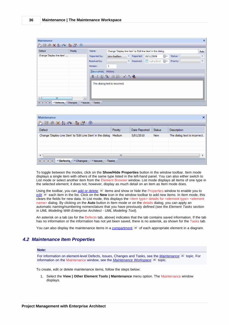
To toggle between the modes, click on the Show/Hide Properties button in the window toolbar. Item modedisplays a single item with others of the same type listed in the left-hand panel. You can also either switch toList mode or select another item from the Element Browser window. List mode displays all items of one type inthe selected element; it does not, however, display as much detail on an item as Item mode does.
Using the toolbar, you can add or delete items and show or hide the Properties window to enable you toedit each item in the list. Click on the New icon in the window toolbar to add new items. In Item mode, thisclears the fields for new data. In List mode, this displays the <item type> details for <element type> <elementname> dialog. By clicking on the Auto button in Item mode or on the details dialog, you can apply anautomatic naming/numbering nomenclature that you have previously defined (see the Element Tasks sectionin UML Modeling With Enterprise Architect - UML Modeling Tool).
An asterisk on a tab (as for the Defects tab, above) indicates that the tab contains saved information. If the tabhas no information or the information has not yet been saved, there is no asterisk, as shown for the Tasks tab.
You can also display the maintenance items in a compartment of each appropriate element in a diagram.
4.2 Maintenance Item Properties
Note:
For information on element-level Defects, Issues, Changes and Tasks, see the Maintenance topic. Forinformation on the Maintenance window, see the Maintenance Workspace topic.
To create, edit or delete maintenance items, follow the steps below:
1. Select the View | Other Element Tools | Maintenance menu option. The Maintenance windowdisplays.
36
36
39
35
35
Maintenance | Maintenance Item Properties 37
© 1998-2010 Sparx Systems Pty Ltd
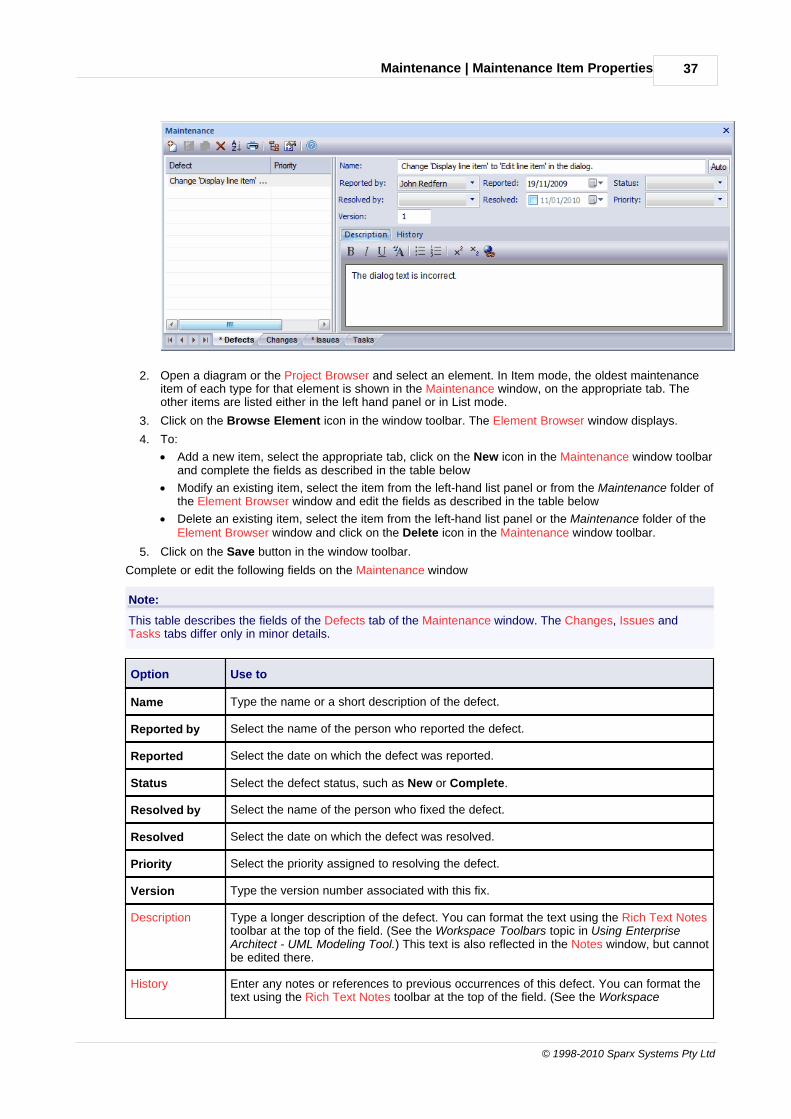
2. Open a diagram or the Project Browser and select an element. In Item mode, the oldest maintenanceitem of each type for that element is shown in the Maintenance window, on the appropriate tab. Theother items are listed either in the left hand panel or in List mode.
3. Click on the Browse Element icon in the window toolbar. The Element Browser window displays.
4. To:
· Add a new item, select the appropriate tab, click on the New icon in the Maintenance window toolbarand complete the fields as described in the table below
· Modify an existing item, select the item from the left-hand list panel or from the Maintenance folder ofthe Element Browser window and edit the fields as described in the table below
· Delete an existing item, select the item from the left-hand list panel or the Maintenance folder of theElement Browser window and click on the Delete icon in the Maintenance window toolbar.
5. Click on the Save button in the window toolbar.
Complete or edit the following fields on the Maintenance window
Note:
This table describes the fields of the Defects tab of the Maintenance window. The Changes, Issues andTasks tabs differ only in minor details.
Option Use to
Name Type the name or a short description of the defect.
Reported by Select the name of the person who reported the defect.
Reported Select the date on which the defect was reported.
Status Select the defect status, such as New or Complete.
Resolved by Select the name of the person who fixed the defect.
Resolved Select the date on which the defect was resolved.
Priority Select the priority assigned to resolving the defect.
Version Type the version number associated with this fix.
Description Type a longer description of the defect. You can format the text using the Rich Text Notestoolbar at the top of the field. (See the Workspace Toolbars topic in Using EnterpriseArchitect - UML Modeling Tool.) This text is also reflected in the Notes window, but cannotbe edited there.
History Enter any notes or references to previous occurrences of this defect. You can format thetext using the Rich Text Notes toolbar at the top of the field. (See the Workspace

Maintenance | Maintenance Item Properties38
Project Management with Enterprise Architect
Option Use to
Toolbars topic in Using Enterprise Architect - UML Modeling Tool.) This text is alsoreflected in the Notes window, but cannot be edited there.
4.3 Move or Copy Maintenance Items
When you define an item on the Defects, Changes, Issues or Tasks tab of the Maintenance window, you mightdecide that the item either is better suited to another Maintenance category, or forms a good template foritems in other categories. Enterprise Architect enables you to move or copy items between categories.
To move or copy a maintenance item, follow the steps below:
1. Open the Maintenance window and select the tab that contains the item you want to move or copy.
2. Right-click on the required maintenance item. The item context menu displays.
3. Click on the appropriate option - Move to or Copy to. A list of maintenance categories displays.
4. Click on the category to which to move or copy the item. A confirmatory prompt displays.
5. Click on the Yes button to confirm the move or copy.
6. Click on the target tab to ensure that the item has been added, and make any required changes .
4.4 Create Elements From Maintenance Item
A maintenance item identifies a defect, change, issue or task concerning an element. The maintenance itemcould itself be represented by an element if it has wider implications for the project or identifies - for example -an actor, activity or action that requires further definition.
You can create one or more elements from any maintenance item, using the Maintenance window. The newelement is connected to the maintenance item's parent element by a Dependency connector. The item itselfremains unchanged as a characteristic of its parent element.
To create an element from a maintenance item, follow the steps below:
1. Open the Maintenance window and select the tab that contains the item you want to create theelement from.
1. Right-click on the required maintenance item. The item context menu displays. select the Create asnew Element context menu option. The New Element dialog displays.
2. In the Name field, type a name for the new element.
3. In the Type field, click on the drop-down arrow and select the required element type. For example, youmight create an Issue element for a Defect or Issue maintenance item, a Change element for a Changeitem, or an Action for a Task item.
You can, however, create a wide range of other element types should any of these be appropriate, anduse the Select Group button to select a profile, MDG Technology or Add-In to create an elementspecific to that element group.
4. If necessary, in the Stereotype field click on the drop-down arrow and select a stereotype to apply tothe new element.
5. If you want to immediately define the properties of the element, select the Open Properties Dialog onCreation checkbox.
6. If you are adding multiple elements in one session, deselect the Close dialog on OK checkbox.
7. If you want to add the element to the currently-open diagram, select the Add to Current Diagramcheckbox.
8. Click on the OK button to create the element.
The element is added to the Project Browser and - if requested - to the current diagram.
35
36
35

Maintenance | Show Maintenance Script in Diagram 39
© 1998-2010 Sparx Systems Pty Ltd
4.5 Show Maintenance Script in Diagram
Any element that is capable of displaying a compartment can show maintenance scripts in a diagram. Tomake use of the feature the element must have an attached maintenance item.
To use this feature follow the steps below:
1. Open a diagram containing the element with the attached maintenance items.
2. Double-click on the diagram background to display the Diagram Properties dialog. Click on theElements tab.
3. In the Show Compartments panel, select the Maintenance checkbox.
4. Click on the OK button to save the setting.
The maintenance Items now appear as items in the maintenance scripts compartment of the diagram element.
35

Changes and Defects | 40
Project Management with Enterprise Architect
5 Changes and Defects
Change and Defect Elements
Changes and Defects are structured comments that can be used in managing change in a project. ADefect element (also known as an Issue element) corresponds to a failure to match the requirements for thecurrent system. A Change element corresponds to a change in requirements for the current system.
Using Structured Comments
You can track changes and defects (issues) in an Enterprise Architect model. Change and Defect elementscan be created in UML diagrams and connected using Realization, Dependency, Aggregation and otherrelationships to show what model element each affects and how each is resolved. You can edit the element properties , and assign people (as Actor elements) to changes and defects.
5.1 Defects (Issues)
A Defect (or Issue) element is a structured comment that contains information about defects and issues thatrelate to the system or model. This corresponds in some sense to a failure to meet defined requirements forthe current system. An Issue element looks the same as a Requirement element:
Enterprise Architect enables you to generate and handle issues in much the same way as you can handleand color code Requirements. See Requirements Management for more information.
You can link Issues using Realization connectors to model elements that are responsible for the defect. Youcan even structure a hierarchy of Issues using aggregation.
Note:
Issue elements can be created with or without an identifying I in the top right corner of the element. To togglethe display of this letter, select or deselect the Show stereotype icon for requirements checkbox on theOptions dialog, Objects page (see the Defaults and User Settings topic in Using Enterprise Architect - UMLModeling Tool).
Add an Issue Using the Enterprise Architect UML Toolbox
To add an Issue to the model using the Enterprise Architect UML Toolbox:
1. Open a Custom diagram.
2. From the Custom pages or Common page of the Enterprise Architect UML Toolbox, drag the Issue icononto the diagram.
3. Enter the details as required.
Add an Issue Using the Insert New Element Dialog
To add an Issue to the model using the Insert New Element dialog, follow the steps below:
1. Right-click on a package in the Project Browser.
41 40
42 43
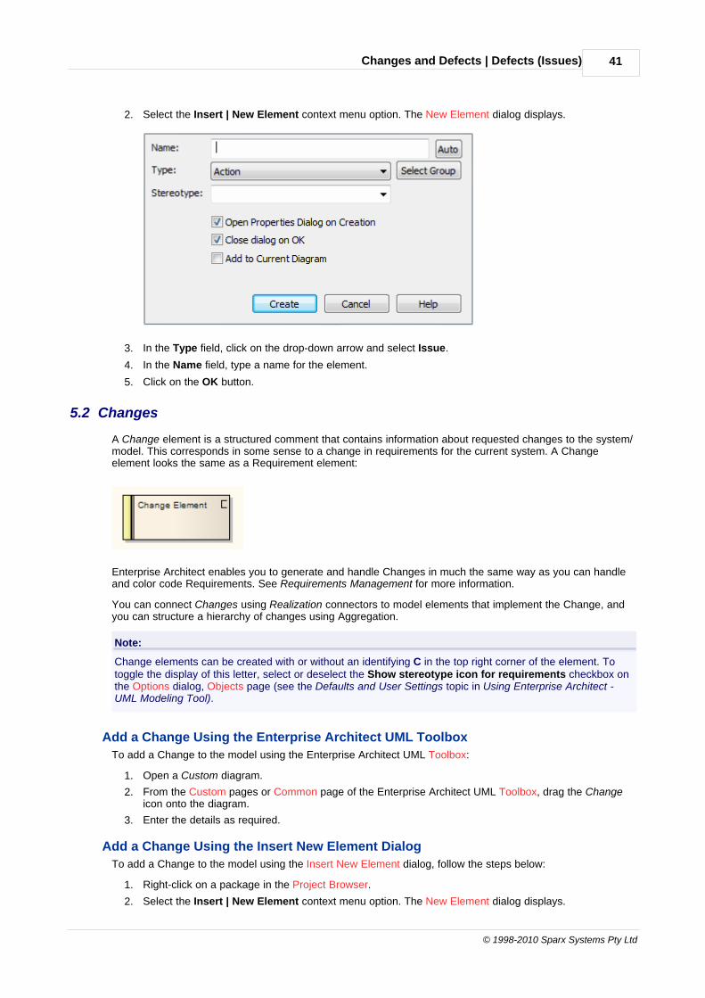
Changes and Defects | Defects (Issues) 41
© 1998-2010 Sparx Systems Pty Ltd
2. Select the Insert | New Element context menu option. The New Element dialog displays.
3. In the Type field, click on the drop-down arrow and select Issue.
4. In the Name field, type a name for the element.
5. Click on the OK button.
5.2 Changes
A Change element is a structured comment that contains information about requested changes to the system/model. This corresponds in some sense to a change in requirements for the current system. A Changeelement looks the same as a Requirement element:
Enterprise Architect enables you to generate and handle Changes in much the same way as you can handleand color code Requirements. See Requirements Management for more information.
You can connect Changes using Realization connectors to model elements that implement the Change, andyou can structure a hierarchy of changes using Aggregation.
Note:
Change elements can be created with or without an identifying C in the top right corner of the element. Totoggle the display of this letter, select or deselect the Show stereotype icon for requirements checkbox onthe Options dialog, Objects page (see the Defaults and User Settings topic in Using Enterprise Architect -UML Modeling Tool).
Add a Change Using the Enterprise Architect UML Toolbox
To add a Change to the model using the Enterprise Architect UML Toolbox:
1. Open a Custom diagram.
2. From the Custom pages or Common page of the Enterprise Architect UML Toolbox, drag the Changeicon onto the diagram.
3. Enter the details as required.
Add a Change Using the Insert New Element Dialog
To add a Change to the model using the Insert New Element dialog, follow the steps below:
1. Right-click on a package in the Project Browser.
2. Select the Insert | New Element context menu option. The New Element dialog displays.
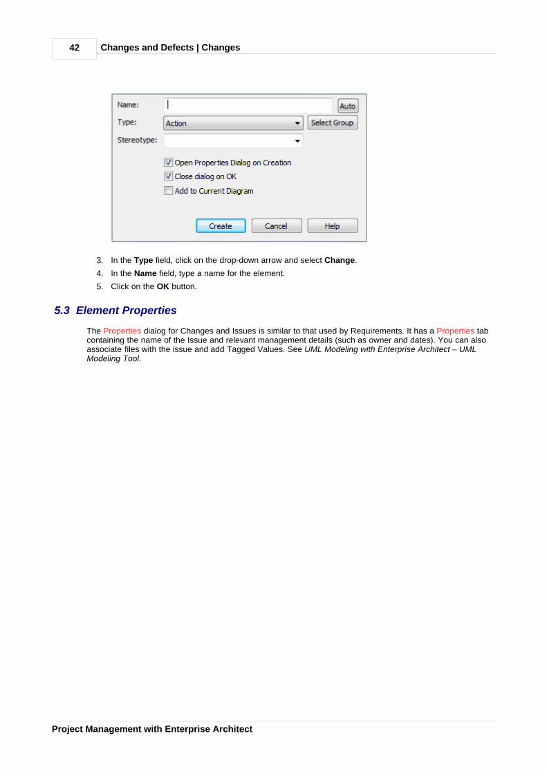
Changes and Defects | Changes42
Project Management with Enterprise Architect
3. In the Type field, click on the drop-down arrow and select Change.
4. In the Name field, type a name for the element.
5. Click on the OK button.
5.3 Element Properties
The Properties dialog for Changes and Issues is similar to that used by Requirements. It has a Properties tabcontaining the name of the Issue and relevant management details (such as owner and dates). You can also associate files with the issue and add Tagged Values. See UML Modeling with Enterprise Architect – UMLModeling Tool.

Changes and Defects | Element Properties 43
© 1998-2010 Sparx Systems Pty Ltd
5.4 Assign People to Defects or Changes
As an example of how you might use the Relationship Matrix to monitor issues or changes, the screen belowillustrates staff (actors) being linked through Realization connectors to Issues. Each highlighted squareindicates a responsibility of a staff member to work on or correct a named issue. This same approach can beused for any mix of model elements.

Changes and Defects | Assign People to Defects or Changes44
Project Management with Enterprise Architect

Project Tasks List | 45
© 1998-2010 Sparx Systems Pty Ltd
6 Project Tasks List
The Project Tasks List is a convenient 'To Do' list of major project work items that are not recorded elsewhere.It can also be used to track things like requests or meetings.
The Project Tasks List is available as a tab on the System window. To open the System window, select theView | Other Project Tools | System menu option, or press [Alt]+[2]. Select the Project Tasks tab.
Right-click on the list to view the context menu, and select to add, modify or delete list items, or to set a statusfilter. To set the sort order, click the title-bar of the column on which to index the tasks.
For more information see the Add, Modify and Delete Tasks topic.
Tip:
Select the Print List menu option to print out the currently displayed items.
Note:
You can transport these task definitions between models, using the Export Reference Data and ImportReference Data options on the Tools menu. See the Reference Data topic in UML Model Management.
6.1 Add, Modify and Delete Tasks
From the Project Tasks tab on the System window, display the Task Detail dialog to Add , Modify andDelete tasks.
Add a Task
To add a task, follow the steps below:
1. Double-click in a blank area of the Project Tasks tab, or right-click and select the Add New contextmenu option. The Task Detail dialog displays.
45
45 47
47
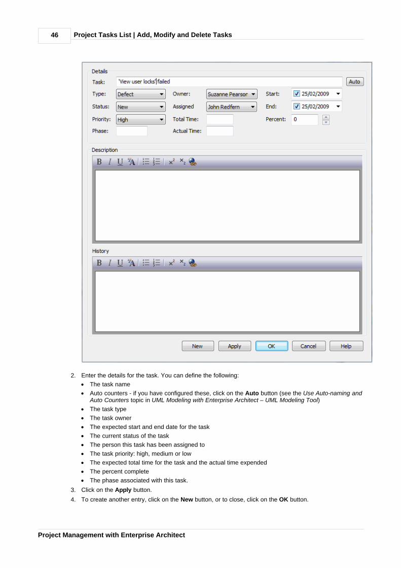
Project Tasks List | Add, Modify and Delete Tasks46
Project Management with Enterprise Architect
2. Enter the details for the task. You can define the following:
· The task name
· Auto counters - if you have configured these, click on the Auto button (see the Use Auto-naming andAuto Counters topic in UML Modeling with Enterprise Architect – UML Modeling Tool)
· The task type
· The task owner
· The expected start and end date for the task
· The current status of the task
· The person this task has been assigned to
· The task priority: high, medium or low
· The expected total time for the task and the actual time expended
· The percent complete
· The phase associated with this task.
3. Click on the Apply button.
4. To create another entry, click on the New button, or to close, click on the OK button.

Project Tasks List | Add, Modify and Delete Tasks 47
© 1998-2010 Sparx Systems Pty Ltd
Modify a Task
To modify a task, on the Project Tasks tab, either:
· Double-click on the task to modify, or
· Right-click on the task to modify and, from the context menu, select the Modify Selected menu option.
The Task Detail dialog displays, and you can edit the task data.
Delete a Task
To delete a task, follow the steps below:
1. On the Project Tasks tab, right-click on the task to delete. The context menu displays.
2. Select the Delete menu option.
Project and Model Issues | 48
Project Management with Enterprise Architect
7 Project and Model Issues
Any identified issues can be recorded against the current project. Issues are raised with a description, date,owner and status.
Note:
You can transport these issue definitions between models, using the Export Reference Data and ImportReference Data options on the Tools menu. See the Reference Data topic in UML Model Management.
You can add, delete and modify Issues using either the Project Issues dialog, or the Issue Detaildialog from the Project Issues tab of the System window. You can also generate and view an RTF report ofyour issue list, using either the Project Issues dialog or the Project Issues tab.
Tip:
You can view sample report output in the Report Output Sample topic.
7.1 Project Issues Dialog
The Project Issues dialog is accessed from the Project | Documentation | Issues menu option. This dialogenables you to record a description, date, owner and status of any identified issues against the current project.You can add, modify and delete issues , and generate a report of your project issues in Rich TextFormat.
51 48 50
51 52
52
51 51
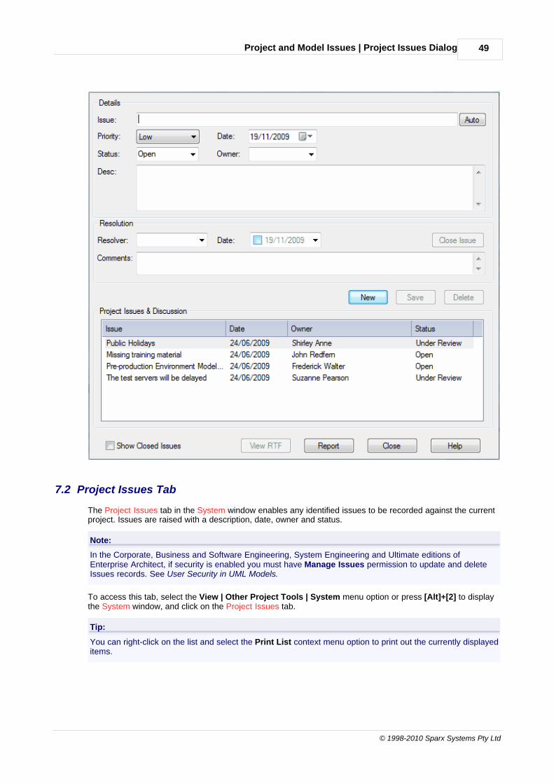
Project and Model Issues | Project Issues Dialog 49
© 1998-2010 Sparx Systems Pty Ltd
7.2 Project Issues Tab
The Project Issues tab in the System window enables any identified issues to be recorded against the currentproject. Issues are raised with a description, date, owner and status.
Note:
In the Corporate, Business and Software Engineering, System Engineering and Ultimate editions ofEnterprise Architect, if security is enabled you must have Manage Issues permission to update and deleteIssues records. See User Security in UML Models.
To access this tab, select the View | Other Project Tools | System menu option or press [Alt]+[2] to displaythe System window, and click on the Project Issues tab.
Tip:
You can right-click on the list and select the Print List context menu option to print out the currently displayeditems.
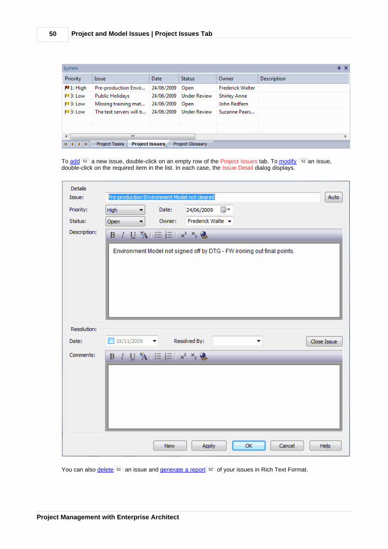
Project and Model Issues | Project Issues Tab50
Project Management with Enterprise Architect
To add a new issue, double-click on an empty row of the Project Issues tab. To modify an issue,double-click on the required item in the list. In each case, the Issue Detail dialog displays.
You can also delete an issue and generate a report of your issues in Rich Text Format.
51 51
51 52

Project and Model Issues | Add, Delete and Modify Issues 51
© 1998-2010 Sparx Systems Pty Ltd
7.3 Add, Delete and Modify Issues
Issues can be added, deleted and modified using either the Project Issues dialog, or the Issue Detaildialog from the Project Issues tab of the System window.
To add an issue, click on the New button and complete the following fields:
Component Description
Issue The name of the issue.
Auto Click on the Auto button if you have auto counters configured.(See the Use Auto-naming and Auto Counters topic in UMLModeling with Enterprise Architect – UML Modeling Tool.)
Priority The priority of this issue: low, medium or high.
Date The date the issue arose.
Status The issue's current status.
Owner The person owning the issue.
Description Description of the issue.
Resolution Notes on the resolution of the issue.
Date The date the issue was resolved.
Resolved By Person who resolved the issue.
Comments Any comments regarding the resolution of the issue.
Close Issue Click on this button to close the issue.
Apply Save and apply the issue.
To modify an issue, double-click on it in the Project Issues tab or Project Issues & Discussion list, then edit thefields as indicated in the above table.
To delete an issue, click on it in the Project Issues tab or Project Issues & Discussion list, then:
· Click on the Delete button (Project Issues dialog) or
· Right-click on the issue and select the Delete option from the context menu.
7.4 Report From Project Issues Dialog
To generate an RTF document of your issue log using the Project Issues dialog, follow the steps below:
1. Select the Project | Documentation | Issues menu option. The Project issues dialog displays.
2. Click on the Report button. The Save As dialog displays.
3. Browse for the appropriate file location and, in the File name field, type the file name for the report.
4. Click on the Save button.
5. To view the report, click on the View RTF button.
Tip:
For information on viewing sample report output, see the Report Output Sample topic.
48 50
52

Project and Model Issues | Report From Project Issues Tab52
Project Management with Enterprise Architect
7.5 Report From Project Issues Tab
To generate an RTF document of your issue log using the Project Issues tab of the System window, follow thesteps below:
1. Select the View | Other Project Tools | System menu option, or press [Alt]+[2]. The System windowdisplays.
2. Click on the Project Issues tab.
3. Right-click on a blank line of the Project Issues tab and select the Create RTF Report context menuoption. The Save As dialog displays.
4. Enter the directory location and file name to save your report to and click on the Save button. EnterpriseArchitect generates the report. This should only take a few moments to complete.
Tip:
For information on viewing sample report output, see the Report Output Sample topic.
7.6 Report Output Sample
An example of the output from an Issues report is shown below:
List of Project Issues: 24-Jul-2007 9:47:00 AM
Issue Date/Owner Description Resolution
Test servers will bedelayed
24/07/2007 EloiseNorman
The test server builds havebeen delayed because theparticular (unusual) memoryrequirements to match thecustomer's site are notavailable on shore. They arebeing sourced from Singaporebut it will delay the builds anddelivery of the machines.
Closed: 24/07/2007Geoffrey Sparks Themachines will be builtand delivered usingstandard memory andthe proprietary memorywill be added later. Allperformance tests willbe delayed until thememory is available.
Public Holidays 24/07/2007 JoannaStoat
The schedule includes staffworking on public holidays. Anumber of staff have indicatedthat contrary to what theystated earlier they are notavailable.
Open: 24/07/2007
Compiler Versiondisparity
24/07/2007 EloiseNorman
A number of the developershave downloaded differentversions of a number of thecompilers. This has lead tounpredictable buildsimpacting on testing.
Under Review:24/07/2007
52
Project Glossary | 53
© 1998-2010 Sparx Systems Pty Ltd
8 Project Glossary
The glossary enables you to set up a list of defined terms for your project. You can further divide the items bycategory; for example, Business terms and Technical terms. The glossary can be saved in Rich Text format forinclusion as part of a larger project document.
You can add, delete and modify the project glossary entries through the Glossary dialog or through theProject Glossary tab on the System window. You can also create glossary terms and definitions from textin the Notes window or from any Notes or Description fields that have the Rich Text Notes toolbar. Oncethese terms exist, you can insert them into any of those same fields by pressing [Ctrl]+[Space] and selectingthem from an autocompletion box (see Using Enterprise Architect - UML Modeling Tool).
Tip:
Include a Glossary Report in your project requirements or functional specifications documents.
Note:
You can transport these glossary definitions between models, using the Export Reference Data and ImportReference Data options on the Tools menu. See the Reference Data topic in UML Model Management.
8.1 The Glossary Dialog
To open the Glossary dialog, select the Project | Documentation | Glossary menu option. Use this dialog toadd , modify and delete glossary entries. You can also limit the display to list entries of aspecific type for editing or deletion.
53
55
57
54 55 55 55

Project Glossary | The Glossary Dialog54
Project Management with Enterprise Architect
Option Use to
Glossary Term Type the term to include in the glossary.
Glossary Type Select either Technical or Business.
If you require a different glossary type, click on the [ ... ] (browse) buttonand specify the name of the new type.
This field applies the type only to the selected term. You can rename atype for all terms of that type , using the Project Glossary tab of theSystem window.
Description Type the definition or description of the term.
You can format the text of this description using the Rich Text Notestoolbar at the top of the field (see Using Enterprise Architect - UMLModeling Tool).
Limit Display To Select the appropriate type to filter the Type | Term list to show entries ofa specific type for editing or deletion.
Type | Term Review the list of defined glossary terms.
Report Print a glossary report .
Add a Glossary Entry
To add an entry to the glossary, follow the steps below:
55
57

Project Glossary | The Glossary Dialog 55
© 1998-2010 Sparx Systems Pty Ltd
1. Enter the details for the glossary item: the Glossary Term, the Glossary Type and the Description.
Note:
A glossary term must have a defined type and description. You cannot save a new term without both ofthese values.
2. Click on the Save button.
3. To enter another item, click on the New button.
Modify a Glossary Entry
To modify a glossary entry, follow the steps below:
1. Select the entry to modify from the bottom panel of the dialog. The details of the entry display in thefields in the top half of the window.
Note:
A glossary term must have a defined type and description. You cannot save an edited term withoutboth of these values.
2. Change the details as required.
3. Click on the Save button.
Delete a Glossary Entry
To delete a glossary entry, follow the steps below:
1. Select the entry to delete from the bottom panel of the dialog. The details of the entry display in thefields in the top half of the window.
2. Click on the Delete button.
Limit the Display
You can select which entry categories are displayed in the list. To:
· View all glossary entries, select the All value in the Limit Display To field.
· View entries of a specific type only, select the appropriate value in the Limit Display To field.
8.2 Project Glossary Tab
The Project Glossary tab in the System window shows all of the items in your model's glossary. This tab listsall the glossary terms already defined for a model. You can add to the list, delete or change items, change adefinition type for all terms of that type, and filter the list to exclude by type.
Access this tab by opening the System window; select the View | Other Project Tools | System menu optionor press [Alt]+[2]. Select the Project Glossary tab.
Tip:
To print out all of the currently listed items, right-click on the list and select the Print List context menuoption.
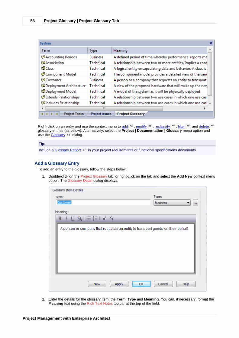
Project Glossary | Project Glossary Tab56
Project Management with Enterprise Architect
Right-click on an entry and use the context menu to add , modify , reclassify , filter and deleteglossary entries (as below). Alternatively, select the Project | Documentation | Glossary menu option anduse the Glossary dialog.
Tip:
Include a Glossary Report in your project requirements or functional specifications documents.
Add a Glossary Entry
To add an entry to the glossary, follow the steps below:
1. Double-click on the Project Glossary tab, or right-click on the tab and select the Add New context menuoption. The Glossary Detail dialog displays.
2. Enter the details for the glossary item: the Term, Type and Meaning. You can, if necessary, format theMeaning text using the Rich Text Notes toolbar at the top of the field.
56 57 57 57 57
53
57
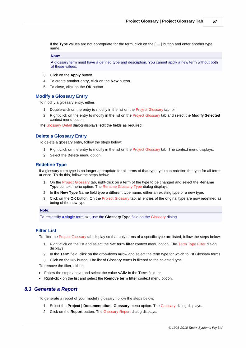
Project Glossary | Project Glossary Tab 57
© 1998-2010 Sparx Systems Pty Ltd
If the Type values are not appropriate for the term, click on the [ ... ] button and enter another typename.
Note:
A glossary term must have a defined type and description. You cannot apply a new term without bothof these values.
3. Click on the Apply button.
4. To create another entry, click on the New button.
5. To close, click on the OK button.
Modify a Glossary Entry
To modify a glossary entry, either:
1. Double-click on the entry to modify in the list on the Project Glossary tab, or
2. Right-click on the entry to modify in the list on the Project Glossary tab and select the Modify Selectedcontext menu option.
The Glossary Detail dialog displays; edit the fields as required.
Delete a Glossary Entry
To delete a glossary entry, follow the steps below:
1. Right-click on the entry to modify in the list on the Project Glossary tab. The context menu displays.
2. Select the Delete menu option.
Redefine Type
If a glossary term type is no longer appropriate for all terms of that type, you can redefine the type for all termsat once. To do this, follow the steps below:
1. On the Project Glossary tab, right-click on a term of the type to be changed and select the RenameType context menu option. The Rename Glossary Type dialog displays.
2. In the New Type Name field type a different type name, either an existing type or a new type.
3. Click on the OK button. On the Project Glossary tab, all entries of the original type are now redefined asbeing of the new type.
Note:
To reclassify a single term , use the Glossary Type field on the Glossary dialog.
Filter List
To filter the Project Glossary tab display so that only terms of a specific type are listed, follow the steps below:
1. Right-click on the list and select the Set term filter context menu option. The Term Type Filter dialogdisplays.
2. In the Term field, click on the drop-down arrow and select the term type for which to list Glossary terms.
3. Click on the OK button. The list of Glossary terms is filtered to the selected type.
To remove the filter, either:
· Follow the steps above and select the value <All> in the Term field, or
· Right-click on the list and select the Remove term filter context menu option.
8.3 Generate a Report
To generate a report of your model's glossary, follow the steps below:
1. Select the Project | Documentation | Glossary menu option. The Glossary dialog displays.
2. Click on the Report button. The Glossary Report dialog displays.
53

Project Glossary | Generate a Report58
Project Management with Enterprise Architect
3. In the Filename field, type or select a filename for the glossary.
4. In the Heading field, type a suitable heading for the glossary.
5. In the Include Glossary Items panel, select the checkbox for each type of glossary entry to include. Clickon the Select All button to select all types of entry.
6. If necessary, click on the Page Setup and/or Language buttons to define the page setup and languagefor the report.
7. To include page breaks, select the Page break between sections checkbox.
8. Click on the Generate button to generate the report.
9. Click on the View button to open the report.
Note:
You can view sample report output in the Glossary Report Output Sample topic.
8.4 Glossary Report Output Sample
An example of the output from a Glossary report is shown below:
Glossary
Business Terms
Accounting PeriodsA defined period of time whereby performance reports can be extracted. (normally 4week periods).
CustomerA person or a company that requests An entity to transport goods on their behalf.
Technical Terms
AssociationA relationship between two or more entities. Implies a connection of some type - for
58

Project Glossary | Glossary Report Output Sample 59
© 1998-2010 Sparx Systems Pty Ltd
example one entity uses the services of another, or one entity is connected to anotherover a network link.
Component ModelThe component model provides a detailed view of the various hardware and softwarecomponents that make up the proposed system. It shows both where these componentsreside and how they inter-relate with other components. Component requirementsdetail what responsibilities a component has to supply functionality or behavior withinthe system.
Deployment ModelA model of the system as it is physically deployed.
Extends RelationshipA relationship between two Use Cases in which one Use Case 'extends' the behavior ofanother. Typically this represents optional behavior in a Use Case scenario - forexample a user might optionally request a list or report at some point in a performing abusiness Use Case.

Update Package Status | 60
Project Management with Enterprise Architect
9 Update Package Status
Elements in Enterprise Architect can be assigned a current status, such as Proposed, Validated or Mandatory.Often a complete package structure is updated from one status to another (or released) at the same time. Tohelp facilitate this, Enterprise Architect supports a 'bulk' update of element status at the same time.
Update Element Status for a Complete Package Structure
To update element status for a complete package structure, follow the steps below:
1. In the Project Browser, right-click on the package to update. The context menu displays.
2. Select the Package Control | Update Package Status menu option. The Status Update dialogdisplays.
3. Select:
· The new status
· Whether to recursively descend the package tree
· Whether to include elements
· Whether to include element requirements
· Whether to include element constraints
4. Click on the OK button. Enterprise Architect updates all required elements to the new status.

Manage Bookmarks | 61
© 1998-2010 Sparx Systems Pty Ltd
10 Manage Bookmarks
Bookmarks are small red triangles that display above elements in diagrams when the element has been'bookmarked'. A bookmark is a visual clue that something is different about an element; the meaning is up toyou.
Tip:
The Model Search window also enables searching based on bookmarked elements. See the Model Searchtopic in Using Enterprise Architect - UML Modeling Tool.
You can bookmark a selected element in a diagram manually by pressing [Shift]+[Spacebar]. You clear thebookmark by pressing [Shift]+[Spacebar] again.
Bookmark Multiple Elements
You can also bookmark all elements in a folder (and their children) using the Manage Bookmarks dialog.Right-click on the parent package in the Project Browser and select the Bookmarks context menu option.
This dialog enables you to automatically bookmark elements that have new changes or defects defined in the Maintenance window, or test scripts defined in the Testing window. This is useful to highlight elementsthat have additional project information.
You can click on the Clear All button to clear all elements in the current tree of bookmarks. You should reloadthe project to show the new or cleared bookmarks ([Ctrl]+[Shift]+[F11]) - see Version Control Within UMLModels Using Enterprise Architect.
35 20
Index62
Project Management with Enterprise Architect
Index- A -Acceptance Testing 25
Add
Element Changes 36
Element Defects 36
Element Issues 36
Element Tasks 36
Project Task 45
Test Details 21
Assign
People To Changes 43
People To Defects 43
- B -Bookmark
Multiple Elements 61
Triangle 61
- C -Calibration
Of Project Factors 3
Change
Element 40
Change Element
Hide Stereotype Letter 41
Show Stereotype Letter 41
Constraint
Internal, Import As Test 30
Copy
Maintenance Item Between Categories 38
Test Between Categories 27
Create
Element From Maintenance Item 38
- D -Default
Hours 8
Default Hours
Estimation 8
Per Adjusted Use Case Point 8
Project Management 8
Rate 8
Settings 8
Defect
Add 40
Create From Test Item 31
Element 40
Hide Stereotype Letter 40
Show Stereotype Letter 40
Defined Environment Types 5
Delete
Element Changes 36
Element Defects 36
Element Issues 36
Element Tasks 36
Project Task 45
- E -ECF
Value 5
Weighting 5
Edit
Test Details 21
Effort Management 11
Effort Types
Define 15
Global 15
Non-Global 11
Element
Bulk Update 60
Change 40, 41
Changes And Issues 35
Changes, Add/Modify/Delete 36
Create From Maintenance Item 38
Defect 40
Defects 35
Defects, Add/Modify/Delete 36
Issue 40
Issues And Changes 35
Issues, Add/Modify/Delete 36
Maintenance 35
Multiple Update 60
Phase, Update For Package 60
Properties Dialog, Changes and Defects 42
Status, Update For Package 60
Tasks 35
Tasks, Add/Modify/Delete 36
Test Scripts Compartment 32
Version, Update For Package 60
Environment Complexity Factor
Definition 5
Estimate Project Size 6
Index 63
© 1998-2010 Sparx Systems Pty Ltd
Environment Complexity Factor
Estimation 5
Value 5
Weighting 5
Estimation
Default Hours 8
Environment Complexity Factors 5
Of Project Factors 3
Of Project Size 6
Of Project Timescale 3
Technical Complexity Factors 3
- G -Global Risks 17
Glossary
Add Item, Glossary Dialog 53
Delete Item, Glossary Dialog 53
Dialog 53
Filter List, Glossary Dialog 53
Model 53
Modify Item, Glossary Dialog 53
Project 53
Report 57
Report Output Sample 58
Glossary Detail Dialog
Add Item 55
Modify Item 55
- H -Hourly Rate 8
- I -Import
Scenario as Test 27
Scenarios From Package 27
Test From Other Element 29
Integration Testing
Display Details 23
Issue
Create From Test Item 31
Issue (Defect)
Add 40
Element 40
Hide Stereotype Letter 40
Show Stereotype Letter 40
Issue (Project)
Add 51
Delete 51
Model 48
Modify 51
Report, Generate 48
Issues Report
Sample Output 52
Via Project Issues Tab 52
- M -Maintenance
Asterisk On Maintenance Window Tabs 35
Create Defect Item From Test 31
Items 35
Of Element Properties 36
Script, Show In Compartments 39
Support 36
Workspace 35
Maintenance Item
Copy Between Categories 38
Create Element From 38
Move Between Categories 38
Manage
Bookmarks 61
Metric Types
Define 16
Global 16
Non-Global 13
Metrics And Estimation
Default Hour Rate 8
ECF 5
Effort Types 15
Environment Complexity Factors 5
For An Element 13
Metric Types 16
Risk Types 17
TCF 3
Technical Complexity Factors 3
Model
Glossary 53
Issues 48
Model Glossary
Add Item, Glossary Detail Dialog 55
Add Item, Glossary Dialog 53
Delete Item, Glossary Dialog 53
Delete Item, Project Glossary Tab 55
Filter List, Glossary Dialog 53
Filter List, Project Glossary Tab 55
Glossary Dialog 53
Glossary Report 57
Modify Item, Glossary Detail Dialog 55
Modify Item, Glossary Dialog 53

Index64
Project Management with Enterprise Architect
Model Glossary
Project Glossary Tab 55
Redefine Entry Type, Project Glossary Tab 55
Modify
Element Changes 36
Element Defects 36
Element Issues 36
Element Tasks 36
Project Task 45
Move
Maintenance Item Between Categories 38
Test Between Categories 27
- P -Package
Phase, Update 60
Status, Update 60
Version, Update 60
Package Scenarios
Import As Test Scenarios 27
People
Assign To Changes 43
Assign To Defects 43
Project Issues 49
Task List 45
Project
Estimation 3
Glossary 53
Issues 48
Metrics 3
Timescale Estimation 3
Project Factor Calibration 3
Project Glossary
Add Item, Glossary Detail Dialog 55
Add Item, Glossary Dialog 53
Delete Item, Glossary Dialog 53
Delete Item, Project Glossary Tab 55
Filter List, Glossary Dialog 53
Filter List, Project Glossary Tab 55
Glossary Dialog 53
Glossary Report 57
Modify Item, Glossary Detail Dialog 55
Modify Item, Glossary Dialog 53
Redefine Entry Type, Project Glossary Tab 55
Tab 55
Project Indicators
Risk Types 17
Project Issue
Add 51
Delete 51
Dialog 48
Modify 51
Print List 49
Record 48
Report, Via Project Issues Dialog 51
Report, Via Project Issues Tab 52
Tab 49
Project Management
Asterisk On Window Tabs 9
Default Hours 8
Effort Management 11
Effort Types 15
Environment Complexity Factors 5
Introduction 2
Maintenance 35
Metric Types 16
Metrics 13
Resource Allocation 10
Resource Report 14
Risk Management 12
Risk Types 17
Technical Complexity Factors 3
Window 9
With Enterprise Architect 2
Project Task
Add 45
Delete 45
List 45
Modify 45
Tab, Print List 45
- R -Red
Triangle 61
Report
Project Issues, Via Project Issues Dialog 51
Project Issues, Via Project Issues Tab 52
Testing Details 32
Requirement
Internal, Import As Test 30
Resource
Allocation 10
And Tasking Details Dialog 14
Report 14
Resource Management 9
Effort Types 15
Metric Types 16
Risk Types 17
Responsibility

Index 65
© 1998-2010 Sparx Systems Pty Ltd
Responsibility
Import As Test 30
Risk
Management 12
Risk Types
Define 17
Global 17
Non-Global 12
- S -Scenario
Testing 26
Settings
Default Hours 8
Effort Types 15
Environment Complexity Factors 5
Metric Types 16
Risk Types 17
Technical Complexity Factors 3
System
Testing 24
System Window
Project Glossary Tab 55
Project Issues Tab 49
Project Tasks Tab 45
- T -Task
Completion 10
Details 45
TCF
Value 3
Weighting 3
Technical Complexity Factor
Estimate Project Size 6
Value 3
Weighting 3
Test
Copy Between Categories 27
Create Defect From 31
Documentation 33
Import From Other Element 29
Move Between Categories 27
Report 33
Result Output 33
Script Output 33
Test Details Dialog 21
Test Scripts
Compartment 32
Testing
Acceptance 25
Asterisk On Testing Window Tabs 20
Autonaming 20
Import Element Scenarios 27
Import Internal Constraint 30
Import Internal Requirement 30
Import Package Scenarios 27
Import Responsibility 30
Integration 23
Overview 19
Scenario 26
Support 19
System 24
Unit 22
Window 20
Window, Acceptance Test Tab 25
Window, Integration Test Tab 23
Window, Scenario Test Tab 26
Window, System Test Tab 24
Window, Unit Test Tab 22
Workspace 20
Testing Details Report 32
Triangle
Red 61
- U -Unadjusted Use Case Points 6
Unit Testing 22
Update
Element Phase, For Package 60
Element Status, For Package 60
Element Version, For Package 60
Package Phase 60
Package Status 60
Package Version 60
Use Case
Keyword 6
Metrics 3
Metrics Dialog 6
Phase 6
Points, Unadjusted 6
UUCP
Estimate Project Size 6

Project Management with EnterpriseArchitect
www.sparxsystems.com