Project Insights and Best Practices - ACEC
42
6/25/2018 1 Project Insights and Best Practices for MaineDOT Highway Design Session 1: June 26, 2018 Purpose To provide a learning opportunity for designers to share their own project specific and general experiences, and receive clarification and answers to questions related to MaineDOT Policies, Engineering Instructions (EI’s), and Design Guidance, with the intent of improving the overall quality and consistency of the Highway Design process, submissions received from consultants and internal MaineDOT Highway design teams.
Transcript of Project Insights and Best Practices - ACEC
6/25/2018
1
Project Insights and
Best Practicesfor
MaineDOT Highway Design
Session 1: June 26, 2018
Purpose
To provide a learning opportunity for designers to share their own project specific and general experiences, and receive clarification and answers to questions related to MaineDOT Policies, Engineering Instructions (EI’s), and Design Guidance, with the intent of improving the overall quality and consistency of the Highway Design process, submissions received from consultants and internal MaineDOT Highway design teams.
6/25/2018
2
• Idea originally raised during a Highway Subcommittee Meeting regarding:
• potential lack of consistency of design submissions (including different submissions from the same consultant)
• passing down/sharing of information with newer staff
• sharing of information between consultants
• The subcommittee felt this warranted further exploration and took it on as a goal.
• Subcommittee members involved in initial discussions:
• Tony Grande – VHB
• Don Ettinger – Gorrill Palmer
• Dale Mitchell – HNTB
• Kevin Ducharme – T.Y. LIN
Process (1 of 5)
Process (2 of 5)
• Topics Covered were mainly based on the Highway Design Guide:
1. Pre‐Scoping or General Policy Discussion Points
2. Typical Sections
3. Alignment (H/V)
4. Geometric Layout
5. Drainage
6. Cross Sections
7. Guardrail
8. Quantities/Estimating
9. Geotechnical
6/25/2018
3
• With this list as the focus, polled our own internal design teams, for:
• Project‐specific experiences worth sharing
• Design questions or areas where clarification would be helpful
• Any other topics that may not be listed
• Lists from all four firms were then combined
• Held several meetings, included our experienced designers, shared some project experiences, and vetted through each item on the combined list
• Results were then compressed, and refined for discussion with MaineDOT
Process (3 of 5)
• (3) meetings with MaineDOT, and included our experienced designers
• September 28, 2017
• October 20, 2017
• November 1, 2017
• MaineDOT Highway Program involved in discussions:
• Brad Foley
• Steve Bodge
• Andy MacDonald
• Atlee Mousseau
• Shawn Smith
• Denis Lovely
Process (4 of 5)

6/25/2018
4
• Meetings were very interactive, discussions included:
• project specific examples,
• policy discussion points
• general design issues
• other issues that came about as a result of discussion
Process (5 of 5)
• Review the results
• Interactive discussion
• Meeting feedback included in final document
• Final document available on MaineDOT Highway webpage.
Today’s Meeting

6/25/2018
5
Presentation of Results
Pre‐Scoping and General Policy
6/25/2018
6
1. Pre‐Scoping and General Policy (1 of 11)
A. HDR Forms: Is MaineDOT providing the initial HDR Forms already filled out for all projects?
To be discussed at the Initial Team Meeting
Any special situations regarding design criteria should be brought up during the meeting.
1. Pre‐Scoping and General Policy (2 of 11)
B. Signing and Striping Plans: included as part of the consultant’s scope, or determined on a project by project basis?
Determined on a project by project basis, discuss at Pre‐Scoping Meeting
Detour plans may also need to be considered and included
At a minimum, should include labels for all striping

6/25/2018
7
1. Pre‐Scoping and General Policy (3 of 11)
C. Development of 3D Model: should this be assumed for every project? Delivery with Final PSE package, or after advertise?
Assume 3D Model is required (unless told otherwise)
3D Model delivered with the Final PSE package
3D Models currently being considered for Paving projects
Published Plans are the “controlling” document where 3D model differs
1. Pre‐Scoping and General Policy (4 of 11)
D. Right of Way: what level of effort is required for property owner review and coordination?
At a minimum, Property Owner Reports (POR’s) provided by MaineDOT should be reviewed, and any special considerations noted
May require meetings with select individual property owners to review the project (this would be on a case by case basis – coordinated with MaineDOT PM)
Combined MaineDOT/Consultant Team site reviews are typically very helpful, when possible

6/25/2018
8
1. Pre‐Scoping and General Policy (5 of 11)
E. EI/Design Guidance: at what point in the design should a recent update be incorporated into a project, and at what point is it considered too late to change?
Any new guidance should be incorporated, up to PDR
Beyond PDR, check with the PM
Decisions should be based on the nature of the update and the significance of the changes
1. Pre‐Scoping and General Policy (6 of 11)
F. Truck Climbing Lane Analysis: should be identified early on if this analysis will be included in a project, or not.
Project dependent
Assume Truck Analysis will be required
Confirm at Initial Team Meeting
6/25/2018
9
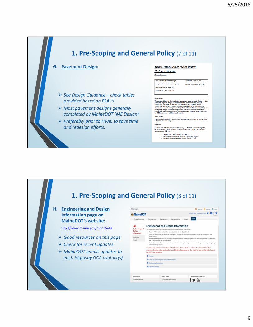
1. Pre‐Scoping and General Policy (7 of 11)
G. Pavement Design:
See Design Guidance – check tables provided based on ESAL’s
Most pavement designs generally completed by MaineDOT (ME Design)
Preferably prior to HVAC to save time and redesign efforts.
1. Pre‐Scoping and General Policy (8 of 11)
H. Engineering and Design Information page on MaineDOT’s website:
http://www.maine.gov/mdot/edi/
Good resources on this page
Check for recent updates
MaineDOT emails updates to each Highway GCA contact(s)

6/25/2018
10
1. Pre‐Scoping and General Policy (9 of 11)
H. Highway Program Consultant Information page on MaineDOT’s website:
http://www.maine.gov/mdot/cpo/highway/
Checklists/Forms
Check for recent updates
MaineDOT emails updates to each Highway GCA contact(s)
1. Pre‐Scoping and General Policy (10 of 11)
I. Design Exceptions:
DE’s should be considered as a tool for Practical Design
They should include a good definition of “mitigation” options
MaineDOT will provide copy of the final signed DE to consultant, including any approved mitigation, check with PM

6/25/2018
11
1. Pre‐Scoping and General Policy (11 of 11)
A. Has there been any discussions with contractors to see if they need/use all the information we are currently providing on the typical sections?
This question could really be asked about all types of sheets, not just the Typical Section sheets
Is it possible for some information to be reduced or changed
MaineDOT is trying to be consistent between Regions for projects
MaineDOT is going to take a closer look to see what’s really needed
More info to follow as MaineDOT moves towards electronic submissions
Pre‐Scoping and General Policy
Any Additional Questions or Comments?

6/25/2018
12
Typical Sections
2. Typical Sections (1 of 7)
B. Station Ranges: should transitions be included or leave gaps in between?
Gaps in between stations are acceptable
Don’t try to depict entire project with “Typical” Sections

6/25/2018
13
2. Typical Sections (2 of 7)
C. Full Depth Shoulder Pavement: used with off‐tracking and through intersections (see EI‐C14)
2. Typical Sections (3 of 7)
C. Full Depth Shoulder Pavement: used with off‐tracking and through intersections (see HDG – Figure 8‐10)

6/25/2018
14
2. Typical Sections (4 of 7)
C. Full Depth Shoulder Pavement: used with off‐tracking and through intersections (see HDG – Section 13‐8.2)
2. Typical Sections (5 of 7)
C. Full Depth Shoulder Pavement: used with off‐tracking and through intersections (see HDG – Section 13‐8.2 cont’d)

6/25/2018
15
2. Typical Sections (6 of 7)
D. Hinged Slopes: Design Guidance for Sideslopes and Backslopes
See “Sideslopes and Backslopes” Design Guidance 5/16/17 (i.e., 4:1 slope to CZ then hinged to 3:1 slope beyond CZ)
2. Typical Sections (7 of 7)
D. Hinged Slopes: Design Guidance for Sideslopes and Backslopes
See EI–C2.1 on Clear Zone (Design Guidelines) 10/17 –information reduced to 2 tables
Confirm GR fill height ‐“Sideslopes and Backslopes” Design Guidance 5/16/17 – 20 ft. or greater

6/25/2018
16
Typical Sections
Any Additional Questions or Comments?
Alignment (Horizontal/Vertical)
6/25/2018
17
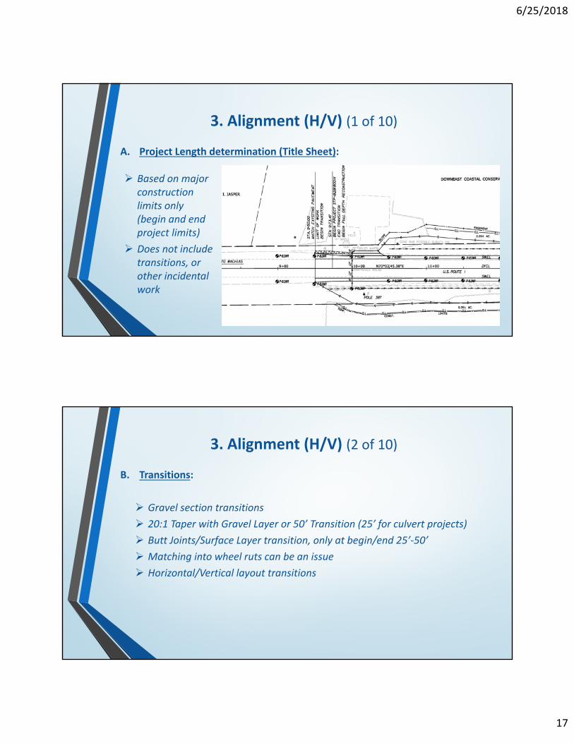
3. Alignment (H/V) (1 of 10)
A. Project Length determination (Title Sheet):
Based on major construction limits only (begin and end project limits)
Does not include transitions, or other incidental work
3. Alignment (H/V) (2 of 10)
B. Transitions:
Gravel section transitions
20:1 Taper with Gravel Layer or 50’ Transition (25’ for culvert projects)
Butt Joints/Surface Layer transition, only at begin/end 25’‐50’
Matching into wheel ruts can be an issue
Horizontal/Vertical layout transitions

6/25/2018
18
3. Alignment (H/V) (3 of 10)
C. Superelevation:
EI‐C20 (Superelevation Rate) references use of AASHTO for determination of Superelevation rate
Use MaineDOT HDG or AASHTO for Superelevation transitions
3. Alignment (H/V) (4 of 10)
C. Superelevation:
Super Transition Rule of thumb – max. of 2% in 50’
Could also use AASHTO for max. relative gradient(need to provide explanation)

6/25/2018
19
3. Alignment (H/V) (5 of 10)
C. Superelevation:
Design Guidance for “High Side Shoulder Rollover” transition
Transition from normal shoulder cross slope of ‐4% to ‐2% must be completed as the superelevated section reaches +4%
3. Alignment (H/V) (6 of 10)
D. Vertical Design:
Consider matching steeper grades on projects where matching back to existing conditions, to reduce work limits.
PI Bypass example: lowered fill amount required at southerly limit, by reducing freeway standards with Design Exception for vertical grade.

6/25/2018
20
3. Alignment (H/V) (7 of 10)
3. Alignment (H/V) (8 of 10)

6/25/2018
21
3. Alignment (H/V) (9 of 10)
E. Pavement Rehab options:
Type of treatment could affect the vertical alignment
Need to consider (fluff) inflation on rehabs (spline fit profiles okay)
Timing of when changes are brought to the Team (i.e., if type of treatment changes at or beyond PIC…and this affects the vertical profile…that is much more significant than having it change at HVAC)
“Selecting Rehab Options” Memo/Guidance coming soon
3. Alignment (H/V) (10 of 10)
F. Vertical Design:
Preference to NOT use angle points in profiles at the match point for side roads – try to limit this work to 50’‐100’
Expectations and potential project limitations
Existing side road Superelevation can sometimes play a role in extending project limits beyond the profile match point for a smooth transition.
DOT may provide additional guidelines Follow up with Highway Program (PM, Reviewer, etc.) prior to submission

6/25/2018
22
Alignment (Horizontal/Vertical)
Any Additional Questions or Comments?
Geometric Layout

6/25/2018
23
4. Geometric Layout (1 of 17)
A. Construction Notes Sheets vs. Notes on Plan sheets
Notes on Plan Sheets
4. Geometric Layout (2 of 17)
A. Construction Notes Sheets vs. Notes on Plan sheets
Separate Notes Sheets preferred

6/25/2018
24
4. Geometric Layout (3 of 17)
B. Tapers:
Taper Rates based on standard formulas –see EI‐C15 Guideline on Medians and Islands
40 mph and under WS2/60 and
45 mph and above WS where W is the width of the shift and S is the posted speed
Straight line tapers vs. reverse curves (Left‐turn tapers)
Case by case basis
4. Geometric Layout (4 of 17)
C. Lateral Offset to objects behind curb:
1.5’ behind face of curb is allowed for traffic signals, utility poles, etc.
If Utility Rules are met, DE not required
Check Clear Zone guidance in EI‐C2.1 Clear Zone (Design Guidelines)

6/25/2018
25
D. Minimum Curb length (granite); Spec Book and Standard Detail
Curb lengths are not discussed in the HDG.
Curb lengths are discussed in the standard specifications (Division 700 Materials, 712.04) ‐ 4’ minimum length for Type 1 curb
Curb lengths are discussed in the standard details – 609(01)
4. Geometric Layout (5 of 17)
D. Minimum Curb length (granite); Spec Book and Standard Detail
4. Geometric Layout (6 of 17)

6/25/2018
26
4. Geometric Layout (7 of 17)
E. Lane and Shoulder widths:
Road Diets ‐ narrower lane widths and less lanes could provide more width for multimodal activities (See Road Diet Guidelines)
E. Lane and Shoulder widths:
Update Coming Soon
Start with Engineering Instruction C2 – Bridge and Roadway Widths
4. Geometric Layout (8 of 17)
6/25/2018
27
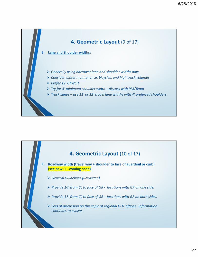
4. Geometric Layout (9 of 17)
E. Lane and Shoulder widths:
Generally using narrower lane and shoulder widths now
Consider winter maintenance, bicycles, and high truck volumes
Prefer 12’ CTWLTL
Try for 4’ minimum shoulder width – discuss with PM/Team
Truck Lanes – use 11’ or 12’ travel lane widths with 4’ preferred shoulders
F. Roadway width (travel way + shoulder to face of guardrail or curb) (see new EI…coming soon)
General Guidelines (unwritten)
Provide 16’ from CL to face of GR ‐ locations with GR on one side.
Provide 17’ from CL to face of GR – locations with GR on both sides.
Lots of discussion on this topic at regional DOT offices. Information continues to evolve.
4. Geometric Layout (10 of 17)
6/25/2018
28
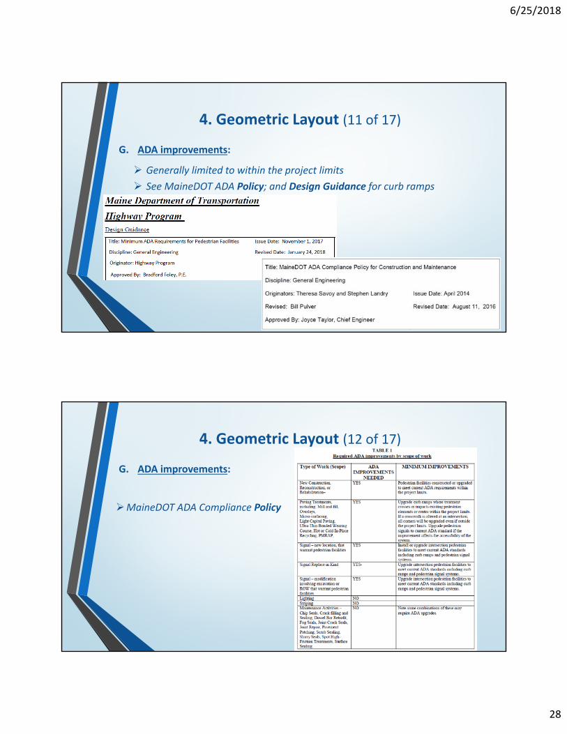
4. Geometric Layout (11 of 17)
G. ADA improvements:
Generally limited to within the project limits
See MaineDOT ADA Policy; and Design Guidance for curb ramps
4. Geometric Layout (12 of 17)
MaineDOT ADA Compliance Policy
G. ADA improvements:
6/25/2018
29
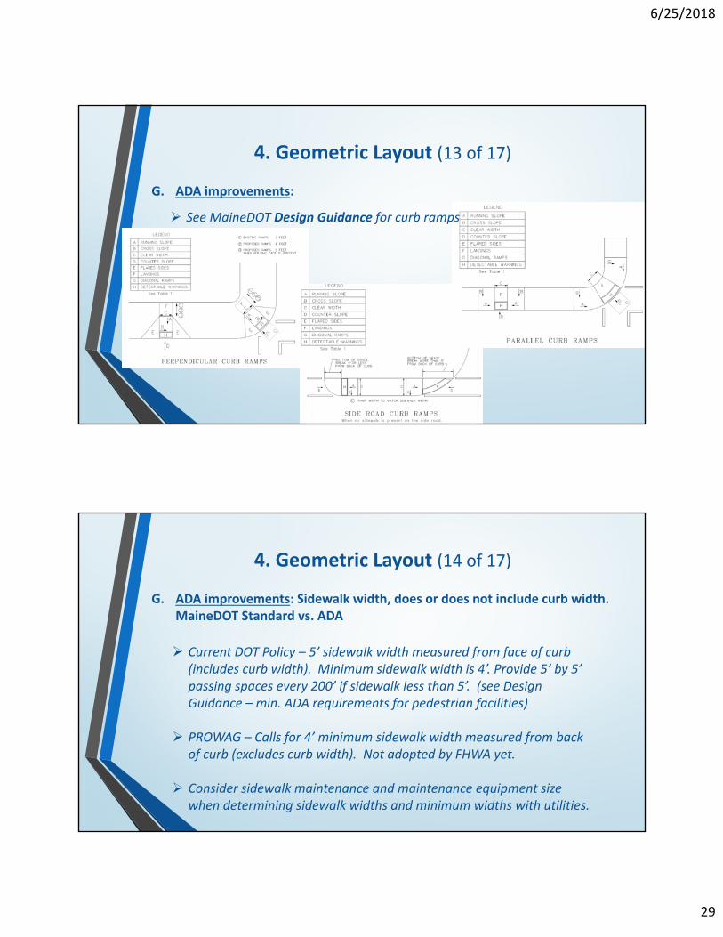
4. Geometric Layout (13 of 17)
G. ADA improvements:
See MaineDOT Design Guidance for curb ramps
G. ADA improvements: Sidewalk width, does or does not include curb width. MaineDOT Standard vs. ADA
Current DOT Policy – 5’ sidewalk width measured from face of curb (includes curb width). Minimum sidewalk width is 4’. Provide 5’ by 5’ passing spaces every 200’ if sidewalk less than 5’. (see Design Guidance – min. ADA requirements for pedestrian facilities)
PROWAG – Calls for 4’ minimum sidewalk width measured from back of curb (excludes curb width). Not adopted by FHWA yet.
Consider sidewalk maintenance and maintenance equipment size when determining sidewalk widths and minimum widths with utilities.
4. Geometric Layout (14 of 17)

6/25/2018
30
G. ADA improvements: Sidewalk width, does or does not include curb width. MaineDOT Standard vs. ADA (See MaineDOT ADA Design Guidance for Pedestrian Facilities)
4. Geometric Layout (15 of 17)
G. ADA improvements: Retrofit scenarios
Room for interpretation.
Balance of pedestrian desire lines and separated crosswalks.
Sidewalk widths 5’ preferred, 4’ desirable, 3’ minimum
Curb is included within the sidewalk width (per MaineDOT)
Technical Infeasibility (form to be filled out)
4. Geometric Layout (16 of 17)

6/25/2018
31
4. Geometric Layout (17 of 17)
Geometric Layout
Any Additional Questions or Comments?

6/25/2018
32
Drainage
5. Drainage (1 of 17)
A. Drainage analysis and pipe sizing completed by MaineDOT or by consultant; varies by project.
Confirm up front

6/25/2018
33
5. Drainage (2 of 17)
B. All drainage pipes crossing side roads should be Opt III or RCP, not underdrain…please confirm.
UD is okay, confirm with PM and Reviewer
5. Drainage (3 of 17)
C. Underdrain pipe runs from 12” to 30” can be designed to curve with the roadway. Maximum deflection angle, up to 10 degrees per pipe section along curve (confirm with pipe manufacturer specifications). Need to confirm when to have pipe follow curved curb line and when to show straight line pipe connection.
Show along curb line where possible If UD cannot follow curb then consider alternatives, i.e., extend subbase Straight line pipe may have ROW impacts

6/25/2018
34
5. Drainage (4 of 17)
D. Consider extending roadway subbase materials further out to eliminate conflicts between proposed UD and existing or proposed utilities, possibly in sharper radius curves also.
UD could also be moved into the roadway to avoid conflicts, subbase needs to grade towards UD location.
Coordinate with Team and Utilities before designing around utilities.
5. Drainage (5 of 17)
E. Shallow pipes still use 8’ CB; show sumps deeper than 2’ if basin could be less than 8’?
Details show 4’ cone, could call for 2’ offset cone or flat top with appropriate notes

6/25/2018
35
5. Drainage (6 of 17)
F. F‐Basins used in roadway?
Not preferred Can be used in the shoulder Use F5 min. for frost
5. Drainage (7 of 17)
G. Cross culvert sizing: 18” min. or location specific? Could be smaller, i.e. on side roads. Closed system could also be < 18”?
Yes to both

6/25/2018
36
5. Drainage (8 of 17)
H. Drainage Structure Type ‐ MH vs. CB B1 w/solid cover
Manhole & Catch Basin definitions CB B1 w/solid cover is preferred wording,
check wording in specification
5. Drainage (9 of 17)
I. 3” drop for pipes at CB vs. matching crowns (top of pipes)
Both are okay Try to avoid “Nesting Pipes”

6/25/2018
37
5. Drainage (10 of 17)
J. Pipe Ties:
Use on RCP only. Last two joints shall be tied. Shallow cover or other site specific conditions. Pipe ties used for all extensions.
5. Drainage (11 of 17)
K. Culvert ends > 36” on 3:1 slopes, considered a hazard?
36” and below not a hazard; no beveled ends
6/25/2018
38
5. Drainage (12 of 17)
L. Riprap driveway ends; Riprap downspouts at end of curb run.
Riprap at driveway ends: Not required unless needed for grade or stream
Riprap Downspouts: Only if needed/ based on conditions
5. Drainage (13 of 17)
M. Consideration of “snow basins”; CB at low point in non‐curbed areas.
Possible use in high snow areas; Aroostook County, Western Maine(confirm with PM)

6/25/2018
39
5. Drainage (14 of 17)
N. Design of RCP pipes is rounded to 8’ lengths for design. To avoid the need to cut to shorter lengths in the field.
4’ sections are okay to use but need a note that states why you need to use it and the 4’ section should be placed in the middle third of the pipe.
Must be precast 4’ section (not cut in field).
Consider Maintenance of Traffic needs when determining pipe lengths.
5. Drainage (15 of 17)
O. In long stretches of open ditch roads (i.e., PI Bypass), consider adding more, smaller culvert crossings to minimize major culvert crossings ultimately reducing the size of culverts at low points in watersheds.
Within reason

6/25/2018
40
5. Drainage (16 of 17)
P. Large Culvert Designs: Fish passage or wildlife crossing expectations. Box Culvert embedment generally required, fill material varies.
Work in progress, changes coming from ENV, trying to replicate the existing stream bed
Habitat Connectivity Training
5. Drainage (17 of 17)
Q. Any max length of UD run?
No, based on hydraulic review
6/25/2018
41
Drainage
Any Additional Questions or Comments?
Next Steps

6/25/2018
42
• Conduct Session 2…
• Document input/feedback received during these sessions.
• Update the list of topics
• Include additional questions/clarifications
• Confirm answers with MaineDOT
• Provide updated document to all GCA consultants and make available on MaineDOT Highway Design web page.
Next Steps
Questions
Send any additional questions or comments to:Tony Grande at [email protected] (207) 889‐3115