Project: IEEE P802.15 Working Group for Wireless Personal ...
32
doc.: IEEE 11-11-1277-00-0000 Submission September 2011 Hajime Furusawa, (JUTA) Slide 1 Slide 1 Project: IEEE P802.15 Working Group for Wireless Personal Area Networks (WPANs) Submission Title: What Japan Utility Telemetering Association (JUTA) has done and will do on the next-generation gas metering system in Japan Date Submitted: September 2011 Source: Hajime Furusawa, Japan Utility Telemetering Association (JUTA) Contact: Hajime Furusawa, Tokyo Gas Voice: +81-3-5604-8008, E-Mail: [email protected] Abstract: Smart Metering in Japan Purpose: Tutorial Session Notice: This document has been prepared to assist the IEEE P802.15. It is offered as a basis for discussion and is not binding on the contributing individual(s) or organization(s). The material in this document is subject to change in form and content after further study. The contributor(s) reserve(s) the right to add, amend or withdraw material contained herein. Release: The contributor acknowledges and accepts that this contribution becomes the property of IEEE and may be made publicly available by P802.15.
Transcript of Project: IEEE P802.15 Working Group for Wireless Personal ...

doc.: IEEE 11-11-1277-00-0000
Submission
September 2011
Hajime Furusawa, (JUTA) Slide 1 Slide 1
Project: IEEE P802.15 Working Group for Wireless Personal Area Networks (WPANs)
Submission Title: What Japan Utility Telemetering Association (JUTA) has
done and will do on the next-generation gas metering system in Japan Date Submitted: September 2011 Source: Hajime Furusawa, Japan Utility Telemetering Association (JUTA) Contact: Hajime Furusawa, Tokyo Gas Voice: +81-3-5604-8008, E-Mail: [email protected] Abstract: Smart Metering in Japan Purpose: Tutorial Session Notice: This document has been prepared to assist the IEEE P802.15. It is offered
as a basis for discussion and is not binding on the contributing individual(s) or organization(s). The material in this document is subject to change in form and content after further study. The contributor(s) reserve(s) the right to add, amend or withdraw material contained herein.
Release: The contributor acknowledges and accepts that this contribution becomes the property of IEEE and may be made publicly available by P802.15.

doc.: IEEE 11-11-1277-00-0000
What Japan Utility Telemetering Association (JUTA) has done and will do on the next-generation gas metering system in Japan
September 19, 2011
Hajime Furusawa Director
Japan Utility Telemetering Association,
Non-Profit Organization in Japan

Japan Utility Telemetering Association, Non-Profit Organization
doc.: IEEE 11-11-1277-00-0000
Profile of Japan Utility Telemetering Association
Mission To contribute to the realization of low carbon society
through the dissemination of modern utility telemetering system, which leads to the visualization of consumption of utilities
To contribute to the prevention of the occurrence of accidents as well as assurance of consumer’s safety and security through the dissemination of modern utility telemetering system
To assure the safety and security of aged citizens living alone through the modern telemetering system
To contribute to the improvement of productivity and efficiency of business through the dissemination of modern utility telemetering system
3

Japan Utility Telemetering Association, Non-Profit Organization
doc.: IEEE 11-11-1277-00-0000
Profile of Japan Utility Telemetering Association
History Founded as Japan LP Gas OA Association in
April, 1994 Changed the name to LP Gas IT Association in
June, 2003 Changed the name to Japan Utility
Telemetering Association in February, 2010
Member enterprises Total number: Over 70
4

Japan Utility Telemetering Association, Non-Profit Organization
doc.: IEEE 11-11-1277-00-0000
Initiatives of Japan Utility Telemetering Association Standardization of specifications of common
telemetering infrastructures Promotion of “ Mimamori service “,Keeping-
watch service for aged citizen living alone
Conducting the contract projects for governments Ministry of Internal Affairs and
Communications (2010) Agency of Natural Resources and Energy
(2003 and 2004)
5

Japan Utility Telemetering Association, Non-Profit Organization
doc.: IEEE 11-11-1277-00-0000
Dissemination of Telemetering System in Japan
Automatic meter-reading introduced in
1987 Dissemination level at present LP Gas: 6 millions (24%) City gas: 2 millions (7%) Water: 100,000
6

Japan Utility Telemetering Association, Non-Profit Organization
doc.: IEEE 11-11-1277-00-0000
Distinctive Situations for Telemetering in Japan
Use of customer’s telephone line
Two-way communication system
Customers’ demand for multi-services including “monitoring of occurrence of any abnormality” and “remote shut-off”
Battery-driven transceiver for more than 10years
7

Japan Utility Telemetering Association, Non-Profit Organization
doc.: IEEE 11-11-1277-00-0000
Introductions of smart gas meters in Japan
“Micom Meter” = Micro Computer controlled gas Meter
With microcomputer (City gas 1983-, LP gas 1985-)
One-way shut-off valve, Pressure switch, Seismic sensor
With communication function (City gas 1987-, LP gas 1988-)
AMR, Paid services Tow-way shut-off valve,
Pressure sensor, etc.
Ultra sonic gas meter (City gas 2005-, LP gas 2009-)
Measuring instantaneous flow rate Standard specification for City and LP gas.
City gas
LP gas

Japan Utility Telemetering Association, Non-Profit Organization
doc.: IEEE 11-11-1277-00-0000
Basic System of Present Telemetering system
Stationary communication
network (PSTN, etc )
Cable NCU※
Safety device
Wireless communication
network (Mobile phone network, etc )
Transceiver
Gas meter
Short range transceiver
Portable transceiver, etc
(Legend )
Detached house
Gas suppliers, etc Monitoring
Center
Transceiver NCU※
※NCU: Network Control Unit
(※) Both cable and wireless types are applicable to both detached house and apartment.
Apartment
9

Japan Utility Telemetering Association, Non-Profit Organization
doc.: IEEE 11-11-1277-00-0000
Problems of Telemetering System in Japan
Customer’s communication infrastrucure Decrease of analog telephone lines and diversification
of them (shift to IP and broadband)
Increase in customer’s demand for multi-services: Visualization of energy consumption Security and safety Mimamori service, etc
Increase in security-oriented housing that makes meter-reading by a metering person difficult Apartments with auto lock system Houses protected with a sophisticated security
system
10
Japan Utility Telemetering Association, Non-Profit Organization
doc.: IEEE 11-11-1277-00-0000
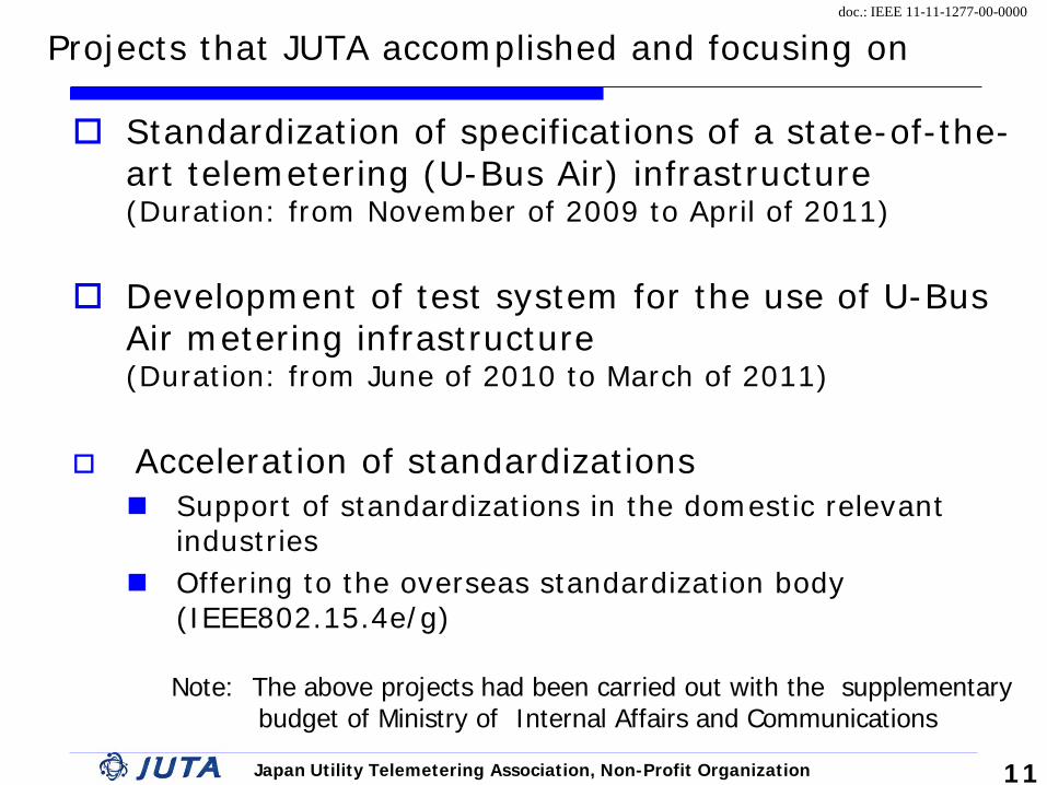
Projects that JUTA accomplished and focusing on
Standardization of specifications of a state-of-the-art telemetering (U-Bus Air) infrastructure (Duration: from November of 2009 to April of 2011)
Development of test system for the use of U-Bus Air metering infrastructure (Duration: from June of 2010 to March of 2011)
Acceleration of standardizations Support of standardizations in the domestic relevant
industries Offering to the overseas standardization body
(IEEE802.15.4e/g)
11
Note: The above projects had been carried out with the supplementary budget of Ministry of Internal Affairs and Communications

Japan Utility Telemetering Association, Non-Profit Organization
doc.: IEEE 11-11-1277-00-0000
Newly-Developed U-Bus Air Metering System
U-Bus Air metering system consists of only battery-driven meters, devices and transceivers Specifications of U-Bus (Common communication interface),
each NCU (Applicable to various access networks) and U-Bus Air (Short range transceiver) have been standardized already.
U-Bus Air is a core component in U-Bus Air metering system.
12
Apartment
Detached house
Inside of house
3.New-type of transceiver (U-Bus Air)
2. New-type of NCU
Gas meter
Water meter
Operation kit
Base Station
Center
1.New-type of interface (U-Bus)

Japan Utility Telemetering Association, Non-Profit Organization
doc.: IEEE 11-11-1277-00-0000
U-Bus Air What is the U-Bus Air ?
A new-type of 950 MHz-band transceiver※ that enables multi-hopping communication and the drastic reduction in consumption of electric power for communication
The PHY specs is based on IEEE 802.15.4g Draft, and the MAC uses RIT Mode written in IEEE 802.15.4e Draft of Low Energy.
Benefits and Advantages Its self- network function makes the installation simple and easy Its self- selection-function can provide customers with the
higher reliability
<An example of communication among meters in an apartment > ※ To be scheduled to shift to 920 MHz-band
Apartment

Japan Utility Telemetering Association, Non-Profit Organization
doc.: IEEE 11-11-1277-00-0000
Specifications of U-Bus Air
Items Specifications Specification of
transceiver ( ARIB STD-T96 )
Frequency :950MHz(*) Output :1mW/10mW Transmission velocity:100kbps
Network Max. 50 (Mesh type) Max. 240 (Cluster tree type)
Connections of NCU Max. 5 per network
Hopping Max. 15 per network
Theoretical network 17 millions
Packet size 100 bytes
Operating mode Intermittent operation: 3 seconds (Standard)
Interface U-Bus
Setup Self-registration and self-elimination
14 ※To be scheduled to shift to 920MHz-band

Japan Utility Telemetering Association, Non-Profit Organization
doc.: IEEE 11-11-1277-00-0000
Features of U-Bus Air(1) Asynchronous access
① All the transceivers operate intermittently. ② Short-packet transmission and short-time reception
are repeated periodically ③ Source of packet transfer continues reception for a
beacon ④ Link is set up between source of transfer and
destination of transfer on receiving beacon
Formation of link
Packet transfer Continuation of reception for a beacon
Source of transfer
Destination of transfer
Short-time reception
Intermittent operation
①
② ③ ④
Average electric power consumption is lower. Time
Start of transfer
15

Japan Utility Telemetering Association, Non-Profit Organization
doc.: IEEE 11-11-1277-00-0000
Features of U-Bus Air (2)
Exceptional reliability of communication ① Transferring to the transceiver which is closed to the
terminating destination in order of link formation)
② Detouring obstacle since the appropriate destination of transfer can be selected from multiple destinations of transfer
5
16
1
75 6
8
2 3 4
①
×
①
②
1
2
3
4
5
7
6
8
②
Source of transmission
Obstacle
Destination of transmission
Obstacle
Timing of beacon transmission
Time
First hopping
Second hopping

Japan Utility Telemetering Association, Non-Profit Organization
doc.: IEEE 11-11-1277-00-0000
Features of U-Bus Air(3) Effectively-use of the routs
① Distance vector table for every destination is compiled by exchanging with the neighboring one
② Every routing table is determined in comparison with the neighboring one
③ Packet is transferred to the neighboring transceiver that is toward the forward-directed position to the destination
Distance vector table Routing table
Destination
Packet addressed to E is transferred to neighboring B that is toward the forward-direction
Distance vector table is exchanged when the neighboring one is detected
②
BB CCAA -- --BB FF BBCC BB FFDD FF FF
EE FF FF
BB CCAA -- --BB FF BBCC BB FFDD FF FF
EE FF FF
AA 00
BB 11
CC 11
DD 22
EE 33
AA 00
BB 11
CC 11
DD 22
EE 33
17
Neighbor
A
B
D
C
③
A 3 B 2 C 2 D 1 E 0
A 2 B 1 C 1 D 0 E 1
E
+1
Distance vector table
① Note: F: Front B: Back

Japan Utility Telemetering Association, Non-Profit Organization
doc.: IEEE 11-11-1277-00-0000
Test System for U-Bus Air Metering Infrastructure
Test system has been developed for the users to be able to introduce the devices necessary for U-Bus Air metering system without anxiety. Interconnectivity testing system (Test Bed)
Connectivity between devices made by different makers is tested. ① Physical layer of transceiver ② MAC layer and NET layer
Operation simulator
Various performances are assessed under the practical environment
① Delayed time in communication ② Battery life of U-Bus Air
18

Japan Utility Telemetering Association, Non-Profit Organization
doc.: IEEE 11-11-1277-00-0000
Test Bed ( Interconnectivity test system )
:Transceiverunder subject of test
U-Bus tester
DUT GM
④ Measurement
Unit for the physical layer of transceiver
Filter
Sealed box
② ③ ③
Attenuator
Test bed is composed of each measuring unit and automatic test program
① Test bed platform: Input of information on test, Output of test results ② U-Bus tester: Test for U-Bus (Cable) ③ GM: Verification of communication procedure for U-Bus Air ④ Measurement Unit for the physical layer of transceiver: Measurement
of radio wave of U-Bus Air
①Test bed platform
GM
Divider
DUT
GM :Golden Master (Reference transceiver)
19
Attenuator

Japan Utility Telemetering Association, Non-Profit Organization
doc.: IEEE 11-11-1277-00-0000
Outlook of the Test Bed
④Measurement Unit for physical layer of transceiver
①Test bed platform
Sealed box for ③GM
Sealed box for
DUT
20

Japan Utility Telemetering Association, Non-Profit Organization
doc.: IEEE 11-11-1277-00-0000
Measurement of Physical Layer of Transceiver
Test Items Specifications
Quality of wave
Frequency 950MHz band (※)
Occupied bandwidth 400kHz
Output 10mW
Unwanted wave
Out-of-band emission ‐55dBm/100kHz
Leakage wave to neighboring channel ‐26dBm/100kHz
Emission wave in a state of reception ‐55dBm/100kHz
Radio function
Continuous transmission time at maximum/Quiescent time at minimum
100/100
Confirmation of function not to emit any waves by itself when there is other wave
-75dBm
Reception performance
Response -90dBm PER=1% or less
Transmission performance
Degree of modulation, etc by observation of waveform
GFSK(BT=0.5) 100%
21
※To be scheduled to shifted 920MHz band

Japan Utility Telemetering Association, Non-Profit Organization
doc.: IEEE 11-11-1277-00-0000
Measurement of MAC Layer and NET Layer
Measurement Items Details of measurements
MAC layer
Intermittent operation
Intermittent operation period 3 seconds (Example)
Measurement of reception time after intermitting 2ms
Transfer of neighboring data
Normal/Abnormal sequences Procedure, frame composition, timing
Quiescent time 100ms or more
Transfer of division data Normal/Abnormal sequences Procedure, frame composition,
timing
Data exchange Normal/Abnormal sequences Procedure, frame composition, timing
NET layer
Construction of network
Detection of neighboring transceiver ‐80dBm or more
Exchange of network information
Exchanging and editing of distance vector table
Transfer of data
Transmission/hopping/reception of data Function of multi-hopping
Treatment of abnormality Exceeding of time-limit for packet existence, etc
22

Japan Utility Telemetering Association, Non-Profit Organization
doc.: IEEE 11-11-1277-00-0000
Measurement of physical layer of transceiver (Occupied bandwidth )
Radio frequency spectrum (GFSK modulated wave )
Frequency bandwidth in which 99% of total electric power exists
Test Results of Physical Layer of Transceiver (Example)
23

Japan Utility Telemetering Association, Non-Profit Organization
doc.: IEEE 11-11-1277-00-0000
Operation simulator
U-Bus Air mesh network
Operation Simulator
24
Simulation under the practical environment Simulation tests Parameters (Input): Layout of U-Bus Air Devices,
Operation conditions, obstacle (attenuation), etc Comparison (Output): Communication delay time,
battery life, etc.

Japan Utility Telemetering Association, Non-Profit Organization
doc.: IEEE 11-11-1277-00-0000
Test Results of Operation Simulator (Example-1)
Influence of layout of NCU on communication delay time Average communication delay time is shorter in case
that NCU is laid out in the center while maximum one does not change
NCU
NCU laid out in the center
NCU laid out at the corner
Average delay time : 12 seconds
Maximum delay time : 27 seconds
25
Distribution of delay times
27 seconds
8 seconds
12 seconds
Average delay time : 8 seconds Maximum delay time : 27 seconds

Japan Utility Telemetering Association, Non-Profit Organization
doc.: IEEE 11-11-1277-00-0000
26
Battery life in network consisting of nine transceivers: 12.51 years
Battery life in network consisting of twenty five transceivers : 11.17years
Battery life in network consisting of forty nine transceivers: 10.41 years
Battery life of U-Bus Air transceiver in a detached houses area in the suburbs
Test Results of Operation Simulator (Example-2)
Relationship between network size and battery life Simulation was conducted on the condition that the frequency of
polling and call-out is one time per two weeks respectively Targeted battery life of ten years was attained even in case of the
largest network size of NCU

Japan Utility Telemetering Association, Non-Profit Organization
doc.: IEEE 11-11-1277-00-0000
Apartment used for test (10 households ×10 floors)
Multi-hopping transceiver
Internal of pipe-shaft
27
Field-test of U-Bus Air system Field-test for communication was carried out installing a
U-Bus Air in pipe-shaft of every house in the apartment.

Japan Utility Telemetering Association, Non-Profit Organization
doc.: IEEE 11-11-1277-00-0000
1F
2F
3F
4F 5F
6F
7F
8F
9F
10F
The eighth room
The sevent room
The sixth room
The fifth room
The fourth room Picture of apartment
Layout of U-Bus Air Transceivers in Field-test
28
Forty eight (48) U-Bus Air transceivers were installed in the layout of five (5) per floor×ten (10) floors Information on network composition of U-Bus Air was
obtained

Japan Utility Telemetering Association, Non-Profit Organization
doc.: IEEE 11-11-1277-00-0000
Results of Field-test of U-Bus Air (Example 1)
Whole U-Bus Air transceivers within the network could be connected each other with four-time hopping in case that NCU was installed on the top floor
29
one time hopping
10 9 8 7 6 tow-time hopping
three-time hopping
23 18 15 14 11 four-time hopping
28 26 25 24 5
35 33 32 31 30
41 39 38 37 36
46 45 44 43 42
52 50 49 48 47
57 56 55 54 53
69 67 64 59 58
74 72 70
R10 R9 R8 R7 R6 R5 R4 R3 R2 R1
10 F
9F
8F
7F
2F
1F
6F
5F
4F
3F
描画
消去
Note: F: Floor R: Room

Japan Utility Telemetering Association, Non-Profit Organization
doc.: IEEE 11-11-1277-00-0000
Results of Field-test of U-Bus Air (Example 2)
Whole U-Bus Air transceivers within the network were perfectly connected each other with three-time hopping in case that NCU was installed on the middle floor (Fifth floor)
One-time hopping
10 9 8 7 6 Two-time hopping
Tree-time hopping
23 18 15 14 11 Four-time hopping
28 26 25 24 5
35 33 32 31 30
41 39 38 37 36
46 45 44 43 42
52 50 49 48 47
57 56 55 54 53
69 67 64 59 58
74 72 70
R10 R9 R8 R7 R6 R5 R4 R3 R2 R1
10 F
9F
8F
7F
2F
1F
6F
5F
4F
3F
描画
消去
30
Note: F: Floor R: Room

Japan Utility Telemetering Association, Non-Profit Organization
doc.: IEEE 11-11-1277-00-0000
Acknowledgement
A state-of-the-art telemetering infrastructure has just been development by Japan Utility Telemetering Association.
We, at JUTA, are ready to offer this technology not only to the domestic users but also to the overseas ones, because we are very much confident that this next generation- type system could without doubt contribute to the realization of Smart Meter Systems and Home Energy Management Systems.
We would like you to visit the exhibition corner
where you will be able to understand our system in more detail.
31

Japan Utility Telemetering Association, Non-Profit Organization
doc.: IEEE 11-11-1277-00-0000
Thank you so much for your attention