Project: High Court of Australia Security Control Room ...
100
2573-SP1/D Issue Date: 19.09.2019 Issue : FOR TENDER Page 1 of 100 Project: High Court of Australia Security Control Room & Secure Lift Foyer Preliminaries & Architectural Technical Specification 2573-SP1/D Prepared by: Integrated Space Pty Ltd PO Box 5144 Kingston ACT 2604 T: 02 6273 0805 F: 02 6273 0806 E: [email protected] Primary Nominee: Sergio Garcia Registration No. 771 Version 1.0
Transcript of Project: High Court of Australia Security Control Room ...

2573-SP1/D
Issue Date: 19.09.2019 Issue : FOR TENDER Page 1 of 100
Project:
High Court of Australia
Security Control Room & Secure Lift Foyer
Preliminaries & Architectural Technical Specification 2573-SP1/D Prepared by:
Integrated Space Pty Ltd
PO Box 5144
Kingston ACT 2604
T: 02 6273 0805
F: 02 6273 0806
Primary Nominee: Sergio Garcia
Registration No. 771
Version 1.0

2573-SP1/D
Issue Date: 19.09.2019 Issue : FOR TENDER Page 2 of 100
TABLE OF CONTENTS
0131 PRELIMINARIES ........................................................................................................................... 4
0161 QUALITY ...................................................................................................................................... 16
0171 GENERAL REQUIREMENTS ...................................................................................................... 17
0181 ADHESIVES, SEALANTS AND FASTENERS ........................................................................... 25
0182 FIRE-STOPPING .......................................................................................................................... 30
0183 METALS AND PREFINISHES ..................................................................................................... 34
0401 DEMOLITION ............................................................................................................................... 37
0453 DOORS AND HATCHES ............................................................................................................. 41
0455 DOOR HARDWARE .................................................................................................................... 46
0511 LININGS ....................................................................................................................................... 49
0521 PARTITIONS – SYSTEMS .......................................................................................................... 53
0524 GLAZING ..................................................................................................................................... 59
0551 JOINERY ...................................................................................................................................... 62
0552 METALWORK .............................................................................................................................. 68
0560 TILING .......................................................................................................................................... 71
0590 ELECTRIC DOOR OPERATOR .................................................................................................. 78
0640 FIRE RATED CURTAIN ............................................................................................................... 80
0651 RESILIENT FINISHES ................................................................................................................. 86
0671 PAINTING & OTHER FINISHES ................................................................................................. 91
ATTACHMENT 1 – DOOR SCHEDULE ............................................................................................... 98
ATTACHMENT 2 – SAMPLE TABLE ................................................................................................ 100
Revisions
Revision No. Date Revision Approved Authorised for Issue
A 03.07.19 Tender issue SG
B 29.08.19 Amended Tender issue PH
C 19.09.19 Revised Tender issue PH
D 05.11.19 Tender issue SG

2573-SP1/D
Issue Date: 19.09.2019 Issue : FOR TENDER Page 3 of 100
1.1 CONFIDENTIAL INFORMATION
This document is made available to the recipient on the express understanding that the information contained in it be regarded and treated by the recipient as strictly confidential. The contents of this document are intended only for the sole use of the recipient and should not be disclosed or made available to any other person.
1.2 DISCLAIMER OF LIABILITY
The information contained in this document is provided for the sole use of the recipient and no reliance should be placed on the information by any other person. In the event that the information is disclosed or made available to any other person, Integrated Space P/L accepts no liability for any loss or damage incurred by that person whatsoever as a result of using the information.
1.3 COPYRIGHT ©
All rights reserved. No part of the content of this document may be reproduced, published, transmitted or adapted in any form or by any means without the express written permission of Integrated Space P/L.
1.4 TECHNICAL STANDARDS
The tender documents are to be read as a holistic set of documents. This includes all drawings and specifications, both architectural and engineering disciplines. If there is a conflicting requirement between any of the separate documents (drawings and specifications), the higher standard is to apply in all instances.
1.5 AUSTRALIAN STANDARDS
Where an Australian Standard is reference within the tender documents the latest version of that Standard is to apply in all instances.

2573-SP1/D
Issue Date: 19.09.2019 Issue : FOR TENDER Page 4 of 100
0131 PRELIMINARIES
1 GENERAL
1.1 GENERAL
1.1.1 Scope of Work The scope of the work includes all work required, as specified or implied, to carry out the works including the following:
Demolish partitions, bulkheads, joinery and the like as illustrated in the tender drawings Construction partitions/walls as illustrated in the tender drawings Construct door frames and hand doors with relevant hardware as illustrated in the tender drawings Install operable door as illustrated in the tender drawings Manufacture and install new joinery as illustrated in the tender drawings Install and finish new linings as illustrated in the tender drawings Install new fittings and fixtures as illustrated on the tender drawings Lift existing floor finishes illustrated on the tender drawings Lay new floor finishes as illustrated on the tender drawings Apply other finishes as illustrated in the tender drawings Undertake all mechanical, electrical, fire and security work as illustrated on the tender drawings Coordination of all the work between subcontractors and works undertaken by other persons
engaged directly by the Principal Provision of all builder’s works required to complete the services works as specified or implied Coordination of work with all subcontractors including those selected within this specification Making good as required to complete the works Final clean
All work shall be carried out in accordance with the Conditions of Contract, Specification and Drawings, which form part of this Contract.
The work includes the procurement and construction of building and services works to completion in the prescribed time frame and maintenance during the defect liability period, all to industry best practice, Building Code of Australia (edition current at time of tender), local authority requirements, current relevant Australian Standards, including amendments, and to the satisfaction of the Principals Representative.
All work and materials shall be in accordance with relevant manufacturer’s recommendations, accepted trade practice and as necessary for the satisfactory operation and completion of the works.
1.1.2 Schedule of Drawings and Documents The following documents, and subsequent revisions, form part of the scope of works:
Architectural drawings & specifications;
Document Number Title Date Revision
Architectural
2573 Cover Sheet – Ground Floor Security Control Room and Secure Lift Foyer
05.11.19
2573-A100 Location & Site Plan 05.11.19 A
2573-A101 Legend & Notes 05.11.19 A
2573-A102 Staging Plan 05.11.19 A
2573-A103 Existing & Cross Reference Plan 05.11.19 A
2573-A104 Proposed & Cross Reference Plan 05.11.19 A
2573-A105 Existing Plan Sheet 1 of 3 05.11.19 B
2573-A106 Existing Plan Sheet 2 of 3 05.11.19 A
2573-A107 Existing Plan Sheet 3 of 3 05.11.19 A
2573-A108 Proposed Plan Sheet 1 of 3 05.11.19 A

2573-SP1/D
Issue Date: 19.09.2019 Issue : FOR TENDER Page 5 of 100
2573-A109 Proposed Plan Sheet 2 of 3 05.11.19 E
2573-A110 Proposed Plan Sheet 3 of 3 05.11.19 A
2573-A111 Plan Detail of Sliding Door SD1 05.11.19 B
2573-A112 Existing Reflected Ceiling Plan 05.11.19 A
2573-A113 Proposed Reflected Ceiling Plan 05.11.19 A
2573-A114 Elevations and Sections Sheet 1 of 3 05.11.19 A
2573-A115 Elevations and Sections Sheet 2 of 3 05.11.19 A
2573-A116 Elevations and Sections Sheet 3 of 3 05.11.19 B
2573-A117 Partitions Types Sheet 1 of 4 05.11.19 B
2573-A118 Partitions Types Sheet 2 of 4 05.11.19 B
2573-A119 Partitions Types Sheet 3 of 4 05.11.19 A
2573-A120 Partitions Types Sheet 4 of 4 & Detail 05.11.19 B
2573-A121 Details Sheet 1 of 2 05.11.19 B
2573-A122 Details Sheet 2 of 2 05.11.19 A
2573-A123 Existing Floor Finishes Plan 05.11.19 A
2573-A124 Proposed Floor Finishes Plan 05.11.19 B
2573-A125 Proposed Finishes Plan 05.11.19 B
2573-P100 Existing & Cross Reference Plan for Photos 05.11.19 A
2573-P101 Existing Photos - Sheet 1 of 2 05.11.19 A
2573-P102 Existing Photos - Sheet 2 of 3 05.11.19 B
2573-J200 Joinery J01 Plan 05.11.19 C
2573-J201 Joinery J01 Elevations 05.11.19 B
2573-J202 Joinery J01 Sections & Details 05.11.19 B
2573-J203 Joinery J01 Section, Details & Finishes 05.11.19 B
2573-J204 Joinery J02 05.11.19 A
2573-J205 Joinery J03 05.11.19 A
2573-J206 Joinery J04 & J05 Plan & Finishes 05.11.19 B
2573-J207 Joinery J04 & J05 Elevations & Sections 05.11.19 A
2573-SP1 Preliminaries & Architectural Technical Specification
05.11.19 D
HCA-SCR-ND1 New Doors 13.05.19 A
HCA-SCR-PD1 Painting Schedule - Doors 13.05.19 A
HCA-SCR-PF1 Painting Schedule - Floor 13.05.19 A
HCA-SCR-PF2 Painting Schedule - Walls 13.05.19 A
HCA-SCR-PF3 Painting Schedule – Walls Elevations 13.05.19 A
For Information
HCA-MBP-GRA Amenities & Loading Dock 1.03.19 A
HCA-MBP-GRB Car Park & Loading Dock Entries 1.10.18 A

2573-SP1/D
Issue Date: 19.09.2019 Issue : FOR TENDER Page 6 of 100
Engineering Services;
Document Number Title Date Revision
Electrical
119109-E000 Cover Sheet – Electrical Services 29.03.19 A
119109-E001 Legend - Electrical Services 29.03.19 A
119109-E002 Scope Of Works - Electrical Services 29.03.19 A
119109-E300 Ground Floor - Existing Lighting Layout - Electrical Services
29.03.19 A
119109-E310 Ground Floor - New Lighting Layout - Electrical Services
29.03.19 A
119109-E311 Ground Floor - New Lighting Conduit Layout - Electrical Services
29.03.19 A
119109-E400 Ground Floor - Existing Power & Communications Layout - Electrical Services
29.03.19 A
119109-E405 Basement - New Power & Communications Layout - Electrical Services
29.03.19 A
119109-E410 Ground Floor - New Power & Communications Layout - Electrical Services
29.03.19 A
119109-E500 Existing Lighting Controls - Electrical Services 29.03.19 A
119109-E600 Single Line Diagram - Electrical Services 29.03.19 A
Mechanical
M1000 Cover sheet 19/02/2019 A
M1001 Legend 19/02/2019 A
M1002 Standard Details & Equipment Schedules 19/02/2019 A
M2000 Demolition Layout 19/02/2019 A
M2100 Air Conditioning and Ventilation Layout 19/02/2019 A
M6000 Control Schematic 19/02/2019 A
Section A. Preliminaries
177025 High Court of Australia New Security Centre. A. Preliminaries
19/02/2019 A
Section B. System Description - Mechanical
177025 High Court of Australia New Security Centre. B. System Description - Mechanical 19/02/2019 A
Section C. Material and Equipment - Mechanical
177025 High Court of Australia New Security Centre. C. Material and Equipment - Mechanical
19/02/2019 A
Section A. Preliminaries
177025 High Court of Australia New Security Centre. A. Preliminaries
22/02/2019 B
Section B. System Description – Mechanical
177025 High Court of Australia New Security Centre. B. System Description - Mechanical 22/02/2019 B
Fire
23-16518-F001 Cover Sheet & Drawing Index 03.04.2019 C
23-16518-F002 General Notes & Legend 05.04.2019 C
23-16518-F050 Fire Sprinkler Demolition Layout 05.04.2019 C
23-16518-F100 Proposed Fire Sprinkler Layout 08.04.2019 D
23-16518-F200 Proposed Fire Detection & EWIS Layout 10.05.2019 E
Security
SCG00839-SEC-SPC-0001
Electronic Security Services Systems Specification
24.04.19 0

2573-SP1/D
Issue Date: 19.09.2019 Issue : FOR TENDER Page 7 of 100
SCG00839-SEC-SCH-0001
Tender Schedules 24.04.19 0
SCG00839-SEC-DWG-0001
Security Cover Sheet, Drawing List and Legend
23.04.19 0
SCG00839-SEC-DWG-0100
Security Services Existing Ground Floor Plan 23.04.19 0
SCG00839-SEC-DWG-0110
Security Services New Ground Floor Plan 23.04.19 0
SCG00839-SEC-DWG-0111
Security Services Basement Floor Plan 08.05.19 1
SCG00839-SEC-DWG-0112
Security Services New Ground Floor Penetrations Plan
08.05.19 0
SCG00839-SEC-DWG-0700
Security Services Schematic 23.04.19 0
SCG00839-SEC-DWG-0800
Security Services Details Sheet 1 23.04.19 0
SCG00839-SEC-DWG-0801
Security Services Details Sheet 2 23.04.19 0
SCG00839-SEC-DWG-0802
Security Services Details Sheet 3 23.04.19 0
The following work (supply and installations of workstations) is not included under the tender and is to be carried out on site during the currency by the Principal. Documents for the work to be undertaken by the Principal are included in the tender documents for information only. Allow for relevant programming, management, attendance, liaison, coordination as required for these works.
Workstations
2573-WK001 Location & Site Plan 05.11.19 A
2573-WK100 Workstation Plan 05.11.19 A
2573-WK101 Workstation Elevations 05.11.19 A
2573-WK102 Workstation Sections 05.11.19 A
1.1.3 Building Work Include in the work all the drilling, bending, cutting, opening-up and the like necessary to complete the work including work associated with the engineering services including the installation of equipment to/or in the walls, ceilings, floors, partitions and the like.
Include in the work all openings, penetrations, cutting of holes, sealing of penetrations and holes, sleeves, etc. as required to complete the works including building work as required by the services trades.
Make good any damage including the repair and finishing of all surfaces and services work as specified. This includes painting, plastering, polishing of vinyl floors, replacement of damaged ceiling components, etc. to the satisfaction of the Superintendent.
Provide access openings to the ceiling space, including temporary removal of linings, suspension systems, steel structure and steel mesh, as required to carry out the works. Repair, patch and/or paint all access openings upon completion of the works.
Provide dust control measures to the satisfaction of the Superintendent where existing suspended ceiling tiles are to be removed.

2573-SP1/D
Issue Date: 19.09.2019 Issue : FOR TENDER Page 8 of 100
1.1.4 Stages The works are to be out carried in a series of stages. Each stage is to be completed and handed over to the Superintendent as outlined below.
Provide details of each stage in the construction programme. The following timeframes apply to the separable portions described below and illustrated on the tender drawings.
Perform the works in the following sequence and approximate time frames.
1: All works outlined in the Principal-supplied documents excluding those works to be undertaken under stages 2, 3 & 4. Commence the works within 1 week of acceptance of tender and complete within 6 weeks from the date of acceptance of tender
Stage 2: All works outlined in the Principal-supplied documents excluding those works to be undertaken under Stages 1, 3 & 4. Commence the works 1 week after the completion of 1 works and complete within 2 week of the commence date.
Stage 3: All works outlined in the Principal-supplied documents excluding those works to be undertaken under Stages 1, 2 & 4. Commence the works 2 days after the completion of Stage 2 works and complete within 3 weeks of the commence date
Stage 4: All works outlined in the Principal-supplied documents excluding those works to be undertaken under Stages 1, 2 & 3. Commence the works 1 day after the completion of Stage 3 works and complete within 3 weeks of the commence date
1.1.5 Work By Others and/or the Principal
The following work is not included under the tender and may be carried out on site during the currency of the Principal. Allow for relevant programming, management, attendance, liaison, coordination and the like for these works;
Supply and installation of workstations Bush hammering of render to concrete column as illustrated on drawing 2573-A121
1.1.6 Compliance All the work to be performed under the Contract is to comply with the latest edition of the Building Code of Australia/National Construction Code and relevant state supplements as well as the latest edition of all relevant Australian Standards as produced by the Standards Australia.
1.1.7 Measurement All measurements are to be checked on the site of the works and any dimensions indicated on the Drawings are to be considered nominal only. No scaling of Drawings is to take place during both the Tender and Contract Periods.
1.1.8 Workmanship and Materials Except where otherwise specified, all materials shall be new and the best of their respective kinds; all workmanship shall be executed in a first class and tradesman like manner and both materials and workmanship shall conform to the latest edition of the relevant standard of the Standards Association of Australia and the Building Code of Australia and relevant State and/or Territory supplements.
1.1.9 Joining Up Where the method of joining up old and new work is not otherwise specified, the cutting away and joining up shall be carried out in a manner approved by the Superintendent and made good in all trades to match existing adjacent work.
1.1.10 Evidence of Builders Licence Where an Act or Ordinance of the State or Territory in which the site of the works is located requires that a builder (as defined by the Act or Ordinance) be registered or licensed to carry out the work described in the tender documents, provide evidence that he is so registered or licensed. Submit a copy of the relevant license or registration with the tender submission.
1.1.11 Licences/Approvals and Certificate of Occupancy and Use If the legislation requires that a building certifier be engaged for the works then the Superintendent shall engage and separately pay for all costs associated with the engagement of a private certifier and approval of documentation.
All costs associated with the private certifier and Council approvals shall be paid for by the Superintendent.

2573-SP1/D
Issue Date: 19.09.2019 Issue : FOR TENDER Page 9 of 100
The Superintendent shall take out relevant building permits and pay for all costs associated with such permits.
Allow to obtain and provide all relevant certifications to all relevant Australian Standards as required from the glazing, mechanical, electrical, fire, hydraulic services subcontractors and the like and provide such certificates to the building certifier.
The Superintendent shall pay any relevant Construction Industry Training Levy as required.
1.1.12 Environmental Protection Observe and comply with all environmental requirements that apply to the area in which the work under the Contract is to be carried out.
Noise Control: Take all practicable precautions to minimise noise arising out of or resulting from any activity associated with the work under the Contract. All construction equipment shall be fitted with noise suppressors unless specially designed for quiet operation.
Site Control: Except as otherwise provided in the Contract, delivery of materials to the site and space storage of such materials will be allowed only in accordance with arrangements approved by the Superintendent and subject to such conditions as are determined by the Superintendent.
Disposal of Wastes and Refuse: Subject to conditions determined by the Superintendent, the Contractor shall be responsible for the proper disposal of all solid, liquid and gaseous wastes in accordance with all statutory requirements and in accordance with the National Codes of Practice and related Guidance Notes.
Refuse arising from the execution of work under the Contract (including food scrap and the like) must be removed from the site.
1.1.13 Precautions Unless otherwise specified in the Contract, observe, in the absence of any statutory requirement to the contrary, the relevant current Australian Standard published by the Standards Association of Australia relating to the storage, transport, use of materials, explosives, fire precautions in arc or flame cutting and flame heating and arc or gas welding operations, plant and equipment, work processes and safety precautions.
The Contractor shall not at any time use or cause to be used any explosives or arc or flame cutting or flame heating or arc or gas welding equipment without the approval of the Superintendent and shall ensure that proper precautions and proper care are taken in respect of such explosives or equipment.
1.1.14 Protection and Permits Protect all existing equipment, fixtures, fittings, joinery, wall, floor and ceiling surfaces, doors and the like, while executing the works required under the Contract. Any damage caused to any item, surface etc. shall be repaired to the satisfaction of the Superintendent at the Contractor’s expense.
1.1.15 Work to Take Place Out of Hours The following work shall be performed outside normal working hours and shall not be permitted at all during the High Court’s sittings dates as illustrated on the HCA Calendar of Sitting Dates:
All noisy works such as drilling into the concrete, grinding of floor slabs, core drilling or masonry/concrete saw cutting, concrete demolition and the like that reverberates through the building. Such work will only be permitted 6.00am to 8.00am. What constitutes noisy work shall be determined exclusively by the Superintendent’s Representative
All painting
Normal working hours are defined in Clause 1.1.17

2573-SP1/D
Issue Date: 19.09.2019 Issue : FOR TENDER Page 10 of 100
1.1.16 Work to Take Place During Normal Working Hours The following work shall be performed during normal working hours:
All the work except noisy work as described above
Normal working hours are defined in Clause 1.1.17
1.1.17 Normal Working Hours For the purposes of Clause 1.1 15 and 1.1.16, normal working hours are defined as Monday to Friday 7.00am to 10.00pm and Sunday 10.00am to 4.00pm with the exception of public holidays which shall be treated as out of hours. Any work outside these hours may be possible but only through prior application to and approval by the Superintendent.
1.1.18 Selected Subcontractors Nil
1.1.19 Provisional Sums Include in its tender price the following provisional sums. In the event of a Provisional Sum not being expended or being greater or less than the amount stated, then the amount of the difference shall be certified by the and shall be taken into account in determining the final Contract sum. Where any adjustment is made that adjustment shall not include any amount on account of profit or attendance on the part of the Contractor.
Provisional Sum Amount (exc. GST)
Nil $0.00
Total $0.00
1.1.20 Subcontracting General: Submit a complete list of proposed subcontractors and suppliers at the time of tender. The approved list shall form part of the Contract.
Purpose of submission: For approval
Do not subcontract any part of the Works to any subcontractor not listed in in the Contract without the prior written approval of the Superintendent. Such subcontracting shall not relieve the Contractor from any liability or obligation under the Contract.
1.1.21 Programme of work General: Submit a construction programme with the tender submission and a revised construction programme with 5 working days of the awarding of the contract.
Construction programme: Show the following:
Sequence of work Separable Portions (if any) Critical paths of activities related to the work Allowance for holidays Activity inter-relationships External dependencies including provision of access, document approvals and work by others Periods within which various stages or Portions of the work are to be executed Lead times for materials and specified items
Time scale: Working days.
Updated programme: Identify changes since the previous version and show the estimated percentage of completion for each item of work.
Programme chart: Display in the Contractor’s site office an up-to-date bar chart and network diagram based on the construction programme.
1.1.22 Site meetings General: Site meetings are to be held throughout the duration of the Contract on a weekly basis or at a frequency determined by mutual agreement between the Contractor and the Superintendent. The meetings are to be attended by the Superintendent, Contractor and relevant subcontractors.
Frequency: Weekly on site

2573-SP1/D
Issue Date: 19.09.2019 Issue : FOR TENDER Page 11 of 100
Minutes: The Contractor shall keep minutes of the meeting and provide copies to all relevant parties within 2 Working Days after each meeting.
1.1.23 Key Personnel General: At the first site meeting, submit a list of the names and telephone numbers of responsible persons who may be contacted after hours during the course of the Contract. Amend the list of names and telephone numbers as required and resubmit at each site meeting as part of the site meeting minutes.
Purpose of submission: Information only
1.1.24 Workplace Health and Safety Comply with all relevant Workplace Health and Safety regulations and legislation. The Contractor has a duty of care, which is to be strictly observed, towards the Contractor’s employees, subcontractors, selected subcontractors, on-site employees of the Principal and any person within the vicinity of the site of the works. Exercise due diligence when performing the work to ensure the safety of the Contractor’s employees, subcontractors, selected subcontractors, on-site employees of the Principal and any person within the vicinity of the site of the works to ensure safety is not compromised in any way
1.1.25 Site Induction Conduct the induction of all personnel including trades people, subcontractors, selected subcontractors, etc. prior to commencing work on-site. The induction process shall make reference to but not be limited to the following subjects:
Contractor’s site rules On-site safety Work method statements Hazardous substances Material safety data sheets Manual handling Use of scaffolding Use of power tools First aid Disciplinary action Protective clothing and equipment Site foreman Occupational health and safety requirements The Principal’s security requirements Contractors Site Terms and Conditions - Property Project Officer Jan 2018
1.1.26 Witness Hold Points A witness hold point means work cannot proceed the beyond such a point until the Superintendent has inspected the works and provided written confirmation that the inspection of the works has taken place, the works are found to be satisfactory and consistent with the requirements of the contract documents and work may progress beyond the hold point.
When the Contractor approaches or arrives at a witness/hold point he/she shall notify the Superintendent in writing that a specific witness/hold point is about to be arrived at or has been arrived at so that the Superintendent can undertake the necessary inspection. A minimum of 48 hours’ notice shall be provided to the Superintendent so the Superintendent can complete the necessary inspection of the works. Failure by the Contractor to notify the Superintendent with a minimum of 48 hours’ notice may result in delays to the works. Such delay and any costs arising from such delay shall be borne exclusively by the Contractor. The Superintendent shall undertake an inspection within 48 hours of being notified in writing that a witness/hold point has been arrived at. Should the Superintendent fail to undertake an inspection within 48 hours of receiving written notification, the Contractor may proceed with the work as documented.
Witness/hold points shall be clearly identified on the construction programme required to be prepared by the Tenderer/Contractor.
The following witness hold points apply to this project:
when partition framing for the SP4 partition type has been completed including fixing of 1mm thick steel sheet but before any plasterboard lining is fixed

2573-SP1/D
Issue Date: 19.09.2019 Issue : FOR TENDER Page 12 of 100
when partition framing for the SP4 partition type has been completed including fixing of plywood sheeting but before any plasterboard lining is fixed
when SP1 partition has had insulation glued to inner face of plasterboard and before the plasterboard is fixed to the support frame
1.1.27 Shop Drawings Shop drawings are required to be submitted for:
refer mechanical and electrical documents Shop drawings are to be submitted in duplicate to the Superintendent. Work is not to commence until “permission to use” status is granted by the Superintendent. A minimum of 4 working days shall be provided to the Superintendent for evaluation of the drawings in order to grant permission to use. Should drawings be rejected, the Contractor or relevant subcontractor shall amend the drawings as required and re-submit them for re-evaluation. A minimum of 4 working days shall be provided to the Superintendent for re-evaluation of the drawings in order to grant permission to use. This process shall continue until the Superintendent grants “permission to use” status to the drawings at which time work can then commence.
Any delays and/or costs associated with the preceding activities shall be borne by the Contractor and shall in no way affect the contractual completion date of the works.
1.1.28 Work Method Statements & Material Safety Data Sheets Upon acceptance of a Tenderer’s tender submission or quotation, the Contractor is to submit relevant Work Method Statements (WMS) and Material Safety Data Sheets (MSDS), covering all work required to take place and all products to be used to deliver the project, to the Superintendent. The Contractor, sub-contractors, selected subcontractors or suppliers are to ensure that the submitted WMS(s) and MSDS(s), comply with the requirements of the Workplace Health and Safety Act and other relevant local authorities. The Contractor, sub-contractors, selected sub-contractors or suppliers must identify, assess and manage the risks associated with works and implement measures to mitigate such risks. The Superintendent will not assess or approve any WMS(s) or MSDS(s) but simply record receipt of such documents and retain such documents for future reference as required.
The submission of WMS(s) and MSDS(s), shall not relieve the Contractor, sub-contractors, selected sub-contractors or suppliers from the responsibility to ensure that the WMS(s) and MSDS(s) accurately reflect the work required to take place to deliver the project and the manner in which the work is implemented. It is the Contractors, sub-contractors and selected sub-contractors’ responsibility to ensure that work practices on site, throughout the duration of the works, comply with all the requirements of the WMS(s) and MSDS(s).
WMS(s) and MSDS(s), are to be reviewed and updated from time to time by the Contractor, sub-contractors, selected sub-contractors or suppliers to reflect requirements which may change throughout the duration of a project and ensure relevant control measures are revised as required.
Failure to comply with the requirements of this clause may result in the Superintendent taking action under the Contract provisions to cancel the Contract.
1.1.29 Dilapidation Report The Contractor is to prepare a dilapidation report of the site of works before any work commences on site. Photographs may or may not be allowed to be taken in the site of works. The Superintendent is to be consulted to establish whether photographs may be taken. The report is to record in detail the condition of the site of works before work commences including all wall, floor, ceiling, door, door frames and fittings such as venetian blinds and the like. Any other obvious items are also to be included. The report will be either photographic or descriptive depending on the direction provided by the Superintendent.
A copy of the report is to be provided to the Superintendent once it has been completed as a record of the condition of the site of works before the commencement of work.
The condition of above ceiling areas voids is to also be recorded after suspended ceilings have been opened up and before work commences to above ceiling services. This record is to be added to the dilapidation report and the report is to then be re-issued to the Superintendent. The dilapidation report is to incorporate version control to track changes to the document and to ensure all parties hold a copy of the latest version of the report.

2573-SP1/D
Issue Date: 19.09.2019 Issue : FOR TENDER Page 13 of 100
1.2 THE SITE
1.2.1 Description of the Building High Court of Australia, Parkes Place East, Parkes, ACT
1.2.2 Permission to Visit the Site Permission to visit the site may be obtained by contacting Mr Alan Freemantle on mobile 0422 615 955.
1.2.3 Access to the Works Access to the site of the works for personnel will be primarily through the door entrance indicated on the drawings. Additional access for delivery of materials is also available via the ground floor parking and loading dock which provides direct access to the site of works.
Any damaged caused by the Contractor and/or subcontractors to any walls, floors, ceilings, doors, door frames handrails, equipment and the like shall be repaired and made good at the Contractor’s expense and to the approval of the Superintendent. Final arrangements for site access shall be determined on site prior to the commencement of the works.
1.2.4 Work In Premises Work shall have to be carried out in occupied or partially occupied premises. Ensure that the work is carried out with a minimum of nuisance or annoyance to the occupants of the premises and no dust shall be allowed to permeate onto adjacent areas. Ensure that all installed equipment is protected against damage by dust, dirt, shock or other cause. All noisy activity such as core drilling and/or saw cutting is to take place between the hours of 6.00am to 8:00am or as agreed with between the Contractor and the Superintendent. No transistor radios shall be brought onto the site.
1.2.5 Parking The Contractor shall make his/her own arrangements for parking of vehicles.
1.2.6 Storage of Materials Materials shall be stored within the areas affected by the works and shall not be permitted to extend beyond these areas. Building occupants and/or visitors are not to be inconvenienced or placed at any risk as a result of improper storage of materials.
1.2.7 Site Amenities The Contractor and all subcontractors will be permitted to use the existing sanitary accommodation provided that the facilities are used properly and that the Contractor and all subcontractors comply with the requirements of the appropriate authority. The Contractor shall make arrangements to have the facilities cleaned regularly during the construction phase and at the end on construction prior to handover.
1.2.8 Fire System & Fire Isolations Isolate any and all relevant fire warning systems in any area affected by work on a daily basis as required including sprinklers, thermal detectors, smoke detectors and VESDA systems. Systems must be reconnected and operational at the end of each day for out of hour’s safety and warning.
Fire isolations shall be arranged and paid for by the Contractor. Requests for fire isolations are to be requested in writing and submitted to the Superintendent 48 hours prior to requiring any isolation.
1.2.9 Fire Sealing Of Penetrations Fire seal all penetrations performed under the contract through fire rated elements such as fire walls, concrete floor slabs and the like. Fire stopping shall comply with the Building Code of Australia (BCA) Clause C3.15 and Australian Standards AS4072.1 and AS1530.4.
The Contractor shall:
Submit written certification that all fire stopping has been completed to comply with the BCA and relevant Australian Standards
Provide a plan in hard copy and AutoCAD format which clearly identifies and numbers each and every penetration which is being certified
Supply and install an engraved aluminium plaque indicating the location of each penetration, the date the penetration was created and the type of fire stopping which has been installed. The location of each plaque is to be agreed on site in consultation with the Superintendent.

2573-SP1/D
Issue Date: 19.09.2019 Issue : FOR TENDER Page 14 of 100
1.2.10 Light and Power Electricity required by the Contractor for the purpose of executing the work under the Contract will be made available on site free of charge.
1.2.11 Water The Contractor will be permitted to obtain water from the supply within the site at the points indicated by the Superintendent and subject to such conditions as may be determined by the Superintendent.
1.2.12 Existing Structure and Services Notify the Superintendent of any connection, disconnection or interference with existing services, prior to any activity taking place.
Notify the appropriate maintenance cell supervisor through the Superintendent before undertaking any works on site requiring interfacing with existing services and/or temporary shutdown or modification of plant (minimum 48 hours’ notice).
1.2.13 Existing services General: Attend to existing services as follows:
If the service is to be continued, repaired, diverted or relocated If the service is to be abandoned, remove redundant parts, and make safe
Proposals: Submit proposals for action to be taken with respect to existing services before starting this work. Minimise the number and duration of interruptions.
Purpose of submission: For review
1.3 BUILDING THE WORKS
1.3.1 Safety Accidents: Promptly notify the architect of the occurrence of the following:
Accidents involving death or personal injury Accidents involving loss of time Incidents with accident potential such as equipment failure, slides and cave-ins
Accident reports: Submit reports of accidents
Purpose of submission: Information only
1.3.2 Contractor's representative General: Must be accessible, and fluent in English and technical terminology.
1.3.3 Items supplied by Principal Nil.
1.4 COMPLETION OF THE WORKS
1.4.1 Final cleaning General: Before practical completion, clean throughout, including interior and exterior surfaces exposed to view. Vacuum carpeted and soft surfaces. Clean debris from the site, roofs, gutters, downpipes and drainage systems. Remove waste and surplus materials.
Samples: Remove non-incorporated samples, prototypes and sample panels.
1.4.2 Reinstatement General: Before practical completion, clean and repair damage caused by installation or use of temporary work and restore existing facilities used during construction to original condition.
1.4.3 Removal of plant General: Within 5 working days after practical completion, remove temporary works and construction plant no longer required. Remove the balance before the end of the defect’s liability period.
1.4.4 Hand Over Inspection At the time of the works completion inspection, make available a 1200mm long spirit level and 5 metre long measuring tape for use by the Superintendent. Failure to do so may result in the works completion

2573-SP1/D
Issue Date: 19.09.2019 Issue : FOR TENDER Page 15 of 100
inspection being postponed by the Superintendent. All costs and delays associated with and arising from such postponement shall be borne exclusively by the Contractor.

2573-SP1/D
Issue Date: 19.09.2019 Issue : FOR TENDER Page 16 of 100
0161 QUALITY
1 GENERAL
1.1 INTERPRETATION
1.1.1 Definitions General: For the purposes of this worksection the definitions given in AS/NZS ISO 9000 and the following apply:
Quality package: A designated part of the works, which may include the whole works, for which an individual quality system is required
Superintendent: Agent of the Principal i.e. of the purchaser or customer Contractor: The supplier of a product to the Principal, for the defined quality package, and the
supplier’s subcontractors and suppliers in turn Product: That which is supplied by the Contractor, which may be either of the following:
o Tangible (e.g. a built item) o Intangible (including services such as design and delivery of tangible product) o Both
Servicing: ‘After sales’ service, repairs, maintenance
1.2 QUALITY SYSTEM REQUIREMENTS
1.2.1 Document control Changes to documents: Review and approve changes to documents using the same functions or organisations that performed the original review and approval of those documents.
1.2.2 Control of nonconforming product Concession: Before the provision or repair of nonconforming product, report the proposal to the Superintendent for concession. Do not provide or repair nonconforming product without concession.
1.3 SUPPLEMENTARY REQUIREMENTS
1.3.1 Quality plan Standard: Comply with the recommendations of AS/NZS ISO 10005. Including inspection and test plans.
Quality manual: Conform to the recommendations of AS ISO 10013.
Audit plan: Conform to the recommendations of AS/NZS ISO 19011 clause 6.4.
Quality package: Submit a quality plan for each quality package, at least 10 working days before work on that package commences. Keep on site a copy of each approved quality plan.
1.3.2 Other compliance audits General: Compliance audits of particular activities will be carried out by the auditor at times to be agreed.

2573-SP1/D
Issue Date: 19.09.2019 Issue : FOR TENDER Page 17 of 100
0171 GENERAL REQUIREMENTS
1 GENERAL
1.1 PRECEDENCE
1.1.1 Precedence General: Requirements of subsequent worksections of the specification override conflicting requirements in this worksection.
1.2 CROSS REFERENCES
1.2.1 Common requirements Associated worksections: Conform to the following:
Adhesives, seals and fasteners Fire-stopping
1.3 REFERENCED DOCUMENTS
1.3.1 Contractual relationships General: Responsibilities and duties of the Principal, Contractor and Superintendent are not altered by requirements in the documents referenced in this specification.
1.3.2 Current editions General: Use referenced documents which are the editions, with amendments, current 3 months before the closing date for tenders, except where other editions or amendments are required by statutory authorities.
1.4 INTERPRETATION
1.4.1 Abbreviations General: For the purposes of this contract the abbreviations given below apply.
AS: Australian Standard BCA: Building Code of Australia CFC: Compressed fibre cement CSIRO CMSE: ActivFire Register of Fire Protection Equipment DPC: Damp proof course MS: Mild steel MSDS: Material safety data sheets NATA: National Association of Testing Authorities NZS: New Zealand Standard PCA: Plumbing Code of Australia SS: Stainless steel VOC: Volatile organic compound
1.4.2 Definitions General: For the purposes of this Specification the definitions given below apply.
Attendance: ‘Attendance’, ‘provide attendance’ and similar expressions mean ‘give assistance for examination and testing’
Default: Specified value, product or installation method which is to be provided unless otherwise documented
Design life: The period of time for which it is assumed, in the design, that an asset will be able to perform its intended purpose with only anticipated maintenance but no major repair or replacement being necessary
Documented: ‘Documented’, ‘as documented’ and similar terms mean contained in the contract documents

2573-SP1/D
Issue Date: 19.09.2019 Issue : FOR TENDER Page 18 of 100
Economic life: The period of time from the acquisition of an asset to when the asset, while still physically capable of fulfilling its function and with only anticipated maintenance, ceases to be the lowest cost alternative for satisfying that function
Give notice: ‘Give notice’, ‘submit’, ‘advise’, ‘inform’ and similar expressions mean ‘give notice (submit, advise, inform) in writing to the Superintendent’
Hold point: The activity cannot proceed without the approval of the Superintendent IP: ‘IP’, ‘IP code’, ‘IP rating’ and similar expression have the same meaning as ‘IP Code’ in AS 60529 Maintenance period: Synonymous with ‘Defects liability period’ Obtain: ‘Obtain’, ‘seek’ and similar expressions mean ‘obtain (seek) in writing from the
Superintendent’ Metallic-coated: Steel coated with zinc or aluminium-zinc alloy as follows:
o Metallic-coated steel sheet: To AS 1397. Metal thicknesses specified are base metal thicknesses
o Ferrous open sections zinc coated by an in-line process: To AS/NZS 4791 o Ferrous hollow sections zinc coated by a continuous or specialised process: To
AS/NZS 4792 Pipe: Includes pipe and tube Professional engineer: A person who is listed on the National Professional Engineers Register
(NPER) in the relevant discipline at the relevant time Proprietary: ‘Proprietary’ means identifiable by naming manufacturer, supplier, installer, trade name,
brand name, catalogue or reference number Provide: ‘Provide’ and similar expressions mean ‘supply and install’ and include development of the
design beyond that documented Registered testing authority:
o An organisation registered by the National Association of Testing Authorities (NATA) to test in the relevant field; or
o An organisation outside Australia registered by an authority recognised by NATA through a mutual recognition agreement; or
o An organisation recognised as being a Registered Testing Authority under legislation at the time the test was undertaken.
Required: Means required by the documents, the local council or statutory authorities If required: A conditional specification term for work which may be shown in the documents or be a
legislative requirement Samples: Includes samples, prototypes and sample panels Supply: ‘Supply’, ‘furnish’ and similar expressions mean ‘supply only’ Tests:
o Pre-completion tests: Tests carried out before completion tests o Type tests: Tests carried out on an item identical with a production item, before delivery to
the site o Production tests: Tests carried out on a purchased item, before delivery to the site o Site tests: Tests carried out on site o Completion tests: Tests carried out on completed installations or systems before the date
for practical completion, to demonstrate that the installation or system, including components, controls and equipment, operates correctly, safely and efficiently, and meets performance and other requirements. The Superintendent may direct that completion tests be carried out after the date for practical completion.
Tolerance: The permitted difference between the upper limit and the lower limit of dimension, value or quantity
Verification: Provision of evidence or proof that a performance requirement has been met or a default exists
Witness/hold points: Provides an opportunity to attend an activity. The activity cannot proceed without approval from the Superintendent.
1.5 CONTRACT DOCUMENTS
1.5.1 Services diagrammatic layouts General: Layouts of service lines, plant, equipment, switches, controls, outlets and the like shown on the drawings are diagrammatic only, except where figured dimensions are provided or calculable.
Before commencing work:
Obtain measurements and other necessary information

2573-SP1/D
Issue Date: 19.09.2019 Issue : FOR TENDER Page 19 of 100
Coordinate the design and installation in conjunction with all trades
1.6 PERFORMANCE
1.6.1 General General: If required, provide structures, installations and components as follows:
Fixed access ways: To AS 1657 Structural design actions: To AS/NZS 1170.0
1.7 NOTICE
1.7.1 Inspection Concealment: If notice of inspection is required in respect of parts of the works that are to be concealed, advise when the inspection can be made before concealment.
Light level requirements: to AS 1680.2.4.
1.7.2 Submissions Programme: Allow in the construction programme for at least the following times for response to submissions:
Samples and prototypes: Provide samples and prototypes as specified
Proposed products schedules: If major products are not specified as proprietary items, submit a schedule of those proposed for use within 10 working days of site possession.
1.7.3 Tests General: Give notice of the time and place of nominated tests.
Minimum notice for witnessing of tests to be made: 2 working days.
1.7.4 Attendance General: Provide attendance for inspection and tests.
1.8 SUBMISSIONS
1.8.1 General Approval for submissions: Superintendent
Default timing: Make submissions at least 5 working days before ordering products for, or starting installation of, the respective portion of the works.
1.8.2 Authorities Authorities’ approvals: Submit documents showing approval by the authorities whose requirements apply to the work.
Correspondence: Submit copies of correspondence and notes of meetings with authorities whose requirements apply to the work.
1.8.3 Errors General: If a submission contains errors, make a new or amended submission as appropriate, indicating changes made since the previous submission.
1.8.4 Identification General: Identify the project, Contractor, subcontractor or supplier, manufacturer, applicable product, model number and options, as appropriate and include pertinent contract document references. Include service connection requirements and product certification. Identify proposals for non-compliance with project requirements, and characteristics which may be detrimental to successful performance of the completed work.
1.8.5 Inspection and testing plan General: Submit an inspection and testing plan which is consistent with the construction programme. Include particulars of test stages and procedures.
Test reports: Submit written reports on nominated tests.

2573-SP1/D
Issue Date: 19.09.2019 Issue : FOR TENDER Page 20 of 100
1.8.6 Materials and components Product certification: If products must conform to product certification schemes, submit evidence of conformance.
Product data: For proprietary equipment, submit the manufacturer’s product data as follows:
Technical specifications and drawings Type-test reports Performance and rating tables Recommendations for installation and maintenance Additional product data for services equipment:
o Model name, designation and number o Country of origin and manufacture o Capacity of all system elements o Size, including required clearances for installation o Materials used in the construction
1.8.7 Substitution Identified proprietary items: Identification of a proprietary item does not necessarily imply exclusive preference for the item so identified but indicates the necessary properties of the item.
Performance: Equal to or greater than that specified.
Alternatives: If alternatives to the documented products, methods or systems are proposed, submit sufficient information to permit evaluation of the proposed alternatives, including the following:
Evidence of conformity to a cited standard Samples Essential technical information, in English Reasons for the proposed substitutions Statement of the extent of revisions to the contract documents Statement of the extent of revisions to the construction programme Statement of cost implications including costs outside the contract Statement of consequent alterations to other parts of the works
Evidence: If the documented products or systems are unavailable within the time constraints of the construction programme.
Criteria: If the substitution is for any reason other than unavailability, that the substitution:
Is of net enhanced value to the Principal Is consistent with the contract documents and is as effectual as the identified proprietary item
1.8.8 Samples Submission: Submit nominated samples.
Incorporation of samples: If it is intended to incorporate samples into the works, submit proposals. Incorporate samples in the works which have been endorsed for incorporation. Do not incorporate other samples.
Retention of samples: Keep endorsed samples in good condition on site, until practical completion.
1.8.9 Shop drawings General: If required, submit dimensioned drawings showing details of the fabrication and installation of services and equipment, including relationship to building structure and other services, cable type and size, and marking details.
Diagrammatic layouts: Coordinate work shown diagrammatically in the contract documents and submit dimensioned set-out drawings.
Submission medium: Electronic and hard copy
Checking: Ensure that the drawings have been checked before submission.
1.9 DESIGN
1.9.1 General Design by Contractor: If the Contractor provides design, use only appropriately qualified persons and comply with all statutory requirements.

2573-SP1/D
Issue Date: 19.09.2019 Issue : FOR TENDER Page 21 of 100
Conflict with the documents: If it is believed that a conflict exists between statutory requirements and the documents, notify the Superintendent immediately and provide a recommendation to resolve the conflict.
2 PRODUCTS
2.1 GENERAL
2.1.1 Manufacturers’ or suppliers’ recommendations Provide, including select, if no selection is given, transport, deliver, store, handle, protect, finish, adjust and prepare for use, manufactured items in accordance with the current written recommendations and instructions of the manufacturer or supplier.
Proprietary items/systems/assemblies: Assemble, install or fix to substrate in accordance with the current written recommendations and instructions of the manufacturer or supplier.
Project modifications: Advise of activities that supplement, or are contrary to, a manufacturer’s or supplier’s written recommendations and instructions.
2.1.2 Sealed containers General: If materials or products are supplied by the manufacturer in closed or sealed containers or packages, bring the materials or products to point of use in the original containers or packages.
2.2 TESTS
2.2.1 Attendance General: Provide attendance on tests.
2.2.2 Testing authorities General: Except for site tests, have tests carried out by a registered testing authority and submit test reports.
Reports: Submit copies of test reports, including certificates for type tests, showing the observations and results of tests and conformance or non-conformance with requirements
Site tests: Use instruments calibrated by authorities accredited by a Registered testing authority
2.3 MATERIALS AND COMPONENTS
2.3.1 Consistency General: For each material or product use the same manufacturer or source and provide consistent type, size, quality and appearance.
3 EXECUTION
3.1 WALL CHASING
3.1.1 Holes and chases General: If holes and chases are required in masonry walls, provide proposals to demonstrate that the structural integrity of the wall is maintained. Do not chase walls nominated as fire rated or acoustic. Parallel chases or recesses on opposite faces of a wall shall not be closer than 600 mm to each other.
3.2 FIXING
3.2.1 General Suitability: If equipment and services are not suitable for fixing to non-structural building elements, fix directly to structure and trim around penetrations in non-structural elements.
3.2.2 Fasteners Use proprietary fasteners capable of transmitting the loads imposed, and sufficient to ensure the rigidity of the assembly.

2573-SP1/D
Issue Date: 19.09.2019 Issue : FOR TENDER Page 22 of 100
3.3 COMPLETION
3.3.1 Samples General: Remove unincorporated samples on completion.
3.3.2 Warranties General: If a warranty is documented or if a manufacturer’s standard warranty extends beyond the end of the defect’s liability period, name the Principal as warrantee Register with manufacturers as necessary. Retain copies delivered with components and equipment.
Commencement: Commence warranty periods at practical completion or at acceptance of installation, if acceptance is not concurrent with practical completion.
Approval of installer: If installation is not by manufacturer, and product warranty is conditional on the manufacturer’s approval of the installer, submit the manufacturer’s written approval of the installing firm.
3.4 AS INSTALLED DRAWINGS
The Contractor, subcontractors and all selected subcontractors shall prepare and submit a detailed paper copy of drawings at 1:100 scale of the affected floors illustrating both existing and modified architectural and building engineering services layout.
Detail provided shall be clear, concise and with sufficient detail to facilitate the preparation of electronic as installed drawings (CADD) by the Superintendent.
Upon request, the Superintendent will supply a paper copy of each of the affected architectural drawings for the Contractor to amend as required and reflect on site conditions and final installation.
As installed drawings are to be provided prior to the Practical Completion inspection being undertaken by the Superintendent. Failure by the Contractor to provide as installed drawings may result in delays to undertake the Practical Completion inspection. Such delay and any costs arising from such delay shall be borne exclusively by the Contractor.
3.5 OPERATION AND MAINTENANCE MANUALS
3.5.1 General General: Submit operation and maintenance manuals for installations.
Authors and compilers: Personnel experienced in the maintenance and operation of equipment and systems installed, and with editorial ability.
Referenced documents: If referenced documents or technical worksections require that manuals be submitted, include corresponding material in the operation and maintenance manuals.
Subdivision: By installation or system, depending on project size.
Date for draft submission: 2 weeks prior to commencement of training.
Date for final submission: Within 2 weeks after practical completion.
3.5.2 Contents General: Include the following:
Certificates: o Certificates from authorities o Copies of manufacturers’ warranties o Product certification
Directory: Names, addresses, and telephone and facsimile numbers of Principal consultant, sub-consultants, Contractor, subcontractors and names of responsible parties
Drawings: o Record drawings, full size hard copy o Electronic drawing files: AutoCAD 2010 compatible format
Drawings and technical data: As necessary for the efficient operation and maintenance of the installation
Equipment descriptions: o Name, address and telephone and facsimile numbers of the manufacturer and supplier of
items of equipment installed, together with catalogue list numbers o Schedules (system by system) of equipment, stating locations, duties, performance figures
and dates of manufacture. Provide a unique code number cross-referenced to the record

2573-SP1/D
Issue Date: 19.09.2019 Issue : FOR TENDER Page 23 of 100
and diagrammatic drawings and schedules, including spare parts schedule, for each item of equipment installed.
Maintenance procedures: o Detailed recommendations for preventative maintenance frequency and procedures o Manufacturer’s technical literature as appropriate. Register with manufacturer as
necessary. Retain copies delivered with equipment. o Safe troubleshooting, disassembly, repair and reassembly, cleaning, alignment and
adjustment, balancing and checking procedures. Provide logical step-by-step sequence of instructions for each procedure.
o Schedule of spares recommended to be held on site, being those items subject to wear or deterioration and which may involve the Principal in extended deliveries when replacements are required. Include complete nomenclature and model numbers, and local sources of supply
Maintenance records: o Documentation to AS 1851 clause 18.2.5
Operation procedures: o Manufacturers’ technical literature as appropriate
Table of contents: For each volume. Title to match cover
3.5.3 Format – electronic copies Printing: Provide material that can be legibly printed on A4 size paper
Scope: Provide the same material as specified for hardcopy in electronic format
Quantity and format: 1 No. CD with files in Microsoft Office and/or AutoCAD format
3.5.4 Format – hard copy General: A4 size loose leaf, in commercial quality, 4 ring binders with hard covers, each indexed, divided and titled. Include the following features:
Cover: Identify each binder with typed or printed title ‘OPERATION AND MAINTENANCE MANUAL’, to spine. Identify title of project, volume number, volume subject matter, and date of issue.
Dividers: Durable divider for each separate element, with typed description of system and major equipment components. Clearly print short titles under laminated plastic tabs.
Drawings: Fold drawings to A4 size and accommodate them in the binders so that they may be unfolded without being detached from the rings. Provide with reinforced punched binder tabs.
Pagination: Number pages. Ring size: 50 mm maximum, with compressor bars Text: Manufacturers’ printed data, including associated diagrams, or typewritten, single-sided on
bond paper, in clear concise English
Number of copies: 3.
3.6 CLEANING
3.6.1 Final cleaning General: Before practical completion, clean throughout, including all exterior and interior surfaces except those totally and permanently concealed from view.
Labels: Remove all labels not required for maintenance.
3.7 POST-CONSTRUCTION MANDATORY INSPECTIONS AND MAINTENANCE
3.7.1 General General: Submit a written plan illustrating the maintenance and services of all equipment installed. For all equipment and the like, the plan shall include as a minimum:
Frequency of services Nature of service Written service report
Inspections and maintenance: For the duration of the defect’s liability period, provide inspections and maintenance of safety measures required by the following:
The Building Code of Australia AS 1851

2573-SP1/D
Issue Date: 19.09.2019 Issue : FOR TENDER Page 24 of 100
Other statutory requirements applicable to the work Equipment manufacturer(s)
Records: Provide mandatory records.
Certification: Certify that mandatory inspections and maintenance have been carried out and that the respective items comply with statutory requirements. Submit certification.
Annual inspection: Provide an annual inspection and maintenance immediately prior to the end of the defect’s liability period.
Warranties: Manage claims with the original manufacturer for all equipment and the like during the warranty and/or defects liability period.
3.8 EQUIPMENT FAULTS
General: For the duration of the defect’s liability period provide a 24 hour a day 365 days a year response mechanism for actioning equipment failure. Response times are defined as the maximum time which is to elapse to have a technician attend to the equipment on site from the time it is reported to the Contractor.
Categories: A response time category (i.e. Immediate, Urgent and Minor) applies and is defined as follows:
Immediate
Life threatening situations Potential environmental disaster Breakdown of essential equipment (e.g. the supply of air-conditioning to any part of the building) Minimisation of consequential damage
Urgent
Breakdown of equipment that causes significant disruption to the operations of a work area OH&S Risk Significant environmental issues
Minor Work
Breakdown of other maintained equipment which does not meet the ‘Immediate’ or ‘Urgent’ categories above
Change in work environment (lighting)
Notification: The category of any fault shall be determined by the Superintendent and be advised at the time the fault is reported to the Contractor.
3.8.1 Completion Times for Rectification Works Priority Attendance response
time Action Completion time for
rectification work
Immediate 1 hour (Business hours) 2 hours (after hours)
Make safe Repair or provide
temporary service as necessary.
2 hours (Business hours) 3 hours (After hours)
Urgent 2 hours (Business hours) 2 hours (after hours)
Make safe Repair
2 working days
Minor 1 day Repair 5 working days
Spare parts: Hold and provide spare parts necessary to meet the above completion times for ‘Immediate’ priority items only.
Where it is not feasible to complete repairs in the above time frames as a result of the unavailability of parts or components the technician is to adopt a make safe and secure approach to the failed equipment. If this arises with equipment which has a security implication (such as perimeter security doors and the like) immediately notify the Superintendent and the building security guards
Do not leave the site where the issue has arisen until the Superintendent arrives at the site.

2573-SP1/D
Issue Date: 19.09.2019 Issue : FOR TENDER Page 25 of 100
0181 ADHESIVES, SEALANTS AND FASTENERS
1 GENERAL
1.1 CROSS REFERENCES
1.1.1 General General: Conform to the General requirements worksection.
1.2 SUBMISSIONS
1.2.1 Sealants Samples: Submit colour samples of visible joint sealants.
Documents: Submit technical data sheets.
1.3 PERFORMANCE
1.3.1 Adhesives and sealants General: Provide adhesives and sealants capable of transmitting imposed loads, sufficient to ensure the rigidity of the assembly, or integrity of the joint and which will not cause discolouration of finished surfaces.
Compatibility: Do not use sealants or adhesives that are incompatible with the products to which they are applied.
Movement: Where an adhered or sealed joint may be subject to movement, select a system accredited to accommodate the projected movement under the conditions of service.
Refurbishment: Use sealants that can be safely removed and prepared for refurbishment.
1.3.2 Fasteners Provide fasteners accredited for the particular use, capable of transmitting imposed loads and maintaining the rigidity of the assembly.
2 PRODUCTS
2.1 ADHESIVES
2.1.1 Standards Mastic adhesive: To AS 2329.
Polymer emulsion adhesive for timber: To AS 2754.2, not inferior to Type 3.
2.1.2 High strength adhesive tape General description: A foam of cross-linked polyethylene or closed cell acrylic coated both sides with a high performance acrylic adhesive system, encased in release liners of paper or polyester.
Product classification: Ensure product suitability for the following substrates:
Firm high strength foam tapes for high energy surfaces including most bare metals such as stainless steel and aluminium
Conformable high strength foam for medium energy surfaces including many plastics and paints, and bare metals
Conformable high strength foam for lower energy surfaces including many plastics, most paints and powder coatings, and bare metals
Thickness: Select the tape to ensure a mismatch between surfaces does not exceed half the tape thickness under the applied lamination pressure.
2.2 SEALANTS
2.2.1 Standards General: To ISO 11600.

2573-SP1/D
Issue Date: 19.09.2019 Issue : FOR TENDER Page 26 of 100
2.2.2 Fire rated control joints General: Provide sealant materials that maintain the nominated fire-resistant rating.
Fire stopping: To AS 4072.1
2.2.3 Floor movement joints General: Provide trafficable sealants for that are compatible with the contact materials.
Bond breaking backing:
Bond breaking materials: Non-adhesive to sealant, or faced with a non-adhering material Foamed materials: Closed-cell or impregnated, not water-absorbing
2.3 FASTENERS
2.3.1 General Masonry anchors: Proprietary expansion or chemical type.
Plain washers: To AS 1237.1.
Provide washers to the heads and nuts of bolts, and the nuts of coach bolts
Plugs: Proprietary purpose-made plastic.
Powder-actuated fasteners: To AS/NZS 1873.4.
Stainless steel fasteners: To ASTM A240/240M.
Steel nails: To AS 2334.
Length: At least 2.5 x the thickness of the member being secured, and at least 4 x the thickness if the member is plywood or building board < 10 mm thick
Unified hexagon bolts, screws and nuts: To AS/NZS 2465.
Fasteners in CCA treated timber: Epoxy coated or stainless steel.
2.3.2 Bolts Coach bolts: To AS/NZS 1390.
Hexagon bolts Grades A and B: To AS 1110.1.
Hexagon bolts Grade C: To AS 1111.1.
2.3.3 Corrosion resistance Corrosivity category: To the General requirements worksection.
Steel products: Conform to the Corrosion resistance table or provide proprietary products with metallic and/or organic coatings of equivalent corrosion resistance.
2.3.4 Corrosion resistance table – low corrosivity category
Situation Self drilling screws to AS 3566.2Class
Threaded fasteners and anchors Powder actuated fasteners
Material Minimum local metallic coating thickness (m)
Material grade Minimum local metallic coating thickness (m)
Internal 1 Electroplated zinc
4 Electroplated zinc 4
External 3 Electroplated zinc or Hot-dip galvanized
30 Stainless steel 316
2.3.5 Corrosion resistance table – medium corrosivity category
Situation Self drilling screws to AS 3566.2 Class
Threaded fasteners and anchors Powder actuated fasteners
Material Minimum local metallic coating thickness ( m)
Material grade Minimum local metallic coating thickness ( m)
Internal 2 Electroplated zinc
12 Electroplated zinc 12

2573-SP1/D
Issue Date: 19.09.2019 Issue : FOR TENDER Page 27 of 100
Situation Self drilling screws to AS 3566.2 Class
Threaded fasteners and anchors Powder actuated fasteners
Material Minimum local metallic coating thickness ( m)
Material grade Minimum local metallic coating thickness ( m)
External 4 Hot-dip galvanized
50 Stainless steel 316
2.3.6 Corrosion resistance table – high corrosivity category
Situation Self drilling screws to AS 3566.2 Class
Threaded fasteners and anchors Powder actuated fasteners
Material Minimum local metallic coating thickness ( m)
Material grade Minimum local metallic coating thickness ( m)
Internal 3 Electroplated zinc or Hot-dip galvanized
30 Stainless steel 316
External Stainless steel 316
Stainless steel 316
Stainless steel 316
2.3.7 Finishes Electroplating:
Metric thread: To AS 1897 Imperial thread: To AS 4397
Galvanizing:
Threaded fasteners: To AS 1214 Other fasteners: To AS/NZS 4680
Mild steel fasteners: Galvanize if:
Embedded in masonry In external timbers In contact with chemically treated timber, other than CCA treated timber
Epoxy coated:
CCA Treated timber
2.3.8 Nuts Hexagon chamfered thin nuts Grades A and B: To AS 1112.4.
Hexagon nuts Grade C: To AS 1112.3.
Hexagon nuts Style 1 Grades A and B: To AS 1112.1.
Hexagon nuts Style 2 Grades A and B: To AS 1112.2.
2.3.9 Screws Coach screws: To AS/NZS 1393.
Hexagon screws Grades A and B: To AS 1110.2.
Hexagon screws: Grade C To AS 1111.2.
Hexagon socket screws: To AS 1420 and AS/NZS 1421.
Machine screws: To AS/NZS 1427.
Self-drilling screws: To AS 3566.1 and AS 3566.2.
Self-tapping screws:
Crossed recessed countersunk (flat – common head style): To AS/NZS 4407 Crossed recessed pan: To AS/NZS 4406 Crossed recessed raised countersunk (oval): To AS/NZS 4408 Hexagon: To AS/NZS 4402

2573-SP1/D
Issue Date: 19.09.2019 Issue : FOR TENDER Page 28 of 100
Hexagon flange: To AS/NZS 4410 Hexagon washer: To AS/NZS 4409 Slotted countersunk (flat – common head style): To AS/NZS 4404 Slotted pan: To AS/NZS 4403 Slotted raised countersunk (oval – common head style): To AS/NZS 4405
2.3.10 Blind rivets Description: Expanding end type with snap mandril.
Type: Closed end for external application, open end for internal application.
End material:
Aluminium base alloy for metallic coated or Colorbond coated steel Stainless steel for stainless steel sheet Copper for copper sheet
Size:
For sheet metal to sheet metal: 3 mm For sheet metal to supports, brackets and rolled steel angles: 4.8 mm
2.3.11 Performance Loads: Provide fasteners capable of transmitting the loads imposed, and sufficient to ensure the rigidity of the assembly.
3 EXECUTION
3.1 ADHESIVES
3.1.1 Preparation Substrates: Ensure substrates are:
Clean and free of any deposit or finish which may impair adhesion If framed or discontinuous, support members are in full lengths without splicing If solid or continuous, excessive projections are removed If previously painted, cracked or flaking paint is removed and the surface lightly sanded
3.1.2 Contact adhesive Precautions: Do not use if:
A substrate is polystyrene foam A PVC substrate may allow plasticiser migration The adhesive solvent can discolour the finished surface Dispersal of the adhesive solvent is impaired
Two way method: Immediately after application press firmly to transfer adhesive and then pull both surfaces apart. Allow to tack off and then reposition and press firmly together. Tap areas in contact with a hammer and padded block.
One way method: Immediately after application bring substrates together and maintain maximum surface contact for 24 hours by clamps, nails or screws as appropriate. If highly stressed employ permanent mechanical fasteners.
3.1.3 High strength adhesive tape Preparation:
Non-porous surfaces: Clean with surface cleaning solvents such as isopropyl alcohol / water, wash down and allow to dry
Porous surfaces: Prime the surface with a contact adhesive compatible with the tape adhesive system
Follow the recommendations of the manufacturer for application to the following: Copper, brass, plasticized vinyl and hydrophilic surfaces such as glass and ceramics in a high humidity environment.
Applied lamination pressure: Ensure the tape experiences 100 kPa.
Application temperature: Generally above 10°C, consult the manufacturer.
Completion: Do not apply loads to the assembly for 72 hours at 21°C.

2573-SP1/D
Issue Date: 19.09.2019 Issue : FOR TENDER Page 29 of 100
3.2 SEALANT JOINTING
3.2.1 Preparation for jointing Cleaning: Cut flush joint surface protrusions and make good. Mechanically clean joint surfaces free of any deposit or finish which may impair adhesion of the sealant. Immediately before jointing remove loose particles from the joint, using oil-free compressed air.
Bond breaking: Install bond breaking backing material.
Taping: Protect the surface on each side of the joint using 50 mm wide masking tape or equivalent means. On completion of pointing remove the tape and remove any stains or marks from the surface.
Primer: Apply the recommended primer to the surfaces in contact with sealant materials.
3.2.2 Sealant joint proportions General weatherproofing joints (width: depth):
1:1 for joint widths < 12 mm 2:1 for joint widths > 12 mm
3.2.3 Sealant application General: Apply the sealant to dry joint surfaces using a pneumatic applicator gun. Ensure the sealant completely fills the joint to the required depth; that it is in good contact with the full depth of the sides and that there is no air trapped in the joint. Do not apply the sealant outside the recommended working time for the material or the primer.
3.2.4 Weather conditions Two pack polyurethanes: Do not apply the sealant if ambient conditions are outside the following:
Temperature: < 5°C or > 40°C Humidity: To the manufacturer’s recommendations
3.2.5 Joint finish General: Force the sealant into the joint and finish with a smooth, slightly concave surface using a tool designed for the purpose.
3.2.6 Protection General: Protect the joint from inclement weather during the setting or curing period of the material.

2573-SP1/D
Issue Date: 19.09.2019 Issue : FOR TENDER Page 30 of 100
0182 FIRE-STOPPING
1 GENERAL
1.1 CROSS REFERENCES
1.1.1 General General: Conform to the General requirements worksection.
1.2 GENERAL STANDARDS
1.2.1 General Service penetration fire-stopping systems: To BCA clause C3.15.
Control joint fire-stopping systems: To AS 4072.1.
1.3 INSPECTION
1.3.1 Notice Inspection: Give sufficient notice so that inspection may be made of the following:
Service penetrations completed and ready for fire-stopping Finished fire-stopping, before being concealed
2 PRODUCTS
2.1 MATERIALS
2.1.1 General Shelf life: Ensure materials used have not exceeded their shelf life. Use low-VOC solvents.
Toxic materials: Free of asbestos and lead and free of, nor requiring the use of, toxic solvents.
Toxicity in fire: Non-toxic.
2.1.2 Fire-stop mortars Type: Re-enterable cement-based compound, mixed with water. Non-shrinking, moisture resistant. Insoluble in water after setting.
2.1.3 Formulated compound of incombustible fibres Material: Formulated compound mixed with mineral fibres, non-shrinking, moisture resistant. Insoluble in water after setting.
2.1.4 Fibre stuffing Material: Mineral fibre stuffing insulation, dry and free of other contaminants.
Standard: AS/NZS 4859.1 Section 8.
2.1.5 Fire-stop sealants Material: Elastomeric sealant. Soft, permanently flexible, non-sag, non-shrinking, moisture resistant. Capable of providing a smoke-tight, gas-tight and waterproof seal when properly installed. Insoluble in water after setting.
2.1.6 Fire-stop foams Material: Single component compound of reactive foam ingredients, non-shrinking, moisture resistant. Insoluble in water after setting.
2.1.7 Fire-stop putty Material: Single component, mouldable, permanently flexible, non-shrinking, moisture resistant, intumescent compound which expands on exposure to surface heat gain, forming a high-volume thermally insulating char that closes gaps and voids, resists the turbulence of a severe fire. Capable of being placed by hand to form an immediate fire seal. Insoluble in water after setting.

2573-SP1/D
Issue Date: 19.09.2019 Issue : FOR TENDER Page 31 of 100
2.1.8 Product certification ActivFire: Provide ActivFire certification on each type of fire stopping product used.
2.2 COMPONENTS
2.2.1 Fire-stop collars Material: Mechanical device with incombustible intumescent fillers covered with sheet steel jacket. Airtight and watertight.
2.2.2 Fire-stop pillows Material: Formed self-contained compressible flexible mineral fibre in cloth bags, rated to permit frequent changes in service.
2.2.3 Accessories Primer: As recommended by manufacturer for substrates.
Permanent dam material: Non-combustible.
Installation accessories: Provide clips, collars, fasteners, temporary stops and dams, and other devices required to position, support and contain fire-stopping and accessories.
2.2.4 Product certification ActivFire: Provide ActivFire certification on each type of fire stopping product used.
3 EXECUTION
3.1 EXECUTION GENERALLY
3.1.1 General Extent: Fire-stop and smoke-stop interruptions to fire-rated assemblies, materials and components, including penetrations through fire-rated elements, breaks within fire-rated elements (e.g. expansion joints), and junctions between fire-rated elements. The Fire-stopping systems schedule is not necessarily comprehensive.
Sequence: Fire-stop after services have been installed through penetrations and properly spaced and supported, after sleeving where appropriate, and after removal of temporary lines, but before restricting access to the penetrations, including before dry lining.
Ventilation: Supply ventilation for non-aqueous solvent-cured materials.
Density: Apply fire-stopping material to uniform density.
Fire-stopping exposed to view: Finish surfaces to a uniform and level condition.
Cable separation: Maintain.
Protection: Protect adjacent surfaces from damage arising through installation of fire-stopping. Protect completed fire-stopping from damage arising from other work.
Loose or damaged fire-stopping material: Remove and replace.
Penetrations by pipes and ducts: Allow for thermal movement of the pipes and ducts.
Preventing displacement: Reinforce or support fire-stopping materials with non-combustible materials when:
The unsupported span of the fire-stopping materials > 100 mm The fire-stopping materials are non-rigid (unless shown to be satisfactory by test)
Large openings: Provide fire-stopping capable of supporting the same loads as the surrounding element or provide similar structural support around the opening.
3.1.2 Preparation Cleaning: Clean substrates of dirt, dust, grease, oil, loose material, and other matter which may affect bond of fire-stop material.
Primer: Clean and dry substrates for primers and sealants.
Restraint: Install backing and/or damming materials to arrest liquid material leakage. Remove temporary dams after material has cured.

2573-SP1/D
Issue Date: 19.09.2019 Issue : FOR TENDER Page 32 of 100
3.2 SYSTEMS
3.2.1 Fire-stop mortars Ambient conditions: Do not install below 5C.
3.2.2 Formulated compound of incombustible fibres Installation: In accordance with manufacturer’s specifications and instructions
3.2.3 Fibre stuffing Installation: Compress to 40% of its uncompressed volume.
3.2.4 Fire-stop composite sheets Installation: In accordance with manufacturer’s specifications and instructions
3.2.5 Fire-stop sealants Ambient conditions: Do not store above 32C. Do not install outside the temperature range recommended by the sealant manufacturer. Do not install when humidity exceeds that recommended by the sealant manufacturer for safe installation.
3.2.6 Fire-stop foams Ambient conditions: Do not store above 32C. Do not install below 15C or above 32C. Do not apply when temperature of substrate and air is below 15C. Maintain this minimum temperature before, during and for 3 days after installation.
Installation: Test substrates for adhesion and prime if necessary. Place in layers to ensure homogenous density, filling cavities and spaces. Place sealant to completely seal junctions with adjacent dissimilar materials.
3.2.7 Fire-stop putty Ambient conditions: Do not install below 5C. Do not allow the material to freeze.
Installation: In accordance with manufacturer’s specifications and instructions
3.2.8 Fire-stop collars Installation: In accordance with manufacturer’s specifications and instructions
3.2.9 Fire-stop pillows Ambient conditions: Do not install in conditions outside of the manufacturer’s recommendations.
3.2.10 Labelling Label each fire-stopping installation with a permanently fixed tag or sticker containing the following information:
Manufacturer’s name Name and address of installer Date of installation.
3.3 COMPLETION SUBMISSIONS
3.3.1 Certification General: Submit evidence of compliance, in accordance with the recommendations of AS 4072.1 Appendix B.
Certification: Submit a completed certification document for installed fire-stopped penetrations and control joints.
Form: To Figure B1 of AS 4072.1
Schedule: Submit a schedule of installed fire-stopped penetrations and control joints.
Form: To Figure B2 of AS 4072.1

2573-SP1/D
Issue Date: 19.09.2019 Issue : FOR TENDER Page 33 of 100
3.4 MAINTENANCE
3.4.1 Cleaning Remove spilled and excess fire-stopping materials without damaging other work.

2573-SP1/D
Issue Date: 19.09.2019 Issue : FOR TENDER Page 34 of 100
0183 METALS AND PREFINISHES
1 GENERAL
1.1 CROSS REFERENCES
1.1.1 General General: Conform to the General requirements worksection.
2 PRODUCTS
2.1 METALS
2.1.1 Coated steel Electro-galvanizing ferrous hollow and open sections: To AS 4750.
Metallic-coated steel:
Ferrous open sections zinc coated by an in-line process: To AS/NZS 4791 Ferrous hollow sections zinc coated by a continuous or specialised process: To AS/NZS 4792
Metallic-coated steel sheet: To AS 1397. Metal thicknesses specified are base metal thicknesses.
Steel wire: To AS/NZS 4534.
2.1.2 Stainless steel Bars: To ASTM A276.
Plate, sheet and strip: To ASTM A240/A240M.
Welded pipe (round): To AS 1769.
Welded pipe (square): To ASTM A554.
3 EXECUTION
3.1 GENERAL
3.1.1 Metal separation Incompatible sheet metals: provide separation by one of the following:
Apply an anti-corrosion low moisture transmission coating such as alkyd zinc phosphate primer or aluminium pigmented bituminous paint to contact surfaces
Insert a concealed separation layer such as polyethylene film, adhesive tape, or bituminous felt
Incompatible fixings: Do not use.
Incompatible service pipes: Install lagging or grommets. Do not use absorbent, fibrous of paper products.
3.1.2 Brazing General: Ensure brazed joints have sufficient lap to provide a mechanically sound joint.
Butt joints: Do not use butt jointing for joints subject to loads. If butt joints are used, do not rely on the filler metal fillet only.
Filler metal: To AS/NZS 1167.1.
3.1.3 Finishing Visible joints: Finish visible joints made by welding, brazing or soldering using methods appropriate to the class of work (including grinding or buffing) before further treatment such as painting, galvanizing or electroplating. Ensure self-finished metals are without surface colour variations after jointing.
3.1.4 Preparation General: Before applying decorative or protective pre-finishes to metal components, complete welding, cutting, drilling and other fabrication, and prepare the surface using a suitable method.
Standard: To AS 1627.

2573-SP1/D
Issue Date: 19.09.2019 Issue : FOR TENDER Page 35 of 100
Priming steel surfaces: If site painting is specified to otherwise uncoated mild steel or similar surfaces:
Prime after fabrication and before delivery to the works After installation, repair damaged priming and complete the coverage to un-primed surfaces
3.1.5 Welding Aluminium: To AS 1665.
Stainless steel: To AS/NZS 1554.6.
Steel: To AS/NZS 1554.1.
3.2 ELECTROPLATING
3.2.1 Electroplated coatings Chromium on metals: To AS 1192.
Nickel on metals: To AS 1192.
Service condition number: At least 2.
Zinc on iron or steel: To AS 1789.
3.3 ANODISING
3.3.1 Anodising Standard: To AS 1231.
Thickness grade:
Indoor applications: At least AA10 Outdoor applications: AA15 to AA20
3.4 POWDER COATING
3.4.1 Standards Architectural applications to aluminium and aluminium alloy substrates: AS 3715.
Architectural applications to substrates other than aluminium: AS 4506.
3.4.2 Preparation General: Use chemical pre-treatments. If recommended, provide conversion coatings.
Aluminium: Pre-treat to AS 3715 Appendix G.
Galvanized and metallic-coated steel: Clean by immersing in a suitable alkaline or acidic solution, apply a zinc phosphate chemical conversion coating, rinse and degas.
Unprotected steel: Remove rust to the recommendations of AS 1627.4 to grade Sa 2½ of AS 1627.9. Clean by immersing in trichloroethylene or an alkaline solution, and apply a coat of iron phosphate.
3.4.3 Thermoset powder coating generally Pre-clean: If surface contamination has occurred or is suspected, clean surface with a proprietary pre-cleaning solvent/detergent prior to powder application.
Thermoset fluopolymer coating: Provide chemical conversion of the surface to amorphous chromium phosphate to ASTMD 1730 Type B, Method 5 (Amorphous chromium phosphate treatment).
Application: Use an electrostatic spray gun or fluidised bed and ensure no dust particles or other impurities blemish the final product.
Baking: After application, bake the film in an oven accurately controlled to the temperature and for the period recommended by the coating system manufacturer. Check for correct paint cure by solvent testing. Adjust pre-heat and line speed to ensure full cure.
Damage: Protect the coatings from damage during coating operations, fabrication shipping, storage and installation.
Minor damage: Touch up as recommended by coating system manufacturer.
3.4.4 Thermoset polyester powder coating Standards:
Aluminium and aluminium alloy substrates: To AS 3715

2573-SP1/D
Issue Date: 19.09.2019 Issue : FOR TENDER Page 36 of 100
Metal substrates other than aluminium: To AS 4506
3.4.5 Thermoset fluoropolymer coating Description: Factory applied spray coatings on aluminium products, including PVF2 and PFTE coatings.
Standard: To AS 3715.
3.5 PREPAINTING
3.5.1 Air-drying enamel Application: Spray or brush.
Finish: Full gloss.
General use:
Primer: Two-pack epoxy primer to AS/NZS 3750.13 Top coats: 2 coats to AS 3730.6
Oil resistant use:
Primer: Two-pack epoxy primer to AS/NZS 3750.13 Top coats: 2 coats to AS 4025.1
3.5.2 Equipment paint system Description: Brush or spray application using paint as follows:
Full gloss enamel finish coats, oil and petrol resistant: AS 4025.1, two coats Prime coat to metal surfaces generally: AS 4089 or AS 4025.4 Prime coat to zinc-coated steel: AS 3730.15 Undercoat: AS 4025.2
3.5.3 Prepainted metal products Standard: To AS/NZS 2728.
Product type as noted in AS/NZS 2728: Not lower than the type appropriate to the field of application.
3.5.4 Two-pack liquid coating Application: Spray.
Finish: Full gloss.
Primer: Two pack epoxy primer to AS/NZS 3750.13.
Topcoat:
Internal use: Proprietary polyurethane or epoxy acrylic system External use: Proprietary polyurethane system
3.6 COMPLETION
3.6.1 Damage General: If prefinishes are damaged, including damage caused by unauthorised site cutting or drilling, remove and replace the damaged item.
3.6.2 Repair General: If a repair is required to metallic coated sheet or electro-galvanized on inline galvanized steel products, clean the affected area and apply a two-pack organic primer to AS/NZS 3750.9.

2573-SP1/D
Issue Date: 19.09.2019 Issue : FOR TENDER Page 37 of 100
0401 DEMOLITION
1 GENERAL
1.1 CROSS REFERENCES
1.1.1 General General: Conform to the General requirements worksection.
1.2 STANDARD
1.2.1 General Demolition: To AS 2601.
Execution: Perform the demolition necessary to carry out the work including the making safe of all electrical, data, fire, mechanical services and other services works as required.
1.3 INTERPRETATION
1.3.1 Definitions For the purposes of this worksection, the following definitions apply:
- Demolition: The complete or partial dismantling of a building or structure, by pre-planned and controlled methods or procedures including the reduction of an item to its components in a manner to allow re-assembly.
- Dilapidation record: The photographic or video and written record made before commencement of demolition work of the condition of the adjacent areas, corridors and other relevant structures or facilities.
- Dismantle: Refer “demolition” above.
- Recover: The disconnection and removal of an item in a manner to allow re-installation.
1.4 INSPECTION
1.4.1 Notice Inspection: Give notice so that inspection may be made of the following:
- Services before disconnection or diversion.
- Contents of building before commencement of demolition.
- Site after removal of demolished materials.
- Services after reconnection or diversion.
1.5 SUBMISSIONS
1.5.1 Authorities Evidence of compliance: Before commencing demolition, submit evidence of the following:
- Requirements of authorities relating to the work under the contract have been ascertained.
- A permit to demolish has been obtained from the appropriate authority.
- If scaffolding is proposed to be used, a scaffold permit has been obtained from the appropriate authority.
- Precautions necessary for protection of persons and property have been taken and suitable protective and safety devices provided to the approval of the relevant authority.
- Treatment for rodent infestation has been carried out and a certificate has been obtained from the appropriate authority.
- Fees and other costs have been paid.
1.5.2 Investigation and work plan Work plan: Submit the work plan before demolition or stripping work. Include the following information:
- Locations and details of necessary service deviations and terminations.
2573-SP1/D
Issue Date: 19.09.2019 Issue : FOR TENDER Page 38 of 100
- If removal of asbestos or of material containing asbestos is required, the information specified in NOHSC 2002 Code of Practice for the Safe Removal of Asbestos. Include information to be supplied to the removalist clause 7.2.4, and information to be supplied by the removalist clause 7.3.
- To AS 2601 Section 2.
1.5.3 Records Dilapidation record: Submit a copy of the dilapidation record for inspection prior to commencing any work.
1.5.4 Recycling Delivery location: Submit the name and address of the proposed recycling facility.
2 PRODUCTS
2.1 DEMOLISHED MATERIALS
2.1.1 Demolished materials Ownership: Ownership of demolished materials is described in the Demolished materials classes table.
2.1.2 Demolished materials classes Ownership and implementation: Comply with the Demolished materials classes table.
2.1.3 Demolished materials classes table
Class Requirement Ownership
Recovered items for re-use in the works
Recover without damage items identified in the Drawings and/or in the Recovered items for re-use in the works schedule
Principal
Recovered items to be returned to Principal’s on-site store
Recover without damage items identified in the Drawings and/or in the Recovered items to be returned to Principal’s on-site store schedule
Principal
Demolished material for recycling off site
Demolish and deliver for recycling material identified in the Drawings and/or in the Demolished material for recycling off-site schedule
Contractor
Demolished material for removal
Remove from the site demolished materials not identified in the above Classes. Do not burn or bury on site.
Transit: Prevent spillage of demolishing materials in transit
Contractor
3 EXECUTION
3.1 SUPPORT
3.1.1 Temporary support General: If temporary support is required, certification for its design and installation is required from a professional engineer engaged by the Contractor.
Existing buildings: Until permanent support is provided, provide temporary support for sections of existing buildings which are to be altered and which normally rely for support on work to be demolished.
3.2 PROTECTION
3.2.1 Encroachment General: Prevent the encroachment of demolished materials onto adjoining property and areas, including public places.

2573-SP1/D
Issue Date: 19.09.2019 Issue : FOR TENDER Page 39 of 100
3.2.2 Dust protection General: Provide dust-proof screens, bulkheads and covers to protect existing finishes and the immediate environment from dust and debris.
3.2.3 Security General: If a wall or roof is opened for alterations and additions, provide security against unauthorised entry to the building.
3.2.4 Temporary screens General: Fill the whole of designated temporary openings or other spaces using dust and weatherproof temporary screens, fixed securely to the existing structure, and install to ensure appropriate shedding of water to avoid damage to retained existing elements or adjacent structures and contents.
Type: Timber framed screens sheeted with white melamine boards to interior locations and painted plywood boards to exterior locations. Seal the junctions between the screens and the openings.
3.2.5 Temporary access General: Provide a substantial temporary door set fitted with a rim deadlock and remove on completion of demolition.
3.3 DEMOLITION
3.3.1 Dilapidation record Purpose: Use the dilapidation record to assess the damage and making good arising out of demolition work.
Availability: Keep the records of the investigations on site and available for inspection until practical completion of the contract.
3.3.2 Concrete slabs General: Using a diamond saw, neatly cut back or trim to new alignment with a clean true face existing concrete slabs to be partially demolished or penetrated.
3.3.3 Explosives General: Do not use explosives.
3.4 HAZARDOUS MATERIALS
3.4.1 Hazardous materials General: Give notice immediately hazardous materials or conditions are found, including the following:
- Asbestos or material containing asbestos.
- Flammable or explosive liquids or gases.
- Toxic, infective or contaminated materials.
- Radiation or radioactive materials.
- Noxious or explosive chemicals.
- Tanks or other containers which have been used for storage of explosive, toxic, infective or contaminated substances.
3.5 COMPLETION
3.5.1 Notice of completion General: Give at least 7 Business Days’ notice of completion of demolition so that adjacent structures may be inspected following completion of demolition.
Making good: Make good any damage arising out of demolition work. Obtain written acceptance from the Principal of each adjoining property and areas of completeness and standard of making good.
3.5.2 Temporary support General: Clear away at completion of demolition.

2573-SP1/D
Issue Date: 19.09.2019 Issue : FOR TENDER Page 40 of 100
4 SELECTIONS
4.1 DEMOLITION
4.1.1 Recovered items for re-use in the works schedule
Item Location for re-use
Nil
4.1.2 Demolished material for recycling off-site schedule
Material
Metals such as stainless steel, copper pipework, steel, aluminium and like that is recyclable
Glass
Any other recyclable items or materials
4.1.3 Demolish for removal schedule
Item
All non-recyclable materials and equipment
4.1.4 Recovered items to be returned to Principal’s on-site store schedule
Item
Nil
2573-SP1/D
Issue Date: 19.09.2019 Issue : FOR TENDER Page 41 of 100
0453 DOORS AND HATCHES
1 GENERAL
1.1 AIMS
1.1.1 Scope of Work General: Provide doors, frames, door sets, security screen doors and fire door sets as scheduled in the Door Schedule (refer Attachment 1).
All new doors shall be first quality products, free from defects in manufacture and installation. All doors, unless noted otherwise, are to be 2400mm nominal height x 950mm wide x 38mm nominal thickness solid core blockboard doors to match existing unless noted otherwise. Confirm door dimensions on site prior to placing orders
1.2 CROSS REFERENCES
1.2.1 General General: Conform to the General requirements worksection.
1.2.2 Associated worksections Associated worksections: Conform to the following: 0455 Door Hardware and 0521 Partitions – Systems
1.3 INTERPRETATION
1.3.1 Definitions General: For the purposes of this worksection the definitions given below apply.
- Balanced construction: A construction of flush doors in which the facings on one side of the core are essentially equal in thickness, grain direction, properties and arrangement to those on the other side of the core. It is such that uniformly distributed changes in moisture content will not cause warpage.
- Door frame: Includes jamb linings.
- Door set: An assembly comprising a door or doors and supporting frame, guides and tracks including the hardware and accessories necessary for operation.
o Fire-door set: A door set which retains its integrity, provides insulation and limits, if required, the transmittance of radiation in a fire.
o Smoke-door set: A door set which restricts the passage of smoke.
- Flush door: A door leaf having two plane faces which entirely cover and conceal its structure. It includes doors with intermediate rail, cellular, blockboard and particleboard cores.
o Solid core door: A flush door with a solid core continuous between stiles and rails or edge strips and fully bonded to the faces.
- Joinery door: A door leaf having either stiles and rails, or stiles, rails and mountings, framed together. A joinery door may also incorporate glazing bars.
o Panelled door: A joinery door with spaces filled in with panels including glass.
1.4 INSPECTION
1.4.1 Notice Inspection: Give sufficient notice so that inspection may be made of the following:
- Door frames in place before building in to masonry.
- Door frames installed before fixing trim.
1.5 SUBMISSIONS
1.5.1 Type tests General: Submit type-test certification complying with the following standards:

2573-SP1/D
Issue Date: 19.09.2019 Issue : FOR TENDER Page 42 of 100
- Fire and smoke doors: To AS 1905.1 and BCA Spec C3.4.
2 PRODUCTS
2.1 FRAMES
2.1.1 Aluminium frames General: Assembled from aluminium sections, including necessary accessories such as buffers, pile strips, strike plates, fixing ties or brackets and cavity flashing, with suitable provision for fixing nominated hardware.
2.1.2 Timber frames Hardwood: To AS 2796.1.
- Grade: Select.
Softwood: To AS 4785.1.
- Grade: Select.
Joints:
- Morticed head and through tenons.
- Trenched head:
o Bare faced tenons on jambs.
o Full let-in jambs.
2.1.3 Steel frames General: Continuously welded from metallic-coated steel sheet sections, including necessary accessories such as buffers, strike plates, spreaders, mortar guards, switch boxes, fixing ties or brackets, and cavity flashing with suitable provision for fixing hardware and electronic security assemblies, and prefinished with a protective coating.
Finish: Grind the welds smooth, cold galvanize the welded joints and shop prime.
Hardware and accessories: Provide for fixing hardware including hinges and closers, using 4 mm backplates and lugs. Screw fix the hinges into tapped holes in the back plates.
Base metal thickness:
- General: 1.6 mm.
- Fire rated door sets: 1.6 mm.
- Security door sets: 1.6 mm.
Metallic-coated steel sheet: To AS 1397.
- Metallic-coating: Zinc-iron.
2.2 DOORS
2.2.1 Standards Materials: To the following:
Decorative laminated sheets: To AS/NZS 2924.1.
- Wet processed fibreboard (including hardboard): To AS/NZS 1859.4.
- Dry processed fibreboard (including medium density fibreboard): To AS/NZS 1859.2.
- Particleboard: To AS/NZS 1859.1.
- Plywood and blockboard for interior use: To AS/NZS 2270.
- Plywood and blockboard for exterior use: To AS/NZS 2271.
- Seasoned cypress pine: To AS 1810.
- Timber – hardwood: To AS 2796.1.
- Timber – softwood: To AS 4785.1.
2.2.2 General Doors: Proprietary products manufactured for interior or exterior applications and for the finish required.

2573-SP1/D
Issue Date: 19.09.2019 Issue : FOR TENDER Page 43 of 100
2.2.3 Flush doors General: Of balanced construction.
Cellular core and intermediate rail core flush doors:
- Provide a subframe of 25 mm minimum width timber around openings for louvres and glazing.
- Provide additional material to take hardware, fastenings and grooves.
- Cut outs: If openings are required in flush doors (e.g. for louvres or glazing) make the cut outs not closer than the width of the styles at the edges of the doors.
Solid core: Solid flush doors as follows:
- Flush door with blockboard: Core plate of timber strips laid edge to edge, fully bonded to each other and to facings each side of no less than two sheets of timber veneer.
- Single thickness of moisture resistant general-purpose medium density fibreboard.
Smoke doors: Solid core 35 mm thick.
2.2.4 Construction Adhesives:
- Internal: To AS/NZS 2270.
- External: To AS/NZS 2271.
Door thickness:
- As noted in the Door Schedule
Edge strips: Fix to stiles. Minimum thickness 10 mm. Increase overall thickness to > 15 mm to accommodate the full depth of the rebate in rebated doors. Form rebates to suit standard rebated hardware. Bevel square edged doors as necessary to prevent binding between the leaves.
Louvre grilles: Construct by inserting the louvre blades into a louvre frame and fix the frame into the door.
2.2.5 Double doors Rebated meeting stiles: Provide rebated meeting stiles or fix equivalent natural anodised aluminium ‘T’ stop to one leaf unless the doors are double acting. Chamfer square edged doors as necessary to prevent binding between the leaves.
2.2.6 Tolerance Squareness: The difference between the lengths of diagonals of a door: ≤ 3 mm.
Twist: The difference between perpendicular measurements taken from diagonal corners: ≤ 3 mm.
Nominal size (mm):
- Height: + 0, - 2.
- Width: + 0, - 2.
2.3 DOORSETS
2.3.1 Duct hatches General: Proprietary products comprising metal-faced doors side hung to steel door frames, inclusive of the necessary hardware and accessories including hinges and lock and lugs or other suitable means for installation.
2.3.2 Fire-resistant door sets Standard: To AS 1905.1 and BCA Spec C3.4.
2.4 ANCILLARY MATERIALS
2.4.1 Trims Timber: Solid timber at least 19 mm thick, mitred at corners.
2.4.2 Extruded gaskets and seals General: Non cellular (solid) elastopressive seals as follows:
- Flexible polyvinyl chloride (PVC): To BS 2571, 100% solids with high consistency, ultra-violet stabilised.

2573-SP1/D
Issue Date: 19.09.2019 Issue : FOR TENDER Page 44 of 100
- Rubber products (neoprene, ethylene propylene diene monomer (EPDM) or silicone rubber): To BS 4255.1.
2.4.3 Flashings General: Corrosion resistant, compatible with the other materials in the installation, and coated with a non-staining compound where necessary.
Standard: To AS/NZS 2904.
2.4.4 Jointing materials General: Compatible with each other and with the contact surfaces and non-staining to finished surfaces. Do not provide bituminous materials on absorbent surfaces.
2.4.5 Nylon brush seals General: Dense nylon bristles locked into galvanized steel strips and fixed in a groove in the edge of the door or in purpose-made anodised aluminium holders fixed to the door with double sided PVC foam tape.
2.4.6 Pile weather strips General: Polypropylene or equivalent pile and backing, low friction silicone treated, ultra-violet stabilised.
Standard: To AAMA 701/702.
2.4.7 Weather bars General: Provide a weather bar under hinged external doors, locate under the centres of closed doors.
3 EXECUTION
3.1 FRAMES
3.1.1 General Frames: Install so that the frames are as follows:
- Plumb, level, straight and true.
- Adequately fixed or anchored to the building structure.
- Will not carry any building loads, including loads caused by structural deflection or shortening.
3.1.2 Aluminium frames Building in to masonry: Screw galvanized steel brackets twice to jambs and build in.
Fixing to masonry openings: Build in seasoned timber plugs to masonry joints or use proprietary expansion anchors and screw twice through jambs at each fixing.
Fixing to stud frame openings: Screw once to studs at each fixing.
3.1.3 Frame fixing Brackets: Metallic-coated steel:
- Width: 25 mm.
- Thickness: 1.5 mm.
Depth of fixing for building into masonry:
- Brackets: 200 mm.
- Expansion anchors: 50 mm.
- Plugs: 50 mm.
- Rods: 60 mm.
Heads of fasteners: Conceal where possible, otherwise sink the head below the surface and fill the sinking flush with a material compatible with the surface finish.
Jamb fixing centres: 600 mm.
3.1.4 Joints General: Make accurately fitted joints so that no fasteners, pins, screws, adhesives and pressure indentations are visible on exposed surfaces.

2573-SP1/D
Issue Date: 19.09.2019 Issue : FOR TENDER Page 45 of 100
3.1.5 Steel frames Building in to masonry: Attach galvanized steel rods to jambs, build in and grout up.
Fixing to masonry openings: Build in hairpin anchors and install locking bars or use proprietary expansion anchors and screw twice through jambs at each fixing.
Fixing to stud frame openings: Attach galvanized steel brackets to jambs and screw twice to studs at each fixing.
3.1.6 Timber frames Building in to masonry: Screw galvanized steel brackets twice to jambs and build in.
Fixing to masonry openings: Build in seasoned timber plugs to masonry joints or use proprietary expansion anchors and screw twice through jambs at each fixing.
Fixing to stud frame openings: Back screw twice to jambs at each fixing.
3.1.7 Weatherproofing Flashings and weatherings: Install flashings, weather bars, drips, storm moulds, caulking and pointing to prevent water from penetrating the building between the door frame and the building structure under the prevailing service conditions, including normal structural movement of the building.
3.1.8 Finishing Trim: Provide mouldings, architraves, reveal linings, and other internal trim using materials and finishes matching the door frames. Install to make neat and clean junctions between the frame and the adjoining building surfaces.
3.2 DOORS
3.2.1 Priming General: Prime timber door leaves on top and bottom edges before installation.
3.3 DOORSETS
3.3.1 Security screen door sets Standard: To AS 5040.
3.4 COMPLETION
3.4.1 Operation General: Ensure moving parts operate freely and smoothly, without binding or sticking, at correct tensions or operating forces and that they are lubricated where appropriate.
3.4.2 Protection Temporary coating: On or before completion of the works, or before joining up to other surfaces, remove all traces of temporary coatings used as a means of protection.
2573-SP1/D
Issue Date: 19.09.2019 Issue : FOR TENDER Page 46 of 100
0455 DOOR HARDWARE
1 GENERAL
1.1 AIMS
1.1.1 Scope of Work General: Provide door hardware as specified in the Door Schedule.
Installation: To manufacturer’s recommendations and instructions.
Handing: Before supply, verify on site, the correct handing of hardware items.
Hardware: Provide hardware of sufficient strength and quality to perform its function, appropriate to the intended conditions of use, suitable for use with associated hardware, and fabricated with fixed parts firmly joined.
Protection: Provide a temporary coating to finished metal or plastic surfaces, and remove all traces on completion of the works
Operation: Ensure working parts are accurately fitted to smooth close bearings, without binding or sticking, free from rattle or excessive play, lubricated where appropriate.
1.1.2 Supply Delivery: Deliver door hardware items, ready for installation, in individual complete sets for each door, as follows:
- Clearly labelled to show the intended location.
- In a separate dust and moisture proof package.
- Including the necessary templates, fixings and fixing instructions.
1.2 CROSS REFERENCES
1.2.1 General General: Conform to the General requirements worksection.
1.2.2 Associated worksections Associated worksections: Conform to the following: 0453 Doors and Hatches
1.3 SUBMISSIONS
1.3.1 Record documents Door hardware schedule: Submit an amended schedule, prepared by the door hardware supplier, showing changes to the contract door hardware schedule caused as follows:
- By the approval of a hardware sample.
- By the acceptance of an equivalent to a specified proprietary item.
- By a contract variation to a door hardware requirement.
2 PRODUCTS
2.1 HINGES
2.1.1 Generally Refer Door Schedule
2.2 LOCK AND LATCH CLASSIFICATION
2.2.1 Mechanical locksets Standard: To AS 4145.2.

2573-SP1/D
Issue Date: 19.09.2019 Issue : FOR TENDER Page 47 of 100
2.3 ANCILLARIES
2.3.1 Bolts General: Provide bolts including barrel bolts, flush bolts and tower bolts with keepers, including lock plates, staples, ferrules or floor sockets.
2.3.2 Rebated doors General: For mortice locks or latches to rebated doors, provide purpose-made rebated pattern items.
2.3.3 Strike plates General: Use strike plates provided with the locks or latches. Do not provide ‘universal’ strike plates.
2.4 ELECTRONIC CONTROL DEVICES
2.4.1 General General: Provide cut-outs and support structure to suit electric strikes, electric locks, drop bolts, or similar devices to suit door construction and hardware as specified in the Door Schedule.
2.5 KEYING
2.5.1 General Provide cylinders as specified in the Door Schedule.
3 EXECUTION
3.1 INSTALLATION
3.1.1 Door stops Fixing: Fix on the floor, skirting or wall, as appropriate, to prevent the door or door furniture striking the wall or other surface.
3.1.2 Fasteners Materials: Provide materials compatible with the item being fixed, and of sufficient strength, size and quality to perform their function.
- Concealed fixings: Provide a corrosion resistant finish to concealed fixings.
- Exposed fixings: Match exposed fixings to the material being fixed.
Security: Locate exposed fixings to lock furniture on the inside faces of external doors and on the inside faces of internal doors to lockable rooms.
Support: Provide appropriate back support (for example lock stiles, blocking, wall noggings and backing plates) for hardware fixings.
- Hollow metal sections: Provide backing plates drilled and tapped for screw fixing or provide rivet nuts with machine thread screws. Do not use self-tapping screws or blind rivets.
3.1.3 Hinges Metal frames: Fix hinges using metal thread screws.
Timber doorsets: Install butt hinges in housings equal in depth to the thickness of the hinge leaf (except for hinges designed for mounting without housing) and fix with countersunk screws.
3.2 COMPLETION
3.2.1 Adjustment General: Leave the hardware properly adjusted with working parts in working order, and clean, undamaged, properly adjusted, and lubricated where appropriate.
Automatic door operators: Maintain and adjust the system throughout the defects liability period.
3.2.2 Handover Arrange for the manufacturer's representative to certify, in writing, that installed hardware complies with the manufacturer's recommendation. Any defects, delays and costs associated with the manufacturer's

2573-SP1/D
Issue Date: 19.09.2019 Issue : FOR TENDER Page 48 of 100
representative refusing to certify a given door and/or installation of hardware shall be borne exclusively by the Contractor.
3.2.3 Maintenance Automatic door operators: Submit the installer’s proposal for continuing maintenance after completion on an annual renewal basis.
Manual: Submit the manufacturer’s published recommendations for use, care and maintenance of the hardware provided.
3.2.4 Product warranties Warranty: Cover materials and workmanship in the terms of the warranty in the form of interlocking warranties from the manufacturer or distributor and the applicator.
Automatic door operators: Submit a warranty (or interlocking warranties) from the supplier and installer for the system and its installation, for a period of at least twelve months from the date of practical completion.

2573-SP1/D
Issue Date: 19.09.2019 Issue : FOR TENDER Page 49 of 100
0511 LININGS
1 GENERAL
1.1 AIMS
Responsibilities General: Provide internal lining systems to the Selections.
1.2 CROSS REFERENCES
General General: Conform to the General requirements worksection.
1.3 INSPECTION
Notice Inspection: Give sufficient notice so that inspection may be made of substrate or framing before installation of linings.
1.4 TOLERANCES
Surface Flatness, twist, winding and bow: ≤ 1.5 mm deviation from a 1.5 m straightedge placed in any position.
1.5 SUBMISSIONS
Type-test reports General: Submit type-test reports to verify conformance with the Partition performance schedule and as follows:
- Fire hazard properties:
. Average specific extinction area (non-sprinklered buildings): < 250m2/kg to AS/NZS 3837.
. Group number: To AS/NZS 3837 and BCA Specification A2.4, or AS ISO 9705.
. Smoke growth rate index (non-sprinklered buildings): < 100 to AS ISO 9705 and BCA Spec A2.4.
- Fire resistance level: To AS 1530.4.
2 PRODUCTS
2.1 MATERIALS AND COMPONENTS
Plasterboard Standard: To AS/NZS 2588.
Location: as illustrated in the tender drawings
Thickness (mm): [complete/delete]
Sheet width to be 13 mm for partitions/walls and 10mm for set plasterboard ceilings
Sheet length: to minimise set plaster joints and suit partition or ceiling dimensions
Edge finish: bevelled where set plaster joints are required, square elsewhere abutting other elements and/or P50 plasterers’ bead
Fibre cement Standard: To AS/NZS 2908.2.
Wall and ceiling linings: Type B category 2.
Minimum thickness: 4.5 mm.
Location: toilet areas including partitions and suspended ceilings
Type: for wet area application
Thickness 6mm
High pressure decorative laminate sheet Standard: To AS/NZS 2924.1.
Coated steel Standard: To AS 1397.

2573-SP1/D
Issue Date: 19.09.2019 Issue : FOR TENDER Page 50 of 100
Fasteners Steel nails: Hot dip galvanized.
Adhesives For wallboards: Gunnable synthetic rubber/resin-based mastic contact adhesive formulated for bonding flooring and wallboards to a variety of substrates.
Sealants Fire rated sealant: Non-hardening sealant compatible with the materials to be sealed and having a fire rating equal to that of the partition it seals.
Acoustic sealant: Non-hardening sealant compatible with the materials to be sealed and having a specific gravity of not less than 1.5 gm/cubic centimetre and of 100% polyurethane mastic.
3 EXECUTION
3.1 CONSTRUCTION GENERALLY
Conditions Do not commence lining work until such time as the building or zone in question is enclosed and weathertight and all wet trades have been completed.
Substrates or framing General: Before fixing linings check and, if necessary, adjust the alignment of substrates or framing.
Battens General: Fix at each crossing with structural framing members, or direct to solid walls or ceilings. Provide wall plugs in solid backgrounds.
Ceiling linings General: Do not install until at least 14 days after the timber roof structure is fully loaded.
Accessories and trim General: Provide accessories and trim necessary to complete the installation.
Adhesives General: Provide adhesives of types appropriate to their purpose and apply them so that they transmit the loads imposed, without causing discolouration of finished surfaces.
3.2 PLASTERBOARD LINING
Supports General: Install timber battens or proprietary cold-formed galvanized steel furring channels as follows:
- Where framing member spacing exceeds the recommended spacing.
- Where direct fixing of the plasterboard is not possible due to the arrangement or alignment of the framing or substrate.
- Where the lining is the substrate for tiled finishes.
Transverse walls: Locate noggings as follows:
- At least 150 mm from the horizontal joint.
- Ensure that noggings do not protrude beyond the face of studs.
Installation Gypsum plasterboard and fibre reinforced gypsum lining: To AS/NZS 2589.
Wet areas: Do not use adhesive fixing alone.
Multiple sheet layers Application: Fire rated and acoustic rated walls.
Joints: Fill and flush up all joints and fixings in each layer and caulk up perimeters and penetrations before commencing succeeding layers. Stagger all sheet joints by minimum 200 mm.
Joints Flush joints: Provide recessed edge sheets and finish flush using perforated paper reinforcing tape.
Butt joints: Make joints over framing members or otherwise provide back blocking.
External corner joints: Make joints over metallic-coated steel corner beads.
Dry joints: Provide square edged sheet and finish with a UPVC joining section.
Control joints: Install purpose-made metallic-coated control joint beads at not more than 12 m centres in walls and ceilings and to coincide with structural movement joints.

2573-SP1/D
Issue Date: 19.09.2019 Issue : FOR TENDER Page 51 of 100
Wet areas: Install additional supports, flashings, trim and sealants as required.
Joints in tiled areas: Do not apply a topping coat after bedding perforated paper tape in bedding compound.
3.3 FIBRE CEMENT LINING
Supports General: Install timber battens or proprietary cold-formed galvanized steel furring channels as follows:
- Where framing member spacing exceeds the recommended spacing.
- Where direct fixing of the fibre cement is not possible due to the arrangement or alignment of the framing or substrate.
- Where the lining is the substrate for tiled finishes.
Installation General: Run sheets across the framing members. In flush jointed applications, stagger end joints in a brick pattern and locate them on framing members, away from the corners of large openings. Provide supports at edges and joints.
Timber framed construction: Nail only or combined with adhesive.
Steel framed construction: Screw only or combined with adhesive.
Wall framing:
- Do not fix to top and bottom plates or noggings.
- In tiled areas: Provide an extra row of noggings immediately above wall-to-floor flashings. Fix sheet at 150 mm centres to each stud and around the perimeter of the sheet.
Masonry wall construction:
- Fix using adhesive direct to masonry, but do not fix direct to masonry as a substrate for tiled finish.
- Fix to furring channels using screw or screw and adhesive.
Ceilings: Fix using screw or screw and adhesive to ceiling furring members. Do not fix sheets to the bottom chords of trusses.
Wet areas: Do not use adhesive fixing alone.
Multiple sheet layers Application: Fire rated and acoustic rated walls.
Joints: Fill and flush up all joints and fixings in each layer and caulk up perimeters and penetrations before commencing succeeding layers. Stagger all sheet joints by minimum 200 mm.
Joints Flush joints: Provide recessed edge sheets and finish flush using perforated paper reinforcing tape.
- Movement joints in walls: Position a stud parallel to the joint on each side.
- Movement joints in ceilings and soffits: Provide movement joints to divide ceilings into bays not larger than 10.8 x 7.2 m and soffit linings into bays not larger than 4.2 x 4.2 m or 5.4 x 3.6 m. Provide framing parallel to the joint on each side. Do not fix the lining to abutting building surfaces.
External corner joints: Make joints over metallic-coated steel corner beads.
Dry joints: Provide square edged sheet and finish with a UPVC joining section.
Control joints: Provide purpose-made metallic-coated control joint beads at ≤ 7.2 m centres in walls and ceilings and to coincide with structural movement joints.
Wet areas: Provide additional supports, flashings, trim and sealants as required.
Joints in tiled areas: Bed perforated paper tape in bedding compound. Do not apply a topping coat.
- Movement joints: Space to suit joints required in tiling.
- Internal corners: Reinforce with metallic-coated steel angles. In corners subject to continuous moisture, flash over the angle and under the sheeting with continuous bitumen coated aluminium flashing.
3.4 CEILING ACCESS
General Location: Provide personnel access ways to each separate ceiling space as illustrated on the tender drawings.
Opening size will vary being either 450x450 or 600x600 to suit available dimensions and as denoted on the tender drawings

2573-SP1/D
Issue Date: 19.09.2019 Issue : FOR TENDER Page 52 of 100
Type: flush to suit set plasterboard or fibre cement sheet ceilings, hinged on one side with budget lock on the opposite side
Material: Match adjacent ceiling.
Types Trimmed personnel access ways: Plain cover supported on all sides by timber trim fixed to underside of ceiling.
Flush personnel access ways: Cover fitted with rebated frame and set flush with the surrounding ceiling.
3.5 TRIM
General General: Provide trim such as beads, mouldings and stops to make neat junctions between lining components, finishes and adjacent surfaces.

2573-SP1/D
Issue Date: 19.09.2019 Issue : FOR TENDER Page 53 of 100
0521 PARTITIONS – SYSTEMS
4 GENERAL
4.1 AIMS
4.1.1 Scope of Work General: This worksection comprises the supply and erection of proprietary or composite partition systems including frames, glazed and solid partitions, linings, doors, and all other accessories and trim necessary to complete the system in accordance with the Drawings and Specification.
4.2 CROSS REFERENCES
4.2.1 General General: Conform to the General requirements worksection.
4.3 INTERPRETATION
4.3.1 Definitions General: For the purposes of this worksection the definitions given below apply.
- Partition – fully demountable: A partition system in which any component may be demounted without damage, using only small hand tools, and subsequently reassembled without cutting, trimming or refinishing.
- Partition – semi demountable: A partition system in which the major components are designed to be removed and reused but panels or linings, which are likely to be damaged during removal, are not.
- Partition – non demountable: A partition system in which major components, such as panels or linings, are likely to be damaged during removal and may require cutting, trimming or structural repair before re-use.
- Partition System: The complete assembly of components comprising the partition, including frame if any, glazed and solid panels, linings, doors and other openings, and the accessories, minor work and trim necessary to complete the system and meet the specified performance
4.4 INSPECTION
4.4.1 Notice Inspection: Give sufficient notice so that inspection may be made of the following stages:
- Set-out before installation.
- Installation of framing/fixings before they are enclosed.
- Completion of installation.
4.5 TOLERANCES
4.5.1 General Deviation (from true grid lines and planes): 1:1000 up to 3 mm maximum.
Misalignment (of adjoining surfaces at grid junctions): ± 1 mm maximum.
Panel thickness: ± 0.5 mm.
Length and width: 1/1000th of the dimension or 0.5 mm, whichever is the greater.
Flatness, twist, winding and bow: ± 1 mm maximum deviation from a 2.4 mm straightedge placed in any position.
Maximum deviation of edges from the intended true line: ± 1 mm.

2573-SP1/D
Issue Date: 19.09.2019 Issue : FOR TENDER Page 54 of 100
5 PRODUCTS
5.1 PARTITIONS
5.1.1 General General: Provide proprietary non-load-bearing partition wall framing and lining comprising cold formed steel or extruded aluminium members, or both, in conformance with the Partition construction schedule.
5.1.2 Strength and Stability General: Under normal conditions of use, including the slamming of doors and the like, the partition system shall remain stable and not show signs of deflection, deformation, and rattling.
5.1.3 Building movements General: Provide clearances or movement joints so that partitions are not damaged by structural building movements such as long-term slab deflection. Where fire resistance or acoustic properties are specified provide a resilient foam or mastic seal having properties equal to those required for the partition.
5.1.4 Control joints General: Provide for control joints in sheet finishes where required by the structural frame or the Lining worksection.
5.1.5 Metal frames Coated steel: To AS 1397.
5.1.6 Plenum baffles Impregnated vinyl: Lead impregnated vinyl sheeting hung as a curtain from the slab soffit.
Plasterboard: Plasterboard sheets bonded together (if more than one layer).
5.1.7 Wall Framing General: Proprietary framing system of folded steel strip lipped studs and channel section top and bottom tracks and noggings.
Sections and members: To AS/NZS 4600.
Finish: Hot-dip zinc coating to AS 1397.
5.2 LININGS
5.2.1 Plasterboard Standard: To AS/NZS 2588.
5.2.2 Plasterboard installation Gypsum plasterboard and fibre reinforced gypsum lining: To AS/NZS 2589.
5.2.3 Fibre cement Standard: To AS/NZS 2908.2.
Wall and ceiling linings: Type B category 2.
Minimum thickness: 4.5 mm.
5.2.4 Multiple sheet layers Application: Fire rated and acoustic rated walls.
Joints: Fill and flush up all joints and fixings in each layer and caulk up perimeters and penetrations before commencing succeeding layers. Stagger all sheet joints by minimum 200 mm.
5.2.5 Accessories and trim General: Provide accessories and trim necessary to complete the installation.
2573-SP1/D
Issue Date: 19.09.2019 Issue : FOR TENDER Page 55 of 100
5.2.6 Adhesives General: Provide adhesives of types appropriate to their purpose and apply them so that they transmit the loads imposed, without causing discolouration of finished surfaces.
5.2.7 Joints Flush joints: Provide recessed edge sheets and finish flush using perforated paper reinforcing tape.
Butt joints: Make joints over framing members or otherwise provide back blocking.
External corner joints: Make joints over metallic-coated steel corner beads.
Dry joints: Provide square edged sheet and finish with a UPVC joining section.
Control joints: Install purpose-made metallic-coated control joint beads at not more than 12 m centres in walls and ceilings and to coincide with structural movement joints.
Wet areas: Install additional supports, flashings, trim and sealants as required.
Joints in tiled areas: Do not apply a topping coat after bedding perforated paper tape in bedding compound.
5.2.8 Sealants Fire rated sealant: Non-hardening sealant compatible with the materials to be sealed and having a fire rating equal to that of the partition it seals.
Acoustic sealant: Non-hardening sealant compatible with the materials to be sealed and having a specific gravity of not less than 1.5 gm/cubic centimetre and of 100% polyurethane mastic.
6 EXECUTION
6.1 PREPARATION
6.1.1 General General: Prepare the base to receive the partitions. If fixing partitions on carpet, fix bottom track over polyethylene film.
6.1.2 Pre-conditioning General: Condition wood-based product components in the anticipated environment for two weeks prior to assembly.
6.1.3 Set out General: Set out the partitions as shown on the Drawings, and so that centre lines of frame members, vertical joints in glazing and the like, coincides with the ceiling grid and/or the building grid or the finished face of the partition to align with the face of the existing structure shown on the Drawings unless noted otherwise on the Drawings. Obtain approval of the set out before commencing the installation
Conform to tolerances as follows:
- Misalignment (of adjoining surfaces at grid junctions): 1 mm maximum.
- Deviation (from true grid lines and planes): 1:1000 up to 3 mm maximum.
6.2 ERECTION
6.2.1 Partition erection General: Install the partitions so they:
- Are plumb, level, on their correct alignments, and firmly fixed.
- Have adequate top support by fixing the top plate to the ceiling structure or slab soffit or are stabilised by lapping and fastening intersecting or butting plates together.
- Have bottom plates fixed at 600 mm maximum centres generally, and 100 mm maximum from ends.
- Have studs fixed to the bottom plates at door frames, corners and intersections with self-tapping screws, not with pop rivets or crimping.
- Have studs spaced as required by the lining as shown on the Drawings and/or in accordance with the manufacturer’s recommendations, but in any case, at 600 mm maximum centres.
6.2.2 Fastening General: Assemble the frames at door openings with self-drilling self-tapping screws or with blind rivets.

2573-SP1/D
Issue Date: 19.09.2019 Issue : FOR TENDER Page 56 of 100
6.2.3 Deflection Head General: Provide deflection head to all slab to slab partitions.
6.2.4 Fixing General: Conceal fixings. For demountable items provide fixings capable of being repeatedly removed and replaced without damage to finishes.
Fixing to masonry: Provide masonry anchors of expansion or chemical grout type. Do not provide explosive-driven fastenings.
Fixing to suspended ceilings: Provide adequate top support to the partition without damage to the ceiling components. Provide a proprietary fixing system in accordance with the manufacturer’s recommendations and instructions.
6.2.5 Floor Coverings Do not commence erection of new partitions until the floor finishes have been protected.
Partitions shall be built over new or existing floor finishes unless noted otherwise on the Drawings.
6.2.6 Joining Up Where the method of joining up of old and new work is not otherwise specified, the cutting away and joining up shall be approved by the Superintendent and match existing adjacent work.
6.2.7 Joints Mitre all joints and junctions of partition sections.
6.2.8 Moulding Junctions: Mitre and return partition sections at junctions with surfaces of the building structure.
6.2.9 Protection General: Protect existing work from damage during the installation and make good any damage. Provide temporary coverings if necessary.
6.2.10 Splicing General: Splice plates at ends to maintain continuity and alignment.
6.2.11 Sound properties General: Preserve the sound reduction properties of partitions by sealing flanking sound transmission paths during installation, including junctions between partitions and other building surfaces, air gaps around door sets, recesses, such as pelmets and blind boxes and cut-outs for services. Avoid cut-outs next to or back-to-back with each other.
Sealing methods: Use appropriate sealing methods, such as purpose-made solid profiled inserts, durable resilient gaskets or closed cell foam strips. Provide solid resilient materials in preference to foamed materials whenever possible.
6.2.12 Support General: Provide additional support in the form of noggings, trimmers and studs for fixing hardware, fixtures and fittings. Box studs to frame door openings, and provide additional top support independent of the ceiling, where the studs are fixed to the underside of an exposed grid ceiling.
Bracing: Independently brace the partition if sufficient bracing is not provided by the building structure.
6.2.13 Supports to linings General: Install proprietary cold-formed galvanized steel furring channels as follows:
- Where framing member spacing exceeds the recommended spacing.
- Where direct fixing of the plasterboard is not possible due to the arrangement or alignment of the framing or substrate.
- Where the lining is the substrate for tiled finishes.
Transverse walls: Locate noggings as follows:
- At least 150 mm from the horizontal joint.
- Ensure that noggings do not protrude beyond the face of studs.

2573-SP1/D
Issue Date: 19.09.2019 Issue : FOR TENDER Page 57 of 100
6.3 PLASTERING
6.3.1 General Apply mortar like materials based on cement, lime or gypsum to surfaces; gypsum-based sheet linings including fibrous plaster and plasterboard.
Apply to all plasterboard partition surface joints, corners etc. to satisfactorily complete the works. Return plastering into reveals, heads, sills, recesses, niches and the like, plaster faces, ends and soffits of projections in the background. Trim around openings.
6.3.2 Materials Sand: To AS CA27, graded to the appropriate table of the Appendix to that code.
Cement: To AS 1315, Type A - normal cement.
Lime: To AS1672.
Lime putty: Prepare to one of the two methods in AS CA27.
Gypsum plaster: to AS 2592.
Metal lath: Sheet steel expanded to a mesh by slitting and stretching, galvanised to AS 1397, coating class Z200. Self-furring type - metal lath with staggered indentations, which hold the body of the sheet 10mm clear of the background.
Adhesives: Mastic adhesives for fixing lining sheets - to AS 2753.
6.3.3 Workmanship Generally, each successive coat shall not be stronger (richer in cement) than the background or undercoat to which it is applied.
Make junctions so that they are invisible in the finished work. Press plaster through the apertures of metal lath, wings of casting beads and the like. In multi coat work, scratch comb each undercoat in two directions when it has stiffened. Before applying the next coat, allow to dry out, dust down and if necessary, dampen to give correct suction.
Finish plane surfaces within a tolerance of 1:300 or 3mm, whichever is the lesser, between points of contact under a 2-metre straight edge placed anywhere in any direction. Finish corners, angles, edges and curved surfaces with a similar tolerance.
Before plastering make good any defects in the background. Remove deleterious and loose material and leave the surface clean and dust free. Remove excessive projections. Fill voids, hollows and honeycombs with a mix not stronger than the background nor weaker than the first coat. Allow coats to properly cure before the application of the following coat.
6.3.4 Movement Joints Provide movement joints in the finish to coincide with movement joints in the background. Ensure that the background joint is filled with the specified jointing material and is not bridged during plastering.
6.4 TRIM
6.4.1 General General: Provide trim such as beads, mouldings and stops to make neat junctions between lining components, finishes and adjacent surfaces.
6.5 SERVICES
6.5.1 Services access General: Conceal reticulation of associated building services, either within cavities in the partition structure, or within ducted skirtings supplied as part of the partition system, or both. Provide removable or demountable components of the partition system, for access to services concealed within partition cavities.
6.5.2 Service holes General: For services within the partition utilise factory pre-cut flared holes, or provide site cut holes punched or drilled on the centreline of the member and fit proprietary plastic bushes or grommets. Splice additional stiffening to studs if site cut service holes exceed 1/3 the depth of the member.

2573-SP1/D
Issue Date: 19.09.2019 Issue : FOR TENDER Page 58 of 100
6.6 PLENUM BAFFLES
6.6.1 Baffles General: Install plenum baffles so that they fit closely up to the surfaces of the building structure, service ducts, pipes and conduits and to the top of the partition or to the top of the suspended ceiling structure directly above the line of the partition. Seal the joints, penetrations and intersections and maintain the required acoustic performance.
6.6.2 Fire rated partitions General: Except where a suspended ceiling of equivalent fire resistance is to be provided, either extend fire resistant partitions to the soffit of the fire rated structural system above or provide plenum baffles of equivalent fire-resistance.
6.6.3 Rw rated partitions General: Except where a suspended ceiling of equivalent Rw rating is to be provided, either extend the partitions to the soffit of the structural system above or provide plenum baffles. The ceiling and baffle to provide a combined rating equivalent to the partition rating.
7 PARTITION TYPES
7.1 Partition Types
For all partition types refer architectural drawings 2573-A117, 2573-A118, 2573-A119 and 2573-A120.
2573-SP1/D
Issue Date: 19.09.2019 Issue : FOR TENDER Page 59 of 100
0524 GLAZING
1 GENERAL
1.1 AIMS
1.1.1 Scope of Work General: Provide glazed partitions to the Selections.
1.2 CROSS REFERENCES
1.2.1 General General: Conform to the General requirements worksection.
1.2.2 Associated worksections Associated worksections: 0521 Partitions – systems
1.3 DESIGN
1.3.1 Glass type and thickness Standard: To AS 1288, where no glass type or thickness is given.
1.4 STANDARD
1.4.1 Glazing Materials and installation: To AS 1288.
Quality requirements for cut-to-size and processed glass: To AS/NZS 4667.
Terminology for work on glass: To AS/NZS 4668.
Laminated and toughened glass process: To AS/NZS 4667.
1.5 INSPECTION
1.5.1 Notice Inspection: Give sufficient notice so that inspection may be made at the following stages:
- Commencement of glazed partition installation.
- Openings prepared to receive internal windows.
- Framed and lined partitions ready to receive the framed and glazed component.
1.6 SUBMISSIONS
1.6.1 Samples General: Submit samples, each at least 200 x 200 mm, showing specified visual properties and the range of variation, if any, for each of the following types of glass or glazing plastics:
- Glass for entrance podium balustrade.
1.6.2 Materials and components Noise reducing glazed assemblies: Submit a certificate from an independent testing authority showing that the glazed assemblies comply with the specified weighted sound reduction index (Rw).
2 PRODUCTS
2.1 FRAMES
2.1.1 Standards Aluminium extrusions: To AS 1866.

2573-SP1/D
Issue Date: 19.09.2019 Issue : FOR TENDER Page 60 of 100
2.2 GLASS
2.2.1 Glass types and quality Standard: To AS/NZS 4667.
2.2.2 Glazing plastics General: Free from surface abrasions and warranted by the manufacturer for 10 years against yellowing or other colour change, loss of strength and impact resistance, and general deterioration.
2.2.3 Safety glazing materials Standard: To AS/NZS 2208.
2.2.4 Safety glasses Standard: To AS/NZS 2208.
Standards mark: Required.
Type: Grade A.
2.2.5 Ceramic coated glass General: Heat strengthened or toughened glass with a coloured ceramic coating fused to and made an integral part of the surface.
2.2.6 Opacified glass General: Glass with an opacifier permanently bonded to the inner face.
2.2.7 Unacceptable blemishes in heat-treated flat glass (including tinted and coated glass) Standard: To ASTM C1048.
2.3 GLAZING MATERIALS
2.3.1 General Glazing materials (including putty, glazing compounds, sealants, gaskets, glazing tapes, spacing strips, spacing tapes, spacers, setting blocks and compression wedges): Appropriate for the conditions of application and the required performance.
2.3.2 Jointing materials General: Provide recommended jointing and pointing materials which are compatible with each other and with the contact surfaces and non-staining to finished surfaces. Do not provide bituminous materials on absorbent surfaces.
2.3.3 Glazing tapes Standards: To AAMA 800, Products coded 804.3, 806.3, 807.3, as applicable.
2.3.4 Extruded gaskets and seals Type: Non cellular (solid) elastopressive seals.
Material:
- Rubber products (neoprene, ethylene propylene diene monomer (EPDM) or silicone rubber): To BS 4255-1.
- Flexible polyvinyl chloride (PVC): To BS 2571, E type compounds, colour fastness grade B.
2.4 GLASS IDENTIFICATION
2.4.1 Safety glazing materials General: Identify each piece or panel, to AS 1288.
2.4.2 Noise reducing glazed assemblies General: Label each panel with a legible non-permanent mark, self-destroying when removed, stating and certifying the Rw rating, and identifying the testing authority. Remove when directed.

2573-SP1/D
Issue Date: 19.09.2019 Issue : FOR TENDER Page 61 of 100
2.4.3 Bullet-resistant panels Marking: To AS/NZS 2343.
2.5 ALUMINIUM FRAME FINISHES
2.5.1 Powder coatings Product: As noted on the Drawings
Type: As noted on the Drawings
Colour: As noted on the Drawings
2.5.2 Anodised Thickness: 20 microns.
Colour: As noted on the Drawings
3 EXECUTION
3.1 GLASS PROCESSING
3.1.1 General Processing: Perform required processes on glass, including cutting, obscuring, silvering and bending. Form necessary holes, including for fixings, hardware, equipment, access holes and speaking holes. Process exposed glass edges to a finish not inferior to ground arrised.
3.2 PARTITION GLAZING
3.2.1 Framed glazing Assembly: Provide beads or snap-in beads and resilient (PVC, butyl or similar) glazing tapes, gaskets and inserts, so that the glass is held firmly without distortion and withstands the specified loadings.
3.2.2 Frameless installations General: Join the vertical edges of adjacent glass panels with a silicone jointing compound.
3.3 COMPLETION
3.3.1 Cleaning General: Strip protective coverings, replace damaged glass and leave the work clean, polished, free from defects, and in good condition.

2573-SP1/D
Issue Date: 19.09.2019 Issue : FOR TENDER Page 62 of 100
0551 JOINERY
1 GENERAL
1.1 AIMS
1.1.1 Scope of Work General: Fabricate and install joinery items to backgrounds undamaged, plumb, level, straight and free of distortion and to the Tolerances table.
1.1.2 Tolerances table
Property Tolerance criteria
Plumb and level 1 mm in 800 mm
Offsets in flush adjoining surfaces < 0.5 mm
Offsets in revealed adjoining surfaces < 2 mm
Alignment of adjoining doors < 0.5 mm
Difference in scribe thickness for joinery items centred between walls < 2 mm
Doors centred in openings zero
Joints in finished surfaces zero
1.2 CROSS REFERENCES
1.2.1 General General: Conform to the General requirements worksection.
1.3 INSPECTION
1.3.1 Notice Inspection: Give sufficient notice so that inspection may be made of the following:
- Shop fabricated or assembled items ready for delivery to the site.
- Openings prepared to receive assemblies.
- Site erected assemblies on completion of erection, before covering up by cladding and encasing.
- Surfaces prepared for, and immediately before, site applied finishes.
- Completion of installation.
1.4 SUBMISSIONS
1.4.1 Samples generally General: Submit samples to the Sample table.
1.4.2 Sample table
Description No. of samples
Each type of joint 2
Typical item of hardware indicating each finish 2
Samples of the selected laminates 2
Samples of the selected timber veneers showing the maximum expected variation 2 x 3 variants
The finish to all stainless-steel items 2
Complete drawer front, including hardware 1
1.4.3 Clear finished samples Initial submission:

2573-SP1/D
Issue Date: 19.09.2019 Issue : FOR TENDER Page 63 of 100
- Veneered board: One sample each 600 x 600 mm for each species.
- Solid timber: One sample each 40 x 19 x 600 mm for each species.
Control sample: The approved selection from the initial submission.
Finished sample: Cut the control sample in half and apply the finish to half the remaining area.
1.4.4 Shop drawings General: Submit shop drawings to a scale not smaller than 1:50, showing:
- Overall dimensions.
- Materials, thicknesses and finishes of elements including doors, divisions, shelves and benches.
- Type of construction including mitre joints and junctions of members.
- Hardware type and location.
- Temporary bracing, if required.
- Procedures for shop and site assembly and fixing.
- Locations of bench top joints.
- Stone bench top layout including joint arrangement and penetrations.
- Locations of sanitary fixtures, stoves, ovens, sinks, and other items to be installed in the units.
- Relationship of fixture to adjacent building elements.
- Proposals for the break-up of large items as required for delivery to the site.
- Proposed method of joining the modules of large items.
Timing: Prior to fabrication.
2 PRODUCTS
2.1 JOINERY MATERIALS AND COMPONENTS
2.1.1 Visible work Clear finished timber and veneer: Ensure all visible surfaces are free of branding, crayon or chalk marks and of blemishes caused by handling.
2.1.2 Joinery timber Hardwood: To AS 2796.3.
- Grade: Select (Sel)
Finished sizes: For milled timbers actual dimensions which are at least the required dimensions, except for dimensions qualified by a term such as ‘nominal’ or ‘out of’ to which industry standards for finished sizes apply.
2.1.3 Plywood Interior use generally: To AS/NZS 2270.
Interior use, exposed to moisture: To AS/NZS 2271.
Visible surface with a clear finish: Veneer quality A.
Other visible surfaces: Veneer quality C or D.
2.1.4 Particleboard Standard: To AS/NZS 1859.1.
- Classification: As shown on the Drawings.
Melamine overlaid particleboard: Particleboard overlaid on both sides with low pressure melamine.
2.1.5 Dry-processed fibreboard (including medium density fibreboard) Standard: To AS/NZS 1859.2.
Melamine overlaid medium density fibreboard: Medium density fibreboard (STD MDF) overlaid on both sides with low pressure melamine.
2.1.6 Decorative overlaid wood panels Standard: To AS/NZS 1859.3.

2573-SP1/D
Issue Date: 19.09.2019 Issue : FOR TENDER Page 64 of 100
2.1.7 Certification General: Brand panels under the authority of a recognised certification program applicable to the product. Locate the brand on faces or edges which will be concealed in the works.
Certification programs:
- Plywood and blockboard: Engineered Wood Products Association of Australia (EWPAA) Quality Control and Product Certification Scheme.
- Wet processed fibreboard, dry processed fibreboard, particleboard and decorative overlay wood panels: Australian Wood Panels Association AWPA JAS-ANZ Scheme.
Plywood certified formaldehyde emission level to AS/NZS 2098.11: E0
Wood panel certified formaldehyde emission level to AS/NZS 4266.16: E0
2.1.8 High-pressure decorative laminate sheets Standard: To AS/NZS 2924.1.
Class Definition Typical applications
CG (S or F) Compact general purpose High performance, self-supporting vertical or horizontal surfaces
HD (S or F) Horizontal heavy duty High performance horizontal surfaces
HG (S, or P) Horizontal general purpose General horizontal surfaces and high-performancevertical surfaces
VG (S, or P) Vertical general purpose General vertical surfaces and light duty horizontal surfaces
VL (S) Vertical light duty Light duty vertical surfaces
Thickness (minimum):
- For horizontal surfaces fixed to a continuous background: 1.2 mm.
- For vertical surfaces fixed to a continuous background: 0.8 mm.
- For post formed laminate fixed to a continuous background: 0.8 mm.
- For vertical surfaces fixed intermittently (e.g. to studs): 3.0 mm.
- For edge strips: 0.4 mm.
2.1.9 Vinyl and linoleum Material: Desktop grade sheeting.
Fixing: Spray adhesives to flat surfaces and double-stick contact adhesive method to curved surfaces.
2.1.10 Splashbacks Glass: 6 mm toughened colour back glass with a factory applied opaque coating to the back.
- Standard: To AS/NZS 2208.
Stainless steel: Grade 304, fine linished finish.
2.2 VENEERS
2.2.1 Timber veneer Veneer quality: To AS/NZS 2270.
Grades (minimum requirement):
- Select grade, veneer quality A, for visible surfaces to have clear finish or to have no coated finish.
- General purpose grade, veneer quality B, for other visible surfaces.
General: Provide veneers slip matched and flitch batched and falling within the visual range of the approved samples.
2.3 JOINERY ITEMS
2.3.1 General Provide materials noted on Drawings as follows:

2573-SP1/D
Issue Date: 19.09.2019 Issue : FOR TENDER Page 65 of 100
- Joinery components and their location, indicative construction details, scribes and trims, materials, dimensions and thicknesses, and finishes shall be as detailed.
- All dimensions noted on Drawings shall be confirmed on site after the completion of partitions.
- Finishes selections are noted in the Finishes schedule.
- Hardware and equipment: Major items shall be noted on Drawings where they occur and all hardware and equipment items are noted in the FF&E schedule.
2.4 JOINERY ASSEMBLIES
2.4.1 Standard General: To AS/NZS 4386.1.
2.4.2 Plinths Material: As shown on the Drawings or high moisture resistant particleboard or high moisture resistant medium density fibreboard.
Thickness: As shown on the Drawings or 16 mm.
Fabrication: Form up with front and back members and full height cross members at not more than 900 mm centres.
Finish: High-pressure decorative laminated sheet or as shown on the Drawings.
- Fasteners: Conceal with finish.
Installation: Scribe to floor and secure to wall to provide level platform for carcasses.
2.4.3 Carcasses Material: As shown on the Drawings or melamine overlaid high moisture resistant particleboard or high moisture resistant medium density fibreboard.
Thickness: 16 mm.
Joints: Select from the following:
- Proprietary mechanical connections.
- Dowels and glue.
- Screws and glue.
- Proprietary joining plates and glue.
Adjustable shelves: Support on proprietary pins in holes bored at equal centres vertically.
- Spacing: 32 mm.
- Finish: As shown on the Drawings or high-pressure decorative laminated sheet.
Fasteners: Conceal with finish.
Installation: Secure to walls at not more than 600 mm centres.
2.4.4 Drawer fronts and doors Material: As shown on the Drawings or melamine overlaid high moisture resistant particleboard or high moisture resistant medium density fibreboard.
Thickness: 16 mm.
Maximum door size: 2400 mm high, 900 mm wide, 1.5 m2 on face.
Drawer fronts: Rout for drawer bottoms.
Finish: As shown on the Drawings or high-pressure decorative laminated sheet.
2.4.5 Drawer backs and sides Material: PVC film wrapped particleboard.
Thickness: 12 mm.
Installation: Mitre corners leaving outer skin of foil intact, finish with butt joints, glue to form carcass and screw to drawer front. Rout for drawer bottoms.
Finish: As shown on the Drawings or white melamine sheet.
2.4.6 Drawer bottoms Material: PVC film laminated hardboard.

2573-SP1/D
Issue Date: 19.09.2019 Issue : FOR TENDER Page 66 of 100
Thickness: 3 mm.
Finish: As shown on the Drawings or white melamine sheet.
2.4.7 Drawer and door hardware Hinge types: Concealed metal hinges with the following features:
- Adjustable for height, side and depth location of door.
- Self closing action.
- Hold open function.
- Nickel plated.
Piano hinges: Chrome plates steel, extending full height of doors.
Slides: Metal runners and plastic rollers with the following features:
- 30 kg loading capacity.
- Closure retention.
- White thermoset powder coating or nickel plated.
2.5 WORKING SURFACES
2.5.1 Laminated bench tops Material: As shown on the Drawings or high moisture resistant particleboard or high moisture resistant medium density fibreboard.
Thickness: 16 mm.
Finish: As shown on the Drawings or high-pressure decorative laminated sheet.
Exposed edges: Extend laminate over shaped nosing, finishing > 50 mm back on underside. Splay outside corners at 45. Balance underside: Extend laminate to the undersides of bench tops.
Installation: Scribe to walls. Fix to carcass at least twice per 600 mm length of bench top.
Joint sealing: Fill joint with sealant matching finish and clamp with proprietary mechanical connectors.
2.5.2 Stone bench tops Material: As noted on the Drawings.
Balance underside: Laminate undersides of bench tops.
2.5.3 Splash backs Glass: Fix with non-acidic silicone adhesive. Apply at the rate recommended by the manufacturer.
Installation: Clean the back of the glass panel and apply ‘wallnuts’ of adhesive together with double sided adhesive tape for temporary support and affix directly to the substrate.
3 EXECUTION
3.1 JOINERY
3.1.1 General Joints: Provide materials in single lengths whenever possible. If joints are necessary make them over supports.
Framing: Frame and trim where necessary for openings, including those required by other trades.
3.1.2 Accessories and trim General: Provide accessories and trim necessary to complete the installation.
3.1.3 Fasteners Visibility: Do not provide visible fixings except in the following locations:
- Inside cupboards and drawer units.
- Inside open units in which case provide proprietary caps to conceal fixings.
Visible fixings: Where fastenings are unavoidable on visible joinery faces, sink the heads below the surface and fill the sinking flush with a material compatible with the surface finish. In surfaces which are

2573-SP1/D
Issue Date: 19.09.2019 Issue : FOR TENDER Page 67 of 100
to have clear or tinted finish provide matching wood plugs showing face (not end) grain. In surfaces which are to have melamine finish provide proprietary screws and caps finished to match.
Fix joinery units to backgrounds as follows:
- Floor mounted units: 600 mm centres max.
- Wall mounted units: To each nogging and/or stud stiffener.
Fixings: Screws with washers into timber or steel framing, or masonry anchors.
3.1.4 Adhesives General: Provide adhesives to transmit the loads imposed and to ensure the rigidity of the assembly, without causing discolouration of finished surfaces.
3.1.5 Finishing Junctions with structure: Scribe, plinths, benchtops, splashbacks, ends of cupboards, kickboards and returns to follow the line of structure.
Joints: Scribe internal and mitre external joints.
Edge strips: Finish exposed edges of sheets with edge strips which match sheet faces.
Matching: For surfaces which are to have clear or tinted finish, arrange adjacent pieces to match the grain and colour.
Hygiene requirements: To all food handling areas and voids at the backs of units to all areas, seal all carcass junctions with walls and floors, and to cable entries, with silicone beads for vermin proofing. Apply water resistant sealants around all plumbing fixtures and ensure the sealants are fit for purpose.
3.1.6 Labelling General: Permanently mark each unit of furniture with the manufacturer's name, on an interior surface.
3.2 DELIVERY AND STORAGE
3.2.1 General General: Deliver joinery units to site in unbroken wrapping or containers and store so that its moisture content is not adversely affected. Do not store in areas of wet plaster. Keep storage to a minimum by delivering items only when required for installation.
Back prime surfaces concealed by backgrounds.
Examine joinery units for completeness and remedy deficiencies.
3.2.2 Acclimatisation General: Acclimatise the joinery items by stacking it in the in-service conditions with air circulation to all surfaces after the following construction operations are complete:
- Air-conditioning operational.
- Lighting operational.
- Site drainage and stormwater works are complete.
- Space fully enclosed and secure.
- Wet work complete and dry.
3.2.3 Background General: Damp clean and vacuum background surfaces that will be permanently concealed.
3.3 COMPLETION
3.3.1 Cleaning Temporary coatings: On or before completion of the works, or before joining up to other surfaces, remove all traces of temporary coatings used as a means of protection.
General: Remove all dust, marks and rubbish from all surfaces and internal spaces. Clean and polish all self-finished surfaces such as anodised and powdercoated metals, sanitaryware, glass, tiles and laminates.

2573-SP1/D
Issue Date: 19.09.2019 Issue : FOR TENDER Page 68 of 100
0552 METALWORK
1 GENERAL
1.1 AIMS
Responsibilities General: Provide metal fixtures as detailed and specified on the structural engineer’s drawings that are:
- Undamaged, plumb, level and straight.
- Free of surface defects or distortions.
1.2 CROSS REFERENCES
General General: Conform to the General requirements worksection.
1.3 INSPECTION
Notice Inspection: Give notice so that inspection may be made of the following:
- Shop fabricated or assembled items ready for delivery to the site.
- Commencement of shop or site welding.
- Site erected assemblies on completion of erection, before covering up by cladding and encasing.
- Steel surfaces prepared for, and immediately before, site applied finishes.
- Hold point required for inspection of steel prior to any cladding being fixed
1.4 SUBMISSIONS
Samples General: Submit samples of the following:
- Any requested on the structural engineers’ drawings
Shop drawings General: Submit shop drawings showing the following information:
- Details of fabrication and components.
- Details of fabrication involving other trades or components.
- Information necessary for site assembly.
- Proposals for the break-up of large items as required for delivery to the site.
- Proposed method of joining the modules of large items.
Materials Manufacturer’s data: Submit manufacturers published product data including standard drawings and details.
Stainless steel: For each batch of stainless steel supplied to the works, submit the certificate of compliance or test certificate specified in the applicable standard.
Execution Welding procedures: Submit details of proposed welding procedures before fabrication.
Welding dissimilar metals: Submit the following details:
- Type and thickness of materials to be welded.
- Proposed joint preparation and welding procedures.
- Proposed filler metal.
- Expected dilution (proportion of fused parent metal in the weld metal).
Fastenings to aluminium (including aluminium alloys): Stainless steel or aluminium.

2573-SP1/D
Issue Date: 19.09.2019 Issue : FOR TENDER Page 69 of 100
2 PRODUCTS
2.1 MATERIALS AND COMPONENTS
Metals Performance: Provide metals suited to their required function, finish and method of fabrication, in sections of strength and stiffness adequate for their purpose.
Masonry anchors General: As specified on the structural engineers’ drawings.
Masonry plugs General: Screws in purpose-made resilient plastic sockets.
2.2 STAINLESS STEEL FINISHES
Preassembly Mechanically polished and brushed finishes: Apply grit faced belts or fibre brushes that achieve uni-directional finishes with buffing as required to the following:
Grade: No.4
Bead blasted finish: Provide a uniform non-directional low reflective surface by bead blasting. Do not use sand, iron or carbon steel shot. Blast both sides of austenitic grades of stainless steel to equalise induced stress.
Post assembly pre-treatment Heat discolouration: Remove by pickling.
Welds: Grind excess material, brush, and polish to match the preassembly finish.
Post assembly finish Electropolish finish for external installations: Provide an electro-chemical process to stainless steel grade 316.
Brushed electropolish finish:
- Pre-assembly finish: No. 4 brushed finish.
- Post assembly finish: Provide an electro-chemical processed finish to achieve a No. 7 to No. 8 brushed finish.
Mirror electropolish finish:
- Preassembly finish: Mill finish 2B or mirror polished finish.
- Post assembly finish: Provide an electro-chemical processed finish to achieve a No. 8 mirror finish.
Completion Cleaning: Clean and rinse to an acid free condition and allow to dry. Do not use carbon steel abrasives or materials containing chloride.
Protection: Secure packaging or strippable plastic sheet.
3 EXECUTION
3.1 CONSTRUCTION GENERALLY
Aluminium structures Standard: To AS/NZS 1664.1 or AS/NZS 1664.2.
Metals Performance: Provide metals so that they transmit the loads imposed and ensure the rigidity of the assembly without causing deflection or distortion of finished surfaces.
Incompatible metals: Separate using concealed layers of suitable materials in appropriate thicknesses.
Fasteners Performance: Provide non-galvanic corrosion fasteners.
Materials: Provide fasteners in materials of mechanical strength and corrosion resistance at least equal to that of the lowest resistant metal joined.
To copper and copper alloys: Provide copper or copper-alloy fixing devices only.
To aluminium and aluminium alloys: Provide aluminium alloy or non-magnetic stainless-steel fixing devices only.
To stainless steel: Provide appropriate stainless steel materials only.

2573-SP1/D
Issue Date: 19.09.2019 Issue : FOR TENDER Page 70 of 100
Fabrication Workshop: Fabricate and pre-assemble items in the workshop wherever practicable.
Edges and surfaces: Keep clean, neat and free from burrs and indentations. Remove sharp edges without excessive radiusing.
Tube bends: Form bends in tube without visibly deforming the cross section.
Colour finished work: Match colours of sheets, extrusions and heads of fasteners.
Thermal movement: Accommodate thermal movement in joints and fastenings.
Fabrication tolerances Structural work generally: 2 mm from design dimensions.
Joints General: Fit joints to an accuracy appropriate to the class of work. Finish visible joints made by welding, brazing or soldering using grinding, buffing or other methods appropriate to the class of work, before further treatment.
Self-finished metals: Free of surface colour variations, after jointing.
Joints: Fit accurately to a fine hairline.
Marking General: Provide suitable and sufficient marks or other means for identifying each member of site-erected assemblies, and for their correct setting out, location, erection and connection. Mark bolted connections to show the bolting category. Do not mark stainless steel by notching.
Splicing General: Provide structural members in single lengths.
3.2 WELDING AND BRAZING
General Quality: Refer to structural engineers’ drawings
3.3 STAINLESS STEEL FABRICATION
Welding stainless steel Certification of welders: To AS 1796.
Riveting General: Riveting may be used only to join stainless steel sheet or strip less than 1 mm thick. Drill (not punch) the rivet hole and drive the rivet cold. On completion, clean and passivate the riveted assembly.
Soldering General: Do not solder stainless steel.
3.4 METAL FIXTURES
General General: Provide metal fixtures noted on drawings as follows:
- Components and their location, indicative construction details, scribes and trims, materials, dimensions and thicknesses, and finishes shall be as detailed.
- All dimensions noted on drawings shall be confirmed on site.
- Finishes selections are noted in a Finishes schedule on the drawings.
- Hardware and equipment.
3.5 COMPLETION
Maintenance manual General: Submit manufacturer’s published recommendations for service use.
Cleaning Temporary coatings: On or before completion of the works, or before joining up to other surfaces, remove all traces of temporary coatings used as a means of protection.

2573-SP1/D
Issue Date: 19.09.2019 Issue : FOR TENDER Page 71 of 100
0560 TILING
1 GENERAL
1.1 AIMS
Responsibilities General: Provide tiling systems to walls, floors and other substrates as follows and/or to the Selections:
- Consistent in colour and finish.
- Firmly bonded to substrates for the expected life of the installation.
- Set out with joints accurately aligned in both directions and wall tiling joints level and plumb.
- To direct all water flowing from supply points to drainage outlets without leakage to the substrate or adjacent areas.
1.2 CROSS REFERENCES
General General: Conform to the General requirements worksection.
Associated worksections Associated worksections: Conform to the following: Waterproofing & Stoke Tiling
1.3 STANDARDS
Tiling General: Comply with the recommendations of those parts of AS 3958.1 and AS 3958.2 which are referenced in this worksection.
1.4 INTERPRETATION
Definitions General: For the purposes of this worksection the definitions given below apply.
- Adhesives:
. Cementitious (C): Adhesives in which the binders are hydraulic, e.g. Portland cement, with aggregates and organic additives.
. Dispersion (D): Adhesives in which the binders are in the form of aqueous polymer dispersion with mineral fillers and organic additives.
. Reaction resin (R): Adhesives in which in the binders are synthetic resins with mineral fillers and organic additives. The curing occurs by chemical reaction.
- Substrates: The surfaces on which tiles are bedded.
- Bedding: Mixtures of materials which are applied to substrates in a plastic state and dry and cure to adhere tiles to substrates.
. Adhesive bedding: Tiling adhered by adhesives.
. Mortar bedding: Tiling adhered in a cementitious mortar bed.
- Pavers: Slabs made from clays, stone, precast concrete and/or other inorganic raw materials generally over 20 mm thick used as coverings for floors and supported over continuous substrates.
- Tiles: Thin slabs made from clays and/or other inorganic raw materials used generally as coverings for floors and walls and adhered to continuous supporting substrates.
. Cementitious: Cement based tile products.
. Dry-pressed: Tiles made from a finely milled body mixture and shaped in moulds at high pressure. Also known as Type B.
. Extruded: Tiles whose body is shaped in the plastic state in an extruder then cut to size. Also known as Type A.
- Wet area: An area within a building supplied with a floor waste.
- Acoustic underlay: A resilient underlay providing acoustic isolation.
- Lippage: Height deviation between adjacent tiles.

2573-SP1/D
Issue Date: 19.09.2019 Issue : FOR TENDER Page 72 of 100
- Stepping: The relative surface level of adjacent paving elements within the expanse of the main pavement.
1.5 INSPECTION
Notice Inspection: Give notice so that inspection may be made of the following:
- Substrate immediately before tiling.
- Trial setouts before execution.
- Control joints before sealing and grouting.
- Grout and caulking colours before application.
1.6 SUBMISSIONS
Samples General: Submit labelled samples of tiles, including fittings, accessories, grout and sealants, illustrating the range of variation in colour and finish.
Sample panels General: Prepare a sample panel of each type of tiling system as follows:
- Size: > 2 m2.
- Include samples of junction details and trim.
- Preserve the panel until related work is complete.
Quality: The sample panel shall be the benchmark of quality of execution for the project.
Location: ground floor toilets with precise location to be agreed on site with the Superintendent
Execution Grouting: Submit proposals for grouting methods and materials.
Margins: If it appears that variations in joint widths or overall dimensions will avoid cut tiles, submit a proposal.
Product conformity Assessment: Submit current assessments of conformity as follows:
- Declaration of conformity by an AS/NZS ISO 9001 quality management system certified supplier:
. Slip resistance of tiles to AS/NZS 4586.
. Marking and Classification of tiles with regard to water absorption and shaping to AS 4662.
. Marking and Classification of tile adhesive to AS 4992.1.
. Weighted normalised impact sound pressure level to AS ISO 717.2 as measured for the acoustic underlay as part of the entire tiling system.
1.7 TOLERANCES
Completed tiling Standard: To AS 3958.1 clause 5.4.6 Tile finish and joints.
2 PRODUCTS
2.1 MARKING
Identification General: Deliver materials to the site in the manufacturer’s original sealed containers legibly marked to show the following:
- Manufacturer’s identification.
- Product brand name.
- Product type.
- Dimensions and quantity.
- Product reference code and batch number.
- Date of manufacture.
- Material composition and characteristics such as volatility, flash point, light fastness, colour and pattern.
- Handling and installation instructions.

2573-SP1/D
Issue Date: 19.09.2019 Issue : FOR TENDER Page 73 of 100
2.2 TILES AND ACCESSORIES
Tiles Standard: To AS 4662.
Exposed edges: To be purpose-made border tiles with the exposed edge (whether round, square or cushion) glazed to match the tile face. If such tiles are not available, mitre tiles on external corners.
2.3 ADHESIVES
General Standard: To AS 2358 and AS 4992.1.
Type General: Provide adhesives to the Wall tiling schedule and to the Floor tiling schedule and compatible with the materials and surfaces to be adhered.
Prohibited uses: Do not provide the following combinations:
- Cement-based adhesives on wood, metal, painted or glazed surfaces, gypsum-based plaster.
- Organic solvent-based adhesives on painted surfaces.
- Organic PVC-based adhesives and organic natural rubber latex adhesives in damp or wet conditions.
- PVA (polyvinyl acetate) based adhesives in wet areas or externally.
2.4 MORTAR
Materials Cement type to AS 3972: GP.
- White cement: Iron salts content 1%.
- Off-white cement: Iron salts content 2.5%.
Lime: To AS 1672.1.
Sand: Fine aggregate with a low clay content selected for grading, sharp and free from efflorescing salts.
Measurement of volume: Measure binders and sand by volume using buckets or boxes. Do not allow sand to bulk by absorption of water.
Bedding mortar Proportioning: Select proportions from the range 1:3 – 1:4 cement: sand (by volume) to obtain satisfactory adhesion. Provide minimum water.
Terra cotta tiles: Use proprietary polymer modified mortar.
Mixing: To AS 3958.1.
Water General: To be clean and free from any deleterious matter.
2.5 GROUT
Type Cement based proprietary grout: Mix with water. Fine sand may be added as a filler in wider joints.
Terra cotta tiles: Use proprietary polymer modified grout.
Portland cement-based grout: Mix with fine sand. Provide minimum water consistent with workability.
- For joints < 3 mm: 1 cement:2 sand (by volume).
- For joints 3 mm: 1 cement:3 sand (by volume).
Pigments Pigments for coloured grout: Provide colourfast fillers compatible with the grout material. For cement-based grouts, provide lime-proof natural or synthetic metallic oxides compatible with cement.
2.6 MOVEMENT JOINTS
Movement joint materials Movement joint strip: A proprietary expansion joint consisting of a neoprene filler sandwiched between plates with lugs or ribs for mechanical keying. Set flush with the finished surface.
Proprietary slide plate divider strip: An arrangement of interlocking metal plates grouted into pockets formed in the concrete joint edges.

2573-SP1/D
Issue Date: 19.09.2019 Issue : FOR TENDER Page 74 of 100
Sealant: One-part self-levelling non-hardening mould resistant, silicone or polyurethane sealant applied over a backing rod. Finish flush with the terrazzo surface.
- Floors: Trafficable, shore hardness > 35.
Backing rod: Compressible closed cell polyethylene foam with a bond-breaking surface.
3 EXECUTION
3.1 SUBSTRATES
Drying and shrinkage General: Before tiling, allow at least the following times to elapse (for initial drying out and shrinkage) for these substrates:
- Concrete slabs: 42 days.
- Concrete blockwork: 28 days.
- Toppings on slabs and rendering on brick or blockwork: A further 21 days.
3.2 PREPARATION
Standard Preparation: To AS 3958.1 section 4.
Ambient temperature General: If the ambient temperature is < 5 or > 35°C, do not lay tiles.
Substrates without wet area membranes General: Ensure substrates are as follows:
- Clean and free of any deposit or finish which may impair adhesion or location of tiles.
- If framed or discontinuous, support members are in full lengths without splicing.
- If solid or continuous:
. Excessive projections are removed.
. Voids and hollows > 10 mm with abrupt edges are filled with a cement:sand mix not stronger than the substrate nor weaker than the bedding.
. Depressions < 10 mm are filled with a latex modified cementitious product with feathering eliminated by scabbling the edges.
Absorbent substrates: If suction is excessive, control it by dampening but avoid over-wetting and do not apply mortar bedding to substrates showing surface moisture.
Dense concrete: If not sufficiently rough to provide a mechanical key, roughen by scabbling or the like to remove 3 mm of the surface and expose the aggregate; then apply a bonding treatment.
Substrates with wet area membranes General: Ensure substrates are as follows:
- Clean and free of any deposit or finish which may impair adhesion or location of tiles.
- Compatible with all components of the floor system.
Trial set-out General: Prepare a trial tile set-out to each area as follows to:
- Maximise the size of equal margins of cut tiles.
- Locate movement joints.
- Note minor variations in joint widths to eliminate cut tiles at margins.
- Walls to mark accommodation of fittings.
3.3 TILING GENERALLY
Sequence General: Fix wall tiles before floor tiles.
Cutting and laying Cutting: Cut tiles neatly to fit around fixtures and fittings, and at margins where necessary. Drill holes without damaging tile faces. Cut recesses for fittings such as soap holders. Rub edges smooth without chipping.
Laying: Return tiles into sills, reveals and openings. Butt up to returns, frames, fittings, and other finishes. Strike and point up beds were exposed. Remove tile spacers before grouting.

2573-SP1/D
Issue Date: 19.09.2019 Issue : FOR TENDER Page 75 of 100
Variations General: Distribute variations in hue, colour, or pattern uniformly, by mixing tiles or tile batches before laying.
Protection Floor tiles: Keep traffic off floor tiles until the bedding has set and attained its working strength.
Cleaning: Keep the work clean as it proceeds and protect finished work from damage.
Floor finish dividers General: Finish tiled floors at junctions with differing floor finishes with a corrosion-resistant metal dividing strip fixed to the substrate. If changes of floor finish occur at doorways, make the junction directly below the closed door.
Bath ventilation General: Ventilate the space below fully enclosed baths with at least 2 vermin proofed ventilating tiles.
Sealed joints General: Fill joints with silicone sealant and finish flush with the tile surface where tiling joins sanitary fixtures and at corners of walls in showers.
3.4 SETTING OUT
Tile joints Joint widths: Set out tiles to give uniform joint widths within the following limits:
- Floors: 3 mm.
- Walls: 1.5 mm.
Joint alignment: Set out tiling with joints accurately aligned in both directions and wall tiling joints level and plumb.
Joint position: Set out tiles from the centre of the floor or wall to be tiled and, if possible, ensure cut tiles are a half tile or larger.
Margins General: Provide whole or purpose-made tiles at margins where practicable, otherwise set out to give equal margins of cut tiles. If margins less than half tile width are unavoidable, locate the cut tiles where they are least conspicuous.
Fixtures General: If possible, position tiles so that holes for fixtures and other penetrations occur at the intersection of horizontal and vertical joints or on the centre lines of tiles. Continue tiling fully behind fixtures which are not built in to the tiling surface. Before tiling ensure that fixtures interrupting the tile surfaces are accurately positioned in their designed or optimum locations relative to the tile layout.
3.5 FALLS AND LEVELS
Grading General: Grade floor tiling to even and correct falls to floor wastes and elsewhere as required. Make level junctions with walls. Where falls are not required lay level.
Fall, general: 1:100 minimum.
Fall, in shower areas: 1:60 minimum.
Change of finish: Maintain finished floor level across changes of floor finish including carpet.
3.6 BEDDING
Standard Cement mortar: To AS 3958.1 clause 5.5.
Adhesive: To AS 3958.1 clause 5.6.
Preparation of tiles Adhesive bedding: Fix tiles dry; do not soak.
Mortar bedding: Soak porous tiles in water for half an hour and then drain until the surface water has disappeared.
Terra cotta tiles: Use pre-sealed tiles or apply a breathable sealer and lay dry. If a final sealed finish is selected, use a compatible laying sealer.

2573-SP1/D
Issue Date: 19.09.2019 Issue : FOR TENDER Page 76 of 100
Bedding General: Use bedding methods and materials which are appropriate to the tile, the substrate, the conditions of service, and which leave the tile firmly and solidly bedded in the bedding material and adhered to the substrate. Form falls integral with the substrate.
Thin adhesive beds General: Provide only if the substrate deviation is less than 3 mm when tested with a 3 m straight edge. Cover the entire tile back with adhesive when the tile is bedded.
Thickness: 1.5 – 3 mm.
Thick adhesive beds General: Provide on substrates with deviations up to 6 mm when tested with a 3 m straight edge, and with tiles having deep keys or frogs.
Nominal thickness: 6 mm.
Adhesive bedding application General: Apply adhesive by notched trowel to walls and floors and direct to tiles if required, to provide evenly distributed coverage after laying as follows:
- Domestic internal walls: > 65%.
- Domestic internal floors: > 80%.
- Other wall and floors: > 90%.
- Wet areas and bench tops: 100%.
Pattern of distribution of adhesive: As described in AS 3958.1 clause 5.6.4.3. Verify by examining one tile in ten as work proceeds.
Wall tile spacers: Do not use spacer types that inhibit the distribution of adhesive.
Curing: Allow the adhesive to cure for the period nominated by the manufacturer prior to grouting or allowing foot traffic.
Mortar beds For floor tiles: Either lightly dust the screeded bed surface with dry cement and trowel level until the cement is damp, or spread a thin slurry of neat cement, or cement-based thin bed adhesive, on to the tile back. Do not provide mortar after initial set has occurred.
- Nominal thickness: 20 to 40 mm.
Thick reinforced beds: Place mortar bed in two layers and incorporate the mesh reinforcement in the first layer.
Mechanical fixing General: Provide a proprietary system of support and fixing appropriate to the type of tile and the substrate conditions.
3.7 MOVEMENT JOINTS
General General: Provide movement joints carried through the tile and the bedding as follows:
- Floor location:
. Over structural (isolation, contraction, expansion) joints.
. Around the perimeter of the floor.
. At junctions between different substrates.
. To divide large tiled areas into bays.
. At abutments with the building structural frame and over supporting walls or beams where flexing of the substrate is anticipated.
- Wall location:
. Over structural joints.
. At junctions with different background materials when the tiling is continuous.
. At vertical corners in shower compartments to AS 3740.
- Depth of joint: Right through to the substrate.
- Sealant width: 6 – 25 mm.
- Depth of elastomeric sealant: One half the joint width, or 6 mm, whichever is the greater.

2573-SP1/D
Issue Date: 19.09.2019 Issue : FOR TENDER Page 77 of 100
3.8 GROUTED AND CAULKED JOINTS
Grouted joints General: Commence grouting as soon as practicable after bedding has set. Clean out joints as necessary before grouting.
Face grouting: Fill the joints solid and tool flush. Clean off surplus grout. Wash down when the grout has set. When grout is dry, polish the surface with a clean cloth.
Edges of tiles: Grout exposed edge joints.
Epoxy grouted joints: Ensure that tile edge surfaces are free of extraneous matter such as cement films or wax, before grouting.
Caulked joints General: Provide caulked joints filled with sealant and finished flush with the tile surface as follows:
- Where tiling is cut around sanitary fixtures.
- Around fixtures interrupting the tile surface, for example pipes, brackets, bolts and nibs.
- At junctions with elements such as window and door frames and built-in cupboards.
Material: Anti-fungal modified silicone.
Width: 5 mm.
Depth: Equal to the tile thickness.
3.9 JOINT ACCESSORIES
Floor finish dividers General: Finish tiled floors at junctions with differing floor finishes with a corrosion resistant metal dividing strip suitably fixed to the substrate, with top edge flush with the finished floor. Where changes of floor finish occur at doorways make the junction directly below the centre plane of the closed door.
Type: 1.6mm thick continuous angle for full width of door or abutting element
Material: natural anodised aluminium
Stepping: Less than 5 mm.
Adjustments If the floor finish divider was installed by the wet area waterproof membrane applicator check that the height is sufficient for the topping and tile thickness. Adjust as required with a matching flat bar adhesive fixed to the divider angle.
3.10 COMPLETION
Spare tiles General: Supply spare matching tiles and accessories of each type for future replacement purposes. Store the spare materials on site.
Quantity: At least 1% of the quantity installed.
Storage location: deliver and store on site as directed by the Superintendent
Cleaning General: Clean tiled surfaces using an appropriate tile cleaning agent, and polish.
Operation and maintenance manuals General: Submit a manual describing care and maintenance of the tiling, including procedures for maintaining the slip-resistance grading stating the expected life of the slip-resistance grade

2573-SP1
Issue Date: 19.09 2019 Issue : FOR TENDER Page 78 of 100
0590 ELECTRIC DOOR OPERATOR
1 GENERAL
The Contractor shall provide a price based on the supply and installation of the nominated product and functions to meet the requirements of the following specification. No alternative shall be accepted.
2 THE AUTOMATIC SLIDING DOOR OPERATOR
The automatic single panel sliding door operator (Belt Drive + Motor Lock for security) is to be a 240-volt fully electric DORMA EL 301 SERIES to suit a frameless toughened glass door leaf.
The operator must be fully enclosed within an extruded aluminium housing complete with full width clear anodised aluminium fascia and to incorporate replaceable hard coat anodised tracks, constant rated type 24 Volt AC phased electric motor, electric motor lock to lock the drive-trains complete with an integral UPS system to allow the door to continue to cycle, i.e. to unlock, open, close and lock for >300 cycles in power fail conditions, a fully programmable micro-processor safety and door function controllers with interface to building security, BMS and FIP systems.
3 STRUCTURAL SUPPORT
The operator is to be fixed to structural support supplied and installed by Contractor. The Contractor shall submit detail of the proposed structural support to the Principal together with written certification from a structural engineer that the proposed structural support and fixings are sufficient for the proposed installation.
4 DOOR OPERATOR UPS SYSTEM
The door is to close and lock during power failure (fail secure) but able to continue to open and close via the UPS system. The door is to open (fail safe) on depletion of the UPS system. The operator must interface to the fire control systems and in the event of a fire alarm the door is openable.
5 ACTUATION
Normal operation during and after hours. Card readers by others either side to activate the operator.
Fire or emergency alarm during and after hours. Doors to fail secure and operate normally but fail open as described below.
Mains power loss during or after hours. Doors to continue to open and close under the stand-by power module. If the stand-by power module begins to run out of power before mains power is restored, the doors are to fail open for safe egress
Key Switch –Surface mount Impulse Key switch, with 2 keys, keyed to alike or master keyed. Agree location of key switch on site with the Superintendent.
6 COMBINATION SENSOR (SAFETY SENSOR AND MOTION DETECTOR)
The operator is to be supplied with an approved combination safety light curtain and motion sensor in a single housing. The Contractor shall submit samples for approval.
The motion detector will activate the door opening cycle on the inside (secure side).
The safety light curtain sensors (one on the outside (public side) and one on the inside (secure side)) delays the closing cycle as long as an obstacle is located in the access area(s).
7 MODE CONTROL AND SECURITY
Internal – Overhead safety light curtain sensor
External – Overhead safety light curtain sensor

2573-SP1
Issue Date: 19.09 2019 Issue : FOR TENDER Page 79 of 100
8 WIRING, WALL AND DOOR PREPARATION
The Contractor shall provide all wall preparation (conduits for wiring to buttons, etc); wiring from fire / security / building systems to location of operator; structural support for installation of automatic operator prior to installation of automatic operator.
9 POWER
The Contractor shall provide a 240v 50Hz 10amp single GPO on a dedicated circuit.
10 CERTIFICATION
The automatic sliding door operators must be certified by a NATA accredited testing authority in Australia to be fully compliant to the design, installation and maintenance requirements of Australian Standard AS 5007 “Powered doors for pedestrian access and egress” and must comply with the National Construction Code.
11 INSTALLATION, MAINTENANCE AND WARRANTY
The door operator is to be installed and maintained in accordance with AS 5007 and the manufacturers’ instructions by the manufacturer or their authorised service agents. The operator is to be covered by a 12-month labour warranty and 24 month parts guarantee from the manufacturer.

2573-SP1
Issue Date: 19.09 2019 Issue : FOR TENDER Page 80 of 100
0640 FIRE RATED CURTAIN
1 GENERAL
SCOPE
Coopers FireMaster® Plus active fire curtain barrier assemblies (“Fire Curtain”) are to be designed, fabricated, delivered, installed and commissioned with all required components as outlined in this specification.
DESIGN REQUIREMENTS AND CONSIDERATIONS
1.1 PRESSURISATION, AIR MOVEMENT AND SMOKE MANAGEMENT SYSTEMS
The closing time of the Fire Curtain for a 2.4m high ceiling is to be approximately 30 seconds. The pressure differential across the fire curtain should be commissioned to not exceed 30Pa to ensure that the system is not unduly stressed.
1.2 STRUCTURAL MOVEMENT OF THE BUILDING
Ensure that expansion joints do not intersect with part of the Fire Curtain headbox which would compromise the integrity of the fire barrier.
1.3 CONSTRUCTION TOLERANCE
The Fire Curtain is an engineered product that is required to be installed to exacting tolerances. The required installation tolerance of the headbox is ±2mm end to end. When installing to substrate and interfacing with other building elements, these elements are to be installed to relevant tolerances e.g. concrete could have an installation specification of 6mm in every 3m to a maximum of 25mm. Any concerns consult with the Superintendent’s Representative.
1.4 ACTIVATION REQUIREMENTS FOR THE FIRE BARRIERS
The Fire Curtain is to provide protection against fire or smoke spread from all parts of the building, not only localised to the Fire Curtain. Ensure the correct activation requirements of the fire curtain are clearly identified.
1.5 MAINTAINING THE AREA UNDERNEATH THE CURTAIN AS CLEAR FROM OBSTRUCTIONS
The Fire Curtain is an operable fire barrier. Its default position is down and is only maintained in the up position provided there is no risk or hazard in the area. Alarm activation or prolonged loss of power (more than 30 minutes) will cause gravity descent of the Fire Curtain. It is required as part of the installation to ensure the area under the Fire Curtain as clear from obstructions at all times as, once connected, the Fire Curtain could be activated at any time.
1.6 NO FIXING TO THE FIRE CURTAIN
The components of the Fire Curtain cannot be fixed to by any other building element. Any ceiling or wall items that require fixing are to be independently framed and fixed, ensure they are not attached in any way to the Fire Curtain.
1.7 CONTROL PANEL LOCATION
The controls for the Fire Curtain are to be supplied with individual controllers for each motor supplied as grouped control panels with all serviceable control items in one central location. Grouped control panels usually provide for easier access for service and maintenance.
2573-SP1
Issue Date: 19.09 2019 Issue : FOR TENDER Page 81 of 100
RELATED WORKS
1.8 ELECTRICAL
240V 20A dedicated and maintained power supply to the Fire Curtain is to be supplied. Refer electrical drawings.
STANDARDS AND COMPLIANCE
All standards testing and compliance is required to be completed and witnessed by a Registered Testing Authority that is NATA approved. Provide relevant test certificate.
1.9 RELIABILITY PERFORMANCE
Confirm the curtain complies with EN 12605 : 2000 : Clause 5 : Smoke and Heat Control Systems – Part 1: Specification for Smoke Barriers
Performed 1,600 cycle testing without maintenance or adjustment on a 9.3 metre specimen of height 4 metres.
1.10 IMPACT PERFORMANCE
Confirm the curtain complies with EN 949:1999 : Determination of the resistance to soft and heavy body impact for doors
Confirm the curtain complies with BS 5234-2, Partitions (including matching linings) – Part 2: Specification for performance requirements for strength and robustness including methods of test
Twice the Severe Duty (SD) testing in accordance with BS 5234-2 on a 3 metre specimen of height 3 metres.
Testing performed prior to cyclic testing and after cyclic testing with the Fire Curtain being able to maintain its integrity and being able to operate up and down.
1.11 RESPONSE TIME AND TRUE GRAVITY FAIL SAFE OPERATION
Confirm the curtain complies with BS 8524-1 : 2013 : Clause 5.4 : Active fire barrier assemblies. Part 1 Specification
Test to ensure that operating speed is within 0.06 - 0.15 m/sec under ALL operating scenarios. Testing must confirm operation with power available. Gravity fail safe operation must we tested against the loss of primary power (mains), loss of secondary
power (batteries), cable disconnection and cable corruption (short circuit) and all combinations of these.
SUBMITTALS
1.12 CERTIFICATION
Test or assessment reports from NATA accredited agencies are required to be submitted for all items outlined in this specification
1.13 SHOP DRAWINGS
Provide a shop drawing detailing the location, size, requirements ‘by others’ and design of the Fire Curtain to be submitted to the Superintendent’s Representative and the drawings approved prior to the commencement of the manufacture process.
1.14 SAMPLES
300mm long samples of bottom bar and side guides including the required finish and 300x300mm sample3 of the curtain fabric for the project are to be submitted for approval prior to the commencement of the manufacture process..
2573-SP1
Issue Date: 19.09 2019 Issue : FOR TENDER Page 82 of 100
1.15 INSPECTION AND TEST PLAN
Provide a detailed Inspection and Test Plan which outlines the required hold points and compliance checks from order through to handover to ensure that this specification and the requirements of the manufacturer and third-party product certifier are met.
1.16 COMPLETION CERTIFICATE
Issue a completion certificate at the completion of the works confirming that the installation has been completed in accordance with this specification, the fire engineering report and the tested prototypes for the Fire Curtain.
1.17 OPERATION AND MAINTENANCE MANUAL
Electronic copy of operation and maintenance manual including commissioning data for each Fire Curtain and As Built drawings.
WARRANTY
Provide documents that Coopers Fire Limited warrants that its FireMaster® Plus Fire Curtain is free from manufacturing defects for a period of not less than 12 months from installation and commissioning when installed, maintained and used in accordance with Coopers specifications and operational manuals.
INSPECTIONS
1.18 NOTICE
Give notice so that inspection may be made of the following:
Correct operation of the Fire Curtain, before being concealed Witness testing of automated Fire Curtain with activation from fire alarm and in conjunction
with any other services or functionality. To be witnessed by the Fire Engineer, Architect and General Contractor
Fire brigade inspection
MANUFACTURER
Greene Fire Pty Limited – Level 2, 381 Port Hacking Road, Caringbah NSW 2229, Australia Tel: (02) 9526 3100 (Int’l +61 2 9526 3100), Fax: (02) 9526 3111 (Int’l +61 2 9526 3111)
Email: [email protected], Web: www.greenefire.com.au
PRODUCT DESCRIPTION
1.19 COOPERS FIREMASTER® PLUS FIRE CURTAIN
An electrically operated FireMaster® Plus Fire Curtain is to be a light weight fire separating element that automatically closes on fire alarm to fire protect spaces.
The Fire Curtain is to comprise zinc anneal mild steel headbox, tubular Gravity Fail Safe DC geared motor with brake, fire resistant fabric, intermediate roller supports, zinc anneal mild steel bottom bar, zinc anneal mild steel side guides and motor controller.
The fabric, when installed, is to form one continuous barrier. FireMaster® Plus is a single roller assembly.
OPERATION
The Fire Curtain will remain retracted within its headbox until it is automatically activated by the fire alarm signal. Upon activation the Fire Curtain will deploy by gravity to its fire operation position, completely closing the opening and creating a fire compartment.
2573-SP1
Issue Date: 19.09 2019 Issue : FOR TENDER Page 83 of 100
In the event of mains power failure, they remain retracted using their own dedicated battery back-up power supply for a predetermined period (nominally 30 minutes). If signalled to descend during this period, they fail-safe by gravity in a controlled manner to their fire operational position. At the end of the pre-determined time delay they fail-safe by gravity in a controlled manner. This safety feature is essential to avoid dangerous guillotine/ free-fall deployment. Battery backup is required to reduce nuisance activations of the Fire Curtain.
Once the fire alarm signal is restored the FireMaster® Plus Fire Curtain is to be manually reset by pressing the reset button on its control panel.
SYSTEM COMPONENTS
1.20 HEADBOX
The fire curtain is to be concealed in a zinc anneal mild steel headbox of not less than 1.2mm thickness which provides protection for the barrier (curtain) and acts as a fixing element to the building structure. To be powder coated to DULUX bright silver metallic gloss 96151491. The headbox is to be: FM 15/20 – headbox 150mm wide & 200mm high
1.21 BOTTOM BAR
The bottom bar assembly is to be attached to the lower edge of the fabric, and acts to keep the fabric hanging vertical when the curtain is in the lowered position, minimising deflection due to air currents. The bottom bar must form one continuous section when installed. The bottom tray is zinc anneal mild steel of not less than 2mm thickness and powder coated to DULUX bright silver metallic gloss 96151491
The jumbo bottom bar is to be 73mm high and 40mm wide, weighing 3.5kg/m as standard before adding additional weight.
1.22 SIDE GUIDES
Side guide is to be zinc anneal mild steel of not less than 1.6mm thickness and is a side fixing element to the building structure.
The Fire Curtain fabric is to be restrained at the sides in the side guides, which prevents fire spread at the sides.
1.23 FABRIC
The curtain material is to be a continuous filament glass fibre and stainless-steel wire fabric with fire retardant intumescent graphite flake silicone coating, 2mm thick, and weigh approximately 1.64kg/m² in its finished form.
1.24 MOTOR
Motors shall meet all applicable safety standards. Motors shall operate at 24Vdc and contain the necessary drive mechanisms, a mechanical epicyclical gearbox retarder, automatic overload protection and both automatic and manual distance travel positioning, linked to an internal 24Vdc electromagnetic brake with regenerative braking system. When Motors are retracted their internal drive motor shall be isolated from all power and the barrier shall be held in position by an internal electromagnetic brake. This ensures the barriers not drift upward or downward.
The barrier assemblies shall have true fail-safe by gravity, in accordance with BSI PAS 121, and be able to move to their fire operational position even in the event of open or closed-circuit wiring, or total system corruption, with controlled braking system and drive mechanisms. All working parts shall be totally enclosed and protected within the steel enclosure and shall be tested as part of the complete assembly for fire resistance. Additionally, the motor(s) shall be tested for operation at temperatures of 400 °C as required by BS 8524-1.
The motor is required to have short circuit protection. This requires that the motor will still operate and default down by gravity it the motor cabling has any short circuit.
2573-SP1
Issue Date: 19.09 2019 Issue : FOR TENDER Page 84 of 100
Motors do not use mechanical top or bottom limits to stop the Fire Curtain to reduce maintenance costs. To enable easy maintenance the motor(s) shall be positioned and mounted outside the headbox. The motor(s) must be able to be mounted on either vertical face or the top face to suit site conditions.
1.25 CONTROLS
The control system of the Fire Curtain is designed as a standalone system and is automated in the building by the connection of the project power and alarms. As such the control panel must be tested and approved by an Independent Third-Party authority to confirm that it performs the function stated by the manufacturer.
Coopers Battery Back-Up – Controls Grouped (BBU-CG) or Emergency Retract Unit – Controls Grouped (ERU-CG) control panels are to be provided. Both control panels incorporate battery backup functionality. Battery backup is a function to reduce nuisance activations of the Fire Curtain and will hold the curtain open for 30 minutes on loss of mains power.
1.26 LIGHT WARNING
This is a visual alert. A red flashing light will flash whilst the curtain is down or coming down. This will be located adjacent to the Fire Curtain on one or both sides as nominated in this specification. See datasheet (VS6-LWC).
1.27 EMERGENCY RETRACT
The Fire Curtain shall incorporate a push button retract facility. The push button retract facility is required for escape and emergency service access. Once pressed, the curtain will retract to its top position, hold for a specified time duration (usually 10 seconds) then deploy again to its fire operational (down) position.
The Fire Curtain shall include an Emergency Power Supply unit. The emergency power supply unit will be able to provide an available power source during fire mode which can retract the curtain without any external services (i.e. power). This system is to include a battery backup supply. All control cabling is to be fire rated.
1.28 SIGNAGE
Signs are to be installed on each side of the fire curtains located over the opening stating:
WARNING – AUTOMATIC
FIRE CURTAIN
DO NOT OBSTRUCT
The words "WARNING - AUTOMATIC FIRE CURTAIN" must be in capital letters not less than 50mm high in a colour contrasting with the background and "DO NOT OBSTRUCT" must be in capital letters not less than 20mm high.
1.29 PRODUCT PERFORMANCE:
The complete FireMaster® Plus Fire Curtain inclusive of headbox, motor, fabric and bottom bar is to be tested or assessed to the requirements outlined in Section 1.4 of this specification. A summary of this performance is:
FRL of - / 120 / - for sizes up to 30 metres wide and drop height of 7.5 metres. Must meet the radiation criterion of 10kW/m2 at 365mm as tested in AS1530.4(2005) for a period of not
less than 90 minutes when measured at the centre of the curtain Air (smoke) leakage not exceeding 3 m3/m/hr at 25Pa through the fabric when tested to EN 1634-3 1,600 cycle testing without maintenance or adjustment Twice the Severe Duty (SD) testing in accordance with BS 5234-2 Test to ensure that operating speed is within 0.06 - 0.15 m/sec for all operating modes, power available

2573-SP1
Issue Date: 19.09 2019 Issue : FOR TENDER Page 85 of 100
and true gravity fail safe to BS8524-1
1.30 LABELLING
The Coopers FireMaster® Plus Fire Curtain must be labelled with a metal tag riveted to the bottom bar clearing showing the Fire Curtain details, manufacturer, installation date and FRL.
1.31 INSTALLATION
Coopers FireMaster® Plus Fire Curtain shall be installed by manufacturer trained and Approved Installers in strict adherence with the manufacturer’s guidelines and the advice (if required) of their official representative.
Ensure that the structure being fixed to is suitably fire rated and to the manufacturer’s specifications.
All Coopers FireMaster® Plus Fire Curtains shall be carefully located in the positions indicated on the approved Shop Drawings in perfect alignment, plumb, level, straight and true.
Adjust the active fire curtain barrier assemblies to provide uniform clearances and smooth non-binding operation.
Install all wiring to active fire curtain barrier assemblies in strict accordance with the manufacturers written instructions and AS/NZS 3000:2007 Wiring Rules.
1.32 COMMISSIONING
The installer shall perform suitable tests to ensure that the Coopers FireMaster® Plus active fire curtain barrier assemblies operate in accordance with the Contract Documents and this specification.
Complete interface testing shall be performed between all associated trades to ensure that the Coopers FireMaster® Plus Fire Curtain work correctly in fire mode. At a minimum this will be between the fire alarm/s and Fire Curtain.
1.33 MAINTENANCE DURING DEFECTS LIABILITY PERIOD
During the 12-month Defects Liability Period the Coopers FireMaster® Plus Fire Curtain shall be included in the required Fire Safety Measures for the building and must be maintained in accordance with the manufacturer’s recommendations. At a minimum the active fire barriers shall be inspected and maintained in accordance with AS1851 (2012) Section 13 which requires 6 monthly intervals.
Maintenance and inspections shall be performed by fully trained and competent technicians.

2573-SP1
Issue Date: 19.09 2019 Issue : FOR TENDER Page 86 of 100
0651 RESILIENT FINISHES
1 GENERAL
1.1 AIMS
1.1.1 Scope of Work Examine, prepare and rectify the background/substrate for the work required including removal of existing floor finishes, cleaning, scabbling, re-screeding with levelling compound, grouting holes and the like as required for the line markings, painting of floors and for the supply, delivery and fixing of floor coverings.
Modify existing resilient floor coverings:
- Remove existing resilient floor coverings as required.
Install new resilient floor coverings to substrates as follows:
- To remain secured for the warranty life of the covering.
- To remain consistently smooth for the warranty life of the covering.
- To form the pattern required.
1.2 CROSS REFERENCES
1.2.1 General General: Conform to the General requirements worksection.
1.2.2 Associated worksections Associated worksections: Conform to the following: 0652 Carpets
1.3 INSPECTION
1.3.1 Notice Inspection: Give notice so that inspection may be made of the following:
- Completion of laying underlay, if any.
- Substrate immediately before fixing resilient finishes.
- Finished surface before applying sealers or polishes (if any).
- Completed installation.
1.4 SUBMISSIONS
1.4.1 Samples Range: Submit labelled samples of resilient finishes illustrating the range of colour, pattern or texture as seen in the finished work.
Minimum size per sample:
- Sheet: 450 x 450 mm.
- Tiles: A whole tile or 0.09 m2, whichever is the greater.
- Linear accessories (coving, skirting, stair nosing, protection strips, and the like): A piece 300 mm long.
Welded joints: Submit a sample joint 300 mm long.
1.4.2 Identification Labelling: Label each sample, giving brand, product name, and manufacturer’s code reference (including the code for each coat of multi-coat work).

2573-SP1
Issue Date: 19.09 2019 Issue : FOR TENDER Page 87 of 100
2 PRODUCTS
2.1 GENERAL
2.1.1 Critical radiant flux Standard: to AS ISO 9239.1.
Floor finishes: Conform to the values of critical radiant flux nominated in Selections.
2.1.2 Smoke development rate Standard: To AS ISO 9239.1.
Floor finishes in non-sprinklered buildings: 750 percent-minutes.
2.2 MARKING
2.2.1 Identification General: Deliver materials to the site in the manufacturer’s original sealed containers legibly marked to show the following:
- Manufacturer’s identification.
- Product brand name.
- Product type.
- Dimensions and quantity.
- Product reference code and batch number.
- Date of manufacture.
- Material composition and characteristics such as volatility, flash point, light fastness, colour and pattern.
- Handling and installation instructions.
2.3 UNDERLAYS
2.3.1 Cementitious General: Polymer modified cementitious self-smoothing and levelling compound.
- Thickness: 3 mm minimum.
2.3.2 Fibre cement underlay Standard: To AS/NZS 2908.2, Type B, category 2 minimum.
Thickness: 5 mm minimum.
2.3.3 Wet processed fibreboard (hardboard) underlay Standard: To AS/NZS 1859.4.
Classification: General purpose medium board, manufactured specifically as flooring underlay.
Thickness: 5.5 mm.
2.4 SHEETS AND TILES
2.4.1 Edges of sheets and tiles General: Ensure edges are firm, unchipped, machine-cut accurately to size and square to the face, and that tile edges are square to each other.
2.4.2 Linoleum Standard: To BS EN 548.
2.4.3 Rubber Standard: To BS 1711.
2.4.4 Polyvinyl chloride (PVC) Resilient floor covering, jute or polyester felt backing: To BS EN 650.
Resilient floor covering, with foam layer: To BS EN 651.

2573-SP1
Issue Date: 19.09 2019 Issue : FOR TENDER Page 88 of 100
2.4.5 Adhesives General: As recommended by the resilient finishes’ manufacturer.
3 EXECUTION
3.1 SUBCONTRACTORS
3.1.1 General General: Use specialist installers recommended by the materials manufacturers.
3.2 PREPARATION
3.2.1 Substrates General: Ensure substrates conform to the Substrate tolerance table and are as follows:
- To AS/NZS 2455.1 or AS/NZS 2455.2, as appropriate.
- Clean and free of any deposit or finish which may impair adhesion or location and functioning of movement joints.
3.2.2 Substrate tolerance table
Property Length of straight edge laid in any direction
Max. deviation under the straight edge
Flatness Class A 2 m 3 mm
Smoothness 150 mm 1 mm
Projections 50 mm 0.5 mm
Cleaning concrete surfaces: Mechanically remove the following surface treatments:
- Sealers and hardeners.
- Curing compounds.
- Adhesives
Cleaning timber surfaces: Remove oil, grease and traces of applied finishes.
Concrete substrate correction: Remove projections and fill voids and hollows with a levelling compound compatible with the adhesive.
Timber substrate correction: Remove projections. If conformance to the Substrate tolerance table cannot be achieved fix an underlay in brick pattern with joints avoiding substrate joints.
Moisture content: Do not commence installation unless:
- Concrete: The moisture content of the concrete has been tested to AS/NZS 2455.1 Appendix B and the values in clause 2.4.2 (c) have been obtained.
- Plywood and timber: the moisture content of battens/joists or plywood background has been tested to AS/NZS 1080.1and values obtained as follows:
. Airconditioned buildings: 8 to 10%.
. Intermittently heated buildings: 10 to 12.5%.
. Unheated buildings: 12 to 15%.
3.2.3 Working environment General: Do not start work before the building is enclosed, wet work is complete and dry, and good lighting is available. Protect adjoining surfaces.
3.3 SHEET AND TILE INSTALLATION
3.3.1 Sheet set out General: Set out sheets to give the minimum number of joints. Run sheet joints parallel with the long sides of floor areas, vertically on walls.
3.3.2 Tile set out General: Wherever possible cut tiles at margins only, to give a cut dimension of at least 100 mm x full tile width. Match edges and align patterns. Arrange the material so that variation in appearance is minimised.

2573-SP1
Issue Date: 19.09 2019 Issue : FOR TENDER Page 89 of 100
3.3.3 Junctions General: Scribe neatly up to returns, edges, fixtures and fittings. Finish flush with adjoining surfaces.
3.3.4 Rolling General: Where rolling is required, roll the finish in 2 directions before the adhesive sets, using a 70 kg multi-wheeled roller.
3.3.5 Cleaning General: Keep the surface clean as the work proceeds.
3.4 VINYL SHEETING
3.4.1 Welded joints Heat welding: After fixing, groove the seams using a grooving tool and weld the joints with matching filler rod and using a hot air welding gun. When the weld rod has cooled, trim off flush.
Cold welding: Apply seaming compound 100 mm wide to the substrate centrally under the seam. Roll the seam until the compound is forced up into the joint. Clean off flush using a damp cloth.
Epoxy jointing: Join seams with epoxy adhesive.
3.5 JOINTS AND ACCESSORIES
3.5.1 Junctions General: Finish junctions flush with adjoining surfaces. Where changes of floor finish occur at doorways locate the joint on the centreline of the closed-door leaf.
3.5.2 Accessories General: Provide purpose-made matching moulded accessories for nosing’s, coves, skirtings, edge cover strips and finishes at junctions, margins, and angles, if available. Otherwise form accessories from the sheet material. Provide solid backing for radiused coves and nosing’s.
3.5.3 Cover strips General: Provide continuous natural anodised aluminium edge cover strips at junctions with different floor finishes and to exposed edges. Fix cover strip with countersunk aluminium screws and plastic plugs drilled into existing floor
3.5.4 Movement joints Location: Provide movement joints as follows:
- Over structural (isolation, contraction, expansion) joints.
- At junctions between different substrates.
Depth of joint: Right through to the substrate.
3.5.5 Movement joint materials – sheet and tile flooring Proprietary slide plate divider strip: An arrangement of interlocking metal plates grouted into pockets formed in the concrete joint edges to finish flush with the flooring surface.
3.5.6 Coved skirtings Site formed coving: Carry the flooring material up over a profiled coving section to form skirting, mitre and weld all joints. Ensure the radius of the coving section conforms with the requirements of the supplier for the sheeting material and thickness.
Location: To all vinyl flooring
3.6 COMPLETION
3.6.1 Protection of sheet materials General: Keep traffic off floors until bonding has set or for 24 hours after laying, whichever period is the longer. Do not allow water in contact with the finish for 7 days.
Reinstatement: Repair or replace faulty or damaged work. If the work cannot be repaired satisfactorily, replace the whole area affected.

2573-SP1
Issue Date: 19.09 2019 Issue : FOR TENDER Page 90 of 100
3.6.2 Warranties General: For each type of resilient finish specified, submit the installer’s warranty of the workmanship and application.
3.6.3 Maintenance manual General: Submit manufacturer’s published use, care and maintenance requirements for each type of finish.
3.6.4 Spare materials General: Supply spare matching covering materials and accessories of each type for future replacement purposes. Store the spare materials on site where directed.
Quantity: At least 4m2 or 1% of the quantity installed, whichever is the greater.
3.6.5 Cleaning General: Clean the finished surface. Buff and polish. Before handover, mop and leave the finished surface clean and undamaged on completion.

2573-SP1
Issue Date: 19.09 2019 Issue : FOR TENDER Page 91 of 100
0671 PAINTING & OTHER FINISHES
1 GENERAL
1.1 AIMS
Responsibilities General: Provide coating systems to substrates as follows:
- Consistent in colour, gloss level, texture and dry film thickness.
- Free of runs, sags, blisters, or other discontinuities.
- Paint systems fully opaque.
- Clear finishes at the level of transparency consistent with the product.
- Fully adhered.
- Resistant to environmental degradation within the manufacturer’s stated life span.
Selections: Conform to the Selections.
1.2 CROSS REFERENCES
General General: Conform to the General requirements worksection.
1.3 STANDARDS
Painting General: Comply with the recommendations of those parts of AS/NZS 2311 which are referenced in this worksection.
1.4 INTERPRETATION
Definitions General: For the purposes of this worksection the definitions given below apply.
- Substrate: The surface to which the coating material is applied or is to be applied.
- Background: The surface to which the undercoat is applied.
- Paint: A product in liquid form, which when applied to a surface, forms a dry film having protective, decorative or other specific technical properties.
- Sealer: A product used to seal substrates to prevent:
. Materials from bleeding through to the surface.
. Reaction of the substrate with incompatible topcoats.
. Undue absorption of the following coat into the substrate.
- Primer, prime coat: The first coat of a painting system that helps bind subsequent coats to the substrate and which may inhibit its deterioration.
- Undercoat: An intermediate coat formulated to prepare a primed surface or other prepared surface for the finishing coat.
- Finish coat: The final coat of a coating system.
- Gloss: The optical property of a surface, characterised by its ability to reflect light specularly.
- Sheen: Gloss which is observed on an apparently matt surface at glancing angles of incidence.
- Levels of gloss finish: When the specular direction is 60 degrees, a surface with the following specular gloss reading are defined as follows:
. Full gloss finish between 50 and 85 gloss units.
. Semi-gloss between 20 and 50 gloss units.
. Low gloss between 5 and 20 gloss units (also known as low sheen).
. Flat finish < 5 gloss units (also known as matt).
- Opacity: The ability of a paint to obliterate the colour difference of a substrate.
- Adhesion: The sum total of forces of attachment between a dry film and its substrate.
- Gloss unit: Numerical value for the amount of specular reflection relative to that of a standard surface under the same geometric conditions.

2573-SP1
Issue Date: 19.09 2019 Issue : FOR TENDER Page 92 of 100
1.5 INSPECTION
Notice Inspection: Give notice so that inspection may be made of the following:
- Painting stages:
. Completion of surface preparation.
. After application of prime or seal coats.
. After application of undercoat.
. After application of each subsequent coat.
- Clear finishing stages:
. Before surface preparation of timber.
. Completion of surface preparation.
. After staining.
. After sanding of sealer.
. After application of each clear finishing coat.
1.6 SUBMISSIONS
Clear finish coated samples General: Submit pieces of timber or timber veneer matching the timber to be used in the works, prepared, puttied, stained, sealed and coated in accordance with the specified system, of sufficient size so that, each piece can be cut into 4 segments, marked for identification, and distributed as directed.
Opaque coated samples General: Submit, on representative substrates, samples of each coating system showing surface preparation, colour, gloss level, texture, and physical properties; to the Coated samples schedule.
Coated samples schedule
Substrate Paint system
Timber doors Full gloss aqua enamel
Steel door frames Full gloss aqua enamel
Plasterboard walls Washable satin acrylic
Plasterboard ceilings Flat acrylic Paint General: Submit the selected manufacturer’s details at least 3 weeks before the paint is required, as follows:
- Paint brand name and paint line quality statement.
- Material safety data sheets (MSDS) showing the health and safety precautions to be taken during application.
- The published recommendations for maintenance.
Specialist applicators General: Submit name and contact details of proposed specialist applicators.
Tests Fire retardant systems: Submit type test results to confirm minimum indices, when tested to AS/NZS 1530.3, on a substrate representative of the intended use, for paint systems specified as Low flame spread or Fire retardant:
- Spread of flame index: 3.
- Sum of Ignitability index and Heat evolved index: 7.
- Smoke developed index: 3.
2 PRODUCTS
2.1 PAINTS
Paint brand Quality: If the product is offered in a number of levels of quality, provide premium quality lines.
Combinations General: Do not combine paints from different manufacturers in a paint system.

2573-SP1
Issue Date: 19.09 2019 Issue : FOR TENDER Page 93 of 100
Clear timber finish systems: Provide only the combinations of putty, stain and sealer recommended by the manufacturer of the topcoats.
Delivery General: Deliver paints to the site in the manufacturer’s labelled and unopened containers.
Putty and fillers Material: To the recommendation of the paint system manufacturer, as suitable for the substrate and compatible with the primer.
Tinting General: Provide only products which are colour tinted by the manufacturer or supplier.
Toxic ingredients General: Comply with the requirements of Appendix I Uniform Paint Standard to the Standard for the Uniform Scheduling of Drugs and Poisons (SUSDP).
Standards Paint types: Conform to the Australian Standard as referenced in the Paint type table.
Paint type table
Paint type AS/NZS 2311 Paint reference no. (Table 4.1)
Australian Standard
Semi-gloss solvent-borne: interior B3 AS 3730.5
Full gloss solvent-borne: exterior B5 AS 3730.6, AS/NZS 3750.22
Full gloss solvent-borne: interior B5 AS 3730.6
Flat latex: exterior B6 AS 3730.7
Flat latex: interior B6 AS 3730.1
Low gloss latex: exterior B7 AS 3730.8
Low gloss latex: interior B7 AS 3730.3
Semi-gloss latex: exterior B8 AS 3730.9
Semi-gloss latex: interior B8 AS 3730.2
Gloss latex: exterior B9 AS 3730.10
Gloss latex: interior B9 AS 3730.12
Wood primer, solvent-borne B10 AS 3730.13
Wood primer, latex B10A AS 3730.17
Metal primer for steel, lead and chromate free
B11 AS 3730.21, AS/NZS 3750.19
Metal primer, latex B11A AS 3730.15
Metal primer for metallic-coated surfaces solvent-borne
B12 AS 3730.21
Metal primer for metallic-coated surfaces, latex
B12A AS 3730.15
Two-pack etch primer for metals, chromate free
B13 AS 3750.17
Zinc-rich organic binder/primer for steel
B14 AS/NZS 3750.9
Concrete and masonry sealer B15 AS 3730.22
Undercoat, solvent-borne B17 AS 3730.14
Undercoat, latex: exterior B17A AS 3730.18
Undercoat, latex: interior B17A AS 3730.18
Furniture varnish, one-pack B19 AS 3730.25
Two-pack clear gloss floor finish B20 AS 3730.27
Exterior latex stain, opaque B22 AS 3730.16
Exterior stain, lightly pigmented B23 AS 3730.28

2573-SP1
Issue Date: 19.09 2019 Issue : FOR TENDER Page 94 of 100
Paint type AS/NZS 2311 Paint reference no. (Table 4.1)
Australian Standard
One-pack paving paint for concrete B24 AS 3730.29
Two-pack epoxy enamel B29 AS 3750.1
Two-pack high build epoxy B29 AS/NZS 3750.4
Texture finish latex coating for masonry and concrete: exterior
B38 AS/NZS 4548 Parts 1 to 4
Texture finish latex coating for masonry and concrete: interior
B38 AS/NZS 4548 Parts 1 to 4
Full gloss polyurethane (2-pack) for steel
B44 AS/NZS 3750.6
3 EXECUTION
3.1 PREPARATION
Standards General: To AS/NZS 2311 Sections 3.
Order of work Other trades: Before painting, complete the work of other trades as far as practicable within the area to be painted, except for installation of fittings, floor sanding and laying flooring materials.
Clear finishes: Complete clear timber finishes before commencing opaque paint finishes in the same area.
Protection Fixtures: Remove door furniture, switch plates, light fittings and other fixtures before starting to paint, and refix in position undamaged on completion of the painting.
Adjacent surfaces: Protect adjacent finished surfaces liable to damage from painting operations.
‘Wet paint’ warning General: Place notices conspicuously and do not remove them until the paint is dry.
Repair General: Clean off marks, paint spots and stains progressively and restore damaged surfaces to their original condition. Touch up new damaged decorative paintwork or misses only with the paint batch used in the original application.
Substrate preparation General: Prepare substrates to receive the painting systems.
Cleaning: Clean down the substrate surface. Do not cause undue damage to the substrate or damage to, or contamination of, the surroundings.
Filling: Fill cracks and holes with fillers, sealants, putties or grouting cements as appropriate for the finishing system and substrate, and sand smooth.
Clear finish: Provide filler tinted to match the substrate.
Clear timber finish systems: Prepare the surface so that its attributes will show through the clear finish without blemishes, by methods which may involve the following:
- Removal of bruises.
- Removal of discolouration’s, including staining by oil, grease and nailheads.
- Bleaching where necessary to match the timber colour sample.
- Puttying.
- Fine sanding (last abrasive no coarser than 220 grit) to show no scratches across the grain.
3.2 PAINTING
Standard General: To AS/NZS 2311 Section 6.
Light levels General: ≥400 lux.

2573-SP1
Issue Date: 19.09 2019 Issue : FOR TENDER Page 95 of 100
Drying General: Use a moisture meter to demonstrate that the moisture content of the substrate is at or below the recommended maximum level for the type of paint and the substrate material.
Paint application General: Apply the first coat immediately after substrate preparation and before contamination of the substrate can occur. Apply subsequent coats after the manufacturer’s recommended drying period has elapsed.
Painting conditions General: Do not paint in dusty conditions, or otherwise unsuitable weather as follows unless the paint is suitable and recommended for such conditions:
- Relative humidity: ≥ 85%.
- Surface temperature ≤ 10oC or ≥ 35oC.
Priming before fixing General: Apply one coat of wood primer (2 coats to end grain) to the back of the following before fixing in position:
- Timber doors.
- Bottoms of external doors
- Associated trims and glazing beads
Spraying General: If the paint application is by spraying, use conventional or airless equipment which does the following:
- Satisfactorily atomises the paint being applied.
- Does not require the paint to be thinned beyond the maximum amount recommended by the manufacturer.
- Does not introduce oil, water or other contaminants into the applied paint.
Paint with known health hazards: Not permitted on site.
Sanding Clear finishes: Sand the sealer using the finest possible abrasive (no coarser than 320 grit) and avoid cutting through the colour. Take special care with round surfaces and edges.
Repair of galvanizing General: For galvanized surfaces which have been subsequently welded, power tool grind to remove all rust and weld splatter. Remove all surface contaminants then immediately prime the affected area.
Primer: Organic zinc rich coating for the protection of steel to AS/NZS 3750.9 Type 2.
Tinting General: Tint each coat of an opaque coating system so that each has a noticeably different tint from the preceding coat, except for topcoats in systems with more than one top coat.
Services General: If not embedded, paint new services and equipment including in plant rooms, except chromium, anodised aluminium, GRP, UPVC, stainless steel, non-metallic flexible materials and normally lubricated machined surfaces. Repaint proprietary items only if damaged.
Door leafs Drying: Leave doors fixed open to allow drying. Do not allow door hardware, accessories or the like to damage the door finish during the drying process. Paint both sides of all door leaves and all exposed edges.
4 SELECTIONS
4.1 PAINTING SYSTEMS
New unpainted interior surfaces Standard: To AS/NZS 2311 Table 5.1.
New unpainted exterior surfaces Standard: To AS/NZS 2311 Table 5.2.
Specialised painting systems Standard: To AS/NZS 2311 clause 5.2 for the following final coats:
- High build textured or membrane finishes (B38 to AS/NZS 2311).

2573-SP1
Issue Date: 19.09 2019 Issue : FOR TENDER Page 96 of 100
- 2 pack gloss pigmented polyurethane (B44 to AS/NZS 2311).
- 2 pack epoxy (B29 to AS/NZS 2311).
- 2 pack water-based epoxy (B29A to AS/NZS 2311).
Previously painted surfaces Apply the following:
- Undercoat: to suit existing paint type and obtain a lasting bond
4.2 PAINTING SCHEDULES
General Number of coats: Unless specified as one or two coat systems, each paint system consists of at least 3 coats.
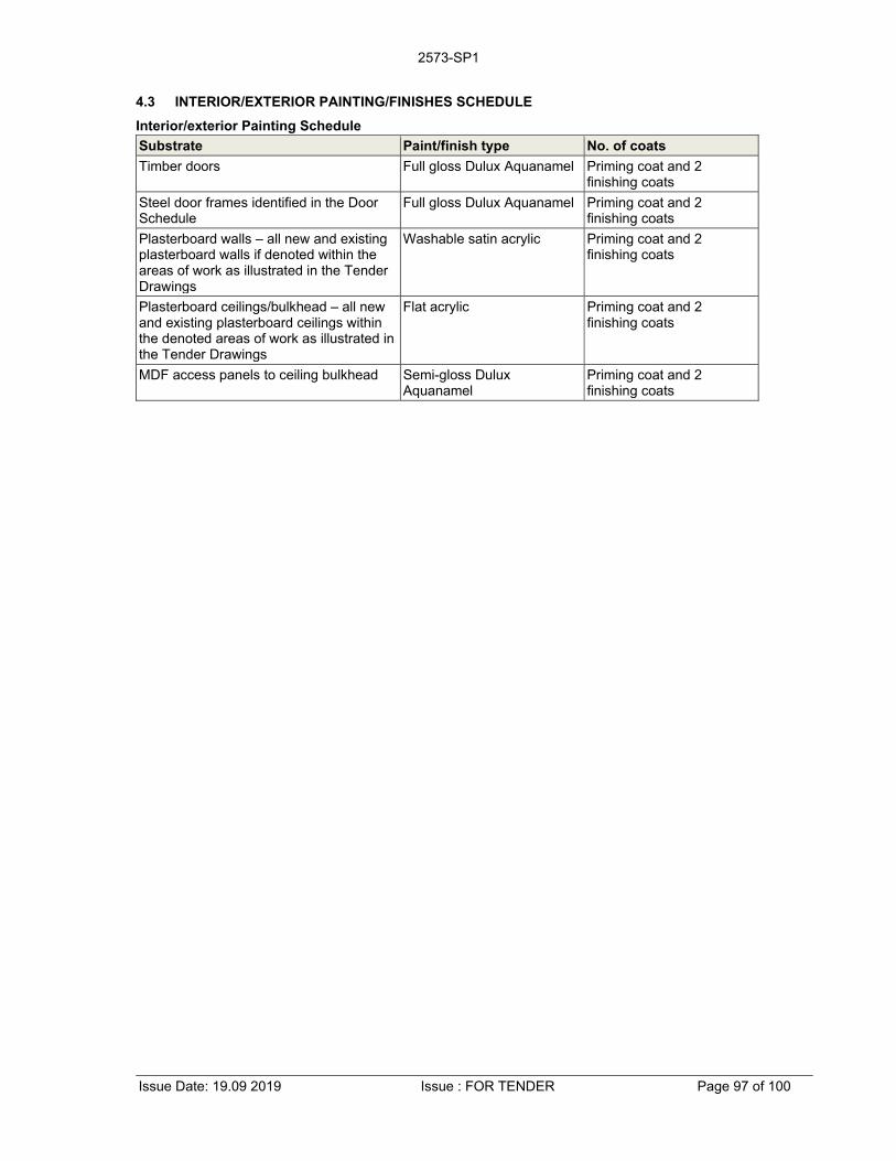
2573-SP1
Issue Date: 19.09 2019 Issue : FOR TENDER Page 97 of 100
4.3 INTERIOR/EXTERIOR PAINTING/FINISHES SCHEDULE
Interior/exterior Painting Schedule
Substrate Paint/finish type No. of coats
Timber doors Full gloss Dulux Aquanamel Priming coat and 2 finishing coats
Steel door frames identified in the Door Schedule
Full gloss Dulux Aquanamel Priming coat and 2 finishing coats
Plasterboard walls – all new and existing plasterboard walls if denoted within the areas of work as illustrated in the Tender Drawings
Washable satin acrylic Priming coat and 2 finishing coats
Plasterboard ceilings/bulkhead – all new and existing plasterboard ceilings within the denoted areas of work as illustrated in the Tender Drawings
Flat acrylic Priming coat and 2 finishing coats
MDF access panels to ceiling bulkhead Semi-gloss Dulux Aquanamel
Priming coat and 2 finishing coats

Specification 2573-SP1
Issue Date: 19.09 2019 Issue : FOR TENDER Page 98 of 100
ATTACHMENT 1 – DOOR SCHEDULE
Door No. Leaf Size-Width in mm
Leaf Size-Height in mm
Leaf Size-Thickness in mm
Leaf Type
Frame Type
Hinge Lock Type
Furniture Barrel Bolt
Closer Seal Door Stop
Finish Grille Keying Floor Bolt
Signage Other/Comments
GN E1 Existing door. Out of scope. No work required.
GN E2 Existing door. Out of scope. No work required.
GN E3 E E E E E E L1 & L2
F x 2 - DC - DS PF - K1 - - Remove existing door furniture & mortice lock and hand to Superintendent’s Representative. Provide cut outs to existing frame to accommodate access control devices. Refer security tender documents.
GN E4 Existing single leaf door. Door leaf and frame to be re-painted. Signage changes as documented. Refer drawings HCA-SCR-PF1, HCA-SCR-PD1
GN E5 Existing double leaf door. Door leaf and frame to be re-painted. Signage changes as documented. Refer drawings HCA-SCR-PF1, HCA-SCR-PD1
GN E6 To suit existing
door frame
To suit existing
door frame
To suit existing
door frame
FR & SCx2
E E L1 F BB DC x 2 SSS - PF - - DB SG Remove existing door leaves and door hardware. Re-use and reinstall existing access control devices. Provide fire rate glazed viewing panels to match door GN/D2 as detailed on the tender drawings. Refer security tender documents. Allow to core through inactive leaf to reticulate cabling to electric strike.
GN E7 Existing single leaf door. Door leaf and frame to be re-painted. Signage changes as documented. Refer drawings HCA-SCR-PF1, HCA-SCR-PD1
GN E8 Existing door. Out of scope. No work required.
GN E9 Existing single leaf door. Door leaf and frame to be re-painted. Signage changes as documented. Refer drawings HCA-SCR-PF1, HCA-SCR-PD1
GN E10 E E E SC E E L1 & L2
F x 2 - DC - - PF RA K1 - - Remove existing door furniture & mortice lock and hand to Superintendent’s Representative. Provide cut outs to existing frame to accommodate access control devices. Refer security tender documents. HB & SS.
GN E11 Existing double leaf door. Door leaf and frame to be re-painted to match door GN/E5. New HVAC, 2 No., RA grilles to be installed as documented. Refer mechanical drawings.
GN E12 Existing door. Out of scope. No work required.
GN E13 Existing double leaf door. Door leaf and frame to be re-painted. Signage changes as documented. Refer drawings HCA-SCR-PF1, HCA-SCR-PD1
GN D1 E 2040x2 E SCx2 ST H L1 & L2
F x 2 BB DC1 x 2 - DS1 x 2 PF1 RA x 2 K1 DB - TH. Provide glazed viewing panels to match existing and as detailed on the tender drawings. Provide cut outs to existing frame to accommodate access control devices. Refer security tender documents. Allow to core through inactive leaf to reticulate cabling to electric strike.
GN D2 950 2040x2 45 FR & SCx2
FRF H L1 & L2
F x 2 BB DC x 2 SSS - PF1 - K1 DB SG TH. Provide fire rate glazed viewing panels to match existing and as detailed on the tender drawings. Provide cut outs to existing frame to accommodate access control devices. Refer security tender documents. Allow to core through inactive leaf to reticulate cabling to electric strike.
GN SD1 1050mm Determine on site with
door operator. Nominally 2350mm
15.5mm GL - - - - - - - - - - - - - Dorma EL301 sliding door operator as specified and detailed. Leaf height to be coordinated with the door operator installer. CR x 2 for activation as detailed. For other electronic security refer security drawings
Note:
1. Internal handles/levers to be free for emergency exit.

Specification 2573-SP1
Issue Date: 19.09 2019 Issue : FOR TENDER Page 99 of 100
Door Schedule Legend
Code Description
E Existing.
ME Match existing
FR Fire rated door leaf/leaves. Fire rating to be -/120/120. Provide rebated meeting stile and/or “T” mullion to double doors. Paint finish as specified. Provide written certification of compliance with required FRL
SC 45 mm thick solid block board flush panel door with a minimum 35 mm block board core (constructed from timber, plywood or cross banded LVL blocks), paint grade finish. Paint finish as specified.
GL 15.5mm thick clear toughened laminated glass with arrised edges all round
FRF Steel fire rated door frame. Fire rating to be -/120/120. Rebates to suit door thickness and required fire rating. Install as recommended by the manufacturer to achieve fire rating. Paint finish as specified.
ST Steel door frame, double rebate - 1.6mm thick, profiled to suit door dimensions and hardware and as detailed on the tender drawings. Cut out to suit specified lock and/or electric strike. Permanently fixed flush with the adjoining partition studs. Paint finish to match existing frames. Paint finish as specified.
H Equal to Lane Sinter-lube 100 x 100 x 3.2 mm fixed pin stainless steel hinge - minimum 4 No. per leaf, 2 No. fixed at top of door.
L1 Lockwood 3579ELAM2, SC mortice lock. Inside: opened by handle at all times. Outside: fixed handle opened by key from outside. Key locks or unlocks outside handle. Use only the strike plates provided with the specified locks or latches not ‘universal’ strike plates. Provide rebate kit as required for double leaf doors, mount at the same height as other mortice locks within the building if and as required.
L2 Lockwood 35791 mortice bolt. Inside: opened by handle at all times. Outside: fixed handle opened by key from outside. Use only the strike plates provided with the specified locks or latches not ‘universal’ strike plates. Provide rebate kit as required for double leaf doors, mount at the same height as other mortice bolts within the building if and as required.
F Lockwood 200 Series Artefact 10mm radius corner plate162x162x3mm stainless steel plate door furniture with 90 stainless steel lever handle. Oval lock cylinder. SS finish. Handing to suit.
BB Lockwood L333 – 150SCDP barrel bolt to top of inactive leaf. Include flat plate ferrule to door head and ferrule to floor.
DC Lockwood FD481 mechanical door closer & selector for double doors with -/120/120 FRL
DC1 Lockwood 7726HDASIL mechanical door closer, surface mounted door closer – one per leaf
DB ADI lockable bolt. ADI 5004. To inactive leaf. Include flat plate ferrule to floor.
S1 Raven RP24 to door frame (all round including stiles and head), Raven RP38 (semi-morticed) to threshold (Raven RP16 to meeting stile of double doors) - Anodised satin clear finish.
DS Lockwood 2308SP floor mounted door stop - one per leaf.
DS1 Equal or similar to Delf PH7458+Door Stop Foot Operated - door leaf mounted foot operated door stop – one per leaf.
RA Return air grille Refer mechanical documents for details
K1 Lock cylinders will be provided by others. Allow to install. Coordinate activities as required on site.
TH Transfer hinge for cabling to electric strike on the inactive leaf by security contractor
HB 2 No. hinge bolts equal to Chubb WS7
SS Strike shield equal to Boyd SS-008 fitted to protect the mortice lock/latch
PF Paint finish door & frame in Dulux Aquanamel. Undercoat followed by two finishing coats. Door leaf colour to match existing adjacent doors. Door frame colour to be DULUX Grey Steel 2, 00NN 53/000.
PF1 Paint finish door & frame in Dulux Aquanamel. Undercoat followed by two finishing coats. Frame colour to be white on public foyer side and DULUX Grey Steel 2, 00NN 53/000 on the other side. Door leaf to be coachwood veneer to public foyer side finished with two coats of clear satin single pack polyurethane. Colour to the other side and edges to be white to match existing. Steel frame around glass viewing panels to be painted to match the coachwood.
SG Install signage as required by clause D2.23 of the National Construction Code which reads “FIRE SAFETY DOOR DO NOT OBSTRUCT DO NOT KEEP OPEN”. The text is to be in capital letters not less than 20 mm high in a colour contrasting with the colour of the door leaf
SSS To double leaf doors install smoke seals equal to Raven RP78Si, RP38Si and RP16Si. Install to manufacturers recommendations
SSS1 To single leaf door install smoke seals equal to Raven RP78Si and RP38Si. Install to manufacturers recommendations

Specification 2573-SP1
Issue Date: 19.09 2019 Issue : FOR TENDER Page 100 of 100
ATTACHMENT 2 – SAMPLE TABLE
Item Description Quantity
Skirtings Plain natural anodised aluminium skirting, black sheet vinyl skirting and 2 channel natural anodised aluminium skirting 300mm sample of each
Partition suite All relevant profiles such as head section, glazing transoms, glazing mullions, door frame stiles and the like as described in the tender drawings 1 of each
Window Frames Single hung aluminium window frame over joinery J03 & glass framing over joinery J01
Door veneer Coachwood veneer to doors GN/D1 & GN/D2
Joinery Specified laminate for joinery tops 300mm sample of each
Specified laminate for joinery carcase and doors 300mm sample of each
Painting Submit, on representative substrates, samples of each paint colour illustrating, colour, gloss level and texture 1 of each
Regupol rubber floor tile Sample of the specified Regupol 600x600x4mm rubber floor tile Vitality Nome 1 tile sample
Glulam bench counter Sample of finished coachwood laminated timber and solid coachwood shark nose edge as detailed 200x200mm sample
Glulam timber Sample of finished coachwood glulam laminated timber or similar 200x200mm sample
Visual indicators Film to glass panels 200x100mm sample
Bollard for card reader Stainless steel as specified 200x200mm sample
Submit samples of the above items for permission to use and incorporate into the works before any placing any orders. Delays and costs arising as a result of late submission of samples shall be borne by the Contractor.
![FEDERAL COURT OF AUSTRALIA - Victoria Branch · - 4 - FEDERAL COURT OF AUSTRALIA United Firefighters’ Union of Australia v Country Fire Authority [2015] FCAFC 1 Citation: …](https://static.fdocuments.in/doc/165x107/5af0b3057f8b9ac62b8efefc/federal-court-of-australia-victoria-4-federal-court-of-australia-united-firefighters.jpg)