PROJECT GASBUGGY WELL PLUGGING AND SITE RESTORATION PLAN
70
NVO 195 PROJECT GASBUGGY WELL PLUGGING AND SITE RESTORATION PLAN NOTICE sponsored by the United Stales Government: Neither the United States nor the United States Department of Energy, nor any of their crnployeea, nor any of thew contractors, subeontracton, or their employees, maker any warranty, express or mplicd, or assumes any legal liability or rerponsibllity for the accuracy, completeness or usefulness of any information, apparatus, product or process daclosed, or represents that its use would not infrmge privately awned nghu. JULY 1978 PREPARED BY THE ENGINEERING AND ENERGY APPLICATIONS DIVISION UNITED STATES DEPARTMENT Off ENERGY NEVADA OPERATIONS OFFICE @STR~UTW QB 31s ~0cu-T UNmTED
Transcript of PROJECT GASBUGGY WELL PLUGGING AND SITE RESTORATION PLAN

NVO 195
PROJECT GASBUGGY WELL PLUGGING
AND SITE RESTORATION PLAN
NOTICE
sponsored by the United Stales Government: Neither the United States nor the United States Department of Energy, nor any of their crnployeea, nor any of thew contractors, subeontracton, or their employees, maker any warranty, express or mplicd, or assumes any legal liability or rerponsibllity for the accuracy, completeness or usefulness of any information, apparatus, product or process daclosed, or represents that its use would not infrmge privately awned nghu.
JULY 1978
PREPARED BY THE ENGINEERING AND ENERGY APPLICATIONS DIVISION
UNITED STATES DEPARTMENT Off ENERGY NEVADA OPERATIONS OFFICE
@ S T R ~ U T W QB 3 1 s ~0cu-T U N m T E D

DISCLAIMER
This report was prepared as an account of work sponsored by an agency of the United States Government. Neither the United States Government nor any agency Thereof, nor any of their employees, makes any warranty, express or implied, or assumes any legal liability or responsibility for the accuracy, completeness, or usefulness of any information, apparatus, product, or process disclosed, or represents that its use would not infringe privately owned rights. Reference herein to any specific commercial product, process, or service by trade name, trademark, manufacturer, or otherwise does not necessarily constitute or imply its endorsement, recommendation, or favoring by the United States Government or any agency thereof. The views and opinions of authors expressed herein do not necessarily state or reflect those of the United States Government or any agency thereof.

DISCLAIMER Portions of this document may be illegible in electronic image products. Images are produced from the best available original document.

ABSTRACT
This document is the operational plan for conducting 'the final restoration work at the site of the first U . S . underground nuclear experiment for the stimulation of low-productivity natural gas reservoirs. The plan includes well plugging procedures, surface facilities decontamination and removal procedures, radiological guidelines, and environmental considerations.

PROJECT GASBUGGY WELL PLUGGING AND SITE RESTORATION PLAN
TABLE OF CONTENTS
Page
I. INTRODUCTION . . . . . . . . . . . . . . . . . . . . . . . . 1
A. Purpose . . . . . . . . . . . . . . . . . . . . . . . . B. Background. . . . . . . . . . . . . . . . . . . . . . . C. Author i ty . . . . . . . . . . . . . . . . . . . . . . .
1 1 3
11. CURRENT SITE STATUS . . . . . . . . . . . . . . . . . . . . . . 4
A. Lands . . . . . . . . . . . . . . . . . . . . . . . . . B. Wells and Appurtenances . . . . . . . . . . . . . . . . C. Sur face F a c i l i t i e s . . . . . . . . . . . . . . . . . . . D. Topography . . . . . . . . . . . . . . . . . . . . . . . E. Radio logica l Conditions . . . . . . . . . . . . . . . .
111. ORGANIZATION AND MANAGEMENT CONCEPT . . . . . . . . . . . . . 9
A. Department of Energy, Nevada Operations Of f i ce (DOE/NV) . . . . . . . . . . . . . . . . . . . . . . . 9
B. Fenix & Scisson (F&S) . . . . . . . . . . . . . . . . . 10 C. Eber l ine Instrument Corporation (Eber l ine) . . . . . . . 10 D. E l Paso Na tu ra l G a s Company (EPNG) . . . . . . . . . . . 11
IV. GENERALIZED SITE ACTIVITIES AND LOGISTICS . . . . . . . . . . 11
A. T r a i l e r s . . . . . . . . . . . . . . . . . . . . . . . . B. E l e c t r i c a l Power . . . . . . . . . . . . . . . . . . . . C. Communications . . . . . . . . . . . . . . . . . . . . . D. Construct ion Water . . . . . . . . . . . . . . . . . . . E. Ve.hic1e.s . . . . . . . . . . . . . . . . . . . . . . . . F. Occupational Heal th and Sa fe ty . . . . . . . . . . . . . G. S i t e Maintenance . . . . . . . . . . . . . . . . . . . . H. Miscellaneous . . . . . . . . . . . . . . . . . . . . .
11 11 11 11 1 2 1 2 13 1 3
V. RADIOLOGICAL SUPPORT PLAN . . . . . . . . . . . . . . . . . . 13
A. Purpose . . . . . . . . . . . . . . . . . . . . . . . . 1 3 13
C. Personnel Sa fe ty . . . . . . . . . . . . . . . . . . . . . 13 D. Radio logica l Procedures f o r Decontamination . . . . . . 1 4 E. Radio logica l Criteria P r o j e c t Gasbuggy . . . . . . . . . 16
2 1
B. Current Radio logica l Conditions . . . . . . . . . . . .
F. F i n a l S i t e Survey . . . . . . . . . . . . . . . . . . .
i
TABLE OF CONTENTS (Continued)
Page
SITE RESTORATION AND WELL PLUGGING PROCEDURES . . . . . . . . 21
A. Surface Facilities Decommissioning . . . . . . . . . . . 21 B. Radiological Waste . . . . . . . . . . . . . . . . . . . 22 C. Packaging and Transportation . . . . . . . . . . . . . . 22 D. Earthwork and Revegetation . . . . . . . . . . . . . . . 23 E. Site Monumentation . . . . . . . . . . . . . . . . . . . 23 F. Final Land Disposition . . . . . . . . . . . . . . . . . 24 G. Well Plugging and Abandonment . . . . . . . . . . . . . 24
1. WellGB-1.. . . . . . . . . . . . . . . . . . . . 24 2. Well GB-2RS . . . . . . . . . . . . . . . . . . . . 27 3. WellGB-3.. . . . . . . . . . . . . . . . . . . . 31 4. Well GB-ER . . . . . . . . . . . . . . . . . . . . 35 5. WellGB-D.. . . . . . . . . . . . . . . . . . . . 40
H. Salvable Wellhead Components . . . . . . . . . . . . . . VII. PUBLIC INFORMATION . . . . . . . . . . . . . . . . . . . . .
VIII.
A. NewsReleases . . . . . . . . . . . . . . . . . . . . . B. Individual Correspondence . . . . . . . . . . . . . . . REPORTS . . . . . . . . . . . . . . . . . . . . . . . . . . . A . Fenix& Scisson . . . . . . . . . . . . . . . . . . . . B. Eberline.. . . . . . . . . . . . . . . . . . . . . . .
IX. SURVEILLANCE PROGRAM . . . . . . . . . . . . . . . . . . . . A. Sampling Network . . . . . . . . . . . . . . . . . . . . B. Analyses.. . . . . . . . . . . . . . . . . . . . . . . C. Reports . . . . . . . . . . . . . . . . . . . . . . . .
X. SCHEDULE . . . . . . . . . . . . . . . . . . . . . . . . . . . APPENDICES
A. Environmental Considerations
B. Radiological Field Operations Plan (to be supplied)
C. Permits and Sundry Notices
44
44
44 44
44
44 45
45
45 47 47
47
D. Government-Owned Materials Inventory
E. Distribution List
ii

PROJECT GASBUGGY WELL PLUGGING AND SITE RESTORATION PLAN
A.
B.
I . INTRODUCTION
Purpose
This p l an has been developed t o e s t a b l i s h t h e o b j e c t i v e s and set f o r t h t h e procedures and gu ide l ines f o r t h e r e s t o r a t i o n of t h e P ro jec t Gasbuggy s i t e , which w a s t h e l o c a t i o n of t h e f i r s t U.S. underground nuclear experi- ment f o r t h e s t imu la t ion of low-productivity n a t u r a l gas r e s e r v o i r s . The gene ra l o b j e c t i v e s of t h e s i t e r e s t o r a t i o n p r o j e c t are t o plug and abandon a l l p ro jec t - r e l a t ed bore holes , remove su r face f a c i l i t i e s , and r e t u r n t h e s i t e t o i t s p r e t e s t s t a t u s , Deta i led ob jec t ives , s p e c i f i c procedures, and gu ide l ines which w i l l be followed during f i e l d a c t i v i t i e s are descr ibed he re in .
Background
I n 1958, t h e E l Paso Natura l G a s Company (EPNG) expressed interest i n t h e s t i m u l a t i o n of gas r e s e r v o i r s wi th nuc lear explos ives , of such a procedure w a s presented i n a f e a s i b i l i t y s tudy which w a s completed i n 1965. The s tudy w a s a j o i n t e f f o r t undertaken by EPNG, t h e U.S. Atomic Energy Commission (AEC) (now p a r t of t h e Department of Energy), and t h e Department of I n t e r i o r ' s Bureau of Mines, with t echn ica l a s s i s t a n c e from t h e Lawrence Radiat ion Laboratory (LRL) (now Lawrence Livermore Laboratory) . The s tudy, t i t l e d P r o j e c t Gasbuggy, descr ibed t h e nuc lear s t i m u l a t i o n of a gas r e s e r v o i r i n t h e P ic tu red C l i f f s sandstone formation i n t h e San Juan Basin of northwestern New llexico approximately 75 m i l e s east of Farmington (Figure 1).
The p r a c t i c a b i l i t y
EPNG subsequent ly proposed t o t h e AEC t h a t P r o j e c t Gasbuggy be conducted as a j o i n t Government-industry venture . The AEC concluded t h a t Gasbuggy would be a va luab le t echn ica l experiment and, toge ther with t h e Department of the I n t e r i o r , signed a c o n t r a c t w i t h EPNG on January 31, 1967.
D r i l l i n g t o assess t h e p o t e n t i a l of t h e s i t e began i n e a r l y 1967. Upon completion of two explora tory w e l l s , GB-1 and GB-2, t h e New Mexico San Juan Basin s i t e w a s accepted and i n June 1967, d r i l l i n g of t h e nuc lear emplacement hole , GB-E, w a s s t a r t e d . 'On December 10, 1967, a 29-kiloton nuc lea r explos ive w a s detonated a t a depth of approximately 4,240 f e e t i n t h e low-permeability P ic tured C l i f f s sandstone formation.
Af te r r e e n t r y d r i l l i n g , s i x major product ion tests were conducted. Two took p l ace i n 1968, t h r e e i n 1969, and t h e l a s t i n 1973. A t o t a l of approximately 400 m i l l i o n cubic f e e t (MMCF) of gas w a s produced and f l a r e d t o t h e atmosphere dur ing t h i s f ive-year t e s t i n g per iod. The r e e n t r y w e l l h a s been shu t i n s i n c e t h e 1973 p roduc t iv i ty test , with only p r e s s u r e monitor ing being conducted and small gas samples p e r i o d i c a l l y taken.
1

Figure 1 Project Gasbuggy Area h p
2

It has been determined t h a t t h e r e is no longer a programmatic need t o maintain t h e P r o j e c t Gasbuggy w e l l complex, and a l l involved p r o j e c t p a r t i c i p a n t s have agreed t h a t t h e f i v e p r o j e c t - r e l a t e d w e l l s should be plugged and abandoned and t h e s i t e r e l eased f o r u n r e s t r i c t e d s u r f a c e use.
C. Authori ty
1. References
a . Contract AT(04-3)-711, dated January 31, 1967, signed by t h e AEC, Department of I n t e r i o r , and t h e EPNG.
b. Memorandum of Understanding, dated March 23, 1967, between t h e Department of Agr i cu l tu re ’ s U.S. Forest Service (USFS) and t h e AEC.
c . EPNG le t te r dated J u l y 23, 1976, D. N. Canfield t o DOE/NV, M. E. Gates.
d. DOE/NV l e t t e r dated August 11, 1976, t o DOE/MA, DOE/OG&ST, LASL, LLL, and SL.
e. Responses from a l l r e c i p i e n t s of Reference 1.d. l e t te r .
2. The b a s i c r e s p o n s i b i l i t y of DOE t o conduct t h e r e s t o r a t i o n i s con- t a i n e d i n t h e referenced c o n t r a c t and Memorandum of Understanding, w i t h a p p l i c a b l e p o r t i o n s shown h e r e as fo l lows:
a. Reference 1.a. above, Ar t ic le I I ( b ) :
P r o j e c t Gasbuggy, as de l inea ted i n t h i s c o n t r a c t , is a coopera- 11
t i ve e f f o r t between t h e Government and t h e Company; each of t h e p a r t i e s i s assuming r e s p o n s i b i l i t y f o r performing c e r t a i n s p e c i f i e d func t ions a t i t s own c o s t and each is, accordingly, prepared t o a s s u m e r e s p o n s i b i l i t y for increases i n t h e c o s t of performing i t s f u n c t i o n s as may develop during t h e execution of t h e p r o j e c t . Each p a r t y s h a l l proceed promptly t o perform i t s p o r t i o n s of t h e work i n accord wi th a j o i n t l y coordinated t i m e schedule t o be issued by t h e Commission. Since t h e explosion of a nuc lea r device i s involved i n t h e execut ion of t h i s p r o j e c t , t h e Commission, because of i t s r e s p o n s i b i l i t i e s i n connection therewith, must have and i s hereby given t h e r i g h t t o c o n t r o l t h e execut ion of t h e p r o j e c t i n a l l phases of ope ra t ions involv- i n g t h e nuc lea r device, i nc lud ing s i t e p repa ra t ion , emplacement, de tona t ion , d i s p o s i t i o n of - r a d i o a c t i v e substances, and pub l i c h e a l t h and s a f e t y . ”
3

b. Reference 1.a. above, Art ic le IV(b) (8 ) ( v i ) :
"Roll-Up
Subsequent t o detonat ion, t h e Company s h a l l remove a l l t ra i lers , t e c h n i c a l s t r u c t u r e s , cons t ruc t ion equipment, t e s t i n g equipment and a s s o c i a t e d material t o a p o i n t mutually agreed upon which is n o t more d i s t a n t than t h e Gobernador Camp. The Company w i l l a l s o c l e a n and remove s u r f a c e d e b r i s from the area of t h e emplace- ment ho le , c o n t r o l p o i n t s and Recording Trailer Park areas; provided, however, t h e Company s h a l l have no o b l i g a t i o n t o remove r a d i o a c t i v e o r contaminated material o r debris ."
c . Reference 1.b. above, paragraph C.9:
"That upon terminat ion of t h i s agreement, t h e p a r t i e s s h a l l mutually ag ree on removal o r o t h e r d i s p o s i t i o n of a l l s t r u c t u r e s and improvements which have been placed on Nat ional Fo res t lands i n t h e e x e r c i s e of t h i s use."
3. The concurrence of a l l p r o j e c t p a r t i c i p a n t s t o proceed wi th s i t e r e s t o r a t i o n is contained i n responses t o Reference 1.d. l e t te r above.
11. CURRENT SITE STATUS
A. Lands
The p r o j e c t i n s t a l l a t i o n s (Figure 2) c o n s i s t i n g of t h e ground zero (GZ) area, t h e r eco rd ing t ra i ler park (RTP), t h e c o n t r o l p o i n t (CP), and t h e h e l i c o p t e r pad w e r e l oca t ed on l ands w i t h i n t h e Carson Nat ional Fo res t . The use of t h e s e l ands f o r t h e Gasbuggy p r o j e c t w a s e s t a b l i s h e d i n t h e p rev ious ly c i t e d Memorandum of Understanding between t h e U.S. Fo res t Se rv ice and t h e U.S. Atomic Energy Commission. Addit ional ly , by land withdrawal a c t i o n of Pub l i c Land Order 4232, dated June 22, 1967, t h e Bureau o f Land Management withdrew from a l l forms of appropr i a t ion , i nc lud ing mining and mineral l e a s i n g l a w s , and reserved f o r t h e use of t h e Atomic Energy Commission t h e s u r f a c e and subsurface of lands w i t h i n Sect ion 36, T29N, R4W, New Mexico P r i n c i p a l Meridian. Surface and subsurface ope ra t ing r i g h t s t o l ands w i t h i n t h e SW 1 / 4 of t h e descr ibed s e c t i o n were reserved f o r t h e use of t h e AEC under s t i p u l a t i o n s of Contract AT(04-3)-711. Access t o t h e p r o j e c t s i te w a s by a road t r a v e r s i n g t h e J i c a r i l l o Apache Indian Reservation. Upgrading and extending t h i s roadway w a s accomplished by t h e New Mexico S t a t e Highway Department through EPNG under s t i p u l a t i o n s i n Contract AT(04-3)-711. This road w a s provided f o r P r o j e c t Gasbuggy use b u t t h e p r o j e c t d i d n o t a c q u i r e c o n t r o l o r r e s p o n s i b i l i t y f o r i t s main- tenance.
B. Wells and Appurtenances
Four w e l l s (GB-1, GB-2, GB-3, and GB-E) were d r i l l e d f o r t h e performance of P r o j e c t Gasbuggy. A f i f t h w e l l , GB-D, no t a p a r t of P r o j e c t Gasbuggy,
4


w a s d r i l l e d and instrumented as a n add-on p r o j e c t f o r t h e Advanced Research P r o j e c t s Agency (ARPA). Well l o c a t i o n s are shown i n Figure 3. General information on t h e w e l l s i s as follows:
1.
2.
3 .
4.
5.
Well No. GB-1: A preshot test w e l l d r i l l e d by EPNG, t o a t o t a l depth of 4,306 f e e t with a 9 5/8-inch production casing set and cemented a t 3,741 f e e t . The lower 1,500 f e e t of tubing i s f i b e r g l a s s with a t t ached instrument packages and t h e upper 2,750 f e e t i s steel. Conductor c a b l e s are a t t ached t o t h e e x t e r i o r of t h e tubing, and i t i s cemented t o 2,812 f e e t and mud-stemmed from 2 ,812 f e e t t o t h e surface.
A 2 3/8-inch tubing s t r i n g is set a t 4,253 f e e t .
Well No. GB-2: A presho t t e s t w e l l d r i l l e d by EPNG t o a t o t a l depth of 4,246 f e e t w i t h 7-inch cas ing set a t 3,906 f e e t . h o l e w a s stemmed t o 3,000 f e e t w i th cement preshot and d r i l l e d ou t by AEC t o 3,812 f e e t (GB-2R) where co l l apsed cas ing w a s encountered during pos t sho t r e e n t r y at tempts . s i d e t r a c k i n g o u t of t h e 7-inch cas ing a t 3,691 f e e t t o a t o t a l depth of 4,600 f e e t (GB-2RS). set a t 4,224 f e e t i n t h e open h o l e s i d e t r a c k . The tubing w a s pe r fo ra t ed from 4,052 f e e t t o 4,063 f e e t , bu t no production was obtained.
The o r i g i n a l
The r e e n t r y w a s continued by
A 2 3/8-inch production tubing s t r i n g w a s
W e l l N o . GB-3: A pos t sho t test w e l l d r i l l e d by EPNG t o a t o t a l depth of 4,809 f e e t and completed with a 4 1/2-inch l i n e r hung i n s i d e a 7-inch c a s i n g a t 3,743 f e e t . Liner s e t t i n g depth is 4,809 f e e t with p e r f o r a t i o n s from 3,922 t o 4,200 f e e t . The l i n e r is n o t cemented. Production i s through 2 3/8-inch tubing set a t 4,190 f e e t .
Well No. GB-E: The nuc lea r device emplacement ho le d r i l l e d by t h e AEC t o a t o t a l depth of 4,350 f e e t with a diameter of 28 inches. The h o l e w a s cased wi th 20-inch-diameter cas ing set a t 4,324 f e e t and cemented t o t h e surface. The device w a s emplaced with 4,227 f e e t of 7-inch-diameter cas ing con ta in ing e i g h t s l o t t e d i n t e r v a l s and cab le s a t t a c h e d t o t h e o u t e r su r f ace . The 7-inch casing and t h e -/-inch by 20-inch annulus were stemmed wi th cement and sand t o t h e su r face . The w e l l w a s r een te red pos t sho t by t h e AEC by d r i l l i n g and destemming t o t h e chimney a t 3,907 f e e t (GB-ER). A 2 7/8-inch production tubing s t r i n g was run t o 3,885 f e e t w i th a packer set a t 3,800 f e e t . o b s t r u c t i o n c u r r e n t l y e x i s t s i n t h i s tubing approximately 8 f e e t below t h e t o p master valve.
An
Well No. GB-D: An AEC-drilled p re sho t ground motion measurement h o l e (ARPA add-on, s e p a r a t e l y funded), l oca t ed o u t s i d e t h e fenced ground ze ro area approximately 1,500 f e e t sou theas t of t h e emplacement hole. T o t a l depth is 4,725 f e e t w i th open ho le below t h e 1 3 3/8-inch cas ing a t 482 f e e t . The w e l l con ta ins fou r instrument packages suspended from a c a b l e a t depths of 4,600 f e e t , 4 ,218 f e e t , 3,600 f e e t , and 3,250 f e e t . The open ho le from t o t a l depth t o 3,106 f e e t i s contin- uously grouted and t h e i n t e r v a l from 3,106 f e e t t o t h e s u r f a c e i s f i l l e d wi th d r i l l i n g mud. The messenger cab le extends t h e f u l l depth of t h e w e l l .
6

>
(3
(3 3
v)
(3
I- o W
7
0
m
a
a
e
7

An a d d i t i o n a l w e l l , EPNG No. 10-36, which e x i s t e d p r i o r t o t h e p r o j e c t execut ion, i s loca ted w i t h i n t h e bounds of t he s i t e abandon- ment work l i m i t s . It i s c u r r e n t l y being used as an a q u i f e r monitoring w e l l and w i l l no t be included i n t h e s i t e abandonment e f f o r t s o t h e r than f o r p o s s i b l e r a d i o l o g i c a l monitoring. t h i s w e l l remains an EPNG r e s p o n s i b i l i t y . Wells GB-1, 2, 3, and E are each equipped with wellheads which w i l l be removed as p a r t of t h e w e l l plug and abandonment procedures and r e tu rned t o t h e appro- p r i a t e owners.
F i n a l d i s p o s i t i o n of
See Appendix D f o r equipment ownership determinat ions.
C. Surface Fac i l i t i e s
A l l f a c i l i t i e s a s s o c i a t e d w i t h t h e former c o n t r o l po in t (CP), recording t ra i le r park (RTP), and h e l i c o p t e r pad l o c a t i o n s have been removed; t h e areas have been graded, shaped, and reseeded; and e x i s t i n g s u r f a c e condi- t i o n s a t t h e s e l o c a t i o n s are considered t o s a t i s f y abandonment cr i ter ia . The areas where work remains t o be performed during t h i s s i t e abandonment inc lude t h e fenced area which encompasses Wells GB-1, 2, 3, E , and 10-36 ( see Figure 3) and any area d i s tu rbed during t h e plugging of Well GB-D. The major f a c i l i t i e s comprising t h e fenced area are as follows:
1. GB-E Production Test ing System: Consis ts of t w o s e p a r a t o r s with i n s u l a t i n g enclosures , manifold systems, skid-mounted metering runs, f low c o n t r o l equipment, 4 1/2-inch-diameter f l a r e l i n e , f l a r e s t a c k , 100-barrel water tank, 6-foot by 4-fOOt pump shed, steam-spray system i n an 8-foot by 10-foot m e t a l shed, p l u s connecting water and gas , l i n e s w i t h a s s o c i a t e d valves.
2. Decontamination Pad and P i t : A 20-foot by 40-foot conc re t e pad s loped t o a n excavated p i t approximately 40 f e e t by 20 f e e t by 4 f e e t deep surrounded by a 3-foot-high berm. The p i t con ta ins t h e d e t e r i o r a t e d remains of an a s p h a l t - p l a s t i c l i n i n g ,
3. - Fence: Approximately 3,500 f e e t of 6-foot-high mixed four-s t rand barbed w i r e and woven w i r e f ence on s teel pos t s w i th one 16-foot-wide double g a t e and two 12-foot-wide s i n g l e ga t e s .
4 . Miscellaneous: Three s e p a r a t o r s , fou r 6-foot by &foot galvanized metal s t o r a g e sheds, f o u r l i g h t s tandards, t h r e e e lec t r ica l panel boards, one p ipe s t anch ion set i n a conc re t e base, two abandoned s e p t i c t anks , t h r e e wellhead l u b r i c a t o r platforms, and miscellaneous conc re t e pads approximately 6 f e e t by 4 f e e t i n s i z e .
D. Topography
The e x i s t i n g l and contours w i t h i n t h e s i t e abandonment s u r f a c e work l i m i t s o r p rev ious ly descr ibed GZ fenced area conform t o t h e surrounding t e r r a i n , which can be descr ibed as r e l a t i v e l y f l a t t o gen t ly r o l l i n g , Mud reserve p i t s used during t h e d r i l l i n g phase have been b a c k f i l l e d and t h e r e are no unna tu ra l appearing land f e a t u r e s except f o r t h e decontamina- t i o n p i t and surrounding berm a t t h e edge of t h e concrete pad. r e v e g e t a t i o n h a s taken p l a c e throughout t h e a f f e c t e d areas. EPNG and DOE
Natural
8
1. . . -. . .. . . .. - -

E.
A.
have graded and seeded a l l o t h e r p r o j e c t i n s t a l l a t i o n areas and no addi- t i o n a l grading o r seeding w i l l be performed except as may be required because of s u r f a c e d i s tu rbance during t h e s i te abandonment work.
Radiological Conditions
See Radiological Support Plan, Sect ion V.
111. ORGANIZATION AND MANAGEMENT CONCEPT
Department of Energy, Nevada Operations Of f i ce (DOE/NV)
1. The DOE, through t h e Manager, NV, w i l l appoint a DOE P r o j e c t Director who w i l l have t h e o v e r a l l r e s p o n s i b i l i t y f o r t h e achievement of a l l p r o j e c t o b j e c t i v e s . are as follows:
H i s major areas of r e s p o n s i b i l i t y and a u t h o r i t y
a.
b.
C .
d.
e.
f .
Provide a p r o j e c t plan.
Provide a gene ra l support c o n t r a c t o r , Fenix & Scisson (F&S), and a r a d i o l o g i c a l support c o n t r a c t o r , Eberl ine Instrument Corporation (Ebe r l ine ) , t o accomplish w e l l plugging and s i t e r e s t o r a t i o n work descr ibed i n Sec t ions I V through V I of t h i s p l a n . Review and c e r t i f y t h e p rov i s ions f o r t h e safeguarding of personnel and property.
Provide r a d i o l o g i c a l c o n t r o l , c r i t e r i a , and i n t e r p r e t a t i o n .
Approve a l l major changes t o t h e p r o j e c t plan.
Manage and coordinate F&S, Ebe r l ine , and DOE on - s i t e ac t iv i t i e s .
2 . The P r o j e c t D i rec to r w i l l be represented on s i t e by i n d i v i d u a l s wi th t h e fol lowing des igna t ions and r e s p o n s i b i l i t i e s :
a . P r o j e c t Engineer: The P r o j e c t Engineer w i l l be r e spons ib l e f o r t h e day-to-day ,general p r o j e c t d i r e c t i o n including ‘coordination of t h e F&S and Eber l ine i n t e r f a c e . The P r o j e c t Engineer w i l l make p r o j e c t execut ion d e c i s i o n s wi th in h i s p re sc r ibed l i m i t s of a u t h o r i t y as r equ i r ed t o exped i t e p r o j e c t accomplishment. H e w i l l keep t h e P r o j e c t D i rec to r ‘adv i sed of t h e d a i l y work s t a t u s and w i l l maintain a n up-to-date p r o j e c t c o s t record.
b. Radiological Operations Supervisor (ROS): The ROS w i l l be r e s p o n s i b l e f o r a s s u r i n g t h a t t h e Radiological Support Plan (Sect ion V) and t h e Radiological F i e l d Operations P lan (Appendix B) are i n accordance w i t h p r o j e c t requirements and c u r r e n t DOE r a d i o l o g i c a l cr i ter ia . cond i t ions and w i l l assist i n t h e i n i t i a l on - s i t e coordinat ion of t h e F&S/Eberline i n t e r f a c e .
H e w i l l be cognizant of r a d i o l o g i c a l
9

The ROS w i l l be on s i t e dur ing t h e s t a r t -up of f i e l d ac t iv i t i e s , during. t h e f i n a l s i t e surveying per iod, and a t o t h e r s e l e c t e d per iods as determined by t h e DOE P ro jec t Di rec tor . w i l l provide r a d i o l o g i c a l guidance wi th in h i s prescr ibed l i m i t s of a u t h o r i t y as requi red t o expedi te p r o j e c t accomplishment.
The ROS
B. Fenix & Scisson (F&S)
1. F&S, as t h e gene ra l support con t r ac to r under con t r ac t t o DOE/NV, w i l l provide t h e materials, s e r v i c e s , and t echn ica l d i r e c t i o n requi red t o accomplish a l l w e l l plugging and s i t e r e s t o r a t i o n o b j e c t i v e s except those a s soc ia t ed wi th r a d i o l o g i c a l support . In t h e exercise of t h e above func t ion , F&S w i l l appoint a P r o j e c t Manager wi th t h e fol lowing major areas of r e s p o n s i b i l i t y :
a.
b.
C .
d.
e .
f .
g *
h.
2. The
Provide d e t a i l e d w e l l plugging and abandonment (P&A) procedures.
Obtain and/or coord ina te a l l requi red permits and approvals f o r w e l l P&A and s i t e r e s t o r a t i o n , as necessary, through t h e USGS, t h e New Mexico O i l Conservation Commission, t h e U . S . Fo res t Serv ice , and EPNG.
Execute subcon t rac t s f o r t h e performance of w e l l P&A, su r face f a c i l i t i e s decommissioning and s i t e r e s t o r a t i o n a c t i v i t i e s , except l a b o r support t o Eber l ine ; and provide on - s i t e superv is ion f o r t h e work.
Coordinate as necessary wi th t h e r a d i o l o g i c a l support con t r ac to r , Eber l ine , t o ensure t imely, s a f e , and cos t - e f f ec t ive opera t ions .
Provide adv ice t o DOE and Eber l ine regard ing procedures f o r t h e most economic method of p r o j e c t accomplishment.
Suspend s i t e a c t i v i t i e s and i n i t i a t e emergency procedures i f any ope ra t ion j eopa rd izes personnel o r property.
Provide d a i l y work progress and weekly c o s t r e p o r t s t o t h e DOE P r o j e c t Engineer and provide a s s i s t a n c e as requi red t o eva lua te t h e c o s t and schedule impact of p l an changes p r i o r t o t h e i r implementation.
Provide a f i n a l r e p o r t summarizing w e l l abandonment and s i t e r e s t o r a t i o n ac t iv i t ies .
Program Manager w i l l s t a f f t h e requi red f i e l d organiza t ion t o c a r r y ou t t h e above r e s p o n s i b i l i t i e s .
C. Eber l ine Instrument Corporat ion (Eber l ine)
Eber l ine , as t h e r a d i o l o g i c a l suppor t con t r ac to r under c o n t r a c t t o DOE/NV, w i l l provide t e c h n i c a l d i r e c t i o n and on-s i te superv is ion t o accomplish a l l r a d i o l o g i c a l decontamination work i n accordance wi th DOE r a d i o l o g i c a l c r i t e r i a . Major r e s p o n s i b i l i t i e s are as follows:
10

D.
A.
B.
C.
D.
1.
2.
3 .
4 .
5.
6 .
7.
E l
Provide a Radiological F i e l d Operations Plan which o u t l i n e s a radio- l o g i c a l monitoring, sampling, and a n a l y s i s procedure and s p e c i f i e s r a d i o l o g i c a l c r i te r ia t o be used.
Provide on - s i t e supe rv i s ion and t e c h n i c a l personnel t o execute t h e Radiological F i e l d Operations Plan.
Obtain and d i r e c t subcon t rac to r s as necessary t o assist i n sampling and decontamination procedures.
Coordinate r a d i o l o g i c a l a c t i v i t i e s as necessary with t h e gene ra l support c o n t r a c t o r e f f o r t s t o achieve s a f e , economic, and t imely ope ra t ions .
Keep t h e ROS and/or t h e P r o j e c t Engineer c o n t i n u a l l y advised of r a d i o l o g i c a l cond i t ions and provide a d a i l y work progress r e p o r t .
Maintain a weekly c o s t s t a t u s r e p o r t and assist t h e P r o j e c t Engineer i n p r o j e c t i n g and e s t ima t ing t h e impact of approved program changes.
Provide a Radiat ion Contamination Clearance r e p o r t upon completion of f i e l d operat ions.
Paso Natural Gas Company (EPNG)
EPNG w i l l assist i n ob ta in ing w e l l plugging and abandonment permits and provide c e r t a i n support items as s p e c i f i e d i n Sect ion I V .
I V . GENERALIZED SITE ACTIVITIES AND LOGISTICS
Trailers
F&S w i l l provide one o f f i c e t ra i ler ( l o c a l l y r en ted ) w i th desks and c h a i r s f o r a d m i n i s t r a t i v e use by DOE, F&S, and Eber l ine personnel.
An a d d i t i o n a l t r a i l e r w i l l a l s o be provided through F&S f o r r a d i o l o g i c a l support u se by Eberl ine.
Electr ical Power
EPNG w i l l f u r n i s h a 40-kilowatt generator t o provide ope ra t ing power f o r t h e r a d i o l o g i c a l support t ra i ler and t h e o f f i c e t ra i ler .
Communications
F&S w i l l a r r ange f o r a mobile telephone service. c o n s i s t of s e p a r a t e u n i t s w i t h d i f f e r e n t numbers i n s t a l l e d i n each of t h e two trailers.
The s e r v i c e s h a l l
Construct ion Water
Water w i l l be hauled approximately 8 m i l e s by t r u c k from a w a t e r ho le nea r t h e i n t e r s e c t i o n of Highway 1 7 and t h e s i t e access road.
11
E. Vehicles
Project organizations will be responsible for providing and maintaining their own vehicles.
F. Occupational Health and Safety
1. General
All operations and activities will be conducted in accordance with the standards of the Occupational Safety and Health Act of 1970 (OSHA) . All participating organizations are responsible for the health and safety of their own personnel and for conducting all activities in accordance with procedures that assure:
a. A safe and healthful environment for the employees.
b. Control and minimization of hazards to the public and to personnel or other participants.
c. Minimization of the accidental damage or loss of equipment, materials, and property.
d. Compliance with on-site radiological safety procedures.
2 . Medical Services
a. F&S will make arrangements with the San Juan Hospital in Farming- ton for any hospitalization that may be required.
b. F&S will provide two physician-approved first-aid kits to be located in the officer trailer.
3 . Fire Protection
Three hand-held fire extinguishers will be placed throughout the working area at convenient locations. Extinguishers will be the universal type for control of Class A, B, or C fires.
4 . Radiological Protection
Eberline will provide personnel radiological safety services as described in the Radiological Support Plan, Section V.
5. Potable Water
F&S will provide potable water containers which will be maintained by each participating organization.
12

---
6 . Sanitation
F&S will provide two chemical toilets which will be serviced on a weekly schedule.
G . Site Maintenance
F&S will provide generalized site maintenance such as trash removal, fuel for the EPNG-supplied electrical generator, and general policing of the work areas.
H. Miscellaneous
Reproduction Facility--F&S will provide a desk-top copying machine.
V. RADIOLOGICAL SUPPORT PLAN
A. Purpose
The purpose of this Radiological Support Plan is to establish guidelines, methods, and standards to ensure that all well plugging and site restora- tion activities to be described in Section VI are conducted in a manner that: (1) minimizes radiation exposure to participating personnel and the public, (2) eliminates radiological contamination in excess of DOE criteria at the Gasbuggy site, and (3 ) is technically and economically feasible.
B. Current Radiological Conditions
The extent and levels of surface contamination at the Gasbuggy site have been documented by soil and water sampling programs and site surveys by the Environmental Protection Agency (EPA), EPNG, and DOE, Analyses from these surveys have indicated that there is no radiological contamination of soil or surface waters exceeding DOE site disposal criteria set forth i n Tables 1 and 2 , Sect ion V . E .
Radiological contamination in excess of DOE criteria is expected on interior surfaces of the gas production-testing system from the GB-ER well bore tubing through the flare stack. In addition, a small quantity (approximately 5 to 10 barrels) of tritium-contaminated liquid is contained in the 100-barrel water storage tank.
C. Personnel Safety
1. Bioassays
All operating personnel, i.e.,l those handling or controlling the handling of contaminated material, will submit a urine sample to Eberline upon arrival at the worktsite and again upon permanent departure from the site. operational conditions. required. Eberline will assay the samples for tritium and conduct
Other samples may be required depending on Bioassays of other personnel may also be
13

any o t h e r ana lyses deemed appropr i a t e by t h e ROS. of t h e p r o j e c t , a r e p o r t of t hese ana lyses w i l l be submitted by Eber l ine t o t h e NV Radiological Branch f o r i n c l u s i o n i n t h e REECo master dosimetry f i l e .
Af t e r completion
2. Dosimetry
Operating personnel w i l l be r equ i r ed t o wear personnel dosimeters. The issuance and maintenance of t h e dosimeters w i l l be c o n s i s t e n t w i t h Ebe r l ine ' s approved dosimetry program. A t t h e conclusion of t h e p r o j e c t , personnel dosimetry r e s u l t s w i l l be forwarded t o t h e NV Radiological Branch f o r i n c l u s i o n i n t h e REECo master dosimetry f i l e .
D. Radiological Procedures f o r Decontamination
An o v e r a l l d e s c r i p t i o n of t h e decontamination procedures and system i s given i n Sec t ion V1.A. The a s s o c i a t e d r a d i o l o g i c a l c o n t r o l , monitoring release, and sampling procedures are as follows:
1. Con t ro l
The decontamination area, c o n s i s t i n g of a l a r g e d r i p pan and concrete pad descr ibed i n Sec t ion V I . A . , w i l l be roped o f f and marked wi th a p p r o p r i a t e s i g n s . Another a p p r o p r i a t e l y marked and roped o f f area w i l l be e s t a b l i s h e d f o r holding contaminated materials. be designated as t h e contaminated holding area. Two a d d i t i o n a l areas w i l l be e s t a b l i s h e d f o r r a d i o l o g i c a l l y c l ean EPNG- and Government- owned assets, r e s p e c t i v e l y . These l a t te r areas w i l l n o t r e q u i r e s p e c i a l c o n t r o l measures.
This w i l l
Items of material and equipment w i l l i n i t i a l l y be r a d i o l o g i c a l l y surveyed i n p l ace ; i f they meet t h e release criteria, they w i l l be a p p r o p r i a t e l y marked and placed i n one of t h e c l ean holding areas. I f they do n o t m e e t t h e release cri teria, they w i l l be moved t o t h e decontamination area, and a f t e r a reasonable decontamination e f f o r t , ano the r survey w i l l be conducted. Pending t h e r e s u l t s of t h i s second survey, t h e i t e m ( s ) of material and/or equipment w i l l be moved t o t h e appropr i a t e c l ean o r contaminated holding area f o r e i t h e r release f o r u n r e s t r i c t e d use o r f o r d i s p o s a l as contaminated waste.
2 . Equipment Monitoring and Sampling
I t e m s of equipment having i n a c c e s s i b l e i n t e r i o r s w i l l i n i t i a l l y be f lu shed through wi th steam o r appropr i a t e c l ean ing s o l u t i o n s . When t h e e x i t i n g f l u s h materials are below release l i m i t s f o r tritium, t h e i t e m w i l l be set a s i d e f o r a 24-hour wa i t ing per iod. As a f i n a l check f o r t r i t i u m following t h e 24-hour wai t ing pe r iod , an appropr i a t e amount of d i s t i l l e d "clean" water (commensurate with t h e s i z e of t h e i n t e r n a l area being checked, b u t no t t o exceed one l i t e r ) w i l l be placed i n con tac t w i th a p o r t i o n of t h e s u r f a c e being t e s t e d , e.g. ,
1 4

pouring a liter of water through a pipe or allowing one liter of water to puddle on the inner surface of a tank for a minimum of 30 seconds. analyzed for tritium. If the concentration of tritium in this sample exceeds 5,000 dpm/ml, the decontamination process should be repeated, with DOE'S concurrence, until it is determined the item cannot be decontaminated to an acceptable level for unrestricted use at a reasonable cost. In addition, representative wet swipes of the accessible inner and outer portions of the item being tested will be taken.
Most of this water should be collected and a one cc aliquot
3 . Release of Equipment
A release log will be kept to record the release of all material from the site. Also, appropriate photographic documentation shall be maintained throughout the cleanup. Criteria for release to unrestricted use will be that stated in Tables 1 and 2, Section V . E . , which includes a reference to the American National Standards Insti- tute proposed standard ANSI N328-1976, "Control of Radioactive Surface Contamination on Materials, Equipment and Facilities to Be Released for Uncontrolled Use," and the special criteria for internal inaccessible surfaces described above.
4 . Sampling and Analysis Program
a.
b.
General
Soil, water, urine, swipe, and possibly gas samples will be collected and analyzed for tritium on site. In addition, selected samples will be analyzed for 137Cs and 90Sr at the Radiological Contractor's home laboratory.
Soil Sampling Program
At the conclusion of the 1973 production test, EPNG conducted an extensive soil sampling and analysis program. Soil samples were collected on a 50-foot grid pattern at a 2-foot depth and analyzed for tritium. expected to be more highly contaminated. Results indicated that no samples exceeded approved cleanup criteria.
A finer grid pattern was used in areas
During this final cleanup operation, a complementary 50-foot grid pattern will be sampled near the surface. More extensive sampling will be used in areas expected to be of higher contami- nation. Additional samples will be collected as prescribed by the ROS at both the surface and at depth. All soil samples will be analyzed for tritium on site and selected samples will be analyzed for 137Cs and 90Sr. samples to be analyzed for tritium is foreseen. will be conducted to delineate the extent of the contamination.
A total of 250 or more soil All sampling
15

C .
d.
e.
f.
Water Sampling Program
Deep w e l l water samples are c u r r e n t l y being c o l l e c t e d by t h e EPA. Reference i s made t o SectionlX f o r a d e s c r i p t i o n of t h i s ongoing Long-Term Hydrological Program. ope ra t ion , o p e r a t i o n a l water samples w i l l a l s o be c o l l e c t e d as r equ i r ed and analyzed f o r t r i t i u m .
During t h e cleanup
Gas Sampling Program
It i s no t a n t i c i p a t e d t h a t gas samples w i l l need t o be analyzed. P rov i s ions t o c o l l e c t and analyze t h e s e samples , should t h e need arise, w i l l b e made.
Vegetation Samples
A few v e g e t a t i o n samples from t h e Gasbuggy v i c i n i t y w i l l be c o l l e c t e d and analyzed f o r t r i t i u m f o r pathway documentation purposes. l abo ra to ry .
These ana lyses w i l l be performed a t an o f f - s i t e
Radionucl ide Analysis Sens i t i v i t i e s
Water samples and moisture i n s o i l s a m p l e s w i l l be analyzed f o r t r i t i u m wi th a d e t e c t i o n s e n s i t i v i t y of 2 pCi/ml. s o i l samples w i l l be analyzed f o r 137Cs with a d e t e c t i o n sensi- t i v i t y of 1 pCi/g (wet).,
Selected
E. Radiological Criteria P r o j e c t Gasbuggy
The fol lowing guidel ines* apply t o P r o j e c t Gasbuggy. It is recommended t h a t design and o p e r a t i o n a l a c t i v i t i e s be conducted wi th in t h e s e gu ide l ines i n such a manner as t o reduce t h e release of r a d i o a c t i v e e f f l u e n t s and r a d i a t i o n exposures t o personnel, on and o f f s i te , t o t h e lowest p r a c t i - c a b l e levels. Fur the r , w i t h r e s p e c t t o planned ope ra t ions and any associ- a t e d c o n t r o l l e d releases, exposures t o members of t h e pub l i c should no t exceed 10 pe rcen t of t h e l i m i t s s p e c i f i e d i n DOE Appendix 0524. For s i t u a t i o n s involving inadve r t en t o r a c c i d e n t a l releases, t h e o v e r a l l des ign of t h e experimental program should be c a r e f u l l y reviewed t o ensure t h a t during t h e l i f e t i m e of t h e p r o j e c t , t h e r e w i l l be no s i g n i f i c a n t uncon t ro l l ed release of r a d i o a c t i v i t y o f f t h e c o n t r o l l e d area.
1. General Radiological Criteria
The fol lowing r a d i o l o g i c a l s a f e t y c r i te r ia s h a l l apply during t h e e n t i r e ope ra t ion pe r iod of t h e s e p r o j e c t s :
*These guides were e x t r a c t e d from le t te r , Kel ly t o Miller, A p r i l 1 7 , 1972, "Radiological Sa fe ty Guidance f o r Experiments Involving Nuclear St imulat ion of Natural Gas Wells," and le t te r , Biles t o Johnson, Apr i l 5, 1973, same t i t l e , and from American Nat ional Standards I n s t i t u t e , ANSI N328-1976.
16

2 .
a .
b.
C .
d .
For i n d i v i d u a l s w i th in t h e c o n t r o l l e d area, t h e r a d i a t i o n p r o t e c t i o n s tandards set f o r t h i n DOE Appendix 0524, paragraphs I - A and I V , s h a l l apply.
For i n d i v i d u a l s and populat ion groups i n uncontrol led areas, 10 pe rcen t of t h e r a d i a t i o n p r o t e c t i o n s tandards set f o r t h i n DOE Appendix 0 5 2 4 , paragraph 11-A, s h a l l apply. It is noted t h a t t h e p o t e n t i a l f o r r a d i a t i o n exposure t o i n d i v i d u a l s i n t h e uncon t ro l l ed area from planned ope ra t ions e x i s t e d only during t h e t i m e of production t e s t i n g ( f l a r i n g ) ac t iv i t ies . There are no production t e s t i n g a c t i v i t i e s involved i n t h i s r e s t o r a t i o n p r o j e c t .
I n t h e u n l i k e l y event t h a t an inadve r t en t release of r ad ioac t iv - i t y t o t h e uncontrol led area occurs , every e f f o r t s h a l l be made t o reduce p o t e n t i a l r a d i a t i o n exposure t o i n d i v i d u a l s o f f s i t e t o t h e lowest p r a c t i c a b l e level. Exposure c o n t r o l gu ide l ine s h a l l be consonant with the p r i n c i p l e s and levels of p r o t e c t i v e a c t i o n guidance provided i n Federal Radiat ion Council Reports 5 and 7 .
A l l pe r sona l property, i . e . , bu i ld ings , equipment, and materials, t o be removed from the s i t e f o r uncontrol led use s h a l l m e e t t h e c r i te r ia s p e c i f i e d i n Table 1 o r Table 2 and t h e s p e c i a l cri teria f o r i n t e r n a l i n a c c e s s i b l e s u r f a c e s previously set f o r t h i n Sec t ion D.2. A l l personal property, t r a n s f e r r e d from t h i s s i t e t o another l o c a t i o n where r a d i o l o g i c a l c o n t r o l s are i n e f f e c t , s h a l l have t h e e x t e r n a l su r f aces of such property meet t h e c r i te r ia s p e c i f i e d i n Table 1 o r Table 2 and be packaged f o r t r a n s p o r t i n compliance with DOE Appendix 0529 and U.S. Depart- ment of Transportat ion Regulations.
S i t e Disposal
Decontamination and cleanup, prior t o release of c o n t r o l and respon- s i b i l i t y f o r t h e s i t e by t h e DOE, s h a l l be e f f e c t e d a f t e r considera- t i o n of t h e fol lowing f a c t o r s : (1) e x t e r n a l r a d i a t i o n levels ; (2) migrat ion of r ad ionuc l ides t o man through resuspension i n a i r , movement i n w a t e r , o r passage through food chains; (3) u n r e s t r i c t e d p rope r ty use, immediate and p o t e n t i a l ; ( 4 ) decay and o t h e r removal processes tending t o reduce p o t e n t i a l exposure t o man; and ( 5 ) t h e f e a s i b i l i t y , c o s t , and re la t ive e f f e c t i v e n e s s of f u r t h e r decontamina- t i o n ac t iv i t ies . The cleanup s h a l l be continued u n t i l p o t e n t i a l f u t u r e exposures t o man are not l i k e l y t o exceed a few percent of t h e l i m i t s s p e c i f i e d i n DOE Appendix 0524, paragraph 11-A.
Numerical guidance provided h e r e i n should not be exceeded without c a r e f u l cons ide ra t ion of t h e reasons f o r doing so. than those provided he re may be approved by DOE Headquarters, on a case-by-case b a s i s .
D i f f e r e n t va lues
1 7

c
TABLE 1 SURFACE COtlTAtl INAT ION L Ill I T S U
The l e v e l s may be averaged* over the 1 m2 provided the maximum a c t
of 100 CG i s less than three times the l i m i t value.
t i t y i n any area
L i m i t (Ac t i i t y ) dDm/100 C s
Nucl i de - Total Removable
Group 1: Nuclides f o r which the nonoccupational W C * * 3 a
C i / m o r less o r f o r which the nonoccu- i s 2 x
pat ional lIPcw*+* i s 2 x 10⁻⁷ Ci/m3 o r less; includes AC-227;
Am-241, -242~1, -243; Cf-249, -250, -251, -252; Cm-243, 100
-244, -245, -246, -247, -248; 1-125, -129; rlp-237; Pa-231;
Pb-210; Pu-238, -239, -240, -242, -244; Ra-226, -228;
Th-228, -230.****
Croup 2:
nonoccupational tAPC ** i s 1 x 10-12 ~ i / m 3 o r less o r
f o r which the nonoccupational f!PCv:** i s 1 x Ci/m3 1,000
Those nucl ides n o t i n Group 1 f o r which the
a
o r less; includes Es-254; Fm-256; I-lZC, -131, -133;
Po-210; Ra-223; Sr-90; Th-232; IJ-232. ****
Group 3:
VTaken from ANSI 111328-1976.
Those nucl ides n o t i n Group 1 o r Group 2.
20
200
5,000 1,000
* See tlote f o l l o w i n g Table 2 on app l i ca t i on o f l i m i t s .
*+ MPC,: Maximum Permissible Concentration i n A i r appl icable t o continuous exposure o f members o f the pub l i c as publ ished by o r derived from an a u t h o r i t a t i v e source such as NCRP, I C R P o r NRC (10 CFR, Pa r t 20, Appendix B, Table 2, Column 1).
**+ MPC : Maximum Permissible Concentration i n Water appl icable t o members o f the pubyi c.
*** Values presented hcre are obtained from 10 CFR Par t 20. The most l i m i t i n g o f a l l given MPC values (c.g. soluble vs inso lub le) are t o be used. I n the event of the occurrence o f mixtures of radionucl ides, thc f r ac t i on contr ibuted by each const i tuent o f i t s own l i m i t s h a l l be determined and the sum o f the f rac t i ons must be less than 1.
18

c
TABLE 2 ALTERNATE SURFACE CONTAMINATION L IMITSU
( A l l alpha emitters, except U-nat and Th-nat are considered as a group.)
The leve ls may be averaged over 1 m2* provided the maximum a c t i v i t y i n any area o f
100 cm2 i s less than three times the l i m i t value.
Hucl i d e
L i m i t (Ac t i i t y )
Total . Removable
dpm/100 c f - -
If the contaminant cannot be i d e n t i f i e d ; o r i f aloha
emi t ters o the r than U-nat and Th-nat are present; o r
i f the beta emi t ters comprise Ac-227, Ra-226, Ra-228, . 100 20
1-125 and 1-129.
I f i t i s known t h a t a l l alpha emi t ters are generated
from U-nat and Th-nat; and beta emi t ters are present
which, wh i l e no t i den t i f i ed , do n o t include Ac-227, 1,000 200
10125, 1-129, Ra-226 and Ra-228.
I f i t i s known t h a t alpha emi t ters are generated only
from IJ-nat and Th-nat; and the beta emitters, whi le
n o t i d e n t i f i e d , do n o t inc lude Ac-227, 1-125, 1-129, 5,000 1,000
Sr-90, Ra-223, Ra-228, 1-126, 1-131 and 1-133.
UTaken from ANSI N328-1976 . SABLES 1 AND 2 TO ISOLATED SPOTS o f ACTIVITY:
For purposes o f averaging, any m2 o f sur ace s h a l l be consddered t o be contaminated above the l i m i t , L, appl icable t o 100 cmd if: a. From measurements of a representat ive number, n, o f sections, i t i s determined
t h a t l / n $; S i > - L, where S i i s the dpm/100 CII? determined from measurement of sect ion i; o r
b e on surfaces less than 1 m2, i t i s determined t h a t l / n area o f the surface i n u n i t s o f m2; o r
c. It i s determined t h a t the a c t i v i t y o f a l l i so la ted spots or p a r t i c l e s i n any area less than 100 cm2 exceeds 3L.
S i 2 AL, where A i s the
19

For purposes of planning f o r d i sposa l of a s i t e f o r uncontrol led use , t h e fol lowing r a d i o l o g i c a l s a f e t y guidance is provided:
a .
b.
C.
Surf ace Waters
Contaminated s u r f a c e waters i n excess of 0.1 times t h e concentra- t i o n va lues l i s t e d i n DOE Appendix 0524, Annex A, Table 2, Column 2, s h a l l be disposed of by methods approved by DOE Headquarters. For t r i t i u m , t h i s is 300 pCi/ml.
Bui ldings, Equipment, and Materials
A l l personal property remaining a t t h e s i t e s h a l l be decontami- na t ed as n e a r as p r a c t i c a b l e t o t h e cri teria s p e c i f i e d i n ANSI Standard N328-1976 s p e c i f i c a l l y Table 1 o r 2. For t r i t i u m on ly , t h i s i s 5,000 pCi/lOO cm2 t o t a l or 1,000 pCi/lOO cm2 t o t a l i f 90Sr is p resen t and 1,000 pCi/lOO cm2 removable.
S o i l
Residual contaminated s o i l t o a depth of about fou r f e e t s h a l l be decontaminated o r treated t o the e x t e n t p r a c t i c a b l e as fol lows :
(1) S o i l con ta in ing r e s i d u a l tritium concentrat ions exceeding 3 x p C i / m l of s o i l moisture s h a l l be excavated f o r d i s p o s i t i o n a t an approved b u r i a l ground. Other means of d i s p o s a l must be approved by DOE Headquarters. Based upon p a s t experience, l i t t l e o r no s o i l s h a l l be removed during t h i s r e s t o r a t i o n .
(2) S o i l con ta in ing r e s i d u a l By r a d i a t i o n levels exceeding 0.2 mrad/hr above background ( inc lud ing worldwide f a l l o u t ) measured a t 1 cm s h a l l be excavated f o r d i s p o s i t i o n by means approved by DOE Headquarters. After s u r f a c e r e s t o r a - t i o n , t h e f i n a l average r a d i a t i o n levels s h a l l no t exceed 0.05 mrad/hr By above background ( including worldwide f a l l o u t ) measured a t 1 cm. A l l measurements s h a l l be done w i t h a probe having n o t more than 7 mg p e r cm2 of absorbing material.
(3) S o i l g r a d i e n t s s h a l l be examined by s u i t a b l e sampling and r e s i d u a l contamination s h a l l be removed and disposed of by methods ap roved by DOE Headquarters when these levels
above background ( inc lud ing worldwide f a l l o u t ) . It is no t a n t i c i p a t e d t h a t t e s t - r e l a t e d r a d i o a c t i v i t y with a n CY, decay mode w i l l be encountered. I f such should be t h e case, c r i te r ia w i l l be provided by DOE Headquarters. Based upon experience a t t h e Gasbuggy s i t e , i t i s expected t h a t t r i t i u m w i l l be t h e only r ad ionuc l ide of concern during t h i s r e s t o r a t i o n .
exceed 10 4 pCi/g f o r By decay modes (except t r i t i u m )
20
. . . ..- ~~ . .

d. A f i n a l s i t e surve.y s h a l l be pe.rformed p r i o r t o release of t h e s i t e and cop ie s of a r e p o r t of t h e cleanup e f f o r t and survey r e s u l t s shall be t ransmit ted t o DOE Headquarters. The r e p o r t on t h e s i t e cleanup ope ra t ion s h a l l include a d e s c r i p t i o n of t h e phys ica l and l e g a l measures taken t o prevent deep d r i l l i n g , mining, o r o t h e r r e s t r i c t i o n s on use of t h e site.. Agre.e.me.nts o r arrangements f o r subsequent monitoring should a l s o be described. The c e r t i f i c a t i o n require.me.nt , assoc ia t ed wi th t h i s r e p o r t , is de f ined i n DOE Appendix 5301, dated January 10, 1973, f o r a l l real property and r e l a t e d personal property p r i o r t o any d i s p o s a l o r excessing ac t ion .
e. E f f e c t i v e s i t e cleanup w i l l e l imina te t h e need f o r pe.riodic terrestrial and bioenvironmental surveys and only annual hydrol- ogy sampling w i l l be require.d (se.e Se.ction X) .
F. F i n a l S i te . Survey
The e n t i r e s i t e s u r f a c e w i l l b e surveyed on a 50-foot g r i d . known o r p o s s i b l e contamination w i l l be surveyed on a 10-foot g r i d . These surveys w i l l be made a t 1 cm d i s t a n c e with an HP-210 probe. having less than 7 mg/cm2 of absorbent material. n e a r t h e end of t h e s i te r e s t o r a t i o n ac t iv i t ies .
Areas of
This survey w i l l b e conducted
V I . SITE RESTORATION AND WELL PLUGGING PROCEDURES
A. Surface F a c i l i t i e s Decommissioning
I t is t h e o b j e c t i v e of DOE t o r a d i o l o g i c a l l y decontaminate a l l EPNG materials and equipment t o permit t h e i r release f o r u n r e s t r i c t e d pub l i c use. The e x t e n t of t h e decontamination e f f o r t t h a t may b e required and t h e p r o b a b i l i t y of success can only be determined as t h e work progresses .
The DOE w i l l make a reasonable e f f o r t t o acceptably decontaminate a l l equipment t o conserve equipment and resources f o r f u t u r e EPNG reuse. DOE, however, reserves t h e r i g h t t o determine what c o n s t i t u t e s a reasonable e f f o r t . Those i t e m s which DOE determines cannot be decontaminated with a r easonab le e f f o r t and t h e r e f o r e a t a reasonable c o s t w i l l b e i m e d i a t e . l y t r a n s f e r r e d a t no c o s t t o t h e ownership of DOE. DOE w i l l be r e spons ib l e f o r t h e i r subsequent d i s p o s a l a t an approved f a c i l i t y .
A d e t a i l e d sequence f o r the. s u r f a c e f a c i l i t i e s decommissioning work cannot be f i r m l y e s t a b l i s h e d , but a d e s c r i p t i o n of t h e r equ i r ed primary a c t i v i t i e s i s as follows:
1. Decontamination System: The f i r s t phase of t h e s u r f a c e f a c i l i t y d i s p o s a l w i l l involve t h e cons t ruc t ion of a decontamination system c o n s i s t i n g of a l a r g e steel pan with8-inch-high s i d e s and a 500-gallon sump a t one end. decontamination pad. A p o r t a b l e steam c lean ing u n i t w i l l be set up ad jacen t t o t h e pan. A handling, sampling, swiping, logging, and c l ea rance procedure, as descr ibed i n Sect ion V, w i l l be implemented t o ensure t h a t EPNGowned equipment i s n o t r e l eased f o r u n r e s t r i c t e d pub l i c u se un le s s it meets t h e r a d i o l o g i c a l s a f e t y guide.1ine.s.
The pan w i l l be set on t h e e x i s t i n g concrete
2 1

2.
3.
4 .
5.
Production Tes t ing System: The m j o r components such as t h e two GB-E s e p a r a t o r s w i l l be moved t o t h e decon pan, p a r t i a l l y disassembled and decontaminated by steam c lean ing methods. i nc lude removal of s e p a r a t o r tank ends with a c u t t i n g torch. subsequent rewelding of t h e tanks w i l l be t h e r e s p o n s i b i l i t y of EPNG. The steam condensate generated during t h e steam c lean ing w i l l be r e t a i n e d i n t h e sump and a d d i t i o n a l con ta ine r s as required. The f l a r e s t a c k and o t h e r t u b u l a r i t e m s such as metering runs and flow c o n t r o l manifolds w i l l be c u t i n t o s e c t i o n s and steam cleaned i n t h e decon pan. The f l a r e s t a c k steamer w i l l be removed from t h e m e t a l bu i ld ing and shipped t o t h e Nevada Test S i t e as is . The 100-barrel water s t o r a g e tank w i l l be drained of a l l l i q u i d s ; t h e in spec t ion p l a t e w i l l be removed and t h e s ludge shoveled out and s o l i d i f i e d f o r f i n a l d i s p o s a l by DOE a t an approved r a d i o a c t i v e waste b u r i a l f a c i l i t y . F i n a l d i s p o s a l of t h e condensate and o t h e r accumulated l i q u i d s w i l l be accomplished by vapor i za t ion o r i n j e c t i o n i n t o t h e nuc lea r c a v i t y (see Sect ion B ) .
The disassembly may The
Concrete Decontamination Pad and P i t : conc re t e pad broken up and placed i n t h e p i t along with t h e l i n i n g
The p i t w i l l be deepened, t h e
and bu r i ed during b a c k f i l l i n g .
Fence: The p rev ious ly descr ibed fence, including p o s t s and g a t e s , w i l l be taken down f o r removal from t h e s i t e by EPNG.
Miscellaneous Items: Cer t a in i t e m s such as t h e t h r e e a d d i t i o n a l s e p a r a t o r s , metal s t o r a g e sheds, l i g h t s tandards, wellhead l u b r i c a t o r platforms, e tc . , w i l l be removed from t h e s i t e as is by EPNG. The underground s e p t i c t anks w i l l be f i l l e d with sand and abandoned i n p l ace . The e x i s t i n g p i p e frame w i l l remain i n p l ace and ownership t r a n s f e r r e d t o t h e U.S. Fores t Service f o r t h e i r u se i n s i t e monumen- t a t ion.
B. Radiological Waste
Radiological waste accumulated during t h e r e s t o r a t i o n process w i l l include contaminated l i q u i d s and sludge from equipment i n t e r i o r s , and s o i l , The l i q u i d s w i l l be disposed of by i n j e c t i o n i n t o t h e nuc lea r chimney r eg ion through t h e GB-ER w e l l bore. through f i n a l steam c lean ing e f f o r t s a f t e r t h e GB-ER w e l l bore is sea l ed w i l l be disposed of by vaporizat ion.* diatomaceous e a r t h and cement and s e a l e d i n DOT-approved con ta ine r s f o r subsequent shipment as descr ibed below.
Those contaminated l i q u i d s which are generated
Sludge and s o i l w i l l be mixed with
C. Packaging and Transpor t a t ion
A l l materials, e s p e c i a l l y r a d i o l o g i c a l l y contaminated materials, w i l l be packaged and shipped i n a manner t h a t a s s u r e s p r o t e c t i o n of both personnel
*Approval f o r d i s p o s a l by vapor i za t ion w i l l be obtained, i f r equ i r ed , from t h e appropr i a t e Federal o r S t a t e agency. I f approval i s no t received, l i q u i d w i l l be s o l i d i f i e d wi th diatomaceous e a r t h , a p p r o p r i a t e l y packaged and shipped as descr ibed i n Sec t ion C.
22 . , . . . ~ . . . . .I - . . . . . . . . " ___.I._..__......_...... ~. _ . ... -. -

D.
E.
and property. Materials for shipment will consist of radiologically clean EPNG assets, Government-owned property listed in Appendix D, any property which could not be economically decontaminated, and radiological waste material (see Section V1.B.).
The radiologically cleared EPNG assests will be placed in the custody of EPNG at the project site for final disposition by EPNG. Radiologically cleared Government-owned equipment will be loaded onto commercial carriers and transported to the Nevada Test Site. All radiologically contaminated property will be transferred to the custody of the Government and will be appropriately packaged and shipped via commercial carrier to an approved radiological waste burial facility.
Earthwork and Revegetation
The decontamination pit will be backfilled to blend with the surrounding ground and reseeded as required. work will be kept to a minimum, but where they do occur, they will be graded and seeded.
Areas disturbed by the site abandonment
The reseeded areas will not require protective fencing.
The one-mile access road extension from the edge of the Carson National Forest boundary to the GZ area, as well as other minimal dirt roads, will be left as is.
Site Monumentation
An existing pipe frame located approximately 200 feet east of the GB-E wellhead consisting of a horizontal steel pipe supported by two vertical pipes will be left in place for use by the U.S. Forest Service. A 4-inch- diameter pipe with 4 feet protruding above finished grade and labeled with the well name will be placed over Wells GB-1, 2 , 3 , and D. A concrete monument containing a metal plaque with an inscription denoting the historical significance of the site will be erected over the abandoned emplacement well. The inscription, which will also specify certain subsurface excavation and drilling restrictions, shall read as follows:
PROJECT GASBUGGY NUCLEAR EXPLOSIVE EMl?LACEMENT/REENTRY WELL (GB-ER)
Site of the first United States underground nuclear experiment for the stimulation of low-productivity gas reservoirs. A 29-kiloton nuclear explosive was detonated at a depth of 4,227 feet below this surface location on December 10, 1967.
No excavation, drilling, and/or removal of subsurface materials to a true vertical depth of 1,500 feet is permitted within a radius of 100 feet of this surface location, nor any similar excavation, drilling, and/or removal of subsurface materials between the true vertical depths of 1,500 feet and 4,500 feet is permitted within a 6OO-foot radius of this surface location in the SE quarter of the SW quarter of Section 36, T 29 N, R 4 W, New Mexico Principal Meridian, Rio Arriba County, New Mexico, without U.S. Government permission.
UNITED STATES DEPARTMENT OF ENERGY NOVEMBER 1978
23

F. F i n a l Land Dispos i t i on
A t t h e conclusion of a l l s i te r e s t o r a t i o n work, land previously withdrawn from a l l forms of a p p r o p r i a t i o n by P u b l i c Land Order 4232, dated June 22, 1967 (see Sec t ion I I . A . , page 4 ) , w i l l be re turned t o i t s o r i g i n a l s t a t u s s u b j e c t only t o those subsurface use r e s t r i c t i o n s noted i n Sec t ion V1.E. above.
G. Well Plugging and Abandonment (P&A)
The gene ra l i n t e n t of t h e P&A work is t o confine any gas, o i l , o r water t o t h e s t ra ta i n which i t o r i g i n a l l y occurred and seal t h e f r a c t u r e d zone c r e a t e d by t h e nuclear exp los ive from communication with any w e l l bore . The d e t a i l e d P&A procedures f o r t h e f i v e p ro jec t - r e l a t ed w e l l s are as follows:
1. Well GB-1
a . Location: (Surface) 1,324' S , 1,614' W Sect ion 36, T 29 N , R 4 W Rio Arr iba County, New Mexico
Ground Elevat ion: 7,200 f e e t
b. Type Hole: Preshot T e s t
c. P resen t Conditions (See Figure 4.)
(1) 1 3 3/8-inch, 48 pounds/foot, H-40 s u r f a c e cas ing is set a t 488 f e e t and cemented t o t h e su r face .
(2) 9 5/8-inchY 36 pounds/foot, 5-55 cas ing i s set a t 3,742 f e e t and cemented back t o su r face .
(3) An 8 3/4-inch h o l e w a s d r i l l e d t o 4,306 f e e t .
(4) A combination s t r i n g of steel and f i b e r g l a s s tubing with instruments and c a b l e s a t t ached w a s r u n t o 4,254 f e e t .
(5) The tub ing w a s cemented and cement tagged i n s i d e tubing a t 2,812 f e e t . c a l c u l a t e d a t 2,851 f e e t .
The cement top on t h e o u t s i d e of t h e tubing is
(6) Mud w a s l e f t i n t h e tubing and cas ing annulus.
d . Program (See Figure 5.)
(1) Eberl ine Instrument Company w i l l provide a r a d i o l o g i c a l s a f e t y program t o be followed by a l l p a r t i e s involved.
(2) Move r i g on l o c a t i o n and r i g up.
(3) Check f o r any trapped p res su re on tubing o r cas ing annulus. Bleed any trapped p res su re o f f .
24

1000 -
2000 -
%oo -
4000 -
AT 400'
25

2000 -
WRWL,
w o -
250b
Sue AT 3699'
26

(4) Unbolt g a t e va lve a t top of n a t i o n a l tubing head (8-inch ser. 900 f l ange ) , back out hold-down b o l t on tubing head.
(5) T i e i n t o tubing hanger with 2 3/8-inchY 4.7 poundslfoot, EUE, 8rd, 5-55 tubing crossover.
(6) P u l l t ens ion on tubing and run f r e e p o i n t t o f. 640 f e e t i n s i d e tubing. Mud w a s l e f t i n t h e annulus. There is a p o s s i b i l i t y t h e tubing may be s t u c k above 2,812 f e e t .
(7) U s a p l a s t i c - t y p e explosive t o blow o f f tubing and c a b l e s a t 2 640 f e e t i f f r e e point i n d i c a t e s t ub ing i s f r e e a t t h i s point .
(8) Unbolt and remove tubing head. P u l l and l a y down 2 3/8-inch steel and f i b e r g l a s s tubing and cab le s .
(9) Go i n t h e h o l e wi th 2 3/8-inch O . D . , CS Hydr i l , 4.7 pounds/ f o o t , 5-55 tubing t o 2 640 f e e t . Spot a cement plug using Class A n e a t + 2 percent C a C 1 2 from 2 640 f e e t t o 350 fee.t. 125 f e e t 3 of cement w i l l be required f o r t h i s plug. Af t e r pumping cement, p u l l up t o 2 200 f e e t and f l u s h t h e tub ing wi th 10 b a r r e l s of water. s u r f a c e sample is set. Go back i n ho le and t a g t h e top of t h e cement plug with tubing. P u l l out of t h e ho le l ay ing tubing down. Spot a su r face plug from 15 f e e t t o ground l e v e l u s ing Class A n e a t cement. of cement. t o p plug such t h a t 4 f e e t protrude above f i n a l ground level.
Wait on cement u n t i l
This w i l l r e q u i r e 5 f e e t 3 Place 4-inch-diameter ho le marker p i p e i n t o
(10) Rig down and prepare t o move.
NOTE : The 13 3/8-inch and 9 5/8-inch casing s t r i n g s w i l l be c u t off a t t h e bottom of t he ce l l a r , t h e CMP removed, and cellar b a c k f i l l e d w i t h d i r t a f t e r t h e r i g has. moved o f f l oca t ion .
2 . Well GB-2RS
a. Location: (Surface) 1,218' S , 2,070' W Sect ion 36, T 29 N , R 4 W Rio Arr iba County, New Mexico
Ground Elevat ion: 7,198 f e e t
b. Type Hole: Preshot T e s t , Postshot Reentry
c. Present Conditions (See Figure 6.)
(1) 9 5/8-inch casing, 32.3 pounds/foot, H-40 casing i s set a t 483 f e e t and cemented t o su r face .
27

WELL NO. G 6 -2 R b
2000 - 1 1
FGLJRE 6 28
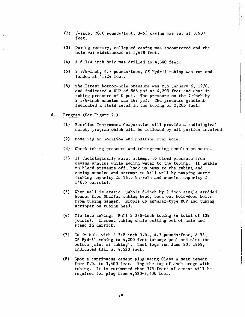
(2) 7-inch, 20.0 pounds/foot, 5-55 casing w a s set a t 3,907 f e e t .
(3) During r een t ry , col lapsed casing w a s encountered and t h e h o l e w a s s ide t r acked a t 3,678 f e e t .
(4) A 6 1/4-inch ho le w a s d r i l l e d t o 4,600 f e e t .
( 5 ) 2 3/8-inch, 4.7 pounds/foot, CS Hydri l tubing w a s run and landed a t 4,224 f e e t .
(6) The latest bottom-hole p re s su re was run January 6, 1976, and i n d i c a t e d a BHP of 866 p s i a t 4,205 f e e t and shut-in tubing p res su re of 0 p s i . The p res su re on t h e 7-inch by 2 3/8-inch annulus w a s 167 p s i . The p res su re g rad ien t i n d i c a t e d a f l u i d level i n the tubing of 2,205 f e e t .
d . Program (See F igu re 7.)
Ebe r l ine Instrument Corporation w i l l provide a r a d i o l o g i c a l s a f e t y program which w i l l be followed by a l l p a r t i e s involved.
Move r i g on l o c a t i o n and p o s i t i o n over ho le .
Check tubing p res su re and tubing-casing annulus p re s su re .
I f r a d i o l o g i c a l l y s a f e , a t tempt t o bleed p res su re from c a s i n g annulus while adding w a t e r t o t h e tubing. I f unable t o bleed p res su re o f f , hook up pump t o t h e tubing and cas ing annulus and at tempt t o k i l l w e l l by pumping water ( tubing capac i ty is 16.5 b a r r e l s and annulus capac i ty is 146.5 b a r r e l s ) .
When w e l l i s s t a t i c , unbol t 6-inch by 2-inch s i n g l e studded bonnet from Shaffer tubing head, back ou t hold-down b o l t s from tubing hanger. s t r i p p e r on tubing head.
Nipple up annular-type BOP and tubing
T i e i n t o tubing. P u l l 2 3/8-inch tubing (a t o t a l of 139 j o i n t s ) . In spec t tubing while p u l l i n g o u t of h o l e and s t a n d i n d e r r i c k .
G o i n ho le with 2 3/8-inch O.D., 4.7 pounds/foot, 5-55, CS Hydri l tubing to 4,200 f e e t (orange p e e l and s l o t t h e bottom j o i n t of t ub ing ) . L a s t l ogs run June 23, 1968, i n d i c a t e d f i l l a t 4,520 f e e t .
Spot a continuous cement p lug using Class A nea t cement from T.D. t o 3,400 f e e t . tubing. r equ i r ed f o r plug from 4,520-3,400 f e e t .
Tag t h e top of each s t a g e with It is est imated t h a t 375 f e e t 3 of cement w i l l be
29

l794'W -=',
30
. . ~ . ....... . .. . .

(9) Af t e r tagging cement plug a t t 3,400 f e e t , c i r c u l a t e hole t o su r face with water.
(10) P u l l 2 3/8-inch tubing from ho le l ay ing down s a m e u n t i l a depth of 600 f e e t i s reached. Spot a cement plug of Class A n e a t + 2 percent C a C 1 2 from 600 f e e t t o 350 f e e t . Inside. 7-inch casing ( r e q u i r e s 55 f e e t 3 of cement s l u r r y ) , p u l l up t o 200 f e e t and w a i t u n t i l cement is set . Tag t h e t o p of the. cement plug with tubing, p u l l ou t of ho le l a y i n g down tubing. Spot a s u r f a c e plug i n s i d e 7-inch c a s i n g us ing Class A n e a t cement from 15 f e e t t o surface. Place 4-inch-diameter ho le marker p i p e i n t o top plug such t h a t 4 f e e t w i l l p ro t rude above f i n a l ground l e v e l .
(11) Nipple down annular BOP and tubing s t r i p p e r . Remove tubing head and Shaffer manual blowout preventer . Move r i g o f f l oca t ion .
NOTE: The 9 5/8-inch and 7-inch cas ing s t r i n g s w i l l be c u t o f f a t t h e bottom of t h e cel lar , t h e CMP removed, and cel lar b a c k f i l l e d with d i r t a f t e r t h e r i g has moved o f f l o c a t ion.
3. W e l l GB-3
a. Location: 1,430' S, 1,636' W Sect ion 36, T 29 N , R 4 W Rio Arr iba County, New Mexico
Ground Elevat ion: 7,201 f e e t
b. Type Hole: Postshot T e s t Well
c. P resen t Conditions (See Figure 8.)
(1) 9 5/8-inch 32.0 pounds/foot, H-40 cas ing i s set a t 538 f e e t and cemented t o t h e su r face .
(2 ) 7-inch, 20.0 pounds/foot, 5-55 cas ing i s set a t 3,791 f e e t w i t h t o p of cement i n 7-inch x 8 3/4-inch annulus a t 2,120 f e e t .
(3) A 4 1/2-inch, 10.5 pounds/foot, K-55 l i n e r i s set w i t h bottom a t 4,809 f e e t and t o p a t 3,743 f e e t . The l i n e r i s pe r fo ra t ed a t following i n t e r v a l s : 3,922-34 f e e t , 3,988- 4,000 f e e t , 4,045-66 f e e t , 4,120-32 f e e t , 4,188-4,200 f e e t (one s h o t pe r f o o t ) . The l i n e r w a s n o t cemented.
(4) A 2 3/8-inchY 4.6 pounds/foot, 5-55 tub ing s t r i n g was run and hung i n tubing head with bottom at 4,190 f e e t .
31

I O 0 0
2000
BURNS UUR ub)r16f% AT 3743'
. . . . .. .. ..... .~ -

(5) The la tes t bottom-hole pressure survey run January 6 , 1976, i n d i c a t e s a p res su re of 580 p s i a t 4,179 f e e t wi th a shut- in tub ing p res su re of 28 p s i and cas ing p res su re of 510 p s i . The p res su re g rad ien t i n d i c a t e s a f l u i d level of 2 2,900 f e e t i n t h e tubing.
d . Program (See F igure 9.)
Ebe r l ine Instrument Corporation w i l l provide a r a d i o l o g i c a l s a f e t y program which w i l l be followed by a l l p a r t i e s involved.
Check wellhead pressure , measure and record same on both tub ing and casing. Have Eber l ine perform r a d i o l o g i c a l check on w e l l e f f l u e n t . I f e f f l u e n t is r a d i o l o g i c a l l y s a f e , a t tempt t o bleed p res su re o f f .
I f e f f l u e n t is unsafe o r i f unable t o bleed p res su re o f f tub ing and cas ing , hook up r i g pump t o tubing and cas ing and k i l l w e l l by "bullheading" water down cas ing and tubing. Tubing capac i ty is 16.3 b a r r e l s and annulus capac i ty i s 140 b a r r e l s . It may be necessary t o pump twice o r t h r e e t i m e s t h i s capac i ty t o k i l l t h e w e l l . U s e a l igh tweight n a t i v e o r ben ton i t e mud t o k i l l w e l l i f a t tempts wi th water f a i l .
Unbolt wellhead above tubing head a t 6-inch x 2-inch s i n g l e studded bonnet. tub ing head and tubing s t r i p p e r on top of BOP adding water t o tubing and cas ing while working on wellhead t o prevent any repressur ing .
Nipple up annular-type BOP on top of Continue
Back ou t hold-down b o l t s , p u l l 2 3/8-inch, 4.6 pounds/foot, 5-55 tub ing l ay ing down same. Eber l ine w i l l r a d i o l o g i c a l l y check tubing. It w i l l be decided a t t h i s t i m e i f decontamina- t i o n ope ra t ions of tubing w i l l be requi red . Keep ho le f u l l whi le p u l l i n g tubing.
G o i n t h e ho le p ick ing up a s t r i n g of 2 3/8-inch O.D., 4.7 pounds/foot, 5-55, Hydr i l tub ing open ended t o t o t a l depth of 4 ,809 , f ee t . This s t r i n g w i l l be comprised of tubing from both GB-2RS and GB-3.
Rig up cement t r u c k and s p o t a cement plug i n s i d e 4 1/2-inch l i n e r and 7-inch cas ing from t o t a l depth t o 3,400 f e e t us ing Class A n e a t cement mixed t o 15.6 ppg wi th f r e s h water. Th i s plug can be set i n a continuous s t a g e as long as t h e cement cont inues t o rise. Tubing must be pu l l ed while cementing t o keep t h e bottom of t h e tubing approximately a t t h e top of t he cement.
Approximately 350 f e e t 3 of cement w i l l be requi red .
Flush tubing wi th water and p u l l up above c a l c u l a t e d cement top approximately 200 f e e t . s u r f a c e sample has set.
Wait on cement u n t i l Tag top of plug wi th tubing.
I 33

.. .... ".. ..
-2ztE I

(9) After tagging plug, c i r c u l a t e water t o s u r f a c e using cement pump truck. P u l l ou t of ho le s tanding 500 f e e t of tubing i n t h e d e r r i c k and l a y i n g t h e remainder down.
(10) Rig up e lectr ic l i n e and p e r f o r a t e t h e i n t e r v a l 600-604 f e e t w i t h 4 HPF. Rig down e lec t r ic l i n e .
(11) Close annu la r BOP and at tempt t o c i r c u l a t e water down t h e 7-inch casing and ou t t h e 9 5/8-inch x 7-inch annulus valve. I f a b l e t o c i r c u l a t e , go i n t h e ho le wi th 2 3/8-inch tubing t o 2 250 feet and c l o s e annular BOP around tubing.
I (12) Rig up cement t r u c k and c i r c u l a t e cement u n t i l cement r e t u r n s are observed a t t h e 9 5/8-inch x 7-inch annulus valve. f e e t . cement i s set. pe rcen t C a C 1 2 w i l l be required.
Displace cement o u t of tubing i n t o cas ing t o 350 Hold p res su re on tubing t o prevent backflow u n t i l
An est imated 200 f e e t 3 of Class A + 2
(13) Tag t h e top of t h e cement plug wi th tubing. h o l e l a y i n g down tubing. 7-inch cas ing from 15 f e e t t o surface. P l ace 4-inch- diameter ho le marker p ipe i n t o top plug such t h a t 4 fee t w i l l protrude above f i n a l ground level.
P u l l out of Spot a s u r f a c e plug i n s i d e of
(14) Nipple down tubing s t r i p p e r and annular BOP. Remove tubing head. Move r i g o f f l oca t ion .
NOTES :
I f unable t o c i r c u l a t e cement around o u t s i d e of 7-inch casing, p e r f o r a t i o n s 600-604 f e e t w i l l be squeezed and 7-inch casing p e r f o r a t e d a t bottom of 9 5/8-inch casing (+ 528 feet) . w i l l then be c i r c u l a t e d t o s u r f a c e using a similar procedure.
Cement
The 9 518-inch and 7-inch casing s t r i n g s w i l l be cut off at the bottom of t h e cellar, t h e CMP removed, and cel lar b a c k f i l l e d w i t h d i r t a f t e r t h e . r i g has moved o f f l oca t ion .
4. Well GB-ER
a , Location: (Surface) 1,218' FSL, 1,770' FWL Sect ion 36, T 29 N,, R 4 W Rio Arr iba County, New Mexico
Ground Elevat ion: 7,204 f e e t
b. Type Hole: Postshot Reentry of Emplacement Hole
c. P resen t Conditions (See Figure 10.)
A 28-inch emplacement ho le w a s d r i l l e d t o 4,350 f e e t . (1)
35

-3407' - dtclpc - 3562' -
FkSltFE IO 36

(2) 20-inch O.D., 133 pounds/foot and 160 pounds/foot casing w a s run t o 4,350 f e e t and cemented back t o sur face .
(3) The device w a s run on 4,227 f e e t on 26 pounds/foot, N-80, 8rd , LT&C cas ing with cables a t tached t o the casing.
(4) The ho le w a s reentered a f t e r t h e . s h o t and 7-inch cas ing destemmed t o 3,916 f e e t . The chimney w a s encountered a t 3,907 f e e t .
( 5 ) A Baker Model D packer with f l appe r valve w a s set a t 3,876 f e e t and 119 j o i n t s of 2 7/8-inch, 6.5 pounds/foot, EUE, 8 rd tubing w a s run and landed i n t h e packer.
(6) The la tes t bottom-hole pressure survey run w a s January 6, 1976. and a gas g rad ien t t o 3,790 f e e t with a p res su re of 473 p s i a t 3,790 f e e t . annulus had no pressure .
It i n d i c a t e s a shut- in tubing p res su re of 425 p s i
The 7-inch casing by 2 7/8-inch tubing
(7) At t h e present time, the re is an obs t ruc t ion i n the tubing 8 f e e t below the top master valve.
d . Program (See Figure 11.)
(1) Eber l ine Instrument Corporation w i l l provide a r a d i o l o g i c a l s a f e t y program which w i l l be followed by a l l p a r t i e s involved.
(2) The f i r s t ob jec t ive is t o e s t a b l i s h the n a t u r e of and remedy f o r t he tubing obs t ruc t ion . p r i o r t o moving t h e r i g over t h e w e l l as fo l lows:
(a )
This may be accomplished
Rig up a w i r e l i n e u n i t with l u b r i c a t o r f o r 2 7/8-inch EUE, 8rd top tree connection.
(b) Run an impression block and w i r e l i n e t o o l s t r i n g us ing t h e l u b r i c a t o r t o determine t h e n a t u r e of t h e obs t ruc t ion . The obs t ruc t ion is be l ieved t o be an impediment r a t h e r than col lapsed tubing s ince t h e r e are no e x t e r n a l stresses a t t h i s po in t i n t h e tubing s t r i n g .
(c) I f t h e impression block i n d i c a t e s t h a t t h e obs t ruc t ion i s fo re ign matter, run t h e guage c u t t e r and jars, and remove t h e impediment or j a r i t downhole. above the obs t ruc t ion should be equal ized t o 425 p s i u s ing a hand pump before j a r r i n g .
The p res su re .
(3) After the obs t ruc t ion i s removed, t he guage c u t t e r should be run t o t h e top of t h e packer t o a s su re t h a t t h e tubing is c l e a r .
37

-8Wf- -9w'-
SLOTS
l47Ll I-
-1536,- /
*--IS 78 -

Move the r i g up over t he w e l l .
Check p res su re on both tubing and 7--nch cas ing annulus.
Hook up r i g pump t o 7-inch x 2 7/8-inch annulus and at tempt t o f i l l annulus wi th water. p s i t o test packer seals on annulus s i d e .
Pressure up on annulus t o 200
Disconnect from cas ing annulus and r i g up pump t o 2 7/8-inch tubing. Pump t h r e e t i m e s t h e capac i ty of t h e tubing ( 2 68 b a r r e l s ) of water. p re s su re . Record t h e t i m e i n t e r v a l between pump shutdown and tubing p res su re bui ldup. I f poss ib l e , cont inue adding water t o prevent any tubing p res su re buildup.*
Shut pump down and monitor tubing
Rig up electric l i n e u n i t wi th grease seal l u b r i c a t o r and 3/16-inch l i n e . 3,876 f e e t . and set a t approximately 10 f e e t above t h e packer. Attempt t o keep tubing f i l l e d wi th water while running b r idge plug. The br idge plug is run with a Baker Model E-4 w i r e l i n e p r e s s u r e s e t t i n g assembly. P u l l w i r e l i n e from ho le and r i g down l u b r i c a t o r .
Run c o l l a r l o c a t o r and t i e i n packer a t Run a Baker Model P-1 w i r e l i n e b r idge plug
F i l l tubing wi th water and test br idge plug wi th 200 p s i s u r f a c e p re s su re ( tub ing capac i ty is 21.8 b a r r e l s ) .
Disconnect f low l i n e from tree and decontaminate same. Unbolt bonnet above Cameron tubing head and back out hold-down b o l t s on tubing hanger. tree removed.
Decontaminate upper p o r t i o n of
Nipple up Hydri l annular BOP on top of tub ing head wi th a tub ing s t r i p p e r on top of t h e Hydri l .
T i e i n t o tub ing .head wi th a j o i n t of 2 7/8-inch tubing. Rig up electric l i n e and cu t 2 7/8-inch tubing using j e t c u t t e r 2 1 0 f e e t above br idge plug.
Hook up pump to tubing and c i r c u l a t e ho le wi th water. Observe i f ho le w i l l s tand f u l l of w a t e r .
Rig up cement t r u c k and spo t 125 f e e t 3 of tubing on top of tub ing s tub . The top of t h e cement should be a t 3,300 feet. l o g t o determine the top of t h e cement.
P u l l tubing up t o 3,000 f e e t and run a f l u i d dens i ty
I f cement is i n p l ace and no t dropping, p u l l ou t of t he h o l e l a y i n g down 2 7/8-inch tubing. Tubing w i l l have t o be decontaminated o r t r anspor t ed t o an approved d i sposa l s i t e .
*Accumulated f l u i d s from t h e s u r f a c e f a c i l i t i e s decommissioning work (see Sec t ion V1.A. and B.) should be i n j e c t e d down t h e GB-ER tubing a t t h i s t i m e .
39

(16) Go i n t h e ho le picking up a s t r i n g of 3 1/2-inch, 13.3 pounds/foot, 3 1/2-inch IF, Grade E d r i l l p ipe , a s e c t i o n m i l l f o r 7-inch, 26.0 pounds/foot cas ing and t en 4 3/4-inch O.D.,, 3 1/2-inch IF d r i l l c o l l a r s . b lade x 4 3/4-inch body s t a b i l i z e r j u s t above t h e s e c t i o n m i l l and one s t a b i l i z e r one j o i n t up from m i l l .
Space one 6 1/8-inch
(17) Rig up mud c i r c u l a t i n g system wi th f i n e screen shaker f o r removal of metal c u t t i n g s . condi t ion ho le wi th l igh tweight 8.5-9.0 pounds/gallon h igh-v iscos i ty mud (80-100 seconds). M i l l a 20-foot s e c t i o n i n 7-inch cas ing from 2 3,250-3,270 f e e t . M i l l w i l l have a 5 7/8-inch body O.D. and 3 1/2-inch API r egu la r p in top c 0Me.C t ion.
Go i n ho le t o 2 3,250 f e e t and
(18) C i r c u l a t e ho le c lean, p u l l and l a y down 3 1/2-inch d r i l l Pipe-
(19) Go i n t h e ho le picking up 2 3/8-inch O.D., 4.7 pounds/foot, 5-55, EUE, 8rd tub ing t o top of cement a t 3,300 f e e t . Plug back hole w i t h cement f r o m 3,300 feet to bottom of cellar. Use Class A n e a t cement. This should be done i n a continuous s t a g e p u l l i n g 180 f e e t of p ipe f o r every 40 f e e t 3 of cement pumped. back from 3,300 f e e t t o t h e bottom of t h e c e l l a r .
710 f e e t 3 of cement should be required t o plug
(20) Remove annular BOP, tubing head, and cas ing head. Decon- taminate necessary components of w e l l head.
(21) Move r i g o f f l oca t ion .
NOTE: 30-inch, 20-inch, and 7-inch casing s t r i n g s w i l l be c u t of f a t t h e bottom of t h e cellar, a steel p l a t e welded on top of t h e 20-inch cas ing , CMP removed, cellar b a c k f i l l e d wi th d i r t , and ho le marker/monument placed i n accordance wi th Sect ion V1.E. a f t e r r i g i s moved o f f l oca t ion .
5 . Well GB-D
a. Location: (Surface) 2 1,500' S 37O E of GB-ER
Sect ion 36, T 29 N , R 4 W Rio Arr iba County, New Mexico
Ground Elevat ion: 7,208 f e e t
b. Type Hole: Preshot Ground Motion Measurement
40

c . P resen t Condi t ions (See Figure 12.)
(1) 20-inch, 133 pounds/foot cas ing is set a t 29 f e e t and cemented t o sur face .
(2) 1 3 3/8-inch, 48 pounds/foot cas ing is set a t 482 f e e t and cemented t o s u r f ace.
(3) A 1 2 1/4-inch ho le w a s d r i l l e d t o a t o t a l depth of 4,725 f e e t .
(4) A messenger cable wi th four instrument packages w a s run. Instruments are loca ted on ind iv idua l cab le a t 3,250 f e e t , 3,600 f e e t , 4,218 f e e t , and 4,600 f e e t .
(5) The ho le w a s cemented from T.D. t o 3,106 f e e t .
d. Program (See F igure 13.)
Ebe r l ine Instrument Corporat ion w i l l provide a r a d i o l o g i c a l s a f e t y program which w i l l be followed by a l l p a r t i e s involved.
Move r i g on l o c a t i o n and r i g up.
Remove wellhead p l a t e from 13 3/8-inch cas ing without damaging t h e messenger o r instrument cables . (There are f o u r instrument cab le s a t t ached t o t h e messenger cab le . Each instrument cable is 1-1 1 / 4 inches i n diameter ; t he messenger cab le i s 1/2-inch wire wrapped.)
Rig up on electric l ine u n i t and a run a depth check, u s ing s i n k e r b a r s , t o 2 620 f e e t .
F a b r i c a t e a guide us ing a s h o r t l eng th of 7-inch cas ing which w i l l be s l i p p e d over the bundle of cables.
Attach t h e guide t o t h e electric l i n e and run i n the ho le over t he cab le bundle t o 600 f e e t .
I f d ry run wi th f a b r i c a t e d guide is success fu l , run i n wi th p l a s t i c explos ive and blow cables a p a r t a t 600 f e e t . Measure footage of cab le s pu l l ed from ho le ( p u l l t ens ion i n cab le s when blowing a p a r t ) .
Go i n ho le p ick ing up 2 3/8-inch, 4.7 pounds/foot, 5-55 tubing t o 600 f e e t .
Mix and spot a cement plug of Class A nea t + 2 percent CaC12 from 600 f e e t t o 350 f e e t . , P u l l tubing up t o 2 200 f e e t . F lush wi th 5 b a r r e l s water, w a i t on cement t o se t , and then t a g top of plug wi th tubing.
4 1

WELCNO. 66-0 azumr ~ R ~ S D \ P I O ~
I O 0 0
2000
3oUo
4000
5000
.' rb%' - 1
l*'W Ib 432'
-4
- MUD
FwURE I 2
42
- - - . . - - . . - - . . . . . . . . . . .. - . . . . ._ . . . . . - -.

1000 -
2000 -
W T D
-0 -
4000 -
H.
A.
B.
F&S
A.
I ,
(10) A f t e r tagging plug, p u l l o u t of ho le l a y i n g down tubing. Spot a s u r f a c e plug using Class A n e a t from 15 f e e t to ground level. P l ace 4-inch-diameter ho le marker p ipe i n t o t o p plug such t h a t 4 f e e t w i l l protrude above f i n a l ground 1 eve1 .
(11) Rig down and prepare t o move.
- NOTE: The 20-inch cas ing s t r i n g s w i l l be c u t o f f a t t h e bottom of t h e cellar, t h e CMP removed, and cellar b a c k f i l l e d with d i r t a f t e r t h e r i g has moved o f f .
Salvable Wellhead Components
It is expected t h a t a l l wellhead components w i l l be s u c c e s s f u l l y decon- taminated, a l lowing t h e i r release f o r u n r e s t r i c t e d use. The Government- owned components l i s t e d i n Appendix D w i l l be placed i n a designated holding area f o r r e t u r n t o t h e Nevada T e s t S i t e . The EPNG-owned components, i .e . , t hose no t l i s t e d i n Appendix D, w i l l be placed i n t h e designated EPNG materials holding area.
V I I . PUBLIC INFORMATION
News Releases
The DOE/NV O f f i c e of P u b l i c A f f a i r s and EPNG w i l l i s s u e a j o i n t pub l i c announcement regarding t h e r e s t o r a t i o n work approximately one week be fo re F&S seeks approval of t h e w e l l plugging and abandonment procedures and ano the r announcement upon completion of f i e l d ac t iv i t ies .
Ind iv idua l Correspondence
Appropriate s ta te and l o c a l o f f i c i a l s w i l l be s e n t a copy of t h e f i r s t pub l i c announcement via t r a n s m i t t a l let ter be fo re release t o t h e gene ra l news media.
V I I I . REPORTS
and Eber l ine w i l l submi t .pe r iod ic and f i n a l r e p o r t s as i d e n t i f i e d below.
F&S .
1. Daily Work P rogres s Report: An informal r e p o r t w i l l be submitted t o t h e P r o j e c t Engineer a t t h e end of each workday. The r e p o r t w i l l c o n s i s t of a handwritten summary n a r r a t i v e of w e l l plugging and abandonment ope ra t ions and gene ra l support work. The r e p o r t w i l l con ta in information p e r t i n e n t t o t h e f i e l d ope ra t ions of t h a t day.
2 . Weekly Cost S t a t u s : This r e p o r t w i l l include a l l c o s t s incurred during t h e preceding workweek and w i l l be submitted t o t h e P r o j e c t Engineer on t h e f i r s t workday fol lowing t h e r e p o r t i n g week.
44
. . . , . . . - . . - .. -..I

3. F i n a l Report: t i o n act ivi t ies and record t h e s i te s t a t u s a t p r o j e c t conclusion. Included w i l l be f i n a l d i s p o s i t i o n of a l l materials and equipment and an a s - b u i l t s t a t u s of a l l plugged and abandoned w e l l s .
This r epor t w i l l summarize a l l abandonment and r e s t o r a -
4. Other: Mexico, O i l Conservation Commission, t he USGS, and t h e U.S. Fo res t Service.
F&S w i l l provide a l l r e p o r t s r equ i r ed by t h e S t a t e of New
B. Ebe r l ine
1.
2.
3.
Da i ly Work Progress Report: An informal r e p o r t w i l l be submitted t o t h e P r o j e c t Engineer through t h e ROS a t t h e end of each workday.
'The r e p o r t w i l l c o n s i s t of a handwritten summary n a r r a t i v e of radio- l o g i c a l ope ra t ions f o r t h a t day. S i g n i f i c a n t p rogres s made o r major problems encountered should be highl ighted.
Weekly Cost S t a t u s Report: l a b o r a t o r y support c o s t s incurred f o r r a d i o l o g i c a l work during t h e preceding workweek. format t o t h e P r o j e c t Engineer on t h e f i r s t workday following t h e r e p o r t i n g week.
This r e p o r t w i l l include f i e l d c o s t s and
The r e p o r t w i l l be submitted i n a DOE-prescribed
Radiat ion Contamination Clearance Report: This r e p o r t w i l l summarize a l l s i te r e s t o r a t i o n r a d i o l o g i c a l a c t i v i t i e s , d e s c r i b e f i n a l s i te r a d i o l o g i c a l cond i t ions , and con ta in o the r information as required by DOEM Appendix 5301. The r e p o r t s h a l l be due i n d r a f t form 45 days a f t e r conclusion of f i e l d operat ions. The procedure f o r review and pub l i ca t ion of t h e r e p o r t i n f i n a l form w i l l be s t i p u l a t e d i n t h e DOE/Eberline con t r ac t .
I X . SURVEILLANCE PROGRAM
I n accordance w i t h DOE, po l i cy , a long-term hydrologic monitoring program has been e s t a b l i s h e d f o r t h e Gasbuggy site. The ongoing program, conducted by the Environmental P r o t e c t i o n Agency (EPA), c o n s i s t s of annual sampling and ana lyses of waters f o r t r i t i u m and o t h e r r ad ionuc l ides i n t h e P r o j e c t Gasbuggy area. The elements of t he sampling program are as follows:
A. Sampling Network (See Figure 14. )
The fol lowing sampling p o i n t s were s e l e c t e d as being r e p r e s e n t a t i v e of water s u p p l i e s i n the Gasbuggy area:
1. Wells
a. EPNG, Well #10-36* b. Windmill 112 c. Lower Burrow Canyon
Approx. Distance From Surface Ground Zero (SGZ)
450 f e e t (on si te) 4 miles 7 miles
*EPNG h a s ind ica t ed a d e s i r e t o P&A t h i s w e l l concurrent ly w i t h the s i te r e s t o r a t i o n a c t i v i t i e s and it s h a l l t h e r e f o r e be el iminated from t h e Long-Term Surve i l l ance program un les s agreement can be obtained from EPNG t o d e f e r P&A.
45

T30N
T29 N - ~
T.28N
R. SW
To Formingion -1 To B l o n c o (Son Juon R i v e r ) \
OBixkr Ranch I / - - 'UHsll
Jicarilla Apoche - R e s rvotion We! I
A 8
O C o v e Spring
Res zrvat ion W e I I
T.27N
0 WELL
0 SURFACE SAMPLING 0 I 2 3 4 5 K M . POINTS.
'MI.
Figure14 UING TERM WATER SAMPLING NETWORK
46
. . . . I

Wells - d. Bixler Ranch e. Jicarilla Apache Res.
(South Well) f. Jicarilla Apache Res.
(No r t h We 1 1 )
2. Surface Waters
a. Cave Spring b. Bubbling Spring c. Arnold Ranch d. La Jara Creek
Approx. Distance From Surface Ground Zero (SGZ)
7 miles
6 miles
6 miles
4 miles 5 miles 8 miles 3 miles
Samples are collected annually from the above locations. scheduled to continue indefinitely.
The program is
B. Analyses 0 The depth to water (head), temperature in C., pH, and electrical conduc-
tance are recorded at the time of collection. All samples are analyzed for gross alpha and gross beta radioactivity and for gamma-emitters by gamma spectroscopy. All samples are analyzed for tritium, first by the conventional method for the purpose of screening, and then those samples having concentrations less than the minimum detectable concentration are analyzed by the enrichment method.
Based on the results of these analyses, any suspect samples will be analyzed for additional appropriate specific naturally occurring or man-made radionuclides.
C. Reports
The EPA Environmental Monitoring and Support Laboratory, Las Vegas (EMSL-LV), shall prepare annual reports which contain the following:
1. Description of the sampling. network,
2 . Results, with a comment on analytical techniques used and degree of accuracy achieved.
3 . Interpretation of results.
4 . Evaluation of the monitoring program with suggested modifications for its improvement.
X. SCHEDULE
Figure 15 depicts the schedule for abandonment of the Project Gasbuggy site.
47

PROJECT GASBUGGY S I T E RESTORATION SCHEDULE
ACTlV ITY
A.PREF! PLAN e COST ESTIMATE- - - -
B.PLAN REVIEW 8 APPROVAL - - - - C.RECElVE FUNDING - - - - - - D-EXECUTE CONTRACTS - - - - - - E.PERMlTS (PeA,MISC. ) - - - - - - F.F lELD EXECUTION - - - - - - -
I. MOBILIZE - - - - - - - - 2. CONSTRUCT DECON SYSTEM - - - 3. SURF. FACIL. DISMANTLE/DECON - - 4. PLUG AND ABANDON WELLS - - -
0. G B - l - - - - - - - b. G B - 2 - - - - - - - c. G 6-3------- d- G B - D - - - --- - e. G B - E - - - - - - -
5. WELLHEAD COMPONENTS DECON - - 6. BREAK UP 8 BURY CONC. PAD - - - 7. MATERIALS REMOVAL - - - - 8. BACKFILL DECON PIT - - - - - 9. SOIL SAMPLE 8 ANALYZE - - - -
IO. FENCE REMOVAL - - - - - - I I. MONUMENT - - - - - - - 12.RESEED - - - - - - - - 13. DEMOBILIZE - - - - - - -
G. F INAL REPORTS - - - - - - -
FIGURE I5
- MAR
. - -I- - ' - - - t - -
~
JUNE 1978 -
SEPT - OCT - NOV -
I
- FEB -

APPENDIX A
ENVIRONMENTAL CONSIDERATIONS

APPENDIX A
ENVIRONMENTAL CONSIDERATIONS
1.
2.
In t roduct ion
The environment a t t h e Gasbuggy s i te endured some stress i n t h e pas t from t h e cons t ruc t ion and nuc lear t e s t i n g a c t i v i t i e s i n 1967 and t o a lesser ex ten t during t h e gas production t e s t i n g i n 1968-1969 and 1973. t h e a c t i v i t i e s and procedures proposed i n Sec t ion V I of t h i s p l an are i n f a c t m i t i g a t i n g measures intended t o achieve environmental b e n e f i t s . cleanup of t h e s i t e and t h e removal and s a f e d i sposa l of any contaminants, equipment and f a c i l i t i e s remaining wi th in t h e fenced Gasbuggy compound are intended t o erase any i n s u l t s t o t h e environment which s t i l l e x i s t s from p a s t a c t i v i t i e s . Plugging of a l l t e s t - r e l a t e d d r i l l ho les is a l s o intended t o p r o t e c t a g a i n s t p o t e n t i a l environmental hazards which otherwise might occur i n t h e f u t u r e . Even though t h e s e a c t i v i t i e s are intended t o produce a n e t enhancement t o t h e environment, they cannot be accomplished without some d i s tu rbance t o t h e environment which exists today. This appendix cons iders t h e s i g n i f i c a n c e of t h e impacts ensuing from t h e proposed cleanup a c t i o n i n order t o determine i f f u r t h e r environmental documentation is necessary.
Pr imar i ly
The
The Ex i s t ing Environment
Sec t ion I1 and Sec t ion V.B., of t h i s p lan have descr ibed t h e environment and t h e r ad io log ic condi t ions as they e x i s t today. f a c t o r s need t o be considered t o eva lua te t h e . p o t e n t i a 1 environmental stresses.
Several a d d i t i o n a l
a. Bioenvironmental Factors :
Vegetat ion i n t h e surrounding areas cons is t s p r imar i ly of pizon p ine i n t h e lower l e v e l s and ponderosa p ine and jun ipe r i n t h e higher e l eva t ions . The v a l l e y f l o r a c o n s i s t s p r i n c i p a l l y of sage and chamisa ( rabbi tbush) . Natural r evege ta t ion of fo rbes and g ras ses has taken p l ace i n areas previous ly d is turbed . Q the r vege ta t ion r e s u l t s from t h e grading and seeding which has taken p l ace i n t h e p a s t , as noted i n Sec t ion I1 of t h i s plan.
Resident fauna c o n s i s t s of muledeer, coyotes , r a b b i t s , porcupines, several spec ie s of ground s q u i r r e l s and o the r rodents , b i r d s , rep t i les and i n s e c t s . I n c e r t a i n seasons, bobcat, cougar, and migratory b i r d s such as dove and waterfowl can be seen i n t h e area. than t h e r a b b i t are excluded from t h e Gasbuggy s i t e s i n c e t h e surround- ing fence has r e s t r i c t e d t h e i r eg res s f o r nea r ly a decade.
Animals l a r g e r
No formal i n v e s t i g a t i o n of t h e ex i s t ence of threatened and endangered spec ie s has been conducted a t t h e s i te . L i s t s of such proposed spec ie s have been published i n t h e Federa l Regis te r (40 FR 27823-27924, J u l y 1, 1975 and 40 FR 24523-24572, June 16, 1976).

P a s t actionswhich have taken p l a c e inc lude t h e cons t ruc t ion of roads, off-road t r a f f i c , c o n s t r u c t i o n of f a c i l i t i e s , i n s t a l l a t i o n of trailer parks , etc. I f rare and endangered s p e c i e s d id exist i n t h i s area previous t o t h e a c t i o n s which have taken p l ace i n t h e p a s t , t h e i r s u r v i v a l i s u n c e r t a i n i n t h e d i s tu rbed areas.
b. Archaeological and H i s t o r i c C u l t u r a l S i t e s :
For several y e a r s r e l a t i v e l y i n t e n s e ac t iv i t i e s have been conducted a t t h e Gasbuggy s i t e by a cons ide rab le number of p r o j e c t people. During t h i s time, no evidence of a rchaeo log ica l o r h i s t o r i c c u l t u r a l sites has been found and r epor t ed w i t h i n t h e areas under considera- t i o n f o r t h i s proposed a c t i o n .
c. A i r Quality:
A i r q u a l i t y i n v e s t i g a t i o n s have no t been conducted f o r t h e Gasbuggy si te. During t h e Gasbuggy experiment and subsequent s t u d i e s , v i s u a l obse rva t ions ind ica t ed t h a t v i s i b i l i t y w a s c o n s i s t e n t w i th t h a t u s u a l l y encountered i n t h e higher mesa areas of New Mexico. c o n s t r u c t i o n ac t iv i t i e s r e s u l t e d i n no s i g n i f i c a n t i n c r e a s e i n t h e p a r t i c u l a t e a i r b o r n e q u a l i t y beyond t h e s i t e boundaries. During t h e d r i l l b a c k ac t iv i t i e s and t h e gas production t e s t i n g which followed, some 2,250 c u r i e s of tritium and 370 c u r i e s of krypton-85 were r e l eased i n t o t h e atmosphere. Ca re fu l monitoring of personnel and t h e environ- ment by t h e Ebe r l ine Instrument Corp., and t h e U. s. Environmental P r o t e c t i o n Agency (EPA) during a l l ac t iv i t i e s t h r u 1973 ind ica t ed t h a t t h e s e r ad io i so toPes were e i t h e r unde tec t ab le o r so f a r below t h e cri- ter ia c i t e d i n Sec t ion V t h a t no hazards ex i s t ed t o t h e workers on s i t e , nor t o t h e r e s i d e n t s , animals, o r v e g e t a t i o n i n surrounding areas. Since 1973, t h e r e e n t r y w e l l and o t h e r w e l l s have been shut i n , except f o r p e r i o d i c monitoring of p re s su re and f l u i d levels.
Previous
d. Water Qua l i t i e s :
No s u r f a c e streams o r l a k e s exist on o r near t h e si te. The n e a r e s t major s u r f a c e water bodies are t h e San Juan River, about 30 m i l e s t o t h e no r th , t h e Navajo and E l Vado Reservoirs , about 25 m i l e s t o t h e northwest and east, r e s p e c t i v e l y (see F igure 1 . ) La Jara Lake is a small r e s e r v o i r about 1 0 m i l e s east of t h e s i te . The Environmental P r o t e c t i o n Agency (EPA) has c o l l e c t e d , a n d analyzed water samples from w e l l s , sp r ings , streams and ponds a t and near t h e Gasbuggy s i te as p a r t of t h e Long-Term Hydrologic Monitoring Program (see Sec t ionM of t h e plan.)
Throughout t h e area, t h e major c a t i o n s and anions, such as potassium, magnesium, sodium and c h l o r i d e are a t low levels, as are most of t h e trace elements such as l i t h i u m and aluminum. However, a l k a l i n i t y i s high (>lo0 mil l igrams p e r l i ter of calcium carbonate) a_t t h e p o i n t s sampled. La Jara Lake shows higher pH v a l u e s (more a l k a l i n e ) t han do t h e o t h e r p o i n t s sampled.
2

Water q u a l i t y is a problem i n t h e area. l e v e l s are i n excess of water q u a l i t y cri teria f o r dr inking water (EPA) a t most of t h e l o c a t i o n s where samples f o r t h e s e parameters were c o l l e c t e d . Arnold Lakes. f o r i r r i g a t i o n water as w e l l as dr inking water. occas iona l ly i n excess of dr inking water c r i t e r i a .
S u l f a t e s and manganese
S u l f a t e s are p a r t i c u l a r l y h igh a t La Jara and Manganese p e r i o d i c a l l y exceeds recommended cr i ter ia
I ron l e v e l s are
To ta l d i sso lved s o l i d s (TDS) l e v e l s are q u i t e low a t Cave Springs, and moderate a t Bixler Ranch and Bubbling Springs. sampling p o i n t s TDS exceeded 1500 mg/l: e s t ab l i shed c r i t e r i a recommended by EPA f o r TDS, t h e EPA does cons ider that water wi th TDS i n excess of 1000 mg/l w i l l have adverse e f f e c t s on many crops and usage r e q u i r e s c a r e f u l management p r a c t i c e s .
A t a l l o t h e r a l though t h e r e are no
3. P o t e n t i a l Environmental Impacts
The proposed cleanup a c t i v i t i e s which except f o r t h e plugging of t h e w e l l GB-D, w i l l be t o t a l l y contained wi th in t h e 170,000 square f o o t fenced area. It is i n e v i t a b l e t h a t some dus t w i l l be s t i r r e d i n t o t h e a i r by t h e c ranes , d r i l l i n g r i g s , t rucks and o the r v e h i c l e s requi red t o dismount t h e s u r f a c e f a c i l i t i e s , conduct t h e requi red decontamination procedures, t o cement and plug up t h e event r e l a t e d holes and t o remove t h e fencing around t h e per iphery. It is a l s o i n e v i t a b l e t h a t some growing vege ta t ion w i l l be crushed and broken by t h e s e a c t i v i t i e s .
The movement of a d r i l l i n g r i g , cement t r u c k and o the r v e h i c l e s t o and from theGB-D w e l l s i t e w i l l produce t h e same kinds of i n s u l t along a 1500 f o o t t r a i l o u t s i d e of t h e fenced area. The p l an as expressed i n Sec t ion V I c a l l s f o r t h e s e areas t o be reseeded as necessary, as w i l l c e r t a i n areas wi th in t h e s i te i t s e l f . Because t h e land is r e l a t i v e l y f l a t , l i t t l e r e s t o r a t i v e contouring is contemplated and i t w i l l not be eroded by t h e summer r a i n s . The l o s s of h a b i t a t through t h e s e a c t i o n s i s expected t o be minor and temporary, and a f f e c t only a small portion of the faunal community present. The l o s s of h a b i t a t w i th in t h e fenced area w i l l not a f f e c t animals l a r g e r than t h e r a b b i t s i n c e they have been-excluded from t h e s i te f o r nea r ly a decade. A l l of t h e s e e f f e c t s are expected t o be minor as compared t o t h e environmental i n s u l t s which have taken p l ace i n t h e p a s t , and those which have occurred i n t h e pas t have not c r ea t ed any c r i t i c i s m nor adverse opin ions on t h e p a r t of t h e i n t e r e s t e d populat ion. On t h e p o s i t i v e s i d e , when t h e cleanup is accomplished and t h e fence removed, t h e s e few acres (approximately fou r ) w i l l be a v a i l a b l e f o r h a b i t a t and forage by t h e l a r g e r w i l d l i f e spec ies .
The proposed cleanup activit ies w i l l d i s t u r b only a minimal amount of sur- f a c e area which has not been previous ly d i s tu rbed . dangered spec ie s have p e r s i s t e d wi th in t h e s i te o r a long t h e t r a i l lead ing t o t h e GB-D w e l l s i te, they w i l l experience cons iderably less i n s u l t than t h a t which has a l r eady occurred. c u l t u r a l sites have been found o r repor ted i n t h e p a s t it is not expected that t h i s cond i t ion w i l l change.
If any rare and en-
Since no a rchaeologica l o r h i s t o r i c
3

The nearest source of water f o r t h e w e l l plugging and s i te cleanup is a small unnamed r e s e r v o i r about e i g h t m i l e s n o r t h of t h e s i te , h e r e t o f o r e used by EPNG as a water source. planned t h a t water w i l l be t rucked from t h i s source t o t h e s i te . The amount of water used w i l l be less than one percent of t h e capac i ty of t h e r e s e r v o i r and is not considered an excessive expendi ture of a n a t u r a l resource . bu t i n t u r n would r e q u i r e g r e a t e r expendi ture of f u e l .
For t h e proposed cleanup ope ra t ion , i t is
Water could be t rucked from l a r g e r r e s e r v o i r s a t longer d i s t a n c e s ,
Previous s i te surveys have documented t h a t t h e r e i s no r a d i o a c t i v e contamina- t i o n of s o i l o r s u r f a c e water which exceed DOE s i t e d i s p o s a l c r i t e r i a . (See Tables 1 and 2, Sec t ion V of t h i s p lan . ) excess of DOE criteria i s be l ieved l i k e l y on t h e i n t e r i o r s u r f a c e s of t h e gas-production t e s t i n g system, from t h e G B E R w e l l bore tubing, and i n p ip ing through t h e f l a r e s t ack . These items of material and equipment w i l l be surveyed and checked f o r adherence t o t h e r a d i o l o g i c a l cri teria set f o r t h , using t h e procedures s p e c i f i e d i n Sec t ion V.D. I f they f a i l t o m e e t t h e release cr i ter ia they w i l l be decontaminated and remonitored, and a de termina t ion made whether they are s u f f i c i e n t l y clean t o be r e l eased f o r u n r e s t r i c t e d u s e o r r e t a i n e d f o r d i s p o s a l as contaminated waste.
Radioact ive contamination i n
It is planned that t h e water r e s u l t i n g from t h e decontamination ope ra t ions w i l l be c o l l e c t e d i n t h e 500 g a l l o n sump a t t h e end of t h e decontamination pan. contaminated l i q u i d s w i l l be disposed of by i n j e c t i o n i n t o t h e nuc lear chimney r eg ion through t h e GB-ER tubing s t r i n g a f t e r it has been determined that t h e tub ing is c l e a r of o b s t r u c t i o n s . The f l u i d s can be i n j e c t e d under s u f f i c i e n t p re s su re t o overcome any gas p re s su re which may p e r s i s t i n t h e w e l l and sea led a g a i n s t l eakage by a s e c u r e connect ion t o t h e 2-7/8 inch tub ing head va lve . f o r c l e a r i n g and plugging t h e w e l l , t h a t some gas could a c c i d e n t a l l y escape i n t o t h e atmosphere. This gas would con ta in tritium and krypton-85. These ope ra t ions w i l l be c l o s e l y monitored f o r r a d i o a c t i v i t y and can be shut down and t h e w e l l c losed o f f i f i t becomes necessary. The amount of gas which could escape under such cond i t ions would only be a small f r a c t i o n of t h e 400 MMcf of gas which has been r e l eased i n t h e p a s t and would quick ly d i s s i p a t e and d i s p e r s e i n t o t h e atmosphere. E s s e n t i a l l y , no environmental e f f e c t s would r e s u l t i f such a n a c c i d e n t a l release of gas were encountered.
The
It i s p o s s i b l e t h a t dur ing t h i s ope ra t ion o r t h e ope ra t ions
I n summary, t h e proposed cleanup and w e l l plugging a c t i v i t i e s would produce only minor environmental e f f e c t s f o r t h e s h o r t term and would p r imar i ly a f f e c t t h e b i o t a . There w i l l be no s i g n i f i c a n t change i n t h e a i r o r water q u a l i t y i n t h e area. Over t h e long term, however, t h e impact w i l l be t o improve t h e e s t h e t i c a s p e c t s of t h e s i t e by removal of a l l s u r f a c e f a c i l i t i e s , t o m i t i g a t e t h e p o t e n t i a l h e a l t h hazards due t o r a d i o a c t i v e contamination a s soc ia t ed wi th some of t h e f a c i l i t i e s , t o enhance t h e a c c e s s i b i l i t y of t h e s i te t o n a t i v e fauna and o t h e r v i s i t o r s , inc luding humans, and t o c l o s e one of t h e l as t open chap te r s i n t h e Plowshare Program.
The primary na tura l r e sources present below t h e s u r f a c e have been shown t o be l a r g e l y gas and o i l . The excavat ion and d r i l l i n g r e s t r i c t i o n s wi th in a r a d i u s of 100 f e e t of t h e monument w i l l not have any s i g n i f i c a n t i n f luence
4
. . _.._ . . ~ . .

upon t h e f u t u r e recovery of t h e s e resources from t h e area. i t s e l f can become a h i s t o r i c a l marker, enhancing t h e p o t e n t i a l uses of t h e s i t e by t h e U. S. Fores t Serv ice a f t e r i t s release t o t h a t agency.
The monument
It is a n t i c i p a t e d t h a t pe r iod ic r a d i o l o g i c a l monitoring a f t e r t h e s i t e is cleaned up w i l l not be requi red o t h e r than t h e annual water samples taken from Well d 10-36, which w i l l not be plugged, but w i l l cont inue t o be used as p a r t of t h e Long-Range Hydrologic Monitoring Program descr ibed i n Sec t ion X.
4. A l t e r n a t i v e s
The only a l t e r n a t i v e t o t h e proposed a c t i o n is t o t ake no ac t ion . t h e proposed a c t i o n a t Gasbuggy would l eave t h e i n t e r n a l l y contaminated equipment on t h e su r face a t t h e s i te , which i n a d d i t i o n t o t h e p o t e n t i a l hazard, is u n a t t r a c t i v e wi th in t h e surrounding environs. Also, not doing t h e program would not a l low t h e Plowshare s i te t o be used f o r t h e purposes from which it w a s set a s i d e over 1 0 years ago.
Not doing
There i s an a l t e r n a t i v e t o t h e d i sposa l of t h e t r i t i a t e d water which w i l l r e s u l t from decontamination, and which e x i s t s i n a 100-barrel t ank from earlier gas product ion tests. material be i n j e c t e d i n t o t h e w e l l GB-ER before i t is plugged. t i v e is t o s o l i d i f y t h i s l i q u i d and t r a n s p o r t i t t o an approved b u r i a l s i t e , most l i k e l y i n Nevada. Evaporation can be used as p a r t of t h e process f o r s o l i d i f i c a t i o n and w i l l r e q u i r e concurrence from t h e S t a t e of New Mexico a u t h o r i t i e s . volume and expense of t r anspor t ing r a d i o a c t i v e materials over about 700 m i l e s on pub l i c highways. material and not hazardous, t h e psychological impact on t h e publ ic cannot be overlooked.
It i s proposed that t h i s r a d i o a c t i v e l i q u i d An a l t e r n a -
Taking t h i s a l t e r n a t i v e would s i g n i f i c a n t l y inc rease t h e
Even though t h i s would be low-level r a d i o a c t i v e
5. Cumulative and Long-Term Environmental E f f e c t s
A s discussed previous ly , t h e proposed cleanup a c t i v i t i e s are intended t o erase any i n s u l t s t o t h e environment which s t i l l ex i s t ed from pas t a c t i v i - ties. A pool of r a d i o a c t i v i t y formed by t h i s nuclear de tona t ion is trapped i n rock 4,000 f e e t below t h e s u r f a c e and w i l l remain as a long-term conse- quence of t h e experiment. However, because of i t s depth, it w i l l be i s o l a t e d from and out of communication wi th t h e biosphere. r e l a t e d d r i l l ho le s i s intended t o p r o t e c t a g a i n s t poss ib l e environmental hazards which otherwise might occur i n t h e f u t u r e . Except f o r t h e r e s t r i c t i o n s imposed on d r i l l i n g o r excavat ion wi th in t h e 100-foot r a d i u s of t h e monument, t h e s i te w i l l be re turned t o i t s n a t u r a l state. This is intended t o b e . a n end po in t and no o t h e r a c t i v i t i e s are planned by DOE f o r t h e s i te so t h a t no cumulative e f f e c t s beyond t h i s end po in t are a n t i c i p a t e d .
The plugging of a l l test
6. Risk of Credib le Accidents
It is poss ib l e t h a t during disassembly and decontamination of t h e gas t e s t i n g equipment, some cleanup personel may be exposed t o tritium. While t h e levels are not known, and c a r e f u l personnel monitoring w i l l be i n f o r c e , i t i s be- l i e v e d t h a t no dose above t h e s t a t e d cri teria w i l l be accumulated by any in- d iv idua l . I f any tritium conta in ing l i q u i d s were s p i l l e d , assessment and cleanup of t h e s p i l l would be e f f ec t ed promptly.
5

Simi la r ly , i f during t h e t r anspor t ing of low-level r a d i o a c t i v e materials t o a s u i t a b l e r epos i to ry i n Nevada, an acc ident occurred which caused a s p i l l on t h e roadway, some human exposure could arise.
However, t h e low-level r a d i o a c t i v i t y could be s a f e l y and expedi t ious ly cleaned up and any r e s i d u a l d i l u t e d t o less than t h a t permitted i n dr inking water by s u f f i c i e n t f looding wi th uncontaminated water. long-term exposure would be expected from t h i s kind of i nc iden t .
No s i g n i f i c a n t
7. P o t e n t i a l C o n f l i c t s With Land Use and Other Programs
There are no known p lans by l o c a l , s ta te o r o the r Federal agencies which would c o n f l i c t wi th t h e proposed ac t ion . The r e t u r n of t h e land t o U. S . Fores t Serv ice c o n t r o l is c o n s i s t e n t w i th t h e arrangement agreed upon by t h e o r i g i n a l withdrawal order and r ep resen t s a l o g i c a l te rmina t ion of t h e program.
8. Conclusions and Recommendations
Considering t h e environmental s e t t i n g of t h e Gasbuggy s i te and t h e a c t i v i t i e s which l e d t o i t s present condi t ion , a g a i n s t t h e impacts which w i l l accrue i f t h e present cleanup and r e s t o r a t i o n p l an i s implemented, l e a d s t o t h e conclusion t h a t t h e , s i t e and human environment w i l l be improved. I n viewing t h e a n t i c i p a t e d impacts, i t i s obvious t h a t t h e s a f e t y , appearance and u t i l i t y of t h e s i t e w i l l be enhanced over t h e long t e r m , without s i g n i f i c a n t a d d i t i o n a l c o s t t o t h e environment.
It is recommended t h a t because t h e proposed a c t i o n does not c o n s t i t u t e a major Federa l a c t i o n , and w i l l have no s i g n i f i c a n t impact on t h e q u a l i t y of t h e human environment of t h e reg ion , an Environmental Assessment need not be prepared.
6

APPENDIX B
RADIOLOGICAL FIELD OPERATIONS PLAN (To b e suppl ied by Eber l ine)

APPENDIX C
PERMITS AND SUNDRY NOTICES

pom;D-N1 OW. m a
UNITED STATES
GEOLOGICAL SURVEY ' DEPARTMENT OF THE INTERIOR
SUNDRY NOTICES AND REPORTS ON WELLS (00 not use thlr tonn for pmfmsah to drill or to deepen or plug back to a diffemnt w e w o l r . Use Form 9-3314 or such proposals.)
1. oil gas 0 Natu ra l Gas St i rnulat ior #e(l well Other Experiment I n s t r . Hole-
2. NAME OF OPERATOR
9. ADDRESS OF OPERATOR . A D e B t . o f _ E ; n e r P v / E l Paso P a t u r a l Gas Co.
----L U.S. DOE P.O. Box 14100, Las'Vegas,NV 89114 4. LOCATION OF WELL (REPORT LOCATION CLEARLY. See space 17
below.) T-29-N, AT suRFACE~324'FSL,1614'FWL,Sec.36, ~ - 4 4 AT TOP PROD. INTERVAL: AT TOTAL DEPTH: 113.62 'N 60'38 'E of Surf ace
REPORT, OR OTHER DATA 16. CHECK APPROPRIATE BOX TO INDICATE NATURE OF NOTICE,
REQUEST FOR APPROVAL TO: SUBSEQUENT REPORT OF:
TEST WATER SHUT-OFF 0 FRACTURE TREAT 0 SHOOT OR AClDlZE D REPAIR WELL 0 PULL OR ALTER CASING c] El CHANGE ZONES 0 ABANDON' El 0 MULTIPLE COMPLETE n
(other)
Form Approved. . cudget Buroou No. 42-R1424
c 5 1 L 5. LEASE CarsogJ.q-iioni1 P d r e s i -~ -'
6. IF INDIAN, ALLOTTEE OR TRIBE NAME *. ,- ~ L L - I - * IU - '-) -> ,.:, 3
?. UNIT AGREEMENT NAME: 2
Choza Mesa P i c t u r e d C l i f f s 11. SEC., T., R., M., OH ELK. ANDSURVEY
. - .B *. ;- i;; 2 - , ;.! .* - AREA
-- - : --( .
15. ELEVATIONS (SHOW DF, KDB; AND WD) KDB-7215', DF-7214', GL-7203'
17. DESCRIBE PROPOSED d R COMPLETED OPERATIONS (Clearly state al l perti including estimated date of starting any proposed work. If well is directionally drilled, give subsurface locations and measured and true vertical depths for all markers and zones pertinent to this work.)'
1, ? -"5? 2. 3. Unbolt tubing head, p u l l and l a y down 2-3/8" tubing and cab le s . I
4. Go i n h o l e w i t h 2-3/8" tubing and s p o t a 125 f t 3 cement plug 640' t o 350'. Tag t h e t o p of t h e plug w i t h tubing. . -
5. Spot a cement plug from 15' t o t h e bottom of t h e cellar. . I n s 4.0" O.D. p i p e f o r w e l l marker extending from 6' below-ground level- ' t o 4 ' above ground l e v e l w i th top orange peeled and w e 1
Cut 13-3/8" and 9-5/8" cas ing s t r i n g s a t t h e bottom o f t h e cellar
. i_ . :- X 31 Y r. i \ l
T i e i n t o tubing, p u l l t e n s i o n and r u n f r e e p o i n t t o f'640,';' Use p l a s t i c exp los ive t o blow tubing and cables apart at -I 6 4 6 ' . ' Y " ' -1
Well name w i l l be i n s c r i b e d us ing a welded bead.
Remove t h e CMP and b a c k f i l l t he ce l la r w i t h d i r t , - .
- . 6 .
i I.
NOTE: Above o p e r a t i o n s are expected t o be accomplished between 9-1-7'8 .&I> 9-7-78. 5 - 5 Set @ -. L , ' t: Ft. c1 -. ,, Subsurface Safety Valve: Manu. and Type -
ing is true and correct
APPROVED BY CONDITIONS OF APPROVAL, IF ANY:
__ --__ TITLE __
*See lnrtructlons on Reverse Side
I .
v (This space for Federal or State office use)
APPROVED BY __ --__ TITLE __ DATE CONDITIONS OF APPROVAL, IF ANY.
L . I -J&! I&rn 6 I APPROVED I h

- . . . .. . --. . --.-
we11 0 well Other Experiment PS Tes t Wel:. 2. NAME OF OPERATQR
t o m 9931 Form Approved. Doc. 1973 Budget Bureau No. 4 2 4 1 4 2 4
Carson Nat ional Fores t 6. IF INDIAN, ALLOTTEE OR TRIBE NAME
UNITED STATES DEPARTMENT OF THE INTERIOR
GEOLOGICAL SURVEY
.I - I
9. WELL NO. , , .I - - - L . m - l - GB-3 a: -' y z g
. _ I
SUNDRY NOTICES AND REPORTS ON WELLS I UNITAGREEMENTNAME: - - 5 . ' ,.
U.S. Dept . of Energy/El Paso Natural Gas Co. 3. ADDRESS OF OPERATOR U. S . DO& P. 0. Box 14100, Las m a s . NV 8 9 1 1 4 4. LOCATION OF WELL (REPORT LOCATION CLEARLY. See space 17
below.) 1430' FSL, 1636' FWL, Sec. 36,
AT TOP PROD. INTERVAL: AT SURFACE: T-zg-N, R-4-W
I 7 -
~ . . , %J : L:
._ A - Z' - - ' \:
(Do not use thls form for pro resewoir. Use Form 9-3314
sals to drill or to deepen or plug back to a different I 8. FARMORLEASENAME ' such proposals.)
I -- 10. FIELD OR WILDCAT NAME
Choza Mesa Pic tured C l i f f s 11. SEC., T., R., M., OR BLK. AND SURVEY OR
. . - . AREA 4 <
Sec. 36,'T-29-N, R-4-W ' 1 1
Rio Arriba . I New Mexico 12 COUNTY OR PARISH 13. STATE 2.
I- , S ? ; : :i, 1 8 . - . J .. , L ' '.u
: c ' l r r $:> ; '7.?% is true and correct
SIGNED -- TITLE Dip.: F,%FA D i v . DATE -7 \\
(This space for Federal or State office use)
APPROVED BY - TITLE CONDITIONS OF APPROVAL. IF ANY:
APPROVED /* I U, S. GEOLOGICAL SUHVEY
DURANGO, COLO.

UNITED STATES DEPARTMENT OF THE INTERIOR -
- GEOLOGICAL SURVEY
SUNDRY NOTICES AND REPORTS ON WELLS
1. oil Natura l Gas Stimulat ion well we11 gas OtherExperiment PS Reentry
2. NAME OF OPERATOR U. S . Dept. of Enerm/El Paso Natural Gas Co.
3. ADDRESS OF OPERATOR U.S. DOE, P.O. Box 14100, Las Vegas,NV 89
4. LOCATION OF WELL (REPORT LOCATION CLEARLY. See sp below.) 1218'FSL,2070'FWL, Sec. 36,T-29-N, Sec. 36, T-29-N, -'R-4-W AT SURFACE: ~ - 4 - w
AT DEPTH: A . 4 f j O O ' M D , 4590.69'TVD,38
(Do not use this form for pro reservoir. W e Form 9-3314
sals to drill or to deepen or plug back to a differant such proposals.)
' D \ - -_
12. COUNTY OR PARISH( 13. STATE ' 1 3678'TVD 15.14'N, 17.14'E
G F & W - ~ E ~ S ~ ' T O INDICATE NATURE OF NOTICE,
Rio Arr iba I New Mexico AT TOP PROD. INTERVAL: of surface
REPORT, OR OTHER DATA
REQUEST FOR APPROVAL TO: SUBSEQUENT REPORT OF: TEST WATER SHUT-OFF 0 FRACTLIRE TREAT 0 SHOOT OR AClDlZE D REPAIR WELL 0 0 PULL OR ALTER CASING 0 17 MULTIPLE COMPLETE 3 CHANGE ZONES 0 ABANDONo El 0
change on Form 9-330.1, ~
(other)
17. DESCRIBE PROPOSED OR COMPLETED OPERATIONS (Clearly state all pertinent details, and give pertinent dates, including estimated date of starting any proposed work. If well is directionally drilled. give subsurface locations and measured and true vertical depths for all markers and zones pertinent to this work.)'
1. K i l l w e l l by pumping water down tubing and 7" annulus. 2. Nipple up annular BOP and tubing s t r i p p e r on tubing head. 3. P u l l 2-3/8" tubing, keeping hole f u l l of water. Inspect tub 4. Go i n hole with 2-3/8" tubing and spot a continuous cement p
Depth ( top of f i l l at 4520') to 3400'. Tag top of plug with tubing. - 5 . C i r c u l a t e ho le t o su r face with water. 6. Spot a cement plug i n s i d e 7" casing from 600' t o 350' (55 f
Tag t h e top of t h e plug with tubing. 7. S p o t a su r face plug i n s i d e 7" casing from 15' t o bottom of 8. Nipple down annular BOP and tubing s t r i p p e r , remove tubing head. 9 . I n s t a l l a4.O" O.D. p ipe f o r w e l l marker extending from 6 ' below ground l e v e l
t o 4 ' above ground level. with. top orange peeled and welded closed. w i l l be inscr ibed using a welded bead. C u t t he ?-5/8'' and 7" casing s t r i n g s a t the bottom of cel lar , b a c k f i l l t h e cel lar with d i r t .
Well name 10.
APPROVED BY __ __ TITLE CONDITIONS OF APPROVAL, IF ANY ' 9
S a GEOLOGICAL sURvrEy *See Inatructions on Reverse Slde
D"MNG0, COLO.
' 5. LEASE 8 I <-, , . I
Carson Nat ional Forest 6. IF INDIAN, ALLOTTEE OR TRIBE NAME
---

r -- ---_ /---
Form 9-33! Doc. 1973
UNITED STATES DEPARTMENT OF THE INTERIOR
GEOLOGICAL SURVEY
SUNDRY NOTICES AND REPORTS ON WELLS
Post Shot Reentry of
(Do not use this form for p r o r l s to drill or to deepen or plug back to a different mservolr. Use Form 9-3314 or auch proposals.)
1. oil gas 0 well 0 welt other Emplacement Hole
2. NAME OF OPERATOR - U.S. Dept. of Energy/El Paso Natural Gas Co. 3. ADDRESS OF OPERATOR U.S. DOE, P.O. Box 14100, LaKxegas,^NV 89114 4. LOCATION OF WELL (REPORT LOCATION CLEARLY. See space 17
below.) 1218' FSL, 1770' FWL, Sec. 36, AT SURFACE: T-29-N, R-4-W AT TOP PROD. INTERVAL: AT TOTAL DEPTH: Same as above (Vertical Hole)
16. CHECK APPROPRIATE BOX TO INDICATE NATURE OF NOTICE, REPORT, OR OTHER DATA
REQUEST FOR APPROVAL
FRACTURE TREAT SHOOT OR AClDlZE REPAIR WELL PULL OR ALTER CASING MULTIPLE COMPLETE CHANGE ZONES ABANDON*
TEST WATER SHUT-OFF
(other) -
TO: SUBSEQUENT REPORT OF: n 0 0 0
U 0 n 0
Q 0 '
0
Form Approved. -.Budget Bureau No. 4 2 4 1 4 2 4
.- 5. LEASE Carson Nat ional Forest - ..
6. IF INDIAN. ALLOTTEEOR TRIBE NAME I . :: - i ' :, . i ;.. , ' ?'
7. UNIT AGREEMENT'NAMEJ. .. ; r* =. ,T
8. FARM OR LEASE NAME ;', -. - ._ L. $2 .. I , y
.. ,"3.. ' .. , -2 + - '? L: 1 J c 0 D , 2,
.. . .. ,
I , - .. -. * ... ,L) , 1 .:.
.. '1 1 3 U. - - I .. r J A - m
. ? : , " r. C - ~ F 9. WELL NO. _. 7 A - - :;;- GB-ER ! ' 1:
10. FIELDORWILDCATNAME - - , ' - Choza Mesa Pictured C l i f f s
11. SEC., T., R., M., OR.BLK. AND SURVEY OR . . - -.. ( . I . ' . .: AREA . e < ' . . . . . .
- Set. 36, TL29LN, R-4-W.:. 7-
12. COUNTY OR PARISH 13. STATE 1. Rio Arriba ' ... N e w Mexico
'. -I L ~- 7 :-:....- , 14. API NO. :..-;-;; :: 1. i: 7 :a < - 1
J -. -. ... :. _ . <, .2 -.
15. ELEVATIONS (SHOW DF,' KDB, AND WD) KDB-7227'.'.DF-7226', GL-7211'
change on Form 9-330.)
_-- 17. DESCRIBE PROPOSED OR COMPLETED OPERATIONS-(Clearly state all pertinent details, and give' perttnent dates,
including estimated date of starting any proposed work. If well is directtonally drilled, give subsurface locations and measured and true vertical depths for all markers and zones pertinent to this work.)*
1- Run Wtrel ine bfid e plug using rease seal lub r i ca to r . Se t br idge i n s i d e 2. 3. Remove u 4. Cut 2-7/EEe:uEing with j e t c u t t e r f 1 0 above br idge p l C i rcu la t e 7fi
c a s i n with water. 5. Spot 825 f t 3 of cement above packer i n s i d e 7" casing. : 6. P u l l 2-7/8" tubing. Run 3-1/2" d r i l l tpe , c i r c u l a t e ho le with mud)mill
7 . Plugback 7" casing-top of e x i s t i n g plug t o bottom of cel lar with cement. 8 . Remove tubing s t r i p p e r , annular BOP, casing and tubing heads. 9. Cut 30" 20", and 7 ' casing s t r i n g s a t bottom of cellar, remove CMP and
A concre te monument containing a metal plaque with a n i n s c r i p t i o n denoting t h e h i s t o r i c a l s ign i f i cance of t he s i te w i l l be e rec ted over t h e abandoned emplacement w e l l . /
2-7 8 I tubing - 18 above top 09 packer. o r t i o n of tree, n ipp le up annular BOP and tubing s t r i p p e r
F i l i tubing with water and tes t br idge plug with 200 p s i su r f ace pressure.
s e c t i o n i n 7" casing from 3250' t o 327 6 . . .
backf ili with d i r t . .. L
10.
NOTE: Above o e r a t i o n s are expected t o be accomplished between 9-8-78 6 9-25-78. Subsurface SafetytaIve: Manu. and Type -
TITLE ___ DATE
u 2 :.. -: p, z , _ _ IJ. S. GEOLOGICAL SURVEY
DURANGO, COLO, .See Instructions on Rwerse Slde

w Rsll Doc. 1973
form Approved. Budget Bureau No. 42-R1424
UNITED STATES DEPARTMENT OF THE INTERIOR
GEOLOGICAL SURVEY '. . . . -* . ?, .. T.1 '
(Do not uw this form for pro mswwir. Use Form 9-3314 E such proposals.)
sah to drill or to deepem or pkrg M to a difhfent
1. oil Pre-Shot Ground well $1 other Motion Measurement
U.S. DOE. P.O. Box 14100. Las Vegas.hV 89114 4. LOCATION OF W E i 3 b R v O R T
AT TOP PROD. INTERVAL:
SATION CLEARLY. See space below.) o s 3'9 E of SB-ER, Sec. 32: AT SURFACE: T-29-N, R - 4 4
16. CHECK APPROPRIATE BOX TO INDICATE NATURE OF NOTICE REPORT, OR OTHER DATA
1" d :!
e 5 g c . y 4 r r ?.:+5; f. . : , * a ;
REQUEST FOR APPROVAL TO: SUBSEQUENT REPORT OF: o W b w g .:'r:%? n D a g = c;-:.u:
'J L' -' TEST WATER SHUT.OFF fl FRACTURE TREAT 0 0 SHOOT OR AClDlZE
PULL OR ALTER CASING 0 MULTIPLE COMPLETE c] CHANGE ZONES 0 ABANDON * rsa 0
2 )
REPAIR WELL 0 0 (NOTE: ~ e p ~ r t results ofmuttipi;e' cornpietion or zone
(0th er)
17. DESCRIBE PROPOSED OR COMPLETED OPERATIONS (Clearly state all pertinent details, and give pertinent-dates, including estimated date of starting any proposed work. If well is directionally drilled, surface locations and measured and true vertical depths for all markers and zones pertinent to this work.)*
Blow cables apar t with p l a s t i c explosive a t ? 600'.
- . ;. _., -. :;. ti A. - ., i I.. -4. 1 .... 3 , _- -. -.
1. 2. P u l l cab le s out of hole. 3. Go i n ho le with 2-3/8" tubing. Spot a cement plug f r o
4. Spot a su r face cement plug .fron 15' t o t h e bottom of t 5 .
Tag top of plug with tubing.
I n s t a l l a 4" O.D. pipe f o r w e l l marker extending f r o l e v e l t o 4 ' above ground level, with top orange pee l Well name w i l l be inscr ibed using a welded bead. Cut 20" and 13-3/8" casing s t r i n g s a t the bottom of CMP and b a c k f i l l t he cel lar wi th ' d i r t .
Above opera t ions are expected t o be accomplished
6.
NOTE: 10-2-78.
Subsurface Safety Valve: Manu. and Type , .
is true and correct
. . TITLE DATE
u (Thls space for Federal or State office use)
APPROVED BY - TITLE - DATE CONOITIONS OF APPROVAL. IF ANY:
*See Instructlons on Reverse Side
APPROVED u* s- GEOLOGlCAL SU&&V
, _. , '- DURANGO, COLO,
k m IWQ DISTRICT ENqlNEER :. :/:p..:c , l

r
APPENDIX D
I t e m No.
1
2
3
4
5
6
7
PROJECT GASBUGGY GOVERNMENT-OWNED MATERIALS INVENTORY
Descr ip t ion
Gas Flare Stack
Steam Ge.nerator, Model HS110, SN 140050
F l a r e Line (approx. 175' of 4 1/2"-diameter p ipe)
P ipe Stanchion (from high-pressure r e c i r c u l a t i n g system)
GB-1 Wellhead Components
a. Tubing Head, Nat iona l , 12" S900 bottom f l ange by 8" S900 t op f l ange wi th two 4" S900 o u t l e t s a t 45 .
b. Tubing Hanger, 8" S900, Type H-1, 2 3/8" A P S
GB-2 Wellhead Components
a. 2 BOPS, Sha f fe r Type 45, manual, wi th 10" S900 top f l ange and 10" S600 bottom f l ange
b. Spool, 10" S900 top f l ange by 10" S900 bottom f l ange
c. Tubing Head, Sha f fe r , Type YB,olO' ' S900 by 6" S900 with two 4" S900 o u t l e t s a t 45 .
d. Two 4" S900 Shaffer Flow Sea l Valves
e.. One 2" S600 Shaffer Flow S e a l Valves
GB-E Wellhead Components
a. Casing Flange, 20" S600
b. Casing Head Assembly, 20" x 10"
c. Holddown Flange, 10"
d . Tubing Head' Assembly
e. Blind Flange, 6"

APPENDIX E
DISTRIBUTION LIST
J. W. Watkins, OGST, HQ J. K. Bratton, MA, HQ D. C. Ward, OGST, HQ A. Crawley, OGST, HQ M. E. Gates, Manager, NV L. Silverstrom, Chief Cousel, NV R. W. Taft, AMPE&B, NV R. D. Duncan, AMA, NV R. W. Newman, AMO, pqv D. Jackson, OPA, NV E. M. Douthett, Dir., P&LSD, NV (2) P. J. Mudra, Dir., OSD, NV J. B. Cotter, Dir., E&EAD, NV (5) B. W. Church, Rad. Br., NV (3) R. R. Loux, OPA, NV (20) D. N. Canfield, El Paso Natural Gas C o . , El Paso, TX C. E. Matthews, El Paso Natural Gas Co., Farmington, NM (2) J. Crellin, Forest Supervisor, Carson National Forest, USFS, Taos, NM (2) J. Long, USGS, Durango, CO A. E. Doles, Eberline, Santa Fe, NM (2) R. H. Ashlock, F&S, Las Vegas, NV (3 ) W. R. Woodruff, LLL, Livermore, CA (5) L. B. Ballou, LLL, Livermore, CA F. Holzer, LLL, Livermore, CA J. Cramer, LLL, Livermore, CA C. Costa, EPA-EMSL, Las Vegas, NV TIC, Oak Ridge, TN (2)