
PROJECT ENGINEERING DESIGN REPORT - Garfield …€¦ · · 2013-03-13Project Engineering Design...
64
PROJECT ENGINEERING DESIGN REPORT RIVER EDGE COLORADO GARFIELD COUNTY, COLORADO OWNER/APPLICANT: CARBONDALE INVESTMENTS, LLC 7999 HWY 82 CARBONDALE CO 81623 970-456-5325 CONSULTANT: 8140 PARTNERS, LLC PO BOX 0426 EAGLE, CO 81631 JANUARY 14, 2010
Transcript of PROJECT ENGINEERING DESIGN REPORT - Garfield …€¦ · · 2013-03-13Project Engineering Design...
PROJECT ENGINEERING DESIGN REPORT
RIVER EDGE COLORADO GARFIELD COUNTY, COLORADO
O W N E R / A P P L I C A N T :
C A R B O N D A L E I N V E S T M E N T S , L L C
7 9 9 9 H W Y 8 2
C A R B O N D A L E C O 8 1 6 2 3
9 7 0 - 4 5 6 - 5 3 2 5
C O N S U L T A N T :
8 1 4 0 P A R T N E R S , L L C
P O B O X 0 4 2 6
E A G L E , C O 8 1 6 3 1
J A N U A R Y 1 4 , 2 0 1 0
Project Engineering Design Report River Edge Colorado, Garfield County, Colorado
2
P R O J E C T E N G I N E E R I N G D E S I G N R E P O R T
RIVER EDGE COLORADO GARFIELD COUNTY, COLORADO
TABLE OF CONTENTS
I . INTRODUCTION .... . . . . . . . . . . . . . . . . . . . . . . . . . . . . . . . . . . . . . . . . . . . . . . . . . . . . . . . . . . . . . . . . . . . . . . . 3
A. BASIS .................................................................................................... 3
B. PURPOSE AND SCOPE OF REPORT .......................................................... 3
C. LIMITATION AND RESTRICTIONS ASSOCIATED WITH PRELIMINARY ENGINEERING ................................................................................................... 3
D. FINDINGS .............................................................................................. 4
I I . DESIGN STANDARDS AND CRITERIA ... . . . . . . . . . . . . . . . . . . . . . . . . . . . . . . . . . . . . . . . . . . . . 4
I I I . PROJECT LOCATION AND DESCRIPTION .... . . . . . . . . . . . . . . . . . . . . . . . . . . . . . . . . . . . . . . 5
A. PROJECT LOCATION ............................................................................... 5
B. PROJECT DESCRIPTION .......................................................................... 5
IV. DESIGN AND CONSTRUCTION APPROACH .... . . . . . . . . . . . . . . . . . . . . . . . . . . . . . . . . . . . 6
1. SITE RECLAMATION ................................................................................... 7
2. ROADS ....................................................................................................... 8
3. WATER AND WASTEWATER ..................................................................... 10
4. DRY UTILITIES........................................................................................... 10
5. EROSION AND SEDIMENT CONTROL ....................................................... 11
APPENDICES
APPENDIX A: VICINITY MAP AND PROJECT SITE DRAWINGS
APPENDIX B: WILL SERVE LETTERS
APPENDIX C: STORM SEWER, INLET AND CULVERT SIZING

Project Engineering Design Report River Edge Colorado, Garfield County, Colorado
3
I . INTRODUCTION
A. BASIS
This Project Engineering Design Report ("Report") has been prepared in support of an application for PUD Plan Review ("Rezoning") and Subdivision Review ("Preliminary Plan") for the proposed River Edge Colorado ("Project", "REC", or "REC PUD") in accordance with the requirements of the Garfield County Unified Land Use Resolution of 2008 ("ULUR"), as amended. This Report is submitted in support of the overall project engineering plans required under Sections 5-501.G.11, 6-301.B.4, and 6-301.B.5.e of the ULUR. This Report provides support to the other referenced documents submitted as part of the REC rezoning and preliminary plan applications including the engineering reports and plans covering water and wastewater systems, hazard mitigation, erosion and sediment control, and hazard mitigation; and the River Edge Colorado PUD and Subdivision Drawing Package ("Drawing Package").
B. PURPOSE AND SCOPE OF REPORT
The purpose of this Report is to present the engineering framework associated with the preliminary engineering plans (Series C00-07, DR01-03, S01, B01, and SW01-07 along with ES01-05 and CP01 of the Drawing Package). The intent of the preliminary engineering plans is to meet the County's requirements as expressed in Article V and VI of the ULUR, and provide adequate evidence that the design meets or exceeds applicable standards as expressed in Article VII of the ULUR. This Report discusses those elements associated with the design and coordination of infrastructure components not otherwise specifically dealt with under other more specific engineering reports submitted as part of the REC rezoning and preliminary plan application package including:
Reclamation Plan;
Water Supply Plan;
Water Treatment and Distribution System Design Report;
Sanitary Sewage Disposal Plan;
Sewage Collection Design Report;
Hazard Mitigation Plan;
Erosion and Sediment Control Plan; and
Drawing Package.
C. LIMITATION AND RESTRICTIONS ASSOCIATED WITH PRELIMINARY ENGINEERING
The plans and reports presented are designed to support the REC rezoning and preliminary plan review and approval process based on the requirements of ULUR. The

Project Engineering Design Report River Edge Colorado, Garfield County, Colorado
4
plans and reports present the overall design intent, layout, facilities coordination, and operational configurations for the Project based on Garfield County, appropriate agency, and industry standards. The plans and reports are intended to show practicability and support final design, which final design will generally conform to these plans and reports, if the REC rezoning and preliminary plans are approved. The plans and reports are not intended to provide the design information necessary to support the permitting or approval processes of other agencies.
D. FINDINGS
Series C00-06, DR01-03, S01, B01-02, and SW01-07 along with ES01-05 and CP01 of the Drawing Package and the associated plans and reports were prepared by or under the direction of a registered professional engineer (William S. Otero, State of Colorado Professional Engineer, Registration #32163). The content of the drawings, plans and reports provide evidence that the Project conforms to the ULUR in all respects except those standards and criteria from which a modification is specifically requested as part of the REC rezoning and preliminary plan applications. The request for modifications are detailed and justified in the Rezoning and Subdivision Justification Report.
I I . DESIGN STANDARDS AND CRITERIA
The following standards and criteria were used in preparing the drawings, plans and reports:
ULUR;
2003 International Fire Code (as amended by Garfield County);
2009 International Building Code (as amended by Garfield County);
Roaring Fork Water and Sanitation District Rules and Regulations, dated 2007 ("RFWSD Rules");
Site Location and Design Approval Regulations for Domestic Wastewater Treatment Works 5-CCR 1002-22, CDPHE Water Quality Control Commission ("WQCC") dated September 30, 2009 ("CDPHE Site Location and Design Approval Regulation");
Design Criteria for Potable Water Systems, CDPHE Water Quality Control Division ("WQCD") dated March 31, 1997 ("CDPHE Design Standards");
Colorado Primary Drinking Water Regulations 5 CCR 1003-1, CDPHE Water Quality Control Commission ("WQCC") dated August 9, 2010. ("CDPHE Drinking Water Standards");
New Water System Capacity Planning Manual, CDPHE WQCC ("CDPHE Planning Manual");
Project Engineering Design Report River Edge Colorado, Garfield County, Colorado
5
Guide for Determination of Needed Fire Flow, Insurance Services Office ("ISO"), 2008;
Urban Storm Drainage Criteria Manual ("USDCM") dated June 2001, Urban Drainage and Flood Control District ("UDFCD"), Denver, Colorado;
Colorado Floodplain and Stormwater Criteria Manual, dated 2006, Colorado Water Conservation Board;
A Policy on Geometric Design of Highways and Streets, dated 2004, American Associated of State Highway and Transportation Officials ("AASHTO");
1998 State Highway Access Code, dated March 2002, Colorado Department of Transportation;
Engineering Criteria Manual, dated July 1, 2010, Transportation Engineering, City of Colorado Springs;
Neo-Traditional Street Design, dated 1995, Institute of Transportation Engineers; and
Roundabout Design Standards: A Section of the Traffic Engineering Policy & Design Standards, dated October 4, 2005, Transportation Engineering, City of Colorado Springs.
In addition, where certain necessary standards and criteria were not included as part of the local standards or where standards were not applicable due to site conditions or the proposed development program, state and federal codes and statewide or nationwide standards were utilized as an alternative. Where such state and federal standards and criteria specifically conflict with an applicable ULUR standard or criteria, modifications have been requested as part of the REC rezoning and preliminary plan application and are included as a part of the Rezoning and Subdivision Justification Report.
I I I . PROJECT LOCATION AND DESCRIPTION
A. PROJECT LOCATION
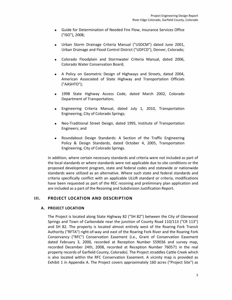
The Project is located along State Highway 82 ("SH 82") between the City of Glenwood Springs and Town of Carbondale near the junction of County Road 110/113 ("CR 113") and SH 82. The property is located almost entirely west of the Roaring Fork Transit Authority ("RFTA") right-of-way and east of the Roaring Fork River and the Roaring Fork Conservancy ("RFC") Conservation Easement (i.e., Grant of Conservation Easement dated February 3, 2000, recorded at Reception Number 559036 and survey map, recorded December 24th, 2008, recorded at Reception Number 760571 in the real property records of Garfield County, Colorado). The Project straddles Cattle Creek which is also located within the RFC Conservation Easement. A vicinity map is provided as Exhibit 1 in Appendix A. The Project covers approximately 160 acres ("Project Site") as

Project Engineering Design Report River Edge Colorado, Garfield County, Colorado
6
shown and described on the Project Site drawing [Exhibit 2(a-d), Appendix A]. The Project is proposed by Carbondale Investments, LLC ("CI").
B. PROJECT DESCRIPTION
The Project is a proposal to create a walkable clustered-form of residential development with neighborhood amenities including naturalized open space and enhanced wildlife habitat, community recreation, parks, and neighborhood agriculture that is designed to serve the residents and preserve and provide reference to the rural character and agricultural roots of the Roaring Fork Valley. The Project aims to have a strong historic identity back to the days of ‘old Colorado’ when compact neighborhoods formed with a strong sense of community based on the land and surrounding landscape. The REC landscape aesthetic will be simple, informal, and place emphasis in the use of plant and landscape materials local, adaptable and appropriate to the climate and environment of the area. The Project will include approximately 366 residential units of various sizes and types including 55 affordable homes and one exclusive executive lot for a custom home. Housing types will range from attached homes to small single family attached and detached garden homes, village homes, and larger estate homes. Smaller garden homes are anticipated to be designed for younger residents that are looking for their first home in the County, while village homes and estate homes will provide move up opportunities for growing families. Densities in the Project are proposed at less than 2½ units per acre. Lot sizes will vary from over 1 acre to approximately 5,000 square feet for single family homes, and 1,700-5000 square feet of lot area for each garden home. Most of the units back to either proposed active parks or reclaimed open space to help enhance the connection to the land. The REC layout and design is depicted in the PUD Plan, PUD01-03 Series and the Preliminary Plan PRPN01-03 Series of the Drawing Package.
The architectural theme will be complementary to the traditional architecture of the valley. Generally, exterior materials will include wood, stone, brick, stucco and cement board siding. Varied roof heights and articulation of the front elevations will be used to break up the massing and provide street-level appeal. Front porches and covered stoops are included on homes to emphasize the entry and connection to the sidewalk and street. Roofing will include dimensional shingles, metal, or other materials appropriate to the building style and that roofs will generally be pitched. Gables, wall plane and roofline articulation, bays, balconies, porches, canopies and arcades will be used in the design of various buildings. The selection of materials will minimize the exterior maintenance of the homes to help maintain a quality appearance for the long term.
The street pattern and pedestrian network are designed to facilitate community interaction. Streets have detached sidewalks with designated cross walks at major intersections and landscaped areas that create a comfortable environment for walking. On‐street parking in most areas will further buffer vehicular and pedestrian uses. Internal circulation is maximized and dead‐end streets are limited. Alleys are used where appropriate to enhance the streetscape and achieve a mix of housing styles. A soft trail system is used to connect open spaces and other common elements with the sidewalk network. The homes are placed close to the streets to help define the

Project Engineering Design Report River Edge Colorado, Garfield County, Colorado
7
streetscape space and provide visual interest to pedestrians. Street trees and plantings are proposed to enhance the aesthetics of the street.
The community is served with a variety of recreational facilities and a neighborhood center that could include meeting room(s), fitness room, offices, kitchen, restrooms, recreational facilities, and limited community service use such as a day care facility, deli/coffee shop, or health club. Parks will provide informal recreational opportunities within the community and will likely include tot lots, playfields, and trail system. The west portion of the property is generally set aside as the naturalized area that buffers the RFC Conservation Easement along the Roaring Fork River. The soft trails around the property allow residents to enjoy the river and wetland areas without disrupting the environment in conformance with the terms of the RFC Conservation Easement. More than the minimum open space requirements will be met by the project. Nearly 50% of the Project Site is in some form of open space, common area or park. Finally, opportunities for productive and edible landscapes, including community gardens and neighborhood orchards are integrated and dispersed in between the residential land uses as gathering and focal places for residents connecting REC to its agricultural heritage.
The combination of trails, recreation areas, and open space system with the ability to engage in ‘interactive community agriculture’ on a small scale will make REC a very desirable place to live, filling a unique niche not yet met in Garfield County. This unique combination will help establish a sense of place, foster community, and engage residents with their immediate environment. It is intended this overall outdoor focus will set the tone and become a major driver of the identity of REC.
IV. DESCRIPTION OF DESIGN AND CONSTRUCTION
1. SITE RECLAMATION (PHASE 0)
Past development efforts that were prematurely terminated left the overall Project Site in poor condition as a result of extensive grading including substantial cut and fill areas and the removal of protective surface soils. Prior to initiating development activities, the Project Site must be reclaimed in order to address a variety of issues resulting from the degradation and land form changes associated with such previous activities. The Reclamation Plan (Appendix U of the Impact Report) details the proposed pre-development reclamation activates proposed for the Project Site that would be under taken as Phase 0 in advance of development construction. These activities are shown on the Series RP01 of the Drawing Package and the post-reclamation conditions are shown on the Series ES02 of the Drawing Package. Where development-related actions are most appropriately taken at the time of reclamation and would result in limiting site disturbance and habitat impacts or alleviating safety issues and concerns, these actions are included in the proposed reclamation actions.
Although site reclamation is proposed as a pre-development action, the development plans and drawings are based on existing conditions and not on

Project Engineering Design Report River Edge Colorado, Garfield County, Colorado
8
post-reclamation conditions. Final design must be coordinated with the post-reclamation conditions once these actions are completed.
2. ROADS
Roads internal to the site were planned as continuous streets to provide for vehicular movement and facilitate mobility for other modes of travel with attached sidewalks and bike friendly speeds and sections. The residential areas are "clustered" with urban densities. Therefore, the standards used for street design were built based on the standards and framework provided by existing Garfield County road design standards contained in Section 7-307 of the ULUR, but were modified to meet Project objectives utilizing urban road design standards from several municipal jurisdictions in Colorado (i.e., most specially the City of Colorado Springs but also included a review of design standards in the City of Fort Collins and City of Denver), AASHTO and Neo-Traditional Street Design. The street sections adopted for use at REC are on shown on Typical Street and Trail Sections, C04 Series of the Drawing Package. The design criteria used for street layouts (Street Plan and Profiles, C02 Series of the Drawing Package) are as presented in Table 1. The criteria are well within other jurisdictional standards for comparable development plans and meet the needs of the Carbondale Fire Protection District. In addition to vehicular movement, all the streets provide for on-street parking and detached sidewalks except alleys and courts.
Table 1: Street Design Criteria
Criteria
Entry Road
Local
Alley /
Court
Garden Home Access
Emergency Vehicle Access
(EVA)
Design Capacity (ADT) 8,000 5,000 <500 <500 n/a
Design Speed (mph) 25 25 n/a n/a n/a
Posted Speed (mph) 25 25 n/a n/a n/a
Pavement Width (Lanes) 24 (2)1 36 (2)
2 24 (2)
3 20 (2)
4 20
Min. Horizontal Radius (ft) 185 80 50 50 n/a
Design Vehicle WB-50 WB-40 n/a n/a n/a
Curb Return Radii (ft) 30 20 n/a n/a n/a
Max. Grade (%) 8 8 8 8 8
Cross Slope (%) 2 2 2 n/a n/a
Surface Asphalt Asphalt Asphalt Asphalt Asphalt 1 Two 12' travel lanes plus raised median (varying width) and no on-street parking.
2 Two 10' travel lanes and on-street parking on both sides of the street.
3 Two 10' travel lanes and 2' shoulders.
4 Two 10' travel lanes.
The street hierarchy for the planned development consists primarily of two sections, Local and Alleys/Courts. Local streets provide site-wide mobility for homeowners and guests at a capacity that will exceed 5,000 vpd. The Local road

Project Engineering Design Report River Edge Colorado, Garfield County, Colorado
9
section also allows for on-street parking on both sides of the street throughout all neighborhoods and direct access to all front loaded residential lots (driveway spacing is approximately 50 feet). Drainage will be controlled through the use of curb and gutters which direct flows toward storm sewer inlets. The Local street section was selected based on the planned character of the neighborhoods and level of safety expected for those using the street or interacting with it from the adjoining lots. Examples of similar urban streets can be found in Eagle Ranch, Town of Eagle, Eagle County, Colorado. Alleys/ Courts provide short connections between Local streets and access to rear loaded residential lots and garden homes (driveway spacing of less than 40 feet). The required minimum width of pavement for the Alleys/Courts sections is 20 feet per discussions with the Carbondale Fire Protection District. The Alleys/Courts section provides for 24 feet of pavement, Drainage will be controlled through the use of cross pans which direct flows toward the adjoining Local streets or adjacent drainageways. All lots directly access private streets that then access SH 82 via the main entrance at Cattle Creek Road.
In addition to these two primary street sections, the entry road (River Edge Drive) is the approximately 500 foot street segment from the main access off SH 82 to the roundabout. The street section associated with this segment of road is adjusted throughout its length so as to coordinate with the highway access, RFTA right-of-way crossing, entrance to the neighborhood center and proper entry the roundabout.
Detailed coordination on the entry road with CDOT and RFTA will be necessary during the final design process to ensure the design requirements of each agency are met Based on discussions with CDOT, it is anticipated that CDOT review will be threefold in accordance with the State Access Code. First, CI was required to complete a traffic assessment per requirements of Garfield County. Second, CI will be required to develop near and long term concepts to be used in discussions with affected agencies and land owners. Third, CI will be required to prepare a Level III Traffic Impact Report and final intersection design to support application for a CDOT Access Permit. In addition to the main access, two Emergency Vehicle Access (EVA) points have been discussed with CDOT, RFTA, and Carbondale Fire Protection District. The EVAs will be access-controlled to only allow for access during an emergency, no other access at these locations will be permitted.
A roundabout is proposed at the main intersection internal to the development as a means of best accommodating traffic from the northern and southern areas of the Project. The roundabout is designed in accordance with standards from the City of Colorado Springs. The capacity for the roundabout will exceed 20,000 vehicles per day (vpd), with a peak hour capacity of 1,500. The preliminary design is provided on Roundabout Layout, C03 Series of the Drawing Package.
The preliminary design associated with road network is presented on the supporting drawings (Series C01 - C07 of the Drawing Package),
Project Engineering Design Report River Edge Colorado, Garfield County, Colorado
10
3. WATER AND WASTEWATER
Onsite water and wastewater utilities are designed to support the planned development while considering future growth within the area outside Project. The overall layout of utilities generally mirrors the horizontal alignments of the streets. However, where appropriate the utility network was placed in easements outside paved street sections to create a more efficient and cost effective system.
The RFWSD Rules and Regulations dated February 2007 were utilized as the primary source for design standards and criteria. The primary objective of the preliminary design was to consider the RFWSD standards in relationship to the site conditions and the planned development. In a vast majority of the situations the RFWSD standards can be met. However, there may be limited instances where the density of the "clustered" development may result in the need to vary from the RFWSD standards to achieve the design objectives. In these instances, the alternative standards will be coordinated with RFWSD to ensure the primary objectives for the water and wastewater systems are met.
Based on the preliminary design, the only RFWSD standard not currently met was the minimum depth of flow within the sanitary sewer lines (i.e., 50 percent at peak flows). The minimum sanitary sewer line flow depth standard utilized by the RFWSD is somewhat unusual. The typical standard for depth of flow in pipes is focused on a maximum flow depth targeted at making sure the pipe is not pushed beyond its capacity when reaching peak flows. Therefore, the standard would typically be written as a maximum 50-percent full during average flows and a maximum 80-percent full during peak flows. Under the proposed standards, the system as planned will achieve the alternative standard of flow depth at the slopes, velocities, and pipe sizes presented.
The preliminary design associated with water supply, treatment and distributions and sewage collection and disposal are described in detail in the Sewage Collection Report, Water Treatment and Distribution Design Report, Water Supply Plan and Sanitary Sewage Disposal Plan and supporting drawings (Series SW01 - SW04 of the Drawing Package).
In addition to the planned water and sewage systems described above, the Project will provide raw water irrigation. The raw water will come from the Glenwood Ditch and be piped across the site via a community-owned and operated distribution system. This system is required under the water rights adjudications which will provide potable water. The Raw Water Supply and Distribution Plan and supporting drawings (Series SW05 of the Drawing Package) detail the preliminary design of the raw water system.
4. DRY UTILITIES
Dry utility service provided by regional providers was also considered during the development of the preliminary design. Accessible and coordinated corridors for installation of these services have been planned for in the design and each

Project Engineering Design Report River Edge Colorado, Garfield County, Colorado
11
provider has provided a "will serve" letter (Appendix B). Easements are provided along lot lines. Utilities are also accommodated in Right-of-Way Tracts
5. EROSION AND SEDIMENT CONTROL
Under the Garfield County ULUR, the Erosion and Sediment Control Plan ("ESCP") is an all encompassing plan supporting grading, drainage, and surface water quality requirements. As such, the ESCP documents existing, reclaimed, phased and final conditions of the Project. In addition, the ESCP supports other plans such as the Reclamation Plan and the Hazard Mitigation Plan by defining how surface water is managed throughout the entire development process.
As presented in the ESCP, the surface water quality and quantity is managed two ways utilizing the criteria from the USDCM. First, the runoff created by the development is limited by the design (i.e. reduced areas of imperviousness) and conveyed directly offsite to either Cattle Creek or the Roaring Fork River. Second, the "first flush" of surface water, which typically contains the highest concentration of contaminants, is treated via vegetated channels or through capture in one of three "water quality" ponds. No detention of storm water quantity volumes is proposed. The direct release of runoff from the Project Site without detention is discussed in detail in the ESCP. However, the two primary reasons behind this requested modification are that: (1) the site is low in the basin therefore releasing the runoff from the Project Site prior to the peak flows from other contributing basins upstream likely better limits the magnitude of the peak runoff condition downstream of the Project Site; (2) the direct release has no affect on any downstream properties or existing stormwater facilities.
The preliminary design associated with the Erosion and Sediment Control Plan are detailed in the related report and supporting drawings (Series ES01 - ES05 of the Drawing Package).
6. DRAINAGE STRUCTURES
Culverts and storm sewer were preliminarily located and culverts sized for the entire Project Site based on the overall drainage needs and design intent.
The goal for stormwater management for the Project is to minimize storm water conveyance via piping and utilize open space areas to collect and convey storm water. Therefore, inlets located in road will immediately discharge to swales located in adjacent open space on much of the site. This approach provides two benefits. Discharging to grass swales will provide enhanced water quality prior to discharge to receiving waters (i.e. Cattle Creek and Roaring Fork River), and utilization of grass swales will provide increased travel time relative to conveyance via storm sewer pipe which servers to decrease peak flows and potentially reduces the size of major conveyance features. However there are three locations where it is anticipated that storm sewer will be needed due to the Project design constraints.

Project Engineering Design Report River Edge Colorado, Garfield County, Colorado
12
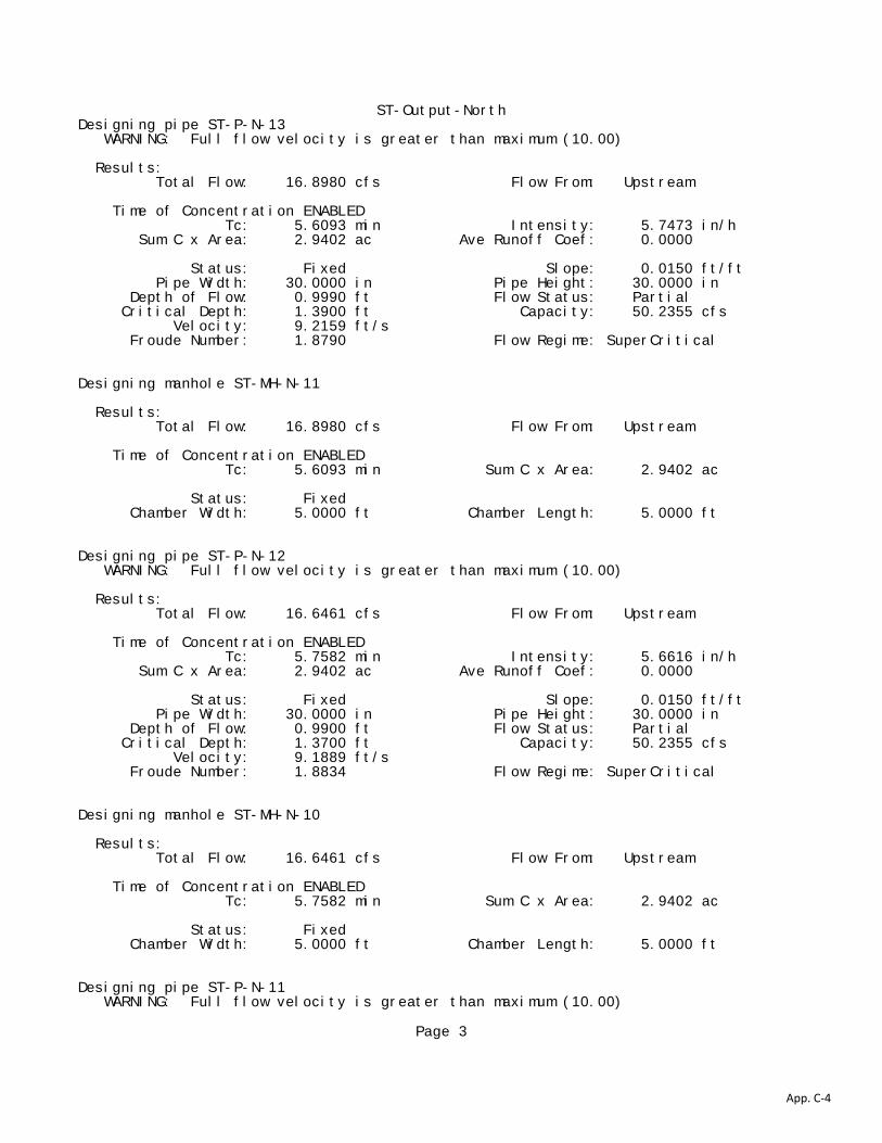
For preliminary analysis, storm sewers were sized and designed in three locations. There is one storm sewer system on the north portion of the Project and two on the south. The northern system captures the main drainage channel that drains much of the north portion of the project (Basin P2) as well as the offsite basin to the east (Basin OS-1) and discharges to Pond NP2. Therefore, a more detailed preliminary analysis was conducted on this system to ensure the system could accommodate the anticipated flows. A conservative 100-year return period storm was used and the results of this analysis are shown in Appendix C. A more basic analysis was conducted for the other two systems as these are minor in nature. The Riverside Loop Drive system has a capacity of 100 cfs and an anticipated 100-year flow of 12 cfs. The Alpine Bluff Street system has a capacity of 100 cfs and an anticipated 100-year flow of 20 cfs. A preliminary layout of all these systems can be found in Series DR01-03 of the Drawing Package.
Preliminary calculations for culvert sizing were also completed along all drainage channels and can be found in Appendix C. Preliminary sizing of the culverts was done in accordance with the USDCM methodology. The stage-discharge relationship and entrance and exit head loss given the configuration of the culvert are provided. For each stage, a maximum flow rate for both inlet control and outlet control is calculated. A manning’s “n” of 0.013 was used for all culverts. Slopes were estimated based on the current over-lot grading plan and minimum cover was assumed to be 18-inches when underneath a road. Material for all culverts is preliminarily proposed as concrete and pipe class will be determined at final design based on estimated loading. Proposed culvert locations are shown on the Drainage Structures Plan and Profiles, DR02 Series of the Drawing Package.

Project Engineering Design Report River Edge Colorado, Garfield County, Colorado
APPENDIX A: VICINITY MAP AND PROJECT SITE DRAWINGS
App. B-1

12/01/10VICINITY MAP
Exhibit:
Date:
8140 Partners, LLC
Title:
Prepared by:
Owner/Developer:
Carbondale Investments, LLC7999 HWY 82Carbondale, CO 81623
Phone No:970.456.5325
App. B-2
msawyer
Typewritten Text
1
msawyer
Typewritten Text
1
msawyer
Typewritten Text
msawyer
Typewritten Text
msawyer
Rectangle
msawyer
Typewritten Text
PROJECT SITE

Exhibit:
Date:
8140 Partners, LLC
Title:
Prepared by:
Owner/Developer:
Carbondale Investments, LLC7999 HWY 82Carbondale, CO 81623
Phone No:970.456.5325
12/01/10
App. B-3
msawyer
Typewritten Text
2(a)
msawyer
Typewritten Text
msawyer
Typewritten Text
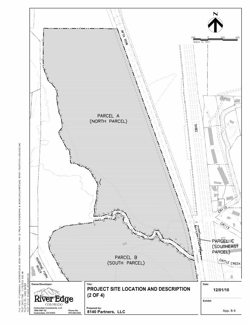
Exhibit:
Date:
8140 Partners, LLC
Title:
Prepared by:
Owner/Developer:
Carbondale Investments, LLC7999 HWY 82Carbondale, CO 81623
Phone No:970.456.5325
12/01/10
App. B-4
msawyer
Typewritten Text
2(b)

Exhibit:
Date:
8140 Partners, LLC
Title:
Prepared by:
Owner/Developer:
Carbondale Investments, LLC7999 HWY 82Carbondale, CO 81623
Phone No:970.456.5325
12/01/10
App. B-5
msawyer
Typewritten Text
2(c)

Exhibit:
Date:
8140 Partners, LLC
Title:
Prepared by:
Owner/Developer:
Carbondale Investments, LLC7999 HWY 82Carbondale, CO 81623
Phone No:970.456.5325
12/01/10
App. B-6
msawyer
Typewritten Text
2(d)

Project Engineering Design Report River Edge Colorado, Garfield County, Colorado
APPENDIX B: WILL SERVE LETTERS
App. B-1
App. B-2

"basS"""--I
May 26, 2010
From', Carla Westcm1an SourceGas 0096 County Rd. 160 Glenwood Springs, CO 81601 970-928-0407
To: Rockwood Shepard. Carbondale Investments, LLC C/O 8140 Partners. LLC PO Box 426 Eagle, CO 81631
RE: Carbondale Investments. LLe Project
To whom it may concern:
The above mentioned development is wilhin the ccrti rlcated service area of SourceGas. have received your vicinity map, and master plan for this project.
SourceGas has existing natural gas facilities located on or near the above mentioned project. At this time il appears that these existing facilities have adequate capacity to provide natural gas service to your project, subject to the tariffs, rules and regulations on file, Any upgrading of alII facilities necessary to deliver adequate service 10 and within the development ".... ill be undertaken by Source(ias upon completion of appropriate contractual agreements and subject to necessary governmental approvals.
Please cOnlact us with any questions regarding this project, and witb a timeline of when you would l.ike to proceed with your project
/
S· I I" ulcere f'
f / I
(cu,f\vestennan~Id Coordinator
App. B-3

App. B-4

App. B-5

App. B-6

App. B-7

App. B-8

App. B-9
App. B-10

App. B-11

App. B-12

App. B-13

... ell- OSS - [:
v o
:<: ;,799 HIGHWAY 82 • PO BOX 2150
GLENWOOD SPRfNGS, COLORADO 81602 -r Ll
(970)945-5491 . FAX (9701 945-4081
<$-_, )I )
"'1\1 ;;
- ')SSO\\
May 25, 2010
8140 Partners, LLC Ann: Karen Otero PO Box 426 Eagle. CO 81631-0426
RE: Carbondale Investments, LLC Project
To Whom it May Concern:
The above mentioned development is within the certificated service area of Holy Cross Energy.
Holy Cross Energy has existing power facilities located on or near the above mentioned project. Thes e ex is ti ng facil iti es have adequate capacity to provide electric power to the deve lopment, subject to the tariffs. rules and regulations on file. Any power line enlargements, relocations, and new extensions necessary to deliver adequate power to and within the development will be undertaken by Holy Cross Energy upon completion of appropriate contractual agreemems and subject to necessary governmental approvals.
Please advise when you wish to proceed with the development of the electric system for this project.
Sincerely, HOLY CROSS ENERGY
~'.~,-(~
Kenton Berner, Engineering Department
[email protected] (970) 947-5497
K8:vw
Berner\Olero
A T,'lKh,tnrw Ener\!\ C,w'l'oCr,lll\'\' ~ App. B-14

Project Engineering Design Report River Edge Colorado, Garfield County, Colorado
APPENDIX C: STORM SEWER, INLET AND CULVERT SIZING
App. C-1

ST-Output-North Design Log =====================================================================InRoads Storm & Sanitary Design Log
Drainage File: P:\Carbondale Investments\06.00 Design Tasks\06.02 - Task 02 Prelim Plat\Engineering & Design\Calculations\InRoads\SDB\REC - Drain.sdb
Design File: C:\DOCUMENTS AND SETTINGS\JADAMS\MY DOCUMENTS\8140\CCX 2010\REC REV PLAN 9-2-10 WORKING\DRAINAGE WORKING 11-10-10.DWG
Display Log: C:\DOCUMENTS AND SETTINGS\JADAMS\MY DOCUMENTS\8140\CCX 2010\REC REV PLAN 9-2-10 WORKING\design.log
Date: Monday, November 29, 2010 11:57:42 AM======================================================================
Designing inlet IN-MOD-ONLY-4 WARNING: Spread is greater than maximum spread (2.50 ft ) Results: Gutter Flow: 17.1119 cfs Flow From: Area Time of Concentration ENABLED Tc: 5.0000 min Intensity: 5.8200 in/h Sum C x Area: 2.9402 ac Ave Runoff Coef: 0.3800 Status: Fixed Inlet Length: 6.0000 ft Inlet Width: 2.0000 ft Flow Downstream: 17.1119 cfs Percent Cap: 100.0000 % Capacity: 17.1125 cfs Spread: 10.2984 ft Depth in Gutter: 0.1878 ft Assigned Bypass: N/A Designing pipe P-MOD-ONLY-5 WARNING: Full flow velocity is greater than maximum (10.00) Results: Total Flow: 17.1119 cfs Flow From: Upstream Time of Concentration ENABLED Tc: 5.0189 min Intensity: 5.8200 in/h Sum C x Area: 2.9402 ac Ave Runoff Coef: 0.0000 Status: Fixed Slope: 0.0500 ft/ft Pipe Width: 30.0000 in Pipe Height: 30.0000 in Depth of Flow: 0.7310 ft Flow Status: Partial Critical Depth: 1.3900 ft Capacity: 91.7171 cfs Velocity: 14.2902 ft/s Froude Number: 3.4753 Flow Regime: SuperCritical Designing manhole ST-MH-N-14 Results: Total Flow: 17.1119 cfs Flow From: Upstream Time of Concentration ENABLED Tc: 5.0189 min Sum C x Area: 2.9402 ac Status: Fixed
Page 1
App. C-2

ST-Output-North Chamber Width: 5.0000 ft Chamber Length: 5.0000 ft Designing pipe ST-P-N-15 WARNING: Full flow velocity is greater than maximum (10.00) Results: Total Flow: 17.0974 cfs Flow From: Upstream Time of Concentration ENABLED Tc: 5.0689 min Intensity: 5.8151 in/h Sum C x Area: 2.9402 ac Ave Runoff Coef: 0.0000 Status: Fixed Slope: 0.0200 ft/ft Pipe Width: 30.0000 in Pipe Height: 30.0000 in Depth of Flow: 0.9290 ft Flow Status: Partial Critical Depth: 1.3900 ft Capacity: 58.0070 cfs Velocity: 10.2799 ft/s Froude Number: 2.1860 Flow Regime: SuperCritical Designing manhole ST-MH-N-13 Results: Total Flow: 17.0974 cfs Flow From: Upstream Time of Concentration ENABLED Tc: 5.0689 min Sum C x Area: 2.9402 ac Status: Fixed Chamber Width: 5.0000 ft Chamber Length: 5.0000 ft Designing pipe ST-P-N-14 WARNING: Full flow velocity is greater than maximum (10.00) Results: Total Flow: 17.0592 cfs Flow From: Upstream Time of Concentration ENABLED Tc: 5.2798 min Intensity: 5.8021 in/h Sum C x Area: 2.9402 ac Ave Runoff Coef: 0.0000 Status: Fixed Slope: 0.0150 ft/ft Pipe Width: 30.0000 in Pipe Height: 30.0000 in Depth of Flow: 1.0040 ft Flow Status: Partial Critical Depth: 1.3900 ft Capacity: 50.2355 cfs Velocity: 9.2421 ft/s Froude Number: 1.8789 Flow Regime: SuperCritical Designing manhole ST-MH-N-12 Results: Total Flow: 17.0592 cfs Flow From: Upstream Time of Concentration ENABLED Tc: 5.2798 min Sum C x Area: 2.9402 ac Status: Fixed Chamber Width: 5.0000 ft Chamber Length: 5.0000 ft
Page 2
App. C-3
ST-Output-NorthDesigning pipe ST-P-N-13 WARNING: Full flow velocity is greater than maximum (10.00) Results: Total Flow: 16.8980 cfs Flow From: Upstream Time of Concentration ENABLED Tc: 5.6093 min Intensity: 5.7473 in/h Sum C x Area: 2.9402 ac Ave Runoff Coef: 0.0000 Status: Fixed Slope: 0.0150 ft/ft Pipe Width: 30.0000 in Pipe Height: 30.0000 in Depth of Flow: 0.9990 ft Flow Status: Partial Critical Depth: 1.3900 ft Capacity: 50.2355 cfs Velocity: 9.2159 ft/s Froude Number: 1.8790 Flow Regime: SuperCritical Designing manhole ST-MH-N-11 Results: Total Flow: 16.8980 cfs Flow From: Upstream Time of Concentration ENABLED Tc: 5.6093 min Sum C x Area: 2.9402 ac Status: Fixed Chamber Width: 5.0000 ft Chamber Length: 5.0000 ft Designing pipe ST-P-N-12 WARNING: Full flow velocity is greater than maximum (10.00) Results: Total Flow: 16.6461 cfs Flow From: Upstream Time of Concentration ENABLED Tc: 5.7582 min Intensity: 5.6616 in/h Sum C x Area: 2.9402 ac Ave Runoff Coef: 0.0000 Status: Fixed Slope: 0.0150 ft/ft Pipe Width: 30.0000 in Pipe Height: 30.0000 in Depth of Flow: 0.9900 ft Flow Status: Partial Critical Depth: 1.3700 ft Capacity: 50.2355 cfs Velocity: 9.1889 ft/s Froude Number: 1.8834 Flow Regime: SuperCritical Designing manhole ST-MH-N-10 Results: Total Flow: 16.6461 cfs Flow From: Upstream Time of Concentration ENABLED Tc: 5.7582 min Sum C x Area: 2.9402 ac Status: Fixed Chamber Width: 5.0000 ft Chamber Length: 5.0000 ft Designing pipe ST-P-N-11 WARNING: Full flow velocity is greater than maximum (10.00)
Page 3
App. C-4

ST-Output-North Results: Total Flow: 16.5322 cfs Flow From: Upstream Time of Concentration ENABLED Tc: 5.9151 min Intensity: 5.6229 in/h Sum C x Area: 2.9402 ac Ave Runoff Coef: 0.0000 Status: Fixed Slope: 0.0150 ft/ft Pipe Width: 30.0000 in Pipe Height: 30.0000 in Depth of Flow: 0.9870 ft Flow Status: Partial Critical Depth: 1.3700 ft Capacity: 50.2355 cfs Velocity: 9.1632 ft/s Froude Number: 1.8815 Flow Regime: SuperCritical Designing manhole ST-MH-N-9 Results: Total Flow: 16.5322 cfs Flow From: Upstream Time of Concentration ENABLED Tc: 5.9151 min Sum C x Area: 2.9402 ac Status: Fixed Chamber Width: 5.0000 ft Chamber Length: 5.0000 ft Designing pipe ST-P-N-10 WARNING: Full flow velocity is greater than maximum (10.00) Results: Total Flow: 16.4124 cfs Flow From: Upstream Time of Concentration ENABLED Tc: 6.0553 min Intensity: 5.5821 in/h Sum C x Area: 2.9402 ac Ave Runoff Coef: 0.0000 Status: Fixed Slope: 0.0150 ft/ft Pipe Width: 30.0000 in Pipe Height: 30.0000 in Depth of Flow: 0.9830 ft Flow Status: Partial Critical Depth: 1.3600 ft Capacity: 50.2355 cfs Velocity: 9.1463 ft/s Froude Number: 1.8825 Flow Regime: SuperCritical Designing inlet MOD-ONLY-1 Results: Gutter Flow: 5.5368 cfs Flow From: Area Time of Concentration ENABLED Tc: 5.0000 min Intensity: 5.8200 in/h Sum C x Area: 0.9513 ac Ave Runoff Coef: 0.4200 Status: Fixed Inlet Length: 6.0000 ft Inlet Width: 2.0000 ft Flow Downstream: 5.5368 cfs Percent Cap: 100.0000 % Capacity: 10.6098 cfs Spread: 0.0079 ft Depth in Gutter: 0.0001 ft Assigned Bypass: N/A Designing pipe P-MOD-ONLY-2
Page 4
App. C-5

ST-Output-North Results: Total Flow: 5.5368 cfs Flow From: Upstream Time of Concentration ENABLED Tc: 5.0602 min Intensity: 5.8200 in/h Sum C x Area: 0.9513 ac Ave Runoff Coef: 0.0000 Status: Fixed Slope: 0.0097 ft/ft Pipe Width: 30.0000 in Pipe Height: 30.0000 in Depth of Flow: 0.6240 ft Flow Status: Partial Critical Depth: 0.7700 ft Capacity: 40.4694 cfs Velocity: 5.7695 ft/s Froude Number: 1.5291 Flow Regime: SuperCritical Designing manhole ST-MH-N-8 Results: Total Flow: 21.5809 cfs Flow From: Upstream Time of Concentration ENABLED Tc: 6.0553 min Sum C x Area: 3.8915 ac Status: Fixed Chamber Width: 5.0000 ft Chamber Length: 5.0000 ft Designing pipe ST-P-N-9 WARNING: Full flow velocity is greater than maximum (10.00) Results: Total Flow: 21.5809 cfs Flow From: Upstream Time of Concentration ENABLED Tc: 6.3914 min Intensity: 5.5456 in/h Sum C x Area: 3.8915 ac Ave Runoff Coef: 0.0000 Status: Fixed Slope: 0.0150 ft/ft Pipe Width: 30.0000 in Pipe Height: 30.0000 in Depth of Flow: 1.1440 ft Flow Status: Partial Critical Depth: 1.5700 ft Capacity: 50.2355 cfs Velocity: 9.8445 ft/s Froude Number: 1.8511 Flow Regime: SuperCritical Designing manhole ST-MH-N-7 Results: Total Flow: 21.5809 cfs Flow From: Upstream Time of Concentration ENABLED Tc: 6.3914 min Sum C x Area: 3.8915 ac Status: Fixed Chamber Width: 5.0000 ft Chamber Length: 5.0000 ft Designing pipe ST-P-N-8 Results: Total Flow: 21.2408 cfs Flow From: Upstream
Page 5
App. C-6

ST-Output-North Time of Concentration ENABLED Tc: 6.6685 min Intensity: 5.4582 in/h Sum C x Area: 3.8915 ac Ave Runoff Coef: 0.0000 Status: Fixed Slope: 0.0072 ft/ft Pipe Width: 30.0000 in Pipe Height: 30.0000 in Depth of Flow: 1.4100 ft Flow Status: Partial Critical Depth: 1.5600 ft Capacity: 34.8196 cfs Velocity: 7.4379 ft/s Froude Number: 1.2224 Flow Regime: SuperCritical Designing manhole ST-MH-N-6 Results: Total Flow: 21.2408 cfs Flow From: Upstream Time of Concentration ENABLED Tc: 6.6685 min Sum C x Area: 3.8915 ac Status: Fixed Chamber Width: 5.0000 ft Chamber Length: 5.0000 ft Designing pipe ST-P-N-7 Results: Total Flow: 20.9605 cfs Flow From: Upstream Time of Concentration ENABLED Tc: 6.8019 min Intensity: 5.3862 in/h Sum C x Area: 3.8915 ac Ave Runoff Coef: 0.0000 Status: Fixed Slope: 0.0050 ft/ft Pipe Width: 30.0000 in Pipe Height: 30.0000 in Depth of Flow: 1.5740 ft Flow Status: Partial Critical Depth: 1.5500 ft Capacity: 29.0035 cfs Velocity: 6.4343 ft/s Froude Number: 0.9770 Flow Regime: Critical Designing manhole ST-MH-N-5 Results: Total Flow: 20.9605 cfs Flow From: Upstream Time of Concentration ENABLED Tc: 6.8019 min Sum C x Area: 3.8915 ac Status: Fixed Chamber Width: 5.0000 ft Chamber Length: 5.0000 ft Designing pipe ST-P-N-6 Results: Total Flow: 20.8255 cfs Flow From: Upstream Time of Concentration ENABLED Tc: 7.0626 min Intensity: 5.3515 in/h Sum C x Area: 3.8915 ac Ave Runoff Coef: 0.0000 Status: Fixed Slope: 0.0050 ft/ft
Page 6
App. C-7

ST-Output-North Pipe Width: 30.0000 in Pipe Height: 30.0000 in Depth of Flow: 1.5670 ft Flow Status: Partial Critical Depth: 1.5500 ft Capacity: 29.0035 cfs Velocity: 6.4262 ft/s Froude Number: 0.9790 Flow Regime: Critical Designing channel CH-N-1 Results: Total Flow: 80.1713 cfs Flow From: Area Time of Concentration ENABLED Tc: 26.8736 min Intensity: 3.0716 in/h Sum C x Area: 26.1008 ac Ave Runoff Coef: 0.4463 Status: Fixed Slope: 0.0053 ft/ft Left Side Slope: 1.0000 ft/ft Right Side Slope: 1.0000 ft/ft Maximum Depth: 4.0000 ft Channel Bottom: 3.0000 ft Depth of Flow: 2.8828 ft Top Width: 8.7656 ft Critical Depth: 2.1920 ft Velocity: 4.7273 ft/s Designing culvert CV-N-1 Results: Total Flow: 75.4013 cfs Flow From: Upstream Time of Concentration ENABLED Tc: 27.0452 min Intensity: 2.8888 in/h Sum C x Area: 26.1008 ac Ave Runoff Coef: 0.0000 Control: Outlet Inlet Control Eqn: Entrance Loss Status: Fixed Slope: 0.0115 ft/ft Culvert Width: 48.0000 in Culvert Height: 48.0000 in Critical Depth: 1.8300 ft Num Barrels: 2 Headwater: 3.1973 ft Tailwater: 3.3600 ft Velocity: 3.3456 ft/s WARNING: Culvert too large for upstream channelDesigning channel CH-N-2 Results: Total Flow: 75.0760 cfs Flow From: Upstream Time of Concentration ENABLED Tc: 29.1802 min Intensity: 2.8764 in/h Sum C x Area: 26.1008 ac Ave Runoff Coef: 0.0000 Status: Fixed Slope: 0.0059 ft/ft Left Side Slope: 1.0000 ft/ft Right Side Slope: 1.0000 ft/ft Maximum Depth: 4.0000 ft Channel Bottom: 3.0000 ft Depth of Flow: 2.6953 ft Top Width: 8.3906 ft Critical Depth: 2.1150 ft Velocity: 4.8907 ft/s WARNING: Channel too small for upstream culvert.Designing pipe ST-P-N-5 Results:
Page 7
App. C-8

ST-Output-North Total Flow: 70.6180 cfs Flow From: Upstream Time of Concentration ENABLED Tc: 29.8390 min Intensity: 2.7056 in/h Sum C x Area: 26.1008 ac Ave Runoff Coef: 0.0000 Status: Fixed Slope: 0.0030 ft/ft Pipe Width: 48.0000 in Pipe Height: 48.0000 in Depth of Flow: 2.9590 ft Flow Status: Partial Critical Depth: 2.5400 ft Capacity: 78.6767 cfs Velocity: 7.0829 ft/s Froude Number: 0.7411 Flow Regime: Subcritical Designing manhole ST-MH-N-4 Results: Total Flow: 70.6180 cfs Flow From: Upstream Time of Concentration ENABLED Tc: 29.8390 min Sum C x Area: 26.1008 ac Status: Fixed Chamber Width: 5.0000 ft Chamber Length: 5.0000 ft Designing pipe ST-P-N-4 Results: Total Flow: 69.2423 cfs Flow From: Upstream Time of Concentration ENABLED Tc: 30.5300 min Intensity: 2.6529 in/h Sum C x Area: 26.1008 ac Ave Runoff Coef: 0.0000 Status: Fixed Slope: 0.0030 ft/ft Pipe Width: 48.0000 in Pipe Height: 48.0000 in Depth of Flow: 2.9120 ft Flow Status: Partial Critical Depth: 2.5100 ft Capacity: 78.6767 cfs Velocity: 7.0626 ft/s Froude Number: 0.7504 Flow Regime: Subcritical Designing manhole ST-MH-N-3 Results: Total Flow: 78.7030 cfs Flow From: Upstream Time of Concentration ENABLED Tc: 30.5300 min Sum C x Area: 29.9924 ac Status: Fixed Chamber Width: 5.0000 ft Chamber Length: 5.0000 ft Designing pipe ST-P-N-3 Results: Total Flow: 78.7030 cfs Flow From: Upstream Time of Concentration ENABLED Tc: 30.7472 min Intensity: 2.6241 in/h Sum C x Area: 29.9924 ac Ave Runoff Coef: 0.0000
Page 8
App. C-9
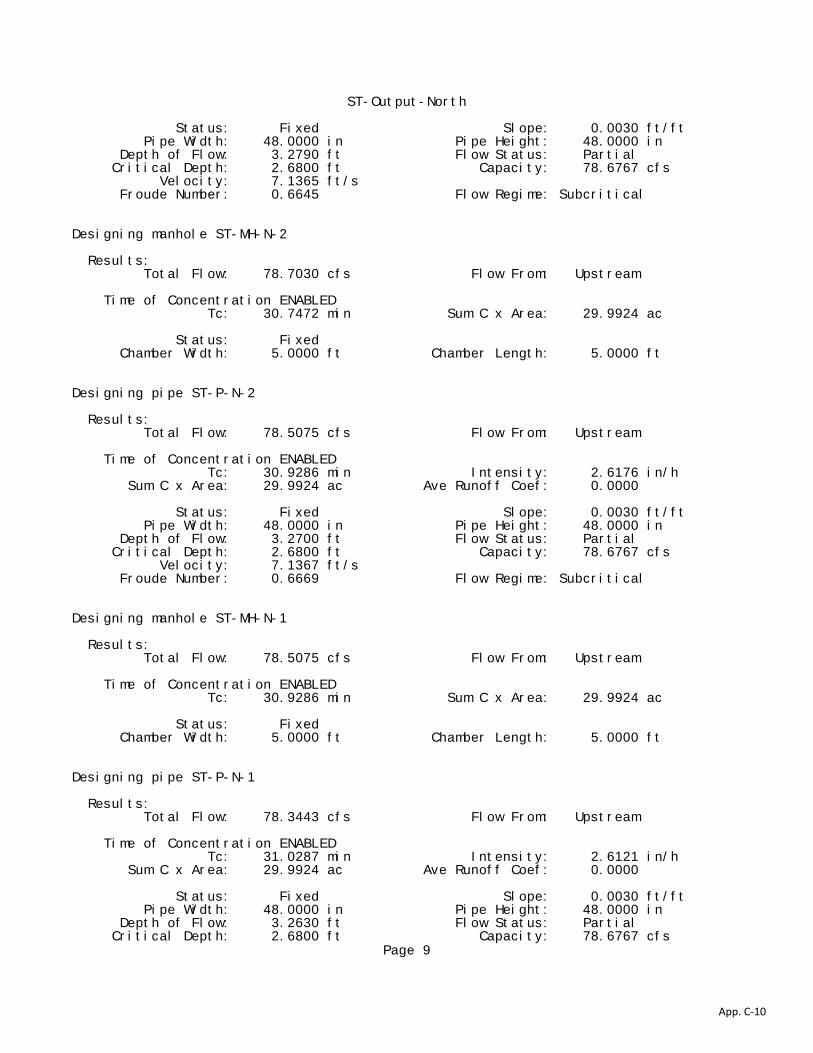
ST-Output-North Status: Fixed Slope: 0.0030 ft/ft Pipe Width: 48.0000 in Pipe Height: 48.0000 in Depth of Flow: 3.2790 ft Flow Status: Partial Critical Depth: 2.6800 ft Capacity: 78.6767 cfs Velocity: 7.1365 ft/s Froude Number: 0.6645 Flow Regime: Subcritical Designing manhole ST-MH-N-2 Results: Total Flow: 78.7030 cfs Flow From: Upstream Time of Concentration ENABLED Tc: 30.7472 min Sum C x Area: 29.9924 ac Status: Fixed Chamber Width: 5.0000 ft Chamber Length: 5.0000 ft Designing pipe ST-P-N-2 Results: Total Flow: 78.5075 cfs Flow From: Upstream Time of Concentration ENABLED Tc: 30.9286 min Intensity: 2.6176 in/h Sum C x Area: 29.9924 ac Ave Runoff Coef: 0.0000 Status: Fixed Slope: 0.0030 ft/ft Pipe Width: 48.0000 in Pipe Height: 48.0000 in Depth of Flow: 3.2700 ft Flow Status: Partial Critical Depth: 2.6800 ft Capacity: 78.6767 cfs Velocity: 7.1367 ft/s Froude Number: 0.6669 Flow Regime: Subcritical Designing manhole ST-MH-N-1 Results: Total Flow: 78.5075 cfs Flow From: Upstream Time of Concentration ENABLED Tc: 30.9286 min Sum C x Area: 29.9924 ac Status: Fixed Chamber Width: 5.0000 ft Chamber Length: 5.0000 ft Designing pipe ST-P-N-1 Results: Total Flow: 78.3443 cfs Flow From: Upstream Time of Concentration ENABLED Tc: 31.0287 min Intensity: 2.6121 in/h Sum C x Area: 29.9924 ac Ave Runoff Coef: 0.0000 Status: Fixed Slope: 0.0030 ft/ft Pipe Width: 48.0000 in Pipe Height: 48.0000 in Depth of Flow: 3.2630 ft Flow Status: Partial Critical Depth: 2.6800 ft Capacity: 78.6767 cfs
Page 9
App. C-10

ST-Output-North Velocity: 7.1359 ft/s Froude Number: 0.6688 Flow Regime: Subcritical
HGL/EGL Computations:
Table A:
Struct_ID D Q L V d dc V^2/2g Sf Dn_Soffit EGLdn HGLdn Tot_Loss EGLup HGLup Rim_Elev. (in) (cfs) (ft) (ft/s) (ft) (ft) (ft) (ft/ft) (ft) (ft) (ft) (ft) (ft) (ft) (ft)
Outfall - - - - - - - - - - - - - 6005.25 - (Alternate HGL and EGL Used) 6006.12 6005.33 ST-P-N-1 48 78.34 42.85 7.14 3.26 2.68 0.79 0.0030 6005.99 6006.12 6005.33 0.13 6006.25 6005.46 - ST-MH-N-1 - - - - - - - - - 6006.25 6005.46 0.20 6006.45 6005.66 6006.81 ST-P-N-2 48 78.51 77.67 6.25 - - 0.61 0.0030 6006.11 6006.45 6005.66 0.23 6006.68 6006.08 - ST-MH-N-2 - - - - - - - - - 6006.68 6006.08 0.20 6006.89 6006.28 6008.95 ST-P-N-3 48 78.70 93.03 6.26 - - 0.61 0.0030 6006.33 6006.89 6006.28 0.28 6007.17 6006.56 - ST-MH-N-3 - - - - - - - - - 6007.17 6006.56 0.35 6007.52 6006.91 6010.11 ST-P-N-4 48 69.24 292.79 5.51 - - 0.47 0.0023 6006.60 6007.52 6006.91 0.68 6008.20 6007.72 - ST-MH-N-4 - - - - - - - - - 6008.20 6007.72 0.03 6008.23 6007.76 6011.36 ST-P-N-5 48 70.62 280.00 5.62 - - 0.49 0.0024 6007.45 6008.23 6007.76 0.68 6008.90 6008.41 - CH-N-2 - - - - - - - - - - 6006.98 3.72 - 6010.70 - CV-N-1 - - - - - - - - - - 6011.36 0.23 - 6011.59 - CH-N-1 - - - - - - - - - - 6011.28 3.60 - 6014.88 -
New Branch - - - - - - - - - - - - 6007.17 6006.56 - ST-MH-N-3 - - - - - - - - - 6007.17 6006.56 0.09 6007.26 6006.65 6010.11 ST-P-N-6 30 20.83 100.49 4.24 - - 0.28 0.0026 6005.10 6007.26 6006.65 0.26 6007.52 6007.24 - ST-MH-N-5 - - - - - - - - - 6007.52 6007.24 0.10 6007.62 6007.34 6009.59 ST-P-N-7 30 20.96 51.53 4.27 - - 0.28 0.0026 6005.57 6007.62 6007.34 0.13 6007.75 6007.47 - ST-MH-N-6 - - - - - - - - - 6007.75 6007.47 0.11 6007.86 6007.58 6009.53 ST-P-N-8 30 21.24 123.63 4.33 - - 0.29 0.0027 6005.81 6007.86 6007.58 0.33 6008.19 6007.90 - ST-MH-N-7 - - - - - - - - - 6008.19 6007.90 0.29 6008.48 6008.19 6008.91 ST-P-N-9 30 21.58 198.54 4.40 - - 0.30 0.0028
Page 10
App. C-11

ST-Output-North6006.66 6008.48 6008.19 0.55 6009.03 6008.73 - ST-MH-N-8 - - - - - - - - - 6009.03 6008.73 0.08 6009.11 6008.81 6012.46 (Alternate HGL and EGL Used) 6009.29 6008.99 ST-P-N-10 30 16.41 76.97 9.15 0.98 1.36 1.30 - 6009.56 6010.29 6008.99 - 6011.37 6010.07 - ST-MH-N-9 - - - - - - - - - 6011.37 6010.07 - 6011.37 6010.07 6013.43 ST-P-N-11 30 16.53 86.22 9.16 0.99 1.37 1.30 - 6010.64 6010.43 6009.13 - 6011.65 6010.35 - ST-MH-N-10 - - - - - - - - - 6011.65 6010.35 - 6011.65 6010.35 6014.85 ST-P-N-12 30 16.65 82.09 9.19 0.99 1.37 1.31 - 6011.86 6011.66 6010.35 - 6012.82 6011.51 - ST-MH-N-11 - - - - - - - - - 6012.82 6011.51 - 6012.82 6011.51 6016.59 ST-P-N-13 30 16.90 182.23 9.22 1.00 1.39 1.32 - 6013.02 6012.84 6011.52 - 6015.49 6014.17 - ST-MH-N-12 - - - - - - - - - 6015.49 6014.17 - 6015.49 6014.17 6019.70 ST-P-N-14 30 17.06 116.96 9.24 1.00 1.39 1.33 - 6015.67 6015.51 6014.18 - 6017.19 6015.86 - ST-MH-N-13 - - - - - - - - - 6017.19 6015.86 - 6017.19 6015.86 6022.02 ST-P-N-15 30 17.10 30.81 10.28 0.93 1.39 1.64 - 6017.35 6017.43 6015.78 - 6017.94 6016.30 - ST-MH-N-14 - - - - - - - - - 6017.94 6016.30 - 6017.94 6016.30 6022.38 P-MOD-ONLY-5 30 17.11 16.21 14.29 0.73 1.39 3.17 - 6017.87 6019.27 6016.10 - 6019.81 6016.64 - IN-MOD-ONLY-4 - - - - - - - - - 6019.81 6016.64 - 6019.81 6016.64 6022.17
New Branch - - - - - - - - - - - - 6009.03 6008.73 - ST-MH-N-8 - - - - - - - - - 6009.03 6008.73 0.04 6009.07 6008.77 6012.46 P-MOD-ONLY-2 30 5.54 20.83 5.77 0.62 0.77 0.52 - 6009.56 6008.20 6007.69 - 6008.36 6007.85 - MOD-ONLY-1 - - - - - - - - - 6008.36 6007.85 - 6008.36 6007.85 6011.97
Table B:
LOSSES _ _ _ _ _ _ _ -|LOSS_COEFFICENTS Str_ID Hf Hb Hstr Hc He Hj Total | Dstr Ko CD Cd Cq Cp Cb K
Outfall - - - - - - - | - - - - - - - - ST-P-N-1 0.13 - - - - - 0.13 | - - - - - - - - ST-MH-N-1 - - 0.20 - - - 0.20 | 3.35 0.565 1.000 0.449 1.000 1.000 1.000 0.254 ST-P-N-2 0.23 - - - - - 0.23 | - - - - - - - - ST-MH-N-2 - - 0.20 - - - 0.20 | 3.75 0.697 1.000 0.481 1.000 1.000 1.000 0.335 ST-P-N-3 0.28 - - - - - 0.28 | -
Page 11
App. C-12

ST-Output-North - - - - - - - ST-MH-N-3 - - 0.35 - - - 0.35 | 3.96 1.448 1.000 0.497 0.796 1.000 1.000 0.573 ST-P-N-4 0.68 - - - - - 0.68 | - - - - - - - - ST-MH-N-4 - - 0.03 - - - 0.03 | 4.27 0.125 1.000 0.520 1.000 1.000 1.000 0.065 ST-P-N-5 0.68 - - - - - 0.68 | - - - - - - - - CH-N-2 - - - - - - - | - - - - - - - - CV-N-1 - - - - - - - | - - - - - - - - CH-N-1 - - - - - - - | - - - - - - - -
New Branch - - - - - - - | - - - - - - - - ST-MH-N-3 - - 0.09 - - - 0.09 | 3.96 1.448 1.000 0.497 0.206 1.000 1.000 0.148 ST-P-N-6 0.26 - - - - - 0.26 | - - - - - - - - ST-MH-N-5 - - 0.10 - - - 0.10 | 4.16 0.521 1.000 0.679 1.000 1.000 1.000 0.354 ST-P-N-7 0.13 - - - - - 0.13 | - - - - - - - - ST-MH-N-6 - - 0.11 - - - 0.11 | 4.16 0.571 1.000 0.679 1.000 1.000 1.000 0.388 ST-P-N-8 0.33 - - - - - 0.33 | - - - - - - - - ST-MH-N-7 - - 0.29 - - - 0.29 | 3.74 1.553 1.000 0.637 1.000 1.000 1.000 0.989 ST-P-N-9 0.55 - - - - - 0.55 | - - - - - - - - ST-MH-N-8 - - 0.08 - - - 0.08 | 1.67 0.633 1.000 0.392 1.123 1.000 1.000 0.279 ST-P-N-10 - - - - - - SuperCrt | - - - - - - - - ST-MH-N-9 - - - - - - - | - - - - - - - - ST-P-N-11 - - - - - - SuperCrt | - - - - - - - - ST-MH-N-10 - - - - - - - | - - - - - - - - ST-P-N-12 - - - - - - SuperCrt | - - - - - - - - ST-MH-N-11 - - - - - - - | - - - - - - - - ST-P-N-13 - - - - - - SuperCrt | - - - - - - - - ST-MH-N-12 - - - - - - - | - - - - - - - - ST-P-N-14 - - - - - - SuperCrt | - - - - - - - - ST-MH-N-13 - - - - - - - | - - - - - - - - ST-P-N-15 - - - - - - SuperCrt | - - - - - - - - ST-MH-N-14 - - - - - - - | - - - - - - - - P-MOD-ONLY-5 - - - - - - SuperCrt | - - - - - - - - IN-MOD-ONLY-4 - - - - - - - |
Page 12
App. C-13

ST-Output-North0.73 - - - - - - -
New Branch - - - - - - - | - - - - - - - - ST-MH-N-8 - - 0.04 - - - 0.04 | 1.67 1.531 1.000 0.392 0.226 1.000 1.000 0.135 P-MOD-ONLY-2 - - - - - - SuperCrt | - - - - - - - - MOD-ONLY-1 - - - - - - - | 0.62 - - - - - - -
Page 13
App. C-14

Project:Channel ID:
Design Information (Input)Channel Invert Slope So = 0.01400 ft/ft Left Overbank Bottom Width BL = 0.50 ft
Left Overbank Side Slope ZL = 4.00 ft/ftLow Flow Channel Bottom Width Bm = 2.00 ft Left Overbank Manning's n n-left = 0.0400Low Flow Channel Left Side Slope Z1 = 0.00 ft/ft Right Overbank Bottom Width BR = 0.50 ftLow Flow Channel Right Side Slope Z2 = 0.00 ft/ft Right Overbank Side Slope ZR = 4.00 ft/ftLow Flow Channel Manning's Nn for Qd n-lf = 0.0130 Right Overbank Manning's n n-right = 0.0400Low Flow Channel Manning's Nn for Q100 n-m-Q100 = 0.0200(See USDCM Vol. II, n vs. Depth Graph)Low Flow Channel Bank-full depth Ym = 0.50 ft Overbank Flow Depth Yob (Y - Ym) Yob = 0.50 ft
Low Flow Channel Condition for Qd Low Flow Channel Flow Condition for Q100Top width Tlf = 2.0 ft Top width Tm = 2.0 ftFlow area Alf = 1.0 sq ft Flow area Am = 2.0 sq ftWetted perimeter Plf = 3.0 ft Wetted perimeter Pm = 3.0 ftDischarge (Calculated) Qlf = 6.5 cfs Discharge Qm = 13.5 cfsVelocity Vlf= 6.5 fps Velocity Vm = 6.7 fpsFroude number Fr-lf = 1.62 Froude number Frm = 1.19Qd Critical Velocity Vlfc = 4.71 fps 100-Yr. Critical Velocity Vmc = 4.5 fpsQd Critical Depth Ylfc = 0.69 ft 100-Yr. Critical Depth Ymc = 1.0 ft
Left Overbank Flow Condition for Q100 Right Overbank Flow Condition for Q100Top width TL = 2.5 ft Top width TR = 2.5 ftFlow area AL = 0.7500 sq ft Flow area AR = 0.7500 sq ftWetted perimeter PL = 2.5600 ft Wetted perimeter PR = 2.5600 ftDischarge QL = 1.5 cfs Discharge QR = 1.5 cfsVelocity VL = 1.9 fps Velocity VR = 1.9 fpsFroude number FrL = 0.63 Froude number FrR = 0.63100-Yr. Critical Velocity VLc = 2.8 fps 100-Yr. Critical Velocity VRc = 2.8 fps100-Yr. Critical Depth in Overbanks YLc = 0.4 ft 100-Yr. Critical Depth in Overbanks YRc = 0.4 ft
Composite Cross-Section Flow Condition for Q100Top width T = 7.0 ft Discharge Q = 16.4 cfsChannel Depth Y Y = 1.00 ft Velocity V = 4.7 fpsFlow area A = 3.5 sq ft Froude number Fr = 1.17Wetted perimeter P = 8.1 ft 100-Yr. Critical Velocity Vc = 4.1 fpsCross-Sectional Manning's n (Calculated) n = 0.0215 100-Yr. Critical Depth in Overbanks Yc = 0.57 ft
River Edge ColoradoSection B - Grass Lined w/Trickle Minor
Capacity Analysis of Composite Channel
Yob
Ym
Bm
N-left N-lf N-right
Right Overbank AreaLow Flow ChannelLeft Overbank Area
Y Yc Z21
Z11
ZL1
ZR1
AlternateOverbank
Toe Protection
BL BR
Section C - Grass Lined trickle minor - Channel_v1.04.xlsm, Composite Analysis 1/13/2011, 11:55 AMApp. C-15

Project:Channel ID:
Design Information (Input)
Channel Invert Slope So = 0.0050 ft/ftManning's n n = 0.035 Bottom Width B = 2.00 ft Left Side Slope Z1 = 3.00 ft/ftRight Side Slope Z2 = 3.00 ft/ftFreeboard Height F = 0.50 ftDesign Water Depth Y = 1.50 ft
Normal Flow Condtion (Calculated) Discharge Q = 26.31 cfsFroude Number Fr = 0.51Flow Velocity V = 2.70 fpsFlow Area A = 9.75 sq ftTop Width T = 11.00 ftWetted Perimeter P = 11.49 ftHydraulic Radius R = 0.85 ftHydraulic Depth D = 0.89 ftSpecific Energy Es = 1.61 ftCentroid of Flow Area Yo = 0.57 ftSpecific Force Fs = 0.49 kip
Normal Flow Analysis - Trapezoidal Channel
River Edge ColoradoSection A - riprap minor
Section B - Riprap Minor - Channel_v1.04.xlsm, Basics 1/13/2011, 11:54 AMApp. C-16
Project:Channel ID:
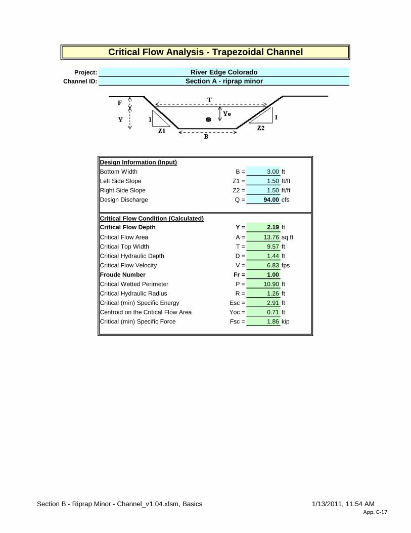
Design Information (Input)Bottom Width B = 3.00 ft Left Side Slope Z1 = 1.50 ft/ftRight Side Slope Z2 = 1.50 ft/ftDesign Discharge Q = 94.00 cfs
Critical Flow Condition (Calculated)Critical Flow Depth Y = 2.19 ftCritical Flow Area A = 13.76 sq ftCritical Top Width T = 9.57 ftCritical Hydraulic Depth D = 1.44 ftCritical Flow Velocity V = 6.83 fpsFroude Number Fr = 1.00Critical Wetted Perimeter P = 10.90 ftCritical Hydraulic Radius R = 1.26 ftCritical (min) Specific Energy Esc = 2.91 ftCentroid on the Critical Flow Area Yoc = 0.71 ftCritical (min) Specific Force Fsc = 1.86 kip
Critical Flow Analysis - Trapezoidal Channel
River Edge ColoradoSection A - riprap minor
Section B - Riprap Minor - Channel_v1.04.xlsm, Basics 1/13/2011, 11:54 AMApp. C-17

Project:Channel ID:
Design Information (Input)
Channel Invert Slope So = 0.0050 ft/ftManning's n n = 0.035 Bottom Width B = 3.00 ft Left Side Slope Z1 = 1.50 ft/ftRight Side Slope Z2 = 1.50 ft/ftFreeboard Height F = 0.50 ftDesign Water Depth Y = 3.00 ft
Normal Flow Condtion (Calculated) Discharge Q = 93.75 cfsFroude Number Fr = 0.54Flow Velocity V = 4.17 fpsFlow Area A = 22.50 sq ftTop Width T = 12.00 ftWetted Perimeter P = 13.82 ftHydraulic Radius R = 1.63 ftHydraulic Depth D = 1.88 ftSpecific Energy Es = 3.27 ftCentroid of Flow Area Yo = 1.19 ftSpecific Force Fs = 2.43 kip
Normal Flow Analysis - Trapezoidal Channel
River Edge ColoradoSection C - Riprap Major
Section A - Riprap Major_UD-Channel_v1.04.xlsm, Basics 1/13/2011, 11:54 AMApp. C-18
Project:Channel ID:
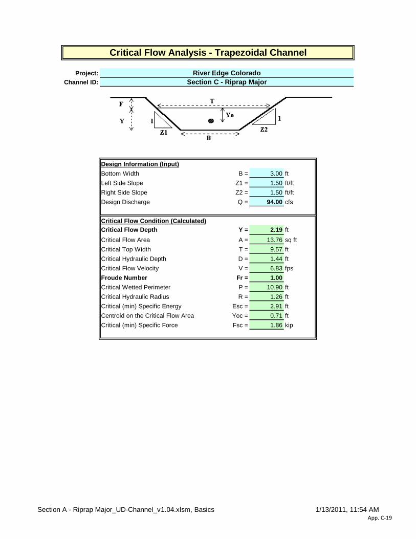
Design Information (Input)Bottom Width B = 3.00 ft Left Side Slope Z1 = 1.50 ft/ftRight Side Slope Z2 = 1.50 ft/ftDesign Discharge Q = 94.00 cfs
Critical Flow Condition (Calculated)Critical Flow Depth Y = 2.19 ftCritical Flow Area A = 13.76 sq ftCritical Top Width T = 9.57 ftCritical Hydraulic Depth D = 1.44 ftCritical Flow Velocity V = 6.83 fpsFroude Number Fr = 1.00Critical Wetted Perimeter P = 10.90 ftCritical Hydraulic Radius R = 1.26 ftCritical (min) Specific Energy Esc = 2.91 ftCentroid on the Critical Flow Area Yoc = 0.71 ftCritical (min) Specific Force Fsc = 1.86 kip
Critical Flow Analysis - Trapezoidal Channel
River Edge ColoradoSection C - Riprap Major
Section A - Riprap Major_UD-Channel_v1.04.xlsm, Basics 1/13/2011, 11:54 AMApp. C-19

Project:Channel ID:
Design Information (Input)Channel Invert Slope So = 0.01400 ft/ft Left Overbank Bottom Width BL = 1.00 ft
Left Overbank Side Slope ZL = 4.00 ft/ftLow Flow Channel Bottom Width Bm = 3.00 ft Left Overbank Manning's n n-left = 0.0400Low Flow Channel Left Side Slope Z1 = 0.00 ft/ft Right Overbank Bottom Width BR = 1.00 ftLow Flow Channel Right Side Slope Z2 = 0.00 ft/ft Right Overbank Side Slope ZR = 4.00 ft/ftLow Flow Channel Manning's Nn for Qd n-lf = 0.0130 Right Overbank Manning's n n-right = 0.0400Low Flow Channel Manning's Nn for Q100 n-m-Q100 = 0.0200(See USDCM Vol. II, n vs. Depth Graph)Low Flow Channel Bank-full depth Ym = 0.50 ft Overbank Flow Depth Yob (Y - Ym) Yob = 1.00 ft
Low Flow Channel Condition for Qd Low Flow Channel Flow Condition for Q100Top width Tlf = 3.0 ft Top width Tm = 3.0 ftFlow area Alf = 1.5 sq ft Flow area Am = 4.5 sq ftWetted perimeter Plf = 4.0 ft Wetted perimeter Pm = 4.0 ftDischarge (Calculated) Qlf = 10.6 cfs Discharge Qm = 42.9 cfsVelocity Vlf= 7.1 fps Velocity Vm = 9.5 fpsFroude number Fr-lf = 1.76 Froude number Frm = 1.37Qd Critical Velocity Vlfc = 4.84 fps 100-Yr. Critical Velocity Vmc = 5.7 fpsQd Critical Depth Ylfc = 0.73 ft 100-Yr. Critical Depth Ymc = 1.5 ft
Left Overbank Flow Condition for Q100 Right Overbank Flow Condition for Q100Top width TL = 5.0 ft Top width TR = 5.0 ftFlow area AL = 3.0000 sq ft Flow area AR = 3.0000 sq ftWetted perimeter PL = 5.1200 ft Wetted perimeter PR = 5.1200 ftDischarge QL = 9.3 cfs Discharge QR = 9.3 cfsVelocity VL = 3.1 fps Velocity VR = 3.1 fpsFroude number FrL = 0.70 Froude number FrR = 0.70100-Yr. Critical Velocity VLc = 4.1 fps 100-Yr. Critical Velocity VRc = 4.1 fps100-Yr. Critical Depth in Overbanks YLc = 0.8 ft 100-Yr. Critical Depth in Overbanks YRc = 0.8 ft
Composite Cross-Section Flow Condition for Q100Top width T = 13.0 ft Discharge Q = 61.4 cfsChannel Depth Y Y = 1.50 ft Velocity V = 5.9 fpsFlow area A = 10.5 sq ft Froude number Fr = 1.15Wetted perimeter P = 14.3 ft 100-Yr. Critical Velocity Vc = 5.2 fpsCross-Sectional Manning's n (Calculated) n = 0.0246 100-Yr. Critical Depth in Overbanks Yc = 1.09 ft
River Edge Colorado
Capacity Analysis of Composite Channel
Yob
Ym
Bm
N-left N-lf N-right
Right Overbank AreaLow Flow ChannelLeft Overbank Area
Y Yc Z21
Z11
ZL1
ZR1
AlternateOverbank
Toe Protection
BL BR
Section D - Grass Lined trickle major_UD-Channel_v1.04.xlsm, Composite Analysis 1/13/2011, 11:56 AMApp. C-20

Project: Basin ID:
1.92 X
Design Information (Input):Circular Culvert: Barrel Diameter in Inches D = 24.00 inches
Inlet Edge Type (choose from pull-down list) Grooved End with Headwall OR: OR:
Box Culvert: Barrel Height (Rise) in Feet Height (Rise) = ft.Barrel Width (Span) in Feet Width (Span) = ft.Inlet Edge Type (choose from pull-down list) Square Edge w/ 30-78 deg. Flared Wingwall
Number of Barrels No = 2Inlet Elevation at Culvert Invert Inlet Elev = 6012.5 ft. elev. Outlet Elevation at Culvert Invert OR Slope of Culvert (ft v./ft h.) Slope = 0.014 ft vert. / ft horiz.Culvert Length in Feet L = 45.00 ft.Manning's Roughness n = 0.0130Bend Loss Coefficient Kb = 0.00Exit Loss Coefficient Kx = 1.00
Design Information (calculated):Entrance Loss Coefficient Ke = 0.20 Friction Loss Coefficient Kf = 0.56 Sum of All Loss Coefficients Ks = 1.76Orifice Inlet Condition Coefficient Cd = 0.99 Minimum Energy Condition Coefficient KElow = -0.6439
Calculations of Culvert Capacity (output):Water Surface Tailwater Culvert Culvert Controlling Inlet
Elevation Surface Inlet-Control Outlet-Control Culvert EquationElevation Flowrate Flowrate Flowrate Used:
ft cfs cfs cfs(ft., linked) (input if known) (output) (output) (output) (output)
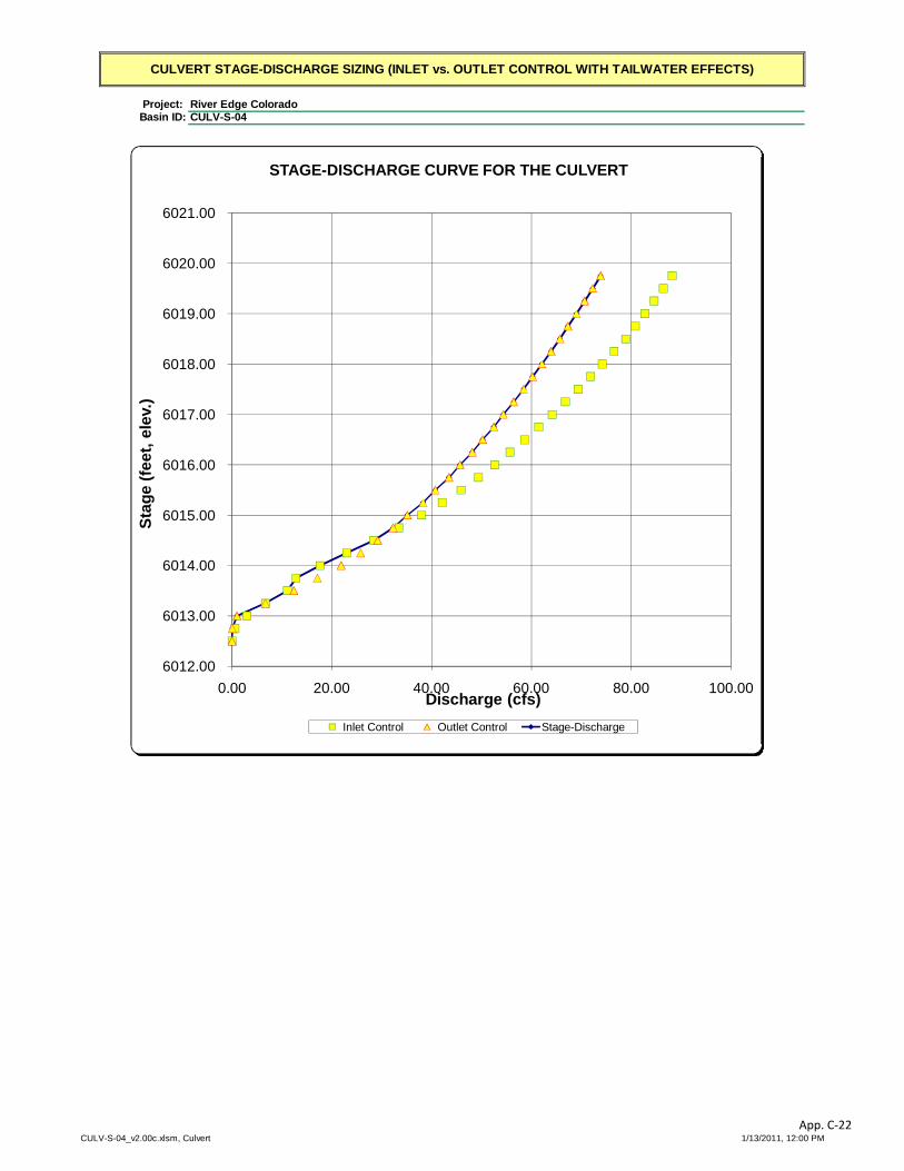
6012.50 0.00 0.00 0.00 No flow (WS < inlet)6012.75 0.56 0.04 0.04 min. energy equation6013.00 2.98 0.98 0.98 min. energy equation6013.25 6.68 6.68 6.68 min. energy equation6013.50 11.10 12.38 11.10 min. energy equation6013.75 12.86 17.10 12.86 regression equation6014.00 17.64 21.86 17.64 regression equation6014.25 23.00 25.78 23.00 regression equation6014.50 28.40 29.20 28.40 regression equation6014.75 33.44 32.28 32.28 regression equation6015.00 38.00 35.14 35.14 regression equation6015.25 42.12 38.28 38.28 regression equation6015.50 45.88 40.74 40.74 regression equation6015.75 49.36 43.48 43.48 regression equation6016.00 52.62 45.70 45.70 regression equation6016.25 55.70 48.16 48.16 regression equation6016.50 58.64 50.22 50.22 regression equation6016.75 61.44 52.46 52.46 regression equation6017.00 64.16 54.38 54.38 regression equation6017.25 66.78 56.46 56.46 regression equation6017.50 69.34 58.46 58.46 regression equation6017.75 71.82 60.22 60.22 regression equation6018.00 74.22 62.12 62.12 regression equation6018.25 76.58 63.94 63.94 regression equation6018.50 78.86 65.72 65.72 orifice equation6018.75 80.84 67.32 67.32 orifice equation6019.00 82.74 69.02 69.02 orifice equation6019.25 84.60 70.68 70.68 orifice equation6019.50 86.42 72.28 72.28 orifice equation6019.75 88.20 73.86 73.86 orifice equation
Processing Time: 1.92 seconds
CULVERT STAGE-DISCHARGE SIZING (INLET vs. OUTLET CONTROL WITH TAILWATER EFFECTS)
River Edge ColoradoCULV-S-04
CULV-S-04_v2.00c.xlsm, Culvert 1/13/2011, 12:00 PMApp. C-21
Project: Basin ID:
CULVERT STAGE-DISCHARGE SIZING (INLET vs. OUTLET CONTROL WITH TAILWATER EFFECTS)
River Edge ColoradoCULV-S-04
6012.00
6013.00
6014.00
6015.00
6016.00
6017.00
6018.00
6019.00
6020.00
6021.00
0.00 20.00 40.00 60.00 80.00 100.00
Stag
e (fe
et, e
lev.
)
Discharge (cfs)
STAGE-DISCHARGE CURVE FOR THE CULVERT
Inlet Control Outlet Control Stage-Discharge
CULV-S-04_v2.00c.xlsm, Culvert 1/13/2011, 12:00 PMApp. C-22

Project: Basin ID:
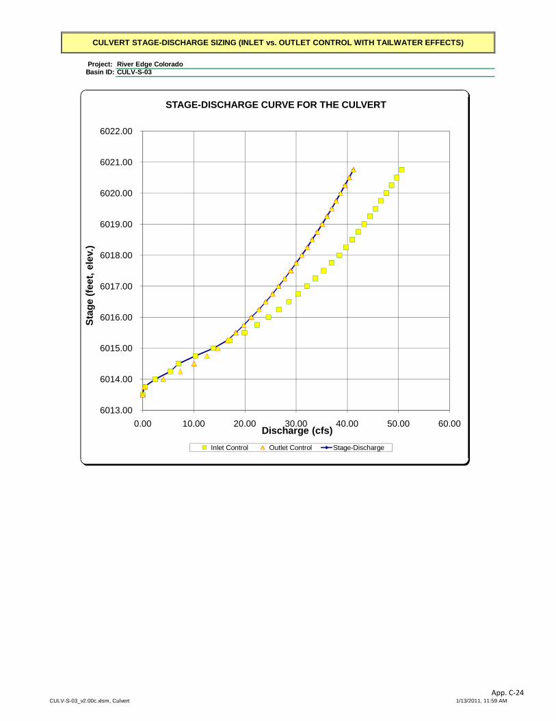
1.22 X
Design Information (Input):Circular Culvert: Barrel Diameter in Inches D = 18.00 inches
Inlet Edge Type (choose from pull-down list) Grooved End with Headwall OR: OR:
Box Culvert: Barrel Height (Rise) in Feet Height (Rise) = ft.Barrel Width (Span) in Feet Width (Span) = ft.Inlet Edge Type (choose from pull-down list) Square Edge w/ 30-78 deg. Flared Wingwall
Number of Barrels No = 2Inlet Elevation at Culvert Invert Inlet Elev = 6013.5 ft. elev. Outlet Elevation at Culvert Invert OR Slope of Culvert (ft v./ft h.) Slope = 0.013 ft vert. / ft horiz.Culvert Length in Feet L = 45.00 ft.Manning's Roughness n = 0.0130Bend Loss Coefficient Kb = 0.00Exit Loss Coefficient Kx = 1.00
Design Information (calculated):Entrance Loss Coefficient Ke = 0.20 Friction Loss Coefficient Kf = 0.82 Sum of All Loss Coefficients Ks = 2.02Orifice Inlet Condition Coefficient Cd = 0.99 Minimum Energy Condition Coefficient KElow = -0.6437
Calculations of Culvert Capacity (output):Water Surface Tailwater Culvert Culvert Controlling Inlet
Elevation Surface Inlet-Control Outlet-Control Culvert EquationElevation Flowrate Flowrate Flowrate Used:
ft cfs cfs cfs(ft., linked) (input if known) (output) (output) (output) (output)
6013.50 0.00 0.00 0.00 No flow (WS < inlet)6013.75 0.48 0.28 0.28 min. energy equation6014.00 2.44 4.04 2.44 min. energy equation6014.25 5.42 7.32 5.42 min. energy equation6014.50 7.00 10.02 7.00 regression equation6014.75 10.32 12.56 10.32 regression equation6015.00 13.84 14.68 13.84 regression equation6015.25 17.06 16.54 16.54 regression equation6015.50 19.88 18.22 18.22 regression equation6015.75 22.36 19.76 19.76 regression equation6016.00 24.60 21.22 21.22 regression equation6016.25 26.64 22.74 22.74 regression equation6016.50 28.58 24.04 24.04 regression equation6016.75 30.38 25.38 25.38 regression equation6017.00 32.12 26.56 26.56 regression equation6017.25 33.78 27.78 27.78 regression equation6017.50 35.38 28.92 28.92 regression equation6017.75 36.94 30.02 30.02 regression equation6018.00 38.44 31.10 31.10 orifice equation6018.25 39.74 32.16 32.16 orifice equation6018.50 40.96 33.12 33.12 orifice equation6018.75 42.14 34.12 34.12 orifice equation6019.00 43.30 35.08 35.08 orifice equation6019.25 44.42 36.02 36.02 orifice equation6019.50 45.52 36.94 36.94 orifice equation6019.75 46.58 37.80 37.80 orifice equation6020.00 47.62 38.66 38.66 orifice equation6020.25 48.66 39.52 39.52 orifice equation6020.50 49.66 40.36 40.36 orifice equation6020.75 50.64 41.18 41.18 orifice equation
Processing Time: 1.22 seconds
CULVERT STAGE-DISCHARGE SIZING (INLET vs. OUTLET CONTROL WITH TAILWATER EFFECTS)
River Edge ColoradoCULV-S-03
CULV-S-03_v2.00c.xlsm, Culvert 1/13/2011, 11:59 AMApp. C-23
Project: Basin ID:
CULVERT STAGE-DISCHARGE SIZING (INLET vs. OUTLET CONTROL WITH TAILWATER EFFECTS)
River Edge ColoradoCULV-S-03
6013.00
6014.00
6015.00
6016.00
6017.00
6018.00
6019.00
6020.00
6021.00
6022.00
0.00 10.00 20.00 30.00 40.00 50.00 60.00
Stag
e (fe
et, e
lev.
)
Discharge (cfs)
STAGE-DISCHARGE CURVE FOR THE CULVERT
Inlet Control Outlet Control Stage-Discharge
CULV-S-03_v2.00c.xlsm, Culvert 1/13/2011, 11:59 AMApp. C-24

Project: Basin ID:
3.38 X
Design Information (Input):Circular Culvert: Barrel Diameter in Inches D = 36.00 inches
Inlet Edge Type (choose from pull-down list) Grooved End with Headwall OR: OR:
Box Culvert: Barrel Height (Rise) in Feet Height (Rise) = ft.Barrel Width (Span) in Feet Width (Span) = ft.Inlet Edge Type (choose from pull-down list) Square Edge w/ 30-78 deg. Flared Wingwall
Number of Barrels No = 2Inlet Elevation at Culvert Invert Inlet Elev = 5989.5 ft. elev. Outlet Elevation at Culvert Invert OR Slope of Culvert (ft v./ft h.) Slope = 0.01 ft vert. / ft horiz.Culvert Length in Feet L = 45.00 ft.Manning's Roughness n = 0.0130Bend Loss Coefficient Kb = 0.00Exit Loss Coefficient Kx = 1.00
Design Information (calculated):Entrance Loss Coefficient Ke = 0.20 Friction Loss Coefficient Kf = 0.32 Sum of All Loss Coefficients Ks = 1.52Orifice Inlet Condition Coefficient Cd = 0.99 Minimum Energy Condition Coefficient KElow = -0.6367
Calculations of Culvert Capacity (output):Water Surface Tailwater Culvert Culvert Controlling Inlet
Elevation Surface Inlet-Control Outlet-Control Culvert EquationElevation Flowrate Flowrate Flowrate Used:
ft cfs cfs cfs(ft., linked) (input if known) (output) (output) (output) (output)
5989.50 0.00 0.00 0.00 No flow (WS < inlet)5989.75 0.74 0.04 0.04 min. energy equation5990.00 2.62 0.02 0.02 min. energy equation5990.25 8.06 0.02 0.02 min. energy equation5990.50 13.62 0.02 0.02 min. energy equation5990.75 24.00 2.64 2.64 min. energy equation5991.00 30.52 13.62 13.62 min. energy equation5991.25 31.24 24.00 24.00 regression equation5991.50 39.32 35.94 35.94 regression equation5991.75 48.34 46.02 46.02 regression equation5992.00 58.08 54.90 54.90 regression equation5992.25 68.12 63.08 63.08 regression equation5992.50 78.00 69.92 69.92 regression equation5992.75 87.40 76.20 76.20 regression equation5993.00 96.22 84.16 84.16 regression equation5993.25 104.46 89.56 89.56 regression equation5993.50 112.14 96.14 96.14 regression equation5993.75 119.38 101.24 101.24 regression equation5994.00 126.20 107.36 107.36 regression equation5994.25 132.68 111.82 111.82 regression equation5994.50 138.86 117.38 117.38 regression equation5994.75 144.80 121.58 121.58 regression equation5995.00 150.52 126.72 126.72 regression equation5995.25 156.04 131.66 131.66 regression equation5995.50 161.40 135.52 135.52 regression equation5995.75 166.60 140.14 140.14 regression equation5996.00 171.68 144.62 144.62 regression equation5996.25 176.64 148.24 148.24 regression equation5996.50 181.50 152.48 152.48 regression equation5996.75 186.24 156.62 156.62 regression equation
Processing Time: 3.38 seconds
CULVERT STAGE-DISCHARGE SIZING (INLET vs. OUTLET CONTROL WITH TAILWATER EFFECTS)
River Edge ColoradoCULV-S-02
CULV-S-02_v2.00c.xlsm, Culvert 1/13/2011, 11:58 AMApp. C-25

Project: Basin ID:
CULVERT STAGE-DISCHARGE SIZING (INLET vs. OUTLET CONTROL WITH TAILWATER EFFECTS)
River Edge ColoradoCULV-S-02
5989.00
5990.00
5991.00
5992.00
5993.00
5994.00
5995.00
5996.00
5997.00
5998.00
0.00 50.00 100.00 150.00 200.00
Stag
e (fe
et, e
lev.
)
Discharge (cfs)
STAGE-DISCHARGE CURVE FOR THE CULVERT
Inlet Control Outlet Control Stage-Discharge
CULV-S-02_v2.00c.xlsm, Culvert 1/13/2011, 11:58 AMApp. C-26

Project: Basin ID:
3.45 X
Design Information (Input):Circular Culvert: Barrel Diameter in Inches D = 36.00 inches
Inlet Edge Type (choose from pull-down list) Grooved End with Headwall OR: OR:
Box Culvert: Barrel Height (Rise) in Feet Height (Rise) = ft.Barrel Width (Span) in Feet Width (Span) = ft.Inlet Edge Type (choose from pull-down list) Square Edge w/ 30-78 deg. Flared Wingwall
Number of Barrels No = 2Inlet Elevation at Culvert Invert Inlet Elev = 5983.5 ft. elev. Outlet Elevation at Culvert Invert OR Slope of Culvert (ft v./ft h.) Slope = 0.01 ft vert. / ft horiz.Culvert Length in Feet L = 45.00 ft.Manning's Roughness n = 0.0130Bend Loss Coefficient Kb = 0.00Exit Loss Coefficient Kx = 1.00
Design Information (calculated):Entrance Loss Coefficient Ke = 0.20 Friction Loss Coefficient Kf = 0.32 Sum of All Loss Coefficients Ks = 1.52Orifice Inlet Condition Coefficient Cd = 0.99 Minimum Energy Condition Coefficient KElow = -0.6367
Calculations of Culvert Capacity (output):Water Surface Tailwater Culvert Culvert Controlling Inlet
Elevation Surface Inlet-Control Outlet-Control Culvert EquationElevation Flowrate Flowrate Flowrate Used:
ft cfs cfs cfs(ft., linked) (input if known) (output) (output) (output) (output)
5983.50 0.00 0.00 0.00 No flow (WS < inlet)5983.75 0.74 0.04 0.04 min. energy equation5984.00 2.62 0.02 0.02 min. energy equation5984.25 8.06 0.02 0.02 min. energy equation5984.50 13.62 0.02 0.02 min. energy equation5984.75 24.00 2.64 2.64 min. energy equation5985.00 30.52 13.62 13.62 min. energy equation5985.25 31.24 24.00 24.00 regression equation5985.50 39.32 35.94 35.94 regression equation5985.75 48.34 46.02 46.02 regression equation5986.00 58.08 54.90 54.90 regression equation5986.25 68.12 63.08 63.08 regression equation5986.50 78.00 69.92 69.92 regression equation5986.75 87.40 76.20 76.20 regression equation5987.00 96.22 84.16 84.16 regression equation5987.25 104.46 89.56 89.56 regression equation5987.50 112.14 96.14 96.14 regression equation5987.75 119.38 101.24 101.24 regression equation5988.00 126.20 107.36 107.36 regression equation5988.25 132.68 111.82 111.82 regression equation5988.50 138.86 117.38 117.38 regression equation5988.75 144.80 121.58 121.58 regression equation5989.00 150.52 126.72 126.72 regression equation5989.25 156.04 131.66 131.66 regression equation5989.50 161.40 135.52 135.52 regression equation5989.75 166.60 140.14 140.14 regression equation5990.00 171.68 144.62 144.62 regression equation5990.25 176.64 148.24 148.24 regression equation5990.50 181.50 152.48 152.48 regression equation5990.75 186.24 156.62 156.62 regression equation
Processing Time: 3.45 seconds
CULVERT STAGE-DISCHARGE SIZING (INLET vs. OUTLET CONTROL WITH TAILWATER EFFECTS)
River Edge ColoradoCULV-S-01
CULV-S-01_v2.00c.xlsm, Culvert 1/13/2011, 11:57 AMApp. C-27

Project: Basin ID:
CULVERT STAGE-DISCHARGE SIZING (INLET vs. OUTLET CONTROL WITH TAILWATER EFFECTS)
River Edge ColoradoCULV-S-01
5983.00
5984.00
5985.00
5986.00
5987.00
5988.00
5989.00
5990.00
5991.00
5992.00
0.00 50.00 100.00 150.00 200.00
Stag
e (fe
et, e
lev.
)
Discharge (cfs)
STAGE-DISCHARGE CURVE FOR THE CULVERT
Inlet Control Outlet Control Stage-Discharge
CULV-S-01_v2.00c.xlsm, Culvert 1/13/2011, 11:57 AMApp. C-28

Project: Basin ID:
3.42 X
Design Information (Input):Circular Culvert: Barrel Diameter in Inches D = 36.00 inches
Inlet Edge Type (choose from pull-down list) Grooved End with Headwall OR: OR:
Box Culvert: Barrel Height (Rise) in Feet Height (Rise) = ft.Barrel Width (Span) in Feet Width (Span) = ft.Inlet Edge Type (choose from pull-down list) Square Edge w/ 30-78 deg. Flared Wingwall
Number of Barrels No = 2Inlet Elevation at Culvert Invert Inlet Elev = 6008 ft. elev. Outlet Elevation at Culvert Invert OR Slope of Culvert (ft v./ft h.) Slope = 0.005 ft vert. / ft horiz.Culvert Length in Feet L = 45.00 ft.Manning's Roughness n = 0.0130Bend Loss Coefficient Kb = 0.00Exit Loss Coefficient Kx = 1.00
Design Information (calculated):Entrance Loss Coefficient Ke = 0.20 Friction Loss Coefficient Kf = 0.32 Sum of All Loss Coefficients Ks = 1.52Orifice Inlet Condition Coefficient Cd = 0.99 Minimum Energy Condition Coefficient KElow = -0.3672
Calculations of Culvert Capacity (output):Water Surface Tailwater Culvert Culvert Controlling Inlet
Elevation Surface Inlet-Control Outlet-Control Culvert EquationElevation Flowrate Flowrate Flowrate Used:
ft cfs cfs cfs(ft., linked) (input if known) (output) (output) (output) (output)
6008.00 0.00 0.00 0.00 No flow (WS < inlet)6008.25 0.74 0.04 0.04 min. energy equation6008.50 2.62 0.02 0.02 min. energy equation6008.75 6.66 0.02 0.02 min. energy equation6009.00 13.44 0.02 0.02 min. energy equation6009.25 18.42 0.02 0.02 min. energy equation6009.50 28.28 2.64 2.64 min. energy equation6009.75 31.02 13.62 13.62 regression equation6010.00 39.08 24.00 24.00 regression equation6010.25 48.06 37.68 37.68 regression equation6010.50 57.78 46.02 46.02 regression equation6010.75 67.82 54.90 54.90 regression equation6011.00 77.70 64.08 64.08 regression equation6011.25 87.12 70.82 70.82 regression equation6011.50 95.96 77.04 77.04 regression equation6011.75 104.22 84.92 84.92 regression equation6012.00 111.92 90.26 90.26 regression equation6012.25 119.16 96.14 96.14 regression equation6012.50 126.00 101.88 101.88 regression equation6012.75 132.48 107.68 107.68 regression equation6013.00 138.68 112.38 112.38 regression equation6013.25 144.62 117.92 117.92 regression equation6013.50 150.34 122.10 122.10 regression equation6013.75 155.88 127.22 127.22 regression equation6014.00 161.24 132.14 132.14 regression equation6014.25 166.44 135.98 135.98 regression equation6014.50 171.52 140.60 140.60 regression equation6014.75 176.50 145.06 145.06 regression equation6015.00 181.34 148.68 148.68 regression equation6015.25 186.10 152.90 152.90 regression equation
Processing Time: 3.42 seconds
CULVERT STAGE-DISCHARGE SIZING (INLET vs. OUTLET CONTROL WITH TAILWATER EFFECTS)
River Edge ColoradoCULV-N-01
CULV-N-01_v2.00c.xlsm, Culvert 1/13/2011, 11:57 AMApp. C-29
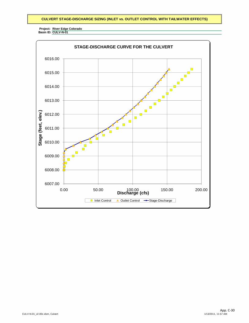
Project: Basin ID:
CULVERT STAGE-DISCHARGE SIZING (INLET vs. OUTLET CONTROL WITH TAILWATER EFFECTS)
River Edge ColoradoCULV-N-01
6007.00
6008.00
6009.00
6010.00
6011.00
6012.00
6013.00
6014.00
6015.00
6016.00
0.00 50.00 100.00 150.00 200.00
Stag
e (fe
et, e
lev.
)
Discharge (cfs)
STAGE-DISCHARGE CURVE FOR THE CULVERT
Inlet Control Outlet Control Stage-Discharge
CULV-N-01_v2.00c.xlsm, Culvert 1/13/2011, 11:57 AMApp. C-30

Project: Basin ID:
1.97 X
Design Information (Input):Circular Culvert: Barrel Diameter in Inches D = 24.00 inches
Inlet Edge Type (choose from pull-down list) Grooved End with Headwall OR: OR:
Box Culvert: Barrel Height (Rise) in Feet Height (Rise) = ft.Barrel Width (Span) in Feet Width (Span) = ft.Inlet Edge Type (choose from pull-down list) Square Edge w/ 30-78 deg. Flared Wingwall
Number of Barrels No = 2Inlet Elevation at Culvert Invert Inlet Elev = 6015 ft. elev. Outlet Elevation at Culvert Invert OR Slope of Culvert (ft v./ft h.) Slope = 0.014 ft vert. / ft horiz.Culvert Length in Feet L = 45.00 ft.Manning's Roughness n = 0.0130Bend Loss Coefficient Kb = 0.00Exit Loss Coefficient Kx = 1.00
Design Information (calculated):Entrance Loss Coefficient Ke = 0.20 Friction Loss Coefficient Kf = 0.56 Sum of All Loss Coefficients Ks = 1.76Orifice Inlet Condition Coefficient Cd = 0.99 Minimum Energy Condition Coefficient KElow = -0.6439
Calculations of Culvert Capacity (output):Water Surface Tailwater Culvert Culvert Controlling Inlet
Elevation Surface Inlet-Control Outlet-Control Culvert EquationElevation Flowrate Flowrate Flowrate Used:
ft cfs cfs cfs(ft., linked) (input if known) (output) (output) (output) (output)
6015.00 0.00 0.00 0.00 No flow (WS < inlet)6015.25 0.56 0.04 0.04 min. energy equation6015.50 2.98 0.98 0.98 min. energy equation6015.75 6.68 6.68 6.68 min. energy equation6016.00 11.10 12.38 11.10 min. energy equation6016.25 12.86 17.10 12.86 regression equation6016.50 17.64 21.86 17.64 regression equation6016.75 23.00 25.78 23.00 regression equation6017.00 28.40 29.20 28.40 regression equation6017.25 33.44 32.28 32.28 regression equation6017.50 38.00 35.14 35.14 regression equation6017.75 42.12 38.28 38.28 regression equation6018.00 45.88 40.74 40.74 regression equation6018.25 49.36 43.48 43.48 regression equation6018.50 52.62 45.70 45.70 regression equation6018.75 55.70 48.16 48.16 regression equation6019.00 58.64 50.22 50.22 regression equation6019.25 61.44 52.46 52.46 regression equation6019.50 64.16 54.38 54.38 regression equation6019.75 66.78 56.46 56.46 regression equation6020.00 69.34 58.46 58.46 regression equation6020.25 71.82 60.22 60.22 regression equation6020.50 74.22 62.12 62.12 regression equation6020.75 76.58 63.94 63.94 regression equation6021.00 78.86 65.72 65.72 orifice equation6021.25 80.84 67.32 67.32 orifice equation6021.50 82.74 69.02 69.02 orifice equation6021.75 84.60 70.68 70.68 orifice equation6022.00 86.42 72.28 72.28 orifice equation6022.25 88.20 73.86 73.86 orifice equation
Processing Time: 1.97 seconds
CULVERT STAGE-DISCHARGE SIZING (INLET vs. OUTLET CONTROL WITH TAILWATER EFFECTS)
River Edge ColoradoCULV-S-05
CULV-S-05_v2.00c.xlsm, Culvert 1/13/2011, 12:01 PMApp. C-31
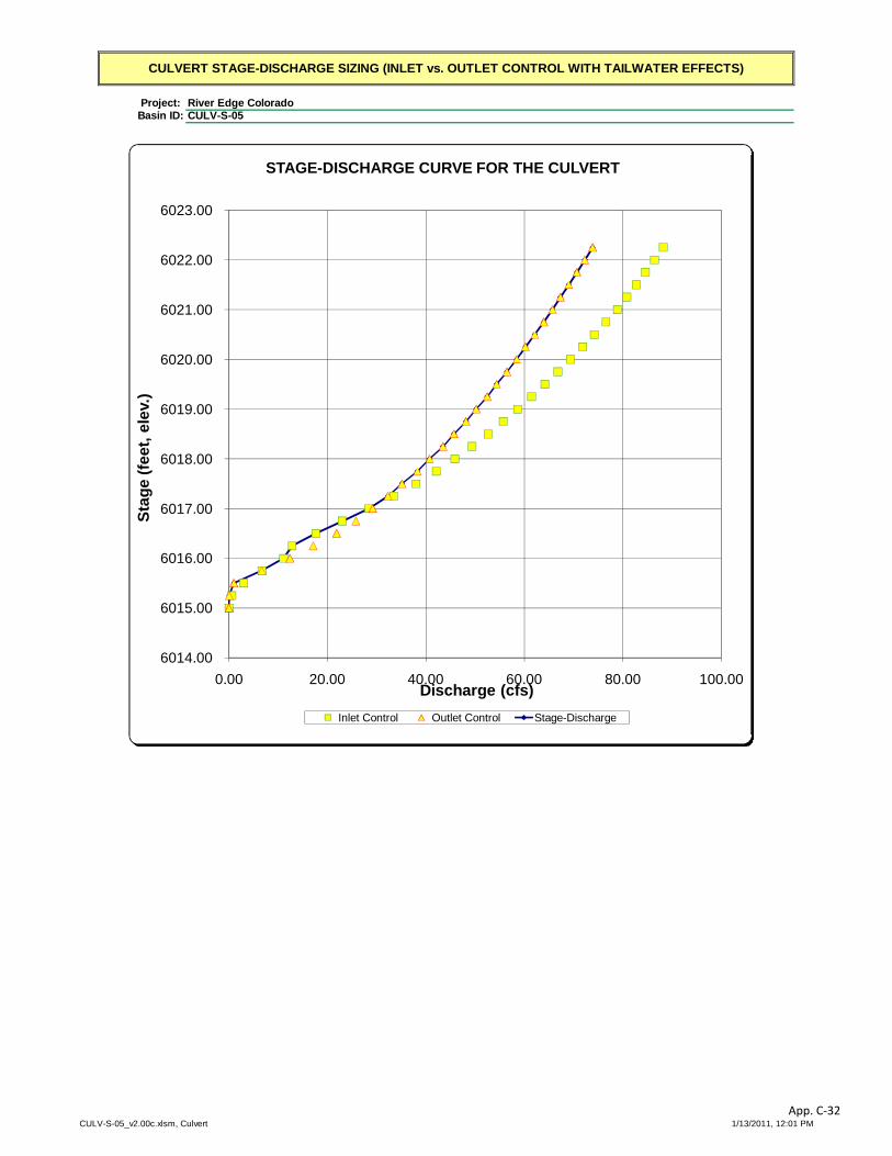
Project: Basin ID:
CULVERT STAGE-DISCHARGE SIZING (INLET vs. OUTLET CONTROL WITH TAILWATER EFFECTS)
River Edge ColoradoCULV-S-05
6014.00
6015.00
6016.00
6017.00
6018.00
6019.00
6020.00
6021.00
6022.00
6023.00
0.00 20.00 40.00 60.00 80.00 100.00
Stag
e (fe
et, e
lev.
)
Discharge (cfs)
STAGE-DISCHARGE CURVE FOR THE CULVERT
Inlet Control Outlet Control Stage-Discharge
CULV-S-05_v2.00c.xlsm, Culvert 1/13/2011, 12:01 PMApp. C-32