
Project Description S14
13
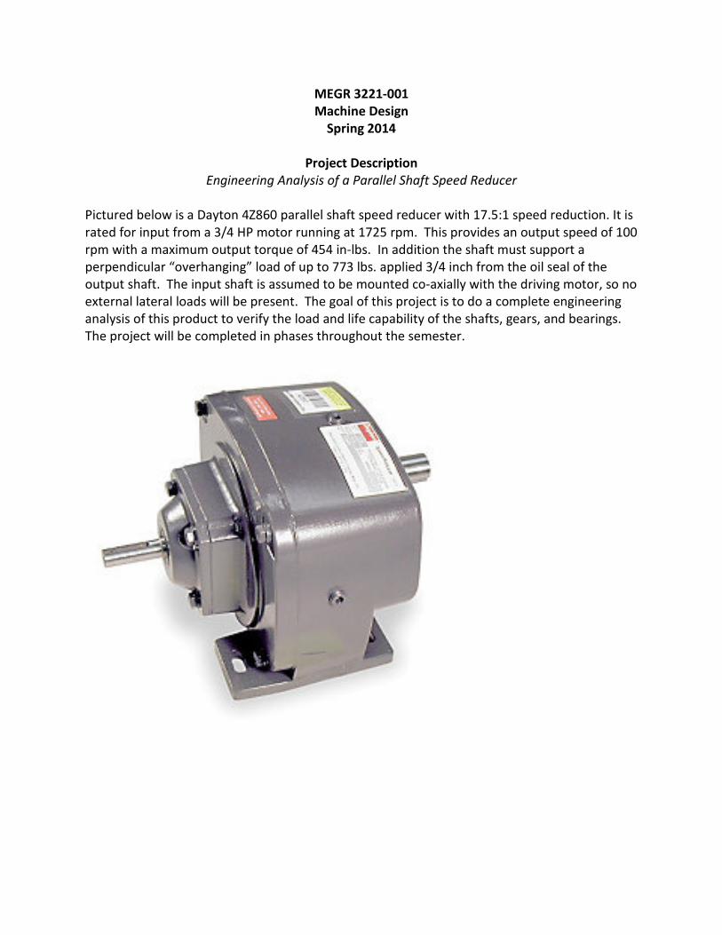
MEGR 3221-001 Machine Design Spring 2014 Project Description Engineering Analysis of a Parallel Shaft Speed Reducer Pictured below is a Dayton 4Z860 parallel shaft speed reducer with 17.5:1 speed reduction. It is rated for input from a 3/4 HP motor running at 1725 rpm. This provides an output speed of 100 rpm with a maximum output torque of 454 in-lbs. In addition the shaft must support a perpendicular “overhanging” load of up to 773 lbs. applied 3/4 inch from the oil seal of the output shaft. The input shaft is assumed to be mounted co-axially with the driving motor, so no external lateral loads will be present. The goal of this project is to do a complete engineering analysis of this product to verify the load and life capability of the shafts, gears, and bearings. The project will be completed in phases throughout the semester.
-
Upload
behinddaplate9 -
Category
Documents
-
view
145 -
download
0
description
aha
Transcript of Project Description S14
MEGR 3221-001
Machine Design
Spring 2014
Project Description
Engineering Analysis of a Parallel Shaft Speed Reducer
Pictured below is a Dayton 4Z860 parallel shaft speed reducer with 17.5:1 speed reduction. It is
rated for input from a 3/4 HP motor running at 1725 rpm. This provides an output speed of 100
rpm with a maximum output torque of 454 in-lbs. In addition the shaft must support a
perpendicular “overhanging” load of up to 773 lbs. applied 3/4 inch from the oil seal of the
output shaft. The input shaft is assumed to be mounted co-axially with the driving motor, so no
external lateral loads will be present. The goal of this project is to do a complete engineering
analysis of this product to verify the load and life capability of the shafts, gears, and bearings.
The project will be completed in phases throughout the semester.

Item
Speed Reducer
Type
Indirect Drive
Shaft Orientation
Parallel
Duty
Standard
Input RPM
1725
Nominal Output RPM
100
Overhung Load (Lb.)
773
Nominal Ratio
17.5:1
Max. Input HP
3/4
Max. Torque (In.-Lbs.)
454
Output Torque @ 1/4 HP (In.-Lb.)
151
Output Torque @ 1/3 HP (In.-Lb.)
201
Output Torque @ 1/2 HP (In.-Lb.)
302
Output Torque @ 3/4 HP (In.-Lb.)
454
Number of Stages
1
Rotation
Forward/Reverse
Lubrication
Kluber Food Grade
Oil Seal
Double Lip
Bearings
Ball
Pinion
Hardened Steel
Gearing
Helical and Spur
Finish
Powdered Epoxy Paint
Output Shaft Dia. (In.)
1
Output Shaft Height (In.)
4.88
Project Breakdown (100 pts total)
1. Load analysis (25 points) Due Feb. 13, 2014
Create free body diagrams of all of the shafts (with gears in place) in both the horizontal and vertical
planes. Use the manufacturer’s maximum load/torque ratings as inputs and compute the reaction
loads on each shaft at the bearing locations, and at each gear mesh point. Use the dimensional
layout and shaft dimensions supplied to determine the intersection points of all of the gears, and
the resulting force directions. Note that the manufacturer allows an “overhanging” load normal to
the shaft axis of up to 773 lbs on the output shaft at a point 1 inch outboard from the oil seal, but
does not specify the direction of the load. Create your free body diagrams for this load in its worst
case orientation, and justify the selected orientation. Consider how the loads will change if the
direction of input torque is reversed, and choose the worst case for analysis.
Deliverables:
a. Report describing the loading cases selected for analysis, with justification
b. Free body diagrams for all shafts in horizontal and vertical planes
c. Summary table showing all bearing loads and gear tooth loads
2. Shaft calculations (35 points) Due Mar. 25, 2014
For each shaft, input shaft, countershaft, and output shaft, draw the shear and bending moment
diagrams in both the horizontal and vertical planes. Use the shaft dimensions supplied, and the
forces from the solutions provided for Part 1. Determine the critical section or sections to be
analyzed for each shaft, taking into consideration any stress concentrations. Determine the range of
stresses at each critical location as the device operates under full load. We do not know the
material alloy or heat treatment used for these shafts, and therefore do not know the strength
properties. Select a steel alloy for each shaft that will result in infinite fatigue life with a factor of
safety of at least 2. Make reasonable assumptions needed to complete the analysis.
Deliverables:
a. Report on stress analysis for each shaft, with shear and bending moment diagrams if the
horizontal and vertical planes and identifying the stresses acting on the critical sections.
b. Material selection report for each shaft with accompanying fatigue life calculations,
identifying any assumptions used in the analysis.
3. Bearing life (15 points) Due Apr. 10, 2014
Each of the shafts is supported by a two ball bearings. The bearing model numbers are provided in
the dimensional drawings below. Consult the tables in the text for the basic static and dynamic load
ratings for each bearing. Determine the expected life of the bearing based on the loads computed
in Section 1. Make any reasonable assumptions required to complete the analysis.
Deliverables:
a. Analysis of bearing life for all bearings.
4. Gear calculations (25 points) Due Apr. 24, 2014
Analyze the pinion gears in each gearset using the tooth forces obtained from Part 1. The
manufacturer states that the steel gears have been induction hardened, but does not provide a
specific hardness. Assume that the steel pinions have been hardened to 500 Bhn, and find the
required face width for each pinion to provide infinite life with a Factor of Safety of at least 1.4,
based on both a Tooth Bending Analysis and a Surface Fatigue Analysis. Make any reasonable
assumptions required to complete the analysis.
Deliverables:
a. Report on pinion gear tooth analysis, identifying any assumptions used in the analysis.

Fig. 1. Speed reducer interior
Fig. 2. Speed reducer interior showing cover with countershaft and output shaft
Input Shaft
Support for countershaft bearing
Countershaft
Output shaft
Support for output shaft bearing
Output gear
Input gear – on countershaft
Output pinion – on countershaft
Housing
Cover

Fig. 3. Speed reducer interior from bottom showing input shaft pinion
Fig. 4. Speed reducer interior from bottom with output shaft removed
Input helical pinion – integral with input shaft
Input helical gear
Output pinion – integral with countershaft
Output gear
Countershaft
Output shaft front bearing support
Output shaft
Input shaft helical gear

Fig. 5. Speed reducer interior with countershaft and output shaft removed
Fig. 6. Speed reducer cover with shafts
Input shaft helical gear
Countershaft front bearing support
Countershaft
Output shaft
Output shaft
Countershaft
Input shaft helical pinion
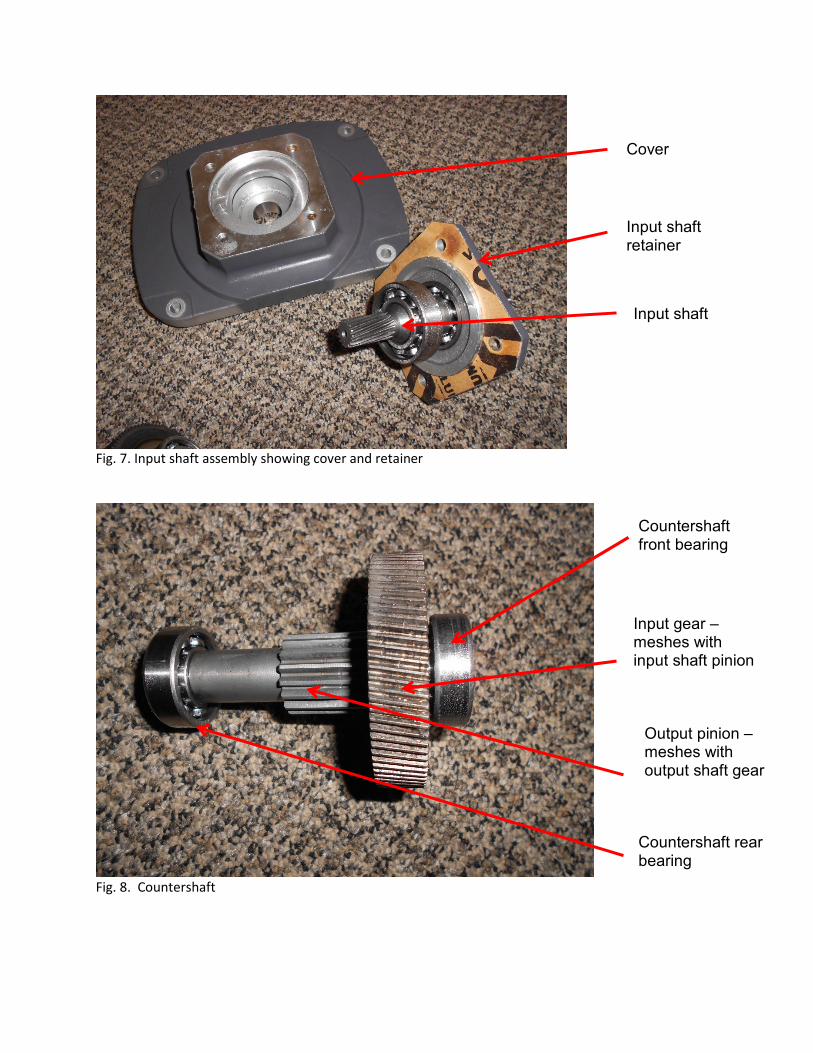
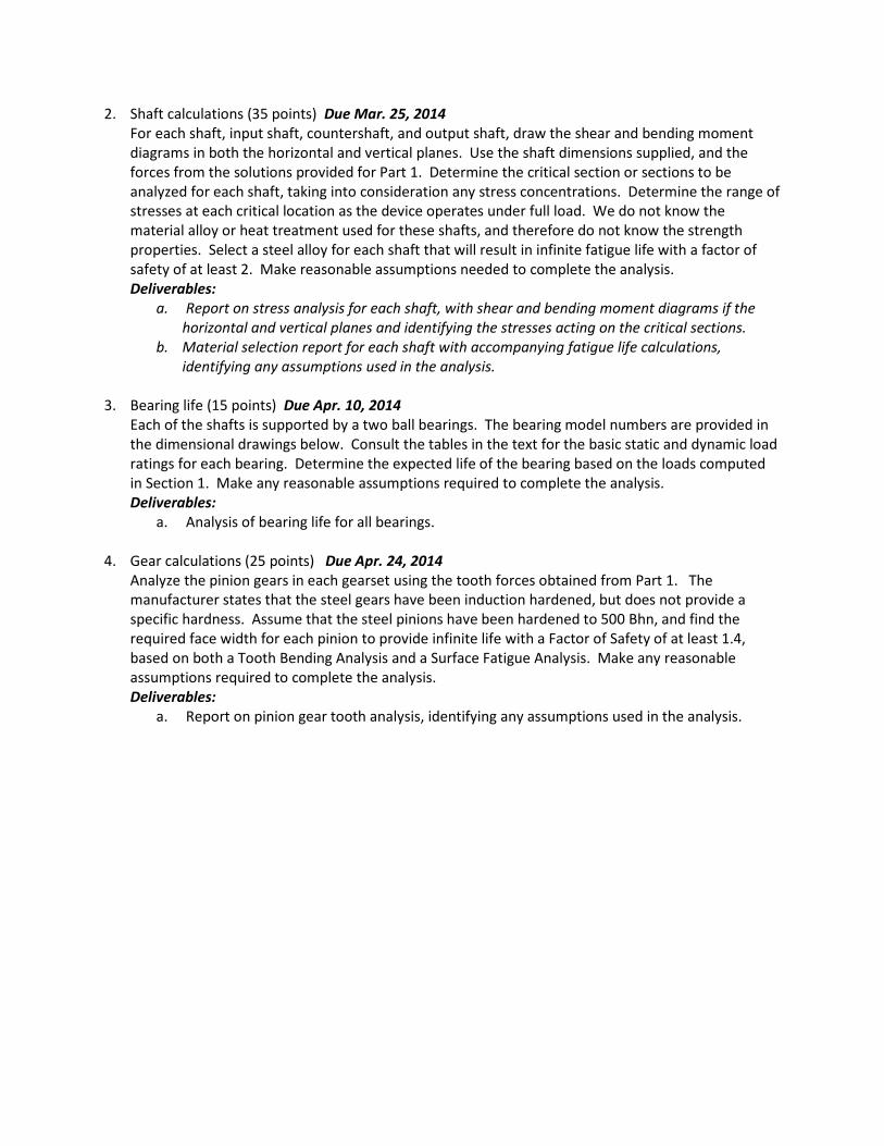
Fig. 7. Input shaft assembly showing cover and retainer
Fig. 8. Countershaft
Cover
Input shaft retainer
Input shaft
Countershaft front bearing
Input gear – meshes with input shaft pinion
Output pinion – meshes with output shaft gear
Countershaft rear bearing
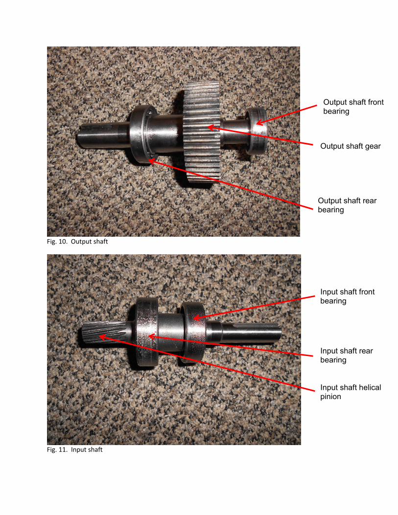
Fig. 10. Output shaft
Fig. 11. Input shaft
Output shaft front bearing
Output shaft gear
Output shaft rear bearing
Input shaft front bearing
Input shaft rear bearing
Input shaft helical pinion

Input Shaft dimensions (not to scale, all dimensions in inches):
5.95
2.05
2.18
2.87
1.20
2.95
1.40
3.44
1.55
4.00
1.65
4.07
Centerline of 204 BRG
0.677 DIA
0.980 DIA
0.985 DIA 0.788 DIA
0.655 DIA
1.160 DIA
0.750 DIA
Centerline of 205 BRG
Keyway - .125W X .063 D
All fillets 0.01 Radius

Countershaft Dimensions (Not to scale – all dimensions in inches)
4.40
0.45
4.16 3.49
1.88
3.18
3.28
0.36
0.23
0.67 DIA 0.67 DIA
0.65 DIA
0.81 DIA
Output pinion integral to shaft Centerline of 203 BRG Centerline of Input Gear
Centerline of 203 BRG
Keyway: 0.19W X 0.09D X 0.75L All fillets 0.01 Radius

Output Shaft Dimensions (Not to scale – all dimensions in inches)
6.60
6.38 6.15
5.40 4.75
4.25
2.88
2.63
2.25
1.30
2.40
0.67 DIA
0.82 DIA
0.98 DIA 1.37 DIA
1.18 DIA
1.00 DIA
Centerline of 203 BRG
Centerline of L06 BRG
Location of 773 lb. overhanging load
Centerline of output gear Keyway: 0.25W X 0.19D X 0.75L
Keyway: 0.25W X 0.19D
All fillets 0.01 Radius

Shaft Layout - looking from input end towards output (Not to scale, all dimensions in inches)
O: Centerline of output shaft
I: Centerline of input shaft
C: Centerline of countershaft
����� = 1.383"
����� = 2.219"
���� = 1.857"
OCI = 38.4°
OIC = 85.1°
COI = 56.5°
X
C I
O
Y
Output Gear
Input Gear
Output Pinion
Input Pinion
Countershaft
Output Shaft
Input Shaft

Gear specifications:
Input Pair
Input pinion: 16 teeth
Pitch diameter = 0.571 inches
Diametral pitch = 28
Pressure angle = 20°
Helix angle = 11°
Input gear: 88 teeth
Pitch diameter = 3.143”
Diametral pitch = 28
Pressure angle = 20°
Helix angle = 11°
Face width = 0.63”
Output pair
Output pinion: 17 teeth
Pitch diameter = 1.063
Diametral pitch = 16
Pressure angle = 20°
Output gear: 54 teeth
Pitch diameter = 3.375”
Diametral pitch = 16
Pressure angle = 20°
Face width = 1.00”