Project Description - Meewasin Valley Authoritymeewasin.com/assets/upload/resources... · Project...
5
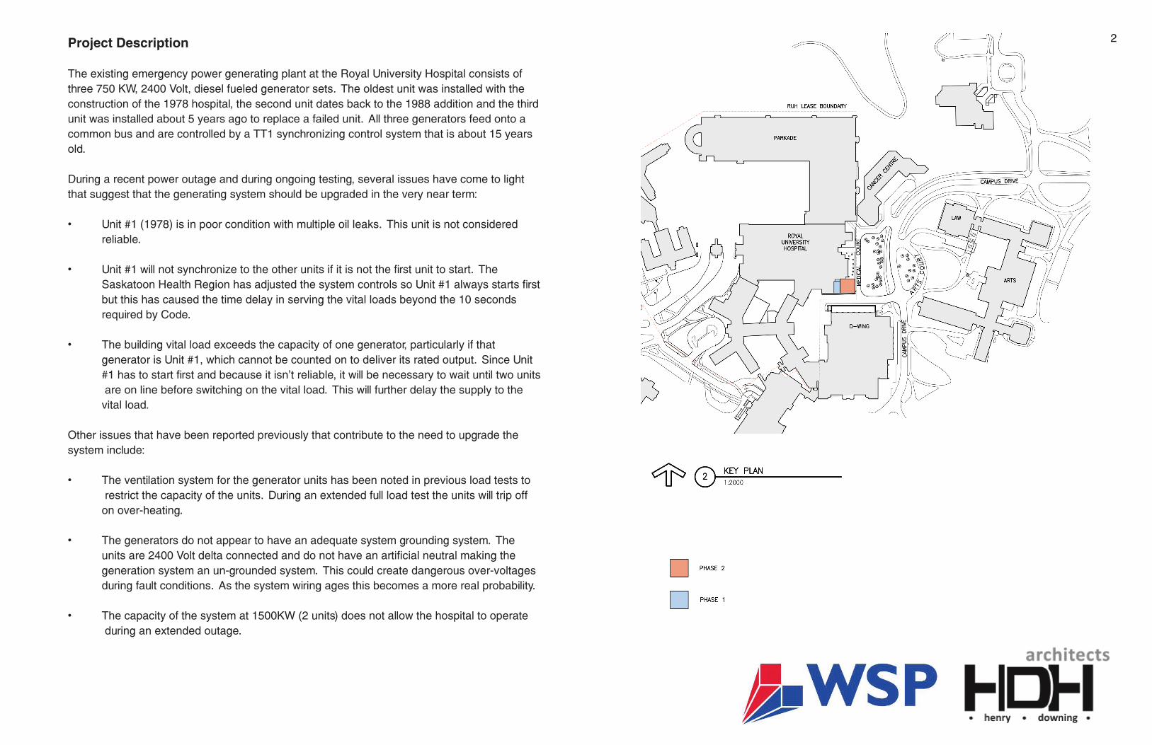
Project Description The existing emergency power generating plant at the Royal University Hospital consists of three 750 KW, 2400 Volt, diesel fueled generator sets. The oldest unit was installed with the construction of the 1978 hospital, the second unit dates back to the 1988 addition and the third unit was installed about 5 years ago to replace a failed unit. All three generators feed onto a common bus and are controlled by a TT1 synchronizing control system that is about 15 years old. During a recent power outage and during ongoing testing, several issues have come to light that suggest that the generating system should be upgraded in the very near term: • Unit #1 (1978) is in poor condition with multiple oil leaks. This unit is not considered reliable. • Unit #1 will not synchronize to the other units if it is not the first unit to start. The Saskatoon Health Region has adjusted the system controls so Unit #1 always starts first but this has caused the time delay in serving the vital loads beyond the 10 seconds required by Code. • The building vital load exceeds the capacity of one generator, particularly if that generator is Unit #1, which cannot be counted on to deliver its rated output. Since Unit #1 has to start first and because it isn’t reliable, it will be necessary to wait until two units are on line before switching on the vital load. This will further delay the supply to the vital load. Other issues that have been reported previously that contribute to the need to upgrade the system include: • The ventilation system for the generator units has been noted in previous load tests to restrict the capacity of the units. During an extended full load test the units will trip off on over-heating. • The generators do not appear to have an adequate system grounding system. The units are 2400 Volt delta connected and do not have an artificial neutral making the generation system an un-grounded system. This could create dangerous over-voltages during fault conditions. As the system wiring ages this becomes a more real probability. • The capacity of the system at 1500KW (2 units) does not allow the hospital to operate during an extended outage. 2
Transcript of Project Description - Meewasin Valley Authoritymeewasin.com/assets/upload/resources... · Project...
Project Description
The existing emergency power generating plant at the Royal University Hospital consists of three 750 KW, 2400 Volt, diesel fueled generator sets. The oldest unit was installed with the construction of the 1978 hospital, the second unit dates back to the 1988 addition and the third unit was installed about 5 years ago to replace a failed unit. All three generators feed onto a common bus and are controlled by a TT1 synchronizing control system that is about 15 years old.
During a recent power outage and during ongoing testing, several issues have come to light that suggest that the generating system should be upgraded in the very near term:
• Unit#1(1978)isinpoorconditionwithmultipleoilleaks.Thisunitisnotconsidered reliable.
• Unit#1willnotsynchronizetotheotherunitsifitisnotthefirstunittostart.The SaskatoonHealthRegionhasadjustedthesystemcontrolssoUnit#1alwaysstartsfirst but this has caused the time delay in serving the vital loads beyond the 10 seconds required by Code.
• Thebuildingvitalloadexceedsthecapacityofonegenerator,particularlyifthat generatorisUnit#1,whichcannotbecountedontodeliveritsratedoutput.SinceUnit #1hastostartfirstandbecauseitisn’treliable,itwillbenecessarytowaituntiltwounits are on line before switching on the vital load. This will further delay the supply to the vital load.
Other issues that have been reported previously that contribute to the need to upgrade the system include:
• Theventilationsystemforthegeneratorunitshasbeennotedinpreviousloadteststo restrict the capacity of the units. During an extended full load test the units will trip off on over-heating.
• Thegeneratorsdonotappeartohaveanadequatesystemgroundingsystem.The units are 2400 Volt delta connected and do not have an artificial neutral making the generation system an un-grounded system. This could create dangerous over-voltages during fault conditions. As the system wiring ages this becomes a more real probability.
• Thecapacityofthesystemat1500KW(2units)doesnotallowthehospitaltooperate during an extended outage.
CONTENTS
PROJECT DESCRIPTION 2CONSTRUCTION SEQUENCING PLAN 4 RENDERING 1 5RENDERING 2 6BUILDING CODE ANALYSIS 7 DRAFT SPECIFICATIONS 8DESIGN INTENT 10
1 2
A project is currently underway to replace the existing main transfer switch with a new unit complete with full by-pass capability. The project also includes the replacement of the main 25 KV service switchgear. The foundations for the switchgear have been sized to accommodate the construction of a new generating plant on a mezzanine above the service substation.
Replacement of the hospital generating system cannot be done on a unit-by-unit basis. This results in too many outages to the hospital which creates high levels of risk to the hospital and the patients.
A complete replacement allows the new equipment to be fully installed and tested before be-ing placed into service with a short planned outage during changeover from old to new. The new system will be sized to accommodate additional loads so RUH is able to operate through an extended power outage situation.
The location proposed for the construction of the new generator plant was chosen for the fol-lowing reasons:
• Closeproximitytotheexistingmainelectricalroomandthepointofconnectionofthe generator power.
• BuildingabovetheexistingelectricalsubstationcausestheleastimpacttotheRUH building and its operation.
• ThereisnoavailablebuildinglandwithintheRUHlandleasearea.
The proposed site does create some environmental and aesthetics issues, which we are ad-dressing as follows:
• Thenewgeneratorplantwillcreatemorenoisethantheexistinggenerators.Thisis being mitigated by the installation of silencers on the ventilation air intake and discharge system, by the installation of acoustic material on the building interior and by the installation of critical grade mufflers.
• Thenewgeneratorswillbesubstantiallylargerthantheexistinggeneratorswitha resultant increased engine exhaust volume. The generator units specified will be equipped with Tier 4i emission controls, which is the highest level currently available. Our specialist consultant, RWDI, advises that these emission control systems will result in zero increase in total exhaust odour and a reduction in the total exhaust pollutants.
• Becausetheexistinggeneratorsoccasionallycauseodourproblemsfortheadjacent buildings and considering that the new generators will not improve the odour emissions, we are proposing the construction of an exhaust stack to a level above the RUH roof. Wind tunnel testing indicates that this measure will reduce the probability of odour detection in the adjacent buildings to approximately 5% which is a vast improvement over the current probability of about 50%. • TheexistingdieselfuelstoragetankislocatedundergroundneartheRUHloadingdock. This tank will not be large enough to service the new plant. We are proposing the installation of above ground, double-walled tanks that will be incorporated into the plant building and will not be visible. The tank room will include a concrete spill containment basin. The existing underground fuel tank will be removed.
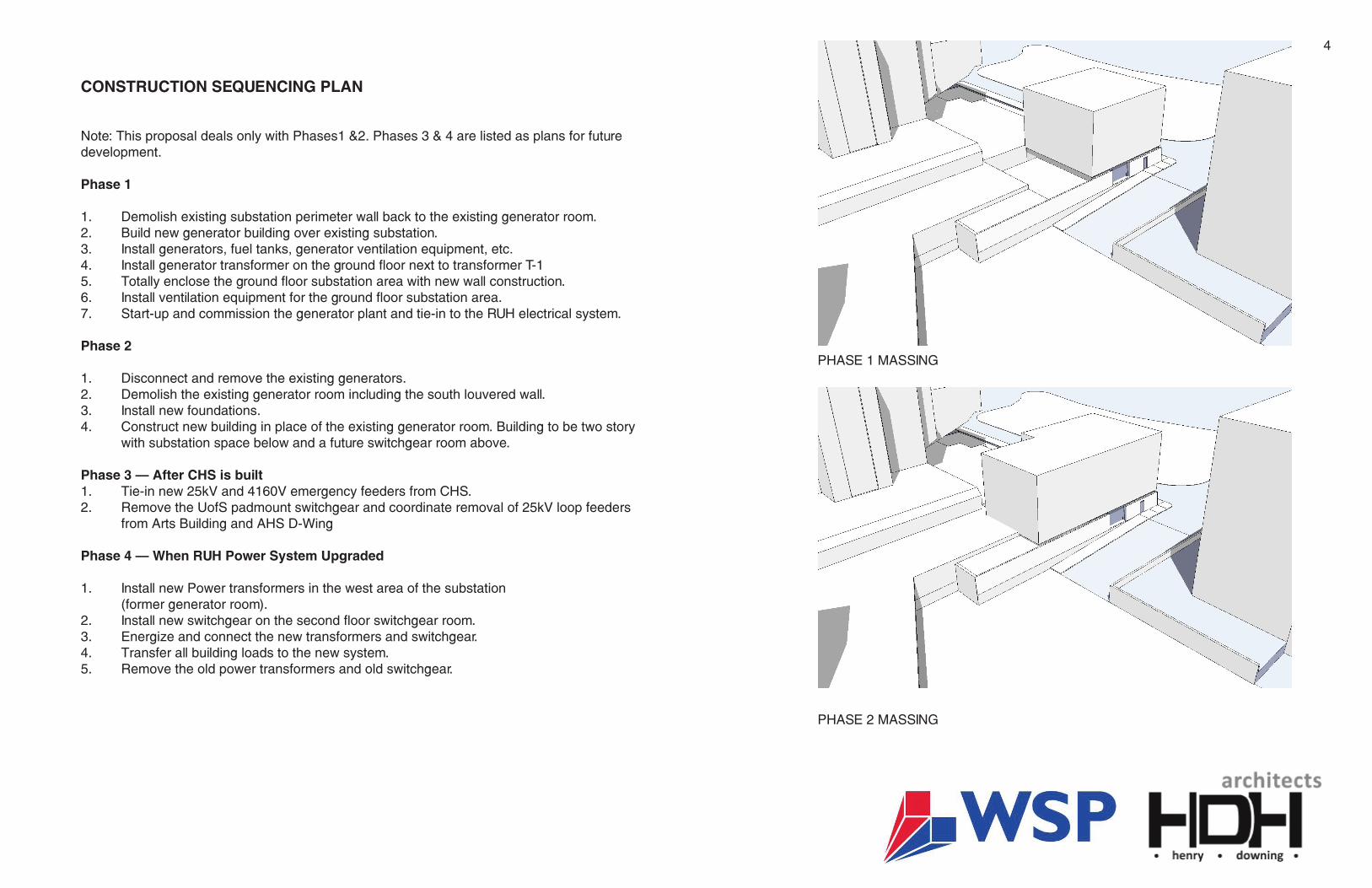
• ThegeneratorplantbuildingwillbeprovidedwithArchitecturaltreatmentsto complement the existing RUH design.
Construction of the new generator plant above the existing electrical substation also involves a number of engineering and construction challenges, including the following:
• Installationofpilefoundationsinthesubstationareaisdifficultbecausetheexisting electrical equipment must remain operational during the construction. To improve the situation, we are proposing to remove the existing concrete wall around the substation, allowing better access for a piling rig. As mentioned before, we have already installed some foundations as part of the electrical switchgear upgrade.
• Thegeneratorplantbuildingwillbebuiltintwophases;phase1tobebuiltabovethe substation and housing the generators and associated switchgear, and phase 2 to be builtabovetheexistinggeneratorroom(tobedemolishedafterphase1iscomplete) and housing existing and future transformers and future switchgear. The phasing is required to keep the existing generators operational until the new plant is ready for use.
• Theexhauststackswillbesupportedbythenewgeneratorplantbuildingstructure.It is not considered feasible to off-set the exhaust stacks and run them up the side of the RUH building. As a result, we are designing a truss tower to support the exhaust stacks.
3
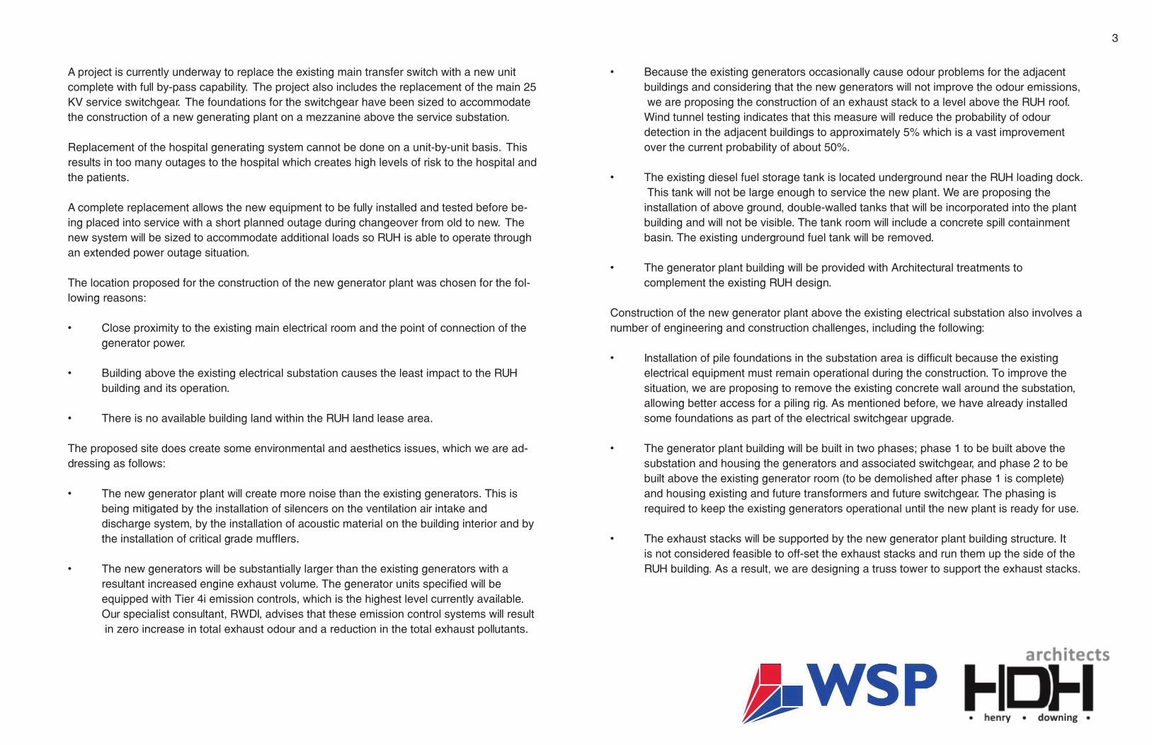
PHASE 1 MASSING
PHASE 2 MASSING
CONSTRUCTION SEQUENCING PLAN
Note: This proposal deals only with Phases1 &2. Phases 3 & 4 are listed as plans for future development.
Phase 1
1. Demolish existing substation perimeter wall back to the existing generator room.2. Build new generator building over existing substation.3. Install generators, fuel tanks, generator ventilation equipment, etc.4. Install generator transformer on the ground floor next to transformer T-15. Totally enclose the ground floor substation area with new wall construction.6. Install ventilation equipment for the ground floor substation area.7. Start-up and commission the generator plant and tie-in to the RUH electrical system.
Phase 2
1. Disconnect and remove the existing generators.2. Demolish the existing generator room including the south louvered wall.3. Install new foundations.4. Construct new building in place of the existing generator room. Building to be two story with substation space below and a future switchgear room above.
Phase 3 – After CHS is built1. Tie-in new 25kV and 4160V emergency feeders from CHS.2. Remove the UofS padmount switchgear and coordinate removal of 25kV loop feeders from Arts Building and AHS D-Wing
Phase 4 – When RUH Power System Upgraded
1. Install new Power transformers in the west area of the substation (formergeneratorroom).2. Install new switchgear on the second floor switchgear room.3. Energize and connect the new transformers and switchgear.4. Transfer all building loads to the new system.5. Remove the old power transformers and old switchgear.
3 4
VIEW FROM ACADEMIC HEALTH SCIENCES D-WING PATIO
5

VIEW FROM RUH LOADING AREA
5 6