project descriptioneisdocs.dsdip.qld.gov.au/Sunshine Coast Airport Expansion/EIS... · 4.7b:...
24
CONTENTS 4.1 Overview of the project..................................................... 75 4.2 The Project............................................................................ 75 4.2.1 New Runway 13/31 ................................................... 75 4.2.2 ATC tower and ARFFS station ............................. 76 4.2.3 Enabling infrastructure ............................................. 76 4.2.4 Waste management .................................................. 76 4.2.5 Employment ................................................................. 76 4.3 Design considerations ...................................................... 78 4.3.1 Preliminary design process.................................... 78 4.3.1.1 Master Plan Implementation Project ........ 78 4.3.1.2 Environmental Impact Statement............... 78 4.4 Existing infrastructure ....................................................... 78 4.4.1 Existing airport infrastructure ................................ 78 4.4.2 Existing external infrastructure.............................. 78 4.5 Existing environmental conditions ................................ 80 4.6 New runway 13/31 .............................................................. 80 4.6.1 Location.......................................................................... 80 4.6.2 Design standards for the new runway .............. 80 4.6.3 Design aircraft and traffic........................................ 80 4.6.4 Geometric design....................................................... 82 4.6.5 Runway length............................................................. 82 4.6.6 Runway width .............................................................. 82 4.6.7 Taxiways ......................................................................... 83 4.6.8 Aprons............................................................................. 84 4.6.9 Existing 18/36 Runway ............................................ 84 4.6.10 Existing 12/30 Runway ............................................ 84 4.6.11 Aviation operations .................................................... 84 4.7 Airfield pavements .............................................................. 84 4.7.1 Aircraft and operational considerations............ 84 4.7.2 Geotechnical considerations................................. 84 4.7.3 Pavement types .......................................................... 84 4.7.4 Adopted pavement thickness ............................... 85 4.8 Subsurface and geotechnical conditions.................... 85 4.8.1 Geotechnical investigations ................................... 85 4.8.2 Ground conditions ..................................................... 86 4.8.3 Adopted geotechnical design ............................... 86 4.8.4 Fill staging ......................................................................87 4.8.5 Instrumentation ............................................................87 4.9 Airport drainage .................................................................. 88 4.9.1 Major drainage ............................................................ 88 4.9.2 Minor drainage ............................................................ 88 4.9.3 Water quality ................................................................ 88 4.10 Extension of Airport Drive................................................ 88 4.11 Perimeter roads .................................................................. 88 4.12 Security fencing .................................................................. 88 4.13 Airfield lighting ......................................................................91 4.13.1 Approach lighting........................................................ 91 4.13.2 Ground lighting system ............................................ 91 4.13.3 Design considerations.............................................. 94 4.14 ATC tower and ARFFS station ........................................ 94 4.15 Services ................................................................................. 94 4.15.1 Existing services ......................................................... 94 4.15.2 Relocations ................................................................... 96 4.15.3 New services ................................................................ 96 4.16 Landscaping......................................................................... 96 4.16.1 Existing landscape features ................................... 96 A4-74 SUNSHINE COAST AIRPORT EXPANSION PROJECT A4 BACKGROUND TO THE PROJECT PROJECT DESCRIPTION
Transcript of project descriptioneisdocs.dsdip.qld.gov.au/Sunshine Coast Airport Expansion/EIS... · 4.7b:...

Contents
4.1 Overview of the project ..................................................... 75
4.2 The Project ............................................................................ 75 4.2.1 New Runway 13/31 ................................................... 75 4.2.2 ATC tower and ARFFS station ............................. 76 4.2.3 Enabling infrastructure ............................................. 76 4.2.4 Waste management .................................................. 76 4.2.5 Employment ................................................................. 76
4.3 Design considerations ...................................................... 78 4.3.1 Preliminary design process .................................... 78 4.3.1.1 Master Plan Implementation Project ........78 4.3.1.2 Environmental Impact Statement ...............78
4.4 Existing infrastructure ....................................................... 78 4.4.1 Existing airport infrastructure ................................ 78 4.4.2 Existing external infrastructure .............................. 78
4.5 Existing environmental conditions ................................ 80
4.6 New runway 13/31 .............................................................. 80 4.6.1 Location .......................................................................... 80 4.6.2 Design standards for the new runway .............. 80 4.6.3 Design aircraft and traffic........................................ 80 4.6.4 Geometric design ....................................................... 82 4.6.5 Runway length............................................................. 82 4.6.6 Runway width .............................................................. 82 4.6.7 Taxiways ......................................................................... 83 4.6.8 Aprons............................................................................. 84 4.6.9 Existing 18/36 Runway ............................................ 84 4.6.10 Existing 12/30 Runway ............................................ 84 4.6.11 Aviation operations .................................................... 84
4.7 Airfield pavements .............................................................. 84 4.7.1 Aircraft and operational considerations ............ 84 4.7.2 Geotechnical considerations ................................. 84 4.7.3 Pavement types .......................................................... 84 4.7.4 Adopted pavement thickness ............................... 85
4.8 Subsurface and geotechnical conditions .................... 85 4.8.1 Geotechnical investigations ................................... 85 4.8.2 Ground conditions ..................................................... 86 4.8.3 Adopted geotechnical design ............................... 86 4.8.4 Fill staging ......................................................................87 4.8.5 Instrumentation ............................................................87
4.9 Airport drainage .................................................................. 88 4.9.1 Major drainage ............................................................ 88 4.9.2 Minor drainage ............................................................ 88 4.9.3 Water quality ................................................................ 88
4.10 Extension of Airport Drive ................................................ 88
4.11 Perimeter roads .................................................................. 88
4.12 Security fencing .................................................................. 88
4.13 Airfield lighting ......................................................................91 4.13.1 Approach lighting ........................................................91 4.13.2 Ground lighting system ............................................91 4.13.3 Design considerations.............................................. 94
4.14 ATc tower and ArffS station ........................................ 94
4.15 Services ................................................................................. 94 4.15.1 Existing services ......................................................... 94 4.15.2 Relocations ................................................................... 96 4.15.3 New services ................................................................ 96
4.16 Landscaping ......................................................................... 96 4.16.1 Existing landscape features ................................... 96
A4-74 SUNSHINE COAST AIRPORT EXPANSION PROJECT
A4 background to thE ProjEct
project description

FIGURes
4.1a: Indicative proposed development ...............................................77 4.4a: Existing development at Sca ........................................................794.4b: development and infrastructure external to Sca ...............814.6a: b737 (code c aircraft) – currently operates at Sca ........824.6b: b787 (code E aircraft) – could operate from the new
runway at Sca ......................................................................................824.6c: declared distances for runway 13 .............................................834.6d: declared distances for runway 31 .............................................834.6e: components of the runway strip for a non-precision
approach runway .................................................................................834.7a: Indicative runway and taxiway flexible
pavement profile ...................................................................................854.7b: Indicative apron rigid pavement profile ....................................854.8a: Indicative surcharge area .................................................................874.9a: Indicative drainage layout for the Project ................................894.9b: Indicative catchment of the northern and
southern perimeter drains ...............................................................904.10a: Indicative location of airport drive extension ........................914.11a: Indicative alignment of the existing and proposed
airside perimeter fence and road ................................................924.13a: Indicative proposed airfield lighting for rWY 13/31 ...........934.15a: Existing utilities locations .................................................................954.15b: Indicative proposed utilities locations ........................................97
tABLes
4.6a: declared distances for rWY 13/31 ............................................824.7a: Indicative depth of pavement for the new runway .............85
4.1 oveRvIew oF the PRojeCt
the key elements of the Project include a new runway and aprons and expansion of the existing terminal and other support services at Sunshine coast airport.
the preferred option of building a new runway, rather than widening the existing runway, was chosen because it allows for full compliance with the Manual of Standards Part 139–aerodromes (MoS 139) and provides opportunities to accommodate larger aircraft and more aircraft movements. this will allow Sca to service more distant destinations and help Sca achieve its objectives of supporting the regional economy. alternative development options that were considered are discussed in chapter a3 –options and alternatives.
the Project is shown in figure 4.1a.
the following sections provide an overview of the Project.
4.2 the PRojeCt
4.2.1 new Runway 13/31
the new runway will be a 45 m wide and 2,450 m long code E runway, capable of servicing code E aircraft such as the a330 and boeing 777 and 787. It will have an orientation of 128°/308° magnetic, giving the runway its 13/31 designation. runway 13/31 (rWY 13/31) will be serviced by two end taxiway loops, as shown in the layout in figure 4.1a. the end taxiway loops allow for increased aircraft movements on the runway, as an aircraft can be waiting on the taxiway while another aircraft is using the runway to land or take-off.
the new runway will be served by the existing terminal. to accommodate larger aircraft, the apron at the existing terminal will be extended to accommodate code E aircraft.
once complete, rWY 13/31 is expected to be used by all regular Passenger transport (rPt) aircraft and 90 per cent of general aviation (ga). the ‘fly neighbourly’ policy, which voluntarily limits night time flights, will remain in place. While the new rWY 13/31 is designed to cater for larger aircraft, light aircraft and helicopters will continue to operate from the airport. Further information on planned aviation operations is provided in chapter a2 – need for the Project.
A4-75environmental impact statement

rWY 13/31 will be located in the flood plain of the Maroochy river, east of the Sunshine Motorway. to reduce potential flood impacts, a drainage scheme has been designed for the runway, as shown in figure 4.1a and is described in Section 4.10. a northern perimeter drain will be developed to direct overland flood flow from the north of the runway north-west into Marcoola drain.
a western perimeter drain will be constructed to connect the northern perimeter drain to the existing southern perimeter drain to improve the conveyance of floodwater around the end of the runway. Stormwater runoff from the proposed runway itself will be directed into the perimeter drains, which will discharge into a number of existing drainage lines that cross beneath the Sunshine Motorway and flow west to the Maroochy river.
rWY 13/31 has been designed to have immunity from a 100-year average recurrence interval (arI) flood event in combination with a 2100 sea level rise scenario of 0.8 m. to provide this immunity, approximately 1.1 M m3 of fill is required to build up the runway platform. the fill material will be dredged from Spitfire realignment channel in Moreton bay using a trailing Suction hopper dredger (tShd). Sand will be pumped from the tShd at an offshore location near Marcoola to the construction site. the dredging process is described in chapter a5 – Project construction.
construction of rWY 13/31 is expected to take a total of up to four years, with some activities occurring concurrently, as follows:
y approximately 18 months for excavation of drains, services realignments, development of construction access roads and dredging, delivery and placement of sand
y up to 12 months consolidation period at the north-west end of the runway, during which time profiling and pavement construction at the south-eastern end of rWY 13/31 would commence
y approximately 18 months for trimming the surcharge and placing it to form the final earthworks platform, construction of airfield pavements, and installation of airfield lighting and navigation aids.
4.2.2 AtC tower and ARFFs station
a new facility will be developed to co-locate the air traffic control (atc) tower and aviation rescue and Fire Fighting Service (arFFS); it will be developed to be operational in time for the opening of the new runway.
airport drive will be extended to the atc tower/arFFS station to provide access for construction and operation of the facility. the road will be single lane each way.
a community viewing platform will be established adjacent to the atc tower.
4.2.3 enabling infrastructure
to enable and support the development of rWY 13/31, the following will be required:
y relocation of the VhF omnidirectional radio range (Vor) from its current location to an area near the north-west end of rWY 13/31
y relocation of the existing helipads to a location near the relocated Vor
y construction of a new airside perimeter fence to ensure the security of the new runway, and an airside perimeter road to facilitate access around the runway for maintenance and emergency response.
these facilities are discussed further in subsequent sections.
4.2.4 waste management
the Project is expected to generate an incremental increase in operational waste as the passenger numbers at the airport increase. typical wastes produced at the airport include quarantine waste from international flights, food and packaging waste from the terminal and domestic flights, office waste from administrative functions and waste from aircraft maintenance activities. the existing waste management facilities and arrangements will be upgraded and expanded in response to demand.
Waste generation rates and management during construction are discussed in chapter a5 – Project construction.
4.2.5 employment
as discussed in chapter a2, employment is expected to be generated from development of the Project both directly and indirectly. It is estimated that in 2020, approximately 165 direct and 78 flow-on full-time equivalent (FtE) positions will be generated. by 2040, this is expected to increase to 1,538 direct and 693 flow-on FtE positions.
A4-76
background to the project
project descriptionA4
SunShIne coaSt aIrport eXpanSIon project

A4-77environmental impact statement
Figure 4.1a: Indicative proposed development
Relo
cate
d VH
F om
nidi
rect
iona
l rad
io
rang
e (V
OR) n
avig
atio
n ai
d
Com
mun
ity v
iew
ing
plat
form
Airs
ide
perim
eter
fe
nce
and
road
Runw
ay d
rain
Taxi
way
loop
s
Relo
cate
d he
lipad
s
Nort
hern
per
imet
er d
rain
New
Run
way
13/
31
Airs
ide
perim
eter
fenc
e an
d ac
cess
trac
k
Wes
tern
per
imet
er
drai
n
Sout
hern
per
imet
er d
rain
New
Air
Traf
fic C
ontr
ol (A
TC) T
ower
and
Av
iatio
n Re
scue
and
Fire
Fig
htin
g Se
rvic
e (A
RFFS
) Sta
tion
Airp
ort D
rive
exte
nsio
n Apro
n ex
pans
ion
Upgr
ades
to th
e ex
istin
g te
rmin
al

4.3 DesIGn ConsIDeRAtIons
4.3.1 Preliminary design process
the preliminary design for the Project built on work completed as part of the Initial advice Statement (IaS) and Environmental Protection and Biodiversity Conservation Act 1998 (EPbc act) referral process in 2010. the preliminary design provides the basis for the assessment of impacts presented in this EIS.
4.3.1.1 Master Plan Implementation Project
a preliminary design for the new runway was developed during the Master Plan Implementation Project (2010) based on a review of the site constraints and operational requirements for the new runway. constraints were identified based on information held by Sunshine coast council (Scc) and available in public databases at the time of preliminary design (before detailed ecological and other environmental studies were undertaken for the EIS). a gap analysis was undertaken to determine where there was insufficient information available to inform the preliminary design and determine which additional investigations and studies would be required.
Field investigations undertaken to inform the preliminary design included geotechnical, acid sulphate soil, field survey, and preliminary ecological survey. Preliminary flood modelling for the Maroochy river near the airport and the existing drainage on-airport was performed to determine the existing flood regime and flood heights for a range of flood events. the results of the geotechnical investigations were assessed to determine underlying ground conditions and ground treatment requirements.
a number of design options were investigated to understand and where possible, quantify the impacts of some design elements on the environment, airport security, aviation operations and constructability. given the topographical constraints of the site, particularly the presence of Mt coolum to the north and mountain ranges to the north-west, the number of runway options available to investigate was limited.
chapter a5 – Project construction provides a discussion of the alternative development options that were considered. the preferred option of building a new rWY 13/31 was carried forward into the EIS.
4.3.1.2 Environmental Impact Statement
the design of the new runway was refined during preparation of the EIS as more information around site and project constraints became available.
detailed investigations revealed several environmental, geotechnical and construction issues that carry both cost and timing implications for the new runway.
the terrain at the north-west end of rWY 13/31 comprises deep marine clays that would require considerable geotechnical improvements to be suitable for a new runway.
For the original proposal identified in the Master Plan and addressed in the IaS, in the order of 500,000 m3 of additional surcharge fill would be required to be in place for up to 4 years to compress the soft soils beneath the runway – this would add considerable cost and time to the construction of the new runway. In addition, flood modelling of the runway platform indicated that considerable infrastructure would be required to mitigate the flood impacts.
consequently, the scope of the Project was revised from the original considered in the Master Plan Implementation Project to address these issues. the key change to the scope was the location of the runway thresholds (the functional end of the runway), which were moved 310 m to the south-east. this change avoids much of the soft compressible soils at the north-west end, and also reduces the potential flood impacts associated with the Project.
the proposed design for the Project is as described in Section 4.1.
4.4 exIstInG InFRAstRUCtURe
4.4.1 existing airport infrastructure
the existing development at Sca is entirely aviation related. key elements within the existing Sca include:
y runway 18/36 (the current main runway)
y runway 12/30 (the cross runway)
y the terminal building, baggage handling and apron
y Southern ga facilities and apron
y the western ga facilities and apron
y Fuel storage facility
y the terminal car park and
y a commercial area for aviation related business.
additionally, Sca is currently developing a Sunshine coast aerospace Precinct at the southern end of rWY 18/36, which is being undertaken separately to the Project.
figure 4.4a shows the locations of existing airport features.
4.4.2 existing external infrastructure
the current main runway, rWY 18/36, was opened in 1961, and urban development has occurred in the intervening time to the north, south and east of the airport. In particular, urban development has occurred at Marcoola, Mudjimba and Pacific Paradise and an industrial estate is located to the west of the airport.
the Sunshine Motorway runs in a north-south direction to the west of the proposed runway. an interchange is located west of the airport, which connects to david Low Way at the intersection of airport drive. david Low Way extends around the airport to Marcoola in the north. Finland road, which is planned to be used as a construction access road, connects
A4-78
background to the project
project descriptionA4
SunShIne coaSt aIrport eXpanSIon project

A4-79environmental impact statement
Figure 4.4a: Existing development at SCA
19 July 2014 \\aubne1fp003\projects\projects\60248594\6. draft docs\6.1 reports\rescope reports\001_project description\project description images rev f_20140619.docx 2 of 13
Figure 4.5a: Existing development at SCA
Runway 18/36
Terminal & apron
Runway 12/30
Former cane farmland
Mt Coolum National Park
General aviation
Mt Coolum National Park
Commercial area
Car park
Sunshine Coast Aerospace precinct (currently under construction)
Helipads
Non-directional beacon (NDB)
VHF omnidirectional radio range
Fuel farm
ARFFS station
ATC tower

to david Low Way west of the Motorway, and passes over the Motorway west of the proposed rWY 13/31.
two sections of the Mt coolum national Park are situated to the north and south of the proposed runway.
Existing infrastructure and features external to the airport are shown in figure 4.4b.
4.5 exIstInG envIRonmentAL ConDItIons
the site of the proposed development has a generally flat topography with a gentle downwards slope to the south and west towards the Maroochy river. approximately 65 per cent of the area was previously cleared for cane farming, and a number of drainage channels associated with the site’s previous use are present within the development footprint.
areas within the development footprint that were not previously cleared retain remnant vegetation characterised by the low-lying and seasonally moist conditions and include Melaleuca forest and closed heath on sand plains and a small area of open forest.
Sections of Mt coolum national Park are located north and south of the proposed development area.
ground Parrots (Pezoporus wallicus wallicus), listed as Vulnerable under the Nature Conservation Act 1992 (nc act), are known to occur near the existing runway, and drainage lines within the area provide habitat for wallum frogs including the Wallum Froglet (Crinia tinnula) and Wallum rocketfrog (Litoria freycineti), both listed as Vulnerable under the nc act. Mt Emu Sheoak (Allocasuarina emuina), listed as Endangered under the EPbc act, has been identified within the site.
the surrounding mountains and ranges have a strong influence on the design of the runway. Mt coolum is located approximately 4 km north of the airport, and Mt ninderry is located 8.6 km north-west of the runway. the preliminary design of the Project was developed to accommodate these topographical features while reducing environmental impacts where possible.
4.6 new RUnwAy 13/31
4.6.1 Location
rWY 13/31 will intersect the existing rWY 18/36 slightly north of the current connection to the cross runway (rWY 12/30). the alignment of rWY 13/31 was chosen to avoid topographical constraints including Mt coolum and Mt ninderry. the location of the runway within the site was influenced by the following factors:
y achieving the runway length required to meet target destinations in asia and the length required for code E aircraft
y reducing the number of houses within the Public Safety area at the south-east end of the runway (the Public Safety area is a requirement of the State Planning Policy)
y reducing the number of residents affected by aircraft noise
y avoiding poor geotechnical conditions immediately east of the Sunshine Motorway at the north-west end of the runway
y Providing adequate flood conveyance capacity between the end of the runway and the Sunshine Motorway to reduce potential flood impacts.
4.6.2 Design standards for the new runway
the International Standards and recommended practices for runway design are formalised in annex 14 of the convention on International civil aviation, adopted by the International civil aviation organisation (Icao). the national aviation standards and advisory publications are administered in australia by the civil aviation Safety authority (caSa) under the Civil Aviation Act 1988, the civil aviation regulations 1988 (car 1988) and the civil aviation Safety regulations 1998 (caSr 1998).
Many parts of the caSr 1998 are supported by a Manual of Standards (MoS), which contains detailed technical material, such as technical specifications or standards. the relevant parts of MoS are:
y MoS Part 139-aerodromes – the requirements for aerodromes used in air transport operations are prescribed in the caSa policy manual
y MoS Part 172-air traffic Services – the requirements and standards for compliance by an air traffic service provider, including the facilities and equipment required.
the planning and design standards for the geometry of the new runway are generally the requirements and recommendations set out in Icao annex 14 and Part 139 caSa MoS.
advisory circulars are published by caSa, and are intended to provide recommendations and guidance to illustrate a means of complying with the regulations.
4.6.3 Design aircraft and traffic
the Icao has a code system, which defines the runway length and width requirements for an airport to service certain aircraft types. the current main runway is a code 3c runway, with code 4c aircraft operating under a dispensation from caSa. rWY 13/31 and associated taxiways and aprons have been designed based on an aerodrome reference code 4E. this will enable the airport to service larger and new generation aircraft such as the airbus a330-300 and boeing b787-8 a350XWb and b777- 300. the primary difference between code c (figure 4.6a) and code E (figure 4.6b) aircraft is their size and passenger capacity; as an example, code c aircraft have a maximum wingspan of 36 m whereas code E aircraft
A4-80
background to the project
project descriptionA4
SunShIne coaSt aIrport eXpanSIon project

A4-81environmental impact statement
19 July 2014 \\aubne1fp003\projects\projects\60248594\6. draft docs\6.1 reports\rescope reports\001_project description\project description images rev f_20140619.docx 3 of 13
Figure 4.5b: Development and infrastructure external to SCA
David Low Way
Finland Road overpass
Marcoola
Sunshine Motorway
MT COOLUM NATIONAL PARK
Industrial estate
MT COOLUM NATIONAL PARK
Sewage treatment plant
Mudjimba
Pacific Paradise
Sunshine Motorway
interchange
Marcoola drain
Marcoola Finland Road
Cane underpass
Maroochy River
Keith Royal Park
Figure 4.4b: Development and infrastructure external to SCA

have a wingspan of up to 65 m. Similarly, the passenger capacity of code 4E aircraft is greater than code 3c, for example, the code 4E b787 can carry up to 330 passengers, whereas the code 3c b737 can carry up to 215 passengers.
a conservative ‘design’ aircraft of 65 m wingspan and 76 m length has been adopted for planning purposes for the runway, taxiways and aprons. these dimensions accommodate the largest code 4E aircraft, the airbus a340- 600, with a wingspan of 63.7 m and length of 75.3 m.
to inform the noise modelling, an assumed combination and number of aircraft types from ga up to code 4E using the airport was adopted. refer to chapter d3 – aircraft noise for further details.
4.6.4 Geometric design
MoS 139 sets out the regulatory regime of aerodromes used by aeroplanes conducting air transport operations – this includes design requirements for runways, taxiways, aprons, other aerodrome infrastructure and obstacle clearance. rWY 13/31 and associated facilities have been designed to comply with MoS 139 requirements for Icao code 4E aerodromes.
4.6.5 Runway length
the runway length of both the existing rWY 18/36 and the proposed rWY 13/31 is constrained by existing development surrounding the airport.
rWY 13/31 has been designed to reduce the amount of existing development included within the associated runway Public Safety areas. this resulted in the rWY 31 end being located approximately 180 m north-west of the intersection with the existing rWY 18/36. the 180 m of pavement between the rWY 31 threshold and rWY 18/36 intersection may be used for additional take off length for rWY 31 departures (refer figure 4.6d). the runway includes runway End Safety areas (rESa) at each end that extend 240 m beyond the end of the runway strip (refer figure 4.6e).
Preliminary declared distances for the proposed runway are summarised in Table 4.6a.
figure 4.6c and figure 4.6d illustrate the calculation of rWY 13 and 31 operational lengths respectively. as the figures show, the ‘length’ of rWY 13/31 depends on which ‘declared distance’ is used as the reference.
Table 4.6a: Declared distances for RWY 13/31
DistanceRwy 13
(nw to se)Rwy 31
(se to nw)
take-off run available (tora) 2,450 m 2,630 m
accelerate/Stop distance available (aSda) 2,450 m 2,630 m
Landing distance available (Lda) 2,450 m 2,450 m
the proposed runway take-off lengths of between 2,450 m and 2,630 m will facilitate unrestricted operations by the new generation b787 aircraft; however, some payload/range restrictions will apply to a330/b777 aircraft.
4.6.6 Runway width
rWY 13/31 will be 45 m wide in accordance with MoS 139 requirements for code 4E runways. the total area required for the runway includes the pavement, shoulders and runway strip, as required under MoS 139 (refer figure 4.6e).
the runway shoulders will extend 7.5 m from the edges of the runway pavement (refer figure 4.7a). the runway shoulders will be flush with the runway and slope downwards away from the runway. they will be resistant to aeroplane engine blast erosion and capable of supporting an aeroplane that has run off the runway without causing structural damage to the aircraft.
the runway strip is a clear area provided on each side of the runway to create a buffer zone in the event of an aircraft leaving the runway. the runway strip consists of two components: the graded runway strip adjacent to the runway shoulders, and the fly-over area outside the graded runway strip. the runway strip will be grassed, and drainage channels will be located outside the graded runway strip to ensure that standing water doesn’t attract birds next to the runway.
Figure 4.6a: B737 (Code C aircraft) – currently operates at SCA (source: jetphotos.net)
Figure 4.6b: B787 (Code E aircraft) – could operate from the new runway at SCA
A4-82
background to the project
project descriptionA4
SunShIne coaSt aIrport eXpanSIon project

4.6.7 taxiways
two end taxiway loops will be developed to allow aircraft access between the runway and the terminal and provide additional runway capacity. the taxiway configuration will have a considerable effect on the capacity of the runway, as the ability for aircraft to exit the runway quickly decreases the time between consecutive aircraft movements.
the geometry of the taxiways is influenced by the wheel tracks of the design aircraft and the clearance requirements of MoS 139. the minimum width for straight sections of code E taxiways is 23 m, and the minimum distance between the aircraft’s outer wheels and the edge of the taxiway pavement is 4.5 m. the wheel tracks of each aircraft likely to use the taxiways will be modelled to ensure the 4.5 m buffer is maintained throughout the taxiway system. this will be undertaken in later stages of the design.
19 July 2014 \\aubne1fp003\projects\projects\60248594\6. draft docs\6.1 reports\rescope reports\001_project description\project description images rev f_20140619.docx 4 of 13
Figure 4.7c: declared distances for Runway 13
Figure 4.7d: Declared distances for Runway 31
Figure 4.7e: Components of the runway strip for a non-precision approach runway
2,450 m
TORA
ASDA
LDA 2,450 m
2,450 m
2,450 m
RWY 13
RWY STRIP
RESA
13
31
RESA
180 m 2,450 m
TORA
ASDA
LDA 2,450 m
2,630 m
2,630 m
RWY 31
RWY STRIP
RESA
13
31
60 m
150 m 75 m RUNWAY
GRADED RUNWAY STRIP
FLYOVER AREA
19 July 2014 \\aubne1fp003\projects\projects\60248594\6. draft docs\6.1 reports\rescope reports\001_project description\project description images rev f_20140619.docx 4 of 13
Figure 4.7c: declared distances for Runway 13
Figure 4.7d: Declared distances for Runway 31
Figure 4.7e: Components of the runway strip for a non-precision approach runway
2,450 m
TORA
ASDA
LDA 2,450 m
2,450 m
2,450 m
RWY 13
RWY STRIP
RESA
13
31 RESA
180 m 2,450 m
TORA
ASDA
LDA 2,450 m
2,630 m
2,630 m
RWY 31
RWY STRIP
RESA
13
31
60 m
150 m 75 m RUNWAY
GRADED RUNWAY STRIP
FLYOVER AREA
Figure 4.6c: Declared distances for Runway 13
Figure 4.6d: Declared distances for Runway 31
Figure 4.6e: Components of the runway strip for a non-precision approach runway
A4-83environmental impact statement

as for the runway, MoS 139 requires that taxiways have shoulders and a taxiway strip. the taxiway shoulders will be 10.5 m wide, and be resistant to engine blast erosion. the taxiway strip consists of the inner taxiway strip, which overlaps the shoulder, and the overall taxiway strip, which extends 47.5 m either side of the taxiway centreline. the strip will be grassed and free of fixed objects other than navigational aids for aircraft and vehicle guidance.
4.6.8 Aprons
the apron at the existing terminal will be upgraded to accommodate the code 4E aircraft that will be able to use rWY 13/31. this will consist of expanding the paved area to accommodate the larger aircraft size, and strengthening the pavement to accommodate the increased aircraft weight.
4.6.9 existing 18/36 Runway
the existing rWY 18/36 will be maintained as an operational runway. It is not intended that rPt use 18/36 once 13/31 is operational. It is expected that a small percentage of ga (approximately 10 per cent) would continue to use 18/36. rWY 18/36 is constrained by existing land uses to the north and south, and there are no plans to extend the runway in the future.
4.6.10 existing 12/30 Runway
the development of the new runway requires the decommissioning and removal of the existing rWY 12/30, with the operations currently undertaken from this runway being moved to rWY 18/36 or rWY 13/31.
4.6.11 Aviation operations
It is an objective of the rWY 13/31 design that the existing rWY 18/36 can remain as an operational runway for light aircraft. the rWY 13/31 design achieves this by providing separation between the rWY 13/31 runway end and rWY 18/36, and also providing access to rWY 13/31 from the apron that doesn’t require aircraft to taxi along rWY 18/36.
4.7 AIRFIeLD PAvements
runways and taxiways require high strength pavements to support the high loads from aircraft movements. typically, aircraft carry the greatest load when taxiing to the runway for take-off: at this time, the aircraft is laden with passengers and cargo, as well as having full fuel tanks. conversely, arriving aircraft are lighter as they have consumed fuel during their flight.
the runway and taxiway pavements are designed in consideration of these operational characteristics, the types of aircraft, number of aircraft movements and any specific site requirements. typically, runways are designed with “flexible pavements” which consist of a gravel pavement with an asphalt surface, whereas taxiways have a combination of flexible and “rigid pavements” (concrete).
4.7.1 Aircraft and operational considerations
the pavement design is significantly dependant on the aircraft characteristics (wheel loadings and wheel configurations). FaarFIELd, which is the standard design software for airfield pavement thickness, was used to determine the preliminary pavement design.
the Federal aviation authority (Faa) advisory circulars and the aircraft database embedded in FaarFIELd include the majority of the heavy jet aircraft planned for use on rWY 13/31, with the exception of the a350, which is still in concept design stage. the a350 loading and configurations were assessed based on preliminary details and it was concluded the impact would be very similar to the b787 (which is the direct competitor aircraft for the a350). the aircraft characteristics for the preliminary pavement design were obtained from aircraft Manufacturers’ published data and the Faa aircraft characteristics database.
4.7.2 Geotechnical considerations
the site generally slopes down from the proposed south-eastern end of rWY 13/31 (which intersects the current airfield) at 3.95 m ahd, to the proposed north-western extent at less than 1 m ahd. the proposed north-western extent transitions into a low-lying “swampy” area.
the preliminary centreline design level for the runway and taxiways is 4.65 m ahd. this means that the entire runway will be filled, with depths varying from 0.8 m at the eastern end, up to approximately 4.0 m closer to the north-western end. the placement of compacted sand fill will provide a strong subgrade layer beneath the pavements.
Soft soils were found to underlie the north-western end of the proposed runway, and surcharge is proposed to improve consolidation in this area. Further details of the geotechnical conditions are provided in Section 4.9 and chapter b3 –geology, Soils and groundwater.
4.7.3 Pavement types
the new runway and associated taxiways, including shoulders, will have flexible pavements to provide the required smoothness for aircraft operations. the asphaltic seal will be a grooved, dense graded bituminous concrete.
apron pavements will be concrete slab surfaced pavement to accommodate the heavy static loads and the probability of fuel and oil drips from engines when parked and being serviced on the apron, which even if relatively small have a detrimental effect on asphaltic surfaces. asphaltic materials, being a viscoelastic material, are prone to rutting under heavy stationary wheel loads, which has adverse effects on ground service equipment traversing the aprons and results in increased annual maintenance expenditure.
A4-84
background to the project
project descriptionA4
SunShIne coaSt aIrport eXpanSIon project

4.7.4 Adopted pavement thickness
Flexible pavements consist of an asphalt seal over a pavement layer of fine crushed rock. the indicative depths of each pavement type are outlined in Table 4.7a.
the typical profile of a flexible runway or taxiway pavement and shoulder pavements is shown in figure 4.7a.
rigid pavements consist of a concrete slab over a cement stabilised base course. the base course primarily assists with load transfer across the slab joint lines and resists fine materials being brought to the surface through the flexure of the slabs at the joint lines. the rigid pavement profile proposed for the aprons is shown in figure 4.7b.
4.8 sUBsURFACe AnD GeoteChnICAL ConDItIons
the new runway site is located in a low-lying part of the Maroochy river floodplain. the majority of the site is unfilled, except where the new runway intercepts the existing rWY 18/36.
4.8.1 Geotechnical investigations
geotechnical investigations, as described in chapter b3 –geology, Soils and groundwater, have been undertaken to support the preliminary design of the new runway.
FINE CRUSHED ROCK
SUBGRADE SAND FILL EXISTING SURFACE
100 mm GROOVED DENSE GRADED BITUMINOUS CONRETE
RUNWAY or TAXIWAY SHOU
LDER
SHOU
LDER
200 mm CEMENT STABILISED BASE
410 mm PLAIN REINFORCED PORTLAND CEMENT CONCRETE
Table 4.7a: Indicative depth of pavement for the new runway
Area
Indicative Depth of Pavement
Fine Crushed Rock Asphalt seal
runway 210 mm 100 mm
taxiways 650 mm 100 mm
Shoulders, runway 210 mm 25 mm
Shoulders, taxiways 320 mm 25 mm
Figure 4.7a: Indicative runway and taxiway flexible pavement profile
Figure 4.7b: Indicative apron rigid pavement profile
A4-85environmental impact statement

key findings of the investigations as they relate to the design of the Project are summarised below.
4.8.2 Ground conditions
two distinct ground conditions were identified within the Project site:
a) Subsurface conditions across most of the site comprise topsoil over loose to medium dense sandy soils, which become dense to very dense with depth. a layer of dense or very dense indurated sand (known locally as ‘coffee rock’) is typically present at depths between approximately 0.5 m to 5 m bgL. this indurated sand can have the properties of extremely low strength rock. the sandy soils are generally underlain by stiff to hard silty/sandy clay from about 14 m bgL to the depth of testing (up to 26.5 m bgL). this soil layer is inferred to be residual to the Landsborough Sandstone and/or nambour Formation indicated in geological mapping.
b) In the north-western portion of the site, clays inferred to be of alluvial origin (‘marine’ clay) were encountered. the zone of soft/very soft clay is inferred to cover approximately 30 ha. at the deepest points, roughly at the centre of this zone, soft/very soft clay thickness range between 4.5 m to more than 8 m bgL (8 m of very soft clay in borehole bh7/12 was encountered to the borehole termination depth). From the centre, soft/very soft clay thickness gradually decreases outwards to the edges of the zone.
aerial photographs indicate the presence of waterlogged soils in the area where the soft/very soft alluvial clays were encountered, with two drainage channels feeding into this area from approximately north-east and south-east directions. the ‘boggy’, waterlogged nature of the ground in this zone is also highlighted by the difficult access across this area during 2012 investigations, despite no recent significant rainfall events.
the section of the Sunshine Motorway to the west of this zone is also reported to be underlain by deposits of soft clay (in the order of 10 m deep). Settlement of the road embankment can be seen by the change in grade of the road in this area (up to approximately 1 m vertical height in places).
the soft/very soft alluvial clays encountered are likely to be associated with this lower-lying waterlogged area and associated drainage channels. It is inferred that in recent past history (in geological terms), meandering creek channels in the north-west of the site may have resulted in scouring of the upper levels of the indurated sand layer, with subsequent deposition of soft, unconsolidated sediments of alluvial origin (‘marine’ or ‘estuarine’ clay). the presence of the two natural drainage lines, as well as the proximity of the Maroochy river immediately to the west of the soft/very soft alluvial clay zone supports this inference.
the geological model indicated by the subsurface investigations is supported by the available geological mapping.
additional detail of the ground conditions at the site are provided in chapter b3 – geology, Soils and groundwater.
4.8.3 Adopted geotechnical design
For construction of the runway platform, key considerations in the engineering design include:
y consolidation of the soft soils at the north-western end of the runway
y the required construction timeframe to meet the desired operational date
y the allowable settlement once the runway is built.
consolidation is likely to occur at the north-western end of the runway where soft compressible soils are present. consolidation occurs when water in the soft soils is squeezed out in response to surface loading, which results in settlement of the soils. Settlement is described as occurring in two stages:
y Primary settlement: the relatively rapid consolidation that occurs during construction
y Secondary settlement: the slower ongoing consolidation that occurs after construction is complete.
It is desirable that the consolidation technique adopted minimises secondary settlement, particularly differential settlement, which occurs when different areas consolidate at different rates. the total settlement is dependent on the subsurface conditions; however, the more that primary settlement occurs, the less secondary settlement is experienced.
For the majority of the site, the proposed development footprint is underlain by topsoil over loose to medium dense sand and dense indurated sand, then interbedded layers of stiff (or stiffer) clay and medium dense (or denser) sand/ clayey sand. Settlements below such profiles are expected to be less than 50 mm, under a design load of about 60 kPa (i.e. 2 m to 3.5 m of fill).
the north-western portion of the site is underlain by very soft to soft alluvial clay. Field and laboratory testing indicates that the very soft/soft clay layer is ‘normally consolidated’, suggesting that any fill loading on this layer will result in significant settlement.
Filling to the required site levels is expected to result in settlement of surficial very loose/loose sandy soils (immediate settlement) and settlement of very soft/soft clay (comprising primary and secondary settlement).
to address the soft ground conditions at the north-western end of the new runway, surcharge will be placed above the fill design level. the height of surcharge above the final design level will be approximately 1 m for a 12 month surcharge period. the indicative area of surcharge is shown in figure 4.8a.
A4-86
background to the project
project descriptionA4
SunShIne coaSt aIrport eXpanSIon project

19 July 2014 \\aubne1fp003\projects\projects\60248594\6. draft docs\6.1 reports\rescope reports\001_project description\project description images rev f_20140619.docx 6 of 13
Figure 4.9a: Indicative surcharge area
Surcharge area
Figure 4.8a: Indicative surcharge area
Settlement during the surcharge period is estimated to be approximately 600 mm. additional secondary settlement of approximately 50 mm is expected over the design life of the runway (taken as 100 years).
4.8.4 Fill staging
all the fill for the Project, including surcharge, will be delivered to site in a single campaign. the subsequent construction phases will be timed to ensure adequate time for the planned settlement to occur.
at the end of the consolidation period, any excess fill will be taken from the surcharge area and used for profiling.
4.8.5 Instrumentation
Settlement plates will be installed and monitored to evaluate and confirm the settlement estimates and timeframes. Settlement plates will be installed at the commencement of filling, with the base placed at the stripped surface level. Settlement plates will be installed within the area underlain by soft clay, at intervals of no more than 50 m.
additional settlement plates will also be installed across the remaining part of the proposed runway (i.e. areas underlain by dense indurated sand) to confirm that settlements will be within tolerable limits.
A4-87environmental impact statement

4.9 AIRPoRt DRAInAGe
the drainage for the Project has been developed to manage local stormwater and floodwater at the site. the drainage connects into existing major drainage, including Marcoola drain to the north of the site, and the existing drain along airport drive (the southern perimeter drain).
key components of the proposed drainage are discussed in the following sections.
4.9.1 major drainage
the proposed major drainage for the Project is shown in figure 4.9a.
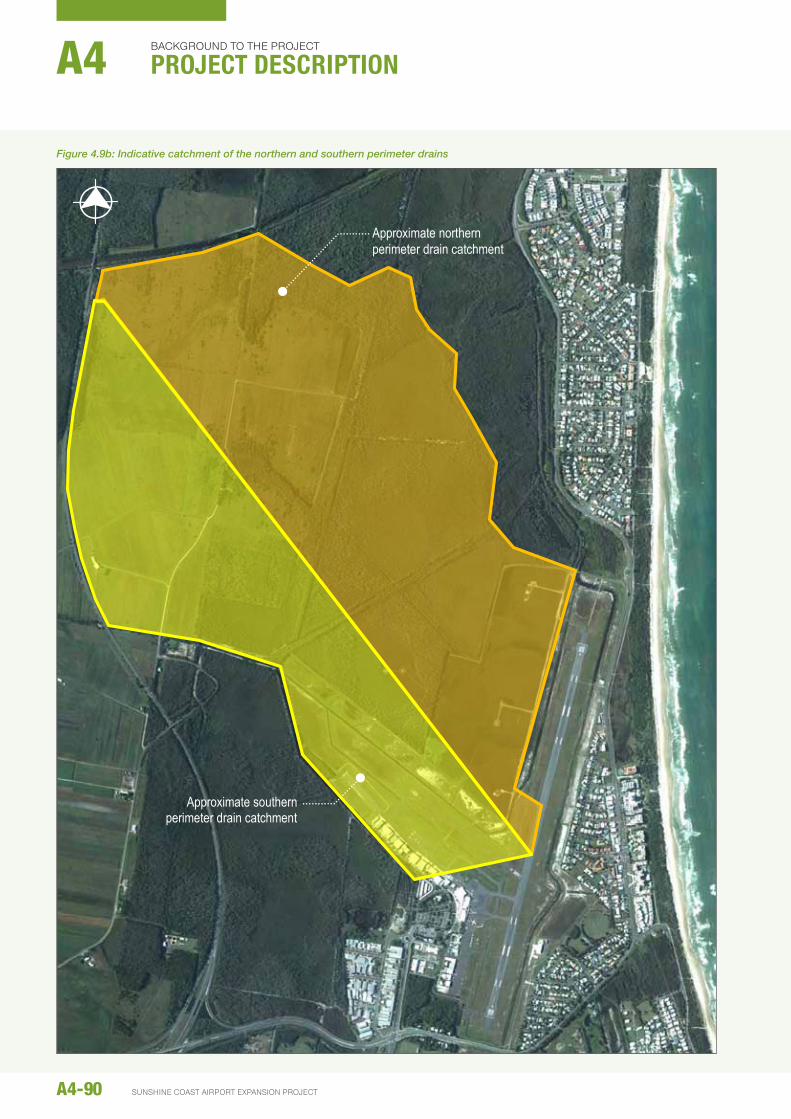
a northern perimeter drain (nPd) will be developed north of the new runway to direct stormwater from the runway and the area north of the runway into Marcoola drain. the approximate catchment of the nPd is shown in figure 4.9b. the nPd will be approximately 3 km long, running from the junction of rWY 13/31 and rWY 18/36 parallel to the new runway and connecting into Marcoola drain north- west of rWY 13/31. Marcoola drain is understood to be a man- made waterway, originally constructed to drain areas for cane farming.
the nPd will be located approximately 183 m from the runway centreline, to ensure that vehicles travelling on the airside perimeter road (which will be adjacent to the nPd) do not affect the performance of the runway strip (refer to Section 4.7.6). the drain will be 1.5 m deep and 10 m wide at the base (22 m wide at the top).
a western perimeter drain will also be established around the north-western end of the runway to assist in conveying floodwater past the runway. this drain will be 1.5 m deep with a 10 m wide base. the western perimeter drain will connect the nPd and southern perimeter drain (discussed below).
the existing southern perimeter drain will receive stormwater runoff from the western perimeter drain, runway and taxiways, and the existing developed areas of the airport. the southern perimeter drain will be maintained in its existing alignment along the Sca property boundary. From the Sca boundary, the southern perimeter drain flows west into the Maroochy river.
drawdown of the water table by the nPd was identified as a potential concern because of the very shallow groundwater table at the airport. consequently, the design includes a low-permeability cut-off wall on the northern side of the nPd to minimise groundwater flow into the drain.
Parts of the drains are tidally influenced and are expected to contain water in them at times. the presence of water may attract birds, which increases the risk of bird strike near a runway. consequently, measures are required to reduce the attractiveness of the drains to waterfowl and other birds. a description of bird strike management measures is included in chapter E6 – risk Management Plan.
4.9.2 minor drainage
Minor drainage for the runway and taxiways will direct stormwater into the southern perimeter drain. the drains will have concrete lined inverts, and be piped beneath the taxiways.
4.9.3 water quality
the key elements of the Project that potentially present a risk to stormwater quality are aircraft operation on the runway, taxiways and aprons. runoff from the airfield pavements will flow to the airfield drainage system, shown in figure 4.9a. before entering the minor and major drainage systems, the runoff will sheet flow through grassed areas between the asphalt and the drains. the length of sheet flow from the runway to the nPd is 160 m. based on studies at brisbane airport (reference: goonetillike a. et al, Stormwater Quality of Apron Runoff at Brisbane Airport, Qut, brisbane, 2006), it is anticipated that the treatment afforded by these grassed areas will be more than adequate to address stormwater quality. this is discussed further in chapter b6 – Surface Water.
4.10 extensIon oF AIRPoRt DRIve
airport drive is the main entry to the airport. It extends north from david Low Way, before splitting around the existing terminal car park, and continuing to the end of the existing western general aviation area. a two-lane extension (one lane each way) of airport drive will be constructed to service the new atc tower/arFFS station as shown in figure 4.10a.
4.11 PeRImeteR RoADs
an airside perimeter road will be developed to provide access to all parts of the airfield, including for maintenance and emergency response. Most of the perimeter road will be a sealed road on a built-up embankment; however, a section at the north-western end of the runway will be an at-grade unsealed access track, as shown in figure 4.11a.
4.12 seCURIty FenCInGSecurity fencing is critical to ensuring the safe and secure operations of the airport. the airside security fence delineates the secure airside areas and publicly accessible landside areas. the alignments of the existing and proposed airside security fences are shown in figure 4.11a.
the airside security fence will consist of a 2 m high chain mesh fence with a 0.4 m angled section of barbed wire. It will be continuous around the airside area, with a limited number of access points to/from landside areas. the fence will be regularly inspected and maintained to ensure its integrity.
the airside security fence currently encloses an area of habitat used by ground Parrots (refer to chapter b8). Evidence suggests the airside security fence is protecting the population from predation. the proposed airside security fence alignment will continue to enclose this area of habitat.
A4-88
background to the project
project descriptionA4
SunShIne coaSt aIrport eXpanSIon project

A4-89environmental impact statement
19 J
uly
2014
\\a
ubne
1fp0
03\p
roje
cts\
proj
ects
\602
4859
4\6.
dra
ft do
cs\6
.1 re
ports
\resc
ope
repo
rts\0
01_p
roje
ct d
escr
iptio
n\pr
ojec
t des
crip
tion
imag
es re
v f_
2014
0619
.doc
x 7
of 1
3
Figu
re 4
.10a
: Ind
icat
ive
drai
nage
layo
ut fo
r the
Exp
ansi
on P
roje
ct
North
ern p
erim
eter d
rain
South
ern p
erim
eter d
rain
(exis
ting)
Wes
tern p
erim
eter d
rain
Runw
ay dr
ain
Ma
rooc
hy R
iver
Ma
rcoola
drain
Figure 4.9a: Indicative drainage layout for the Project
A4-90 SUNSHINE COAST AIRPORT EXPANSION PROJECT
bACkgROUNd TO THE PROJECT
project descriptionA4
Figure 4.9b: Indicative catchment of the northern and southern perimeter drains
19 July 2014 \\aubne1fp003\projects\projects\60248594\6. draft docs\6.1 reports\rescope reports\001_project description\project description images rev f_20140619.docx 8 of 13
Figure 4.10b: Indicative catchment of the northern perimeter drain and southern perimeter drain
Approximate northern perimeter drain catchment
Approximate southern perimeter drain catchment

4.13 AIRFIeLD LIGhtInG
approach and ground lighting will be required for the proposed rWY 13/31. the proposed lighting scheme is illustrated in figure 4.13a and described below.
4.13.1 Approach lighting
approach lighting provides visual cues to the pilot of an aircraft during approach and landing. a Simple approach Lighting System (SaLS) will be provided to both ends of the runway. this will consist of runway centreline lights that extend beyond the threshold for 420 m, and consist of 6 m barrettes at 60 m intervals. a 30 m cross bar of lights will be located 300 m beyond the threshold.
In conjunction with the SaLS, high intensity runway lights (hIrL) may also be included, depending on the final operational requirements for the runway. hIrL assist pilots to make visual contact with the runway during their approach. hIrL have variable intensity controls, with high intensity only being used in very poor visibility conditions.
the approach lighting and hIrL would be within the Sca property boundary. the lights will be inset where they are located in the runway pavement, and supported on small structures beyond this.
In addition to the SaLS, Precision approach Path Indicators (PaPI) are also proposed to be installed. the PaPI is a visual aid that provides information to the pilot on the vertical location of the aircraft relative to the runway. the PaPI consists of an array of four equidistant light units positioned beside the runway; typically located 300 m from the runway end.
approach lights are directed towards the flight path of approaching aircraft. being designed to be seen by pilots, approach lights are typically not visible from ground level. approach lights are connected to the airfield lighting control system and are powered by mains electricity, with backup power from standby generators. typically, atc operates the approach lighting although pilot activation is occasionally used outside of atc hours.
4.13.2 Ground lighting system
ground lighting is the generic term used to describe the various lighting systems that are provided on an aerodrome for the guidance of pilots operating aircraft both at night and in low visibility conditions. It assists pilots to navigate aircraft when manoeuvring on the runway and taxiways.
the ground lighting system is integrated into a control system that allows atc to direct aircraft to the correct areas by turning ground lights on and off as appropriate.
Figure 4.10a: Indicative location of Airport Drive extension
19 July 2014 \\aubne1fp003\projects\projects\60248594\6. draft docs\6.1 reports\rescope reports\001_project description\project description images rev f_20140619.docx 9 of 13
Figure 4.11a: indicative location of Airport Drive extension
Airport Drive
Airport Drive extension
Proposed ATC tower/ ARFFS station
A4-91environmental impact statement

A4-92 SUNSHINE COAST AIRPORT EXPANSION PROJECT
bACkgROUNd TO THE PROJECT
project descriptionA4
Figure 4.11a: Indicative alignment of the existing and proposed airside perimeter fence and road
19 J
uly
2014
\\a
ubne
1fp0
03\p
roje
cts\
proj
ects
\602
4859
4\6.
dra
ft do
cs\6
.1 re
ports
\resc
ope
repo
rts\0
01_p
roje
ct d
escr
iptio
n\pr
ojec
t des
crip
tion
imag
es re
v f_
2014
0619
.doc
x 10
of 1
3
Figu
re 4
.12a
: Ind
icat
ive
alig
nmen
t of t
he e
xist
ing
and
prop
osed
airs
ide
perim
eter
fenc
e an
d ro
ad
New
Runw
ay 13
/31
Prop
osed
airsi
de pe
rimete
r fen
ce
Prop
osed
main
tenan
ce ac
cess
trac
k
Exist
ing ai
rside
perim
eter
fence
to re
main
Exist
ing ai
rside
perim
eter
fence
to be
remo
ved
Prop
osed
airsi
de pe
rimete
r roa
d
Exist
ing G
roun
d Par
rot h
abita
t
Exist
ing ai
rside
perim
eter r
oad

A4-93environmental impact statement
Figure 4.13a: Indicative proposed airfield lighting for RWY 13/31
19 J
uly
2014
\\a
ubne
1fp0
03\p
roje
cts\
proj
ects
\602
4859
4\6.
dra
ft do
cs\6
.1 re
ports
\resc
ope
repo
rts\0
01_p
roje
ct d
escr
iptio
n\pr
ojec
t des
crip
tion
imag
es re
v f_
2014
0619
.doc
x 11
of 1
3
Figu
re 4
.14a
: Ind
icat
ive
prop
osed
airf
ield
ligh
ting
for R
WY
13/3
1
New
Runw
ay 13
/31
Prec
ision
path
appr
oach
ind
icator
s (PA
PI)
Gree
n tax
iway
ce
ntreli
ne lig
hts
Simp
le ap
proa
ch
lighti
ng sy
stem
Ru
nway
edge
lights
(60 m
spac
ing)
Gree
n thr
esho
ld lig
hts
Blue
taxiw
ay ed
ge lig
hts
Red r
unwa
y end
lights
NOTE
: Airfi
eld lig
hting
labe
lled
at no
rth-w
est e
nd on
ly

A4-94 SUNSHINE COAST AIRPORT EXPANSION PROJECT
bACkgROUNd TO THE PROJECT
project descriptionA4
ground lighting for the new runway will include:
y omni-directional white runway edge lights located at 60 m centres
y bi-directional green threshold lights at each runway threshold
y red stopway directional lights located with white runway edge lights (for take-off) at the threshold
y red stopway directional lights located at the end of the stopway
y green taxiway centreline lights located close to the taxiway centreline marking
y green/yellow taxiway centreline lights located at exit taxiways
y blue taxiway elevated omnidirectional lights located on the curves of taxiway shoulders
y PaPI located on both sides of the runway for operation in both directions
y Mandatory and information Movement area guidance Signs (MagS) located to indicate the location of aircraft and taxiway/runway designations.
Most of these lights are inset in the runway and taxiway pavements, although some, such as the MagS are located near the runway or taxiway at ground level.
the ground and approach lighting control systems will be located in a new aerodrome Lighting Equipment room (aLEr), which will be located at the end of the runway.
the aLEr will house the constant current regulators, electrical switchboards and standby generators, and will be climate controlled.
In addition to the ground lighting described above, there will also be:
y Illuminated wind socks located at each end of the runway, and
y apron flood lighting compliant with MoS 139 with high mast lighting and metal halide floodlights.
4.13.3 Design considerations
the preliminary lighting design is consistent with current MoS 139 and other industry requirements. however, it may be necessary to update the design before construction to accommodate any changes to caSa or Icao requirements.
4.14 AtC toweR AnD ARFFs stAtIon
a 2008 study identified a number of potential atc tower locations for the new runway (airbiz, 2008); this was updated in 2010 when the configuration of the new runway was refined during the preliminary design (aEcoM, 2010). the 2010 assessment indicated that the atc tower would need to be located south of rWY 13/31 towards the middle of
the runway’s length. In line with current airservices australia philosophy, provision has been made to allow the co-location of the arrFS facilities with the atc tower.
the required tower height has been estimated at 55 m above ground level, although this will be confirmed in later design stages.
4.15 seRvICes
the Project will require some existing services to be relocated and also the installation of new trunk services. the relocation of existing services will need to occur before construction of the new runway earthworks platform, while new services will be established to serve the development of the new runway and atc/arFFS facility. figure 4.15a shows the location of existing utilities at the airport.
4.15.1 existing services
Existing services within the Project footprint include:
y Water: currently a 450 mm diameter water main, owned by unitywater, runs along Finland road through the proposed runway site. the 450 mm diameter water main is a critical trunk main, being the sole supply to coolum and Peregian. the existing main is a ductile iron cement lined (dIcL) pipe, which has been severely corroded by the acidic conditions attributed to the presence of acid Sulphate Soils.
In 2012, unitywater undertook a program of replacing the dIcL water main with polyethylene (PE) pipe along the same alignment (both vertical and horizontal). the main has been replaced nearly to the extents of Sca. unitywater wishes to replace the remaining portion through the proposed new runway site in 2013/2014. the main will need to be realigned to ensure that unitywater have clear access to their asset without interruption to airport operations.
the replacement main has been installed in the verge of Finland road west of the motorway, which will be used as a construction access road for the new runway. construction traffic for the proposed runway should not affect the new main on this road.
y recycled water supply: an existing recycled water supply to the airport was used during drought conditions for irrigation.
y Sewer: currently the airport is serviced by a combination of pressurised and gravity sewers. the closest sewer to the proposed atc tower is located in front of the aviation business buildings at the existing airport.
y communications: communications services are provided to the airport along the existing service road and terminate near the existing terminal.

A4-95environmental impact statement
Figure 4.15a: Existing utilities locations
19 July 2014 \\aubne1fp003\projects\projects\60248594\6. draft docs\6.1 reports\rescope reports\001_project description\project description images rev f_20140619.docx 12 of 13
Figure 4.16a: Existing utilities locations
Existing overhead power lines and water main
Existing water main and sewer
Existing sewer

y Power: an underground electrical service is located close to Friendship avenue. the existing electrical service runs west along the road reserve and supplies power to the existing aviation business buildings. the electrical service continues west where an electrical substation is located on the northern side of the road.
as the proposed road reserve for the airport drive extension encroaches on the western end of the existing aviation businesses and adjacent undeveloped land, the existing electrical services and electrical substation will need to be relocated.
overhead power lines traverse the proposed airport precinct and runway along Finland road.
4.15.2 Relocations
the following relocations are proposed as part of the Project:
a) Water: It is proposed to relocate the existing 450 mm diameter water main from Finland road into the Sunshine Motorway corridor east of the road. the relocation is required to ensure that unitywater has access to their asset and that there are no interruptions to critical airport operations.
the proposed alignment of the relocated water main is as follows:
− the relocated main will connect to the existing main where Finland road crosses the Sunshine Motorway
− It will then travel north within the Motorway corridor east of the road until it reaches the southern side of Marcoola drain
− the main will follow Marcoola drain east
− It will connect into the existing main to the north of the Project at Finland road.
as this water main is a critical asset for unitywater, they are undertaking the relocation as part of their network upgrade works in 2013/2014, and it is therefore outside the scope of this EIS.
b) Power: overhead power lines traverse the proposed runway along Finland road. It is proposed that this electrical service be relocated underground and to the west of the new runway.
4.15.3 new services
the following new services as shown in figure 4.15b will be established:
a) Water: a pipe size of nominal diameter (dn) 150 mm is proposed to be installed for water supply to the atc/ arFFS facility. the proposed connection point into the existing water system will be from david Low Way at the southern end of the existing road reserve. It is proposed that a dn150 water main will run north along the existing road reserve and continue west (within the drainage/buffer corridor) along the road reserve to supply water to the proposed atc/arFFS facility.
the pipes will be dn 150 mm dIcL pressure number 35 (Pn35), based on the requirements of Maroochy Plan 2000 Planning Scheme Policy no. 5 – operational Works (unitywater’s Standards for Water and Sewerage).
b) Sewer: Sewage from the Project will be disposed of through the existing sewer network. a new 225 mm diameter sewer will connect the atc/arFFS facility to an existing manhole south of the existing aerospace business area. based on the Maroochy Plan 2000 Planning Scheme Policy no. 5 – operational Works (unitywater’s Standards for Water and Sewerage) it is proposed to use PE Stiffness number (Sn) 8 sewer pipes.
c) Power: the proposed electrical alignment will connect into the existing electrical service near the terminal. the new electrical service will then run west (within the proposed services corridor) along the road reserve to supply the atc/arFFS facility.
It is envisaged that the existing EnErgEX high voltage (11kV) network will be extended from the existing substation, terminating at local substations incorporated into the building development and 415V power will be distributed to the aLErs as required.
the estimated power demands for the airfield is 200 kVa and for the atc/arFFS facility is 600 kVa.
d) communications: although precise requirements for communications will not be known until more detailed planning for the atc/arFFS facility has been undertaken, provision of communications to the new development is required.
the proposed communications alignment will connect into the existing communications service near the terminal. the new communications service will then continue north within the road reserve, where it will then run west (within the proposed services corridor) along the road reserve to supply the atc/arFFS facility.
4.16 LAnDsCAPInG
4.16.1 existing landscape features
the existing landscape for the Project lies within the relatively flat flood plain of the Maroochy river. Most of the area is characterised by grassland or old cane farms, although there is an area of native woodland within the construction footprint.
the project will be visible from the Sunshine Motorway and Mt coolum, but somewhat screened as a result of a rehabilitated corridor that is proposed on the east of the motorway corridor on Sca-owned land (see chapter b8 – terrestrial Fauna).
the landscape and visual assessment and proposed mitigation measures are discussed in chapter b17 –Landscape and Visual.
A4-96
background to the project
project descriptionA4
SunShIne coaSt aIrport eXpanSIon project

A4-97environmental impact statement
Figure 4.15b: Indicative proposed utilities locations
19 July 2014 \\aubne1fp003\projects\projects\60248594\6. draft docs\6.1 reports\rescope reports\001_project description\project description images rev f_20140619.docx 13 of 13
Figure 4.16b: Indicative proposed utilities locations
Realigned underground power lines and water main
New water main, fibre optic and sewer
New water main and fibre optic