Project Cargo – Stowage and Securing CSM includes vessel specific information on: Specification of...
69
Project Cargo – Stowage and Securing Bangkok, Thailand, 13 th March 2018 Capt. Simon Rapley
Transcript of Project Cargo – Stowage and Securing CSM includes vessel specific information on: Specification of...

Project Cargo –Stowage and Securing
Bangkok, Thailand, 13th March 2018
Capt. Simon Rapley

Introduction
■ Simon Rapley■ Loss Prevention Manager, West of England P&I Club, London■ Master Mariner, ex. Ship’s Captain■ 60 Minute presentation■ Project cargo - stowage and securing - what we will be covering:
■ Regulatory Requirements and Recommendations■ Stowage ■ Lashings - Principles■ Types of Lashings■ Welding and NDT■ Lashings Calculations■ Difficult Cargoes

Regulatory Requirements and Recommendations

Cargo Securing Manual (CSM)
■ Required on all vessels carrying cargo other than solid bulk and bulk liquid cargoes
Cargo Securing Manual (CSM)
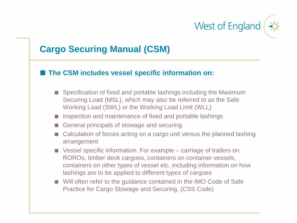
■ The CSM includes vessel specific information on:
■ Specification of fixed and portable lashings including the Maximum Securing Load (MSL), which may also be referred to as the Safe Working Load (SWL) or the Working Load Limit (WLL)
■ Inspection and maintenance of fixed and portable lashings■ General principals of stowage and securing■ Calculation of forces acting on a cargo unit versus the planned lashing
arrangement■ Vessel specific information. For example – carriage of trailers on
ROROs, timber deck cargoes, containers on container vessels, containers on other types of vessel etc. including information on how lashings are to be applied to different types of cargoes
■ Will often refer to the guidance contained in the IMO Code of Safe Practice for Cargo Stowage and Securing, (CSS Code)

IMO CSS Code – Guidelines and Recommendations
International Maritime Organisation (IMO) - Code of Safe Practice for Cargo Stowage and SecuringLatest Edition - 2011
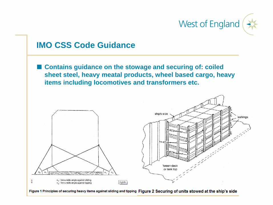
IMO CSS Code Guidance
■ Contains guidance on the stowage and securing of: coiled sheet steel, heavy meatal products, wheel based cargo, heavy items including locomotives and transformers etc.

Stowage

Stowage Position - Accelerations

Club Rules - Cargo Stowed on Deck
■ Cargo must be suitable for stowage on deck
■ Contract of carriage must specify that the cargo can be carried on deck
■ Contract of carriage must exempt the carrier from liability for cargo loss or damage
or
■ Carrier has rights, immunities, limitations under the Hague, Hague – Visby (specifying deck cargo) or Hamburg Rules
■ Check with Underwriters first to ensure cover is in place
Stowage Position – Sea and Wind Affects
■ Force due to sea sloshing: 1 kN per m2 (only applied to a height of 2 m above the deck or hatch top, as applicable). Forces much higher than this may be encountered
■ Force due to wind pressure: 1 kN per m2
Stowage Position – Other Considerations
■ Is there adequate space for all the lashings, including the angles/leads required?
■ Are there sufficient lashing points available?■ Will the stowage position compromise the vessel’s stability?■ Consider the port rotation■ Can the cargo be stowed up against a bulkhead?

Stowing Cargo – Deck Capacity
CompartmentMaximum permissible
load in tonnes / m2
Lower hold 10Tweendeck 5Hatch cover 2.5
Weather deck 2.5
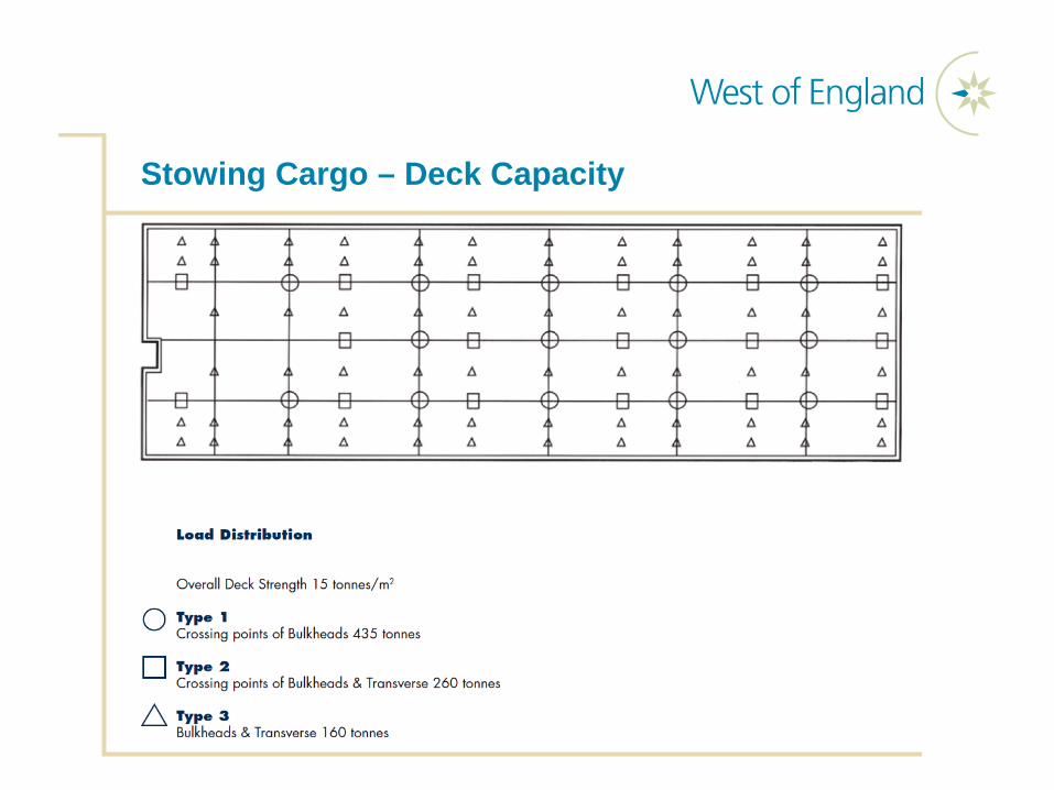
Stowing Cargo – Deck Capacity
Stowage of Cargo - Dunnage
■ Why do we place dunnage under a cargo:■ To spread the load■ Friction■ Raise cargo clear of water / sweat on deck■ To protect the deck / hatchcovers■ To chock wheeled cargo
■ Dunnage should be:■ Supplied in sufficient quantities■ Undamaged■ Clean■ Dry■ Free of oil and grease■ Free of infestation■ Of sufficient strength for the intended use■ Should not extend beyond the cargo’s footprint when stoppers are to be
used

Lashings - Principles
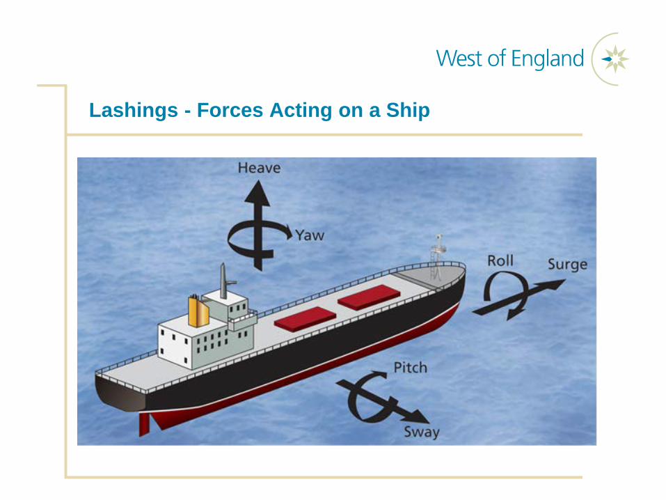
Lashings - Forces Acting on a Ship

Lashings - Movement of Cargo

Lashings – Basic Application of Lashings
Tipping / Toppling
Sliding

Types of Lashings

Wooden Shoring / Chocking

Wooden Shoring / Chocking

Wooden Shoring / Chocking

Fixed Lashings - D Rings

Fixed Lashings - D Rings

Lashings - Wires, Wedge Sockets & Turnbuckles

Wires – General Considerations
■ Wires should be in good condition and certified■ Hard eyes are preferred to soft eyes■ Wires may stretch in service, requiring regular checking, and
possibly adjustment■ Bulldog grips used to form eyes should be properly applied:
“Never saddle a dead horse” – the saddle must be on the live part of the wire

Wires – General Considerations
A CB

Lashings – No Securing Points
Friction Loops – Don’t Use!

Lashings – No Securing Points
Silly Loops – Don’t Use!

Lashings – Cargo Without Lashing Points

Lashings - Chains, Bottle Screw, Chain Tensioner

Chains – General Considerations
■ Don’t use chains with bent, damaged elongated or cracked links or hooks, or with significant corrosion
■ Never weld to a link or hook, as this may affect the SWL/MSL
■ Don’t lead around obstructions
■ Locking nuts on turnbuckles should be tightened
Web Lashings – General Considerations
■ Not usually used for heavy items
■ Useful for items including crates and boxes that are not provided with lashing points
■ Should not be led around sharp edges, protection should be used to prevent chafing
■ Due to manual tightening using ratchets, it can be difficult to achieve equal tension in lashings on the same side of the cargo
■ Web lashings should not be knotted – this reduces their strength considerably

Lashings – Shackles

Shackles – General Considerations
■ Should be marked with their SWL / MSL and certified
■ Mismatched shackle bodies and pins are not to be used
■ All pins must be securely tightened and moused with seizing wire
■ Nuts should be securely tightened onto bolts, and split pins fitted and fully opened. Welding rods should not be used for this purpose
■ Do not weld on shackles as it reduces their strength

Fixed Lashings – Stoppers

Fixed Lashings - Stoppers

Welding and NDT

Welding Best Practice
■ All welding should be on strong points on the deck / hatch cover, with welding positions ideally marked out in advance
■ It must be ensured that there is no fire risk due to the heat generated / burn through due to the welding operation (i.e. other cargo in adjacent spaces, or welding on fuel tanks)
■ Safety Management System hot work procedures must be followed by all personnel including external contractors
■ All welders should be suitably qualified for the work
■ Stoppers should not be welded to the cargo, only the vessel

Welds
Butt Weld
Fillet Weld

Welds – Inspection & Non Destructive Testing (NDT)
■ All welds on grillage, lashings and securing devices should be subject to a thorough visual inspection and NDT, by a suitably qualified inspector
■ Due to the risk of delayed hydrogen cracking of welds, inspection and NDT should not commence until a suitable time period has elapsed
■ The time delay required will depend on the size of the weld, heat input to the weld and the standards / criteria applied. The time can vary from between allowing the weld to cool, to leaving the weld for over 48 hours
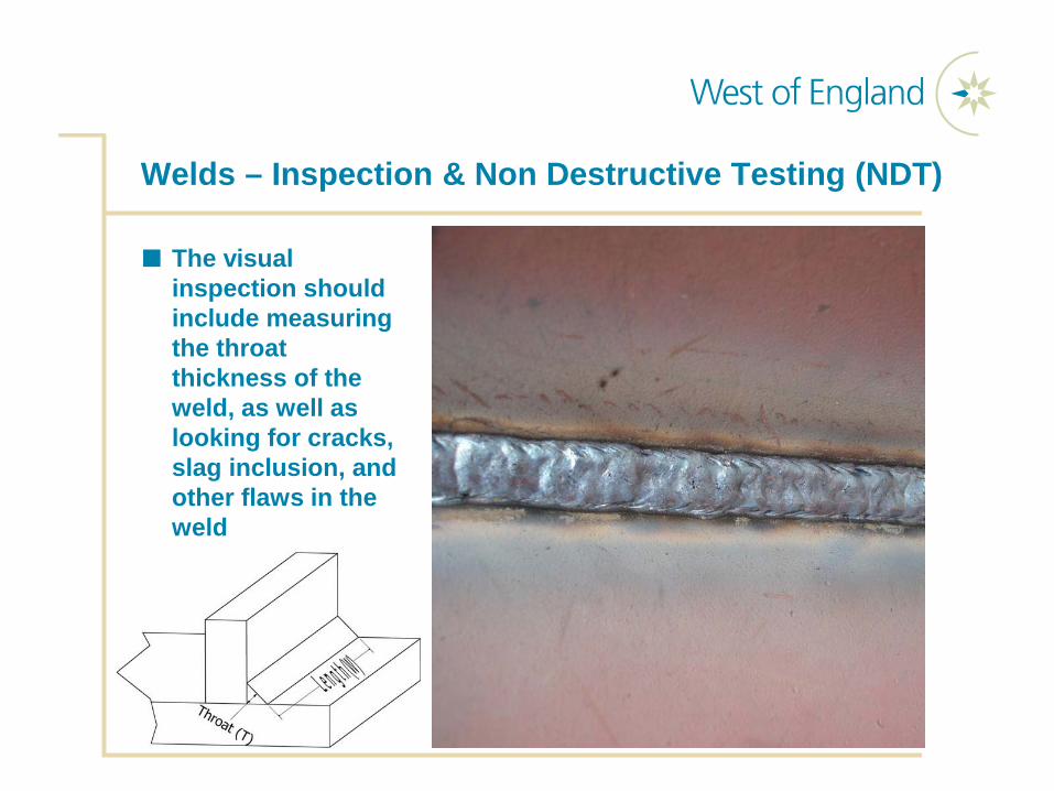
Welds – Inspection & Non Destructive Testing (NDT)
■ The visual inspection should include measuring the throat thickness of the weld, as well as looking for cracks, slag inclusion, and other flaws in the weld

Welds –Non Destructive Testing (NDT)
■ NDT can be undertaken using:
■ Dye penetrant testing (PT) – only detects flaws open on the surface; dye is applied to the surface and highlights defects
■ Magnetic Particle inspection (MPI) – only detects flaws open on the surface; magnetic particles are sprayed onto the weld, a magnetic field is then applied, magnetic particles highlight defects
■ Ultrasonic Testing – can detect flaws within the weld, however, it is mostly suitable for butt welds, not fillet welds, therefore, due to this limitation it is not normally used for seafastenings

Dye Penetrant – Weld Testing
■ Can be done relatively quickly and is inexpensive
■ Dye Penetrant procedure:
■ Clean surface■ Spray penetrant and allow it to
“dwell” for up to 30 minutes –the smaller the flaw, the longer the dwell time required
■ Remove excess penetrant from the surface
■ Apply white developer to the surface, this draws the penetrant from the defects, giving a visible indication of flaws

MPI Weld Testing
■ Can be carried out relatively quickly and inexpensively
■ MPI Procedure:■ Clean surface■ Apply white contrast paint■ Apply magnetic pulse to part
while simultaneously applying magnetic powder / dust
■ Remove magnetic field after approximately 2-3 seconds
■ Magnetic field applied twice from directions perpendicular to one another as indications only appear at an angle of 45 to 90 from the magnetic field
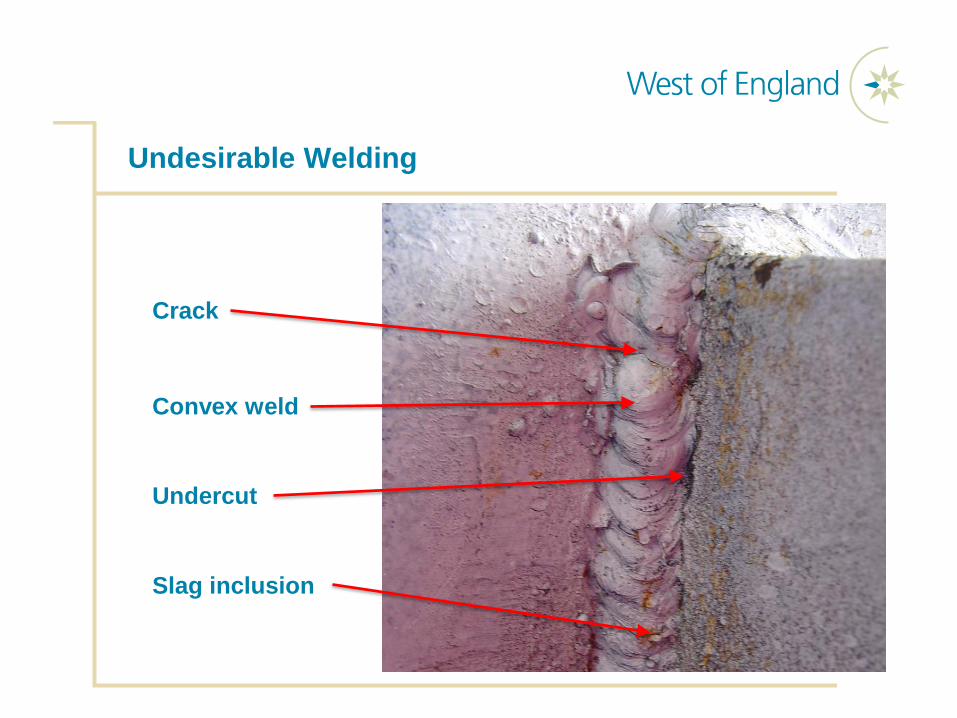
Undesirable Welding
Crack
Convex weld
Undercut
Slag inclusion

Lashing Calculations

Lashing Calculation – Rule of Thumb
■ Contained in the IMO CSS Code
■ Enables the seafarer to quickly determine the number of lashings for an item of cargo, regardless of vessel size, stability, stowage location and area of operation. Best suited to smaller cargo items
■ The total of the MSL / SWL / WLL values of the securing devices on each side of the cargo unit (port as well as starboard) should equal the weight of the unit (the capacity of the lashings and the weight of the cargo unit being taken in kN)
■ kilo Newtons (kN), where 1 metric tonne equals 9.81 kN

Lashing Calculation – Rule of Thumb
■ The Rule of Thumb assumes:
■ Suitable material is used to provide friction■ The angle between the transverse lashings and the horizontal does not
exceed 60˚ ■ Where transverse lashings with an angle of greater than 60˚ are used to
prevent tripping, these are not counted when using this method

Advanced Lashing Calculation
■ Two methods in CSS Code:■ Balance of forces and moments■ Balance of forces – alternative method
■ Calculation steps – balance of forces and moments method:■ Determination of the forces acting on the cargo unit■ Determination of the cargo securing arrangements■ Calculation of the balance of lashing forces – transverse sliding■ Calculation of the balance of lashing forces – transverse tipping■ Calculation of the balance of forces – longitudinal sliding
■ The alternative calculation method also considers the horizontal angle of the lashings

Determination of Cargo Forces

Determination of Cargo Securings
■ To complete the calculation we need to determine:
■ The number of lashings to port and starboard■ The MSL of each lashing arrangement (MSL of the lowest rated
component)■ The Calculated Strength (CS) of each component (MSL / 1.5)■ The vertical angle between the horizontal and each lashing■ The friction co-efficient for the material between the cargo and the deck■ The lever arms of tipping, stableness and securing force

Calculation of Lashing Factors
Material MSLShackles, D Rings, deckeyes, turnbuckles of mild steel
50% of breaking strength
Fibre rope 33% of breaking strengthWeb lashing 70% of breaking strengthWire rope (single use) 80% of breaking strengthWire rope (re-useable) 30% of breaking strengthSteel band (single use) 70% of breaking strengthChains 50% of breaking strength
Materials in Contact Friction Coefficient (µ)
Timber on timber, either wet or dry 0.4Steel on timber or steel on rubber 0.3Steel on steel, dry 0.1Steel on steel, wet 0.0
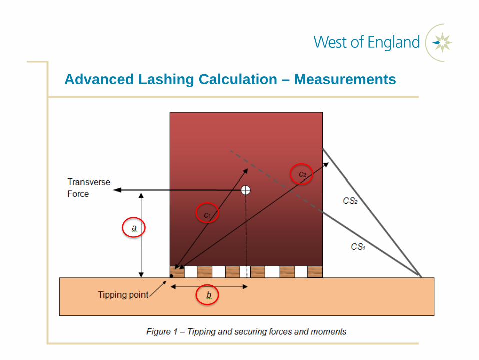
Advanced Lashing Calculation – Measurements

Lashing Factors

Lashing Calculations
■ Transverse sliding formula■ Transverse Force ≤ µ x Mass of Cargo x 9.81 m/s2 + No. of lashing type
1 x CS x f + No. of lashing type 2 x CS x f + No. of lashings type 3 x CS…..
■ Transverse tipping formula■ Transverse Force x a ≤ b x Mass of Cargo x 9.81 m/s2 + No. of lashing
type 1 x CS x c + No of lashings type 2 x CS x c + No. or lashing type 3 x CS x c….
■ Longitudinal sliding formula■ Longitudinal Force ≤ µ(Mass of Cargo x 9.81 m/s2 – Vertical Force) +
No. of lashing type 1 x CS x f + No. of lashing type 2 x CS x f + No. of lashings type 3 x CS…..

Lashing Calculation - DNV Software – Lashcon IMO

Lashings – General Considerations
■ In practice around 70 to 80% of lashings will have a transverse (athwartships) component
■ Lashings must be balanced to port and starboard, as well as forward and aft
■ Lashings should be led in a straight line between securing points on the cargo and the vessel
■ Tension in the lashing will increase the friction between the cargo and the vessel
■ Lashings should not be unduly long, as they will be affected by stretch / elongation

Lashings – General Considerations
■ When evaluating the strength of a lashing the SWL / MSL of the lowest rated component will be used
■ Lashing should commence as soon as possible after the cargo has been landed

Difficult Cargoes
Difficult Cargoes – Anchor Chain

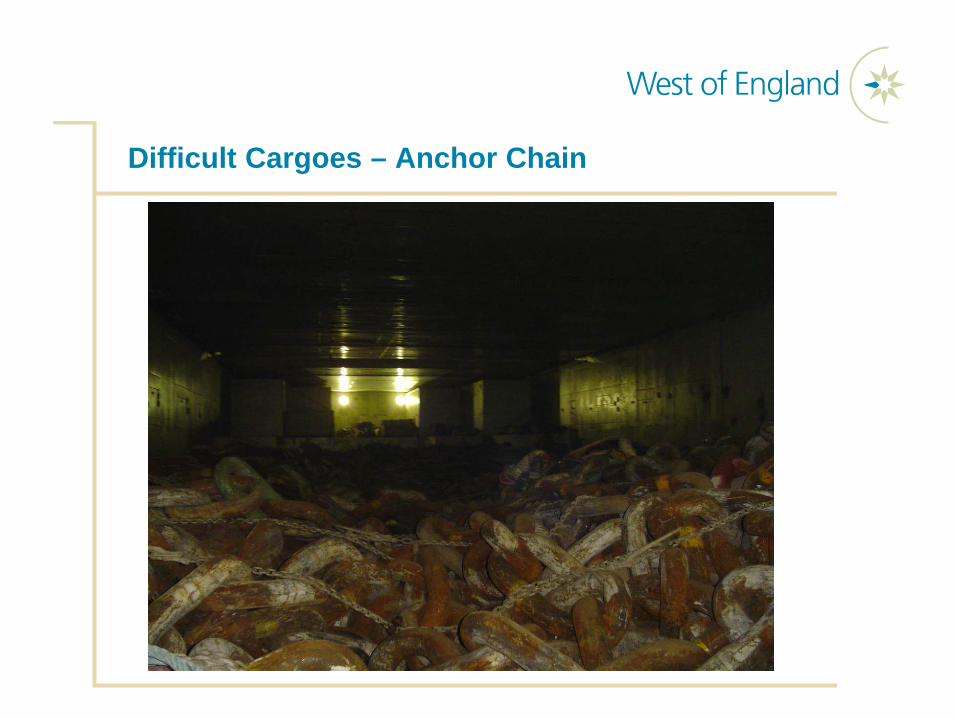
Difficult Cargoes – Anchor Chain
■ Can be difficult to secure■ Stowed on the tanktop, can give rise to a large GM and a very
“stiff” vessel, and hence large dynamic forces
■ Stowage:■ Surfaces must be free of oil and grease■ Must be stowed on wooden dunnage, never load directly on metal
surfaces■ Where practical stow against and between bulkheads■ When loaded in bundles, leave lifting slings in place and secure ends
together■ Lash bundles to bulkheads, and to each other, to achieve a tight stow■ Pass lashings over the stow to hold it down, both transversely and
longitudinally.

Difficult Cargoes – Anchor Chain

Difficult Cargoes – Anchor Chain

Difficult Cargoes – Yachts and Boats
■ Stow carefully clear of bow and ship’s sides. Protect with other cargo if necessary. Fit plywood on boat’s windows
■ A substantial welded metal cradle, designed for the particular boat, is preferred over a wooden cradle
■ Cradle should be designed to withstand the dynamic forces expected during the sea passage
■ Cradle transverse structure must align with strength members of the boat
■ Cradle should be fitted with sufficient dunnage and padding to prevent damage / marking of the boat hull
Difficult Cargoes – Yachts and Boats
■ Lashings should be applied:■ From boat to deck■ From cradle to deck■ From boat to cradle
■ Use strong points on the boat, often mooring furniture is used, although individual lashing points must not be overloaded
■ Use soft nylon lashings or protection must be fitted between lashings and the boat to prevent damage
■ Lashings must not be over tightened as this can damage the boat
■ Claims for damage often occur due to cargo being worked next to the boat, or other cargo impinging on the boat
Checking the Securing Arrangements
■ After the cargo is stowed and secured; check and verify the following:
■ All lashings fitted in accordance with the lashing plan – number, position, type and composition
■ All lashings equally tensioned■ Horizontal and vertical lashing angles correspond with the lashing plan■ Wire grip (bulldog grip) nuts tensioned■ All locking devices fitted – split pins, locking nuts, locking pins etc.■ Check the actual sailing GM against the GM used for the lashing plan –
is the lashing arrangement still suitable?■ Retain lashing calculation onboard■ Take plenty of photographs of the stowage and securing arrangement
prior to departure■ In some cases, approval of the stowage and securing arrangement may
be required from a third party surveyor, e.g. a Marine Warranty Surveyor

Thank You
Any Questions?
www.westpandi.com


![StowMan[S] - · PDF fileIt is a stowage decision support tool based on ... n scenarios keeping doors open for ... Lashings can automatically be applied according to the Cargo Securing](https://static.fdocuments.in/doc/165x107/5a85c2587f8b9afc5d8c9af8/stowmans-is-a-stowage-decision-support-tool-based-on-n-scenarios-keeping.jpg)