Project Basic Design - Italy
97
E.ON New Build & Technology GmbH Page 1 of 97 Area Code Comp. Code System Code Disc. Code Doc.- Type Ser. No. Saipem SpA Via Toniolo n. 1 61032 Fano - Italy IAL00-SPF-000-A-TRE-0001 Rev.: 00 Ordering Unit: Trans Adriatic Pipeline AG LF-E-82000 Owner: Saipem Fano Project Title: Trans Adriatic Pipeline – TAP Document Title: Project Basic Design - Italy Rev. Purpose of Issue Remark/Description Orig. Date 0A Issued for DIC First Preparation MAC 2013-06-10 0B Issued for IDC MAC 2013-06-17 0C Issued for Review Incorporation of comments, photolog & flow scheme added MAC 2013-06-24 0D Issued for Review MAC 2013-07-19 0E Issued for Acceptance MAC 2013-08-22 00 Issued for Information Aligned with the ESIA Italian version REV. 00 MAC 2013-09-16 Final Purpose of Issue: Issued for Information CONTRACTOR TSPE & TSPW Originator Checked Approved Name/Signature Magliola, Carlo Ricci Luigi Mazzanti, Sara Date 2013-09-16 2013-09-16 2013-09-16 Org. / Dept. Saipem Saipem Saipem Document Status Preliminary Checked Approved Checked/Approved Checked/Approved
Transcript of Project Basic Design - Italy

E.ON New Build & Technology GmbH
Page 1 of 97
Area Code
Comp. Code
System Code
Disc. Code
Doc.- Type
Ser. No.
Saipem SpA Via Toniolo n. 1 61032 Fano - Italy
IAL00-SPF-000-A-TRE-0001 Rev.: 00
Ordering Unit: Trans Adriatic Pipeline AG LF-E-82000
Owner: Saipem Fano
Project Title: Trans Adriatic Pipeline – TAP
Document Title:
Project Basic Design - Italy
Rev. Purpose of Issue Remark/Description Orig. Date
0A Issued for DIC First Preparation MAC 2013-06-10
0B Issued for IDC MAC 2013-06-17
0C Issued for Review Incorporation of comments, photolog & flow scheme added MAC 2013-06-24
0D Issued for Review MAC 2013-07-19
0E Issued for Acceptance MAC 2013-08-22
00 Issued for Information Aligned with the ESIA Italian version REV. 00 MAC 2013-09-16
Final Purpose of Issue: Issued for Information
CONTRACTOR TSPE & TSPW Originator Checked Approved
Name/Signature Magliola, Carlo Ricci Luigi Mazzanti, Sara
Date 2013-09-16 2013-09-16 2013-09-16
Org. / Dept. Saipem Saipem Saipem
Document Status Preliminary Checked Approved Checked/Approved
Checked/Approved

E.ON New Build & Technology GmbH
Saipem SpA
Page 2 di 97 Area Code
Comp. Code
System Code
Disc. Code
Doc.- Type
Ser. No.
Project Title: Trans Adriatic Pipeline – TAP IAL00-SPF-000-A-TRE-0001 Rev.: 00 Document Title: Project Basic Design - Italy
Table of contents
1 INTRODUCTION 5
2 DESIGN DATA 7 2.1 Offshore Section (Adriatic Sea to Landfall Microtunnel entry point) 7 2.2 Onshore Section (From Landfall Microtunnel entry point to PRT) 14 2.3 Pipeline Receiving Terminal (PRT) 20
3 ROUTE SELECTION CRITERIA 35 3.1 Offshore Section 35 3.2 Onshore Section 35
4 PIPELINE ROUTE DESCRIPTION 37 4.1 Offshore, Nearshore and Landfall Sections 37 4.2 Onshore Section 40
5 CONSTRUCTION METHOD AND INSTALLATION 42 5.1 Offshore, Nearshore and Landfall Sections 42 5.2 Onshore Section 71
6 CONSTRUCTION TIMING 75
ANNEX A - PHOTOGRAPHIC REPORT 76
ANNEX B – TYPICAL DRAWINGS 83
E.ON New Build & Technology GmbH
Saipem SpA
Page 3 di 97 Area Code
Comp. Code
System Code
Disc. Code
Doc.- Type
Ser. No.
Project Title: Trans Adriatic Pipeline – TAP IAL00-SPF-000-A-TRE-0001 Rev.: 00 Document Title: Project Basic Design - Italy
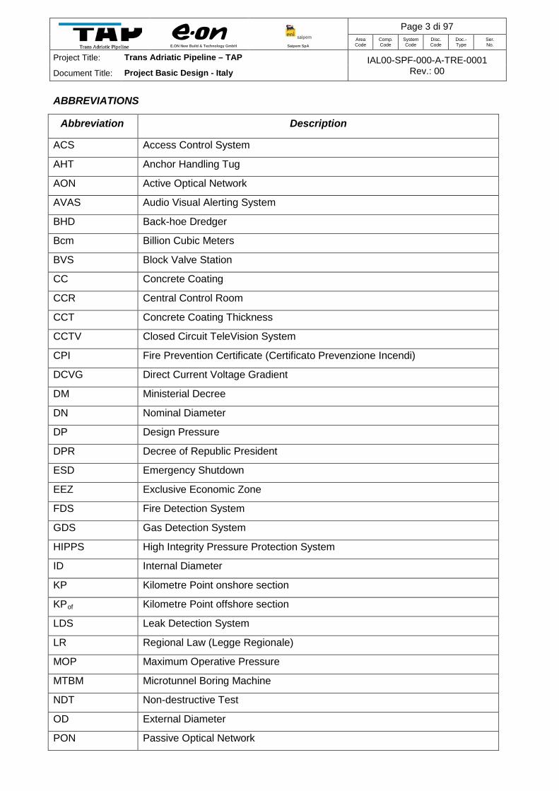
ABBREVIATIONS
Abbreviation Description
ACS Access Control System
AHT Anchor Handling Tug
AON Active Optical Network
AVAS Audio Visual Alerting System
BHD Back-hoe Dredger
Bcm Billion Cubic Meters
BVS Block Valve Station
CC Concrete Coating
CCR Central Control Room
CCT Concrete Coating Thickness
CCTV Closed Circuit TeleVision System
CPI Fire Prevention Certificate (Certificato Prevenzione Incendi)
DCVG Direct Current Voltage Gradient
DM Ministerial Decree
DN Nominal Diameter
DP Design Pressure
DPR Decree of Republic President
ESD Emergency Shutdown
EEZ Exclusive Economic Zone
FDS Fire Detection System
GDS Gas Detection System
HIPPS High Integrity Pressure Protection System
ID Internal Diameter
KP Kilometre Point onshore section
KPof Kilometre Point offshore section
LDS Leak Detection System
LR Regional Law (Legge Regionale)
MOP Maximum Operative Pressure
MTBM Microtunnel Boring Machine
NDT Non-destructive Test
OD External Diameter
PON Passive Optical Network

E.ON New Build & Technology GmbH
Saipem SpA
Page 4 di 97 Area Code
Comp. Code
System Code
Disc. Code
Doc.- Type
Ser. No.
Project Title: Trans Adriatic Pipeline – TAP IAL00-SPF-000-A-TRE-0001 Rev.: 00 Document Title: Project Basic Design - Italy
Abbreviation Description
OLB Offshore Lay-barge
PRT Pipeline Receiving Terminal
PSA Piping Stress Analysis
ROW Right of Way
SCADA Supervisory Control and data Acquisition System
SG Specific Gravity
SP Provincial Road (Strada Provinciale) SRG Snam Rete Gas
SS National Road (Strada Statale)
TAP Trans Adriatic Pipeline
TBM Tunnel Boring Machine
UXO Unexploded Ordnance
VIV Vortex Induced Vibration
WD Water Depth
WF Weight Factor
WT Wall Thickness

E.ON New Build & Technology GmbH
Saipem SpA
Page 5 di 97 Area Code
Comp. Code
System Code
Disc. Code
Doc.- Type
Ser. No.
Project Title: Trans Adriatic Pipeline – TAP IAL00-SPF-000-A-TRE-0001 Rev.: 00 Document Title: Project Basic Design - Italy
1 INTRODUCTION
Trans Adriatic Pipeline will transport gas via Greece and Albania and across the Adriatic Sea to
Italy’s southern Puglia Region and further to Western Europe. Crossing the Adriatic Sea from
central-western Albania, the offshore pipeline gets onshore in south-east Italy and ties in to the
Italian gas network South of Lecce.
Across the Adriatic Sea the gas will be transported via a 36” pipeline to an onshore receiving
terminal (TAP Receiving Terminal) that will be connected to the existing Snam Rete Gas network.
The project is aimed at enhancing security of supply as well as diversification of gas supplies for
the European markets. TAP has also incorporated provisions to accommodate physical reverse
flow. The total pipeline length is 871 km approximately.
The pipeline system in Italy would consist of an approximately 45 km long offshore pipeline, from
the Italian jurisdiction boundary (middle of the Adriatic Sea) to the Italian coast (KPof 60.144 –
KPof 104.975, considering KPof 0 the Albanian Landfall), an approximately 8.2 km long onshore
pipeline (KP 0 – KP 8.203), considering KP 0 the entry point of the offshore microtunnel, and a
Pipeline Receiving Terminal (also referred to as PRT) near Melendugno in the province of Lecce
with an initial nominal capacity of 10 BCM (expandable to 20 BCM) of natural gas per year
(around 1.190.000 standard cubic metres per hour).
The intersection point between the offshore and onshore pipeline is the entry point of the offshore
microtunnel foreseen for the landfall; this point is defined as KPof 104.975 (end of the offshore
section) and KP 0 (start point of the onshore section).
The pipeline landfall will be on the coast between San Foca and Torre Specchia Ruggeri in the
municipality of Melendugno. The landfall will be constructed using micro-tunnelling technology to
minimize the visual and environmental impact on the coastline. Figure 1-1 shows the TAP –
General Overview.

E.ON New Build & Technology GmbH
Saipem SpA
Page 6 di 97 Area Code
Comp. Code
System Code
Disc. Code
Doc.- Type
Ser. No.
Project Title: Trans Adriatic Pipeline – TAP IAL00-SPF-000-A-TRE-0001 Rev.: 00 Document Title: Project Basic Design - Italy
Figure 1-1 - Trans Adriatic Pipeline – General Overview
The project will also include a Fiber Optic Cable (FOC) to enable communication between the
TAP Receiving terminal where the supervisory control centre is located, the compressor stations
in Albania and Greece as well as the block valve stations installed along the 871 km long
pipeline.
The FOC shall be laid parallel to the pipeline, along the entire route (onshore and offshore) and
will be the primary means of communication between the pipeline stations.
PIPELINE RECEIVING TERMINAL

E.ON New Build & Technology GmbH
Saipem SpA
Page 7 di 97 Area Code
Comp. Code
System Code
Disc. Code
Doc.- Type
Ser. No.
Project Title: Trans Adriatic Pipeline – TAP IAL00-SPF-000-A-TRE-0001 Rev.: 00 Document Title: Project Basic Design - Italy
2 DESIGN DATA
2.1 Offshore Section (Adriatic Sea to Landfall Microtunnel entry point)
The offshore pipeline is described by the following basic data, which are in compliance with
Italian DM 17/04/2008 and DNV OS F101:
• Type of gas pipeline: Type 1
• Design pressure (DP): 145 bar
• CPI (Fire Prev. Cert.) Pressure (MOP) 145 bar
• Gas transported: Natural Gas
• Nominal diameter: DN 900 (36”)
• Internal diameter 871 mm (constant)
• Material: Steel – Grade L450
• Wall Thickness (to comply with DnV OS F101 and DM 17/04/2008):
- Offshore as far as microtunnel end between 20.6 and 34 mm
- Microtunnel 34 mm
2.1.1 Landfall Tunnel Design
Provisional main characteristics of the required Microtunnel are:
• OD: 3000 mm
• Length: 1485 m
The estimated volume of soil to be excavated for the Microtunnel construction is about 10500 m3.
Provisional dimensions of the launch shaft are:
• Depth: 11 m
• Length: 10 m
• Width: 12 m
The estimated volume of soil to be excavated for the launch shaft construction is about 1300 m3.
The envisaged suitable location for the Microtunnel exit point is around at -18.0 m WD, and 867
m far from the shore line.
Figure 2-1 shows a plan view of the area of the landfall tunnel.

E.ON New Build & Technology GmbH
Saipem SpA
Page 8 di 97 Area Code
Comp. Code
System Code
Disc. Code
Doc.- Type
Ser. No.
Project Title: Trans Adriatic Pipeline – TAP IAL00-SPF-000-A-TRE-0001 Rev.: 00 Document Title: Project Basic Design - Italy
Figure 2-1 – Plan View of the Landfall Tunnel Area
2.1.2 Pipeline Stability
Calculations have been performed applying the criteria given in DNV-RP-F109 “On Bottom
Stability Design of Submarine Pipelines”, both in temporary and long term conditions.
A concrete coating with density of 3050 Kg/m3 is considered.
The pipeline stability assessment has been carried out assuming, for the concrete, a water
absorption of 2% by weight.
Stability calculations have been performed for the entire pipeline section resting on the natural
seabed, i.e. out of Microtunnel.
Table 2-1 shows the minimum concrete thicknesses for the lateral pipeline stability.

E.ON New Build & Technology GmbH
Saipem SpA
Page 9 di 97 Area Code
Comp. Code
System Code
Disc. Code
Doc.- Type
Ser. No.
Project Title: Trans Adriatic Pipeline – TAP IAL00-SPF-000-A-TRE-0001 Rev.: 00 Document Title: Project Basic Design - Italy
Lateral Stability Checks
Zone Required Concrete thickness Temporary Operating
Sect
ion
From KPof To KPof Lengt
h From WD1
To WD2
WT @
WD1 @
WD2 @
WD1 @
WD2 Selected
CCT
[-] [km] [km] [m] [m] [m] [mm] [mm] [mm] [mm] [mm] [mm] 19-23 60.100 79.400 19300 -806 -125 34 N/A N/A N/A N/A N/A 24-26 79.400 97.800 18400 -125 -99 20.6 50.4 50.4 50.4 50.4 55 27-29 97.800 102.713 4913 -99 -44 23.8 50.4 50.4 50.4 50.4 55 30-31 102.713 103.490 777 -44 -20 23.8 81.7 79.8 110.3 105.6 120 32-34 102.490 104.975 1485 -20 0 34 N/A N/A N/A N/A N/A
Table 2-1 – Lateral Stability Checks
Table 2-2 shows, for the selected concrete coating thickness the relevant submerged weight and
specific gravity
Vertical Stability Check- Empty Condition
Pipe type
Nominal Steel
Thickness (mm)
Concrete Coating
Thickness (mm)
Pipeline Submerged
Weight (Empty) (kN/m)
Pipeline Specific Gravity (Empty)
Pipeline Weight in
Air (kN/m)
Total External Diameter
(1) (m)
WT=34 mm CT=0mm 34 0 0.487 1.06 8.464 0,945 WT=20.6 mm CT=55mm 20.6 55 1.112 1.13 9.467 1.028 WT=23.8 mm CT=55mm 23.8 55 1.750 1.21 10.228 1.035
WT=23.8 mm CT=120mm 23.8 120 6.325 1.63 17.020 1.165 Note (1) – Corrosion coating 3mm included
Table 2-2 – Vertical Stability Check- Empty Condition
Based on the above, the following considerations are worthy of notes:
• For the WT 23.8mm, the 120mm and 55mm, required for the lateral stability, fulfil the SG requirement.
• For the WT 20.6mm, the 55mm, required for the lateral stability, fulfils the SG requirement.
• The SG of the WT 34mm, uncoated, is below 1.1. In this case the DNV-RP-F109 requires just to ascertain that the event of pipe floatation in water is unlikely. In general, floatation (null submerged weight) might occur as a consequence of combinations of dimensional variations, in particular wall thickness and diameter. Calculations have shown that, even considering the worst combination of such parameters, within the allowed tolerances, the minimum submerged weight of 0.252 kN/m can be ensured that is enough to avoid floatation.
The selected wall thickness and concrete distribution in the Italian EEZ is shown in Table 2-3:

E.ON New Build & Technology GmbH
Saipem SpA
Page 10 di 97 Area Code
Comp. Code
System Code
Disc. Code
Doc.- Type
Ser. No.
Project Title: Trans Adriatic Pipeline – TAP IAL00-SPF-000-A-TRE-0001 Rev.: 00 Document Title: Project Basic Design - Italy
Selected Pipes
Zone Pipe Weights
From KPof
To KPof Length From WD1
To WD2 WT CCT
Dry
Wei
ght
Subm
erge
d w
eigh
t
S.G
. (Em
pty
cond
ition
)
Note
[km] [km] [m] [m] [m] [mm] [mm] kN/m kN/m 60.100 79.400 19300 -806 -125 34 N/A 8.464 0.487 1.06
Exposed 79.400 97.800 18400 -125 -99 20.6 55 9.559 1.387 1.17 97.800 102.713 4913 -99 -44 23.8 55 10.302 2.026 1.24
102.713 103.490 777 -44 -20 23.8 120 17.020 6.749 1.63
102.490 104.975 1485 -20 0 34 N/A 8.464 0.487 1.06 Microtunnel Section
Table 2-3 – Selected Thicknesses Distribution along nearshore/landfall route
2.1.3 Intervention works along the offshore pipeline
Intervention works are necessary along the offshore pipeline route to comply with the applicable
rules i.e. with DnV OS F101, DnV RP F105, DnV RP F109 and DM 17/04/2008.
In particular interventions with gravel dumping and/or post trenching excavations may be
necessary for:
A. Preventing the failure for Local Buckling limit state, DnV OS F101.
B. Preventing excessive fatigue damage, DnV RP F105. It is applicable to fatigue due to waves induced VIV in installation and empty condition.
C. Mitigating the bottom roughness and free span reduction.
Interventions with gravel dumping and/or concrete mattresses may be necessary to:
• Guarantee the minimum separation of 30cm between pipe and cable in correspondence of the crossings.
• Post trenching excavations may be necessary for:
• Burying the pipe to ensure on-bottom stability “in alternative with/in addition to” concrete overweighing
The amount and the locations of such interventions are not yet defined.
2.1.4 Intervention works at the Landfall
2.1.4.1 Excavations
An excavation shall be carried out at Microtunnel exit, on the seabed, at a distance of 867m from
the shore line (approx. water depth range = 18 ÷ 27 m) due to the following reasons:

E.ON New Build & Technology GmbH
Saipem SpA
Page 11 di 97 Area Code
Comp. Code
System Code
Disc. Code
Doc.- Type
Ser. No.
Project Title: Trans Adriatic Pipeline – TAP IAL00-SPF-000-A-TRE-0001 Rev.: 00 Document Title: Project Basic Design - Italy
• Recovery the TBM in the proximity of the tunnel exit seawards (KPof 103.090)
• Prepare the seabed for the pull-in of the pipe.
Table 2-4 summarizes the basis of the calculations and the estimated excavation and backfilling
volume. The possible maintenance dredging volume is not included.
Distance from
shore line Length WD Range
Base Width Slope
Max Trench Depth
Volume
From To Trench Backfilling
(m) (m) (m) (m) (m) (m) (m) (m3)
867 977 110 -18/-27 4.0 1:4 8 15500 15500
Table 2-4 – Excavation Works – Net Quantities 2.1.4.2 Gravel Dumping
An embankment with gravel dumping shall be erected out of the excavated trench from a
distance of 977m to 1223m from the shore line. The scope is to facilitate the operation of pulling-
in the pipeline through the Microtunnel.
Table 2-5 summarizes the characteristics and the volume of the embankment.
Distance from
shore line Length WD Range
Top Width Slope Max
Height Volume From To
(m) (m) (m) (m) (m) (m) (m) (m3)
977 1223 246 -27/-32 10 1:3 2.7 7500
Table 2-5 – Embankment Gravel Dumping – Net Quantities 2.1.5 Corrosion Protection
The whole pipeline is coated with 3LPE as per Table 2-6.
Pipe Diameter
Internal Diameter
(mm)
Nominal Length
(m)
Wall Thickness (mm)
Pipe Coating Type and Thickness
Field Joint Coating Type
and Thickness
36” 871
(constant) 12.2 20.6 / 23.8 / 34.0 3LPE - 3.0 mm HSS - 3.0 mm
Table 2-6 – Corrosion coating characteristics

E.ON New Build & Technology GmbH
Saipem SpA
Page 12 di 97 Area Code
Comp. Code
System Code
Disc. Code
Doc.- Type
Ser. No.
Project Title: Trans Adriatic Pipeline – TAP IAL00-SPF-000-A-TRE-0001 Rev.: 00 Document Title: Project Basic Design - Italy
Sacrificial anodes will be installed along the offshore pipeline. Table 2-7 and
Table 2-8 give the anodes distribution and characteristics for the pipeline section inside the Italian
EEZ.
From KPof
To KPof
Concrete Coating
thickness (mm)
Pipeline Condition Anode
Tag
Anode Spacing (joints)
60.100 79.400 - Exposed AN36A 9
79.400 102.787 55 Exposed AN36B 10
102.787 103.387 120 Exposed AN36D 10
Table 2-7 – Anodes distribution
Anode Tag
AN36A tapered
AN36B AN36C AN36D
Outer diameter 1.045 m 1.025 m 1.058 m 1.155 m
Anode thickness 50 mm 50 mm 70 mm 115 mm
Anode length 0.781 m 0.500 m 0.500 m 0.500 m
Anode net weight 250.5 kg 165.1 kg 238.5 kg 419.0 kg
Table 2-8 – Anodes Characteristics
2.1.6 FOC installation and Burial
The Fiber Optic Cable (FOC) is laid along a route parallel to the pipeline at a distance of 50m
approx. The installation will be performed with a dedicated vessel and the burial could be
performed by another. The FOC, where necessary, will be buried 1m beneath the seabed to
protect against trawl fishing, ships anchoring and other activities.
E.ON New Build & Technology GmbH
Saipem SpA
Page 13 di 97 Area Code
Comp. Code
System Code
Disc. Code
Doc.- Type
Ser. No.
Project Title: Trans Adriatic Pipeline – TAP IAL00-SPF-000-A-TRE-0001 Rev.: 00 Document Title: Project Basic Design - Italy
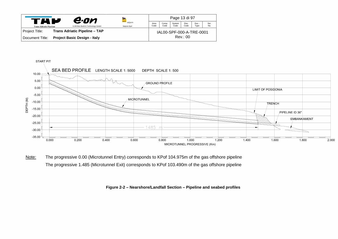
Note: The progressive 0.00 (Microtunnel Entry) corresponds to KPof 104.975m of the gas offshore pipeline
The progressive 1.485 (Microtunnel Exit) corresponds to KPof 103.490m of the gas offshore pipeline
Figure 2-2 – Nearshore/Landfall Section – Pipeline and seabed profiles

E.ON New Build & Technology GmbH
Saipem SpA
Page 14 di 97 Area Code
Comp. Code
System Code
Disc. Code
Doc.- Type
Ser. No.
Project Title: Trans Adriatic Pipeline – TAP IAL00-SPF-000-A-TRE-0001 Rev.: 00 Document Title: Project Basic Design - Italy
2.2 Onshore Section (From Landfall Microtunnel entry point to PRT)
2.2.1 Design data
The basic data assumed for the feasibility of the route are shown below in compliance with DM
17/04/2008.
• Type of gas pipeline: Type 1
• Design pressure (DP): 145 bar
• CPI (Fire Prev. Cert.) Pressure (MOP): 145 bar
• Utilization factor (f) adopted: 0.57
• Gas transported: Natural Gas
• Nominal pipeline diameter: DN 900 (36”)
• Internal diameter 871 mm
• Service easement area 20 + 20 m
• Material: Steel – Grade X65/450
• Wall Thickness: 26.8 mm
• Pipeline Length: 8.2 km
2.2.2 Block valve station
One BVS will be installed close to the pipeline landfall at KP 0.1 in order to enable the isolation of
the offshore pipeline from the onshore part for maintenance and safety purposes.
The block valve station is unmanned and contains as above ground features only a small cabinet
for power and control system and a fence to avoid any interference, covering a total surface area
of approximately 13 x 14 m (plus surrounding vegetation). The following figure illustrates the
foreseen BVS layout plan.

E.ON New Build & Technology GmbH
Saipem SpA
Page 15 di 97 Area Code
Comp. Code
System Code
Disc. Code
Doc.- Type
Ser. No.
Project Title: Trans Adriatic Pipeline – TAP IAL00-SPF-000-A-TRE-0001 Rev.: 00 Document Title: Project Basic Design - Italy
Figure 2-3 Plot of block valve station (source document: CBV00-ENT-100-F-DFT-0016)
The BVS will be remotely operated from a control centre in the PRT through a fibre-optic cable
communication system and will be connected to the local power grid. The pipeline the block valve
and by-pass valves as well as the connected piping will be buried below ground. Valve integrity is
also monitored by the pipeline Leak Detection System.
In coherence with the selection of the onshore line pipes, the selection of the tubes constituting
the block valve station is based on the same design standards and design specifications. The
diameter of these tubes will be 12” for the by-pass line and 2” for branches to measuring
instruments.
A permanent access road is foreseen, as shown in the Figure 2-4. Part of this access road will be
a new one (yellow line) part will be an enlargement of the existing road (green line).

E.ON New Build & Technology GmbH
Saipem SpA
Page 16 di 97 Area Code
Comp. Code
System Code
Disc. Code
Doc.- Type
Ser. No.
Project Title: Trans Adriatic Pipeline – TAP IAL00-SPF-000-A-TRE-0001 Rev.: 00 Document Title: Project Basic Design - Italy
Figure 2-4 Access Road to the BVS
2.2.3 Depth of burial of the pipeline
With regard to the construction methods of gas pipelines in Italy, Ministerial Decree 17/04/2008
prescribes a minimum pipeline cover not less than 0.9 m and 0.4 in rocky soil from the top of the
pipe. In any case gas pipelines in Italy are usually laid with a minimum cover of 1.5 m, in order to
provide the maximum guarantees of safety from possible interference with human activities
(excavating, ground-breaking for agricultural purposes etc.). The typical trench dimensions
respecting the legal requirements can be seen in following figure.

E.ON New Build & Technology GmbH
Saipem SpA
Page 17 di 97 Area Code
Comp. Code
System Code
Disc. Code
Doc.- Type
Ser. No.
Project Title: Trans Adriatic Pipeline – TAP IAL00-SPF-000-A-TRE-0001 Rev.: 00 Document Title: Project Basic Design - Italy
Figure 2-5 Typical onshore pipeline trench (source document: IPL00-ENT-100-F-DFT-0001)
2.2.4 Safety distances with respect to buildings
In accordance with Italian regulations no clusters of houses should be identified within a range of
100 m to the pipeline. In proximity to the planned pipeline route there are only very few single
houses, at a distance longer than 20 m (in compliance with the DM 17/4/2008).
2.2.5 Distances from power lines, parallelism and crossings with other utilities
In addition to the one provincial road and one minor asphalt road crossing by landfall microtunnel
upstream of KP 0 there is one more provincial road crossing at KP 6.5 and eight more minor
municipality road crossings. Details of all the asphalt road crossings and the proposed
construction method are provided in the table below.

E.ON New Build & Technology GmbH
Saipem SpA
Page 18 di 97 Area Code
Comp. Code
System Code
Disc. Code
Doc.- Type
Ser. No.
Project Title: Trans Adriatic Pipeline – TAP IAL00-SPF-000-A-TRE-0001 Rev.: 00 Document Title: Project Basic Design - Italy
Table 2-9: Crossings of the onshore pipeline
2.2.6 Corrosion protection
The onshore part of the pipeline system at the landfall in Italy consists of two parts:
• The station piping of Pipeline Receiving Terminal (PRT).
• The pipeline, with a length of 8.2 km, between Landfall and PRT.
Corrosion protection of the on-shore pipeline and station piping is first of all achieved by high
quality coatings. The table below lists the coating types as will be used in the TAP project
Application Factory coating Field coating Type Standard Type Standard
Product pipe in trench (open trench)
3LPE EN ISO 21809-1
Polymeric tapes ISO 21809-3
Product pipe inside casing and micro tunnel PUR ISO 21809-3 Casings
Product pipe installed by ramming (pipe jacking), auger boring (open front drilling) or horizontal directional drilling (HDD).
3LPP (for ambient temperature > 0 ºC)
EN ISO 21809-1 Glass fibre reinforced epoxy (EP-GFRP = epoxy resin with glass fibre reinforcement)
ISO 21809-3 3LPE and Gf-UP (glass fibre reinforced, unsaturated
EN ISO 21809-1 / ISO 21809-3 (TAP specification)
Chainage [m]
1 Provincial road SP366 -500** Puglia /Lecce MelendugnoLandfall micro-
tunnel
2 Municipal road name unknown 0 Puglia /Lecce MelendugnoLandfall micro-
tunnel
3 Municipal road Strada comunale S. Viceta 601 Puglia /Lecce Melendugno Open cut
4 Municipal road Strada comunale S. Viceta 1.131 Puglia /Lecce Melendugno Open cut
5 Municipal road Strada comunale S. Viceta 2.027 Puglia /Lecce Melendugno Open cut
6 Municipal road Strada comunale S. Viceta 4.012 Puglia /Lecce Melendugno Open cut
7 Municipal road Strada comunale S. Niceta 4.620 Puglia /Lecce Melendugno Open cut
8 Municipal road name unknown 5.611 Puglia /Lecce Melendugno Open cut
9 Municipal road name unknown 5.906 Puglia /Lecce Melendugno Open cut
10 Provincial road SP2 Strada prov. Lecce-Melendugno 6.452 Puglia /Lecce Melendugno Trenchless
11 Municipal road name unknown 7.602 Puglia /Lecce Melendugno Open cut
MunicipalityCrossing MethodWGS84 / UTM 34NNo Region / ProvinceType Name

E.ON New Build & Technology GmbH
Saipem SpA
Page 19 di 97 Area Code
Comp. Code
System Code
Disc. Code
Doc.- Type
Ser. No.
Project Title: Trans Adriatic Pipeline – TAP IAL00-SPF-000-A-TRE-0001 Rev.: 00 Document Title: Project Basic Design - Italy
polyester resins) layer
For all components which – due to their geometric form – cannot be coated like a pipeline: for valves, fittings, T pieces, etc
PUR EN 10290 PUR EN 10290
Air to ground transitions 3LPE EN ISO 21809-1 PUR or
3LPE + EP-GFRP EN 10290
PUR EN 10290 As above Internal pipe wall (to reduce friction for flow of gas) Epoxy resin EN 10301 - -
Table 2-10: Onshore pipeline coating specifications
To prevent corrosion at coating defects of the pipeline, a cathodic protection system will be
installed. The cathodic protection system will consist of:
• A DC rectifier, incl. an anode bed, for impressing current to the pipeline
• Test posts for regularly checking of the system performance
Pipelines inside the PRT will be in electrical contact with stations groundings and station
foundations. For several reasons, like safety which require grounding of metal objects in
hazardous areas, it will not be possible to eliminate these electrical contacts
In order to achieve protection under these circumstances, a so-called local cathodic protection
system will have to be installed. A local cathodic protection system is aiming at achieving
sufficient soil-to-pipe potentials by changing (relative to remote earth) the soil side of the
potentials.
A local cathodic protection system will consist of:
• Isolating material at surfaces of foundations with reinforced concrete. The isolating material is needed to uphold the relative positive soil potentials in the vicinity of the pipeline.
• A transformer/ rectifier to impress current to the anodes distributed throughout the terminal.
• Single anode controls, in combination with distribution boxes, to prevent that the local cathodic protection system will cause corrosion interaction with other objects in the vicinity of the terminal.

E.ON New Build & Technology GmbH
Saipem SpA
Page 20 di 97 Area Code
Comp. Code
System Code
Disc. Code
Doc.- Type
Ser. No.
Project Title: Trans Adriatic Pipeline – TAP IAL00-SPF-000-A-TRE-0001 Rev.: 00 Document Title: Project Basic Design - Italy
2.3 Pipeline Receiving Terminal (PRT)
2.3.1 Technical data
The Pipeline Receiving Terminal is required to control the flow of the gas delivered into the Snam
Rete Network. The upstream pipeline is designed for a pressure of 145 bar (g) and the
downstream pipeline is designed for a pressure of 75 bar (g).
The main design conditions are the following:
• Design pressure up to pressure reduction: 145 bar (g);
• Design pressure downstream pressure reduction: 75 bar (g);
• Supply pressure at SRG network: 75 bar (g) max;
• Pipeline transportation capacity at first design stage: 10 Bcm/y
• Design flow rate for the first design stage: 1,320,000 Sm³/h;
• Nominal flow rate for the first design stage: 1,190,000 Sm3/h
• Pipeline transportation capacity at final design stage: 20 Bcm/y
• Design flow rate for the final design stage: 2,640,000 Sm³/h;
• Nominal flow rate for the final design stage: 2,380,000 Sm3/h
• Minimum supply temperature at SRG network: 3 °C.
Pipeline Receiving Terminal will include:
• Filter package at inlet;
• Flow and pressure control valves;
• Gas heating equipment;
• Utility, such as instrument air, fuel gas supply, diesel power generation, fire fighting equipment, condensate tank, heating system;
• PIG trap station;
• Fiscal metering (USM) with redundancy;
• 2 vent stacks
• Supervisory control center for the entire Greece-Albania-Italy pipeline.
E.ON New Build & Technology GmbH
Saipem SpA
Page 21 di 97 Area Code
Comp. Code
System Code
Disc. Code
Doc.- Type
Ser. No.
Project Title: Trans Adriatic Pipeline – TAP IAL00-SPF-000-A-TRE-0001 Rev.: 00 Document Title: Project Basic Design - Italy
2.3.2 Location of the Station
The PRT will be installed within the border of the Municipality of Melendugno, approximately 8 km
inland from the seashore. The connection to the SNAM Rete Gas (SRG) network will be at the
fence of the PRT.
2.3.3 Process description and functions
The maximum gas flow design rate of TAP Terminal is 10 Bcm/year for initial installed equipment.
The capacity increasing to 20 Bcm/year will be done by adding additional equipment (pumps,
heaters, entire trains etc.). The purpose of the gas metering station is to perform fiscal
measurement of the quantity and quality of gas to be delivered from TAP Terminal to SRG
Network.
The purpose of the terminal inlet section is to receive the incoming gas feed and to act a point of
isolation (and emergency shutdown by means of ESD valves) between the BVS close to the
coast and the Terminal. The inlet facilities also contain a Pig Receiver.
For availability reasons the terminal will be provided in a block design for the different process
units (filter, two electrical heaters and two gas fired boilers, heat exchangers, pressure/flow
control and metering) with 3 identical gas processing units each fed from a single header
immediately downstream of the terminal inlet facilities. Between each process unit the gas will be
again collected in a common header and then again split up to the next process unit.
The first process unit consist of filter separators which remove potential solids and liquids from
the gas stream before the gas enters the conditioning facilities (heater, pressure/flow control
unit). Liquids will be collected in this process unit and further fed into the closed drain system
which leads to a condensate tank.
The heating of the gas to be received shall be done to guarantee the minimum delivery gas
temperature, downstream the pressure reducing system; this operation may be required only in
transport transient condition (packing/depacking operation, start-up etc.) and in case of quick
fluctuation of the pressure in the downstream SRG network. The gas heating will be done by heat
exchangers, based on hot water circulation. Hot water shall be supplied by a closed circuit
production system using electrical heaters and gas fired boilers. The heating system is designed

E.ON New Build & Technology GmbH
Saipem SpA
Page 22 di 97 Area Code
Comp. Code
System Code
Disc. Code
Doc.- Type
Ser. No.
Project Title: Trans Adriatic Pipeline – TAP IAL00-SPF-000-A-TRE-0001 Rev.: 00 Document Title: Project Basic Design - Italy
to provide in total 8.6 MW duty. The electrical heaters which are designed to provide a duty of
approximately 2 MW, will cover most of the operational heating requirements. The gas fired
boilers, designed for the remaining duty, are intended to cover mainly start-up and abnormal
operation conditions. Thus, local air emissions from heating will be sporadic.
In order to protect downstream equipment and systems against over-pressure (145 barg vs. 75
barg) a pressure/flow control unit controls the flow rate to the downstream network and
simultaneous reduces the pressure to the downstream network pressure. Additionally a HIPPS
(High Integrity Pressure Protection System) shall be installed between pressure/flow control unit
and metering unit. This system consists of two serial mounted independent quick self-closing
valves (one is purely mechanical, the second one is an instrumented safety system), which are
maintained open as long as the downstream pressure is below the set point.
The quantity of the natural gas to Snam Rete network will have to be measured for custody
purposes. This will be done by using ultrasonic flow meters (USM). To fulfil the strict
requirements of custody transfer measurement two identical USM will be installed in serial, in
each meter run to compare the accuracy of the individual meter. The quality of the natural gas to
SRG network will be analyzed for custody purpose by a Gas Analysing Unit.
A fuel gas unit will be provided for the conditioning of the fuel gas to the requirements of the
heating medium. The fuel gas is taken from the outlet side of the pipeline receiving terminal as
the lowest pressure level is expected there. As the fuel gas might be also taken during terminal
shut down from Snam Rete Network the fuel gas stream will be measured with a flow meter
suitable working a measurement required for invoicing.
The closed drain system will be collected in a suitable condensate tank, 10 cubic metres in
volume. The closed drain system will be sized for the final TAP Terminal flow rate (20 Bcm/year),
considering the quantity of liquids discharged from Main Gas filters, and the hypothesis that a
liquid slug can enter the Terminal. The collected fluid shall be removed by road tanker.
For surface/rain water two separate drainage systems are required for the TAP Terminal:
• Process areas
• Other areas (utilities, buildings etc.)

E.ON New Build & Technology GmbH
Saipem SpA
Page 23 di 97 Area Code
Comp. Code
System Code
Disc. Code
Doc.- Type
Ser. No.
Project Title: Trans Adriatic Pipeline – TAP IAL00-SPF-000-A-TRE-0001 Rev.: 00 Document Title: Project Basic Design - Italy
Their purpose is to collect and discharge the applicable waste water preferably to the public
waste water network.
Surface water from potential polluted areas will be carried to an oil separator and then into the
sewage system. This sewage system will also be used for the discharge of sanitary waste water.
Instrument and plant air systems are designed to supply approx. 200 Sm3/h, at 12.5 to 15 barg
pressure of dried air to the instrument and plant air distribution. The air compressors are operated
such that the duty compressor auto starts/stops as required.
The depressurization of the station piping/equipment, both in emergency and in maintenance
condition, will happen through two dedicated vent stacks, to be installed in a fenced area within
TAP Terminal. The cold vent stacks are designed to blow down the terminal piping and
equipment. The onshore pipeline section can be depressurised via the PRT (mobile vent
connection at the pig receiving area) or by line packing of the neighbouring sections to avoid local
emission; the offshore pipeline is foreseen, if necessary, to be de-pressurized at the compressor
station in Albania. The vent stacks are designed to blow down the entire volume between the
inlet- and outlet ESD valves from design pressure (145 barg) to 6.9 barg within approximately 15
min. Gas dispersion as well as heat radiation levels have been evaluated as per the requirements
of EN 23251. According to radiation calculations, the vent stack height will be 10 m, with a sterile
area radius of 86 m where a heat load of 5 kW/m² could occur.
The main tank of diesel oil with a capacity of 16 m3 is designed to feed diesel fuel to both the
emergency generator daily tank and the firewater emergency pump daily tank.
The diesel oil will be supplied to the TAP Terminal by road tankers.
The potable water system is intended to provide potable water to the buildings expected to be in
the TAP Terminal (such as Workshop/Storage Building and Administration Building), to satisfy
personnel needs.
The system will be fed from existing water network via a dedicated supply line or from a new well
on the station site or nearby.
The service water system shall supply service water to:
• the various plant areas of the Terminal, for general purposes and to satisfy the equipment washout needs,
• the Fire Extinguishing Water Tank (aboveground).

E.ON New Build & Technology GmbH
Saipem SpA
Page 24 di 97 Area Code
Comp. Code
System Code
Disc. Code
Doc.- Type
Ser. No.
Project Title: Trans Adriatic Pipeline – TAP IAL00-SPF-000-A-TRE-0001 Rev.: 00 Document Title: Project Basic Design - Italy
The fire water system will be sized according to Italian standard UNI EN 10779 for industrial
areas (192 m3/hour over a guaranteed period of 2 hours, plus 50 m3 buffer) and has to be
evaluated with local fire brigade. The fire water system will have a stored volume of roughly 450
m³. The fire water tank is always on line. Filling of the fire water cistern is a manually controlled
operation.
2.3.4 Mechanical equipment
2.3.4.1 Design Parameters (Process Requirements)
The main piping and fittings of the PRT station are categorized into two main sections. In the inlet
area, the piping and fittings will be designed for a maximum pressure of 145 barg and a
maximum temperature of 65 up to 100°C. On the outlet side of the PRT station the piping and
fittings are to be designed for a maximum operating pressure of 75 barg and a maximum
temperature of 65°C.
The particular maximum quantity to be transported in the individual piping sections, and a flow
speed of approx. 15 m/s was used as the basis for determining the nominal diameters.
The underground pipes are designed with an earth cover of 1m. The aboveground pipes are laid
close to the ground level, to facilitate the maintenance of the valves and equipment.
The pipes calculation is carried out according to EN 1594 for primarily static stress. Pipe fittings
examined as reducers, tees, flanges and branches are calculated according to the relevant PED
instructions.
2.3.4.2 Piping design
The piping will be designed according to the project pipe classes.
All necessary supports, pipe guides and fixed points are to be determined on the basis of the
requirements of the strength calculations and the calculations of the static equilibrium for the
piping.

E.ON New Build & Technology GmbH
Saipem SpA
Page 25 di 97 Area Code
Comp. Code
System Code
Disc. Code
Doc.- Type
Ser. No.
Project Title: Trans Adriatic Pipeline – TAP IAL00-SPF-000-A-TRE-0001 Rev.: 00 Document Title: Project Basic Design - Italy
2.3.4.3 Acceptance and testing
All piping to be installed within the station is to be manufactured, tested, and accepted according
to the valid EN 1594 and PED worksheets.
2.3.4.4 Strength and leakage tests
After completion of the piping system, a strength test is to be carried out on the components or
individual piping sections.
The strength test is to be performed as hydro-test (water based) according to the EN 1594
worksheet.
After completion of the entire piping system, leak tests are to be carried out with nitrogen.
2.3.4.5 Tests of welds
The welded connections are to be tested according to EN ISO 17635. All welded seams are to be
100% tested according to the TAP / E.ON standard.
All connection seams are to be produced as golden welds. The testing of welded seams is to be
performed using ultrasonic and X-ray tests.
2.3.4.6 Coating, Corrosion Protection
Piping and plant components are situated above ground to be protected against external
corrosion by coating, reference is made to section 2.2.6.
Coating of piping laid underground and coatings performed on the construction site are to be
carried out according to national and international guidelines.
2.3.4.7 Acoustic and thermal Insulation
Equipment and piping will be insulated for the purposes of heat conservation, maintenances
process of stabilized temperatures during atmospheric temperature changes, condensation
presentation and burn presentation of personnel.
The acoustic insulation includes the entire piping system situated above ground, as well as any
fittings or processing equipment.
The implementation of the acoustic insulation is to be carried out on the basis of the noise study.

E.ON New Build & Technology GmbH
Saipem SpA
Page 26 di 97 Area Code
Comp. Code
System Code
Disc. Code
Doc.- Type
Ser. No.
Project Title: Trans Adriatic Pipeline – TAP IAL00-SPF-000-A-TRE-0001 Rev.: 00 Document Title: Project Basic Design - Italy
2.3.4.8 Pipe Stress Analysis
A pipe stress analysis will be accomplished for all new pipe systems. Within the scope of this pipe
stress analysis (PSA) there will be calculated the maximum allowable stress as well for every
single component and the nozzle loads from equipment. Based on the PSA the foundations as
well as support loads are determined. These loads will be transferred to the civil division.
After the PSA the pulsation study will be prepared.
2.3.5 Control system
The TAP control system will permit full operational monitoring and control of the terminal.
Moreover, inside the PRT the control and supervision centre of the entire pipeline will be located.
Detailed operating procedures for the pipeline control system will be developed. These
procedures will be in place ahead of pipeline operation. The operating procedures will typically
address the following:
• An administrative system covering legal considerations, work control and safety;
• Clear and effective emergency procedures and operating instructions;
• Adequate and regular training of all personnel involved in operational and maintenance issues;
• A comprehensive system for monitoring, recording and continually evaluating the condition of the pipeline and associated equipment;
• A system to control all development or work in the vicinity of the pipeline;
• Effective corrosion control and monitoring;
• A system to collect and collate information on third party activities; and
• Monitoring of restoration, and the undertaking of remedial work as necessary.
The pipeline including the entire offshore part between Albania and Italy will be monitored and
controlled 24 hours a day and 365 days a year from a central control room. The monitoring
system is a SCADA System (System Control and Data Acquisition), during operation, leak
detection will be by continuous measurements of pressure and flow rates at the inlet and outlet of
the stations and pipeline. If a leak is detected, an alarm is triggered. To allow internal inspection,
pigging facilities will be installed. The pipeline system has been designed to allow use of
instrumented pigs.
E.ON New Build & Technology GmbH
Saipem SpA
Page 27 di 97 Area Code
Comp. Code
System Code
Disc. Code
Doc.- Type
Ser. No.
Project Title: Trans Adriatic Pipeline – TAP IAL00-SPF-000-A-TRE-0001 Rev.: 00 Document Title: Project Basic Design - Italy
2.3.6 SCADA and Communication Systems
2.3.6.1 SCADA
The Supervisory Control and Data Acquisition System is a backend system that has overall
control of the pipeline and station operation. It is one of the main instance regarding core
business aspects. It comprises a series of control and acquisition functions that include, amongst
others, the
• Transport operation (monitoring, process insight, alarms, thresholds, etc.)
• Overall pipeline security including all BVS and tie-in valves of each station
• Overall pipeline Ordered Shutdown triggering
• Logging
• Simulation
• Engineering
• Etc.
The SCADA system will be placed in the Supervisory Control Center and be backed up with a
Backup Supervisory Control Center. The BSCC will take over in failed attempts of use the SCC.
SCADA heavily relies on the communication infrastructure alongside the pipeline, the so called
Passive and Active Optical Network (PON/AON).
2.3.6.2 LDS
The Leak Detection System shall eliminate the threat of undetected and unwanted
depressurization of parts or the entire pipeline. It monitors by technical means the status of the
pipeline and warns or acts in case of imminent danger to the pipeline itself or the business (loss
of gas). A mechanism will be implemented relying on sensors along the pipeline to detect
malfunctions. A certain level of automation can be achieved to prevent losses and danger to
human life. The LDS will report to the SCADA system.
2.3.6.3 PON
The Passive Optical Network is the physical transport layer of the communication backbone. It
serves as the carrier for the numerous systems with communication needs. Infrastructure-wise
optical distribution frames will offer the possibility to implement various systems for wide area
network connections. It comprises a number of fiber optical cables, installed along the entire

E.ON New Build & Technology GmbH
Saipem SpA
Page 28 di 97 Area Code
Comp. Code
System Code
Disc. Code
Doc.- Type
Ser. No.
Project Title: Trans Adriatic Pipeline – TAP IAL00-SPF-000-A-TRE-0001 Rev.: 00 Document Title: Project Basic Design - Italy
pipeline. Spare capacities for future expansions or third party business (like bright/dark fiber
interconnections for telcos or data carriers) can be allocated.
2.3.6.4 AON
The Active Optical Network is the actual communication backbone. It features a setup of different
channels, protocols and capacities to allow flexible interconnection of all relevant systems.
Distances of up to one hundred (100) kilometers per hop can be spanned. By making the AON
available in all stations and block valve stations various services can be delivered to any point in
the ring, like telephony, video conferencing, data access, remote control, etc. It is also able to
deliver redundancy.
2.3.7 Alerting Systems and Monitoring
2.3.7.1 Gas detection System (GDS)
The Gas Detection System detects gas leakages on the station inside the fuelgas building as well
as in the open range, e.g. gas heaters, metering piping and other above ground piping within the
station limits. One warning and one alarm can be caused by the GDS, the detection of 20% and
40% lower explosion limit in the proximity of its sensors. The GDS reports to the station’s ESD
system as well as to the station’s DCS and to the SCADA system.
2.3.7.2 FDS
The Fire Detection System detects smoke and fires within the station buildings, inside the fuelgas
building and in the open range, e.g. gas heaters, metering piping and other above ground piping
within the station limits. One warning and one alarm can be caused by the FDS, a fire warning
and a fire alarm. The FDS reports to the station’s ESD system as well as to the station’s DCS and
to the SCADA system.
2.3.7.3 AVAS
The Audio Visual Alerting System generates an audible and visible alert notification, distributed
across the entire station. It serves as evacuation alert to all personnel in hazardous or potentially
hazardous areas. The AVAS is triggered by the FDS, GDS or manually in case of gas, fire or any
other situation deemed hazardous. Among others it reports into the SCADA system.

E.ON New Build & Technology GmbH
Saipem SpA
Page 29 di 97 Area Code
Comp. Code
System Code
Disc. Code
Doc.- Type
Ser. No.
Project Title: Trans Adriatic Pipeline – TAP IAL00-SPF-000-A-TRE-0001 Rev.: 00 Document Title: Project Basic Design - Italy
2.3.8 Security Systems
2.3.8.1 CCTV
The Closed Circuit TeleVision System comprises a set of (nightvision) cameras placed within the
station’s fence and spans a surveillance perimeter around each station or object. Virtual fencing
enables the system to automatically display trespassers or intruders violating a certain area
around the station. It can be coupled with the SCADA system to generate alarms while a station
is unmanned.
2.3.8.2 ACS
The Access Control System provides security measures and their administration to the station’s
personnel. Electronic badges enable employees or guests to open doors, gates, barriers or gain
access to the SCADA or station control system. Also evacuation purposes are served by tracking
the presence of employees or guests within the station limits. The ACS reports to the SCADA
system.
2.3.9 Power supply and electrical components
Power requirements of the pipeline receiving terminal (PRT) will be met by a medium Voltage
electricity transmission line and substation which will connect the installations with medium
voltage network in the station area. For back-up power supply diesel engine driven power
generators are provided.
The following electrical systems will be installed:
• Transformers
• Medium voltage switchgear;
• Low voltage switchgear;
• Emergency power supply with diesel generators;
• Uninterruptible power supply;
• Grounding and lightning protection;
• Building installations;
• Outdoor lighting.
E.ON New Build & Technology GmbH
Saipem SpA
Page 30 di 97 Area Code
Comp. Code
System Code
Disc. Code
Doc.- Type
Ser. No.
Project Title: Trans Adriatic Pipeline – TAP IAL00-SPF-000-A-TRE-0001 Rev.: 00 Document Title: Project Basic Design - Italy
PRT station will contain electrical circuits with the following voltages:
• Medium voltage three phase AC system;
• 400V three phase AC system (main power system);
• 400 V three phase AC emergency power system;
• 230 V single phase AC UPS system;
• 110 V DC UPS system;
• 24 V DC UPS system.
SCC will contain electrical circuits with the following voltages:
• Line in medium voltage network or 400 V grid operator
• 400V three phase AC system with diesel emergency generator (main power system);
• 230 V single phase AC UPS system;
• 24 V DC UPS system.
The electricity furniture will be done via the public grid and supported by emergency power supply
and backup provisions.
2.3.10 Civil design and architecture
2.3.10.1 General
The architectural concept was elaborated with the aim to avoid the station being identified as an
industrial plant. Contrary to typical industrial design, the design concept will incorporate design
elements of higher aesthetic quality, making references to traditional residential typologies.
In the Salento area there are very diffused characteristic settlements named “Masserie”, two-
storeys regtangular plan buildings surrounded by productive single storey buildings.Other typical
rural buildings in the region are the “Pagghiare” and a very well preserved example is within PRT
site.
The main station buildings are arranged to immitate a sort of Masseria settlement with an organic
layout that limits the number of buildings. A sort of “dialogue” between new main buildings and
existing “Pagghiara” could be initiated by their positioning. The same “dialogic” approach will be
followed for materials choice, by alternating plaster and stone for buildings facades.

E.ON New Build & Technology GmbH
Saipem SpA
Page 31 di 97 Area Code
Comp. Code
System Code
Disc. Code
Doc.- Type
Ser. No.
Project Title: Trans Adriatic Pipeline – TAP IAL00-SPF-000-A-TRE-0001 Rev.: 00 Document Title: Project Basic Design - Italy
This architectural concept involving the stringent selection of materials and colours as well as the
definition of a high standard of workmanship are the basis of the design. The projected and
recessed façade elements which are emphasized by the produced shading are also a central part
of the architectural concept. The intention is to adapt the station design within its surroundings
and provide technically modern, bright workplaces in a comfortable atmosphere. Colours,
materials, shape of buildings and facades will be adapted to the existing rural buildings in the
area.
E.ON New Build & Technology GmbH
Saipem SpA
Page 32 di 97 Area Code
Comp. Code
System Code
Disc. Code
Doc.- Type
Ser. No.
Project Title: Trans Adriatic Pipeline – TAP IAL00-SPF-000-A-TRE-0001 Rev.: 00 Document Title: Project Basic Design - Italy
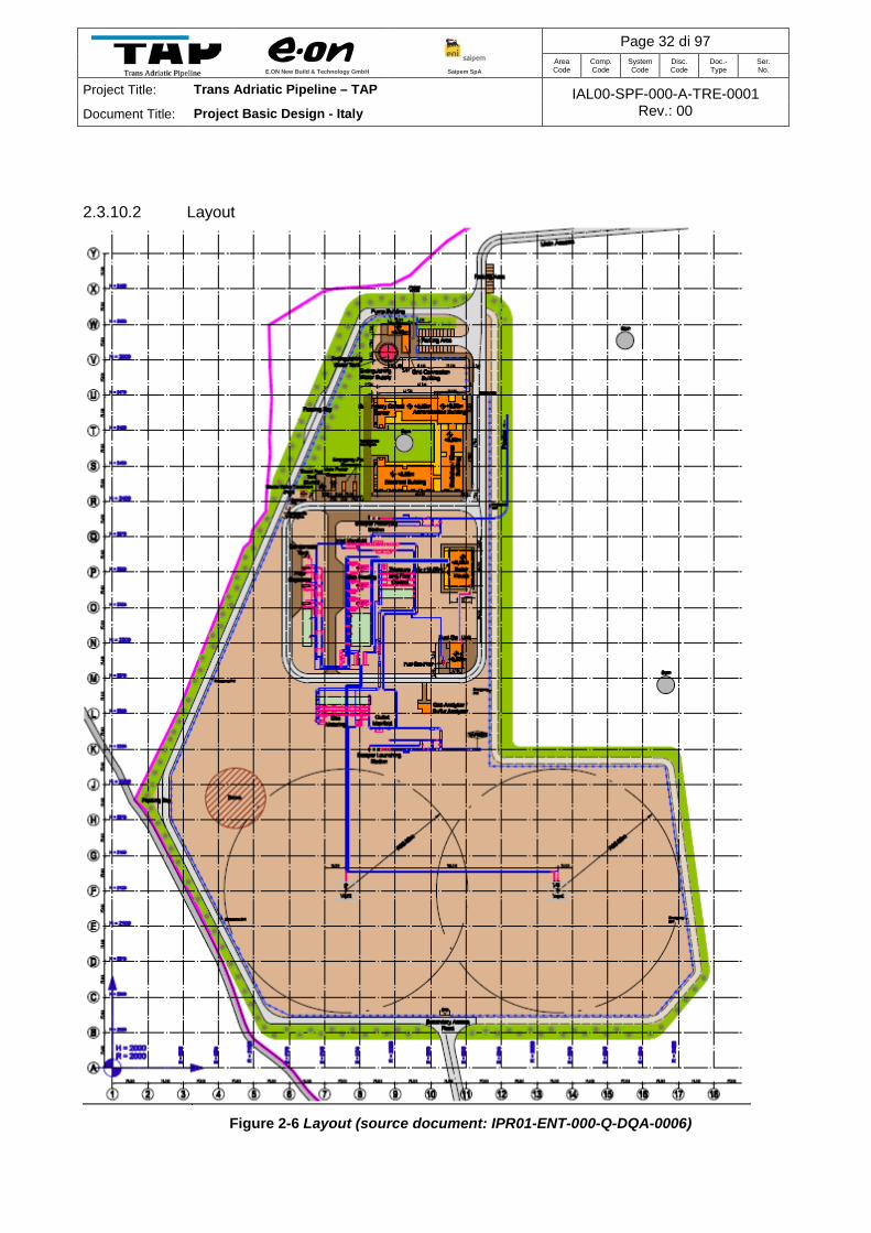
2.3.10.2 Layout
Figure 2-6 Layout (source document: IPR01-ENT-000-Q-DQA-0006)

E.ON New Build & Technology GmbH
Saipem SpA
Page 33 di 97 Area Code
Comp. Code
System Code
Disc. Code
Doc.- Type
Ser. No.
Project Title: Trans Adriatic Pipeline – TAP IAL00-SPF-000-A-TRE-0001 Rev.: 00 Document Title: Project Basic Design - Italy
PRT dimension, with reference to fenced area including the surrounding path, is 12 hectares
approximately. The plant layout could be slightly updated during the next detailed design phases,
but will in any case be inside the construction yard location.
2.3.10.3 Site location and landscaping
The PRT site is a flat and uncultivated field bordered to South-West by a partially asphalted
“vicinale” road that links the town of Vernole to Calimera road. To North, to West and to East the
site is bordered by olive-tree cultivated fields and to South by an almost flat uncultivated field.
The area is characterized by land division created by a network of dry stone walls. The PRT site
in the West, North and East is also bordered by existing dry stone walls in alternating heights. A
periphery fence will be erected at a suitable distance from the original dry walls. This area could
be used for landscaping with planting and walkways. The surrounding path at the west side of the
station shall be used as a secondary station access simultaneously.
Due to the landscaping a Landscape Impact Mitigation Report will be carried out separately.
2.3.10.4 Building and structures
To lower the visual impact the amount and height of buildings and structures will be minimized.
Roofs were designed as flat roofs, indigenous to this region.
All buildings will be single-storey buildings. Due to the outsourcing of some storage capacity and
maintenance works (e.g. for huge and heavy valves) the Workshop and Storage Building will not
be fitted with a crane, thus the height could be reduced to 5.50 m.
2.3.10.5 Height of buildings
Height of building will not exceed:
Supervisory Control Center/ Electrical Building/
Fuel Gas Skid/Sunshade for parking area/
Workshop/Stores/Staff Building 5.5 m
Administration/Building 6.0 m
Boiler House: 8.0 m
Vents/Stacks: 10.0 m

E.ON New Build & Technology GmbH
Saipem SpA
Page 34 di 97 Area Code
Comp. Code
System Code
Disc. Code
Doc.- Type
Ser. No.
Project Title: Trans Adriatic Pipeline – TAP IAL00-SPF-000-A-TRE-0001 Rev.: 00 Document Title: Project Basic Design - Italy
Pipe bridges and cable bridges have been omitted to avoid an industrial image of the plant.
Great care will be taken in the architectural form of the buildings and their facades to ensure the
adaption of the design within its surroundings.
Landscaping and plantation between and in front of the buildings could supplement this aim.
2.3.10.6 Colours
The colours of the station design will be adapted to the surrounding natural colours of the existing
landscape. i.e.:
• Sandstone masonry or sand coloured facades as presented by the surrounding dry walls and also for buildings in the region
• Colour of the piping
• Colour of the sealing of station area outside of buildings and ,the colour of the vents are dependent on the results/proposals of the Landscape Impact Mitigation Report
Stacks will be visually integrated in the boiler house volume in order to minimize “industrial”
characteristics.

E.ON New Build & Technology GmbH
Saipem SpA
Page 35 di 97 Area Code
Comp. Code
System Code
Disc. Code
Doc.- Type
Ser. No.
Project Title: Trans Adriatic Pipeline – TAP IAL00-SPF-000-A-TRE-0001 Rev.: 00 Document Title: Project Basic Design - Italy
3 ROUTE SELECTION CRITERIA
3.1 Offshore Section
The selected route will be obtained by the best satisfaction of the following requirements:
A. to reduce the length (in order to reduce the line pipe quantity);
B. to minimise interference with seabottom scars and other seabed features, i.e. geological constraints;
C. to have a minimum number of curves;
D. to have a maximum and possibly stable route radius for each curve (the curve stability could be a special item in areas of potential clayey soils);
E. To minimise the pipeline installation and construction constraints, i.e. obstacles, fishing areas, dumping areas, UXO areas, archaeological areas;
F. to optimise the crossings with other pipelines and cables, i.e. to use a crossing direction as close as possible to the normal one with respect to the routes to be crossed, mainly aiming at reducing the crossing lengths (due to real congested area, it is expected a governing requirement);
G. to minimise interferences with navigation channels;
H. to identify the widest installation corridor in the most critical and uneven areas;
I. to minimise the number, the lengths and the heights of the free spans in the most uneven areas. The number of points with local bend concentration shall be minimised and, if not completely avoided, the relevant stress level has to be minimised;
J. to optimise the pipeline freespan scenario within areas of seabed erosion (it is expected a typical item in the areas where sandy/sediment soil is expected;
K. to optimise the lay away from the landfall;
L. to comply with any 3rd Party and Authority requirements;
M. to minimise environmental impacts.
3.2 Onshore Section
The following general design criteria have been observed for the selection of the onshore pipeline
route:

E.ON New Build & Technology GmbH
Saipem SpA
Page 36 di 97 Area Code
Comp. Code
System Code
Disc. Code
Doc.- Type
Ser. No.
Project Title: Trans Adriatic Pipeline – TAP IAL00-SPF-000-A-TRE-0001 Rev.: 00 Document Title: Project Basic Design - Italy
A. to check the route as regards the possibility of restoring the crossed areas, returning them to the morphological conditions and land use existing before the works, thereby minimizing the impact on the territory;
B. to transit, as far as possible, in agricultural areas, avoiding crossings in areas affected by urban and/or industrial development plans;
C. to avoid areas susceptible to hydrogeological instability;
D. to avoid the buffer areas of the springs and wells tapped for drinking water;
E. to avoid, wherever possible, marshlands and peat soil;
F. to reduce to a minimum the restrictions brought about by gas pipeline easements on private property by using, wherever possible, the easement corridors already constructed by other pre-existing infrastructure (natural gas pipelines, channels, roads etc.);
G. to guarantee to the personnel assigned to operation and maintenance of the pipeline the possibility to access under safe conditions.
The pipeline route has, therefore, been checked and defined after a detailed examination of the
aforementioned aspects and on the basis of the results of on-site inspections and surveys carried
out in the area of interest.
In this sense, analyses and studies have been carried out on all the various situations, of both
natural and anthropic origins, that could create criticalities both for the construction and for the
subsequent management of the work as well as for the environment in which the work is situated,
examining, evaluating and comparing the various possible design solutions from the standpoint of
public health, environmental protection, assembling techniques, and time frames required for
implementation and environmental restoration.
In detail, the route optimisation has been carried out after the completion of the following
operations:
• acquisition of the geographical maps in order to classify the lithotypes present along the chosen route and identify any sensitive areas;
• acquisition of thematic maps and data on environmental characteristics (e.g. vegetation, fauna, land use etc.);
• retrieval of documentation regarding restrictions (environmental, archaeological etc.) in order to identify protected areas;
• acquisition of Municipality Plan of the municipality intersected in order to delimit the expansion areas;
E.ON New Build & Technology GmbH
Saipem SpA
Page 37 di 97 Area Code
Comp. Code
System Code
Disc. Code
Doc.- Type
Ser. No.
Project Title: Trans Adriatic Pipeline – TAP IAL00-SPF-000-A-TRE-0001 Rev.: 00 Document Title: Project Basic Design - Italy
• retrieval of information concerning potential future public works (roads, railways, catchment basins etc.);
• information and preliminary checks with Local Authorities (e.g.: Municipality);
• specialist surveys along the route (special crossings, critical areas etc.).
In particular, the exploration of the route provided the opportunity to carry out the required checks
on:
• the geometry of the route;
• the geological and geomorphological conditions of the route;
• the definition of any special works (e.g. "trenchless” solutions);
• the presence of water table (as far as possible).
4 PIPELINE ROUTE DESCRIPTION
4.1 Offshore, Nearshore and Landfall Sections
The pipeline enters the Italian jurisdiction territory in the middle of the straits of Otranto, about 45
km from the Italian coast (KPof 60.14) and reach the territorial waters around KPof 80.63 of the
offshore pipeline (see Figure 4-1).
The nearshore section starts from approx. KPof 100.40.
At about 95m water depth, the almost straight route is slightly deviated southwest by means of an
3000 m radius, in order to approach the Italian coast following a rectilinear alignment
perpendicular to the shoreline.
The final section of the route, approximately 3.600 m long, is straight and crosses a quite gentle
slope up to reach a narrow calcarenite beach located in an area North of San Foca village
(comune of Melendugno), (see Figure 4-2).
The rectilinear section in the proximity of the coast is needed for the installation of the pipeline
inside the landfall tunnel by means of a pull-in method.

E.ON New Build & Technology GmbH
Saipem SpA
Page 38 di 97 Area Code
Comp. Code
System Code
Disc. Code
Doc.- Type
Ser. No.
Project Title: Trans Adriatic Pipeline – TAP IAL00-SPF-000-A-TRE-0001 Rev.: 00 Document Title: Project Basic Design - Italy
Figure 4-1 – Selected Offshore Route
The soil in the nearshore and landfall area is characterized by the presence of calcarenite also
known as “dune rock” or “dune limestone”. It is a rock formed by the percolation of water through
a mixture of calcareous shell fragments and quartz sand causing the dissolved lime to cement the
mass together.

E.ON New Build & Technology GmbH
Saipem SpA
Page 39 di 97 Area Code
Comp. Code
System Code
Disc. Code
Doc.- Type
Ser. No.
Project Title: Trans Adriatic Pipeline – TAP IAL00-SPF-000-A-TRE-0001 Rev.: 00 Document Title: Project Basic Design - Italy
Figure 4-2 – Selected Route in the Nearshore Area
Given the features of the affected coastal area, the most appropriate solution is by means of a
trenchless technique. The narrow beaches and a road running along the coast do not offer
sufficient space for an “open trench” method.

E.ON New Build & Technology GmbH
Saipem SpA
Page 40 di 97 Area Code
Comp. Code
System Code
Disc. Code
Doc.- Type
Ser. No.
Project Title: Trans Adriatic Pipeline – TAP IAL00-SPF-000-A-TRE-0001 Rev.: 00 Document Title: Project Basic Design - Italy
The selection of the landfall microtunnel solution aims at minimizing the impacts of the
construction works on the shore and in the nearshore areas allowing to avoid environmental
sensitive areas (presence on the seabed of sparse vegetation of Posidonia oceanica).
The tunnel entry point, about 617 m far from the shore line, has been located taking into account
the environmental constraints of the area, and is very suitable for the location of the working area.
4.2 Onshore Section
As described in section 4.1 the pipeline landfall will be implemented by means of a microtunnel
underneath the coastline and the Provincial Road SP366 between San Foca and Torre Specchia
Ruggeri. Also a minor asphalt road is crossed by this landfall tunnel. The tie-in with the onshore
pipeline at the end of this tunnel marks the KP 0 of the onshore route and will be located
approximately 600 m off the coast (direction south-west). A block valve station is planned to be
erected just downstream of this tie-in point.
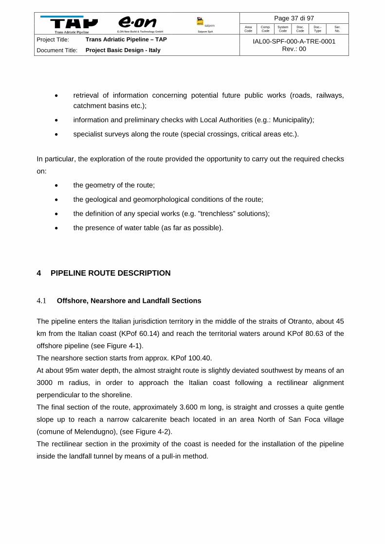
The planned pipeline route passes in the south of a large topographical depression consisting of
a wetland named “Palude di Cassano” (Cassano Marsh), which is under environmental protection
(Melendugno Municipality Plan).
From the first open-cut crossing with the “Strada Comunale S. Viceta” at KP 0.6 (south-east of
the wetland), the pipeline route runs parallel to this paved municipal road for approximately 3.5
km. In order to minimise impact on properties and landscape it changes the side of this road
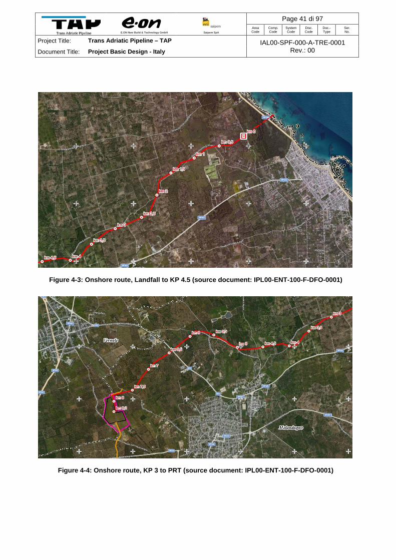
three times more, at KP 1.1, KP 2 and KP 4. The route continues its course mainly through olive
plantations seeking the side of the road where possible, crossing another provincial road, the
”Strada provinciale Lecce Melendugno” (SP2) at KP 6.5. At a total onshore route length of
approx. 8.2 kilometres, the pipeline reaches the PRT area west of the township of Melendugno.
This terminal station will be situated closed to the border between Melendugno and Vernole,
approximately 1.5 kilometres south of the provincial road connecting these towns.
The examined section does not present particular problems and the morphology of the territory
consists predominantly of rolling plains, slightly undulating locally.
E.ON New Build & Technology GmbH
Saipem SpA
Page 41 di 97 Area Code
Comp. Code
System Code
Disc. Code
Doc.- Type
Ser. No.
Project Title: Trans Adriatic Pipeline – TAP IAL00-SPF-000-A-TRE-0001 Rev.: 00 Document Title: Project Basic Design - Italy
Figure 4-3: Onshore route, Landfall to KP 4.5 (source document: IPL00-ENT-100-F-DFO-0001)
Figure 4-4: Onshore route, KP 3 to PRT (source document: IPL00-ENT-100-F-DFO-0001)

E.ON New Build & Technology GmbH
Saipem SpA
Page 42 di 97 Area Code
Comp. Code
System Code
Disc. Code
Doc.- Type
Ser. No.
Project Title: Trans Adriatic Pipeline – TAP IAL00-SPF-000-A-TRE-0001 Rev.: 00 Document Title: Project Basic Design - Italy
5 CONSTRUCTION METHOD AND INSTALLATION
5.1 Offshore, Nearshore and Landfall Sections
5.1.1 Pipelaying
The offshore pipeline will be installed using a laybarge. Pipe sections are welded together on the
barge and the lengthening pipe string is paid out to the seabed as the barge moves along the
route. Special measures will need to be employed (i.e. concrete mattressing or rock dumping) at
crossings such as cables, within the surveyed corridor. The pipe-lay operation will be performed
on a 24-hour basis to ensure minimal navigational impact on other users and to maximise
efficient use of suitable weather conditions and vessel and equipment time. In addition to the
installation vessel, additional support, supply and guard vessels will be involved with the
operation.
Normal pipe laying activity will consist of the following main operations:
• Pipe Damage inspection
• Firing ramp operation
• Welding
• Lay barge movement
• Pipeline installation
Pipe Damage Inspection
Prior to transfer the single pipe joint from the storage area, a visual inspection will be performed
to locate any damage to coating and/or dent, and to assure internal cleanness. The internal part
of the lines will be cleaned and any damage to the pipe coating will be repaired.
Firing Ramp Operation
The laying operations on the firing ramp will be carried out in the following operational sequence:
• Prior to the start of pipe laying, the roller heights and stinger configuration will be established in accordance with laying parameters determined as per stress analysis.
• At the station no. 1, the pipe joints alignment will be completed using pneumatic line-up clamp.

E.ON New Build & Technology GmbH
Saipem SpA
Page 43 di 97 Area Code
Comp. Code
System Code
Disc. Code
Doc.- Type
Ser. No.
Project Title: Trans Adriatic Pipeline – TAP IAL00-SPF-000-A-TRE-0001 Rev.: 00 Document Title: Project Basic Design - Italy
• The root pass will be completed at the 1st station, following which the Lay Barge will move to a distance equivalent to one pipe joint length. Subsequent hot and fill passes will be carried at other welding stations.
• On completion of NDT examination, the field joint coating will be performed.
Figure 5-1 Example of Firing Ramp Operation
Welding
Welding at the firing ramp of the Lay Barge will be carried out using mechanized welding system.
The system is completely mechanised and needs the operator intervention only to control the
welding parameters. Once the parameters are carefully fixed, the quality of the weld is highly
consistent.
The welding procedure and welder qualification will be carried out before mobilisation for the
offshore installation work. The qualifications will be performed at selected onshore base.
Qualified welders, NDT Operators and Supervisors will be mobilised to perform the work.
Lay barge Movement
After the above mentioned activities are completed on all work stations, the Lay Barge will be
moved on its anchors for a distance equivalent to one single joint length, so that new joint can be
conveyed to the firing ramp. The movement of the Lay Barge will be achieved by reeving back
the bow mooring cables and simultaneously paying out the stern mooring cables (see Figure
5-2).
After the Lay barge has moved for a distance of one joint length, the operation will be repeated at
each work station. The anchors movement will be periodically performed with assistance at AHT's
and with deployed positioning systems.

E.ON New Build & Technology GmbH
Saipem SpA
Page 44 di 97 Area Code
Comp. Code
System Code
Disc. Code
Doc.- Type
Ser. No.
Project Title: Trans Adriatic Pipeline – TAP IAL00-SPF-000-A-TRE-0001 Rev.: 00 Document Title: Project Basic Design - Italy
The Lay Barge position and heading will be continuously monitored by means of the surface
positioning systems. After each joint move, a fix will take the giving joint number, the heading and
co-ordinates referred to a station on the firing line. The Lay Barge will be kept on its correct
headings so that the pipeline is laid within the required tolerance with respect to the centre line of
the theoretical route.
Figure 5-2 Mooring system for Lay barge movement
Pipeline installation
The pipeline installation will be performed by means of a pull-in from offshore lay-barge anchored
at water depth around 40 m. The anchor pattern does not interfere with Posidonia area. A land
based winch, having a pulling capacity of 400 tons, approximately, shall be placed in the working
area, in the proximity of the tunnel shaft.

E.ON New Build & Technology GmbH
Saipem SpA
Page 45 di 97 Area Code
Comp. Code
System Code
Disc. Code
Doc.- Type
Ser. No.
Project Title: Trans Adriatic Pipeline – TAP IAL00-SPF-000-A-TRE-0001 Rev.: 00 Document Title: Project Basic Design - Italy
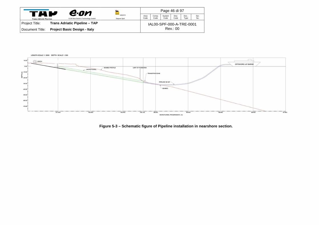
Offshore lay-barge starts the pipeline current laying as soon as the pipe pulling head reaches the
launch shaft. The onshore pulling facilities will be demobilized after the laying of a sufficiently long
pipe string. The current laying has to be done till the target area located in proximity of Albania.
E.ON New Build & Technology GmbH
Saipem SpA
Page 46 di 97 Area Code
Comp. Code
System Code
Disc. Code
Doc.- Type
Ser. No.
Project Title: Trans Adriatic Pipeline – TAP IAL00-SPF-000-A-TRE-0001 Rev.: 00 Document Title: Project Basic Design - Italy
Figure 5-3 – Schematic figure of Pipeline installation in nearshore section.

E.ON New Build & Technology GmbH
Saipem SpA
Page 47 di 97 Area Code
Comp. Code
System Code
Disc. Code
Doc.- Type
Ser. No.
Project Title: Trans Adriatic Pipeline – TAP IAL00-SPF-000-A-TRE-0001 Rev.: 00 Document Title: Project Basic Design - Italy
5.1.2 Pre-dredging works
A trench shall be excavated, with a Back-hoe Dredger (BHD), before the pipeline installation,
between KPof 103.490 and KP 103.381, at a distance of 868m and 977m from the shore line,
respectively. The water depth ranges between 18 and 27m.
The scopes of the trench are:
• To prepare an almost strait surface for the pull-in and the laying of the pipeline,
• To recover the MTBM in the proximity of the tunnel exit seawards (KPof 103.500).
The BHD is an excavator which is fixed to a pontoon (see Figure 5-4). The excavator is based on
a lowered turntable at the front of the pontoon. Dredging is achieved in the same way a land
based excavator. The BHD has a stick and boom with a bucket mounted on it.
The main components of the BHD consist of:
• The hull, contains the engines and the accommodation for the crew
• The excavator, used for the dredging operations
Figure 5-4 Example of a BHD
Different types of buckets can be used for different soils. For harder material the smaller bucket
(7m3) will be used which can penetrate in the material with his teeth’s.
Dredging with a backhoe dredge is not a continuous process, but consists of a cycle of
Operations.

E.ON New Build & Technology GmbH
Saipem SpA
Page 48 di 97 Area Code
Comp. Code
System Code
Disc. Code
Doc.- Type
Ser. No.
Project Title: Trans Adriatic Pipeline – TAP IAL00-SPF-000-A-TRE-0001 Rev.: 00 Document Title: Project Basic Design - Italy
The bucket is dredging into the subsoil by a backward movement of boom and upward movement
of stick and bucket. When the bucket is filled, a further upward movement of the boom and stick
is ensuring sufficient height above the bottom to start swinging.
The material will be discharged sideway of the trench and will be used for the backfilling after the
layng of the pipeline.
5.1.3 Post-trenching works A post-trenching machine may be utilised to lower the pipe into the soil to an assigned
embedment, and provide a suitable cover.
The trenching systems usually consist in ROV equipment to perform trenching tasks.
These machines utilize predominantly jetting based excavation systems, possibly in combination
with trenching wheels.
5.1.4 Gravel dumping The offshore Rock dumping is based on the Fall Pipe Method illustrated in the sketch of Figure
5-5. The method is used for placing gravel heaps in deep water, with a good precision, with the
following purposes:
• to provide pre-lay or post lay support to the pipeline
• to cover it for protection purposes or preventing in-service buckling
• to build crossings of existing pipelines and cables.
The vessels which perform gravel dumping are usually multi-purpose, in particular equipped with
a flexible fallpipe with an ROV at the lower end for better positioning. Gravel is dumped through
the fallpipe at a controlled rate. The vessel moves along the route under dynamic control. The
ROV is controlled from the ship, and ensure an accurate positioning.

E.ON New Build & Technology GmbH
Saipem SpA
Page 49 di 97 Area Code
Comp. Code
System Code
Disc. Code
Doc.- Type
Ser. No.
Project Title: Trans Adriatic Pipeline – TAP IAL00-SPF-000-A-TRE-0001 Rev.: 00 Document Title: Project Basic Design - Italy
Figure 5-5 Fall Pipe ROV 5.1.5 Marine Spreads
The following main marine vessels and their auxiliary spreads will be employed for the execution
of the above mentioned works:
• Backhoe dredger
• Motopontoon
• Pipelay barge
• Anchor Handling Tug
• Pipe carrier Barge
• Supply vessel
• Survey vessel
• Crew boat
• Dive Support Vessel
• Fall pipe vessel
• Supply vessel for post-trenching
FALL PIPE ROV

E.ON New Build & Technology GmbH
Saipem SpA
Page 50 di 97 Area Code
Comp. Code
System Code
Disc. Code
Doc.- Type
Ser. No.
Project Title: Trans Adriatic Pipeline – TAP IAL00-SPF-000-A-TRE-0001 Rev.: 00 Document Title: Project Basic Design - Italy
5.1.6 Microtunnel The landfall realization of the gas pipeline on the Italian coast is based on micro-tunnel
technology, see Figure 5-8 for a sketch of the near shore and landfall solution.
The tunnel route on horizontal plane has been defined considering as follows:
• Straight path on the horizontal plane, in order to allow an easier pull-in and prevent any
jeopardizing contact between pipeline and lateral tunnel walls during pull-in;
• The onshore entry point has been defined in order to cross the Provincial Road SP n.
366, outside the area of hydrogeological constraint (Figure 5-6).
• The location of the coast line crossing has been selected to maintain the largest distances
from buildings, particularly from those which can accommodate over 100 people.
• The offshore exit point of the micro-tunnel has been defined in order to avoid
environmental sensitive areas. In fact, the offshore exit point of the tunnel was set at least
50m away from the border of this vegetation, on the basis of the results of the sediment
dispersion study.
Figure 5-6: Extract of the Hydrogeological Risk Plan

E.ON New Build & Technology GmbH
Saipem SpA
Page 51 di 97 Area Code
Comp. Code
System Code
Disc. Code
Doc.- Type
Ser. No.
Project Title: Trans Adriatic Pipeline – TAP IAL00-SPF-000-A-TRE-0001 Rev.: 00 Document Title: Project Basic Design - Italy
Figure 5-7: Onshore entry point of the microtunnel
The tunnel route on vertical plane has been defined considering as follows:
• Straight or moderately curved path on the vertical plane. The self-weight of the pipeline
allows it to follow small curvatures of the tunnel. In this case, tunnel-pipeline contact
forces are only related to pipeline self-weight and friction. In case of excessive curvatures,
high local contact forces can be activated, due to pulling loads and pipe stiffness.
• In order to obtain a safe cover height, the depth of the tunnel exit point has been set to
3.5m, with an inclination close to the sea bottom slope and set to minimize gravel
dumping in front of the tunnel exit.
• The vertical shape of the tunnel to be also defined on the basis of specific analysis of pull-
in procedure and of pipeline configuration.

E.ON New Build & Technology GmbH
Saipem SpA
Page 52 di 97 Area Code
Comp. Code
System Code
Disc. Code
Doc.- Type
Ser. No.
Project Title: Trans Adriatic Pipeline – TAP IAL00-SPF-000-A-TRE-0001 Rev.: 00 Document Title: Project Basic Design - Italy
Figure 5-8: Sketch of near shore solution.
The resulting length of the tunnel is 1485m. The selected diameter is equal to 2.4m inside, 3.0m
outside.
A brief description of activities to be performed for micro tunnel realization is reported in the
following:
The Micro-tunnel (MT) is executed with the pipe jacking technique which basically consists of
pushing reinforced concrete pipes, which have been previously transported to the site, into the
soil. The Tunnel Boring Machine (TBM) is lowered into a previously excavated and stable jacking
shaft with the required dimensions. The pipes are pushed by means of a set of hydraulic
cylinders and a TBM that at the same time of pushing is excavating the front. The soil is removed
from the excavation front and transported to the shaft by means of a dedicated circuit.

E.ON New Build & Technology GmbH
Saipem SpA
Page 53 di 97 Area Code
Comp. Code
System Code
Disc. Code
Doc.- Type
Ser. No.
Project Title: Trans Adriatic Pipeline – TAP IAL00-SPF-000-A-TRE-0001 Rev.: 00 Document Title: Project Basic Design - Italy
Figure 5-9: Micro-tunnel overview.
The sea bottom area in front of the micro-tunnel exit, where the pipeline has to be laid on and
pulled to enter into the tunnel, is prepared with pre-trench and gravel dumping, to avoid any
pipeline stuck and to prevent damages to the coating.
After completion of the MT and the recovery of the machine from the seabed, the pipeline is
pulled in with the help of a winch and sheave system.
Finally the pre-trench is also backfilled. Figure 5-9 shows and overview of the basic layout and
principles of the pipe jacking technique.
The micro-tunnelling activities consist of the following phases:
• Site preparation
• Jacking shaft construction (thrusting wall)

E.ON New Build & Technology GmbH
Saipem SpA
Page 54 di 97 Area Code
Comp. Code
System Code
Disc. Code
Doc.- Type
Ser. No.
Project Title: Trans Adriatic Pipeline – TAP IAL00-SPF-000-A-TRE-0001 Rev.: 00 Document Title: Project Basic Design - Italy
• Pre-dredging and exit point preparation
• Drilling the Micro-tunnel along the designed axis
• Works completion inside the micro-tunnel (recovery of slurry and cables and installation of
FOC conduits)
• Recovery of TBM inside the pre-dredged exit
• Winch anchoring installation, wire lay and shore pulling
• Pipeline pulling
• FOC pulling
• Site restoration
5.1.7 Shaft
The jacking shaft, is needed in order to ensure the correct alignment of the Micro-tunnel (Figure
5-9), and is prepared at the starting point of the micro-tunnel.
TBM shall be designed and tailored in consideration of the expected soil/rock conditions; a
hydraulic jacking system pushes the concrete lining pipe continuously (Figure 5-10), a closed
loop slurry system removes the spoil from the rotating drilling shield on the front. Intermediate
jacking system are designed and installed, when length of drilled section requires, in order to
sectionalize the total pushing force.
A lubrication system using special muds, pumped through hoses on the external lining surface, is
foreseen to facilitate the concrete lining insertion and progress in the sub soil.
The bottom of the shaft has to be realized approximately at the mean sea level. Resulting shaft
depth is about 10m.
Figure 5-10 shows a typical launch shaft.
Figure 5-11 shows joints details used to ensure the tightness of the tunnel.

E.ON New Build & Technology GmbH
Saipem SpA
Page 55 di 97 Area Code
Comp. Code
System Code
Disc. Code
Doc.- Type
Ser. No.
Project Title: Trans Adriatic Pipeline – TAP IAL00-SPF-000-A-TRE-0001 Rev.: 00 Document Title: Project Basic Design - Italy
Figure 5-10: Typical launch shaft.
Figure 5-11: Pipe joint detail.
steel collar
soft fibre board packer
rubber seal

E.ON New Build & Technology GmbH
Saipem SpA
Page 56 di 97 Area Code
Comp. Code
System Code
Disc. Code
Doc.- Type
Ser. No.
Project Title: Trans Adriatic Pipeline – TAP IAL00-SPF-000-A-TRE-0001 Rev.: 00 Document Title: Project Basic Design - Italy
5.1.8 Exit Point - Pre-dredging and TBM recovery
After completion of micro-tunnel construction, TBM has to be recovered. Before recover, TBM is
not stiffly kept in place, has a significant buoyancy and could be moved by sea waves-currents.
Therefore, the exit location is designed to provide the TBM rests under about 3m of sand, but
recover has to be performed as soon as possible.
The recovery of the drilling head at the exit point requires dredging works. For this purpose, the
final jacking pipes (the first of which are following the drilling head at the beginning of the job) is
dimensioned to ensure the stability of the part of the tunnel without soil cover in the dredged
trench.
Work on the pre-dredged trench will be carried out by a backhoe dredger, Figure 5-12, in order to
prepare exit point of the tunnel, the laying of the pipeline, and to recover the TBM in the proximity
of the tunnel exit, seawards.
Excavated material is temporary displaced on a side of the pipeline route, to be reused in the
following sea bottom works.
Sea bottom is pre-trenched in front of the Micro-tunnel and then embankment realized to gently
get a smooth pipeline configuration, see Figure 5-13, and facilitate the pipeline laying and its
insertion into the tunnel. These activities are performed just after and with the same vessel used
to prepare the tunnel exit point for TBM recovery. The water depth is approximately 20m-25m.
Pipeline and FOC at the exit point and for a certain length, after their installation, are covered by
the excavated material.
Figure 5-12: Example of backhoe dredger.

E.ON New Build & Technology GmbH
Saipem SpA
Page 57 di 97 Area Code
Comp. Code
System Code
Disc. Code
Doc.- Type
Ser. No.
Project Title: Trans Adriatic Pipeline – TAP IAL00-SPF-000-A-TRE-0001 Rev.: 00 Document Title: Project Basic Design - Italy
Figure 5-13: Schematic of pre-lay preparation work in front of micro-tunnel exit point.
A barge with a crane will be positioned where the Tunnel Boring Machine will be lifted. The
connection of the TBM with the crane will be made by divers. Once recovered, the TBM will be
transported to the support harbour. The following Figure 5-14 shows the sequence of performed
works.
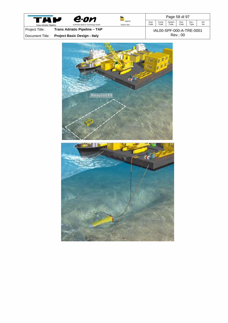
E.ON New Build & Technology GmbH
Saipem SpA
Page 58 di 97 Area Code
Comp. Code
System Code
Disc. Code
Doc.- Type
Ser. No.
Project Title: Trans Adriatic Pipeline – TAP IAL00-SPF-000-A-TRE-0001 Rev.: 00 Document Title: Project Basic Design - Italy

E.ON New Build & Technology GmbH
Saipem SpA
Page 59 di 97 Area Code
Comp. Code
System Code
Disc. Code
Doc.- Type
Ser. No.
Project Title: Trans Adriatic Pipeline – TAP IAL00-SPF-000-A-TRE-0001 Rev.: 00 Document Title: Project Basic Design - Italy

E.ON New Build & Technology GmbH
Saipem SpA
Page 60 di 97 Area Code
Comp. Code
System Code
Disc. Code
Doc.- Type
Ser. No.
Project Title: Trans Adriatic Pipeline – TAP IAL00-SPF-000-A-TRE-0001 Rev.: 00 Document Title: Project Basic Design - Italy
Figure 5-14: Sequence of drawings and photos of the works performed for recovery an TBM and
transport it to the near harbour.
Following the removal of the tunnelling equipment from the micro-tunnel, messenger wires are
pre-laid inside the tunnel and a special bell-mouth entry section is installed at the sea end, to
safely guide the pipeline from the dredged trench into the micro-tunnel.

E.ON New Build & Technology GmbH
Saipem SpA
Page 61 di 97 Area Code
Comp. Code
System Code
Disc. Code
Doc.- Type
Ser. No.
Project Title: Trans Adriatic Pipeline – TAP IAL00-SPF-000-A-TRE-0001 Rev.: 00 Document Title: Project Basic Design - Italy
There is a potential risk that, as the pipeline is pulled into the micro-tunnel, the weight and
dynamic loads may displace the tunnel sections at the entrance leading to a blockage or damage
to the pipeline.
This issue is addressed by welding together the leading sections of tunnel segments (this is a
standard practice), and by providing a bell-mouth structure at the micro-tunnel exit, for guiding
the pipeline into the tunnel. The use of such guiding system allows a smooth transition for the
pipeline pull from the seabed into the tunnel.
The bell-mouth structure will provide the following:
• A slope from the dredged trench into the micro-tunnel invert to avoid the pulling head
snagging on the face of the tunnel in both the vertical or horizontal plane.
• Sufficient foundation area to avoid the load from the pulling head and pipeline transferring
suddenly to the first segment of the tunnel.
The bell-mouth is a steel structure that is positioned using the same crane barge that will remove
the TBM. The end tunnel segment to be designed to accept the bell-mouth.
Pull-in and installation Pipeline pull-in inside the micro-tunnel is usually the most challenging activity in landfall
realization. Nevertheless, a wide experience is actually available in the world and no specific
critical issue is anticipated.
The pulling force required for Pipeline pull-in is preliminary calculated summing friction forces
(due to the submerged weight of the pipeline in contact with the sea bottom-tunnel floor) and the
pulling force required to the lay barge to prevent overstressing on the pipeline on the laying span.
A scheme of the pipeline insertion inside the tunnel is shown in Figure 5-15.
The submerged weight of the pipe with 34mm wall thickness is about 503 N/m.
Applying a friction factor of 0.7, the resulting winch force is about 320 tons.
As preliminary value, considering a relevant margin for contingency, 380 tons pulling force are
considered.
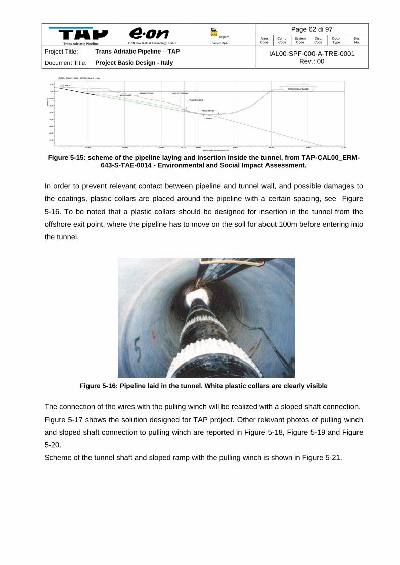
E.ON New Build & Technology GmbH
Saipem SpA
Page 62 di 97 Area Code
Comp. Code
System Code
Disc. Code
Doc.- Type
Ser. No.
Project Title: Trans Adriatic Pipeline – TAP IAL00-SPF-000-A-TRE-0001 Rev.: 00 Document Title: Project Basic Design - Italy
Figure 5-15: scheme of the pipeline laying and insertion inside the tunnel, from TAP-CAL00_ERM-
643-S-TAE-0014 - Environmental and Social Impact Assessment.
In order to prevent relevant contact between pipeline and tunnel wall, and possible damages to
the coatings, plastic collars are placed around the pipeline with a certain spacing, see Figure
5-16. To be noted that a plastic collars should be designed for insertion in the tunnel from the
offshore exit point, where the pipeline has to move on the soil for about 100m before entering into
the tunnel.
Figure 5-16: Pipeline laid in the tunnel. White plastic collars are clearly visible
The connection of the wires with the pulling winch will be realized with a sloped shaft connection.
Figure 5-17 shows the solution designed for TAP project. Other relevant photos of pulling winch
and sloped shaft connection to pulling winch are reported in Figure 5-18, Figure 5-19 and Figure
5-20.
Scheme of the tunnel shaft and sloped ramp with the pulling winch is shown in Figure 5-21.

E.ON New Build & Technology GmbH
Saipem SpA
Page 63 di 97 Area Code
Comp. Code
System Code
Disc. Code
Doc.- Type
Ser. No.
Project Title: Trans Adriatic Pipeline – TAP IAL00-SPF-000-A-TRE-0001 Rev.: 00 Document Title: Project Basic Design - Italy
Figure 5-17: Sloped shaft connection with pulling winch
Figure 5-18: Photo of a pulling winch
Figure 5-19: Photo with a relevant example of a sloped shaft connection to the pulling winch
length and size to be defined

E.ON New Build & Technology GmbH
Saipem SpA
Page 64 di 97 Area Code
Comp. Code
System Code
Disc. Code
Doc.- Type
Ser. No.
Project Title: Trans Adriatic Pipeline – TAP IAL00-SPF-000-A-TRE-0001 Rev.: 00 Document Title: Project Basic Design - Italy
Figure 5-20: Photo with a relevant sloped shaft connection realized at Langeled entry point into the micro-tunnel
Figure 5-21: Scheme of Micro-tunnel shaft and sloped ramp with pulling winch
The rough procedure for pipeline installation inside the micro-tunnel (see Figure 31) is:
• Messenger wires pre-laid inside the tunnel are recover on board of the pipelay vessel.
• Main pull wires are inserted and pulled onshore by the winch.
• Laybarge starts to weld together linepipes, the winch placed onshore pulls them.
• Pipe laying continues until the pipe string is installed in the micro-tunnel and reaches the
micro-tunnel head
• The pipeline vessel continues laying the pipeline offshore

E.ON New Build & Technology GmbH
Saipem SpA
Page 65 di 97 Area Code
Comp. Code
System Code
Disc. Code
Doc.- Type
Ser. No.
Project Title: Trans Adriatic Pipeline – TAP IAL00-SPF-000-A-TRE-0001 Rev.: 00 Document Title: Project Basic Design - Italy
Figure 5-22: Main points of the procedure for pipeline installation inside the micro-tunnel
Finally, at the end of pipeline installation, micro-tunnel will be left flooded with sea water.
After the tunnel exit point closure (without sealing), also the entry point will be closed. Venting
pipes will be installed at the entry point, allowing any leaking gas (inside the tunnel) to be
discharged in the air. Notably, a gas methane detector sensor will also be installed for leak
detection.
Yard and facilities Facilities and features required during micro-tunnel construction include the following:
• Work sites;

E.ON New Build & Technology GmbH
Saipem SpA
Page 66 di 97 Area Code
Comp. Code
System Code
Disc. Code
Doc.- Type
Ser. No.
Project Title: Trans Adriatic Pipeline – TAP IAL00-SPF-000-A-TRE-0001 Rev.: 00 Document Title: Project Basic Design - Italy
• Construction site (with pipe stockyard);
• Pipeline Protection;
• Leak Reduction Instruments;
• Access Roads.
The major plant items needed are bulldozers, heavy excavators, spoil removal trucks, large
heavy-lift cranes, standby generators, micro-tunnel boring machine, excavators, rock breakers,
etc.
The main equipment used for construction is described in the following, particularly the yacking
pit and the pulling spread arrangement.
A temporary worksite is needed for the construction of the offshore micro-tunnel and occupy an
area of about 26,000m2 (see Figure 5-24). The launch shaft is to be located here. The temporary
worksite will also be used for placing the pre-commissioning spread of the offshore pipeline.
A total of approximately 8000 m3 of soil will be temporary set aside in order to prepare the
working area. This material will be redistributed on the area after the works completion.
Figure 5-23: Temporary Worksite for Microtunnel and Pre-commissioning spread

E.ON New Build & Technology GmbH
Saipem SpA
Page 67 di 97 Area Code
Comp. Code
System Code
Disc. Code
Doc.- Type
Ser. No.
Project Title: Trans Adriatic Pipeline – TAP IAL00-SPF-000-A-TRE-0001 Rev.: 00 Document Title: Project Basic Design - Italy
Figure 5-24: Schematic of equipment in the Construction yard and Stocking area.
5.1.9 Jacking pit
Secant piles are a common and fast technique to construct the jacking shaft. Since piles are to
be inserted in the solid rock, exaction and concrete floor will be executed in dry conditions.
The axis of the micro-tunnel to be positioned in the most favourable position in terms of
geological conditions. The pit floor to be sloped with the same angle of the micro-tunnel entry.
An anchoring arrangement is constructed behind the winch location.
5.1.10 Pulling spread arrangement
A linear winch and reel to be set up with a holdback anchor system. The pull capacity of the
winch to be suitable for total pulling and contingency, and fitted with a 3-inch diameter steel wire
rope. The winch fixation to be designed to transfer the maximum pulling loads from the winch to
the ground and to be constructed, in any case, such as to withstand the maximum pulling force.
For the installation of the pulling equipment, a hydraulic mobile crane is anticipated to be
frequently on site.

E.ON New Build & Technology GmbH
Saipem SpA
Page 68 di 97 Area Code
Comp. Code
System Code
Disc. Code
Doc.- Type
Ser. No.
Project Title: Trans Adriatic Pipeline – TAP IAL00-SPF-000-A-TRE-0001 Rev.: 00 Document Title: Project Basic Design - Italy
Figure 5-25: Typical Pulling spread arrangement.
The Pull-in of the 36” gas pipeline inside the tunnel is performed using a winch, as in the scheme
reported in Figure 5-25.
Slurry treatment The excavated soil will be mixed with slurry (water) in the TBM extraction chamber. Large slurry
pumps in the tunnel section behind the TBM will transport the soil mud mixture through slurry
pipes to the departure site. The mud will be de-sanded in a recycling plant. The cleaned slurry
will be reversed to the front.
The efficiency of the soil separation plant will be of major importance.
Indeed, once the water in the tunnel circuit will get saturated with fine sand or clay particles, the
slurry will not be able to take any soil from the machine front anymore. The front pressure will
increase and the jacking performance will drop significantly. High front pressures could produce
cracks in the overburden which could lead into bentonite escape.
Once the slurry will have been saturated with silt/clay, it will be replaced by water. The saturated
slurry will be removed from the slurry containers and disposed into the storage pool for slurry.
While the tunnelling operations continue with water, the dewatering installation treats the
saturated slurry.
In a first phase, some polymers will be added to the slurry in order to make small particles bond
together.
The flocculated slurry will then enter into a band filter press.
The polymer injection will be fully controlled. Dosage, polymer adaptation and monitoring will be
followed during the complete tunnelling operations.
The band filter press basically consists of an upper and a lower permeable belt. Both belts turn at
the same speed. The lower belt will transport the slurry from one side of the machine to the other
side. During the transport cycle, the space between the two belts will progressively be reduced to
squeeze out the water. The dewatered silt/clay will fall on a conveyer belt and will come out of the
machine. The soil separated can then be loaded on trucks.

E.ON New Build & Technology GmbH
Saipem SpA
Page 69 di 97 Area Code
Comp. Code
System Code
Disc. Code
Doc.- Type
Ser. No.
Project Title: Trans Adriatic Pipeline – TAP IAL00-SPF-000-A-TRE-0001 Rev.: 00 Document Title: Project Basic Design - Italy
The estimated water that will be utilized for the offshore microtunnel can be estimated in 10,000
cubic meter.
Cleaning and Hydro-testing
The Hydrostatic testing operation will commence upon successful completion and acceptance of
flooding, cleaning and gauging operation. Hydrostatic testing will be performed as per DNV OS-
F101.
Seawater injected during hydro-test shall also be provided by the water-winning system and
therefore shall have been subjected to a filtration process with the specification at 50µ particle
size and UV sterilised accordingly.
Pressurisation water shall be supplied via the same water-winning system used for flooding,
cleaning and gauging and post hydrotest water shall be discharged using the dumpline facility
installed in Albania.
Pressurisation of the pipeline shall be conducted at a rate of 0.5barg/min up to 95% of test
pressure. At this stage and in accordance with DNV-OS-101 (2012) final pressurisation to the
strength test pressure shall be performed at a lower pressurisation rate.
On reaching test pressure, stabilisation of the test medium shall be required prior to starting the
24hr hold period. It is estimated that stabilisation may take up to two days with particular
reference to the rate of heat transfer across the pipe wall and the difference between filling water
and deepwater sea temperatures. Therefore the overall pipeline hydrotest duration including
depressurisation is calculated to take approximately five days.
The sea water volume that will be discharged during cleaning and hydotest of the whole pipeline
can be estimated in 130,000 cubic meter. De-Watering The pipeline dewatering pig train will be launched from the Italian landfall site and shall
incorporate slugs of fresh water to desalinate the pipeline. The pig train design shall also include
dry compressed air slugs to remove residual water. The fresh water slugs will be stored in
multiple storage bladders and these will be positioned on a prepared stone free area with a slight
elevation.
The fresh water pumping equipment shall be flushed prior to use with the first batch of fresh
water being injected behind the first pig in the dewatering pig train.
The sea water volume that will be discharged during de-watering of the whole pipeline can be
estimated in 65,000 cubic meter.
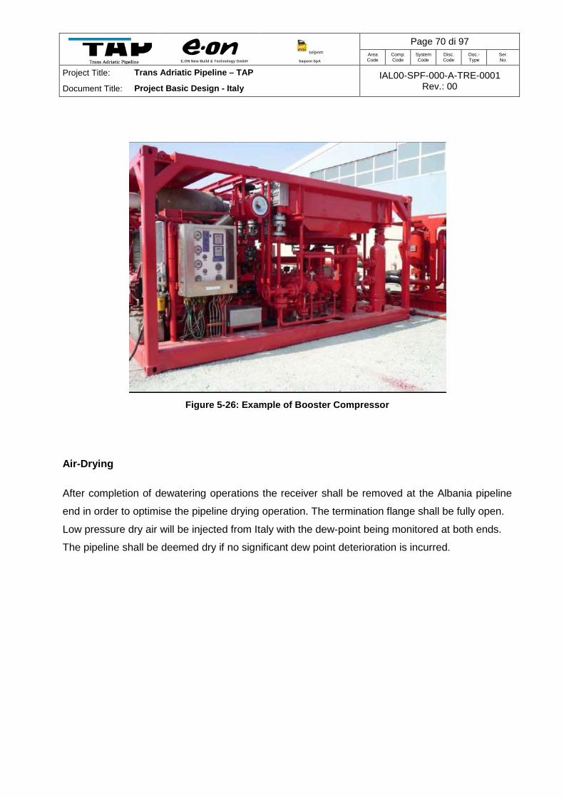
E.ON New Build & Technology GmbH
Saipem SpA
Page 70 di 97 Area Code
Comp. Code
System Code
Disc. Code
Doc.- Type
Ser. No.
Project Title: Trans Adriatic Pipeline – TAP IAL00-SPF-000-A-TRE-0001 Rev.: 00 Document Title: Project Basic Design - Italy
Figure 5-26: Example of Booster Compressor
Air-Drying After completion of dewatering operations the receiver shall be removed at the Albania pipeline
end in order to optimise the pipeline drying operation. The termination flange shall be fully open.
Low pressure dry air will be injected from Italy with the dew-point being monitored at both ends.
The pipeline shall be deemed dry if no significant dew point deterioration is incurred.

E.ON New Build & Technology GmbH
Saipem SpA
Page 71 di 97 Area Code
Comp. Code
System Code
Disc. Code
Doc.- Type
Ser. No.
Project Title: Trans Adriatic Pipeline – TAP IAL00-SPF-000-A-TRE-0001 Rev.: 00 Document Title: Project Basic Design - Italy
5.2 Onshore Section
The operating phases involved in the construction of the pipeline are described briefly in the
subsections below.
A single storage and work site is foreseen mainly as stock and bending yard for the line pipes.
The location is at the end of the route at KP 8.2 in a large arable land patch area where also the
receiving terminal will be built up. It will be used as the only stockyard for the onshore pipeline in
Italy and will be easily accessible through the existing road network (SP366, SP245 and
connected asphalt roads).
No accommodation for workers is considered at the aforementioned site. The whole extent of the
land parcels affected presumably amounts to
• 33 hectare as land-easement for pipeline safety zone
o incl. 21 hectare for temporary construction,
• 12 hectare as land acquisition for the pemanent receiving terminal
o incl. 5 hectare for fabrication and material storage.
The area of 21 hectare assigned for pipeline construction includes only partly (up to the extent of
the ROW) the temporary worksite which is foreseen for the construction of the landfall
microtunnel which is part of the offshore pipeline.
The construction period for the pipeline is estimated with 6 months and for the terminal 18
months. Site preparation (clearing of topsoil and levelling works) should be done in advance to
this period. The completion of the landscaping and road construction is considered to follow
afterwards.
5.2.1 Pipeline installation
The trench digging operations and pipeline assembly require the opening of a working strip.
The overall width of this working strip will be limited to 26 m which is good engineering practice in
cultivated areas, one side approx. 11 m wide for the disposal of trench excavated material while
the other one side, a strip approx. 15 m wide to allow the pipeline assembling and for the
vehicles/machinery transit required for the pipeline construction.
Before opening the working strip, the top soil layer will be set aside at the edge of the strip, for re-
use during the restoration phase.

E.ON New Build & Technology GmbH
Saipem SpA
Page 72 di 97 Area Code
Comp. Code
System Code
Disc. Code
Doc.- Type
Ser. No.
Project Title: Trans Adriatic Pipeline – TAP IAL00-SPF-000-A-TRE-0001 Rev.: 00 Document Title: Project Basic Design - Italy
Figure 5-27: Reduced working strip for special cultivated areas
(source document: CPL00-ENT-100-F-DFT-0011)
At stretches which are limited to several hundred metres or connected to access roads, the
working strip can be reduced to 22 metres due to technical reasons.

E.ON New Build & Technology GmbH
Saipem SpA
Page 73 di 97 Area Code
Comp. Code
System Code
Disc. Code
Doc.- Type
Ser. No.
Project Title: Trans Adriatic Pipeline – TAP IAL00-SPF-000-A-TRE-0001 Rev.: 00 Document Title: Project Basic Design - Italy
Figure 5-28: Reduced working strip for special cultivated areas
(source document: CPL00-ENT-100-F-DFT-0011)
The trench will be cut by excavators and or adequate earth moving machinery suitable for the
morphological and lithological characteristics of the ground to be crossed (excavators in loose
ground, hydraulic hammers in rock). A pre-defined sand bedding will be applied to the trench
bottom, when the required conditions are not reached (rocky area).
The pipes will be bent where required acc. to the trench dimensions and joined together using a
motor-driven welding machine by a continuous wire arc welding process. The pipe joining will be
made by connecting and welding several pipes so that, a pipe string is formed aside the trench.
After having performed the anti-corrosion coating check by means of holiday detector to ensure
that the coating is perfectly intact, the pipe string section will be lifted and laid down into the
trench by sidebooms (especially equipped bulldozers).
The laid pipeline will be buried with a pre-defined padding first, composed alike the bedding of
selected material, and then will be backfilled with trench excavation material. Generally, it is
strived through insitu preparation process that the quality of the bedding material is achieved so

E.ON New Build & Technology GmbH
Saipem SpA
Page 74 di 97 Area Code
Comp. Code
System Code
Disc. Code
Doc.- Type
Ser. No.
Project Title: Trans Adriatic Pipeline – TAP IAL00-SPF-000-A-TRE-0001 Rev.: 00 Document Title: Project Basic Design - Italy
that all of the excavated material is re-used for the backfilling. Finally the top soil will be spread
and the whole working strip will be re-instated.
5.2.2 Crossings
The crossings are implemented as small stand alone “worksites” that come into operation as the
line progresses. The crossing installation methods are different and can generally be carried out
by trenchless (tunneling or boring) or open-cut techniques, with or without casing pipe. The
choice of the installation system depends on a number of factors, including: laying depth,
presence of water or rock, intensity of traffic, authority requirements, etc.
There is three envisaged trenchless crossings, two of which are actually part of the approximately
1.5 km landfall tunnel as described under the offshore section.
5.2.3 Hydro-test
Following the pipeline construction and backfill, a hydro-test shall be performed, by filling and
pressurising the line with water at a pressure of presumably 1.3 times the maximum pipeline
operating pressure for a period of 48 hours (according to DM 17/04/2008). Hydro-test is usually
carried out on separated pipeline sections dependant on the work progress at road crossings or
special sections. The approximate volume of water required for the hydro-test of the onshore
pipeline is 4,900 cubic metres.

E.ON New Build & Technology GmbH
Saipem SpA
Page 75 di 97 Area Code
Comp. Code
System Code
Disc. Code
Doc.- Type
Ser. No.
Project Title: Trans Adriatic Pipeline – TAP IAL00-SPF-000-A-TRE-0001 Rev.: 00 Document Title: Project Basic Design - Italy
6 CONSTRUCTION TIMING
The following Table 6-1 provides a summary of the expected timescales for the construction of
the major project Phases.
Construction site and work sites 1 month
Landfall micro-tunnel 9 months
Offshore pipeline 2 months
Pre-trench excavation 2 months
Pre-trench backfilling 1 month
Post –laying Gravel dumping 1 month
Pipeline Receiving Terminal 18 months
Onshore pipeline and BVS 6 months
Landscaping/Reinstatement and Road Construction
6 to 12 months
Pre-commissioning 5 months
Table 6-1: Duration of Construction of Project Phases The whole project will be constructed within approximately three years, in respect of the touristic
season (from June to September) the activities on the coast will be suspended.

E.ON New Build & Technology GmbH
Saipem SpA
Page 76 di 97 Area Code
Comp. Code
System Code
Disc. Code
Doc.- Type
Ser. No.
Project Title: Trans Adriatic Pipeline – TAP IAL00-SPF-000-A-TRE-0001 Rev.: 00 Document Title: Project Basic Design - Italy
ANNEX A - PHOTOGRAPHIC REPORT
Photo no. 01 KP 0.0
View to East Maquis crossed by landfall tunnel
Photo no. 02 KP 0.0
View to West Area of microtunnel entry point
inside “leisure area”

E.ON New Build & Technology GmbH
Saipem SpA
Page 77 di 97 Area Code
Comp. Code
System Code
Disc. Code
Doc.- Type
Ser. No.
Project Title: Trans Adriatic Pipeline – TAP IAL00-SPF-000-A-TRE-0001 Rev.: 00 Document Title: Project Basic Design - Italy
Photo no. 03 KP 0.3
View to North Pipeline route leaving the “leisure
area”
Photo no. 04 KP 0.6
View to West Asphalt road and dry stone wall crossing near an existing water
treatment plant
Photo no. 05 KP 1.1
View to West Asphalt road crossing in densely
vegetated area

E.ON New Build & Technology GmbH
Saipem SpA
Page 78 di 97 Area Code
Comp. Code
System Code
Disc. Code
Doc.- Type
Ser. No.
Project Title: Trans Adriatic Pipeline – TAP IAL00-SPF-000-A-TRE-0001 Rev.: 00 Document Title: Project Basic Design - Italy
Photo no. 06 KP 2.0
View to West Asphalt road and dry stone wall
crossing
Photo no. 07 KP 3.8
View to East Young olive plantations
Photo no. 08 KP 3.9
View to South-West Approaching asphalt road and dry
stone wall crossing

E.ON New Build & Technology GmbH
Saipem SpA
Page 79 di 97 Area Code
Comp. Code
System Code
Disc. Code
Doc.- Type
Ser. No.
Project Title: Trans Adriatic Pipeline – TAP IAL00-SPF-000-A-TRE-0001 Rev.: 00 Document Title: Project Basic Design - Italy
Photo no. 09 KP 4.6
View to South Asphalt road and stone wall
crossing
Photo no. 10 KP 4.6
View to West Typical olive orchard on the route
Photo no. 11 KP 4.9
View to North-East “Pagghiara” hidden in the olive
trees in vicinity to the route

E.ON New Build & Technology GmbH
Saipem SpA
Page 80 di 97 Area Code
Comp. Code
System Code
Disc. Code
Doc.- Type
Ser. No.
Project Title: Trans Adriatic Pipeline – TAP IAL00-SPF-000-A-TRE-0001 Rev.: 00 Document Title: Project Basic Design - Italy
Photo no. 12 KP 5.3
View to West “Pagghiara” hidden in the olive
trees in vicinity to the route
Photo no. 13 KP 5.6
View to North Asphalt road crossing
Photo no. 14 KP 5.6
View to North-West “Pagghiara” hidden in the olive
trees in vicinity to the route

E.ON New Build & Technology GmbH
Saipem SpA
Page 81 di 97 Area Code
Comp. Code
System Code
Disc. Code
Doc.- Type
Ser. No.
Project Title: Trans Adriatic Pipeline – TAP IAL00-SPF-000-A-TRE-0001 Rev.: 00 Document Title: Project Basic Design - Italy
Photo no. 15 KP 5.8
View to West Asphalt road crossing
Photo no. 16 KP 5.9
View to South Area with olive trees in the vicinity to the route (number and proximity
to the pipeline to be verified)
Photo no. 17 KP 6.4
View to East Provincial road crossing
(trenchless)

E.ON New Build & Technology GmbH
Saipem SpA
Page 82 di 97 Area Code
Comp. Code
System Code
Disc. Code
Doc.- Type
Ser. No.
Project Title: Trans Adriatic Pipeline – TAP IAL00-SPF-000-A-TRE-0001 Rev.: 00 Document Title: Project Basic Design - Italy
Photo no. 18 KP 7.5
View to West Asphalt road crossing
Photo no. 19 KP 7.6
View to South “Pagghiara” in vicinity to the route
Photo no. 20 KP 8.2
View to North Area for Pipeline receiving terminal

E.ON New Build & Technology GmbH
Saipem SpA
Page 83 di 97 Area Code
Comp. Code
System Code
Disc. Code
Doc.- Type
Ser. No.
Project Title: Trans Adriatic Pipeline – TAP IAL00-SPF-000-A-TRE-0001 Rev.: 00 Document Title: Project Basic Design - Italy
ANNEX B – TYPICAL DRAWINGS
B1 – PIPELINE OVERVIEW General Overview of the Project – Italian Section
IPL00-ENT-100-F-DFO-0001--TAP Route Italy onshore
CPL00-ENT-100-F-DFT-0001—Pipeline Flow Diagram
B2 – PIPELINE TYPICALS CPL00-ENT-100-F-DFT-0011--Working Strip
IPL00-ENT-100-F-DFT-0001--Typical Tench for 36 inch Pipeline
CPL00-ENT-125-F-DFT-0003--Pipeline Crossing with underground Obstacles
CPL00-ENT-125-F-DFT-0004--Minor Road Crossing (open-cut)
CPL00-ENT-125-F-DFT-0005--Major Road Crossing with casing pipe (thrust boring)
CPL00-ENT-125-F-DFT-0006--Pipeline Crossings with Future Road (open cut)
CPL00-ENT-125-F-DFT-0012--Concrete Slab Protection for dirt roads
CPL00-ENT-109-K-DFT-0008--Pipeline Marker Post
CBV00-ENT-100-F-DFT-0016—Layout of the Block Valve Station
B3 – STATION LAYOUT
IPR01-ENT-000-P-DPP-0001-- Pipeline Receiving Terminal – Flow Diagram
IPR01-ENT-000-Q-DQA-0006--Layout Pipeline Receiving Terminal

E.ON New Build & Technology GmbH
Saipem SpA
Page 84 di 97 Area Code
Comp. Code
System Code
Disc. Code
Doc.- Type
Ser. No.
Project Title: Trans Adriatic Pipeline – TAP IAL00-SPF-000-A-TRE-0001 Rev.: 00 Document Title: Project Basic Design - Italy
General Overview of the Project – Italian Section

E.ON New Build & Technology GmbH
Saipem SpA
Page 85 di 97 Area Code
Comp. Code
System Code
Disc. Code
Doc.- Type
Ser. No.
Project Title: Trans Adriatic Pipeline – TAP IAL00-SPF-000-A-TRE-0001 Rev.: 00 Document Title: Project Basic Design - Italy

E.ON New Build & Technology GmbH
Saipem SpA
Page 86 di 97 Area Code
Comp. Code
System Code
Disc. Code
Doc.- Type
Ser. No.
Project Title: Trans Adriatic Pipeline – TAP IAL00-SPF-000-A-TRE-0001 Rev.: 00 Document Title: Project Basic Design - Italy

E.ON New Build & Technology GmbH
Saipem SpA
Page 87 di 97 Area Code
Comp. Code
System Code
Disc. Code
Doc.- Type
Ser. No.
Project Title: Trans Adriatic Pipeline – TAP IAL00-SPF-000-A-TRE-0001 Rev.: 00 Document Title: Project Basic Design - Italy

E.ON New Build & Technology GmbH
Saipem SpA
Page 88 di 97 Area Code
Comp. Code
System Code
Disc. Code
Doc.- Type
Ser. No.
Project Title: Trans Adriatic Pipeline – TAP IAL00-SPF-000-A-TRE-0001 Rev.: 00 Document Title: Project Basic Design - Italy

E.ON New Build & Technology GmbH
Saipem SpA
Page 89 di 97 Area Code
Comp. Code
System Code
Disc. Code
Doc.- Type
Ser. No.
Project Title: Trans Adriatic Pipeline – TAP IAL00-SPF-000-A-TRE-0001 Rev.: 00 Document Title: Project Basic Design - Italy

E.ON New Build & Technology GmbH
Saipem SpA
Page 90 di 97 Area Code
Comp. Code
System Code
Disc. Code
Doc.- Type
Ser. No.
Project Title: Trans Adriatic Pipeline – TAP IAL00-SPF-000-A-TRE-0001 Rev.: 00 Document Title: Project Basic Design - Italy

E.ON New Build & Technology GmbH
Saipem SpA
Page 91 di 97 Area Code
Comp. Code
System Code
Disc. Code
Doc.- Type
Ser. No.
Project Title: Trans Adriatic Pipeline – TAP IAL00-SPF-000-A-TRE-0001 Rev.: 00 Document Title: Project Basic Design - Italy

E.ON New Build & Technology GmbH
Saipem SpA
Page 92 di 97 Area Code
Comp. Code
System Code
Disc. Code
Doc.- Type
Ser. No.
Project Title: Trans Adriatic Pipeline – TAP IAL00-SPF-000-A-TRE-0001 Rev.: 00 Document Title: Project Basic Design - Italy

E.ON New Build & Technology GmbH
Saipem SpA
Page 93 di 97 Area Code
Comp. Code
System Code
Disc. Code
Doc.- Type
Ser. No.
Project Title: Trans Adriatic Pipeline – TAP IAL00-SPF-000-A-TRE-0001 Rev.: 00 Document Title: Project Basic Design - Italy

E.ON New Build & Technology GmbH
Saipem SpA
Page 94 di 97 Area Code
Comp. Code
System Code
Disc. Code
Doc.- Type
Ser. No.
Project Title: Trans Adriatic Pipeline – TAP IAL00-SPF-000-A-TRE-0001 Rev.: 00 Document Title: Project Basic Design - Italy

E.ON New Build & Technology GmbH
Saipem SpA
Page 95 di 97 Area Code
Comp. Code
System Code
Disc. Code
Doc.- Type
Ser. No.
Project Title: Trans Adriatic Pipeline – TAP IAL00-SPF-000-A-TRE-0001 Rev.: 00 Document Title: Project Basic Design - Italy

E.ON New Build & Technology GmbH
Saipem SpA
Page 96 di 97 Area Code
Comp. Code
System Code
Disc. Code
Doc.- Type
Ser. No.
Project Title: Trans Adriatic Pipeline – TAP IAL00-SPF-000-A-TRE-0001 Rev.: 00 Document Title: Project Basic Design - Italy

E.ON New Build & Technology GmbH
Saipem SpA
Page 97 di 97 Area Code
Comp. Code
System Code
Disc. Code
Doc.- Type
Ser. No.
Project Title: Trans Adriatic Pipeline – TAP IAL00-SPF-000-A-TRE-0001 Rev.: 00 Document Title: Project Basic Design - Italy