PROJECT AGREEMENT BY AND BETWEEN AND BUNKER ROAD …
14
1 PROJECT AGREEMENT BY AND BETWEEN NORTHEAST OHIO REGIONAL SEWER DISTRICT AND CITY OF NORTH ROYALTON FOR BUNKER ROAD STREAM IMPROVEMENTS PRE-DESIGN PROJECT This Project Agreement (”Agreement”) is entered into as of this _______ day of ____________, 2021 (“Effective Date”) by and between the Northeast Ohio Regional Sewer District (“District”) a regional sewer district organized and existing as a political subdivision under Chapter 6119 of the Ohio Revised Code, and the City of North Royalton (“City”), a Charter Municipality of the State of Ohio, acting pursuant to Ordinance No. 21-___, passed by its City Council on ________, 2021 (attached hereto as Exhibit “B”). RECITALS 1. The District and the City are working jointly in the Big Creek watershed near Bunker Road in the City of North Royalton, where a local tributary flows into the Regional Stormwater System (RSS) (District Asset ID: BC00375). 2. Due to the alignment of the RSS and the local tributary, they are hydraulically connected and should be managed as one project to ensure that the design benefits the system as a whole. 3. The project area has many obstacles including two residential properties that experience erosion and sinkholes, a local sanitary sewer located in and along the stream channel, and two culvert crossings under Bunker Road. 4. The City has agreed to perform the Bunker Road Stream Improvements Pre-Design Project (the “Project”) through its City Engineer, to evaluate alternatives, and the parties have agreed to equally share the Project costs. 5. The District is authorized to enter into this agreement, generally, under Ohio Revised Code Section 6119.09, and specifically, under Ohio Revised Code Section 6119.06(G) to contract with any political subdivision to construct, reconstruct, enlarge, improve, maintain, repair, and operate Water Resource Projects; and under Ohio Revised Code Section 6119.09 to enter into agreements with political subdivisions for the effective cooperative action and safeguarding of the respective interests of the parties for the construction and funding of projects by one or more of the parties; and is authorized
Transcript of PROJECT AGREEMENT BY AND BETWEEN AND BUNKER ROAD …

1
PROJECT AGREEMENT BY AND BETWEEN
NORTHEAST OHIO REGIONAL SEWER DISTRICT AND
CITY OF NORTH ROYALTON FOR
BUNKER ROAD STREAM IMPROVEMENTS PRE-DESIGN PROJECT
This Project Agreement (”Agreement”) is entered into as of this _______ day of ____________, 2021 (“Effective Date”) by and between the Northeast Ohio Regional Sewer District (“District”) a regional sewer district organized and existing as a political subdivision under Chapter 6119 of the Ohio Revised Code, and the City of North Royalton (“City”), a Charter Municipality of the State of Ohio, acting pursuant to Ordinance No. 21-___, passed by its City Council on ________, 2021 (attached hereto as Exhibit “B”).
RECITALS
1. The District and the City are working jointly in the Big Creek watershed near Bunker Road in the City of North Royalton, where a local tributary flows into the Regional Stormwater System (RSS) (District Asset ID: BC00375).
2. Due to the alignment of the RSS and the local tributary, they are hydraulically connected and should be managed as one project to ensure that the design benefits the system as a whole.
3. The project area has many obstacles including two residential properties
that experience erosion and sinkholes, a local sanitary sewer located in and along the stream channel, and two culvert crossings under Bunker Road.
4. The City has agreed to perform the Bunker Road Stream Improvements Pre-Design Project (the “Project”) through its City Engineer, to evaluate alternatives, and the parties have agreed to equally share the Project costs.
5. The District is authorized to enter into this agreement, generally, under
Ohio Revised Code Section 6119.09, and specifically, under Ohio Revised Code Section 6119.06(G) to contract with any political subdivision to construct, reconstruct, enlarge, improve, maintain, repair, and operate Water Resource Projects; and under Ohio Revised Code Section 6119.09 to enter into agreements with political subdivisions for the effective cooperative action and safeguarding of the respective interests of the parties for the construction and funding of projects by one or more of the parties; and is authorized

2
under Ohio Revised Code Section 6119.06 (O) to make and enter into all contracts and agreements and execute all instruments necessary or incidental to the performance of its duties and the execution of its powers under Chapter 6119 of the Ohio Revised Code. NOW, THEREFORE, in consideration of the foregoing and the agreements set forth herein, the parties agree as follows:
Section 1. City’s Performance of Project Services. a. Pre-Design Services. In consideration of the coordination of efforts between
the City and the District, the City shall perform the services for the Project as described in the Bunker Road Stream Improvements Pre-Design Proposal, dated May 20, 2021, attached hereto as Exhibit “B.”
b. Review of Findings. The City shall schedule a meeting with the District to review the City Engineer’s findings prior to the final report submittal.
c. Provision of Data. The City shall provide the District any data collected in
furtherance of its performance of the Project.
Section 2. District Responsibilities and Reimbursement of City Costs. a. District Funds. The District agrees to reimburse the City up to fifty percent
(50%) of the City’s actual costs associated with the Project in a total amount not-to-exceed Thirty-Nine Thousand Eight Hundred Thirty-Four Dollars ($39,834.00) (the “District Funds). The District shall reimburse the City after receipt of documentation to the District’s reasonable satisfaction and submitted in a form sufficient to allow the District to review, inspect and approve the City Engineer’s invoices. In the event that the initial amount of District Funds authorized hereunder is insufficient to fully reimburse the City up to fifty percent (50%) of the City’s actual costs associated with the Project, the District and the City shall discuss in good faith whether additional District funds will be added to this Agreement through an Agreement amendment.
b. Review of Findings. Prior to the final report submittal, the District shall review the City’s Engineer’s findings and contribute comments at the presentation of the alternatives.
c. Provision of Data. The District shall provide the City any data it may have related to the Project area.
3
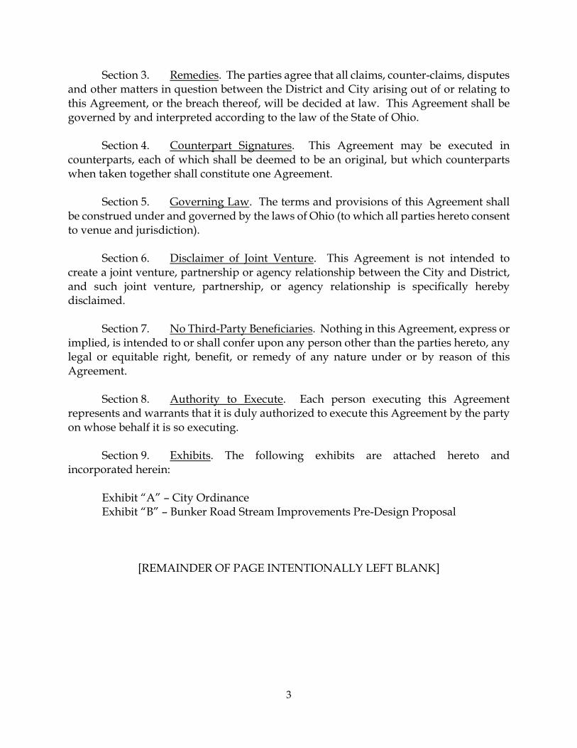
Section 3. Remedies. The parties agree that all claims, counter-claims, disputes and other matters in question between the District and City arising out of or relating to this Agreement, or the breach thereof, will be decided at law. This Agreement shall be governed by and interpreted according to the law of the State of Ohio.
Section 4. Counterpart Signatures. This Agreement may be executed in counterparts, each of which shall be deemed to be an original, but which counterparts when taken together shall constitute one Agreement.
Section 5. Governing Law. The terms and provisions of this Agreement shall
be construed under and governed by the laws of Ohio (to which all parties hereto consent to venue and jurisdiction).
Section 6. Disclaimer of Joint Venture. This Agreement is not intended to
create a joint venture, partnership or agency relationship between the City and District, and such joint venture, partnership, or agency relationship is specifically hereby disclaimed.
Section 7. No Third-Party Beneficiaries. Nothing in this Agreement, express or
implied, is intended to or shall confer upon any person other than the parties hereto, any legal or equitable right, benefit, or remedy of any nature under or by reason of this Agreement.
Section 8. Authority to Execute. Each person executing this Agreement
represents and warrants that it is duly authorized to execute this Agreement by the party on whose behalf it is so executing.
Section 9. Exhibits. The following exhibits are attached hereto and
incorporated herein: Exhibit “A” – City Ordinance Exhibit “B” – Bunker Road Stream Improvements Pre-Design Proposal
[REMAINDER OF PAGE INTENTIONALLY LEFT BLANK]

4
The parties hereto have executed and delivered this Agreement as of the date first above written.
NORTHEAST OHIO REGIONAL SEWER DISTRICT By: ____________________________________
Kyle Dreyfuss-Wells Chief Executive Officer
and: ___________________________________
Frank Greenland, P.E. Director of Watershed Programs
CITY OF NORTH ROYALTON By: Title: _____________________________________ The legal form and correctness of this instrument is approved. By: _______________________
Thomas A. Kelly Director of Law
Date: _____________________ This Instrument Prepared By: _________________________________ Katarina K. Waag Assistant General Counsel Northeast Ohio Regional Sewer District Each party agrees that this Agreement may be executed and distributed for signatures via email, and that the emailed signatures affixed by both parties to this Agreement shall have the same legal effect as if such signatures were in their originally written format.
5
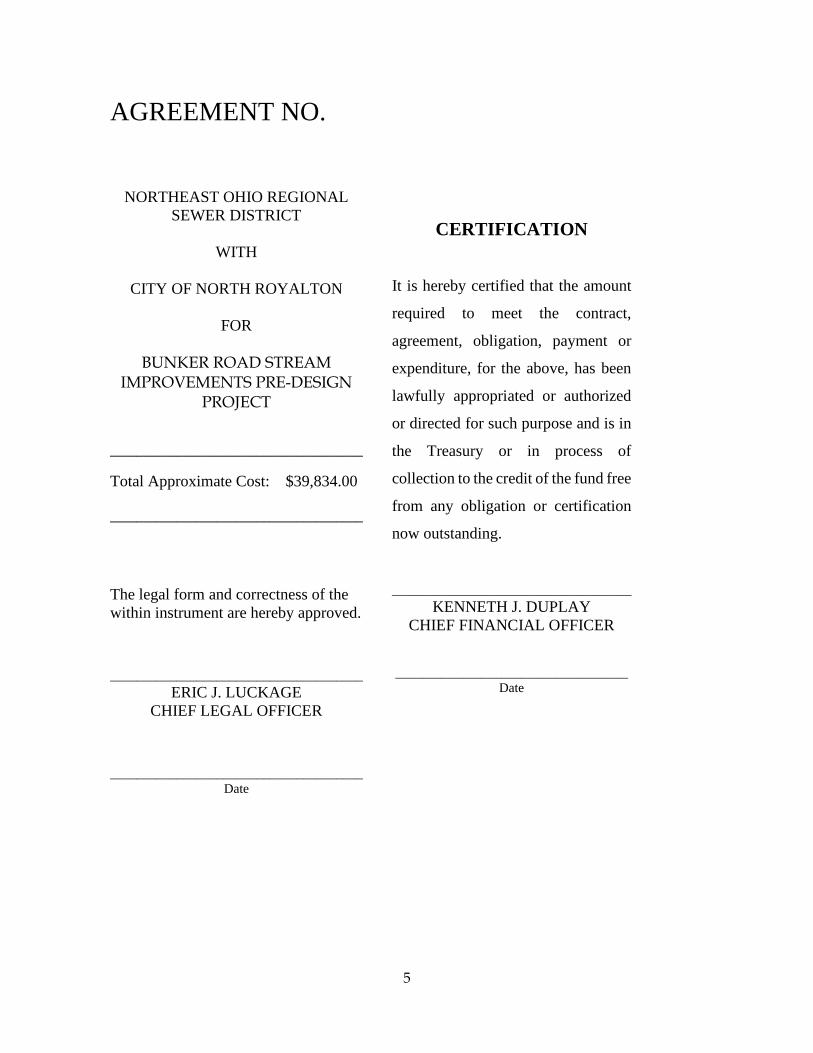
AGREEMENT NO.
NORTHEAST OHIO REGIONAL SEWER DISTRICT
WITH
CITY OF NORTH ROYALTON
FOR
BUNKER ROAD STREAM
IMPROVEMENTS PRE-DESIGN PROJECT
______________________________________ Total Approximate Cost: $39,834.00 ______________________________________ The legal form and correctness of the within instrument are hereby approved. ______________________________________
ERIC J. LUCKAGE CHIEF LEGAL OFFICER
______________________________________
Date
CERTIFICATION
It is hereby certified that the amount
required to meet the contract,
agreement, obligation, payment or
expenditure, for the above, has been
lawfully appropriated or authorized
or directed for such purpose and is in
the Treasury or in process of
collection to the credit of the fund free
from any obligation or certification
now outstanding.
____________________________________ KENNETH J. DUPLAY
CHIEF FINANCIAL OFFICER
___________________________________ Date

PREPARED FORCity of North Royalton
14600 State Rd.North Royalton, OH 44133
SUBMITTED 5.20.2021
Bunker Road Stream Improvements Pre-Design Proposal

page 1
Project Understanding This project, located in North Royalton, will analyze the area where a regional stream, part of the Big Creek watershed, NEORSD Asset ID BC00375, merges with a local stream north of Bunker Road, east of Ridgedale Road. The properties most directly affected are 6300 Bunker Road, PPN 48902015, and 6400 Bunker Road, PPN 48902026.
The analysis, aided by reference material provided by the Northeast Ohio Regional Sewer District (the DISTRICT), including a 2020 Field Inspection Report and Big Creek Main Branch SW Master Plan Model, will begin upstream of the two culverts under Bunker Road and continue north past the confluence of the streams.
The home at 6300 Bunker Road is bordered by the regional stream to the east and the local tributary on the west, with the two streams merging behind the home to the north. A six-foot-tall retaining wall frames the backyard on the east, west, and north sides. The retaining wall on the right bank of the local stream (west side of the property) has a six- inch-high by 24-inch-deep scour at the toe along the entire length. Additionally, a sinkhole has formed in the resident’s property measuring two feet wide, six feet long, and six feet in depth. On the left bank of the regional stream (east side of the property), the retaining wall has a six-inch-high by four-inch-deep scour along the entire length.
As the local stream passes through the culvert under Bunker Road at 6400 Bunker, the stream flow is blocked by a rock, forcing flow through the gabion baskets on the left bank adjacent to the residential driveway. The armored streambank approach, required to protect the home, appears to be failing.
Proper phasing of the project due to the presence of two streams, and the location of an eight-inch sanitary sewer from Bunker Road, traveling north under the local stream between 6300 and 6400 Bunker Road, must be considered.
This pre-design proposal will study the project area, identify obstacles and prepare conceptual alternatives to provide environmental sustainability for the project area.
Scope of Services Basis of Design Report (If Authorized)
CT Consultants (CT) shall furnish an initial Basis of Design Report (BODR) with a Technical Memorandum at the conclusion of the Pre-Design phase to verify the physical condition of the channels, a summary of dimensionless
ratios or a range of slopes and spacing for stable bank and channel features as well as all parameters, assumptions, calculations, and decisions used or made in revising and advancing the goals and objectives developed by the DISTRICT. CT will deliver, for DISTRICT review and approval, a BODR containing, at a minimum, the following information:
> Review/verification of the information contained in the Project Definition Reports
> Proposed channel profiles, dimensions and alignments
> Hydrologic assessment
> Hydraulic assessment data
> Geotechnical analysis data
> Geomorphic assessment
> Scour assessment data
> Selected design discharges and rationales
> Existing infrastructure and utilities
> Tree clearing limits
> Protection of utility crossings and/or outfalls within the project reaches
> Existing wetlands and threated/endangered species review
> Risk identification and mitigation strategies
CT will develop a number of alternatives for the project site as part of the BODR process. The first BODR submittal will include an Alternatives Analysis. CT will not continue with detailed design until the DISTRICT and CT have agreed upon the preferred alternative for the project site.
The BODR and Technical Memorandum will be updated, as required, at each successive deliverable phase. A final BODR will be submitted to the DISTRICT with the As-Built Plans.
Evaluation of Existing Information CT will evaluate and consider the following existing information related to the Scope of Services for the Project.
> Hydrologic and Hydraulic Modeling Data
> Historic Flow Data
> Ecological Assessment Report
> Stormwater Inspection and Maintenance Reports
> Existing condition reports/plans

page 2
> DISTRICT GIS Dataset
> DISTRICT’s Safety and Security Standards
> Structural analysis of two culverts (regional and local streams under Bunker Rd.)
CT will identify key design constraints and potential information gaps. Additional relevant data might be available from external sources, such as nearby stream gage data, OSIP LiDAR data, bridge inspection and maintenance reports, and historic aerial imagery. CT will coordinate with the DISTRICT for available information prior to pursuing any other resources.
Surveying
CT will gather horizontal and vertical data, using conventional ground survey methods, at strategic locations to create a one (1) foot contour interval map of the site. CT will locate natural and man-made features and existing site improvements in the area of the proposed survey limits (Exhibit A). The work will include surveying the items described below
> The channel centerline invert and cross-section shape are of particular interest for this project. Measure stream channel invert approximately every 50 feet, preferably at the upstream ends of the nearest riffle hard point on the channel bed. The limits of 50-foot cross-sections will begin 200 feet south of Bunker Road and continue 200 feet north of the confluence of the streams. Channel invert elevations are to be incorporated into the topographic contours and are required to provide accurate elevations for the channel centerline. The survey shall identify significant breaks in channel slope and tops of riffles and pool depths. Include channel invert elevations at the furthest upstream and downstream limits of the reaches. Channel cross sections shall be at 50-ft intervals or transition points and should also include top of the bank, toe of slope, and identification of walls or other structures in, and adjacent to, the channel.
> Edge of pavement and elevations of all roads within topographic survey area at a minimum of 50-ft intervals.
> We will set two (2) benchmarks, which will be established for future use. Each benchmark will be set in areas where site improvements are not anticipated and will be assigned horizontal and vertical data. These shall be established generally at the upstream limits and
downstream limits of the topographic survey area.
> We will uncover and locate the centerline and right- of-way monumentation required, but CT will not be independently retracing individual parcels except for the property lines within the project limits. We will supplement the adjoining property lines using the Cuyahoga County Geographical Information System (GIS). We will reestablish the right-of-way on Bunker Rd. We will not individually research any easements on the subject properties within the project limits.
> CT will contact the Ohio Utility Protection Service (OUPS) to request physical markings of publicly owned and franchise utilities along the proposed route, as well as request plans to be sent. CT’s Land Services will follow up with OUPS and Utility Companies to ensure utility maps are provided. Natural and man-made features will be located, to generally include but not limited to, above and underground observed utilities, power or light poles, and private and public drives, if sanitary or storm systems are observed, CT will attempt to gain access by way of manholes, to assess size and depth of sewer lines. The manholes must be readily available to be open and not be bolted shut or have a water-tight seal on them.
> Isolated trees with an excessive diameter (18 inches or greater at diameter at breast heights [dbh]) will be either individually located or the limits of heavily wooded areas located depending on site conditions (individual trees located will only be within the areas of potential construction).
Permits and Easements Coordination CT will identify permits and approvals required by public and private entities, including, but not limited to, the City of North Royalton (local floodplain development permit, Tree Removal Permit, etc.), Cuyahoga County, U.S. Army Corps of Engineers (USACE) (Section 404 Permit), Ohio EPA (OEPA) (Permit to Install, Storm Water Pollution Prevention Plan (SWPPP), Notice of Intent (NOI), 401 Water Quality Certification, etc.), Federal Emergency Management Agency (FEMA), and prepare information regarding the required permit processes, timelines and costs for inclusion in the Project Definition Memo (Task 13). Where necessary and with the approval of the DISTRICT PM, CT shall contact the appropriate regulatory agency to seek clarification on the applicability of permit requirements.

page 3
CT shall review and rely upon the Ecological Assessment Reports (provided by the DISTRICT) to determine the extent and quality of ecological resources (e.g., streams, wetlands, ponds, and threatened and endangered species habitat) present within the project areas for the purpose of determining the required permits and approvals. No additional field assessment of ecological resources will be completed by CT, with the exception of establishing the Ordinary High-Water Mark along both streams.
If elements of work are anticipated to require temporary or permanent easements, CT shall identify and coordinate these easements with the DISTRICT. If required, CT shall prepare mapped boundaries for up to two permanent and two temporary easements, which may be needed during construction. These mapped boundaries may be utilized by the DISTRICT for planning purposes in preliminary discussions with property owners but shall not include legal descriptions and exhibits. Preparation of final easement documents, including surveying services for boundaries, easement limits, etc., shall be provided as part of detailed design once the final locations and sizes of easements are determined.
CT makes the following data collection and environmental survey assumptions:
> No endangered species surveys or mussel surveys will be performed. This work, if required, will be provided by the DISTRICT.
> Cultural resources literature reviews and/or surveys will be provided by the DISTRICT.
> All permits and agency submittals will be prepared as part of the detailed design effort under a future scope of work.
> No Environmental Assessment, Environmental Impact Statement preparation services, or other National Environmental Policy Act (NEPA) documentation is required to be produced by CT. If this work is necessary, it will be performed by the DISTRICT.
Geotechnical Investigation The geotechnical scope covers the effort required to provide the final design for the proposed restoration and slope repair at the project location for the DISTRICT. The effort includes a subsurface investigation, laboratory
testing, evaluation, and geotechnical analysis, and design of alternatives to accommodate the proposed stream alignment and provide bank stability.
The following assumptions were used to develop the scope:
> Drilling of new borings and laboratory testing will be performed by a subcontractor. It is assumed that access to the proposed drilling sites will be provided by the DISTRICT and that no other special permission will be required. Soil and groundwater at the drill sites are assumed to be free of contamination, thus no special care, health and safety plan, and handling is needed during field operations and laboratory work.
> A conceptual understanding of the location and details for construction of stream bank stabilization, including sequence of the work, will be coordinated with others prior to performing the proposed field geotechnical work.
> CT will coordinate with the DISTRICT about the preferred alternatives to protect DISTRICT infrastructure. Potential alternatives that may impact geotechnical data collection activities will be coordinated.
Subsurface Exploration CT will determine the location and required amount of soil borings. The subsurface exploration tasks for the project will include the following:
> Drilling mobilization to perform the field exploratory studies at the test locations determined. Approximate locations will be provided by CT. CT will perform one-call utility location prior to performing the field work and will make minor adjustments if necessary, to avoid existing utilities. The location of proposed soil borings at both project sites is shown on exhibits prepared and provided to the DISTRICT along with this scope of services.
> Visual classifications and subsurface soil and groundwater characteristics of the retrieved soil samples and log of the borings during the field explorations will be provided.
> Each boring location shall include a reference stake placed as the drilling is completed with the boring number identified. Each reference stake shall be set to reference the ground elevation where depths measurements were taken for each boring location.
> GPS coordinates for each boring location will be recorded so ground surface elevations may be referenced from existing survey information.
page 4
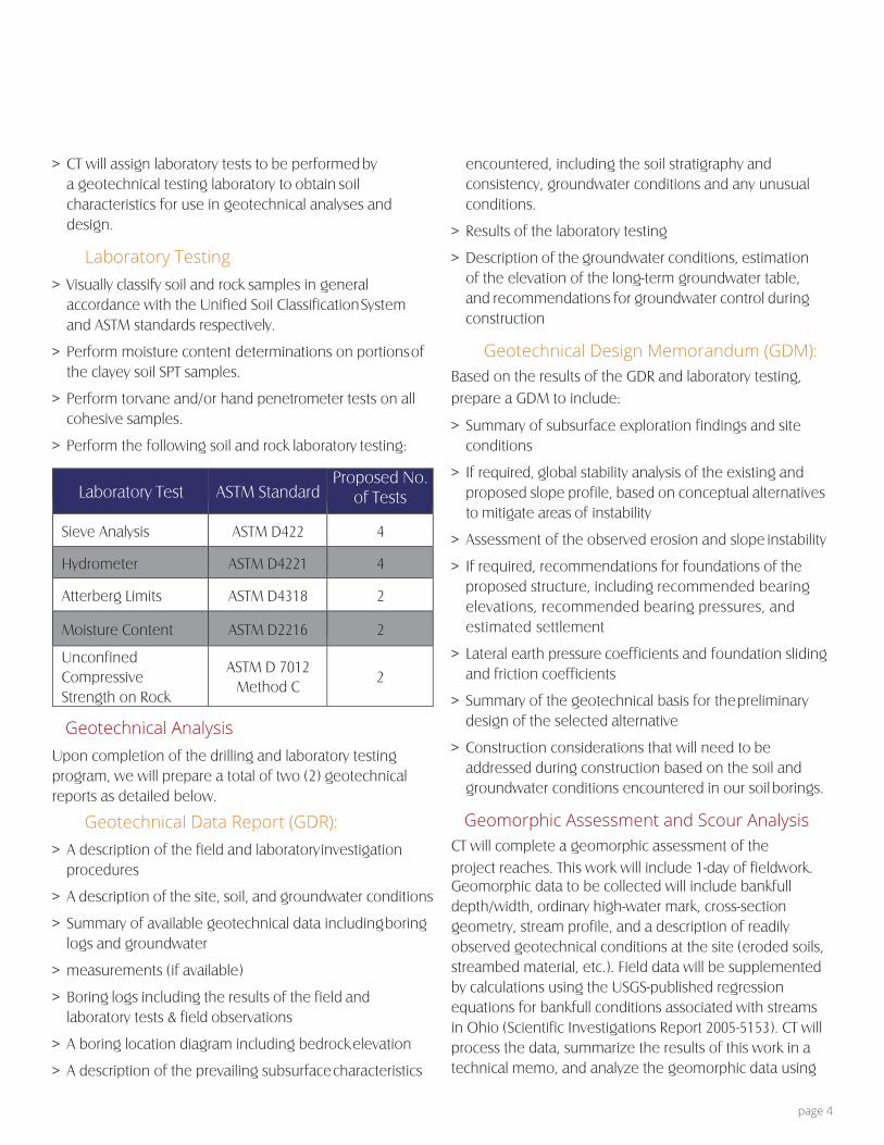
> CT will assign laboratory tests to be performed by a geotechnical testing laboratory to obtain soil characteristics for use in geotechnical analyses and design.
Laboratory Testing > Visually classify soil and rock samples in general
accordance with the Unified Soil Classification System and ASTM standards respectively.
> Perform moisture content determinations on portions of the clayey soil SPT samples.
> Perform torvane and/or hand penetrometer tests on all cohesive samples.
> Perform the following soil and rock laboratory testing:
Laboratory Test ASTM Standard Proposed No.
of Tests
Sieve Analysis ASTM D422 4
Hydrometer ASTM D4221 4
Atterberg Limits ASTM D4318 2
Moisture Content ASTM D2216 2
Unconfined Compressive Strength on Rock
ASTM D 7012 Method C
2
Geotechnical Analysis Upon completion of the drilling and laboratory testing program, we will prepare a total of two (2) geotechnical reports as detailed below.
Geotechnical Data Report (GDR): > A description of the field and laboratory investigation
procedures
> A description of the site, soil, and groundwater conditions
> Summary of available geotechnical data including boring logs and groundwater
> measurements (if available)
> Boring logs including the results of the field and laboratory tests & field observations
> A boring location diagram including bedrock elevation
> A description of the prevailing subsurface characteristics
encountered, including the soil stratigraphy and consistency, groundwater conditions and any unusual conditions.
> Results of the laboratory testing
> Description of the groundwater conditions, estimation of the elevation of the long-term groundwater table, and recommendations for groundwater control during construction
Geotechnical Design Memorandum (GDM): Based on the results of the GDR and laboratory testing, prepare a GDM to include:
> Summary of subsurface exploration findings and site conditions
> If required, global stability analysis of the existing and proposed slope profile, based on conceptual alternatives to mitigate areas of instability
> Assessment of the observed erosion and slope instability
> If required, recommendations for foundations of the proposed structure, including recommended bearing elevations, recommended bearing pressures, and estimated settlement
> Lateral earth pressure coefficients and foundation sliding and friction coefficients
> Summary of the geotechnical basis for the preliminary design of the selected alternative
> Construction considerations that will need to be addressed during construction based on the soil and groundwater conditions encountered in our soil borings.
Geomorphic Assessment and Scour Analysis CT will complete a geomorphic assessment of the project reaches. This work will include 1-day of fieldwork. Geomorphic data to be collected will include bankfull depth/width, ordinary high-water mark, cross-section geometry, stream profile, and a description of readily observed geotechnical conditions at the site (eroded soils, streambed material, etc.). Field data will be supplemented by calculations using the USGS-published regression equations for bankfull conditions associated with streams in Ohio (Scientific Investigations Report 2005-5153). CT will process the data, summarize the results of this work in a technical memo, and analyze the geomorphic data using

page 5
the latest version of RIVERMorphTM software or similar analysis. Assessments will be performed for stream bank erosion, near bank stress, shear stress, and velocity, as well as horizontal and vertical channel stability.
Hydraulic Analysis/Modeling
Hydraulic analysis will be performed utilizing the existing PCSWMM model of the BCEEAT system. The tasks included in this analysis will include the following:
• Review the existing modeling • Obtain additional storm events, if available, from
NEORSD. o Analysis should include the 1, 2, 5, 10, 25, 50,
100, and 500 year events to cover design needs as well as possible floodplain requirements since this area appears to have a Zone X estimated FEMA floodplain.
• Enhance the existing conditions with additional detail o Revise cross sections from detailed
topography survey from approximately 200 feet south of Bunker Road to approximately 200 feet north of the stream confluence.
o Provide additional cross sections to detail existing natural grade drops.
o Add cross sections and culvert details for the western stream. Additional sections will include from
approximately 200 feet south of Bunker Road to the stream confluence.
The existing subcatchment connection point for this stream will be changed to the upstream end of this addition.
• Review existing conditions model culverts and channels for various storm event conditions.
o Capacity o Velocity o Depth
• Develop proposed conditions models to present up to two alternatives for drainage channel improvements.
o Channel/overbank routing and widening o Culvert improvements
• Develop a technical memo of the hydraulic analysis results.
This hydraulic analysis will prepare the model for any necessary FEMA requirements, but only incudes analysis for design purposes and does not include any analysis for a FEMA LOMR submission. This area is only mapped as a Zone X FEMA floodplain, which is not considered a special flood hazard area.
Engineer’s Estimate of Probable Construction Cost
CT will include a Class 4 estimate in accordance with the Association for the Advancement of Cost Engineering (AACE) International Recommended Practice 18R-97. The cost estimate shall also be submitted in accordance with the DISTRICT’s design milestone cost-estimating guidelines. Three (3) copies and one (1) PDF electronic copy shall be submitted to the DISTRICT’s PM.
Constructability and Coordination Evaluations At the appropriate and agreed upon time, CT shall meet with the DISTRICT in an up-to-one-day workshop to discuss constructability and coordination items associated with the project elements. This workshop will include reviews of the anticipated means and methods for construction, staging area and access requirements, risk mitigation based on risks identified in the risk register, and approaches for the construction of the Project while keeping existing necessary infrastructure operating during construction. The workshop will also include reviewing any special construction materials and potential source locations, identifying preliminary work limits, and identifying real estate needs (acquisition, easement, or temporary work agreement).
The following items are associated with this Task:
> Workshop will be held at a DISTRICT facility and optionally include visit to the project sites for further discussion.
> Consultant will prepare an agenda and slide presentation to guide the workshop discussion.
> Consultant will provide appropriate graphic aids for reference throughout the workshop discussion.

page 6
Risk Analysis CT will perform continuous risk analysis for the Project. The risks and associated likelihood of occurrence as well as impact of occurrence will be summarized in a risk register template provided by the DISTRICT. The register will be reviewed at regular Project progress meetings.
Pre-Design Report The Pre-design Report will be prepared to summarize and document the pre-design activities. The report will include information related to the following:
> Description and assessment of exiting conditions.
> Summary of data collected.
» Existing Information
» Field Surveying
» Geotechnical Investigation
> Description of the geomorphic assessment and scour analysis
> Description of the hydraulic analysis
> Development and presentation of no more than two (2) conceptual alternatives for the protection of DISTRICT infrastructure and stream bank repair.
> An engineer’s opinion of probable construction cost meeting AACE Class 4 standards will be provided for each alternative.
> Alternative Comparison Matrix summarizing cost, benefits, risk, permitting, and real estate requirements associated with each conceptual alternative. No more than two (2) alternatives to mitigate areas of instability will be presented to the DISTRICT for the selection of the preferred one. CT will then proceed to design the selected alternative.
> Plan view conceptual drawings of each alternative, including preliminary plan, elevation view, and typical sectional details for the proposed alternatives.
It is assumed that a single alternative will be deemed suitable for advancement by the DISTRICT to advance to Detailed Design, following review and discussion with the DISTRICT.
Meetings CT will attend both internal and external meetings in
support of the Project. These meetings may include; internal design reviews, contract reviews, Board meetings, internal informational meetings and public meetings.
We have estimated four meetings for this task.
Deliverable and Data Standards All deliverables will be submitted in both PDF and native file format. In general, each deliverable will be provided as one optimized PDF document less than 100 MB. The PDF document will be indexed to match the table of contents or main sections of the document and provided as an unprotected or unsecured document. If the PDF document cannot be reduced to less than 100 MB, CT will develop an alternative submittal plan with the DISTRICT PM.
All submittals shall be provided to the DISTRICT PM electronically via upload to the District’s SharePoint site and one copy on electronic media such as USB drive or other media as approved by the DISTRICT PM. Media shall be labeled with NEORSD, Task/Project name, project number, and the name of the deliverable.
Schedule
Data Collection and Analysis 10 weeks
Develop Design Recommendations
4 weeks
Submit Draft Report 2 weeks
NEORSD Review 3 weeks
Submit Final Report 4 weeks
Total Anticipated Duration of Pre-design Phase
23 weeks
Fees and Billing CT will accomplish the Scope of Services for the following not-to- exceed fees:
Evaluation of Existing Information $ 11,080
Surveying $ 12,000
Permits and Easements $ 550
Geotechnical Investigation $ 3,300
Subsurface Exploration $ 3,000
Geotechnical Analysis $ 3,400
Geomorphic Assessment $ 770
Hydraulic Analysis/Modeling $ 20,080

page 7
Engineer’s Est. of Probable Construction Cost $ 2,880
Constructability Review $ 4,048
Risk Analysis $ 2,880
Pre-Design Report $ 13,080
Meetings $ 1,880
Total Base Fee $ 79,668
For this project, a Pre-Design Report, without a Basis of Design Report, may be sufficient. Therefore, the Basis of Design Report was not included in the Total Base Fee. If NEORSD deems it is necessary, it can be provided for the following additional fee:
Basis of Design Report $ 6,500
The above fee is subject to adjustment for changes in scope requested by the City and is not to be exceeded without further authorization. Any change from the proposed scope of services will require a change in authorized fee, whether such change increases or decreases the total proposed fee. Above fees do not include permitting fees payable to reviewing agencies.
Invoices will be submitted monthly. Invoices are due and payable within 30 days after receipt. If you concur with this proposal and desire us to proceed with the aforementioned work, the necessary Work Authorization will be prepared. This proposal will adhere to the Terms and Conditions on file with the City. Fees and times stated in this agreement are valid for 60 days from the date of this proposal.
Respectfully,
CT Consultants, Inc.
Justin Haselton, PE, CPESC, LEED AP City Engineer City of North Royalton

your trusted advisor1001 Lakeside Ave. E.
Suite 1005Cleveland, OH 44114
p: 216.430.8500f : 440.951.7487
www.ctconsultants.com