Project #4 - tonefiend.com Club Project 4 v03.pdf · ©2011 by Joe Gore tonefiend DIY CLUB...
36
©2011 by Joe Gore tonefiend DIY CLUB 1 Project #4 The Fiendmaster: A Dallas Rangemaster Spinoff v03, 02.20.12 Monday, February 20, 12
Transcript of Project #4 - tonefiend.com Club Project 4 v03.pdf · ©2011 by Joe Gore tonefiend DIY CLUB...

©2011 by Joe Gore
tonefiendDIY CLUB
1
Project #4The Fiendmaster:
A Dallas Rangemaster Spinoff
v03, 02.20.12
Monday, February 20, 12

©2011 by Joe Gore
tonefiendDIY CLUB
Introducing Project #4
This is a modernized version of the Dallas Rangemaster — the overdrive circuit that put the punch in a huge percentage of British rock in the years surrounding 1970. We’re talking Clapton, Page, May, Townshend, Bolan, Ronson, Iommi — those guys.
This is a relatively easy project, and a contender for a first build. Still, I recommend building Project #1 first, or at least reviewing it carefully, because it introduces many parts and build techniques used here.
On the other hand, if you’ve built pedals before, dive right in — the water is scalding!
But please read this document through before starting, since you’ll have several options along the way, and you may want to plan and choose parts accordingly.
2
Monday, February 20, 12
©2011 by Joe Gore
tonefiendDIY CLUB
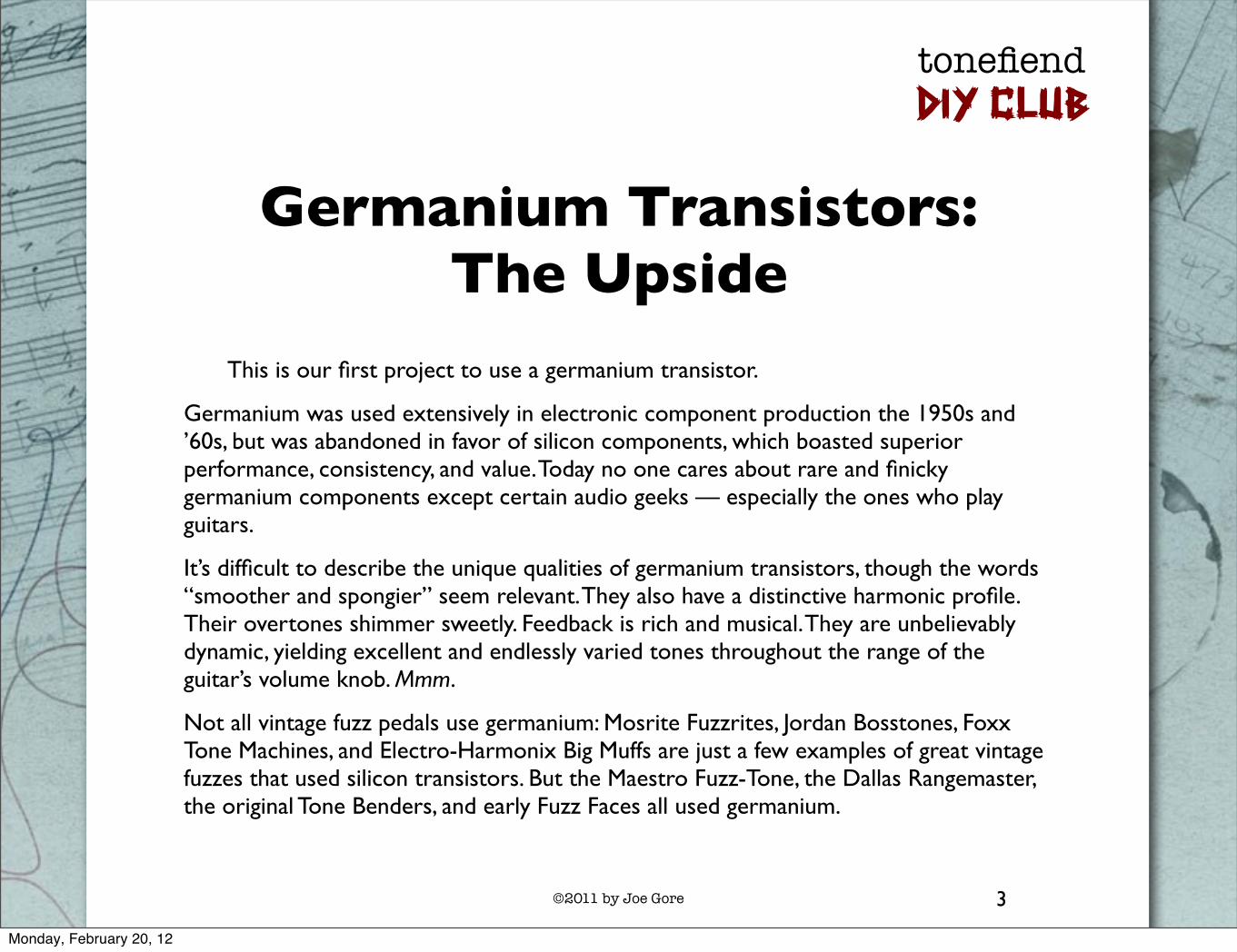
Germanium Transistors:The Upside
This is our first project to use a germanium transistor.
Germanium was used extensively in electronic component production the 1950s and ’60s, but was abandoned in favor of silicon components, which boasted superior performance, consistency, and value. Today no one cares about rare and finicky germanium components except certain audio geeks — especially the ones who play guitars.
It’s difficult to describe the unique qualities of germanium transistors, though the words “smoother and spongier” seem relevant. They also have a distinctive harmonic profile. Their overtones shimmer sweetly. Feedback is rich and musical. They are unbelievably dynamic, yielding excellent and endlessly varied tones throughout the range of the guitar’s volume knob. Mmm.
Not all vintage fuzz pedals use germanium: Mosrite Fuzzrites, Jordan Bosstones, Foxx Tone Machines, and Electro-Harmonix Big Muffs are just a few examples of great vintage fuzzes that used silicon transistors. But the Maestro Fuzz-Tone, the Dallas Rangemaster, the original Tone Benders, and early Fuzz Faces all used germanium.
3
Monday, February 20, 12

©2011 by Joe Gore
tonefiendDIY CLUB
Germanium components are usually available only from specialized distributors, who inevitably sell them for many times the cost of their silicon equivalents. (You can find a list of reliable vendors on the project page at tonefiend.com.)
There’s much variation in quality from germanium transistor to germanium transistor.
They’re noisy.
Their tone changes with the air temperature.
The vast majority of surviving germanium transistors are of the PNP variety, which means they’re engineered for positive-ground circuits, which were common in the ’60s, but nearly non-existent today. You can’t use a pedal with PNP transistors with a conventional negative-ground power supply unless you jigger with the schematic — which is exactly what we do here.
You can find NPN, i.e., negative-ground, germanium transistors, but they’re rarer and more expensive, and you generally have fewer models to choose from. If a) you dig the germanium sound, and b) might want to build more germanium-powered pedals in the future, I suggest getting into the PNP habit.
4
Germanium Transistors:The Downside
Monday, February 20, 12
©2011 by Joe Gore
tonefiendDIY CLUB
5
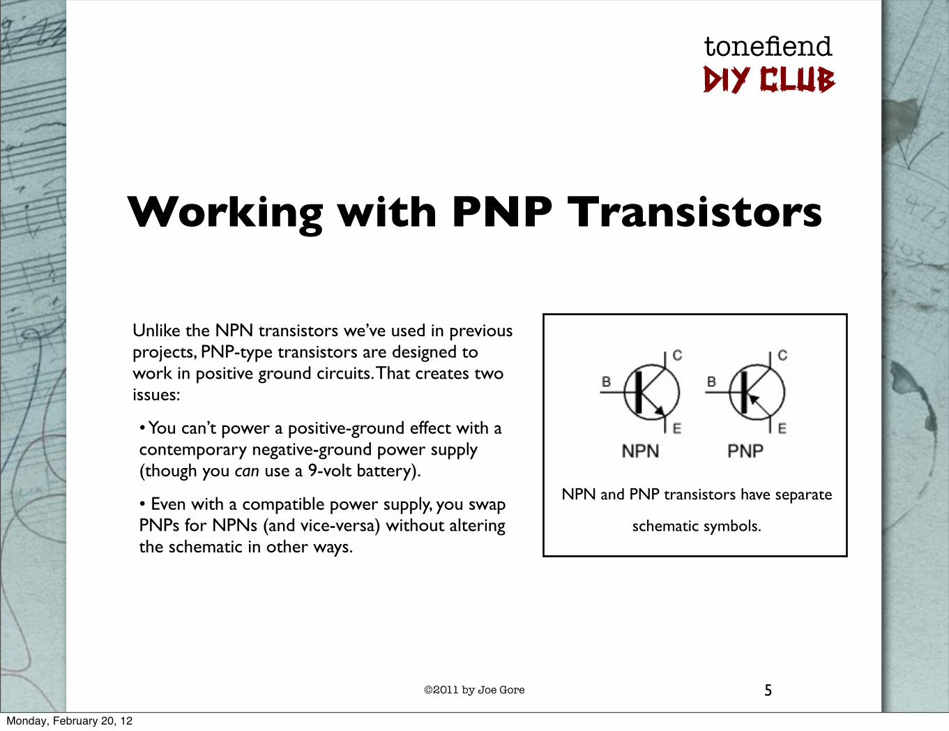
Working with PNP Transistors
Unlike the NPN transistors we’ve used in previous projects, PNP-type transistors are designed to work in positive ground circuits. That creates two issues:
• You can’t power a positive-ground effect with a contemporary negative-ground power supply (though you can use a 9-volt battery).
• Even with a compatible power supply, you swap PNPs for NPNs (and vice-versa) without altering the schematic in other ways.
NPN and PNP transistors have separate
schematic symbols.
Monday, February 20, 12

©2011 by Joe Gore
tonefiendDIY CLUB
6
The Original Schematic
Here’s something pretty close to the original Rangemaster schematic.
If you want to build a relatively faithful replica, work from this schematic, omit the DC adapter, and power it via battery only.
You can try this with any PNP germanium transistor. But the relatively common AC-128 will sound great here.
Monday, February 20, 12
©2011 by Joe Gore
tonefiendDIY CLUB
7
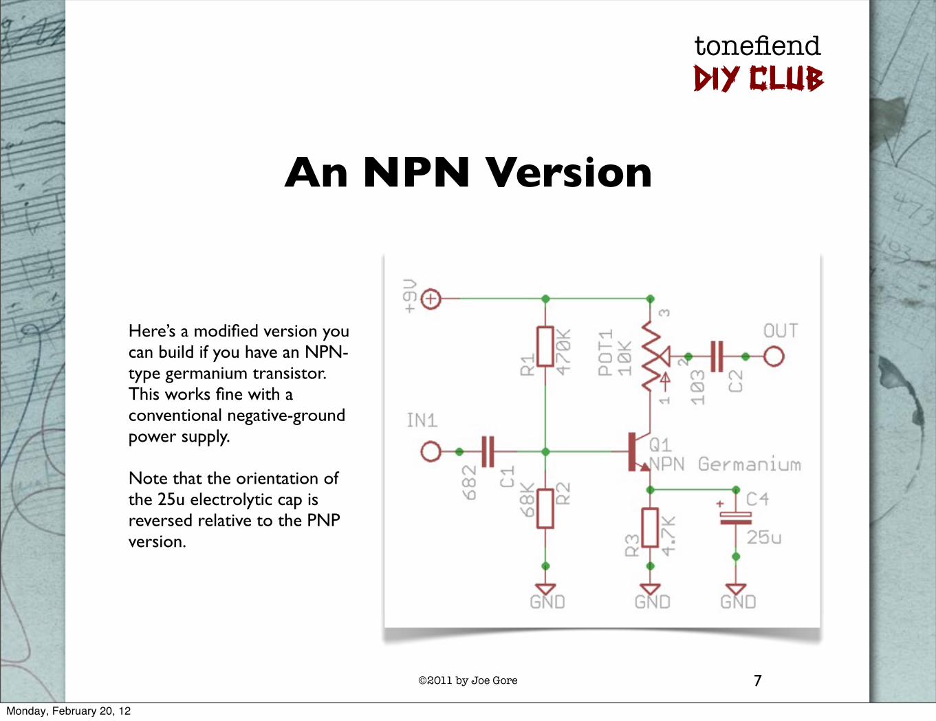
An NPN Version
Here’s a modified version you can build if you have an NPN-type germanium transistor. This works fine with a conventional negative-ground power supply.
Note that the orientation of the 25u electrolytic cap is reversed relative to the PNP version.
Monday, February 20, 12

©2011 by Joe Gore
tonefiendDIY CLUB
8
Our Project Schematic(basic version)
Here’s the version we’ll work with in the following pages.
To deploy a PNP transistor with a negative-ground power supply, we’ve reversed all the positive and negative connections in the circuit. The schematic is pretty much “upside down” relative to the original.
Other changes:
• I’ve swapped the 25u for a more common 22u, which has negligible sonic impact.
• The A50K pot provides a wider variety of sounds (including all the original ones).
• I prefer a 3.9K value for R3, but by all means, try the original 4.7K if you like.
Monday, February 20, 12

©2011 by Joe Gore
tonefiendDIY CLUB
9
The Transistor Pinout
B
C
E
Here’s the pinout for the AC128 transistor I used here. It’s the most common pinout for PNP germanium transistors.
If it doesn’t work, try swapping the collector and emitter wires. If that doesn’t work, find the pinout for your transistor online — just Google the part name plus “pinout.” And make sure you’re not using an NPN-type transistor.
Monday, February 20, 12
©2011 by Joe Gore
tonefiendDIY CLUB
10
Let’s Get Started!
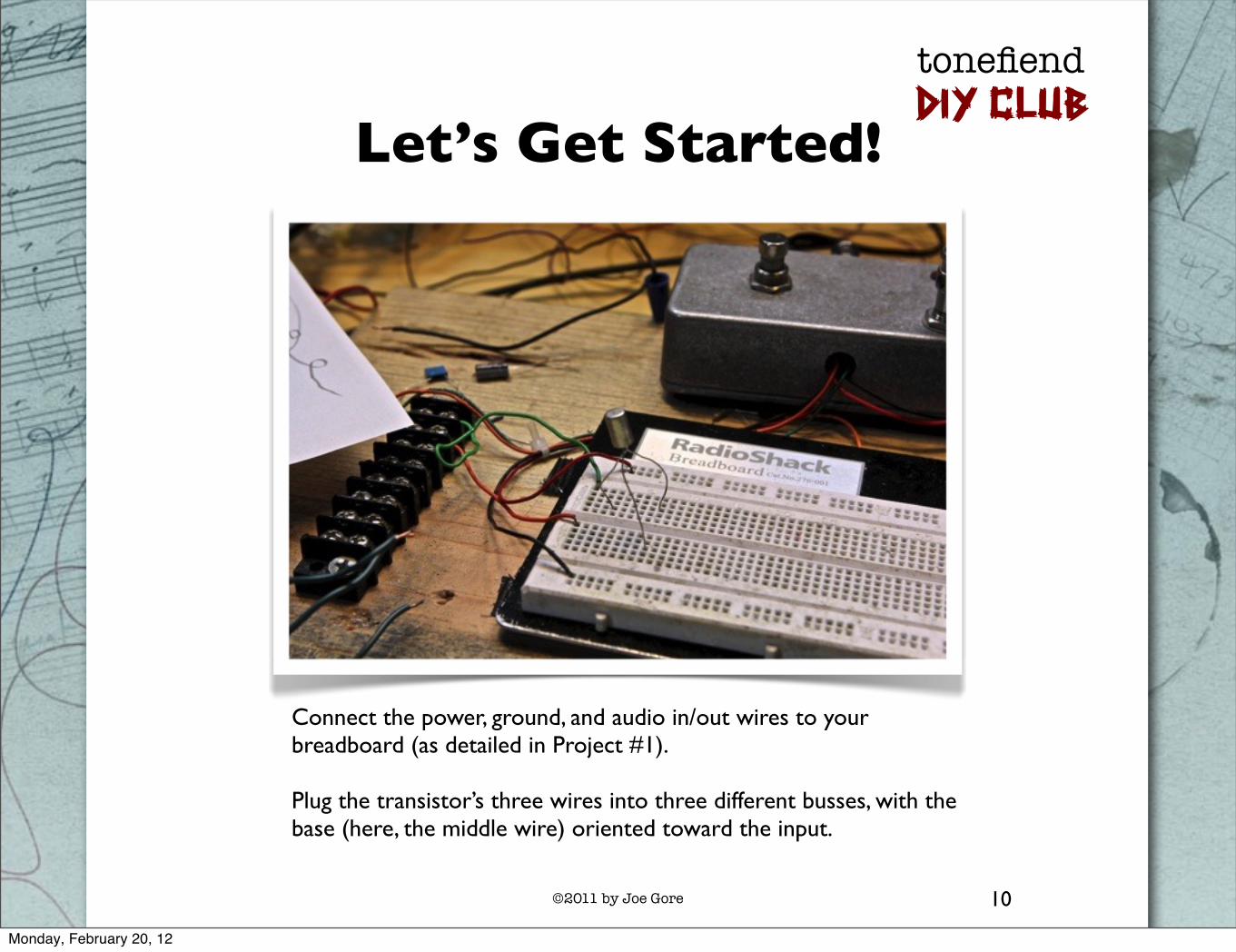
Connect the power, ground, and audio in/out wires to your breadboard (as detailed in Project #1).
Plug the transistor’s three wires into three different busses, with the base (here, the middle wire) oriented toward the input.
Monday, February 20, 12
©2011 by Joe Gore
tonefiendDIY CLUB
11
Connect the Transistor’s Base
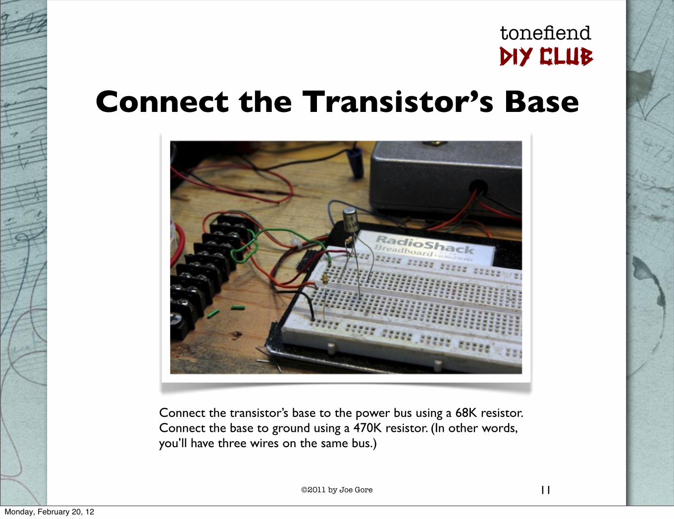
Connect the transistor’s base to the power bus using a 68K resistor. Connect the base to ground using a 470K resistor. (In other words, you’ll have three wires on the same bus.)
Monday, February 20, 12

©2011 by Joe Gore
tonefiendDIY CLUB
12
Connect the Collector
Connect the transistor collector to the power bus using a 3.9K resistor. Connect the same two points with a 22u electrolytic capacitor. (Again, you’ll now have three wires on the same bus.) As usual, the longer leg of the electrolytic cap connects to the power bus.
Monday, February 20, 12
©2011 by Joe Gore
tonefiendDIY CLUB
13
Wire Up Your Pots
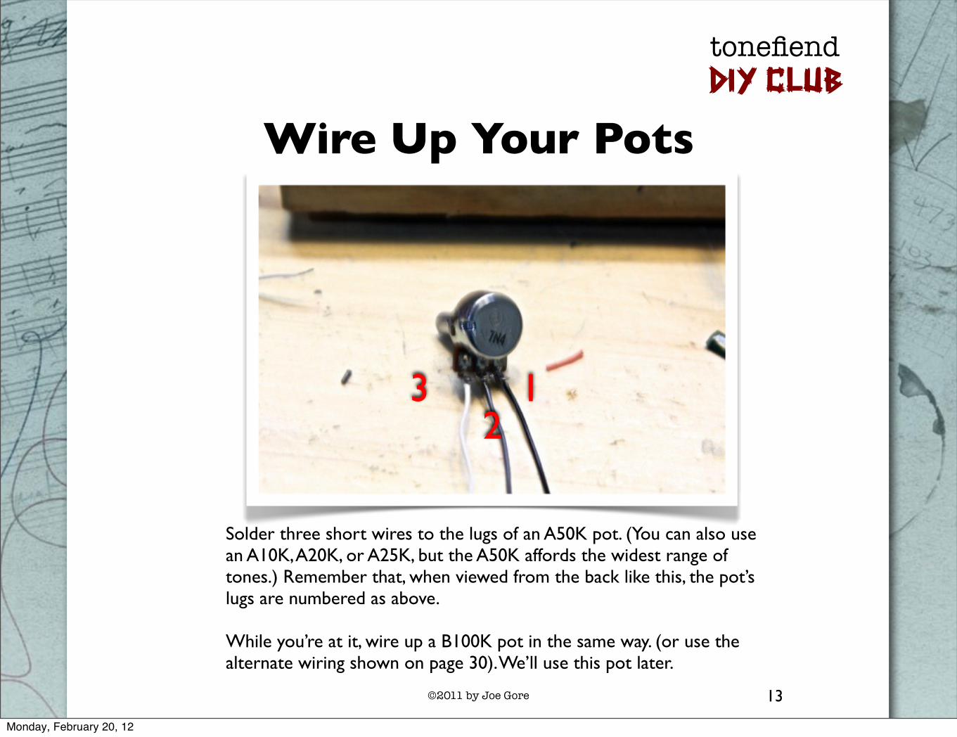
Solder three short wires to the lugs of an A50K pot. (You can also use an A10K, A20K, or A25K, but the A50K affords the widest range of tones.) Remember that, when viewed from the back like this, the pot’s lugs are numbered as above.
While you’re at it, wire up a B100K pot in the same way. (or use the alternate wiring shown on page 30). We’ll use this pot later.
3 12
Monday, February 20, 12

©2011 by Joe Gore
tonefiendDIY CLUB
14
Connect the Emitter to Ground
Connect lug 3 of the A50K pot to the transistor’s emitter. Connect lug 1 to ground. Place the wire from lug 2 into an empty bus.
Monday, February 20, 12

©2011 by Joe Gore
tonefiendDIY CLUB
15
Connect the Input to the Base
Use a 472 capacitor (also called a .0047uF or a 4.7n) to connect your input wire to the collector base. The base will now share a bus with three other wires.
Monday, February 20, 12

©2011 by Joe Gore
tonefiendDIY CLUB
16
Connect to the Output
Connect one leg of a 103 capacitor (also know as a .010uF and a 10n) to the A50K pot’s lug 2 wire. Connect the other leg of the cap to your output. (I used an orange jumper wire for this connection.)
Monday, February 20, 12

©2011 by Joe Gore
tonefiendDIY CLUB
17
About that Input Cap . . .
Turn up the A50K pot. You should now hear the pedal in action. The tone will be a bit trebly, with some of the resonant quality of a fixed wah pedal. Right now you’re pretty close to the tone of an original Rangemaster.
If the gain knob works opposite from how you want it, just reverse the wires from lugs 1 and 3. (In fact, you can do this anytime you want to reverse the action of a pot.)
The effect isn’t so much boosting treble as filtering out bass, and boosting what’s left.
The 472 capacitor (C1) is the filtering element. If you substitute a smaller-value cap, the tone gets even brighter and tinnier. If you use a larger value, less bass is removed. The tone not only gets bassier, but also louder and more distorted, because there’s more overall signal to drive the transistor.
Let’s try it out.
Monday, February 20, 12

©2011 by Joe Gore
tonefiendDIY CLUB
18
Substitute a Larger Input Cap
Replace the 472 input cap with the larger 104. The effect should become a much more loud, deep, and distorted. (Don’t be fooled by the physical cap size — the small blue cap in the pic above is actually of larger value than the fat gray one in the previous pics.)
Monday, February 20, 12

©2011 by Joe Gore
tonefiendDIY CLUB
19
Congrats! You’re a Musicologist!
You’ve just discovered an important link in the history of rock guitar. The emergence of heavy, power-rock guitar has a lot to do with Rangemasters modded with larger input caps for deeper, more distorted tones.
Metal starts here.
Monday, February 20, 12

©2011 by Joe Gore
tonefiendDIY CLUB
20
Input Cap Options
You can try different input caps here. The most common values between the 472 and 104 are (in ascending order), 682, 103, 223, 473, and 683. Maybe you’ll find one that’s perfect for you. (You could also go larger than 104 with a 224 or 474, but in my experience, that extra bass just makes everything sloppy.)
Or why not make it adjustable? You could switch between two favorite values with a SPDT switch, or many values using a rotary switch.
Better yet: let’s add another pot to fade between the thin, trebly 472 and the beefy 104.
Monday, February 20, 12
©2011 by Joe Gore
tonefiendDIY CLUB
21
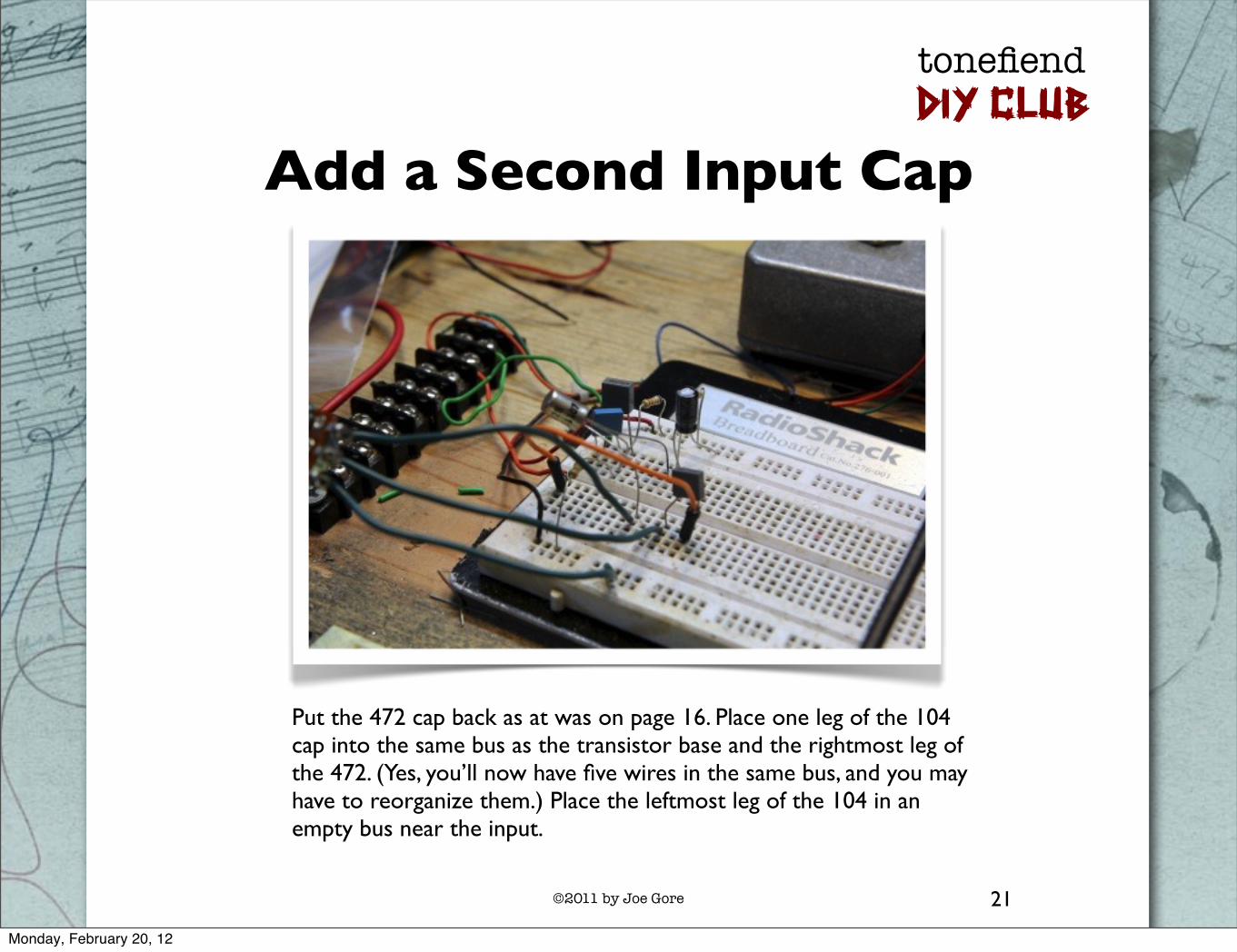
Add a Second Input Cap
Put the 472 cap back as at was on page 16. Place one leg of the 104 cap into the same bus as the transistor base and the rightmost leg of the 472. (Yes, you’ll now have five wires in the same bus, and you may have to reorganize them.) Place the leftmost leg of the 104 in an empty bus near the input.
Monday, February 20, 12

©2011 by Joe Gore
tonefiendDIY CLUB
22
Add a Tone Pot
Place the wires from lugs 2 and 3 of the B100K pot you prepared on page 13 in the same bus as your input wire. Place the wire from lug 1 on the same bus as the leftmost leg of the 104 cap.
Now the distortion tone should thin out as you advance the pot. If you’d like this control to work the other way around, just swap the wires from lugs 1 and 3. Your final pedal will sound like this.
Monday, February 20, 12
©2011 by Joe Gore
tonefiendDIY CLUB
23
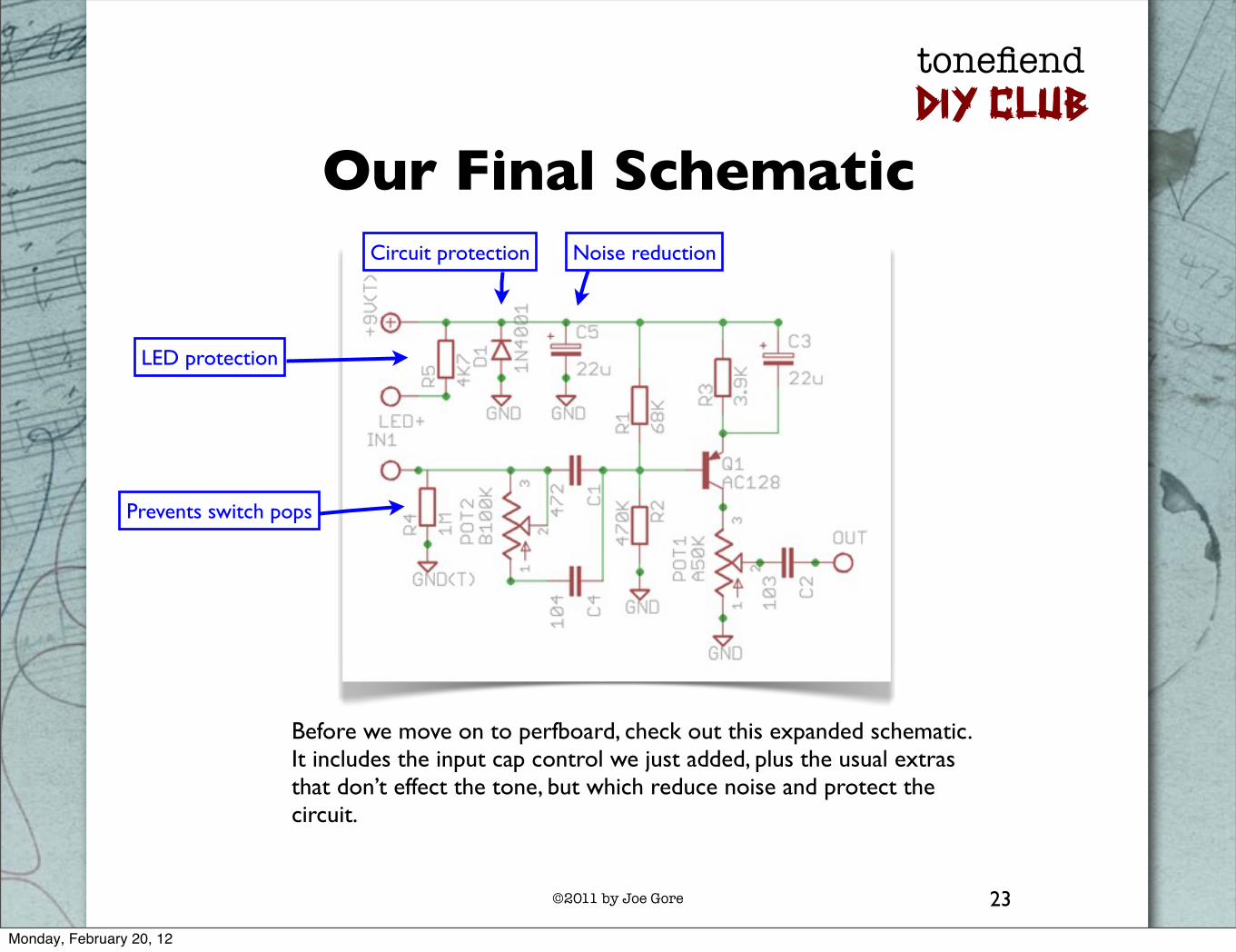
Our Final Schematic
Before we move on to perfboard, check out this expanded schematic. It includes the input cap control we just added, plus the usual extras that don’t effect the tone, but which reduce noise and protect the circuit.
LED protection
Prevents switch pops
Circuit protection Noise reduction
Monday, February 20, 12

©2011 by Joe Gore
tonefiendDIY CLUB
24
Start Perfboarding!
Prepare a piece of perfboard about this size. Strip several inches from a pair of wires and solder them loosely in place for your positive and negative busses.
Monday, February 20, 12

©2011 by Joe Gore
tonefiendDIY CLUB
25
To Socket or Not to Socket?
Here I’ve used a piece of SIP socket to house the transistor. The advantage: You can audition different transistors after the circuit is built, and you don’t have to solder the relatively fragile and valuable germanium transistor. It’s a major pain unsoldering anything from perfboard if you install it incorectly!
On the other hand, it’s easier to solder the long wire legs of the transistor than the small nubs on the reverse side of the socket material. Your call.
Either way, connect one leg of R1 to the positive bus, one leg of R2 to the negative bus, and one leg of each to the middle pin of the socket or transistor base.
Monday, February 20, 12

©2011 by Joe Gore
tonefiendDIY CLUB
26
Connect the Dual Input Caps
Connect the rightmost legs of C1 and C4 to the middle socket pin. Place the leftmost legs in two adjacent columns as shown.
Monday, February 20, 12
©2011 by Joe Gore
tonefiendDIY CLUB
27
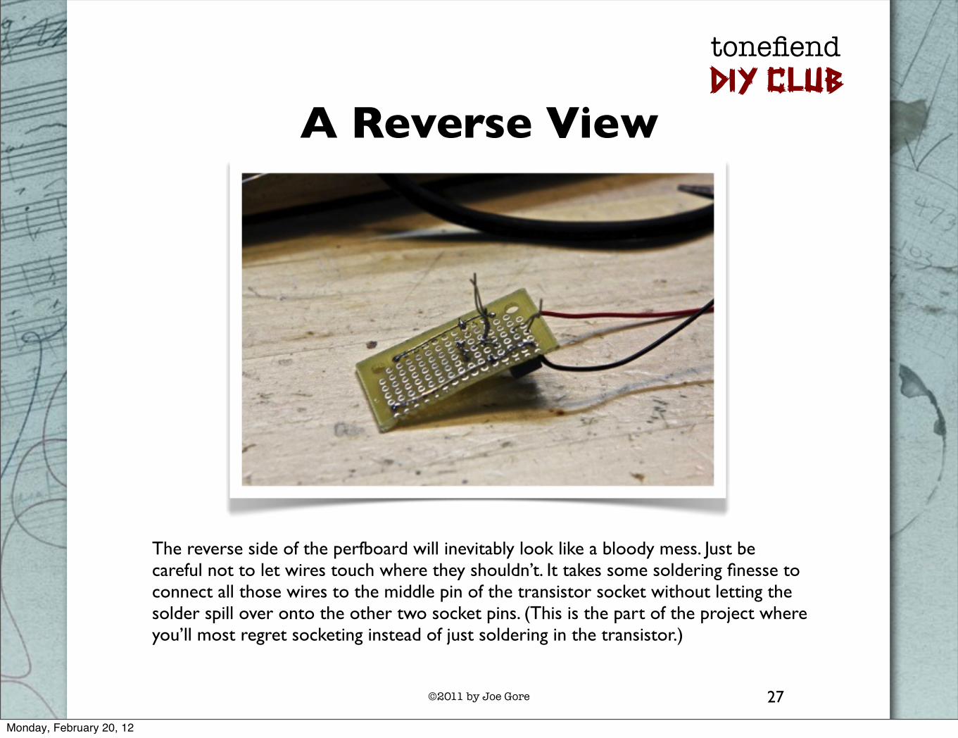
A Reverse View
The reverse side of the perfboard will inevitably look like a bloody mess. Just be careful not to let wires touch where they shouldn’t. It takes some soldering finesse to connect all those wires to the middle pin of the transistor socket without letting the solder spill over onto the other two socket pins. (This is the part of the project where you’ll most regret socketing instead of just soldering in the transistor.)
Monday, February 20, 12
©2011 by Joe Gore
tonefiendDIY CLUB
28
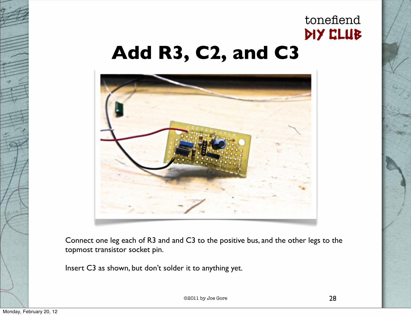
Add R3, C2, and C3
Connect one leg each of R3 and and C3 to the positive bus, and the other legs to the topmost transistor socket pin.
Insert C3 as shown, but don’t solder it to anything yet.
Monday, February 20, 12
©2011 by Joe Gore
tonefiendDIY CLUB
29
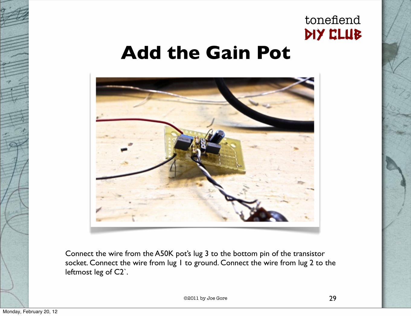
Add the Gain Pot
Connect the wire from the A50K pot’s lug 3 to the bottom pin of the transistor socket. Connect the wire from lug 1 to ground. Connect the wire from lug 2 to the leftmost leg of C2`.
Monday, February 20, 12

©2011 by Joe Gore
tonefiendDIY CLUB
30
Optional Tone Pot Wiring
There’s another way you can wire the B100K tone pot: Since both lugs 2 and 3 connect to the same destination, you can make the connection right on the pot, threading a stripped length of wire through both lugs and soldering it in place. That way, you only have to place two wires on the crowded perfboard. Again, your call.
Monday, February 20, 12

©2011 by Joe Gore
tonefiendDIY CLUB
31
Adding the Tone Pot
Whether you use two tone pot wires or three, connect lugs 3 and 2 to the leftmost leg of the 472 cap (C1). Attach an input wire to the same location. Connect the lug 1 wire to the leftmost leg of the 104 cap (C4).
Monday, February 20, 12
©2011 by Joe Gore
tonefiendDIY CLUB
32
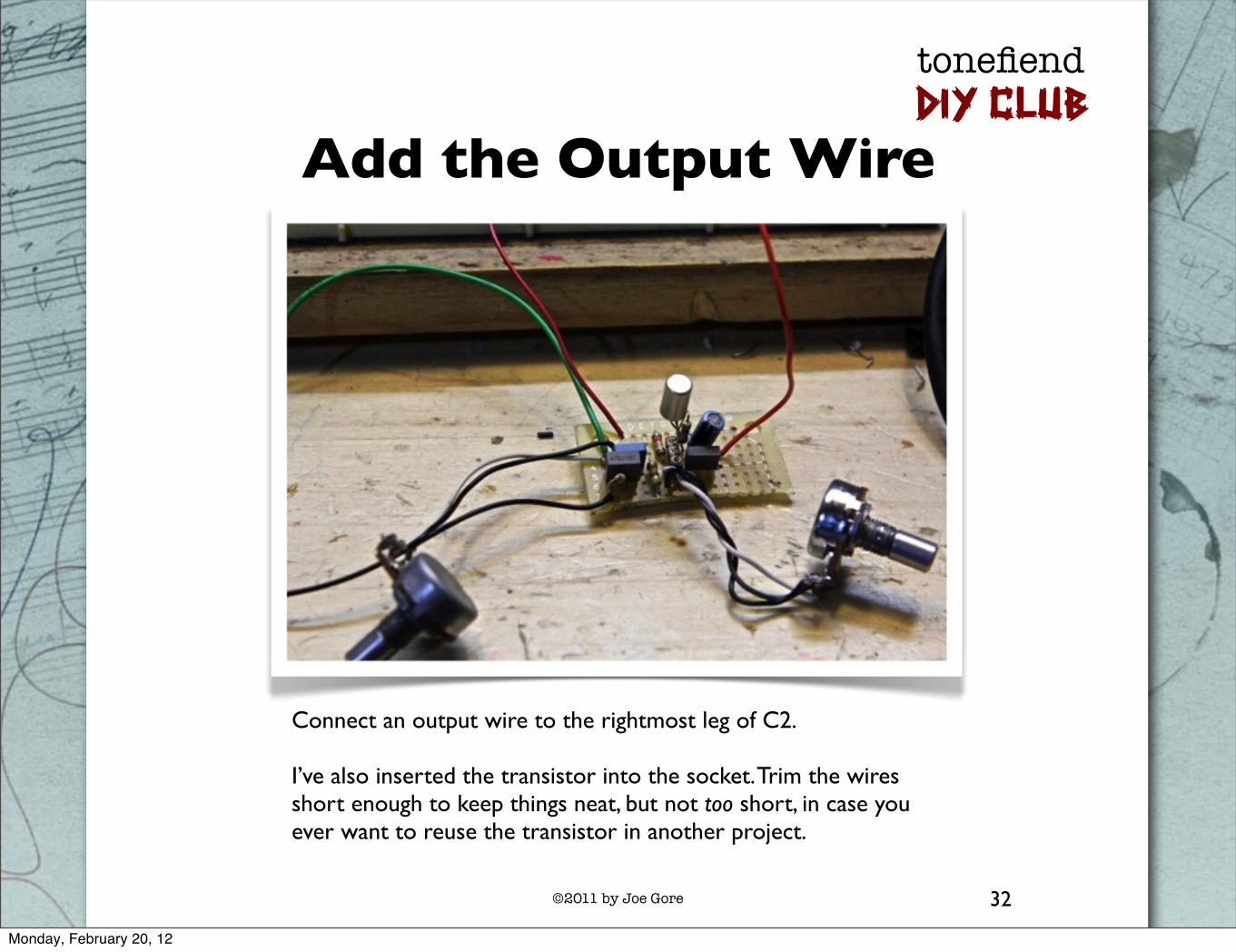
Add the Output Wire
Connect an output wire to the rightmost leg of C2.
I’ve also inserted the transistor into the socket. Trim the wires short enough to keep things neat, but not too short, in case you ever want to reuse the transistor in another project.
Monday, February 20, 12

©2011 by Joe Gore
tonefiendDIY CLUB
33
Add the Extras
Connect the 1M resistor (R4) between the cluster of wires at the input and ground. Place the other 22u electrolytic cap (C5) between the positive and negative busses. Place the 1N4001 diode (which I cleverly forgot to include in this photo) alongside it, with the banded end connected to the positive bus.
R4
C3
Monday, February 20, 12

©2011 by Joe Gore
tonefiendDIY CLUB
34
Add the LED wiring
Connect one end of the 4.7K resistor (R5) to the positive bus. Tuck the other end of the resistor into a nearby hole, and attach it to a new wire, which will eventually connect to the positive leg of the power indicator LED.
R5
Blue wire will connect to positive
leg of LED
Monday, February 20, 12

©2011 by Joe Gore
tonefiendDIY CLUB
35
Box It Up!
Install your circuit in the enclosure.
Project #1 includes step-by-step boxing instructions. The procedure is exactly the same here.
If the pedal stops working only when you screw down the back of the enclosure, something is probably shorting. You can apply bits of double-sided tape to trouble spots.
You should now have a ridiculously great-sounding pedal.
If not, post your problem to tonefiend.com’s Project #4 thread. Chances are someone can help!
Monday, February 20, 12

©2011 by Joe Gore
tonefiendDIY CLUB
What could possibly go wrong?
tonefiend.com
Monday, February 20, 12