
Proile Rail Guide Slides - SKF Design and characteristic features General Guide SKF proile rail...
32
Proile Rail Guide Slides
Transcript of Proile Rail Guide Slides - SKF Design and characteristic features General Guide SKF proile rail...

Proile Rail Guide Slides
2
The SKF brand now stands for more than ever before, and means more to you as a valued customer.While SKF maintains its leadership as the hallmark of quality bearings throughout the world, new dimensions in technical advances, product support and services have evolved SKF into a truly solutions-oriented supplier, creating greater value for customers.These solutions encompass ways to bring greater productivity to customers, not only with breakthrough applica-tion-speciic products, but also through leading-edge design simulation tools and consultancy services, plant asset eficiency maintenance programmes, and the industry’s most advanced supply management techniques.The SKF brand still stands for the very best in rolling bearings, but it now stands for much more.SKF – the knowledge engineering company
3
Table of contentDesign and characteristic features4 General4 Guide5 Load carrying capacity of slides6 Drive: Slides with ball screw drive7 Drive: Slides with linear motor drive8 Cover8 Precision classes9 Stroke9 Materials9 Permissible operating temperatures9 Lubrication9 Load carrying capacity and life9 AccessoriesDimensional tables LTB10 LTB 110.L1.SD/TN12xx-BL: Slides with ball screw drive, with or without bellows11 LTB 110.L1.SD/TN12xx-SC: Slides with ball screw drive and steel cover12 LTB 170.L1.SD/TN16xx-BL: Slides with ball screw drive, with or without bellows13 LTB 170.L1.SD/TN16xx-SC: Slides with ball screw drive and steel cover14 LTB 235.L1.SX/TN/TL25xx-BL: Slides with ball screw drive, with or without bellows16 LTB 235.L1.SX/TN/TL25xx-SC: Slides with ball screw drive and steel cover18 LTB 320.L1.SX/TN/TL32xx-BL: Slides with ball screw drive, with or without bellows19 LTB 320.L1.SX/TN/TL32xx-SC: Slides with ball screw drive and steel cover20 LTB 400.L1.SX/TN/TL40xx-BL: Slides with ball screw drive, with or without bellowsDimensional tables LTS21 LTS 154.L1.1FN3-050-xK: Slides with linear motor drive, with or without bellows22 LTS 182.L1.1FN3-100-xK: Slides with linear motor drive, with or without bellows23 LTS 212.L1.1FN3-150-xK: Slides with linear motor drive, with or without bellowsSpeciication sheet24 Speciication sheet for the selection of proile rail guide slides27 Examples of possible axes conigurationsOrder code28 Order code LTB29 Order code LTS

4
Design and characteristic features
General GuideSKF proile rail guide slides are state-of-the-art slides with high load carrying capacity and high accuracy. Sizes SKF proile rail guide slides with ball screw drive are available in widths of 110, 170, 235, 320 and 400 mm. SKF proile rail guide slides with linear motor drive can be supplied in widths of 154, 182 and 212 mm.DrivesSKF proile rail guide slides are avail-able with ball screw drive and linear motor drive.
CoverThe proile rail guide slides can be supplied in three different versions: without cover, with bellows and with steel cover (ball screw drive only).Precision classesThe proile rail guide slides can be supplied in different precision classes depending on the respective applica-tion demands:P5, P2, (ball screw drive)P2 (linear motor drive)Customer beneitsModular and compact design• Variants having high load carrying • capacity and stiffnessWide variety of drive options, pro-• viding the optimum solution for any applicationDifferent covers to suit the ambient • conditionsCost optimization due to selection • of required precision class
SKF proile rail guide slides are equipped with a pair of proile rails itted with a total of four carriages (with the exception of size 212 with linear motor 1FN3-150-3K which has six carriages). Customer beneitProile rail guide with high load car-• rying capacity and stiffness
Refer to table 1 for further technical information.
Proile rail guide slide with linear motorProile rail guide slide with ball screw drive
5
Design and characteristic features
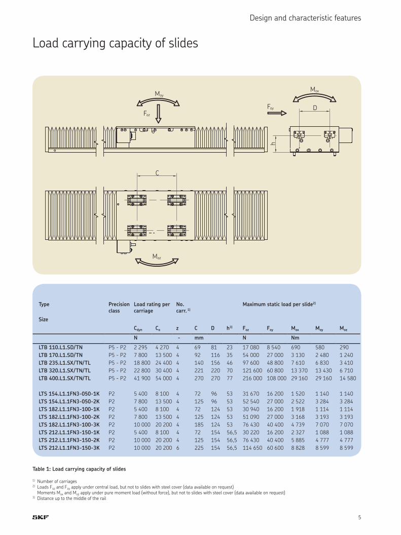
Load carrying capacity of slides
C
D
h
Moy
Foz
Mox
Foy
Moz
Table 1: Load carrying capacity of slides
1) Number of carriages2) Loads Foz and Foy apply under central load, but not to slides with steel cover (data available on request) Moments Mox and Moz apply under pure moment load (without force), but not to slides with steel cover (data available on request)3) Distance up to the middle of the rail
Type Precision class
Load rating per carriage
No. carr. 1)
Maximum static load per slide2)
Size
Cdyn Co z C D h3) Foz Foy Mox Moy Moz
N - mm N Nm
LTB 110.L1.SD/TN P5 - P2 2 295 4 270 4 69 81 23 17 080 8 540 690 580 290
LTB 170.L1.SD/TN P5 - P2 7 800 13 500 4 92 116 35 54 000 27 000 3 130 2 480 1 240LTB 235.L1.SX/TN/TL P5 - P2 18 800 24 400 4 140 156 46 97 600 48 800 7 610 6 830 3 410LTB 320.L1.SX/TN/TL P5 - P2 22 800 30 400 4 221 220 70 121 600 60 800 13 370 13 430 6 710LTB 400.L1.SX/TN/TL P5 - P2 41 900 54 000 4 270 270 77 216 000 108 000 29 160 29 160 14 580LTS 154.L1.1FN3-050-1K P2 5 400 8 100 4 72 96 53 31 670 16 200 1 520 1 140 1 140LTS 154.L1.1FN3-050-2K P2 7 800 13 500 4 125 96 53 52 540 27 000 2 522 3 284 3 284LTS 182.L1.1FN3-100-1K P2 5 400 8 100 4 72 124 53 30 940 16 200 1 918 1 114 1 114LTS 182.L1.1FN3-100-2K P2 7 800 13 500 4 125 124 53 51 090 27 000 3 168 3 193 3 193LTS 182.L1.1FN3-100-3K P2 10 000 20 200 4 185 124 53 76 430 40 400 4 739 7 070 7 070LTS 212.L1.1FN3-150-1K P2 5 400 8 100 4 72 154 56,5 30 220 16 200 2 327 1 088 1 088LTS 212.L1.1FN3-150-2K P2 10 000 20 200 4 125 154 56,5 76 430 40 400 5 885 4 777 4 777LTS 212.L1.1FN3-150-3K P2 10 000 20 200 6 225 154 56,5 114 650 60 600 8 828 8 599 8 599
6
Design and characteristic features
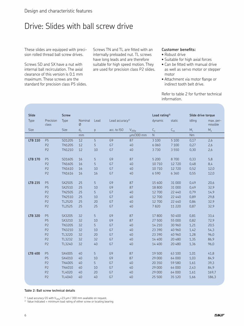
These slides are equipped with preci-sion rolled thread ball screw drives. Screws SD and SX have a nut with internal ball recirculation. The axial clearance of this version is 0.1 mm maximum. These screws are the standard for precision class P5 slides.
Screws TN and TL are itted with an internally preloaded nut. TL screws have long leads and are therefore suitable for high speed motion. They are used for precision class P2 slides.
Customer beneits:Robust drive• Suitable for high axial forces• Can be itted with manual drive • as well as servo motor or stepper motor Attachment via motor lange or • indirect tooth belt drive. Refer to table 2 for further technical information.
Drive: Slides with ball screw drive
Table 2: Ball screw technical details
1) Lead accuracy G5 with V300p=23 µm / 300 mm available on request.2) Value indicated = minimum load rating of either screw or locating bearing
Slide Screw Load rating2) Slide drive torque
Type Precision class Type Nominal Ø
Lead Lead accuracy1) dynamic static idling max. per-missibleSize Size do p acc. to ISO V300p Ca Coa Ms Ma
mm µm/300 mm N NmLTB 110 P5 SD1205 12 5 G9 87 3 100 5 100 0,17 2,6
P2 TN1205 12 5 G7 40 6 060 7 100 0,27 2,6P2 TN1210 12 10 G7 40 3 730 3 550 0,30 2,6
LTB 170 P5 SD1605 16 5 G9 87 5 200 8 700 0,33 5,8P2 TN1605 16 5 G7 40 10 710 12 720 0,48 8,4P2 TN1610 16 10 G7 40 10 710 12 720 0,52 12,0P2 TN1616 16 16 G7 40 6 590 6 360 0,55 12,0
LTB 235 P5 SX2505 25 5 G9 87 15 600 31 000 0,49 20,6P5 SX2510 25 10 G9 87 18 800 31 000 0,49 32,9P2 TN2505 25 5 G7 40 12 700 22 440 0,79 14,9P2 TN2510 25 10 G7 40 12 700 22 440 0,89 29,8P2 TL2520 25 20 G7 40 12 700 22 440 0,86 32,9P2 TL2525 25 25 G7 40 7 820 11 220 0,87 32,9
LTB 320 P5 SX3205 32 5 G9 87 17 800 50 400 0,81 33,4P5 SX3210 32 10 G9 87 27 500 55 000 0,82 72,9P2 TN3205 32 5 G7 40 14 210 30 960 1,21 20,5P2 TN3210 32 10 G7 40 23 390 40 960 1,42 54,3P2 TL3220 32 20 G7 40 23 390 40 960 1,28 96,0P2 TL3232 32 32 G7 40 14 400 20 480 1,35 86,9P2 TL3240 32 40 G7 40 14 400 20 480 1,36 96,0
LTB 400 P5 SX4005 40 5 G9 87 19 500 63 100 1,01 41,8P5 SX4010 40 10 G9 87 29 000 64 000 1,03 84,9P2 TN4005 40 5 G7 40 20 350 59 580 1,61 39,3P2 TN4010 40 10 G7 40 29 000 64 000 2,43 84,9P2 TL4020 40 20 G7 40 29 000 64 000 1,61 169,7P2 TL4040 40 40 G7 40 25 500 35 120 1,66 186,3
7
Design and characteristic features
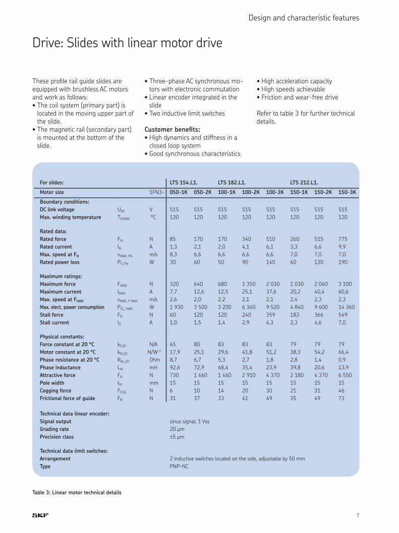
Drive: Slides with linear motor driveThese proile rail guide slides are equipped with brushless AC motors and work as follows:The coil system (primary part) is • located in the moving upper part of the slide.The magnetic rail (secondary part) • is mounted at the bottom of the slide.
Three-phase AC synchronous mo-• tors with electronic commutationLinear encoder integrated in the • slideTwo inductive limit switches• Customer beneits:High dynamics and stiffness in a • closed loop systemGood synchronous characteristics•
High acceleration capacity• High speeds achievable• Friction and wear-free drive• Refer to table 3 for further technical details.
For slides: LTS 154.L1. LTS 182.L1. LTS 212.L1.
Motor size 1FN3- 050-1K 050-2K 100-1K 100-2K 100-3K 150-1K 150-2K 150-3K
Boundary conditions:
DC link voltage UZK V 515 515 515 515 515 515 515 515
Max. winding temperature TP,MAX °C 120 120 120 120 120 120 120 120
Rated data:
Rated force FN N 85 170 170 340 510 260 515 775
Rated current IN A 1,3 2,1 2,0 4,1 6,1 3,3 6,6 9,9Max. speed at FN vMAX, FN m/s 8,3 6,6 6,6 6,6 6,6 7,0 7,0 7,0Rated power loss PV, FN W 30 60 50 90 140 60 130 190
Maximum ratings:
Maximum force FMAX N 320 640 680 1 350 2 030 1 030 2 060 3 100Maximum current IMAX A 7,7 12,6 12,5 25,1 37,6 20,2 40,4 60,6Max. speed at FMAX vMAX, F MAX m/s 2,6 2,0 2,2 2,1 2,1 2,4 2,3 2,3Max. elect. power consumption PEL, MAX W 1 930 3 500 3 200 6 360 9 520 4 840 9 600 14 360Stall force F0 N 60 120 120 240 359 183 366 549
Stall current I0 A 1,0 1,5 1,4 2,9 4,3 2,3 4,6 7,0Physical constants:
Force constant at 20 °C kF,20 N/A 65 80 83 83 83 79 79 79
Motor constant at 20 °C kM,20 N/W-2 17,9 25,1 29,6 41,8 51,2 38,3 54,2 66,4Phase resistance at 20 °C RKL,20 Ohm 8,7 6,7 5,3 2,7 1,8 2,8 1,4 0,9Phase inductance LKI mH 92,6 72,9 68,4 35,4 23,9 39,8 20,6 13,9Attractive force FA N 730 1 460 1 460 2 910 4 370 2 180 4 370 6 550Pole width tM mm 15 15 15 15 15 15 15 15
Cogging force FCOG N 6 10 14 20 30 21 31 46
Frictional force of guide FR N 31 37 33 41 49 35 49 73
Technical data linear encoder:
Signal output sinus signal, 1 VssGrading rate 20 µmPrecision class ±5 µmTechnical data limit switches:
Arrangement 2 inductive switches located on the side, adjustable by 50 mmType PNP-NC
Table 3: Linear motor technical details
8
Design and characteristic features
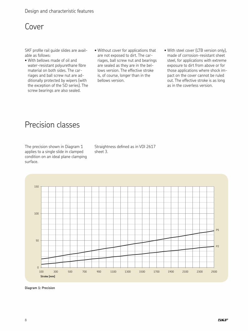
Cover
Precision classes
SKF proile rail guide slides are avail-able as follows: With bellows made of oil and • water-resistant polyurethane ibre material on both sides. The car-riages and ball screw nut are ad-ditionally protected by wipers (with the exception of the SD series). The screw bearings are also sealed.
Without cover for applications that • are not exposed to dirt. The car-riages, ball screw nut and bearings are sealed as they are in the bel-lows version. The effective stroke is, of course, longer than in the bellows version.
With steel cover (LTB version only), • made of corrosion-resistant sheet steel, for applications with extreme exposure to dirt from above or for those applications where shock im-pact on the cover cannot be ruled out. The effective stroke is as long as in the coverless version.
Diagram 1: Precision
0
50
100
150
100 300 500 700 900 1100 1300 1500 1700 1900 2100 2300 2500
Stroke [mm]
P5
P2
The precision shown in Diagram 1 applies to a single slide in clamped condition on an ideal plane clamping surface.
Straightness deined as in VDI 2617 sheet 3.

9
Design and characteristic features
StrokeThe strokes S1 (with bellows), S2 (without bellows) and S (with steel cover) given in the LTB dimen-sional tables are the maximum travel distances between the mechanical end stops. Depending on the speed and the moving mass, the operat-ing stroke must be correspondingly reduced. The overrun on both sides must be larger than the length of the brake path of the drive. The value of 2 x p (screw lead) can be considered to be a reliable guideline value. The standard pre-setting of the electrical stroke corresponds to the mechani-cal stroke minus 10 mm on both sides. This value can be individually adjusted. The maximum electrical stroke is in-dicated in the LTS dimensional table. The limit switches can be adjusted by 50 mm on each side. This will reduce the stroke accordingly.
MaterialsAs standard, the slide components are made of anodized aluminium. On request the bottom part and the top part are also available in steel.
Permissible oper-ating temperaturesSlides with ball screw drive: -20 °C to +80 °C constant tempera-tureSlides with linear motor drive: 0 °C to + 55 °C constant tempera-ture.
LubricationThe guides and slide screw are sup-plied with SKF all-purpose grease LGEP2.
The carriages and the screw nut can be relubricated. For further informa-tion please refer to the operating instructions. The slides can be itted with a central lubricating connec-tion on request. In this case, ive lube ports are provided in the side plate. (Not possible for carriages with steel cover.) Relubrication intervals depending on operating conditions: 20 - 200 km or after 1 year at the latest.
Load carrying capacity and lifeFor exact dimensioning and design of SKF proile rail guide slides and drives, please contact SKF. In order to provide the required data correctly, please ill in the speciication sheet on page 24.
AccessoriesLimit and reference switchesSlides with ball screw drive are it-ted with inductive limit switches as standard. These are integrated in the slide and connected via a central plug connection on the screw bearing plate (see dimensional tables). Induc-tive reference switches are available on request.Slides with linear motor drive are itted with 2 limit switches PNP/NC as standard.Cross table assemblyIndividual slides can be mounted to form a cross table. Please note the details in the corresponding column of the dimensional tables.
Linear encoderAs standard, slides with linear motor drive are equipped with an open lin-ear encoder on the side. For further information please refer to table 3.On request slides with ball screw drive can be also supplied with an encapsulated linear encoder. This is itted externally on the side of the slide. Motor langeSlides with ball screw drive can be equipped with a motor lange and coupling on request. When ordering please indicate the motor manufac-turer, model and type. Indirect toothed belt driveIf space is restricted, an indirect drive using a toothed belt may be the best choice. The motor can be mounted on either the right or left hand side. Standard transmission ratio 1:1. MotorsSlides with ball screw drive can be equipped with stepper motors or servo motors on request.Motor control units and control componentsThe following components are avail-able for controlling the motors:Servo module • Point-to-point or continuous path • controlFurther information available on request or in the offer as submitted.

10
Dimensional tables LTB
LTB 110.L1.SD/TN12xx-BL: Slides with ball screw drive, with or without bellows110
L112 8 52
3040
52
L3 n x 40 L3
52
50
21
11
0
Ø5
0
Ø6
h7
811.5
17
25
19
5.5 M5x10 (6x)
40
40
M4 (4x)
12
.5
11
1)
T slots in bottom part:Slot 1: for square nut DIN 562 M5Slot 2: for square nut DIN 562 M4
Length Screw data
2) Stroke3) SD1205 TN1205+1210 Weight4)
L1 L3 n KN S1 S2 nmax nmax GA GOmm - mm 1/min kg150
15
3 10 30 4 160 7 500 1,7
0,8
190 4 1 35 70 4 160 7 500 1,6230 5 60 110 4 160 7 500 1,8270 6 1 80 150 4 160 7 500 2,0310 7 105 190 4 160 7 500 2,2350 8 1 130 230 4 160 7 500 2,4390 9 155 270 4 160 7 500 2,6430 10 1 180 310 4 160 7 500 2,7470 11 205 350 4 160 7 500 2,9510 12 1 225 390 4 160 7 500 3,1550 13 250 430 4 160 6 370 3,3590 14 1 275 470 4 160 5 420 3,5630 15 300 510 4 160 4 670 3,6670 16 1 325 550 3 900 4 060 3,8710 17 350 590 3 420 3 570 4,0750 18 1 375 630 3 030 3 160 4,2790 19 395 670 2 700 2 810 4,4830 20 1 420 710 2 420 2 520 4,5870 21 445 750 2 180 2 280 4,7910 22 1 470 790 1 980 2 060 4,9950 23 495 830 1 800 1 880 5,1
2) Suitable as top axis for central cross table mounting 3) Maximum stroke between end stops: S1 with bellows (standard version) S2 without bellows (special version)4) GA = Total mass of slide GO = Linear moving mass of slide top
1) Plug connection for limit and reference switches (optional)
Direction of travel: - <———> +

11
Dimensional tables LTB
LTB 110.L1.SD/TN12xx-SC: Slides with ball screw drive and steel cover
Length Screw data
3) Stroke4) SD1205 TN1205+1210 Weight5)
L1 L3 n KN S nmax nmax GA GOmm - mm 1/min kg150
15
3 30 4 160 7 500 2,0
0,9
190 4 1 70 4 160 7 500 2,2230 5 110 4 160 7 500 2,4270 6 1 150 4 160 7 500 2,6310 7 190 4 160 7 500 2,8350 8 1 230 4 160 7 500 3,0390 9 270 4 160 7 500 3,2430 10 1 310 4 160 7 500 3,4470 11 350 4 160 7 500 3,6510 12 1 390 4 160 7 500 3,8550 13 430 4 160 6 370 4,0590 14 1 470 4 160 5 420 4,2630 15 510 4 160 4 670 4,4670 16 1 550 3 900 4 060 4,6710 17 590 3 420 3 570 4,8750 18 1 630 3 030 3 160 5,0790 19 670 2 700 2 810 5,2830 20 1 710 2 420 2 520 5,4870 21 750 2 180 2 280 5,6910 22 1 790 1 980 2 060 5,8950 23 830 1 800 1 880 6,0
110
L112 8
19
52
52
40
40
52
11
3
11
0
40 40
L3 n x 40 L3
Ø6
h7
Ø5
0
811.5
17
25
12
.5
11
50
12
2
19.7
41
21
30
47
M4 (4x)
2)M5x4 (6x)M4x9 (6x)1)
Ø5.5
T slots in bottom part:Slot 1: for square nut DIN 562 M5Slot 2: for square nut DIN 562 M4
3) Suitable as top axis for central cross table mounting 4) Maximum stroke between end stops 5) GA = Total mass of slide GO = Linear moving mass of slide top
1) Plug connection for limit and reference switches (optional) 2) Adapter plate available on request
Direction of travel: - <———> +

12
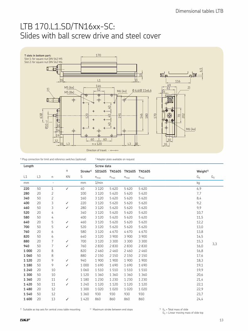
Dimensional tables LTB
Length Screw data
2) Stroke3) SD1605 TN1605 TN1605 TN1605 Weight4)
L1 L3 n KN S1 S2 nmax nmax nmax nmax GA GOmm - mm 1/min kg220 50 1 1 35 40 3 120 5 620 5 620 5 620 5,7
2,3
280 20 2 80 100 3 120 5 620 5 620 5 620 6,4340 50 2 125 160 3 120 5 620 5 620 5 620 7,1400 20 3 1 175 220 3 120 5 620 5 620 5 620 7,8460 50 3 1 220 280 3 120 5 620 5 620 5 620 8,5520 20 4 260 340 3 120 5 620 5 620 5 620 9,2580 50 4 305 400 3 120 5 620 5 620 5 620 9,9640 20 5 1 355 460 3 120 5 620 5 620 5 620 10,6700 50 5 1 400 520 3 120 5 620 5 620 5 620 11,3760 20 6 445 580 3 120 4 670 4 670 4 670 12,0820 50 6 495 640 3 120 3 900 3 900 3 900 12,7880 20 7 1 540 700 3 120 3 300 3 300 3 300 13,4940 50 7 1 580 760 2 830 2 830 2 830 2 830 14,11 000 20 8 625 820 2 460 2 460 2 460 2 460 14,81 060 50 8 675 880 2 150 2 150 2 150 2 150 15,61 120 20 9 1 720 940 1 900 1 900 1 900 1 900 16,31 180 50 9 1 765 1 000 1 690 1 690 1 690 1 690 17,01 240 20 10 815 1 060 1 510 1 510 1 510 1 510 17,71 300 50 10 860 1 120 1 360 1 360 1 360 1 360 18,41 360 20 11 1 900 1 180 1 230 1 230 1 230 1 230 19,11 420 50 11 1 945 1 240 1 120 1 120 1 120 1 120 19,81 480 20 12 995 1 300 1 020 1 020 1 020 1 020 20,51 540 50 12 1 040 1 360 930 930 930 930 21,21 600 20 13 1 1 085 1 420 860 860 860 860 21,9
LTB 170.L1.SD/TN16xx-BL: Slides with ball screw drive, with or without bellows170
15 L1 10
15
116
6.5
52
1461
20
40
40
40
14
6
L3 n x 120 L3
10
14
19
32
M6 (4x)M5 (8x)1)
60
70
17
0
30
35
M6 (4x)
Ø1
0 h
7
Ø6
3
Ø 6,6/Ø 11x6,6
T slots in bottom part:Slot 1: for square nut DIN 562 M5Slot 2: for square nut DIN 562 M4
2) Suitable as top axis for central cross table mounting 3) Maximum stroke between end stops: S1 with bellows (standard version) S2 without bellows (special version)4) GA = Total mass of slide GO = Linear moving mass of slide top
1) Plug connection for limit and reference switches (optional)
Direction of travel: - <———> +
13
Dimensional tables LTB
LTB 170.L1.SD/TN16xx-SC: Slides with ball screw drive and steel cover170
15 L1 10
15
116
6.5
52146
60 60
15 L3 n x 120 L3 10
10
14
19
32
Ø1
0 h
7
63
Ø
1)
14
6
18
0
M6 (4x)M5 (8x)
M5 (6x)1
20
40
40
40
Ø 6,6/Ø 11x6,6
17
0
70
20
2
30
35
166169
2)
M6 (4x)
19
1
T slots in bottom part:Slot 1: for square nut DIN 562 M5Slot 2: for square nut DIN 562 M4
3) Suitable as top axis for central cross table mounting 4) Maximum stroke between end stops 5) GA = Total mass of slide GO = Linear moving mass of slide top
1) Plug connection for limit and reference switches (optional) 2) Adapter plate available on requestLength Screw data
3) Stroke4) SD1605 TN1605 TN1605 TN1605 Weight5)
L1 L3 n KN S nmax nmax nmax nmax GA GOmm - mm 1/min kg220 50 1 1 40 3 120 5 620 5 620 5 620 6,9
3,3
280 20 2 100 3 120 5 620 5 620 5 620 7,7340 50 2 160 3 120 5 620 5 620 5 620 8,4400 20 3 1 220 3 120 5 620 5 620 5 620 9,2460 50 3 1 280 3 120 5 620 5 620 5 620 9,9520 20 4 340 3 120 5 620 5 620 5 620 10,7580 50 4 400 3 120 5 620 5 620 5 620 11,5640 20 5 1 460 3 120 5 620 5 620 5 620 12,2700 50 5 1 520 3 120 5 620 5 620 5 620 13,0760 20 6 580 3 120 4 670 4 670 4 670 13,8820 50 6 640 3 120 3 900 3 900 3 900 14,5880 20 7 1 700 3 120 3 300 3 300 3 300 15,3940 50 7 1 760 2 830 2 830 2 830 2 830 16,01 000 20 8 820 2 460 2 460 2 460 2 460 16,81 060 50 8 880 2 150 2 150 2 150 2 150 17,61 120 20 9 1 940 1 900 1 900 1 900 1 900 18,31 180 50 9 1 1 000 1 690 1 690 1 690 1 690 19,11 240 20 10 1 060 1 510 1 510 1 510 1 510 19,91 300 50 10 1 120 1 360 1 360 1 360 1 360 20,61 360 20 11 1 1 180 1 230 1 230 1 230 1 230 21,41 420 50 11 1 1 240 1 120 1 120 1 120 1 120 22,11 480 20 12 1 300 1 020 1 020 1 020 1 020 22,91 540 50 12 1 360 930 930 930 930 23,71 600 20 13 1 1 420 860 860 860 860 24,4
Direction of travel: - <———> +
14
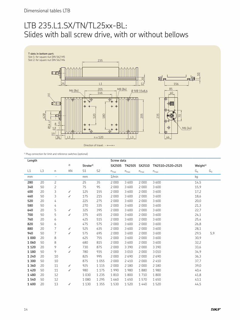
Dimensional tables LTB
LTB 235.L1.SX/TN/TL25xx-BL: Slides with ball screw drive, with or without bellows235
25 L1 12
20
156
10
20
5
L3 n x 120 L3
8
12
1936
Ø1
4 h
7
62
Ø
1)Ø 9/Ø 15x8,6
40
85
46
23
5
70
M6 (4x)
146205M6 (8x) M8 (8x)
12
0
18
0
T slots in bottom part:Slot 1: for square nut DIN 562 M5Slot 2: for square nut DIN 562 M4
Length Screw data
2) Stroke3) SX2505 TN2505 SX2510 TN2510+2520+2525 Weight4)
L1 L3 n KN S1 S2 nmax nmax nmax nmax GA GOmm - mm 1/min kg280 20 2 25 35 2 000 3 600 2 000 3 600 14,5
5,9
340 50 2 75 95 2 000 3 600 2 000 3 600 15,9400 20 3 1 125 155 2 000 3 600 2 000 3 600 17,2460 50 3 1 175 215 2 000 3 600 2 000 3 600 18,6520 20 4 225 275 2 000 3 600 2 000 3 600 20,0580 50 4 270 335 2 000 3 600 2 000 3 600 21,3640 20 5 1 325 395 2 000 3 600 2 000 3 600 22,7700 50 5 1 375 455 2 000 3 600 2 000 3 600 24,1760 20 6 425 515 2 000 3 600 2 000 3 600 25,4820 50 6 475 575 2 000 3 600 2 000 3 600 26,8880 20 7 1 525 635 2 000 3 600 2 000 3 600 28,1940 50 7 1 575 695 2 000 3 600 2 000 3 600 29,51 000 20 8 625 755 2 000 3 600 2 000 3 600 30,91 060 50 8 680 815 2 000 3 600 2 000 3 600 32,21 120 20 9 1 730 875 2 000 3 390 2 000 3 390 33,61 180 50 9 1 780 935 2 000 3 010 2 000 3 010 34,91 240 20 10 825 995 2 000 2 690 2 000 2 690 36,31 300 50 10 875 1 055 2 000 2 410 2 000 2 410 37,71 360 20 11 1 925 1 115 2 000 2 180 2 000 2 180 39,01 420 50 11 1 980 1 175 1 990 1 980 1 880 1 980 40,41 480 20 12 1 030 1 235 1 810 1 800 1 710 1 800 41,81 540 50 12 1 080 1 295 1 660 1 650 1 570 1 650 43,11 600 20 13 1 1 130 1 355 1 530 1 520 1 440 1 520 44,5
1) Plug connection for limit and reference switches (optional)
Direction of travel: - <———> +
15
Dimensional tables LTB
Length Screw data
2) Stroke3) SX2505 TN2505 SX2510 TN2510+2520+2525 Weight4)
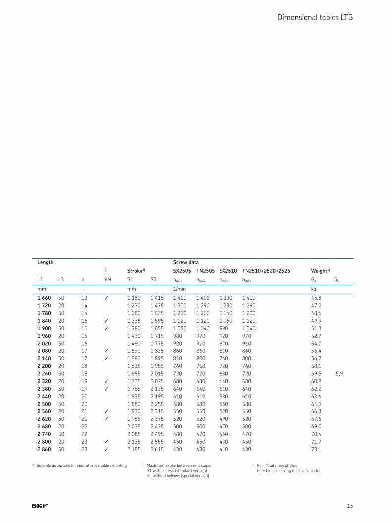
L1 L3 n KN S1 S2 nmax nmax nmax nmax GA GOmm - mm 1/min kg1 660 50 13 1 1 180 1 415 1 410 1 400 1 330 1 400 45,8
5,9
1 720 20 14 1 230 1 475 1 300 1 290 1 230 1 290 47,21 780 50 14 1 280 1 535 1 210 1 200 1 140 1 200 48,61 840 20 15 1 1 335 1 595 1 120 1 120 1 060 1 120 49,91 900 50 15 1 1 380 1 655 1 050 1 040 990 1 040 51,31 960 20 16 1 430 1 715 980 970 920 970 52,72 020 50 16 1 480 1 775 920 910 870 910 54,02 080 20 17 1 1 530 1 835 860 860 810 860 55,42 140 50 17 1 1 580 1 895 810 800 760 800 56,72 200 20 18 1 635 1 955 760 760 720 760 58,12 260 50 18 1 685 2 015 720 720 680 720 59,52 320 20 19 1 1 735 2 075 680 680 640 680 60,82 380 50 19 1 1 785 2 135 640 640 610 640 62,22 440 20 20 1 835 2 195 610 610 580 610 63,62 500 50 20 1 880 2 255 580 580 550 580 64,92 560 20 21 1 1 930 2 315 550 550 520 550 66,32 620 50 21 1 1 985 2 375 520 520 490 520 67,62 680 20 22 2 035 2 435 500 500 470 500 69,02 740 50 22 2 085 2 495 480 470 450 470 70,42 800 20 23 1 2 135 2 555 450 450 430 450 71,72 860 50 23 1 2 185 2 615 430 430 410 430 73,1
2) Suitable as top axis for central cross table mounting 3) Maximum stroke between end stops: S1 with bellows (standard version) S2 without bellows (special version)4) GA = Total mass of slide GO = Linear moving mass of slide top

16
Dimensional tables LTB
LTB 235.L1.SX/TN/TL25xx-SC: Slides with ball screw drive and steel cover235
25 L1 12
20
156
10
75.5 75.5
25 L3 n x 120 L3 12
12
0
20
5
8
12
19
36
Ø1
4 h
7
62
Ø
1) Ø 9/Ø 15x8,6
M6 (6x)
26
2
23
5
21
87
97
40
46
70
27
5
M6 (4x)
2)
24
8
18
0
146205
M6 (8x) M8 (8x)
T slots in bottom part:Slot 1: for square nut DIN 562 M5Slot 2: for square nut DIN 562 M4
Length Screw data
3) Stroke4) SX2505 TN2505 SX2510 TN2510+2520+2525 Weight5)
L1 L3 n KN S nmax nmax nmax nmax GA GOmm - mm 1/min kg280 20 2 35 2 000 3 600 2 000 3 600 18,1
8,5
340 50 2 95 2 000 3 600 2 000 3 600 19,6400 20 3 1 155 2 000 3 600 2 000 3 600 21,1460 50 3 1 215 2 000 3 600 2 000 3 600 22,7520 20 4 275 2 000 3 600 2 000 3 600 24,2580 50 4 335 2 000 3 600 2 000 3 600 25,7640 20 5 1 395 2 000 3 600 2 000 3 600 27,3700 50 5 1 455 2 000 3 600 2 000 3 600 28,8760 20 6 515 2 000 3 600 2 000 3 600 30,3820 50 6 575 2 000 3 600 2 000 3 600 31,8880 20 7 1 635 2 000 3 600 2 000 3 600 33,4940 50 7 1 695 2 000 3 600 2 000 3 600 34,91 000 20 8 755 2 000 3 600 2 000 3 600 36,41 060 50 8 815 2 000 3 600 2 000 3 600 37,91 120 20 9 1 875 2 000 3 390 2 000 3 390 39,51 180 50 9 1 935 2 000 3 010 2 000 3 010 41,01 240 20 10 995 2 000 2 690 2 000 2 690 42,51 300 50 10 1 055 2 000 2 410 2 000 2 410 44,11 360 20 11 1 1 115 2 000 2 180 2 000 2 180 45,61 420 50 11 1 1 175 1 990 1 980 1 880 1 980 47,11 480 20 12 1 235 1 810 1 800 1 710 1 800 48,61 540 50 12 1 295 1 660 1 650 1 570 1 650 50,21 600 20 13 1 1 355 1 530 1 520 1 440 1 520 51,7
1) Plug connection for limit and reference switches (optional) 2) Adapter plate available on request
Direction of travel: - <———> +
17
Dimensional tables LTB
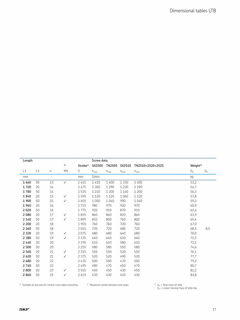
3) Suitable as top axis for central cross table mounting 4) Maximum stroke between end stops 5) GA = Total mass of slide GO = Linear moving mass of slide top
Length Screw data
3) Stroke4) SX2505 TN2505 SX2510 TN2510+2520+2525 Weight5)
L1 L3 n KN S nmax nmax nmax nmax GA GOmm - mm 1/min kg1 660 50 13 1 1 415 1 410 1 400 1 330 1 400 53,2
8,5
1 720 20 14 1 475 1 300 1 290 1 230 1 290 54,71 780 50 14 1 535 1 210 1 200 1 140 1 200 56,31 840 20 15 1 1 595 1 120 1 120 1 060 1 120 57,81 900 50 15 1 1 655 1 050 1 040 990 1 040 59,31 960 20 16 1 715 980 970 920 970 60,92 020 50 16 1 775 920 910 870 910 62,42 080 20 17 1 1 835 860 860 810 860 63,92 140 50 17 1 1 895 810 800 760 800 65,42 200 20 18 1 955 760 760 720 760 67,02 260 50 18 2 015 720 720 680 720 68,52 320 20 19 1 2 075 680 680 640 680 70,02 380 50 19 1 2 135 640 640 610 640 71,52 440 20 20 2 195 610 610 580 610 73,12 500 50 20 2 255 580 580 550 580 74,62 560 20 21 1 2 315 550 550 520 550 76,12 620 50 21 1 2 375 520 520 490 520 77,72 680 20 22 2 435 500 500 470 500 79,22 740 50 22 2 495 480 470 450 470 80,72 800 20 23 1 2 555 450 450 430 450 82,22 860 50 23 1 2 615 430 430 410 430 83,8

18
Dimensional tables LTB
LTB 320.L1.SX/TN/TL32xx-BL: Slides with ball screw drive, with or without bellows350
35 L1 25
40
205280
L3 n x 120 L3
28
0
4 x
60
915
22
44
Ø2
0 h
7
Ø7
5
1)
M8 (10x) M10 (10x)
32
0
90
50
115
57
M8 (4x)
Ø 11/Ø 18x10,6
Length Screw data
Stroke2) SX3205 TN3205 SX3210 TN3210 TN3220+3232+3240 Weight3)
L1 L3 n S1 S2 nmax nmax nmax nmax nmax GA GOmm - mm 1/min kg580
50
4 185 220 1 560 2 810 1 560 2 810 2 810 43,5
13,3
700 5 290 340 1 560 2 810 1 560 2 810 2 810 48,5820 6 390 460 1 560 2 810 1 560 2 810 2 810 53,4940 7 500 580 1 560 2 810 1 560 2 810 2 810 58,41 060 8 600 700 1 560 2 810 1 560 2 810 2 810 63,31 180 9 710 820 1 560 2 810 1 560 2 810 2 810 68,21 300 10 810 940 1 560 2 810 1 560 2 810 2 810 73,21 420 11 915 1 060 1 560 2 810 1 560 2 810 2 810 78,11 540 12 1 015 1 180 1 560 2 610 1 560 2 520 2 520 83,11 660 13 1 125 1 300 1 560 2 180 1 560 2 100 2 100 88,01 780 14 1 225 1 420 1 560 1 850 1 560 1 780 1 780 92,91 900 15 1 335 1 540 1 560 1 590 1 440 1 530 1 530 97,92 020 16 1 435 1 660 1 380 1 380 1 250 1 330 1 330 102,82 140 17 1 540 1 780 1 210 1 200 1 090 1 160 1 160 107,82 260 18 1 645 1 900 1 070 1 060 970 1 030 1 030 112,72 380 19 1 750 2 020 950 950 860 910 910 117,72 500 20 1 850 2 140 850 850 770 820 820 122,62 620 21 1 960 2 260 760 760 690 740 740 127,52 740 22 2 060 2 380 690 690 630 670 670 132,52 860 23 2 165 2 500 630 630 570 600 600 137,4
2) Maximum stroke between end stops S1 with bellows (standard version) S2 without bellows (special version)5) GA = Total mass of slide GO = Linear moving mass of slide top
1) Plug connection for limit and reference switches (optional)
Direction of travel: - <———> +

19
Dimensional tables LTB
LTB 320.L1.SX/TN/TL32xx-SC: Slides with ball screw drive and steel cover350
35 L1 25
40
205280
4 x
60
34
8
28
0
3 x 8735 L3 n x 120 L3 25
9
15
22
44
Ø2
0 h
7
Ø7
5
1)
M8 (10x) M10 (10x) Ø 11/Ø 18x10,6
M8
32
0
90
36
5
40
57
118
50
138
M8 (4x)
2)
Length Screw data
Stroke3) SX3205 TN3205 SX3210 TN3210 TN3220+3232+3240 Weight4)
L1 L3 n S nmax nmax nmax nmax nmax GA GOmm - mm 1/min kg580
50
4 220 1 560 2 810 1 560 2 810 2 810 62,9
30,4
700 5 340 1 560 2 810 1 560 2 810 2 810 68,3820 6 460 1 560 2 810 1 560 2 810 2 810 73,8940 7 580 1 560 2 810 1 560 2 810 2 810 79,21 060 8 700 1 560 2 810 1 560 2 810 2 810 84,61 180 9 820 1 560 2 810 1 560 2 810 2 810 90,01 300 10 940 1 560 2 810 1 560 2 810 2 810 95,51 420 11 1 060 1 560 2 810 1 560 2 810 2 810 100,91 540 12 1 180 1 560 2 610 1 560 2 520 2 520 106,31 660 13 1 300 1 560 2 180 1 560 2 100 2 100 111,71 780 14 1 420 1 560 1 850 1 560 1 780 1 780 117,21 900 15 1 540 1 560 1 590 1 440 1 530 1 530 122,62 020 16 1 660 1 380 1 380 1 250 1 330 1 330 128,02 140 17 1 780 1 210 1 200 1 090 1 160 1 160 133,52 260 18 1 900 1 070 1 060 970 1 030 1 030 138,92 380 19 2 020 950 950 860 910 910 144,32 500 20 2 140 850 850 770 820 820 149,72 620 21 2 260 760 760 690 740 740 155,22 740 22 2 380 690 690 630 670 670 160,62 860 23 2 500 630 630 570 600 600 166,0
3) Maximum stroke between end stops 4) GA = Total mass of slide GO = Linear moving mass of slide top
1) Plug connection for limit and reference switches (optional) 2) Adapter plate available on request
Direction of travel: - <———> +
20
Dimensional tables LTB
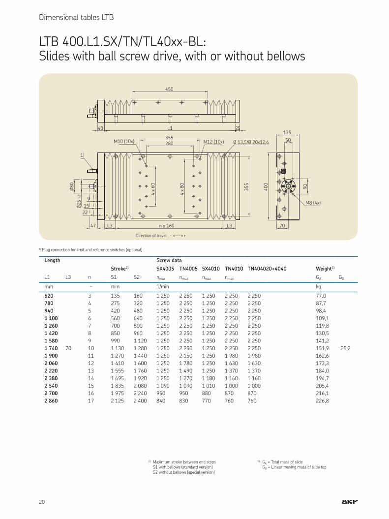
LTB 400.L1.SX/TN/TL40xx-BL: Slides with ball screw drive, with or without bellows
Length Screw data
Stroke2) SX4005 TN4005 SX4010 TN4010 TN404020+4040 Weight3)
L1 L3 n S1 S2 nmax nmax nmax nmax GA GOmm - mm 1/min kg620
70
3 135 160 1 250 2 250 1 250 2 250 2 250 77,0
25,2
780 4 275 320 1 250 2 250 1 250 2 250 2 250 87,7940 5 420 480 1 250 2 250 1 250 2 250 2 250 98,41 100 6 560 640 1 250 2 250 1 250 2 250 2 250 109,11 260 7 700 800 1 250 2 250 1 250 2 250 2 250 119,81 420 8 850 960 1 250 2 250 1 250 2 250 2 250 130,51 580 9 990 1 120 1 250 2 250 1 250 2 250 2 250 141,21 740 10 1 130 1 280 1 250 2 250 1 250 2 250 2 250 151,91 900 11 1 270 1 440 1 250 2 150 1 250 1 980 1 980 162,62 060 12 1 410 1 600 1 250 1 780 1 250 1 630 1 630 173,32 220 13 1 555 1 760 1 250 1 490 1 250 1 370 1 370 184,02 380 14 1 695 1 920 1 250 1 270 1 180 1 160 1 160 194,72 540 15 1 835 2 080 1 090 1 090 1 010 1 000 1 000 205,42 700 16 1 975 2 240 950 950 880 870 870 216,12 860 17 2 125 2 400 840 830 770 760 760 226,8
2) Maximum stroke between end stops S1 with bellows (standard version) S2 without bellows (special version)5) GA = Total mass of slide GO = Linear moving mass of slide top
450
40 L1 25
280355
4 x
60
4 x
80
L3 n x 160 L3
35
5
9
15
22
47
Ø2
5 h
7
Ø8
0
1)
M10 (10x) M12 (10x) Ø 13,5/Ø 20x12,6
90
40
0
70
50
135
M8 (4x)
1) Plug connection for limit and reference switches (optional)
Direction of travel: - <———> +

21
Dimensional tables LTS
LTS 154.L1.1FN3-050-xK: Slides with linear motor drive, with or without bellows L2L6
L1 10
L56
06
0
80
ca. 100
n x 120 80
12
7
15
4
15
44
1
30
81M6x10 (6x)
Ø 6,6/Ø 11x6,6
ca.14
LTS 154.L1.1FN3-050-1K LTS 154.L1.1FN3-050-2K
2) Stroke1) 3) Stroke1) 3)
L1 n GU L2 L5 L6 S1 S2 GO L2 L5 S1 S2 GOmm - kg mm kg mm kg280 1 4,5
142 118 22,5
77 98
2,7 247 127
- -
4,6
400 2 6,2 166 218 86 113
520 3 7,9 256 338 175 233
640 4 9,5 345 458 264 353
760 5 11,2 434 578 354 473
880 6 12,8 524 698 443 593
1 000 7 14,5 613 818 533 713
1 120 8 16,1 703 938 622 833
1 240 9 17,8 792 1 058 711 935
1 360 10 19,4 881 1 178 801 1 0731 480 11 21,0 971 1 298 890 1 1931 600 12 22,6 1 060 1 418 980 1 3131 720 13 24,3 1 150 1 538 1 075 1 4331 840 14 25,9 1 239 1 658 1 165 1 5531 960 15 27,5 1 328 1 778 1 254 1 673
1) Operating stroke 2) GU = Stationary mass of slide bottom S1 with bellows 3) GO = Linear moving mass of slide top S2 without bellows
The operating stroke is deined as the maximum stroke between the limit switches.Distance limit switch – end plate 20 mm (LTS without bellows)Distance limit switch – end buffer 7,5 mm (LTS without bellows)Distance limit switch – block length bellows 10 mm (LTS with bellows)
Direction of travel: + <———> -

22
Dimensional tables LTS
LTS 182.L1.1FN3-100-xK: Slides with linear motor drive, with or without bellows L2 ca. 14
L110 10
60
60
L5
L7
80
ca. 100
n x 120 80
15
5
18
2
18
24
1
81
30
M6x10 (6x)
M6x10 (6x)
Ø 6,6/Ø 11x6,6
L6
Length LTS 182.L1.1FN3-100-1K LTS 182.L1.1FN3-100-2K LTS 182.L1 .1FN3-100-3K
2) Stroke1) 3) Stroke1) 3) Stroke1) 3)
L1 n GU L2 L5 L6 S1 S2 GO L2 L5 L7 S1 S2 GO L2 L5 L7 S1 S2 GOmm - kg mm kg mm kg mm kg280 1 5,5
142 118 22,5
77 98
3,7 247 127 155
- -
6,1 352 127 155
- -
8,6
400 2 7,6 166 218 86 113 - -520 3 9,7 256 338 175 233 101 128
640 4 11,8 345 458 264 353 190 248
760 5 13,8 434 578 354 473 279 368
880 6 15,9 524 698 443 593 369 488
1 000 7 17,9 613 818 533 713 458 608
1 120 8 20,0 703 938 622 833 548 728
1 240 9 22,0 792 1 058 711 935 637 848
1 360 10 24,1 881 1 178 801 1 073 726 968
1 480 11 26,1 971 1 298 890 1 193 816 1 0881 600 12 28,2 1 060 1 418 980 1 313 905 1 2081 720 13 30,2 1 150 1 538 1 075 1 433 995 1 3281 840 14 32,2 1 239 1 658 1 165 1 553 1 084 1 4481 960 15 34,3 1 328 1 778 1 254 1 673 1 173 1 568
1) Operating stroke 2) GU = Stationary mass of slide bottom S1 with bellows 3) GO = Linear moving mass of slide top S2 without bellows
The operating stroke is deined as the maximum stroke between the limit switches.Distance limit switch – end plate 20 mm (LTS without bellows)Distance limit switch – end buffer 7,5 mm (LTS without bellows)Distance limit switch – block length bellows 10 mm (LTS with bellows)
Direction of travel: + <———> -
23
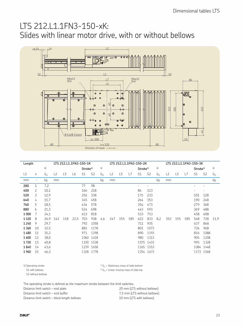
Dimensional tables LTS
LTS 212.L1.1FN3-150-xK: Slides with linear motor drive, with or without bellows L2 ca.14
L110 10
L5
L7
80 n x 120 80
ca. 100
18
5
21
2
21
24
1
32
86M6x12 (6x)
M6x12 (6x)
Ø 6,6/Ø 11x6,6
60
60
L6
Length LTS 212.L1.1FN3-150-1K LTS 212.L1.1FN3-150-2K LTS 212.L1.1FN3-150-3K
2) Stroke1) 3) Stroke1) 3) Stroke1) 3)
L1 n GU L2 L5 L6 S1 S2 GO L2 L5 L7 S1 S2 GO L2 L5 L7 S1 S2 GOmm - kg mm kg mm kg mm kg280 1 7,2
142 118 22,5
77 98
4,6 247 155 185
- -
8,2 352 155 185
- -
11,9
400 2 10,1 166 218 86 113 - -520 3 12,9 256 338 175 233 101 128
640 4 15,7 345 458 264 353 190 248
760 5 18,5 434 578 354 473 279 368
880 6 21,3 524 698 443 593 369 488
1 000 7 24,1 613 818 533 713 458 608
1 120 8 26,9 703 938 622 833 548 728
1 240 9 29,7 792 1 058 711 935 637 848
1 360 10 32,5 881 1 178 801 1 073 726 968
1 480 11 35,2 971 1 298 890 1 193 816 1 0881 600 12 38,0 1 060 1 418 980 1 313 905 1 2081 720 13 40,8 1 150 1 538 1 075 1 433 995 1 3281 840 14 43,6 1 239 1 658 1 165 1 553 1 084 1 4481 960 15 46,3 1 328 1 778 1 254 1 673 1 173 1 568
1) Operating stroke 2) GU = Stationary mass of slide bottom S1 with bellows 3) GO = Linear moving mass of slide top S2 without bellows
The operating stroke is deined as the maximum stroke between the limit switches.Distance limit switch – end plate 20 mm (LTS without bellows)Distance limit switch – end buffer 7,5 mm (LTS without bellows)Distance limit switch – block length bellows 10 mm (LTS with bellows)
Direction of travel: + <———> -

24
Speciication sheet
Speciication sheet for the selection of proile rail guide slides1. Customer
Company . . . . . . . . . . . . . . . . . . . . . . . . . . . . . . .
Name . . . . . . . . . . . . . . . . . . . . . . . . . . . . . . . Job title Name . . . . . . . . . . . . . . . . . . . . . . . . . . . . . . . Job title Name . . . . . . . . . . . . . . . . . . . . . . . . . . . . . . . Job title
Street Post code City Country Phone Fax Email
2. Application . . . . . . . . . . . . . . . . . . . . . . . . . . . . . . . . . . . . . . . . . . . . . . . . . . . . . . . . . . . . . . . . . . . . . . . . . . . . . . . . . . . . . . . . . . . . . . . . . . . . . . . . . . . . . . . . . . . . . . . . . . . . . . . . . . . . . . . . . . . . . . . . . . . . . . . . . . . . . . . . . . . . . . . . . . . . . . . . . . . . . . . . . . . . . . . . . . . . . . . . . . . . . . . . . . . . . . . . . . . . . . . . . . . . . . . . . .Description . . . . . . . . . . . . . . . . . . . . . . . . . . . . . . . . . . . . . . . . . . . . . . . . . . . . . . . . . . . . . . . . . . . . . . . . . . . . . . . . . . . . . . . . . . . . . . . . . . . . . . . . . . . . . . . . . . . . . . . . . . . . . . . . . . . . . . . . . . . . . . . . . . . . . . . . . . . . . . . . . . . . . . . . . . . . . . . . . . . . . . . . . . . . . . . . . . . . . . . . . . . . . . . . . . . . . . . . . . . . . . . . . . . . . . . . . . . . . . . . . . . . . . . . . . . . . . . . . . . . . . . . . . . . . . . . . . . . . . . . . . . . . . . . . . . . . . . . . . . . . . . . . . . . . . . . . . . . . . . . . . . . . . . . . . . . . . . . . . . . . . . . . . . . . . . . . . . . . . . . . . . . . . . . . . . . . . . . . . . . . . . . . . . . . . . . . . . . . . . . . . . . . . . . . . . . . . . . . . . . . . . . . . . . . . . . . . . . . . . . . . . . . . . . . . . . . . . . . . . . . . . . . . . . . . . . . . . . . . . . . . . . . . . . . . . . . . . . . . . . . . . . . . . . . . . . . . . . . . . . . . . . . . . . . . . . . . . . . . . . . . . . . . . . . . . . . . . . . . . . . . . . Implied demand . . . . . . . . . . . . . . . . . . . . . . . . . . . . . . . . . . . . . . . . . . . . . . . . . . . . . . . . . . . . . . . . . . . . . . . . . . . . . . . . . . . . . . . . . . . . . . . . . . . . . . . . . . . . . . . . . . . . . . . . . . . . . . . . . . . . . . . . . . . . . . . . . . . . . . . . . . . . . . . . . . . . . . . . . . . . . . . . . . . . . . . . . . . . . . . . . . . . . . . . . . . . . . . . . . . . . . . . . . . . . . . . . . . . . . . . . . . . . . . . . . . . . . . . . . . . . . . . . . . . . . . . . . . . . . . . . . . . . . . . . . . . . . . . . . . . . . . . . . . . . . . . . . . . . . . . . . . . . . . . . . . . . . . . . . . . . . . . . . . . . . . . . . . . . . . . . . . . . . . . . . . . . . . . . . . . . . . . . . . . . . . . . . . . . . . . . . . . . . . . . . . . . . . . . . . . . . . . . . . . . . . . . . . . . . . . . . . . . . . . . . . . . . . . . . . . . . . . . . . . . . . . . . . . . . . . . . . . . . . . . . . . . . . . . . . . . . . . . . . . . . . . . . . . . . . . . . . . . . . . . . . . . . . . . . . . . . . . . . . . . . . . . . . . . . . . . . . . . . . . . . . .
25
Speciication sheet
X Y Z
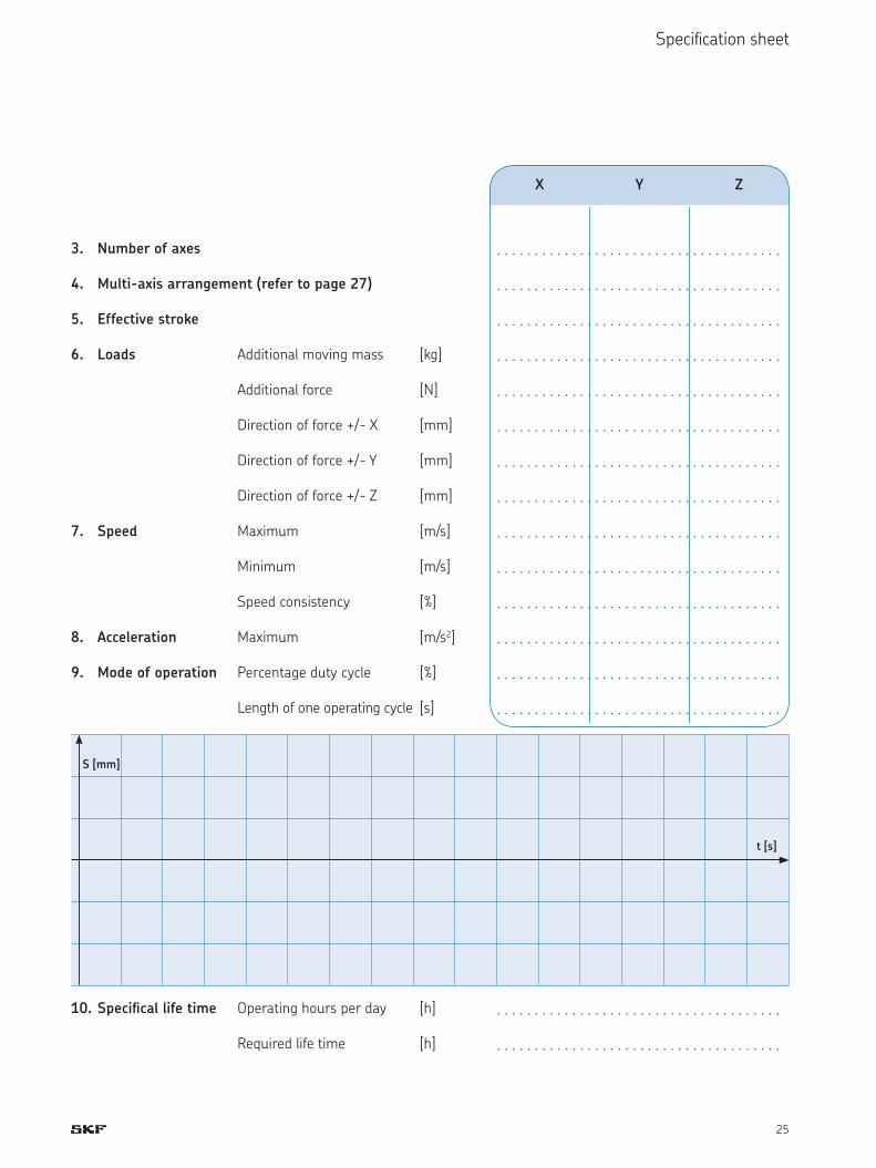
3. Number of axes . . . . . . . . . . . . . . . . . . . . . . . . . . . . . . . . . . . . . .4. Multi-axis arrangement (refer to page 27) . . . . . . . . . . . . . . . . . . . . . . . . . . . . . . . . . . . . . .5. Effective stroke . . . . . . . . . . . . . . . . . . . . . . . . . . . . . . . . . . . . . .6. Loads Additional moving mass [kg] . . . . . . . . . . . . . . . . . . . . . . . . . . . . . . . . . . . . . . Additional force [N] . . . . . . . . . . . . . . . . . . . . . . . . . . . . . . . . . . . . . . Direction of force +/- X [mm] . . . . . . . . . . . . . . . . . . . . . . . . . . . . . . . . . . . . . . Direction of force +/- Y [mm] . . . . . . . . . . . . . . . . . . . . . . . . . . . . . . . . . . . . . . Direction of force +/- Z [mm] . . . . . . . . . . . . . . . . . . . . . . . . . . . . . . . . . . . . . .7. Speed Maximum [m/s] . . . . . . . . . . . . . . . . . . . . . . . . . . . . . . . . . . . . . . Minimum [m/s] . . . . . . . . . . . . . . . . . . . . . . . . . . . . . . . . . . . . . . Speed consistency [%] . . . . . . . . . . . . . . . . . . . . . . . . . . . . . . . . . . . . . .8. Acceleration Maximum [m/s2] . . . . . . . . . . . . . . . . . . . . . . . . . . . . . . . . . . . . . .9. Mode of operation Percentage duty cycle [%] . . . . . . . . . . . . . . . . . . . . . . . . . . . . . . . . . . . . . . Length of one operating cycle [s] . . . . . . . . . . . . . . . . . . . . . . . . . . . . . . . . . . . . . .
10. Speciical life time Operating hours per day [h] . . . . . . . . . . . . . . . . . . . . . . . . . . . . . . . . . . . . . . Required life time [h] . . . . . . . . . . . . . . . . . . . . . . . . . . . . . . . . . . . . . .
S [mm]
t [s]
26
Speciication sheet
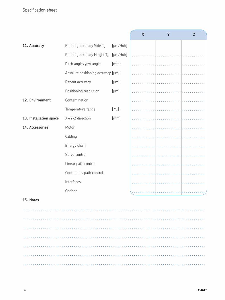
11. Accuracy Running accuracy Side Ty [µm/Hub] . . . . . . . . . . . . . . . . . . . . . . . . . . . . . . . . . . . . . . Running accuracy Height Tz [µm/Hub] . . . . . . . . . . . . . . . . . . . . . . . . . . . . . . . . . . . . . . Pitch angle / yaw angle [mrad] . . . . . . . . . . . . . . . . . . . . . . . . . . . . . . . . . . . . . . Absolute positioning accuracy [µm] . . . . . . . . . . . . . . . . . . . . . . . . . . . . . . . . . . . . . . Repeat accuracy [µm] . . . . . . . . . . . . . . . . . . . . . . . . . . . . . . . . . . . . . . Positioning resolution [µm] . . . . . . . . . . . . . . . . . . . . . . . . . . . . . . . . . . . . . .12. Environment Contamination . . . . . . . . . . . . . . . . . . . . . . . . . . . . . . . . . . . . . . Temperature range [ °C] . . . . . . . . . . . . . . . . . . . . . . . . . . . . . . . . . . . . . .13. Installation space X-/Y-Z direction [mm] . . . . . . . . . . . . . . . . . . . . . . . . . . . . . . . . . . . . . .14. Accessories Motor . . . . . . . . . . . . . . . . . . . . . . . . . . . . . . . . . . . . . . Cabling . . . . . . . . . . . . . . . . . . . . . . . . . . . . . . . . . . . . . . Energy chain . . . . . . . . . . . . . . . . . . . . . . . . . . . . . . . . . . . . . . Servo control . . . . . . . . . . . . . . . . . . . . . . . . . . . . . . . . . . . . . . Linear path control . . . . . . . . . . . . . . . . . . . . . . . . . . . . . . . . . . . . . . Continuous path control . . . . . . . . . . . . . . . . . . . . . . . . . . . . . . . . . . . . . . Interfaces . . . . . . . . . . . . . . . . . . . . . . . . . . . . . . . . . . . . . . Options . . . . . . . . . . . . . . . . . . . . . . . . . . . . . . . . . . . . . .15. Notes
. . . . . . . . . . . . . . . . . . . . . . . . . . . . . . . . . . . . . . . . . . . . . . . . . . . . . . . . . . . . . . . . . . . . . . . . . . . . . . . . . . . . . . . . . . . . . . . . . . . . . . . . . . . . . . . . . . . . . . . . . . . . . . . . . . . . . . . . . . . . . . . . . . . . . . . . . . . . . . . . . . . . . . . . . . . . . . . . . . . . . . . . . . . . . . . . . . . . . . . . . . . . . . . . . . . . . . . . . . . . . . . . . . . . . . . . . . . . . . . . . . . . . . . . . . . . . . . . . . . . . . . . . . . . . . . . . . . . . . . . . . . . . . . . . . . . . . . . . . . . . . . . . . . . . . . . . . . . . . . . . . . . . . . . . . . . . . . . . . . . . . . . . . . . . . . . . . . . . . . . . . . . . . . . . . . . . . . . . . . . . . . . . . . . . . . . . . . . . . . . . . . . . . . . . . . . . . . . . . . . . . . . . . . . . . . . . . . . . . . . . . . . . . . . . . . . . . . . . . . . . . . . . . . . . . . . . . . . . . . . . . . . . . . . . . . . . . . . . . . . . . . . . . . . . . . . . . . . . . . . . . . . . . . . . . . . . . . . . . . . . . . . . . . . . . . . . . . . . . . . . . . . . . . . . . . . . . . . . . . . . . . . . . . . . . . . . . . . . . . . . . . . . . . . . . . . . . . . . . . . . . . . . . . . . . . . . . . . . . . . . . . . . . . . . . . . . . . . . .
X Y Z

27
Speciication sheet
Examples of possible axes conigurations
X
Y
Z
X1
YX2
Y
X
X
Y
Z
X1
Y1
X2
Y2
X
Y
Bild 5: Single axis X + cross table Y/Z
Bild 3: H-Gantry X1/X2 + Y
Bild 1: Cross table X/Y
Bild 6: Cross table X/Y + single axis Z
Bild 4: H-Gantry X1/X2 + Y1/Y2
Bild 2: Gantry X/Y
28
Order code
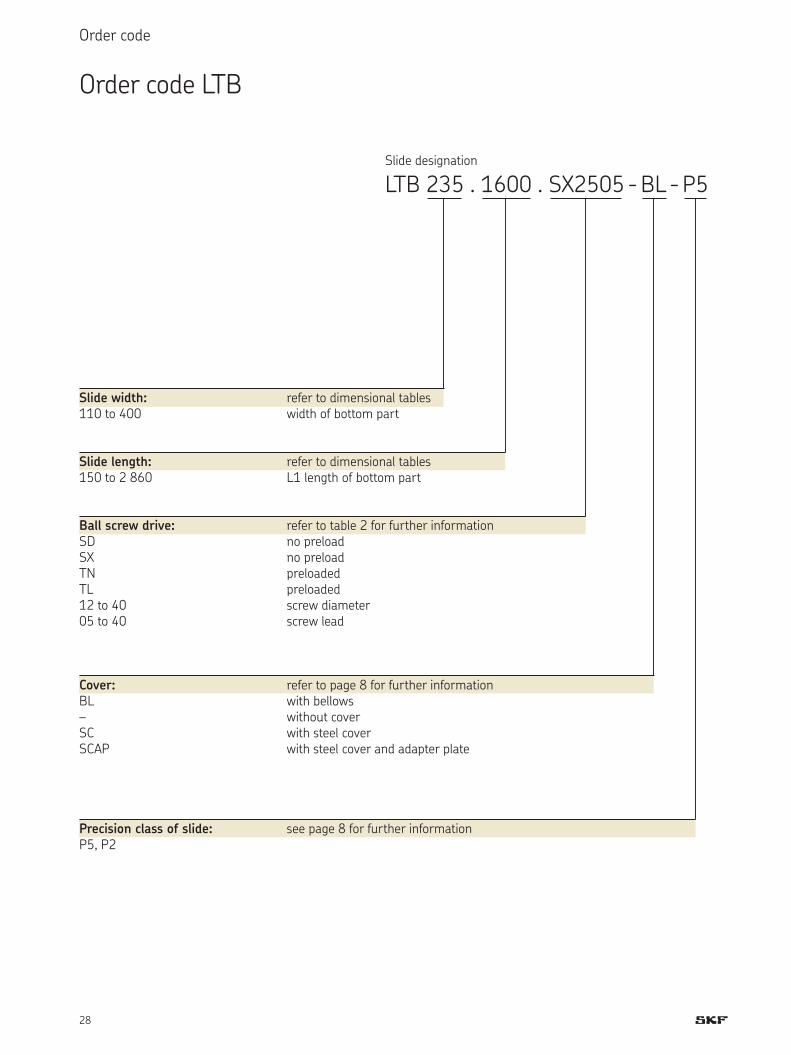
Slide designation LTB 235 . 1600 . SX2505 - BL - P5
Slide width: refer to dimensional tables110 to 400 width of bottom part
Slide length: refer to dimensional tables150 to 2 860 L1 length of bottom part
Ball screw drive: refer to table 2 for further informationSD no preloadSX no preloadTN preloadedTL preloaded12 to 40 screw diameter05 to 40 screw lead
Cover: refer to page 8 for further informationBL with bellows– without coverSC with steel coverSCAP with steel cover and adapter plate
Precision class of slide: see page 8 for further informationP5, P2
Order code LTB

29
Order code
Slide designation LTS 154 . 1900 . 1FN3-050-1K. BL
Slide width: refer to dimensional tables154/ 182/ 212 width of bottom part
Slide length: refer to dimensional tables280 bis 1 960 L1 length of bottom part
Linear motor size: refer to page 7 for further information1FN3-
Cover: refer to page 8 for further informationBL with bellows– without cover
For linear motor slides, the following additional details are required:
Moving mass• Possibly applied additional forces• Maximum and minimum speeds; • maximum accelerationPercentage duty cycle (description of operating cycle)• Requirements of linear encoder: • output signal, positioning resolution or signal period and precision classInformation on motor control• Please ill in the speciication sheet on pages 24 to 26 and return it to us.
Order code LTS

30
SKF – the knowledge engineering company
From the company that invented the self-
align ing ball bearing more than 100 years
ago, SKF has evol ved into a knowledge
engin eering company that is able to draw on
five technology platforms to create unique
solutions for its custom ers. These platforms
include bearings, bearing units and seals, of
course, but extend to other areas including:
lubricants and lubrication sys tems, critical
for long bearing life in many appli cations;
mecha tronics that combine mech anical and
electron ics knowledge into systems for more
effective linear motion and sensorized solu-
tions; and a full range of ser vices, from de-
sign and logistics support to con ditioning
monitoring and reliability systems.
Though the scope has broadened, SKF
continues to maintain the world’s leadership
in the design, manufacture and marketing of
rolling bearings, as well as complementary
products such as radial seals. SKF also holds
an increasingly important position in the
market for linear motion products, high-
precision aerospace bearings, machine tool
spindles and plant maintenance services.
The SKF Group is globally certified to ISO
14001, the international standard for envi r-
o n mental management, as well as OHSAS
18001, the health and safety manage ment
standard. Individual divisions have been
ap proved for quality certification in ac cord-
ance with ISO 9001 and other customer
specific requirements.
With over 100 manufacturing sites
worldwide and sales companies in 70 coun-
tries, SKF is a truly international corpora-
tion. In addition, our distributors and dealers
in some 15 000 locations around the world,
an e-business marketplace and a global
distri bution system put SKF close to custo m-
ers for the supply of both products and
services. In essence, SKF solutions are avail-
able wherever and whenever customers
need them. Over all, the SKF brand and the
corporation are stronger than ever. As the
knowledge engin eering company, we stand
ready to serve you with world-class product
competencies, intellectual resources, and
the vision to help you succeed.
SealsBearings and units
Lubrication systems
Mechatronics Services
Evolving by-wire technology SKF has a unique expertise in fast-growing by-wire technology, from fly-by-wire, to drive-by-wire, to work-by-wire. SKF pioneered practical fly-by-wire technology and is a close working partner with all aerospace industry leaders. As an example, virtually all aircraft of the Airbus design use SKF by-wire systems for cockpit flight control.
SKF is also a leader in automotive by-wire tech-nology, and has partnered with automotive engin-eers to develop two concept cars, which employ SKF mecha tronics for steering and braking. Fur-ther by-wire develop ment has led SKF to produce an all-electric forklift truck, which uses mecha-tronics rather than hydraulics for all controls.
© Airbus – photo: exm company, H. Goussé

31
Harnessing wind powerThe growing industry of wind-generated electric power provides a source of clean, green electricity. SKF is working closely with global industry leaders to develop efficient and trouble-free turbines, providing a wide range of large, highly specialized bearings and condition monitoring systems to extend equip-ment life of wind farms located in even the most remote and inhospitable environments.
Working in extreme environmentsIn frigid winters, especially in northern countries, extreme sub-zero tempera-tures can cause bearings in railway axleboxes to seize due to lubrication star-vation. SKF created a new family of synthetic lubricants formulated to retain their lubrication viscosity even at these extreme temperatures. SKF knowledge enables manufacturers and end user customers to overcome the performance issues resulting from extreme temperatures, whether hot or cold. For example, SKF products are at work in diverse environments such as baking ovens and instant freezing in food processing plants.
Developing a cleaner cleanerThe electric motor and its bearings are the heart of many household appli-ances. SKF works closely with appliance manufacturers to improve their prod-ucts’ performance, cut costs, reduce weight, and reduce energy consumption. A recent example of this cooperation is a new generation of vacuum cleaners with substantially more suction. SKF knowledge in the area of small bearing technology is also applied to manufacturers of power tools and office equipment.
Maintaining a 350 km/h R&D labIn addition to SKF’s renowned research and development facilities in Europe and the United States, Formula One car racing provides a unique environment for SKF to push the limits of bearing technology. For over 50 years, SKF prod-ucts, engineering and knowledge have helped make Scuderia Ferrari a formid-able force in F1 racing. (The average racing Ferrari utilizes more than 150 SKF components.) Lessons learned here are applied to the products we provide to automakers and the aftermarket worldwide.
Delivering Asset Efficiency Optimization Through SKF Reliability Systems, SKF provides a comprehensive range of asset efficiency products and services, from condition monitoring hardware and software to maintenance strategies, engineering assistance and machine reliability programmes. To optimize efficiency and boost productivity, some industrial facil ities opt for an Integrated Maintenance Solution, in which SKF delivers all ser vices under one fixed-fee, performance-based contract.
Planning for sustainable growth By their very nature, bearings make a positive contribution to the natural environment, enabling machinery to operate more efficiently, consume less power, and require less lubrication. By raising the performance bar for our own products, SKF is enabling a new generation of high-efficiency products and equipment. With an eye to the future and the world we will leave to our children, the SKF Group policy on environment, health and safety, as well as the manufacturing techniques, are planned and implemented to help protect and preserve the earth’s limited natural resources. We remain committed to sustainable, environmentally responsible growth.

Bearings and units
SealsLubrication
systems
Mechatronics Services
The Power of Knowledge Engineering
Drawing on five areas of competence and application-specific expertise amassed over more than 100
years, SKF brings innovative solutions to OEMs and production facilities in every major industry world-
wide. These five competence areas include bearings and units, seals, lubrication systems, mechatronics
(combining mechanics and electronics into intelligent systems), and a wide range of services, from 3-D
computer modelling to advanced condition monitoring and reliability and asset management systems.
A global presence provides SKF customers uniform quality standards and worldwide product availability.
skf.com
SKF Linearsysteme GmbH, www.linearmotion.skf.com, [email protected]® SKF is a registered trademark of the SKF Group.© SKF Group 2008The contents of this publication are the copyright of the publisher and may not be reproduced (even extracts) unless permission is gran-ted. Every care has been taken to ensure the accuracy of the information contained in this publication but no liability can be accepted for any loss or damage whether direct, indirectw or consequential arising out of the use of the information contained herein.Publication 6838 / 1 EN · November 2008 This publication supersedes publication 5172.Printed in Germany on environmentally friendly paper.