
ProHeat 35 - ipwl-worldwide.com Proheat 35...ProHeat 35 Processes Description Induction Heating...
78
ProHeat 35 Processes Description Induction Heating Power Source Induction Heating OM-222 166N 2009-03 File: Induction Heating Visit our website at www.MillerWelds.com CE And Non CE Models
-
Upload
vuongthuan -
Category
Documents
-
view
228 -
download
3
Transcript of ProHeat 35 - ipwl-worldwide.com Proheat 35...ProHeat 35 Processes Description Induction Heating...

ProHeat 35
Processes
Description
Induction Heating Power Source
Induction Heating
OM-222 166N 2009−03
File: Induction HeatingVisit our website at
www.MillerWelds.com
CE And Non CE Models

Miller Electric manufactures a full lineof welders and welding related equipment.For information on other quality Millerproducts, contact your local Miller distributor to receive the latest fullline catalog or individual specification sheets. To locate your nearestdistributor or service agency call 1-800-4-A-Miller, or visit us atwww.MillerWelds.com on the web.
Thank you and congratulations on choosing Miller. Now you can getthe job done and get it done right. We know you don’t have time to doit any other way.
That’s why when Niels Miller first started building arc welders in 1929,he made sure his products offered long-lasting value and superiorquality. Like you, his customers couldn’t afford anything less. Millerproducts had to be more than the best they could be. They had to be thebest you could buy.
Today, the people that build and sell Miller products continue thetradition. They’re just as committed to providing equipment and servicethat meets the high standards of quality and value established in 1929.
This Owner’s Manual is designed to help you get the most out of yourMiller products. Please take time to read the Safety precautions. Theywill help you protect yourself against potential hazards on the worksite.
We’ve made installation and operation quickand easy. With Miller you can count on yearsof reliable service with proper maintenance.And if for some reason the unit needs repair,there’s a Troubleshooting section that willhelp you figure out what the problem is. Theparts list will then help you to decide theexact part you may need to fix the problem.Warranty and service information for yourparticular model are also provided.
Miller is the first weldingequipment manufacturer inthe U.S.A. to be registered tothe ISO 9001:2000 QualitySystem Standard.
Working as hard as you do− every power source fromMiller is backed by the mosthassle-free warranty in thebusiness.
From Miller to You
Mil_Thank 4/05

TABLE OF CONTENTS
SECTION 1 − SAFETY PRECAUTIONS − READ BEFORE USING 1. . . . . . . . . . . . . . . . . . . . . . . . . . . . . . . . . . 1-1. Symbol Usage 1. . . . . . . . . . . . . . . . . . . . . . . . . . . . . . . . . . . . . . . . . . . . . . . . . . . . . . . . . . . . . . . . . . . . . . . . 1-2. Induction Heating Hazards 1. . . . . . . . . . . . . . . . . . . . . . . . . . . . . . . . . . . . . . . . . . . . . . . . . . . . . . . . . . . . . 1-3. Additional Symbols for Installation, Operation, and Maintenance 2. . . . . . . . . . . . . . . . . . . . . . . . . . . . . . 1-4. California Proposition 65 Warnings 2. . . . . . . . . . . . . . . . . . . . . . . . . . . . . . . . . . . . . . . . . . . . . . . . . . . . . . . 1-5. Principal Safety Standards 3. . . . . . . . . . . . . . . . . . . . . . . . . . . . . . . . . . . . . . . . . . . . . . . . . . . . . . . . . . . . . 1-6. EMF Information 3. . . . . . . . . . . . . . . . . . . . . . . . . . . . . . . . . . . . . . . . . . . . . . . . . . . . . . . . . . . . . . . . . . . . . .
SECTION 2 − CONSIGNES DE SÉCURITÉ − LIRE AVANT UTILISATION 4. . . . . . . . . . . . . . . . . . . . . . . . . . . . 2-1. Signification des symboles 4. . . . . . . . . . . . . . . . . . . . . . . . . . . . . . . . . . . . . . . . . . . . . . . . . . . . . . . . . . . . . 2-2. Dangers relatifs au soudage à l’arc 4. . . . . . . . . . . . . . . . . . . . . . . . . . . . . . . . . . . . . . . . . . . . . . . . . . . . . . 2-3. Dangers supplémentaires en relation avec l’installation, le fonctionnement et la maintenance 5. . . . . . 2-4. Proposition californienne 65 Avertissements 6. . . . . . . . . . . . . . . . . . . . . . . . . . . . . . . . . . . . . . . . . . . . . . . 2-5. Principales normes de sécurité 6. . . . . . . . . . . . . . . . . . . . . . . . . . . . . . . . . . . . . . . . . . . . . . . . . . . . . . . . . . 2-6. Information EMF 6. . . . . . . . . . . . . . . . . . . . . . . . . . . . . . . . . . . . . . . . . . . . . . . . . . . . . . . . . . . . . . . . . . . . . .
SECTION 3 − DEFINITIONS 7. . . . . . . . . . . . . . . . . . . . . . . . . . . . . . . . . . . . . . . . . . . . . . . . . . . . . . . . . . . . . . . . . . . 3-1. Warning Label Definitions 7. . . . . . . . . . . . . . . . . . . . . . . . . . . . . . . . . . . . . . . . . . . . . . . . . . . . . . . . . . . . . . 3-2. Warning Label Definitions (Continued) 8. . . . . . . . . . . . . . . . . . . . . . . . . . . . . . . . . . . . . . . . . . . . . . . . . . . . 3-3. WEEE Label (For Products Sold Within The EU) 9. . . . . . . . . . . . . . . . . . . . . . . . . . . . . . . . . . . . . . . . . . . 3-4. Symbols And Definitions 9. . . . . . . . . . . . . . . . . . . . . . . . . . . . . . . . . . . . . . . . . . . . . . . . . . . . . . . . . . . . . . .
SECTION 4 − INSTALLATION 10. . . . . . . . . . . . . . . . . . . . . . . . . . . . . . . . . . . . . . . . . . . . . . . . . . . . . . . . . . . . . . . . . . 4-1. Serial Number and Rating Label Location 10. . . . . . . . . . . . . . . . . . . . . . . . . . . . . . . . . . . . . . . . . . . . . . . . . 4-2. Specifications 10. . . . . . . . . . . . . . . . . . . . . . . . . . . . . . . . . . . . . . . . . . . . . . . . . . . . . . . . . . . . . . . . . . . . . . . . 4-3. Selecting A Location 10. . . . . . . . . . . . . . . . . . . . . . . . . . . . . . . . . . . . . . . . . . . . . . . . . . . . . . . . . . . . . . . . . . . 4-4. Tipping 11. . . . . . . . . . . . . . . . . . . . . . . . . . . . . . . . . . . . . . . . . . . . . . . . . . . . . . . . . . . . . . . . . . . . . . . . . . . . . . 4-5. Electrical Service Guide 11. . . . . . . . . . . . . . . . . . . . . . . . . . . . . . . . . . . . . . . . . . . . . . . . . . . . . . . . . . . . . . . . 4-6. Connecting 3-Phase Input Power For 460/575 Volt Models 12. . . . . . . . . . . . . . . . . . . . . . . . . . . . . . . . . . . 4-7. Connecting 3-Phase Input Power For 400/460 Volt IEC And CE Models 13. . . . . . . . . . . . . . . . . . . . . . . . 4-8. Power Source Output Connections 14. . . . . . . . . . . . . . . . . . . . . . . . . . . . . . . . . . . . . . . . . . . . . . . . . . . . . . 4-9. Remote 14 Receptacle RC14 Information and Connections 15. . . . . . . . . . . . . . . . . . . . . . . . . . . . . . . . . . 4-10. Remote 14 Socket Information 15. . . . . . . . . . . . . . . . . . . . . . . . . . . . . . . . . . . . . . . . . . . . . . . . . . . . . . . . . . 4-11. Temperature Recorder Receptacle RC9 Information And Connections 16. . . . . . . . . . . . . . . . . . . . . . . . . 4-12. Temperature Recorder Socket Information 16. . . . . . . . . . . . . . . . . . . . . . . . . . . . . . . . . . . . . . . . . . . . . . . . 4-13. Secondary Insulation Protection 17. . . . . . . . . . . . . . . . . . . . . . . . . . . . . . . . . . . . . . . . . . . . . . . . . . . . . . . . . 4-14. 115 Volt AC Duplex Receptacle And Supplementary Protector 18. . . . . . . . . . . . . . . . . . . . . . . . . . . . . . . . 4-15. Locating Thermocouples 18. . . . . . . . . . . . . . . . . . . . . . . . . . . . . . . . . . . . . . . . . . . . . . . . . . . . . . . . . . . . . . . 4-16. Attaching Welded Thermocouples 20. . . . . . . . . . . . . . . . . . . . . . . . . . . . . . . . . . . . . . . . . . . . . . . . . . . . . . . 4-17. Using Contact Thermocouples 21. . . . . . . . . . . . . . . . . . . . . . . . . . . . . . . . . . . . . . . . . . . . . . . . . . . . . . . . . . 4-18. Placing Temperature Probe 21. . . . . . . . . . . . . . . . . . . . . . . . . . . . . . . . . . . . . . . . . . . . . . . . . . . . . . . . . . . . .
SECTION 5 − COMPONENTS AND CONTROLS 22. . . . . . . . . . . . . . . . . . . . . . . . . . . . . . . . . . . . . . . . . . . . . . . . . . 5-1. Controls 22. . . . . . . . . . . . . . . . . . . . . . . . . . . . . . . . . . . . . . . . . . . . . . . . . . . . . . . . . . . . . . . . . . . . . . . . . . . . .
SECTION 6 − SETUP AND OPERATION 23. . . . . . . . . . . . . . . . . . . . . . . . . . . . . . . . . . . . . . . . . . . . . . . . . . . . . . . . 6-1. Safety Equipment 23. . . . . . . . . . . . . . . . . . . . . . . . . . . . . . . . . . . . . . . . . . . . . . . . . . . . . . . . . . . . . . . . . . . . . 6-2. System Description 23. . . . . . . . . . . . . . . . . . . . . . . . . . . . . . . . . . . . . . . . . . . . . . . . . . . . . . . . . . . . . . . . . . . 6-3. Power Source/System Setup 23. . . . . . . . . . . . . . . . . . . . . . . . . . . . . . . . . . . . . . . . . . . . . . . . . . . . . . . . . . . 6-4. Programming 25. . . . . . . . . . . . . . . . . . . . . . . . . . . . . . . . . . . . . . . . . . . . . . . . . . . . . . . . . . . . . . . . . . . . . . . . .
6-4-1. Temperature-Based Control 25. . . . . . . . . . . . . . . . . . . . . . . . . . . . . . . . . . . . . . . . . . . . . . . . . . . . . . . . . . 6-4-1-1. Preheat 25. . . . . . . . . . . . . . . . . . . . . . . . . . . . . . . . . . . . . . . . . . . . . . . . . . . . . . . . . . . . . . . . . . . . . . . 6-4-1-2. Bake-Out 25. . . . . . . . . . . . . . . . . . . . . . . . . . . . . . . . . . . . . . . . . . . . . . . . . . . . . . . . . . . . . . . . . . . . . . 6-4-1-3. PWHT (Post-Weld Heat Treat) 26. . . . . . . . . . . . . . . . . . . . . . . . . . . . . . . . . . . . . . . . . . . . . . . . . . . . 6-4-1-4. Custom Program 27. . . . . . . . . . . . . . . . . . . . . . . . . . . . . . . . . . . . . . . . . . . . . . . . . . . . . . . . . . . . . . . .
6-4-2. Manual Control 31. . . . . . . . . . . . . . . . . . . . . . . . . . . . . . . . . . . . . . . . . . . . . . . . . . . . . . . . . . . . . . . . . . . . . 6-4-3. Remote Control 31. . . . . . . . . . . . . . . . . . . . . . . . . . . . . . . . . . . . . . . . . . . . . . . . . . . . . . . . . . . . . . . . . . . . 6-4-4. Power vs Time Control 31. . . . . . . . . . . . . . . . . . . . . . . . . . . . . . . . . . . . . . . . . . . . . . . . . . . . . . . . . . . . . .

TABLE OF CONTENTS
6-5. Run Status 32. . . . . . . . . . . . . . . . . . . . . . . . . . . . . . . . . . . . . . . . . . . . . . . . . . . . . . . . . . . . . . . . . . . . . . . . . . . 6-5-1. Temperature Based Control 32. . . . . . . . . . . . . . . . . . . . . . . . . . . . . . . . . . . . . . . . . . . . . . . . . . . . . . . . . .
6-5-1-1. Preheat, Bake-Out And PWHT Run Status Screen 32. . . . . . . . . . . . . . . . . . . . . . . . . . . . . . . . . . . 6-5-1-2. Custom Program 32. . . . . . . . . . . . . . . . . . . . . . . . . . . . . . . . . . . . . . . . . . . . . . . . . . . . . . . . . . . . . . . .
6-5-2. Manual Control 33. . . . . . . . . . . . . . . . . . . . . . . . . . . . . . . . . . . . . . . . . . . . . . . . . . . . . . . . . . . . . . . . . . . . . 6-5-3. Remote Control 33. . . . . . . . . . . . . . . . . . . . . . . . . . . . . . . . . . . . . . . . . . . . . . . . . . . . . . . . . . . . . . . . . . . . 6-5-4. Power vs Time Control 33. . . . . . . . . . . . . . . . . . . . . . . . . . . . . . . . . . . . . . . . . . . . . . . . . . . . . . . . . . . . . .
6-6. Parameters 33. . . . . . . . . . . . . . . . . . . . . . . . . . . . . . . . . . . . . . . . . . . . . . . . . . . . . . . . . . . . . . . . . . . . . . . . . . 6-7. Cooler 34. . . . . . . . . . . . . . . . . . . . . . . . . . . . . . . . . . . . . . . . . . . . . . . . . . . . . . . . . . . . . . . . . . . . . . . . . . . . . . 6-8. Real-Time Operation 34. . . . . . . . . . . . . . . . . . . . . . . . . . . . . . . . . . . . . . . . . . . . . . . . . . . . . . . . . . . . . . . . . .
6-9. System Operating Characteristics 37. . . . . . . . . . . . . . . . . . . . . . . . . . . . . . . . . . . . . . . . . . . . . . . . . . . . . . . SECTION 7 − MAINTENANCE 38. . . . . . . . . . . . . . . . . . . . . . . . . . . . . . . . . . . . . . . . . . . . . . . . . . . . . . . . . . . . . . . . .
7-1. Routine Maintenance 38. . . . . . . . . . . . . . . . . . . . . . . . . . . . . . . . . . . . . . . . . . . . . . . . . . . . . . . . . . . . . . . . . . 7-2. Calibration Verification Equipment 39. . . . . . . . . . . . . . . . . . . . . . . . . . . . . . . . . . . . . . . . . . . . . . . . . . . . . . .
7-3. Calibration Verification Procedure 39. . . . . . . . . . . . . . . . . . . . . . . . . . . . . . . . . . . . . . . . . . . . . . . . . . . . . . . . 7-3-1. Initial Set Up 39. . . . . . . . . . . . . . . . . . . . . . . . . . . . . . . . . . . . . . . . . . . . . . . . . . . . . . . . . . . . . . . . . . . . . . . 7-3-2. TC Input/Output Check 39. . . . . . . . . . . . . . . . . . . . . . . . . . . . . . . . . . . . . . . . . . . . . . . . . . . . . . . . . . . . . . 7-3-3. Finishing Procedure 39. . . . . . . . . . . . . . . . . . . . . . . . . . . . . . . . . . . . . . . . . . . . . . . . . . . . . . . . . . . . . . . .
SECTION 8 − SAFETY PRECAUTIONS FOR SERVICING 43. . . . . . . . . . . . . . . . . . . . . . . . . . . . . . . . . . . . . . . . . . 8-1. Symbol Usage 43. . . . . . . . . . . . . . . . . . . . . . . . . . . . . . . . . . . . . . . . . . . . . . . . . . . . . . . . . . . . . . . . . . . . . . . . 8-2. Servicing Hazards 43. . . . . . . . . . . . . . . . . . . . . . . . . . . . . . . . . . . . . . . . . . . . . . . . . . . . . . . . . . . . . . . . . . . . 8-3. California Proposition 65 Warnings 44. . . . . . . . . . . . . . . . . . . . . . . . . . . . . . . . . . . . . . . . . . . . . . . . . . . . . . . 8-4. EMF Information 44. . . . . . . . . . . . . . . . . . . . . . . . . . . . . . . . . . . . . . . . . . . . . . . . . . . . . . . . . . . . . . . . . . . . . .
SECTION 9 − DIAGNOSTICS & TROUBLESHOOTING 45. . . . . . . . . . . . . . . . . . . . . . . . . . . . . . . . . . . . . . . . . . . . 9-1. Operator Interface Indicators 45. . . . . . . . . . . . . . . . . . . . . . . . . . . . . . . . . . . . . . . . . . . . . . . . . . . . . . . . . . . . 9-2. Limit Conditions 46. . . . . . . . . . . . . . . . . . . . . . . . . . . . . . . . . . . . . . . . . . . . . . . . . . . . . . . . . . . . . . . . . . . . . . . 9-3. Limit Condition Codes 46. . . . . . . . . . . . . . . . . . . . . . . . . . . . . . . . . . . . . . . . . . . . . . . . . . . . . . . . . . . . . . . . . 9-4. Fault Conditions 47. . . . . . . . . . . . . . . . . . . . . . . . . . . . . . . . . . . . . . . . . . . . . . . . . . . . . . . . . . . . . . . . . . . . . . 9-5. Fault Condition Codes 47. . . . . . . . . . . . . . . . . . . . . . . . . . . . . . . . . . . . . . . . . . . . . . . . . . . . . . . . . . . . . . . . .
9-6. System Diagnostic Screens 48. . . . . . . . . . . . . . . . . . . . . . . . . . . . . . . . . . . . . . . . . . . . . . . . . . . . . . . . . . . . 9-7. Removing Wrapper and Measuring Input Capacitor Voltage 50. . . . . . . . . . . . . . . . . . . . . . . . . . . . . . . . . . 9-8. Blowing Out Inside Of Unit 51. . . . . . . . . . . . . . . . . . . . . . . . . . . . . . . . . . . . . . . . . . . . . . . . . . . . . . . . . . . . . .
SECTION 10 − ELECTRICAL DIAGRAM 52. . . . . . . . . . . . . . . . . . . . . . . . . . . . . . . . . . . . . . . . . . . . . . . . . . . . . . . . . SECTION 11 − PARTS LIST 54. . . . . . . . . . . . . . . . . . . . . . . . . . . . . . . . . . . . . . . . . . . . . . . . . . . . . . . . . . . . . . . . . . . . WARRANTY

243165
DECLARATION OF CONFORMITY
for European Community (CE marked) products.
MILLER Electric Mfg. Co., 1635 Spencer Street, Appleton, WI 54914 U.S.A. declares that
the product(s) identified in this declaration conform to the essential requirements and
provisions of the stated Council Directive(s) and Standard(s).
Product/Apparatus Identification:
Product Stock Number
PROHEAT 35 W/TEMPERATURE CONTROL 400460 VOLT, CE 907432
Council Directives:
2006/95/EC Low Voltage
2004/108/EC Electromagnetic Compatibility
2006/42/EEC Machinery Directive
Standards:
IEC 609741 Arc Welding Equipment Welding Power Sources: edition 3, 200507.
IEC 6097410 Arc Welding Equipment Electromagnetic Compatibility Requirements: edition 1.1,
200410.
US Signatory:
February 19, 2009
________________________________________________________________________
David A. Werba Date of Declaration
MANAGER, PRODUCT DESIGN COMPLIANCE


OM-222 166 Page 1
SECTION 1 − SAFETY PRECAUTIONS − READ BEFORE USINGihom _2007−04
Protect yourself and others from injury — read and follow these precautions.
1-1. Symbol Usage
DANGER! − Indicates a hazardous situation which, ifnot avoided, will result in death or serious injury. Thepossible hazards are shown in the adjoining symbolsor explained in the text.
Indicates a hazardous situation which, if not avoided,could result in death or serious injury. The possiblehazards are shown in the adjoining symbols or ex-plained in the text.
NOTICE − Indicates statements not related to personal injury.
� Indicates special instructions.
This group of symbols means Warning! Watch Out! ELECTRICSHOCK, MOVING PARTS, and HOT PARTS hazards. Consult sym-bols and related instructions below for necessary actions to avoid thehazards.
1-2. Induction Heating Hazards
The symbols shown below are used throughout this manualto call attention to and identify possible hazards. When yousee the symbol, watch out, and follow the related instructionsto avoid the hazard. The safety information given below isonly a summary of the more complete safety informationfound in the Safety Standards listed in Section 1-5. Read andfollow all Safety Standards.
Only qualified persons should install, operate, maintain, andrepair this unit.
During operation, keep everybody, especially children, away.
ELECTRIC SHOCK can kill.
Touching live electrical parts can cause fatal shocksor severe burns. The power circuit and output busbars or connections are electrically live wheneverthe output is on. The input power circuit and machine
internal circuits are also live when power is on. Incorrectly installed orimproperly grounded equipment is a hazard.
� Do not touch live electrical parts.
� Enclose any connecting bus bars and coolant fittings to preventunintentional contact.
� Wear dry, hole-free insulating gloves and body protection.
� Insulate yourself from work and ground using dry insulating mats orcovers big enough to prevent any physical contact with the work orground.
� Additional safety precautions are required when any of the follow-ing electrically hazardous conditions are present: in damp locationsor while wearing wet clothing; on metal structures such as floors,gratings, or scaffolds; when in cramped positions such as sitting,kneeling, or lying; or when there is a high risk of unavoidable or ac-cidental contact with the workpiece or ground. For theseconditions, see ANSI Z49.1 listed in Safety Standards. And, do notwork alone!
� Disconnect input power before installing or servicing this equip-ment. Lockout/tagout input power according to OSHA 29 CFR1910.147 (see Safety Standards).
� Use only nonconductive coolant hoses with a minimum length of 18inches (457 mm) to provide isolation.
� Properly install and ground this equipment according to its Owner’sManual and national, state, and local codes.
� Always verify the supply ground − check and be sure that input pow-er cord ground wire is properly connected to ground terminal indisconnect box or that cord plug is connected to a properly groundedreceptacle outlet.
� When making input connections, attach proper groundingconductor first − double-check connections.
� Keep cords dry, free of oil and grease, and protected from hot metaland sparks.
� Frequently inspect input power cord for damage or bare wiring − re-place cord immediately if damaged − bare wiring can kill.
� Turn off all equipment when not in use.
� Do not use worn, damaged, undersized, or poorly spliced cables.
� Do not drape cables over your body.
� Do not touch power circuit if you are in contact with the work, ground,or another power circuit from a different machine.
� Use only well-maintained equipment. Repair or replace damagedparts at once. Maintain unit according to manual.
� Wear a safety harness if working above floor level.
� Keep all panels and covers securely in place.
SIGNIFICANT DC VOLTAGE exists in inverter-typepower sources after removal of input power.� Turn Off inverter, disconnect input power, and discharge input
capacitors according to instructions in Maintenance Section beforetouching any internal parts.
Induction Heating of certain materials, adhesives,and fluxes can produce fumes and gases. Breathingthese fumes and gases can be hazardous to yourhealth.
FUMES AND GASES can be hazardous.
� Keep your head out of the fumes. Do not breathe the fumes.� If inside, ventilate the area and/or use local forced ventilation to re-
move fumes and gases.� If ventilation is poor, wear an approved air-supplied respirator.� Read and understand the Material Safety Data Sheets (MSDSs)
and the manufacturer’s instruction for adhesives, fluxes, metals,consumables, coatings, cleaners, and degreasers.
� Work in a confined space only if it is well ventilated, or while wearingan air-supplied respirator. Always have a trained watchperson near-by. Fumes and gases from heating can displace air and lower theoxygen level causing injury or death. Be sure the breathing air issafe.
� Do not heat in locations near degreasing, cleaning, or spraying oper-ations. The heat can react with vapors to form highly toxic andirritating gases.
� Do not overheat coated metals, such as galvanized, lead, orcadmium plated steel, unless the coating is removed from theheated area, the area is well ventilated, and while wearing an air-supplied respirator. The coatings and any metals containing theseelements can give off toxic fumes if overheated. See coating MSDSfor temperature information.

OM-222 166 Page 2
FIRE OR EXPLOSION hazard.
� Do not overheat parts.� Watch for fire; keep extinguisher nearby.� Keep flammables away from work area.
� Do not locate unit on, over, or near combustible surfaces.
� Do not install unit near flammables.
� Do not operate where the atmosphere may contain flammabledust, gas, or liquid vapors (such as gasoline).
� After completion of work, inspect area to ensure it is free ofsparks, glowing embers, and flames.
� Use only correct fuses or circuit breakers. Do not oversize or by-pass them.
INDUCTION HEATING can cause burns.
� Hot parts and equipment can injure.� Do not touch or handle induction head/coil
during operation.� Do not touch hot parts bare-handed.
� Allow cooling period before handling parts or equipment.
� Keep metal jewelry and other metal personal items away fromhead/coil during operation.
1-3. Additional Symbols for Installation, Operation, and Maintenance
FALLING UNIT can cause injury.
� Use handle and have person of adequatephysical strength lift unit.
� Move unit with hand cart or similar device.� For units without a handle, use equipment of
adequate capacity to lift unit.
� When using lift forks to move unit, be sure forks are long enoughto extend beyond opposite side of unit.
FLYING METAL OR DIRT can injure eyes.
� Wear approved safety glasses with sideshields or wear face shield.
MOVING PARTS can cause injury.
� Keep away from moving parts such as fans.� Keep all doors, panels, covers, and guards
closed and securely in place.
MAGNETIC FIELDS can affect ImplantedMedical Devices.
� Wearers of Pacemakers and other ImplantedMedical Devices should keep away.
� Implanted Medical Device wearers should consult their doctorand the device manufacturer before going near arc welding, spotwelding, gouging, plasma arc cutting, or induction heatingoperations.
OVERUSE can cause OVERHEATING
� Allow cooling period.� Reduce output or reduce duty cycle before
starting to heat again.� Follow rated duty cycle.
STATIC (ESD) can damage PC boards.
� Put on grounded wrist strap BEFORE handlingboards or parts.
� Use proper static-proof bags and boxes tostore, move, or ship PC boards.
H.F. RADIATION can cause interference.
� High-frequency (H.F.) can interfere with radionavigation, safety services, computers, andcommunications equipment.
� Have only qualified person familiar with electronic equipment per-form this installation.
� The user is responsible for having a qualified electrician promptlycorrect any interference problem resulting from the installation.
� If notified by the FCC about interference, stop using the equip-ment at once.
� Have the installation regularly checked and maintained.
� Keep high-frequency source doors and panels tightly shut.
READ INSTRUCTIONS.
� Read Owner’s Manual before using or servic-ing unit.
� Use only genuine replacement parts from themanufacturer.
1-4. California Proposition 65 Warnings
Welding or cutting equipment produces fumes or gaseswhich contain chemicals known to the State of California tocause birth defects and, in some cases, cancer. (CaliforniaHealth & Safety Code Section 25249.5 et seq.)
Battery posts, terminals and related accessories contain leadand lead compounds, chemicals known to the State ofCalifornia to cause cancer and birth defects or otherreproductive harm. Wash hands after handling.
For Gasoline Engines:
Engine exhaust contains chemicals known to the State ofCalifornia to cause cancer, birth defects, or other reproduc-tive harm.
For Diesel Engines:
Diesel engine exhaust and some of its constituents are knownto the State of California to cause cancer, birth defects, andother reproductive harm.

OM-222 166 Page 3
1-5. Principal Safety Standards
Safety in Welding, Cutting, and Allied Processes, ANSI Standard Z49.1,from Global Engineering Documents (phone: 1-877-413-5184, website:www.global.ihs.com).OSHA, Occupational Safety and Health Standards for General Industry,Title 29, Code of Federal Regulations (CFR), Part 1910, Subpart Q, andPart 1926, Subpart J, from U.S. Government Printing Office, Superinten-dent of Documents, P.O. Box 371954, Pittsburgh, PA 15250-7954(phone: 1-866-512-1800) (there are 10 Regional Offices—phone for Re-gion 5, Chicago, is 312-353-2220, website: www.osha.gov).National Electrical Code, NFPA Standard 70, from National Fire Protec-tion Association, P.O. Box 9101, Quincy, MA 02269-9101 (phone:617-770-3000, website: www.nfpa.org and www. sparky.org).
Canadian Electrical Code Part 1, CSA Standard C22.1, from CanadianStandards Association, Standards Sales, 5060 Mississauga, Ontario,Canada L4W 5NS (phone: 800-463-6727 or in Toronto 416-747-4044,website: www.csa-international.org).
Safe Practice For Occupational And Educational Eye And Face Protec-tion, ANSI Standard Z87.1, from American National Standards Institute,25 West 43rd Street, New York, NY 10036–8002 (phone: 212-642-4900,website: www.ansi.org).
1-6. EMF Information
Considerations About Induction Heating And The Effects Of Low Fre-quency Electric And Magnetic FieldsThe following is a quotation from the General Conclusions Section of theU.S. Congress, Office of Technology Assessment, Biological Effects ofPower Frequency Electric & Magnetic Fields − Background Paper, OTA-BP-E-53 (Washington, DC: U.S. Government Printing Office, May1989): “. . . there is now a very large volume of scientific findings basedon experiments at the cellular level and from studies with animals andpeople which clearly establish that low frequency magnetic fields can in-teract with, and produce changes in, biological systems. While most ofthis work is of very high quality, the results are complex. Current scientif-ic understanding does not yet allow us to interpret the evidence in asingle coherent framework. Even more frustrating, it does not yet allowus to draw definite conclusions about questions of possible risk or to of-
fer clear science-based advice on strategies to minimize or avoidpotential risks.”To reduce magnetic fields in the workplace, use the following proce-dures:1. Arrange output cable to one side and away from the operator.2. Do not coil or drape output cable around the body.3. Keep power source and cable as far away from the operator as
practical.
About Implanted Medical Devices:Implanted Medical Device wearers should consult their doctor and thedevice manufacturer before performing or going near arc welding, spotwelding, gouging, plasma arc cutting, or induction heating operations. Ifcleared by your doctor, then following the above procedures is recom-mended.

OM-222 166 Page 4
SECTION 2 − CONSIGNES DE SÉCURITÉ − LIRE AVANTUTILISATION
ihom _2007−04fre
Se protéger, ainsi que toute autre personne travaillant sur les lieux, contre les étincelles et le métal chaud.
2-1. Signification des symboles
DANGER! − Indique une situation dangereuse qui si onl’évite pas peut donner la mort ou des blessures graves.Les dangers possibles sont montrés par les symbolesjoints ou sont expliqués dans le texte.
Indique une situation dangereuse qui si on l’évite paspeut donner la mort ou des blessures graves. Les dan-gers possibles sont montrés par les symboles joints ousont expliqués dans le texte.
NOTE − Indique des déclarations pas en relation avec des blessurespersonnelles.
� Indique des instructions spécifiques.
Ce groupe de symboles veut dire Avertissement! Attention! DANGERDE CHOC ELECTRIQUE, PIECES EN MOUVEMENT, et PIECESCHAUDES. Consulter les symboles et les instructions ci-dessous yafférant pour les actions nécessaires afin d’éviter le danger.
2-2. Dangers relatifs au soudage à l’arc
Les symboles présentés ci-après sont utilisés tout au long duprésent manuel pour attirer votre attention et identifier les ris-ques de danger. Lorsque vous voyez un symbole, soyezvigilant et suivez les directives mentionnées afin d’éviter toutdanger. Les consignes de sécurité présentées ci-après ne fontque résumer l’information contenue dans les normes de sécu-rité énumérées à la section 2-5. Veuillez lire et respecter toutesces normes de sécurité.
L’installation, l’utilisation, l’entretien et les réparations nedoivent être confiés qu’à des personnes qualifiées.
Au cours de l’utilisation, tenir toute personne à l’écart et plusparticulièrement les enfants.
UNE DÉCHARGE ÉLECTRIQUE peutentraîner la mort.
Le contact de composants électriques peut provo-quer des accidents mortels ou des brûlures graves.Le circuit électrique et les barres collectrices ou lesconnexions de sortie sont sous tension lorsque
l’appareil fonctionne. Le circuit d’alimentation et les circuits internesde la machine sont également sous tension lorsque l’alimentation estsur marche. Des équipements installés ou reliés à la borne de terre demanière incorrecte sont dangereux.
� Ne pas toucher aux pièces électriques sous tension.
� Protéger toutes les barres collectrices et les raccords de refroidis-sement pour éviter de les toucher par inadvertance.
� Porter des gants isolants et des vêtements de protection secs etsans trous.
� S’isoler de la pièce à couper et du sol en utilisant des housses oudes tapis assez grands afin d’éviter tout contact physique avec lapièce à couper ou le sol.
� D’autres consignes de sécurité sont nécessaires dans les conditionssuivantes : risques électriques dans un environnement humide ou sil’on porte des vêtements mouillés ; sur des structures métalliques tellesque sols, grilles ou échafaudages ; en position coincée comme assi-se, à genoux ou couchée ; ou s’il y a un risque élevé de contactinévitable ou accidentel avec la pièce à souder ou le sol. Dans cesconditions, voir ANSI Z49.1 énuméré dans les normes de sécurité.En outre, ne pas travailler seul !
� Couper l’alimentation d’entrée avant d’installer l’appareil ou d’effec-tuer l’entretien. Verrouiller ou étiqueter la sortie d’alimentation selonla norme OSHA 29 CFR 1910.147(se reporter aux Principales nor-mes de sécurité).
� N’utiliser que des tuyaux de refroidissement non conducteurs ayantune longueur minimale de 457 mm pour garantir l’isolation.
� Installer le poste correctement et le mettre à la terre convenable-ment selon les consignes du manuel de l’opérateur et les normesnationales, provinciales et locales.
� Toujours vérifier la terre du cordon d’alimentation. Vérifier et s’assu-rer que le fil de terre du cordon d’alimentation est bien raccordé à laborne de terre du sectionneur ou que la fiche du cordon est raccor-dée à une prise correctement mise à la terre.
� En effectuant les raccordements d’entrée, fixer d’abord le conduc-teur de mise à la terre approprié et revérifier les connexions.
� Les câbles doivent être exempts d’humidité, d’huile et de graisse;protégez−les contre les étincelles et les pièces métalliques chau-des.
� Vérifier fréquemment le cordon d’alimentation afin de s’assurer qu’iln’est pas altéré ou à nu, le remplacer immédiatement s’il l’est. Un fil ànu peut entraîner la mort.
� L’équipement doit être hors tension lorsqu’il n’est pas utilisé.
� Ne pas utiliser des câbles usés, endommagés, de grosseur insuffi-sante ou mal épissés.
� Ne pas enrouler les câbles autour du corps.
� Ne pas toucher le circuit électrique si l’on est en contact avec la piè-ce, la terre ou le circuit électrique d’une autre machine.
� N’utiliser qu’un matériel en bon état. Réparer ou remplacer sur-le-champ les pièces endommagées. Entretenir l’appareil conformé-ment à ce manuel.
� Porter un harnais de sécurité si l’on doit travailler au-dessus du sol.
� S’assurer que tous les panneaux et couvercles sont correctementen place.
Il reste une TENSION DC NON NÉGLIGEABLE dansles sources de soudage onduleur quand on a coupél’alimentation.� Avant de toucher des organes internes, couper l’onduleur,
débrancher l’alimentation et décharger les condensateursd’alimentation conformément aux instructions indiquées dans lapartie maintenance.
LES FUMÉES ET LES GAZ peuventêtre dangereux.
Le chauffage à induction de certains matériaux,adhésifs et flux génère des fumées et des gaz. Leurinhalation peut être dangereuse pour votre santé.
� Ne pas mettre sa tête au-dessus des vapeurs. Ne pas respirer cesvapeurs.

OM-222 166 Page 5
� À l’intérieur, ventiler la zone et/ou utiliser une ventilation forcée auniveau de l’arc pour l’évacuation des fumées et des gaz.
� Si la ventilation est médiocre, porter un respirateur anti-vapeurs ap-prouvé.
� Lire et comprendre les spécifications de sécurité des matériaux(MSDS) et les instructions du fabricant concernant les adhésifs, lesflux, les métaux, les consommables, les revêtements, les nettoyantset les dégraisseurs.
� Travailler dans un espace fermé seulement s’il est bien ventilé ou enportant un respirateur. Demander toujours à un surveillant dûmentformé de se tenir à proximité. Des fumées et des gaz provenant duchauffage peuvent déplacer l’air, abaisser le niveau d’oxygène etprovoquer des lésions ou des accidents mortels. S’assurer que l’airambiant ne présente aucun danger.
� Ne pas chauffer dans des endroits se trouvant à proximité d’opéra-tions de dégraissage, de nettoyage ou de pulvérisation. La chaleurpeut réagir en présence de vapeurs et former des gaz hautementtoxiques et irritants.
� Ne pas surchauffer des métaux munis d’un revêtement tels quel’acier galvanisé, plaqué au plomb ou au cadmium, à moins que lerevêtement ne soit enlevé de la zone chauffée, que la zone soit bienventilée et, si nécessaire, en portant un respirateur. Les revêtements ettous les métaux contenant ces éléments peuvent dégager des fuméestoxiques s’ils sont surchauffés. Voir les informations concernant latempérature dans les spécifications de revêtement MSDS.
Risque D’INCENDIE OU D’EXPLO-SION.� Ne pas surchauffer les composants .� Attention aux risques d’incendie: tenir un ex-
tincteur à proximité.
� Stocker des produits inflammables hors de la zone de travail.
� Ne pas placer l’appareil sur, au-dessus ou à proximité de surfacesinflammables.
� Ne pas installer l’appareil à proximité de produits inflammables.
� Ne pas faire fonctionner l’appareil si l’air ambiant est chargé de parti-cules, gaz, ou vapeurs inflammables (vapeur d’essence, parexemple).
� Une fois le travail achevé, assurez−vous qu’il ne reste aucune traced’étincelles incandescentes ni de flammes.
� Utiliser exclusivement des fusibles ou coupe−circuits appropriés.Ne pas augmenter leur puissance; ne pas les ponter.
LE CHAUFFAGE PAR INDUCTION peutprovoquer des brûlures.
� Des pièces ou de l’équipement chaud peuventprovoquer des blessures.
� Ne pas toucher ou manipuler la tête/l’enroulement à induction pen-dant le fonctionnement.
� Ne pas toucher des parties chaudes à mains nues.
� Laisser refroidir les composants ou équipements avant de les mani-puler.
� Tenir les bijoux et autres objets personnels en métal éloignés de latête/de l’enroulement pendant le fonctionnement.
2-3. Dangers supplémentaires en relation avec l’installation, le fonctionnement et lamaintenance
LA CHUTE DE L’APPAREIL peutblesser.
� Utiliser la poignée et demander à une personneayant la force physique nécessaire pour soule-ver l’appareil.
� Déplacer l’appareil à l’aide d’un chariot ou d’unengin similaire.
� Pour les appareils sans poignée utiliser un équipement d’une ca-pacité appropriée pour soulever l’appareil.
� En utilisant des fourches de levage pour déplacer l’unité, s’assu-rer que les fourches sont suffisamment longues pour dépasser ducôté opposé de l’appareil.
DES PIECES DE METAL ou DES SA-LETES peuvent provoquer des bles-sures dans les yeux.
� Porter des lunettes de sécurité à coques latéra-les ou un écran facial.
DES ORGANES MOBILES peuventprovoquer des blessures.
� S’abstenir de toucher des organes mobiles telsque des ventilateurs.
� Maintenir fermés et verrouillés les portes, pan-neaux, recouvrements et dispositifs de protec-tion.
LES CHAMPS MAGNETIQUES peuventaffecter des implants médicaux.
� Porteur de simulateur cardiaque ou autre im-plants médicaux, rester à distance.
� Les porteurs d’implants doivent d’abord consulter leur médecinavant de s’approcher des opérations de soudage à l’arc, de sou-dage par points, de gougeage, du coupage plasma ou de chauf-fage par induction.
L’EMPLOI EXCESSIF peut SUR-CHAUFFER L’ÉQUIPEMENT.
� Prévoir une période de refroidissement� Réduire le courant de sortie ou le facteur de mar-
che avant de recommencer le chauffage.
� Respecter le cycle opératoire nominal.
LES CHARGES ÉLECTROSTATIQUESpeuvent endommager les circuits im-primés.
� Établir la connexion avec la barrette de terreAVANT de manipuler des cartes ou des pièces.
� Utiliser des pochettes et des boîtes antistati-ques pour stocker, déplacer ou expédier descartes PC.

OM-222 166 Page 6
LE RAYONNEMENT HAUTE FRÉ-QUENCE (HF) risque de provoquerdes interférences.
� Le rayonnement haute fréquence (HF) peutprovoquer des interférences avec les équipe-ments de radio-navigation et de communication,les services de sécurité et les ordinateurs.
� Demander seulement à des personnes qualifiées familiariséesavec des équipements électroniques de faire fonctionner l’installa-tion.
� L’utilisateur est tenu de faire corriger rapidement par un électricienqualifié les interférences résultant de l’installation.
� Si le FCC signale des interférences, arrêter immédiatement l’appareil.
� Effectuer régulièrement le contrôle et l’entretien de l’installation.
� Maintenir soigneusement fermés les portes et les panneaux dessources de haute fréquence.
LIRE LES INSTRUCTIONS.
� Lisez le manuel d’instructions avant l’utilisationou la maintenance de l’appareil.
� N’utiliser que les pièces de rechange recom-mandées par le constructeur.
2-4. Proposition californienne 65 Avertissements
Les équipements de soudage et de coupage produisent desfumées et des gaz qui contiennent des produits chimiquesdont l’État de Californie reconnaît qu’ils provoquent des mal-formations congénitales et, dans certains cas, des cancers.(Code de santé et de sécurité de Californie, chapitre 25249.5et suivants).
Les batteries, les bornes et autres accessoires contiennent duplomb et des composés à base de plomb, produits chimiquesdont l’État de Californie reconnaît qu’ils provoquent des can-cers et des malformations congénitales ou autres problèmes deprocréation. Se laver les mains après manipulation.
Pour les moteurs à essence :
Les gaz d’échappement des moteurs contiennent des pro-duits chimiques dont l’État de Californie reconnaît qu’ilsprovoquent des cancers et des malformations congénitalesou autres problèmes de procréation.
Pour les moteurs diesel :
Les gaz d’échappement des moteurs diesel et certains deleurs composants sont reconnus par l’État de Californie com-me provoquant des cancers et des malformationscongénitales ou autres problèmes de procréation.
2-5. Principales normes de sécurité
Safety in Welding, Cutting, and Allied Processes, ANSI Standard Z49.1,de Global Engineering Documents (téléphone : 1-877-413-5184, site In-ternet : www.global.ihs.com).
OSHA, Occupational Safety and Health Standards for General Industry,Title 29, Code of Federal Regulations (CFR), Part 1910, Subpart Q, andPart 1926, Subpart J, from U.S. Government Printing Office, Superinten-dent of Documents, P.O. Box 371954, Pittsburgh, PA 15250-7954(téléphone: 1-866-512-1800) (il y a 10 bureaux régionaux−−le télépho-ne de la région 5, Chicago, est 312-353-2220, site Internet :www.osha.gov).
National Electrical Code, NFPA Standard 70, de National Fire ProtectionAssociation, P.O. Box 9101, Quincy, MA 02269-9101 (téléphone :617-770-3000, site Internet : www.nfpa.org et www.sparky.org).Code électrique du Canada, partie 1, CSA Standard C22.1, from CanadianStandards Association, Standards Sales, 5060 Mississauga, Ontario, Ca-nada L4W 5NS (téléphone : 800-463-6727 ou en Toronto416-747-4044,site internet : www.csa-international.org).
Safe Practice For Occupational And Educational Eye And Face Protec-tion, ANSI Standard Z87.1, de American National Standards Institute, 25West 43rd Street, New York, NY 10036-8002 (téléphone :212-642-4900, site Internet : www.ansi.org).
2-6. Information EMF
Considérations relatives au chauffage à induction et aux effets des champsélectriques et magnétiques basse fréquence.Le texte suivant est extrait des conclusions générales Département duCongrès U.S., Office of Technology Assessment, Effets biologiques deschamps magnétiques et électriques basse fréquence − Background Paper,OTA-BP-E-53 (Washington, DC: U.S. Government Printing Office, May1989): “. . . on dispose maintenant d’importantes découvertes scientifiquesreposant sur des expériences effectuées dans le domaine cellulaire etdes études réalisées sur des animaux et des personnes qui démontrentclairement que des champs magnétiques basse fréquence peuventavoir une interaction et produire des changements dans les systèmesbiologiques. Alors que la plus grande partie de cet ouvrage est d’une trèsgrande qualité, les résultats sont complexes. La compréhension scienti-fique courante ne nous permet pas encore d’interpréter la preuve fourniedans un seul ouvrage cohérent. Il est encore plus frustrant de ne paspouvoir tirer des conclusions définitives en ce qui concerne les problèmesde risque possible ou de proposer des recommandations scientifiques
claires pour des stratégies à suivre en vue de minimiser ou de prévenirdes risques potentiels.”Pour réduire les champs magnétiques sur le poste de travail, appliquerles procédures suivantes :
4. Disposer le câble de sortie d’un côté à distance de l’opérateur
5. Ne pas enrouler ou draper le câble électrique autour du corps.
6. Placer la source de courant et le câble le plus loin possible del’opérateur.
En ce qui concerne les implants médicaux :Les porteurs d’implants doivent d’abord consulter leur médecin avant des’approcher des opérations de soudage à l’arc, de soudage par points,de gougeage, du coupage plasma ou de chauffage par induction. Si lemédecin approuve, il est recommandé de suivre les procédures précé-dentes.

OM-222 166 Page 7
SECTION 3 − DEFINITIONS
3-1. Warning Label Definitions
Warning! Watch Out! There arepossible hazards as shown by thesymbols.
1 Electric shock from wiring cankill.
1.1 Wear dry insulating gloves.Do not wear wet or damagedgloves.
1.2 Disconnect input plug orpower before working onmachine.
2 Induction heating can causeinjury or burns from hot itemssuch as rings, watches, orparts.
2.1 Do not wear metal jewelry andother metal personal itemssuch as rings and watchesduring operation.
2.2 Do not touch hot parts or hothead/coil.
3 Induction heating sparks cancause fire. Do not overheatparts and adhesives.
3.1 Keep flammables away fromheating operation. Do not heatnear flammables.
3.2 Heating sparks can causefires. Have a fire extinguishernearby and have awatchperson ready to use it.
4 Breathing heating fumes canbe hazardous to your health.Read Material Safety DataSheets (MSDSs) andmanufacturer’s instructions formaterial used.
4.1 Keep your head out of thefumes.
4.2 Use forced ventilation or localexhaust to remove the fumes.
4.3 Use ventilating fan to removefumes.
5 Always wear safety glassesor goggles during and aroundheating operations to preventpossible injury.
5.1 Wear either safety glasses orfull goggles depending ontype of operation and nearbyprocesses.
6 Do not remove or paint over(cover) the label.
7 Become trained and read theinstructions before working onthe machine or heating.
190 025

OM-222 166 Page 8
3-2. Warning Label Definitions (Continued)
1 Warning! Watch Out! Thereare possible hazards asshown by the symbols.
2 Electric shock from wiring cankill.
3 Overuse can causeoverheating. Follow rated dutycycle.
4 Disconnect input plug orpower before working onmachine.
5 Become trained and read theinstructions before working onthe machine.
6 Connect green orgreen/yellow groundingconductor to ground terminal.
7 Connect input conductors (L1,L2 And L3) to line terminals.
194 466
1 2
4 5
3
6
7
227 085-A
1 2 3 4 1 Warning! Watch Out! Thereare possible hazards asshown by the symbols.
2 Electric shock from wiring cankill.
3 Disconnect input plug orpower before working onmachine.
4 Do not touch inputcapacitor(s). Allow time forcapacitor(s) to discharge.Check input capacitor(s)voltage (see Section 9-7).

OM-222 166 Page 9
3-3. WEEE Label (For Products Sold Within The EU)
Do not discard product (where ap-plicable) with general waste.
Reuse or recycle Waste Electricaland Electronic Equipment (WEEE)by disposing at a designated collec-tion facility.
Contact your local recycling officeor your local distributor for furtherinformation.
3-4. Symbols And Definitions� Some symbols are found only on CE products.
A Amperes V Volts Alternating Current X Duty Cycle
IP Degree OfProtection Hz Hertz Circuit Protection Output
Increase Line Connection I1 Primary Current I2 Rated Current
U1 Primary Voltage U2 Load Voltage Read Instructions
Three Phase StaticFrequency Con-
verter-Transform-er-Frequency Con-
verter
I1maxRated MaximumSupply Current P1max
Maximum PowerConsumption Three Phase Percent
Remote Panel/Local High Temperature Voltage Input
Off On

OM-222 166 Page 10
SECTION 4 − INSTALLATION
4-1. Serial Number and Rating Label LocationThe serial number and rating information for the power source is located on the front of the machine. Use the rating labels to determine input powerrequirements and/or rated output. For future reference, write serial number in space provided on back cover of this manual.
4-2. Specifications
OutputFrequen
cy
Rated Output RequiredReflectiveInductance
Amperes Input atRated Load Output
50 or 60 Hz,Three-Phase
OverallDimensions Weight
IPRating
SingleOutput
DualOutput 400 V 460 V 575 V kVA kW
5 To 30kHz
35 kW At100%DutyCycle 350 A(RMS),700 V(RMS)
35 kW At100%DutyCycle700 A
(RMS),700 V(RMS)
2.5 To 50μh 60 A 50 A 40 A 39 37
Length: 36-3/4 in(993 mm)
Width: 21-1/2 in(546 mm)
Height: 29 in(737 mm)
227 lb(103 kg) 23CM
Storage Temperature Range −40� F (−40� C) to 122� F (50� C)
*While idling
4-3. Selecting A Location
1 Lifting Eye
2 Lifting Forks
Use lifting eye or lifting forks tomove unit.
If using lifting forks, extend forksbeyond opposite side of unit.
3 Line Disconnect Device
Locate unit near correct inputpower supply.
! Special installation may berequired where gasoline orvolatile liquids are present −see NEC Article 511 or CECSection 20.
3
18 in(460 mm)
18 in(460 mm)
OR
1
2
Movement
Location And Airflow
803 992-B
12 in(305 mm)
12 in(305 mm)

OM-222 166 Page 11
4-4. Tipping
! Do not move or operate unitwhere it could tip.
4-5. Electrical Service Guide
Failure to follow these electrical service guide recommendations could create an electric shock or fire hazard. These recommenda-tions are for a dedicated branch circuit sized for the rated output and duty cycle of the welding power source.
50 HzThreePhase
60 Hz Three Phase
Input Voltage 400 460 575
Input Amperes At Rated Output 60 50 40
Max Recommended Standard Fuse Or Circuit Breaker Rating In Amperes 1
Circuit Breaker 1, Time-Delay 2 70 61 45
Normal Operating 3 80 70 60
Min Input Conductor Size In AWG 4 6 8 8
Max Recommended Input Conductor Length In Feet (Meters)254(77)
214(65)
334(102)
Min Grounding Conductor Size In AWG 4 8 8 10
Reference: 2005 National Electrical Code (NEC) (including article 630)
1 If a circuit breaker is used in place of a fuse, choose a circuit breaker with time-current curves comparable to the recommended fuse.2 Time-Delay fuses are UL class RK5 .3 Normal Operating (general purpose - no intentional delay) fuses are UL class K5 (up to and including 60 amp), and UL class H ( 65 amp and above).4 Conductor data in this section specifies conductor size (excluding flexible cord or cable) between the panelboard and the equipment per NEC Table
310.16. If a flexible cord or cable is used, minimum conductor size may increase. See NEC Table 400.5(A) for flexible cord and cable requirements.

OM-222 166 Page 12
4-6. Connecting 3-Phase Input Power For 460/575 Volt Models
803 994-C
3/8 in
Tools Needed:
! Installation must meet all Nationaland Local Codes − have only quali-fied persons make this installation.
! Disconnect and lockout/tagout in-put power before connecting inputconductors from unit.
! Make input power connections tothe welding power source first.
! Always connect green or green/yellow conductor to supplygrounding terminal first, and neverto a line terminal.
� The circuitry in this unit automaticallyadapts the power source to theprimary voltage being applied. Checkinput voltage available at site. Thisunit can be connected to either 460 or575 VAC input power.
See rating label on unit and check inputvoltage available at site.
1 Input Power Conductors (CustomerSupplied Cord)
Select size and length of conductors usingSection 4-5. Conductors must comply withnational, state, and local electrical codes.If applicable, use lugs of proper amperagecapacity and correct hole size.
Welding Power Source Input PowerConnections
2 Strain Relief
Route conductors (cord) through strain re-lief and tighten screws.
3 Machine Grounding Terminal
4 Green Or Green/Yellow GroundingConductor
Connect green or green/yellow groundingconductor to welding power sourcegrounding terminal first.
5 Welding Power Source LineTerminals
6 Input Conductors L1 (U), L2 (V) AndL3 (W)
Connect input conductors L1 (U), L2 (V)and L3 (W) to welding power source lineterminals.
Close and secure access door on weldingpower source.
Disconnect Device Input PowerConnections
7 Disconnect Device (switch shown inOFF position)
8 Disconnect Device (Supply)Grounding Terminal
Connect green or green/yellow groundingconductor to disconnect device groundingterminal first.
9 Disconnect Device Line Terminals
Connect input conductors L1 (U), L2 (V)And L3 (W) to disconnect device lineterminals.
10 Over-Current Protection
Select type and size of over-currentprotection using Section 4-5 (fused dis-connect switch shown).
Close and secure door on line disconnectdevice. Remove lockout/tagout device,and place switch in the On position.
GND/PE Earth Ground
7
2
10
8
4
9
1
6
3
43
65

OM-222 166 Page 13
Ref. 804 430-A
Tools Needed:
4-7. Connecting 3-Phase Input Power For 400/460 Volt IEC And CE Models
3/8 in
! Installation must meet all National andLocal Codes − have only qualified per-sons make this installation.
! Disconnect and lockout/tagout inputpower before connecting input con-ductors from unit.
! Make input power connections to thewelding power source first.
! Always connect green or green/yellowconductor to supply grounding termi-nal first, and never to a line terminal.
� The circuitry in this unit automaticallyadapts the power source to the primaryvoltage being applied. Check inputvoltage available at site. This unit can beconnected to either 400 or 460 VAC inputpower.
See rating label on unit and check input volt-age available at site.
1 Input Power Conductors (CustomerSupplied Cord)
Select size and length of conductors usingSection 4-5. Conductors must comply withnational, state, and local electrical codes. Ifapplicable, use lugs of proper amperagecapacity and correct hole size.
Welding Power Source Input Power Con-nections
2 Strain Relief
Route conductors (cord) through strain reliefand tighten screws.
3 Machine Grounding Terminal
4 Green Or Green/Yellow GroundingConductor
Connect green or green/yellow groundingconductor to welding power source groundingterminal first.
5 Welding Power Source Line Terminals
6 Input Conductors L1 (U), L2 (V) And L3(W)
Connect input conductors L1 (U), L2 (V) andL3 (W) to welding power source line terminals.
Close and secure access door on weldingpower source.
Disconnect Device Input Power Connec-tions
7 Disconnect Device (switch shown inOFF position)
8 Disconnect Device (Supply) GroundingTerminal
Connect green or green/yellow groundingconductor to disconnect device grounding ter-minal first.
9 Disconnect Device Line Terminals
Connect input conductors L1 (U), L2 (V) AndL3 (W) to disconnect device line terminals.
10 Over-Current Protection
Select type and size of over-current protectionusing Section 4-5 (fused disconnect switchshown).
Close and secure door on line disconnect de-vice. Remove lockout/tagout device, andplace switch in the On position.
7
8
1
54 23
4
L1
L2
L3
6
9
10
= GND/PE Earth Ground3
6

OM-222 166 Page 14
Ref. 803 993-C / Ref. 804 217-A
4-8. Power Source Output Connections
1 Output Connector 1
2 Output Connector 2
3 Protective Plug
4 Air-Cooled Extension Cable
5 Liquid-Cooled Extension Cable
The power source is capable of single ordual output. When connected for singlepower output, up to 35 kW is available atthe single output connection. Whenconnected for dual power, output power isdivided between the two outputconnections.
! Do not move or disconnect cableswhile output is on.
Single Air-Cooled Output Connection
Connect air-cooled output extension cableto Output Connector 1 or OutputConnector 2. Connect Protective Plug toremaining Output Connector.
Single Liquid-Cooled Output Connection
Connect liquid-cooled output extensioncable to Output Connector 1 or OutputConnector 2. Connect Protective Plug toremaining Output Connector.
Dual Air-Cooled Output Connection
Connect air-cooled output extensioncables to Output Connector 1 and OutputConnector 2.
� Extension cables must be the samelength: 25 ft (7.6 m), 50 ft (15.2 m), or75 ft (22.8 m).
� Blankets must be the same size.
Dual Liquid-Cooled Output Connection
Connect liquid-cooled output extensioncables to Output Connector 1 and OutputConnector 2.
� Extension cables must be the samelength: 10 ft (3 m), 25 ft (7.6 m), or 50ft (15.2 m).
� Heating cables must be the samelength: 30ft (9.1 m), 50 ft (15.2 m), 80ft(24.2 m), or 140 ft (42.7 m).
� Total length of heating and extensioncables must not exceed 360 ft (110 m).The extension cable is counted twicethe length because it has a supply andreturn hose.
12
12
Single Air-CooledOutput Connection
Dual Air-CooledOutput Connection
Dual Liquid-CooledOutput Connection
34
44
55
12
12
Single Liquid-CooledOutput Connection
12
3
5
12

OM-222 166 Page 15
803 993-C
4-9. Remote 14 Receptacle RC14 Information and Connections1 Plug
2 Threaded Collar
3 Keyway
4 Remote 14 Receptacle RC14(See Section 4-10)
To connect to receptacle, align key-way, insert plug and tightenthreaded collar.
A JB
K I
C L N H
D M G
E F
3
4
2
1
12
4-10. Remote 14 Socket Information
Socket Socket Information
A
BRemote Contactor
+24 volts dc.
Contact closure to A completes 24 volts dc contactor control circuit.
C
D
E
G
Remote Output Control
Command reference; +10 volts dc.
Control circuit common.
Input command signal (potentiometer wiper or 0 to +10 volts dc).
Not used.
F, J Power Source LimitAbsence of internal contact closure between F and J signals power source error to remotecontrol device.
H
I
L
M
N
K
Remote Metering
Not used.
Actual frequency output signal (1 volt/10 kHz).
Average power output signal (1 volt/10 kW).
Voltage output signal RMS (1 volt/100 volts).
Total current output signal RMS (1 volt/100 amperes).
Chassis common.

OM-222 166 Page 16
803 993-C
4-11. Temperature Recorder Receptacle RC9 Information And Connections1 Plug
2 Threaded Collar
3 Temperature RecorderReceptacle RC9 (See Section4-12)
To connect to receptacle, insertplug and tighten threaded collar.
3
2
1
12
4-12. Temperature Recorder Socket Information
Socket No. Socket Information
1 Thermocouple No. 1 (TC1), 0-10 volt dc signal [0V = −50° F (−46° C), 10V = 1500° F (816° C)]
2 Thermocouple No. 2 (TC2), 0-10 volt dc signal [0V = −50° F (−46° C), 10V = 1500° F (816° C)]
3 Thermocouple No. 3 (TC3), 0-10 volt dc signal [0V = −50° F (−46° C), 10V = 1500° F (816° C)]
4 Thermocouple No. 4 (TC4), 0-10 volt dc signal [0V = −50° F (−46° C), 10V = 1500° F (816° C)]
5 Signal Common
6 Thermocouple No. 5 (TC5), 0-10 volt dc signal [0V = −50° F (−46° C), 10V = 1500° F (816° C)]
7 Thermocouple No. 6 (TC6), 0-10 volt dc signal [0V = −50° F (−46° C), 10V = 1500° F (816° C)]
8 Unused
9 Unused
10 Chassis Ground
11 Unused
12 Unused
13 Unused
14 Unused
* The voltage to temperature calculation is:
(DC Volts Out x 155) − 50 = °F
(DC Volts Out x 86.1) − 45.4 = °C
The ProHeat display should read ±6 °F or ±3.3 °C.

OM-222 166 Page 17
803 994-B / Ref. 801 826-C / Ref. 801 828-C
4-13. Secondary Insulation Protection
Secondary insulation protectioncircuitry automatically shuts downthe power source output if apotentially hazardous conditionexists at the heating deviceconnected to the power source (e.g.insulation has broken down on aheating blanket causing theconductor to come into contact withthe workpiece or a heating coiltouches the workpiece causing ashort in the output circuit).
The supplied ground lead(s) mustbe connected between theworkpiece and power source toprovide proper secondary insula-tion protection from a short in theoutput circuit.
For single output, only oneground lead is required. For dualoutput , use both ground leads.
1 Receptacles2 Plug
To connect plug, align key with key-way, insert end into receptacle, androtate plug until tight.
3 Handle
4 Magnet
� The secondary isolation magnetmust be in contact with baremetal (free from rust, paint,grease, etc.).
5 Workpiece
Use handle to place magnet on theworkpiece.
3
4
5
1
2

OM-222 166 Page 18
803 993-C
4-14. 115 Volt AC Duplex Receptacle And Supplementary Protector
1 115 VAC 2.5 A Single-PhaseAC Receptacle RC1
2 Supplementary Protector CB1(2.5 A)
The receptacle supplies nominal 115volts ac auxiliary power for use withthe optional digital recorder. Maxi-mum output from receptacle is 2.5amperes.
CB1 protects 115 volt receptacleRC1 from overload. If CB1 opens,RC1 does not work.
1
2
12
4-15. Locating Thermocouples
Thermocouple location is one of the most critical steps in the Heat Treatment Operation.
Thermocouples shall be located as follows to provide a survey of heating uniformly and enable time and temperature control:
1. Locate thermocouples to ensure that the full area of the heat band is monitored.
� The code normally specifies the number of thermocouples to be used based on the pipe diameter.
� The control thermocouple is placed in the plane of the weld (center of the heat zone).
� The control thermocouple is placed at the top of the pipe in a standard pipe joint configuration. In otherapplications, the thermocouple should be located in the hottest portion of the weldment to be stress relieved.
2. Consider all nozzles and other welded attachments that cause potential heat sinks through metal mass or cold spots due to heat convection orconduction, and have additional thermocouples applied.
3. Attach a spare thermocouple beside control thermocouples.
4. Attach thermocouples to ensure uniformity of temperature in both thin and thick workpieces.
5. Physically inspect all thermocouples for continuity and mark them by an identification number corresponding to the recorder channel.
6. Match the drawings of the workpiece indicating the numerous thermocouple locations, controlling thermocouple locations, etc. to weld identifi-cation information.
7. The system is equipped with 3-pin thermocouple connections at the front of the unit. Six thermocouples can be attached to the power source.
� The system is equipped with 3-pin connectors to accommodate shielded extension cables. The shieldedcables protect from electrical interference.
8. Type K thermocouple wire has a positive and negative wire. The positive wire is marked as solid yellow or striped yellow. The connector screwterminals are marked positive and negative. Be sure to attach the wire to the connector with proper polarity.

OM-222 166 Page 19
9. The following describes the thermocouple routing from work to power source.
� Type K thermocouple wire (two wire) is attached directly to the workpiece using aThermocouple Attachment Unit (see next section for information on attaching thermocouples).
� The other end is fitted with a 2-pin type K connector.
� The 2-pin connector plugs into the 3-pin composite extension cable. The extension cable has a six-channel block of 3-pin female connectors. The pin size locates the position of the 2-pin connector on the extension.
� The extension cable contains six, 3-wire bundles of shielded cable.
� The 3-pin male extension cable plugs into the 3-pin female connector on the front of the power source.
804 320-A
1
For temperature control mode, the powersource must have (as a minimum) onethermocouple connected to receptacleTC1. If multiple thermocouples are desired,either use individual thermocouple plugs orthe thermocouple extension cable.
To connect thermocouples to the powersource, proceed as follows:
� Do NOT weld thermocouples to work-piece while thermocouple cable is con-nected to the power source.
Turn Off power source.
1 Power Source
2 Thermocouple Receptacles
3 Individual Thermocouple ExtensionCable
4 Multiple Thermocouple ExtensionCable
Align plug pin(s) with receptacle socket(s)and push plug into receptacle.
2
3
4

OM-222 166 Page 20
4-16. Attaching Welded Thermocouples
� Do NOT weld thermocouples while connected to power source.
1. Attach thermocouples using a portable Thermocouple Attachment Unit (TAU). This unit spot welds thermocouple wire directly to theworkpiece. This method of thermocouple attachment ensures accurate temperature measurement.
2. Clean (file or grind) any loose scale or rust from the workpiece at the places where the wires will be attached.
3. Clean the location for the lead magnet to minimize resistance. Place the magnet as near to the thermocouple positions as possible.
4. Strip 1/4 inch of insulation from the thermocouple wires.
5. Set the output variable control of the TAU to about eighty percent (80%).
6. Grasp one of the stripped wires with the tip of the jaws of the application pliers.
� Don’t touch both wires of the thermocouple to the pliers at the same time when energizing the Thermocouple Attachment Unit. This will causethe thermocouple wire to fuse to the pliers, rather than the workpiece.
7. Press the end of the wire to the workpiece at ninety degrees to the surface, and maintain a firm pressure. Make sure the Thermocouple Attach-ment Unit is charged and wait for the ready light to glow.
8. Press discharge button, and the wire should weld to the workpiece. There will be a sharp crack and a slight arc flash.
9. Repeat the process with the other wire, placing it approximately 1/4 inch away from the first wire. Attach a spare thermocouple, and supportboth thermocouples approximately 18 inches back from the connection with a band or fiber tape.
10. Carefully bend the wire over at right angles. This brings the thermocouple wires out along or parallel to the workpiece. It also tests the strengthof the weld. If the weld shows signs of breaking, remove the wire, restrip the end, and repeat the process.
804 322-A
ThermocoupleWires
Strap Or Tape

OM-222 166 Page 21
4-17. Using Contact ThermocouplesThe welded thermocouples discussed previously can be used for preheating or stress relieving. As an alternative, in preheating applications, a contacttemperature sensor* can be used. This eliminates the need to weld thermocouples and the sensor can be moved during the preheat process to checktemperatures at other locations on the joint.
� Removing the contact probe will display a short duration of heat drop on the temperature recorder, if used.
The contact temperature sensor can be plugged into the thermocouple extension cable or a Type K 25 ft. armored extension cable* can be used. One ofthese extensions is required for each sensor.
In preheating applications, the thermocouple must be placed under the induction coil. Temperatures at the weld joint can be checked with temperaturesensitive crayons to verify the preheat temperature.
Welded thermocouples are normally used in stress relieving applications due to their accuracy.
*See product literature for item part number.
804 321-A
4-18. Placing Temperature Probe
1 Blanket
2 Temperature Probe
Place temperature probe betweenblanket and metal material. Theprobe must be in contact with thematerial being heated. The tip of theprobe should be positioned in theapproximate center of the blanketanywhere along the blanket length.
1
2

OM-222 166 Page 22
SECTION 5 − COMPONENTS AND CONTROLS
5-1. Controls
� When a control panel button is pushedthe yellow lamp lights to indicate ac-tivation.
1 Power Switch
Use switch to turn power source On andOff.
2 TC1−4 Temperature Display
Provides temperature display of thermo-couples 1 through 4.
3 Control Thermocouple LEDs
LEDs indicate which thermocouples (1−4)are used to control the heating process.
4 Temperature Units LEDs
LEDs indicate units for temperature mea-surements (°F or ° C).
5 Fault LED
LED lights to indicate a system fault condi-tion.
6 Limit LED
LED lights to indicate a system limit condi-tion.
7 Heat On LED
LED lights to indicate the power source out-put is energized.
8 Stop Button
Use button to stop a heating process.
9 Hold Button
Use button to hold a heating process.
10 Run Button
Use button to run a heating process.
11 Cursor Button
Use button to move selection cursor in the4 x 40 LCD display (item 18).
12 Program Button
Use button to program the process control.
13 Run Status Button
Use button to display real time operatingstatus.
14 Parameter Button
Use button to display real time powersource operating parameters.
15 Cooler Button
Use button to turn cooler On and Off.
16 Increase Button
Use button to increase values in set-upscreen.
17 Decrease Button
Use button to decrease value in programscreen.
18 4 x 40 LCD Display
Displays programming, runs status, pa-rameter, fault and limit conditions, and trou-bleshooting guide.
19 Thermocouple Input Receptacles
Use receptacles for type K thermocoupleinputs.
803 995-B
1
15
14
13
12
17
16
1811891076543
2
19

OM-222 166 Page 23
SECTION 6 − SETUP AND OPERATION
6-1. Safety Equipment
Wear the following duringoperation:
1 Dry, Insulating Gloves
2 Safety Glasses With SideShields
DO NOT wear rings or watchesduring operation.
sb3.1* 1/94
1 2
6-2. System DescriptionThe ProHeat 35 Induction Heating Power Source is designed to function either as an air-cooled system or a liquid-cooled system. Depending on thesystem type (either air-cooled or liquid-cooled), the power source is automatically configured to operate and provide an output appropriate for the typeof connected heating device.
A special identifier, embedded within the extension cable connector, provides the means for the power source to configure itself by recognizing the typeof extension cable(s) attached to its output connectors.
Designed to provide a single level of output (up to 35 kW), the ProHeat 35 power source has two panel mounted connectors that are connected inparallel to the power source output. This design allows the system to operate with either a single output extension cable or two output extension cables.
If a single output extension cable is used, a protective plug (provided with the system) MUST be placed on the unused output connector or the systemwill not operate. If two output extension cables are used, they both MUST be of the same type (either both air-cooled or both liquid-cooled) or the systemwill not operate (in this case, the protective plug is not used). When two extension cables and heating devices are utilized on the system, the extensioncable lengths and heating devices MUST be identical (see Section 4-8).
The ProHeat 35 is intelligent to the point that it will automatically adjust output power levels if internal system operating parameters or internal tempera-tures reach or exceed specific set limits (see Section 9).
6-3. Power Source/System Setup
To view the System Setup screen, simultaneously press the Parameters Hz
VA
kW and Program buttons and the following screen will appear
on the display:
Degree Units: >�F SYSTEM SETUP
Tolerance...: ±25 Backlight: Yes
Input Type..: K TC Control Mode: Manual
Power Output: 35 KW System Lock: No
System Setup Screen
To change a setting:
� Press the Cursor button to move the cursor to the parameter to be changed
� Press Increase or Decrease button to select desired set-up feature.

OM-222 166 Page 24
Possible selections:
Degree Units: °F / °C
Tolerance: ±5 to 99 in °F (±3 to 55 in °C)
Backlight: Yes / No
Input Type: K TC
Control Mode: Temp / Manual / Remote / Time
Power Output: 1 to 35
System Lock: Yes / No
Degree Units − press the Increase or Decrease buttons to select temperature units. Selection will drive the °F / °C indicator LEDs.
� The factory default is °F.
� Changing from °F to °C will convert stored program values: ramp temperature, soak temperature, ramp rate, and temperature tolerance.
Tolerance − press the Increase or Decrease button to select the desired temperature tolerance.
� The factory default is ±25 °F.
Backlight − press the Increase or Decrease button to turn LCD display backlight On or Off.
� The factory default is On.
Input Type − press the Increase or Decrease button to select the desired temperature input device.
� The factory default and only selection is K TC.
Control Mode − press the Increase or Decrease button to select the desired method of system control, either Temperature, Re-
mote, Manual, or Power vs Time (Time). For more details about methods of control, see Section 6-4.
� The factory default is temperature based control.
Power Output − press the Increase or Decrease button to adjust the maximum power source output.
� The factory default is 35 kW.
System Lock − press the Increase or Decrease button to lock or unlock the operator interface to prevent tampering with any
programs. Yes indicates the system is locked, and No indicates the system is unlocked.
� The factory default is No (unlocked).
� All parameters in System Setup are considered global, and any changes to the system set-up parameters will apply to all programs.
To reset the system back to factory default settings, turn off the power source, and wait until the display goes blank. Turn on the power source. When
the display lights, press and hold the Increase and Decrease buttons. A message will display Press Program to reset factory
defaults. Release the Increase and Decrease buttons, and press the Program button.

OM-222 166 Page 25
6-4. ProgrammingProgramming allows the operator to setup a program for a particular heating process. The selections available are Temperature, Remote, Manual, orPower vs Time (Time).
6-4-1. Temperature-Based ControlTemperature-based control operates the system and controls the heating process based on temperature feedback from thermocouple inputs. Ther-mocouples must be used for this mode of operation or the system will not operate. Within the temperature-based mode there are four differentprocesses available as follows: Preheat, Bakeout, PWHT (Post-Weld Heat Treat), and Custom Program.
Press the Program button to access the programming mode. Use the cursor button to move the cursor to the desired temperature-based process,then press the Program button again to select the process.
6-4-1-1. Preheat
The preheat process is a simple method of heating material to a desired temperature and holding that temperature for a specific period of time.When this process is selected, the following screen will appear on the LCD display:
Mode.......: Preheat
Control TC.: 1
Temperature: 400
Soak Time..: 01:00:00
Preheat Screen
The default position of the cursor is next to Control TC. Press the Increase or Decrease button to select the number of control
thermocouples to be used for the program. Selections are as follows: 1, 1,2, 1,2,3, or 1,2,3,4. TC1 MUST always be a control thermocouple. TC2thru TC4 can be used for controlling or monitoring. When a thermocouple is selected as control, the LED adjacent to the seven-segment displayilluminates.
Use the Cursor button to move the cursor to the desired selection (Temperature or Soak Time), and press the Increase or
Decrease button to change the value to the desired setting.
� The minimum and maximum temperature settings for preheat are 0 and 1450� F (−18 and 788� C). The minimum and maximum soak times are0 and 100 hours. When the system is utilizing air-cooled blankets, the maximum temperature setting is 400� F (204� C). If the program settingis above 400� F (204� C), the following screen will appear on the LCD display when the Run button is pressed:
Maximum Temperature Message Screen
Cannot enter Run mode
Programmed temperature settings
exceed air cooled limits
(400 �F, 204 �C)
6-4-1-2. Bake-Out
The bake-out process allows the operator to program a temperature and soak time as well as a cooling rate from bake-out if desired. When thisprocess is selected, the following screen appears on the display:

OM-222 166 Page 26
Mode......: Bake−Out
Control TC:>1
Soak Temp.: 600 Soak Time: 01:00:00
Cool Temp.: 200 Cool Rate: 600 �/Hr
Bake-Out Screen
The default position of the cursor is next to Control TC. Press the Increase or Decrease button to select the number of control
thermocouples to be used for the program. Selections are as follows: 1, 1,2, 1,2,3, or 1,2,3,4. TC1 MUST always be a control thermocouple. TC2thru TC4 can be used for controlling or monitoring. When a thermocouple is selected as control, the LED adjacent to the seven-segment displayilluminates.
Use the Cursor button to move the cursor to the desired selection (Soak Temperature, Soak Time, Cool Temperature, or Cool Rate), and
press the Increase or Decrease button to change the value to the desired setting.
� The minimum and maximum soak and cool temperature settings for bake-out are 0 and 1450� F(−18 and 788� C). The minimum and maximumsoak times are 0 and 100 hours. The minimum and maximum cool rates are 10 and 9999 �/hr. When the system is utilizing air-cooled blankets,the maximum temperature setting is 400� F(204� C). If the program setting is above 400� F (204� C), the following screen will appear on the LCDdisplay when the Run button is pressed:
Maximum Temperature Message Screen
Cannot enter Run mode
Programmed temperature settings
exceed air cooled limits
(400 �F, 204 �C)
6-4-1-3. PWHT (Post-Weld Heat Treat)
The post-weld heat treat process allows the operator to program a post-weld heat treat where ramp temperature (on increase and decrease) andramp rates are the same. When this process is selected, the following screen appears on the display:
Mode......: PWHT
Control TC:>1,2
Ramp Temp.: 200 Ramp Rate: 600 �/Hr
Soak Temp.: 400 Soak Time: 01:00:00
PWHT Screen
The default position of the cursor is next to Control TC. Press the Increase or Decrease button to select the number of control
thermocouples to be used for the program. Selections are as follows: 1, 1,2, 1,2,3, or 1,2,3,4. TC1 MUST always be a control thermocouple. TC2thru TC4 can be used for controlling or monitoring. When a thermocouple is selected as control, the LED adjacent to the seven-segment displayilluminates.

OM-222 166 Page 27
Use the Cursor button to move the cursor to the desired selection (Ramp Temperature, Ramp Rate, Soak Temperature, or Soak Time),
and press the Increase or Decrease button to change the value to the desired setting.
Figure 6-1. Soak Parameters
Soak Temp Soak Time
Ramp Rate
Ramp Temp
� The minimum and maximum ramp temperature settings for PWHT are 0 and 1450� F (−18 and 788� C). The minimum and maximum ramp ratesare 10 and 9999� F/hr (6 and 5555� C/hr). The minimum and maximum soak temperatures are 0 and 1450� F (−18 and 788 � C). The minimumand maximum soak times are 0 and 100 hours. When the system is utilizing air-cooled blankets, the maximum temperature setting is 400� F (204�C). If the program setting is above 400� F (204� C), the following screen will appear on the LCD display when the Run button is pressed.
Maximum Temperature Message Screen
Cannot enter Run mode
Programmed temperature settings
exceed air cooled limits
(400 �F, 204 �C)
6-4-1-4. Custom Program
In Custom Program, the operator can create a custom program with multiple steps or nonsymmetrical heat treat programs where the heating andcooling rates and temperatures are different. When this process is selected, the following screen appears on the display:
� This is the screen for initial use of the system. Subsequent use of custom program will revert to the last program used.
Mode.......: Custom Program
Segment....: 1
Type.......: End
Control TC.: 1
Custom Program Screen

OM-222 166 Page 28
The default position of the cursor is next to Segment. Press the Increase or Decrease button to increase or decrease the
segment number, unless the segment type is End. In this case, the segment number will advance to segment 1.
Use the Cursor button to move the cursor to the desired selection (Type or Control TC), and press the Increase or Decrease
button to change the value to the desired setting. When the cursor is moved to the Type selection, pressing the Increase or
Decrease button changes the segment type to Step, Ramp, Soak, or End. The functions of each segment type are as follows:
� Step increases the temperature in the part at full-programmed power. A maximum temperature of 1450° F (788° C) can be programmed.
� Ramp increases or decreases the temperature in the part at a controlled rate in degrees per hour. A maximum temperature of 1450° F (788°C) and a maximum rate of 9999° F/hr (5555° C/hr) can be programmed.
� Soak will hold the temperature for a programmed time. The minimum and maximum soak times are 0 and 100 hours.
� End is programmed to indicate the completion of the cycle and termination of output power.
Step Function
When type is set to Step, the following screen appears on the display:
Mode.......: Custom Program
Segment....: 1
Type.......:>Step
Temperature: 600
Custom Program Screen
Use the Cursor button to move the cursor to the Temperature position and the initial temperature can be adjusted using the Increase
or Decrease button.
Pressing the Cursor button again automatically advances the program to the next segment number.
Ramp Function
When type is set to Ramp, the following screen appears on the display:
Mode.......: Custom Program
Segment....: 1
Type.......: Ramp
Temperature: 600 Ramp Rate: 600 �/Hr
Custom Program Screen

OM-222 166 Page 29
Use the Cursor button to move the cursor to the Temperature or Ramp Rate position and use the Increase or Decrease
button to set the desired value.
When the cursor is in the Ramp Rate position, pressing the Cursor button again automatically advances the program to the next segment
number.
Soak Function
When type is set to Soak, the following screen appears on the display:
Mode.......: Custom Program
Segment....: 1
Type.......:>Soak
Soak Time..: 00:01:00
Custom Program Screen
Use the Cursor button to move the cursor to the Soak Time position and use the Increase or Decrease button to set
the desired value.
When the cursor is in the Soak Time position, pressing the Cursor button again automatically advances the program to the next segment
number.
End Function
When type is set to End, the following screen appears on the display:
Mode.......: Custom Program
Segment....:> 2
Type.......: End
Control TC.: 1
Custom Program Screen
The only changeable parameter in the End segment is selecting the number of thermocouples. Use the Cursor button to move the cursor
to the Control TC position. Press the Increase or Decrease button to select the number of control thermocouples to be used for
the program. Selections are as follows: 1, 1,2, 1,2,3, or 1,2,3,4. TC1 MUST always be a control thermocouple. TC2 thru TC4 can be used forcontrolling or monitoring. When a thermocouple is selected as control, the LED adjacent to the seven-segment display illuminates.

OM-222 166 Page 30
A custom program can contain up to 10 segments. To view Program parameters, position the cursor at segment and use the Increase or
Decrease button to advance through the segment numbers until the End segment. When a segment number is changed, appropriate
segment parameter information appears on the display.
Typical 5-Segment Custom Program
Mode.......: Custom Program
Segment....: 1
Type.......:>Step
Temperature: 600
Custom Program Screen
Temperature increases to 600 degrees at full-programmed power.
Mode.......: Custom Program
Segment....: 2
Type.......: Ramp
Temperature:>1250 Ramp Rate: 600 �/Hr
Custom Program Screen
Controlled heating to 1250 degrees F at a ramp of 600 degrees per hour.
Mode.......: Custom Program
Segment....: 3
Type.......: Soak
Soak Time..:>01:00:00
Custom Program Screen
Soak at 1250 degrees F for a period of 1 hour.
Mode.......: Custom Program
Segment....: 4
Type.......:>Ramp
Temperature: 600 Ramp Rate: 600 �/Hr
Custom Program Screen
Controlled cooling to 600 degrees F at a rate of 600 degrees per hour.

OM-222 166 Page 31
Mode.......: Custom Program
Segment....: 5
Type.......: End
Control TC.: 1
Custom Program Screen
End segment ends the heat treat cycle. Controller is programmed to control the process using four thermocouples.
6-4-2. Manual Control
Manual control allows programming of a specific power level for a specific period of time. When this process is selected, the following screen appearson the display:
Mode....: Manual Power..: 0.0 KW
Command.: 0.0 KW Current: 0 A
Run Time: 00:03:00 Voltage: 0 V
Frequency: 4.5 KHz
Manual Program Screen
The only programmable selections are Command power and Run Time. Command can be adjusted to deliver up to 35 KW (based on maximumpower selected in the set-up screen) for a period of up to 99 hours, 59 minutes, 59 seconds.
Power source operating power, current, voltage, and frequency are shown on the right-hand side of the display.
To reset the system back to factory default settings, turn off the power source, and wait until the display goes blank. Turn on the power source. When
the display lights, press and hold the Increase and Decrease buttons. A message will display Press Program to reset factory
defaults. Release the Increase and Decrease buttons, and press the Program button.
6-4-3. Remote Control
If Remote was selected as the control mode in the setup window, the following screen appears for programming:
Mode....: Remote Power..: 0.0 KW
Run Time:>00:03:00 Current: 0 A
Voltage: 0 V
Frequency: 4.5 KHz
Time is the only parameter that can be set. The values are 0 − 99:59:59.
6-4-4. Power vs Time Control
Power vs Time control operates the system and controls the heating process based on programmed time and power.
Press the Program button to access the programming mode. Use the cursor button to move the cursor between Mode, Segment, Type, Power, andTime.
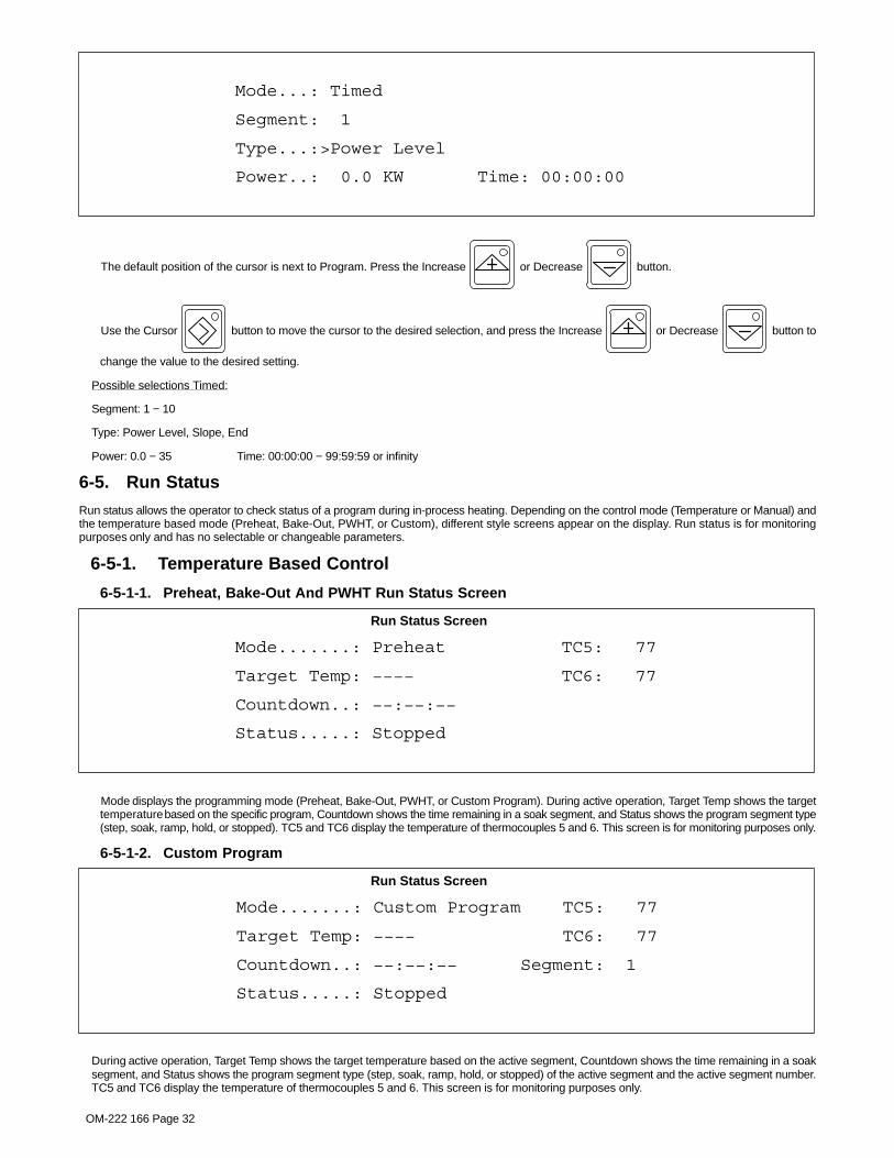
OM-222 166 Page 32
Mode...: Timed
Segment: 1
Type...:>Power Level
Power..: 0.0 KW Time: 00:00:00
The default position of the cursor is next to Program. Press the Increase or Decrease button.
Use the Cursor button to move the cursor to the desired selection, and press the Increase or Decrease button to
change the value to the desired setting.
Possible selections Timed:
Segment: 1 − 10
Type: Power Level, Slope, End
Power: 0.0 − 35 Time: 00:00:00 − 99:59:59 or infinity
6-5. Run Status
Run status allows the operator to check status of a program during in-process heating. Depending on the control mode (Temperature or Manual) andthe temperature based mode (Preheat, Bake-Out, PWHT, or Custom), different style screens appear on the display. Run status is for monitoringpurposes only and has no selectable or changeable parameters.
6-5-1. Temperature Based Control
6-5-1-1. Preheat, Bake-Out And PWHT Run Status Screen
Mode.......: Preheat TC5: 77
Target Temp: −−−− TC6: 77
Countdown..: −−:−−:−−
Status.....: Stopped
Run Status Screen
Mode displays the programming mode (Preheat, Bake-Out, PWHT, or Custom Program). During active operation, Target Temp shows the targettemperature based on the specific program, Countdown shows the time remaining in a soak segment, and Status shows the program segment type(step, soak, ramp, hold, or stopped). TC5 and TC6 display the temperature of thermocouples 5 and 6. This screen is for monitoring purposes only.
6-5-1-2. Custom Program
Mode.......: Custom Program TC5: 77
Target Temp: −−−− TC6: 77
Countdown..: −−:−−:−− Segment: 1
Status.....: Stopped
Run Status Screen
During active operation, Target Temp shows the target temperature based on the active segment, Countdown shows the time remaining in a soaksegment, and Status shows the program segment type (step, soak, ramp, hold, or stopped) of the active segment and the active segment number.TC5 and TC6 display the temperature of thermocouples 5 and 6. This screen is for monitoring purposes only.

OM-222 166 Page 33
6-5-2. Manual Control
Mode.....: Manual TC5: 77
Power....: 0.0 KW TC6: 77
Countdown: −−:−−:−−
Status...: Stopped
Run Status Screen
During active operation, Power shows the actual power delivered from the power source, Countdown shows the time remaining in the heating cycle,and Status indicates if the system is running or stopped. TC5 and TC6 display the temperature of thermocouples 5 and 6. This screen is formonitoring purposes only.
� No changes can be made to the run status screen, and the Cursor, Increase and Decrease buttons are not functional.
6-5-3. Remote Control
Mode.....: Remote TC5: 77
Power....: 0.0 KW TC6: 77
Countdown: 00:00:00
Status...: Stopped
During active operation, Power shows the actual power delivered from the power source, Countdown shows the time remaining of the heating cycle,and Status indicates if the system is running or stopped. This screen is for monitoring purposes only.
� No changes can be made to the run status screen, and the Cursor, Increase and Decrease buttons are not functional.
6-5-4. Power vs Time Control
Mode...: Power vs Time TC5: 77
Segment: 1 TC6: 77
Type...: End
Power..: 0.0 KW Countdown: 00:00:00
Mode displays the control mode. Also displayed are the present program segment, Segment type, current power level and remaining time of thecurrent segment.
6-6. ParametersDuring active operation, the Parameters screen allows the operator to monitor the power source output operating parameters. These parameters in-clude output power, output amperage, output voltage, and output frequency. In addition, temperatures of thermocouples TC5 and TC6 are alsodisplayed. The Parameters screen is for monitoring purposes only and has no selectable or changeable parameters.

OM-222 166 Page 34
Power....: 0.0 KW TC5: 77
Current..: 0 A TC6: 77
Voltage..: 0 V
Frequency: 4.5 KHz
Parameters Screen
6-7. Cooler
The Cooler button is used to turn the cooler On or Off on systems using liquid-cooled output cables. Systems using liquid-cooled output
cables will not deliver output unless the cooler is On. If the cooler is not started prior to initiating a heating cycle, the system will automatically start the
cooler when the Run button is pressed. Pressing the Stop button does not shut off the cooler. The cooler must be shut off separately
by pressing the Cooler button.
When power source output is energized, the cooler cannot be turned off. If the Cooler button is pressed while output is energized, the follow-
ing screen will appear on the display:
Cooler cannot be turned off
while output is on
Cooler Message Screen
� The Cooler button is inactive when no cooler is detected and no liquid-cooled output cable is attached.
6-8. Real-Time OperationEach time the unit is first turned On it initiates a system check routine that includes verification of communication between circuit boards and checkingfor output isolation faults. During this check routine, all displays and LEDs illuminate and the following screen appears on the display:
ProHeat
Firmware Revision X.XX
Copyright (c) 2005 − 2009
Miller Electric Mfg. Co.
Power Up Message Screen
X.XX indicates the firmware revision number installed in the unit.
If an error is detected during the check routine, the system fault LED illuminates and an error message screen appears on the display (see Section 9-5).
When the check routine is completed successfully, the operator interface defaults to the following:

OM-222 166 Page 35
� The Stop button indicator LED illuminates to indicate no heating cycle is in process.
� The temperature displays indicate actual temperature from the TC’s (thermocouples). If no thermocouples are connected, the displays indi-cate OPEN.
� Control LEDs illuminate to indicate the number of control TC’s in the last program.
� The appropriate degree units (°F or °C) light illuminates.
� The display defaults to the Run Status screen from the last program used and the Run Status button indicator LED illuminates.
� If no fault or limit conditions are present, system status lights are not illuminated.
Once set up is complete for the desired program procedure (see Section 6-3), pressing the Run button will initiate a heating cycle. When a
program run is initiated, the Run button yellow indicator LED illuminates and the Heat On blue indicator LED illuminates to indicate output is
present to the coil. The cycle will continue until the end of the program is reached or the Stop button is pressed.
The system has a hold function that will maintain a temperature or hold the soak time of any active temperature controlled program. Pressing the Hold
button will only activate the hold function while in the run mode. If the system is not in the run mode, the following screen will appear on the
display:
Must be running to enter Hold mode
Hold Message Screen
In addition, when running in Manual operating mode, the Hold button is not functional. If the system is running in Manual operating mode,
pressing the Hold button will cause the following screen to appear on the display:
Hold mode not available when
temperature control is not active
Hold Message Screen

OM-222 166 Page 36
Pressing the Hold button will activate the hold function while running a temperature controlled program. While in the hold mode, the parame-
ters for the program in process can be modified. The cycle will continue after pressing the Run button. A change of program parameters
during the hold will not change the original program. The original program parameters are maintained for the next heating cycle.
To make changes to a program while in run mode, press the Hold button and the yellow indicator LED will illuminate, and the Run
button yellow indicator LED will turn off. When in hold, the system will maintain the actual temperature of the hottest thermocouple while the program isbeing changed.
� Press the Program button and the yellow indicator LED will illuminate. The display will change to show the current mode of opera-
tion or the current segment of a Custom Program.
� Use the Cursor button to move the cursor to the parameter that will be changed.
� Press the Increase or Decrease button to make desired changes.
� Press the Run button to resume program operation and the yellow indicator LED will illuminate, and the Hold button
yellow indicator LED will turn off.
Any program parameter (temperatures, rates, times, or number of TC’s) can be changed while in hold. In a custom based program, any segment num-ber can be changed; however, if the operation of a segment has already been completed in a program, the change to that segment will not affect theprogram function.
� Press the Stop button to end the program.

OM-222 166 Page 37
6-9. System Operating CharacteristicsThe power source delivers a high-frequency alternating current output that energizes the coil creating the magnetic field used to heat the workpiece.The power source output characteristics are a function of the configuration, type and number of coils used as shown in the following table:
Table 6-1. Power Source Output Characteristics
Output Type Maximum Amperage Maximum Voltage Frequency Range
Air Cooled Single and Dual
250 A per output for 15 minutes.After 15 minutes, power steps
down to limit current to 150 am-peres per output for continuous
operation.
700 V 5 − 25.7 kHz
See Note 1 700 V 25.7 − 30 kHz
Single Liquid Cooled350 A 700 V 5 − 20 kHz
See Note 2 700 V 20 − 30 kHz
Dual Liquid Cooled350 A per output/700 A total 700 V 5 − 20 kHz
See Note 2 700 V 20 − 30 kHz
� Note 1: In the frequency rangeof 25.7 to 30 KHz, the maxi-mum output amperage de-creases linearly from 250 downto 175 amperes per output. Re-gardless of frequency, after 15minutes the maximum output isreduced to 150 amperes peroutput.
Max
Am
pera
ge P
er O
utpu
t
Frequency (KHz)5 25.7 300
50
100
150
200
250
300
Air Cooled Output
� Note 2: In the frequency rangeof 20 to 30 KHz, the maximumoutput decreases linearly from350 down to 175 amperes peroutput.
Max
Am
pera
ge P
er O
utpu
t
Frequency (KHz)5 20 300
50
100
150
200
250
300
350
400Liquid Cooled Output
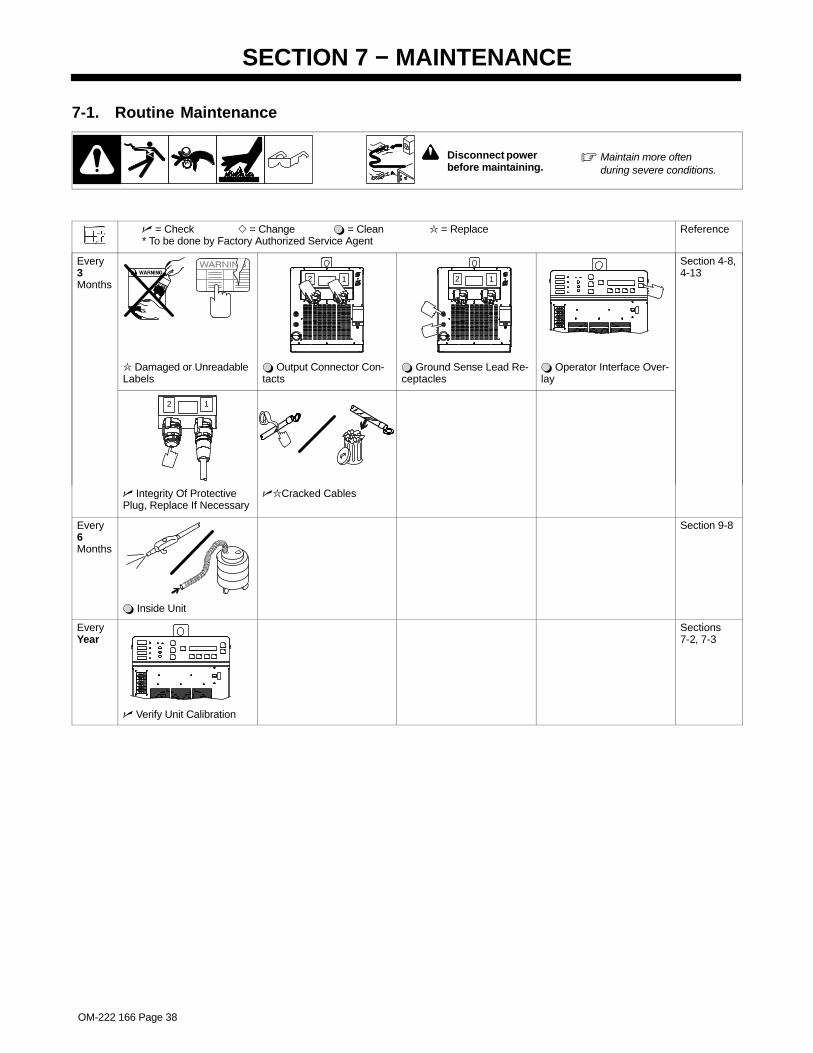
OM-222 166 Page 38
SECTION 7 − MAINTENANCE
7-1. Routine Maintenance
! Disconnect power before maintaining.
� Maintain more oftenduring severe conditions.
� = Check � = Change � = Clean = Replace* To be done by Factory Authorized Service Agent
Reference
Every3Months
12 12
Section 4-8,4-13
Damaged or UnreadableLabels
� Output Connector Con-tacts
� Ground Sense Lead Re-ceptacles
� Operator Interface Over-lay
12
� Integrity Of ProtectivePlug, Replace If Necessary
�Cracked Cables
Every6Months
Section 9-8
� Inside Unit
EveryYear
Sections7-2, 7-3
� Verify Unit Calibration

OM-222 166 Page 39
7-2. Calibration Verification Equipment
1 Thermocoupler CalibratorSuggested calibrator from Fluke item 714or equivalent.2 Type K Mini ConnectorSuggested connector from Fluke item80CK−M or equivalent.A length of type K thermocouple wire isrequired. Connect red to negative and
yellow to positive when wiring connectors.3 Type K 2-Pin Male ConnectorSuggested connector from Newport itemOST−K−M or equivalent4 Calibration LabelSuggested label from Q−CEES itemQCC306BU or equivalent.5 Precision Digital Voltmeter (DVM)
Suggested meters are Agilent Multimeteror Hewlett Packard Multimeter Model34401A or equivalent. DVM must be ableto read to three decimal places (0.000).
6 Interconnecting Cable
MILLER Part No. 300168 can be used toconnect the Recorder to the DC powersupply.
1642 53
7-3. Calibration Verification Procedure
Calibration verification should be done every year. Use appropriate Certificate of Calibration to record calibration information. A spreadsheet could alsobe used to record the information.
7-3-1. Initial Set Up1. Power switch off
2. Have qualified person connect primary power to ProHeat 35.
3. Turn ProHeat 35 power switch on.
4. Press and hold the Program button, then press Parameters to enter setup mode.
5. Press Cursor button 4 times to get to Control Mode line.
6. Press the Decrease button to change to Manual, if necessary.
7. Press the Run Status button. (TC5 and TC6 will show in upper right-hand corner of display)
8. Let unit idle for a minimum of 15 minutes before checking calibration.
9. Turn on Fluke 714 Thermocouple Calibrator and Precision DVM. Leave them on for a minimum of 15 minutes before checking calibration.
7-3-2. TC Input/Output Check1. Connect precision DVM (DC Volts set to display in thousandths) to RC9. This is the top connector located on the back of the ProHeat 35. Red
lead to pin 1 and black to pin 5.
2. Set TC calibrator to 382.0 °F or 194.5 °C. Connect to TC1 input jack on front of ProHeat.
3. Verify TC display value of (±3°F) or (±2°C). RC9 output has a tolerance of (±6°F) or (±3.3°C). DVM reads 2.787 Vdc (±0.038) (2.749 – 2.825).
4. Enter DVM values into calibration certificate If you are creating your own spreadsheet use the following calculation.
The voltage to temperature calculation is:(DC Volts Out x 155) − 50 = °F(DC Volts Out x 86.1) − 45.4 = °C
5. Repeat steps 1.−4. for TC2 – TC6 input jacks.
For TC2 move red precision DVM lead to RC9 pin 2.For TC3 move red precision DVM lead to RC9 pin 3.For TC4 move red precision DVM lead to RC9 pin 4.For TC5 move red precision DVM lead to RC9 pin 6.For TC6 move red precision DVM lead to RC9 pin 7.
Note: TC5 and TC6 will show in upper right-hand corner of display.
6. Repeat steps 1.−5. with TC calibrator set to 882.0 °F or 472.2 °C, verify TC display value (±3°F) or (±2°C). RC9 output has a tolerance of (±6°F)or (±3.3°C). DVM reads 6.013 Vdc (±0.038) (5.975 – 6.041).
7. Repeat steps 1.−5. with TC calibrator set to 1382.0 °F or 750 °C, verify TC display value (±3°F) or (±2°C). RC9 output has a tolerance of (±6°F)or (±3.3°C). DVM reads 9.239 Vdc (±0.038) (9.201 – 9.277).
7-3-3. Finishing Procedure1. If ProHeat 35 was set for Temp in Control Mode follow steps 7-3-1, steps 4.−6. to change it back to Temp.

OM-222 166 Page 40
2. Turn ProHeat 35 power switch off.
3. Have qualified person disconnect primary power.
4. Remove precision DVM and TC calibrator.
5. Complete calibration label & place it on unit directly above TC1 display.I.D. No. (TC board serial number) Be sure the serial number matches the board in the machine.By (your initials) Date (today’s date)Due (date 1 year from today)
6. Print a copy of the certificate to send with the ProHeat 35.
7. If entering data in a spreadsheet, save data.
Notes

OM-222 166 Page 41
do
eshe
reby
cert
ifyth
eab
ove
inst
rum
ent
was
calib
rate
da
gain
stst
anda
rds
and
me
ets
ore
xcee
ds
allp
ublis
hed
spec
ifica
tions
.T
hea
ccur
acy
ofth
ese
sta
nda
rds
isdi
rect
lytr
ace
abl
eto
the
Nat
iona
lIns
titut
eof
Sta
nda
rds
and
Te
chno
logy
.
Vo
lta
ge
Eq
uiv
ale
nt
Vo
lta
ge
Eq
uiv
ale
nt
Vo
ltag
eE
qu
iva
len
tO
ut
(V)
Te
mp
(°F
)O
ut
(V)
Te
mp
(°F
)O
ut
(V)
Te
mp
(°F
)C
HA
NN
EL
1C
HA
NN
EL
2C
HA
NN
EL
3C
HA
NN
EL
4C
HA
NN
EL
5C
HA
NN
EL
6
A−2
321
71−B
09
/09
/08
Ser
ialN
um
be
r:
CE
RT
IFIC
AT
EO
FC
AL
IBR
AT
ION
Ca
libra
tio
nD
ate
:
382
(°F
)P
RIM
AR
YS
TA
ND
AR
D8
82(°
F)
PR
IMA
RY
ST
AN
DA
RD
PR
IMA
RY
ST
AN
DA
RD
Co
mp
any
nam
eC
om
pan
yna
me
TC
ISe
rial
Nu
mb
er:
Ce
rtif
ied
by:
Th
erm
oc
ou
ple
Ca
libra
tor:
Ins
tru
me
nta
tio
nU
sed
:
ma
inta
ine
db
y
Ser
ialN
um
be
r:
138
2(°
F)
Cal
ibra
ted
Mu
ltim
ete
r:
Com
pany
Nam
eS
tre
etP
OB
ox
City
,Sta
te,Z
ipC
ode
Re
−Ca
libra
tio
nD
ate
:

OM-222 166 Page 42
do
eshe
reby
cert
ifyth
eab
ove
inst
rum
ent
was
calib
rate
da
gain
stst
anda
rds
and
me
ets
ore
xcee
ds
allp
ublis
hed
spec
ifica
tions
.T
hea
ccur
acy
ofth
ese
sta
nda
rds
isdi
rect
lytr
ace
abl
eto
the
Nat
iona
lIns
titut
eof
Sta
nda
rds
and
Te
chno
logy
.
A−2
321
71−B
09
/09
/08
Ser
ialN
um
be
r:
CE
RT
IFIC
AT
EO
FC
AL
IBR
AT
ION
Ca
libra
tio
nD
ate
:
Co
mp
any
nam
eC
om
pan
yna
me
TC
ISe
rial
Nu
mb
er:
Ce
rtif
ied
by:
Th
erm
oc
ou
ple
Ca
libra
tor:
Ins
tru
me
nta
tio
nU
sed
:
ma
inta
ine
db
y
Ser
ialN
um
be
r:C
alib
rate
dM
ult
ime
ter:
Com
pany
Nam
eS
tre
etP
OB
ox
City
,Sta
te,Z
ipC
ode
Re
−Ca
libra
tio
nD
ate
:
Vo
lta
ge
Eq
uiv
ale
nt
Vo
lta
ge
Eq
uiv
ale
nt
Vo
lta
ge
Eq
uiv
ale
nt
Ou
t(V
)T
em
p(°
C)
Ou
t(V
)T
em
p(°
C)
Ou
t(V
)T
em
p(°
C)
CH
AN
NE
L1
CH
AN
NE
L2
CH
AN
NE
L3
CH
AN
NE
L4
CH
AN
NE
L5
CH
AN
NE
L6
PR
IMA
RY
ST
AN
DA
RD
47
2(°
C)
PR
IMA
RY
ST
AN
DA
RD
75
0(°
C)
PR
IMA
RY
ST
AN
DA
RD
19
4(°
C)

OM-222 166 Page 43
SECTION 8 − SAFETY PRECAUTIONS FOR SERVICINGProtect yourself and others from injury — read and follow these precautions.
8-1. Symbol UsageOM-222166J - 2007−06, safety_ihtm 2007−04
DANGER! − Indicates a hazardous situation which, ifnot avoided, will result in death or serious injury. Thepossible hazards are shown in the adjoining symbolsor explained in the text.
Indicates a hazardous situation which, if not avoided,could result in death or serious injury. The possiblehazards are shown in the adjoining symbols or ex-plained in the text.
NOTICE − Indicates statements not related to personal injury.
� Indicates special instructions.
This group of symbols means Warning! Watch Out! ELECTRICSHOCK, MOVING PARTS, and HOT PARTS hazards. Consult sym-bols and related instructions below for necessary actions to avoid thehazards.
8-2. Servicing Hazards
The symbols shown below are used throughout this manualto call attention to and identify possible hazards. When yousee the symbol, watch out, and follow the related instructionsto avoid the hazard.
Only qualified persons should service, test, maintain, and re-pair this unit.
During servicing, keep everybody, especially children, away.
ELECTRIC SHOCK can kill.
� Do not touch live electrical parts.� Turn Off induction heating power source and
disconnect and lockout input power using linedisconnect switch, circuit breakers, or by removing plug from recep-tacle, or stop engine before servicing unless the procedure specifi-cally requires an energized unit.
� Insulate yourself from ground by standing or working on dry insulat-ing mats big enough to prevent contact with the ground.
� Do not leave live unit unattended.
� If this procedure requires an energized unit, have only personnelfamiliar with and following standard safety practices do the job.
� When testing a live unit, use the one-hand method. Do not put bothhands inside unit. Keep one hand free.
� Disconnect input power conductors from deenergized supply lineBEFORE moving an induction heating power source.
SIGNIFICANT DC VOLTAGE exists after removal ofinput power on inverters.
� Turn Off inverter, disconnect input power, and discharge inputcapacitors according to instructions in Troubleshooting Section be-fore touching any parts.
STATIC (ESD) can damage PC boards.
� Put on grounded wrist strap BEFORE handlingboards or parts.
� Use proper static-proof bags and boxes tostore, move, or ship PC boards.
FIRE OR EXPLOSION hazard.
� Do not place unit on, over, or near combustiblesurfaces.
� Do not service unit near flammables.
FLYING METAL or DIRT can injure eyes.
� Wear safety glasses with side shields or faceshield during servicing.
� Be careful not to short metal tools, parts, orwires together during testing and servicing.
HOT PARTS can cause severe burns.
� Do not touch hot parts bare handed.� Do not touch or handle induction head/coil
during operation.� Keep metal jewelry and other metal personal
items away from head/coil during operation.
� Allow cooling period before working on equipment.
� To handle hot parts, use proper tools and/or wear heavy, insu-lated welding gloves and clothing to prevent burns.
EXPLODING PARTS can cause injury.
� Failed parts can explode or cause other parts toexplode when power is applied to inverters.
� Always wear a face shield and long sleeveswhen servicing inverters.
SHOCK HAZARD from testing.
� Turn Off induction heating power source be-fore making or changing meter lead connec-tions.
� Use at least one meter lead that has a self-retaining spring clip such as an alligator clip.
� Read instructions for test equipment.
FALLING UNIT can cause injury.
� Use lifting eye to lift unit only, NOT runninggear, gas cylinders, or any other accessories.
� Use equipment of adequate capacity to lift andsupport unit.
� If using lift forks to move unit, be sure forks arelong enough to extend beyond opposite side ofunit.

OM-222 166 Page 44
MOVING PARTS can cause injury.
� Keep away from moving parts such as fans.� Have only qualified persons remove doors,
panels, covers, or guards for maintenance asnecessary.
� Keep hands, hair, loose clothing, and tools away from movingparts.
� Reinstall doors, panels, covers, or guards when maintenance isfinished and before reconnecting input power.
MAGNETIC FIELDS can affect ImplantedMedical Devices.
� Wearers of Pacemakers and other ImplantedMedical Devices should keep away from serv-icing areas until consulting their doctor and thedevice manufacturer.
OVERUSE can cause OVERHEATING.
� Allow cooling period; follow rated duty cycle.� Reduce current or reduce duty cycle before us-
ing induction heating equipment again.� Do not block or filter airflow to unit.
H.F. RADIATION can cause interference.
� High-frequency (H.F.) can interfere with radionavigation, safety services, computers, andcommunications equipment.
� Have only qualified persons familiar withelectronic equipment install, test, and serviceH.F. producing units.
� The user is responsible for having a qualified electrician prompt-ly correct any interference problem resulting from the installa-tion.
� If notified by the FCC about interference, stop using theequipment at once.
� Have the installation regularly checked and maintained.
� Keep high-frequency source doors and panels tightly shut, keepspark gaps at correct setting, and use grounding and shielding tominimize the possibility of interference.
READ INSTRUCTIONS.
� Use Testing Booklet (Part No. 150 853) whenservicing this unit.
� Consult the Owner’s Manual for induction heat-ing safety precautions.
� Use only genuine replacement parts from themanufacturer.
8-3. California Proposition 65 Warnings
Welding or cutting equipment produces fumes or gaseswhich contain chemicals known to the State of California tocause birth defects and, in some cases, cancer. (CaliforniaHealth & Safety Code Section 25249.5 et seq.)
Battery posts, terminals and related accessories contain leadand lead compounds, chemicals known to the State ofCalifornia to cause cancer and birth defects or otherreproductive harm. Wash hands after handling.
For Gasoline Engines:
Engine exhaust contains chemicals known to the State ofCalifornia to cause cancer, birth defects, or other reproduc-tive harm.
For Diesel Engines:
Diesel engine exhaust and some of its constituents areknown to the State of California to cause cancer, birthdefects, and other reproductive harm.
8-4. EMF Information
Considerations About Induction Heating And The Effects Of Low Fre-quency Electric And Magnetic FieldsInduction heating current, as it flows through induction heating cables,will cause electromagnetic fields. There has been and still is someconcern about such fields. However, after examining more than 500studies spanning 17 years of research, a special blue ribbon committeeof the National Research Council concluded that: “The body ofevidence, in the committee’s judgment, has not demonstrated thatexposure to power-frequency electric and magnetic fields is a human-health hazard.” However, studies are still going forth and evidencecontinues to be examined. Until the final conclusions of the research arereached, you may wish to minimize your exposure to electromagneticfields when using induction heating equipment.To reduce magnetic fields in the workplace, use the followingprocedures:
1. Keep cables close together by twisting or taping them, or using acable cover.
2. Arrange cables to one side and away from the operator.
3. Do not coil or drape cables around your body.
4. Keep induction heating power source and cables as far awayfrom operator as practical.
5. Connect work clamp to workpiece as close to the weld aspossible.
About Implanted Medical Devices:
Implanted Medical Device wearers should consult their doctor and thedevice manufacturer before performing or going near arc welding, spotwelding, gouging, plasma arc cutting, or induction heating operations.If cleared by your doctor, then following the above procedures is recom-mended.

OM-222 166 Page 45
SECTION 9 − DIAGNOSTICS & TROUBLESHOOTINGThe ProHeat 35 power source has on-board capabilities to aid in troubleshooting problems should any conditions occur during operation. Thistroubleshooting capability consists of the Fault LED, Limit LED, and message screens that appear on the front panel LCD display.
9-1. Operator Interface Indicators
1 Fault LED
LED lights to indicate a system faultcondition.
2 Limit LED
LED lights to indicate a system limitcondition.
3 4 x 40 LCD Display
Displays programming, run status, param-eters, fault and limit conditions, andtroubleshooting guide.
803 995-B
321

OM-222 166 Page 46
9-2. Limit Conditions
A limit condition indicates that the system has encountered an open thermocouple or is outside the range of its optimum operating conditions orparameters. Should a limit condition occur during operation, the yellow Limit LED will flash to indicate a problem. If the active screen on the LCD displayis Run Status or Parameters, a message describing the particular limit condition will appear on the display. If the active screen is Program, press the
Run Status button to display the limit condition.
In a limit condition, the power source will continue to deliver output power and protect itself from damage by reducing the output power. This situationallows the operator time to determine the best action to correct the problem as described by the limit message on the LCD display.
If a limit condition occurs, there are two selectable options:
� Acknowledge the limit and continue operation.
� Terminate operation to correct the problem causing the limit.
Pressing the Decrease button will acknowledge the limit and continue operation with the existing set up. In the acknowledge state, the yellow
Limit LED will stop flashing and remain on continuously. The LCD display will revert to an active screen once the Program button, Run Status
button, or Parameters Hz
VA
kW button is pressed.
If a new limit condition should occur after the first is acknowledged, the yellow Limit LED will start flashing to indicate a new problem. To display the limit
condition, press the Run Status button and the LCD display will show a message describing the new and previous limit messages.
To obtain additional information regarding the limit condition and suggested solutions to resolve the limit, press the Increase button, and the
LCD display will indicate possible solutions based on the type of limit condition.
If the operator determines that the best course of action is to terminate operation and make suggested changes to the setup to eliminate the limit condi-
tion, press the Stop button. After changes are made to the setup, press the Run button to restart the process.
9-3. Limit Condition Codes
Limit Condition Additional Information
L01: Thermocouple #1 Open Check for open temperature sensor and repairChange to back-up temperature sensor
L02: Themocouple #2 Open Check for open temperature sensor and repairChange to back-up temperature sensor
L03: Thermocouple #3 Open Check for open temperature sensor and repairChange to back-up temperature sensor
L04: Thermocouple #4 Open Check for open temperature sensor and repairChange to back-up temperature sensor
L05: Thermocouple #5 Open Check for open temperature sensor and repairChange to back-up temperature sensor
L06: Thermocouple #6 Open Check for open temperature sensor and repairChange to back-up temperature sensor
L07: Output Voltage Limit Tighten blanket against pipe surface
L08: Output Voltage Limit Increase number of turnsIncrease coil spaceShorten extension cableIncrease insulation width
L09: Output Current Limit Tighten blanket against pipe surface
L10: Output Current Limit Increase number of turnsDecrease coil spaceTighten cable on insulation

OM-222 166 Page 47
Limit Condition Additional Information
L11: Coolant Overtemp Limit Check coolant flow and levelClean coolant filters and heat exchangerIncrease number of turnsVerify appropriate insulation thickness
L12: Power Source Overtemp Limit Check for blocked ventsClean wind tunnel heat sinks
L13: Cable Connection Check for loose/open output connectionVerify all output cables are same typeVerify receptacle plug connected
9-4. Fault ConditionsA fault condition occurs if the system encounters an isolation fault, encounters operating conditions outside operational limits, or if there is a serious
problem with the system. Should a fault condition occur, the output is immediately turned off, the red Fault LED flashes and the Stop button
LED flashes. If the active screen on the LCD display is Run Status or Parameters, a message describing the particular fault condition will appear on the
display. If the active screen is Program, press the Run Status button to display the fault condition.
Pressing the Decrease button will acknowledge the fault and the red Fault LED will stop flashing and remain on continuously. However, the
Stop button LED will continue to flash indicating that the process has stopped.
To obtain additional information regarding the fault condition and suggested solutions to resolve the fault, press the Increase button, and the
LCD display will indicate possible solutions based on the type of fault condition. In most cases, a fault condition will indicate that service is required.
9-5. Fault Condition Codes
Fault Condition Additional Information
F51: Thermocouple #1 Internal Fault Service required
F52: Themocouple #2 Internal Fault Service required
F53: Thermocouple #3 Internal Fault Service required
F54: Thermocouple #4 Internal Fault Service required
F55: Thermocouple #5 Internal Fault Service required
F56: Thermocouple #6 Internal Fault Service required
F57: CJT Sensor Internal Fault Service required
F58: Output Voltage Fault Service required
F59: Output Current Fault Service required
F60: Temperature Sensor Fault Check control TC connectionsCheck control TC extension cable
F61: Coolant Flow Fault Check for coolant leakClean for coolant blockageCheck coolant filter and levelCheck coolant connections
F62: Isolation Fault Check for exposed conductorClean for moisture on cables
F63: Line Voltage Fault Check line voltage
F64: Power Source Overtemp Fault Verify power source vents andwind tunnel are unobstructed
F65: Current Source Fault Service required
F66: Under Frequency Fault Check for loose or open connectionsin output cable
Decrease number of turns
Decrease coil space

OM-222 166 Page 48
Fault Condition Additional Information
F67: Over Frequency Fault Verify heating cable properly wrappedVerify material being heated is magnetic
F68: Cable Connection Fault Check for loose/open output connectionVerify all output cables are same typeVerify receptacle plug connected
F69: Coolant Overtemp Fault Check coolant flow and levelClean coolant filters and heat exchangerIncrease number of turnsVerify appropriate insulation thickness
F70: Internal Communication Fault Service required
F71: Internal Thermistor Fault Service required
F72: Coolant Thermistor Fault Service required
F73: Decoupled/Open Coil Check for loose/open output connection. Tighten coil/blanket.
F74: Isolation Fault Self-Test Error Service required
F75: Internal Power Supply Fault Service required
F76: Current Source Control Fault Service required
F77: Power Source Internal Comm Fault Service required
F78: Output Current Sense Fault Check for loose/open output connection or an extension cable connected with no coil attachedat the end.
9-6. System Diagnostic Screens
Additional system diagnostics are available and accessible through the operator interface. Detail operational parameters can be accessed by pressing
and holding the Run Status button and pressing the Parameters Hz
VA
kW button.
When this feature is initially activated, the following screen appears on the LCD display:
RemCmd: 1023 Off Cable1: LQD DIAG1
OutI1: 0 A Cable2: LQD
OutI2: 0 A ClntFR: 0.75 GPM
IsrcFb: 0 A ClrSts: Flowing
System Diagnostic Screen
RemCmd − This is the value of the remote command and the status of the remote contactor.
� Remote controls can be used to enable/disable output in all control modes. They only affect output power level when the control mode is set toRemote.
Out I1 − This is the value of the output current on output 1.
Out I2 − This is the value of the output current on output 2.
Isrc FB − This is the value of the amperage in the current source inverter.
Cable 1 − This is the cable type hooked up to output number one. Possible labels:
� AIR − for an air-cooled cable
� LQD − for a liquid-cooled cable
� PLUG − for a protective plug
� OPEN − no cable or plug in place
Cable 2 − This is the cable type hooked up to output number two. Possible labels:
� AIR − for an air-cooled cable
� LQD − for a liquid-cooled cable

OM-222 166 Page 49
� PLUG − for a protective plug
� OPEN − no cable or plug in place
ClntFR − This is the coolant flow rate (in GPM) from the cooler on a liquid-cooled system.
ClrSts − This is the status of the cooler. Possible labels:
� Off
� Flowing
The second diagnostic screen is available by again pressing and holding the Run Status button and pressing the Parameters Hz
VA
kW
button.
VLnA−B: 460V Therm1: 75 DIAG2
VLnB−C: 460V Therm2: 75 Therm5: OPEN
VLnC−A: 460V Therm3: 75 ClrTmp: 77
VBus: 650V Therm4: OPEN RmtFlw: Off
System Diagnostic Screen
VLnA-B − This is the phase to phase line voltage between phases A and B.
VLnB-C − This is the phase to phase line voltage between phases B and C.
VLnC-A − This is the phase to phase line voltage between phases C and A.
VBus − This is the DC bus voltage.
Therm1 − This is the temperature of the current source primary heatsink.
Therm2 − This is the temperature of the bridge heatsink.
Therm3 − This the the temperature of the current source secondary heatsink.
Therm4 − Open (not used).
Therm5 − Open (not used).
ClrTmp − This is the temperature of the coolant on a liquid-cooled system.
� OPEN − no cooler is detected.
RmtFlw − This is the status of the relay contacts for remote coolant flow on a liquid-cooled system.
� OFF
� ON
� RmtFlw feature is unsupported on the current platform.

OM-222 166 Page 50
9-7. Removing Wrapper and Measuring Input Capacitor Voltage
! 900 Volts dc can be presenton the capacitor bus andsignificant DC voltage canremain on capacitors afterunit is Off. Always check thevoltage on inverter assemblyas shown to be sure the inputcapacitors have dischargedbefore working on unit.
! Turn Off welding powersource, and disconnectinput power.
! Significant DC voltage canremain on capacitors afterunit is Off. Always check thevoltage as shown to be surethe input capacitors havedischarged before workingon unit.
Remove right side panel and dis-connect fan motor FM3.
1 Current Source InterconnectBoard PC4
2 Voltmeter
Measure the dc voltage across the+ bus terminal and − bus terminal onPC4 as shown until voltage drops tonear 0 (zero) volts.
� If the capacitor voltage doesnot drop to near zero afterseveral minutes, use a bleederresistor of between 200 and500 ohms, at least 10 watts,and #16 AWG 600 volts ac in-sulation rated wire to dischargethe capacitor(s).
3 Typical Bleeder Resistor
An example of a typical bleederresistor is shown on this page.
Proceed with job inside unit. Re-connect FM3 and reinstall right sidepanel when finished.
Tools Needed:
5/16, 3/8 in
804 519-B
1
2
+ lead to right bus terminal,− lead to left bus terminal
3
Typical Bleeder Resistor
#16 AWG 600 Volts ACInsulation Rating
200 to 500 ohm, 10 wattwire wound resistor

OM-222 166 Page 51
9-8. Blowing Out Inside Of Unit
! Turn Off welding powersource and disconnect inputpower.
! Remove wrapper and besure input capacitors aredischarged.
Blow out inside of unit. Blow out fanmotors in right side panel and frontpanel.
804 625-B
Notes
16 Gauge (.063 in)
22 Gauge (.031 in)
24 Gauge (.025 in)
20 Gauge (.037 in)
18 Gauge (.050 in)
14 Gauge (.078 in)
1/8 in (.125 in)
3/16 in (.188 in)
1/4 in (.25 in)
5/16 in (.313 in)
3/8 in (.375 in)
1/2 in (.5 in)
MATERIAL THICKNESS REFERENCE CHART

OM-222 166 Page 52
SECTION 10 − ELECTRICAL DIAGRAM
Figure 10-1. Circuit Diagram

OM-222 166 Page 53
218 057-H

OM-222 166 Page 54
SECTION 11 − PARTS LIST
� Hardware is common andnot available unless listed.
Figure 11-1. WrappersRef. 804 218-D
1
35
6
7
8
11
9
10
11
See Figure11-2
See Figure11-3
4
2
12
13
14
QuantityDescriptionPartNo.
Dia.Mkgs.
ItemNo.
Figure 11-1. Wrappers
1 +217 470 PANEL, side RH 1. . . . . . . . . . . . . . . . . . . . . . . . . . . . . . . . . . . . . . . . . . . . . . . . . . . . . . . . . . . . . . . . . 2 217 860 LABEL, warning electric shock and input pwr (FR) 1. . . . . . . . . . . . . . . . . . . . . . . . . . . . . . . . . . . . . 3 +217 325 COVER, top 1. . . . . . . . . . . . . . . . . . . . . . . . . . . . . . . . . . . . . . . . . . . . . . . . . . . . . . . . . . . . . . . . . . . . . 4 147 876 LABEL, warning general precautionary induction heat 1. . . . . . . . . . . . . . . . . . . . . . . . . . . . . . . . . . 5 217 334 PANEL, side LH 1. . . . . . . . . . . . . . . . . . . . . . . . . . . . . . . . . . . . . . . . . . . . . . . . . . . . . . . . . . . . . . . . . . . 6 217 468 DOOR, primary board 1. . . . . . . . . . . . . . . . . . . . . . . . . . . . . . . . . . . . . . . . . . . . . . . . . . . . . . . . . . . . . . 7 218 280 HINGE, cont polyolefin copolymer 1. . . . . . . . . . . . . . . . . . . . . . . . . . . . . . . . . . . . . . . . . . . . . . . . . . . 8 222 106 BRACKET, mtg fan 1. . . . . . . . . . . . . . . . . . . . . . . . . . . . . . . . . . . . . . . . . . . . . . . . . . . . . . . . . . . . . . . . 9 FM3 236 263 FAN, muffin 24VDC 3000 RPM 130 CFM 1. . . . . . . . . . . . . . . . . . . . . . . . . . . . . . . . . . . . . . . .
10 206 270 INSULATOR, side RH 2. . . . . . . . . . . . . . . . . . . . . . . . . . . . . . . . . . . . . . . . . . . . . . . . . . . . . . . . . . . . . . 11 198 035 HANDLE 1. . . . . . . . . . . . . . . . . . . . . . . . . . . . . . . . . . . . . . . . . . . . . . . . . . . . . . . . . . . . . . . . . . . . . . . . . 12 197 931 MAGNET, permanent 1. . . . . . . . . . . . . . . . . . . . . . . . . . . . . . . . . . . . . . . . . . . . . . . . . . . . . . . . . . . . . . 13 197 900 CABLE, work ground 1. . . . . . . . . . . . . . . . . . . . . . . . . . . . . . . . . . . . . . . . . . . . . . . . . . . . . . . . . . . . . . 14 127 836 PLUG, tw lk insul male 1. . . . . . . . . . . . . . . . . . . . . . . . . . . . . . . . . . . . . . . . . . . . . . . . . . . . . . . . . . . . .
RC2 135 635 HOUSING PLUG+PINS, (service kit) 1. . . . . . . . . . . . . . . . . . . . . . . . . . . . . . . . . . . . . . . . . . . . . . PLG2 131 054 HOUSING RCPT+SKTS, (service kit) 1. . . . . . . . . . . . . . . . . . . . . . . . . . . . . . . . . . . . . . . . . . . .
PLG61 131 204 HOUSING PLUG+SKTS, (service kit) 1. . . . . . . . . . . . . . . . . . . . . . . . . . . . . . . . . . . . . . . . . . . PLG63 115 094 HOUSING PLUG+SKTS, (service kit) 1. . . . . . . . . . . . . . . . . . . . . . . . . . . . . . . . . . . . . . . . . . . .
+When ordering a component originally displaying a precautionary label, the label should also be ordered.To maintain the factory original performance of your equipment, use only Manufacturer’s SuggestedReplacement Parts. Model and serial number required when ordering parts from your local distributor.

OM-222 166 Page 55
� Hardware is common andnot available unless listed.
Figure 11-2. Front Panel
804 219-A
1
2
311
8
12
4
5
13
6
7
910
QuantityDescriptionPartNo.
Dia.Mkgs.
ItemNo.
Figure 11-2. Front Panel
1 217 323 PANEL, front 1. . . . . . . . . . . . . . . . . . . . . . . . . . . . . . . . . . . . . . . . . . . . . . . . . . . . . . . . . . . . . . . . . . . . . 2 216 225 NAMEPLATE, ProHeat 35 1. . . . . . . . . . . . . . . . . . . . . . . . . . . . . . . . . . . . . . . . . . . . . . . . . . . . . . . . . . 3 216 224 PANEL, operator interface 1. . . . . . . . . . . . . . . . . . . . . . . . . . . . . . . . . . . . . . . . . . . . . . . . . . . . . . . . . . 4 TC1−TC6 218 686 RECEPTACLE ASSY, thermocouple 6. . . . . . . . . . . . . . . . . . . . . . . . . . . . . . . . . . . . . . . 5 217 327 PLATE, TC receptacle 1. . . . . . . . . . . . . . . . . . . . . . . . . . . . . . . . . . . . . . . . . . . . . . . . . . . . . . . . . . . . . 6 S1 213 060 SWITCH, tgl 3pst 60 A 600 VAC 1. . . . . . . . . . . . . . . . . . . . . . . . . . . . . . . . . . . . . . . . . . . . . . . . 7 212 810 LABEL, on−off w/symbols 1. . . . . . . . . . . . . . . . . . . . . . . . . . . . . . . . . . . . . . . . . . . . . . . . . . . . . . . . . . 8 221 493 LABEL, TC 1−6 1. . . . . . . . . . . . . . . . . . . . . . . . . . . . . . . . . . . . . . . . . . . . . . . . . . . . . . . . . . . . . . . . . . . 9 115 440 STANDOFF, no 6-32 14. . . . . . . . . . . . . . . . . . . . . . . . . . . . . . . . . . . . . . . . . . . . . . . . . . . . . . . . . . . . . . . .
10 224 143 GASKET, meter lens 1. . . . . . . . . . . . . . . . . . . . . . . . . . . . . . . . . . . . . . . . . . . . . . . . . . . . . . . . . . . . . . . 11 PC8 216 068 CIRCUIT CARD ASSY, display 1. . . . . . . . . . . . . . . . . . . . . . . . . . . . . . . . . . . . . . . . . . . . . . . . . 11 PC8 239 271 CIRCUIT CARD ASSY, display CE Models 1. . . . . . . . . . . . . . . . . . . . . . . . . . . . . . . . . . . . . . 12 PC2 216 072 CIRCUIT CARD ASSY, operator interface 1. . . . . . . . . . . . . . . . . . . . . . . . . . . . . . . . . . . . . . . 12 PC2 239 231 CIRCUIT CARD ASSY, operator interface CE Models 1. . . . . . . . . . . . . . . . . . . . . . . . . . . . . 13 148 297 NUT, 006−32 .31 hex .20 stl pld 2. . . . . . . . . . . . . . . . . . . . . . . . . . . . . . . . . . . . . . . . . . . . . . . . . . . . .
PLG24 115 091 HOUSING PLUG+SKTS, (service kit) 1. . . . . . . . . . . . . . . . . . . . . . . . . . . . . . . . . . . . . . . . . . . . To maintain the factory original performance of your equipment, use only Manufacturer’s SuggestedReplacement Parts. Model and serial number required when ordering parts from your local distributor.

OM-222 166 Page 56
� Hardware is common andnot available unless listed.
Figure 11-3. Rear Panel
804 220-A
1
3
8
11
6
4
2
9
10
12
13 5
14
7
QuantityDescriptionPartNo.
Dia.Mkgs.
ItemNo.
Figure 11-3. Rear Panel
1 217 324 PANEL, rear 1. . . . . . . . . . . . . . . . . . . . . . . . . . . . . . . . . . . . . . . . . . . . . . . . . . . . . . . . . . . . . . . . . . . . . . 2 RC1 174 207 RECEPTACLE, str dx grd 2P 3W 15 A 125 V 1. . . . . . . . . . . . . . . . . . . . . . . . . . . . . . . . . . . . 3 127 837 RECEPTACLE, tw lk insul fem (dinse type) 2. . . . . . . . . . . . . . . . . . . . . . . . . . . . . . . . . . . . . . . . . . . 4 CB1 089 807 SUPPLEMENTARY PROTECTOR, man reset 1P 2.5 A 250 VAC 1. . . . . . . . . . . . . . . . . . . 5 220 824 COVER, receptacle weatherproof duplex 1. . . . . . . . . . . . . . . . . . . . . . . . . . . . . . . . . . . . . . . . . . . . . 6 +218 689 PANEL, rear output 1. . . . . . . . . . . . . . . . . . . . . . . . . . . . . . . . . . . . . . . . . . . . . . . . . . . . . . . . . . . . . . . 7 602 498 LABEL, danger high voltage 1. . . . . . . . . . . . . . . . . . . . . . . . . . . . . . . . . . . . . . . . . . . . . . . . . . . . . . . . 8 010 467 CONNECTOR, clamp cable 1.250 1. . . . . . . . . . . . . . . . . . . . . . . . . . . . . . . . . . . . . . . . . . . . . . . . . . . 9 RC14 143 976 RCPT W/SKTS, (service kit) 1. . . . . . . . . . . . . . . . . . . . . . . . . . . . . . . . . . . . . . . . . . . . . . . .
10 RC9 047 636 HOUSING PLUG+PINS, (service kit) 1. . . . . . . . . . . . . . . . . . . . . . . . . . . . . . . . . . . . . . . . . . . 11 224 989 RECEPTACLE ASSY, output (with leads) 2. . . . . . . . . . . . . . . . . . . . . . . . . . . . . . . . . . . . . . . . . . . . .
234 531 SHELL, w/contact pin and socket (service kit for 224 989) 0. . . . . . . . . . . . . . . . . . . . . . . . . . . . . . . . . 12 224 042 CONNECTOR, circ CPC protective cap 1. . . . . . . . . . . . . . . . . . . . . . . . . . . . . . . . . . . . . . . . . . . . . . 13 170 391 CONNECTOR, circ MS protective cap 1. . . . . . . . . . . . . . . . . . . . . . . . . . . . . . . . . . . . . . . . . . . . . . . 14 147 195 NUT, 375−27 .54 hex .25 H nyl 1. . . . . . . . . . . . . . . . . . . . . . . . . . . . . . . . . . . . . . . . . . . . . . . . . . . . . .
RC21,22 135 635 HOUSING PLUG+PINS, (service kit) 2. . . . . . . . . . . . . . . . . . . . . . . . . . . . . . . . . . . . . . . . . . PLG21,22 131 054 HOUSING RCPT+SKTS, (service kit) 2. . . . . . . . . . . . . . . . . . . . . . . . . . . . . . . . . . . . . . . .
+When ordering a component originally displaying a precautionary label, the label should also be ordered.To maintain the factory original performance of your equipment, use only Manufacturer’s SuggestedReplacement Parts. Model and serial number required when ordering parts from your local distributor.

OM-222 166 Page 57
� Hardware is common andnot available unless listed.
Figure 11-4. Base w/Components804 221-D
1
14
4
2
13
7
6
14
6
5
9
10
8
3
12
3
15
16
QuantityDescriptionPartNo.
Dia.Mkgs.
ItemNo.
Figure 11-4. Base w/Components
1 217 328 FRAME, lifting 1. . . . . . . . . . . . . . . . . . . . . . . . . . . . . . . . . . . . . . . . . . . . . . . . . . . . . . . . . . . . . . . . . . . . 2 213 865 BASE ASSY 1. . . . . . . . . . . . . . . . . . . . . . . . . . . . . . . . . . . . . . . . . . . . . . . . . . . . . . . . . . . . . . . . . . . . . . 3 213 939 LABEL, warning electric shock can kill significant 2. . . . . . . . . . . . . . . . . . . . . . . . . . . . . . . . . . . . . . 4 L1,L2 218 692 INDUCTOR 2. . . . . . . . . . . . . . . . . . . . . . . . . . . . . . . . . . . . . . . . . . . . . . . . . . . . . . . . . . . . . . . 5 216 815 BRACKET, cap support 1. . . . . . . . . . . . . . . . . . . . . . . . . . . . . . . . . . . . . . . . . . . . . . . . . . . . . . . . . . . . 6 C1,2 213 870 CAPACITOR, elctlt 2. . . . . . . . . . . . . . . . . . . . . . . . . . . . . . . . . . . . . . . . . . . . . . . . . . . . . . . . . . 7 T1 213 583 TRANSFORMER, hf 1. . . . . . . . . . . . . . . . . . . . . . . . . . . . . . . . . . . . . . . . . . . . . . . . . . . . . . . . . . . 7 T1 227 065 TRANSFORMER, hf (400V model) 1. . . . . . . . . . . . . . . . . . . . . . . . . . . . . . . . . . . . . . . . . . . . . . 8 216 629 BRACKET, fan 1. . . . . . . . . . . . . . . . . . . . . . . . . . . . . . . . . . . . . . . . . . . . . . . . . . . . . . . . . . . . . . . . . . . . 9 FM1,FM2 222 728 FAN, nuffin 48 V 2. . . . . . . . . . . . . . . . . . . . . . . . . . . . . . . . . . . . . . . . . . . . . . . . . . . . . . . .
10 RC4 115 090 HOUSING PLUG+PINS, (service kit) 1. . . . . . . . . . . . . . . . . . . . . . . . . . . . . . . . . . . . . . . . . . . . 11 217 992 BAFFLE, air bottom 1. . . . . . . . . . . . . . . . . . . . . . . . . . . . . . . . . . . . . . . . . . . . . . . . . . . . . . . . . . . . . . . 12 224 973 INSULATOR, lift frame 2. . . . . . . . . . . . . . . . . . . . . . . . . . . . . . . . . . . . . . . . . . . . . . . . . . . . . . . . . . . . . 13 603 115 WEATHERSTRIPPING 2. . . . . . . . . . . . . . . . . . . . . . . . . . . . . . . . . . . . . . . . . . . . . . . . . . . . . . . . . . . . . 14 026 627 GASKET, lifting eye cover 1. . . . . . . . . . . . . . . . . . . . . . . . . . . . . . . . . . . . . . . . . . . . . . . . . . . . . . . . . .
PLG4 115 094 HOUSING PLUG+SKTS, (service kit) 1. . . . . . . . . . . . . . . . . . . . . . . . . . . . . . . . . . . . . . . . . . . . . 15 226 837 WASHER, rubber .343 id x .875 od x .093 thk 2. . . . . . . . . . . . . . . . . . . . . . . . . . . . . . . . . . . . . . . . 16 226 838 INSULATOR, capacitor 1. . . . . . . . . . . . . . . . . . . . . . . . . . . . . . . . . . . . . . . . . . . . . . . . . . . . . . . . . . . . .
To maintain the factory original performance of your equipment, use only Manufacturer’s SuggestedReplacement Parts. Model and serial number required when ordering parts from your local distributor.

OM-222 166 Page 58
� Hardware is common andnot available unless listed.
Figure 11-5. Top Windtunnel804 222-A
1
3
5
2
8
7
1110
9
13
12
614
15
4
See Figure 11-6
16
QuantityDescriptionPartNo.
Dia.Mkgs.
ItemNo.
Figure 11-5. Top Windtunnel
1 218 424 WINDTUNNEL, top 1. . . . . . . . . . . . . . . . . . . . . . . . . . . . . . . . . . . . . . . . . . . . . . . . . . . . . . . . . . . . . . . . 2 218 684 HEAT SINK, AC commutator 1. . . . . . . . . . . . . . . . . . . . . . . . . . . . . . . . . . . . . . . . . . . . . . . . . . . . . . . . 3 025 248 STANDOFF, insul .250−20 x 1.250 lg x .437 thd 4. . . . . . . . . . . . . . . . . . . . . . . . . . . . . . . . . . . . . . . 4 RT2 222 327 THERMISTOR, ntc 30 k ohm at 25 deg C 24 in lead 1. . . . . . . . . . . . . . . . . . . . . . . . . . . . . . 5 083 147 GROMMET, scr no 8/10 panel hole .312 sq .500 high 2. . . . . . . . . . . . . . . . . . . . . . . . . . . . . . . . . . 6 605 339 WASHER, TOOTH .377 ID X 0.507 OD X .022T stl pld 2. . . . . . . . . . . . . . . . . . . . . . . . . . . . . . . . . 7 098 691 STAND−OFF,NO 6−32 X .500 LG .250 hex stl m&f 6. . . . . . . . . . . . . . . . . . . . . . . . . . . . . . . . . . . 8 217 326 BRACKET, TC interface 1. . . . . . . . . . . . . . . . . . . . . . . . . . . . . . . . . . . . . . . . . . . . . . . . . . . . . . . . . . . . 9 218 691 INSULATOR, tank cap 1. . . . . . . . . . . . . . . . . . . . . . . . . . . . . . . . . . . . . . . . . . . . . . . . . . . . . . . . . . . . .
229 382 SUPPORT, leads bridge output 1. . . . . . . . . . . . . . . . . . . . . . . . . . . . . . . . . . . . . . . . . . . . . . . . . . . . . . . . 10 PC5 225 556 KIT, circuit card assy intrcnct bridge 1. . . . . . . . . . . . . . . . . . . . . . . . . . . . . . . . . . . . . . . . . . . . . 10 PC5 239 257 KIT, circuit card assy intrcnct bridge CE Models 1. . . . . . . . . . . . . . . . . . . . . . . . . . . . . . . . . . 11 PC3 216 207 CIRCUIT CARD ASSY, TC interface 1. . . . . . . . . . . . . . . . . . . . . . . . . . . . . . . . . . . . . . . . . . . . 11 PC3 239 236 CIRCUIT CARD ASSY, TC interface CE Models 1. . . . . . . . . . . . . . . . . . . . . . . . . . . . . . . . . . 12 208 591 SCREW, M 5− .8X 12 soc hd−torx stl pld sems 12. . . . . . . . . . . . . . . . . . . . . . . . . . . . . . . . . . . . . . . . 13 212 038 SCREW, M4 − .7 x 8.5 pan hd−phl stl pld 8. . . . . . . . . . . . . . . . . . . . . . . . . . . . . . . . . . . . . . . . . . . . . 14 F1 225 514 FUSE, crtg 2. amp 600 V time delay 1. . . . . . . . . . . . . . . . . . . . . . . . . . . . . . . . . . . . . . . . . . 15 225 553 HOLDER, fuse crtg 30 A 600 V 13/32 X 1−1/2 LG 1. . . . . . . . . . . . . . . . . . . . . . . . . . . . . . . . . . . . . 16 229 382 SUPPORT, leads bridge output 1. . . . . . . . . . . . . . . . . . . . . . . . . . . . . . . . . . . . . . . . . . . . . . . . . . . . . .
PLG32 115 091 HOUSING PLUG+SKTS, (service kit) 1. . . . . . . . . . . . . . . . . . . . . . . . . . . . . . . . . . . . . . . . . . . . PLG33-38,54 131 204 HOUSING PLUG+SKTS, (service kit) 7. . . . . . . . . . . . . . . . . . . . . . . . . . . . . . . . . . . . . .
PLG51,57 115 093 HOUSING PLUG+SKTS, (service kit) 2. . . . . . . . . . . . . . . . . . . . . . . . . . . . . . . . . . . . . . . . . PLG58 115 094 HOUSING PLUG+SKTS, (service kit) 1. . . . . . . . . . . . . . . . . . . . . . . . . . . . . . . . . . . . . . . . . . . .
227 082 CHOKE, common mode (400 V model only) 1. . . . . . . . . . . . . . . . . . . . . . . . . . . . . . . . . . . . . . . . . . . . . To maintain the factory original performance of your equipment, use only Manufacturer’s SuggestedReplacement Parts. Model and serial number required when ordering parts from your local distributor.

OM-222 166 Page 59
� Hardware is common andnot available unless listed.
Figure 11-6. Capacitor Assembly
804 223-A
1
2
3
4
QuantityDescriptionPartNo.
Dia.Mkgs.
ItemNo.
Figure 11-6. Capacitor Assembly
1 C3-C6 218 685 CAPACITOR, popyp met film 1.5 uf 700 VAC 4. . . . . . . . . . . . . . . . . . . . . . . . . . . . . . . . . . 2 218 688 BUS BAR, tank 2. . . . . . . . . . . . . . . . . . . . . . . . . . . . . . . . . . . . . . . . . . . . . . . . . . . . . . . . . . . . . . . . . . . 3 221 419 SCREW, M8 −1.2 x 12 soc hd−zinc cls 40. . . . . . . . . . . . . . . . . . . . . . . . . . . . . . . . . . . . . . . . . . . . . . 4 602 211 WASHER, lock .318 ID X 0.586 OD X .078T STL PLD SPLIT.312 40. . . . . . . . . . . . . . . . . . . . . . . . .
Torque screws to 50 in lbs (5.6 N⋅m ).To maintain the factory original performance of your equipment, use only Manufacturer’s SuggestedReplacement Parts. Model and serial number required when ordering parts from your local distributor.

OM-222 166 Page 60
� Hardware is common andnot available unless listed.
804 224-E
1 6
754
16
12
310
911
818
13
14
15
17
219
20
Figure 11-7. Right Windtunnel
QuantityDescriptionPartNo.
Dia.Mkgs.
ItemNo.
Figure 11-7. Right Windtunnel
1 216 630 WINDTUNNEL, RH 1. . . . . . . . . . . . . . . . . . . . . . . . . . . . . . . . . . . . . . . . . . . . . . . . . . . . . . . . . . . . . . . . 2 213 873 HEAT SINK, current source 1. . . . . . . . . . . . . . . . . . . . . . . . . . . . . . . . . . . . . . . . . . . . . . . . . . . . . . . . . 3 213 871 GROMMET, rbr sil 3.000 ID x 3.250 mtg hole 2. . . . . . . . . . . . . . . . . . . . . . . . . . . . . . . . . . . . . . . . . 4 170 647 BUSHING, snap-in nyl 1.312 ID x 1.500 mtg hole 1. . . . . . . . . . . . . . . . . . . . . . . . . . . . . . . . . . . . . . 5 223 120 BLOCK, term 115 amp 3 pole screw term 1. . . . . . . . . . . . . . . . . . . . . . . . . . . . . . . . . . . . . . . . . . . . . 6 115 443 STAND-OFF, no 6−32 x .750 lg .250 hex 5. . . . . . . . . . . . . . . . . . . . . . . . . . . . . . . . . . . . . . . . . . . . . . 7 148 743 LUG, univ w/scr 600V 2−14 wire .250 stud 1. . . . . . . . . . . . . . . . . . . . . . . . . . . . . . . . . . . . . . . . . . . 8 RT1 222 326 THERMISTOR, ntc 30 k ohm at 25 deg C 34 in lead 1. . . . . . . . . . . . . . . . . . . . . . . . . . . . . . 9 083 147 GROMMET, scr no 8/10 panel hole .312 sq .500 high 2. . . . . . . . . . . . . . . . . . . . . . . . . . . . . . . . . .
10 224 391 PANEL, insulating mtg capacitor 1. . . . . . . . . . . . . . . . . . . . . . . . . . . . . . . . . . . . . . . . . . . . . . . . . . . . . 11 605 339 WASHER, TOOTH .377 ID X 0.507 OD X .022T stl pld 2. . . . . . . . . . . . . . . . . . . . . . . . . . . . . . . . . 12 PC4 228 407 KIT, circuit card assy intrcnct I srce inpt 1. . . . . . . . . . . . . . . . . . . . . . . . . . . . . . . . . . . . . . . . . 13 212 038 SCREW, M4 − .7 x 8.5 pan hd−phl stl pld 2. . . . . . . . . . . . . . . . . . . . . . . . . . . . . . . . . . . . . . . . . . . . . 14 176 879 SCREW, M5 − .8 x 12 hex hd−phl 8.8 pld 12. . . . . . . . . . . . . . . . . . . . . . . . . . . . . . . . . . . . . . . . . . . . . 15 PC8 228 262 CIRCUIT CARD ASSY, bus intrcnct 1. . . . . . . . . . . . . . . . . . . . . . . . . . . . . . . . . . . . . . . . . . . . . 16 208 591 SCREW, M 5− .8X 12 soc hd−torx stl pld sems 14. . . . . . . . . . . . . . . . . . . . . . . . . . . . . . . . . . . . . . . .

OM-222 166 Page 61
QuantityDescriptionPartNo.
Dia.Mkgs.
ItemNo.
Figure 11-7. Right Windtunnel (Continued)
17 229 728 STRAP, connecting 4. . . . . . . . . . . . . . . . . . . . . . . . . . . . . . . . . . . . . . . . . . . . . . . . . . . . . . . . . . . . . . . . 18 PC6 216 262 CIRCUIT CARD ASSY, cooler control 1. . . . . . . . . . . . . . . . . . . . . . . . . . . . . . . . . . . . . . . . . . . 19 030 170 BUSHING, snap−in nyl .750 id x 1.000 mtg hole 1. . . . . . . . . . . . . . . . . . . . . . . . . . . . . . . . . . . . . . 20 231 050 ASSY, resistor 1. . . . . . . . . . . . . . . . . . . . . . . . . . . . . . . . . . . . . . . . . . . . . . . . . . . . . . . . . . . . . . . . . . . .
PLG64,410,. . . . . . 411 115 093 HOUSING PLUG+SKTS, (service kit) 3. . . . . . . . . . . . . . . . . . . . . . . . . . . . . . . . . . . . . .
PLG47 115 091 HOUSING PLUG+SKTS, (service kit) 1. . . . . . . . . . . . . . . . . . . . . . . . . . . . . . . . . . . . . . . . . . . . PLG45,61 131 204 HOUSING PLUG+SKTS, (service kit) 2. . . . . . . . . . . . . . . . . . . . . . . . . . . . . . . . . . . . . . . .
PLG62 201 665 HOUSING PLUG+SKTS, (service kit) 1. . . . . . . . . . . . . . . . . . . . . . . . . . . . . . . . . . . . . . . . . . . PLG63 115 094 HOUSING PLUG+SKTS, (service kit) 1. . . . . . . . . . . . . . . . . . . . . . . . . . . . . . . . . . . . . . . . . . . .
PLG111, 112. . . . . 121, 132,141, 142 131 054 HOUSING RCPT+SKTS, (service kit) 6. . . . . . . . . . . . . . . . . . . . . . . . . . . . . . . . . . .
To maintain the factory original performance of your equipment, use only Manufacturer’s SuggestedReplacement Parts. Model and serial number required when ordering parts from your local distributor.

OM-222 166 Page 62
� Hardware is common andnot available unless listed.
804 431-E
2
1 6
7
5
4
14
310
911
8
17
16
22
18 13
19
12
2015
21
Figure 11-8. Right Windtunnel (400 V Model Only)
QuantityDescriptionPartNo.
Dia.Mkgs.
ItemNo.
Figure 11-8. Right Windtunnel (400 V Model Only)
1 216 630 WINDTUNNEL, RH 1. . . . . . . . . . . . . . . . . . . . . . . . . . . . . . . . . . . . . . . . . . . . . . . . . . . . . . . . . . . . . . . . 2 213 873 HEAT SINK, current source 1. . . . . . . . . . . . . . . . . . . . . . . . . . . . . . . . . . . . . . . . . . . . . . . . . . . . . . . . . 3 213 871 GROMMET, rbr sil 3.000 ID x 3.250 mtg hole 2. . . . . . . . . . . . . . . . . . . . . . . . . . . . . . . . . . . . . . . . . 4 170 647 BUSHING, snap-in nyl 1.312 ID x 1.500 mtg hole 1. . . . . . . . . . . . . . . . . . . . . . . . . . . . . . . . . . . . . . 5 PC9 225 356 CIRCUIT CARD ASSY, input filter 1. . . . . . . . . . . . . . . . . . . . . . . . . . . . . . . . . . . . . . . . . . . . . . 5 PC9 239 284 CIRCUIT CARD ASSY, input filter CE Models 1. . . . . . . . . . . . . . . . . . . . . . . . . . . . . . . . . . . . 6 115 443 STAND-OFF, no 6−32 x .750 lg .250 hex 5. . . . . . . . . . . . . . . . . . . . . . . . . . . . . . . . . . . . . . . . . . . . . . 7 148 743 LUG, univ w/scr 600V 2−14 wire .250 stud 1. . . . . . . . . . . . . . . . . . . . . . . . . . . . . . . . . . . . . . . . . . . 8 RT1 222 326 THERMISTOR, ntc 30 k ohm at 25 deg C 34 in lead 1. . . . . . . . . . . . . . . . . . . . . . . . . . . . . . 9 083 147 GROMMET, scr no 8/10 panel hole .312 sq .500 high 6. . . . . . . . . . . . . . . . . . . . . . . . . . . . . . . . . .
10 224 391 PANEL, insulating mtg capacitor 1. . . . . . . . . . . . . . . . . . . . . . . . . . . . . . . . . . . . . . . . . . . . . . . . . . . . . 11 605 339 WASHER, TOOTH .377 ID X 0.507 OD X .022T stl pld 2. . . . . . . . . . . . . . . . . . . . . . . . . . . . . . . . . 12 PC4 228 407 KIT, circuit card assy intrcnct I srce inpt 1. . . . . . . . . . . . . . . . . . . . . . . . . . . . . . . . . . . . . . . . . 12 PC4 239 240 KIT, circuit card assy intrcnct I srce inpt CE Models 1. . . . . . . . . . . . . . . . . . . . . . . . . . . . . . . 13 212 038 SCREW, M4 − .7 x 8.5 pan hd−phl stl pld 2. . . . . . . . . . . . . . . . . . . . . . . . . . . . . . . . . . . . . . . . . . . . . 14 226 579 SPACER, leads 1. . . . . . . . . . . . . . . . . . . . . . . . . . . . . . . . . . . . . . . . . . . . . . . . . . . . . . . . . . . . . . . . . . . 15 176 879 SCREW, M5 − .8 x 12 hex hd−phl 8.8 pld 12. . . . . . . . . . . . . . . . . . . . . . . . . . . . . . . . . . . . . . . . . . . . . 16 226 041 BRACKET, mtg ce filter ground plane 1. . . . . . . . . . . . . . . . . . . . . . . . . . . . . . . . . . . . . . . . . . . . . . . .

OM-222 166 Page 63
QuantityDescriptionPartNo.
Dia.Mkgs.
ItemNo.
Figure 11-8. Right Windtunnel (400 V Model Only) (Continued)
17 PC6 216 262 CIRCUIT CARD ASSY, cooler control 1. . . . . . . . . . . . . . . . . . . . . . . . . . . . . . . . . . . . . . . . . . . 17 PC6 239 262 CIRCUIT CARD ASSY, cooler control CE Models 1. . . . . . . . . . . . . . . . . . . . . . . . . . . . . . . . . 18 PC8 228 262 CIRCUIT CARD ASSY, bus intrcnct 1. . . . . . . . . . . . . . . . . . . . . . . . . . . . . . . . . . . . . . . . . . . . . 18 PC8 239 275 CIRCUIT CARD ASSY, bus intrcnct CE Models 1. . . . . . . . . . . . . . . . . . . . . . . . . . . . . . . . . . 19 208 591 SCREW, M 5− .8X 12 soc hd−torx stl pld sems 14. . . . . . . . . . . . . . . . . . . . . . . . . . . . . . . . . . . . . . . . 20 229 728 STRAP, connecting 4. . . . . . . . . . . . . . . . . . . . . . . . . . . . . . . . . . . . . . . . . . . . . . . . . . . . . . . . . . . . . . . 21 030 170 BUSHING, snap−in nyl .750 id x 1.000 mtg hole 1. . . . . . . . . . . . . . . . . . . . . . . . . . . . . . . . . . . . . . 22 231 050 ASSY, resistor 1. . . . . . . . . . . . . . . . . . . . . . . . . . . . . . . . . . . . . . . . . . . . . . . . . . . . . . . . . . . . . . . . . . . .
PLG64,410,. . . . . . 411 115 093 HOUSING PLUG+SKTS, (service kit) 3. . . . . . . . . . . . . . . . . . . . . . . . . . . . . . . . . . . . . .
PLG47 115 091 HOUSING PLUG+SKTS, (service kit) 1. . . . . . . . . . . . . . . . . . . . . . . . . . . . . . . . . . . . . . . . . . . . PLG45,61 131 204 HOUSING PLUG+SKTS, (service kit) 2. . . . . . . . . . . . . . . . . . . . . . . . . . . . . . . . . . . . . . . .
PLG62 201 665 HOUSING PLUG+SKTS, (service kit) 1. . . . . . . . . . . . . . . . . . . . . . . . . . . . . . . . . . . . . . . . . . . PLG63 115 094 HOUSING PLUG+SKTS, (service kit) 1. . . . . . . . . . . . . . . . . . . . . . . . . . . . . . . . . . . . . . . . . . . .
PLG111, 112. . . . . 121, 132,141, 142 131 054 HOUSING RCPT+SKTS, (service kit) 6. . . . . . . . . . . . . . . . . . . . . . . . . . . . . . . . . . .
To maintain the factory original performance of your equipment, use only Manufacturer’s SuggestedReplacement Parts. Model and serial number required when ordering parts from your local distributor.
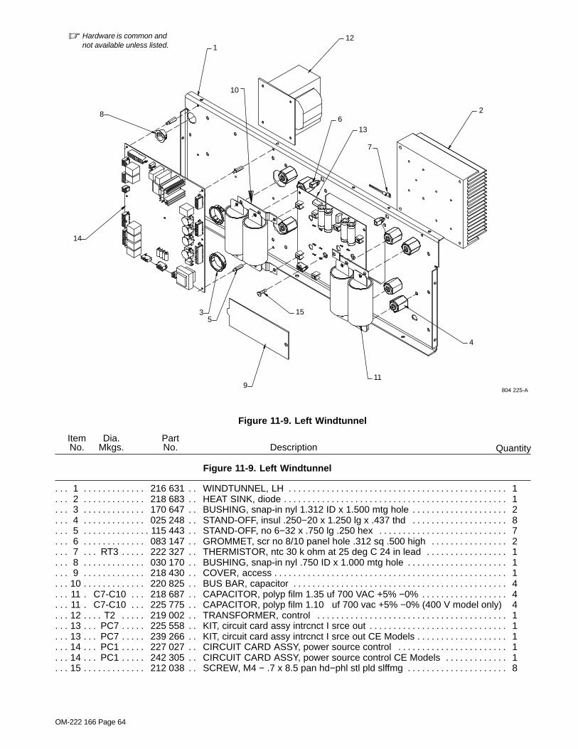
OM-222 166 Page 64
� Hardware is common andnot available unless listed.
Figure 11-9. Left Windtunnel
804 225-A
2
12
613
7
4
11
15
9
35
14
8
1
10
QuantityDescriptionPartNo.
Dia.Mkgs.
ItemNo.
Figure 11-9. Left Windtunnel
1 216 631 WINDTUNNEL, LH 1. . . . . . . . . . . . . . . . . . . . . . . . . . . . . . . . . . . . . . . . . . . . . . . . . . . . . . . . . . . . . . . . 2 218 683 HEAT SINK, diode 1. . . . . . . . . . . . . . . . . . . . . . . . . . . . . . . . . . . . . . . . . . . . . . . . . . . . . . . . . . . . . . . . . 3 170 647 BUSHING, snap-in nyl 1.312 ID x 1.500 mtg hole 2. . . . . . . . . . . . . . . . . . . . . . . . . . . . . . . . . . . . . . 4 025 248 STAND-OFF, insul .250−20 x 1.250 lg x .437 thd 8. . . . . . . . . . . . . . . . . . . . . . . . . . . . . . . . . . . . . . 5 115 443 STAND-OFF, no 6−32 x .750 lg .250 hex 7. . . . . . . . . . . . . . . . . . . . . . . . . . . . . . . . . . . . . . . . . . . . . . 6 083 147 GROMMET, scr no 8/10 panel hole .312 sq .500 high 2. . . . . . . . . . . . . . . . . . . . . . . . . . . . . . . . . . 7 RT3 222 327 THERMISTOR, ntc 30 k ohm at 25 deg C 24 in lead 1. . . . . . . . . . . . . . . . . . . . . . . . . . . . . . 8 030 170 BUSHING, snap-in nyl .750 ID x 1.000 mtg hole 1. . . . . . . . . . . . . . . . . . . . . . . . . . . . . . . . . . . . . . . 9 218 430 COVER, access 1. . . . . . . . . . . . . . . . . . . . . . . . . . . . . . . . . . . . . . . . . . . . . . . . . . . . . . . . . . . . . . . . . . .
10 220 825 BUS BAR, capacitor 4. . . . . . . . . . . . . . . . . . . . . . . . . . . . . . . . . . . . . . . . . . . . . . . . . . . . . . . . . . . . . . . 11 C7-C10 218 687 CAPACITOR, polyp film 1.35 uf 700 VAC +5% −0% 4. . . . . . . . . . . . . . . . . . . . . . . . . . . 11 C7-C10 225 775 CAPACITOR, polyp film 1.10 uf 700 vac +5% −0% (400 V model only) 4. . . . . . . . . 12 T2 219 002 TRANSFORMER, control 1. . . . . . . . . . . . . . . . . . . . . . . . . . . . . . . . . . . . . . . . . . . . . . . . . . . . . . 13 PC7 225 558 KIT, circuit card assy intrcnct I srce out 1. . . . . . . . . . . . . . . . . . . . . . . . . . . . . . . . . . . . . . . . . . 13 PC7 239 266 KIT, circuit card assy intrcnct I srce out CE Models 1. . . . . . . . . . . . . . . . . . . . . . . . . . . . . . . . 14 PC1 227 027 CIRCUIT CARD ASSY, power source control 1. . . . . . . . . . . . . . . . . . . . . . . . . . . . . . . . . . . . 14 PC1 242 305 CIRCUIT CARD ASSY, power source control CE Models 1. . . . . . . . . . . . . . . . . . . . . . . . . . 15 212 038 SCREW, M4 − .7 x 8.5 pan hd−phl stl pld slffmg 8. . . . . . . . . . . . . . . . . . . . . . . . . . . . . . . . . . . . . . .

OM-222 166 Page 65
QuantityDescriptionPartNo.
Dia.Mkgs.
ItemNo.
Figure 11-9. Left Windtunnel (Continued)
PLG16,. . . . . . . 121,122 131 054 HOUSING RCPT+SKTS, (service kit) 3. . . . . . . . . . . . . . . . . . . . . . . . . . . . . . . . . . . PLG19,. . . . . . .
120 115 094 HOUSING PLUG+SKTS, (service kit) 2. . . . . . . . . . . . . . . . . . . . . . . . . . . . . . . . . . . . . . PLG15,. . . . . . .
118 115 093 HOUSING PLUG+SKTS, (service kit) 2. . . . . . . . . . . . . . . . . . . . . . . . . . . . . . . . . . . . . . PLG77,. . . . . . .
119 115 092 HOUSING PLUG+SKTS, (service kit) 2. . . . . . . . . . . . . . . . . . . . . . . . . . . . . . . . . . . . . . PLG17 115 091 HOUSING PLUG+SKTS, (service kit) 1. . . . . . . . . . . . . . . . . . . . . . . . . . . . . . . . . . . . . . . . . . . . PLG18,. . . . . . .
116 131 056 HOUSING RCPT+SKTS, (service kit) 2. . . . . . . . . . . . . . . . . . . . . . . . . . . . . . . . . . . . . PLG13,. . . . . . .
113 162 382 HOUSING PLUG+SKTS, (service kit) 2. . . . . . . . . . . . . . . . . . . . . . . . . . . . . . . . . . . . . PLG14 130 203 HOUSING PLUG+SKTS, (service kit) 1. . . . . . . . . . . . . . . . . . . . . . . . . . . . . . . . . . . . . . . . . . .
To maintain the factory original performance of your equipment, use only Manufacturer’s SuggestedReplacement Parts. Model and serial number required when ordering parts from your local distributor.

OM-222 166 Page 66
� Hardware is common andnot available unless listed.
Figure 11-10. Hermaphroditic Blank Plug Assy
804 300-A
1
2
3
4
5
3
4
6
7
8
1
9
QuantityDescriptionPartNo.
Dia.Mkgs.
ItemNo.
Figure 11-10. Hermaphroditic Blank Plug Assy 224 260
1 221 440 O-RING, .737 ID x .103 CS 2. . . . . . . . . . . . . . . . . . . . . . . . . . . . . . . . . . . . . . . . . . . . . . . . . . . . . . . . . 2 221 443 SOCKET ASSY, radsok 14 mm cable end 1. . . . . . . . . . . . . . . . . . . . . . . . . . . . . . . . . . . . . . . . . . . . 3 221 099 CLAMP, strain relief 2. . . . . . . . . . . . . . . . . . . . . . . . . . . . . . . . . . . . . . . . . . . . . . . . . . . . . . . . . . . . . . . . 4 136 343 SCREW, K50 x 20 pan hd-phl stl pld pt 2. . . . . . . . . . . . . . . . . . . . . . . . . . . . . . . . . . . . . . . . . . . . . . . 5 224 261 CAP, plug assy 1. . . . . . . . . . . . . . . . . . . . . . . . . . . . . . . . . . . . . . . . . . . . . . . . . . . . . . . . . . . . . . . . . . . . 6 221 438 COLLAR, coupling 1. . . . . . . . . . . . . . . . . . . . . . . . . . . . . . . . . . . . . . . . . . . . . . . . . . . . . . . . . . . . . . . . . 7 221 437 RETAINER, contact 1. . . . . . . . . . . . . . . . . . . . . . . . . . . . . . . . . . . . . . . . . . . . . . . . . . . . . . . . . . . . . . . 8 221 442 PIN, radsok 14 mm cable end 1. . . . . . . . . . . . . . . . . . . . . . . . . . . . . . . . . . . . . . . . . . . . . . . . . . . . . . . 9 225 919 SHELL ASSY, connector - protective plug 1. . . . . . . . . . . . . . . . . . . . . . . . . . . . . . . . . . . . . . . . . . . .
To maintain the factory original performance of your equipment, use only Manufacturer’s SuggestedReplacement Parts. Model and serial number required when ordering parts from your local distributor.

OM-222 166 Page 67
804 324-A
1
23
4
567
8
Figure 11-11. Air−Cooled Output Extension Cables
DescriptionPartNo.
Dia.Mkgs.
ItemNo.
Figure 11-11. Air−Cooled Output Extension Cables 195 404, 195 405, And 300 362
Quantity
1 225 918 SHELL ASSY, connector − air cooled 1. . . . . . . . . . . . . . . . . . . . . . . . . . . . . . . . . . . . . . . . . . . . . . . . 2 221 438 Collar, coupling 1. . . . . . . . . . . . . . . . . . . . . . . . . . . . . . . . . . . . . . . . . . . . . . . . . . . . . . . . . . . . . . . . . . . 3 221 099 Clamp, strain relief 2. . . . . . . . . . . . . . . . . . . . . . . . . . . . . . . . . . . . . . . . . . . . . . . . . . . . . . . . . . . . . . . . 4 136 343 SCREW, k50x 20 pan hd−phl stl pld pt thread forming 2. . . . . . . . . . . . . . . . . . . . . . . . . . . . . . . . . . 5 225 968 SHELL, connector cable female with seal 2. . . . . . . . . . . . . . . . . . . . . . . . . . . . . . . . . . . . . . . . . . . . 6 224 259 CLAMP, strain relief socket 4. . . . . . . . . . . . . . . . . . . . . . . . . . . . . . . . . . . . . . . . . . . . . . . . . . . . . . . . . 7 228 296 SCREW, ka35x10 pan hd−phl sst pln pt thread forming 4. . . . . . . . . . . . . . . . . . . . . . . . . . . . . . . . . 8 197 635 LABEL, warning flexible induction cords 2. . . . . . . . . . . . . . . . . . . . . . . . . . . . . . . . . . . . . . . . . . . . . .
To maintain the factory original performance of your equipment, use only Manufacturer’s SuggestedReplacement Parts. Model and serial number required when ordering parts from your local distributor.
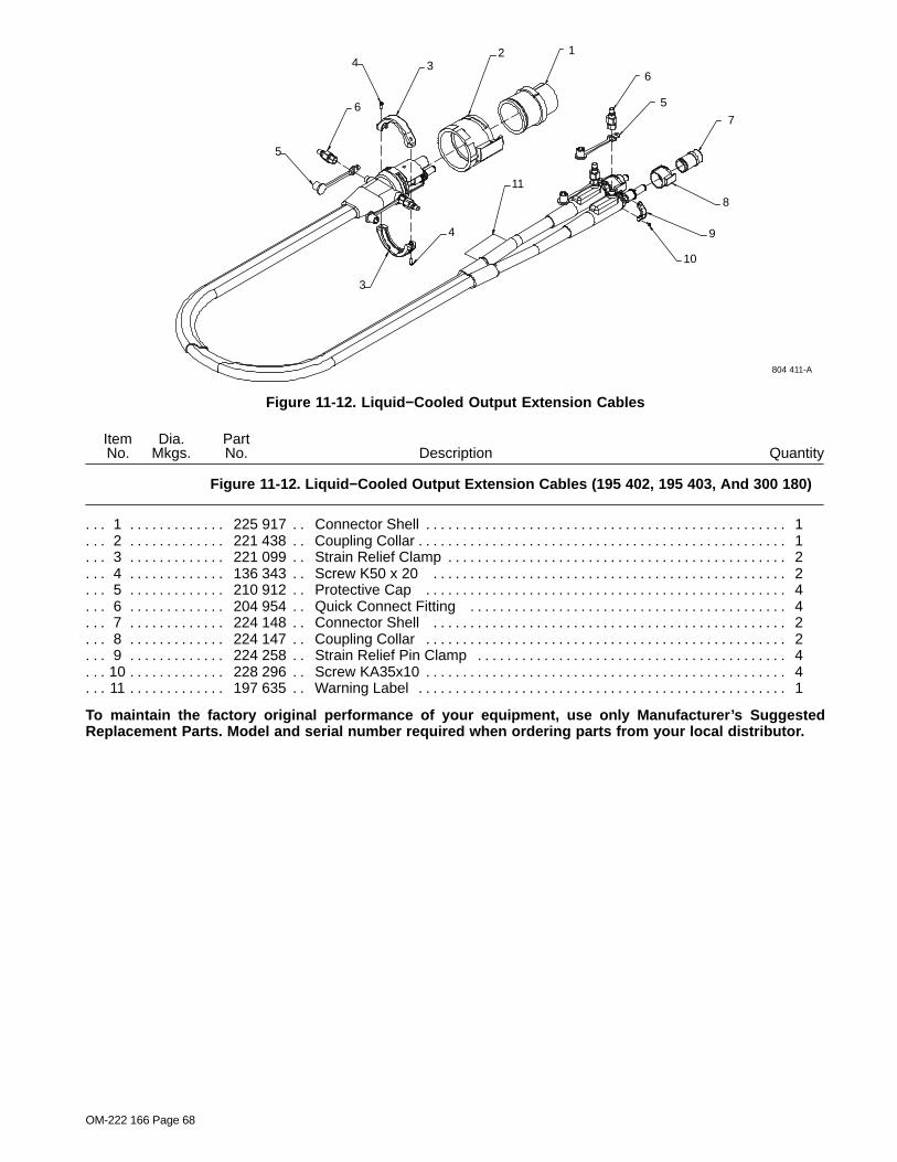
OM-222 166 Page 68
1
6
5
7
9
10
8
11
234
6
5
4
3
804 411-A
Figure 11-12. Liquid−Cooled Output Extension Cables
DescriptionPartNo.
Dia.Mkgs.
ItemNo.
Figure 11-12. Liquid−Cooled Output Extension Cables (195 402, 195 403, And 300 180)
Quantity
1 225 917 Connector Shell 1. . . . . . . . . . . . . . . . . . . . . . . . . . . . . . . . . . . . . . . . . . . . . . . . . . . . . . . . . . . . . . . . . . . 2 221 438 Coupling Collar 1. . . . . . . . . . . . . . . . . . . . . . . . . . . . . . . . . . . . . . . . . . . . . . . . . . . . . . . . . . . . . . . . . . . . 3 221 099 Strain Relief Clamp 2. . . . . . . . . . . . . . . . . . . . . . . . . . . . . . . . . . . . . . . . . . . . . . . . . . . . . . . . . . . . . . . . 4 136 343 Screw K50 x 20 2. . . . . . . . . . . . . . . . . . . . . . . . . . . . . . . . . . . . . . . . . . . . . . . . . . . . . . . . . . . . . . . . . . 5 210 912 Protective Cap 4. . . . . . . . . . . . . . . . . . . . . . . . . . . . . . . . . . . . . . . . . . . . . . . . . . . . . . . . . . . . . . . . . . . 6 204 954 Quick Connect Fitting 4. . . . . . . . . . . . . . . . . . . . . . . . . . . . . . . . . . . . . . . . . . . . . . . . . . . . . . . . . . . . . 7 224 148 Connector Shell 2. . . . . . . . . . . . . . . . . . . . . . . . . . . . . . . . . . . . . . . . . . . . . . . . . . . . . . . . . . . . . . . . . . 8 224 147 Coupling Collar 2. . . . . . . . . . . . . . . . . . . . . . . . . . . . . . . . . . . . . . . . . . . . . . . . . . . . . . . . . . . . . . . . . . . 9 224 258 Strain Relief Pin Clamp 4. . . . . . . . . . . . . . . . . . . . . . . . . . . . . . . . . . . . . . . . . . . . . . . . . . . . . . . . . . . .
10 228 296 Screw KA35x10 4. . . . . . . . . . . . . . . . . . . . . . . . . . . . . . . . . . . . . . . . . . . . . . . . . . . . . . . . . . . . . . . . . . . 11 197 635 Warning Label 1. . . . . . . . . . . . . . . . . . . . . . . . . . . . . . . . . . . . . . . . . . . . . . . . . . . . . . . . . . . . . . . . . . . .
To maintain the factory original performance of your equipment, use only Manufacturer’s SuggestedReplacement Parts. Model and serial number required when ordering parts from your local distributor.

OM-222 166 Page 69
23
1
4
5
6
6
804 404-A
Figure 11-13. Heating Cables
DescriptionPartNo.
Dia.Mkgs.
ItemNo.
Figure 11-13. Heating Cables (300 045, 300 046, 300 047, And 400 049)
Quantity
1 225 968 Connector Shell 2. . . . . . . . . . . . . . . . . . . . . . . . . . . . . . . . . . . . . . . . . . . . . . . . . . . . . . . . . . . . . . . . . . 2 204 954 Plastic Fitting 2. . . . . . . . . . . . . . . . . . . . . . . . . . . . . . . . . . . . . . . . . . . . . . . . . . . . . . . . . . . . . . . . . . . . . 3 210 912 Protective Cap 2. . . . . . . . . . . . . . . . . . . . . . . . . . . . . . . . . . . . . . . . . . . . . . . . . . . . . . . . . . . . . . . . . . . . 4 224 259 Strain Relief Clamp 4. . . . . . . . . . . . . . . . . . . . . . . . . . . . . . . . . . . . . . . . . . . . . . . . . . . . . . . . . . . . . . . 5 228 296 Screw, KA35x10 4. . . . . . . . . . . . . . . . . . . . . . . . . . . . . . . . . . . . . . . . . . . . . . . . . . . . . . . . . . . . . . . . . . 6 197 635 Warning Label 2. . . . . . . . . . . . . . . . . . . . . . . . . . . . . . . . . . . . . . . . . . . . . . . . . . . . . . . . . . . . . . . . . . . .
To maintain the factory original performance of your equipment, use only Manufacturer’s SuggestedReplacement Parts. Model and serial number required when ordering parts from your local distributor.

OM-222 166 Page 70
201 432-G
1
Figure 11-14. Quick Connect To Quick Connect Hose
DescriptionPartNo.
Dia.Mkgs.
ItemNo.
Figure 11-14. Quick Connect To Quick Connect Hose (204 877)
Quantity
1 204955 Ftg, Plstc Coupler Qdisc X 1/4 Npt Female 2. . . . . . . . . . . . . . . . . . . . . . . . . . . . . . . . . . . . . . . . . . . .
To maintain the factory original performance of your equipment, use only Manufacturer’s SuggestedReplacement Parts. Model and serial number required when ordering parts from your local distributor.

Warranty Questions?
Call1-800-4-A-MILLERfor your localMiller distributor.
miller_warr 2009−01
Your distributor also givesyou ...
ServiceYou always get the fast,reliable response youneed. Most replacementparts can be in yourhands in 24 hours.
SupportNeed fast answers to thetough welding questions?Contact your distributor.The expertise of thedistributor and Miller isthere to help you, everystep of the way.
Effective January 1, 2009(Equipment with a serial number preface of LK or newer)This limited warranty supersedes all previous Miller warranties and is exclusive with no other
guarantees or warranties expressed or implied.LIMITED WARRANTY − Subject to the terms and conditionsbelow, Miller Electric Mfg. Co., Appleton, Wisconsin, warrants toits original retail purchaser that new Miller equipment sold afterthe effective date of this limited warranty is free of defects inmaterial and workmanship at the time it is shipped by Miller. THISWARRANTY IS EXPRESSLY IN LIEU OF ALL OTHERWARRANTIES, EXPRESS OR IMPLIED, INCLUDING THEWARRANTIES OF MERCHANTABILITY AND FITNESS.
Within the warranty periods listed below, Miller will repair orreplace any warranted parts or components that fail due to suchdefects in material or workmanship. Miller must be notified inwriting within thirty (30) days of such defect or failure, at whichtime Miller will provide instructions on the warranty claimprocedures to be followed.
Miller shall honor warranty claims on warranted equipment listedbelow in the event of such a failure within the warranty timeperiods. All warranty time periods start on the delivery date of theequipment to the original end-user purchaser, and not to exceedone year after the equipment is shipped to a North Americandistributor or eighteen months after the equipment is shipped toan International distributor.
1. 5 Years Parts — 3 Years Labor* Original main power rectifiers only to include SCRs,
diodes, and discrete rectifier modules2. 3 Years — Parts and Labor
* Transformer/Rectifier Power Sources* Plasma Arc Cutting Power Sources* Process Controllers* Semi-Automatic and Automatic Wire Feeders* Inverter Power Sources (Unless Otherwise Stated)* Water Coolant Systems (Integrated)* Intellitig* Engine Driven Welding Generators
(NOTE: Engines are warranted separately by theengine manufacturer.)
3. 1 Year — Parts and Labor Unless Specified* Motor Driven Guns (w/exception of Spoolmate
Spoolguns)* Positioners and Controllers* Automatic Motion Devices* RFCS Foot Controls* Induction Heating Power Sources, Coolers, and
ElectronicControls/Recorders
* Water Coolant Systems (Non-Integrated)* Flowgauge and Flowmeter Regulators (No Labor)* HF Units* Grids* Spot Welders* Load Banks* Fume Extractors* Arc Stud Power Sources & Arc Stud Guns* Racks* Running Gear/Trailers* Plasma Cutting Torches (except APT & SAF
Models)* Field Options
(NOTE: Field options are covered under True Blue®for the remaining warranty period of the product theyare installed in, or for a minimum of one year —whichever is greater.)
* Bernard-Branded Mig Guns (No Labor)* Weldcraft-Branded TIG Torches (No Labor)* Subarc Wire Drive Assemblies
4. 6 Months — Batteries
5. 90 Days — Parts* MIG Guns and Subarc (SAW) Guns
* Induction Heating Coils and Blankets, Cables, andNon-Electronic Controls
* APT & SAF Model Plasma Cutting Torches* Remote Controls* Accessory (Kits)* Replacement Parts (No labor)* Spoolmate Spoolguns* Canvas Covers
Miller’s True Blue® Limited Warranty shall not apply to:
1. Consumable components; such as contact tips,cutting nozzles, contactors, brushes, slip rings,relays or parts that fail due to normal wear.(Exception: brushes, slip rings, and relays arecovered on Bobcat, Trailblazer, and Legendmodels.)
2. Items furnished by Miller, but manufactured by others,such as engines or trade accessories. These items arecovered by the manufacturer’s warranty, if any.
3. Equipment that has been modified by any party otherthan Miller, or equipment that has been improperlyinstalled, improperly operated or misused based uponindustry standards, or equipment which has not hadreasonable and necessary maintenance, or equipmentwhich has been used for operation outside of thespecifications for the equipment.
MILLER PRODUCTS ARE INTENDED FOR PURCHASE ANDUSE BY COMMERCIAL/INDUSTRIAL USERS AND PERSONSTRAINED AND EXPERIENCED IN THE USE ANDMAINTENANCE OF WELDING EQUIPMENT.
In the event of a warranty claim covered by this warranty, theexclusive remedies shall be, at Miller’s option: (1) repair; or (2)replacement; or, where authorized in writing by Miller inappropriate cases, (3) the reasonable cost of repair orreplacement at an authorized Miller service station; or (4)payment of or credit for the purchase price (less reasonabledepreciation based upon actual use) upon return of the goods atcustomer’s risk and expense. Miller’s option of repair orreplacement will be F.O.B., Factory at Appleton, Wisconsin, orF.O.B. at a Miller authorized service facility as determined byMiller. Therefore no compensation or reimbursement fortransportation costs of any kind will be allowed.
TO THE EXTENT PERMITTED BY LAW, THE REMEDIESPROVIDED HEREIN ARE THE SOLE AND EXCLUSIVEREMEDIES. IN NO EVENT SHALL MILLER BE LIABLE FORDIRECT, INDIRECT, SPECIAL, INCIDENTAL ORCONSEQUENTIAL DAMAGES (INCLUDING LOSS OFPROFIT), WHETHER BASED ON CONTRACT, TORT OR ANYOTHER LEGAL THEORY.
ANY EXPRESS WARRANTY NOT PROVIDED HEREIN ANDANY IMPLIED WARRANTY, GUARANTY ORREPRESENTATION AS TO PERFORMANCE, AND ANYREMEDY FOR BREACH OF CONTRACT TORT OR ANYOTHER LEGAL THEORY WHICH, BUT FOR THISPROVISION, MIGHT ARISE BY IMPLICATION, OPERATIONOF LAW, CUSTOM OF TRADE OR COURSE OF DEALING,INCLUDING ANY IMPLIED WARRANTY OFMERCHANTABILITY OR FITNESS FOR PARTICULARPURPOSE, WITH RESPECT TO ANY AND ALL EQUIPMENTFURNISHED BY MILLER IS EXCLUDED AND DISCLAIMEDBY MILLER.
Some states in the U.S.A. do not allow limitations of how long animplied warranty lasts, or the exclusion of incidental, indirect,special or consequential damages, so the above limitation orexclusion may not apply to you. This warranty provides specificlegal rights, and other rights may be available, but may vary fromstate to state.
In Canada, legislation in some provinces provides for certainadditional warranties or remedies other than as stated herein,and to the extent that they may not be waived, the limitations andexclusions set out above may not apply. This Limited Warrantyprovides specific legal rights, and other rights may be available,but may vary from province to province.

ORIGINAL INSTRUCTIONS − PRINTED IN USA © 2009 Miller Electric Mfg. Co. 2009−01
Miller Electric Mfg. Co.An Illinois Tool Works Company1635 West Spencer StreetAppleton, WI 54914 USA
International Headquarters−USAUSA Phone: 920-735-4505 Auto-AttendedUSA & Canada FAX: 920-735-4134International FAX: 920-735-4125
For International Locations Visitwww.MillerWelds.com
Model Name Serial/Style Number
Purchase Date (Date which equipment was delivered to original customer.)
Distributor
Address
City
State Zip
Please complete and retain with your personal records.
Always provide Model Name and Serial/Style Number.
Contact a DISTRIBUTOR or SERVICE AGENCY near you.
Welding Supplies and Consumables
Options and Accessories
Personal Safety Equipment
Service and Repair
Replacement Parts
Training (Schools, Videos, Books)
Technical Manuals (Servicing Informationand Parts)
Circuit Diagrams
Welding Process Handbooks
Contact the Delivering Carrier to:
For Service
Owner’s Record
File a claim for loss or damage duringshipment.
For assistance in filing or settling claims, contactyour distributor and/or equipment manufacturer’sTransportation Department.
Contact your Distributor for:
To locate a Distributor or Service Agency visitwww.millerwelds.com or call 1-800-4-A-Miller