Progressive collapse of cold-formed steel framed...
14
Progressive collapse of cold-formed steel framed structures Sang-Wook Bae, Roger A. LaBoube , Abdeldjelil Belarbi, Ashraf Ayoub Department of Civil, Architectural, and Environmental Engineering, University of Missouri-Rolla, 1870 Miner Circle, Rolla, MO 65409-0030, USA article info Available online 22 April 2008 Keywords: Cold-formed steel Joists Progressive failure Collapse Studs abstract This study investigated the possibility of progressive collapse of a cold-formed steel framed structure. Five different analysis cases were considered, exterior wall column removal specified in General Services Administration (GSA) guidelines and Department of Defense (DoD) guidelines, corner wall column removal specified in GSA and DoD guidelines, and analysis by Successive Removal. The results showed that the removal of corner wall columns appeared to cause progressive collapse of a portion of the second and third floor of the end bay directly associated with the column removal, and not the entire building. & 2008 Published by Elsevier Ltd. 1. Introduction 1.1. Background Progressive collapse has attracted the attention of engineers since the structural failure of a 22-story apartment building at Ronan Point, London, UK, in 1968. The terminology of progressive collapse is defined as ‘‘the spread of an initial local failure from element to element, eventually resulting in the collapse of an entire structure or a disproportionately large part of it’’ [1]. Since progressive collapse is usually disproportionate to initial damage, even small events can cause progressive collapse. A recent history of progressive collapse events can be found elsewhere [2,3]. For many years steel has been shaping our built environment. Today steel remains one of the strongest, most durable, and economically manufactured materials. In recent years cold- formed steel has emerged as a viable material for framing of commercial and residential single and multistory structures. Cold- formed steel’s benefits are many, to cite few: lightweight, ease of handling, dimensional stability, cost effectiveness, high quality alternative to traditional wood framing, not susceptible to insect damage and rotting, in addition to being renewable. The overall recycling rate for steel products is 66%—the highest for any material. In fact cold-formed steel is a logical choice to address the following thematic areas of technological need: quality, durability, environmental performance, and affordability. For cold-formed steel structural design, North American Specification for the Design of Cold-Formed Steel Structural Members [4] is used to determine the required size of the structural members; however, this specification is silent about progressive collapse design. Currently, some codes and guidelines have attempted to address the issues of this type of collapse. Section 1.4 of ASCE 7- 05 Minimum Design Loads for Buildings and Other Structures [1] gives qualitative guidelines, but are not quantitative. In addition, the commentary suggests several different design concepts to provide structural integrity through providing sufficient continu- ity, redundancy, and/or ductility in the structural members of a building. General Service Administration (GSA) [5] and Depart- ment of Defense (DoD) [6] have developed guidelines to address the vulnerability of a building to progressive collapse. In these guidelines, there are two progressive collapse mitigation design approaches: the direct design approach and indirect design approach. The Direct Design approach addressed progressive collapse by applying structural analysis design principles. Indirect design addresses progressive collapse mitigation through pre- scriptive detailing. The DoD guidelines stipulate either the tie force method (indirect design approach) and/or the alternate path method (direct design approach) for progressive collapse design. To optimize the design requirements for both the alternative load path (ALP) method and the tie force method, it is imperative that performance criteria should be developed and established to reflect the synergism inherent in the components of the cold- formed steel framed system. However, research regarding cold- formed steel structures has focused primarily on the behavior of individual members, such as beams, columns, and connections. Limited research has been performed pertaining to the behavior of a cold-formed steel structural system. Furthermore, the most prevalent cold-formed steel framing approach is to employ in-line framing, which provides a direct load path from the upper-floor wall stud to the lower-floor wall stud or from the joist to the load bearing wall stud. As a result, an alternative load transfer system will need to be introduced in the framing assembly if a wall stud ARTICLE IN PRESS Contents lists available at ScienceDirect journal homepage: www.elsevier.com/locate/tws Thin-Walled Structures 0263-8231/$ - see front matter & 2008 Published by Elsevier Ltd. doi:10.1016/j.tws.2008.01.041 Corresponding author. Tel.: +1573 3414481; fax: +1573 3414729. E-mail address: [email protected] (R.A. LaBoube). Thin-Walled Structures 46 (2008) 706– 719
Transcript of Progressive collapse of cold-formed steel framed...

ARTICLE IN PRESS
Thin-Walled Structures 46 (2008) 706– 719
Contents lists available at ScienceDirect
Thin-Walled Structures
0263-82
doi:10.1
� Corr
E-m
journal homepage: www.elsevier.com/locate/tws
Progressive collapse of cold-formed steel framed structures
Sang-Wook Bae, Roger A. LaBoube �, Abdeldjelil Belarbi, Ashraf Ayoub
Department of Civil, Architectural, and Environmental Engineering, University of Missouri-Rolla, 1870 Miner Circle, Rolla, MO 65409-0030, USA
a r t i c l e i n f o
Available online 22 April 2008
Keywords:
Cold-formed steel
Joists
Progressive failure
Collapse
Studs
31/$ - see front matter & 2008 Published by
016/j.tws.2008.01.041
esponding author. Tel.: +1573 3414481; fax:
ail address: [email protected] (R.A. LaBoube)
a b s t r a c t
This study investigated the possibility of progressive collapse of a cold-formed steel framed structure.
Five different analysis cases were considered, exterior wall column removal specified in General
Services Administration (GSA) guidelines and Department of Defense (DoD) guidelines, corner wall
column removal specified in GSA and DoD guidelines, and analysis by Successive Removal. The results
showed that the removal of corner wall columns appeared to cause progressive collapse of a portion of
the second and third floor of the end bay directly associated with the column removal, and not the
entire building.
& 2008 Published by Elsevier Ltd.
1. Introduction
1.1. Background
Progressive collapse has attracted the attention of engineerssince the structural failure of a 22-story apartment buildingat Ronan Point, London, UK, in 1968. The terminology ofprogressive collapse is defined as ‘‘the spread of an initial localfailure from element to element, eventually resulting in thecollapse of an entire structure or a disproportionately large part ofit’’ [1]. Since progressive collapse is usually disproportionate toinitial damage, even small events can cause progressive collapse.A recent history of progressive collapse events can be foundelsewhere [2,3].
For many years steel has been shaping our built environment.Today steel remains one of the strongest, most durable, andeconomically manufactured materials. In recent years cold-formed steel has emerged as a viable material for framing ofcommercial and residential single and multistory structures. Cold-formed steel’s benefits are many, to cite few: lightweight, ease ofhandling, dimensional stability, cost effectiveness, high qualityalternative to traditional wood framing, not susceptible to insectdamage and rotting, in addition to being renewable. The overallrecycling rate for steel products is 66%—the highest for anymaterial. In fact cold-formed steel is a logical choice to address thefollowing thematic areas of technological need: quality, durability,environmental performance, and affordability. For cold-formedsteel structural design, North American Specification for the Design
of Cold-Formed Steel Structural Members [4] is used to determine
Elsevier Ltd.
+1573 3414729.
.
the required size of the structural members; however, thisspecification is silent about progressive collapse design.
Currently, some codes and guidelines have attempted toaddress the issues of this type of collapse. Section 1.4 of ASCE 7-
05 Minimum Design Loads for Buildings and Other Structures [1]gives qualitative guidelines, but are not quantitative. In addition,the commentary suggests several different design concepts toprovide structural integrity through providing sufficient continu-ity, redundancy, and/or ductility in the structural members of abuilding. General Service Administration (GSA) [5] and Depart-ment of Defense (DoD) [6] have developed guidelines to addressthe vulnerability of a building to progressive collapse. In theseguidelines, there are two progressive collapse mitigation designapproaches: the direct design approach and indirect designapproach. The Direct Design approach addressed progressivecollapse by applying structural analysis design principles. Indirectdesign addresses progressive collapse mitigation through pre-scriptive detailing. The DoD guidelines stipulate either the tieforce method (indirect design approach) and/or the alternate pathmethod (direct design approach) for progressive collapse design.
To optimize the design requirements for both the alternativeload path (ALP) method and the tie force method, it is imperativethat performance criteria should be developed and established toreflect the synergism inherent in the components of the cold-formed steel framed system. However, research regarding cold-formed steel structures has focused primarily on the behavior ofindividual members, such as beams, columns, and connections.Limited research has been performed pertaining to the behavior ofa cold-formed steel structural system. Furthermore, the mostprevalent cold-formed steel framing approach is to employ in-lineframing, which provides a direct load path from the upper-floorwall stud to the lower-floor wall stud or from the joist to the loadbearing wall stud. As a result, an alternative load transfer systemwill need to be introduced in the framing assembly if a wall stud

ARTICLE IN PRESS
S.-W. Bae et al. / Thin-Walled Structures 46 (2008) 706–719 707
was removed by a catastrophic event. It is, therefore, necessary toconduct this research study in order to investigate the overallsystem behavior of cold-formed steel framing structures and toevaluate their potential for progressive collapse.
1.2. Objectives and scope
The main objectives of this study are: (1) to investigate theperformance of a cold-formed steel structure with one or morestructural elements experiencing a sudden collapse, (2) todetermine the ALPs after the sudden removal of stud columns,and (3) to determine the possibility of progressive collapse. Theload that causes progressive collapse of a structure can be dividedinto two different loads: (1) primary load and (2) secondary load.The primary load is the load that causes the structural element tofail. External abnormal loads, such as blast pressure due toexplosion and vehicular impact, are the examples of the primaryload. The secondary loads are the loads that are generated due tothe change of structural geometry caused by sudden collapseof an element. It can be realistically assumed that the timelapse between primary loading and secondary loading may bevery short and thus the two loads cannot be separated. However,in the situation where the definition of primary loading is notclearly understood (for example, it is almost impossible todefine the scenario of explosion due to terrorist attacks orvehicular impacts), it may be best as a first step to analyze thestructure under two separate loading conditions (primary andsecondary loadings).
1.3. Research significance
Studies regarding the progressive collapse of cold-formed steelstructures do not exist in the literature. This might be due to thefact that cold-formed steel structures have been assumed not tobe susceptible to that kind of failure or collapse owing to theirinherent redundancy. However, because cold-formed steel isgaining widespread use for mid-rise structural systems, includingbut not limited in army barracks, the possibility of progressivecollapse of cold-formed steel structures has become an importantissue. This study will serve as a first attempt to address thisresearch need.
2. Current codes and guidelines
2.1. SEI/ASCE 7-05 minimum design loads for buildings and other
structures [1]
This specification does not prescribe specific measures tomitigate progressive collapse, but presents a philosophy ofensuring structural integrity. Section 1.4 of SEI/ASCE 7-05stipulates that ‘‘Buildings and other structures shall be designedto sustain local damage with the structural systems as a wholeremaining stable and not being damaged to an extent dispropor-tionate to the original local damage. This shall be achievedthrough an arrangement of the structural elements that providesstability to the entire structural system by transferring loads fromany locally damaged region to adjacent regions capable ofresisting those loads without collapse. This shall be accomplishedby providing sufficient continuity, redundancy, or energy-dissi-pating capacity (ductility), or a combination thereof, in themembers of the structure.’’
2.2. GSA progressive collapse analysis and design guidelines for new
federal office buildings and major modernization projects [6]
GSA guidelines introduce a protocol for determining if abuilding is exempt from progressive collapse considerations. Thetype and size of the buildings are the basis for the exemptionprocess while the level of threat is not directly related to theexemption process. According to the guidelines, typical non-exempt buildings constructed with steel or concrete shouldappear to tolerate removal of one exterior column or one 9.1 m(30 ft) length of exterior load bearing wall at ground levelwithout collapse.
2.3. UFC 4-023-03 design of buildings to resist progressive collapse
by US DoD [5]
UFC 4-023-03 (referred to as DoD guidelines hereafter) presenttwo design methods for assessing the structural response toprogressive collapse. The first method for progressive collapsedesign employs Tie Forces Method, which is based on a catenaryaction of the structural elements. The second method employs theALP method, in which the structural mode is flexural, as thebuilding must bridge over a removed element.
2.4. Difference between GSA and DoD guidelines
The GSA and DoD guidelines have similarities in many aspects;however, there are key differences between them. A significantdifference is that the DoD guidelines apply the ALP method ateach floor level in a multistory building, whereas the GSAguidelines require the member removal scenario to be appliedonly at the ground floor level. Another key difference is that GSAadapted the use of a member demand-to-capacity ratio (DCR)analysis from an analysis procedure that has been prescribed bythe research studies reported by FEMA [7,8] for the seismicrehabilitation of existing buildings. Other differences exist, suchas in how material strengths are defined.
3. Recent studies on progressive collapse
The current GSA and DoD guidelines are summarized herein toprovide a clear understanding of the guidelines [2,3,9,10]. Schmidt[9] presented a summary of the methods available to define anexternal terrorist bomb threat and estimate structural designloads and element responses using simple dynamic systemmodels and principles. Nair [3] in an article entitled ‘‘ProgressiveCollapse Basics’’ provided engineers with some basic informationabout progressive collapse such as the definition of progressivecollapse, available codes and standards, historical examples ofprogressive collapse of buildings. Marjanishvili [10] presentedfour sophisticated analysis procedures for evaluating the pro-gressive collapse hazard: linear-elastic static, nonlinear static,linear-elastic dynamic, and nonlinear dynamic. The authordiscussed the advantages and disadvantages of each method andconcluded that the most effective analysis procedure for progres-sive collapse evaluation incorporates the advantageous parts of allfour procedures by systematically applying increasingly compre-hensive analysis procedures to confirm that the possibility ofprogressive collapse is high. AISC [2] provides the latest informa-tion and guidance available for commercial and industrialbuildings subjected to extraordinary loads and responses. Thedocument also presents background and definitions for explosiveloads and progressive collapse, general principles of blastloads and response prediction, recommendations for structures

ARTICLE IN PRESS
S.-W. Bae et al. / Thin-Walled Structures 46 (2008) 706–719708
designed to resist blast and mitigate progressive collapse, recentguidelines and Federal and DoD requirements, and some informa-tion on ongoing research.
Finite element (FE) models were developed and proposed inrecent years to predict the possibility of progressive collapse[11,12]. Along with the lack of the implementation data of theguidelines, the FE models also needed to be investigated in termsof their accuracy and efficiency. Kaewkulchai and Williamson [11]developed an analysis software to simulate the behavior ofstructural frames during a collapse event. The software consideredthe effect of both geometric and material nonlinearity and itincorporated a damage index to account for strength and stiffnessdegradation. Khandelwal and El-Tawil [12] used a detailed FEsimulation to investigate the large deformation behavior ofseismically designed beam-column sub-assemblies. The FE modelemployed a micro-mechanical fracture model for steel and used itto understand the role of a number of parameters that influencethe formation of catenary action in steel moment resisting frameconnections.
Limited number of experimental studies on progressivecollapse are available to date [13–15]. In addition, the mainpurpose of these studies was only to investigate the resistance ofthe structures against blast loads, which could be the main loadcausing progressive collapse. Woodson and Baylot [13] testedtwo-story, quarter-scale reinforced concrete (RC) structures toinvestigate the RC building with in-fill walls to blast effects.Experiments were conducted on five models, allowing a variationin the explosives standoff and the in-fill wall configuration. Blastloads were applied using 7.09 kg (15.625 lb) of C-4 at a stand offdistance of 1.5 m (5 ft) and 0.9 m (3.5 ft). As a result, it was foundthat the presence of in-fill walls has a significant effect on theimpulse of the load applied to a column, i.e., the in-fill walls couldreduce the blast effects on the slab floor. Astaneh-Asl [14]conducted an experimental study to investigate the viability of asteel cable-based system to prevent progressive collapse ofbuildings. He tested a total of 10 full-scale one-story buildings.The test buildings were 18.3 m (60 ft)�6.1 m (20 ft) typical onestory steel structure with steel deck and concrete floor and wideflange beams and columns. One side of the floor in the testbuildings had steel cables within the floor representing newconstruction and the other side had cables placed on the outsideas a measure of retrofit of existing buildings. One column of thetest column assembly was removed to investigate the effects ofthe cable system. The tests and corresponding analyses indicated
Fig. 1. Plan view of the first floor of the army barracks: (a) area used in the FEA model fo
that the cable-based system could economically and efficientlyprevent progressive collapse of the floor in the event of a car bombattack and removal of one of the exterior columns. Malvar [15]presented an overview of a design procedure to increase thespecific local resistance (SLR) of RC columns, review of some SLRvalidation tests that have been completed and discusses therelative benefits of the ALP method and SLR method. Duringthe SLR validation tests, a full-scale building was subjected to ablast load in order to evaluate ordinary and retrofitted RCcolumns. The author concluded that both methods could beapplied efficiently, and SLR might only require increased hoopsteel reinforcement.
The possibility of the progressive collapse is largely dependenton the type of structures, materials used, and structural config-urations. Hence, the experimental results of RC structures andsteel structures may not directly be applicable to cold-formedsteel framed structures. Additionally, simplified model tests orsingle member tests can only predict the ductility and strength ofthe member considered, not the overall behavior of the structuresconsidered. Therefore, an experimental study is necessary toevaluate the possibility of progressive collapse of cold-formedsteel structures.
4. Analysis procedure
4.1. Cold-formed steel framed structure analyzed in the study
A prototype army barracks was considered in this study. Thefirst floor framing plan of the barracks is presented in Fig. 1. Thebarracks is a three-story cold-formed steel framed structure with50.3 m (165 ft)�17.1 m (56 ft) in plan, 2.9 m (9.5 ft) floor-to-floorheight, with a truss roof system. Exterior and interior load bearingwalls consist of various sizes of studs at 406 mm (16 in) on centerattached to top and bottom track sections. The structureincorporates a normal weight brick veneer. This structure wasoriginally designed to resist the dead load and live load, assummarized in Table 1, as well as 140 km/h (90 mph) wind loadand seismic load for Seismic Zone 4.
Material properties of the cold-formed steel used in thisstructure were assumed as follows: (1) All stud and joist members1.4 mm (54 mils) thickness and heavier were formed from steelcorresponding to ASTM A653 [16] with a minimum yield strengthof 345 MPa (50 ksi). (2) All 1.1 mm (45 mils) thickness and lighter
r exterior wall removal and (b) area used in the FEA model for corner wall removal.
ARTICLE IN PRESS
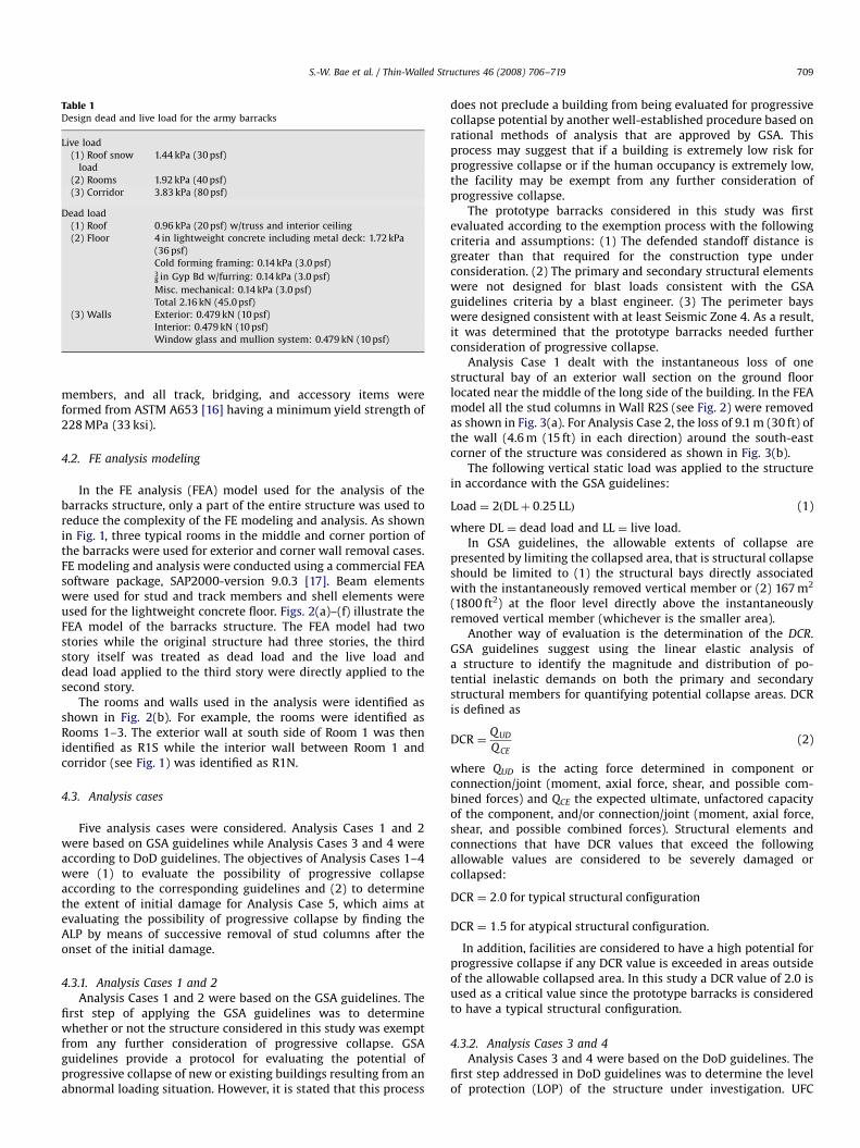
Table 1Design dead and live load for the army barracks
Live load
(1) Roof snow
load
1.44 kPa (30 psf)
(2) Rooms 1.92 kPa (40 psf)
(3) Corridor 3.83 kPa (80 psf)
Dead load
(1) Roof 0.96 kPa (20 psf) w/truss and interior ceiling
(2) Floor 4 in lightweight concrete including metal deck: 1.72 kPa
(36 psf)
Cold forming framing: 0.14 kPa (3.0 psf)38 in Gyp Bd w/furring: 0.14 kPa (3.0 psf)
Misc. mechanical: 0.14 kPa (3.0 psf)
Total 2.16 kN (45.0 psf)
(3) Walls Exterior: 0.479 kN (10 psf)
Interior: 0.479 kN (10 psf)
Window glass and mullion system: 0.479 kN (10 psf)
S.-W. Bae et al. / Thin-Walled Structures 46 (2008) 706–719 709
members, and all track, bridging, and accessory items wereformed from ASTM A653 [16] having a minimum yield strength of228 MPa (33 ksi).
4.2. FE analysis modeling
In the FE analysis (FEA) model used for the analysis of thebarracks structure, only a part of the entire structure was used toreduce the complexity of the FE modeling and analysis. As shownin Fig. 1, three typical rooms in the middle and corner portion ofthe barracks were used for exterior and corner wall removal cases.FE modeling and analysis were conducted using a commercial FEAsoftware package, SAP2000-version 9.0.3 [17]. Beam elementswere used for stud and track members and shell elements wereused for the lightweight concrete floor. Figs. 2(a)–(f) illustrate theFEA model of the barracks structure. The FEA model had twostories while the original structure had three stories, the thirdstory itself was treated as dead load and the live load anddead load applied to the third story were directly applied to thesecond story.
The rooms and walls used in the analysis were identified asshown in Fig. 2(b). For example, the rooms were identified asRooms 1–3. The exterior wall at south side of Room 1 was thenidentified as R1S while the interior wall between Room 1 andcorridor (see Fig. 1) was identified as R1N.
4.3. Analysis cases
Five analysis cases were considered. Analysis Cases 1 and 2were based on GSA guidelines while Analysis Cases 3 and 4 wereaccording to DoD guidelines. The objectives of Analysis Cases 1–4were (1) to evaluate the possibility of progressive collapseaccording to the corresponding guidelines and (2) to determinethe extent of initial damage for Analysis Case 5, which aims atevaluating the possibility of progressive collapse by finding theALP by means of successive removal of stud columns after theonset of the initial damage.
4.3.1. Analysis Cases 1 and 2
Analysis Cases 1 and 2 were based on the GSA guidelines. Thefirst step of applying the GSA guidelines was to determinewhether or not the structure considered in this study was exemptfrom any further consideration of progressive collapse. GSAguidelines provide a protocol for evaluating the potential ofprogressive collapse of new or existing buildings resulting from anabnormal loading situation. However, it is stated that this process
does not preclude a building from being evaluated for progressivecollapse potential by another well-established procedure based onrational methods of analysis that are approved by GSA. Thisprocess may suggest that if a building is extremely low risk forprogressive collapse or if the human occupancy is extremely low,the facility may be exempt from any further consideration ofprogressive collapse.
The prototype barracks considered in this study was firstevaluated according to the exemption process with the followingcriteria and assumptions: (1) The defended standoff distance isgreater than that required for the construction type underconsideration. (2) The primary and secondary structural elementswere not designed for blast loads consistent with the GSAguidelines criteria by a blast engineer. (3) The perimeter bayswere designed consistent with at least Seismic Zone 4. As a result,it was determined that the prototype barracks needed furtherconsideration of progressive collapse.
Analysis Case 1 dealt with the instantaneous loss of onestructural bay of an exterior wall section on the ground floorlocated near the middle of the long side of the building. In the FEAmodel all the stud columns in Wall R2S (see Fig. 2) were removedas shown in Fig. 3(a). For Analysis Case 2, the loss of 9.1 m (30 ft) ofthe wall (4.6 m (15 ft) in each direction) around the south-eastcorner of the structure was considered as shown in Fig. 3(b).
The following vertical static load was applied to the structurein accordance with the GSA guidelines:
Load ¼ 2ðDLþ 0:25 LLÞ (1)
where DL ¼ dead load and LL ¼ live load.In GSA guidelines, the allowable extents of collapse are
presented by limiting the collapsed area, that is structural collapseshould be limited to (1) the structural bays directly associatedwith the instantaneously removed vertical member or (2) 167 m2
(1800 ft2) at the floor level directly above the instantaneouslyremoved vertical member (whichever is the smaller area).
Another way of evaluation is the determination of the DCR.GSA guidelines suggest using the linear elastic analysis ofa structure to identify the magnitude and distribution of po-tential inelastic demands on both the primary and secondarystructural members for quantifying potential collapse areas. DCRis defined as
DCR ¼QUD
QCE(2)
where QUD is the acting force determined in component orconnection/joint (moment, axial force, shear, and possible com-bined forces) and QCE the expected ultimate, unfactored capacityof the component, and/or connection/joint (moment, axial force,shear, and possible combined forces). Structural elements andconnections that have DCR values that exceed the followingallowable values are considered to be severely damaged orcollapsed:
DCR ¼ 2:0 for typical structural configuration
DCR ¼ 1:5 for atypical structural configuration.
In addition, facilities are considered to have a high potential forprogressive collapse if any DCR value is exceeded in areas outsideof the allowable collapsed area. In this study a DCR value of 2.0 isused as a critical value since the prototype barracks is consideredto have a typical structural configuration.
4.3.2. Analysis Cases 3 and 4
Analysis Cases 3 and 4 were based on the DoD guidelines. Thefirst step addressed in DoD guidelines was to determine the levelof protection (LOP) of the structure under investigation. UFC

ARTICLE IN PRESS
Room 1 Room 2 Room 3
R1S
South
R2S
R1N R2N
R1W
R2W
R3W
R3E
(or
R3E
C)
South
7442 mm7442 mm 7442 mm
(Room 1) (Room 3) (Room 2)
2883
mm
"28
83m
m"
7442 mm"7442 mm 7442 mm"
(Room 1) (Room 3) (Room 2)
2883
mm
"28
83m
m"
24'
2883
mm
"28
83m
m
South
(Room 1)
7442 mm"
(Room 2) 7442 mm"
(Room 3)
7442 mm"
7315
mm
R3S
R3N
Fig. 2. FEA modeling of the army barracks: (a) 3-D view of FEA model, (b) identification of the walls, (c) configuration of exterior wall, R1S–R3S, (d) configuration of interior
wall, R1N–R3N, (e) configuration of interior walls, R1W–R3W (or R3EC), and (f) configuration of floor.
S.-W. Bae et al. / Thin-Walled Structures 46 (2008) 706–719710
4-010-01 (DoD [18]) requires that all new and existing buildings ofthree stories or more be designed to avoid progressive collapse.According to UFC 4-020-01 (DoD [18]), the LOP is assigned to bothnew and existing structures, which is used to define the correspond-ing level of progressive collapse design. The LOP is categorized into
four different LOPs: (1) very low LOP (VLOP), low LOP (LLOP),medium LOP (MLOP), and high LOP (HLOP). The barracks consideredin this study may be categorized into LLOP because the typical three-story wood frame army barracks is treated as LLOP based on anexample problem provided in DoD guidelines. For structures with

ARTICLE IN PRESS
Fig. 3. FEA models of Analysis Cases 1–4: (a) Analysis Case 1, (b) Analysis Case 2, (c) Analysis Case 3, and (d) Analysis Case 4.
S.-W. Bae et al. / Thin-Walled Structures 46 (2008) 706–719 711
LLOP, ALP method is not mandatory to prove the structuralresistance to the progressive collapse while horizontal and verticaltie force capacity must be satisfactory. Only if a vertical structuralmember cannot provide the required vertical tie force capacity,designers must either re-design the member or use the ALP methodto prove that the structure can bridge over the deficient verticalstructural member. The purpose of this study was, however, toevaluate the potential of progressive collapse of the barracksstructure due to the loss of column studs resulting from theabnormal loads. Therefore, in this study, the ALP method was used,although originally intended for the structures with MLOP or HLOP.
In Analysis Case 3, the removal of external load bearing wallnear the middle of the long side of the building was considered. Itwas required in the DoD guidelines that a length of wall equal totwo times the wall height but not less than the distance betweenexpansion or control joints should be removed. Therefore, all thestud columns in Wall F1-R2S were removed, as shown in Fig. 3(c).Analysis Case 4 dealt with the removal of load-bearing walls at thecorner. In this case, it was required that a length of wall equal towall height in each direction but not less than the distancebetween expansion or control joints be removed. Fig. 3(d)presents the 3-D view of FEA model of Analysis Case 4.
DoD guidelines requires that for linear and nonlinear staticanalyses of all construction types, the following amplified factoredload combination should be applied to those bays immediatelyadjacent to the removed element and at all floors above theremoved element:
Load ¼ 2:0½ð0:9 or 1:2ÞDLþ ð0:5 LL or 0:2SÞ� þ 0:2W (3)
where S is the snow load and W the wind load. For the rest of thestructure, the following load combination is applied:
Load ¼ ð0:9 or 1:2ÞDLþ ð0:5 LL or 0:2SÞ þ 0:2W (4)
In this study, only gravity load was considered. Therefore, forthe bays immediately adjacent to the removed element and at allfloors above the removed element, the load combination as shownin Eq. (5) was used. For all other areas, the load combination asshown in Eq. (6) was used:
Load ¼ 2:0½0:9 DLþ 0:5 LL� (5)
Load ¼ 0:9 DLþ 0:5 LL (6)
DoD guidelines requires that the collapse area of the floordirectly above the removed element must be less than the smallerof 70 m2 (750 ft2) or 15% of the total area of that floor. In addition,acceptability criteria for structural elements and connections areprovided. Following the LRFD approach, the design strengthprovided by a member and its connections to other members istaken as the product of the strength reduction factor f and thenominal strength Rn, and must not be less than the requiredstrength, which is the internal force created by the factored loads,
fRnXRequired strength (7)
According to the North American Specification (AISI 2001), f istaken as 0.85 for compression member, 0.9 for tension member,and 0.95 for flexural member.
4.3.3. Analysis Case 5
GSA guidelines and DoD guidelines are basically developed forthe design of new or existing buildings. If one or more structuralmember is determined to be severely damaged or if it collapsesdue to the initial damage, the damaged members must be re-designed in order to meet the requirements provided by theguidelines. However, the purpose of this study was to evaluate thepossibility of the potential for progressive collapse. Thus, the re-design process for the damaged structural members was notnecessary in this study. Instead, the damaged structural memberswere removed. The linear elastic analysis for the damagedstructure was repeatedly performed until the structure wasdetermined to be collapsed or all structural members were foundto have the resistance to the applied load.
The analysis by successive removal of stud columns wasperformed by the procedure illustrated in Fig. 4. Step 1 of theprocedure was to determine the initial damage level. The size ofthe initial damage (i.e., the length of removed wall) for both GSAguidelines and DoD guidelines is different. In fact, the determina-tion of initial damage that possibly causes the progressive collapseof a building is not a simple process, since the source of theprimary load that creates the initial damage is unlimited. Thus, inthis study, the extent of initial damage presented by the GSAguidelines and DoD guidelines was used. The choice of initialdamage between GSA guidelines and DoD guidelines was basedon the results of Analysis Cases 1–4, which is presented in detail

ARTICLE IN PRESS
STEP 1Determination of Initial Damage Level
(Selected the most critical cases among Analysis Cases 1 through 4)
STEP 3Check the Applied Force and DCR value in Each Member
If DCR value of every member is less than 2.0, go to STEP 5.Otherwise, go to STEP 4
STEP 4Remove the members of which DCR values are greater
than or equal to 2.0 from the FEA model
STEP 5Evaluate the Extent of Structural Damage According to GSA guidelines
STEP 2Perform a Linear Analysis
Fig. 4. Analysis procedure of Analysis Case 5: successive removal of damaged structural elements.
Fig. 5. Results of Analysis Case 1: (a) deformed shape of FEA model of Analysis Case 1 and (b) failed members of Analysis Case 1.
S.-W. Bae et al. / Thin-Walled Structures 46 (2008) 706–719712
in the following sections. Among the four cases, the case with themost severe damage (i.e., the extent of damage of Analysis Case 2)was selected and used for the initial damage for Analysis Case 5.
Step 2 was to perform a linear analysis. When conducting theanalysis, the following assumptions were made: (1) for cold-formed steel structural members, there was no formation ofplastic hinges and (2) the capacities of all the vertical jointconnections were assumed to be strong enough to resist the forcegenerated by linear analysis. The second assumption was verified
through the comparison of each joint connection capacity withthe applied axial load to the joints.
Step 3 was to check the DCR values of each structural memberto determine whether or not the member was severely damagedand collapsed. The member with a DCR value of 2 or greater wasremoved from the FEA model in Step 4 and Steps 1–4 wererepeated until there was no structural member of which DCR wasgreater or equal to 2. Then, the extent of damage was evaluatedaccording to GSA guidelines at Step 5.

ARTICLE IN PRESS
S.-W. Bae et al. / Thin-Walled Structures 46 (2008) 706–719 713
5. Results and discussions
5.1. Analysis Case 1
This analysis case dealt with the removal of entire stud columnsin Wall F1-R2S. Fig. 5 shows the deformed shape and the collapsedmembers. The failed members were only the track sectionsbetween the stud columns. The track sections in an in-line framingcold-formed structure are generally not designed to resist anymoment. Hence, the track sections may be assumed not to becollapsed if all the stud columns in a wall assembly are intact.However, it appeared that the track sections in Wall R2S wouldcollapse since all the stud columns in Wall F1-R2S were removed.As a result, it can be anticipated that Wall R2S would collapse, butthe entire structure would not fail by progressive collapse. To avoidthis type of collapse, the track sections used in the South exteriorwall must be designed as structural members like header sections.
5.2. Analysis Case 2
In this analysis case, the stud columns at the corner of Southand East side were removed. The deformed shape of the structureis presented in Fig. 6(a). Like Analysis Case 1, the deformation in
Fig. 6. Results of Analysis Case 2: (a) deformed shape of FEA mode
the floors directly above the removed walls was significantlylarger when compared to the other areas. The locations of thefailed members are shown in Fig. 6(b). As shown in Fig. 6(b), someof the track sections in Walls R1S and R2S (which were notdirectly related to the initial damage) exhibited DCR greater than2.0. However, these members may be thought not to be collapsedbecause of the existence of the intact stud columns. UnlikeAnalysis Case 1, some of the stud columns in Wall R3EC appearedto be severely damaged and must be regarded as collapsedmembers, as shown in Fig. 6(b). In addition, a header section inWall R3S also appeared to be collapsed. According to GSAguidelines, these collapsed members (stud columns, track, andheader sections) must be redesigned to avoid progressive collapse.
5.3. Analysis Case 3
This analysis case is identical to Analysis Case 1, which wasbased on GSA guidelines except for the applied load. In the GSAguidelines, an amplified load, which simulates the dynamic effectdue to the sudden removal of stud columns, was applied to allbays. Meanwhile, in the DoD guidelines, the amplified load wasapplied only to the bay in which stud columns were removed.Regardless of this difference, the results were similar, i.e., only
l of Analysis Case 2 and (b) failed members of Analysis Case 2.

ARTICLE IN PRESS
Fig. 7. Results of Analysis Case 3: (a) deformed shape of FEA model of Analysis
Case 3 and (b) failed members of Analysis Case 3.
S.-W. Bae et al. / Thin-Walled Structures 46 (2008) 706–719714
exterior wall (Wall R2S) was expected to collapse. All other areaswill remain intact. Fig. 7(a) shows the deformed shape of AnalysisCase 3. The only difference is that in Analysis Case 3, the joistmembers next to the stud columns, as shown in Fig. 7(b),appeared to collapse.
5.4. Analysis Case 4
This analysis case dealt with the removal of stud columns aroundthe East and South corner and is similar to Analysis Case 2, which isbased on the GSA guidelines. The difference between the two cases isthe applied load and the length of the removed wall. In this case, theamplified static load was applied only to the bays (Room 3) directlyassociated with the removal of stud columns. The length of removedwall in this case was shorter than that in Analysis Case 2. Therefore,the results of this case were somewhat different from those ofAnalysis Case 2. The results are presented in Fig. 8. As shown in Fig. 8,a stud column in Wall R3S appeared to be collapsed, thus this studcolumn must be re-designed. Another important fact found in thiscase of analysis is the use of built-up section stud columns. As shownin Fig. 8(b), all the stud columns in Wall R3EC appeared not tocollapse because of the existence of the built-up section stud column.
5.5. Analysis Case 5
The analysis performed in this case was ultimately intended tofind the load path after the successive removal of one or more
stud columns and evaluate the possibility of the progressivecollapse of the barracks structure. According to the proceduredepicted in Fig. 4, the analysis was performed until none of thestructural members appeared to be collapsed.
5.5.1. Stage 1 (initial damage due to the primary load)
The initial damage defined by the current GSA and DoDguidelines was used, that is, based on the results of the previousanalysis (Analysis Cases 1–4), it was found that the results ofAnalysis Case 2 (stud column removal around corner according toGSA guidelines) was the most severe among the four cases.Therefore, the initial damage of Analysis Case 2 was selected as aninitial damage of Analysis Case 5 and is referred to as Stage 1. Theinitial damage is presented in Fig. 6(b).
5.5.2. Stage 2
In Stage 2, the members, which were determined to becollapsed in Stage 1, were removed in the FEA model. Themembers determined to be collapsed in Stage 1 and removed inStage 2 are shown in Fig. 9 with a number 1. The membersdetermined to be collapsed in Stage 2 and removed in the FEAmodel for Stage 3 are also shown in Fig. 9 and marked with 2.
As a result of the analysis of Stage 2, it was found that the studcolumns nearest to the previously removed stud columns weresuccessively collapsed and many of the tracks and bracings alsoappeared to collapse as shown in Fig. 9. In addition, the studcolumns in the second floor began to collapse as shown in Fig. 9.The members found to be collapsed by this step were removed inthe next analysis.
5.5.3. Stage 3
In Stage 3, the stud columns, which were determined to becollapsed by the first and second stages, were removed in the FEAmodel and the results are presented in Figs. 9 and 10. As shown inFig. 10, at this stage, the joist beam in the third floor collapsed asthe rim joist in Wall R3EC collapsed (marked with 3). Consideringthat the nominal strength of the rim joist is the highest of themembers of the barracks, the loss of stud columns in the exteriorwall in the short side of the barracks structure (Wall R3EC) couldsignificantly re-distribute the applied load.
5.5.4. Stage 4
As shown in Fig. 10, the joist beams in the second floorbegan to collapse and two more joist beams in the thirdfloor collapsed (marked with the number, 4). Thus, it wasexpected that the other joist beams could collapse as the analysisstep proceed, finally causing the collapse of the entire floors ofROOM 1 area.
5.5.5. Stages 5–7
The results of Stages 5 and 6 are presented in Figs. 9 and 10(marked with 5 and 6). As expected in the previous stage, the joistbeams successively collapsed as the number of analysis stagesincreased. At Stage 7, the members determined to be collapsedthrough Stages 5 and 6 were removed from the FEA analysis;however, none of the structural members appeared to collapseafter the analysis of Stage 7. Therefore, the successive collapse dueto the initial damage was completed at Step 6.
5.5.6. Summary of Analysis Case 5
(1)
Due to the initial damage, many of the track sections in theSouth side exterior wall appeared to be subjected to a momenthigher than their nominal strength. However, the collapse ofthe South side exterior wall would not occur due to the
ARTICLE IN PRESS
Fig. 8. Results of Analysis Case 4: (a) deformed shape of FEA model of Analysis Case 4 and (b) failed members of Analysis Case 4.
S.-W. Bae et al. / Thin-Walled Structures 46 (2008) 706–719 715
existence of stud columns (especially built-up columns) in thewall, which was not damaged.
(2)
Due to the initial damage, the stud columns in Walls R3S andR3EC collapsed. These stud columns should be re-designed toavoid progressive collapse.(3)
If there is no re-design process, successive collapse of studcolumns in both the second and third floors would occur,finally resulting in the failure of the rim joist and joist beams.(4)
The other bays (Rooms 1 and 2) which were not directlyassociated with the column removal were expected not tocollapse.(5)
The successive failure of the joist beams was limited to thefourth or fifth joist from the outside of the structure. However,the joist beams in the third floor as well as those in the secondfloor appeared to be collapsed. Therefore, the portion ofthe barracks structure, directly above the removed columns(or initial damage) could collapse, although it is not anentire area.(6)
In this study, the properties of slab were not considered so asto account for the actual concrete–metal deck behavior. Thus,this was a conservative analysis and if the actual properties ofthe lightweight concrete–metal deck had been simulated, theresults would likely have been improved.
5.6. Horizontal capacity of screw connections
As briefly described in the previous section, the capacities of allthe vertical joint connections were assumed to be strong enoughto resist the force generated by linear analysis, based on theconnection capacity calculations. However, the horizontal capa-cities of screw connections were necessary to be evaluated. It wasfound from the results of the 3-D analysis (Analysis Cases 1–5),presented in the previous sections, that sudden removal of studcolumns below a track section could cause the failure of the tracksections, which might be also accompanied by catenary action. Asa result, a tension force with a significant magnitude may bedeveloped, which in turn can result in failure of the stud-to-trackscrew connection. Thus, it is very important to simulate whetheror not there is catenary action in the track section after suddenremoval of stud columns.

ARTICLE IN PRESS
1 1
22
2
22
2
3
3
3 3
3
Failed Members
4
B
B
1
1
1
1
1
1 1
1
1
1 1
1
2
2
A
A
Fig. 9. Failure sequence of members in walls for Analysis Case 5: (a) south side exterior wall, (b) Section A-A (Wall R3W), (c) Section B-B (Wall R3EC), (d) north side interior
wall. Note: Numbers in by the members indicate sequence of collapse.
S.-W. Bae et al. / Thin-Walled Structures 46 (2008) 706–719716
Fig. 11 shows the member considered for the nonlinear(geometric and material) analysis for the horizontal screwconnection. The member was taken from Analysis Case 1,which exhibited the least possibility of progressive collapseamong the five analysis cases. For the purpose of the non-linear analysis, a 2-D FEA model was created as shown in Fig. 12.The plastic hinge properties used in the model are shownin Fig. 13. A distributed load was applied to the 2-D member,which could cause the moment curvature that is equivalentto the moment curvature of the same member in the 3-D FEAmodel.
As a result of the analysis, the axial force developed by thecatenary action was found to be 100.9 kN (22.68 kips) in tension,which is significantly higher than the screw connection capacity,16.0 kN (3.60 kips). It should be noted that the requirement ofperipheral tie force by DoD guidelines for this case was calculatedto be 5.8 kN (1.31 kips); thus the nominal joint capacity of 16.0 kN(3.60 kips) satisfied the requirement. Therefore, it is necessary toconsider the re-design of horizontal connection to avoid pre-
mature failure due to the failure of joints before reaching the fullflexural capacity of the track section.
5.7. Determination of the possibility of progressive collapse
The possibility of progressive collapse of the structureconsidered in this study was determined based on the criteriaprovided by GSA and DoD guidelines. The Analysis Cases 1–3 didnot show any failure of floor joist members. The floor joistmembers next to the exterior track section appeared to becollapsed according to the Analysis Case 4; however, the collapsedarea could be assumed to be limited to the exterior portionnear the walls. The Analysis Case 5, however, showed themost severe damage, as shown in Fig. 10. Several floor joists inthe second floor and the third floor appeared to be collapsed.Although the collapsed area of the floors were smaller thanthose specified in the GSA and DoD guidelines, the ratioof the collapsed area to the entire area of the floor in the bay

ARTICLE IN PRESS
4
54
43
45
6
6
Fig. 10. Failure sequence of joist members in floors for Analysis Case 5: (a) second floor joist beam plan and (b) third floor joist beam plan. Note: Numbers in by the
members indicate sequence of collapse.
Track Sections and Joints used for theanalysis of connection capacity
Fig. 11. Track sections and joints considered in the analysis of screw horizontal connection capacity.
S.-W. Bae et al. / Thin-Walled Structures 46 (2008) 706–719 717
(25% and 33% for the second and third floor, respectively)was greater than the criteria of DoD guidelines (15% of the totalarea of the floor). Thus, it was concluded that the barracksstructure considered in this study was susceptible to progressivecollapse if the structure was analyzed by the successive removalmethods.
6. Conclusions
This pilot study investigated the possibility of the progressivecollapse of a proto type army barracks, a three-story cold-formedsteel framed structure. The linear elastic analysis presented in GSA
guidelines and DoD guidelines were the basis of this preliminarystudy. Finite element modeling and analysis were performedusing a commercial software package, SAP2000-version 9.0.3.According to the results obtained from this study, the followingconclusions could be drawn:
(1)
The removal of exterior wall stud columns did not causeprogressive collapse of the entire structure, but could causethe collapse of the wall itself. This was because the tracksections on top of the removed stud columns were notassumed to be structural members, and thus could not bridgeover the removed stud columns.
ARTICLE IN PRESS
Track HeaderHeader TrackTrack
1 2 3 4 5 6 7 8 9 10 11 12 13 14 15 16 17 18 19
Fig. 12. Simplified 2-D FEA model and cross-sections used in simplified 2-D model: (a) simplified 2-D model, (b) track sections, and (c) header.
M/My Φ/Φy
-E
-D-C
-B
A
B
C
D
E
-400
-300
-200
-100
0
100
200
300
400
-0.0006
Curvature (1/mm)
Mom
ent (
N-m
)
CB
DE
A
-B-C
-E-0.0004 -0.0002 0 0.0002 0.0004 0.0006
-0.2 -8 -0.2 -6
-1.25 -6 -1 -10 0
1 11.25 6 0.2 60.2 8
Fig. 13. Hinge properties used for simplified 2-D FEA model.
S.-W. Bae et al. / Thin-Walled Structures 46 (2008) 706–719718
(2)
The use of built-up section stud columns could be a measureto avoid the progressive collapse because of their highercompression capacity, eventually stopping the successivefailure of stud columns.(3)
The removal of stud columns around the corner of thebarracks structure could cause the progressive collapse ofthe second and third floors in the bay directly associated withthe column removal, but the collapse was limited to arelatively small portion of the floor area.(4)
The size of progressive collapse might be directly related tothe successive collapse of joist beams in the floor. In order toobtain a more accurate estimation, the accurate modeling ofthe lightweight concrete–metal deck behavior is necessary.(5)
The nominal vertical connection capacity was strong enoughto resist the vertical forces applied to the joints according tothe linear finite element analysis performed in this study.(6)
The horizontal connection capacity of the track section in theexterior wall was shown to be smaller than the appliedtension force generated by catenary action of the track section.(7)
Overall, the collapse of the structure considered in this studywas limited to the bay directly related to the initial damage.Thus, it can be concluded that although progressive collapseof the entire structure did not occur, a portion of the structure,that is directly associated with the removal of stud columns isvulnerable to progressive collapse.
Acknowledgment
This study was financially supported by the National ScienceFoundation under Grant no. CMS-0541717.
References
[1] ASCE. SEI/ASCE 7-05 minimum design loads for buildings and otherstructures. Washington, DC: American Society of Civil Engineers; 2005.
[2] AISC. Fact for steel buildings number 2: blast and progressive collapse.Chicago, IL: American Institute of Steel Construction, Inc.; 2004.
[3] Nair RS. Progressive collapse basics. Modern Steel Constr 2004:37–42.[4] AISI. North American specification for the design of cold-formed steel
structural members with 2004 supplement. Washington, DC: American Ironand Steel Institute; 2001.
[5] DoD. Unified facilities criteria (UFC) 4-023-03—design of buildings to resistprogressive collapse. Department of Defense; 2005.

ARTICLE IN PRESS
S.-W. Bae et al. / Thin-Walled Structures 46 (2008) 706–719 719
[6] GSA. Progressive collapse analysis and design guidelines for new federal officebuildings and major modernization projects. Washington, DC: GeneralServices Administration; 2000.
[7] FEMA. NEHRP commentary on the guidelines for the seismic rehabilitation ofbuildings (FEMA 274). Federal Emergency Management Agency; 1997.
[8] FEMA. NEHRP guidelines for the seismic rehabilitation of buildings (FEMA273). Federal Emergency Management Agency; 1997.
[9] Schmidt JA. Structural design for external terrorist bomb attacks. Structure2003:14–5.
[10] Marjanishvili SM. Progressive analysis procedure for progressive collapse. JPerform Constructed Facilities ASCE 2004;18(2):79–85.
[11] Kaewkulchai G, Williamson EB. Dynamic behavior of planar frames duringprogressive collapse. In: 16th ASCE engineering mechanics conference, July16–18, University of Washington, Seattle; 2003.
[12] Khandelwal K, El-Tawil S. Caternary action during collapse of steel MRFbuildings. In: ASCE Structures Congress 2006. Structural Engineering andPublic Safety, St. Louis, MO, May 2006.
[13] Woodson SC, Baylot JT. Structural collapse: quarter-scale model experiments.Technical Report SL-99-8, US Army Engineer Research and DevelopmentCenter, Vicksburg, MO; 1999.
[14] Astaneh-Asl A. Progressive collapse prevention in new and existing buildings.In: Ninth Arab structural engineering conference, November 29–December 1,Abu Dhabi, UAE; 2003. p. 1001–8.
[15] Malvar LJ. Specific local resistance concepts. Concrete International, AmericanConcrete Institute, December, 2005. p. 23–7.
[16] ASTM A653. Standard specification for steel sheet, zinc-coated (galvanized) orzinc–iron alloy coated (galvannealed) by the hot-dip process. West Con-shohocken, PA: ASTM International; 2006.
[17] Computer and Structures, Inc. CSI analysis reference manual for Sap2000.Berkeley, CA: ETABS, SAFE; 2004.
[18] DoD. Unified facilities criteria (UFC) 4-010-01; DoD minimum antiterrorismstandards for buildings. Department of Defense; 2002.