Progressive Coding and Illumination and View Dependent
12
IEEE TRANSACTIONS ON CIRCUITS AND SYSTEMS FOR VIDEO TECHNOLOGY, VOL. X, NO. XX, XXX 2009 1 Progressive Coding and Illumination and View Dependent Transmission of 3D Meshes Using R-D Optimization Wei Guan, Jianfei Cai, Senior Member, IEEE, Juyong Zhang, Jianmin Zheng Abstract— For transmitting complex 3D models over bandwidth-limited networks, efficient mesh coding and transmission are indispensable. The state-of-the-art 3D mesh transmission system employs wavelet-based progressive mesh coder, which converts an irregular mesh into a semi-regular mesh and directly applies the zerotree-like image coders to compress the wavelet vectors, and view-dependent transmission, which saves the transmission bandwidth through only delivering the visible portions of a mesh model. We propose methods to improve both progressive mesh cod- ing and transmission based on thorough rate-distortion (R- D) analysis. In particular, by noticing that the dependency among the wavelet coefficients generated in remeshing is not being considered in the existing approaches, we propose to introduce a preprocessing step to scale up the wavelets so that the inherent dependency of wavelets can be truly understood by the zerotree-like image compression algorithms. The weights used in the scaling process are carefully designed through thoroughly analyzing the distortions of wavelets at different refinement levels. For the transmission part, we propose to incorporate the illumination effects into the existing view-depend progressive mesh transmission system to further improve the performance. We develop a novel distortion model that considers both illumi- nation distortion and geometry distortion. Based on our proposed distortion model, given the viewing and lighting parameters, we are able to optimally allocate bits among different segments in real time. Simulation results show significant improvements in both progressive compression and transmission. Index Terms— Progressive mesh coding, progressive mesh transmission, rate-distortion analysis, view dependent, illumina- tion dependent, semi-regular meshes. I. I NTRODUCTION Three-dimensional (3D) mesh compression has become more and more essential in 3D technology especially for stor- age and transmission of complex models. With the increased popularity of networked graphics applications, 3D mesh model transmission has received more and more attention in the past few years. Considering the time-varying characteristic of wireless channels, progressive mesh coding is highly desired. With progressive compression techniques, a complex 3D mesh Manuscript received Nov. 28, 2008; revised July 14, 2009. This research was partially supported by Singapore A*STAR SERC Grant (062 130 0059). Parts of this paper were presented in [1], [2]. This paper was recommended by Associate Editor L. Onural. The authors are with the School of Computer Engineering, Nanyang Tech- nological University, BLK N4, #02c-75 Nanyang Avenue, Singapore 639798 (Email: {guan0006, asjfcai, s070051, asjmzheng}@ntu.edu.sg; Phone: +65 6790 6150; Fax: +65 6792 6559). Contact author: Jianfei Cai. Copyright (c) 2009 IEEE. Personal use of this material is permitted. However, permission to use this material for any other purposes must be obtained from the IEEE by sending an email to [email protected]. model only needs to be encoded once and can be transmitted and decoded at multiple bit rates. In literature, many progressive mesh compression schemes have been proposed including [3]–[7]. In our research, we consider progressively compressing triangular meshes. A tri- angular mesh is typically irregular in connectivity. The latest progressive mesh coding technique is to convert irregular mesh into semi-regular meshes. Such a conversion process is called remeshing. For example, Lee et al. provided an efficient remeshing technique called the MAPS algorithm [8]. In that scheme, an irregular mesh is first simplified into a base mesh. Each triangle in the original mesh can be mapped into an “internal” triangle within a base triangle. Then, the base mesh is subdivided, and the new vertices obtained through subdivision are mapped back to the vertices in the original mesh. Finally, the base mesh and these mapped vertices form a semi-regular mesh. In addition, the generated semi-regular mesh can be efficiently compressed using wavelet based image coding schemes [7]. Based on the generated semi-regular mesh that has sub- division connectivity, Sim et al. further developed a rate- distortion (R-D) optimized view-dependent mesh streaming system [9]. The system consists of three parts: preprocessing, progressive mesh coding, and view-dependent transmission. In preprocessing, an irregular mesh is converted into a semi- regular mesh using the MAPS algorithm. Then, the mesh is partitioned into many segments. Each segment is progressively encoded using the SPIHT algorithm. Finally, given the view direction, the system optimally allocates bits for each segment based on the developed R-D model and progressively transmits them to the receiver side. Hoppe [10] also proposed a view- dependent refinement algorithm, where a mesh is represented as a PM (progressive mesh). Initially, a coarsest mesh is rendered. Then the algorithm iteratively checks each vertex whether it needs to be split (refined) or not. A vertex will only be refined if it is within the viewing frustum, facing towards the viewer, and the screen-space error is larger than a predefined threshold. In this paper, we first propose an improved wavelet-based 3D progressive mesh coder. We notice that the vector wavelet coefficients generated during remeshing are dependent, which is different from wavelet coefficients in image compression. Such a characteristic of semi-regular meshes is not being considered in the existing progressive mesh coders. Our basic idea is to introduce a preprocessing step to scale up the vector wavelets generated in remeshing so that the inher-
Transcript of Progressive Coding and Illumination and View Dependent

IEEE TRANSACTIONS ON CIRCUITS AND SYSTEMS FOR VIDEO TECHNOLOGY, VOL. X, NO. XX, XXX 2009 1
Progressive Coding and Illumination and ViewDependent Transmission of 3D Meshes
Using R-D OptimizationWei Guan, Jianfei Cai,Senior Member, IEEE,Juyong Zhang, Jianmin Zheng
Abstract— For transmitting complex 3D models overbandwidth-limited networks, efficient mesh coding andtransmission are indispensable. The state-of-the-art 3D meshtransmission system employs wavelet-based progressive meshcoder, which converts an irregular mesh into a semi-regularmesh and directly applies the zerotree-like image coders tocompress the wavelet vectors, and view-dependent transmission,which saves the transmission bandwidth through only deliveringthe visible portions of a mesh model.
We propose methods to improve both progressive mesh cod-ing and transmission based on thorough rate-distortion (R-D) analysis. In particular, by noticing that the dependencyamong the wavelet coefficients generated in remeshing is notbeing considered in the existing approaches, we propose tointroduce a preprocessing step to scale up the wavelets so that theinherent dependency of wavelets can be truly understood by thezerotree-like image compression algorithms. The weights used inthe scaling process are carefully designed through thoroughlyanalyzing the distortions of wavelets at different refinementlevels. For the transmission part, we propose to incorporatethe illumination effects into the existing view-depend progressivemesh transmission system to further improve the performance.We develop a novel distortion model that considers both illumi-nation distortion and geometry distortion. Based on our proposeddistortion model, given the viewing and lighting parameters, weare able to optimally allocate bits among different segments inreal time. Simulation results show significant improvements inboth progressive compression and transmission.
Index Terms— Progressive mesh coding, progressive meshtransmission, rate-distortion analysis, view dependent, illumina-tion dependent, semi-regular meshes.
I. I NTRODUCTION
Three-dimensional (3D) mesh compression has becomemore and more essential in 3D technology especially for stor-age and transmission of complex models. With the increasedpopularity of networked graphics applications, 3D mesh modeltransmission has received more and more attention in thepast few years. Considering the time-varying characteristic ofwireless channels, progressive mesh coding is highly desired.With progressive compression techniques, a complex 3D mesh
Manuscript received Nov. 28, 2008; revised July 14, 2009. This researchwas partially supported by Singapore A*STAR SERC Grant (062130 0059).Parts of this paper were presented in [1], [2]. This paper wasrecommendedby Associate Editor L. Onural.
The authors are with the School of Computer Engineering, Nanyang Tech-nological University, BLK N4, #02c-75 Nanyang Avenue, Singapore 639798(Email: {guan0006, asjfcai, s070051, asjmzheng}@ntu.edu.sg; Phone: +656790 6150; Fax: +65 6792 6559). Contact author: Jianfei Cai.
Copyright (c) 2009 IEEE. Personal use of this material is permitted.However, permission to use this material for any other purposes must beobtained from the IEEE by sending an email to [email protected].
model only needs to be encoded once and can be transmittedand decoded at multiple bit rates.
In literature, many progressive mesh compression schemeshave been proposed including [3]–[7]. In our research, weconsider progressively compressing triangular meshes. A tri-angular mesh is typically irregular in connectivity. The latestprogressive mesh coding technique is to convert irregularmesh into semi-regular meshes. Such a conversion processis called remeshing. For example, Leeet al. provided anefficient remeshing technique called the MAPS algorithm [8].In that scheme, an irregular mesh is first simplified into a basemesh. Each triangle in the original mesh can be mapped intoan “internal” triangle within a base triangle. Then, the basemesh is subdivided, and the new vertices obtained throughsubdivision are mapped back to the vertices in the originalmesh. Finally, the base mesh and these mapped vertices forma semi-regular mesh. In addition, the generated semi-regularmesh can be efficiently compressed using wavelet based imagecoding schemes [7].
Based on the generated semi-regular mesh that has sub-division connectivity, Simet al. further developed a rate-distortion (R-D) optimized view-dependent mesh streamingsystem [9]. The system consists of three parts: preprocessing,progressive mesh coding, and view-dependent transmission.In preprocessing, an irregular mesh is converted into a semi-regular mesh using the MAPS algorithm. Then, the mesh ispartitioned into many segments. Each segment is progressivelyencoded using the SPIHT algorithm. Finally, given the viewdirection, the system optimally allocates bits for each segmentbased on the developed R-D model and progressively transmitsthem to the receiver side. Hoppe [10] also proposed a view-dependent refinement algorithm, where a mesh is representedas a PM (progressive mesh). Initially, a coarsest mesh isrendered. Then the algorithm iteratively checks each vertexwhether it needs to be split (refined) or not. A vertex willonly be refined if it is within the viewing frustum, facingtowards the viewer, and the screen-space error is larger thana predefined threshold.
In this paper, we first propose an improved wavelet-based3D progressive mesh coder. We notice that the vector waveletcoefficients generated during remeshing are dependent, whichis different from wavelet coefficients in image compression.Such a characteristic of semi-regular meshes is not beingconsidered in the existing progressive mesh coders. Our basicidea is to introduce a preprocessing step to scale up thevector wavelets generated in remeshing so that the inher-
IEEE TRANSACTIONS ON CIRCUITS AND SYSTEMS FOR VIDEO TECHNOLOGY, VOL. X, NO. XX, XXX 2009 2
ent dependency of wavelets can be truly understood by thezerotree-like image compression algorithms. Although theideais simple, the weights used in the scaling process are obtainedby thoroughly analyzing the distortions of wavelets at differentrefinement levels. Experimental results show that comparedwith the state-of-the-art wavelet based 3D mesh compressionscheme, our proposed mesh coder can achieve significantquality improvement with only slight complexity increase.
Moreover, we further propose an illumination and viewdependent progressive mesh transmission system. Althoughthe view dependency has been considered in previous worksuch as [9]–[12], they did not take into account the illu-mination effects, which results in rendering the perceptuallyunimportant over-dark or over-bright portions and thus wastesthe transmission bandwidth. In this paper, we consider bothillumination distortion and geometry distortion. Throughthor-ough derivation and simplification, we reach a practicallyfeasible distortion model, which can be calculated in real time.Experimental results show that significant gain can be achievedwhen the illumination effects are being considered in additionto the view dependency.
The rest of the paper is organized as follows. Section IIreviews the related work. Section III presents our proposedprogressive mesh coder. Section IV describes our proposedillumination and view dependent progressive mesh transmis-sion scheme emphasizing on distortion modeling. We showthe simulation results in section V and conclude the paper insection VI.
II. RELATED WORK
This research can be regarded as an enhancement to thestate-of-the-art progressive mesh coding and transmissionframework proposed in [9]. In this section, we provide thebackground information related to the the major componentsused in [9].
A. Remeshing
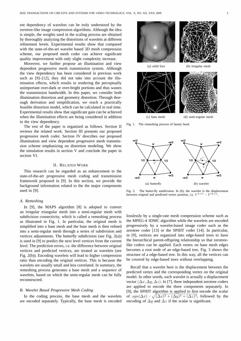
In [9], the MAPS algorithm [8] is adopted to convertan irregular triangular mesh into a semi-regular mesh withsubdivision connectivity, which is called a remeshing processas illustrated in Fig. 1. In particular, the original mesh issimplified into a base mesh and the base mesh is then refinedinto a semi-regular mesh through a series of subdivision andvertices adjustments. The butterfly subdivision (see Fig. 2(a))is used in [9] to predict the next level vertices from the currentlevel. The prediction errors, i.e. the difference between originalvertices and predicted vertices, are treated as wavelets (seeFig. 2(b)). Encoding wavelets will lead to higher compressionratio than encoding the original vertices. This is because thewavelets are usually small and less correlated. In summary,theremeshing process generates a base mesh and a sequence ofwavelets, based on which the semi-regular mesh can be fullyreconstructed.
B. Wavelet Based Progressive Mesh Coding
In the coding process, the base mesh and the waveletsare encoded separately. Typically, the base mesh is encoded
(a) solid face (b) irregular mesh
(c) base mesh (d) semi-regular mesh
Fig. 1. The remeshing process of bunny head.
(a) butterfly (b) wavelet
Fig. 2. The butter-fly subdivision. In (b), the wavelet is thedisplacementbetween original and predicted vertex position, i.e.V L+1 − V ′L+1.
losslessly by a single-rate mesh compression scheme such asthe MPEG-4 3DMC algorithm while the wavelets are encodedprogressively by a wavelet-based image coder such as thezerotree coder [13] or the SPIHT coder [14]. In particular,in [9], vertices are organized into edge-based trees to havethe hierarchical parent-offspring relationship so that zerotree-like coders can be applied. Each vertex on base mesh edgesbecomes a root node of an edge-based tree. Fig. 3 shows thestructure of a edge-based tree. In this way, all the verticescanbe covered by edge-based trees without overlapping.
Recall that a wavelet here is the displacement between thepredicted vertex and the corresponding vertex on the originalmodel. In other words, each wavelet is actually a displacementvector(∆x,∆y,∆z). In [7], three independent zerotree codersare applied to encode the three components separately. In[9], the SPIHT algorithm is applied to first encode the scalarof sgn(∆x) ·
√
(∆x)2 + (∆y)2 + (∆z)2, followed by theencoding of∆y and∆z if the scalar is significant.

IEEE TRANSACTIONS ON CIRCUITS AND SYSTEMS FOR VIDEO TECHNOLOGY, VOL. X, NO. XX, XXX 2009 3
Fig. 3. An example of an edge-based tree, whereV L+2 is one of the fouroffsprings ofV L+1.
C. R-D Optimized Transmission
In [9], each edge-based tree is treated as a segment and anR-D function is developed for each segment. We will discussthe R-D modeling in detail in the subsequent sections. Supposethere is an R-D function for each segment, denoted asDk =fk(Rk), k = 1, 2, ..., n, whereDk and Rk are the distortionand the rate for thekth segment respectively, andn is the totalnumber of segments. During the transmission, the key questionis how to optimally allocate bits to each segment or tree sothat the total available bit budget can be well utilized. Such abit allocation problem can be formulated as follows: given acertain bit budgetR, how to find the optimalRk values thatminimize
∑n
k=1Dk =
∑n
k=1fk(Rk) subject to
∑n
k=1Rk =
R.This is an n-dimension constrained optimization problem. A
common solution is to use the Lagrange multiplier method. Inparticular, minimizing the distortion is the same as minimizingthe following equation with some value ofλ,
n∑
k=1
fk(Rk) + λ(
n∑
k=1
Rk − R). (1)
By differentiating the E.q. (1) with respect toRk, k =1, 2, ..., n, we obtain n equations:f
′
k(Rk) + λ = 0, k =1, 2, ..., n. Together with the constraint:
∑n
k=1Rk = R,
theoretically then+1 variables, i.e.λ andRk, k = 1, 2, ..., n,can be derived. In practice, there is usually no derivable for-mula for the above optimization problem. Instead, the greedyalgorithm is typically used to search the optimal solution in adiscrete solution space.
D. Quality Measurement
For 3D mesh coding, one of the key challenges is howto measure the quality. A popular metric is the Hausdorffdistance, which measures the distances between geometricshapes. However, this type of metric is not the same asthe perceived visual quality since it is defined purely fromthe geometry point of view. Several research studies havebeen conducted to find more appropriate quality metrics. Inparticular, Hoppe [10] proposed a view-dependent mesh metriccalled screen-space geometric error, which measures the geo-metric error after projecting geometry models in the viewing
Fig. 4. The diagram of our proposed wavelet based progressive mesh coder.
direction. Luebkeet al. [15] pointed out that the silhouetteregions are more important than interior regions and employeda tighter screen-space error threshold in the simplificationprocess. Reddy [16] proposed to select levels of detail (LODs)according to a fundamental perceptual model, and an updatedversion of the perceptual model was further proposed in [17].Although the perceptual model is not comprehensive, it doesachieve some desirable effects such as preserving silhouetteboundaries and high contrast details. However, the perceptualmodel requires tremendous computations.
III. R-D OPTIMIZED WAVELET-BASED PROGRESSIVE
MESH CODING
A. Problem Statement
As described in Section II-B, the existing wavelet based 3Dsemi-regular mesh coders directly extend the state-of-the-artwavelet-based image coders to compress the wavelet vectorsgenerated in the remeshing process. The main problem of theseapproaches is that the particular properties of semi-regularmeshes are not being taken into consideration. Specifically,in image compression, wavelet coefficients of an image atdifferent levels are independent from each other. A distortionof a coefficient at a coarser level does not affect the distortionof any other coefficient at a finer level. However, in 3Dsemi-regular mesh compression, the situation becomes totallydifferent. That is, the wavelets in thelth level affect the vertexpositions in the(l + 1)th level and the subsequent levels dueto the subdivision operations. Thus, with the same error, awavelet at a lower level contributes more to the total distortionthan a wavelet at a higher level.
It is well known that the principle of zerotree-like codersis to send the higher order bits of the larger magnitude coef-ficients first. Directly applying zerotree-like coders to encodesemi-regular meshes only considers the wavelet magnitudeswithout taking into account the dependency and the inherentunequal importance among different levels of wavelets. Thus,the generated progressive bitstream is not embedded since itis not guaranteed that the earlier portions of the progressivemesh bitstream are always more important than the later parts.
B. R-D Optimized Progressive Coding
Fig. 4 shows the diagram of our proposed wavelet basedprogressive mesh coder. Basically, we add one new compo-nent, “scaling”, between the remeshing component and thecoding component. The purpose of the scaling component isto give different weights to wavelets in different levels sothattheir magnitudes can truly represent their importance. Oneadvantage of such a system is that it can directly employ theexiting remeshing and zerotree-like coding algorithms.
The key question in our proposed mesh coder is how toset the weights for different wavelets. In order to address this

IEEE TRANSACTIONS ON CIRCUITS AND SYSTEMS FOR VIDEO TECHNOLOGY, VOL. X, NO. XX, XXX 2009 4
question, we need to analyze the distortion. In our research,we consider using geometric distortion to measure the recon-structed mesh quality. The geometry distortion is typicallydefined as the mean square error between original verticesand reconstructed vertices, i.e.
D(M ′,M) =1
|V |∑
vi∈M,v′
i∈M
′
‖vi − v′
i‖2 (2)
where |V | is the total number of vertices, andvi and v′
i
denote the vertices in the original semi-regular meshM andthe reconstructed semi-regular meshM
′
, respectively.Since in the progressive representation vertices are rep-
resented by wavelets, it is highly desired to compute thedistortion through wavelets so that repeatedly reconstructingthe vertices can be avoided. As pointed out in [9], the meansquare error of vertices‖vi−v
′
i‖2 can be approximated by themean square error of wavelets‖wi −w
′
i‖2. However, they arenot exactly equal due to the dependency among the verticesat different levels.
In [9], a distortion model was proposed, which considers theerror propagation effect due to subdivision. In particular, asshown in Fig. 5(a), the distortion for the center solid circle inthe lth level will propagate to the other three types of verticesin the (l + 1)th level with the weights of 1/2,w and−w/2,respectively. Considering the valence of six feature for a semi-regular mesh, the error propagation effect (including itself)from a particular level to the next level is approximated by aweighting factor [9]
W = 12 + 6 × (1
2)2 + 6 × w2 + 12 × (−w
2)2
= 2.5 + 9w2 (3)
where w ranges from 0 to 1/8. Further taking into accountthe error propagation among multiple levels, the weight foradistortion in thelth level is defined as [9]
Wl = WL−l, l = 1, 2, . . . , L (4)
whereL is the total number of subdivision levels.Note that although the authors in [9] did consider the depen-
dency among the wavelets at different levels in their distortionmodel, they only applied it for the distortion estimation anddid not use it to improve the coding performance. Moreover,their derived weights shown in Eqs. (3) and (4) are roughapproximation because they assume the error propagationsof individual vertices are the same. The subsequent analysisfurther details the inaccuracy of such simple weights.
We first consider the simplest case, i.e.w = 0, and assumeall the wavelets at level 1 (base mesh is at level 0) have anuniform errore (see Fig. 5(b)). We study how the distortionsat level 1 are propagated to subsequent levels. In particular,considering a vertex on an edge is shared by two adjacenttriangles, it is clear that the distortion at level 1 for thisparticular triangle is3e2/2. As shown in Fig. 5(b), after thefirst level subdivision, the base triangle is divided into twotypes of triangles:T0 and T1. It can be observed that thevertices generated at different subdivision levels inT0 alwayshave the same errore while the new vertices inT1 are of
(a) error propagation
(b) wavelet errors after three times subdivision
Fig. 5. The error propagation weights and wavelet errors.
different wavelet errors, having a pattern of(k + 1) verticeswith an error of(k/2L−1)e, k = 1, 2, . . . , L. Adding all thedistortions together and removing the overlapping, we derivethe total distortion for this particular triangle as
dL = (5
164L +
1
4)e2 (5)
It also means that the distortion of3e2/2 introduced at levell will result in a total distortion ofdL−l+1. Therefore, theweight for a distortion at thelth level becomes
Wl =dL−l+1
3e2/2=
5
64L−l +
1
6, l = 1, 2, . . . , L (6)
Finally, the overall distortion is calculated as
D =
L∑
l=1
∑
wi∈M l
Wl · ‖wi − w′
i‖2 (7)
wherewi ∈ M l meanswi is used in thelth level refinement.We would like to point out that although the weight in
Eq. (6) is derived in the case with the subdivision parameterw = 0, it can be directly used for the other cases withw 6= 0.This is becausew ranges from 0 to 1/8 and the correspondingerror propagation is insignificant as shown in Eq. (3).
In our implementation, with the derived weight in Eq. (6),the scaling component in Fig. 4 changes a waveletwi, wi ∈M l, into
√Wlwi before the SPIHT encoding. To encode a
vector wavelet coefficient (△x, △y, △z) for a vertex, wepropose the following method. We first encode the scalar

IEEE TRANSACTIONS ON CIRCUITS AND SYSTEMS FOR VIDEO TECHNOLOGY, VOL. X, NO. XX, XXX 2009 5
of △l = sgn(△x) ·√
(△x)2 + (△y)2 + (△z)2, wheresgn(△x) denotes the sign of△x. After the scalar is encoded,△y/△l and△z/△l are lossless encoded with entropy coding.In this way, during decoding, the error caused by compressionis distributed to△x, △y, and△z in proportion.
IV. R-D OPTIMIZED ILLUMINATION AND V IEW
DEPENDENTTRANSMISSION
A. Progressive Transmission System
Now, we consider applying the developed 3D mesh coderfor progressive 3D mesh transmission. Our key idea is toconsider the view and illumination dependencies. Specifically,we try to avoid the transmission of the invisible portions andavoid the refinement of the perceptually unimportant over-dark or over-bright portions of a 3D model. In order to dothis, a 3D mesh needs to be partitioned into many segments.Fortunately, the adopted 3D mesh coder naturally organizesvertices into edge-based trees, each of which can be consideredas a segment.
In particular, in our research, a semi-regular mesh is dividedinto two components: base mesh and edge-based forest. Thevertices from the first time subdivision of the base mesh aretaken as roots for each edge-based tree. Clearly, the numberof trees in the forest is the same as the number of edgesin the base mesh. We use the MPEG-4 3DMC (3D meshcoding) algorithm to encode the base mesh while employingour proposed wavelet-based progressive mesh coder to encodeeach edge-based tree separately. In this way, the base meshis losslessly transmitted to the receiver, while the edge-basedtrees are progressively delivered according to the available bitbudget.
The key question is how to optimally allocate bits to eachsegment or tree so that the total available bit budget can bewell utilized, as discussed in section II-C. In other words,we need to decide which segment should be refined at whichlevel. In order to achieve that, we need to develop the R-Dfunction for each segment that takes the illumination and viewdependencies into consideration.
B. Illumination and View Dependent Distortion Modeling
In our research, we define the overall distortion as a combi-nation of geometry distortion and illumination distortion, i.e.
D = Du + λDs, (8)
where we use the screen-space distortionDs to measure thegeometry distortion,Du denotes the illumination distortion,andλ is a user defined weight. In the following, we describeour developed models forDs andDu in detail.
1) Geometry Distortion:In section III, we have derived thegeometry distortion in Eq. (7). Now, we consider the factor ofviewing direction. In our research, we assume that the vieweris located at a far distance and thus orthogonal projection isused, i.e., the viewing direction is the same for all the vertices.
Let V denote the normalized viewing direction. We use thescreen-space error metric, which calculates the geometricerror
Fig. 6. The Blinn-Phong shading model.
projected on the screen. Specifically, the total view-dependentscreen space error for thekth segment is
Dsk =
L∑
l=1
∑
vi∈M lk
ai · |(vi − v′
i) × V |2
=
L∑
l=1
∑
vi∈M lk
ai · Wl · |(wi − w′
i) × V |2 (9)
where ai is either 1 or 0, indicating whether the vertex isvisible or not,Wl is the weight derived in Eq. (6), andvi ∈ M l
k
meansvi is a new vertex introduced in thelth refinement ofthe kth segment.
We can easily obtainai by checking the angle between thevertex normalNi with the view directionV . If the angle isless thanπ/2, the vertex is visible; otherwise, it is invisible.To simplify the computation, for all the vertices within onesegmentk, we assign the same normal directionNk since thevertices in one segment are around the the neighborhood of abase mesh edge and their normal directions are close to eachother. We calculateNk as the average of two neighboringbase triangle normals. In this way, the computation ofai canbe done as follows:
ai =
{
1, (Nk · V ) > 0;0, (Nk · V ) ≤ 0.
(10)
2) Illumination Distortion: In this study, we use the Blinn-Phong shading model [18] as the illumination model (shownin Fig. 6). Let L be the normalized lighting vector for adirectional light source, andNi be the normal vector of thesurface atvi. The intensityIi at vertexvi is given by
Ii =
{
Iaka + Idkd(Ni · L) + Isks(Ni · H)m, (Ni · L) > 0;Iaka, (Ni · L) ≤ 0;
(11)where ka, kd and ks are the ambient, diffuse and specularmaterial coefficients,Ia, Id and Is are the correspondingluminance, andHi, called the halfway vector, is defined asL+V|L+V | .
The vertex position error ofvi will affect the normal vectorat vi, and thus the illumination of its neighborhood will alsobe affected. We define the illumination distortiondi at vi as
di = bi · Si · (Ii − I′
i)2 (12)
whereI′
i is the corresponding intensity for the reconstructedvertex v
′
i, Si is the surrounding triangle area, i.e.Si =

IEEE TRANSACTIONS ON CIRCUITS AND SYSTEMS FOR VIDEO TECHNOLOGY, VOL. X, NO. XX, XXX 2009 6
∑6
j=1Si,j , andbi is the projection ofSi on the screen, which
is defined as
bi =
{
Nk · V, (Nk · V ) > 0;0, (Nk · V ) ≤ 0.
(13)
Based on the illumination model in Eq. (11), the illumina-tion error can be derived as follows:
Ii − I′
i = Idkd(Ni · L) + Isks(Ni · H)m − Idkd(N′
i · L)
− Isks(N′
i · H)m (14)
= Idkd[(Ni − N′
i ) · L] + Isks[(Ni · H)m − (N′
i · H)m]
≈ Idkd[(Ni − N′
i ) · L] + Isksm[(Ni − N′
i ) · H](Ni · H)m−1
whereN′
i is the corresponding normal for the reconstructedvertexv
′
i and the last step approximation is based on first-orderTaylor expansion.
In order to compute the illumination error in Eq. (14), weneed to compute the normal vector changeNi − N
′
i . Thecommon way to compute a vertex normal is through averagingits surrounding triangle normals, which requires to reconstructvertex positions. Such a method is computationally prohibitivesince we need to consider all the possible reconstructed vertexpositions. In order to avoid that, we simply approximate avertex normal as a weighted average of the surrounding edges,i.e.
Ni ≈1
6
6∑
j=1
(vi − vi,j)
Ei,j
(15)
wherevi,j , j = 1, 2, ..., 6 are the six surrounding vertices for avertexvi, andEi,j , the edge length of(vi −vi,j), is to reducethe sensitivity of the calculation by the edge length. Accordingto Eq. (15), the normal vector change can be approximatelyderived as
Ni − N′
i ≈ 1
6
6∑
j=1
(vi − vi,j) − (v′
i − vi,j)
Ei,j
=1
6
6∑
j=1
vi − v′
i
Ei,j
≈ wi − w′
i
Ei
(16)
where 1
Ei= 1
6
∑6
j=1
1
Ei,j.
Note that Eq. (15) is by no means an accurate method fornormal calculation. However, it works fine for our particularpurpose, i.e. computing the illumination distortion, due to thefollowing reasons. First, it is a good normal approximationfor the cases where each vertex has a valence of six andthe vertices are distributed more or less uniformly, whichis quite common for semi-regular meshes. Second, althoughthe approximation of Eq. (15) causes problems in the casesof locally planar regions, where it produces normal vectorslying in the planes, and concave regions, where we obtain thenormals in opposition direction, it does not have a great effecton computing the magnitude of the normal difference, whichplays the key role for computing the illumination distortion.
Substituting Eq. (16) back to Eq. (14) together with using(Nk · H)m−1 to approximate(Ni · H)m−1, and further sub-stituting Eq. (14) back to Eq. (12), we derive
di = bi
Si
E2i
{c21[(wi − w
′
i) · L]2 + c22[(wi − w
′
i) · H]2
+ 2c1c2[(wi − w′
i) · L][(wi − w′
i) · H]} (17)
= bi
Si
E2i
{c21[(wi − w
′
i) · L]2 + c22[(wi − w
′
i) · H]2
+ 2c1c2[(wi − w′
i) · H′
]2 − c1c2|wi − w′
i|2[1 − (L · H)]},
whereH′
= L+H|L+H| , c1 = Id ·kd, c2 = Is ·ks ·m(Nk ·H)m−1,
and the derivation of the last step is based on the property ofdot product derived in Appendix.
Finally, the total illumination distortion for thekth segmentcan be expressed as
Duk =
L∑
l=1
∑
vi∈M lk
Wl · di, (18)
whereWl is to compensate the approximation of‖vi − v′
i‖2
by ‖wi − w′
i‖2.3) Distortion Model Simplification:For practical applica-
tions of 3D mesh transmission, given the viewing and lightingparameters, we need to perform optimal bit allocation amongdifferent segments in real-time. The distortion model describedby Eqs. (9) and (18) are computationally intensive. This isbecause for one set of viewing and lighting parameters, weneed to compute the distortions for each vertex under differentbit rates, which is impractical. Therefore, in this subsection, wefurther develop a simplified distortion model. The basic idea isto separate the wavelet distortion from the viewing and lightingparameters. In particular, we approximate any dot product inthe form of [(wi −w
′
i) ·A]2 into |wi −w′
i|2 · (Nk ·A)2, whereA denotes a vector andNk is the normal vector for thekthsegment.
With such a simplification, the screen-space distortion forthe kth segment becomes,
Dsk = ak|Nk × V |2
L∑
l=1
∑
vi∈M lk
Wl|wi − w′
i|2. (19)
The illumination distortion for thekth segment becomes,
Duk = bk{c2
1(Nk · L)2 + c2
2(Nk · H)2 + 2c1c2(N
k · H ′
)2
−c1c2[1 − (L · H)]} · (L
∑
l=1
∑
vi∈M lk
Wl
Si
E2i
|wi − w′
i|2), (20)
whereak andbk are defined in Eqs. (10) and (13).To computeSi andEi, we make use of the two base trian-
gles and their edges since in the one-to-four subdivision theshape of the four off-spring triangles in the next level is similarto that of the two base triangles. In particular, we denote thetwo base triangle areas asSk,1 andSk,2, and the surroundingedge length asEk,j , j = 1, 2, .., 6, as shown in Fig. 7. Fora particular vertexvi, we have the following approximations:

IEEE TRANSACTIONS ON CIRCUITS AND SYSTEMS FOR VIDEO TECHNOLOGY, VOL. X, NO. XX, XXX 2009 7
Fig. 7. The estimations of edge length and triangle area.
1
Ei= 1
6
∑6
j=1
1
Ek,j× 2l and Si =
Sk,1+Sk,2
2× 1
4l . Thus, wederive
Si
E2i
=Sk,1 + Sk,2
72 × (∑6
j=1
1
Ek,j)2
, (21)
which is a constant for all the vertices within one segment.Based on the developed simplified distortion model, for each
segment we only need to compute∑L
l=1
∑
vi∈M lkWl|wi−w
′
i|2once, which is independent of view and lighting parametersand can be pre-computed. During the online transmission, onlythe view and lighting dependent portions in Eqs. (19) and(20) need to be calculated. In this way, the view and lightingdependent transmission can be achieved in real time.
V. SIMULATION RESULTS
A. Results of Progressive Mesh Compression
We implement the proposed wavelet based 3D mesh coderby adopting the MAPS algorithm [8] for remeshing and SPIHTfor encoding wavelet coefficients. We test on two 3D graphicsmodels, “Venus” and “Armadillo”.
First, we evaluate the accuracy of our proposed distortionmodel. Fig. 8 shows the results of the distortion estimation,where our proposed distortion model uses the derived weightgiven in Eq. (6) while the previous model in [9] uses theweight given in Eq. (3). We would like to point out thatthe distortion model is a function of the wavelet distortions.Given a bit rate, it is needed to perform SPIHT decoding inadvance to obtain the individual wavelet distortions. It canbe seen from Fig. 8 that the estimated distortions by ourproposed model closely match the actual distortions at eachbit rate, much more accurate than using the previous model.This is mainly because we assign more accurate weights to thewavelet distortions at each level. Note that all the distortionresults here are normalized with respect to the distortion ofthe base mesh.
Second, we compare the wavelet based 3D mesh coderswith and without the scaling components. The rate-SNRperformance is shown in Fig. 9 and the reconstructed modelsat a particular bit rate are shown in Fig. 10. From Fig. 9,we can see that our proposed coder significantly outperformsthe state-of-the-art coder proposed in [9] with2 ∼ 3 dB gainat most of the bit rates. The reconstructed models in Fig. 10further demonstrate that our proposed coder achieves muchbetter perceived visual quality.
(a) [9] at 0.2 bpv (b) Proposed at 0.2 bpv
(c) [9] at 0.6 bpv (d) Proposed at 0.6 bpv
Fig. 10. The reconstructed models for Venus.
B. Results of View and Illumination Dependent 3D MeshTransmission
In this section, we test the performance of our proposeddistortion model that considers both view and illuminationdependencies. To illustrate the importance of the illuminationdistortion, we compare the approaches with and without theconsideration of the illumination distortion. In particular, oneis based on Eq. (19) and the other is based on both Eqs. (19)and (20). For simplicity, we detach the mesh coding part anddirectly select vertices for transmission.
Fig. 11 shows the comparison results. It can be seen thatunder the same number of vertices the approach consideringillumination can achieve much better visual quality. This isbecause it gives more refinement for the important parts whileallocating less number of vertices for unimportant parts. Onone hand, both approaches consider the view dependency andthus do not refine the invisible parts, as shown in Fig. 11(a).On the other hand, the approach considering illumination giveshigher priorities to the parts with high contrast, which leads tothe better performance. In particular, the invisible back side isnot refined at all for a front view direction (see Fig. 11). Forthefront side, the approach without considering the illuminationheavily refines the parts that contribute to the boundariesequally throughout the face. However, with shading enabled,some boundaries become visually more important than others.The approach considering illumination gives more refinementfor these visually important boundary parts. The experimentalresults for other models are shown in Fig. 12.
Fig. 13 gives the progressive transmission performance with

IEEE TRANSACTIONS ON CIRCUITS AND SYSTEMS FOR VIDEO TECHNOLOGY, VOL. X, NO. XX, XXX 2009 8
0.1 0.2 0.3 0.4 0.5 0.6 0.7 0.8 0.9 10
0.1
0.2
0.3
0.4
0.5
0.6
0.7
0.8
0.9
1
Bits per vertex (bpv)
Dis
tort
ion
actual distortionmodel in [9]proposed distortion model
(a) Venus
0.1 0.2 0.3 0.4 0.5 0.6 0.7 0.8 0.9 10
0.1
0.2
0.3
0.4
0.5
0.6
0.7
0.8
0.9
1
Bits per vertex (bpv)
Dis
tort
ion
actual distortion
model in [9]
proposed distortion model
(b) Armadillo
Fig. 8. Distortion estimation.
0 0.2 0.4 0.6 0.8 1 1.2 1.4 1.6 1.8 20
5
10
15
20
25
30
35
40
Bits per vertex (bpv)
SN
R (
dB)
method [9]proposed method
(a) Venus
0 0.2 0.4 0.6 0.8 1 1.2 1.4 1.6 1.8 20
5
10
15
20
25
30
35
Bits per vertex (bpv)
SN
R(d
B)
method [9]proposed method
(b) Armadillo
Fig. 9. The comparison of the rate-SNR performance.
(a) invisible back side (b) visible front side with illumina-tion shading disabled
(c) visible front side with illumina-tion shading enabled
Fig. 11. The performance comparison for Venus with a bandwidthof 20% vertices. Top: without considering illumination. Bottom: considering illumination.

IEEE TRANSACTIONS ON CIRCUITS AND SYSTEMS FOR VIDEO TECHNOLOGY, VOL. X, NO. XX, XXX 2009 9
Fig. 12. From top to bottom: Armadillo, Horse, Lucy, Santa. Leftmost: without considering illumination. Rightmost: with theconsideration of illumination.Middle: corresponding zoom-in parts. For all the models, we set λ = 0.5 and the bandwidth to be 20% vertices.

IEEE TRANSACTIONS ON CIRCUITS AND SYSTEMS FOR VIDEO TECHNOLOGY, VOL. X, NO. XX, XXX 2009 10
Fig. 13. The progressive transmission performance withIa = Id = Is = 1.0, ka = 0.2, kd = 0.8, ks = 1.0 andm = 10. The four columns from left toright: considering illumination (front-view), not considering illumination (front-view), not considering illumination (side-view), and considering illumination(side-view).

IEEE TRANSACTIONS ON CIRCUITS AND SYSTEMS FOR VIDEO TECHNOLOGY, VOL. X, NO. XX, XXX 2009 11
5% ∼ 20% of the total number of vertices. It can be seenthat the performance gain of our proposed system is moreprominent at lower total available bandwidth.
VI. CONCLUSION
We have made two main contributions in this research. Thefirst contribution is that we have derived the weighting functionshown in Eq. (6), which can accurately reflect the importanceof wavelets at different refinement levels. Based on the derivedweight, we proposed to scale up the vector wavelets generatedin remeshing so that the inherent importance of wavelets canbe truly utilized by the zerotree-like compression algorithms.Experimental results have demonstrated that our proposedmesh coder significantly outperforms the existing one. Oursecond major contribution is the illumination distortion modelderived in Eq. (20). Combined with the geometry distortionmodel in Eq. (19), we obtained an overall distortion modelthat considers both illumination and view dependencies. Thisis a significant contribution since to the best of our knowledgenone of the existing progressive mesh transmission systemshas considered the illumination effects. Based on our deriveddistortion model, given the viewing and lighting parameters,we are able to optimally allocate bits among different segmentsin real time. Simulation results show that significant qualityimprovement can be achieved by taking into account theillumination effects in addition to the view dependency.
R-D analysis has been extensively used in the areas ofimage/video coding and transmission and various R-D modelshave been developed. Although there are a few studies on R-Danalysis for reconstructing 3D meshes [9] or 3D scenes [19],the overall research is falling behind. This is mainly becauseof the complexity of 3D models and the unpopularity ofnetworked 3D applications in the past. Our research only shedssome lights on the R-D analysis for 3D mesh coding and trans-mission. There are various ways to extend our work such asdeveloping more accurate R-D models, considering robustnessissues and extending to dynamic 3D meshes. The main focusfor the research in this direction is not about applying thetechniques for image and video to meshes in a straightforwardmanner but about designing methods that consider the uniquefeatures of 3D mesh coding and transmission.
APPENDIX
Here, we derive the expression of(N · L)(N · V ) used inEq. (17), whereN is an arbitrary vector andL and V aretwo arbitrary unit vectors. Suppose the geometry relationshipamongN , L, V is the same as that amongNi, L, V in Fig. 6.
Since L and V are unit vectors,(N · L)(N · V ) can bewritten asA = (|N | cos α)(|N | cos β), whereα andβ are theangles between the corresponding two vectors. Then, we can
have
A = |N |2 cos(α + β) + cos(α − β)
2
= |N |2[ (L · V )
2+ cos(
α − β
2)2 − 1
2]
= |N |2[ (L · V )
2+
(N · H)2
|N |2 − 1
2]
= (N · H)2 − |N |2 1 − (L · V )
2(22)
whereH = L+V|L+V | . For the case that the geometry relationship
amongN , L, V is different from that illustrated in Fig. 6, wecan perform similar derivation and the final expression is thesame.
ACKNOWLEDGMENT
The authors would like to thank Dr. Jae-Young Sim andProf. Chang-Su Kim for sharing their source codes for thework in [9]. Some 3D models are obtained from the Stanford3D Scanning Repository. The authors would also like tothank anonymous reviewers for their valuable comments andsuggestions.
REFERENCES
[1] J. Zhang, J. Cai, W. Guan, and J. Zheng, “Re-examination ofapplyingwavelet based progressive image coder for 3D semi-regular meshcompression,” inIEEE ICME, 2008, pp. 617–620.
[2] W. Guan, J. Zhang, J. Cai, and J. Zheng, “Illumination and view depen-dent progressive transmission of semiregular meshes with subdivisionconnectivity,” in ACM Graphite, 2007, pp. 219–226.
[3] H. Hoppe, “Efficient implementation of progressive meshes,” Computers& Graphics, vol. 22, pp. 327–336, 1998.
[4] G. Taubin, A. Gueziec, W. Horn, and F. Lazarus, “Progressive forestsplit compression,” inACM SIGGRAPH, 1998, pp. 19–25.
[5] R. Pajarola and J. Rossignac, “Compressed progressive meshes,” IEEETrans. Vis. Comput. Graph., vol. 6, no. 1, pp. 79–93, 2000.
[6] J. Li and C.-C. Kuo, “Progressive coding of 3-d graphic models,” Proc.IEEE, vol. 86, no. 6, pp. 1052–1063, Jun. 1998.
[7] A. Khodakovsky, P. Schroder, and W. Sweldens, “Progressive geometrycompression,” inACM SIGGRAPH, 2000, pp. 271–278.
[8] A. W. F. Lee, W. Sweldens, P. Schroder, L. Cowsar, and D. Dobkin,“MAPS: Multiresolution adaptive parameterization of surfaces,” inACMSIGGRAPH, 1998, pp. 95–104.
[9] J.-Y. Sim, C.-S. Kim, C.-C. Kuo, and S.-U. Lee, “Rate-distortionoptimized compression and view-dependent transmission of 3D normalmeshes,”IEEE Trans. Circuit and Syst. Video Technol, vol. 15, no. 7,pp. 854–868, Jul. 2005.
[10] H. Hoppe, “View-dependent refinement of progressive meshes,” in ACMSIGGRAPH, Aug. 1997, pp. 189–198.
[11] S. Yang, C.-S. Kim, and C.-C. Kuo, “A progressive view-dependenttechnique for interactive 3D mesh transmission,”IEEE Trans. Circuitand Syst. Video Technol, vol. 14, no. 11, pp. 1249–1264, Nov. 2005.
[12] W. Guan, J. Cai, J. Zheng, and C. W. Chen, “Segmentation based view-dependent 3D graphics model transmission,”IEEE Trans. Multimedia,vol. 10, no. 5, pp. 724–734, Aug. 2008.
[13] J. M. Shapiro, “Embedded image coding using zerotrees of waveletcoefficients,”IEEE Trans. Signal Processing, vol. 41, no. 12, pp. 3445– 3462, Dec. 1993.
[14] A. Said and W. A. Pearlman, “A new fast and efficient image codecbased on set partitioning in hierarchical trees,”IEEE Trans. Circuit andSyst. Video Technol, vol. 6, no. 3, pp. 243–250, June 1996.
[15] D. Luebke and C. Erikson, “View-dependent simplification of arbitrarypolygonal environments,” inACM SIGGRAPH, 1997, pp. 199–208.
[16] M. Reddy,Perceptually Modulated Level of Detail for Virtual Environ-ments, Ph.D. Thesis, University of Edinburgh, 1997.
[17] ——, “Perceptually optimized 3D graphics,”IEEE Computer Graphicsand Applications, vol. 21, no. 5, pp. 68–75, 2001.

IEEE TRANSACTIONS ON CIRCUITS AND SYSTEMS FOR VIDEO TECHNOLOGY, VOL. X, NO. XX, XXX 2009 12
[18] J. F. Blinn, “Models of light reflection for computer synthesized pic-tures,” in ACM SIGGRAPH, 1977, pp. 192–198.
[19] E. Imre, A. A. Alatan, and U. Gudukbay, “Rate-distortionefficientpiecewise planar 3-D scene representation from 2-D images,”IEEETransactions on Image Processing, vol. 18, no. 3, pp. 483–494, March2009.