Progress Report on Chamber Dynamics and Clearing Farrokh Najmabadi, Rene Raffray, Mark S. Tillack,...
21
Progress Report on Chamber Dynamics and Clearing Farrokh Najmabadi, Rene Raffray, Mark S. Tillack, John Pulsifer, Zoran Dragovlovic (UCSD) Ahmed Hassanein (ANL) Laser-IFE Program Workshop May31-June 1, 2001 Naval Research Laboratory Electronic copy: http://aries.ucsd.edu/najmabadi/TALKS UCSD IFE Web Site: http://aries.ucsd.edu/IFE
-
date post
21-Dec-2015 -
Category
Documents
-
view
213 -
download
0
Transcript of Progress Report on Chamber Dynamics and Clearing Farrokh Najmabadi, Rene Raffray, Mark S. Tillack,...

Progress Report onChamber Dynamics and Clearing
Farrokh Najmabadi, Rene Raffray, Mark S. Tillack, John Pulsifer,Zoran Dragovlovic (UCSD)Ahmed Hassanein (ANL)
Laser-IFE Program Workshop
May31-June 1, 2001 Naval Research Laboratory
Electronic copy: http://aries.ucsd.edu/najmabadi/TALKSUCSD IFE Web Site: http://aries.ucsd.edu/IFE
Statement of Work:
Initiate development of a fully integrated computer code to model and study chamber dynamic and clearing. Deliver the core of the code including the input/output interfaces, the geometry definition and the numerical solution control for multi-species (multi-fluid), 2-D transient compressible Navier Stokes equations. Provide chamber wall-interaction modules, which include physics of melting; evaporation and sublimation; sputtering; macroscopic erosion; and condensation and redeposition.
Scope the range of chamber dynamics and clearing experiments that can be carried out in a facility producing 100-10,000 J of X-ray.
Work Started on March 20, 2001.
ANL subcontract in place and work by ANL has begun.
Statement of Work and Progress to Date

Breakdown of Chamber Clearing Research
Stage-1 code
Stage-2 code
Experiments
Application:
Experiment planning
Design study support
Stage 2 Code development
Core development
Wall-interaction modules
Validation & Module Integration
Doc. Documentation & release of the code
Validation & Module Integration
Adaptive Mesh routines Doc.
App.
Experiment planning
Experiment Design
Experiment Implementation
1st year 2nd year
Radiation transport

Chamber Dynamics Research—Summary Progress Report
We are working on characterization of key physical processes.
Comprehensive overall representation of physical processes in spatial and temporal forms;
Summary description for each process: its key parameters and assessment of its relative importance (for modeling priorities and experiment planning) and relevant data base;
Initial effort on code architecture development. Two excellent suggestions by NRL scientists are added to our code
development plans:• Bringing along a 1-D version of the code for fast prototyping of various
algorithms.• Consider using a Monte Carlo Code (e.g., DSMC) to calculate transport
coefficients when we are interested in fine scale structures in the chamber (e.g., information needed to assess target injection in the chamber).
Estimate of chamber pumping conditions and requirements.
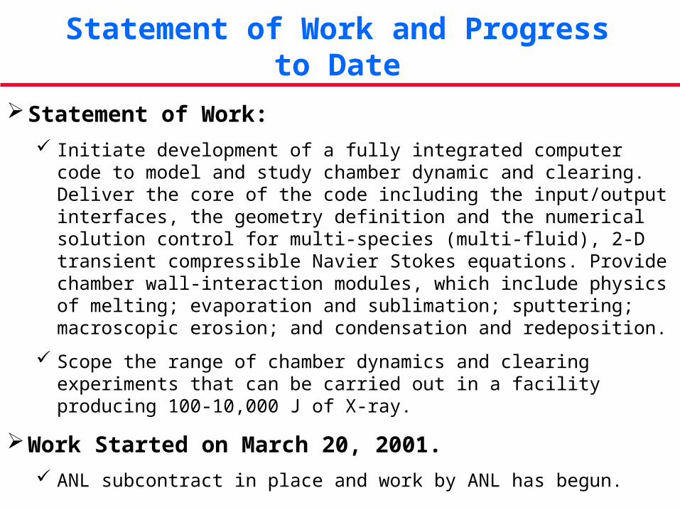
Cavity Gas, Target, and Wall Species
Chamber Dynamics Chamber Wall Interaction
Time of flight to wall:
X-rays ~20 ns
Neutrons ~100 nsAlphas ~400 nsFast Ions ~1 sSlow Ions ~1-10 s
• Photon transport & energy deposition
• Ion transport & energy deposition• Heating & ionization• Radiation• Gas dynamics (shock, convective
flow, large gradients, viscous dissipation)
• Condensation• Conduction• Cavity clearing Timescale: ns to 100 ms
• Convection & cooling
Timescale: ms
• Photon energy deposition• Ion energy deposition• Neutron & energy deposition• Conduction • Melting• Vaporization• Sputtering• Thermo-mechanics/
macroscopic erosion• Radiation damage• Blistering (from bubbles of
implanted gas)• Desorption or other degassing
process Timescale: ns to 100 ms
Coolant
Chamber Physics Modeling

Chamber Physics Modeling
Solid Wall mass loss
Establishing Fluid-wall
Chamber Region (multiphase, multispecies)Target Implosion Wall Region
Momentum Equations
Energy Equations
Conduction
Energy Eq.
Radiation transport
Condensation
Pressure (T)Viscous dissipation
Evaporation,Sputtering, etc.
Condensation
Evacuation
Phase change
Condensation
Stress/strain analysis Thermal Stress
Fluid-wall momentum Eq.
Kinetic energy
Conduction &ConvectionIon & photon transport Thermal
capacity
momentum transfer(impulse)
Density
Ion transportMass Equations
Velocity
Gas Feed
Condensation

Chamber Wall Evaporation
Physics: Kinetic model based on surface conditions, activation energies and temperature
Model: Use equilibrium conditions, equating evaporation and condensation fluxes. From
the kinetic theory of gases and using the Clausius-Clapeyron the condensing flux, G (kg/m2-s) (and, thus, the evaporation flux) can be expressed as:
RT
MPG
π
2= ;
P =10(A−
BT
);
qev'' =GHev
α coefficient of evaporation, or accommodation coefficient P Vapor pressure (Pa) of material at temperature T(K) M Molecular weight of material, R Universal gas constant (J/kmol-K) Hev Latent heat of evaporation (J/kg) qev” Evaporation heat flux, qev’’ (W/m2)
Key Parameters: Temperature, surface accommodation coefficient
Key Uncertainties: Comparison of simple equilibrium- basis equation with dynamic case; might
require correction terms.
Relative Importance: Possibly major mechanism for chamber wall mass evolution
Timescale: Comparable to energy-deposition time-scale
Spatial Location: Wall surface
Relation to other processes:
All processes affecting surface temperature evolution (i.e. energy deposition; thermal diffusion, recondensation)
Inclusion in the code: Must be included from the start in some form

Condensation
Physics: Physical model based on surface conditions, area factor, Ac, non-condensable scale factor, β, and surface temperature.
Model: The net condensation (similar to evaporation) rate can be calculated using the modified equation
[ ]gcsatsats
PATPRTM
G βπ
−√√↵
= )(
2
2/1
α accommodation coefficient Ts surface temperature of target material Psat saturation pressure at temperature Ts Pg pressure of vapor in contact with the surface β and Ac are scaling factors.
Key Parameters: Surface temperature of target material, saturation pressure (f(Ts)),
accommodation coefficient, scaling factors.
Key Uncertainties: Scaling factors, details of volume condensation model and of micro-site cavity recondensation (site characteristic dimension), aerosol formation & transport.
Relative Importance: A major mechanism for wall mass evolution and chamber clearing procedure.
Timescale: Time between energy-deposition time up to next shot.
Spatial Location: Wall surfaces and vicinity (for volume condensation), chamber cavity.
Relation to other
processes: All processes affecting surface temperature evolution, modified surface properties.
Inclusion in the code: Must be included from the start in some form .

Physical Sputtering
Physics: Physical model depends on wall material, energy of ion debris, incident particle angles (normal in this case).
Model: Developed model is based on semi-empirical formula and on 3-D Monte Carlo models that depends on energy of ion debris and burn products and their spectra.
Key Parameters: Energy of incident ion debris, wall material, long-term radiation effects. Key Uncertainties: Energy of ion debris with and without gas protection, characteristics of surface
modified layer during operation. Relative Importance: Tends to be a threshold mechanism and to peak at a certain ion energy; e.g. for
C, it peaks at ion energy of ~ 1 keV. Possibly not a major mechanism for chamber wall erosion and mass evolution, in particular for cases with no or very low protective gas pressure and high energy incident ions (~1 MeV)
Timescale: Comparable to energy-deposition time-scale. Spatial Location: Wall surface and in particular near surface modified layer. Relation to other
processes: All processes affecting particle transport and energy deposition with or without gas.
Inclusion in the code: Could be included from the start particularly for cases with gas protection and low evaporation and low macroscopic erosion regime, but with lower priority

Example: Physical Sputtering of C
Sputtering yield peaks at ~1 keV and decreases with increasing ion energy level. Could be important for debris ions but not for fast ions. Sputtering yield peaks at an angle of incidence of ~80°.
From J. Roth, et al., “Erosion of Graphite due to Particle Impact,” Nuclear Fusion, 1991.

Chemical Sputtering (Carbon)
Physics: Chemical sputtering is associated mainly with C and arises from the formation of volatile molecules such as CO, CO2 and/or CxHy Physical model is based on the carbon wall material, hydrogen debris spectra, and wall temperature.
Model: Model is based on semi-analytical approach and fitting formula.
Key Parameters: Incident ion debris energy (with and without gas protection), ion flux, surface
temperature.
Key Uncertainties: Surface temperature, modified surface layer, radiation effects.
Relative Importance: Chemical sputtering yield peaks at ion energy level of ~0.5 keV and temperature of ~800K. Should not be a major mechanism of chamber wall mass evolution in comparison with evaporation and macroscopic erosion.
Timescale: Comparable to energy-deposition time-scale.
Spatial Location: Wall near surface layer.
Relation to other
processes: All processes affecting surface temperature evolution and incident ion energy
Inclusion in the code: Could be included from the start particularly for cases with gas protection and low evaporation and low macroscopic erosion regime, but with lower priority

Radiation Enhanced Sublimation
Physics: Radiation enhanced sublimation (RES) is associated with C and the hypothesis is that it results from the creation of vacancy-interstitial pairs by nuclear collisions and the diffusion of interstitials to the surface where they sublimate thermally with low binding energy. Physical model is based on the carbon wall material, ion debris spectra, and wall temperature.
Model: Model is based on semi-analytical approach and fitting formula.
Key Parameters: Incident ion debris energy (with and without gas protection), ion flux, surface
temperature.
Key Uncertainties: Surface temperature, modified surface layer, radiation effects.
Relative Importance: RES yield increases dramatically with temperature and peaks at ion energy level of ~1 keV. Should not be a major mechanism of chamber wall mass evolution in comparison with evaporation and macroscopic erosion.
Timescale: Comparable to nuclear collision time-scale.
Spatial Location: Wall, near surface layer.
Relation to other
processes: All processes affecting surface temperature evolution and incident ion energy.
Inclusion in the code: Could be included from the start particularly for cases with gas protection and low evaporation and low macroscopic erosion regime, but with lower priority.

Example: Radiation Enhanced Sublimation of C
●
●
● ●
●
◆
◆
◆◆ ◆
◆
■
■
■■ ■
■
▲
▲
▲▲
▲ ▲
1.0x10⁻³
1.0x10⁻²
1.0x10⁻¹
1.0x100
1.0x101 1.0x10² 1.0x10³ 1.0x10⁴ 1.0x10⁵ 1.0x10⁶
Ion energy (eV)
He (1870K)
D (1870K)
H (1870K)
H (1500K)
From J. Roth, et al., “Erosion of Graphite due to Particle Impact,” Nuclear Fusion, 1991.
Dependence of RES on Incident Ion Energy and Material Temperature

Brittle Destruction of Carbon-Based-Materials
Physics: Brittle destruction is a form of macroscopic erosion mechanism due to intense energy deposition in carbon-based materials.
Model: Mechanism is based on thermal stresses and heating of vapor inside the porous graphite structure. The net destruction rate is function of incident energy flux and a specific energy of brittle destruction Qbrittle. Values for Qbrittle can be obtained from electron beam and plasma simulation experiments.
Key Parameters: Surface temperature and incident energy flux. Key Uncertainties: Specific energy for brittle destruction of original and modified graphite wall
material. Relative Importance: Could be a major wall erosion mechanism of carbon-based-materials. For
irradiated materials due to large porosity, brittle destruction erosion can significantly increase in comparison with original material (before irradiation).
Timescale: Energy-deposition time-scale up to heat diffusion time in structure. Spatial Location: Wall and modified surface layers. Relation to other
processes: All processes affecting surface temperature evolution and energy deposition, modified surface properties, particle implantation, and pore structure.
Inclusion in the code: Should be included (if not from the start in the subsequent modeling phase) assuming reasonable value of the specific energy of destruction from simulation experiments.

Splashing Erosion of Melting Materials
Physics: Ablation erosion of melting materials as a result of splashing of molten layers. Model: Due to both hydrodynamics instabilities and the volume bubble boiling and
explosion splashing erosion of molten layers can take place. Part or all of the developed molten layer may be lost and splashed in the form of liquid metal droplets. The net splashing rate is function of incident power flux and specific energy of splashing Qsplash and molten layer properties
Key Parameters: Temperature of surface material, specific energy for splashing for wall material, incident power flux, hydrodynamic motion of protected gas (plasma) near surface of molten layers, molten layer properties.
Key Uncertainties: Specific energy of splashing, hydrodynamic motion of protected gas (plasma) near surface of molten layers and hydrodynamic motion of molten layers.
Relative Importance: Can be the major erosion mechanism of metallic first wall materials. Can significantly affect wall lifetime.
Timescale: Energy-deposition time-scale and hydrodynamic gas protection time-scale. Spatial Location: Wall surface and molten layers and vicinity of protected gas layers. Relation to other
processes: All processes affecting surface temperature evolution, spatial velocity distribution of molten layers, protected gas motion near surface, and surface properties
Inclusion in the code: Should be included (if not from the start in the subsequent modeling phase) with some reasonable value of the specific energy of splashing for melting wall materials and reasonable hydrodynamic behavior of protected gas near surface.

Interaction of Photons with Matter
Physics: X-ray energy deposition in material: photoelectric effect, Compton scattering.
Model: Photon transport (1-D for wall).
Key Parameters: Photon energy, wall composition.
Key Uncertainties: Cross sections (depending on the material)
Relative Importance: Energy flux to the wall, radiation transport in the chamber.
Timescale: ~ 1-10 ns
Spatial Location: Chamber cavity and chamber wall
Relation to other
processes:
Thermal and mass transfer evolution of chamber wall, dynamics of mass and thermal evolution of chamber gas
Inclusion in the code: Energy flux on wall should be included from the start

Interaction of Ions with Matter
Physics: Electronic stopping and nuclear stopping processes Model: Electronic stopping power: model is dependent on ion energy level:
Bethe model for >1MeVand Lindhard model for <1 MeV Nuclear stopping power: conventional model
Key Parameters: Ion energy, material composition Key Uncertainties: Mostly in transition regime (~1 MeV) for electronic stopping power Relative Importance: Energy flux to the wall.
Timescale: ~1-10 s Spatial Location: Chamber cavity and chamber wall Relation to other
processes: Thermal and mass transfer evolution of chamber wall and chamber gas.
Inclusion in the code: Energy flux on wall should be included from the start

Chamber Dynamics Research—Summary Progress Report
We are working on characterization of key physical processes.
Comprehensive overall representation of physical processes in spatial and temporal forms;
Summary description for each process: its key parameters and assessment of its relative importance (for modeling priorities and experiment planning) and relevant data base;
Initial effort on code architecture development. Two excellent suggestions by NRL scientists are added to our code
development plans:• Bringing along a 1-D version of the code for fast prototyping of various
algorithms.• Consider using a Monte Carlo Code (e.g., DSMC) to calculate transport
coefficients when we are interested in fine scale structures in the chamber (e.g., information needed to assess target injection in the chamber).
Estimate of chamber pumping conditions and requirements.

Chamber Pumping Options
Basic Assumptions:
Chamber is 5m radius (524 m3) and is at constant temperature of 1000 K.
Chamber is pumped through laser beam ports with pump located 1-m from the chamber wall (100 outlet, 50 cm diameter).
Molecular flow (Kn > 0.01 for pressures below 25 mTorr).
Pumping speed limited by duct conductance (C = 1 x 10⁶ liter/sec for Xe).
Ignore out-gassing of chamber wall.
Ignore gas in the beam ducts (only chamber is pumped).
Can we evacuate the chamber between shots (i.e., pump out Xe and debris to 100 times below equilibrium pressure)?
No. Even assuming zero leak rate and ignoring gas in beam ports, it takes 2.4 s to pump from P to 0.01P (for any starting pressure of Xe.)

Inject Xe with the targets (10 times the number density of Xe as the number density of target material).
Throughput of the vacuum system depends on pressure (conductance is constant with constant temperature).
Shot frequency dictates throughput of injected materials.
Chamber Pumping Option: Continuing Recycling of Chamber Gas
• Assumed No leaks.
Max shot rate: (targets + Xe) throughput =vacuum system throughput

It will be very difficult to maintain chamber pressure below ~ 20 mTorr! At ~50 mTorr and above, shot rate is NOT limited by pumping.
Continuing Recycling of Chamber Gas:Effect of Leaks