Progress in Nuclear Energy - erezgilad.files.wordpress.com · Monte Carlo and nodal neutron physics...
16
Monte Carlo and nodal neutron physics calculations of the IAEA MTR benchmark using Serpent/DYN3D code system Marat Margulis, Erez Gilad * The Unit of Nuclear Engineering, Ben-Gurion University of the Negev, Beer Sheva 84105, Israel article info Article history: Received 19 August 2015 Received in revised form 1 December 2015 Accepted 21 December 2015 Available online xxx Keywords: Serpent DYN3D Monte Carlo Reactor physics Burnup Research reactor abstract As part of recent efforts to utilize NPPs computational methodologies to safety analysis of research re- actors, the Serpent and DYN3D codes were extensively compared with a variety of static and burnup calculations as defined in the IAEA benchmark for 10 MW MTR pool-type reactor. These calculations include unit cell calculations and few group constants generation, unit cell and full core k-eigenvalue and burnup calculations, and full core 3D flux and power distributions. The Serpent code capabilities as a lattice code for MTR plate-type fuel assemblies were evaluated and compared with EPRI-CELL and WIMS- D4 results and reference solutions for full 3D core models were compared with MCNP5 and OpenMC results. The DYN3D nodal diffusion code capabilities in modeling full 3D MTR cores were also evaluated using few group cross sections and assembly discontinuity factors obtained by Serpent unit cell calcu- lations. The DYN3D results were compared with Serpent, MCNP5 and OpenMC. © 2016 Elsevier Ltd. All rights reserved. 1. Introduction Research Reactors (RRs) are developed and built primarily as test facilities and neutron generators for vast range of scientific, industrial and medical purposes. Unlike commercial nuclear po- wer plants (NPPS), RRs are characterized by small core size, low total thermal power, high power density, low fuel and clad tem- peratures and low system pressure. Furthermore, the different fuel composition, geometric configuration and different ranges of relevant operational parameters constitute different neutronic and thermal-hydraulics designs (D'Auria and Bousbia-Salah, 2006; Adorni et al., 2006, 2007; Hamidouche et al., 2008). As a result, these reactors must meet different safety requirements and unique safety features to ensure their safe utilization in nominal and off-nominal operation conditions and safe shutdown in case of an emergency or an accident. Moreover, many research reactors are characterized by constantly changing operational environ- ment, e.g. irradiation of new materials and fuels, introduction of new instrumentation into the core, different core loading con- figurations, varying irradiation regimes and so on. Hence, the reactor safety analysis report is frequently updated and must include the analysis of a wide variety of safety related scenarios. Furthermore, the uniqueness of each RR and its experimental systems make the standardization of design, operation and licensing of RRs a non-trivial task (Hamidouche et al., 2008; Costa et al., 2011). The safety analysis methodology employed for existing NPPs is based on a well-established and very active international com- munity of experts, well founded and proven methods and computational tools including best-estimate codes and uncer- tainty analysis, international standardization and extensive and accessible experimental database (D'Auria et al., 2006; Bousbia- Salah and D'Auria, 2007). During the last decade, the IAEA and others (Hamidouche et al., 2004; D'Auria and Bousbia-Salah, 2006; IAEA, 2007; Costa et al., 2011) have acknowledged the importance of implementing the well-founded and mature NPP safety technology (methods, codes, regulations and guidelines) in RRs safety analysis methodology and reassess their safety features (Adorni et al., 2007). However, the characteristics of RRs are different from those for NPP, due to different geometries and design, fuel compositions, structural materials and thermal-hydraulic operation regime (Hamidouche et al., 2004; D'Auria and Bousbia-Salah, 2006; Chat- zidakis et al., 2014). The adequacy of applying NPP computational * Corresponding author. E-mail address: [email protected] (E. Gilad). Contents lists available at ScienceDirect Progress in Nuclear Energy journal homepage: www.elsevier.com/locate/pnucene http://dx.doi.org/10.1016/j.pnucene.2015.12.008 0149-1970/© 2016 Elsevier Ltd. All rights reserved. Progress in Nuclear Energy 88 (2016) 118e133
Transcript of Progress in Nuclear Energy - erezgilad.files.wordpress.com · Monte Carlo and nodal neutron physics...

lable at ScienceDirect
Progress in Nuclear Energy 88 (2016) 118e133
Contents lists avai
Progress in Nuclear Energy
journal homepage: www.elsevier .com/locate/pnucene
Monte Carlo and nodal neutron physics calculations of the IAEA MTRbenchmark using Serpent/DYN3D code system
Marat Margulis, Erez Gilad*
The Unit of Nuclear Engineering, Ben-Gurion University of the Negev, Beer Sheva 84105, Israel
a r t i c l e i n f o
Article history:Received 19 August 2015Received in revised form1 December 2015Accepted 21 December 2015Available online xxx
Keywords:SerpentDYN3DMonte CarloReactor physicsBurnupResearch reactor
* Corresponding author.E-mail address: [email protected] (E. Gilad).
http://dx.doi.org/10.1016/j.pnucene.2015.12.0080149-1970/© 2016 Elsevier Ltd. All rights reserved.
a b s t r a c t
As part of recent efforts to utilize NPPs computational methodologies to safety analysis of research re-actors, the Serpent and DYN3D codes were extensively compared with a variety of static and burnupcalculations as defined in the IAEA benchmark for 10 MW MTR pool-type reactor. These calculationsinclude unit cell calculations and few group constants generation, unit cell and full core k-eigenvalue andburnup calculations, and full core 3D flux and power distributions. The Serpent code capabilities as alattice code for MTR plate-type fuel assemblies were evaluated and compared with EPRI-CELL and WIMS-D4 results and reference solutions for full 3D core models were compared with MCNP5 and OpenMCresults. The DYN3D nodal diffusion code capabilities in modeling full 3D MTR cores were also evaluatedusing few group cross sections and assembly discontinuity factors obtained by Serpent unit cell calcu-lations. The DYN3D results were compared with Serpent, MCNP5 and OpenMC.
© 2016 Elsevier Ltd. All rights reserved.
1. Introduction
Research Reactors (RRs) are developed and built primarily astest facilities and neutron generators for vast range of scientific,industrial and medical purposes. Unlike commercial nuclear po-wer plants (NPPS), RRs are characterized by small core size, lowtotal thermal power, high power density, low fuel and clad tem-peratures and low system pressure. Furthermore, the differentfuel composition, geometric configuration and different ranges ofrelevant operational parameters constitute different neutronicand thermal-hydraulics designs (D'Auria and Bousbia-Salah,2006; Adorni et al., 2006, 2007; Hamidouche et al., 2008). As aresult, these reactors must meet different safety requirements andunique safety features to ensure their safe utilization in nominaland off-nominal operation conditions and safe shutdown in caseof an emergency or an accident. Moreover, many research reactorsare characterized by constantly changing operational environ-ment, e.g. irradiation of new materials and fuels, introduction ofnew instrumentation into the core, different core loading con-figurations, varying irradiation regimes and so on. Hence, the
reactor safety analysis report is frequently updated and mustinclude the analysis of a wide variety of safety related scenarios.Furthermore, the uniqueness of each RR and its experimentalsystems make the standardization of design, operation andlicensing of RRs a non-trivial task (Hamidouche et al., 2008; Costaet al., 2011).
The safety analysis methodology employed for existing NPPs isbased on a well-established and very active international com-munity of experts, well founded and proven methods andcomputational tools including best-estimate codes and uncer-tainty analysis, international standardization and extensive andaccessible experimental database (D'Auria et al., 2006; Bousbia-Salah and D'Auria, 2007). During the last decade, the IAEA andothers (Hamidouche et al., 2004; D'Auria and Bousbia-Salah,2006; IAEA, 2007; Costa et al., 2011) have acknowledged theimportance of implementing the well-founded and mature NPPsafety technology (methods, codes, regulations and guidelines) inRRs safety analysis methodology and reassess their safety features(Adorni et al., 2007).
However, the characteristics of RRs are different from those forNPP, due to different geometries and design, fuel compositions,structural materials and thermal-hydraulic operation regime(Hamidouche et al., 2004; D'Auria and Bousbia-Salah, 2006; Chat-zidakis et al., 2014). The adequacy of applying NPP computational

M. Margulis, E. Gilad / Progress in Nuclear Energy 88 (2016) 118e133 119
tools to RRs has been addressed in several thermal-hydraulictransients studies using RELAP5 (Woodruff et al., 1996, 1997;Bretscher et al., 1999; Deen et al., 1999; Hari et al., 2000; Adorniet al., 2005, 2006, 2007; Hedayat et al., 2007; Lu et al., 2009;Azzoune et al., 2010; Hamidouche and Bousbia-Salah, 2010; Omaret al., 2010; Reis et al., 2010; Chatzidakis et al., 2014; Khan et al.,2014; Soares et al., 2014; Abdelrazek et al., 2015), PARET (Deenet al., 1999; Housiadas, 2000; Chatzidakis et al., 2012, 2014), ATH-LET (Hainoun and Schaffrath, 2001), coupled NK/TH PARCS/RELAP5(Hamidouche et al., 2009), and COBRA-EN (Arshi et al., 2015).Recently, few studies solved the IAEA 10 MW MTR benchmark forthe purpose of validating advanced neutronic codes and data li-braries, e.g. MCNP5 (Bousbia-Salah et al., 2008) and OpenMC(Chaudri and Mirza, 2015).
The vast majority of the studies mentioned above utilize theIAEA benchmark for 10 MW Material Test Reactor (MTR) pool-typereactor for assessing their codes performances (IAEA, 1980). Thebenchmark was specified under the program of research reactorcore conversion from highly enriched uranium (HEU) to lowenrichment uranium (LEU) cores. The benchmark consists ofdetailed steady state neutronic and thermal-hydraulic calculationsand a range of different accident and transient scenarios (IAEA,1992). However, recent years show a growing trend of bench-marking codes against actual experimental measurements for codeevaluation (Chatzidakis et al., 2013, 2014), which became publiclyavailable. Such experimental data was collected and compiledduring the IAEA CRP 1496 activity between 2008 and 2013 (IAEA,2008, 2010, 2011, 2012, 2015) and other international efforts(Chatzidakis et al., 2013, 2014; Hainoun et al., 2014), and includesstatic measurements as well as neutronic and thermal-hydraulictransient data.
The main goal of this article is to evaluate the Serpent MonteCarlo code (Leppanen, 2007; Leppanen et al., 2015) capabilities asa lattice code for MTR plate-type fuel assemblies and the DYN3Dnodal diffusion code (Grundmann et al., 2000, 2005) capabilitiesin modeling full MTR cores. The calculation scheme utilizes theSerpent code for unit cell and burnup calculations, including fewgroup cross sections and assembly discontinuity factors genera-tion, as well as for reference full core calculations. The obtainedfew group constants are then used by the nodal code DYN3D forfull 3D core benchmark. Once the DYN3D utilization for static MTRreactor calculation is completed and verified, the ultimate goal isto use it for transient analysis in research reactors. The DYN3D hasthe capability to solve the time dependent neutron diffusionequation for full 3D core couple to thermal-hydraulic channelcode, but it has not yet been employed for studying transients inresearch reactors.
The current study consists of three-dimensional Monte Carlo(MC) and deterministic nodal diffusion calculations, which arecompared with the results in (IAEA, 1980) and with EPRI-CELL,WIMSD4, MCNP5 and OpenMC codes (Bousbia-Salah et al.,2008; Chaudri and Mirza, 2015). For this purpose the latestversion of Serpent and DYN3D codes were used. This article re-ports on the first stage in the development of a transientthermal-hydraulic system code for research reactor accidentsanalysis e THERMO-T, which eventually will interface withthe core model of DYN3D via the core inlets and outlets anduse its three-dimensional nodal diffusion code (Margulis andGilad, 2015). THERMO-T is currently undergoing comprehensivecomparisons to different codes in different accident scenariosavailable in the IAEA TECDOC 643 (IAEA, 1992) and the IAEATechnical Reports Series No. 480 (IAEA, 2015), which provideboth numerical (code-to-code) and experimental data for reac-tivity insertion and loss of flow accidents for different types ofreactors.
2. Methodology
2.1. Serpent
Serpent is a continuous energy Monte Carlo neutron transportcode with burnup capabilities developed at VTT research center inFinland (Leppanen, 2007; Leppanen et al., 2015). This code allowsmodeling of complicated three-dimensional geometries, and wasdeveloped as an alternative to deterministic lattice codes for gen-eration of homogenized multigroup constants for reactor analysesusing nodal codes. The current version of Serpent contains librariesbased on JEFF-2.2, JEFF-3.1.1, ENDF/B-VI.8 and ENDF/B-VII evaluateddata files. In this work the ENDF/B-VII evaluated data files wereused.
The Serpent code has a number of features that dramaticallyreduces CPU time required for its execution, among them are aunified energy grid for storing cross section data and the use ofWoodcock delta-tracking of particles. Serpent also has a built-insubroutine for fuel depletion that is based on the CRAM method(Pusa, 2013). All nuclides and meta-stable states data contained inthe decay libraries are available for Serpent calculations, where thetotal number of different nuclides produced from fission, trans-mutation and decay reactions is in the order of 1500. The atomdensities of all included nuclides with decay data are tracked in theburnup calculation, and the number of nuclides with cross sectionstypically ranges from 200 to 300.
The depletion analysis can be performed with a predictor-corrector (PC) algorithm to get a more accurate estimate of iso-topic concentrations at each time step. In Serpent, there are twoways of tallying 1-g cross sections. The most accurate way istallying directly each type of reaction rate for each isotope in eachburnable material. In this study Serpent is used to generate fewgroup cross sections and assembly discontinuity factors as well asfor reference full core calculations.
2.2. DYN3D
The code DYN3D (Grundmann et al., 2000, 2005) is a three-dimensional coupled neutron kinetics and thermal-hydraulicscore code, developed at Helmholtz-Zentrum Dresden-Russendorf(HZDR) for dynamic and depletion calculations in light waterreactor cores with rectangular or hexagonal lattice geometry. Themultigroup neutron diffusion equation is solved by nodal methodscoupled to a thermal-hydraulic model (FLOCAL). The core ismodeled by parallel coolant channels which can describe one ormore fuel elements. Starting from the critical state (critical boronconcentration or critical power), the code allows to simulate theneutronic and thermal-hydraulic core response to reactivitychanges and/or changes of the coolant core inlet conditions. Crosssection libraries generated by different lattice codes for differentreactor types are linked with DYN3D. Although DYN3D wasdeveloped for analyzing power reactors and was intensively vali-dated and verified against power reactors benchmarks, it is shownin this study that DYN3D is also suitable for studying research re-actors, such as the one considered in this work.
2.3. Core description
In the current work both HEU and LEU cores were modeled. Thecore grid consists of 6� 7 grid, containing 21 fuel elements, 4control elements, and graphite and water reflectors. The geometryand dimensions of a standard fuel element is presented in Fig. 1.Each standard fuel element consists of 23 fuel plates, whereas thecontrol fuel elements contain 17 fuel plates, as shown in Fig. 2. Thecore configuration for both Beginning of Life (BOL) and End of Life
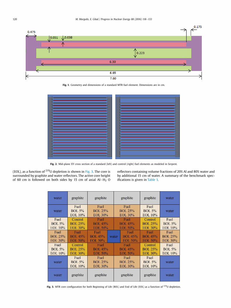
Fig. 1. Geometry and dimensions of a standard MTR fuel element. Dimensions are in cm.
Fig. 2. Mid-plane XY cross section of a standard (left) and control (right) fuel elements as modeled in Serpent.
M. Margulis, E. Gilad / Progress in Nuclear Energy 88 (2016) 118e133120
(EOL), as a function of 235U depletion is shown in Fig. 3. The core issurrounded by graphite and water reflectors. The active core heightof 60 cm is followed on both sides by 15 cm of axial AleH2 O
Fig. 3. MTR core configuration for both Beginning of Life (BO
reflectors containing volume fractions of 20% Al and 80% water andby additional 15 cm of water. A summary of the benchmark spec-ifications is given in Table 1.
L) and End of Life (EOL) as a function of 235U depletion.
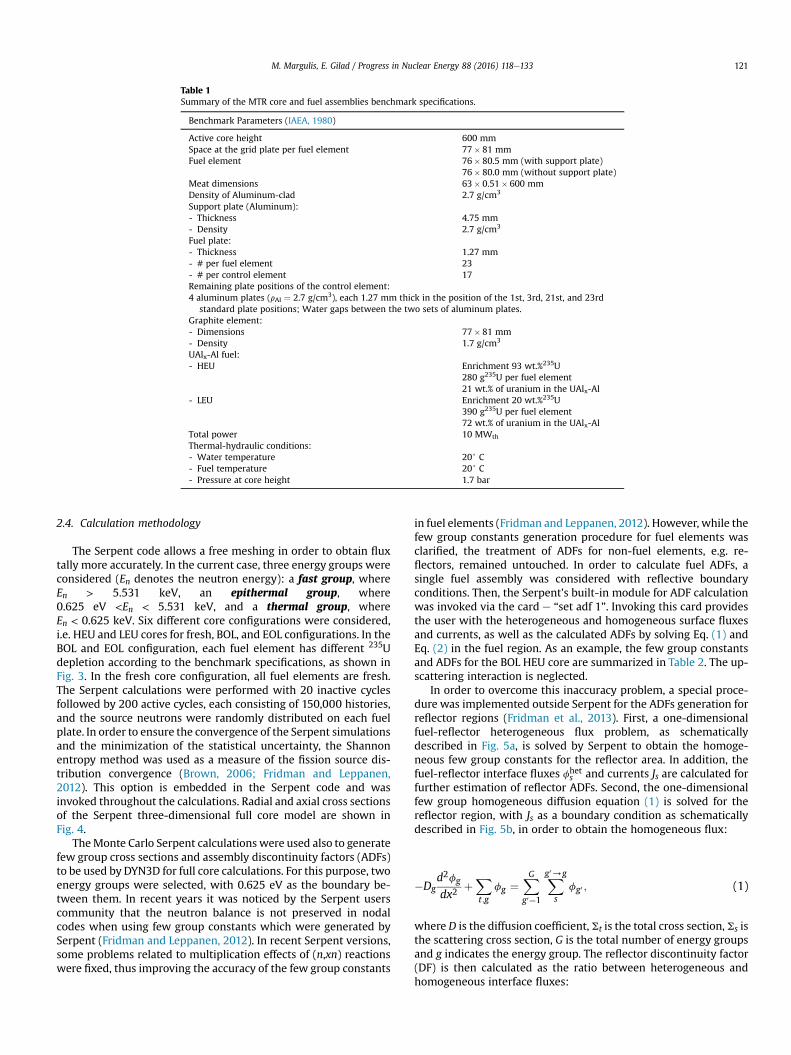
Table 1Summary of the MTR core and fuel assemblies benchmark specifications.
Benchmark Parameters (IAEA, 1980)
Active core height 600 mmSpace at the grid plate per fuel element 77� 81 mmFuel element 76� 80.5 mm (with support plate)
76� 80.0 mm (without support plate)Meat dimensions 63� 0.51� 600 mmDensity of Aluminum-clad 2.7 g/cm3
Support plate (Aluminum):- Thickness 4.75 mm- Density 2.7 g/cm3
Fuel plate:- Thickness 1.27 mm- # per fuel element 23- # per control element 17Remaining plate positions of the control element:4 aluminum plates (rAl ¼ 2.7 g/cm3), each 1.27 mm thick in the position of the 1st, 3rd, 21st, and 23rd
standard plate positions; Water gaps between the two sets of aluminum plates.Graphite element:- Dimensions 77� 81 mm- Density 1.7 g/cm3
UAlx-Al fuel:- HEU Enrichment 93 wt.%235U
280 g235U per fuel element21 wt.% of uranium in the UAlx-Al
- LEU Enrichment 20 wt.%235U390 g235U per fuel element72 wt.% of uranium in the UAlx-Al
Total power 10 MWth
Thermal-hydraulic conditions:- Water temperature 20+ C- Fuel temperature 20+ C- Pressure at core height 1.7 bar
M. Margulis, E. Gilad / Progress in Nuclear Energy 88 (2016) 118e133 121
2.4. Calculation methodology
The Serpent code allows a free meshing in order to obtain fluxtally more accurately. In the current case, three energy groups wereconsidered (En denotes the neutron energy): a fast group, whereEn > 5.531 keV, an epithermal group, where0.625 eV <En < 5.531 keV, and a thermal group, whereEn < 0.625 keV. Six different core configurations were considered,i.e. HEU and LEU cores for fresh, BOL, and EOL configurations. In theBOL and EOL configuration, each fuel element has different 235Udepletion according to the benchmark specifications, as shown inFig. 3. In the fresh core configuration, all fuel elements are fresh.The Serpent calculations were performed with 20 inactive cyclesfollowed by 200 active cycles, each consisting of 150,000 histories,and the source neutrons were randomly distributed on each fuelplate. In order to ensure the convergence of the Serpent simulationsand the minimization of the statistical uncertainty, the Shannonentropy method was used as a measure of the fission source dis-tribution convergence (Brown, 2006; Fridman and Leppanen,2012). This option is embedded in the Serpent code and wasinvoked throughout the calculations. Radial and axial cross sectionsof the Serpent three-dimensional full core model are shown inFig. 4.
TheMonte Carlo Serpent calculations were used also to generatefew group cross sections and assembly discontinuity factors (ADFs)to be used by DYN3D for full core calculations. For this purpose, twoenergy groups were selected, with 0.625 eV as the boundary be-tween them. In recent years it was noticed by the Serpent userscommunity that the neutron balance is not preserved in nodalcodes when using few group constants which were generated bySerpent (Fridman and Leppanen, 2012). In recent Serpent versions,some problems related to multiplication effects of (n,xn) reactionswere fixed, thus improving the accuracy of the few group constants
in fuel elements (Fridman and Leppanen, 2012). However, while thefew group constants generation procedure for fuel elements wasclarified, the treatment of ADFs for non-fuel elements, e.g. re-flectors, remained untouched. In order to calculate fuel ADFs, asingle fuel assembly was considered with reflective boundaryconditions. Then, the Serpent's built-in module for ADF calculationwas invoked via the card e “set adf 1”. Invoking this card providesthe user with the heterogeneous and homogeneous surface fluxesand currents, as well as the calculated ADFs by solving Eq. (1) andEq. (2) in the fuel region. As an example, the few group constantsand ADFs for the BOL HEU core are summarized in Table 2. The up-scattering interaction is neglected.
In order to overcome this inaccuracy problem, a special proce-dure was implemented outside Serpent for the ADFs generation forreflector regions (Fridman et al., 2013). First, a one-dimensionalfuel-reflector heterogeneous flux problem, as schematicallydescribed in Fig. 5a, is solved by Serpent to obtain the homoge-neous few group constants for the reflector area. In addition, thefuel-reflector interface fluxes fhet
s and currents Js are calculated forfurther estimation of reflector ADFs. Second, the one-dimensionalfew group homogeneous diffusion equation (1) is solved for thereflector region, with Js as a boundary condition as schematicallydescribed in Fig. 5b, in order to obtain the homogeneous flux:
�Dgd2fg
dx2þX
t;gfg ¼
XG
g0¼1
Xg0/g
sfg0 ; (1)
where D is the diffusion coefficient, St is the total cross section, Ss isthe scattering cross section, G is the total number of energy groupsand g indicates the energy group. The reflector discontinuity factor(DF) is then calculated as the ratio between heterogeneous andhomogeneous interface fluxes:
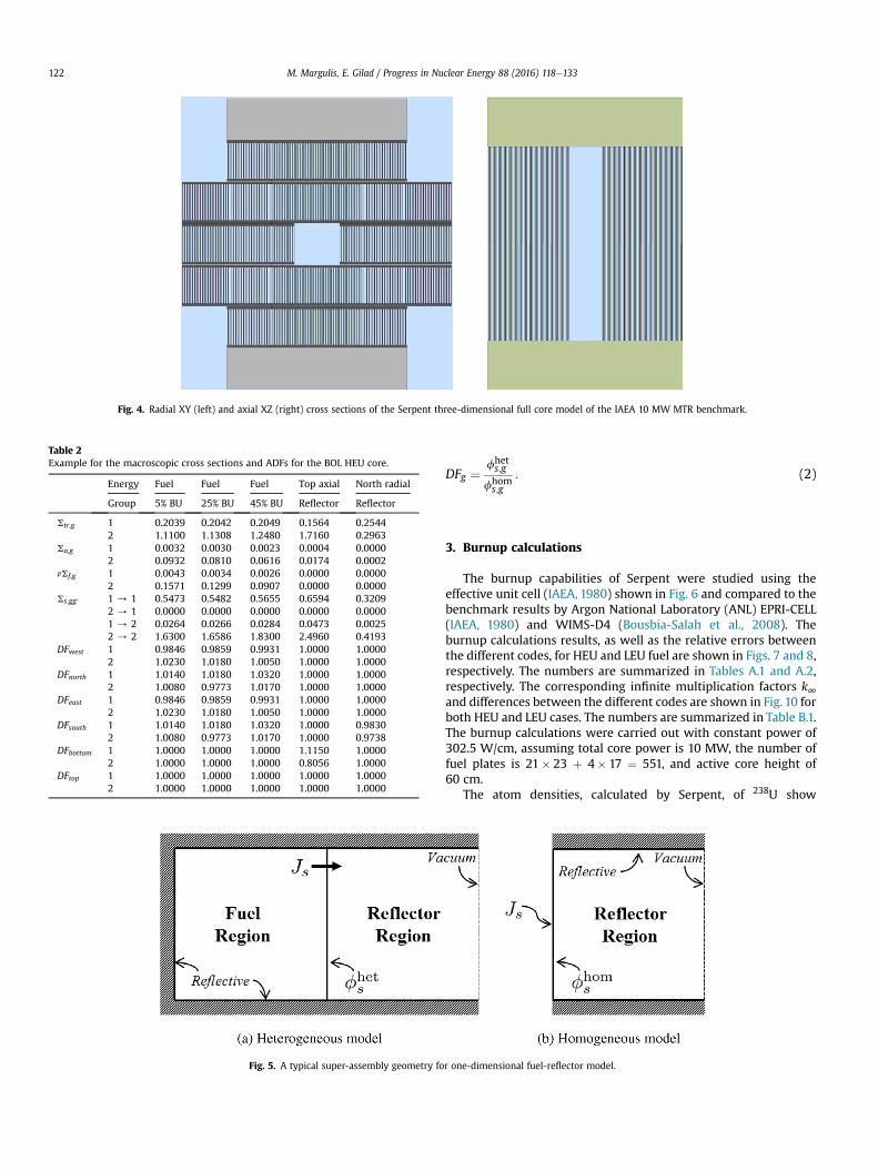
Fig. 4. Radial XY (left) and axial XZ (right) cross sections of the Serpent three-dimensional full core model of the IAEA 10 MW MTR benchmark.
Table 2Example for the macroscopic cross sections and ADFs for the BOL HEU core.
Energy Fuel Fuel Fuel Top axial North radial
Group 5% BU 25% BU 45% BU Reflector Reflector
Str,g 1 0.2039 0.2042 0.2049 0.1564 0.25442 1.1100 1.1308 1.2480 1.7160 0.2963
Sa,g 1 0.0032 0.0030 0.0023 0.0004 0.00002 0.0932 0.0810 0.0616 0.0174 0.0002
nSf,g 1 0.0043 0.0034 0.0026 0.0000 0.00002 0.1571 0.1299 0.0907 0.0000 0.0000
Ss;gg0 1 / 1 0.5473 0.5482 0.5655 0.6594 0.32092 / 1 0.0000 0.0000 0.0000 0.0000 0.00001 / 2 0.0264 0.0266 0.0284 0.0473 0.00252 / 2 1.6300 1.6586 1.8300 2.4960 0.4193
DFwest 1 0.9846 0.9859 0.9931 1.0000 1.00002 1.0230 1.0180 1.0050 1.0000 1.0000
DFnorth 1 1.0140 1.0180 1.0320 1.0000 1.00002 1.0080 0.9773 1.0170 1.0000 1.0000
DFeast 1 0.9846 0.9859 0.9931 1.0000 1.00002 1.0230 1.0180 1.0050 1.0000 1.0000
DFsouth 1 1.0140 1.0180 1.0320 1.0000 0.98302 1.0080 0.9773 1.0170 1.0000 0.9738
DFbottom 1 1.0000 1.0000 1.0000 1.1150 1.00002 1.0000 1.0000 1.0000 0.8056 1.0000
DFtop 1 1.0000 1.0000 1.0000 1.0000 1.00002 1.0000 1.0000 1.0000 1.0000 1.0000
Fig. 5. A typical super-assembly geometry fo
M. Margulis, E. Gilad / Progress in Nuclear Energy 88 (2016) 118e133122
DFg ¼ fhets;g
fhoms;g
: (2)
3. Burnup calculations
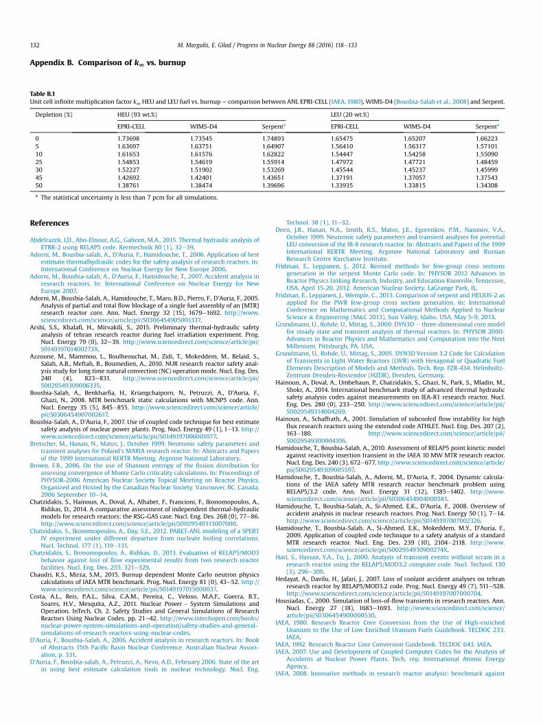
The burnup capabilities of Serpent were studied using theeffective unit cell (IAEA, 1980) shown in Fig. 6 and compared to thebenchmark results by Argon National Laboratory (ANL) EPRI-CELL(IAEA, 1980) and WIMS-D4 (Bousbia-Salah et al., 2008). Theburnup calculations results, as well as the relative errors betweenthe different codes, for HEU and LEU fuel are shown in Figs. 7 and 8,respectively. The numbers are summarized in Tables A.1 and A.2,respectively. The corresponding infinite multiplication factors k∞and differences between the different codes are shown in Fig. 10 forboth HEU and LEU cases. The numbers are summarized in Table B.1.The burnup calculations were carried out with constant power of302.5 W/cm, assuming total core power is 10 MW, the number offuel plates is 21� 23 þ 4� 17 ¼ 551, and active core height of60 cm.
The atom densities, calculated by Serpent, of 238U show
r one-dimensional fuel-reflector model.
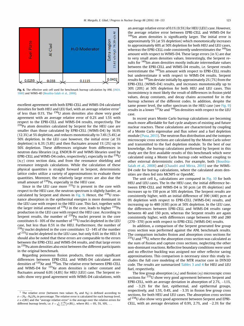
Fig. 6. The effective unit cell used for benchmark burnup calculation by ANL (IAEA,1980) and WIMS-4D (Bousbia-Salah et al., 2008).
M. Margulis, E. Gilad / Progress in Nuclear Energy 88 (2016) 118e133 123
excellent agreement with both EPRI-CELL and WIMS-D4 calculateddensities for both HEU and LEU fuel, with an average relative error1
of less than 0.1%. The 236U atom densities also show very goodagreement with an average relative error of 0.2% and 1.5% withrespect to the EPRI-CELL and WIMS-D4 results, respectively. The239Pu atom densities calculated by Serpent for the HEU case aresmaller than those calculated by EPRI-CELL (WIMS-D4) by 16.9%(12.3%) at 5% depletion, and reduces monotonically to 7.4% (5.4%) at50% depletion. In the LEU case however, the initial error (at 5%depletion) is 6.3% (5.8%) and then fluctuates around 1% (2%) up to50% depletion. These differences originate from differences inneutron data libraries (e.g. ENDF/B-IV and WIMS libraries used byEPRI-CELL andWIMS-D4 codes, respectively), especially in the 238U(n,g) cross section data, and from the resonance shielding andresonance integrals calculations. While the calculation of thesephysical quantities is straight forward in Serpent, deterministiclattice codes utilize a variety of approximations to evaluate thesequantities. Moreover, the relatively large errors are also due thesmall amount of 239Pu, especially in the HEU case.
Since in the LEU case more 235U is present in the core withrespect to the HEU case, the neutron spectrum is slightly harder, ascalculated by Serpent and shown in Fig. 9. Hence, the 238U reso-nance absorption in the epithermal energies is more dominant inthe LEU case with respect to the HEU case. This fact, together withthe larger initial amount of 238U in the core, leads to higher 239Puproduction in the LEU case with respect the HEU case. According toSerpent results, the number of 239Pu nuclei present in the coreconstitutes 6e10% of the number of 235U nuclei depleted in the LEUcase, but less than 0.5% in the HEU. Furthermore, the number of238U nuclei depleted in the core constitutes 12e14% of the numberof 235U nuclei depleted in the LEU case, but only 0.6% in the HEU. Itshould also be noted that these errors are comparable to the errorsbetween the EPRI-CELL and WIMS-D4 results, and that large errorsin 239Pu atomdensities also exist between the different participantsin the original benchmark.
Regarding poisonous fission products, there exist significantdifferences between EPRI-CELL and WIMS-D4 calculated atomdensities of 135Xe and 149Sm. The relative error between EPRI-CELLand WIMS-D4 for 135Xe atom densities is rather constant andfluctuates around 6.0% (4.8%) for HEU (LEU) case. The Serpent re-sults show very good agreement with WIMS-D4 calculations, with
1 The relative error (between two values NA and NB) is defined according toe¼ (NA�NB)/NA in percentage. The relative error is calculated for each burnup level,e ≡ e(BU) and the “average relative error” is the average over the relative errors fordifferent burnup levels, i.e. e ¼ 1
NBU
PNBUi¼1eðBUiÞ, where BUi ¼ 0%, 5%, 10%, ….
an average relative error of 0.1% (0.5%) for HEU (LEU) case. However,the average relative error between EPRI-CELL and WIMS-D4 for149Sm atom densities is significantly larger. The initial error isapproximately 5% (at 5% depletion) which monotonically increasesto approximately 60% at 50% depletion for both HEU and LEU cases,whereas the EPRI-CELL code consistently underestimates the 149Smamount with respect to WIMS-D4. These large errors (in %) are dueto very small atom densities values. Interestingly, the Serpent re-sults for 149Sm atom densities mostly indicate intermediate valuesbetween the EPRI-CELL and WIMS-D4 results, i.e. Serpent resultsoverestimate the 149Sm amount with respect to EPRI-CELL resultsbut underestimate it with respect to WIMS-D4 results. Serpentresults for 149Sm deviate initially by approximately 2% (7%) from theEPRI-CELL (WIMS-D4) results, and increases monotonically up to30% (20%) at 50% depletion for both HEU and LEU cases. Thisinconsistency is most likely the result of differences in fission yieldvalues, decay constants, and decay chains accounted for in theburnup schemes of the different codes. In addition, despite thesame power level, the softer spectrum in the HEU case (see Fig. 9)results in a lower 135Xe and 149Sm densities with respect to the LEUcase.
In recent years Monte Carlo burnup calculations are becomingmuch more affordable for fuel cycle analyses of existing and futurenuclear reactors. These calculations are characterized by couplingof a Monte Carlo eigenvalue and flux solver and a fuel depletionmodule (Pusa, 2013). The neutron flux distribution and the isotopesmicroscopic cross sections are calculated by the Monte Carlo solverand transmitted to the fuel depletion module. To the best of ourknowledge, the burnup calculations performed by Serpent in thisstudy are the first available results of this benchmark which werecalculated using a Monte Carlo burnup code without coupling toother external deterministic codes. For example, both (Bousbia-Salah et al., 2008) and (Chaudri and Mirza, 2015) use the WIMS-D4 code for burnup calculations, where the calculated atom den-sities are then fed into MCNP5 or OpenMC.
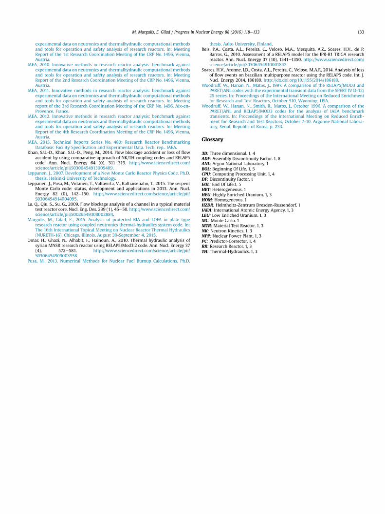
The unit cell k∞ calculations are compared in Fig. 10 for bothHEU and LEU cases. The In the HEU case, the initial difference be-tween EPRI-CELL and WIMS-D4 is 50 pcm (at 0% depletion) andincreases up to 150 pcm at 50% depletion. The Serpent results areconsistently higher, with an initial difference of 390 (440) pcm at0% depletion with respect to EPRI-CELL (WIMS-D4) results, andincreasing up to 480 (630) pcm at 50% depletion. In the LEU case,the differences between EPRI-CELL and WIMS-D4 results rangebetween 40 and 150 pcm, whereas the Serpent results are againconsistently higher, with differences range between 190 and 280(270e370) pcm with respect to EPRI-CELL (WIMS-D4) results.
In addition, a comparison of the Serpent generated few groupcross section was performed against the ANL benchmark results.The comparison includes fission and absorption cross sections for235U and 238U, where the absorption cross sectionwas calculated asthe sum of fission and capture cross sections, neglecting the othernon-dominant reactions. Reflective boundary conditions were usedand no effective buckling was assigned nor other reflector savingapproximations. This comparison is necessary since this study in-cludes the full core modeling of the MTR reactor core in DYN3Dcode. The results are summarized Tables 3 and 4 for HEU and LEUfuel, respectively.
The few group absorption (sa) and fission (sf) microscopic crosssections for 235U show very good agreement between Serpent andEPRI-CELL, with an average deviation in absorption of 2.7%, �1.1%,and �3.2% for the fast, epithermal, and epithermal groups,respectively, and 1.5%, 0.4%, and �3.3% in fission few group crosssections, for both HEU and LEU cases. The absorption cross sectionof 238U also show very good agreement between Serpent and EPRI-CELL, with an average deviation of 0.9%, 2.7%, and �2.3% for the

Fig. 7. Atom densities for HEU fuel vs. burnup e comparison and relative errors between ANL EPRI-CELL (IAEA, 1980), WIMS-D4 (Bousbia-Salah et al., 2008) and Serpent.
M. Margulis, E. Gilad / Progress in Nuclear Energy 88 (2016) 118e133124
HEU case and 0.9%,�4.6%, and�3.1% for the LEU case, as well as thefission cross sections of 238U for the fast group with an averagedeviation of �2.0% for both HEU and LEU. However, The fissioncross section of 238U calculated by Serpent for the epithermal groupis significantly larger than the one calculated by EPRI-CELL code forboth HEU and LEU (by a factor of ~3.5). Remaining plate positions ofthe to originate from pronounced differences in neutron data li-braries used by EPRI-CELL code (ENDF/B-IV) and Serpent (ENDF/B-VII.1).
4. Full core calculations
4.1. keff calculations
The effective multiplication factor keff of the different bench-mark cases, calculated by both Serpent and DYN3D using 2-groupscross sections and ADFs generated by Serpent, are compared withMCNP5 and OpenMC results in Table 5. As can be seen from Table 5,the results vary depending on the codes and neutron data libraries.However, the results of both Serpent and DYN3D are in an excellentagreement with one another, and in very good agreement withMCNP5 and OpenMC results.
The distinct effect of the usage of ADFs in full core calculations isdemonstrated in Table 5. The differences in keff values between
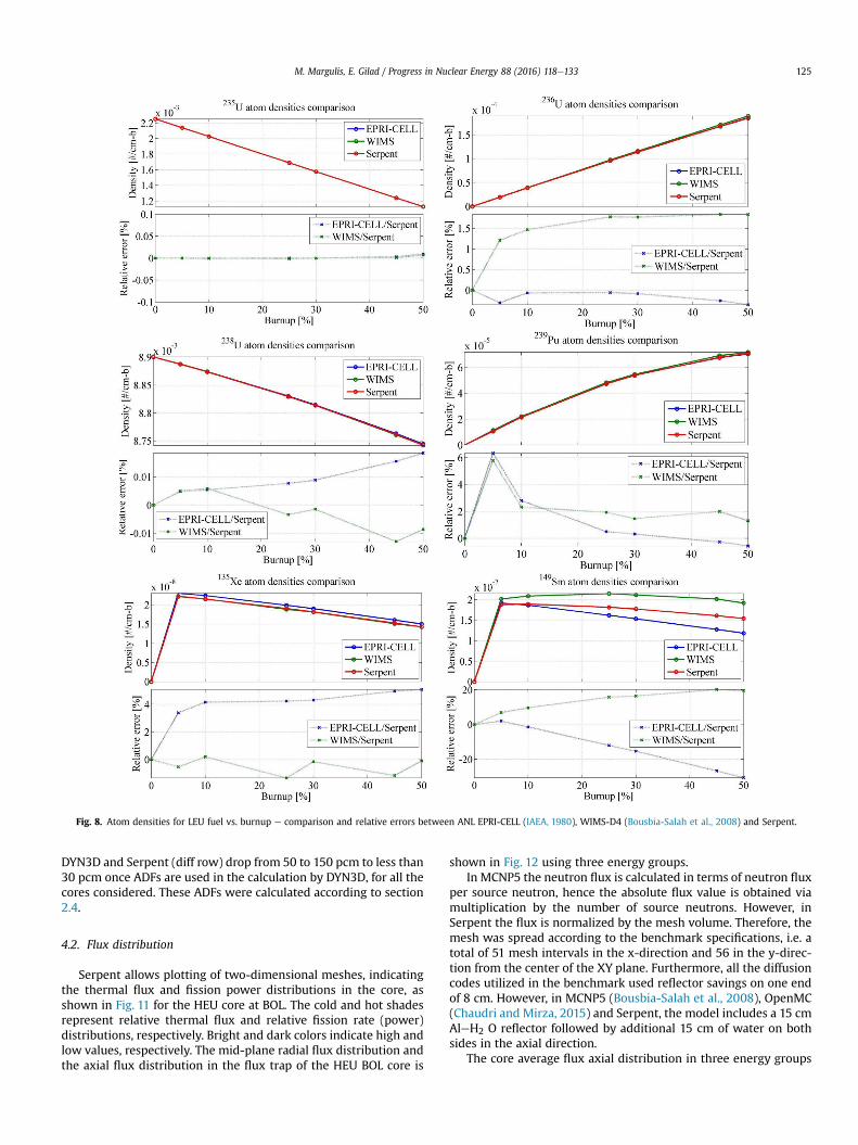
Fig. 8. Atom densities for LEU fuel vs. burnup e comparison and relative errors between ANL EPRI-CELL (IAEA, 1980), WIMS-D4 (Bousbia-Salah et al., 2008) and Serpent.
M. Margulis, E. Gilad / Progress in Nuclear Energy 88 (2016) 118e133 125
DYN3D and Serpent (diff row) drop from 50 to 150 pcm to less than30 pcm once ADFs are used in the calculation by DYN3D, for all thecores considered. These ADFs were calculated according to section2.4.
4.2. Flux distribution
Serpent allows plotting of two-dimensional meshes, indicatingthe thermal flux and fission power distributions in the core, asshown in Fig. 11 for the HEU core at BOL. The cold and hot shadesrepresent relative thermal flux and relative fission rate (power)distributions, respectively. Bright and dark colors indicate high andlow values, respectively. The mid-plane radial flux distribution andthe axial flux distribution in the flux trap of the HEU BOL core is
shown in Fig. 12 using three energy groups.In MCNP5 the neutron flux is calculated in terms of neutron flux
per source neutron, hence the absolute flux value is obtained viamultiplication by the number of source neutrons. However, inSerpent the flux is normalized by the mesh volume. Therefore, themesh was spread according to the benchmark specifications, i.e. atotal of 51 mesh intervals in the x-direction and 56 in the y-direc-tion from the center of the XY plane. Furthermore, all the diffusioncodes utilized in the benchmark used reflector savings on one endof 8 cm. However, in MCNP5 (Bousbia-Salah et al., 2008), OpenMC(Chaudri and Mirza, 2015) and Serpent, the model includes a 15 cmAleH2 O reflector followed by additional 15 cm of water on bothsides in the axial direction.
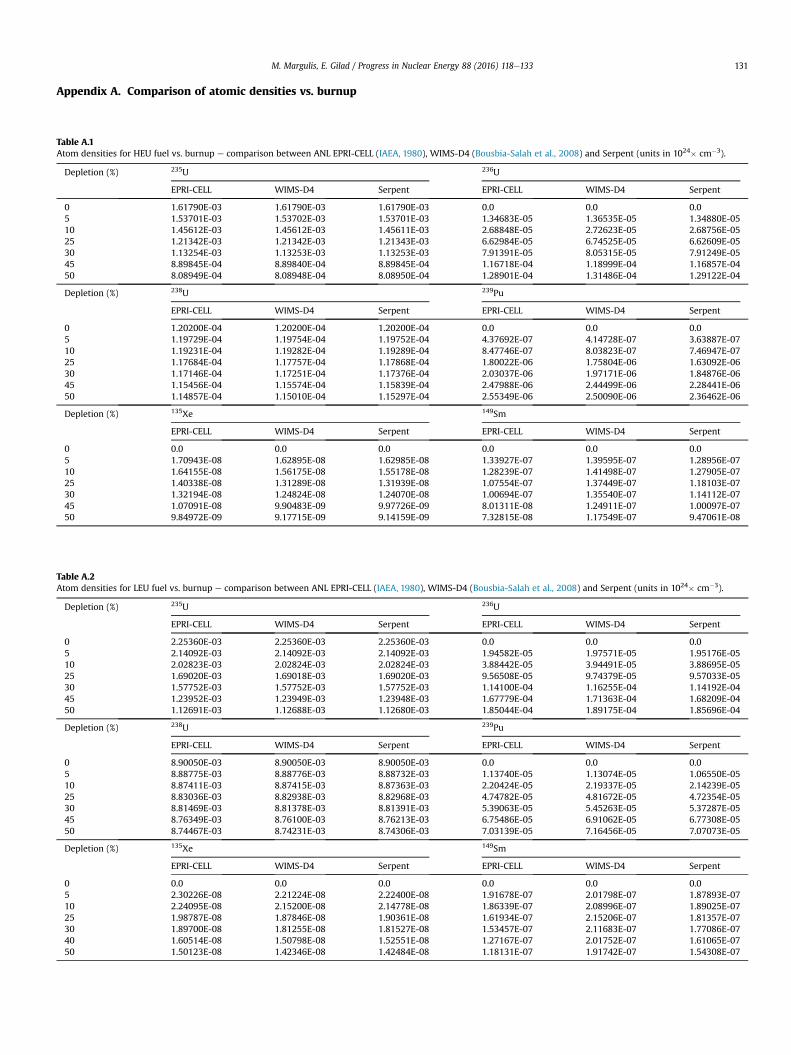
The core average flux axial distribution in three energy groups
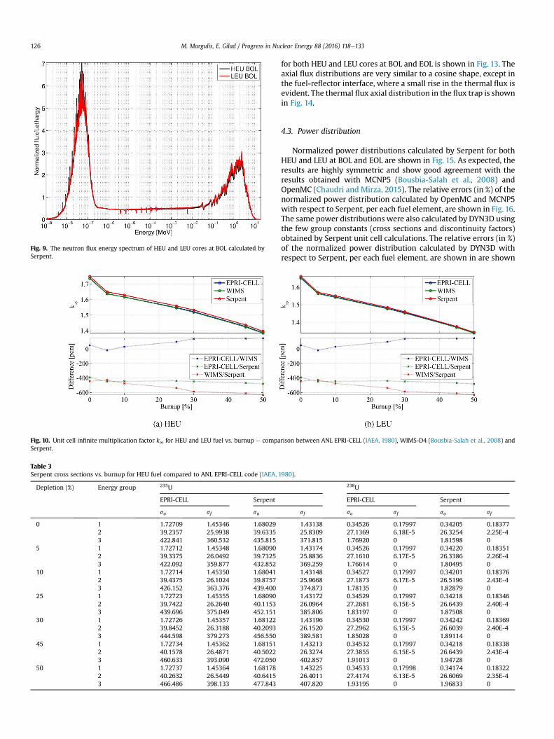
Fig. 9. The neutron flux energy spectrum of HEU and LEU cores at BOL calculated bySerpent.
Fig. 10. Unit cell infinite multiplication factor k∞ for HEU and LEU fuel vs. burnup e compaSerpent.
Table 3Serpent cross sections vs. burnup for HEU fuel compared to ANL EPRI-CELL code (IAEA, 1
Depletion (%) Energy group 235U
EPRI-CELL Serpent
sa sf sa
0 1 1.72709 1.45346 1.680292 39.2357 25.9938 39.63353 422.841 360.532 435.815
5 1 1.72712 1.45348 1.680902 39.3375 26.0492 39.73253 422.092 359.877 432.852
10 1 1.72714 1.45350 1.680412 39.4375 26.1024 39.87573 426.152 363.376 439.400
25 1 1.72723 1.45355 1.680902 39.7422 26.2640 40.11533 439.696 375.049 452.151
30 1 1.72726 1.45357 1.681222 39.8452 26.3188 40.20933 444.598 379.273 456.550
45 1 1.72734 1.45362 1.681512 40.1578 26.4871 40.50223 460.633 393.090 472.050
50 1 1.72737 1.45364 1.681782 40.2632 26.5449 40.64153 466.486 398.133 477.843
M. Margulis, E. Gilad / Progress in Nuclear Energy 88 (2016) 118e133126
for both HEU and LEU cores at BOL and EOL is shown in Fig. 13. Theaxial flux distributions are very similar to a cosine shape, except inthe fuel-reflector interface, where a small rise in the thermal flux isevident. The thermal flux axial distribution in the flux trap is shownin Fig. 14.
4.3. Power distribution
Normalized power distributions calculated by Serpent for bothHEU and LEU at BOL and EOL are shown in Fig. 15. As expected, theresults are highly symmetric and show good agreement with theresults obtained with MCNP5 (Bousbia-Salah et al., 2008) andOpenMC (Chaudri and Mirza, 2015). The relative errors (in %) of thenormalized power distribution calculated by OpenMC and MCNP5with respect to Serpent, per each fuel element, are shown in Fig. 16.The same power distributions were also calculated by DYN3D usingthe few group constants (cross sections and discontinuity factors)obtained by Serpent unit cell calculations. The relative errors (in %)of the normalized power distribution calculated by DYN3D withrespect to Serpent, per each fuel element, are shown in are shown
rison between ANL EPRI-CELL (IAEA, 1980), WIMS-D4 (Bousbia-Salah et al., 2008) and
980).
238U
EPRI-CELL Serpent
sf sa sf sa sf
1.43138 0.34526 0.17997 0.34205 0.1837725.8309 27.1369 6.18E-5 26.3254 2.25E-4371.815 1.76920 0 1.81598 01.43174 0.34526 0.17997 0.34220 0.1835125.8836 27.1610 6.17E-5 26.3386 2.26E-4369.259 1.76614 0 1.80495 01.43148 0.34527 0.17997 0.34201 0.1837625.9668 27.1873 6.17E-5 26.5196 2.43E-4374.873 1.78135 0 1.82879 01.43172 0.34529 0.17997 0.34218 0.1834626.0964 27.2681 6.15E-5 26.6439 2.40E-4385.806 1.83197 0 1.87508 01.43196 0.34530 0.17997 0.34242 0.1836926.1520 27.2962 6.15E-5 26.6039 2.40E-4389.581 1.85028 0 1.89114 01.43213 0.34532 0.17997 0.34218 0.1833826.3274 27.3855 6.15E-5 26.6439 2.43E-4402.857 1.91013 0 1.94728 01.43225 0.34533 0.17998 0.34174 0.1832226.4011 27.4174 6.13E-5 26.6069 2.35E-4407.820 1.93195 0 1.96833 0

Table 4Serpent cross sections vs. burnup for LEU compared to ANL EPRI-CELL code (IAEA, 1980).
Burnup (%) Energy group 235U 238U
EPRI-CELL Serpent EPRI-CELL Serpent
sa sf sa sf sa sf sa sf
0 1 1.72920 1.45441 1.68354 1.43301 0.34362 0.17851 0.34039 0.181882 37.8447 25.2009 38.3385 25.1447 6.09503 6.38E-5 6.36171 2.22E-43 392.606 334.476 407.323 347.369 1.65603 0 1.71211 0
5 1 1.72923 1.45443 1.68370 1.43315 0.34363 0.17851 0.34046 0.181962 37.9599 25.2617 38.4627 25.2189 6.10113 6.38E-5 6.36761 2.21E-43 391.023 333.106 406.202 346.389 1.64984 0 1.70782 0
10 1 1.72927 1.45445 1.68353 1.43304 0.34364 0.17851 0.34042 0.182082 38.0696 25.3164 38.5767 25.2752 6.10816 6.37E-5 6.38280 2.31E-43 394.540 336.114 409.687 349.386 1.66310 0 1.72067 0
25 1 1.72937 1.45452 1.68327 1.43287 0.34368 0.17853 0.34059 0.182092 38.3941 25.4691 38.8451 25.4170 6.13249 6.36E-5 6.40733 2.12E-43 406.711 346.645 421.104 359.191 1.70884 0 1.76245 0
30 1 1.72940 1.45454 1.68324 1.43292 0.34369 0.17854 1.98155 0.182322 38.5044 25.5196 38.9533 25.4595 6.14153 6.36E-5 6.43415 2.08E-43 411.253 350.562 425.381 362.864 1.72586 0 1.77808 0
45 1 1.72950 1.45461 1.68366 1.43319 0.34373 0.17856 0.34100 0.182352 38.8488 25.6786 39.2590 25.6158 6.17125 6.35E-5 6.46507 2.12E-43 426.484 363.692 439.960 375.371 1.78287 0 1.83119 0
50 1 1.72953 1.45463 1.68351 1.43310 0.34375 0.17856 0.34076 0.182452 38.9683 25.7349 39.3232 25.6220 6.18209 6.34E-5 6.47100 2.11E-43 432.191 368.610 445.683 380.277 1.80409 0 1.85198 0
Table 5Comparison of keff values, calculated by different codes, of the different cases defined in the benchmark (IAEA, 1980).
Organization (code) HEU (93 wt.%) LEU (20 wt.%)
Fresh BOL EOL Fresh BOL EOL
BGU (Serpent)a 1.18310 1.02392 1.00037 1.16636 1.02003 1.00074BGU (DYN3D without ADFs) 1.18391 1.02500 1.00128 1.16707 1.02157 1.00127diffb 58 pcm 102 pcm 90 pcm 52 pcm 147 pcm 57 pcmBGU (DYN3D with ADFs) 1.18333 1.02421 1.00038 1.16667 1.02000 1.00049diffc 16 pcm 27 pcm 1 pcm 21 pcm 3 pcm 25 pcmUPisa (MCNP5)d,e 1.18962 N/A N/A 1.17238 N/A N/APIEAS (OpenMC)d,e 1.19382 N/A N/A 1.15494 N/A N/A
a The statistical uncertainty is less than 27 pcm for all simulations.b Difference between Serpent and DYN3D without ADFs for axial and radial reflectors.c Difference between Serpent and DYN3D with ADFs for axial and radial reflectors.d HEU/LEU calculations are available with xenon-free conditions (Bousbia-Salah et al., 2008; Chaudri and Mirza, 2015).e The statistical uncertainty is less than 25 pcm.
Fig. 11. Serpent two-dimensional mesh plots indicating the thermal flux and fission power distributions in the HEU core at BOL. Cold and hot shades represent relative thermal fluxand relative fission rate (power) distributions, respectively. Bright and dark colors indicate high and low values, respectively (For interpretation of the references to colour in thisfigure legend, the reader is referred to the web version of this article.).
M. Margulis, E. Gilad / Progress in Nuclear Energy 88 (2016) 118e133 127
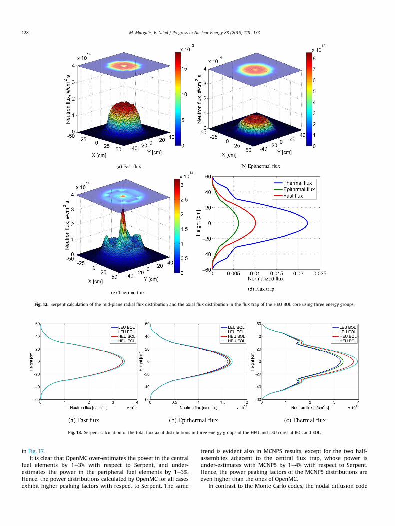
Fig. 12. Serpent calculation of the mid-plane radial flux distribution and the axial flux distribution in the flux trap of the HEU BOL core using three energy groups.
Fig. 13. Serpent calculation of the total flux axial distributions in three energy groups of the HEU and LEU cores at BOL and EOL.
M. Margulis, E. Gilad / Progress in Nuclear Energy 88 (2016) 118e133128
in Fig. 17.It is clear that OpenMC over-estimates the power in the central
fuel elements by 1e3% with respect to Serpent, and under-estimates the power in the peripheral fuel elements by 1e3%.Hence, the power distributions calculated by OpenMC for all casesexhibit higher peaking factors with respect to Serpent. The same
trend is evident also in MCNP5 results, except for the two half-assemblies adjacent to the central flux trap, whose power isunder-estimates with MCNP5 by 1e4% with respect to Serpent.Hence, the power peaking factors of the MCNP5 distributions areeven higher than the ones of OpenMC.
In contrast to the Monte Carlo codes, the nodal diffusion code

Fig. 14. Serpent calculation of the thermal flux axial distributions in the flux trap.
M. Margulis, E. Gilad / Progress in Nuclear Energy 88 (2016) 118e133 129
DYN3D under-estimates the power in the central fuel elements by2e3% with respect to Serpent, and over-estimates the power in theperipheral fuel elements by 2e4%. Hence, the power distributionscalculated by DYN3D for all cases exhibit lower peaking factorswith respect to Serpent. This is due to the fact that DYN3D solvesthe neutron diffusion equation, and despite the sophisticated nodalmethods, various transport corrections and the use of ADFs, diffu-sion approximation still tends to smooth the flux shape withrespect to neutron transport calculations. The larger relative errorsbetween DYN3D and Serpent occur in the four corner fuel elementsand are due to the 1D nature of the ADFs derivation, whichmight beinsufficient for these corner fuel elements. A 2D ADFs derivationprocedure should reduce this deviation. It should be noted that theasymmetry present in Fig. 17 is due to Serpent, since DYN3D resultsare completely symmetric.
Fig. 15. Normalized power distrib
5. Conclusions
The Serpent and DYN3D codes were extensively compared withEPRI-CELL, WIMS-D4, MCNP5 and OpenMC codes in a variety ofcalculations as defined in the IAEA benchmark for 10 MW MTRpool-type reactor (IAEA,1980). These calculations include both HEUand LEU fuel compositions, unit cell calculations and few groupconstants generation, unit cell and full core k-eigenvalues andburnup calculations, and full core 3D flux and power distributions.
The Serpent code (Leppanen, 2007; Leppanen et al., 2015) ca-pabilities as a lattice code for MTR plate-type fuel assemblies wereevaluated and reference solutions for full 3D core models of HEUand LEU at BOL and EOL were calculated. These calculations werecompared with MCNP5 and OpenMC results for keff, flux and powerdistributions. The DYN3D nodal diffusion code (Grundmann et al.,2000, 2005) capabilities in modeling full 3D MTR cores were alsoevaluated using few group cross sections and assembly disconti-nuity factors obtained by Serpent unit cell calculations. The DYN3Dresults were compared with Serpent, MCNP5 and OpenMC full corecalculations for keff, flux and power distributions.
The atom densities, calculated by Serpent, of uranium isotopes238U and 236U show excellent agreement with both EPRI-CELL andWIMS-D4 calculated densities for both HEU and LEU fuel. The dif-ferences in 239Pu densities result from differences in neutron datalibraries and approximated resonance shielding and resonanceintegrals calculations used by deterministic lattice codes. The Ser-pent results for 135Xe atom densities show very good agreementwith EPRI-CELL and WIMS-D4 calculations for both HEU and LEU,whereas significant differences exist in 149Sm densities betweenthe different codes. The Serpent results for 149Sm densities indicateintermediate values between the EPRI-CELL and WIMS-D4 results.This inconsistency is most likely the result of differences in fissionyield values, decay constants, and decay chains accounted for in theburnup schemes of the different codes. To the best of our knowl-edge, the burnup calculations performed by Serpent in this studyare the first available results of this benchmark which werecalculated using a Monte Carlo code without coupling to other
ution calculated by Serpent.

Fig. 16. Deviations (in %) of power distribution calculated by OpenMC and MCNP5 with respect to Serpent, per each fuel element. The different cases are ordered as indicated inFig. 15.
M. Margulis, E. Gilad / Progress in Nuclear Energy 88 (2016) 118e133130
external codes.The Serpent results for unit cell k∞ calculations are consistently
higher with respect to EPRI-CELL and WIMS-D4 results, withaverage differences of 490 and 280 pcm for HEU and LEU, respec-tively. These differences are not significant since the differencesbetween EPRI-CELL and WIMS-D4 results range between 50 and150 pcm.
A comparison of the Serpent generated few group cross sectionwas performed against the ANL benchmark results. The comparisonincludes fission and absorption cross sections for 235U and 238U inthree energy groupse fast, epithermal and thermal. The agreementis very good except for the fission cross section of 238U, where thevalues calculated by Serpent for the epithermal group are signifi-cantly larger than the ones calculated by EPRI-CELL code. These
Fig. 17. Deviations (in %) of power distribution calculated by DYN3D with respect toSerpent, per each fuel element. The different cases are ordered as indicated in Fig. 15.
differences are most likely due to pronounced differences inneutron data libraries used by EPRI-CELL code (ENDF/B-IV) andSerpent (ENDF/B-VII.1).
The effect of the usage of ADFs in full core calculations isdemonstrated in Table 5, where the differences in keff values be-tween DYN3D and Serpent drop once ADFs are used. Moreover, theresults of both Serpent and DYN3D are in a excellent agreementwith one another, and in very good agreement with the results ofother Monte Carlo codes, e.g. (Bousbia-Salah et al., 2008) and(Chaudri and Mirza, 2015).
The mid-plane radial flux distribution and the axial flux distri-bution in the flux trap are in very good agreement with the resultsin (IAEA, 1980) and in Bousbia-Salah et al. (2008); Chaudri andMirza (2015). The power distributions calculated by Serpent forall cases show good agreement with the results obtained withMCNP5 and OpenMC with small relative errors of up to 5% per fuelelement. Both MCNP5 and OpenMC exhibit higher peaking factorswith respect to Serpent. On the other hand, the nodal diffusion codeDYN3D exhibit lower peaking factors.
Finally, the capabilities of the Serpent/DYN3D code system tocalculate an MTR research reactor were demonstrated andcompared for steady state calculations. On-going and future workincludes the coupling of the Serpent/DYN3D code system to a timedependent thermal-hydraulic system code, THEMO-T, which isbeing developed at Ben-Gurion University (Margulis and Gilad,2015), for the purpose of accident analyses and asymmetric tran-sient calculations in research reactors. For further characterizationand establishment of our codes performances, we are currentlyengaged in benchmarking them against actual LOFA and RIAexperimental measurements performed in the ETRR-2, IEA-R1, andSPERT-IV reactors. The newly developed system code THERMO-T iscurrently undergoing comprehensive comparisons to differentcodes in different accident scenarios available in the IAEA TECDOC643 (IAEA, 1992) and the IAEA Technical Reports Series No. 480(IAEA, 2015), which provide both numerical (code-to-code) andexperimental data for reactivity insertion and loss of flow accidentsfor different types of reactors.
M. Margulis, E. Gilad / Progress in Nuclear Energy 88 (2016) 118e133 131
Appendix A. Comparison of atomic densities vs. burnup
Table A.1Atom densities for HEU fuel vs. burnup e comparison between ANL EPRI-CELL (IAEA, 19
Depletion (%) 235U
EPRI-CELL WIMS-D4 Serpent
0 1.61790E-03 1.61790E-03 1.61790E5 1.53701E-03 1.53702E-03 1.53701E10 1.45612E-03 1.45612E-03 1.45611E25 1.21342E-03 1.21342E-03 1.21343E30 1.13254E-03 1.13253E-03 1.13253E45 8.89845E-04 8.89840E-04 8.89845E50 8.08949E-04 8.08948E-04 8.08950E
Depletion (%) 238U
EPRI-CELL WIMS-D4 Serpent
0 1.20200E-04 1.20200E-04 1.20200E5 1.19729E-04 1.19754E-04 1.19752E10 1.19231E-04 1.19282E-04 1.19289E25 1.17684E-04 1.17757E-04 1.17868E30 1.17146E-04 1.17251E-04 1.17376E45 1.15456E-04 1.15574E-04 1.15839E50 1.14857E-04 1.15010E-04 1.15297E
Depletion (%) 135Xe
EPRI-CELL WIMS-D4 Serpent
0 0.0 0.0 0.05 1.70943E-08 1.62895E-08 1.62985E10 1.64155E-08 1.56175E-08 1.55178E25 1.40338E-08 1.31289E-08 1.31939E30 1.32194E-08 1.24824E-08 1.24070E45 1.07091E-08 9.90483E-09 9.97726E50 9.84972E-09 9.17715E-09 9.14159E
Table A.2Atom densities for LEU fuel vs. burnup e comparison between ANL EPRI-CELL (IAEA, 198
Depletion (%) 235U
EPRI-CELL WIMS-D4 Serpent
0 2.25360E-03 2.25360E-03 2.25360E5 2.14092E-03 2.14092E-03 2.14092E10 2.02823E-03 2.02824E-03 2.02824E25 1.69020E-03 1.69018E-03 1.69020E30 1.57752E-03 1.57752E-03 1.57752E45 1.23952E-03 1.23949E-03 1.23948E50 1.12691E-03 1.12688E-03 1.12680E
Depletion (%) 238U
EPRI-CELL WIMS-D4 Serpent
0 8.90050E-03 8.90050E-03 8.90050E5 8.88775E-03 8.88776E-03 8.88732E10 8.87411E-03 8.87415E-03 8.87363E25 8.83036E-03 8.82938E-03 8.82968E30 8.81469E-03 8.81378E-03 8.81391E45 8.76349E-03 8.76100E-03 8.76213E50 8.74467E-03 8.74231E-03 8.74306E
Depletion (%) 135Xe
EPRI-CELL WIMS-D4 Serpent
0 0.0 0.0 0.05 2.30226E-08 2.21224E-08 2.22400E10 2.24095E-08 2.15200E-08 2.14778E25 1.98787E-08 1.87846E-08 1.90361E30 1.89700E-08 1.81255E-08 1.81527E40 1.60514E-08 1.50798E-08 1.52551E50 1.50123E-08 1.42346E-08 1.42484E
80), WIMS-D4 (Bousbia-Salah et al., 2008) and Serpent (units in 1024� cm�3).
236U
EPRI-CELL WIMS-D4 Serpent
-03 0.0 0.0 0.0-03 1.34683E-05 1.36535E-05 1.34880E-05-03 2.68848E-05 2.72623E-05 2.68756E-05-03 6.62984E-05 6.74525E-05 6.62609E-05-03 7.91391E-05 8.05315E-05 7.91249E-05-04 1.16718E-04 1.18999E-04 1.16857E-04-04 1.28901E-04 1.31486E-04 1.29122E-04
239Pu
EPRI-CELL WIMS-D4 Serpent
-04 0.0 0.0 0.0-04 4.37692E-07 4.14728E-07 3.63887E-07-04 8.47746E-07 8.03823E-07 7.46947E-07-04 1.80022E-06 1.75804E-06 1.63092E-06-04 2.03037E-06 1.97171E-06 1.84876E-06-04 2.47988E-06 2.44499E-06 2.28441E-06-04 2.55349E-06 2.50090E-06 2.36462E-06
149Sm
EPRI-CELL WIMS-D4 Serpent
0.0 0.0 0.0-08 1.33927E-07 1.39595E-07 1.28956E-07-08 1.28239E-07 1.41498E-07 1.27905E-07-08 1.07554E-07 1.37449E-07 1.18103E-07-08 1.00694E-07 1.35540E-07 1.14112E-07-09 8.01311E-08 1.24911E-07 1.00097E-07-09 7.32815E-08 1.17549E-07 9.47061E-08
0), WIMS-D4 (Bousbia-Salah et al., 2008) and Serpent (units in 1024� cm�3).
236U
EPRI-CELL WIMS-D4 Serpent
-03 0.0 0.0 0.0-03 1.94582E-05 1.97571E-05 1.95176E-05-03 3.88442E-05 3.94491E-05 3.88695E-05-03 9.56508E-05 9.74379E-05 9.57033E-05-03 1.14100E-04 1.16255E-04 1.14192E-04-03 1.67779E-04 1.71363E-04 1.68209E-04-03 1.85044E-04 1.89175E-04 1.85696E-04
239Pu
EPRI-CELL WIMS-D4 Serpent
-03 0.0 0.0 0.0-03 1.13740E-05 1.13074E-05 1.06550E-05-03 2.20424E-05 2.19337E-05 2.14239E-05-03 4.74782E-05 4.81672E-05 4.72354E-05-03 5.39063E-05 5.45263E-05 5.37287E-05-03 6.75486E-05 6.91062E-05 6.77308E-05-03 7.03139E-05 7.16456E-05 7.07073E-05
149Sm
EPRI-CELL WIMS-D4 Serpent
0.0 0.0 0.0-08 1.91678E-07 2.01798E-07 1.87893E-07-08 1.86339E-07 2.08996E-07 1.89025E-07-08 1.61934E-07 2.15206E-07 1.81357E-07-08 1.53457E-07 2.11683E-07 1.77086E-07-08 1.27167E-07 2.01752E-07 1.61065E-07-08 1.18131E-07 1.91742E-07 1.54308E-07
M. Margulis, E. Gilad / Progress in Nuclear Energy 88 (2016) 118e133132
Appendix B. Comparison of k∞ vs. burnup
Table B.1Unit cell infinite multiplication factor k∞ HEU and LEU fuel vs. burnup e comparison between ANL EPRI-CELL (IAEA, 1980), WIMS-D4 (Bousbia-Salah et al., 2008) and Serpent.
Depletion (%) HEU (93 wt.%) LEU (20 wt.%)
EPRI-CELL WIMS-D4 Serpenta EPRI-CELL WIMS-D4 Serpenta
0 1.73698 1.73545 1.74893 1.65475 1.65207 1.662235 1.63697 1.63751 1.64907 1.56410 1.56317 1.5710110 1.61653 1.61576 1.62822 1.54447 1.54258 1.5509025 1.54853 1.54619 1.55914 1.47972 1.47721 1.4845930 1.52227 1.51902 1.53269 1.45544 1.45237 1.4599945 1.42692 1.42401 1.43651 1.37191 1.37057 1.3754350 1.38761 1.38474 1.39696 1.33935 1.33815 1.34308
a The statistical uncertainty is less than 7 pcm for all simulations.
References
Abdelrazek, I.D., Abo-Elnour, A.G., Gaheen, M.A., 2015. Thermal hydraulic analysis ofETRR-2 using RELAP5 code. Kerntechnik 80 (1), 32e39.
Adorni, M., Bousbia-salah, A., D'Auria, F., Hamidouche, T., 2006. Application of bestestimate thermalhydraulic codes for the safety analysis of research reactors. In:International Conference on Nuclear Energy for New Europe 2006.
Adorni, M., Bousbia-salah, A., D'Auria, F., Hamidouche, T., 2007. Accident analysis inresearch reactors. In: International Conference on Nuclear Energy for NewEurope 2007.
Adorni, M., Bousbia-Salah, A., Hamidouche, T., Maro, B.D., Pierro, F., D'Auria, F., 2005.Analysis of partial and total flow blockage of a single fuel assembly of an {MTR}research reactor core. Ann. Nucl. Energy 32 (15), 1679e1692. http://www.sciencedirect.com/science/article/pii/S0306454905001337.
Arshi, S.S., Khalafi, H., Mirvakili, S., 2015. Preliminary thermal-hydraulic safetyanalysis of tehran research reactor during fuel irradiation experiment. Prog.Nucl. Energy 79 (0), 32e39. http://www.sciencedirect.com/science/article/pii/S014919701400273X.
Azzoune, M., Mammou, L., Boulheouchat, M., Zidi, T., Mokeddem, M., Belaid, S.,Salah, A.B., Meftah, B., Boumedien, A., 2010. NUR research reactor safety anal-ysis study for long time natural convection (NC) operation mode. Nucl. Eng. Des.240 (4), 823e831. http://www.sciencedirect.com/science/article/pii/S0029549309006335.
Bousbia-Salah, A., Benkharfia, H., Kriangchaiporn, N., Petruzzi, A., D'Auria, F.,Ghazi, N., 2008. MTR benchmark static calculations with MCNP5 code. Ann.Nucl. Energy 35 (5), 845e855. http://www.sciencedirect.com/science/article/pii/S0306454907002617.
Bousbia-Salah, A., D'Auria, F., 2007. Use of coupled code technique for best estimatesafety analysis of nuclear power plants. Prog. Nucl. Energy 49 (1), 1e13. http://www.sciencedirect.com/science/article/pii/S0149197006001077.
Bretscher, M., Hanan, N., Matos, J., October 1999. Neutronic safety parameters andtransient analyses for Poland's MARIA research reactor. In: Abstracts and Papersof the 1999 International RERTR Meeting. Argonne National Laboratory.
Brown, F.B., 2006. On the use of Shannon entropy of the fission distribution forassessing convergence of Monte Carlo criticality calculations. In: Proceedings ofPHYSOR-2006 American Nuclear Society Topical Meeting on Reactor Physics,Organized and Hosted by the Canadian Nuclear Society. Vancouver, BC, Canada.2006 September 10e14.
Chatzidakis, S., Hainoun, A., Doval, A., Alhabet, F., Francioni, F., Ikonomopoulos, A.,Ridikas, D., 2014. A comparative assessment of independent thermal-hydraulicmodels for research reactors: the RSG-GAS case. Nucl. Eng. Des. 268 (0), 77e86.http://www.sciencedirect.com/science/article/pii/S0029549313007000.
Chatzidakis, S., Ikonomopoulos, A., Day, S.E., 2012. PARET-ANL modeling of a SPERTIV experiment under different departure from nucleate boiling correlations.Nucl. Technol. 177 (1), 119e131.
Chatzidakis, S., Ikonomopoulos, A., Ridikas, D., 2013. Evaluation of RELAP5/MOD3behavior against loss of flow experimental results from two research reactorfacilities. Nucl. Eng. Des. 255, 321e329.
Chaudri, K.S., Mirza, S.M., 2015. Burnup dependent Monte Carlo neutron physicscalculations of IAEA MTR benchmark. Prog. Nucl. Energy 81 (0), 43e52. http://www.sciencedirect.com/science/article/pii/S0149197015000037.
Costa, A.L., Reis, P.A.L., Silva, C.A.M., Pereira, C., Veloso, M.A.F., Guerra, B.T.,Soares, H.V., Mesquita, A.Z., 2011. Nuclear Power - System Simulations andOperation. InTech, Ch. 2. Safety Studies and General Simulations of ResearchReactors Using Nuclear Codes, pp. 21e42. http://www.intechopen.com/books/nuclear-power-system-simulations-and-operation/safety-studies-and-general-simulations-of-research-reactors-using-nuclear-codes.
D'Auria, F., Bousbia-Salah, A., 2006. Accident analysis in research reactors. In: Bookof Abstracts 15th Pacific Basin Nuclear Conference. Australian Nuclear Associ-ation, p. 331.
D'Auria, F., Bousbia-salah, A., Petruzzi, A., Nevo, A.D., February 2006. State of the artin using best estimate calculation tools in nuclear technology. Nucl. Eng.
Technol. 38 (1), 11e32.Deen, J.R., Hanan, N.A., Smith, R.S., Matos, J.E., Egorenkov, P.M., Nasonov, V.A.,
October 1999. Neutronic safety parameters and transient analyses for potentialLEU conversion of the IR-8 research reactor. In: Abstracts and Papers of the 1999International RERTR Meeting. Argonne National Laboratory and RussianResearch Centre Kurchatov Institute.
Fridman, E., Leppanen, J., 2012. Revised methods for few-group cross sectionsgeneration in the serpent Monte Carlo code. In: PHYSOR 2012 Advances inReactor Physics Linking Research, Industry, and Education Knoxville, Tennessee,USA, April 15-20, 2012. American Nuclear Society, LaGrange Park, IL.
Fridman, E., Leppanen, J., Wemple, C., 2013. Comparison of serpent and HELIOS-2 asapplied for the PWR few-group cross section generation. In: InternationalConference on Mathematics and Computational Methods Applied to NuclearScience & Engineering (M&C 2013), Sun Valley, Idaho, USA, May 5-9, 2013.
Grundmann, U., Rohde, U., Mittag, S., 2000. DYN3D e three-dimensional core modelfor steady state and transient analysis of thermal reactors. In: PHYSOR 2000-Advances in Reactor Physics and Mathematics and Computation into the NextMillenium, Pittsburgh, PA, USA.
Grundmann, U., Rohde, U., Mittag, S., 2005. DYN3D Version 3.2 Code for Calculationof Transients in Light Water Reactors (LWR) with Hexagonal or Quadratic FuelElements Description of Models and Methods. Tech. Rep. FZR-434. Helmholtz-Zentrum Dresden-Rossendor (HZDR), Dresden, Germany.
Hainoun, A., Doval, A., Umbehaun, P., Chatzidakis, S., Ghazi, N., Park, S., Mladin, M.,Shokr, A., 2014. International benchmark study of advanced thermal hydraulicsafety analysis codes against measurements on IEA-R1 research reactor. Nucl.Eng. Des. 280 (0), 233e250. http://www.sciencedirect.com/science/article/pii/S0029549314004269.
Hainoun, A., Schaffrath, A., 2001. Simulation of subcooled flow instability for highflux research reactors using the extended code ATHLET. Nucl. Eng. Des. 207 (2),163e180. http://www.sciencedirect.com/science/article/pii/S0029549300004106.
Hamidouche, T., Bousbia-Salah, A., 2010. Assessment of RELAP5 point kinetic modelagainst reactivity insertion transient in the IAEA 10 MW MTR research reactor.Nucl. Eng. Des. 240 (3), 672e677. http://www.sciencedirect.com/science/article/pii/S0029549309005597.
Hamidouche, T., Bousbia-Salah, A., Adorni, M., D'Auria, F., 2004. Dynamic calcula-tions of the IAEA safety MTR research reactor benchmark problem usingRELAP5/3.2 code. Ann. Nucl. Energy 31 (12), 1385e1402. http://www.sciencedirect.com/science/article/pii/S0306454904000581.
Hamidouche, T., Bousbia-Salah, A., Si-Ahmed, E.K., D'Auria, F., 2008. Overview ofaccident analysis in nuclear research reactors. Prog. Nucl. Energy 50 (1), 7e14.http://www.sciencedirect.com/science/article/pii/S0149197007002326.
Hamidouche, T., Bousbia-Salah, A., Si-Ahmed, E.K., Mokeddem, M.Y., D'Auria, F.,2009. Application of coupled code technique to a safety analysis of a standardMTR research reactor. Nucl. Eng. Des. 239 (10), 2104e2118. http://www.sciencedirect.com/science/article/pii/S002954930900274X.
Hari, S., Hassan, Y.A., Tu, J., 2000. Analysis of transient events without scram in aresearch reactor using the RELAP5/MOD3.2 computer code. Nucl. Technol. 130(3), 296e309.
Hedayat, A., Davilu, H., Jafari, J., 2007. Loss of coolant accident analyses on tehranresearch reactor by RELAP5/MOD3.2 code. Prog. Nucl. Energy 49 (7), 511e528.http://www.sciencedirect.com/science/article/pii/S0149197007000704.
Housiadas, C., 2000. Simulation of loss-of-flow transients in research reactors. Ann.Nucl. Energy 27 (18), 1683e1693. http://www.sciencedirect.com/science/article/pii/S0306454900000530.
IAEA, 1980. Research Reactor Core Conversion from the Use of High-enrichedUranium to the Use of Low Enriched Uranium Fuels Guidebook. TECDOC 233.IAEA.
IAEA, 1992. Research Reactor Core Conversion Guidebook. TECDOC 643. IAEA.IAEA, 2007. Use and Development of Coupled Computer Codes for the Analysis of
Accidents at Nuclear Power Plants. Tech. rep. International Atomic EnergyAgency.
IAEA, 2008. Innovative methods in research reactor analysis: benchmark against
M. Margulis, E. Gilad / Progress in Nuclear Energy 88 (2016) 118e133 133
experimental data on neutronics and thermalhydraulic computational methodsand tools for operation and safety analysis of research reactors. In: MeetingReport of the 1st Research Coordination Meeting of the CRP No. 1496, Vienna,Austria.
IAEA, 2010. Innovative methods in research reactor analysis: benchmark againstexperimental data on neutronics and thermalhydraulic computational methodsand tools for operation and safety analysis of research reactors. In: MeetingReport of the 2nd Research Coordination Meeting of the CRP No. 1496, Vienna,Austria.
IAEA, 2011. Innovative methods in research reactor analysis: benchmark againstexperimental data on neutronics and thermalhydraulic computational methodsand tools for operation and safety analysis of research reactors. In: Meetingreport of the 3rd Research Coordination Meeting of the CRP No. 1496, Aix-en-Provence, France.
IAEA, 2012. Innovative methods in research reactor analysis: benchmark againstexperimental data on neutronics and thermalhydraulic computational methodsand tools for operation and safety analysis of research reactors. In: MeetingReport of the 4th Research Coordination Meeting of the CRP No. 1496, Vienna,Austria.
IAEA, 2015. Technical Reports Series No. 480: Research Reactor BenchmarkingDatabase: Facility Specification and Experimental Data. Tech. rep.. IAEA.
Khan, S.U.-D., Khan, S.U.-D., Peng, M., 2014. Flow blockage accident or loss of flowaccident by using comparative approach of NK/TH coupling codes and RELAP5code. Ann. Nucl. Energy 64 (0), 311e319. http://www.sciencedirect.com/science/article/pii/S0306454913005409.
Leppanen, J., 2007. Development of a New Monte Carlo Reactor Physics Code. Ph.D.thesis. Helsinki University of Technology.
Leppanen, J., Pusa, M., Viitanen, T., Valtavirta, V., Kaltiaisenaho, T., 2015. The serpentMonte Carlo code: status, development and applications in 2013. Ann. Nucl.Energy 82 (0), 142e150. http://www.sciencedirect.com/science/article/pii/S0306454914004095.
Lu, Q., Qiu, S., Su, G., 2009. Flow blockage analysis of a channel in a typical materialtest reactor core. Nucl. Eng. Des. 239 (1), 45e50. http://www.sciencedirect.com/science/article/pii/S0029549308002884.
Margulis, M., Gilad, E., 2015. Analysis of protected RIA and LOFA in plate typeresearch reactor using coupled neutronics thermal-hydraulics system code. In:The 16th International Topical Meeting on Nuclear Reactor Thermal Hydraulics(NURETH-16), Chicago, Illinois, August 30-September 4, 2015.
Omar, H., Ghazi, N., Alhabit, F., Hainoun, A., 2010. Thermal hydraulic analysis ofsyrian MNSR research reactor using RELAP5/Mod3.2 code. Ann. Nucl. Energy 37(4), 572e581. http://www.sciencedirect.com/science/article/pii/S0306454909003958.
Pusa, M., 2013. Numerical Methods for Nuclear Fuel Burnup Calculations. Ph.D.
thesis. Aalto University, Finland.Reis, P.A., Costa, A.L., Pereira, C., Veloso, M.A., Mesquita, A.Z., Soares, H.V., de P.
Barros, G., 2010. Assessment of a RELAP5 model for the IPR-R1 TRIGA researchreactor. Ann. Nucl. Energy 37 (10), 1341e1350. http://www.sciencedirect.com/science/article/pii/S0306454910001842.
Soares, H.V., Aronne, I.D., Costa, A.L., Pereira, C., Veloso, M.A.F., 2014. Analysis of lossof flow events on brazilian multipurpose reactor using the RELAP5 code. Int. J.Nucl. Energy 2014, 186189. http://dx.doi.org/10.1155/2014/186189.
Woodruff, W., Hanan, N., Matos, J., 1997. A comparison of the RELAP5/MOD3 andPARET/ANL codes with the experimental transient data from the SPERT IV D-12/25 series. In: Proceedings of the International Meeting on Reduced Enrichmentfor Research and Test Reactors, October 510, Wyoming, USA.
Woodruff, W., Hanan, N., Smith, R., Matos, J., October 1996. A comparison of thePARET/ANL and RELAP5/MOD3 codes for the analysis of IAEA benchmarktransients. In: Proceedings of the International Meeting on Reduced Enrich-ment for Research and Test Reactors, October 7-10. Argonne National Labora-tory, Seoul, Republic of Korea, p. 233.
Glossary
3D: Three dimensional. 1, 4ADF: Assembly Discontinuity Factor. 1, 8ANL: Argon National Laboratory. 1BOL: Beginning Of Life. 1, 5CPU: Computing Processing Unit. 1, 4DF: Discontinuity Factor. 1EOL: End Of Life.1, 5HET: Heterogeneous. 1HEU: Highly Enriched Uranium. 1, 3HOM: Homogeneous. 1HZDR: Helmholtz-Zentrum Dresden-Russendorf. 1IAEA: International Atomic Energy Agency. 1, 3LEU: Low Enriched Uranium. 1, 3MC: Monte Carlo. 1MTR: Material Test Reactor. 1, 3NK: Neutron Kinetics. 1, 3NPP: Nuclear Power Plant. 1, 3PC: Predictor-Corrector. 1, 4RR: Research Reactor. 1, 3TH: Thermal-Hydraulics. 1, 3