Progress in Automotive Transmission Technology · includes the configuration design, energy...
24
Automotive Innovation (2018) 1:187–210 https://doi.org/10.1007/s42154-018-0031-y Progress in Automotive Transmission Technology Xiangyang Xu 1,2 · Peng Dong 1,2 · Yanfang Liu 1,2 · Hui Zhang 1,2 Received: 21 June 2018 / Accepted: 31 July 2018 / Published online: 23 August 2018 © The Author(s) 2018 Abstract Much progress has been made in the development of automotive transmissions over the past 20 years, e.g., an increased speed number, expanded ratio spread and improved efficiency and shift quality. Automotive transmissions are moving toward electrification in response to stringent legislation on emissions and the pressing demand for better fuel economy. This paper reviews progress in automotive transmission technology. Assisted by computer-aided programs, new transmission schemes are constantly being developed. We therefore first introduce the synthesis of the transmission scheme and parameter optimization. We then discuss the progress in the transmission technology of a conventional internal combustion engine vehicle in terms of new layouts; improved efficiency; noise, vibration and harshness technology; and the shifting strategy and control technology. As the major development trend, transmission electrification is subsequently discussed; this discussion includes the configuration design, energy management strategy, hybrid mode shifting control, single-speed and multi-speed electric vehicle transmission and distributed electric drive. Finally, a summary and outlook are presented for conventional automotive transmissions, hybrid transmissions and electric vehicle transmissions. Keywords Automotive transmission · Hybrid transmission · Electric vehicle transmission · Distributed electric drive · Scheme synthesis · Electrification Abbreviations AMT Automated manual transmission AT Automatic transmission CD Charge depleting CS Charge sustaining CVT Continuously variable transmission DCT Dual-clutch transmission DHT Dedicated hybrid transmission DOF Degree of freedom ECVT Electric continuously variable transmission EM Electric motor EOP Electric oil pump EV Electric vehicle FWD Front-wheel driving HEV Hybrid electric vehicle B Peng Dong [email protected] 1 School of Transportation and Science Engineering, Beihang University, Beijing 100191, China 2 Beijing Key Laboratory for High-efficient Power Transmission and System Control of New Energy Resource Vehicle, Beihang University, Beijing 100191, China ICE Internal combustion engine ILC Iterative learning controller MT Manual transmission MOP Mechanical oil pump NMPC Nonlinear model predictive controller NVH Noise, vibration and harshness OWC One-way clutch PGP Parallel-axis gear pair PGS Planetary gear set PHEV Plug-in hybrid electric vehicle PID Proportional-integral-derivative R&D Research and development RGS Ravigneaux gear set SE Shifting element THS Toyota Hybrid System 1 Introduction With pressing demands to reduce emissions and improve fuel economy, automotive transmissions have evolved over the past 20 years while rapidly progressing toward elec- trification. Conventional automotive transmissions for the 123
Transcript of Progress in Automotive Transmission Technology · includes the configuration design, energy...
Automotive Innovation (2018) 1:187–210https://doi.org/10.1007/s42154-018-0031-y
Progress in Automotive Transmission Technology
Xiangyang Xu1,2 · Peng Dong1,2 · Yanfang Liu1,2 · Hui Zhang1,2
Received: 21 June 2018 / Accepted: 31 July 2018 / Published online: 23 August 2018© The Author(s) 2018
AbstractMuch progress has been made in the development of automotive transmissions over the past 20 years, e.g., an increased speednumber, expanded ratio spread and improved efficiency and shift quality. Automotive transmissions are moving towardelectrification in response to stringent legislation on emissions and the pressing demand for better fuel economy. Thispaper reviews progress in automotive transmission technology. Assisted by computer-aided programs, new transmissionschemes are constantly being developed. We therefore first introduce the synthesis of the transmission scheme and parameteroptimization. We then discuss the progress in the transmission technology of a conventional internal combustion enginevehicle in terms of new layouts; improved efficiency; noise, vibration and harshness technology; and the shifting strategy andcontrol technology. As the major development trend, transmission electrification is subsequently discussed; this discussionincludes the configuration design, energy management strategy, hybrid mode shifting control, single-speed and multi-speedelectric vehicle transmission and distributed electric drive. Finally, a summary and outlook are presented for conventionalautomotive transmissions, hybrid transmissions and electric vehicle transmissions.
Keywords Automotive transmission · Hybrid transmission · Electric vehicle transmission · Distributed electric drive ·Scheme synthesis · Electrification
Abbreviations
AMT Automated manual transmissionAT Automatic transmissionCD Charge depletingCS Charge sustainingCVT Continuously variable transmissionDCT Dual-clutch transmissionDHT Dedicated hybrid transmissionDOF Degree of freedomECVT Electric continuously variable transmissionEM Electric motorEOP Electric oil pumpEV Electric vehicleFWD Front-wheel drivingHEV Hybrid electric vehicle
B Peng [email protected]
1 School of Transportation and Science Engineering, BeihangUniversity, Beijing 100191, China
2 Beijing Key Laboratory for High-efficient PowerTransmission and System Control of New Energy ResourceVehicle, Beihang University, Beijing 100191, China
ICE Internal combustion engineILC Iterative learning controllerMT Manual transmissionMOP Mechanical oil pumpNMPC Nonlinear model predictive controllerNVH Noise, vibration and harshnessOWC One-way clutchPGP Parallel-axis gear pairPGS Planetary gear setPHEV Plug-in hybrid electric vehiclePID Proportional-integral-derivativeR&D Research and developmentRGS Ravigneaux gear setSE Shifting elementTHS Toyota Hybrid System
1 Introduction
With pressing demands to reduce emissions and improvefuel economy, automotive transmissions have evolved overthe past 20 years while rapidly progressing toward elec-trification. Conventional automotive transmissions for the
123

188 X. Xu et al.
internal combustion engine (ICE) are generally classified intomanual transmission (MT), automated manual transmission(AMT), automatic transmission (AT), dual-clutch transmis-sion (DCT) and continuously variable transmission (CVT).This review focuses on the progress of AT, DCT and CVTbecause they largely account for the development of trans-mission technology in the past 20 years and have graduallyreplaced MT and AMT in passenger cars.
Automotive transmissions are undergoing electrificationto meet stringent legislations pushing for CO2 reduction. Aselectromechanical coupling systems, transmissions in hybridelectric vehicles (HEVs) and plug-in hybrid electric vehicles(PHEVs) are important in termsof achievingdifferent drivingmodes, such as series, parallel and power-split modes. Withthe integration of the electric motor (EM) into conventionalATs, DCTs and CVTs are examples of transmission electrifi-cation and are normally realized by adding a hybrid moduleor replacing the launching element with a hybrid module.Such add-on solutions have excellent inheritance becausemost parts can be shared between conventional transmissionsand hybrid transmissions, which facilitates modular designand manufacture. In contrast to add-on solutions, dedicatedhybrid transmissions (DHTs) are completely newly devel-oped for HEVs and PHEVs. The complexity of a mechanicalsystem is generally lower than that of conventional multi-speed transmissions.
As for electric vehicles (EVs), single-speed gearboxes aremost commonly used today. It is not necessary for an EVto have a complex multi-speed transmission owing to thetorque and efficiency characteristics of the EM. However,a two- or three-speed transmission can benefit the minia-turization of the EM in terms of reducing the EM peaktorque. Furthermore, energy consumption can be reducedby optimizing the operating points of the EM through gearshifting. Many companies have therefore developed two-or three-speed transmissions for EVs. To improve the effi-ciency and reduce weight, EV transmission tends to befully integrated with the EM and power electronics. Thedistributed electric drive is one direction of the researchand development (R&D) of EVs, and it has attracted muchattention because of its simple vehicle architecture andhigh drive efficiency. Some in-wheel motors are close toindustrialization.
Along with the development of HEVs, PHEVs and EVs,automotive transmission technology is currently in a transi-tion phase moving toward electrification. It is thus necessaryto review and provide an outlook for the development of auto-motive transmission. The remainder of the paper is organizedas follows. Section 2 introduces the synthesis of a transmis-sion scheme and parameter optimization. Section 3 discussesthe progress in the transmission technology of a conventionalICE vehicle. Section 4 presents the state of the art of elec-trified transmission technology for HEVs, PHEVs and EVs.
Finally, a summary and future research directions are pre-sented.
2 Synthesis of a Transmission Schemeand Parameter Optimization
Regarding the development of automotive transmissions, thefirst step is to find a competitive transmission scheme withhigh power density, high efficiency and low R&D costs. Thissection introduces the theory andmethodology of the synthe-sis of the transmission scheme. The parameter optimizationof transmission schemes is also reviewed in this section.
2.1 Synthesis of the Transmission Scheme
An AT is a system having multiple degrees of freedom(DOFs) mechanically connected by several planetary gearsets (PGSs), parallel-axis gear pairs (PGPs) and shifting ele-ments (SEs). It achieves different gear ratios by engagingdifferent SEs to reduce the number of DOFs of the system.Depending on the numbers of PGSs, SEs andDOFs, themax-imum number N of candidate transmission schemes can becalculated as [1]
N � C pC3n+p
× CLC2n+p
×(A33
), (1)
where L, n and p are, respectively, the numbers of SEs, DOFsand PGSs.
Taking the synthesis problem of a transmission schemewith three PGSs, three SEs and four DOFs as an example, thetotal number of candidate transmission schemes is about 1.9billion, among which it is difficult to find the best. Severalsynthesis methods have been proposed in the literature tosolve this complex problem.
2.1.1 Benchmark Method
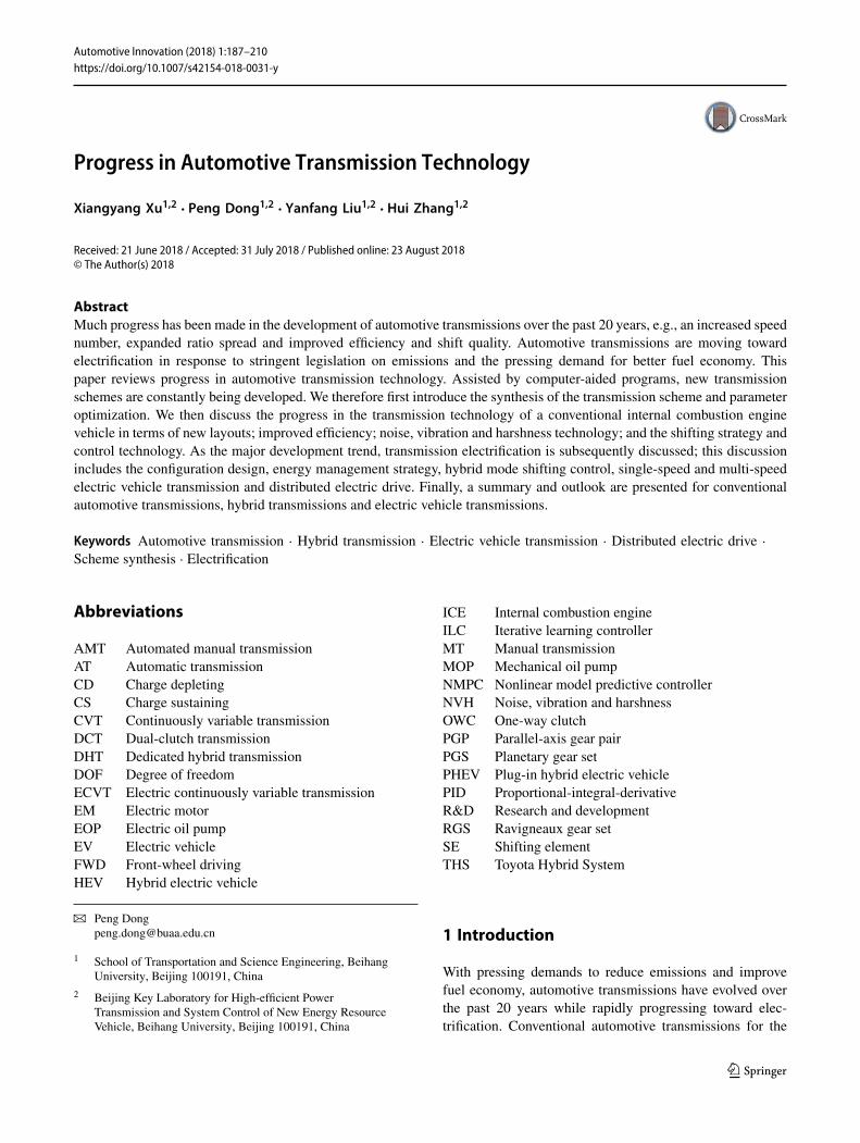
The benchmark synthesis method starts from a basic scheme,which can be selected from existing transmission schemeshaving good performance [2]. By adding or removing partialPGSs andSEsor tuning the stationary ratio of PGSs andPGPs[3], a new transmission scheme is extended from the basicscheme. Dong synthesized a 13-speed AT scheme based onan eight-speed AT scheme by adding one SE [4], as shownin Fig. 1. A 9-, 11- or 13-speed clutching sequence can berealized by tuning the stationary ratios of PGPs.
The method requires little calculation effort to facilitatemanual operation. However, it relies heavily on the experi-ence of the designer and the features of the selected basicscheme. Therefore, the final solution is usually not a globaloptimal solution.
123
Progress in Automotive Transmission Technology 189
C5
1st axis
2nd axis
Input
Output Output
C1C3B1C4
C2
1
2
11
5
8
4
7
6
10
3
9
PGS1
PGS2
PGS3
PGP1PGP2PGP3
0
Housing
Final driveFD
1st axis
2nd axis
Input
Output Output
C1C3B1C4
C2
1
2
11
5
8
4
7
6
10
3
9
PGS1
PGS2
PGS3
PGP1PGP2PGP3
0
Housing
Final driveFD
8AT 13AT
Fig. 1 Transmission schemes of eight-speed and 13-speed ATs. (Reproduced with permission from [4])
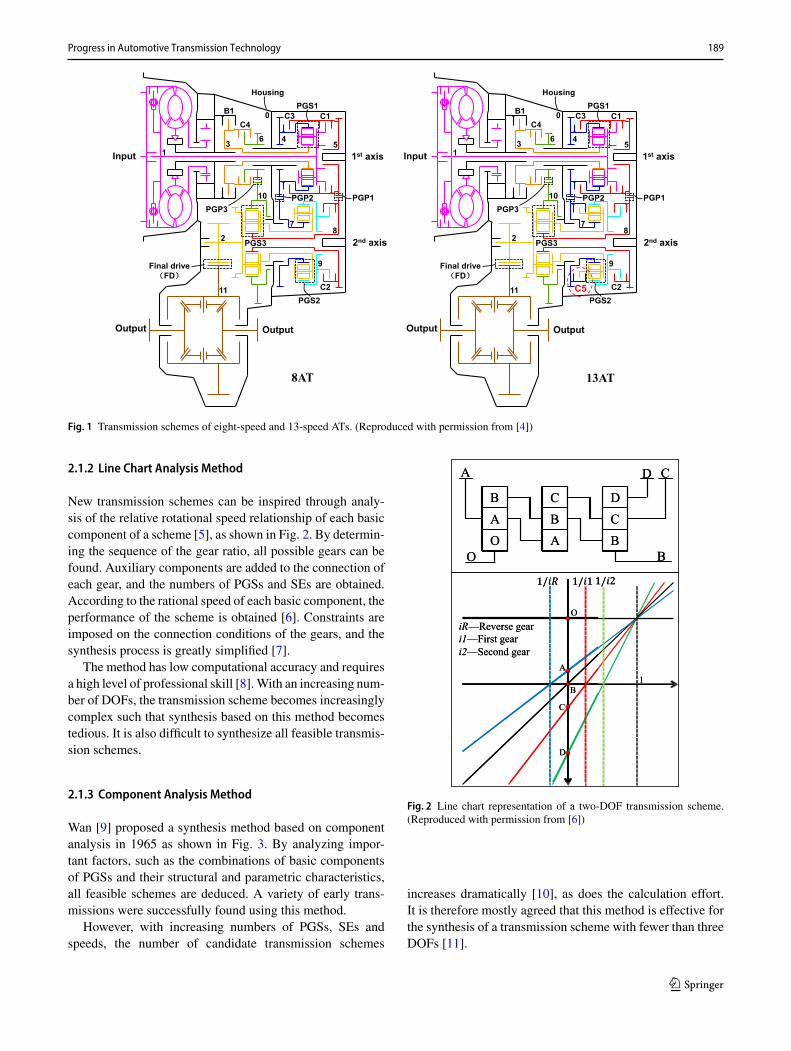
2.1.2 Line Chart Analysis Method
New transmission schemes can be inspired through analy-sis of the relative rotational speed relationship of each basiccomponent of a scheme [5], as shown in Fig. 2. By determin-ing the sequence of the gear ratio, all possible gears can befound. Auxiliary components are added to the connection ofeach gear, and the numbers of PGSs and SEs are obtained.According to the rational speed of each basic component, theperformance of the scheme is obtained [6]. Constraints areimposed on the connection conditions of the gears, and thesynthesis process is greatly simplified [7].
The method has low computational accuracy and requiresa high level of professional skill [8].With an increasing num-ber of DOFs, the transmission scheme becomes increasinglycomplex such that synthesis based on this method becomestedious. It is also difficult to synthesize all feasible transmis-sion schemes.
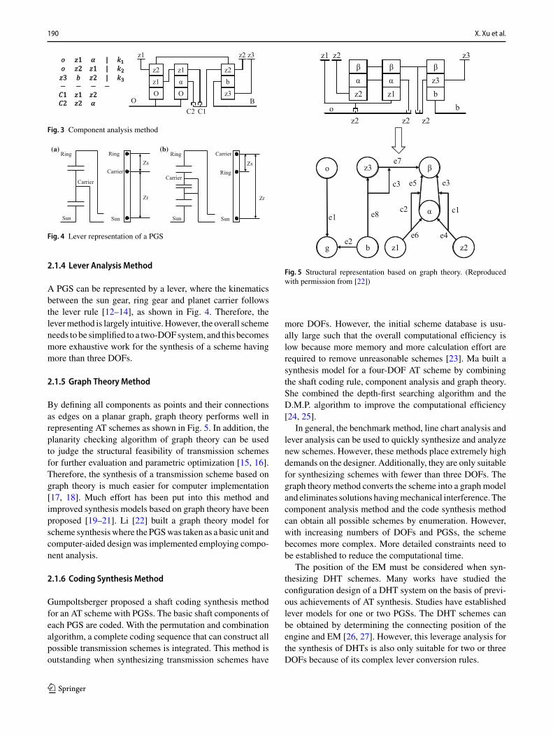
2.1.3 Component Analysis Method
Wan [9] proposed a synthesis method based on componentanalysis in 1965 as shown in Fig. 3. By analyzing impor-tant factors, such as the combinations of basic componentsof PGSs and their structural and parametric characteristics,all feasible schemes are deduced. A variety of early trans-missions were successfully found using this method.
However, with increasing numbers of PGSs, SEs andspeeds, the number of candidate transmission schemes
OAB
ABC
BCD
O B
A CD
OAB
ABC
BCD
O B
A CD
O
B
A
C
D
1/ 1/1/
1
iR—Reverse geari1—First geari2—Second gear
O
B
A
C
D
1/ 1/1/
1
iR—Reverse geari1—First geari2—Second gear
Fig. 2 Line chart representation of a two-DOF transmission scheme.(Reproduced with permission from [6])
increases dramatically [10], as does the calculation effort.It is therefore mostly agreed that this method is effective forthe synthesis of a transmission scheme with fewer than threeDOFs [11].
123
190 X. Xu et al.
Oz1z2
Oαz1
z3bz2
z1 z3z2
O BC1C2
Fig. 3 Component analysis method
Sun Sun
Carrier
Carrier
Ring RingZs
Zr
Sun
Carrier
Ring
Sun
Carrier
RingZs
Zr
(a) (b)
Fig. 4 Lever representation of a PGS
2.1.4 Lever Analysis Method
A PGS can be represented by a lever, where the kinematicsbetween the sun gear, ring gear and planet carrier followsthe lever rule [12–14], as shown in Fig. 4. Therefore, thelevermethod is largely intuitive.However, the overall schemeneeds to be simplified to a two-DOFsystem, and this becomesmore exhaustive work for the synthesis of a scheme havingmore than three DOFs.
2.1.5 Graph Theory Method
By defining all components as points and their connectionsas edges on a planar graph, graph theory performs well inrepresenting AT schemes as shown in Fig. 5. In addition, theplanarity checking algorithm of graph theory can be usedto judge the structural feasibility of transmission schemesfor further evaluation and parametric optimization [15, 16].Therefore, the synthesis of a transmission scheme based ongraph theory is much easier for computer implementation[17, 18]. Much effort has been put into this method andimproved synthesis models based on graph theory have beenproposed [19–21]. Li [22] built a graph theory model forscheme synthesiswhere the PGSwas taken as a basic unit andcomputer-aided design was implemented employing compo-nent analysis.
2.1.6 Coding Synthesis Method
Gumpoltsberger proposed a shaft coding synthesis methodfor an AT scheme with PGSs. The basic shaft components ofeach PGS are coded. With the permutation and combinationalgorithm, a complete coding sequence that can construct allpossible transmission schemes is integrated. This method isoutstanding when synthesizing transmission schemes have
o
g z1 z2
z3
α
β
b
e1
e2
e8
c3
e7
e3e5
c2 c1
e6 e4
z2αβ
z1αβ
bz3β
z2z1 z3
o bz2 z2z2
Fig. 5 Structural representation based on graph theory. (Reproducedwith permission from [22])
more DOFs. However, the initial scheme database is usu-ally large such that the overall computational efficiency islow because more memory and more calculation effort arerequired to remove unreasonable schemes [23]. Ma built asynthesis model for a four-DOF AT scheme by combiningthe shaft coding rule, component analysis and graph theory.She combined the depth-first searching algorithm and theD.M.P. algorithm to improve the computational efficiency[24, 25].
In general, the benchmark method, line chart analysis andlever analysis can be used to quickly synthesize and analyzenew schemes. However, these methods place extremely highdemands on the designer. Additionally, they are only suitablefor synthesizing schemes with fewer than three DOFs. Thegraph theory method converts the scheme into a graph modeland eliminates solutions havingmechanical interference. Thecomponent analysis method and the code synthesis methodcan obtain all possible schemes by enumeration. However,with increasing numbers of DOFs and PGSs, the schemebecomes more complex. More detailed constraints need tobe established to reduce the computational time.
The position of the EM must be considered when syn-thesizing DHT schemes. Many works have studied theconfiguration design of a DHT system on the basis of previ-ous achievements of AT synthesis. Studies have establishedlever models for one or two PGSs. The DHT schemes canbe obtained by determining the connecting position of theengine and EM [26, 27]. However, this leverage analysis forthe synthesis of DHTs is also only suitable for two or threeDOFs because of its complex lever conversion rules.
123

Progress in Automotive Transmission Technology 191
Graph theory is also applied for the synthesis of DHTs[28–30]. A graph model of PGSs is first built. A certain num-ber of points are randomly selected as thefixed connections tothe energy resource. Clutch connections are then introducedinto the graph model. All design schemes are obtained bytraversing all points. Peng proposed a model-based designmethod to realize the above design process efficiently [28,31]. By analyzing the characteristics of each operating modeof DHT systems [32], different constraints are deduced andthe configuration schemes that meet the design requirementsare finally obtained [33–37]. Meanwhile, the correspondingcomputational algorithms for the structural design of DHTsystems have been discussed by taking the wheelset as thebasic topology unit in graph theory [38, 39]. Although adesign process and its computer-aided synthesis based ongraph theory have been employed, it remains necessary tofocus on how to find the best solution with multiple DOFsand high efficiency.
FEV proposed an integrated approach for synthesizingmulti-axial DCT schemes. By introducing the dual-clutchshaft into the power transmission path, a plurality of DCTschemes with n+x gears are synthesized, each having thesame structural dimensions as the originalDCTschemeswithn gears [40]. Leesch proposed a synthesis method for DCTschemes that involves traversing the power flow path [41].
In summary,many studies on the synthesis of transmissionschemes have been conducted. However, with the increasingnumbers of components and DOFs, the computational effi-ciency of synthesis is declining becausemore time is requiredfor the detection of mechanical interference and isomorphicschemes. Therefore, how to improve the versatility and effi-ciency of the synthesis algorithmwill be an ongoing researchhotspot.
2.2 Parameter Optimization
The performance of a transmission scheme in terms of, forexample, the gear ratios, mechanical efficiency and structuralcompactnesswill depend on design parameters. It is thereforeessential tofind theoptimal parameterswithwhich todesign atransmission scheme with good performance [42]. However,this is difficult because there are a great many parameters andmany optimization goals.
Most work nowadays focuses on the parametric optimiza-tion of the stationary ratios of PGSs. Ideal transmission ratiosfor all gears are usually given in advance by experienced engi-neers as the initial optimization target. The transmission ratioof each gear is determined by the stationary ratios of PGSs.Some numerical algorithms, such as dynamic programming,ant colony, particle swarm and genetic algorithms, have beenshown to be effective for solving such problems [4, 43].
There remain strict requirements in addition to the trans-mission ratios [44] in the parametric design of a transmission
scheme.However, the computational effort increases dramat-ically once these are taken into account. For conventionalATs, how to build a parametric optimization model consid-ering as many factors as possible will be another ongoingresearch hotspot. Chen proposed an improved minimum andmaximum principle to optimize the detailed gear param-eters (including the gear modulus, gear teeth number andgear width) of a two-speed transmission scheme and built anoptimization model for the optimal dynamic and economicperformance [45, 46]. For DHTs in HEVs and PHEVs, themain focus is energy management and mode shifting control[47]. However, the coordination of multiple power sourcesis also an important factor, and few published works havefocused on structural parametric optimization design.
3 Progress in the Transmission Technologyof a Conventional ICE Vehicle
This section gives a general review of the latest develop-ments of conventional automotive transmission for the ICE.The transmission layout synthesis, efficiency improvement,noise, vibration and harshness (NVH) technology, shiftingstrategy and control technology are discussed separately.
3.1 Transmission Layout Synthesis
Novel AT and DCT schemes have continuously emergedin recent years with an increasing number of speeds. Agrowing number of automakers are introducing these novelmulti-speed transmissions to their vehicles, as a part of acontinuing effort to improve the drivability and fuel econ-omy of their vehicles. On the one hand, the highest gearratio has been decreased to improve fuel economy when avehicle is cruising. On the other hand, the lowest gear ratiohas been increased to improve drivability when a vehicle islaunching or creeping. The increasing speed number allowsfor smaller gear steps that provide comfort and smooth shifts.CVT schemes have not changed greatly. Themain type is stillthe chain or belt drive. Jatco integrated an auxiliary gearboxwith oneRavigneaux gear set (RGS) and three SEs to achievea wider ratio spread [48]. Other CVT concepts, such as thetoroidal variator, are still far from industrialization.
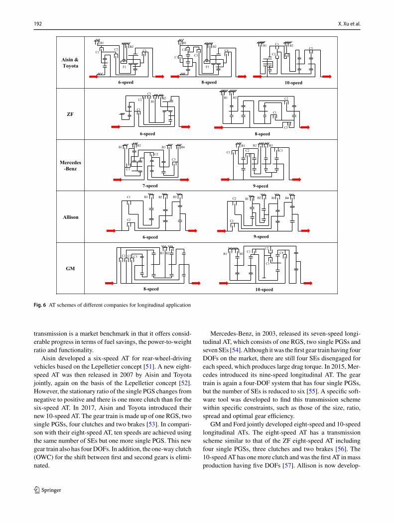
3.1.1 AT Schemes
Figure 6 shows AT schemes of different companies for lon-gitudinal application. In 2001, ZF launched its six-speed ATbased on the Lepelletier concept with one single PGS, oneRGSandfiveSEs [49]. In 2007,ZF introduced its eight-speedAT with four PGSs and five SEs instead of the Lepelletier-based structure [50]. The system has four DOFs, whichmeans three SEs need to be engaged for each speed. This
123
192 X. Xu et al.
Aisin & Toyota
ZF
Mercedes-Benz
Allison
GM
6-speed 8-speed 10-speed
B1B2
C1C2 C3
F1
C3
B1B2
C1
C2 C4
F1
C1
C2
C3B1 B2
6-speed 8-speed
C1
C2
C3
B1B2
C1
C2
C3
B1 B2
7-speed 9-speed
C1
C2C3
B1 B2 B3 B4C1 C2 C3
B1 B2 B3
6-speed 9-speed
C1 B1 B2 B3
C2 C1
B1 B2 B3 B4C2
8-speed 10-speed
C1 C4
C3
C2
B1 B2C3C2C1
B2B1
Fig. 6 AT schemes of different companies for longitudinal application
transmission is a market benchmark in that it offers consid-erable progress in terms of fuel savings, the power-to-weightratio and functionality.
Aisin developed a six-speed AT for rear-wheel-drivingvehicles based on the Lepelletier concept [51]. A new eight-speed AT was then released in 2007 by Aisin and Toyotajointly, again on the basis of the Lepelletier concept [52].However, the stationary ratio of the single PGS changes fromnegative to positive and there is one more clutch than for thesix-speed AT. In 2017, Aisin and Toyota introduced theirnew 10-speed AT. The gear train is made up of one RGS, twosingle PGSs, four clutches and two brakes [53]. In compari-son with their eight-speed AT, ten speeds are achieved usingthe same number of SEs but one more single PGS. This newgear train also has fourDOFs. In addition, the one-way clutch(OWC) for the shift between first and second gears is elimi-nated.
Mercedes-Benz, in 2003, released its seven-speed longi-tudinal AT, which consists of one RGS, two single PGSs andsevenSEs [54].Although itwas thefirst gear train having fourDOFs on the market, there are still four SEs disengaged foreach speed, which produces large drag torque. In 2015, Mer-cedes introduced its nine-speed longitudinal AT. The geartrain is again a four-DOF system that has four single PGSs,but the number of SEs is reduced to six [55]. A specific soft-ware tool was developed to find this transmission schemewithin specific constraints, such as those of the size, ratio,spread and optimal gear efficiency.
GM and Ford jointly developed eight-speed and 10-speedlongitudinal ATs. The eight-speed AT has a transmissionscheme similar to that of the ZF eight-speed AT includingfour single PGSs, three clutches and two brakes [56]. The10-speedAT has onemore clutch andwas the first AT inmassproduction having five DOFs [57]. Allison is now develop-
123
Progress in Automotive Transmission Technology 193
ZF
Honda
Aisin
GM
Ford
9-speed
C1
B1B2
C2
6-speed 8-speed
C1
B2F1
C3C2
B1 C1
C2
C3B1
B2
8F24 8F35 8F57
C1B1
B2B3 B4
C2C1
B1 B2B3
B4
C2
9-speed6-speed
10-speed
C1
C2
B1 B2B3
S1
C1C2
C3
S1B1
B2 B3
C1
C2
B1 B2 B3
F1C1
C2
C3
S1B1B2
B3
Fig. 7 AT schemes of different companies for front-transverse application
ing a nine-speed AT for the medium-duty commercial truckmarket [58]. An additional PGS and brake have been addedon the basis of Allison’s proven reliable six-speed AT. Thenew gear train features four PGSs and six SEs. Prototypesare being tested internally.
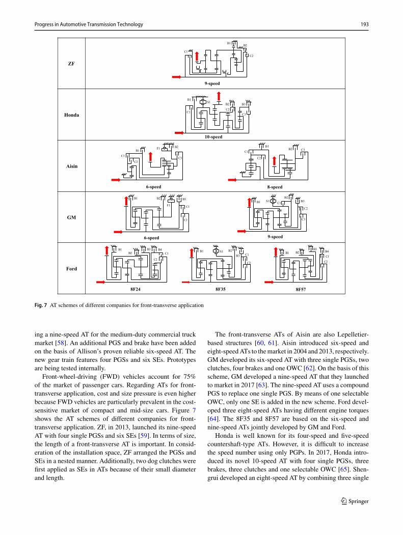
Front-wheel-driving (FWD) vehicles account for 75%of the market of passenger cars. Regarding ATs for front-transverse application, cost and size pressure is even higherbecause FWD vehicles are particularly prevalent in the cost-sensitive market of compact and mid-size cars. Figure 7shows the AT schemes of different companies for front-transverse application. ZF, in 2013, launched its nine-speedAT with four single PGSs and six SEs [59]. In terms of size,the length of a front-transverse AT is important. In consid-eration of the installation space, ZF arranged the PGSs andSEs in a nested manner. Additionally, two dog clutches werefirst applied as SEs in ATs because of their small diameterand length.
The front-transverse ATs of Aisin are also Lepelletier-based structures [60, 61]. Aisin introduced six-speed andeight-speedATs to themarket in 2004 and 2013, respectively.GM developed its six-speed AT with three single PGSs, twoclutches, four brakes and one OWC [62]. On the basis of thisscheme, GM developed a nine-speed AT that they launchedto market in 2017 [63]. The nine-speed AT uses a compoundPGS to replace one single PGS. By means of one selectableOWC, only one SE is added in the new scheme. Ford devel-oped three eight-speed ATs having different engine torques[64]. The 8F35 and 8F57 are based on the six-speed andnine-speed ATs jointly developed by GM and Ford.
Honda is well known for its four-speed and five-speedcountershaft-type ATs. However, it is difficult to increasethe speed number using only PGPs. In 2017, Honda intro-duced its novel 10-speed AT with four single PGSs, threebrakes, three clutches and one selectable OWC [65]. Shen-grui developed an eight-speed AT by combining three single
123

194 X. Xu et al.
Volkswagen 7-speed Volkswagen 6-speed Volkswagen 7-speed
12 34
56 7
R
132 4
56R 1R
2 3
4 5
6 7
Great Wall Motor 7-speed Honda 8-speed GETRAG 7-speed
R
12
34 5
6 7
1
2
3
4
5
6
7
8
R154R
3762
Fig. 8 DCT schemes of different companies
PGSs, three PGPs and five SEs on two parallel axes [66].A nine, eleven or thirteen-speed clutching sequence can berealized by adding one clutch and tuning the stationary ratioof the three PGPs [4].
3.1.2 DCT Schemes
DCTs combine the advantage of MTs (i.e., high efficiency)with that of ATs (i.e., power shifts). Owing to the lack ofa torque converter, DCTs require a higher first gear ratio tolaunch the vehicle.
Figure 8 presents several DCT schemes that are in massproduction. The first DCT for passenger cars, DQ250 fromVolkswagen (VW), went into serial production in 2003 [67].A wet multi-plate dual-clutch module from BorgWarner isapplied to divide the gears into odd gears and even gears.An advantage of DCT over AT is that only one disengagedclutch causes drag losses. In 2007, VW introduced its seven-speed DCT with a dry dual-clutch module from LuK [68].Compared with DQ250, DQ200 has higher efficiency butlower torque capacity. DQ500 came onto the market in 2009[69] and is a seven-speed DCT with a wet multi-plate dual-clutchmodule.VWuses thisDCT in larger and higher-outputvehicles.
The success of the VW DCT sets a benchmark in termsof the shift speed, sports performance and efficiency. Other
vehicle or transmission manufacturers, such as GETRAG,Great Wall and Geely, have started developing their ownDCTs. Honda released its eight-speed DCT in 2014 with anultra-flat torque converter, the adoption of which helps vehi-cles launch powerfully and smoothly. Additionally, insteadof the integrated dual-clutch module in conventional DCT,the dual clutch is separately arranged on parallel shafts toreduce inertia [70].
DCTs are mainly applied for FWD vehicles. To achievemore speeds, DCTs must have more PGPs, synchronizersand forks. However, this is difficult to realize within the lim-ited space of the engine compartment. Therefore, the speednumber of DCTs is currently less than that of ATs. It hasbeen reported that VWwas once developing a 10-speed DCTadopting the winding gear concept but this effort has sincebeen terminated.
3.2 Efficiency Improvement
Transmissions have tended to have more speeds in recentyears because of legislative pressure relating to CO2 reduc-tions and fuel economy. However, driving simulations indi-cate that increasing the speed number beyond 10 will notimprove the fuel economy appreciably [71]. Different opti-mization approaches have therefore been investigated for
123
Progress in Automotive Transmission Technology 195
Type of return springs
Multi-coil spring pack
Slotted disc spring
Separating spring
Drag torque reduction No No Yes
Graphic
Installation space
Fig. 9 Different types of return spring. (Reproduced with permissionfrom [72])
mechanical and hydraulic systems to improve transmissionefficiency.
3.2.1 Mechanical System
The transmission scheme is important in terms of improv-ing the efficiency of a mechanical system. Newly developedATs usually have four or even five DOFs instead of threeDOFs because it means that fewer SEs are disengaged foreach speed, resulting in small drag losses. Optimizationsregarding friction loss and drag torque loss are continuouslyin progress on the component level. Low-friction bearings,seals and damper systems have gradually become popular inATs, DCTs and CVTs, contributing greatly to improvementsin efficiency.
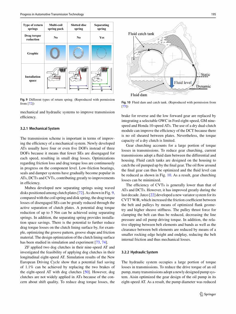
Mubea developed new separating springs using waveddisks positioned among clutch plates [72].As shown inFig. 9,comparedwith the coil spring and disk spring, the drag torquelosses of disengaged SEs can be greatly reduced through theactive separation of clutch plates. A potential drag torquereduction of up to 5 Nm can be achieved using separatingsprings. In addition, the separating spring provides installa-tion space savings. There is the potential to further reducedrag torque losses on the clutch lining surface by, for exam-ple, optimizing the groove pattern, groove shape and frictionmaterial. The design optimization of the clutch lining surfacehas been studied in simulation and experiment [73, 74].
ZF applied two dog clutches in their nine-speed AT andinvestigated the feasibility of applying dog clutches in theirlongitudinal eight-speed AT. Simulation results of the NewEuropean Driving Cycle show that a potential fuel savingof 1.1% can be achieved by replacing the two brakes ofthe eight-speed AT with dog clutches [50]. However, dogclutches are not widely applied in ATs because of the con-cern about shift quality. To reduce drag torque losses, the
Fig. 10 Fluid dam and catch tank. (Reproduced with permission from[75])
brake for reverse and the low forward gear are replaced byintegrating a selectable OWC in Ford eight-speed, GM nine-speed and Honda 10-speed ATs. The use of a dry dual-clutchmodule can improve the efficiency of the DCT because thereis no oil sheared between plates. Nevertheless, the torquecapacity of a dry clutch is limited.
Gear churching accounts for a large portion of torquelosses in transmissions. To reduce gear churching, currenttransmissions adopt a fluid dam between the differential andhousing. Fluid catch tanks are designed on the housing tocatch the oil pumped up by the final gear. The oil flow aroundthe final gear can thus be optimized and the fluid level canbe reduced as shown in Fig. 10. As a result, gear churchinglosses can be minimized.
The efficiency of CVTs is generally lower than that ofATs and DCTs. However, it has improved greatly during thelast decade. Jatco [22] developed a newvariator system for itsCVT7W/R, which increased the friction coefficient betweenthe belt and pulleys by means of optimized flank geome-try and higher sheave stiffness. The pulley thrust force forclamping the belt can thus be reduced, decreasing the linepressure and oil pump driving torque. In addition, the rela-tive slipping between belt elements and bands as well as theclearance between belt elements are reduced by means of asmaller rocking edge height and endplay, reducing the beltinternal friction and thus mechanical losses.
3.2.2 Hydraulic System
The hydraulic system occupies a large portion of torquelosses in transmissions. To reduce the drive torque of an oilpump,many transmissions adopt a newly designed pump sys-tem. Aisin optimized the gear design of the oil pump in itseight-speed AT. As a result, the pump diameter was reduced
123
196 X. Xu et al.
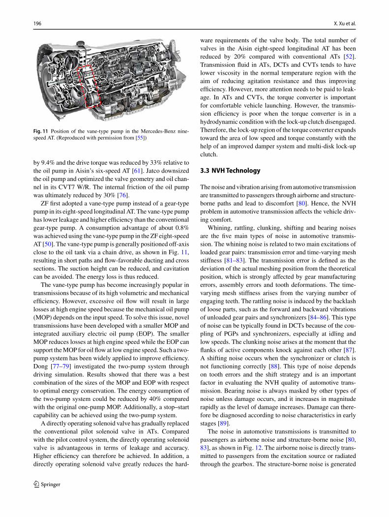
Fig. 11 Position of the vane-type pump in the Mercedes-Benz nine-speed AT. (Reproduced with permission from [55])
by 9.4% and the drive torque was reduced by 33% relative tothe oil pump in Aisin’s six-speed AT [61]. Jatco downsizedthe oil pump and optimized the valve geometry and oil chan-nel in its CVT7 W/R. The internal friction of the oil pumpwas ultimately reduced by 30% [76].
ZF first adopted a vane-type pump instead of a gear-typepump in its eight-speed longitudinal AT. The vane-type pumphas lower leakage and higher efficiency than the conventionalgear-type pump. A consumption advantage of about 0.8%was achieved using the vane-type pump in the ZF eight-speedAT [50]. The vane-type pump is generally positioned off-axisclose to the oil tank via a chain drive, as shown in Fig. 11,resulting in short paths and flow-favorable ducting and crosssections. The suction height can be reduced, and cavitationcan be avoided. The energy loss is thus reduced.
The vane-type pump has become increasingly popular intransmissions because of its high volumetric and mechanicalefficiency. However, excessive oil flow will result in largelosses at high engine speed because the mechanical oil pump(MOP) depends on the input speed. To solve this issue, noveltransmissions have been developed with a smaller MOP andintegrated auxiliary electric oil pump (EOP). The smallerMOP reduces losses at high engine speed while the EOP cansupport theMOP for oil flow at low engine speed. Such a two-pump system has been widely applied to improve efficiency.Dong [77–79] investigated the two-pump system throughdriving simulation. Results showed that there was a bestcombination of the sizes of the MOP and EOP with respectto optimal energy conservation. The energy consumption ofthe two-pump system could be reduced by 40% comparedwith the original one-pump MOP. Additionally, a stop–startcapability can be achieved using the two-pump system.
A directly operating solenoid valve has gradually replacedthe conventional pilot solenoid valve in ATs. Comparedwith the pilot control system, the directly operating solenoidvalve is advantageous in terms of leakage and accuracy.Higher efficiency can therefore be achieved. In addition, adirectly operating solenoid valve greatly reduces the hard-
ware requirements of the valve body. The total number ofvalves in the Aisin eight-speed longitudinal AT has beenreduced by 20% compared with conventional ATs [52].Transmission fluid in ATs, DCTs and CVTs tends to havelower viscosity in the normal temperature region with theaim of reducing agitation resistance and thus improvingefficiency. However, more attention needs to be paid to leak-age. In ATs and CVTs, the torque converter is importantfor comfortable vehicle launching. However, the transmis-sion efficiency is poor when the torque converter is in ahydrodynamic condition with the lock-up clutch disengaged.Therefore, the lock-up region of the torque converter expandstoward the area of low speed and torque constantly with thehelp of an improved damper system and multi-disk lock-upclutch.
3.3 NVHTechnology
Thenoise andvibration arising fromautomotive transmissionare transmitted to passengers through airborne and structure-borne paths and lead to discomfort [80]. Hence, the NVHproblem in automotive transmission affects the vehicle driv-ing comfort.
Whining, rattling, clunking, shifting and bearing noisesare the five main types of noise in automotive transmis-sion. The whining noise is related to two main excitations ofloaded gear pairs: transmission error and time-varying meshstiffness [81–83]. The transmission error is defined as thedeviation of the actual meshing position from the theoreticalposition, which is strongly affected by gear manufacturingerrors, assembly errors and tooth deformations. The time-varying mesh stiffness arises from the varying number ofengaging teeth. The rattling noise is induced by the backlashof loose parts, such as the forward and backward vibrationsof unloaded gear pairs and synchronizers [84–86]. This typeof noise can be typically found in DCTs because of the cou-pling of PGPs and synchronizers, especially at idling andlow speeds. The clunking noise arises at the moment that theflanks of active components knock against each other [87].A shifting noise occurs when the synchronizer or clutch isnot functioning correctly [88]. This type of noise dependson tooth errors and the shift strategy and is an importantfactor in evaluating the NVH quality of automotive trans-mission. Bearing noise is always masked by other types ofnoise unless damage occurs, and it increases in magnituderapidly as the level of damage increases. Damage can there-fore be diagnosed according to noise characteristics in earlystages [89].
The noise in automotive transmissions is transmitted topassengers as airborne noise and structure-borne noise [80,83], as shown in Fig. 12. The airborne noise is directly trans-mitted to passengers from the excitation source or radiatedthrough the gearbox. The structure-borne noise is generated
123

Progress in Automotive Transmission Technology 197
Source Path Gearbox
Car bodyPassenger
Airborne noise
Structure-borne noise
Fig. 12 Passage of airborne and structure-borne noise
by an excitation source and transmitted to passengers throughthe shafts, bearings, mountings and car body.
Active and passive measures are often adopted to improvethe NVH quality of automotive transmissions. Active mea-sures are mainly concentrated on addressing noise sources.A high-contact ratio gear, helical gear, modified tooth profileand high-quality tooth surface can reduce the gear whiningnoise [83, 90]. Minimizing the backlash and the inertia ofloose parts, optimizing the synchronizer design and reduc-ing torsional vibration from the ICE can help reduce therattling noise [91]. Furthermore, a torsional damper, dualmass flywheel or pendulum absorber is often placed betweenthe engine and transmission to reduce vibration and fluc-tuation from the ICE and thus effectively suppress therattling noise and vibration of the gearbox. Passive mea-sures relate to transmission routes of structure-borne noisefrom the noise source to the car body. Examples of pas-sive measures include increasing the stiffness of gear bodies,shafts, bearings and housings and separating the natural fre-quencies of these components and tuning the transmissionmounting [92].
3.4 Shifting Strategy and Control Technology
Thebiggest complaint of customers relating toATs andDCTsrelates to the shift quality. The control of the shifting processis therefore important. Transmission manufacturers improveshift quality through both hardware and software develop-ment. In terms of hardware development, a directly operatingsolenoid valve is used in novel ATs and DCTs to improve thecontrol accuracy. A torque converter with a flat and small-diameter torus and a clutch hubwith high-strength aluminumare applied in theAisin 10-speed longitudinal AT [53], whichreduces rotational inertia to realize a short shifting time. Thepiston chamber volume of each SE is also reduced to prevent
a long shift response due to piston or cylinder movement inclutch engagement.
In terms of software development, numerous studies haveinvestigated shifting strategies and control technologies. Theshifts in ATs and DCTs are clutch-to-clutch shifts with-out power interruption. During torque transference from theoff-going clutch to the on-coming clutch and speed synchro-nization from the current gear to the target gear, drivers expecta fast and smooth transitionwithout drivetrain jerking, result-ing in a demand for a high-quality shift.
The two primary challenges for wet-clutch control are (i)the intrinsically complex and nonlinear behavior [93] and (ii)the diversification of the dynamics over time due to changesin load, oil temperature and wear [94]. Studies [95–97] havefocused on developing dynamic models of automotive trans-missions in the shifting process. Relevant studies have alsoconcentrated on different control approaches using a learn-ing algorithm in the clutch control system. For instance, thetwo-level nonlinear model predictive controller (NMPC) anditerative learning controller (ILC) forwet-clutch control havebeen compared [98]. Meanwhile, the potential of severalmodel-based (i.e., NMPC, ILC and iterative optimization)and model-free (i.e., genetic-based machine learning andreinforcement learning) learning strategies have been ana-lyzed for the control of wet clutches [99].
There are generally three phases in clutch-to-clutch shifts:the fill phase, torque phase and inertia phase [100–102]. Theclutch fill control is affected by many factors, such as char-acteristics of the clutch actuation system, oil temperatureand engine speed [103]. Inaccurate clutch fill control canresult in either an under-fill or an over-fill [104, 105]. It isnecessary to implement methodologies in clutch fill control.Clutch fill control was improved to some extent using a newcustomized numerical dynamic programming method withpressure sensors [106]. An adaptive sliding mode observerhas been implemented [107] to improve the online estima-tion of the turbine torque and hence improve the accuracy ofthe clutch pressure estimation in the fill phase.
In terms of control strategies for the torque phase, modelsand algorithms have been proposed according to the dynamiccharacteristics of the clutch-to-clutch shift. Control strategiesfor upshifts and downshifts have been proposed, and a clutchtorque controller has been designed for the torque phase onthe basis of the proportional-integral-derivative (PID) con-trol algorithm [108]. A simple and robust controller design,which is based on the actuator dynamics and the clutch slipdynamics and has consistent performance under different ini-tial conditions, has been presented [109].
In terms of control strategies for the inertia phase, acombination of sliding mode control and adaptive feedbacklinearization has been used to achieve the desired referencetracking for the slip of the on-coming clutch [110]. A model-based nonlinear gearshift controller was designed employing
123

198 X. Xu et al.
the back-stepping method to improve the shift quality ofvehicleswithDCTduring the inertia phase [111]. A newnon-linear control method, especially applied in the inertia phase,was developed to deal directly with model parameter varia-tion. It can be designed using a method involving three steps:steady-state control, reference dynamics feedforward controland PID feedback control [112]. The coordinated control ofthe engine and transmission has greatly improved the shiftquality and clutch durability. This method is widely appliedfor the inertia phase of clutch-to-clutch shifts.
To compensate for the effects of build-to-build and life-cycle variations on shift quality, it is necessary to use adaptivecontrol methods in shift control strategies. An adaptive sys-tem not only continuously monitors its own performance inrelation to a given optimal condition but also modifies itsown control parameters in a closed loop so as to approach theoptimized performance. It has been experimentally demon-strated that clutch adaptive control strategies for the dry DCTnot only reduce the level of jerk and frictional energy loss butalso satisfy different starting intentions of the driver [113].Kim [114] proposed an advanced shift controller that super-vises the shift transients with adaptive compensation. Thecontrol input is updated through a learning process to adjustsubsequent shifts on the basis of the continuous monitoringof shift performance and environment variations. Shi [115]proposed adaptive control strategies for the inertia phaseand torque phase. Shift quality is evaluated by monitoringthe speed deviation and time difference. Test results verifythat the proposed control strategies improve the shift qualityeffectively.
DCT sets a benchmark for the shift time, giving the drivera quick response to the acceleration requirement. Controlstrategies have been developed for CVTs and ATs to com-pete with DCTs in terms of a shorter shift time. Jatco [116]used stepwise shift control to improve the acceleration feel-ing of CVT. BMW proposed control strategies for complexshift events to cover situations where the target gear is nor-mally reached by passing through intermediate gear steps[117]. Through simultaneous actuation of various SEs, twosequential shifts are executed continuously. The overall shiftduration can thus be reduced to achieve a fast shift perfor-mance. Aisin announced that its 10-speed longitudinal AThas a faster shift than the benchmarked AT and DCT [53].
4 Electrified Transmission Technologyfor HEVs/PHEVs/EVs
This section reviews the progress of automotive trans-missions for HEVs/PHEVs/EVs. The configuration design,energy management strategy, hybrid mode shifting control,EV transmission and distributed-drive EV are discussed sep-arately.
4.1 Configuration Design
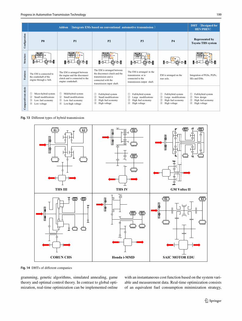
HEVs and PHEVs generally have one ICE and one or twoEMs. Although the battery capacity differs between HEVsand PHEVs, the structural requirements for the drive sys-tem are the same. As previously described, HEV and PHEVtransmissions can be simply divided into two types, namelyadd-on transmissions and DHTs [118], as shown in Fig. 13.
On the basis of conventional automotive transmissions,many manufacturers have developed a variety of hybrid con-figurations. ZF, Mercedes-Benz and Hyundai introduced P2systems based on their own mature ATs. Jatco and Cherydeveloped P2 systems based on CVTs. VW proposed a P2hybrid system based on its own DCT. BYD also proposed ahybrid system based on DCT, but this is a P3 configuration.
Unlike the add-on solution, the DHT breaks the structuralconstraints of conventional transmissions. As the earliestDHT, the Toyota Hybrid System (THS) provided the direc-tion for subsequent development in configuration design[119]. As technology advanced, Toyota introduced a fourth-generation hybrid system, as shown in Fig. 14, and thissystem is nowwidely applied [120].GMproposed twohybridsystems, namely Voltec-I and Voltec-II [121]. The second-generation system Voltec-II is shown in Fig. 14 and is usedfor the Volt, Malibu and Cadillac CT6. Compared with theTHS,Voltec-II hasmore operatingmodes butmore PGSs andSEs. Corun developed a hybrid system with multiple modesusing an RGS and two SEs [122], as shown in Fig. 14. Theabove schemes are based on PGSs. In addition, companiessuch as Honda and SAIC have developed DHTs based onPGPs as shown in Fig. 14 [123, 124].
4.2 EnergyManagement Strategy
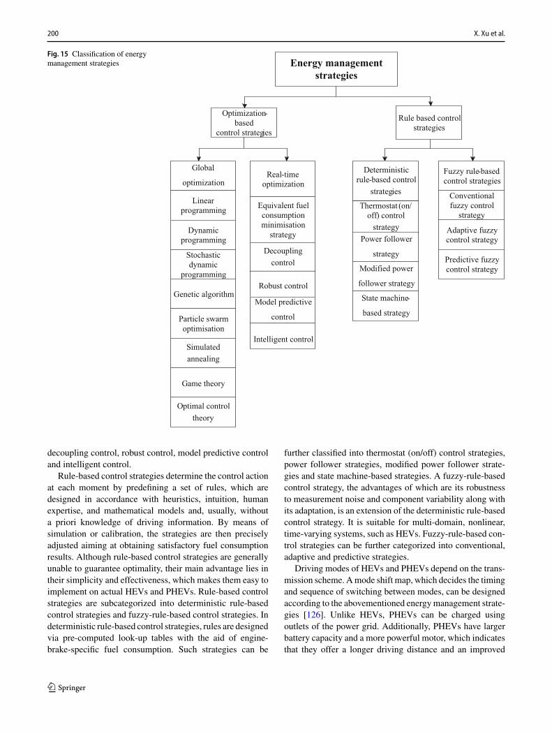
Energy management strategies for HEVs and PHEVs havebeen extensively discussed in the literature over the lastdecade. Figure 15 shows that energy management strategiescan be generally classified into optimization-based controlstrategies and rule-based control strategies [125].
Optimization-based control strategies use analytical ornumerical optimization algorithms to minimize the costfunction regarding fuel consumption, emissions or drivingperformance. Optimization-based control strategies can bedivided into global optimization and real-time optimization.If the optimization relies on knowledge of past or futurepower demands over a fixed and known driving cycle, aglobal optimal solution can be found. Because global opti-mization cannot be implemented directly for real-time energymanagement, it is referred to as non-causal. However, globaloptimization is useful in providing a control benchmark fordesigning rules or comparing with other control strategies.The strategies categorized under global optimization includelinear programming, stochastic programming, dynamic pro-
123
Progress in Automotive Transmission Technology 199
Add-on (Integrate EMs based on conventional automotive transmission ) DHT(Designed for HEV/PHEV)
Con
figur
atio
n
P0 P1 P2 P3 P4 Represented by Toyota THS system
Stru
ctur
eFe
atur
es
The EM is connected to the crankshaft of the engine through a belt.
The EM is arranged between the engine and the disconnect clutch and is connected to the engine crankshaft.
The EM is arranged between the disconnect clutch and the transmission and is connected with the transmission input shaft.
The EM is arranged in the transmission or is connected to the transmission output shaft.
EM is arranged on the rear axle.
Integration of PGSs, PGPs, SEs and EMs.
Com
para
tivea
n al
ysis
① Micro-hybrid system② Small modifications③ Low fuel economy④ Low voltage
① Mild-hybrid system② Small modifications③ Low fuel economy④ Low/high voltage
① Full-hybrid system② Small modifications ③ High fuel economy ④ High voltage
① Full-hybrid system② Large modifications ③ High fuel economy ④ High voltage
① Full-hybrid system② Large modifications ③ High fuel economy ④ High voltage
① Full-hybrid system② New design③ High fuel economy ④ High voltage
Fig. 13 Different types of hybrid transmission
CORUN CHS Honda i-MMD
THS III THS IV
SAIC MOTOR EDU
GM Voltec II
Fig. 14 DHTs of different companies
gramming, genetic algorithms, simulated annealing, gametheory and optimal control theory. In contrast to global opti-mization, real-time optimization can be implemented online
with an instantaneous cost function based on the system vari-able and measurement data. Real-time optimization consistsof an equivalent fuel consumption minimization strategy,
123
200 X. Xu et al.
Fig. 15 Classification of energymanagement strategies Energy management
strategies
Linear programming
Dynamic programming
Stochastic dynamic
programming
Genetic algorithm
Particle swarm optimisation
Global
optimization
Simulated annealing
Game theory
Optimal control theory
Robust control
Equivalent fuel consumption minimisation
strategy
Decoupling control
Model predictive
control
Intelligent control
Real-time optimization
Fuzzy rule-based control strategies
Conventionalfuzzy control
strategy
Adaptive fuzzy control strategy
Predictive fuzzy control strategy
Rule based control strategies
Optimization-based
control strategies
Thermostat (on/off) control
strategy
State machine-
based strategy
Modified power
follower strategy
Power follower
strategy
Deterministic rule-based control
strategies
decoupling control, robust control, model predictive controland intelligent control.
Rule-based control strategies determine the control actionat each moment by predefining a set of rules, which aredesigned in accordance with heuristics, intuition, humanexpertise, and mathematical models and, usually, withouta priori knowledge of driving information. By means ofsimulation or calibration, the strategies are then preciselyadjusted aiming at obtaining satisfactory fuel consumptionresults. Although rule-based control strategies are generallyunable to guarantee optimality, their main advantage lies intheir simplicity and effectiveness, which makes them easy toimplement on actual HEVs and PHEVs. Rule-based controlstrategies are subcategorized into deterministic rule-basedcontrol strategies and fuzzy-rule-based control strategies. Indeterministic rule-based control strategies, rules are designedvia pre-computed look-up tables with the aid of engine-brake-specific fuel consumption. Such strategies can be
further classified into thermostat (on/off) control strategies,power follower strategies, modified power follower strate-gies and state machine-based strategies. A fuzzy-rule-basedcontrol strategy, the advantages of which are its robustnessto measurement noise and component variability along withits adaptation, is an extension of the deterministic rule-basedcontrol strategy. It is suitable for multi-domain, nonlinear,time-varying systems, such as HEVs. Fuzzy-rule-based con-trol strategies can be further categorized into conventional,adaptive and predictive strategies.
Driving modes of HEVs and PHEVs depend on the trans-mission scheme. Amode shift map, which decides the timingand sequence of switching between modes, can be designedaccording to the abovementioned energymanagement strate-gies [126]. Unlike HEVs, PHEVs can be charged usingoutlets of the power grid. Additionally, PHEVs have largerbattery capacity and a more powerful motor, which indicatesthat they offer a longer driving distance and an improved
123
Progress in Automotive Transmission Technology 201
driving ability in electric-only mode than HEVs. This hasgiven a new dimension to the energy management strategiesas PHEVs can operate in both charge depleting (CD) andcharge sustaining (CS) modes [127, 128]. Correspondingly,the transmission structure is modified for PHEV application;for example, an OWC is added to the THS to enable thevehicle to be driven using two motors [75].
4.3 Hybrid Mode Shifting Control
HEVs and PHEVs can run in different driving modes,among which typical modes are electric only, engine only,hybrid/electric assist, battery charging and regenerative brak-ing. Shifts are made among these driving modes accordingto the vehicle and road conditions. Similar to gear shifting inconventional automotive transmissions, the mode transitionin hybrid transmissions may result in negative customer per-ception of riding comfort and drivability if it is improperlycontrolled.
Engine start during mode transition is a major challengefor HEVs and PHEVs in terms of achieving good ridingcomfort. Some add-on hybrid transmissions retain a torqueconverter and improve their torsional damper to reducethe engine torque fluctuation from electric driving modeto hybrid driving mode. In control strategies, it is impor-tant to coordinate the engine torque, EM torque and clutchtorque properly and precisely. Xu [129] proposed differentengine-start control strategies with respect to riding com-fort or a quick response under different starting conditions.To realize the smooth and fast engine start of a P2 PHEV,Yang [130] proposed a hierarchical mode transition controlmethod based on a robust H∞ controller. Chen [131] devel-oped a model reference controller with which to coordinatethe engine, EM and clutch torque during mode transitionfor a series–parallel HEV. Zhao [132] developed a multi-stage optimal control strategy to determine the engine torqueand clutch torque during mode transition. Therein, a slidingmode controller with anti-interference ability was designedto control the engine speed following the reference trajec-tory. Additionally, the model used to calculate feedforwardcontrol and H∞ robust feedback control was applied in theclutch synchronization phase. Kum [133] investigated theo-retical performance limits and corresponding optimal controlstrategies that achieve a trade-off between drivability anda quick engine start. The results indicate that the optimalengine-start control strategy should choose a proper torquereserve and a corresponding clutch pressure that balancesthe engine-start time and torque responsiveness dependingon the vehicle state and driver input.
It is noted that the engine-start performance of P2 hybridtransmission depends on the control of the disconnect clutch.Because the EM can provide a rapid torque response, it isprecisely adjusted for both torque compensation and vehi-
DT
M
MT
MT
M
M
D T M
(a) (b)
(c) (d)
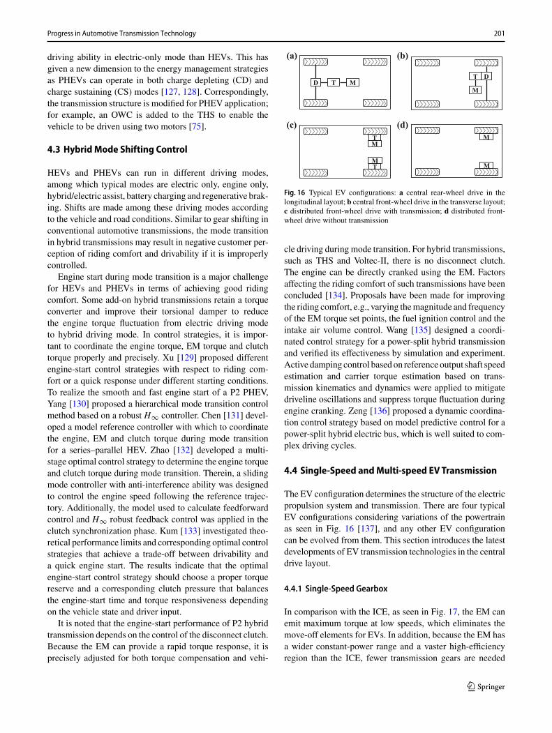
Fig. 16 Typical EV configurations: a central rear-wheel drive in thelongitudinal layout; b central front-wheel drive in the transverse layout;c distributed front-wheel drive with transmission; d distributed front-wheel drive without transmission
cle driving during mode transition. For hybrid transmissions,such as THS and Voltec-II, there is no disconnect clutch.The engine can be directly cranked using the EM. Factorsaffecting the riding comfort of such transmissions have beenconcluded [134]. Proposals have been made for improvingthe riding comfort, e.g., varying themagnitude and frequencyof the EM torque set points, the fuel ignition control and theintake air volume control. Wang [135] designed a coordi-nated control strategy for a power-split hybrid transmissionand verified its effectiveness by simulation and experiment.Active damping control based on reference output shaft speedestimation and carrier torque estimation based on trans-mission kinematics and dynamics were applied to mitigatedriveline oscillations and suppress torque fluctuation duringengine cranking. Zeng [136] proposed a dynamic coordina-tion control strategy based on model predictive control for apower-split hybrid electric bus, which is well suited to com-plex driving cycles.
4.4 Single-Speed andMulti-speed EV Transmission
The EV configuration determines the structure of the electricpropulsion system and transmission. There are four typicalEV configurations considering variations of the powertrainas seen in Fig. 16 [137], and any other EV configurationcan be evolved from them. This section introduces the latestdevelopments of EV transmission technologies in the centraldrive layout.
4.4.1 Single-Speed Gearbox
In comparison with the ICE, as seen in Fig. 17, the EM canemit maximum torque at low speeds, which eliminates themove-off elements for EVs. In addition, because the EM hasa wider constant-power range and a vaster high-efficiencyregion than the ICE, fewer transmission gears are needed
123

202 X. Xu et al.
Fig. 17 Comparison of thecharacteristics of the EM andICE Torque
Power
SpeedBase Speed
Torque
Power
SpeedIdle Speed
(a) (b)
Table 1 Mass-produced EVs
EV Company Curb weight(kg)
Maximumpower (kW)
Maximumtorque (Nm)
Maximumvehicle speed(kph)
Maximummotor speed(rpm)
Gear ratio
Model S Tesla 2239 581(combined)
1250(combined)
249 16,000 (rearmotor)
9.73 (reargearbox)
Bolt Chevrolet 1625 150 360 140 8810 7.05
Leaf Nissan 1557 110 320 140 10,390 7.937
i3 BMW 1298 125 250 150 11,400 9.7
Zoe Renault 1468 68 220 135 12,000 9.32
EC180 BJEV 1050 30 140 100 8000 6.71
to meet traction and energy-saving demands. Furthermore,the torque ripple of various EMs is much smaller than thatof the ICE and the torsion damper can correspondingly beabolished for EVs. To reduce the volume and costs of thepowertrain and to shorten the development cycle, consider-ing the above advantages of the EM, most mass-producedEVs use a single-speed gearbox to adapt the traction avail-able to the power required as seen in Table 1. Obviously,greater torque with a large gear ratio is required to satisfydriving performance demands, and higher-speed EMs haveaccordingly been developed to meet the maximum vehiclespeed.
Figure 18 shows a typical structure of the EV power-train with a single-speed gearbox [138], which uses twoPGPs to realize a total gear ratio of 7.05. Such an inte-grated and coaxial configuration not only minimizes thevolume of the powertrain but also makes the most of the oilpump to lubricate and cool both the EM and gearbox. Mostother mass-produced single-speed gearboxes have generallyadopted PGPs considering costs and efficiency; however,PGSsprovide a larger gear ratio to lower themaximum torqueof the EM. Figure 19 shows that combining a PGS with aPGP, ZF’s EV drive 1 realizes a total gear ratio of 16, whichreduces the maximum EM torque to 125 Nm but raises themaximum EM speed to 21,000 rpm [139].
4.4.2 Multi-speed Transmission
To improve the dynamic performance and economy of anEV or to reduce the maximum EM torque and the max-
Fig. 18 Structure of the Chevrolet Bolt EV powertrain. (Reproducedwith permission from [138])
Fig. 19 Structure of ZF’s EV drive 1. (Reproduced with permissionfrom [139])
123
Progress in Automotive Transmission Technology 203
Complexity&Costs
Efficiency
Volume&MassShift Quality
Torque Capacity
AMT DCT AT ECVT New Configurations
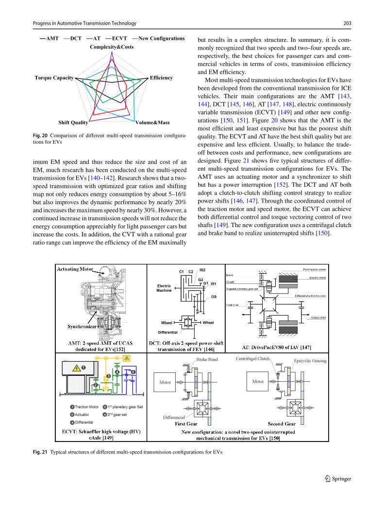
Fig. 20 Comparison of different multi-speed transmission configura-tions for EVs
imum EM speed and thus reduce the size and cost of anEM, much research has been conducted on the multi-speedtransmission for EVs [140–142]. Research shows that a two-speed transmission with optimized gear ratios and shiftingmap not only reduces energy consumption by about 5–16%but also improves the dynamic performance by nearly 20%and increases themaximumspeed by nearly 30%.However, acontinued increase in transmission speeds will not reduce theenergy consumption appreciably for light passenger cars butincrease the costs. In addition, the CVT with a rational gearratio range can improve the efficiency of the EM maximally
but results in a complex structure. In summary, it is com-monly recognized that two speeds and two–four speeds are,respectively, the best choices for passenger cars and com-mercial vehicles in terms of costs, transmission efficiencyand EM efficiency.
Most multi-speed transmission technologies for EVs havebeen developed from the conventional transmission for ICEvehicles. Their main configurations are the AMT [143,144], DCT [145, 146], AT [147, 148], electric continuouslyvariable transmission (ECVT) [149] and other new config-urations [150, 151]. Figure 20 shows that the AMT is themost efficient and least expensive but has the poorest shiftquality. The ECVT and AT have the best shift quality but areexpensive and less efficient. Usually, to balance the trade-off between costs and performance, new configurations aredesigned. Figure 21 shows five typical structures of differ-ent multi-speed transmission configurations for EVs. TheAMT uses an actuating motor and a synchronizer to shiftbut has a power interruption [152]. The DCT and AT bothadopt a clutch-to-clutch shifting control strategy to realizepower shifts [146, 147]. Through the coordinated control ofthe traction motor and speed motor, the ECVT can achieveboth differential control and torque vectoring control of twoshafts [149]. The new configuration uses a centrifugal clutchand brake band to realize uninterrupted shifts [150].
Fig. 21 Typical structures of different multi-speed transmission configurations for EVs
123

204 X. Xu et al.
Fig. 22 Two typical types of distributed-drive EVs: a in-wheel motors;b motors with gearboxes
4.5 Distributed Electric Drive
In a distributed electric drive, the wheels are directly drivenby electric motors. Figure 22 shows that, generally, there aretwo typical types of distributed-drive EVs [153]. In the firsttype, themotors aremounted in thewheel hubs. In the secondtype, a gearbox is used between the electric motor andwheel.In some practical cases, there are only two electric motorsinstead of four, with the motors directly driving the frontwheels or rear wheels.
The powertrain of a traditional vehicle consists of anengine, clutch, transmission, shaft or two shafts, and dif-ferential. Compared with the traditional powertrain, thedistributed-drive electric powertrain has several advantages[154, 155]:
1. Simpler vehicle architecture, vehicle design and packag-ing;
2. Higher drive efficiency and less vehicle mass;3. Amore precise and faster response to the torque demand;4. Higher regenerated brake energy and less energy con-
sumption.
Because there are no gearboxes, the in-wheel-motor-drive EVs have the potential to save energy compared with
the counterpart of motor-gearbox-drive EVs. However, thedesign of in-wheel motors is more challenging in terms ofthe size control and thermal management. After decadesof development, there are several well-recognized in-wheelmotors and motor-hub wheels on the current market. Fig-ure 23 depicts three examples, namely e-Traction, Proteanand Elaphe. We see that all of them are compact.
Owing to the benefits of well-developed in-wheel motorsand motor-hub wheels, the integration and dynamics con-trol of distributed-drive EVs have attracted attention fromresearchers over the past two decades. Table 2 shows thatdifferent prototypes of distributed-drive EVs have beendeveloped in Japan, the USA, China, Europe and Canada.It has been reported that distributed-drive EVs can be rep-resented by an over-actuator system [156, 157]. The motioncontrol of longitudinal and lateral directions is then relativelydifficult but flexible. Considerable methodologies have beenapplied tomotion control for the purpose of improving safety,agility, handling and fuel economy [158–165]. Another hotresearch topic of distributed-drive EVs is how to reduce theeffect of the unsprungmass on the vehicle dynamics and con-trol [166, 167]. Research and improvements of the techniqueare ongoing for the industrialization of distributed-drive EVs.Distributed-drive EVs will be widely used on the road in thenear future.
5 Summary and Outlook
Over the past two decades, automotive transmissions haveevolved with greater speed numbers, an expanded ratiospread and improved efficiency and shift quality. DCTs werelaunched onto the market in 2003, offering both high effi-ciency and a fast shift and thus promoting the developmentof ATs and CVTs. Novel ATs with four or five DOFs werereleased continuously with higher efficiency and better shiftquality. The torque capacity and efficiency of CVTs havealso been improved. It is clear that ATs, DCTs and CVTswill coexist in the passenger car market in the future. Inthe commercial vehicle market, AMTs and ATs will bedominant. The increase in the speed number of conven-
Fig. 23 Three commercialin-wheel motors and motor-hubwheels on the market: ae-Traction; b Protean; c Elaphe
123

Progress in Automotive Transmission Technology 205
Table 2 Worldwide research groups with prototypes of distributed-drive EVs
Group and university Prototype and platformYoichi Hori ‘s group from University of Tokyo, Japan [168, 169]
Junmin Wang’s group from The Ohio State University, USA [170, 171]
European Union FP7 project E-VECTOORC [172, 173]
Hiroshi Fujimoto’s group from University of Tokyo,Japan [174, 175]
Jibin Hu’s group from Beijing Institute of Technology, China [176, 177]
Zhuoping Yu’s group from Tongji University, China [178,179]
Amir Khajepour’s group from University of Waterloo, Canada [180, 181]
tional automotive transmissions has almost come to an end.In the future, the focus will remain on the optimizationof the transmission’s mechanical and hydraulic systems interms of efficiency, NVH in terms of driving comfort andshifting strategy and control technology in terms of shiftquality.
It is evident that the development trend of automotivetransmissions is electrification. For hybrid transmissions,add-on solutions and DHT solutions coexist on the market.However, it is believed that DHT has a bright future with theincreasing volume of hybrid vehicles. The energy manage-ment strategy is the key for realizing fuel savings of HEVsand PHEVs. With the development of electronics and com-putation capability, the energy management strategy will beoptimized in real time according to the route informationaccessed via the Global Positioning System. Mode shiftingcontrol will be improved to make the shift event impercepti-ble to the driver.
The single-speed gearbox currently dominates the EVmarket. In the future, two- or three-speed transmission willoccupy a certain EV market share, lowering the torqueand speed requirements of the EM. Meanwhile, EV trans-mission will be integrated with the EM and power elec-tronics step by step from a modular design to a semi-integrated design, an integrated design and finally a fullyintegrated design. The distributed electric drive will firstenter the market of commercial vehicles (e.g., buses and mil-itary vehicles) before penetrating the market of passengercars.
Acknowledgements The authors acknowledge the support of BeijingKey Laboratory for High-efficient Power Transmission and SystemControl of New Energy Resource Vehicle. This work is financially sup-ported by the National Key R&D Program of China “Development andVehicle Integration of Cost-effective Commercial Vehicle Hybrid Sys-tem” (Grant No. 2018YFB0105900). The authors are grateful for thecontributions ofDr. YunjiangCheng and postgraduate students HanqiaoSun, Xiaoxiao Wu, Junbin Lai, Songlin Li, Lei Shi and Huize Ding.
Open Access This article is distributed under the terms of the CreativeCommons Attribution 4.0 International License (http://creativecommons.org/licenses/by/4.0/), which permits unrestricted use, distribution,and reproduction in any medium, provided you give appropriate creditto the original author(s) and the source, provide a link to the CreativeCommons license, and indicate if changes were made.
References
1. Yan, Q.D., Li, S.L., Yao, S.W.: Analysis method of planetaryspeed-shifting mechanism based on graph theory. J. Jilin Univ.Eng. Technol. Ed. 40(4), 1029–1033 (2010)
2. Tan, G.H.: A study on the development of mechanical drive ofvehicle transmission. J. Zhuzhou Inst. Technol. 20(4), 49–52(2006)
3. Liu, X.J.: The multi-member planetary gearing layout analysisand design. J. Beijing Inst. Technol. Engl. Ed. 1, 74–91 (1984)
123
206 X. Xu et al.
4. Dong, P., Liu, Y.F., Tenberge, P., et al.: Design and analysis of anovel multi-speed automatic transmission with four degrees-of-freedom. Mech. Mach. Theory 108, 83–96 (2017)
5. Wan, Y.Q., Wang, W.Q.: The development and application of themulti-freedom degrees planetary gear box scheme synthetical.Mach. Des. 15(10), 7–9 (1998)
6. Xie, T.L.: Topology synthesis of planetary gear trainwithmultipledegrees of freedom for vehicle. Beijing Institute of Technology.Dissertation (2015)
7. Liu, T.L.: The synthetical method of multi-speed planetary gear-box with three degrees of freedom by means of computer. Veh.Power Technol. 1, 51–58 (1984)
8. Radzevich, S.P.: Theory of gearing: kinetics, geometry, and syn-thesis. CRC Press, Boca Raton (2013)
9. Wan, Y.Q.: The theory of computer aided design of multi-DOFplanetary gearbox scheme. Mach. Des. Res. 3, 13–19 (1984)
10. Tian, N.S., Zhou, S.R.: A research on the optimizing method ofthe scheme of multivariant planetary transmission. J. Railw. Sci.Eng. 14(2), 19–26 (1996)
11. Liu,B.D., Li, J., Li, L.Z.: Combined solutionmethod for optimiza-tion of multi-degree-of-freedom planetary gearbox. Veh. PowerTechnol. 1, 12–24 (1987)
12. Kahraman, A., Ligata, H., Kienzle, K., et al.: A kinematics andpower flow analysis methodology for automatic transmissionplanetary gear trains. J. Mech. Des. 126(6), 1071–1081 (2004)
13. Inalpolat, M., Kahraman, A.: A dynamic model to predict mod-ulation sidebands of a planetary gear set having manufacturingerrors. J. Sound Vib. 329(4), 371–393 (2010)
14. Xu, A.F., Jia, J.M., Liu, N.: Study on the gearing scheme of plan-etary gear train based on improved lever analogy. J. Mil. Transp.Univ. 16(7), 91–95 (2014)
15. Wang, Z., Zhang, J., Zhang, Y.: A novel graphic characteristicbased method for topology analysis in substations and powerplants. Trans. China Electrotech. Soc. 27(2), 255–260 (2012)
16. Tsai, L.W.: An application of the linkage characteristic polyno-mial to the topological synthesis of epicyclic gear trains. J. Mech.Transm. Autom. Des. 109(3), 329–336 (1987)
17. Dobrjanskyj, L., Freudenstein, F.: Some applications of graph the-ory to the structural analysis of mechanisms. J. Eng. Ind. 89(1),153–158 (1967)
18. Buchsbaum, F., Freudenstein, F.: Synthesis of kinematic structureof geared kinematic chains and other mechanisms. J. Mech. 5(3),357–392 (1970)
19. Kurth, F.: Efficiency determination and synthesis of complex—compound planetary gear transmissions. Technische UniversitätMünchen. Dissertation (2012)
20. Troha, S., Lovrin, N., Milovancevic, M.: Selection of the two-carrier shifting planetary gear train controlled by clutches andbrakes. Trans. Famena 36(3), 1–12 (2012)
21. Arnaudov, K., Karaivanov, D.: Higher compound planetary geartrains. Proc. VDI Berichte 1904(1), 327–344 (2005)
22. Li, S.l.: Computer aided design of planetary transmission schemebased on graph theory. Beijing Institute of Technology. Disserta-tion (2009)
23. Gumpoltsberger, G.: Systematische synthese und bewertung vonmehrgängigen planetengetrieben. Chemnitz University of Tech-nology. Dissertation (2007)
24. Ma, M.Y., Liu, Y.F., Xu, X.Y., et al.: Automatic detection of geo-metric compatibility for planetary gear train. Autom. Eng. 36(5),603–607 (2014)
25. Ma,M.Y., Liu, Y.F., Xu, X.Y., et al.: Structure synthesis of 4-DOFplanetary transmission. J. Mech. Transm. 38(9), 34–38 (2014)
26. Yuan, S.H., Liu, H., Peng, Z.X., et al.: Analysis of the compoundsplit transmission based on the four-port power split device. J.Beijing Inst. Technol. Engl. Ed. 21(1), 50–57 (2012)
27. Liao, Y.G., Chen,M.Y.: Analysis of multi-speed transmission andelectrically continuous variable transmission using lever analogymethod for speed ratio determination. Adv.Mech. Eng. 9(8), 1–12(2017)
28. Liu, J., Peng, H.: Modeling and control of a power-split hybridvehicle. IEEE Trans. Control Syst. Technol. 16(6), 1242–1251(2008)
29. Zhuang, W.C., Zhang, X.W., Zhao, D., et al.: Optimal designof three-planetary-gear power-split hybrid powertrains. Int. J.Autom. Technol. 17(2), 299–309 (2016)
30. Zhuang, W.C., Zhang, X.W., Zhao, D., et al.: Rapid configurationdesign of multiple-planetary-gear power-split hybrid powertrainvia mode combination. IEEE/ASME Trans. Mechatron. 21(6),2924–2934 (2016)
31. Zhang, X.W., Peng, H., Sun, J., et al.: Automated modeling andmode screening for exhaustive search of double-planetary-gearpower split hybrid powertrains. In: Proceedings of the ASME 7thAnnual Dynamic Systems and Control Conference, San Antonio,USA (2014)
32. Tsai, L.W., Schultz, G.: A motor-integrated parallel hybrid trans-mission. J. Mech. Des. 126(5), 889–894 (2004)
33. Dagci, O.H., Peng, H., Grizzle, J.W.: Hybrid electric powertraindesign methodology with planetary gear sets for performance andfuel economy. IEEE Access 6, 9585–9602 (2018)
34. Qin, Z., Luo, Y., Li, K., et al.: A new powertrain design approachfor power-split hybrid tracked vehicles. In: Proceedings of theASME 2017 Dynamic Systems and Control Conference, TysonsCorner, USA (2017)
35. Qin, Z., Luo, Y., Li, K., et al.: Optimal design of a novelhybrid electric powertrain for tracked vehicles. Energies 10(12),2141–2165 (2017)
36. Zhuang, W., Zhang, X., Peng, H., et al.: Simultaneous optimiza-tion of topology and component sizes for double planetary gearhybrid powertrains. Energies 9(6), 411–427 (2016)
37. Dagci, O.H., Peng, H.: A method for the exploration of hybridelectric powertrain architectureswith two planetary gearsets. SAEInt. J. Altern. Powertrains 5(1), 94–108 (2016)
38. Ngo, H.T., Yan, H.S.: Configuration synthesis of parallel hybridtransmissions. Mech. Mach. Theory 97, 51–71 (2016)
39. Ngo, H.T., Yan, H.S.: Novel configurations for hybrid transmis-sions using a simple planetary gear train. J. Mech. Robot. 8(2),1–10 (2016)
40. Hellenbroich, G., Ruschhaupt, J.: Innovative xDCT family ofFEV-extremely compact 7 and 10 speed DCTs. In: Proceedingsof Symposium on International Automotive Technology, India(2013)
41. Leesch, M.: Beitrag zur systematischen synthese und bewertungvon doppelkupplungsgetrieben. Chemnitz University of Technol-ogy. Dissertation (2012)
42. Yue, J.H., Li, H.: Parameter optimization of 7 shafts transmis-sion system based on MATLAB. J. Mech. Transm. 39(5), 80–84(2015)
43. Ma, M.Y., Liu, Y.F., Xu, X.Y., et al.: Selection of shifting elementdesign based on genetic algorithm. J. Beijing Univ. Aeronaut.Astronaut. 40(10), 1327–1377 (2014)
44. Rossetti, A., Macor, A.: Multi-objective optimization of hydro-mechanical power split transmissions. Mech. Mach. Theory 62,112–128 (2013)
45. Xu, X.Y., Chen, Z.F., Liu, Y.J., et al.: Enumerative optimizationprocedure for the gear train optimization problem of a two-speed dedicated electric transmission. Energies 10(9), 1362–1385(2017)
46. Chen, Z.F.: Critical technologies of the mechatronic system of atwo-speed automatic transmission dedicated for electric vehicles.Beihang University. Dissertation (2018)
123
Progress in Automotive Transmission Technology 207
47. Zhang, X., Peng, H., Sun, J.: A near-optimal power manage-ment strategy for rapid component sizing of multimode powersplit hybrid vehicles. IEEE Trans. Control Syst. Technol. 23(2),609–618 (2015)
48. Koguchi, T.: Evolution of a CVT with an auxiliary gearbox. In:Proceedings of the 9th International CTI Symposium. Shanghai,China (2015)
49. Scherer, H.: ZF 6-speed automatic transmission for passengercars. SAE Technical Paper 2003-01-0596 (2003)
50. Dick, A., Greiner, J., Locher, A., et al.: Optimization potential fora state of the art 8-Speed AT. SAE Int. J. Passeng. Cars Mech.Syst. 6(2), 899–907 (2013)
51. Uozumi, S., Taniguchi, T., Tsukamoto, K., et al.: AISIN AW newsix-speed automatic transmission for RWD vehicles. SAE Tech-nical Paper 2004-01-0652 (2004)
52. Kondo, M., Hasegawa, Y., Takanami, Y., et al.: Toyota AA80E8-speed automatic transmissionwith novel powertrain control sys-tem. SAE Technical Paper 2007-01-1311 (2007)
53. Suzuki, T., Sugiura, H., Niinomi, A., et al.: New RWD 10speed automatic transmission for passenger vehicles. SAE Int.J. Engines 10(2), 695–700 (2017)
54. Greiner, J., Doerr, C., Nauerz, H., et al.: The new “7G-TRONIC”of Mercedes-Benz: innovative transmission technology for betterdriving performance, comfort and fuel economy. SAE TechnicalPaper 2004-01-0649 (2004)
55. Doerr, C., Homm, M., Indlekofer, G.: The new automatic trans-mission 9G-Tronic from Mercedes-Benz. In: Proceedings of the12th International CTI Symposium-Automotive Transmissionsand HEV and EV Drives, Berlin, Germany, pp. 153–160 (2013)
56. Hart, J.M.: General motors rear wheel drive eight speed automatictransmission. SAE Int. J. Passeng. CarsMech. Syst. 7(1), 289–294(2014)
57. Brehmer,M.,Diosi,G.,Haupt, J.: 10-gear automatic transmission.Patent US 13/852589 (2013)
58. Kluemper, S.: Allison’s new 9-speed medium duty fully auto-matic transmission. In: Proceedings of the 12th International CTISymposium, Michigan, USA (2018)
59. Gaertner, L., Ebenhoch, M.: The ZF automatic transmission9HP48 transmission system, design and mechanical parts. SAEInt. J. Passeng. Cars Mech. Syst. 6(2), 908–917 (2013)
60. Katou, N., Taniguchi, T., Tsukamoto, K., et al.: AISIN AW newsix-speed automatic transmission for FWD vehicles. SAE Tech-nical Paper 2004-01-0651 (2004)
61. Aoki, T., Kato, H., Kato, N., et al.: The world’s first transverse8-speed automatic transmission. SAE Technical Paper 2013-01-1274 (2013)
62. Fischer, H.C., Diaz-Theilmann, A., Lecomte, O., et al.: Third gen-eration of Global FWD 6-speed Automatic Transmission (GF6).In: Proceedings of International VDI Congress, Friedrichshafen,Germany, pp. 299–316 (2014)
63. Bockenstette, C.M., Marin, C.E., Otanez, P.G., et al.: Nine speedtransmission with latching mechanism. Patent US 20140378266(2014)
64. Renneker, C.: Ford’s “Hat Trick”: 3 new 8-speed automatictransmissions. In: Proceedings of the 12th International CTI Sym-posium, Michigan, USA (2018)
65. Suigino, S.,Muramatsu, I.: Honda’s 10-speed automatic transmis-sion. In: Proceedings of the 12th International CTI Symposium,Michigan, USA (2018)
66. Fu, Y.X., Yang, Y., Xu, X.Y., et al.: A new archetype of automatictransmission. SAE Technical Paper 2011-01-1429 (2011)
67. Schreiber, W., Rudolph, F., Becker, V.: The new dual clutch gear-box from Volkswagen. ATZ Worldw. 105(11), 2–6 (2003)
68. Hadler, J., Metzner, F., Schäfer, M., et al.: The seven-speeddual clutch transmission from Volkswagen. ATZWorldw. 110(6),26–33 (2008)
69. Hadler, J., Schäfer, M., Gröhlich, H., et al.: DQ500—the newVolkswagen seven-speed dual-clutch gearbox for high torques.In: Proceedings of the 18th Aachen Colloquium Automobile andEngine Technology, Aachen, Germany (2009)
70. Machida, S., Yagi, N., Miyata, K., et al.: Development of 8-speedDCT with torque converter for midsize vehicles. Honda R&DTech. Rev. 26, 119–125 (2014)
71. Donges, A., Jauch, F., Sibla, C.: CO2 potentials for further devel-opment of the 8HP transmission kit. In: Proceedings of the 16thInternational CTI Symposium, Berlin, Germany (2017)
72. Schulz, J.: Separating springs for active separation of the frictionplates in wet clutch systems. In: Proceedings of the 10th Interna-tional CTI Symposium and Exhibition, Berlin, Germany (2011)
73. Naunheimer, H., Bertsche, B., Ryborz, J., et al.: Automotivetransmissions: fundamentals, selection, design and application.Springer, Berlin (2011)
74. Dörr, C., Kalczynski, H., Rink, A., et al.: Nine-speed automatictransmission 9G-Tronic byMercedes-Benz.ATZWorldw. 116(1),20–25 (2014)
75. Ichikawa, S., Takeuchi, H., Fukuda, S., et al.: Development ofnew plug-in hybrid system for compact-class vehicle. SAE Int. J.Altern. Powertrains 6(1), 95–102 (2017)
76. Iwasawa, T., Momoi, M., Hayakawa, K., et al.: Development ofnew variator system for the Jatco CVT7 W/R. In: Proceedings of5th International CTI Symposium, Shanghai, China (2016)
77. Dong, P., Liu, Y.F., Xu, X.Y.: A method of applying two-pumpsystem in automatic transmissions for energy conservation. Adv.Mech. Eng. 7(7), 1–11 (2015)
78. Liu,Y.F.,Dong, P., Liu,Y., et al.:Design and application of electricoil pump in automatic transmission for efficiency improvementand start–stop function. J. Central South Univ. 23(3), 570–580(2016)
79. Liu, Y.,Wang, S.H., Dong, P., et al.: Dynamic analysis and controlof an automatic transmission for start–stop function and efficiencyimprovement. Math. Probl. Eng. 2015, 1–13 (2015)
80. Li, R.F., Wang, J.J.: Geared system dynamic-vibration, shock andnoise. China Science Press, Beijing (1997)
81. Houser, D.R., Ueda, Y., Harianto, J.: Determining the source ofgear whine noise. Gear Solut. 2, 17–22 (2004)
82. Smith, J.D.: Gear Noise and Vibration. Marcel Dekker, NewYork(2003)
83. Lei, Y.L., Hou, L.G., Fu, Y., et al.: Transmission gear whine con-trol bymulti-objective optimization andmodification design. SAETechnical Paper 2018-01-0993 (2018)
84. Bellomo, P., De Vito, N., Lang, C.H., et al.: In depth study ofvehicle powertrains to identify causes of loose components rattlein transmissions. SAE Technical Paper 2002-01-0702 (2002)
85. Jadhav, S.M.: Powertrain NVH analysis including clutch and geardynamics. SAE Technical Paper 2014-01-1680 (2014)
86. Galvagno, E., Guercioni, G.R., Vigliani, A.: Sensitivity analysisof the design parameters of a dual-clutch transmission focused onNVH performance. SAE Technical Paper 2016-01-1127 (2016)
87. Crowther, A.R., Zhang, N., Singh, R.: Development of a clunksimulation model for a rear wheel drive vehicle with automatictransmission. SAE Technical Paper 2005-01-2292 (2005)
88. Wang, J., Lei, Y., Ge, A., et al.: Noise quality analysis and met-rics development under transient shifting condition. SAE Int. J.Passeng. Cars Mech. Syst. 1(1), 250–257 (2008)
89. Chaturvedi, G.K., Thomas, D.W.: Bearing fault detection usingadaptive noise cancelling. J. Mech. Des. 104(2), 280–289 (1982)
90. Yue, G., Niu, W., Zhao, J., et al.: Gear whine resolution by toothmodification and multi-body dynamics analysis. SAE TechnicalPaper 2016-01-1061 (2016)
91. Bile, Y., Gondhalekar, A., Kumbhar, M.: Studies on neutral gearrattle in early stage design. SAE Technical Paper 2013-26-0109(2013)
123

208 X. Xu et al.
92. Campbell, B., Stokes, W., Steyer, G., et al.: Gear noise reduc-tion of an automatic transmission through finite element dynamicsimulation. SAE Technical Paper 971966 (1997)
93. Montanari, M., Ronchi, F., Rossi, C., et al.: Control and per-formance evaluation of a clutch servo system with hydraulicactuation. Control Eng. Pract. 12(11), 1369–1379 (2004)
94. Watson, M., Byington, C., Edward, D., et al.: Dynamic modelingand wear-based remaining useful life prediction of high powerclutch systems. Tribol. Trans. 48(2), 208–217 (2005)
95. Walker, P.D., Zhu,B., Zhang,N.:Nonlinearmodeling and analysisof direct acting solenoid valves for clutch control. J. Dyn. Syst.Meas. Contr. 136(5), 1–9 (2014)
96. Liu, Z., Gao, J., Zheng, Q.: Robust clutch slip controller designfor automatic transmission. Proc. Inst. Mech. Eng. D J. Autom.Eng. 225(8), 989–1005 (2011)
97. Van de Ven, J.D., Cusack, J.: Synthesis and baseline testingof a digital pulse-width-modulated clutch. Mech. Mach. Theory78(78), 81–91 (2014)
98. Dutta, A., Depraetere, B., Ionescu, C., et al.: Comparison of two-level NMPC and ILC strategies for wet-clutch control. ControlEng. Pract. 22, 114–124 (2014)
99. Dutta, A., Zhong, Y., Depraetere, B., et al.: Model-based andmodel-free learning strategies for wet clutch control. Mechatron-ics 24(8), 1008–1020 (2014)
100. Meng, F., Chen, H.Y., Zhang, T., et al.: Clutch fill control ofan automatic transmission for heavy-duty vehicle applications.Mech. Syst. Signal Process. 64–65, 16–28 (2015)
101. Pinte, G., Depraetere, B., Symens, W., et al.: Iterative learningcontrol for the filling of wet clutches. Mech. Syst. Signal Process.24(7), 1924–1937 (2010)
102. Gao, B.Z., Chen, H., Hu, Y.F., et al.: Nonlinear feedforward–feed-back control of clutch-to-clutch shift technique. Veh. Syst. Dyn.49(12), 1895–1911 (2011)
103. Gao, B.Z., Chen,H., Li, J., et al.: Observer-based feedback controlduring torque phase of clutch-to-clutch shift process. Int. J. Veh.Des. 58(1), 93–108 (2012)
104. Chen, L., Xi, G., Yin, C.L.: Model referenced adaptive control tocompensate slip-stick transition during clutch engagement. Int. J.Autom. Technol. 12(6), 913–920 (2011)
105. Dutta, A., Ionescu, C.M., De Keyser, R., et al.: Robust andtwo-level (nonlinear) predictive control of switched dynamicalsystems with unknown references for optimal wet-clutch engage-ment. Proc. Inst. Mech. Eng. I J. Syst. Control Eng. 228(4),233–244 (2013)
106. Song, X., Sun, Z.: Pressure-based clutch control for automo-tive transmissions using a sliding-mode controller. IEEE/ASMETrans. Mechatron. 17(3), 534–546 (2012)
107. Watechagit, S.: Modeling and estimation for stepped automatictransmission with clutch-to-clutch shift technology. University ofOhio State. Dissertation (2004)
108. Liu, Y.G., Qin, D.T., Jiang, H., et al.: Shift control strategy andexperimental validation for dry dual clutch transmissions. Mech.Mach. Theory 75, 41–53 (2014)
109. Van Berkel, K., Hofman, T., Serrarens, A., et al.: Fast and smoothclutch engagement control for dual-clutch transmissions. ControlEng. Pract. 22, 57–68 (2014)
110. Mishra, K.D., Srinivasan, K.: Robust nonlinear control of iner-tia phase in clutch-to-clutch shifts. IFAC-PapersOnLine 48(15),277–284 (2015)
111. Hu, Y.F., Tian, L., Gao, B.Z., et al.: Nonlinear gearshifts control ofdual-clutch transmissions during inertia phase. ISA Trans. 53(4),1320–1331 (2014)
112. Liu, Q.F., Chen, H., Gao, B.Z., et al.: Shift control of dual clutchtransmission using triple-step nonlinear method. IFAC Proc. Vol.47(3), 5884–5889 (2014)
113. Zhao, Z.G., He, L., Zheng, Z.X., et al.: Self-adaptive optimal con-trol of dry dual clutch transmission (DCT) during starting process.Mech. Syst. Signal Process. 68–69, 504–522 (2016)
114. Kim, D., Hahn, J., Shin, B., et al.: Adaptive compensation con-trol of vehicle automatic transmissions for smooth shift transientsbased on intelligent supervisor. KSME Int. J. 15(11), 1472–1481(2001)
115. Shi, G., Dong, P., Sun, H.Q., et al.: Adaptive control of the shiftingprocess in automatic transmissions. Int. J. Autom. Technol. 18(1),179–194 (2017)
116. Dan, W., Shimada, T.: Improvement of CVT acceleration feelingutilizing stepwise shift control. In: Proceedings of the 5th Inter-national CTI Symposium, Shanghai, China (2016)
117. Heller, S.: The new BMW hybrid powertrain with eight-speedhybrid transmission. In: Proceedings of the 4th International CTISymposium, Shanghai, China (2015)
118. Xu, X.Y.: Development of transmission technology for energy-saving vehicles and new energy resource vehicle. J. Autom. Saf.Energy 8(4), 323–332 (2017)
119. Meisel, J.: An analytic foundation for the Toyota Prius THS-IIpowertrain with a comparison to a strong parallel hybrid-electricpowertrain. SAE Technical Paper 2006-01-0666 (2006)
120. Suzuki, Y., Nishimine, A., Baba, S., et al.: Development of newplug-in hybrid transaxle for compact-class vehicles. SAE Techni-cal Paper 2017-01-1151 (2017)
121. Cesiel, D., Zhu, C.: Next generation “Voltec” charging system.SAE Technical Paper 2016-01-1229 (2016)
122. Shen, D.F., Wang, C., Yu, H.S., et al.: A study on energy manage-ment strategy for compound power-split hybrid electric vehicle.Autom. Eng. 39(1), 15–22 (2017)
123. Inoue, M., Takamatsu, H., Ogami, M., et al.: New-structure motorfor full hybrid electric vehicle. SAETechical Paper 2016-01-1225(2016)
124. Leng, H.X., Ge, H.L., Sun, J., et al.: SAIC Roewe 550 plug-inhybrid electric system. Sci. Technol. Rev. 34(6), 90–97 (2016)
125. Huang, Y., Wang, H., Khajepour, A.: Model predictive con-trol power management strategies for HEVs: a review. J. PowerSources 341, 91–106 (2017)
126. Zhuang, W., Zhang, X., Li, D.: Mode shift map design and inte-grated energymanagement control of amulti-mode hybrid electricvehicle. Appl. Energy 204, 476–488 (2017)
127. Gao, Y., Ehsani, M.: Design and control methodology of plug-in hybrid electric vehicles. IEEE Trans. Industr. Electron. 57(2),633–640 (2010)
128. Somayajula, D., Meintz, A., Ferdowsi, M.: Designing efficienthybrid electric vehicles. IEEE Veh. Technol. Mag. 4(2), 65–72(2009)
129. Xu, X.Y., Wu, X.X., Jordan, M., et al.: Coordinated engine-startcontrol of single-motor P2 hybrid electric vehicles with respectto different driving situations. Energies 11(1), 207–229 (2018)
130. Yang, C., Jiao, X.H., Li, L., et al.: A robust H∞ control-basedhierarchical mode transition control system for plug-in hybridelectric vehicle. Mech. Syst. Signal Process. 99, 326–344 (2018)
131. Chen, L., Xi, G., Sun, J.: Torque coordination control duringmodetransition for a series–parallel hybrid electric vehicle. IEEETrans.Veh. Technol. 61(7), 2936–2949 (2012)
132. Zhao, Z.G., Lei, D., Chen, J., et al.: Optimal control of modetransition for four-wheel-drive hybrid electric vehicle with drydual-clutch transmission. Mech. Syst. Signal Process. 105, 68–89(2018)
133. Kum, D.: Control of engine-starts for optimal drivability of par-allel hybrid electric vehicles. J. Dyn. Syst. Meas. Contr. 135(2),450–472 (2013)
134. Yoshioka,T., Sugita,H.:Noise andvibration reduction technologyin hybrid vehicle development. SAE Technical Paper 2001-01-1415 (2001)
123

Progress in Automotive Transmission Technology 209
135. Wang, C., Zhao, Z., Zhang, T., et al.: Mode transition coordinatedcontrol for a compound power-split hybrid car.Mech. Syst. SignalProcess. 87, 192–205 (2017)
136. Zeng, X., Yang, N., Wang, J., et al.: Predictive-model-baseddynamic coordination control strategy for power-split hybridelectric bus. Mech. Syst. Signal Process. 60–61, 785–798(2015)
137. Ehsani, M., Gao, Y., Emadi, A.: Modern electric, hybrid electric,and fuel cell vehicles: fundamentals, theory, and design. CRCPress, Boca Raton (2005)
138. Liu, J., Anwar, M., Chiang, P., et al.: Design of the ChevroletBolt EV propulsion system. SAE Int. J. Altern. Powertrains 5(1),79–86 (2016)
139. Scharr, S., Vahlensieck, B., Ketteler, K.H., et al.: First resultsfrom driving and testing ZF’s electric vehicle drive EVD1. In:Proceedings of 2013 T/M Symposium, Suzhou, China (2013)
140. Ruan, J.G., Walker, P.D., Zhang, N., et al.: An investigation ofhybrid energy storage system in multi-speed electric vehicle.Energy 140(1), 291–306 (2017)
141. Sorniotti, A., Subramanyan, S., Turner, A., et al.: Selection of theoptimal gearbox layout for an electric vehicle. SAE Int. J. Engines4(1), 1267–1280 (2011)
142. Wu, X.X., Dong, P., Xu, X.Y., et al.: Energy conservationof electric vehicles by applying multi-speed transmissions. In:Proceedings of International Conference on Automotive Engi-neering, Mechanical and Electrical Engineering, Hong Kong,China, pp. 15–22 (2017)
143. Gao, B., Liang, Q., Xiang, Y., et al.: Gear ratio optimization andshift control of 2-speed I-AMT in electric vehicle. Mech. Syst.Signal Process. 50–51, 615–631 (2015)
144. Kim, Y., Kim, H., Lee, I., et al.: A speed control for the reductionof the shift shocks in electric vehicles with a two-speed AMT. J.Power Electron. 16(4), 1355–1366 (2016)
145. Zhou, X., Walker, P.D., Zhang, N., et al.: Numerical and exper-imental investigation of drag torque in a two-speed dual clutchtransmission. Mech. Mach. Theory 79, 46–63 (2014)
146. Campbell, B., Pomerleau,M., Govindswamy, K., et al.: Integratedelectric drive units with up to 2 speeds. In: Proceedings of 12thInternational CTI Symposium, Michigan, USA (2018)
147. Berg,M., Reimann,W.,Voss, B.:DrivePacEV80—highly integra-tive electric drive unit for electric vehicles. In: Proceedings of 3rdAachen Colloquium China Automobile and Engine Technology,Beijing, China, pp. 1–32 (2013)
148. Chen, Z.F., Liu, Y.F., Fu, Y.X., et al.: Motor-torque-limitedpower-on upshift control in electric vehicles with automatic trans-missions. Proc. Inst. Mech. Eng. D J. Autom. Eng. 230(1), 18–36(2016)
149. He, X., Zhong, H., Niu, M.: Powertrain hybridization with elec-trical axle. In: Proceedings of the 4th CTI Symposium, Shanghai,China (2015)
150. Fang, S.N., Song, J., Song, H.J., et al.: Design and control of anovel two-speed uninterrupted mechanical transmission for elec-tric vehicles. Mech. Syst. Signal Process. 75, 473–493 (2016)
151. Sorniotti, A., Holdstock, T., Pilone, G.L., et al.: Analysis andsimulation of the gearshift methodology for a novel two-speedtransmission system for electric powertrains with a central motor.Proc. Inst. Mech. Eng. D J. Autom. Eng. 226(7), 915–929(2012)
152. Yuan, Y., Wu, G., He, X., et al.: Electric vehicle drivetraindevelopment in China. In: Proceedings of ASME/ISCIE 2012International Symposium on Flexible Automation, St. Louis,USA, pp. 597–603 (2012)
153. Chen, X., Gu, C., Yin, J., et al.: An overview of distributed driveelectric vehicle chassis integration. In: Proceedings of Trans-portation Electrification Asia-Pacific, Beijing, China, pp. 1–5(2014)
154. Reimagining new energy vehicles: Research innovations atTongji University (in the USA) (2017). http://www.sciencemag.org/collections/reimagining-new-energy-vehicles-research-innovations-tongji-university. Accessed 1 June 2018
155. Novellis, L.D., Sorniotti, A., Gruber, P., et al.: Comparison offeedback control techniques for torque-vectoring control of fullyelectric vehicles. IEEE Trans. Veh. Technol. 63(8), 3612–3623(2014)
156. Fallah, S., Khajepour, A., Fidan, B., et al.: Vehicle optimaltorque vectoring using state-derivative feedback and linear matrixinequality. IEEE Trans. Veh. Technol. 62(4), 1540–1552 (2013)
157. Jalali, M., Hashemi, E., Khajepour, A., et al.: Model predictivecontrol of vehicle roll-overwith experimental verification.ControlEng. Pract. 77(1), 95–108 (2018)
158. Shuai, Z., Zhang, H., Wang, J., et al.: Lateral motion controlfor four-wheel-independent-drive electric vehicles using optimaltorque allocation and dynamic message priority scheduling. Con-trol Eng. Pract. 24(1), 55–66 (2014)
159. Shuai, Z., Zhang, H., Wang, J., et al.: Combined AFS and DYCcontrol of four-wheel-independent-drive electric vehicles overCAN network with time-varying delays. IEEE Trans. Veh. Tech-nol. 63(2), 591–602 (2014)
160. Yin, G., Wang, R., Wang, J.: Robust control for four wheelindependently-actuated electric ground vehicles by external yaw-moment generation. Int. J. Automot. Technol. 16(5), 839–847(2015)
161. Wang, R., Zhang, H., Wang, J.: Linear parameter-varying-basedfault-tolerant controller design for a class of over-actuated non-linear systems with applications to electric vehicles. IET ControlTheory Appl. 8(9), 705–717 (2014)
162. Wang, R., Zhang, H., Wang, J.: Linear parameter-varying con-troller design for four-wheel independently actuated electricground vehicleswith active steering systems. IEEETrans. ControlSyst. Technol. 22(4), 1281–1296 (2014)
163. Chen, Y., Wang, J.: Fast and global optimal energy-efficient con-trol allocation with applications to over-actuated electric groundvehicles. IEEE Trans. Control Syst. Technol. 20(5), 1202–1211(2012)
164. Chen, Y., Wang, J.: Design and evaluation on electric differentialsfor over actuated electric ground vehicles with four independentin-wheel motors. IEEE Trans. Veh. Technol. 61(4), 1534–1542(2012)
165. Khosravani, S., Kasaiezadeh, A., Khajepour, A., et al.: Torque-vectoring-based vehicle control robust to driver uncertainties.IEEE Trans. Veh. Technol. 64(8), 3359–3367 (2015)
166. Chen, X., Yin, J., Wang, W., et al.: Approaches to diminish largeunsprung mass negative effects of wheel side drive electric vehi-cles. J. Adv. Mech. Des. Syst. Manuf. 10(4), 1–17 (2016)
167. Wang, R., Jing, H., Yan, F., et al.: Optimization and finite-frequency H∞ control of active suspensions in in-wheel motordriven electric ground vehicles. J. Franklin Inst. 352(2), 468–484(2015)
168. Sakai, S., Sado, H., Hori, Y.: New skid avoidance method forelectric vehicle with independently controlled 4 in-wheel motors.In: Proceedings of IEEE International Symposium on IndustrialElectronics, Bled, Slovenia, pp. 934–939 (1999)
169. Sakai, S.I., Sado,H.,Hori, Y.:Motion control in an electric vehiclewith four independently driven in-wheel motors. IEEE/ASMETrans. Mechatron. 4(1), 9–16 (1999)
170. Wang, R., Chen, Y., Feng, D., et al.: Development and per-formance characterization of an electric ground vehicle withindependently actuated in-wheelmotors. J. Power Sources196(8),3962–3971 (2011)
171. Zhang, G., Zhang, H., Wang, J., et al.: Fault-type identificationand fault estimation of the active steering system of an electric
123

210 X. Xu et al.
vehicle in normal driving conditions. Proc. Inst. Mech. Eng. D J.Autom. Eng. 231(12), 1679–1692 (2017)
172. Zhang, H., Zhang, G., Wang, J.: H∞ observer design for LPVsystems with uncertain measurements on scheduling variables:application to an electric ground vehicle. IEEE/ASME Trans.Mechatron. 21(3), 1659–1670 (2016)
173. Zhang, H., Zhang, G., Wang, J.: Sideslip angle estimation of anelectric ground vehicle via finite-frequency H∞ approach. IEEETrans. Transp. Electrif. 2(2), 200–209 (2016)
174. Goggia, T., Sorniotti, A., Novellis, L.D., et al.: Integral slidingmode for the torque-vectoring control of fully electric vehicles:theoretical design and experimental assessment. IEEETrans. Veh.Technol. 64(5), 1701–1715 (2015)
175. Novellis, L.D., Sorniotti, A., Gruber, P., et al.: Direct yawmomentcontrol actuated through electric drivetrains and friction brakes:theoretical design and experimental assessment.Mechatronics 26,1–15 (2015)
176. Wang, Y.F., Fujimoto, H., Hara, S.: Driving force distribution andcontrol for EV with four in-wheel motors: a case study of accel-eration on split-friction surfaces. IEEE Trans. Industr. Electron.4(64), 3380–3388 (2017)
177. Hu, J.S., Wang, Y., Fujimoto, H., et al.: Robust yaw stabilitycontrol for in-wheel motor electric vehicles. IEEE/ASME Trans.Mechatron. 22(3), 1360–1370 (2017)
178. Ni, J., Hu, J., Xiang, C.: Envelope control for four-wheel indepen-dently actuated autonomous ground vehicle through AFS/DYCintegrated control. IEEE Trans. Veh. Technol. 66(11), 9712–9726(2017)
179. Ni, J., Hu, J., Xiang, C.: Control-configured-vehicle design andimplementation on X-by-wire electric vehicle. IEEE Trans. Veh.Technol. 67(5), 3755–3766 (2018)
180. Zhu, H., Yu, Z., Xiong, L., et al.: An anti-lock braking controlstrategy for 4WD electric vehicle based on variable structure con-trol. SAE Technical Paper 2013-01-0717 (2013)
181. Leng, B., Xiong, L., Jin, C., et al.: Differential drive assisted steer-ing control for an in-wheel motor electric vehicle. SAE Int. J.Passeng. Cars Electron. Electr. Syst. 8(2), 433–441 (2015)
123