Programming Manual TG Volume 1 - Freeisp.ljm.free.fr/manuels/num/eng/progtgen.pdf · num plctool...
536
06-97 en-938820/5 NUM 1020/1040/1060T PROGRAMMING MANUAL VOLUME 1 0101938820/5
Transcript of Programming Manual TG Volume 1 - Freeisp.ljm.free.fr/manuels/num/eng/progtgen.pdf · num plctool...

06-97 en-938820/5
NUM1020/1040/1060T
PROGRAMMINGMANUALVOLUME 1
0101938820/5

2 en-938820/5
Despite the care taken in the preparation of this document, NUM cannot guarantee the accuracy of the information it contains and cannot be held
responsible for any errors therein, nor for any damage which might result from the use or application of the document.
The physical, technical and functional characteristics of the hardware and software products and the services described in this document are subject
to modification and cannot under any circumstances be regarded as contractual.
The programming examples described in this manual are intended for guidance only. They must be specially adapted before they can be used in
programs with an industrial application, according to the automated system used and the safety levels required.
© Copyright NUM 1997.
All rights reserved. No part of this manual may be copied or reproduced in any form or by any means whatsoever, including photographic or magnetic
processes. The transcription on an electronic machine of all or part of the contents is forbidden.
© Copyright NUM 1997 software NUM 1000 family.
This software is the property of NUM. Each memorized copy of this software sold confers upon the purchaser a non-exclusive licence strictly limited
to the use of the said copy. No copy or other form of duplication of this product is authorized.

Table of Contents
en-938820/5 3
Table of Contents
1 Review 1 - 11.1 System Overview 1 - 31.2 Machine Overview 1 - 5
2 Structure of a Programme 2 - 12.1 Word Format 2 - 42.2 Block Format 2 - 72.3 General Structure of a Programme 2 - 92.4 Classification of Preparatory G Functions
and Miscellaneous M Functions 2 - 18
3 Axis Programming 3 - 13.1 General 3 - 33.2 Programming the Independent Secondary
Axes 3 - 43.3 Programming Carrier/Carried Parallel Axis
Pairs 3 - 53.4 Programming of Rotary Axes Modulo 360
Degrees 3 - 63.5 Programming of Slaved Rotary Axes with
Limited Travel 3 - 73.6 Programming of Axes A, B or C Declared as
Nonrotary 3 - 73.7 Features of Front Turret, Rear Turret 3 - 8
4 ISO Programming 4 - 14.1 Choice of the Programming System 4 - 54.2 Programming with Reference to Diameter
or Radius 4 - 94.3 Spindle Commands 4 - 114.4 Rapid Positioning 4 - 294.5 Programming of Movements 4 - 324.6 Path Sequencing Conditions 4 - 594.7 Feed Rate 4 - 614.8 Programming of Tools 4 - 704.9 Basic Cycles 4 - 914.10 Other Machining Cycles 4 - 1284.11 Breaks in Sequence 4 - 1654.12 Movement Origin Selection 4 - 2034.13 Spline Curve Interpolation 4 - 2164.14 Coordinates Systems with C Axis 4 - 2264.15 Other Functions 4 - 2384.16 «Inclined Axis» or «Inclined Wheel»
State on a Grinder 4 - 2674.17 Special Programming for Multiple Axis
Groups 4 - 273

4 en-938820/5
4.18 Special Programming of PLC Axes 4 - 2834.19 Message Transmission 4 - 2884.20 Spindle Synchronisation 4 - 293
5 Profile Geometry Programming 5 - 15.1 Profile Geometry Programming (PGP) 5 - 35.2 Profil Function 5 - 22
6 Parametric Programming 6 - 16.1 Programme L Variables 6 - 36.2 External E Parameters 6 - 166.3 Address Equivalences 6 - 546.4 Transfer of the Current Values of L
Variables and E Parameters into the PartProgramme 6 - 55
6.5 Message Display with Wait for an OperatorResponse 6 - 57
6.6 Display of Messages with ParametricValue 6 - 59
6.7 Reading the Programme Status AccessSymbols 6 - 60
6.8 General Diagrams of ParametricProgramming 6 - 64
7 Programme Stack - L Variables and Symbolic Variables 7 - 17.1 Programme Stack 7 - 37.2 Saving and Restoring L Variables 7 - 47.3 Symbolic Variables 7 - 7
8 Programming of Error Numbers and Messages 8 - 18.1 General 8 - 38.2 Creating Error Messages 8 - 3
Appendix A Function Summary Tables A - 1A.1 G Function Summary Table A - 3A.2 M Function Summary Table A - 17A.3 Additional Function Summary Table A - 22
Appendix B External Parameter E Summary Tables B - 1B.1 Parameters in the PLC Memory B - 3B.2 Parameters in the NC Memory B - 3
Appendix C Word Format Summary Table C - 1

Table of Contents
en-938820/5 5
Appendix D List of Errors D - 1D.1 Miscellaneous Errors and Machine Errors D - 3D.2 Parametric Programming Errors D - 5D.3 Profile Geometry Programming (PGP)
Errors D - 6D.4 Miscellaneous Errors D - 7D.5 Request for Movements Outside the
Machine Travel Limits D - 8D.6 Structured Programming Errors D - 8D.7 Axis Errors D - 8D.8 Errors in Pocket Cycles D - 9D.9 Axes Not Identified on the Bus D - 10D.10 Dynamic Operators in C D - 10D.11 Spline Curve Interpolation Errors D - 10D.12 Errors in Numaform D - 11D.13 Cycle Programming Errors D - 12

6 en-938820/5

Table of Contents
en-938820/5 7
DOCUMENT REVISIONS
Date Revision Reason for revisions
04-92 0 Document creation (conforming to software index B)
11-93 1 Update to conform to software index D
Manual revisions:- Classification of G preparatory functions and M miscellaneous functions.- Processing of blocks and programmed G and M functions (with G997 to G999).- Programming of error numbers and messages.- Counterboring, boring and tapping cycles.- The sections on structured programming and the use of table of variables are transferred from this manual to the supplementary programming manual.
Taking into account of upgrades
Software index C:- Special programming of PLC axes.- Creation of external parameter E41004.Software index D:- Spline curve interpolation.- Rigid tapping.- Creation of external parameters E42000 to E42127, E79003, E79004, E41005, E941xx, E960xx, E961xx, E962xx, E963xx.
09-94 2 Update to conform to software index F
Manual revisions:- Circular interpolation defined by three points (G23)- Block sequencing without stopping movement, with sequence interruption and feed rate limiting after interrupt by EF (changes to G10)- Temporary suspension of next block preparation (G79+/-)- Automatic homing subroutine branch- Subroutine branch on reset- Message transmission by $0 to $6 (formerly in Chapter 3, moved to the end of Chapter 4)- Added a paragraph concerning access to the Profil function (see Sec. 5.2)- Unconditional call to a sequence by G77N..
Record of Revisions

8 en-938820/5
Added changes
Software at index E:- Polar programming- Feed rate in fillets EB+ and chamfers EB-- Movements parallel to inclined axes (G05 and G07)- Extension of parameter E21000- External parameters E49001 to E49128, E931xx, E932xx, E933xx, E7x100, E934xx,
E951xx, E952xx, E41102, E33xyz, E43xyz, E34xxy, E44xxy, E20100 to E20111,E9030x, E9031x, E9032x, E9033x, E970xx, E971xx, E972xx, E11014, E11016 andE32001
- Acquisition of variables in the stack of another axis group by function VAR H.. N.. N..- Adressing by function [.RG80]- Conversion of the internal unit to the programming unit by function U for linear axes.
02-95 3 Update to conform to software index GManual revisions:- Spindle synchronisation- External parameters E11013, E41006, E935xx, E980xx
05-96 4 Update to conform to software index JManual revisions:- transmission of a message from CNC to PC ($9)- call of a subroutine return block (G77 -i)- tool number T defined by 8 digits- inclined wheel p, grinding machine- external parameters E32002, E32003, E32004, E32005, E69002, E9034x, E9035x,
E7x101, E913xx, E942xx, E973xx, E982xx and E983xx
Inclusion of changes
Software index H- external parameters E11008, E936xx

Table of Contents
en-938820/5 9
DOCUMENT REVISIONS
Date Revision Reason for revisions
06-97 5 Update to conform to software index LManual revisions:- ISO programme or block creation/deletion (G76+/-)- Conversion of the internal unit to the programming unit by function M for rotary axes
Added changes:
Software index J and K

10 en-938820/5

en-938820/5 11
Foreword
Foreword
Structure of the NUM 1020/1040/1060 Documentation
User Documents
These documents are designed for the operator of the numerical control.
NUMM/W
OPERATOR’S MANUAL
938821
NUMT
OPERATOR’S MANUAL
938822
NUMM
PROGRAMMING MANUAL
VOLUME 1VOLUME 2
938819
NUMT
PROGRAMMING MANUAL
VOLUME 1VOLUME 2
938820
NUMG
CYLINDRICALGRINDING
PROGRAMMINGMANUAL
938930
OEM Documents
These documents are designed for the OEM integrating the numerical control on amachine.
NUM1060
INSTALLATION AND
COMMISSIONING MANUAL
938816
NUM1020/1040
INSTALLATIONAND
COMMISSIONINGMANUAL
938938
NUM
PARAMETER MANUAL
938818
NUM
AUTOMATICCONTROLFUNCTION
PROGRAMMINGMANUALLADDER
LANGUAGE
938846
NUM
DYNAMICOPERATORS
938871
NUM
PROCAMDESCRIPTION
MANUAL
938904
NUM G
CYLINDRICALGRINDING
COMMISSIONINGMANUAL
938929
NUMH/HG
GEARCUTTING AND
GRINDINGMANUAL
938932
NUM
TWO-SPINDLESYNCHRONISATION
MANUAL
938854
NUM GS
SURFACEGRINDINGMANUAL
938945

12 en-938820/5
OEM Documents (cont’d)
These documents are designed for the OEM integrating the numerical control on amachine.
NUM
SETTOOLPARAMETER
INTEGRATIONTOOL
938924
NUM
PLCTOOL LADDER LANGUAGE
PROGRAMMINGTOOL
938859
NUM
MMITOOLMAN/MACHINE
INTERFACECUSTOMISATION
TOOL
938946
Special Programming Documents
These documents concern special numerical control programming applications.
NUM
SUPPLEMENTARYPROGRAMMING
MANUAL
938872
NUMM
PROCAM MILLINTERACTIVE
PROGRAMMINGMANUAL
938873
NUM T
PROCAM TURNINTERACTIVE
PROGRAMMING
938874
NUM
DUPLICATEDAND
SYNCHRONISEDAXES
938875
NUM
PROFILFUNCTION
USER’SMANUAL
938937
NUMG
PROCAM GRINDINTERACTIVE
PROGRAMMING
938931
NUM
POLYGONCUTTINGMANUAL
938952
NUMGS
PROCAM GRINDINTERACTIVE
PROGRAMMING
938953
NUMT
PROCAMTURN
TECHNOLOGICALDATA
938959
NUMM
PROCAMMILL
TECHNOLOGICALDATA
938958

en-938820/5 13
Foreword
Programming Manual
CHAPTER 1
REVIEW
General description of the NC and its use with the machine tool.Review of the rules and standards related to the NC/machine-tool combination.
CHAPTER 2
STRUCTURE OF A
PROGRAMME
Rules for writing a part programme by assembling characters into words, words intoblocks and blocks into a complete programme.
CHAPTER 3
AXIS PROGRAMMING
Description of the features related to axis programming.
CHAPTER 4
ISO PROGRAMMING
Detailed description of functions related to ISO programming.

14 en-938820/5
CHAPTER 5
PROFILE GEOMETRY
PROGRAMMING
Detailed description of profile geometry programming (PGP).
Description of access to the Profil function and the contour call created by Profil.
PGP and Profil are used to define contours as a sequence of geometric elements,with computation of intermediate points. PGP and Profil are extensions of ISOprogramming.
CHAPTER 6
PARAMETRIC PROGRAMMING
Gives the possibility of assigning variables to NC functions. The values of thevariables can be obtained by computation or by reading machine data.
CHAPTER 7
PROGRAMME STACK-
L VARIABLES AND SYMBOLIC
VARIABLES
Possibility of saving or restoring a chain of L variables in a single instruction.
Possibility of naming the variables used in a part programme to make the programmeeasier to read.
CHAPTER 8
PROGRAMMINGOF ERROR
NUMBERS AND MESSAGES
Gives the possibility of programming and displaying error numbers and messages.

en-938820/5 15
Foreword
APPENDIX A
FUNCTION SUMMARY
TABLES
Tables given as lists of:
- G preparatory functions,- M miscellaneous functions,- other functions.
APPENDIX B
EXTERNAL PARAMETER E
SUMMARY TABLES
Tables given as lists of:
- exchange parameters with the PLC,- parameters stored in the NC memory.
APPENDIX C
WORDFORMAT
SUMMARYTABLE
Table given as a list of words with their associated formats.
APPENDIX D
LIST OF ERRORS
List of NC error numbers and definitions.

16 en-938820/5
Use of this Programming Manual
Function Syntax Entry Conventions
The lines (blocks) of a part programme include several functions and arguments.
Special syntax rules apply to each of the functions described herein. These syntaxrules specify how the programme blocks must be written.
Certain syntax formats are given as a line. The following conventions simplify writingthe line:- the function to which the syntax format is related is highlighted by boldface type,- terms between square brackets «[..]» are optional functions or arguments in the
block (or functions activated earlier, with values unchanged, etc.) (except Sec. 6.6and Chapter 7),
- «/» indicates a choice between several terms (equivalent to «or») (except Sec. 6.6and Chapter 7),
- «..» after a letter replaces a numerical value,- «...» replaces a character string (for instance a message).
Examples
Syntax of function G12
N.. [G01/G02/G03] G12 X.. Z.. [F..] [$0…]
Syntax in the form of a Conway diagram
Value8 digits ( max )
E
L
Parameter( 5 digits )Variable(1 to 3 digits)
–
+
+
–
( 1 to 3 digits )L =
NC Operating Modes
Certain NC operating modes are mentioned herein when they are directly related tothe use of ISO functions. For additional information on these modes, refer to theOperator Manual.

en-938820/5 17
Foreword
Optional Functionalities
The use of certain functionalities described herein requires validating the associatedoptions. The «OPTIONS» system page is used to check for the presence of thesefunctionalities (for access to the «OPTIONS» page and the list of functionalities, seeChapter 2 of the Operator Manual).
List of G, M and Other Functions
The lists at the beginning of the manual indicate the pages where the G, M and otherfunctions are found (yellow pages).
Index
The index at the end of the manual facilitates access to information by keywords.
Agencies
The list of NUM agencies is given at the end of the manual.
Questionnaire
To help us improve the quality of our documentation, we kindly request you to returnthe questionnaire at the end of the manual.

18 en-938820/5

en-938820/5 19
Lists of G, M and Other Functions
G Functions
Code Description Page
G00 High-speed linear interpolation 4 - 29
G01 Linear interpolation at programmed feed rate 4 - 32
G02 Clockwise circular interpolation at programmed feed rate 4 - 36
G03 Counterclockwise circular interpolation at programmedfeed rate 4 - 36
G04 Programmable dwell 4 - 238
G05 Movement on an inclined axis 4 - 269
G06 Spline curve execution command 4 - 216
G07 Initial tool positioning before machining on an inclined axis 4 - 268
G09 Accurate stop at end of block before going to next block 4 - 59
G10 Interruptible block 4 - 180
G12 Overspeed by handwheel 4 - 242
G16 Definition of tool axis orientation with addresses P, R 4 - 72
G20 Programming in polar coordinates (X, Z, C) 4 - 226
G21 Programming in cartesian coordinates (X, Y, Z) 4 - 229
G22 Programming in cylindrical coordinates (X, Y, Z) 4 - 234
G23 Circular interpolation defined by three points 4 - 44
G33 Constant lead thread cutting 4 - 92
G38 Sequenced thread cutting 4 - 99
G40 Tool radius offset (cutter compensation) cancel 4 - 80
G41 Left tool radius offset (cutter compensation) 4 - 79
G42 Right tool radius offset (cutter compensation) 4 - 79
Lists of G, M and Other Functions

20 en-938820/5
Code Description Page
G48 Spline curve definition 4 - 216
G49 Spline curve deletion 4 - 216
G51 Mirroring 4 - 261
G52 Programming of movements in absoluted dimensionswith reference to the measurement origin 4 - 203
G53 DAT1 and DAT2 offset cancel 4 - 206
G54 DAT1 and DAT2 offset enable 4 - 206
G59 Programme origin offset 4 - 209
G63 Roughing cycle with groove 4 - 151
G64 Turn/Face roughing cycle 4 - 128
G65 Groove roughing cycle 4 - 140
G66 Plunging cycle 4 - 146
G70 Inch data input 4 - 244
G71 Metric data input 4 - 244
G73 Scaling factor cancel 4 - 259
G74 Scaling factor enable 4 - 259
G75 Emergency retraction subroutine declaration 4 - 189
G76 Transfer of the current values of «L» and «E» parametersinto the part programme 6 - 55
G76+/- ISO programme or block creation/deletion 4 - 198
G77 Unconditional branch to a subroutine or block sequencewith return 4 - 165
G77 -i Call of a subroutine return block 4-196
G78 Axis group synchronisation 4 - 279
G79 Conditional or unconditional jump to a sequence withoutreturn 4 - 174
G79 +/- Temporary suspension of next block preparation in asequence with movements 4 - 187

en-938820/5 21
Lists of G, M and Other Functions
Code Description Page
G80 Canned cycle cancel 4 - 91
G81 Centre drilling cycle 4 - 104
G82 Counterboring cycle 4 - 106
G83 Peck drilling cycle 4 - 108
G84 Tapping cycle 4 - 113G84 Rigid tapping cycle 4 - 111
G85 Boring cycle 4 - 117
G87 Drilling cycle with chip breaking 4 - 119
G89 Boring cycle with dwell at hole bottom 4 - 122
G90 Programming in absolute dimensions with respect to theprogramme origin 4 - 5
G91 Programming in incremental dimensions with respect to thestart of the block 4 - 5
G92 Programme origin preset 4 - 207G92 R.. Programming of the tangential feed rate 4 - 66G92 S.. Spindle speed limiting 4 - 27
G94 Feed rate expressed in millimetres, inches or degreesper minute 4 - 61
G95 Feed rate expressed in millimetres or inches per revolution 4 - 64
G96 Constant surface speed expressed in metres per minute 4 - 15
G97 Spindle speed expressed in revolutions per minute 4 - 13
G98 Definition of the start X for interpolation on the C axis 4 - 228
G997 Enabling and execution of all the functions stored instate G999 4 - 264
G998 Enabling of execution of the blocks and part of the functionsprocessed in state G999 4 - 264
G999 Suspension of execution and forcing of block concatenation 4 - 264

22 en-938820/5
M Fonctions
Code Description Page
M00 Programme stop 4 - 248
M01 Optional stop 4 - 250
M02 End of programme 2 - 9
M03 Clockwise spindle rotation 4 - 11
M04 Counterclockwise spindle rotation 4 - 11
M05 Spindle stop 4 - 11
M06 Tool change 4 - 70
M07 Coolant 2 on 4 - 247
M08 Coolant 1 on 4 - 247
M09 Coolant off 4 - 247
M10 Clamp 4 - 246
M11 Unclamp 4 - 246
M12 Programmed feed stop 4 - 240
M19 Spindle index 4 - 21
M40 to M45 Spindle speed ranges 4 - 20
M48 Enable overrides 4 - 255
M49 Disable overrides 4 - 255
M61 Release of current spindle in the axis group 4 - 278
M62 to M65 Control of spindles 1 to 4 4 - 23
M66 to M69 Measurement of spindles 1 to 4 4 - 25
M997 Forced block sequencing 4 - 254
M998 Reactivation of edit (EDIT) and manual data input (MDI)modes and subroutine calls by the automatic control function 4 - 252
M999 Programmed cancellation of the edit (EDIT) and manual datainput (MDI) modes and subroutine calls by the automaticcontrol function 4 - 252

en-938820/5 23
Lists of G, M and Other Functions
Other Functions
Code Description Page
$0 Message transmission to the display 4 - 288
$1 to $6 Message transmission to the PLC function or a remoteserver or a peripheral 4 - 290
/ Block skip 4 - 256
D.. Call to tool correction 4 - 74
ED.. Programmed angular offset 4 - 215
EG.. Programmed acceleration modulation 4 - 258
T Tool number 4 - 70
M Conversion of the internal unit of rotary axes 6-6 and 6-19U Conversion of the internal unit of linear axes 6-6 and 6-19

24 en-938820/5

Review
en-938820/5 1 - 1
1
1 Review
1.1 System Overview 1 - 31.1.1 Overview of Modes 1 - 31.1.2 Defining a Programme 1 - 31.1.3 Preparating a Programme 1 - 4
1.2 Machine Overview 1 - 51.2.1 Review of Axis Definition and Direction 1 - 51.2.2 Machine Overview 1 - 61.2.3 Definition of Travels and Origins 1 - 71.2.4 Offset Definitions 1 - 91.2.5 Definition of the Tool Dimensions 1 - 121.2.5.1 Definition of the Tool Dimensions 1 - 121.2.5.2 Definition of Tool Tip Radius and
Orientation 1 - 131.2.6 Definition of Dynamic Tool Corrections 1 - 14

1 - 2 en-938820/5

Review
en-938820/5 1 - 3
1The aim of this chapter is to introduce concepts that will be detailed in the rest of themanual, rather than to reflect the way an operator works on the machine.
For instance, in Section 1.2.4 (Offset Definition), the aim is to define the offsets andcorresponding origins or zero points rather than give a method for measuring theoffsets.
1.1 System Overview
1.1.1 Overview of Modes
MODE
The operator uses the numerical control(NC) in various operating modes acces-sible from the operator panel.
Each mode corresponds to a particularuse of the numerical control (continuous-machining, programme loading, toolsetting, etc.).
1.1.2 Defining a Programme
A programme is a sequence of instructions written in a programming languagespecific to the numerical control (the most widely used is ISO code: InternationalStandards Organization).
The numerical control interprets the programme to control actions on a machine-tool.
The most widespread storage media for programmes are punched tape anddiskettes.

1 - 4 en-938820/5
1.1.3 Preparating a Programme
A part programme can be created by traditional programming or using a CAD/CAMsystem.
Machining instructions
Part Programme
% 1N10N20N30
CAD/CAM

Review
en-938820/5 1 - 5
11.2 Machine Overview
1.2.1 Review of Axis Definition and Direction
ZC
B
AX
0
Y
A coordinate system is used to identifythe positions and movements of an objectwith respect to an origin or zero point.
A rectangular cartesian coordinatesystem is a direct three-axis system ofthree linear axes, X, Y and Z, with whichare associated three rotary axes, A, Band C.
X
Y
ZThe direction of axes X, Y and Z is easilyremembered by the right-hand rule.
The positive direction of rotation of arotary axis corresponds to the directionof screwing of a right-hand screw on theassociated axis.

1 - 6 en-938820/5
1.2.2 Machine OverviewThe manufacturer defines the coordinate system associated with the machine inaccordance with standard ISO 841 (or NF Z68-020).
The X, Y and Z axes, parallel to the machine slideways, form a right-handedrectangular cartesian coordinate system.
The coordinate system measures tool movements with respect to the part to bemachined, assumed fixed.
REMARK When it is the part that moves, it may be more convenient to identify itsmovements. In this case, axes X’, Y’ and Z’, pointing in oppositedirections from axes X, Y and Z, are used.
The direction of the axis of a machine depends on the type of machine and the layoutof its components.
For a lathe:- the Z axis is the same as the spindle axis,- the X axis is perpendicular to the Z axis and corresponds to radial movement of
the tool-holder turret,- the Y axis (generally a dummy axis) forms a right-handed coordinate system with
the X and Z axes.
Positive movement along the Z or X axis increases the distance between the part andthe tool.
Rotary axes A, B and C define rotations around axes parallel to X, Y and Z.
Secondary linear axes U, V and W may or may not be parallel to primary axes X, Yand Z.
For more details, refer to the above-mentioned standard.
+ C'
+ X+ Z

Review
en-938820/5 1 - 7
11.2.3 Definition of Travels and Origins
The NC processor computes all movements with respect to the measurement originor zero point of the machine.
When the system is turned on, it does not know the measurement origin. Themechanical travel on each machine axis is limited by maximum and minimum limitswitches.
Om :
OM : The system establishes the measurement origin (OM) via a homing procedure(MOS).
The home switch is set in a specific physical location: the machine zero point (Om)may or may not be the same as the measurement origin (OM).
The homing procedure is completed for each of the axes when:- the origin limit switch is actuated in the direction of movement specified by the
m/c manufacturer (MOS direction),- the encoder which measures axis movement outputs its marker pulse.
MOS directionOm
Min. limiteswitch
Max limitswitch
Contact closed Contact open
One encoder revolution
Encoder marker pulse

1 - 8 en-938820/5
When homing (MOS) is completed, the system applies the offset defined by themanufacturer to each of the axes to establish the measurement origin (OM).
Measurement origin offset (OM/Om) = ORPOM
The useful travel on each of the axes is limited by software limits whose values aredefined by the machine parameters.
X
Z
Mechanical travel on Z (limit switch)
Useful travel on Z
Accessiblearea
Origin switchencoder zero
Om
ORPOM Z
OM
OR
PO
M X
Use
ful t
rave
l on
X
Mec
hani
cal t
rave
lon
X (
limit
switc
h)

Review
en-938820/5 1 - 9
11.2.4 Offset Definitions
To write a part programme, the programmer chooses a programme origin.
The programme origin is generally a starting point for dimensional measurements onthe part drawing.
Op :
OP : The operator sets the programme origin (OP) as shown below:
He sets (for each axis) a known, accessible point on the part, called the part origin,(Op). This may be the same point as the programme origin.
Part origin offset (Op/OM) = DAT1
It is possible to set the DAT1, DAT2 values from the part programme.
Programme origin offset (OP/Op) = DAT2
Offsets on the Z axis
Z
Z
Measurement origin (OM)
OP
Z DAT2
Z DAT1
Setting block
Turret
Turret reference
Op

1 - 10 en-938820/5
Offsets on the X axis (solution with DAT2)
X
Measurement origin (OM)
Setting block
Turret reference
X D
AT
1
OpX
DA
T2
OP
X
Turret
Offsets on the X axis (solution without DAT2)
X DAT1: Fixed value measured between OM and the spindle axis.
X
Z
Measurement origin (OM)
Turret reference
X D
AT
1
OP
X
Turret
Op
X

Review
en-938820/5 1 - 11
1The coordinates of a point (A) defined with respect to the programme origin (OP) areconverted by the NC to coordinates with respect to the measurement origin (OM):
OM
OP
Op
Z
X
Z
XZ DAT1
Z DAT2
ZPA
ZMA
XM
A
X D
AT
1
X D
AT
2
XP
AA
PART
Programme dimensions Measurement dimensions(with respect to OP) (with respect to OM)
XPA
XMA
= XPA
+ X DAT1 + X DAT2
ZPA
ZMA
= ZPA
+ Z DAT1 + Z DAT2
Programmed shifts can be added to the programme dimensions.

1 - 12 en-938820/5
1.2.5 Definition of the Tool Dimensions
1.2.5.1 Definition of the Tool Dimensions
Tool dimension = distance from tool cutting edge to turret reference point
Turret referencepoint
Dimension Z
OP
Z
X
Part/tool contactface
Tool axis orientation
Turret referencepoint
OP
Z
X
Part/tool contact diameter
Dim
ensi
on X
Tool X dimension = XTool Z dimension = Z

Review
en-938820/5 1 - 13
11.2.5.2 Definition of Tool Tip Radius and Orientation
The description of a tool is shown below:
Tool tip orientation = codes C0-C8
Z
Z
X
P
P
C1
X
C4
Example :
C0 C8
C3 C2 C1
C5 C6 C7
The tool tip orientation code allows thesystem to locate the centre (C) of the tooltip from the theoretical cutting point (P).
Tool tip radius = R
Z
XZ dimension
Turret reference
Mov
emen
t
X d
imen
sion
P
CR
The real cutting point of the tool isobtained by applying a vector of length Rperpendicular to the direction ofmovement from C.

1 - 14 en-938820/5
1.2.6 Definition of Dynamic Tool Corrections
At any time (even during machining), the operator can enter dynamic tool correctionswhen he observes a difference between the expected and the actual results on a part.
The corrections (positive or negative) compensate for slight dimensional variationsof the tool or part (wear, expansion).
Dynamic tool correction on X = DX (diameter)Dynamic tool correction on Z = DZ
D + ∆D
L + ∆L
Z + DZ
X +
DX
/2
DX = -∆DDZ = -∆L
L
D
TOOL
The system takes into account the corrected tool dimensions:
Corrected length on X = X dimension + DX/2Corrected length on Z = Z dimension + DZ

Structure of a Programme
en-938820/5 2 - 1
2
2 Structure of a Programme
2.1 Word Format 2 - 42.1.1 General Word Format 2 - 42.1.2 Special Features of the Dimension Word
Format 2 - 42.1.2.1 Internal System Unit for Linear Axes 2 - 52.1.2.2 Internal System Unit for Rotary Axes 2 - 5
2.2 Block Format 2 - 7
2.3 General Structure of a Programme 2 - 92.3.1 General 2 - 92.3.2 Branches and Subroutine Calls 2 - 112.3.3 Programme Numbering 2 - 122.3.4 Characteristics of the ISO and EIA Codes 2 - 13
2.4 Classification of Preparatory G Functions and Miscellaneous M Functions 2 - 182.4.1 Classification of Preparatory G Functions 2 - 182.4.1.1 Modal G Functions 2 - 182.4.1.2 Nonmodal G Functions 2 - 182.4.1.3 G Functions Incompatible with the State
of the Programme 2 - 182.4.1.4 G Functions Associated with Arguments 2 - 192.4.2 Classification of Miscellaneous
M Functions 2 - 212.4.2.1 Modal M Functions 2 - 212.4.2.2 Nonmodal M Functions 2 - 212.4.2.3 «Pre» M Functions 2 - 212.4.2.4 «Post» M Functions 2 - 212.4.2.5 Encoded M Functions 2 - 222.4.2.6 Decoded M Functions 2 - 22

2 - 2 en-938820/5

Structure of a Programme
en-938820/5 2 - 3
2
A CNC part programme is a list of instructions and data to be transmitted to the controlsystem.
The creation of a programme consisting of blocks and words must obey structure,syntax and format rules.
The programmes are variable in length with addresses as per the ISO and EIA codesand standards.
Programming is possible in both codes:- ISO (International Standards Organization) 6983-1 (NF Z 68-035), 6983-2
(NF Z 68 036) and 6983-3 (NF Z 68-037).- EIA (Electronic Industries Association) Standards RS 244 A and 273 A.
PROGRAMME
%10
N10
N..
N..
N50 G01 X20.45 F0.15 M08
N..
N..
N250
XOFF
M02
WORD
BLOCK

2 - 4 en-938820/5
2.1 Word FormatA word contains an instruction or data to be transmitted to the control system.
Word types:- words defining dimensions- words defining functions.
The word format defines the specific characteristics of each code word used inprogramming (see table, Appendix C).
2.1.1 General Word Format
Digits related to the address
Sign, possibly plus (+) or minus (-)
One or two letters or a digit
WORD
Address Algebraic sign Numerical data
REMARK For words defining a dimension, the decimal point is generally explicit.It separates the digits before and after the decimal point (it does notappear in the definition of the word format).The number of characters and spaces in a block must not exceed 118.
2.1.2 Special Features of the Dimension Word Format
The format of dimension words is determined by the choice of the internal systemunits specified by the OEM when integrating the CNC.
Internal system units are specified for:- Linear axes- Rotary axes.
The internal units directly affect the machine travels and the dimension acquisitionand display formats for linear and rotary axes (modulo or not).

Structure of a Programme
en-938820/5 2 - 5
2
2.1.2.1 Internal System Unit for Linear Axes
The number of decimal digits available for programming the linear axes (where thebasic unit is the mm) is declared in machine parameter P4, word N2 (see ParameterManual).
Correspondence between the word format and internal unit for linear axes
Internal unit Definition Word format
0.1 mm 1 decimal digit Format 071
0.01 mm 2 decimal digits Format 062
µm 3 decimal digits Format 053
0.1 µm 4 decimal digits Format 044
0.01 µm 5 decimal digits Format 035
2.1.2.2 Internal System Unit for Rotary Axes
The number of decimal digits available for programming the rotary axes (for which thebasic unit is the degree) is declared in machine parameter P4, word N4 (seeParameter Manual).
Correspondence between the word format and the internal system unit forrotary axes
Internal unit Definition Word format
0.1 degree 1 decimal digit Format 031
0.01 degree 2 decimal digits Format 032
0.001 degree 3 decimal digits Format 033
0.0001 degree 4 decimal digits Format 034

2 - 6 en-938820/5
Examples of word formats:
Word defining a dimension, address X (internal unit in µm)
X + 0 5 3
Maximum number of digitsafter the decimal point
Maximum number of digits before the decimal point
Leading zeros are optional
The «+» sign is optional
Word address
The dimension 0.450 mm in X+053 format (variable word format), can be written:
X+0.450 or X.45
Word defining a function, address G
G 0 2
Leading zeros are optional
Maximum number of digits with the address
Word address
G function words in G02 format (variable word format).
Word G01 can be written: G1
Word G04 can be written: G4

Structure of a Programme
en-938820/5 2 - 7
2
2.2 Block FormatA block (or sequence) defines an instruction line of code words to be actioned by thecontrol system.
The block format defines the syntax of the function and dimension words in eachprogramming block.
N.. G.. X.. F.. M..
Miscellaneous function word
Dimension word
Preparatory function word
Block number
Technological function word
BLOCK
Examples of blocks
A block defining a tool change and calling up the tool correction
N20 T01 D01 M06
Correction number
Tool number
Block number
Tool change

2 - 8 en-938820/5
A block defining spindle rotation
N30 S650 M41 M03
Spindle range
Speed of rotation
Block number
Direction of rotation
A block defining a move
N50 G01 X20.456 F150
End point
Linear interpolation
Block number
Feed rate
M08
Coolant

Structure of a Programme
en-938820/5 2 - 9
2
2.3 General Structure of a Programme
2.3.1 General
An NC programme must include start and end characters.
A programme is executed in the order in which the blocks are written between theprogramme start and end characters.
A programme is executed in the order in which the blocks are written, and not in theorder of the block numbers. However, it is recommended to number the blocks inascending order (in increments of ten, for instance).
REMARK A programme can be written in ISO code or EIA code. The ISO or EIAcode is recognised by the system by reading the programme startcharacter.
Structure of an ISO Programme
Programme start: % character
Programme end: code M02
Programme end of load: XOFF character

2 - 10 en-938820/5
Programme start character
%
N10
N20
N30
N..
N..
N..
N..
N250
XOFF
M02
Programme end character
1
Miscellaneous programme end function
Programme number
Progr
amm
e
Structure of an EIA programme
An EIA programme has the same structure as an ISO programme except for theprogramme start and end characters, which are different.
Programme start: EOR (End of Record) character
Programme end: BS (Back Space) character
REMARK For an EIA programme, a programme end character other than BS canbe declared by machine parameter P80 (see Parameter Manual).

Structure of a Programme
en-938820/5 2 - 11
2
2.3.2 Branches and Subroutine Calls
Particular instructions (branches and subroutine calls) can modify the order in whicha programme is executed.
A programme can be structured as follows:
%10 (……)
$0…
N10 G .. G.. X.. Z..
N.. T.. D.. M.. (....)
N... ...
N50...
N... ...
N... ...
N100 Call to a sequence of blocks (N50...)
N... ...
N150 Call to a subroutine
N... ...
N200 Jump to a numbered block
N... ...
N250 M02
X OFF
%20
$0…
N10...
N... ...
N220...
X OFF
Main programme Subroutine

2 - 12 en-938820/5
2.3.3 Programme Numbering
Programme number: The permissible format is %051.
The % character is followed by a programme number and possibly by a comment inbrackets.
Example:%324 (PART No. 72 - PROG 3)
A programme number can be indexed (indices .1 to .8 with multiple axis groupprogramming, see Sec. 4.15).
Example:%425.2 (PROG FOR GROUP 2)
! CAUTION
Programmes with numbers above %9000 are reserved for NUM and the OEM integratingthe NC on the machine (check with NUM or the OEM for possible use of these numbers).
Programme Number and ISO Functions
When ISO functions are programmed after the programme (or subroutine) numberon the same line, they are ignored.
Example:%99 G1 X80 Movement G1 X80 is ignored
Programme Load from a Peripheral
When loading a programme from a peripheral, if the programme number does notcomply with format %051, the excess digits are ignored.
Example:%1234567.89 (comment) Programme number received over the line%12345 .8 (comment) Number actually stored
Inhibiting display of subroutines being executed
Display on the programme page (PROG) of a subroutine and its internal subroutinesduring execution can be inhibited.
Placing the character «:» after the subroutine number (e.g. %110:) inhibits display.Only the subroutine call block is then displayed (for additional information, see Sec.4.11.1).

Structure of a Programme
en-938820/5 2 - 13
2
2.3.4 Characteristics of the ISO and EIA Codes
List of characters recognised by the system in ISO and EIA codes:
10 digits Letters of the alphabet Programme startStart of commentEnd of comment Plus sign Minus signDecimal pointGreater than Less than Multiplied byEqual to Divided byAt sign End of block Skip block Programme subdivision Programme end
0-9A-Z%()+-.><*=/
@LF/:
X OFF
0-9A-Z
EOR,
%+-.
CR/
letter OBS
DESCRIPTION ISO EIA
List of characters recognised by the system with no action on the machine:
Tab Carriage returnSpaceError
HTCRSP
DEL
RUB OUT
TAB
SPDEL
RUB OUT
DESCRIPTION ISO EIA

2 - 14 en-938820/5
Structure of an ISO programme tape:
8 7 6 5 4 3 2 1
8 6 3 18 4 3 1 4 2
6 4
8 4 3 18 6 4 1
4 2
7 4 3 2 8 6 5 1 6 5
8 5 2 1 4 2 8 4 3 18 6 5 2 7 4 3 1
%CRLFIII
(
)CRLF
N10IIIIIIIIIIIM2CRLFCTRL-X-OFF
TRA
ILE
R
End of programme
Channel numbers as per standards
Comments
Par
t pro
gram
me
- End of tape- Start of rewind
- Start of programme- End of rewind
LEA
DE
R
Sprocket holes

Structure of a Programme
en-938820/5 2 - 15
2
List of characters used in ISO code:
%+-0123456789ABCDEFGHIJKLMNOPQRSTUVWXYZ:/
CRLF()
SPX OFF
HTDELNUL
8 7 6 5 4 3 2 1
ISO CODE
Channel No.
Charac-ter
Function Tape punchcode
Programme start, rewind stopPlus signMinus sign
Digits
Angular direction about X axisAngular direction about Y axisAngular direction about Z axisTool correctionPeripheral parameterFeed rate. DwellPreparatory functionSubroutine No.Interpolation addressInterpolation addressInterpolation addressProgrammer parameter No.Miscellaneous functionSequence number
Miscellaneous parameters
Spindle speed functionTool No.Secondary dimension parallel to X axisSecondary dimension parallel to Y axisSecondary dimension parallel to Z axisPrimary X dimensionPrimary Y dimensionPrimary Z dimensionProgramme subdivisionOptional block skipCarriage returnEnd of block/line feedStart of commentEnd of commentSpaceEnd of tapeHorizontal tabDeleteNo punch

2 - 16 en-938820/5
List of characters used in EIA code (RS.244.B):
EOR+-0123456789abcdefghijkl
mnopqrstuvwxyzo/
EOB?%SPBS
TABDELNUL
8 7 6 5 4 3 2 1
EIA CODE
Channel No.
Charac-ter
Function Tape punchcode
Programme start, rewind stopPlus signMinus sign
Digits
Angular direction about X axisAngular direction about Y axisAngular direction about Z axisTool correctionPeripheral parameterFeed rate. DwellPreparatory functionSubroutine No.Interpolation addressInterpolation addressInterpolation addressProgrammer parameter No.Miscellaneous functionSequence number
Miscellaneous parameters
Spindle speed functionTool No.Secondary dimension parallel to X axisSecondary dimension parallel to Y axisSecondary dimension parallel to Z axisPrimary X dimensionPrimary Y dimensionPrimary Z dimensionProgramme subdivisionOptional block skipCarriage returnEnd of block/line feedStart of commentEnd of commentSpaceEnd of tapeHorizontal tabDeleteNo punch

Structure of a Programme
en-938820/5 2 - 17
2
Special ISO code characters:
Special characters
8 7 6 5 4 3 2 1Channel numbers
Charac-ter
Description Holes punched
Less thanGreater thanMultiplied byEqual toDivided by or block skipAt signANDORDollar signCommaPeriodSingle quoteSemicolonPound signQuestion markDouble quote
<>*=/
@&!$,.';#?"
The «$» character is used in a programme to send messages (see Sec. 4.19).
Most of the other characters are mainly used for parametric programming (seeChapter 6).
Special characters of the EIA code:
As comments were not provided for by the EIA code, the characters «,» et «%» areused and have the same meaning as round brackets «( )» in ISO code.
As there is no equivalence in EIA code for ISO characters «>», «<«, «*», «=» and«@», parametric programming, tool data entry and tape punching are prohibited inthis code.
The absence of a character on an EIA tape is reported as a parity error.
2 - 18 en-938820/5
2.4 Classification of Preparatory G Functions and Miscellaneous M Functions
2.4.1 Classification of Preparatory G Functions
Types of G functions:- Modal G functions,- Nonmodal G functions.
Certain G functions must be programmed with the associated arguments.
Programming of certain G functions may be incompatible with the state of the currentprogramme.
2.4.1.1 Modal G Functions
Functions belonging to a family of G functions that cancel one another.
Certain families of G functions include a default function that is initialised when poweris applied (see A.1).
These functions remain enabled until cancelled by another function of the samefamily.
Example:N.. G00 X.. Z.. High-speed linear interpolationN.. G01 Z.. G00 cancelled by linear interpolation at
machining feed rate
2.4.1.2 Nonmodal G Functions
Functions enabled only in the block where they are programmed (cancelled at the endof the block).
Example:N.. G09 X.. Accurate stop at end of block cancelled
at end of block.
2.4.1.3 G Functions Incompatible with the State of the Programme
Functions whose programming is enabled or not according to the state of the currentprogramme.
Example:N.. G21 G42 X.. Y.. Z.. Syntax correct, change of X Y Z
coordinate system (G21), followed byradius offset (G42)
N..N.. G42 G21 X.. Y.. Z.. Syntax incorrect, change of coordinate
system prohibited with radius offset
Structure of a Programme
en-938820/5 2 - 19
2
2.4.1.4 G Functions Associated with Arguments
Functions followed by one or more arguments that are specific to the G functionannouncing them.
The argument(s) must immediately follow the function.
The analysis of the arguments of a G function is ended by reading a word that doesnot belong to the list of arguments of this function.
Example:N.. G04 F2 T03 F0.2 Syntax correctN.. G04 T03 F2 F0.2 Syntax incorrect, argument F2 does not
immediately follow G04
When a G functions has several arguments, they can be programmed in any orderexcept for G functions that introduce breaks in the sequencing (G10, G76, G77 andG79, see Sec. 4.11).
The arguments associated with a function can be:- compulsory,- optional.
The argument of certain G functions can be programmed alone in a block.
Compulsory Arguments
The arguments are compulsory if:- the G function serves only to announce arguments.
Example:N.. G16 P+ G function and its argument P+
- the G function cancels a former modal state and characterises its argumentdifferently.
Example:N.. G94 F100 Feed in mm/minN..N.. G95 F0.5 The change from feed in mm/min to
mm/revolution requires redefiningargument F
Optional Arguments
The arguments are optional if the G function allows them to be defined by default.
Example:N.. G96 [X..] S150 Case where the X position (with respect
to OP) was specified by an earlier block

2 - 20 en-938820/5
Arguments Programmed Alone
The argument can be programmed alone in a block when the associated G functionis still active.
Example:N.. G94 F150 X.. Z.. Feed in mm/minN..N.. X.. Z.. F100 Function G94 is not compulsory with its
argument because the system is still instate G94.

Structure of a Programme
en-938820/5 2 - 21
2
2.4.2 Classification of Miscellaneous M Functions
Type of M functions:- Modal M functions,- Nonmodal M functions.
M functions can be:- «pre» or «post» functions,- encoded or decoded functions.
2.4.2.1 Modal M Functions
Functions belonging to a family of M functions that cancel one another.
Certain families of M functions include a default function that is initialised when poweris applied (see A.2).
These functions remain enabled until they are cancelled by another function of thesame family.
Example:N.. S500 M03 Start of spindle rotationN.. M05 Spindle stop, cancels M03
2.4.2.2 Nonmodal M Functions
Enabled only in the block where they are programmed.
Example:N.. M00 Programme stop
2.4.2.3 «Pre» M Functions
Functions executed before axis movements programmed in the block.
Example:N.. X100 Z50 M08 Coolant function M08 is executed before
the movements on X and Z
2.4.2.4 «Post» M Functions
Functions executed after the axis movements programmed in the block.
Example:N.. X50 Z100 M09 The coolant off function (M09) is
executed after movements on X and Z

2 - 22 en-938820/5
2.4.2.5 Encoded M Functions
The encoded functions are defined by the machine manufacturer and are specific tothe machine (see manufacturer’s technical data).
Encoded Functions M100 to M199
These functions with PLC handshake are generally nonmodal «post» functions, butthese features can be redefined by the machine manufacturer.
Only one of these functions is allowed in a part programme block.
Encoded Functions M200 to M899
These so-called on-the-fly functions are modal «pre» functions. The programmecontinues without waiting for the execution report.
Only one of these functions is allowed in a part programme block.
REMARK An encoded nonmodal function (M100 to M199) can be programmedin the same block with an encoded modal function (M200 to M899).
2.4.2.6 Decoded M Functions
The decoded M functions are the basic system functions whose meaning is known.
REMARK All these functions are acknowledged by a PLC handshake (CRM). Theacknowledgement enables continuation of the part programme.
Example:N.. T01 M06 Tool change function M06
Several decoded M functions can be programmed in the same block.
Example:N.. G97 S500 M03 M40 M08

Axis Programming
en-938820/5 3 - 1
3
3 Axis Programming
3.1 General 3 - 3
3.2 Programming the Independent Secondary Axes 3 - 4
3.3 Programming Carrier/Carried Parallel Axis Pairs 3 - 5
3.4 Programming of Rotary Axes Modulo 360 Degrees 3 - 6
3.5 Programming of Slaved Rotary Axes with Limited Travel 3 - 7
3.6 Programming of Axes A, B or C Declared as Nonrotary 3 - 7
3.7 Features of Front Turret, Rear Turret 3 - 8

3 - 2 en-938820/5

Axis Programming
en-938820/5 3 - 3
3
3.1 GeneralProgrammable axes:- Primary axes X, (Y), Z,- Secondary axes U, (V), W,- Rotary axes (A), (B), C.
Primary and secondary axes:- they can be independent or form carrier/carried axis pairs (see machine parameter
P64),- they can be programmed in millimetres (basic unit) or inches.
Rotary axes:- They can be modulo 360 degrees or have limited travel or be declared as non-
rotary (see machine parameter P1),- They are programmed in degrees (basic unit).
Reminder
Definition of the Internal System Measurement Units
The internal measurement unit is defined by the OEM when integrating the CNC. Itdirectly affects the machine travels on the linear axes and rotary axes (modulo or not).
The number of decimal digits is declared in machine parameter P4 and determinesthe word formats (see Sec. 2.1 and Appendix C).
For linear axes, the internal unit can be 0.1 mm, 0.01 mm, µm, 0.1 µm or 0.01 µm.
For rotary axes, the internal unit can be 0.1 degree, 0.01 degree, 0.001 degree or0.0001 degree.
REMARK For ISO functions and programming arguments defining angular va-lues (EA.., EC.., ED.., etc.), the unit is always 0.0001 degree.
For additional information, refer to:- The machine manufacturer’s manual- The Parameter Manual.

3 - 4 en-938820/5
3.2 Programming the Independent Secondary AxesProgramming the independent secondary axes U, (V), W is unrelated to theprogramming of the primary axes X, (Y), Z.
For a primary axis, the machine dimension is expressed:
Mx (machine dimension) = Px (programmed dimension) + xDAT1 + xDAT2 + tooloffset x
In the above example, x is the primary axis X (the equation is the same for the Y andZ axes).
For an independent secondary axis, the same machine dimension is expressed:
Mu (machine dimension) = Pu (programmed dimension) + uDAT1 + uDAT2
In the above example, u is the independent secondary axis U (the equation is thesame for the (V) and W axes).
It should be noted that the tool length correction is not applied to the independentsecondary axes.

Axis Programming
en-938820/5 3 - 5
3
3.3 Programming Carrier/Carried Parallel Axis PairsMovement of the axis pair with respect to the part.
The U axis is a large slide and the X axis is a small slide.
Representation of large slide approach programmed by UP2
Calculation of UM2, knowing that XP2 = UP2.
UM2 = UP2 = (DAT1 + DAT2 + X dimension) - XM1
X DAT1 + U DAT1 + DAT2
X
Part origin(Op)
OM U
XM1
Programmeorigin (OP)
Part
UP2
UM2
OM X
Representation of the small slide approach programmed by XP3
Calculation of XM3, knowing that XP3 = UP3.
XM3 = XP3 = (DAT1 + DAT2 + X dimension) - UM2
X DAT1 + U DAT1 + DAT2
X
Part origin(Op)
OM U
XM3
Programmeorigin (OP)
Part
XP3
UM2
OM X

3 - 6 en-938820/5
3.4 Programming of Rotary Axes Modulo 360 Degrees
Rotary axis C programmed in absolute dimensions (G90)
The angular value assigned to the axis is the position of the end point with referenceto the programme origin, value between 0 and 360 degrees, maximum one revolution(see Sec. 4.1 for function G90).
The sign (+ or -) determines the direction of rotation to reach this point.
Example:
C0 X
(30°)
+ (Positive)
a
b
– 270°
– (Negative)+ 270°
a: Start point
b: End point
Positive rotation
N.. ...N.. G90 C+270N..
Negative rotation
N..N.. G90 C-270N..
Rotary axis C programmed in incremental dimensions (G91)
The value assigned to the axis indicates the amplitude of rotation of the axis withreference to the previous position (see Sec. 4.1 for function G91).
Example:
C0 X
(30°)
+ (Positive)
a
b
– 120°
– (Negative)+ 240°
a: Start point
b: End point
Positive rotation
N.. ...N.. G91 C+240N..
Negative rotation
N..N.. G91 C-120N..

Axis Programming
en-938820/5 3 - 7
3
REMARK With incremental programming G91 (see Sec. 4.1 for function G91), amovement of more than one revolution is allowed on modulo rotaryaxes A, B or C. It should be noted that a maximum of 15 revolutionsare allowed. If this value is exceeded, the system returns errormessage 1.
3.5 Programming of Slaved Rotary Axes with Limited TravelServoed rotary axes A, B or C with limited travel are defined by machine parameterslike linear axes and therefore follow the same programming rules.
This definition of a rotary axis can be used for axes with more than 360 degrees oftravel to be rotated by more than one revolution with respect to a preferential position.
Example:
Rotation greater than one revolution Rotation greater than one revolutionin absolute dimensions (G90). in incremental dimensions (G91).
- 405+ 405
+ –0
+ 45
+ –0
- 495
3.6 Programming of Axes A, B or C Declared as NonrotaryWhen axes A, (B) or C are declared as nonrotary (see machine parameter P1), theyare considered as linear axes (in particular in keyboard Homing mode and Shiftmode).
The speed of movement on axes A, B or C declared as nonrotary is expressed inmm/min. However, if they are programmed in a block together with primary andsecondary axes X, (Y), Z, U, (V) or W, the programmed speed is assigned to the latter.

3 - 8 en-938820/5
3.7 Features of Front Turret, Rear TurretThe front or rear position of the main turret defines the positive orientation of the Xaxis.
Lathe with rear turret
OMTurret
Z
X
Spindle axis OP
Measurement
OM
origin
Lathe with front turret
Spindle axis Z
X
OP
Turret OM
Measurement origin
ISO Programming
en-938820/5 4 - 1
4
4 ISO Programming
4.1 Choice of the Programming System 4 - 54.1.1 Programming by Absolute or Incremental
Dimensions 4 - 5
4.2 Programming with Reference to Diameter or Radius 4 - 9
4.3 Spindle Commands 4 - 114.3.1 Notes on Axis Programming 4 - 114.3.2 Spindle Speed Control 4 - 134.3.2.1 Constant Surface Speed 4 - 154.3.3 Spindle Range 4 - 204.3.4 Indexed Spindle Stop 4 - 214.3.5 Spindle Control Selection 4 - 234.3.6 Spindle Measurement Selection 4 - 254.3.7 Spindle Speed Limiting 4 - 27
4.4 Rapid Positioning 4 - 29
4.5 Programming of Movements 4 - 324.5.1 Linear Interpolation 4 - 324.5.2 Circular Interpolation 4 - 364.5.3 Circular Interpolation Defined by Three
Points 4 - 444.5.4 Polar Programming 4 - 464.5.4.1 Polar Programming of a Line 4 - 474.5.4.2 Polar Programming of a Circle 4 - 494.5.4.3 Defining a Circle by the Arc Angle 4 - 534.5.5 Programming Fillets and Chamfers 4 - 574.5.5.1 Fillet Between Two Interpolations 4 - 574.5.5.2 Chamfer Between Two Linear I
nterpolations 4 - 58
4.6 Path Sequencing Conditions 4 - 59
4.7 Feed Rate 4 - 614.7.1 Feed Rate Expressed in Millimetres,
Inches or Degrees per Minute 4 - 614.7.2 Feed Rate Expressed in Millimetres or
Inches per Revolution 4 - 644.7.3 Tangential Feed Rate 4 - 664.7.4 Feed Rate Specific to Fillets EB+ and
Chamfers EB- 4 - 68
4.8 Programming of Tools 4 - 704.8.1 Tool Change 4 - 704.8.2 Tool Axis Orientation 4 - 724.8.3 Tool Correction Call 4 - 744.8.4 Positioning the Tool with Respect to the
Part 4 - 79

4 - 2 en-938820/5
4.9 Basic Cycles 4 - 914.9.1 Cancellation of a Canned Cycle 4 - 914.9.2 Constant Pitch Thread Chasing Cycle 4 - 924.9.3 Sequenced Thread Cutting 4 - 994.9.4 Drilling, Boring and Tapping Cycles 4 - 1014.9.4.1 General 4 - 1014.9.4.2 Centre Drilling Cycle 4 - 1044.9.4.3 Counterboring Cycle 4 - 1064.9.4.4 Peck Drilling Cycle 4 - 1084.9.4.5 Tapping Cycle 4 - 1114.9.4.6 Rigid Tapping Cycle 4 - 1134.9.4.7 Boring Cycle 4 - 1174.9.4.8 Drilling Cycle with Chip Breaking 4 - 1194.9.4.9 Boring Cycle with Dwell at the Bottom of
the Hole 4 - 1224.9.4.10 Examples of Programming Cycles 4 - 1244.9.4.11 Table Summarising Cycles G81 to G89 4 - 127
4.10 Other Machining Cycles 4 - 1284.10.1 Rough Turning/Facing Cycle 4 - 1284.10.2 Groove Roughing Cycle 4 - 1404.10.3 Plunging Cycle 4 - 1464.10.4 Roughing Cycle with Groove 4 - 151
4.11 Breaks in Sequence 4 - 1654.11.1 Unconditional Branch to a Subroutine or
Sequence of Blocks with Return 4 - 1654.11.2 Subroutine Branch by M Function 4 - 1724.11.3 Branch to a Sequence without Return 4 - 1754.11.4 Subroutine Call by Automatic Control
Function 4 - 1784.11.5 Block Interrupt 4 - 1814.11.5.1 Special Use of Sequence Interrupt 4 - 1854.11.6 Temporary Suspension of Next Block
Preparation 4 - 1874.11.7 Emergency Retract 4 - 1894.11.8 Branch to Automatic Homing Subroutine 4 - 1934.11.9 Subroutine Branch on a Reset 4 - 1944.11.10 Restrictions Related to Drip Feed Mode 4 - 1954.11.11 Call to Subroutine Return Block 4 - 1964.11.12 ISO Programme or Block Creation/
Deletion 4 - 198

ISO Programming
en-938820/5 4 - 3
4
4.11.12.1General 4 - 1984.11.12.2Creating a Programme 4 - 1984.11.12.3Deleting a Programme 4 - 1994.11.12.4Inserting a Block 4 - 2004.11.12.5Deleting a Block 4 - 202
4.12 Movement Origin Selection 4 - 2034.12.1 Programming of Movements in Absolute
Coordinates Referenced to theMeasurement Origin 4 - 203
4.12.2 Datum Shift DAT1 and DAT2 Cancel/Enable 4 - 206
4.12.3 Programme Origin Preset 4 - 2074.12.4 Programme Origin Offset 4 - 2094.12.5 Angular Offset 4 - 215
4.13 Spline Curve Interpolation 4 - 2164.13.1 General 4 - 2164.13.2 Programming 4 - 2164.13.2.1 Spline Curve Interpolation 4 - 2174.13.2.2 Spline Curve Execution Command 4 - 2204.13.2.3 Programming Examples 4 - 2214.13.2.4 Freeing Memory by Deleting a Spline
Curve 4 - 225
4.14 Coordinates Systems with C Axis 4 - 2264.14.1 Programming in Polar Coordinates 4 - 2264.14.2 Definition of the Start X for Interpolation
on the C Axis 4 - 2284.14.3 Programming in Cartesian Coordinates 4 - 2294.14.4 Programming in Cylindrical Coordinates 4 - 234
4.15 Other Functions 4 - 2384.15.1 Dwell 4 - 2384.15.2 Programmed Feed Stop 4 - 2404.15.3 Feed Enhancement 4 - 2424.15.4 Programming in Inches or Metric Data 4 - 2444.15.5 Axis Clamping and Unclamping 4 - 2464.15.6 Coolant 4 - 2474.15.7 Programme Stop 4 - 2484.15.8 Optional Stop 4 - 2504.15.9 Cancellation of MDI and EDIT modes 4 - 2524.15.10 Forced Block Continuation 4 - 2544.15.11 Potentiometer Inhibit 4 - 2554.15.12 Block Skip 4 - 256

4 - 4 en-938820/5
4.15.13 Programmed Acceleration Reduction 4 - 2584.15.14 Scaling Factor 4 - 2594.15.15 Mirror Function 4 - 2614.15.16 Processing of Blocks and Programmed G
and M Functions 4 - 264
4.16 «Inclined Axis» or «Inclined Wheel» State on a Grinder 4 - 2674.16.1 «Inclined Axis» State 4 - 2674.16.1.1 Initial Tool Positioning Before Machining
on an Inclined Axis 4 - 2684.16.1.2 Movement Along the Inclined Axis 4 - 2694.16.2 «Inclined Wheel» State 4 - 271
4.17 Special Programming for Multiple Axis Groups 4 - 2734.17.1 Programme Declaration 4 - 2734.17.2 Programming Notes 4 - 2734.17.3 Subroutine branches for Multi-Axis
Groups 4 - 2754.17.3.1 Branch to Automatic Homing Subroutine 4 - 2754.17.3.2 Subroutine Call by a Reset 4 - 2754.17.3.3 Subroutine Call by the Automatic Control
Function 4 - 2764.17.3.4 Subroutine Call by M Function 4 - 2764.17.4 Spindle Programming 4 - 2774.17.5 Current Spindle Release by an Axis
Group 4 - 2784.17.6 Axis Group Synchronisation 4 - 279
4.18 Special Programming of PLC Axes 4 - 2834.18.1 Programme Declaration and Storage 4 - 2834.18.2 Programming of the PLC Axes 4 - 2854.18.2.1 Emergency Retraction on a PLC Axis
Group 4 - 2854.18.3 Editing the Programmes 4 - 2864.18.4 Exchanging Axes between Groups 4 - 2864.18.5 Exchanging Spindles Between Groups 4 - 287
4.19 Message Transmission 4 - 2884.19.1 Message Transmission to the Display 4 - 2884.19.2 Transmission to Automatic Control
Function or Remote Server or Peripheralor PC 4 - 290
4.20 Spindle Synchronisation 4 - 2934.20.1 Spindle Acceleration Control 4 - 2934.20.2 Servo-Controlled Spindles and
Synchronised Spindles 4 - 2944.20.2.1 Servo-Controlled Spindles 4 - 2944.20.2.2 Synchronised Spindles 4 - 295

ISO Programming
en-938820/5 4 - 5
4
4.1 Choice of the Programming System
4.1.1 Programming by Absolute or Incremental Dimensions
XZ
XZ
OP
G90 Absolute dimensions withrespect to the programmeorigin.
The value programmed on an axis is withreference to the programme origin (OP).
XZ
OP
XZ
G91 Incremental dimensions.
The value programmed on an axis is withreference to the last programmed posi-tion.
The value is equal to the movement to beperformed.
Syntax
N.. G90/G91 X.. Z.. C..
G90 Absolute dimensions.
G91 Incremental dimensions.
X.. Z.. C.. End point.

4 - 6 en-938820/5
Properties of the Functions
Functions G90 and G91 are modal.
G90 is the default function.
Cancellation
Functions G90 and G91 cancel one another.
Notes
The first movement must be programmed:- in absolute dimensions (G90),- by manual data entry (MDI) or in a programme with respect to the programme
origin (OP) instead of with respect to the current position.
Incremental programming (G91) is prohibited for PGP (Profile Geometry Programming,see Chapter 5).
Combined programming
Both types of programming (G90/G91) can be included in a programme and even ina block. For instance:
N..N.. G91 X.. Z..N.. G90 X.. G91 Z.. X absolute, Z incrementalN.. G90 X.. Z..N..

ISO Programming
en-938820/5 4 - 7
4
Examples
Absolute programming (G90), (System programmed on radius)
OP Z
X
Z
b
a
Xb
Tool located at point a (starting point)
Absolute programming of point b(coordinates of the end point).
N.. (G90)...N.. Xa YaN.. Xb YbN..
Incremental programming (G91), (System programmed on radius)
OP Z
X
Z
X
b
a
Tool located at point a (starting point)
Incremental programming of point b(amount of movement to reach end pointb).
N.. (G90) ...N.. Xa ZaN.. G91 Xb ZbN..

4 - 8 en-938820/5
Absolute programming (G90), (System programmed on diameter)
OP
ø 5
0
ZX
d
ø 3
0
ø 2
0
30
10
5c
b a
Coordinates of points a, b, c, d, withrespect to the programme origin (OP).
N.. (G90) ...N.. X20 Z5N.. Z-10N.. X30 Z-30N.. X50N..
Incremental programming (G91), (System programmed on diameter)
OP
ø 5
0
ZX
d
ø 3
0
ø 2
0
20
15c
b a
Absolute programming of point a,incremental movement to points b, c, d.
N.. (G90) ...N.. X20 Z5N.. G91 Z-15N.. X5 Z-20N.. X10N.. G90N..

ISO Programming
en-938820/5 4 - 9
4
4.2 Programming with Reference to Diameter or Radius
X
OP
Point a
Xa
Xa
The part programme and certain datarelated to machining along the X (or U)axis are directly affected by whetherprogramming is with reference todiameter or radius.
Programming of the system withreference to the diameter or radius isselected by machine parameter P4 (seeparameter manual).
In both cases, certain functions arealways expressed with respect to thediameter and others with respect to theradius.
System Programmed with Reference to Diameter
Programmed values expressed with reference to diameter:- values programmed in absolute dimensions (G90): coordinates of a movement
along X.. and position I.. of the centre of a circle,- value of the starting diameter with constant surface speed (G96),- value programmed with function G98.
Programmed values expressed with reference to radius:- values programmed in incremental dimensions (G91): value of a movement along
X.. and position I.. of the centre of a circle,- circle radius with circular interpolation (R),- fillet or chamfer (EB+, EB-),- pass depth for roughing cycle (P or R),- machining allowance for roughing cycles (I or K), (ER),- positioning clearance for roughing cycle (Q),- minimum depth of cut for roughing cycle (EQ),- thread depth (P) and last pass for thread cutting (Q),- pass depth for drilling cycle (P and Q),- offsets programmed with functions G59 and G52.
Tool dimensions:- Entry of values with respect to radius.
Dynamic tool corrections:- Entry of values with respect to diameter, but display of the radius changes on the
«DYNAMIC TOOL CORRECTIONS» page.

4 - 10 en-938820/5
Value of offset DAT2:- Entry of the value with reference to radius.
Movements related to the manual controls:- Movements on the X axis with reference to radius, but display with reference to
diameter on the «AXES» page.
System Programmed with Reference to Radius
Values expressed with reference to radius:- All the programmed movements applied to the X axis and all the values entered
related to machining along X.
Values expressed with reference to diameter:- Only the dynamic tool corrections on X are entered with reference to diameter.

ISO Programming
en-938820/5 4 - 11
4
4.3 Spindle Commands
4.3.1 Notes on Axis Programming
M03
M03 Spindle clockwise rotation.
This command starts spindle rotation atthe speed programmed.
M04
M04 Spindle counterclockwiserotation.
This command starts spindle rotation atthe speed programmed.
M05 Spindle off.
This command stops spindle rotation.

4 - 12 en-938820/5
Syntax
N.. M03/M04/M05
M03 Spindle clockwise rotation.
M04 Spindle counterclockwise rotation.
M05 Spindle off.
Properties of the Functions
Functions M03 and M04 are decoded modal «pre» functions.
Function M05 is a decoded modal «post» function. It is the default function.
Cancellation
Functions M03, M04 and M05 cancel one another.
Functions M00, M19 and M01 (enabled) cancel functions M03 or M04.
Example
N.. ...N120 ... Tool callN130 M03 ... Spindle clockwise rotationN..N..N220 M05 ... Spindle offN..

ISO Programming
en-938820/5 4 - 13
4
4.3.2 Spindle Speed Control
S
G97 RPM spindle speed.
This function defines a fixed spindlespeed programmed with the S word.
Syntax
N.. G97 S.. [M03/M04]
G97 Function setting the spindle speed in rpm.
S.. Mandatory argument associated with the function todefine the speed.
M03/M04 Spindle direction of rotation.
Properties of the Functions
Function G97 is modal. It is the default function.
Cancellation
Function G97 is cancelled by function G96 S.. (constant surface speed).
The spindle speed programmed by G97 is cancelled by S0 or modified by programminga new value of S..
Notes
Spindle speed format
The format of rpm rotation may differ according to the type of machine:- Format S05 (1 to 65000 rpm).- Format S032 (0.01 to 650 rpm).

4 - 14 en-938820/5
Example
N.. ...N130 G97 S636 M04 Spindle rotationN..
Reminder
The spindle rotation speed N is determined from the required cutting speed (V).
The cutting speed V in meters per minute is mainly related to:- the tool material,- the part material.
Cutting speed V = 100 m/min.Tool diameter D = 50 mm.
1000 x VN (rpm) =
3.14 x D
1000 X 100N =
3.14 X 50
N = 636.9 rpm, i.e. S636

ISO Programming
en-938820/5 4 - 15
4
4.3.2.1 Constant Surface Speed
Nincreases
Ndecreases
X
G96 Constant surface speed isexpressed in meters perminute.
This function varies the spindle rotationspeed (N). The rotation speed variesaccording to the position of the tool cen-tre with reference to the part diameter.
Syntax
N.. G96 [X..] S..
G96 Function forcing a constant surface speed in m/min.
X.. Argument defining the current diameter.
S.. Mandatory argument associated with the function todefine the programmed speed.
Property of the Function
Function G96 is modal.
Cancellation
Function G96 is cancelled by function G97 S..
Notes
This function can only be programmed when the machine is equipped with a variablespeed spindle.
The machine spindle must be rotating when the function is called.
After a retraction with reference to the measurement origin (G52 X..), a new constantsurface speed initialisation position in X (or U) must be reprogrammed.

4 - 16 en-938820/5
When a constant surface speed is programmed:- the X (or U) axis defining computation of the constant surface speed can be
programmed in the same block or one of the previous blocks (between G52 andG96). If X is missing, the system returns error message 28.
- the X (or U) axis must be programmed with reference to the programme origin,- the speed applies to the centre of the tool insert radius,- it can be modified during the programme by redefining a new speed by G96 S..,- enabling of offsets DAT1 and DAT2 does not affect the surface speed.
During machining with constant surface speed, it is recommended to:- programme the feed rate in mm/revolution in order to perform machining with a
constant chip thickness (see Sec. 4.7),- cancel the constant surface speed by programming a rotation speed in rpm (G97
S..) before each tool change, then initialise the constant surface speed on the Xposition of the new tool (and D correction).
Review of surface speed
General equation for surface speed V:
V = 3.14 x D x N
Surface speed in meters per minute
Part diameter at the tool contact point
Spindle rotation speed in rpm
Using a fixed spindle rotation speed (N)
N constant
Vc
Vcst variable
The fixed spindle speed (N) is expressedin revolutions per minute.
The surface speed V decreases as thetool moves toward the centre of the part,(the surface speed is zero at the centre).

ISO Programming
en-938820/5 4 - 17
4
Using a constant surface speed (V)
Vcst constant
N variable
Vc
The constant surface speed (Vcst) isexpressed in meters per minute.
The surface speed is kept constant asthe tool moves toward the centre of thepart.
When the tool tip is at the centre, diameterD is equal to zero and speed N should beinfinite (physically impossible becauseof the maximum physical rotation speedof the spindle).
Spindle speed limit (see Sec. 4.3.7)
VcstN constantVc variable
D N
Vc
A safety limit can be defined byprogramming a maximum speed inrevolutions per minute.
The limit defines a diameter D beyondwhich a constant surface speed no lon-ger applies. The system returns to thecase of a constant rotation speed and avariable surface speed.

4 - 18 en-938820/5
Examples
Programming a surface speed of 200 m/min for finishing a profile
OP
X
Z ø 5
0N.. ... (CARBIDE TOOL R=0.8) Tool change and correctionN130 G97 S900 M40 M04 Spindle rotation at 900 rpmN140 ... X50 Z70 Tool tip positioned on dia. 50N150 G96 S200 Constant surface speed initialised on X50N..N.. G97 S900 Function G96 cancelledN..

ISO Programming
en-938820/5 4 - 19
4
Programming a surface speed of 30 m/min for drilling a hole with a diameter of20 mm
OP
X
Z ø 2
0
N.. ... (HSS DRILL DIAMETER=20) Tool change and correctionN170 G97 S500 M40 M03 Spindle rotation at 500 rpmN180 ... X0 Z60 Drill axis positioned in the spindle axisN190 G96 X20 S30 Constant surface speed initialised on the
drill diameter (X20)N..N.. G97 S500 Function G96 cancelledN..

4 - 20 en-938820/5
4.3.3 Spindle Range
M40/M41/M42/M43/M44/M45 Spindle ranges.
The system allows the definition of six spindle ranges associated with address S.
Syntax
N.. [G97 S..] [M03/M04] M40-M45
G97 S.. RPM spindle speed.
M03/M04 Spindle direction of rotation.
M40 to M45 Spindle range selection.
Properties of the Functions
Functions M40 to M45 are decoded modal «pre» functions.
Cancellation
Functions M40 to M45 cancel one another.
Notes
The minimum and maximum speeds are defined for each range by the machinemanufacturer. Example:
M40 = 50-500 rpm
M41 = 400-900 rpm
M42 = 800-4200 rpm
In a system with automatic range selection, the spindle range is determined simplyby programming the S address and the rpm.
Example
N.. ...N30 G97 S650 M41 M03 Range M41N..

ISO Programming
en-938820/5 4 - 21
4
4.3.4 Indexed Spindle Stop
Spindle
axis
Fixed indexing point
M19 Indexed spindle stop.
This function stops the spindle at a posi-tion defined with reference to a fixedpoint.
Syntax
N.. [G97 S..] [M40-M45] [M03/M04] C±.. M19
G97 S.. RPM spindle speed (with G97).
M40-M45 Spindle speed range
M03/M04 Spindle direction of rotation.
C±.. Optional argument defining the indexing angle indegrees from the fixed point.
M19 Indexed spindle stop.
Properties of the Function
Function M19 is a decoded modal «pre» function.
Cancellation
Function M19 is cancelled by one of functions M03, M04 or M05.
Notes
The spindle may or may not be rotating when indexing is enabled. If the spindle is notrotating, indexing is carried out by positioning along the shortest path.

4 - 22 en-938820/5
When the system includes a spindle probe, M19 can be programmed to index thespindle to any position with reference to the fixed position defined by the machinemanufacturer (see manufacturer’s manual).
When the system includes bidirectional orientation capabilities, the stopped positionis reached by the shortest path.
Example
Indexed spindle stop at + 90 degrees with reference to the origin.
N.. ... Tool callN120 G97 S500 M42 Spindle rotatingN130 C90 M19 Indexed spindle stopN..

ISO Programming
en-938820/5 4 - 23
4
4.3.5 Spindle Control Selection
M62/M63/M64/M65Control of spindles 1-4.
When the machine is equipped withseveral spindles, these functions areused to direct control to the differentspindle servo-drives.
The spindle characteristics are definedin machine parameter P6 (see parametermanual).
Syntax
N.. [G97 S..][M03/M04][M40-M45]M62-M65
G97 S.. RPM spindle speed.
M03/M04 Spindle direction of rotation.
M40-M45 Spindle ranges.
M62 Spindle 3 control.
M63 Spindle 4 control.
M64 Spindle 1 control.
M65 Spindle 2 control.
Properties of the Functions
Functions M62, M63, M64 and M65 are decoded modal «pre» functions.
Cancellation
Functions M62, M63, M64 and M65 cancel one another.
At power on, after a reset or at the end of the programme (M02), each spindle isassigned to the axis group with the same number (e.g. M64 is initialised for axis groupone).

4 - 24 en-938820/5
Notes
A spindle receives these functions for the axis group to which it is assigned:- speed G96 S.. or G97 S..,- spindle direction of rotation or stop (M03, M04, M05),- spindle speed ranges (M40-M45),- speed limitation (G92 S..),- spindle indexing (M19 C..),- speed override or override cancel (M48 or M49).
The spindle of one group is released by:- selection of a new spindle (M62-M65),- release function M61 (see Sec. 4.17.5).
After being released from a group, the spindle preserves all the characteristics it hadat the time of release (see above) but any new functions in the group are notaddressed to it but to the new spindle assigned to the group.
For notes on programming the spindles with multiple axis groups (see Sec. 4.17).
Example
N.. ...N130 M65 Assignment of spindle 2 to the groupN140 G97 S500 M03 M40 Control of spindle 2N..

ISO Programming
en-938820/5 4 - 25
4
4.3.6 Spindle Measurement Selection
M66/M67/M68/M69Measurement of spindles 1to 4.
When the machine is equipped withseveral spindles, these functions areused to select the spindle measurementfeedback.
The spindle characteristics are definedin machine parameter P6 (see parametermanual).
Syntax
N.. M66/M67/M68/M69
M66 Spindle 1 measurement
M67 Spindle 2 measurement
M68 Spindle 3 measurement
M69 Spindle 4 measurement
Properties of the Functions
Functions M66, M67, M68 and M69 are decoded modal «pre» functions.
Cancellation
Functions M66, M67, M68 and M69 cancel one another.
At power on, at the end of a programme M02 or after a reset, the spindle measurementis assigned to the axis group with the same number (e.g. M66 is assigned to axisgroup 1). If there is no spindle with the same number as the group, spindle 1 isassigned as default (M66).

4 - 26 en-938820/5
Notes
Each axis group can use the measurement of any spindle.
Several groups can use the measurement of the same spindle.
When a spindle measurement is used by an axis group for thread cutting, the spindlespeed override is inhibited for the entire duration of the thread cutting cycle (100 percent override).
When a declared spindle does not have an axis encoder, measurement of this spindleis simulated by the NC.
For programming spindles with multiple axis groups (see Sec 4.17).
Example
N.. ...N180 M67 Assignment of spindle measurement to
group 2N190 G94 F50 Feed in mm/rev related to spindle 2N..

ISO Programming
en-938820/5 4 - 27
4
4.3.7 Spindle Speed Limiting
VcstN constantVc variable
D N
Vc
G92 S..Spindle speed limiting.
This function specifies the maximumspindle speed not to be exceeded.
In case of a reduction in the machiningdiameter at constant surface speed(G96), the rotation speed can be limitedto prevent problems due to centrifugalforce, imbalance, etc.
Syntax
N.. G92 S..
G92 RPM spindle speed limiting.
S.. Mandatory argument associated with thefunction to define the maximum spindle speed.
Property of the Function
Function G92 is modal.
Cancellation
Spindle speed limiting is cancelled by:- cancellation function G92 S0,- function G92 S.. with assignment of a different speed limit,- the end of programme function (M02),- a reset.
Notes
Spindle speed limiting:- must be programmed before selecting constant surface speed (G96),- must be programmed at a value below the maximum spindle speed,- is independent of the maximum speed defined in one of the spindle speed ranges
(M40-M45).
If the spindle speed programmed by G97 is higher than the speed defined by G92,the spindle rotates at the limited speed.

4 - 28 en-938820/5
G92 must be immediately followed by its argument S... If they are separated by anaxis (X.., Z.., etc.), the system interprets function G92 as preselection of theprogramme origin on the programmed axis (see Sec. 4.12.3).
Example
Programming speed limiting for facing at constant surface speed
On read of block N60, the spindle is initialised at 637 rpm on diameter 100 mm.
On execution of block N70, the rotation speed is gradually increased up to a maximumof 3000 rpm (approximately 21 mm diameter). The rest of facing up to X0 is carriedout at a speed of 3000 rpm.
OPø Limited to 3000 rpm
ø 1
00
Z
X
N.. ...N30 G97 S900 M40 M04 Spindle rotation at 900 rpmN40 ... X100 Z60 Tool tip positioned on diameter 100N50 G92 S3000 Spindle speed limited to 3000 rpmN60 G96 S200 Constant surface speed initialised
on X100N70 ... X0 FacingN..N..N200 G97 S900 Function G96 cancelledN..

ISO Programming
en-938820/5 4 - 29
4
4.4 Rapid Positioning
OP
Programmedpoint
G00
Z
X
G00 Linear interpolation at highspeed.
The programmed point is reached athigh speed by a linear path.
The path is a combination of all the axismovements programmed in the block.
Programmable axes:- X, Z, (Y) primary axes,- U, V, (W) secondary axes,- (A), C, (B) rotary axes.
Syntax
N.. [G90/G91] G00 [R-/R+] X.. Z..
G90/G91 Programming in absolute or incremental dimensions.
G00 Rapid positioning.
R-/R+ The position is before or after the programmed point.The distance is equal to the tool radius declared.
X.. Z.. End point:- Point coordinates with G90.- Value of the movement with G91.
Property of the Function
Function G00 is modal.
Cancellation
Function G00 is cancelled by one of functions G01, G02, G03 or G33.

4 - 30 en-938820/5
Notes
The speed of movement on the path programmed in G00 is determined by the slowestaxis (this axis moves at its maximum speed).
Optional arguments R+ or R-:- are active only in the block where they are programmed,- cannot be programmed in a block with PGP (see chapter 5).
Programming of the additional axes and carrier/carried axis pairs
Two axes of carried/carrier axis pairs can be programmed in G00 using function G52(programming with reference to the measurement origin, see Sec. 4.12.1).
Examples
Rapid positioning before machining
OP
b
G00
Z
X
a
XZ
G00 X
N..N.. ... Tool callN30 G97 S600 M40 M04N40 G00 Xa ZaN50 XbN..
Rapid retraction after machining
OPZ
X
aG00 X
Z
N.. ...N130 G00 Xa ZaN..

ISO Programming
en-938820/5 4 - 31
4
Positioning with respect to the cutter dia. (R-/R+)
R-
R+2222233333444445555666677778888899999:::::;;;;;<<<<<<<<<=========>>>>>>>>>?????????@@@@@@@@@AAAAAAAAABBBBBBBBBCCCCCCCCCDDDDDDDDDEEEEEEEEE ((((((())))))******++++++,,,,,,------......//////0000001111112222222233333333444444445555555566666666777777778888888899999999:::::::::;;;;;;;;;Stop before Stop after
R+ or R- can be programmed to reachthe specified approach point regardlessof the real tool radius declared (see Sec.4.8.3).
Positioning is only applied to the axes ofthe plane.
Example
Programming to stop at an approach distance of 1 mm.
OP Z
Tool radius
X
40
G00b a
Approach distance = 1 mm
80
N.. ...N.. D.. Tool correction (see Sec. 4.8.3)N140 G00 X40 Z80 Point aN150 R- Z41 Point b, stop before the programmed
pointN160 ...N..

4 - 32 en-938820/5
4.5 Programming of Movements
4.5.1 Linear Interpolation
G01
Z
X
OP
G01 Linear interpolation at theprogrammed feed rate.
The programmed point is reached by alinear path at the programmed feed rate.
The path is a combination of all the axismovements programmed in the block.
Programmable axes:- X, Z, (Y) primary axes,- U, W, (V) secondary axes,- (A), C, (B) rotary axes.
Syntax
N.. [G90/G91] G01 [R+/R-] X.. Z.. [F..]
G90/G91 Programming in absolute or incremental dimensions.
G01 Linear interpolation at the programmed feed rate.
R-/R+ The position is before or after the programmed point.The distance is equal to the tool radius declared.
X.. Z.. End point:- Point coordinates with G90.- Value of the movement with G91.
F.. Feed rate (see Sec. 4.7).

ISO Programming
en-938820/5 4 - 33
4
Properties of the Functions
Function G01 is modal. It is the default function.
Cancellation
Function G01 is cancelled by one of functions G00, G02 or G03.
Notes
Automatic path smoothing may prevent exact passage through the programmedpoints unless specifically requested (see Sec. 4.6).
Optional arguments R+ or R-:- are active only in the block where they are programmed- cannot be programmed in a block with PGP (see Chapter 5).
Programming of additional axes and carrier/carried axis pairs
Linear interpolation can be programmed by combining movements on primary andadditional axes.
Example:
Linear interpolation on a primary axis and a secondary axis.N.. G01 Y.. W.. F..
Linear interpolation on a secondary axis and a rotary axis.N.. G01 U.. C.. F..
Examples
Linear interpolation along the X and Z axes (machining path a, b, c)
b aø 4
6
30
5
c
ø 3
6
ø 3
0
G01 G01
Z
X
OP

4 - 34 en-938820/5
Turning and facing in absolute programming (G90)
Z
X
ba
OP
ø 4
6
30
5c
ø 3
6
ø 3
0
%20N10 G00 G52 X.. Z.. Tool change positionN20 ... Tool callN30 G97 S600 M40 M04N40 X30 Z5 Point a, approachN50 G96 S200N60 G95 F0.2 Feed rate in mm/rev.N70 G01 X36 Z-30 Point b, turningN80 X46 F0.1 Point c, facingN..
Turning and facing in incremental programming (G91)
Z
X
ba
OP
5
35
30
5c
3
ø 3
0
%25N10 G00 G52 X.. Z.. Tool change positionN20 ... Tool callN30 G97 S600 M40 M04N40 X30 Z5 Point a, approachN50 G96 S200N60 G95 F0.15 Feed rate in mm/rev.N70 G91 G01 X3 Z-35 Point b, turningN80 X5 Point c, facingN90 G90 ...

ISO Programming
en-938820/5 4 - 35
4
Positioning with respect to the cutter dia. (R+/R-)
R-
R+���������� ���������� ���������� ���������� ���������� ���������� ���������� ���������� ���������� ZZZZ [[[[ \\\\ ]]] ^^^ ___ ```` aaaa bbbb cccc PPPPPP QQQQQQ RRRRRR SSSSSS TTTTTT UUUUUU VVVVVV WWWWWW XXXXXX YYYYY ZZZZZZZZ [[[[[[[[ \\\\\\\\ ]]]]]]]] ^^^^^^^^ ________ ````````` aaaaaaaaa bbbbbbbbb ccccccccc
Stop before Stop afterR+ or R- can be programmed to reachthe specified approach distanceregardless of the read tool radius (seeSec. 4.8.3).
Positioning only applies to the axes ofthe interpolation plane.
Example
Programming to stop at an approach distance of 1 mm.
OP Z
Tool radiusX
40
G01b a
Approach distance = 1 mm
50
N.. ...N.. D.. Tool correction (see Sec. 4.8.3)N140 G00 X40 Z50 Point aN150 G01 R- Z41 G95 F0.2 Point b, stop before the programmed
pointN..

4 - 36 en-938820/5
4.5.2 Circular Interpolation
OP Z
G02X
G02 Clockwise circularinterpolation at theprogrammed feed rate.
G03
OP Z
X
G03 Counterclockwise circularinterpolation at theprogrammed feed rate.
The programmed point is reached by a circular path.
The centre of the tip radius moves at the programmed feed rate.
The two linear axes controlled depend on the interpolation plane:- Axes Z (or W) and X (or U) in G20 (see Sec. 4.14).

ISO Programming
en-938820/5 4 - 37
4
Syntax
N.. [G90/G91]G02/G03 X.. Z.. I.. K../R..[F..]
G90/G91 Programming in absolute or incremental dimensions.
G02 Clockwise circular interpolation.
G03 Counterclockwise circular interpolation.
X.. Z.. End point
Coordinates of the end point with G90.
Movement value with G91.
I.. K.. Location of the circle centre in the XZ plane (I along X,K along Z).- With reference to the programme origin for G90.- With reference to the interpolation start point for
G91.
R.. Radius of the circle.
F.. Feed rate (see Sec. 4.7).
Properties of the Functions
Functions G02 and G03 are modal.
Cancellation
Function G02 is cancelled by functions G00, G01, G03 or G33.
Function G03 is cancelled by functions G00, G01, G02 or G33.
Notes
The programmed point may not be reached if the next block is sequenced with pathsmoothing (see Sec. 4.6).
In a block programmed in G02 or G03, all the addresses used for the interpolationmust be specified, even if they are zero (I0, K0) or unchanged with reference to theprevious block (for X and Z).

4 - 38 en-938820/5
Programming a circle by its radius (R..)
a-b < 2R
b
R
R
astart point
end point
The system chooses the path whoseangle is less than 180 degrees (a pathwith an angle greater than 180 degreescan only be obtained by programmingthe circle by the coordinates of its centreor in PGP (see Chapter 5).
If the distance between the start pointand end point is greater than twice theprogrammed radius, the systemgenerates an error message.
Programming a circle by the coordinates of its centre (I and K)
< 20µ
End radius
Startradius
When the difference in radii between thestart point and end point is greater than20 µ, the system generates an errormessage.
Programming the additional axes and carrier/carried axis pairs
Circular interpolation can be carried out on the following primary and secondary axispairs:
MainFunction Axis Pairs
interpolation plane
ZX G20 ZU, WX, WU
Other axes such as rotary and/or linear axes can be associated in a circularinterpolation block, but these axes are interpolated linearly.
A movement on a carrier axis causes an identical movement on the carried axis.

ISO Programming
en-938820/5 4 - 39
4
Direction of movement according to the turret position
Lathe with one turret
Z
G03
Rear turret
G02
X
Z
G03
Front turret
G02
X
Lathe with two mechanically coupled turrets
Z
G03
Main rear turret
Secondary turret
G02
X
G03
G02
G02
Secondary turret
Main front turret
G03
G02
G03
Z
X

4 - 40 en-938820/5
Examples
Circular interpolation by programming in absolute dimensions (G90)
Circular interpolation G02 is carried out by programming the radius (R) and circularinterpolation G03 is carried out by programming the circle centre (with I and K).
35
ø 5
0
ø 2
0
ø 5
0
R 15
50
80
ø 3
0
R 17.
5

ISO Programming
en-938820/5 4 - 41
4
Machining paths (finishing)
K
d c
K
abI
. . I . .
OP Z
X
%28N10 G00 G52 X.. Z.. Tool change positionN20 Tool callN30 S900 M40 M04N40 G95 F0.2 Feed rate in mm/rev.N50 X20 Z85 Point a, approachN60 G96 S200N70 G01 Z80 Point bN80 G02 X50 Z65 R15 Point cN90 G03 X50 Z35 130 K50 Point dN100 G00 X80N110 G52 X.. Z.. G97 S900 M05N120 M02

4 - 42 en-938820/5
Circular interpolation by programming in incremental dimensions (G91)
Both interpolations G02 and G03 are carried out by programming the circle centre(with I and K).
20
50
ø 7
6
ø 1
0
R 15
R 15

ISO Programming
en-938820/5 4 - 43
4
Machining paths (finishing)
OP Z
X
d
c
b aI
K
G03
G02K
I
%30N10 G00 G52 X.. Z.. Tool change positionN20 ... Tool callN30 S900 M40 M04N40 G95 F0.15 Feed rate in mm/rev.N50 X10 Z5 Point a, approachN60 G96 S200N70 G01 Z0 Point bN80 G91 G02 X15 Z-15 I15 K0 Point cN90 G03 X15 Z-15 I0 K-15 Point dN100 G90 G01 X80N110 G52 X.. Z.. G97 S900 M05N120 M02

4 - 44 en-938820/5
4.5.3 Circular Interpolation Defined by Three Points
X
ZOP
c
ab
G23 Circular interpolation definedby three points.
Circular interpolation can be carried outby programming:- the start point (defined in the block
preceding function G23),- the end point and the intermediate
point (defined in the same block asfunction G23).
The direction of circular interpolation is defined by the position of the intermediatepoint (b) with respect to the start point (a) and the end point (c), i.e.:- to the left of line ac: clockwise,- to the right of line ac: counterclockwise.
Syntax (XY plane)
N.. [G90/G91] G23 X.. Z.. I.. K.. [F..]
G90/G91 Absolute or incremental programming.
G23 Clockwise or counterclockwise circular interpolation.
X.. Z.. End point.
I.. K.. Intermediate point.
F.. Feed rate (see Sec. 4.7).
Properties of the Function
Function G23 is nonmodal. However, function G02 or G03 created by the system fora clockwise or counterclockwise arc is modal.
Cancellation
Function G23 is cancelled at the end of the block.

ISO Programming
en-938820/5 4 - 45
4
Notes
The arguments of function G23 must not be separated by any other address.Otherwise, the system returns error message 101. Example:N.. G23 X.. Z.. F.. I.. K.. Programming incorrect
Circular interpolation defined by G23 can be in absolute dimensions (G90) orincremental dimensions (G91).
Example
Circular interpolation from a through b to c
X
ZOP
c
a
b
N..N90 G01 Xa Za G95 F0.2 Point a, approachN100 G23 Xc Zc Ib Kb F0.15 Circular interpolationN110 G01 X.. Z.. F0.2N..

4 - 46 en-938820/5
4.5.4 Polar Programming
Polar programming is used to define paths or positions when one of the partdimensions is angular.
General
Polar programming is used for line or circle geometric elements defined in the sameplane.
Polar programming:- can coexist with ISO programming and Profil Geometry Programming (PGP)
(see Chapter 5)- can be in absolute dimensions (G90), incremental dimensions (G91) or a
combination thereof (G90 and G91, possibly in the same block)- can be combined with cartesian programming.
Polar programming can be carried out in one of the interpolation planes selected: ZXor XY (in all cases, the line or circle start point must be defined in the same plane asthe one used in programming).
Reference Axis of the Polar Angle
For polar programming of a line or circle, the polar angle is always programmed byargument EA (whatever the interpolation plane selected).
X
Z
ZX plane
EA > 0
EA < 0
For turning, the polar angle is definedwith respect to the reference axis of theinterpolation plane:- Z in the ZX plane (G20)- X in the XY plane (G21).
The positive or negative direction of theangle is defined in the trigonometric circle.

ISO Programming
en-938820/5 4 - 47
4
4.5.4.1 Polar Programming of a Line
A line can be programmed:- in absolute dimensions with function G90- in incremental dimensions with function G91.
Polar Programming of a Line in Absolute Dimensions (G90)
X
ZOP
a
EAEX
b
The line is defined in absolute dimen-sions by:- its start point (a) contained in the
block preceding the polarprogramming block
- the polar coordinates of its end point(b) defined with respect to theprogramme origin (OP).
Polar Programming of a Line in Incremental Dimensions (G91)
X
Z
a
EA
EX
b
The line is defined in incremental dimen-sions by:- its start point (a) contained in the
block preceding the polarprogramming block
- the polar coordinates of its endpoint (b) defined incrementally withrespect to its start point (or the lastprogrammed point).

4 - 48 en-938820/5
Syntax
N.. [G20] [G90/G91] G00/G01 EA.. EX.. [F..]
G20 ZX plane selected.
G90/G91 Programming in absolute or incremental dimensions.
G00/G01 Linear interpolation.
EA.. Angle of line EX.
EX.. Length of the line.In G90: EX = distance from programme origin to end point.In G91: EX = distance from start point to end point.
F.. Feed rate (see Sec. 4.7).
Notes
Arguments EA and EX in the same block must both be programmed either inincremental dimensions or in absolute dimensions. It is not acceptable to programmeEA in absolute dimensions (G90) and EX in incremental dimensions (G91).
In the block, EA must be programmed first, before EX.
Argument EX:- is always addressed by the same letters, whatever the interpolation plane- must always be programmed as a positive value.
Examples
Line programmed in absolute dimensions
OP
X
Z
a
EAEX
b
oN..N.. G90 G20N200 X20 Z60 Point oN210 G01 X20 Z40N220 EA30 EX35N..
Line programmed in incremental dimensions
OP
X
Z
a
EA
EX
b
oN..N.. G90 G20N120 X20 Z60 Point oN130 G01 X20 Z40N130 G91 EA120 EX15N..

ISO Programming
en-938820/5 4 - 49
4
4.5.4.2 Polar Programming of a Circle
A circle can be programmed:- in absolute dimensions with function G90 or incremental dimensions with function
G91- as a combination of cartesian and polar coordinates- as a combination of incremental and absolute dimensions (G90/G91) and
cartesian and polar coordinates- by its arc angle and its centre defined in cartesian or polar coordinates.
Polar Programming of a Circle in Absolute Dimensions (G90)
X
Z
a
EI
EX
c
OP
b
EAEA
The circle is defined in absolute dimen-sions by:- its start point (a) contained in the
block preceding the polarprogramming block,
- the polar coordinates of the endpoint (b) and the centre (c) defined inabsolute dimensions with respect tothe programme origin (OP).
Polar Programming of a Circle in Incremental Dimensions (G91)
X
Z
EI
EX
c
b
EA
EA
The circle is defined in incremental di-mensions by:- its start point (a) contained in the
block preceding the polarprogramming block,
- the polar coordinates of the endpoint (b) and the centre (c) defined inincremental dimensions with respectto the circle start point (or last pointprogrammed).

4 - 50 en-938820/5
Syntax
N.. [G20] [G90] G02/G03 EA.. EX.. EA.. EI.. [F..]
G20 ZX plane selected.
G90/G91 Programming in absolute or incremental dimensions.
G02/G03 Circular interpolation.
EA.. Angle of line EX.
EX.. Length of the line.In G90 :EX = distance from programme origin to end point.In G91:EX = distance from start point to end point.
EA.. Angle of line EI.
EI.. Length of the line.In G90 :EI = distance from programme origin to circle centre.In G91 :EI = distance from start point to circle center.
F.. Feed rate (see Sec. 4.7).
Notes
The following notes apply to all cases of circles programmed in absolute orincremental dimensions.
In a block, the programming order must be complied with:- End point EA then EX- Centre point EA then EI.
Arguments EX and EI must always be programmed in the positive direction.
Arguments EX and EI are addressed by the same letters whatever the interpolationplane chosen.

ISO Programming
en-938820/5 4 - 51
4
Examples
Definition of a circle in absolute dimensions (G90) using cartesian and polarprogramming.
Cartesian and polar programming can be combined in a block, making it possible touse other circle programming syntaxes.
Example:
Cartesian and polar programming in absolute dimensions in the YZ plane (G19).
X
Z
aEI
EX
c/IK
OP
b
EAEA
R
N.. G90 G20 G01 Xa ZaN.. G02 EAb EXb EAc EIcorN.. G90 G20 G01 Xa ZaN.. G02 EAb EXb Ic KcorN.. G90 G20 G01 Xa ZaN.. G02 Xb Zb EAc EIcorN.. G90 G20 G01 Xa ZaN.. G02 EAb EXb R..
Cartesian and polar programming can also be applied to a circle defined inincremental dimensions.

4 - 52 en-938820/5
Definition of a circle by programming in absolute/incremental dimensions (G90/G91)and cartesian/polar coordinates
Absolute and incremental dimensions and cartesian and polar coordinates can beprogrammed in the same block, making it possible to use other circle programmingsyntaxes.
Example:
Absolute/incremental programming (G90 and G91) combined with cartesian andpolar programming in the ZX plane (G20).
N.. G90 G20 G01 Xa Za N.. G90 G20 G01 Xa ZaN.. G03 EAb EXb G91 EAc EIc N.. G03 Xb Zb G91 EAc EIc
X
ZOP
a
c
b
EA
EX EAEI
X
ZOP
a
c
b
EAEI
X
Z
N.. G90 G20 G01 Xa Za N.. G90 G20 G01 Xa ZaN.. G91 G03 EAb EXb G90 Ic Kc N.. G91 G03 EAb EXb G90 EAc EIc
X
ZOP
a
c
b EAEX
I
K
X
ZOP
a
c
b EAEX
EI
EA

ISO Programming
en-938820/5 4 - 53
4
4.5.4.3 Defining a Circle by the Arc Angle
Defining a circle by the arc angle and cartesian programming of its centredefined in absolute or incremental dimensions
X
ZOP
c/IK
a
EA
The circle is defined by:- its start point (a) contained in the
block preceding the arc angleprogramming block,
- the cartesian coordinates of its centre(c) and its arc angle.
The centre can be programmed in:- absolute dimensions with G90,- incremental dimensions with G91.
The arc angle EA is defined in absolutedimensions.
Syntax
N.. [G20] [G90/G91] G02/G03 I.. K.. EA.. [F..]
G20 ZX plane selection.
G90/G91 Programming of the circle centre in absolute orincremental dimensions.
G02/G03 Circular interpolation.
I.. K.. Coordinates of circle centre in the ZX plane (I along Xand K along Z):- in G90 with reference to the programme origin- in G91 with reference to the circle start point.
EA.. Arc angle.Angle of the end point with respect to the start point.
F.. Feed rate (see Sec. 4.7).

4 - 54 en-938820/5
Notes
The notes below concern only circles defined by the arc angle (with the centre definedin cartesian coordinates).
When a value of zero is assigned to EA, the system describes a complete circle.
When the circle is defined from Z to X, EA is positive; in the opposite direction, EA isnegative.
Four types of circles are possible in absolute programming, depending on thedirection of the programmed circular interpolation (G02 or G03) and the sign (positiveor negative) of arc angle EA.
Example
N.. G90 G20 Xa Za N.. G90 G20 Xa ZaN.. G03 I.. K.. EA+160 N.. G03 I.. K.. EA-160 (ou EA+200)
X
Z
a
c
OP
K
I
EA +
X
Z
a
c
OP
K
I
EA –
N.. G90 G20 Xa Za N.. G90 G20 Xa ZaN.. G02 I.. K.. EA-160 N.. G02 I.. K.. EA+160 (ou EA-200)
X
Z
a
c
OP
K
I
EA –
X
Z
a
c
OP
K
I
EA +

ISO Programming
en-938820/5 4 - 55
4
Defining a circle by its arc angle and polar programming of its centre inabsolute coordinates (G90)
X
ZOP
a
EA
EI
EA
c
The circle is defined by:- its start point (a) contained in the
block preceding the arc angleprogramming block
- the polar coordinates of its centre (c)and its arc angle.
Arc angle EA is defined in absolute di-mensions.
Syntax
N.. [G20] [G90] G02/G03 EA.. EI.. EA.. [F..]
G20 ZX plane selection.
G90 Circle centre programmed in absolute dimensions.
G02/G03 Circular interpolation.
EA.. Angle of line EI.programme origin/circle centre
EI.. Length of the line.EI = distance from programme origin to circle centre.
EA.. Arc angle.Angle of the end point with respect to the start point.
F.. Feed rate (see Sec. 4.7).

4 - 56 en-938820/5
Notes
The notes below concern only circles defined by the arc angle (with the centre definedin polar coordinates).
When a value of zero is assigned to EA, the system describes a complete circle.
When the circle is defined from Z to X, EA is positive; in the opposite direction, EA isnegative.
Four types of circles are possible in absolute programming, depending on thedirection of the programmed circular interpolation (G02 or G03) and the sign (positiveor negative) of arc angle EA.
Example:N.. G90 G20 Xa Za N.. G90 G20 Xa ZaN.. G03 EA.. EI.. EA+160 N.. G03 EA.. EI.. EA-160 (or EA+200)
X
Z
a
c
OP
EA +
EI
EAX
Z
a
c
OP
EA –
EI
EA
N.. G90 G20 Xa Za N.. G90 G20 Xa ZaN.. G02 EA.. EI.. EA-160 N.. G02 EA.. EI.. EA+160 (or EA-200)
X
Z
a
c
OP
EA –
EI
EAX
Z
a
c
OP
EA +
EI
EA

ISO Programming
en-938820/5 4 - 57
4
4.5.5 Programming Fillets and Chamfers
4.5.5.1 Fillet Between Two Interpolations
X
Z
EB
EB
EB
EB
EB+ Fillet between twointerpolations.
This functions is used to make a filletbetween two linear and/or circular inter-polations.
Syntax (XY plane)
N.. G01/G02/G03 X.. Z.. I.. K.. / R.. [F..] EB+.. [EF..]
G01 / G02 / G03 Linear or circular interpolations.
X.. Z.. Programmed intersection point.
I.. K.. / R.. Circle centre or radius in G02 or G03.
F.. Feed rate (see Sec. 4.7).
EB+.. Fillet dimension.
EF.. Feed rate specific to the fillet (see Sec. 4.7).
Property of the Function
Function EB+.. is nonmodal.
Cancellation
Function EB+ is cancelled at the end of the block.
Example
Refer to the example in Sec. 4.7.4 (feed rate specific to fillets and chamfers).

4 - 58 en-938820/5
4.5.5.2 Chamfer Between Two Linear Interpolations
X
ZEB
=
=
EBEB- Chamfer between two linearinterpolations.
This functions is used to make a chamferbetween two linear interpolations.
Syntax (XY plane)
N.. G01 X.. Z.. [F..] EB-.. [EF..]
G01 Linear interpolation.
X.. Z.. Programmed intersection point.
F.. Feed rate (see Sec. 4.7).
EB-.. Chamfer dimension.
EF.. Feed rate specific to the chamfer (see Sec. 4.7).
Property of the Function
Function EB-.. is nonmodal.
Cancellation
Function EB- is cancelled at the end of the block.
Example
Refer to the example in Sec. 4.7.4 (feed rate specific to fillets and chamfers).

ISO Programming
en-938820/5 4 - 59
4
4.6 Path Sequencing Conditions
Without G09X
Z
εp
Point programmedwith G09
G09 Accurate stop at end of blockbefore continuation to nextblock.
The programmed point is reached whenthe function is programmed in the block.
Syntax
N.. G09 [G00/G01/G02/G03] X.. Z.. [F..]
G09 Accurate stop at the end of a block before continuationto the next block.
G00/G01/G02/G03 Linear or circular interpolation.
X.. Z.. Coordinates of the end point.
F.. Feed rate (See Sec. 4.7).
Property of the Function
Function G09 is nonmodal.
Cancellation
Function G09 is cancelled at the end of the block.
Notes
The tracking error εp is directly proportional to the feed rate.
The more acute the angle between two paths, the greater the smoothing effect at agiven feed rate and therefore a given εp.
When G09 is programmed:- the tracking error εp is closed down at the end of the path,- the feed rate is zero at the end of the block.

4 - 60 en-938820/5
Examples
Programming with G09
a
b
c
ε pFeed rate
α
X
Z
The axes are decelerated along path abat a distance εp from point b and gothrough point b.
N.. ...N100 G01 Xa Za G95 F0.3N110 G09 Xb ZbN120 G09 Xc ZcN..
Programming without G09
a
b
c
ε pFeed rate
α
X
Z
The axes are not decelerated and do notgo through point b.
The resulting curve between the pathsresult from the feed rates along ab andbc and the angular value of the vectors.

ISO Programming
en-938820/5 4 - 61
4
4.7 Feed Rate
4.7.1 Feed Rate Expressed in Millimetres, Inches or Degrees per Minute
Z
X
Indexed spindleBBBBBBCCCCCCDDDDDDEEEEEEFFFFFFGGGGGGHHHHHHIIIIIIJJJJJJKKKKKKLLLLLL
Motorised spindle
F (mm/min)
G94 Feed rate expressed inmillimetres, inches ordegrees per minute.
The feed rate is expressed in millimetresor inches per minute on linear axes andin degrees per minute on rotary axesprogrammed alone.
Syntax
N.. G94 F.. G01/G02/G03 X.. Z.. C..
G94 Function setting the feed rate:- in millimetres/min,- in inches/min- in degrees/min.
F.. Mandatory argument associated with the function anddefining the feed rate.
G01/G02/G03 Linear or circular interpolation.
X.. Z.. End point on linear axes.
C.. Angular end point on rotary axes.
Properties of the Functions
Function G94 is modal. It is the default function.
Reminder
Address F is assigned a default value of 1000 mm/min (F1000).
If the system is initialised with G95 by the OEM, address F is assigned a default valueof 1 mm/rev (F1) (for additional information, refer to machine parameter P7 in theParameter Manual).

4 - 62 en-938820/5
Cancellation
Function G94 is cancelled by function G95.
Notes
The feed rate limits are defined by the machine manufacturer (see manufacturer’stechnical data). When the programmed feed rate exceeds the permissible minimumor maximum rate, the system automatically limits it to the permissible feed rate.
The feed rate cannot be programmed in inches per minute unless the system is instate G70 (see Sec. 4.15.4, programming in inches).
When the programme units are changed, a G function defining the new feed rate typeand its programming format must be followed by F.. (if the system was already in aG94 state, address F.. can be programmed alone in a block).
Example
N..N140 G00 X.. Z..N150 G95 F0.3 Feed rate in mm per revolutionN160 G01 Z..N170 X.. Z.. FO.2N..N240 G00 X.. Z..N250 G94 F200 G01 X.. W.. Feed rate in mm/min on a primary axis
and a secondary axisN260 W.. F100N..
Programming additional axes
The feed rate on rotary axes or independent secondary axes results from thecombined movement vector in the basic reference system.
Rotary axes programmed alone in a block are assigned a feed rate calculated fromthe orthogonal resultant of their relative dimensions.
Equation for determining the feed rate in this case:
F.. = ∆ A2 + ∆ B2 + ∆ C2 / ∆ t.

ISO Programming
en-938820/5 4 - 63
4
Programming a modulo rotary axis programmed alone
Example:N.. G91 G94 F40 G01 C30
Feed rate F40 is expressed in degrees per minute (execution time = 45 seconds).
Programming a modulo rotary axis and a linear axis
Example:N.. G91 G94 F100 G01 X10 C30
The feed rate on the X axis is expressed in millimetres per minute. The feed rate onthe C axis depends on the time required to execute the linear path on the X axis.
t = ∆ X / F = 10 / 100 = 0.1 minute, i.e. 6 seconds.
The feed rate on the C axis is equal to 30 deg/6 seconds, i.e. 5 deg/s.
Reminder
Determination of the feed rate (Fr) in mm/min.
Feed rate Fr = N x fz x Z
Rotation speed
Feed per tooth
Number of teeth of the tool
Example:
N = 750 revolutions per minute,
fz = 0.1 mm,
Z = 2 teeth,
Fr = 750 x 0.1 x 2 = 150 mm/min, i.e. F150.

4 - 64 en-938820/5
4.7.2 Feed Rate Expressed in Millimetres or Inches per Revolution
F
Z
Xmm/rev
G95 Feed rate expressed inmillimetres or inches perrevolution.
The feed rate is expressed in millimetresor inches per spindle revolution.
Syntax
N.. G95 F.. G01/G02/G03 X.. Z..
G95 Function setting the feed rate:- in mm/rev,- in in./rev.
F.. Mandatory argument associated with the functiondefining the feed rate.
G01/G02/G03 Linear or circular interpolation at the programmed feedrate.
X.. Z.. End point on the linear axes.
Property of the Function
Function G95 is modal.
Reminder:
- G94 (mm/min) is the default function.- Address F is assigned a default value of 1000 mm/min (F1000) at power on (for
additional information, refer to machine parameter P7 in the Parameter Manual).
Cancellation
Modal function G95 is cancelled by function G94.

ISO Programming
en-938820/5 4 - 65
4
REMARK If the system is initialised in G95 mode by the machine manufacturer,address F is assigned a default value of 1 mm/rev (F1).
Notes
The feed rate limits are defined by the machine manufacturer (see manufacturer’stechnical data). When the programmed feed rate exceeds the permissible values, thesystem automatically limits it (maximum limit 30 mm/revolution). If a higher value isprogrammed, the system does not return an error message but simply limits the feedrate to 30 mm/revolution).
When the feed rate unit is changed, the G function defining the new feed rate unit andits programming format must be followed by the argument F.. (if the system is alreadyin state G95, address F.. can be programmed alone in a block).
The feed rate cannot be programmed in inches per minute unless the system is in G70mode (programming in inches).
Example
N..N.. G00 X.. Z..N140 G94 F200 Feed rate in mm/minN150 G01 Z..N160 X.. Z.. F100N..N240 G00 X.. Z..N250 G95 F0.3 G01 X.. W.. Feed rate in mm/rev on a primary axis
and a secondary axisN260 W.. F0.2N..

4 - 66 en-938820/5
4.7.3 Tangential Feed Rate
F..<<<<<<<<<<<============>>>>>>>>>>>>????????????@@@@@@@@@@@@AAAAAAAAAAAABBBBBBBBBBBBCCCCCCCCCCCCDDDDDDDDDDDEEEEEEEEEEEFFFFFFFFFFFFFFFFFFFFFFFFFGGGGGGGGGGGGGGGGGGGGGGGGGHHHHHHHHHHHHHHHHHHHHHHHHHIIIIIIIIIIIIIIIIIIIIIIIIIJJJJJJJJJJJJJJJJJJJJJJJJJKKKKKKKKKKKKKKKKKKKKKKKKKLLLLLLLLLLLLLLLLLLLLLLLLLMMMMMMMMMMMMMMMMMMMMMMMMMNNNNNNNNNNNNNNNNNNNNNNNNNOOOOOOOOOOOOOOOOOOOOOOOOOPPPPPPPPPPPPPPPPQQQQQQQQQQQQQQQQRRRRRRRRRRRRRRRRSSSSSSSSSSSSSSSSTTTTTTTTTTTTTTTTUUUUUUUUUUUUUUUUVVVVVVVVVVVVVVVVWWWWWWWWWWWWWWWWXXXXXXXXXXXXXXXXXYYYYYYYYYYYYYYYYYR
min
i
G92 R.. Programming oftangential feed rate.
This function applies a tangential feedrate when machining curves with toolradius correction (see Sec. 4.8.4).
Feed rate F.. is no longer applied to thetool centre as it may be to large.
Syntax
N.. G92 R..
G92 Tangential feed rate applied to tool radius correction.
R.. Mandatory argument defining the minimum value ofcurve radius below which the tangential feed rate is tobe ignored.
Properties of the Function
Function G92 followed by argument R is modal.
Cancellation
Tangential feed rate G92 R.. is cancelled by:- cancellation function G92 R0,- function G92 R.. with a different radius,- the end of programme function (M02),- a reset.
Notes
Function G92 is ignored during automatic creation of a connecting circle between twosecant elements (lines or circles) with radius correction. The feed rate then is thesame as the feed rate programmed in the previous block.
Function G92 programmed in a block must not be accompanied by axis commands.

ISO Programming
en-938820/5 4 - 67
4
Example
In this example, the tangential feed rate is applied to curves whose radius is greaterthan 4 mm.
OP
ZX
h
g f ed
c b
R6 R3 R6
a
%23N10 G00 G52 X.. Z.. Tool change positionN20_ Tool callN30 S900 M40 M04N40 G95 F0.2N50 G00 G42 Xa Za Right radius offsetN60 G92 S3000N70 G96 S100N80 G92 R4 Tangential feed rate limitN90 G01 Xb Zb F0.2N100 Xc ZcN110 G02 Xd Zd R6 Feed rate applied to the point of
tangencyN120 G01 Xe, ZeN130 G03 Xf Zf R3 Feed rate applied to the tool centreN140 G02 Xg Zg R6N150 G01 Xh ZhN160 G92 R0 Tangential feed rate cancelledN170 G00 G40 G52 X.. Z.. G97 S900 M05N180 M02

4 - 68 en-938820/5
4.7.4 Feed Rate Specific to Fillets EB+ and Chamfers EB-
X
Z
F0.
3
F0.2EB +
EB –
F0.1
EF0.1
EF0.08
EF Feed rate specific to filletsEB+ and chamfers EB-.
A feed rate different from the modalmachining feed rate F can beprogrammed for fillets and chamfersprogrammed by EB+ and EB-.
Syntax
N.. Interpolation EB+.. / EB-.. EF..
Interpolation Linear interpolation (G01) or circular interpolation(G02 or G03).
EB+ Fillet dimension.
EB- Chamfer dimension.
EF.. Feed rate.
Property of the Function
Function EF.. is modal.
Cancellation
Function EF followed by a value is cancelled by programming:- function EF followed by a new value, or- the end of the programme (M02).
Notes
Feed rate EF is substituted for the modal feed rate F if its value is nonzero and is lessthan feed rate F.
Feed rate EF is in the unit specified by G94 (mm/min) or G95 (mm/rev).
Feed rate F.. in mm/min (G94) or mm/rev (G95) remains modal when executing filletsand/or chamfers.

ISO Programming
en-938820/5 4 - 69
4
Example
Finishing a contour with feed rate EF in the chamfers and fillet.
X
ZOP
c
ba
f
g
I
J
de
h
EB+2
EB+5
EB–3
EB–5
EB+0.5
EB+7
When executing the contour, the linear and circular interpolations are carried out atmodal feed rate G95 F0.4.
%39N.. ...N110 G00 G52 X.. Z.. G97 S900 M04 Tool spindel positioningN120 ... Tool callN130 X160 Z30 Point aN140 G96 S400N150 G92 S4000N160 G95 F0.4 Feed rate for G1, G2 or G3N170 G01 Z50 EB+0.5 EF0.3 Point b (feed rate 0.3)N180 X140 EB-5 EF0.2 Point c (feed rate 0.2)N190 Z60 EB+2 Point d (feed rate 0.2)N200 X110 Point e (feed rate 0.4)N210 Z60 EB-4 EF0.15 Point f (feed rate 0.15)N220 X90 Z50 EB+5 Point g (feed rate 0.15)N230 X70 EB+5 EF0.2 Point h (feed rate 0.2)N240 G02 X40 Z70 R30 EB+7 Point i (feed rate 0.2)N250 G03 X10 Z60 R20 Point j (feed rate 0.4)N260 G1 X0 Point k (feed rate 0.4)N270 ...

4 - 70 en-938820/5
4.8 Programming of Tools
4.8.1 Tool Change
FFFGGGHHHIIIJJJKKLLMMNNNOOOPPPPPPPPPQQQQQQQQQRRRRRRRRRSSSSSSSSSTTTTTTTTTUUUUUUUUUVVVVVVVVVWWWWWWWWWXXXXXXXXXYYYYYYYYYT..
T..
M06
M06 Tool change
This function calls for a tool to be placedin the machining station.
The tool is loaded automatically ormanually.
Syntax
N.. T.. M06 [ $0.. or (...)]
T.. The tool is selected by function T followed by a number.The number corresponds to the tool station on themachine turret.
M06 Tool change.
$0 or (...) Possible message or comment concerning the toolcharacteristics (see Sec. 4.19).
Properties of the Function
Function M06 is a decoded nonmodal «post» function.
Cancellation
Function M06 is reset when the NC detects the M function report (CRM).
Notes
Function T defining the tool number must not be assigned a value greater than99999999. Above, the system returns error message 1.
Before a tool change, it is recommended to programme a safe position for indexingthe turret:- with reference to the programme origin (OP), or- with reference to the measurement origin programmed with function G52 (see
Sec. 4.12.1).

ISO Programming
en-938820/5 4 - 71
4
Example
Automatic tool call
N.. ...N90 G00 X.. Z.. or G00 G52 X.. Z..N100 T05 M06 (TURN/FACING TOOL R=0.8)N..
OP
X
Z
OM
Measurement origin (OM)
Measurementorigin
Z
X
Tool change position X Z OP
X
Z
Programme origin (OP)
Programme origin
Tool change position X
Z

4 - 72 en-938820/5
4.8.2 Tool Axis Orientation
X
Z
P+
R+
G16 Definition of the tool axisorientation with addressesP, R.
The tool axis orientation is defined bythis function with one of the arguments Por R followed by a plus or minus sign.
Syntax
N.. G16 P±/R±
G16 Definition of the tool axis orientation.
P+ Points along X+.
P- Points along X-.
R+ Points along Z+.
R- Points along Z-.
Properties of the Function
Function G16 followed by one of arguments P or R is modal.
Function G16 followed by R+ is the default function.
Cancellation
Function G16 is cancelled by programming G16 with a different P or R argument.
Notes
By convention, the tool vector points from the tool tip (cutting part) to the tool reference(spindle mounting).
The tool axis cannot be an independant secondary axis.

ISO Programming
en-938820/5 4 - 73
4
When defining the tool axis orientation:- it is recommended to cancel tool radius offset (G40) and canned cycles (G80),- the block containing G16.. may include movements, miscellaneous M functions
and technological S and T functions.
Example
%44N10 G00 G52 X.. Z.. (G16 R+) Orientation initialised along Z+N20 T08 ... M06 (TOOL)N30 G97 S900 M40 M04N..N..N170 G00 G52 X.. Z..N180 T11 ... M06 (DRILL)N190 G97 S200 M03 M40N200 C0 M19N210 G16 P+ Axis orientation along X+N220 ...N..
Machine equipped with a live tool.
Z
X+
P+
Motorised bevel gear
OP
Turret
Indexed spindle

4 - 74 en-938820/5
4.8.3 Tool Correction Call
ZZZZZZZZZ[[[[[[[[[\\\\\\\\\]]]]]]]]]^^^^^^^^^_________`````````aaaaaaaaabbbbbbbbbcccccccccX
Turret reference
Z
Dim
ensi
on X
+ .
.
Dimension Z + . .Radius R . .
D.. Tool correction call.
Address D followed by a number selectsthe tool correction.
The stored tool dimensions are validatedfor the programmed axes
The tool dimensions are displayed on the «TOOL CORRECTIONS» page:- X = Tool dimension on the X axis,- Z = Tool dimension on the Z axis,- R = Tool radius,- C = Tool tip orientation.
The dimensions can be entered:- manually or via a peripheral (see operator’s manual),- by parametric programming (see Sec. 6.2).
Syntax
N.. [G16 R+] D.. [G40/G41/G42] X.. Z..
G16 R+ Tool axis orientation along Z.
D.. Correction number (1 to 255 corrections).
G40 Tool radius offset cancel.
G41/G42 Tool radius offset.
X.. Z.. End point.

ISO Programming
en-938820/5 4 - 75
4
Properties of the Function
Function D.. is modal. Correction D0 is the default correction.
Cancellation
Function D.. is cancelled by programming a new correction or D0.
Notes
The correction number may be different from the tool number.
Several correction numbers can be assigned to the same tool.
D0 always contains zero.
The system includes 255 tool corrections (X,Z,R,C). If the number assigned to thecorrection is higher than 255, the system returns error message 8.
Tool corrections (dimensions) in X and Z
The tool corrections are assigned to the tool axis orientation defined by G16.. (seeSec. 4.8.2).
The X and Z axes (U and W if carried) are affected by the tool dimensions stored incorrections X and Z.
The declared tool dimensions are taken into account when programming:- a correction number D..,- a movement of the axis parallel to the tool axis orientation.
During machining, the tool dimensions are re-applied during:- correction number changes,- the use of wear corrections,- a tool axis orientation change.
The corrections are suspended by programming G52 (see Sec. 4.12.1, programmingin absolute dimensions referenced to the measurement origin).
The maximum dimension of the X and Z corrections is 9999.999 mm.
REMARK The tool axis can be a primary axis or a carried secondary axis (but notan independent secondary axis).
Example
Machining with tool T02 to which are assigned two corrections, D02 and D12.The X and Z corrections of tool T02 are taken into account during the first movementon the X and Z axes programmed after D02 and D12.

4 - 76 en-938820/5
%55N10 G00 G52 X.. Z.. G16 R+N20 T02 D02 M06 Call of tool T02 and correction D02N30 G97 S900 M40 M04N40 G00 Z100 Taking into account dimension Z.. of D02N50 X60 Taking into account dimension X.. of D02N..N100 D12 G00 X80 Z100 Taking into account dimensions X.. and
Z.. of D12N..
N40
N20
Dimension Z
Dim
ensi
on X
D2
X .
.
OP Z
D2 Z . .
X
Tool radius correction (R)
The tool radius correction is assigned to programming according to the two axes ofthe interpolation plane (X, U, Z, W, etc.).
The tool radius declared is taken into account when programming:- the correction number D..,- one of functions G41 or G42,- one of the axes of the interpolation plane.
During machining, a change in the tool radius is made by canceling the radius offsetby G40 then reprogramming the radius offset by G41 or G42 after:- changing the correction number,- changing the tool wear compensation.
The maximum dimension of R correction is 999.999 mm.

ISO Programming
en-938820/5 4 - 77
4
REMARK The two axes of the interpolation plane can be primary, secondary,carried or independent axes.
Example
Machining with tool T05 with two corrections, D05 and D15.
Radius correction R.. of tool T05 is taken into account by reading functions G41 orG42 and a movement on one of the axes of the plane programmed after D...
%65N10 G00 G52 X.. Z.. Tool change positionN20 T05 D05 M06 Call of tool T05 and correction D05N30 S900 M40 M04N40 G00 G42 (or G41) X60 Z120 Activation of radius offset R in D05.N70N..N150 G00 G40 Z60 D05 radius offset cancelN160 G41 (or G42) X100 Z50 D15 Activation of radius offset R in D15N..N300 G00 G40 X200 Z100 D15 radius offset cancelN..
N40
N20
OP Z
X
R
R

4 - 78 en-938820/5
Tool tip orientation (C) according to the turret position
The tool tip orientation is defined by codes C0 to C8 (see Sec. 1.2.5.2).
Rear turret Front turret
Z
Z
Z
X
P
X
P
P
C1
C7
X
C4 C0 C8
C3 C2 C1
C5 C6 C7
Z
Z
Z
X
P
X
P
C1
C7
X
C4 C0 C8
C5 C6 C7
C3 C2 C1
P
Use of tool corrections (X, Z, R, C) on a lathe with two mechanically coupled turrets
OP Z
D5
X .
.
D5 Z . .
D2 Z . .
D2
X .
.R . . C1
XR . . C1
Main turret
reference
Case of a main front turret.
The dimensions of the tools in thesecondary turret are defined with res-pect to the reference point of the mainturret.
In this case, the tool tip orientation isdefined with reference to the front posi-tion of the main turret, i.e. C1.
Definition of the tool tip orientation is onlyimportant when radius offset G41 andG42 are programmed. With G40 (radiusoffset cancelled), C0 is defined.

ISO Programming
en-938820/5 4 - 79
4
4.8.4 Positioning the Tool with Respect to the Part
Tool path
LEF
T
(dire
ctio
n of
th
e co
rrec
tion)
R
G41 Left radius offset.
The tool paths programmed are corrected(offset to the left) by a value equal to thetool radius (R) declared by corrector D...
R
Tool path
RIG
HT
(d
irect
ion
ofth
e co
rrec
tion)
Profile to be machined
G42 Right radius offset.
The tool paths programmed are corrected(offset to the right) by a value equal to thetool radius (R) declared by corrector D...
Syntax
N.. [D..] [G00/G01/G02/G03] G41/G42 X.. Z..
D.. Corrector number containing the tool radius offset.
G00/G01/G02/G03 Linear or circular interpolation.
G41 Radius offset to the left of the profile.
G42 Radius offset to the right of the profile.
X.. Z.. End point.

4 - 80 en-938820/5
Toolcentre
Theoreticalcutting point
G40 Radius offset cancel.
Control of the theoretical tool cuttingpoint. Radius offset is no longer appliedto the tool.
Syntax
N.. [G00/G01] G40 X.. Z..
G00/G01 Linear interpolation.
G40 Tool radius offset cancel.
X.. Z.. End point.
Properties of the Functions
Functions G40, G41 and G42 are modal.
Function G40 is the default function.
Cancellation
Modal functions G41/G42 cancel one another.
Modal function G40 cancels function G41 and G42.
Notes
Functions G41 or G42 allow programming of a part profile in real profile dimensionswithout taking the tool radius into account.
With radius correction:- the paths defining the part profile are followed even if the tool radius used and
stored is smaller or larger than the theoretical tool radius programmed,- the tool is positioned to the left or right of the profile to be machined with respect
to the direction of movement along the path.

ISO Programming
en-938820/5 4 - 81
4
Radius correction is carried out along a vector perpendicular to the profile with radiusR.. declared in correction D as the vector length.
The following functions must be programmed without radius offset (system in stateG40), or the system returns error message 140.- M00 (programme stop),- M01 (optional programme stop),- M02 (end of programme),- G52 (programming with respect to the measurement origin).- $0 (message transmission),- L100 to L199 and L900 to L959 (programme variables, see Sec. 6.1),- E800xx and E8x000 to E8x999 (external parameters, see Sec. 6.2).
When changing the direction of correction (change from G41 to G42 or vice versa),it is not necessary to cancel the radius offset by G40.
Tool positioning
Tool path
Programmed point
R
Appr
oachN
At the end of the first block programmedwith radius correction (which must belinear), the tool centre is positioned:- on the normal (N) to the next path,- offset from the programmed point by
the value of the radius correction (R).
Machining allowance
Clearance
F
Programmed point
Precaution for positioning the tool
When rapid positioning, provide a clea-rance with a value higher than thedeclared tool radius.

4 - 82 en-938820/5
Radius correction according to the turret position
Lathe with one turret
X
Z
G42
G41
C1
Rear turret
X
ZG42
G41C1
Front turret
Lathe with two mechanically coupled turrets
The tool tip orientation (C) is defined with reference to the main turret.
C7
C7
Secondary turret
Rear main turret
X
Z
G41
G412222233333444445555566666777778888899999:::::;;;;;<<<===>>>??@@AABBBCCCDDDEEE<<<<<<======>>>>>>??????@@@@@@AAAAAABBBBBBCCCCCCDDDDDDEEEEEEC1
C1
Front mainturret
Secondary turret
X
Z
G41
G41FFFFFGGGGGHHHHHIIIIIJJJJJKKKKKLLLLLMMMMMNNNNNOOOOOFFFFFGGGGGHHHHHIIIIIJJJJJKKKKLLLLMMMMNNNNOOOOPPPPQQQQRRRRSSSSTTTTUUUUVVVVWWWWXXXXYYYY

ISO Programming
en-938820/5 4 - 83
4
Tool outside the profile (line/line or circle/circle)
22222222222333333333334444444444455555555555666666666666777777777777888888888888999999999999::::::::::::;;;;;;;;;;;;<<<<<<<<<<<==========>>>>>>>>>>??????????@@@@@@@@@@AAAAAAAAAABBBBBBBBBBCCCCCCCCCCDDDDDDDDDDEEEEEEEEEE<<<<<<<<<<==========>>>>>>>>>>??????????@@@@@@@@@@AAAAAAAAAABBBBBBBBBBCCCCCCCCCCDDDDDDDDDDEEEEEEEEEEConnecting circle
Intersectionpoint
N
≥120° <120°G42
G42
At the end of the block, the tool centre ispositioned:- offset from the programmed point, on
the normal to the next path (angle≥ 120 degrees) after describing aconnecting arc,
- on the point of intersection betweenthe current and next path (angle < 120degrees).
FFFFFGGGGHHHHHIIIIIJJJJJKKKKKLLLLLMMMMMNNNNNOOOOOPPPPPPPPPPPPPQQQQQQQQQQQQQRRRRRRRRRRRRRSSSSSSSSSSSSSTTTTTTTTTTTTTUUUUUUUUUUUUUVVVVVVVVVVVVVWWWWWWWWWWWWWXXXXXXXXXXXXXYYYYYYYYYYYYYFFFFFFFFFFFGGGGGGGGGGGHHHHHHHHHHHIIIIIIIIIIIIJJJJJJJJJJJKKKKKKKKKKKLLLLLLLLLLLMMMMMMMMMMMNNNNNNNNNNNOOOOOOOOOOOPPPPPPPPPPPPPQQQQQQQQQQQQQRRRRRRRRRRRRRSSSSSSSSSSSSSTTTTTTTTTTTTTUUUUUUUUUUUUVVVVVVVVVVVVWWWWWWWWWWWWXXXXXXXXXXXXYYYYYYYYYYYY<120°
G42
G42
≥120°
N Connecting circle
Intersectionpoint
Tool outside the profile (line/circle)������������������������������������������������������������������������������������������� !!!!!!!!!!!!!!""""""""""""""##############$$$$$$$$$$$$$$%%%%%%%%%%%%%%&&&&&&&&&&&&&&''''''''''''''����������������������������������������������������������������������������������������������������� !!!!!!!!!!!!""""""""""""############$$$$$$$$$$$$%%%%%%%%%%%%&&&&&&&&&&&&'''''''''''' <90°
G42
G42
≥90°Connecting circle
Intersectionpoint
At the end of the block, the tool centre ispositioned:- offset from the programmed point on
the normal to the next path (angle ≥90 degrees) after describing anintersecting arc,
- on the point of intersection betweenthe current and next path with offset(angle < 90 degrees).

4 - 84 en-938820/5
Tool inside the profile
Intersection point
G42
FFFFFFFFFFFFFFGGGGGGGGGGGGGGHHHHHHHHHHHHHHIIIIIIIIIIIIIIJJJJJJJJJJJJJJKKKKKKKKKKKKKKLLLLLLLLLLLLLLMMMMMMMMMMMMMMNNNNNNNNNNNNNNOOOOOOOOOOOOOOPPPPPPPPPPPPPPPPPPPPPPPPPQQQQQQQQQQQQQQQQQQQQQQQQQRRRRRRRRRRRRRRRRRRRRRRRRRSSSSSSSSSSSSSSSSSSSSSSSSSTTTTTTTTTTTTTTTTTTTTTTTTTUUUUUUUUUUUUUUUUUUUUUUUUUVVVVVVVVVVVVVVVVVVVVVVVVVWWWWWWWWWWWWWWWWWWWWWWWWWXXXXXXXXXXXXXXXXXXXXXXXXXYYYYYYYYYYYYYYYYYYYYYYYYYZZZZZZZZZZZZZZZZ[[[[[[[[[[[[[[[[\\\\\\\\\\\\\\\\]]]]]]]]]]]]]]]]^^^^^^^^^^^^^^^^________________```````````````aaaaaaaaaaaaaaaabbbbbbbbbbbbbbbbccccccccccccccccThe tool follows the path until its centrereaches the intersection point betweenthe current and next path with offset.
The programmed point is not reached:the shape of the tool generates a filletbetween the two consecutive paths.
Tool inside the profile, special cases
<<<<<<<<<<<===========>>>>>>>>>>>???????????@@@@@@@@@@@AAAAAAAAAAABBBBBBBBBBCCCCCCCCCCDDDDDDDDDDDEEEEEEEEEEEFFFFFFFFFFFFFFFFFFFFFFFFFFFFGGGGGGGGGGGGGGGGGGGGGGGGGGGGHHHHHHHHHHHHHHHHHHHHHHHHHHHHIIIIIIIIIIIIIIIIIIIIIIIIIIIIJJJJJJJJJJJJJJJJJJJJJJJJJJJJKKKKKKKKKKKKKKKKKKKKKKKKKKKKLLLLLLLLLLLLLLLLLLLLLLLLLLLLMMMMMMMMMMMMMMMMMMMMMMMMMMMMNNNNNNNNNNNNNNNNNNNNNNNNNNNNOOOOOOOOOOOOOOOOOOOOOOOOOOOOPPPPPPPPPPPPPPPPPPPPPPPQQQQQQQQQQQQQQQQQQQQQQQRRRRRRRRRRRRRRRRRRRRRRRSSSSSSSSSSSSSSSSSSSSSSSTTTTTTTTTTTTTTTTTTTTTTTUUUUUUUUUUUUUUUUUUUUUUUVVVVVVVVVVVVVVVVVVVVVVVVWWWWWWWWWWWWWWWWWWWWWWWWXXXXXXXXXXXXXXXXXXXXXXXYYYYYYYYYYYYYYYYYYYYYYYZZZ[[[\\\]]]^^^___````aaaabbbccc Required radius
Tool radiusWhen the tool size is too large to betangent to one of the programmed paths(path radius less than the tool radius orpath inaccessible), the system returnserror message 149.
������������������������������������������������M
aximum
radius
Tool radius
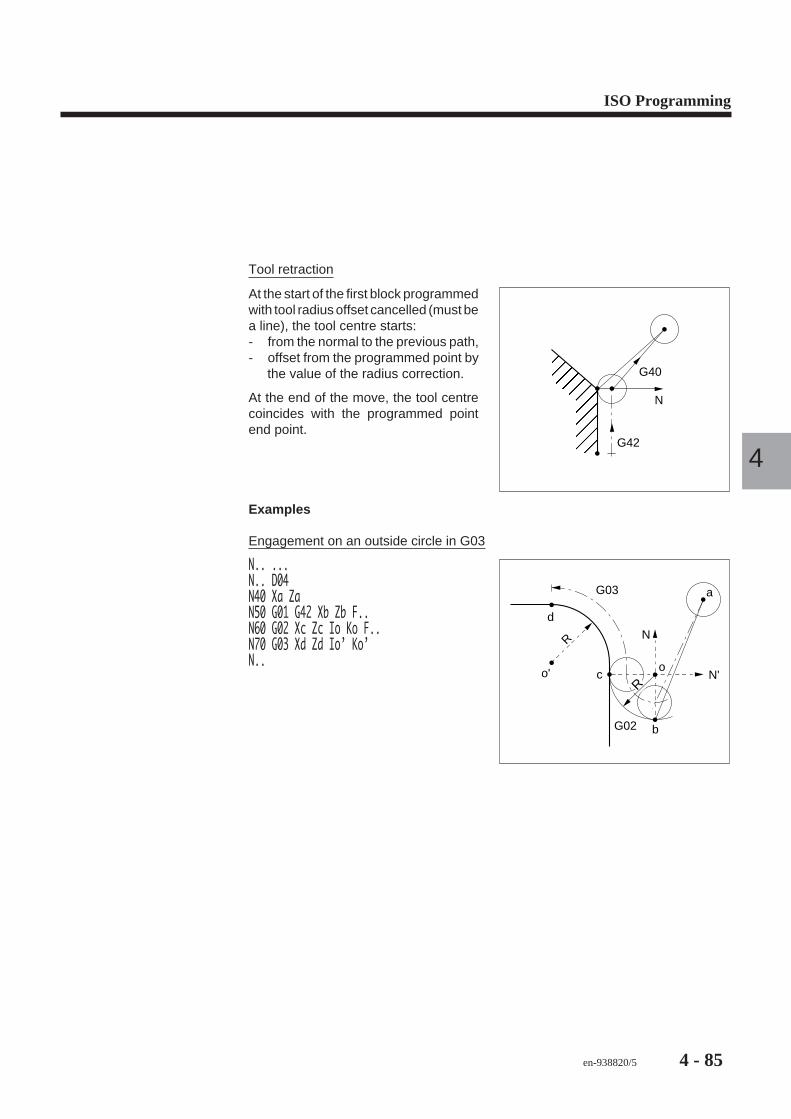
ISO Programming
en-938820/5 4 - 85
4
Tool retraction
<<<<<<<<<<<<=============>>>>>>>>>>>>>?????????????@@@@@@@@@@@@@AAAAAAAAAAAAABBBBBBBBBBBBBCCCCCCCCCCCCCDDDDDDDDDDDDDEEEEEEEEEEEEEFFFFFFFGGGGGGGHHHHHHHIIIIIIIJJJJJJJKKKKKKKLLLLLLLLMMMMMMMNNNNNNNOOOOOOO G42
N
G40
At the start of the first block programmedwith tool radius offset cancelled (must bea line), the tool centre starts:- from the normal to the previous path,- offset from the programmed point by
the value of the radius correction.
At the end of the move, the tool centrecoincides with the programmed pointend point.
Examples
Engagement on an outside circle in G03
G03
d
co
b
N'
N
G02
R
o'
a
R
N.. ...N.. D04N40 Xa ZaN50 G01 G42 Xb Zb F..N60 G02 Xc Zc Io Ko F..N70 G03 Xd Zd Io’ Ko’N..

4 - 86 en-938820/5
Contouring an external profile with right radius correction
30
85
95
75
10 20
ø 3
0
ø 5
0
ø 5
0
ø 5
0
ø 3
0
ø 3
0
R5
Unspecified radii = Tool radius
Machining paths (finishing)
R = 4
a
3
bdef
g
hi
j
5 c
OP Z
X

ISO Programming
en-938820/5 4 - 87
4
%37N10 G00 G52 X.. Z.. Tool change positionN20 T03 D03 M06 (COPYING TOOL R=4)N30 S900 M40 M04N40 G95 F0.2N50 G00 X30 Z102 Point a, right radius offsetN60 G92 S3500N70 G96 S200N80 G01 Z85 Point bN90 X50 Point cN100 X30 Z75 Point dN110 Z70 Point eN120 G02 X30 Z60 R5 F0.05 Point fN130 G01 X50 F0.2 Point gN140 X30 Z40 Point hN150 Z30 Point iN160 X60 Point jN170 G97 S900N180 G00 G40 G52 X.. Z.. M05 Radius offset cancelN190 M02

4 - 88 en-938820/5
Machining a groove by reciprocating cuts with alternating radius correction(G41-G42)
c
OP
ZX
d
g
b
e
f
ø 6
0
10
a
ø 3
0
30 10
G00 G42
%85N10 G00 G52 X.. Z.. Tool change positionN20 T01 D01 M06 (COPYING TOOL R=4)N30 S900 M40 M04N40 G95 F0.1N50 G00 G42 X80 Z-10 Point a, right correctionN60 G92 S3000N70 G96 S100N80 G01 X50 Point bN90 Z-40 F0.2 Point cN100 G41 X40 F0.1 Point d, left correctionN110 Z-10 Point eN120 G42 X30 Point f, right correctionN130 Z-40 F.2 Point gN140 X80N150 G97 S900N160 G00 G40 G52 X.. Z.. M05 Radius offset cancelN170 M02

ISO Programming
en-938820/5 4 - 89
4
External machining and internal contouring after tool retraction and positioning��FFFFFFGGGGGGHHHHHHIIIIIIJJJJJJKKKKKLLLLLMMMMMNNNNNNOOOOOOPPPPPPPPPPPPPPPPPPPPPPQQQQQQQQQQQQQQQQQQQQQQRRRRRRRRRRRRRRRRRRRRRRSSSSSSSSSSSSSSSSSSSSSSTTTTTTTTTTTTTTTTTTTTTTUUUUUUUUUUUUUUUUUUUUUUVVVVVVVVVVVVVVVVVVVVVWWWWWWWWWWWWWWWWWWWWWXXXXXXXXXXXXXXXXXXXXXYYYYYYYYYYYYYYYYYYYYYZZZZZZZZZZZZZZZZZZ[[[[[[[[[[[[[[[[[[\\\\\\\\\\\\\\\\\\\]]]]]]]]]]]]]]]]]]]^^^^^^^^^^^^^^^^^^^___________________```````````````````aaaaaaaaaaaaaaaaaaabbbbbbbbbbbbbbbbbbbccccccccccccccccccc
30
5x45 degrees
ø 8
0
ø 4
0
1x45 degrees
50
Hol
e di
a. 3
6
Machining paths
OP
X
Z
���������������������������������������������������������������������������������������������������������������������������������������������������������������������������������������������������������������������� ����������������������������������������ZZZZZZZZZZZZZZZZZZ[[[[[[[[[[[[[[[[[[\\\\\\\\\\\\\\\\\\]]]]]]]]]]]]]]]]]]^^^^^^^^^^^^^^^^^^__________________``````````````````aaaaaaaaaaaaaaaaaabbbbbbbbbbbbbbbbbbcccccccccccccccccc
1 5
2
d a
c
e
Ibh
gf

4 - 90 en-938820/5
%72N10 G00 G52 X.. Z.. Tool change positionN20 T01 D01 M06 (OUTSIDE TOOL R=0.8)N30 S900 M40 M04N40 G95 F0.12N50 G00 G41 X84 Z50 Point a, left correctionN60 G92 S3500N70 G96 S180N80 G01 X30 Point bN90 G00 G42 X60 Z55 Point c, right correctionN100 G01 X84 Z43 F0.08 Point dN110 G97 S900N120 G00 G40 G52 X.. Z.. Radius offset cancelN130 T07 D07 M06 (BORING TOOL R=0.4)N140 G41 X40 Z55 Point a, left correctionN150 G96 S100N160 G01 Z30 F0.1 Point fN170 X38 Point gN180 X34 Z28 Point hN190 G00 Z55 Point iN200 G97 S900N210 G40 G52 X.. Z.. M05 Radius offset cancelN220 M02

ISO Programming
en-938820/5 4 - 91
4
4.9 Basic Cycles
4.9.1 Cancellation of a Canned Cycle
G80 Canned cycle cancel.
This function cancels canned cycles.
Syntax
N.. G80
G80 Canned cycle cancel.
Properties of the Function
Function G80 is modal. It is the default function.
Cancellation
Modal function G80 is cancelled by one of functions G64, G81-G85, G87 or G89.
Example
N..N110 G00 X.. Z.. Tool positioningN120 G94 (or G95) F..N130 G83 Z-10 P8 Drilling cycleN140 G80 G00 G52 X.. Z.. Cycle cancelN..

4 - 92 en-938820/5
4.9.2 Constant Pitch Thread Chasing Cycle
X
Z
K
XZ
R
P
Q
G33 Constant pitch threadchasing cycle.
This function is used for cutting parallel,tapered or scroll threads.
The threads can be single or multiplestart and can be cut by straight or angularpenetration.
The consecutive passes are carried outwith reducing depths of cut.
Syntax
N.. G33 X.. Z.. K..[EA..][EB..]P..[Q..][R..][F..][S..] / [ES..]
G33 Constant pitch thread chasing cycle.
X.. Z.. Tool position at the end of thread cutting with respect tothe programme origin.
K.. Pitch in the thread cutting axis (X or Z) in mm.
EA.. Angle for tapered thread (see Fig. 5).- The default value of EA = 0: parallel thread cutting- EA90: scroll thread cutting.
EB.. Tool penetration angle (see Figs. 3 and 4)- The default value of EB = 0: straight penetration.- EB > 0: penetration down the thread flank in the
direction of machining.- EB < 0: penetration down the thread flank
opposite the machining direction.
P.. Total thread depth (including Q).
Q.. Depth of the final sizing pass (included in P)- Default no sizing pass (omit Q..).- Q = 0: spring cut required.

ISO Programming
en-938820/5 4 - 93
4
R.. Length of the tool retraction slope at the end of a pass(in the thread cutting axis) (see Figs. 1 and 2).- The default value of R = 0: retraction perpendicular
to the thread cutting axis.
F.. Number of thread starts (format F01) (see Fig. 6).- Default single start.
S../ES.. Number of passes (format S02 or ES02) (not includingpass Q), default 1 pass:- S..: Passes with reduced depth of cut,- ES..: Constant value passes.
Property of the Function
Function G33 is nonmodal.
Cancellation
Function G33 is cancelled at the end of the block.
Notes
The modal functions present before the G33 cycle are restored after execution of thecycle.
The thread pitch is applied to the thread cutting axis (axis on which the movement islargest).
During the cycle, spindle speed override is inhibited (value forced to 100 per cent).
REMARK The maximum possible pitch is limited by the feed rate in mm/minacceptable by the machine (feed rate = pitch x rotation speed). Referto the machine manufacturer’s documentation.
Thread cutting start point
X
Z
XZ
g
g
The tool must be backed off from thematerial by a clearance (g).
The clearance in the axis of penetrationis mandatory. If the tool positioning andend of thread cutting values in the axis ofpenetration are the same, the systemwill generate an error message.

4 - 94 en-938820/5
Cycle Steps
The steps below are given for information. The thread cutting cycle contains only themain parameters.
N.. ...N220 G00 Xa Za Rapid to start of thread cuttingN230 G33 Xb Zb K.. P.. S..N..
X
Z
1
23
5
4b
a6
Step 1: Tool positioning in X and Z to thethread cutting start point (point a).
Step 2: Rapid advance in the axis ofpenetration (first pass).
Step 3: Execution of the first pass in thethread cutting axis Z (point Zb).
Step 4: Retraction along X (point Xb).
Step 5: Rapid retraction of the penetrationaxis.
Step 6: Rapid return to the thread cuttingstart point.
Successive passes are executed in thesame way as steps 2 to 6 and may befollowed by a spring pass.

ISO Programming
en-938820/5 4 - 95
4
Tool retraction slope at the end the pass defined by R
Thread cutting without retraction slope Thread cutting with retraction slope
XZ
Ro
FIGURE 1
R . .
XZ
FIGURE 2
Penetration defined by EB
Thread cutting by straight penetration Thread cutting by penetration down the thread flank
EB0
FIGURE 3
EB EB
EB > 0
Machiningdirection
FIGURE 4

4 - 96 en-938820/5
Tapered thread cutting, angle defined by EA
Angle > 0°
Thread cutting axis
Angle < 0°
Thread cutting axis
FIGURE 5The value of EA is positive in thecounterclockwise direction, modulo 180degrees.
i.e. -45 deg < EA < 45 deg for:- Z thread cutting axis- X penetration axis.
I.e. EA > 45 deg or EA < -45 deg for:- Z axis of penetration- X thread cutting axis.
Multiple start thread cutting
dFIGURE 6The offset «d» (pitch) corresponding to
each start is in the direction opposite thethread cutting direction.
Each start will be completed at one depthbefore continuing to the next pass depth.
Reminders
Determination of the pass depth (P) for ISO threads.
External thread: 0.613 x pitch
Internal thread: 0.577 x pitch
Determination of the approximate number of passes (S)
S = P x 7
Approximate number of passes (integer)
Pass depth
Coefficient

ISO Programming
en-938820/5 4 - 97
4
Examples
Cutting of external tapered thread (5 deg)
R
OP Z
X 30°Q
P
ab
N.. ...N140 T09 D09 M06 (THREAD CUTTING TOOL, PITCH=1 RH THREAD)N150 G97 S1000 M40 M03N160 G00 Xa Za Start of thread cuttingN170 G33 Xb Zb K1 EA175 EB30 P0.61 Q0.02 R4 S5N.. ...

4 - 98 en-938820/5
Cutting of front threads
POP Z
XFFFFFFFGGGGGGGGHHHHHHHIIIIIIIJJJJJJJKKKKKKKLLLLLLLMMMMMMMNNNNNNNOOOOOOOPPPPPPPPPPPPPPPPPPPPPQQQQQQQQQQQQQQQQQQQQQRRRRRRRRRRRRRRRRRRRRRSSSSSSSSSSSSSSSSSSSSSTTTTTTTTTTTTTTTTTTTTTUUUUUUUUUUUUUUUUUUUUUVVVVVVVVVVVVVVVVVVVVVWWWWWWWWWWWWWWWWWWWWWXXXXXXXXXXXXXXXXXXXXXYYYYYYYYYYYYYYYYYYYYYZZZZZZZZZZZZZ[[[[[[[[[[[[[\\\\\\\\\\\\\]]]]]]]]]]]]]^^^^^^^^^^^^^_____________`````````````aaaaaaaaaaaaaabbbbbbbbbbbbbbccccccccccccc 60
ø 3
0ø
100
N.. ...$ FRONT THREAD ALONG XN140 T05 D05 M06 (TOOL R=2)N150 G97 S200 M40 M03N160 G00 X110 Z64 Point a, start of thread cuttingN170 G33 X20 Z60 K4 EA90 P2 Q0 S14N..

ISO Programming
en-938820/5 4 - 99
4
4.9.3 Sequenced Thread Cutting
Pitch
Z
X
Pitc
h
G38 Sequenced thread cutting.
This functions allows the execution ofseveral consecutive thread cuttingblocks.
The threads can be cylindrical or tapered.
Syntax
N.. G38 X.. Z.. K..
G38 Sequenced thread cutting.
X.. Z.. Tool position at the end of thread cutting with respect tothe programme origin.
K.. Pitch in the thread cutting axis (X or Z) in mm.
Property of the Function
Function G38 is modal.
Cancellation
Function G38 is cancelled by one of functions G00, G01, G02 or G03.
Notes
Different pitches (K) can be programmed in consecutive thread cutting blocks withG38.
The thread pitch is applied to the thread cutting axis (axis on which the movement islargest).
The consecutive passes, to obtain the required depth, can be programmed bysubroutine calls (see Sec. 4.11.1).
During execution of the cycle, spindle speed override by potentiometer is inhibited(value forced to 100 percent).

4 - 100 en-938820/5
Function G38 must be programmed:- without miscellaneous functions (M) in the cycle blocks,- without use of constant surface speed (nor retract in step for successive passes).
REMARK The maximum possible pitch is limited by the feed rate in mm/minacceptable by the machine (feed rate = pitch x rotation speed). Referto the machine manufacturer’s documentation.
Example
Sequenced external thread cutting
K4
OP Z
X
K6
K8e
dc
b a
N.. ...N100 T04 D04 M06 (TOOL R=2)N110 G97 S400 M40 M03N120 G00 Xa Za Approach pointN130 G38 Xb Zb K4 Cycle with 4 mm pitchN140 Xc Zc K6 Cycle with 6 mm pitchN150 Xd Zd K8 Cycle with 8 mm pitchN160 G00 Xe Ze Cycle cancelledN..

ISO Programming
en-938820/5 4 - 101
4
4.9.4 Drilling, Boring and Tapping Cycles
4.9.4.1 General
<<<<<<<<<<<============>>>>>>>>>>>>????????????@@@@@@@@@@@AAAAAAAAAAABBBBBBBBBBBCCCCCCCCCCCDDDDDDDDDDDEEEEEEEEEEEFFFFFFFFFFFFFFFFFGGGGGGGGGGGGGGGGGHHHHHHHHHHHHHHHHHIIIIIIIIIIIIIIIIIJJJJJJJJJJJJJJJJJKKKKKKKKKKKKKKKKKLLLLLLLLLLLLLLLLLMMMMMMMMMMMMMMMMMNNNNNNNNNNNNNNNNNOOOOOOOOOOOOOOOOOPPQQRRSSSTTTUUUVVWWXXYYZOP
OP
G8x Machining cycles in the toolaxis.
Axes programmable with the basic cy-cles:- primary axes X, Z,- secondary axes U, W,- rotary axes A or C are used only for
positioning when the machine isequipped with them.
Syntax
N.. G8x X.. / Z.. [ER..] [EH..]
G8x Machining cycle.
X.. / Z.. End point on the machining axis.
ER.. Dimension of the approach (or retraction) plane in themachining axis.
EH.. Dimension of the impact plane in the machining axis.
Properties of the Functions
Functions G8x are modal.
Cancellation
Functions G8x are cancelled by another function G8x or by functions G64, G65, G66.

4 - 102 en-938820/5
Notes
When a cycle (G8x) is programmed, the system must be in state G40 (G41 or G42tool radius offset cancelled).
! CAUTION
The use of programme variables L900 to L959 (see Chapter 6) is not recommended in aprogramme including canned cycles, since some of these variables could be overwritten
when a cycle is called.
Dimensions ER and EH
Dimension ER of the approach (or retraction) plane on the machining axis is assignedto the primary axis (Z) or the secondary axis (W) programmed last.
Dimension EH of the impact plane on the machining axis is assigned to the primaryaxis (Z or X) or the secondary axis (W or U) programmed last.
EH must always be programmed in the same block of the cycle as ER.
Cycle steps with ER (without EH)
((((((()))))))*******+++++++,,,,,,,-------.......////////00000001111111222222222222222222333333333333333333444444444444444444555555555555555555666666666666666666777777777777777777888888888888888888999999999999999999::::::::::::::::::;;;;;;;;;;;;;;;;;;<<<<<<<=======>>>>>>>???????@@@@@@@AAAAAAAABBBBBBBBCCCCCCCDDDDDDDEEEEEEE32ER . .
Z (or X)
1
Step 1: Rapid positioning (linear orcircular) in the plane then on ER..
Step 2: Tool penetration to the valueprogrammed on the tool axis (Z).
Step 3: Retraction along the tool axis (Z)up to ER..
ER.. not programmed:The previous value programmed on the Z axis is used for approach.
ER.. programmed alone:The tool is positioned in the Z axis.

ISO Programming
en-938820/5 4 - 103
4
Cycle steps with EH and ER
<<<<<=====>>>>????@@@@AAAABBBBBCCCCCDDDDDEEEEEFFFFFFFFFFFFFFFFFFFFGGGGGGGGGGGGGGGGGGGGHHHHHHHHHHHHHHHHHHHHIIIIIIIIIIIIIIIIIIIJJJJJJJJJJJJJJJJJJJKKKKKKKKKKKKKKKKKKKLLLLLLLLLLLLLLLLLLLMMMMMMMMMMMMMMMMMMMNNNNNNNNNNNNNNNNNNNOOOOOOOOOOOOOOOOOOOPPPPPPPPPPPPPQQQQQQQQQQQQQRRRRRRRRRRRRRSSSSSSSSSSSSSTTTTTTTTTTTTTUUUUUUUUUUUUUUVVVVVVVVVVVVVVWWWWWWWWWWWWWWXXXXXXXXXXXXXYYYYYYYYYYYYYZ (or X)
3
2
ER . .
1
EH . .
Step 1: Rapid linear positioning in theaxis then on EH..
Step 2: Tool penetration down to thevalue programmed on the tool axis (Z orX).
Step 3: Retraction along the tool axis (Zor X) up to ER..
EH and ER.. programmed:EH differentiates between the impact plane and the backoff plane.
EH.. not programmed and ER.. programmed:The value of ER is used (ER = EH).
REMARK The above descriptions of the cycle steps with ER alone and with ERand EH take into account only the start and end planes. For the detailof these steps, refer to the cycle concerned.

4 - 104 en-938820/5
4.9.4.2 Centre Drilling Cycle
222233334444555566667777888999:::;;;<<<<<<<<<<<<<<<<<<<===================>>>>>>>>>>>>>>>>>>>???????????????????@@@@@@@@@@@@@@@@@@@AAAAAAAAAAAAAAAAAAABBBBBBBBBBBBBBBBBBBCCCCCCCCCCCCCCCCCCCDDDDDDDDDDDDDDDDDDDEEEEEEEEEEEEEEEEEEEFFFFFFFFFFFFFGGGGGGGGGGGGGGHHHHHHHHHHHHHHIIIIIIIIIIIIIIJJJJJJJJJJJJJKKKKKKKKKKKKKLLLLLLLLLLLLLMMMMMMMMMMMMMNNNNNNNNNNNNNOOOOOOOOOOOOO F . .
OP
X
Z
G81 Centre drilling cycle.
Syntax
N.. G81 X.. / Z.. [ER..] [EH..]
G81 Centre drilling cycle.
X.. / Z.. End point on the machining axis.
ER.. Dimension of the retraction plane on the machining axis.
EH.. Impact plane in the machining axis.
Property of the Function
Function G81 is modal.
Cancellation
Function G81 is cancelled by one of functions G80, G82-G85, G87, G89 or functionsG64, G65, G66.

ISO Programming
en-938820/5 4 - 105
4
Cycle Steps
Step 1: Fast positioning on the machining axis.
Step 2: Infeed at feed rate F..
Step 3: Outfeed at high speed in the tool axis.
Example
Execution of centre drilling. ����������������������������PPPPPPPPPPPQQQQQQQQQQQRRRRRRRRRRRRSSSSSSSSSSSSTTTTTTTTTTTTUUUUUUUUUUUVVVVVVVVVVVWWWWWWWWWWWXXXXXXXXXXXYYYYYYYYYYYZZZZZZZZZZZZZZZZZZ[[[[[[[[[[[[[[[[[[\\\\\\\\\\\\\\\\\\]]]]]]]]]]]]]]]]]]^^^^^^^^^^^^^^^^^^__________________``````````````````aaaaaaaaaaaaaaaaaabbbbbbbbbbbbbbbbbbcccccccccccccccccc
OP
Z a
X
8
N.. ...N50 G00 Xa ZaN60 G94 (or G95) F..N70 G81 Z-8N80 G80 G00 X.. Z..N..or
N..N50 G94 (or G95) F..N60 G81 Xa ERa Z-8N70 G80 G00 X.. Z..N..

4 - 106 en-938820/5
4.9.4.3 Counterboring Cycle
OP
X
F . .
EF
����� ����� !!!! """" #### $$$$ %%%% &&&&& ''''' ((((((((((((((((((( ))))))))))))))))))) ******************* +++++++++++++++++++ ,,,,,,,,,,,,,,,,,,, ------------------- ................... /////////////////// 0000000000000000000 1111111111111111111 22222222222 33333333333 44444444444 55555555555 66666666666 7777777777 8888888888 9999999999 :::::::::: ;;;;;;;;;;;Z
G82 Counterboring cycle.
Syntax
N.. G82 X.. / Z.. [ER..] [EH.] EF..
G82 Counterboring cycle.
X.. / Z.. End point on the machining axis.
ER.. Dimension of the retraction plane on the machining axis.
EH.. Impact plane in the machining axis.
EF.. Mandatory dwell expressed in seconds (maximum99.99 s, format EF022).
Property of the Function
Function G82 is modal.
Cancellation
Function G82 is cancelled by one of functions G80, G81, G83-G85, G87, G89 orfunctions G64, G65, G66.

ISO Programming
en-938820/5 4 - 107
4
Cycle Steps
Step 1: Fast positioning in the machining axis.
Step 2: Infeed at feed rate F..
Step 3: Dwell at the end of drilling (or boring).
Step 4: Outfeed at high speed on the tool axis.
Example
Execution of counterboring
�� !"#$%' ((((((((((((((( ))))))))))))))) *************** +++++++++++++++ ,,,,,,,,,,,,,,, --------------- ............... /////////////// 000000000000000 111111111111111 2222222 3333333 4444444 5555555 66666666 77777777 88888888 99999999 :::::::: ;;;;;;;;5
aOP
X
Z
N.. ...N50 G00 Xa ZaN60 G94 (or G95) F..N70 G82 Z-5 EF2N80 G80 G00 X.. Z..N..or
N..N50 G94 (or G95) F..N60 G82 Xa ERa Z-5 EF2N70 G80 G00 X.. Z..N..

4 - 108 en-938820/5
4.9.4.4 Peck Drilling Cycle
<<<<<<<<<<==========>>>>>>>>>>>???????????@@@@@@@@@@AAAAAAAAAABBBBBBBBBBCCCCCCCCCCDDDDDDDDDDEEEEEEEEEEFFFFFFFFFFFFFFGGGGGGGGGGGGGGHHHHHHHHHHHHHHIIIIIIIIIIIIIIJJJJJJJJJJJJJJKKKKKKKKKKKKKKKLLLLLLLLLLLLLLLMMMMMMMMMMMMMMMNNNNNNNNNNNNNNNOOOOOOOOOOOOOOOPQ
OP
ZX
F . .
G83 Peck drilling cycle.
This cycle can be used for drilling in theX or Z axis
Syntax
N.. G83 X.. / Z.. [ER..] [EH..] [P..] / [ES..] [Q..] [EP..] [EF..]
G83 Peck drilling cycle.
X.. / Z.. End point on the machining axis.
ER.. Retraction plane on the machining axis.
EH.. Impact plane in the machining axis.
P.. Value of first peck.
ES.. Number of infeeds (pecks) at constant value(see Fig. 1).
Q.. Value of last peck.
EP.. Backoff after each peck (default 1 mm).
EF.. Dwell at the end of each peck.
Property of the Function
Function G83 is modal.
Cancellation
Function G83 is cancelled by one of functions G80-G82, G84, G85, G87 and G89 orfunctions G64, G65, G66.

ISO Programming
en-938820/5 4 - 109
4
Notes
If addresses P and Q are programmed, the consecutive pecks between P and Q aredegressive values.
At least one of arguments P and ES must be programmed or the system returns errormessage 889.
If the value of P is greater than delta Z, the system returns error message 881.
Notes related to ES (number of constant infeeds)
PPPPPPPPPPPPQQQQQQQQQQQQQRRRRRRRRRRRRRSSSSSSSSSSSSSTTTTTTTTTTTTTUUUUUUUUUUUUUVVVVVVVVVVVVVWWWWWWWWWWWWWXXXXXXXXXXXXXYYYYYYYYYYYYYZZZZZZZZ[[[[[[[[\\\\\\\\]]]]]]]^^^^^^^_______```````aaaaaaabbbbbbbbccccccccWith P and ES
Figure 1
Rem
aind
er/E
SP
������������������������������������������������ZZZZZZZZZZZZZ[[[[[[[[[[[[[\\\\\\\\\\\\\]]]]]]]]]]]]]^^^^^^^^^^^^^_____________`````````````aaaaaaaaaaaaabbbbbbbbbbbbbccccccccccccc
Dril
lings
/ES
ES alone
If P and ES are programmed:
The first infeed is equal to P and drillingis continued as a number ES of infeeds.
If ES is programmed alone (without P):
All the drilling is executed as a numberES of infeeds.
Cycle Steps
The steps below are given as an illustration. The number of steps depends on thevalues programmed in the cycle.
Step 1: Fast positioning in the machining axis.
Step 2: First peck to depth P.. in the tool axis at the machining feed rate.
Possible dwell at the end of the peck.
Rapid retraction to the start point.
Rapid infeed to 1 mm (or EP..) above depth P..
Step 3: Second peck at feed rate.
Possible dwell at the end of the peck.
Rapid retraction to the start point.
Rapid infeed to 1 mm (or EP..) above the previous peck.
Steps 4 and 5: Pecks and retractions same as step 3.
Step 6: Peck to depth Q.. at feed rate.
Step 7: Rapid retraction to the start point.
Possible dwell G04 F.. in the start point.

4 - 110 en-938820/5
PPPPPPPPPPPPPPPPPPQQQQQQQQQQQQQQQQQQRRRRRRRRRRRRRRRRRRSSSSSSSSSSSSSSSSSSTTTTTTTTTTTTTTTTTTUUUUUUUUUUUUUUUUUUVVVVVVVVVVVVVVVVVVWWWWWWWWWWWWWWWWWXXXXXXXXXXXXXXXXXYYYYYYYYYYYYYYYYYZZZZZZZZZZZZZZZZZ[[[[[[[[[[[[[[[[[[\\\\\\\\\\\\\\\\\\]]]]]]]]]]]]]]]]]]^^^^^^^^^^^^^^^^^^__________________``````````````````aaaaaaaaaaaaaaaaaabbbbbbbbbbbbbbbbbbccccccccccccccccccClearance
3
PQ
4
5
6
2
7
X or Z
X or Z
(possibly G04)
EF
EF
EF
EF
EF
1

ISO Programming
en-938820/5 4 - 111
4
4.9.4.5 Tapping Cycle
22223333444455556666777788889999::::;;;;<<<<<<<<<<<<<<<<<<==================>>>>>>>>>>>>>>>>>>??????????????????@@@@@@@@@@@@@@@@@@AAAAAAAAAAAAAAAAAABBBBBBBBBBBBBBBBBBCCCCCCCCCCCCCCCCCCDDDDDDDDDDDDDDDDDDEEEEEEEEEEEEEEEEEEFFFFFFFFFFGGGGGGGGGGHHHHHHHHHHHIIIIIIIIIIIJJJJJJJJJJJKKKKKKKKKKLLLLLLLLLLMMMMMMMMMMNNNNNNNNNNOOOOOOOOOOOP Z
X
F . .
F . .
EFDirection of rotationReversal
of thedirection
of rotation
G84 Tapping cycle.
This cycle is used to tap a hole with afloating tap-holder.
Syntax
N.. G84 X.. / Z.. [ER..] [EH..] EF..
G84 Tapping cycle.
X.. / Z.. End point on the machining axis.
ER.. Dimension of the retraction plane on the machining axis.
EH.. Impact plane in the machining axis.
EF.. Dwell expressed in seconds (maximum 99.99 s, formatEF022, default 1 second).
Property of the Function
Function G84 is modal.
Cancellation
Function G84 is cancelled by one of functions G80-G83, G85, G87, G89 or functionsG64, G65, G66.

4 - 112 en-938820/5
Notes
In this tapping cycle, since feed is not slaved to spindle rotation, the tap must befloating to compensate for position errors.
During execution of the cycle, feed rate override by potentiometer is inhibited (valueforced to 100 percent).
Determination of the feed rate in mm/min
F.. = Tap pitch (in mm) x spindle speed rotation (revolutions/minute).
Cycle Steps
Step 1: Fast positioning in the machining axis.
Step 2: Infeed at the specified feed rate F..
Step 3: Reversal of the direction of rotation at the end of tapping.
Step 4: Dwell at the end of tapping.
Step 5: Outfeed at the specified feed rate F.. along the tool axis.
Example
Execution of one M8 tapping, pitch 1.25. �������������������� !!!!!!!!!!""""""""""###########$$$$$$$$$$$%%%%%%%%%%&&&&&&&&&&''''''''''((((((((((((((((((()))))))))))))))))))*******************+++++++++++++++++++,,,,,,,,,,,,,,,,,,,-------------------...................///////////////////000000000000000000011111111111111111112222222333333344444445555555666666777777888888999999:::::::;;;;;;;OP
X
a
20
Z
N.. ...N40 S300 M41 M03N50 G00 Xa ZaN60 G94 (or G95) F..N70 G84 Z-20 EF1N80 G80 G00 X.. Z..N..or
N..N50 G94 F375N60 G84 Xa ERa Z-20 EF1N70 G80 G00 X.. Z..N..

ISO Programming
en-938820/5 4 - 113
4
4.9.4.6 Rigid Tapping Cycle
<<<<<<<<<<<===========>>>>>>>>>>>???????????@@@@@@@@@@@AAAAAAAAAAABBBBBBBBBBBCCCCCCCCCCCDDDDDDDDDDDEEEEEEEEEEEFFFFFFFFFFFFFGGGGGGGGGGGGGHHHHHHHHHHHHHIIIIIIIIIIIIIJJJJJJJJJJJJJKKKKKKKKKKKKKLLLLLLLLLLLLLMMMMMMMMMMMMMNNNNNNNNNNNNNOOOOOOOOOOOOO Reversal of thedirection of rotation
KxSDirection
of rotation
X/ZG84 Rigid tapping cycle.
This cycle slaves the tap to the spindlerotation. The feed rate is automaticallycalculated from the actual spindle speedand pitch.
This cycle can be used to programmetapping in the X or Z axes.
Syntax
N.. G84 X.. / Z.. K.. [ER..] [EH..] [EK..]
G84 Tapping cycle.
X.. / Z.. End point on the machining axis.
K.. Tap pitch in mm (K specifies that tapping is rigid).
ER.. Retraction plane in the machining axis.
EH.. Impact plane in the machining axis.
EK.. Spindle outfeed/infeed ratio (the default value of EK=1).
Property of the Function
Function G84 is modal.
Cancellation
Function G84 is cancelled by one of functions G80-G83, G85, G87 and G89 orfunctions G64, G65, G66.

4 - 114 en-938820/5
Notes
When the cycle is called, the tool axis (X or Z) is coupled with spindle rotation.
When the tapping axis is not located on the centre line of rotation of the part, themachine must be equipped with:- a C axis,- a measured auxiliary spindle.
During execution of the cycle:- the following error on the tapping axis is cancelled during feed at constant speed,- feed rate and spindle speed override by potentiometer is inhibited (value forced
to 100 percent).
In the end-of-tapping region, the spindle is decelerated then rotation is reversed.
At the end of the cycle, the spindle is returned to its initial state.
Rigid tapping can be carried out over several penetrations, but this requiresprogramming several consecutive blocks.
Rigid tapping can be carried out over several penetrations, but this requiresprogramming several consecutive blocks.
With rigid tapping, the system returns error message 899 in the following cases:- use with an axis group number above 5,- use with a spindle number above 2,- the axis group does not control the spindle used or does not provide its
measurement.
Tapping Clearance
Before starting the cycle, sufficient clearance must be provided to allow the tappingaxis to reach correct speed before impacting the material. This clearance dependson the required tapping speed and the acceleration allowed on the axis. The followingchart can be used to approximate the clearance required.
Use of the chart for tapping an M10 hole (pitch = 1.5 mm), for instance:- rotation speed = 320 rpm,- axis feed rate = 480 mm/min or 0.48 m/min,- acceleration = 0.5 m/s2.

ISO Programming
en-938820/5 4 - 115
4
Required clearance read on the chart: approximately 4 mm
Clearancein mm
Speed onthe axisin m/min
10
8
4
2
00,5 1
0,5 m/s2
1 m/s2
2 m/s2
Cycle Steps
FFFFFFFFFFGGGGGGGGGGHHHHHHHHHHHIIIIIIIIIIIJJJJJJJJJJJKKKKKKKKKKKLLLLLLLLLLLMMMMMMMMMMMNNNNNNNNNNOOOOOOOOOOPPPPPPPPPPPPPPPPPQQQQQQQQQQQQQQQQQRRRRRRRRRRRRRRRRRSSSSSSSSSSSSSSSSSTTTTTTTTTTTTTTTTTUUUUUUUUUUUUUUUUUVVVVVVVVVVVVVVVVVWWWWWWWWWWWWWWWWWXXXXXXXXXXXXXXXXXYYYYYYYYYYYYYYYYYZZZ[[[\\\]]]^^^___```aabbbccc5
6 7 8
4 3 2
1
X/Z
Step 1: Rapid to start of hole (provide clearance).
Step 2: Infeed with acceleration of the spindle speed and feed rate.
Step 3: Feed at constant speed.
Step 4: Deceleration before reaching depth.
Step 5: Reversal of the direction of rotation.
Step 6: Retraction with acceleration over a distance equal to the deceleration.
Step 7: Feed at constant speed.
Step 8: Return of the spindle to the initial state.

4 - 116 en-938820/5
Examples
Execution of one M10 hole, pitch 1.50
FFFFFFFFGGGGGGGGHHHHHHHIIIIIIIJJJJJJJKKKKKKKLLLLLLLMMMMMMMMNNNNNNNNOOOOOOOOPPPPPPPPPPPPPPPPQQQQQQQQQQQQQQQQRRRRRRRRRRRRRRRRSSSSSSSSSSSSSSSSTTTTTTTTTTTTTTTTUUUUUUUUUUUUUUUUVVVVVVVVVVVVVVVVWWWWWWWWWWWWWWWWXXXXXXXXXXXXXXXXYYYYYYYYYYYYYYYYZZ[[\\]]^^__``aabbccOP
30
ZX
a
N.. ...N130 G97 S200 M41 M03N140 G00 Xa ZaN150 G84 Z-30 K1.5 EK2N160 G80 G00 G52 X.. Z..
Execution of one tapped hole with several consecutive penetrations
FFFFFFFFFFFGGGGGGGGGGGHHHHHHHHHHHIIIIIIIIIIJJJJJJJJJJJKKKKKKKKKKKLLLLLLLLLLLMMMMMMMMMMMNNNNNNNNNNNOOOOOOOOOOOPPPPPPPPPPPPPPPPPPPQQQQQQQQQQQQQQQQQQQRRRRRRRRRRRRRRRRRRRSSSSSSSSSSSSSSSSSSSTTTTTTTTTTTTTTTTTTTUUUUUUUUUUUUUUUUUUUVVVVVVVVVVVVVVVVVVVWWWWWWWWWWWWWWWWWWWXXXXXXXXXXXXXXXXXXXYYYYYYYYYYYYYYYYYYYZZZZ[[[[[\\\\\]]]]]^^^^^_____`````aaaaabbbbccccabd c
Z
N.. ...N240 G97 S400 M41 M03N250 G00 Xa ZaN260 G84 Zb K.. EK..N270 ZcN280 ZdN290 G80 G00 G52 X.. Z..N..

ISO Programming
en-938820/5 4 - 117
4
4.9.4.7 Boring Cycle
222222222222222223333333333333333344444444444444444555555555555555556666666666666666677777777777777777888888888888888899999999999999999:::::::::::::::::;;;;;;;;;;;;;;;;;<<<<<<<<<<<<<<<<<<===================>>>>>>>>>>>>>>>>>>>???????????????????@@@@@@@@@@@@@@@@@@@AAAAAAAAAAAAAAAAAAABBBBBBBBBBBBBBBBBBBCCCCCCCCCCCCCCCCCCDDDDDDDDDDDDDDDDDDEEEEEEEEEEEEEEEEEEOP
X
Z
F . .
G85 Boring cycle.
Syntax
N.. G85 X.. / Z.. [ER..] [EH..] [EF..]
G85 Boring cycle.
X.. / Z.. End point on the machining axis.
ER.. Dimension of the retraction plane on the machining axis.
EH.. Impact plane in the machining axis.
EF.. Retraction rate (default = feed rate F..).
Property of the Function
Function G85 is modal.
Cancellation
Function G85 is cancelled by one of functions G80-G84, G87 and G89 or functionsG64, G65, G66.

4 - 118 en-938820/5
Cycle Steps
Step 1: Fast positioning in the machining axis.
Step 2: Infeed at feed rate F..
Step 3: Outfeed at feed rate F.. along the tool axis.
Example
Execution of a bore. �� !!"#$%&'((((((((((((((((((()))))))))))))))))))*******************+++++++++++++++++++,,,,,,,,,,,,,,,,,,,-------------------...................///////////////////000000000000000000011111111111111111112222222222222223333333333333334444444444444455555555555555666666666666667777777777777788888888888888999999999999999:::::::::::::::;;;;;;;;;;;;;;;OP
Z
a
25
X
N.. ...N50 G00 Xa ZaN60 G94 (or G95) F..N70 G85 Z-25N80 G80 G00 X.. Z..N..or
N..N50 G94 (or G95) F..N60 G85 Xa ERa Z-25N70 G80 G00 X.. Z..

ISO Programming
en-938820/5 4 - 119
4
4.9.4.8 Drilling Cycle with Chip Breaking
)*2222222222222222233333333333333333444444444444444445555555555555555566666666666666666777777777777777778888888888888888899999999999999999:::::::::::::::::;;;;;;;;;;;;;;;;;<<<<<<<<<<<<============>>>>>>>>>>>>????????????@@@@@@@@@@@@AAAAAAAAAAAABBBBBBBBBBBBCCCCCCCCCCCCDDDDDDDDDDDDEEEEEEEEEEEEPQ
OP
ZX
F . .
G87 Drilling cycle with chipbreaking.
This cycle is used to programmemachining in the X or Z axes.
Syntax
N.. G87 X.. / Z.. [ER..] [EH..] [P..] / [ES..] [Q..] [EP..] [EF..]
G87 Drilling cycle with chip breaking.
X.. / Z.. End point on the machining axis.
ER.. Retraction plane in the machining axis.
EH.. Impact plane in the machining axis
P.. Value of first infeed.
ES.. Number of infeeds at constant value (see Fig. 1)
Q.. Value of last infeed.
EP.. Backoff between two infeeds (default no backoff,EP = 0).
EF.. Dwell at the end of each infeed.
Property of the Function
Function G87 is modal.
Cancellation
Function G87 is cancelled by one of functions G80-G85 and G89 or functions G64,G65, G66.

4 - 120 en-938820/5
Notes
If addresses P and Q are programmed, the consecutive infeeds between P and Q aredegressive values.
At least one of arguments P and ES must be programmed or the system returns errormessage 889.
If the value of P is greater than delta Z, the system returns error message 881.
Notes related to ES (number of constant infeeds) ��������������������������PPQQRSSTTUUVVWWXXYYZZZZZZZZZZZZZ[[[[[[[[[[[[[\\\\\\\\\\\\\]]]]]]]]]]]]]^^^^^^^^^^^^^_____________`````````````aaaaaaaaaaaaabbbbbbbbbbbbbccccccccccccc
With P and ES
Rem
aind
er/E
SP �����������������������������������������������������������������������������������������������������������������������������������
ZZZZ[[[[[\\\\\]]]]^^^^____````aaaabbbbccccD
rillin
gs/E
S
ES alone
Figure 1If P and ES are programmed:
The first infeed is equal to P and drillingis continued as a number ES of infeeds.
If ES is programmed alone (without P):
All the drilling is executed as a numberES of infeeds.

ISO Programming
en-938820/5 4 - 121
4
Cycle Steps
The steps below are given as an illustration. The number of steps depends on thevalues programmed with the cycle.
FFFFFFFFFGGGGGGGGGHHHHHHHHHIIIIIIIIIIJJJJJJJJJJKKKKKKKKKLLLLLLLLLMMMMMMMMMNNNNNNNNNOOOOOOOOOPPPPPPPPPPPPPPPPPPPPPPPPQQQQQQQQQQQQQQQQQQQQQQQQRRRRRRRRRRRRRRRRRRRRRRRRSSSSSSSSSSSSSSSSSSSSSSSSTTTTTTTTTTTTTTTTTTTTTTTTUUUUUUUUUUUUUUUUUUUUUUUVVVVVVVVVVVVVVVVVVVVVVVWWWWWWWWWWWWWWWWWWWWWWWXXXXXXXXXXXXXXXXXXXXXXXYYYYYYYYYYYYYYYYYYYYYYYZZZZZZZZZZZZZZZZZZ[[[[[[[[[[[[[[[[[[\\\\\\\\\\\\\\\\\\]]]]]]]]]]]]]]]]]]^^^^^^^^^^^^^^^^^^___________________``````````````````aaaaaaaaaaaaaaaaaabbbbbbbbbbbbbbbbbbccccccccccccccccccClearance
PQ
EF
EF
EF
3
2
1
EF6
5
4
X or Z
X or Z
(possibly G04)
Step 1: Fast positioning in the machining axis.
Step 2: First infeed of depth P.. at programmed feed rate.
Possible dwell at the end of the infeed.
Steps 3 and 4: Consecutive infeeds and dwells as step 2.
Step 5: Infeed depth Q.. at the feed rate.
Possible dwell at the end of the peck.
Step 6: Rapid retraction in the tool axis.
Possible dwell G04 F.. at the start point.

4 - 122 en-938820/5
4.9.4.9 Boring Cycle with Dwell at the Bottom of the Hole
EF
FFFFFFFFFFFFFGGGGGGGGGGGGHHHHHHHHHHHHIIIIIIIIIIIIJJJJJJJJJJJJKKKKKKKKKKKKKLLLLLLLLLLLLLMMMMMMMMMMMMMNNNNNNNNNNNNNOOOOOOOOOOOOOPPPPPPPPPPPPPPPPPPQQQQQQQQQQQQQQQQQQRRRRRRRRRRRRRRRRRRSSSSSSSSSSSSSSSSSSTTTTTTTTTTTTTTTTTTUUUUUUUUUUUUUUUUUUVVVVVVVVVVVVVVVVVVWWWWWWWWWWWWWWWWWWXXXXXXXXXXXXXXXXXXYYYYYYYYYYYYYYYYYYZZZ[[[\\\]]]^^^___```aaabbbcccX
Z
F . .
F . .
OP
G89 Boring cycle with dwell at thebottom of the hole.
Syntax
N.. G89 X.. / Z.. [ER..] [EH..] EF..
G89 Boring cycle with dwell at the bottom of the hole.
X.. / Z.. End point on the machining axis.
ER.. Dimension of the retraction plane on the machining axis.
EH.. Impact plane in the machining axis.
EF.. Mandatory dwell expressed in seconds (maximum99.99 s, format EF022, the default value ofEF = 1 second).
Property of the Function
Function G89 is modal.
Cancellation
Function G89 is cancelled by one of functions G80-G85, G87 or functions G64, G65,G66.

ISO Programming
en-938820/5 4 - 123
4
Cycle Steps
Step 1: Fast positioning in the machining axis.
Step 2: Infeed at the feed rate F..
Step 3: Dwell at the end of boring
Step 4: Outfeed at the feed rate F.. along the tool axis.
Example
Execution of a bore.
<<<<<<<<<<<<<<<<=================>>>>>>>>>>>>>>>>>?????????????????@@@@@@@@@@@@@@@@@AAAAAAAAAAAAAAAABBBBBBBBBBBBBBBBCCCCCCCCCCCCCCCCDDDDDDDDDDDDDDDDEEEEEEEEEEEEEEEEFFFFFFFFFFFFFFFFFFFGGGGGGGGGGGGGGGGGGGHHHHHHHHHHHHHHHHHHHIIIIIIIIIIIIIIIIIIIJJJJJJJJJJJJJJJJJJJKKKKKKKKKKKKKKKKKKKLLLLLLLLLLLLLLLLLLLMMMMMMMMMMMMMMMMMMMNNNNNNNNNNNNNNNNNNNOOOOOOOOOOOOOOOOOOOOP
Z a
25
X
N.. ...N50 G00 Xa ZaN60 G94 (or G95) F..N70 G89 Z-25 EF1N80 G80 G00 X.. Z..N..or
N..N50 G94 (or G95) F..N60 G89 Xa ERa Z-25 EF1N70 G80 G00 X.. Z..N..

4 - 124 en-938820/5
4.9.4.10 Examples of Programming Cycles
Drilling in the Z axis (cycle G83 or G87)
2222222333333344444445555555666666677777778888888999999::::::;;;;;;;<<<<<<<<<<<<<<<<<<<<<<<<<<==========================>>>>>>>>>>>>>>>>>>>>>>>>>>??????????????????????????@@@@@@@@@@@@@@@@@@@@@@@@@@AAAAAAAAAAAAAAAAAAAAAAAAAABBBBBBBBBBBBBBBBBBBBBBBBBBCCCCCCCCCCCCCCCCCCCCCCCCCCDDDDDDDDDDDDDDDDDDDDDDDDDDDEEEEEEEEEEEEEEEEEEEEEEEEEEEFFFFFFFFFFFFFFFFFFFFFFFFFFFFGGGGGGGGGGGGGGGGGGGGGGGGGGGGHHHHHHHHHHHHHHHHHHHHHHHHHHHHIIIIIIIIIIIIIIIIIIIIIIIIIIIIJJJJJJJJJJJJJJJJJJJJJJJJJJJJKKKKKKKKKKKKKKKKKKKKKKKKKKKKLLLLLLLLLLLLLLLLLLLLLLLLLLLLMMMMMMMMMMMMMMMMMMMMMMMMMMMMNNNNNNNNNNNNNNNNNNNNNNNNNNNNOOOOOOOOOOOOOOOOOOOOOOOOOOOOPPPPPPPPPQQQQQQQQQRRRRRRRRRSSSSSSSSSTTTTTTTTTUUUUUUUUUVVVVVVVVVWWWWWWWWWXXXXXXXXXXYYYYYYYYYY 5
ab
20
50
OP Z
X
ø 2
2
%62N10...N.. G92 S3500N.. ...N120 T06 D06 M06 (CARBIDE DRILL D=22)N130 G97 S900 M40 M03N140 G00 X0 Z55 Point aN150 G96 X22 S100N160 G95 F0.15N170 G83 (or G87) Z20 P10 Q5 Point b, cycleN180 G97 S900N190 G80 G00 G52 X.. Z.. Cycle cancellationN..

ISO Programming
en-938820/5 4 - 125
4
Execution of two grooves in the X axis (cycle G83 or G87)
OP Z
X
b a
15
30
1
ø 5
8
ø 4
6
ø 5
0
%56N10...N.. G92 S3000N..N.. ...N220 T08 D08 M06 (GROOVING TOOL L=4)N230 G97 S900 M40 M04N240 G16 P+ Tool axis orientation on X+N250 G00 X60 Z-15 Point aN260 G96 S50N270 G95 F0.1N280 G83 (or G87) X50 P2 Q1 G04 F1 CycleN290 X46 Z-30 Point b, cycle repeatN300 G97 S900N310 G80 G16 R+ G00 G52 X.. Z.. Cycle cancellationN..

4 - 126 en-938820/5
Execution of three front grooves along the Z axis (cycle G82) with positioning ondifferent levels using ER
Grooves with radius 3, depth 3.������������������������������������������������������������������������FFFFFFFFFFFFFFFGGGGGGGGGGGGGGGHHHHHHHHHHHHHHHIIIIIIIIIIIIIIIJJJJJJJJJJJJJJJKKKKKKKKKKKKKKLLLLLLLLLLLLLLMMMMMMMMMMMMMMMNNNNNNNNNNNNNNNOOOOOOOOOOOOOOOPPPPPPPPPPPPPPPPPPPPPPPPPPPPPPQQQQQQQQQQQQQQQQQQQQQQQQQQQQQQRRRRRRRRRRRRRRRRRRRRRRRRRRRRRRSSSSSSSSSSSSSSSSSSSSSSSSSSSSSSTTTTTTTTTTTTTTTTTTTTTTTTTTTTTTUUUUUUUUUUUUUUUUUUUUUUUUUUUUUVVVVVVVVVVVVVVVVVVVVVVVVVVVVVWWWWWWWWWWWWWWWWWWWWWWWWWWWWWXXXXXXXXXXXXXXXXXXXXXXXXXXXXXYYYYYYYYYYYYYYYYYYYYYYYYYYYYYZZZZZZZZZZZZZZZZZZZZZZZZZZ[[[[[[[[[[[[[[[[[[[[[[[[[[\\\\\\\\\\\\\\\\\\\\\\\\\\]]]]]]]]]]]]]]]]]]]]]]]]]]^^^^^^^^^^^^^^^^^^^^^^^^^^__________________________``````````````````````````aaaaaaaaaaaaaaaaaaaaaaaaaabbbbbbbbbbbbbbbbbbbbbbbbbbccccccccccccccccccccccccccc
1
ø 3
0
ø 8
0
ab
ø 5
0
ø 7
0OP
Z
X
5
10
c
%72N10...N.. G92 S200N..N..N190 T06 D06 M06 (GROOVE CUTTER R3)N200 G97 S900 M04 M40N210 G00 Z10N220 G96 X80 S40N230 G95 F0.08N240 G82 X70 Z-3 ER1 EF2 Point a, cycleN250 X50 Z-13 ER-9 Point b, cycleN260 ER-4N270 X30 Z-8 EF1 Point c, cycleN280 G97 S900N290 G80 G00 G52 X.. Z.. Cycle cancellationN..

ISO Programming
en-938820/5 4 - 127
4
4.9.4.11 Table Summarising Cycles G81 to G89
G81 G82 G83 G84 G85 G87 G89
Centre drilling CounterboringPeck
drillingTapping Reaming
Drilling with
chip breaking
Boring with dwell
in bottom of hole
Work Rapid thenwork with nconsecutivepenetrations
(P, Q)
WorkDownward Work Work Workwith n
consecutivepenetrations
(P, Q)
Work
Programmedby ES
Number of constant infeeds
Retraction after
infeed
HOLE
BOTTOM
Dwell Programmed by EF
Programmed by EF on a combination
machine used for turning
Programmed by EF
Spindle
Retraction
in the plane
Outfeed Rapid Rapid Rapid Work Workrate of other feed rate if EF present
WorkRapid atthe end ofpenetration
CYCLES
SEQUENCEOF MOVEMENTS
Reversalof rotation
Programmedby ES
Programmed by EF
Clearance after
pecking
Backoff between
2 infeeds
Dwell on
each infeed
Rapid
Programmedby EP
Programmed by EP
Programmed by EF
Programmed by EF

4 - 128 en-938820/5
4.10 Other Machining Cycles
4.10.1 Rough Turning/Facing Cycle
X
Z
I
KProgrammed blank
Finished profile
G64 Turning/Facing cycle.
This function is used to rough a volumeof material located between the specifieddimensions of a given blank profile and afinished profile.
This turning or facing cycle can be usedfor external or internal working.
Syntax
N.. G64 [N.. N..] / [EP..] [I.. K..] P.. / R..
N.. BLANK DEFINITION
G64 Turning/Facing cycle.
N.. N.. Numbers of the first and last block defining the finishedprofile (minimum two blocks, maximum 50 blocks).
EP.. Number of the contour created with the PROFILfunction (see PROFIL User’s Manual)
I.. Finishing allowance in X.- The default value of I = 0.
K.. Finishing allowance in Z.- The default value of K = 0.
P.. / R.. Cut depth (unsigned).
P: depth of cut in X (turning)
R: width of cut in Z (facing)
N.. BLANK DEFINITION Sequence of blocks defining the blank dimensions(these blocks are located between G64 and the cyclecancellation code G80).

ISO Programming
en-938820/5 4 - 129
4
Property of the Function
Function G64 is modal.
Cancellation
Function G64 is cancelled by function G80.
Cycle Steps
X
Z
1
23
5
4
Step 1: Tool positioning in XZ.
Step 2: Rapid to pass depth (to depth «P» for turning).
Step 3: Execution of the first pass at the feed rate.
Step 4: Lift along the profile at the feed rate.
Step 5: Rapid return to the cycle start point.
Execution of the following passes in the same way as steps 2 to 5, then retraction.

4 - 130 en-938820/5
Notes
When the cycle is programmed, the system must be in state G40 (G41 or G42 toolradius offset cancelled).
The feed rate and its argument can be programmed in the cycle block, e.g.:N.. G64 N.. N.. I.. K.. P.. G95 F0.25
Notes on definition of the finished profile
Both first and last blocks N.. to N.. defining the finished profile dimensions mustinclude both coordinates X and Z as they may be analysed in reverse order.
Addresses I and K must be signed according the direction of the machining allowance(e.g. «I-..» for a bore).
The cycle will not execute any grooves (in the face or on diameter) included in thedefinition of the finished profile.
At the end of the cycle, the system is left in G0 mode.
The finished profile definition can be placed before the cycle call, but in this case itis necessary to use branch function G79 (see Sec. 4.11.3).
The following programme variables cannot be used in the finished profile definition:
The following programme variables cannot be used in the finished profile definition.Otherwise, the system returns error message 96:- L100-L199- L900-L959 (see Sec. 6.1).
(The only case where these variables can be used is when M999 is programmed, seeSec. 4.15.9.)
Notes on the blank definition
The blank definition cannot contain:- PGP (Profile geometry Programming) blocks,- a block defining a curve.
The blank definition blocks can include miscellaneous M functions.

ISO Programming
en-938820/5 4 - 131
4
The roughing cycle uses P or R to determine turning or facing, plus the directionalsense of increasing/decreasing dia. from the blank definition, to determine internal/external working.
Rough turning
X
Z
PP
D
C
BA Firstpass
N200 ...N210 G64 N.. N.. I.. K.. P4N220 X.. Z.. Point AN230 Z.. Point BN240 X.. Z.. Point CN250 X.. Point DN260 G80 G52 X.. Z..N..
Rough facing
X
Z
X
A
B
CD Firstpass
R
R
N200 ...N210 G64 N.. N.. I.. K.. R4N220 X.. Z.. Point AN230 X.. Point BN240 X.. Z.. Point CN250 Z.. Point DN260 G80 G52 X.. Z..N..

4 - 132 en-938820/5
The pass depth defined in the cycle block (P or R) can be modified during the blankdefinition blocks.
Example
X
Z
D
C
BA
P2
P4
N200 ...N210 G64 N.. N.. I.. K.. P4N220 X.. Z.. Point AN230 Z.. Point BN240 X.. Z.. Point CN250 X.. P2 Point D,
new PN260 G80 G52 X.. Z..N..

ISO Programming
en-938820/5 4 - 133
4
Examples
Roughing an external profile by facing
R5
ø 4
0
Hol
e di
amet
er 2
0
3050
ø 1
10 5 to 45°
Machining paths
5
C B
A
5 g
f
de
c
b aX
ZOP

4 - 134 en-938820/5
%46N10 G00 G52 X.. Z.. Tool change positionN20 T01 D01 M06 (FACING TOOL R=0.8)N30 S900 M40 M04N40 X120 Z55 Point B, tool at the start of roughingN50 G92 S3500N60 G96 S200N70 G95 F0.2N80 G64 N140 N210 I0.4 K0.2 R3 CycleN90 X16 Z55 Point (A)N100 X120 Point (B) Blank definitionN110 Z20 Point (C)N120 G80 G52 X.. Z.. G97 S900 Cycle cancellationN130 T03 D03 M06 (COPYING TOOL R=0.4)N140 G42 X16 Z55 Point a, tool at the start of finishingN150 G96 S250N160 G01 Z50 F0.1 Point bN170 X30 Point cN180 G03 X40 Z45 R5 Point dN190 G01 Z30 Point eN200 X100 Point fN210 X120 Z20 Point gN220 G00 G40 G52 X.. Z.. G97 S900 M05N230 M02
Changes required to programme %46 for turning.
N80 G64 N140 N210 I0.4 K0.2 P3 Address R replaced by PN90 X120 Z20N100 Z55 Blank definition reversedN110 X16

ISO Programming
en-938820/5 4 - 135
4
Roughing of an internal profile by turning����������������������������������������������������������������������������������������������������������������������������������������������������������������������������������������������������������������������������������������������������������������������������������� ��������������������������������������������������������������������������������������������������������������������������������������������������������������������������������������������������������������������������������������������������������������������������������������������������������������������������������ZZZZZZZ[[[[[[[\\\\\\\]]]]]]^^^^^^______``````aaaaaaabbbbbbbccccccc
1 to 45°
15
37
42
1 x 1 chamfer
ø 3
0
ø 4
8
ø 5
6
Hol
e di
a. 2
0
Machining paths
3
C
B
A
2g
f
e
dc b
a
h
OP
X
Z

4 - 136 en-938820/5
%48N10 G00 G52 X.. Z.. Tool change positionN20 T07 D07 M06 (BORING TOOL R=0.4)N30 S900 M40 M04N40 X18 Z45 Point B, tool at the start of roughingN50 G92 S3500N60 G96 S100N70 G95 F0.15N80 G64 N140 N210 I-0.2 K0.1 P2 CycleN90 X16 Z12 Point (A)N100 Z45 Point (B) Blank definitionN110 X64 Point (C)N120 G80 G52 X.. Z.. G97 S900 Cycle cancellationN130 T09 D09 M06 (BORING TOOL R=0.2)N140 G41 X64 Z45 Point a, tool at the start of finishingN150 G96 S120N160 G01 X56 Z41 F0.08 Point bN170 Z37 Point cN180 X48 Point dN190 X30 Z15 Point eN200 X22 Point fN210 X16 Z12 Point gN220 G00 Z45 G97 S900 Point hN230 G40 G52 X.. Z.. M05N240 M02

ISO Programming
en-938820/5 4 - 137
4
Roughing of an external profile by turning (preformed blank profile)
ø11
6
ø10
0
ø80
ø70
ø60
5 à 45°
15510
40
80
R5
R10
ø56
Machining paths
OP
X
Z
j
ig
h
fe
dc b
a
E
D
C
BA

4 - 138 en-938820/5
%62N10 G00 G52 X.. Z.. Tool change positionN20 T01 D01 M06 (BIDIRECTIONAL TOOL R=0.8)N30 S900 M40 M04N40 X120 Z-30 Point B, tool at the start of roughingN50 G92 S3500N60 G96 S180N70 G95 F0.25N80 G64 N170 N270 I0.3 K0.2 P4 CycleN90 X120 Z-80 Point (A)N100 Z-40 Point (B)N110 X80 Z-20 Point (C) Blank definitionN120 X70 Z5 Point (D)N130 X40 P2 Point (E)N140 G97 S900N150 G80 G52 X.. Z.. Cycle cancellationN160 T03 D03 M06 (COPYING TOOL R=0.4)N170 G42 X40 Z5 Point a, tool at the start of finishingN180 G96 S250N190 G01 X60 Z-5 F0.1 Point bN200 Z-15 Point cN210 X56 Z-20 Point dN220 G02 X70 Z-30 R10 Point eN230 G01 X80 Z-40 Point fN240 X90 Point gN250 G03 X100 Z-45 R5 Point HN260 G01 Z-80 Point iN270 X120 Point jN280 G00 G40 G52 X.. Z.. G97 S900 M05N230 M02

ISO Programming
en-938820/5 4 - 139
4
Roughing then finishing by turning of a profile defined by two points (a and b).
OP
X
Z
b
ø 1
0
R20
ø 5
0
5
A B
C
5
a
%64N10 G00 G52 X.. Z.. Tool change position
N20 T01 D01 M06 (TOOL R=0.8)N30 S900 M40 M04N40 X60 Z5 Point B, tool at the start of roughing
N50 G96 S300N60 G92 S3000N70 G95 F0.3N80 G64 N150 N160 P3 I0.2 K0.2 Cycle
N90 X60 Z-20 Point A
N100 Z5 Point B Blank definition
N110 X10 Point C
N120 G80 G52 X.. Z.. G97 S900 Cycle cancellation
N130 T03 D03 M06 (OUTIL R=0.4)N140 X10 Z2 Approach point
N150 G42 G01 X10 Z0 Point a
N160 G03 X50 Z-20 I10 K-20 Point b
N170 G01 G40 X54 G97 S900 Retraction point
N180 G00 G52 X.. Z.. M05N190 M02
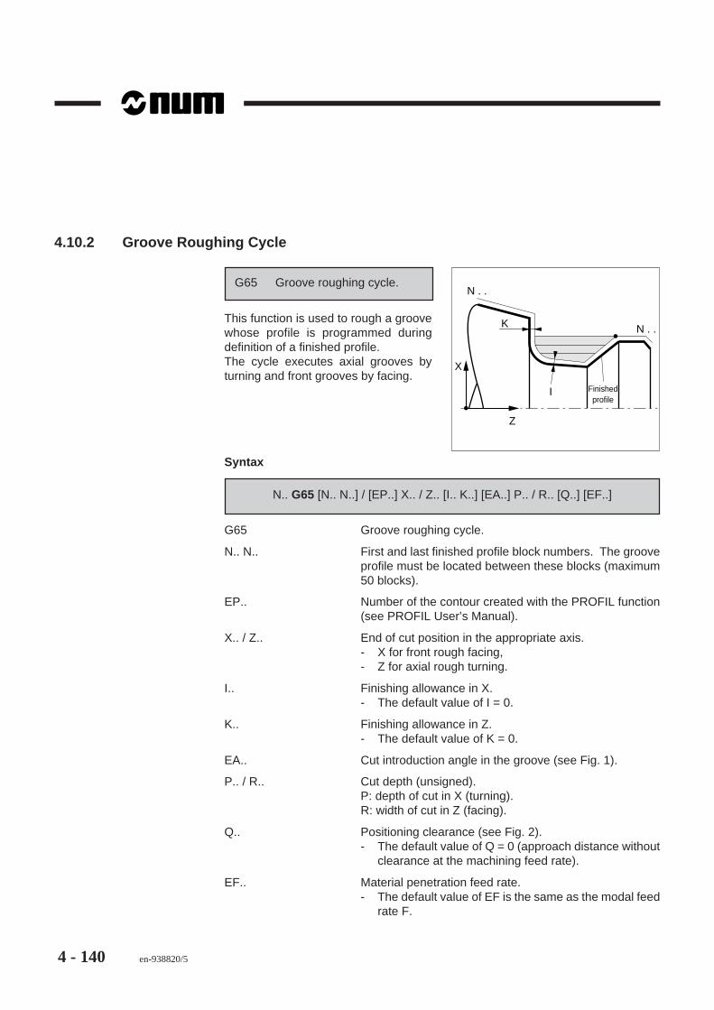
4 - 140 en-938820/5
4.10.2 Groove Roughing Cycle
Z
X
K
N . .
N . .
I Finishedprofile
G65 Groove roughing cycle.
This function is used to rough a groovewhose profile is programmed duringdefinition of a finished profile.The cycle executes axial grooves byturning and front grooves by facing.
Syntax
N.. G65 [N.. N..] / [EP..] X.. / Z.. [I.. K..] [EA..] P.. / R.. [Q..] [EF..]
G65 Groove roughing cycle.
N.. N.. First and last finished profile block numbers. The grooveprofile must be located between these blocks (maximum50 blocks).
EP.. Number of the contour created with the PROFIL function(see PROFIL User’s Manual).
X.. / Z.. End of cut position in the appropriate axis.- X for front rough facing,- Z for axial rough turning.
I.. Finishing allowance in X.- The default value of I = 0.
K.. Finishing allowance in Z.- The default value of K = 0.
EA.. Cut introduction angle in the groove (see Fig. 1).
P.. / R.. Cut depth (unsigned).P: depth of cut in X (turning).R: width of cut in Z (facing).
Q.. Positioning clearance (see Fig. 2).- The default value of Q = 0 (approach distance without
clearance at the machining feed rate).
EF.. Material penetration feed rate.- The default value of EF is the same as the modal feed
rate F.

ISO Programming
en-938820/5 4 - 141
4
Property of the Function
Function G65 is nonmodal.
Cancellation
Function G65 is cancelled at the end of the block.
Cycle Steps
Z
X
34
5
62
A
1
Step 1: Tool positioning (point A, cycle start).
Before the cycle start, the system takes into account the declared tool radius.
Step 2: Infeed at the introduction angle at the machining feed rate (to depth P forturning).
Step 3: Execution of the pass at the machining feed rate.
Step 4: Retraction at the machining feed rate along the groove profile.
Step 5: Rapid return to the perpendicular over the start point for the next pass.
Step 6: Positioning at the machining feed rate (if Q with a value not programmed).
The following passes are executed in the same way as steps 2 to 6.
After execution of the last pass, the tool retracts at rapid to the cycle start point.

4 - 142 en-938820/5
Notes
Both the finished profile definition blocks N.. to N.. must include both the coordinatesX and Z.
Tool positioning to the cycle start must be programmed in G40 (G41 or G42 radiusoffset cancelled).
The feed rate function and argument can be programmed in the cycle block, e.g.:N.. G65 N.. N.. I.. K.. P.. G95 F0.1.
At the end of the cycle, the system is left in G0 mode.
Notes on argument EA
R
Finished profile
A
EA
Figure 1- EA: cut introduction angle defines aline from the cycle start point (point A) tothe intersection with the finished profile.
After positioning to the start point, thesystem reads the declared tool radius(R) before executing the first pass.
Notes on argument Q
P
Q
Finished profile
Start point
Figure 2After the first pass, when argument Q isprogrammed with its value, the approachdistance before each new cut is carriedout in two steps:- At high speed up to value Q,- At the machining feed rate until the
start of the next pass.

ISO Programming
en-938820/5 4 - 143
4
Cycle used for dia. or face machining
Z
ZX
P
N . .
StartN . .
Dia. roughing
N70 ...N80 G65 N.. N.. Z.. I.. K.. EA.. P..N90 G52 X.. Z..N..
Face roughing
Z
X
X
R
N . .
N . .
Start
N70 ...N80 G65 N.. N.. X.. I.. K.. EA.. R..N90 G52 X.. Z..N..

4 - 144 en-938820/5
Example
Roughing an axial groove
1 to 45°
45°
10 15
40
1 to 45°ø
52
ø 3
0
R 5
ø 5
0
Machining paths
4
1
2
OP
X
Z
A
g
e d
c
b
af

ISO Programming
en-938820/5 4 - 145
4
%34N10 G00 G52 X.. Z.. Tool change positionN20 T03 D03 M06 (GROOVE ROUGHING TOOL R=0.4)N30 S900 M03 M40N40 X52 Z-15 Point A, tool at the start of the grooveN45 G92 S3000N50 G96 S100N60 G95 F0.2N70 G65 N100 N180 Z-40 I0.2 K0.1 EA-135 P2N80 G52 X..Z.. G97 S900N90 T05 D05 M06 (SLIDING TOOL R=0.8)N100 G42 X44 Z2 Point a, tool at the start of the profileN110 G96 S250N120 G01 X50 Z-1 F0.1 Point bN130 Z-15 Point cN140 X30 Z-25 Point dN150 Z-35 Point eN160 G02 X40 Z-40 R5 Point fN170 G01 X50 Point gN180 X60 Z-45 Point hN190 G00 G40 G52 X.. Z.. G97 S900 M05N.. ...

4 - 146 en-938820/5
4.10.3 Plunging Cycle
Z
X R
D1 D2
XZ
G66 Plunging cycle.
This function is used to rough a dia. orfrontal groove by consecutivepenetrations.
Syntax
N.. G66 D.. X.. Z.. [EA..] P../R.. [EP..] [EF..]
G66 Plunging cycle.
D.. Number of the second grooving tool correction (the firstcorrection must be programmed in one of the previousblocks, see Fig. 1).
X.. Z.. Groove machining end point (see Fig. 2).
EA.. Angle defining the slope across the groove bottom (seeFig. 2).- The default value of EA = 0 (no slope).
P../R.. Step between each penetration.P..: value along X (frontal groove).R..: value along Z (dia. groove).
EP.. Retraction (at 45 degrees) at the end of the pass (seeexample of special use of the cycle).
EF.. Dwell at the end of each penetration in seconds (FormatF022).- The default value of EF = 0.

ISO Programming
en-938820/5 4 - 147
4
Property of the Function
Function G66 is nonmodal.
Cancellation
Function G66 is cancelled at the end of the block.
Cycle Steps
Z
X
1
4
3
2
A
Step 1: Tool positioning above the material (point A, cycle start).
The first tool correction corresponding to the start side of the groove must beprogrammed in this block or in one of the previous blocks.
Step 2: Penetration at the machining feed rate (to the groove bottom point possiblymodified by angle EA).
Step 3: Retraction at the machining feed rate.
Step 4: Rapid movement by the value of the step for execution of the next penetration(taking into account the correction corresponding to the other side of the groove).
Execution of the following passes in the same way as steps 2 to 4 until reaching theend of the groove.
After execution of the last pass, retraction clear of the material.

4 - 148 en-938820/5
Notes
When the cycle is programmed, the system must be in state G40 (G41 or G42 toolradius offset cancelled).
The tool penetrations are uniformly distributed over the width of the groove. In certaincases, the system recomputes the programmed step.
The feed rate function and argument can be programmed in the cycle block, e.g.:N.. G66 D.. X.. Z.. R.. EA.. EF.. G95 F0.1.
At the end of the cycle, the system is left in G0 mode.
Declaration of the two tool corrections
Z
X
ZA
FIGURE 1
D15
D05
XZ
Turret origin
Example:
Correction D05: Groove start side alongZ (point A).
Correction D15: Groove end side alongZ (point XZ).
The difference in value between the twocorrections must be equal to the toolwidth.
Notes on arguments XZ and EA
Start side
XZ
EA
FIGURE 2The groove bottom slope is defined fromthe groove end point (point XZ) to theintersection with the groove start side.

ISO Programming
en-938820/5 4 - 149
4
Examples
Plunging an axial groove
OP
ZX
10°
3
ø 4
6
ø 6
0
A
XZ
30
50
N.. ...N210 G00 G52 X.. Z.. Tool change positionN220 T05 D05 M06 (GROOVING TOOL L=6)N230 G97 S900 M40 M03N240 X66 Z30 Point AN250 G96 S80N260 G95 F0.1N270 G66 D15 X46 Z50 EA10 R5 EF0.5 CycleN280 G52 X.. Z.. G97 S900 M05N..

4 - 150 en-938820/5
Special use of cycle G40 with EP
EP can be added to the cycle syntax to rough a diameter.
OP
Z
50
ø 8
0
EP3
ø 4
0
XZ
45° 5
P5
X
A
N.. ...N100 G00 G52 X.. Z.. Tool change position
$0 TURNING, DIAMETER 40N110 T01 D01 M06 (BIDIRECTIONAL TOOL R=08)N120 G97 S900 M40 M03N130 X70 Z5 Point A
N140 G96 S200N150 G95 F0.3N160 G66 X40 Z-50 P5 EP3 Cycle
N170 ...

ISO Programming
en-938820/5 4 - 151
4
4.10.4 Roughing Cycle with Groove
ER
XZ(EZ)
Finished profile
Programmed blank
Z
X
G63 Roughing cycle with groove.
This function is used for roughing a vo-lume of material located between thedefinition of a blank and a finished pro-file.
The cycle will machine a groove whoseprofile is compatible with the geometryand radius of the tool used. It can becarried out by facing or turning and forexternal or internal machining.
Syntax
N.. G63 [N.. N..] / [EP..] X.. Z.. EX.. / EZ.. P.. / R.. EA.. / EU.. / EW.. [EB..] [EC..][ER..] [Q..] [EQ..] [EF..]
G63 Roughing cycle with groove.
N.. N.. First and last block numbers defining the finished profile(maximum 95 blocks).
EP.. Number of the contour created with the PROFIL function(see PROFIL User’s Manual).
X.. Z.. (or U.. W..) Cycle start point.
EZ.. / EX.. Pass end point on the roughing axis:- EZ for rough turning along Z.- EX for rough facing along X.
Direction of roughing pass execution:- Z+ if EZ > Z Z- if EZ < Z- X+ if EX > X X- if EX > Z
P.. / R.. Pass depth:- P: value along X (rough turning)- R: value along Z (rough facing).

4 - 152 en-938820/5
EA../EU../EW.. Roughing pass start positions (see Figs. 1 and 2).
These arguments are programmed to define a start anglefor cut application and can be combined: EA EU, EA EWor EU EW.
EB.. Maximum groove penetration angle.
Angle used to take into account the groove profile geometryand the tool rake angle (α) (see Fig. 3).- By default, EB is parallel to the roughing axis.
EC.. Maximum cut exit angle.
Angle used to take into account the groove profile geometryand the tool angle of attack (K) (see Fig. 4).- By default, EC is perpendicular to the roughing axis.
ER.. Finishing allowance.
Value applied normal to the profile.- The default value of ER = 0.
Q.. Positioning clearance.
Approach distance at feed rate before contact with thematerial (for rapid to next cut depth).- The default value of Q = 0 (no clearance).
EQ.. Minimum chip value.- Below the programmed value, the pass is not executed.
EF.. Penetration feed rate in the material.- The default value of EF is the same as the modal feed
rate F.
Property of the Function
Function G63 is nonmodal.
Cancellation
Function G63 is cancelled at the end of the block.

ISO Programming
en-938820/5 4 - 153
4
Cycle Steps
Description of the first rough turning and grooving passes
Z
X
5
7
334 2
1
2
5 XZ
63
4 1
Rough turning pass
Step 1: Tool positioning to X Z.
Before the cycle begins, the system reads the declared tool radius .
Step 2: Rapid to first cut depth P (for turning).
Step 3: Execution of the first pass at the machining feed rate.
Step 4: Lift along the profile at the machining feed rate.
Step 5: Rapid return to the cycle start point.
The following passes are executed in the same way as steps 2 to 5.
After execution of the last roughing pass, the tool is retracted from the surface andpositioned in X.

4 - 154 en-938820/5
Grooving pass
Step 1: Rapid positioning in X.
Step 2: Rapid positioning in Z.
Step 3: Positioning in X at the machining feed rate.
Step 4: Cut application at the machining feed rate along the groove profile.
Step 5: Execution of the pass at the machining feed rate.
Step 6: Lift at the machining feed rate along the groove profile.
Step 7: Rapid return to the cycle start point.
The following passes are executed in the same way as steps 3 to 6.
After execution of the last pass, the tool is retracted from the surface and positionedin X.
Notes
The number of blocks from N.. to N.. must not exceed 95. Otherwise, the systemreturns error message 92.
When the cycle is programmed, the system must be in state G40 (G41 or G42 toolradius offset cancelled).
At the end of the cycle, the system is left in G0 mode.
The finished profile definition can be programmed before the cycle call, but in thiscase it is necessary to use the branch function G79 (see Sec. 4.11.3).
The cycle arguments defining positive angles are specified counterclockwise.
The feed rate function and argument can be programmed in the cycle block, e.g.:N.. G63 N.. N.. X.. Z.. EZ.. P.. EA.. EB.. ER.. Q.. EQ.. EF.. G95 F0.3

ISO Programming
en-938820/5 4 - 155
4
Notes on arguments EA, EU and EW
Figure 1
XZ
EA
Z
Pass setting
Intersection withfinished profileRoughing angle
- EA: Angle limiting the start of cutapplication between point XZ (cycle start)and intersection with the finished profile.(If there is no intersection, the last passis limited to the first point of the finishedprofile).
After positioning to point XZ, the systemreads the declared tool radius beforecarrying out the first cut application.
Figure 2
XZ
EUorEW
A
Z
Cut application
Roughing angle
- EU or EW: End point of the lastroughing pass. If argument EA is notprogrammed, the values declared withEU and/or EW and XZ (cycle start) areused to define the cut application startangle (A).
The angle is also used to differentiate between applying the cut at feedrate or rapidfor a groove or not, respectively:- Machining feed rate (in the material) if the angle between the cut application line
and the roughing axis is > 90 degrees.- Traversing rate (off the material) if the angle between the cut application line and
the roughing axis is < 90 degrees.

4 - 156 en-938820/5
Definition of EB and EC
Angle defined by EB Angle defined by EC
Figure 3
EB
α
Figure 4
K
EC
Machining of a groove limited by declaration of angles EB and EC.
When the groove profile and tool geometry are completely incompatible, the grooveis not executed.
EC
Partmachined
EB
Z
X
EBEC
Z
X
Part machined

ISO Programming
en-938820/5 4 - 157
4
Cycle differences between turning and facing
Z
X ER
P
EU
XZEZRough turning
N70 ...N80 G63 N.. N.. X.. Z.. EZ.. P.. EU.. EB.. ER..N90 G52 X.. Z..N..
Z
X ER
R
EX
XZEWRough facing
N70 ...N80 G63 N.. N.. X.. Z.. EX.. R.. EW.. EC.. ER..N90 G52 X.. Z..N..

4 - 158 en-938820/5
Examples
Rough and finish turning of an external profile
60
ø 3
6
ø 3
0
ø 5
0
R 12
ø 9
0
ø 2
6
2 H
ole
dia.
22
5
5 to 45°5 to 45°
70 12
90
40
Machining paths
5
ø 2
0
5OP Z
X
EZ XZ
40°k
l
ji h
gd
b af e c
50

ISO Programming
en-938820/5 4 - 159
4
%32N10 G00 G52 X.. Z.. Tool change positionN20 T01 D01 M06 (SLIDING TOOL R=0.8)N30 S900 M40 M04N40 X100 Z50 Tool position at the start of roughingN50 G92 S3500N60 G96 S200N70 G95 F0.25N80 G63 N110 N230 X100 Z50 EZ30 P2 EA-40 EB-145 ER0.4 Q2 EQ1 EF0.1N90 G52 X.. Z..N100 T03 D03 M06 (COPYING TOOL R=0.4)N110 G42 X20 Z95 Point a, tool at the start of finishingN120 G96 S250N130 G01 Z90 F0.4 Point bN140 X26 F0.1 Point cN150 X36 Z82 Point dN160 X30 Z75 Point eN170 Z70 Point fN180 X40 Point gN190 X50 Z65 Point hN200 Z60 Point iN210 G02 X50 Z40 R12 Point jN220 G01 X80 Point kN230 X100 Z30 Point lN240 G40 G52 X.. Z.. G97 S900 M05N250 M02

4 - 160 en-938820/5
Rough and finish facing of an external profile
ø 8
4
ø 7
0ø
50
ø 2
0
Dril
led
hole
dia
. 10
20
15
14
R6
R15
2 to 45°
R3
Undimensioned radius = tool R
������ ������� !!!!!!! """"""" ####### $$$$$$ %%%%%% &&&&&& '''''' (((((((((((((((((((((((((( )))))))))))))))))))))))))) ************************** ++++++++++++++++++++++++++ ,,,,,,,,,,,,,,,,,,,,,,,,,, -------------------------- .......................... ///////////////////////// 0000000000000000000000000 1111111111111111111111111 2222222222222222222222222 3333333333333333333333333 44444444444444444444444444 55555555555555555555555555 66666666666666666666666666 77777777777777777777777777 88888888888888888888888888 99999999999999999999999999 :::::::::::::::::::::::::: ;;;;;;;;;;;;;;;;;;;;;;;;;; <<<<<< ====== >>>>>>> ??????? @@@@@@@ AAAAAAA BBBBBBB CCCCCCC DDDDDDD EEEEEEMachining paths
OP
X
Z
g h5
3
f
e
d
cb
a XZ

ISO Programming
en-938820/5 4 - 161
4
%39N10 G00 G52 X.. Z.. Tool change positionN20 T07 D07 M06 (FACING TOOL =0.8)N30 S900 M40 M04N40 X100 Z10 Tool position at the start of roughingN50 G92 S3500N60 G96 S200N70 G95 F0.2N80 G63 N110 N190 X90 Z5 EX0 R2 EA-180 EB-150 EC-170 ER0.2 Q1 EF0.1N90 G52 X.. Z..N100 T09 D09 M06 (COPYING TOOL R=0.4)N110 G41 X90 Z-25 Point a, tool at the start of finishingN120 G96 S250N130 G01 X80 Z-20 F0.1 Point bN140 X70 Point cN150 G03 X50 Z-15 R6 Point dN160 G02 X40 Z-14 R3 Point eN170 G03 X20 Z0 R15 Point fN180 G01 X0 Point gN190 G00 Z5 Point hN200 G40 G52 X.. Z.. G97 S900 M05N210 ...N.. M02

4 - 162 en-938820/5
Execution of a profile by two outside rough turnings then finishing
Rough and finish turning an internal profile
�������������������� !!!!!!!!!!""""""""""##########$$$$$$$$$$%%%%%%%%%%&&&&&&&&&&&''''''''''((((((((((((((((((((((((((((()))))))))))))))))))))))))))))******************************++++++++++++++++++++++++++++++,,,,,,,,,,,,,,,,,,,,,,,,,,,,,,------------------------------..............................//////////////////////////////00000000000000000000000000000011111111111111111111111111111122222222222222222222222222222222222223333333333333333333333333333333333333444444444444444444444444444444444444455555555555555555555555555555555555556666666666666666666666666666666666666777777777777777777777777777777777777788888888888888888888888888888888888889999999999999999999999999999999999999::::::::::::::::::::::::::::::::::::;;;;;;;;;;;;;;;;;;;;;;;;;;;;;;;;;;;;<<<<<<<<<<<<<<<<<<<<<<<<<=========================>>>>>>>>>>>>>>>>>>>>>>>>????????????????????????@@@@@@@@@@@@@@@@@@@@@@@@AAAAAAAAAAAAAAAAAAAAAAAABBBBBBBBBBBBBBBBBBBBBBBBBCCCCCCCCCCCCCCCCCCCCCCCCCDDDDDDDDDDDDDDDDDDDDDDDDDEEEEEEEEEEEEEEEEEEEEEEEEEFFFGGGHHHHIIIIJJJJKKKKLLLMMMNNNOOOø
120
2030
4010
80
5
2065
ø 8
0
ø 7
0ø
60
ø 3
0
ø 4
0
Dril
led
hole
dia
20
5 to 45°
5 to 45°
5 to 45°
7520 25
85
R5
R15
External machining paths
3 o
OP Z
X
n
m lk j i h
g fe d
c
ba
XZEU
EU (roughing 1)
(roughing 2)
XZ (roughing 1)EZ (1)
EZ (2)

ISO Programming
en-938820/5 4 - 163
4
Internal machining paths
j'
OP
2
Z
X
i' h'g'
EZ
f' e' d'c' b'
a'
k'XZ
%163N10 G0 G52 X.. Z.. Tool change position$0 EXTERNAL ROUGHING 1N20 T01 D01 M06 (TOOL R0.8)N30 S900 M40 M04N40 X126 Z5 Tool position at the start of roughing 1N50 G92 S4000N60 G96 S260N70 G95 F0.3N80 G63 N150 N300 X126 Z5 P3 EZ-85 EU16 EB-170 EC-93 ER0.2 EQ1 Q1 EF0.2N90 G0 G52 X.. Z.. G97 S900$0 EXTERNAL ROUGHING 2N100 T03 D03 M06 (TOOL R0.8)N110 X80 Z5 Tool position at the start of roughing 2N120 G63 N150 N300 X72 Z5 P1.5 EZ-65 EU70 EB-125 EC-93 ER0.2 Q1 EF0.15N130 G0 G52 X.. Z.. G97 S900$0 EXTERNAL FINISHINGN140 T11 D11 M06 (COPYING TOOL R0.8)N150 G42 G0 X16 Z5 Point aN160 G96 S300N170 G01 Z0 F0.08 Point bN180 X60 Point cN190 X70 Z-5 Point dN200 Z-20 Point eN210 X60 Z-25 Point fN220 Z-30 EB-2 Point g

4 - 164 en-938820/5
N230 X70 EB2 Point hN240 Z-40 EB2 Point iN250 G02 X70 Z-60 R15 EB2 Point jN260 G01 Z-65 Point kN270 X80 Z-75 Point lN280 Z-80 Point mN290 X116 Point nN300 X126 Z-85 Point oN310 G0 G40 G52 X.. Z.. G97 S900 M05$0 INTERNAL ROUGHINGN320 T05 D05 M06 (BORING TOOL R0.8)N330 S900 M40 M03N340 X10 Z10 Tool position at the start of roughingN350 G92 S3000N360 G96 S70N370 G95 F0.1N380 G63 N420 N520 X16 Z5 EU50 EZ-92 P2 EB110 EC70 ER0.2 Q1 EQ0.5 EF0.1N390 G0 Z5 Tool retractionN400 G0 G52 X.. Z..$0 INTERNAL FINISHINGN410 T07 D07 M06 (BORING TOOL R0.4)N420 G41 X50 Z5 Point a’N430 G96 S90N440 G01 X30 Z-5 F0.07 Point b’N450 Z-20 Point c’N460 X40 Z-25 Point d’N470 Z-45 EB2 Point e’N480 G02 X40 Z-55 I40 K-50 EB2 Point f’N490 G01 Z-75 Point g’N500 X30 Z-80 Point h’N510 Z-85 Point i’N520 X16 Z-92 Point j’N530 G0 Z5 Point k’, Tool retractionN540 G40 G52 X.. Z.. G97 S900 M05N550 M02

ISO Programming
en-938820/5 4 - 165
4
4.11 Breaks in Sequence
4.11.1 Unconditional Branch to a Subroutine or Sequence of Blocks with Return
Main programme
%10N . .N . .N . . G77. . . N . .N . . %
N . .N . .N . .
Subroutine
G77 Unconditional branch to asubroutine or sequence ofblocks with return.
Subroutines included in the main pro-gramme or separate from it are called byaddresses H.. and/or N.. N.. associatedwith the function.
Syntax
N.. G77 [H..] [N.. N../N..] [P..] [S..]
G77 Unconditional branch to a subroutine or sequence ofblocks with return (maximum 8 nesting levels).
H.. Number of a subroutine external to the main programme.
N.. N.. Number of the first and last block called (If both N.. have thesame number or if only one block is programmed, only oneblock is called).
P.. Number of the contour created by the PROFIL function(see PROFIL Function User’s Manual).
S.. Number of times the subroutine or sequence of blocks isto be repeated (default = 1, maximum 99 repetitions).
Property of the Function
Function G77 is nonmodal.
Cancellation
Function G77 is cancelled at the end of the block.

4 - 166 en-938820/5
Notes
Subroutines called by address H end with «X OFF» and do not include an M02 block(end of programme).
A subroutine called by addresses N.. N.. can be located between M02 and «X OFF».
If argument S is programmed in a block containing other instructions, it mustimmediately follow the subroutine branch.
If the subroutine branch is defined by two sequence numbers in reverse order (e.g.G77 N200 N10), the system executes the programme in the normal sequence fromN10 to N200 and no error is displayed.
Context
The calling programme context can be saved at the beginning of the calledprogramme. It can then be restored at the end of execution of the called programme.The programmed status access symbols are used for save and restore (see Sec. 6.7).
Inhibiting display of subroutines being executed
Display on the programme page (PROG) of a subroutine and its internal subroutinesduring execution can be inhibited.
Placing the character «:» after the subroutine number inhibits display. Only thesubroutine call block is displayed.
Example:
Main programme %10 calling subroutine %110: itself containing an internal subroutine%210.
Only block N50 of programme %10 is displayed during execution of subroutines%110 and %210.
%10 %110: %210N10 N10 N10N.. N.. N..N50 G77 H110 N80 G77 H210 N..N.. N.. N..

ISO Programming
en-938820/5 4 - 167
4
Examples
Branches to external subroutines from the main programme
%10N10N . .N . . G77 H11N . .N . .N . .N . . M02
%11N10N . .N . . N . .N . .
Once
Branch to subroutine %11 from mainprogramme %10.
%20N10N . .N . . G77 H21 S3N . .N . .N . .N . . M02
%21N10N . .N . . N . .N . .
3 times
Branch to subroutine %21 from mainprogramme %20 three times.
%30N10N . .N . . G77 H31 N50 N90 S2N . .N . .N . . M02
%31N . .N50N . . N . .N . .N90N . .
Tw
ice
Branch to blocks N50 to N90 of subroutine%31 from main programme %30 twice.

4 - 168 en-938820/5
Branches to sequences in the programme
%40N10N . .N . .N70N . .N . . G77 N70 N70N . .N . . M02
Branch to block N70 located upstream inprogramme %40.
The block can be called by:N.. G77 N70 N70orN.. G77 N70
%50N10N . .N . .N80N . .N140N150 G77 N80 N140 S3N . .N . . M02
3 times
Branch to blocks N80-N140 locatedupstream in the programme %50 threetimes.
%60N10N . .N . . G77 N500 N550 S4N . .N400 M02N500 N . .N550
4 times
Branch to blocks N500-N550 locateddownstream in programme %60,between M02 and X OFF, four times.

ISO Programming
en-938820/5 4 - 169
4
Subroutine nesting
Subroutine %5263 and the sequence of blocks N20 to N100 of main programme%123 are executed three times (S3).
Main programme Subroutine 1 Subroutine 2
% 123 % 252 % 5263N10 N10 N600N20 N20 N610N.. N.. N..N.. N.. N..N50 G77 H252 N80 G77 H5263 S3 N650N60 N90 N660N.. N.. N..N.. N.. N..N100 N160 N700 G77 N610 N650N110 N710N.. N..N.. N..N180 G77 N20 N100 S3 N920 G77 H123 N210 N260N190 N930N.. N..N210 N1290N..N260N..N300 G77 N500 N550N310N..N..N390 M02N..N500N..N..N550

4 - 170 en-938820/5
Cutting grooves by calling two subroutines
515
40
ø 4
0
ø 3
6 R1
ø 2
0
ø 3
0
3
Machining paths
2
D7Z
OP Z
X
d'
c'
a'
b'
c a
b
d
1
D05Z

ISO Programming
en-938820/5 4 - 171
4
Main programme
%30N10 G0 G52 X0 Z0$0 EXTERNAL MACHININGN..N..N110 G0 G40 G52 X.. Z.. G97 S900$0 VEE-GROOVEN120 T05 D05 M06 (TOOL WIDTH 5)N130 X32 Z-15 Point a, approachN140 G96 S80N150 G77 H35 Call to subroutine %35N160 G77 N110 Call to sequence N110$0 GROOVE WITH RADIUSN170 T07 D07 M06 (TOOL RADIUS 1)N180 G0 G42 X44 Z-40 Point a’, approachN190 G96 S50N200 G77 H40 Call to subroutine %40N210 G77 N110 M05 Call to sequence N110N220 M02
Subroutine 1
%35N10 G91 G01 X-6 G95 F0.08 Point b, incremental dimensionsN20 X6 Outfeed to point aN30 G0 Z-3 Point cN40 G01 X-1 F0.3 Point dN50 X-5 Z3 F0.05 Point eN60 X6 F0.08 Point aN70 G90
Subroutine 2
%40N10 G91 G01 X-4 G95 F0.06 Point b’, incremental dimensionsN20 Z-5 F0.08 Point c’N30 X4 F0.3 Point d’N40 G90

4 - 172 en-938820/5
4.11.2 Subroutine Branch by M Function
Current programme
%50N . .N . .N . .N . . M55N . .N . .
%255N . .N . .N . .
Subroutine
M.. Subroutine branch by Mfunction.
The M.. function branches to a subroutinewhose number is assigned by the ma-chine manufacturer (see machineparameter P35).
Syntax
N.. M..
M.. Subroutine branch by M function.
Property of the Function
Function M.. programmed is modal.
Notes
A subroutine called by an M function cannot itself call another subroutine by an Mfunction. However, it can be nested with another type of call (by G function orautomatic control function), but in no case may two calls of the same type be nested.
A block including a subroutine call by M function may also include a positioningcommand.
Example: N.. M200 G00 X100
In this case, the block is processed in the following order:- M200 sent to the PLC,- Movement X100 executed,- Call to the subroutine defined in P35.

ISO Programming
en-938820/5 4 - 173
4
Return to current programme
After execution of the subroutine, none of the data programmed earlier are restored.
The following data must be reprogrammed if necessary:- modal preparatory G functions,- modal technological S functions and miscellaneous M functions,- correction D even if the tool was not changed,- programme variables L.
Context
The calling programme context can be saved at the beginning of the calledprogramme. It can then be restored at the end of execution of the called programme.The programmed status access symbols are used for save and restore (seeSec. 6.7).
Specific Feature of a Call to a Subroutine Number Between %11001 to %11999
When the subroutine number declared in P35 is between %11001 and %11999, thesubroutine is called before execution of the block containing the M function and blockconcatenation is forced. It should noted that within the subroutine, execution of thefunctions is enabled by G998 and/or G997 as in subroutine calls by Gxxx function.
Example:
Execution of spindle indexing during axis movement in a block containing theprogramming: N.. X.. Y.. Z.. M19.
REMARK For information on most of the functions used in the example below,refer to Sections 4.14.17, 6.7 and 7.3 of this manual as well as to thesupplementary programming manual.

4 - 174 en-938820/5
%11019 (SPINDLE INDEXING DURING MOVEMENT)VAR [br_pos] = [.BM62] *2+ [.BM65] *2+ [.BM64] - [.BM63] /2&3+93524
[M998] = [.BM999] - [.BM997] + 998[tix(9)] [i]
ENDVM997 (forced block sequencing)FOR [i] = 1 TO 9 DO [tix(i)] = [.IBX(i)] BCLR [.IBX(i)] (stop movement)ENDFG997 (exit M19)G999FOR [i] = 1 TO 9 DO IF [tix(i)] = 1 THEN
BSET [.IBX(i)] (enable movement) ENDIENDFG997 (start movement)(wait until spindle is in position)WHILE E [br_pos] = 0 DO G4 F.1ENDWM[M998]
Example
General case: call by function M55 of subroutine %255.
Current programme Subroutine %255
%50 %255N10 ... N10 ...N.. N..N80 M55 N..N.. N120N..N950 M02

ISO Programming
en-938820/5 4 - 175
4
4.11.3 Branch to a Sequence without Return
Current programme
%100N . .N . .N . . G79 N350N . . N . .N350N . .N . .
G79 Conditional or unconditionalbranch to a sequencewithout return.
A conditional or unconditional branch ismade to sequence number N.. associatedwith the function..
Syntax
N.. G79 [L../E.. > = < Number] N..
G79 Conditional or unconditional branch to a sequence (anupstream or downstream branch is allowed).
L.. or E.. Variable L or parameter E tested in the condition (seeSecs. 6.1 and 6.2).
> = < Comparison symbols for the condition (up to two symbolscan be used).
Number Numerical expression of the condition.
N.. Mandatory argument defining the sequence number towhich the jump is to be made.
Property of the Function
Function G79 is nonmodal.
Cancellation
Function G79 is cancelled at the end of the block.
Notes
If the jump is conditional, the condition must be located between G79 and N..

4 - 176 en-938820/5
Examples
Unconditional jump
%25N10 ...N..N50 G79 N220 Jump to sequence N220N60N..N190N..N220N..N250 G79 N60 Jump to sequence N60N..
Conditional branch
Counting the number of machining operations performed and branching when thespecified number is reached.
%75N10 L5 = 20 Variable L5 set to 20N20 G52 Z..N30 T01 D01 (TOOL)N40 S800 M40 M03N50 G00 X.. Y.. Z.. N60 G01 Z..N70N..N.. Programming for one machiningN.. operationN..N..N..N140N150 L5 = L5 -1 Count each operation downN160 G79 L5 = 0 N180 Condition: If L5=0, branch to block N180N170 G79 N50 Branch to N50N180 G52 Z.. M05N190 M02

ISO Programming
en-938820/5 4 - 177
4
Roughing cycle with unconditional branch
5
fe
d
b
a
c
4
30 OP Z
X
R5
ø 6
0
ø 4
0
Roughing cycle start
%82N10 G00 G52 X.. Z..N20 T01 D01 M06 (BIDIRECTIONAL TOOL)N30 S900 M40 M04N40 X70 Z4 Roughing start pointN50 G92 S3000N60 G96 S200N70 G79 N140 Branch to block N140N80 G00 X30 Z4 Point aN90 G01 X40 Z-1 Point bN100 Z-30 Point cN110 X50 Point dN120 G03 X60 Z-35 R5 Point eN130 G01 X70 Point fN140 G64 N80 N130 I0 K0 P2 G95 F0.2N150 X70 Z-35N160 Z4N170 X30N180 G80 G52 X-50 Z-100 G97 S900N190 ...

4 - 178 en-938820/5
4.11.4 Subroutine Call by Automatic Control Function
Part programme
%81N . .N . . N . . N . .N . .N . .N . .
Machine processor
%9999N . . N . . N . .N . .
Subroutine
During execution of a part programme,the automatic control function causes abranch to subroutine %999.
Condition for the branch to subroutine %9999
Part programme being executed in mode:- automatic (AUTO),- single step (SINGLE),- dry run (DRYRUN).
A subroutine called by the automatic control function cannot itself call anothersubroutine by the automatic control function. However, it can be nested with anothertype of call (by M function or G function), but in no case may two calls of the same typebe nested.
Start of subroutine %9999
If a part programme is already being executed, the branch to subroutine %9999 isonly made at the end of an interruptible block or the end of execution of anuninterruptible block.
Definition: An uninterruptible block is a block containing a G function causing a branchto a subroutine (G31, G45, G81, etc.) or a block for which certain parameters mustbe known in order to execute the next block (sequencing of three blocks in PGPmode).
If no part programme is being executed when subroutine %9999 is called, the CYCLEfield goes out at the end of execution of the subroutine (the part programme is notexecuted).
Functions G01 and G40 are set at the start of the subroutine.
During execution of the subroutine %9999
The PLC ignores a new call or maintaining of the call to subroutine %999 duringexecution of this subroutine.

ISO Programming
en-938820/5 4 - 179
4
End of the subroutine %9999
At the end of execution of the subroutine, the system does not make a handshake withthe m/c processor. It is the subroutine's responsibility to report on its execution byfunction M or external parameter E.
The subroutine should end with X OFF unless a return to the current programme isnot desired. In this case, function M02 (end of programme) is programmed at the endof the subroutine.
Return to current programme
After execution of the subroutine, none of the data programmed earlier is restored.
The following data must be reprogrammed if necessary:- modal preparatory G functions,- modal technological S functions and miscellaneous M functions,- correction D even if the tool was not changed,- programme variables L.
Context
The calling programme context can be saved at the beginning of the calledprogramme. It can then be restored at the end of execution of the called programme.The programmed status access symbols are used for save and restore (see Sec. 6.7).
Structure of subroutine %9999
When several functions can be processed by a subroutine, the PLC must specify thefunction called. This may be done by external parameter E40000 (see Sec. 6.2).
Example:
Method 1:
Each function is the subject of a specific subroutine (%a, %b, %c, etc.). In this case,subroutine %9999 is a single block used to re-direct control.
%9999G77 H E40000 M..N..Parameter E40000 contains the number of the subroutine called (a, b, c, etc.) and theM function is used as a handshake (CRM).
This method has the drawback of creating an additional subroutine nesting level.

4 - 180 en-938820/5
Method 2:
All the functions are written in subroutine %9999. The first block is a jump to asequence number contained in parameter E40000 (i.e. Na.., Nb.., Nc..).
%9999G79 N E40000 M.. Wait for start by CRM and the branch to
the sequenceNa Processing of function 1N..N..G79 Nz Jump to the last sequenceNb Processing of function 2N..N..G79 Nz Jump to the last sequenceNc Processing of function 3N..N..Nz End of subroutine
Subroutine Call by Automatic Control Function with Axis Multigroups
See Sec. 4.17 (special programming for axis multigroups).

ISO Programming
en-938820/5 4 - 181
4
4.11.5 Block Interrupt
Programme
%300N . .N . .N . . N200 X . . G10 @7 < 50.3 N250N . .N . .N250N . .
G10 Block interrupt.
G10 blocks are designed to be interruptedby a hardware input or by satisfying aposition threshold for a particular axis
After the interrupt, a branch may bearranged to a designated block. If nointerrupt is detected, the next block isexecuted.
Syntax
N.. [G40] [G04 F..] [G00/G01/G02/G03] X.. Z.. G10 [:n] [+X.. or F..] [@n < >Value] N.. [+ Number] [EF..]
G40 Tool radius offset cancel.
G04 F.. Interruptible dwell.
G00/G01/G02/G03 Interruptible interpolations.
X.. Z.. Interruptible axes.
G10 Block interrupt function.
:n Numerical argument (number of interrupts from 1 to 99)significant only for hardware interrupts (on-the-fly dimensionmeasurement). The block is not interrupted (forcing an endof block) until the nth hardware interrupt.
+X.. or F.. Arguments defining a movement or dwell to be made afterthe interrupt(s).
X..: A further movement to be made after the interrupt(s)before deciding whether to branch (possible on all the axesof the system, both measured and servoed).
F..: Dwell in seconds during which the block may beinterrupted.

4 - 182 en-938820/5
@n < > Value Argument defining a condition for comparison with athreshold.
@n: Physical address of the axis concerned by the test(axis address n is between 0 and 31).
<>: Mandatory comparison symbol.
Value: Comparison threshold in the same programme unitas the other axes of the group (mm or inches).
N.. + Number Branch to block N.. after the interrupt, possibly followed bya further number to reach unnumbered blocks.
EF.. Maximum feed rate after an interrupt (seeSec. 4.11.5.1).
Property of the Function
Function G10 is nonmodal.
Cancellation
Function G10 is cancelled at the end of the block.
Notes
All the arguments for function G10 are optional.
Analysis of the interrupt
When function G10 is programmed, the end point programmed in the block may bemodified by setting of the limit switch bit (ARBUT) or by a CNC interrupt generatedby an IT input (part gauging function). Either of these inputs stops movement andreplaces the dimensions of the required position by the dimensions of the currentposition.
When the programming movement is finished, the system jumps to the programmedsequenced or by default to the next sequence.
On-the-fly dimension measurement (hardware interrupt)
The hardware interrupt is generated on an interrupt input.
If movement is stopped by a gauging interrupt, the automatic control functionprocesses this IT and informs the CNC. When interrupt IT is generated, thedimensions of the axes in the group are stored in external parameters E7x001 (axisposition reference where x = physical address of the axis, see Sec. 6.2). The interruptis taken into account by function G10 of the part programme that can then cause abranch.

ISO Programming
en-938820/5 4 - 183
4
The new values can be detected by dynamic operators and stored in an indexedaddressing table.
REMARK With axis multigroup programming (see Sec. 4.17), when an interrupton one group is set at the same time as an interrupt on another group(groups 1 to 8), the interrupt on the group with the lowest number haspriority.
Examples
G10 block with a jump to an unnumbered block
Jump to the third block after N150 if a hardware interrupt is set.
N.. ...N80 G01 G41 X.. Z.. F200
Jump to N150
+ 3 blocks
N90 G40 X.. G10 N150 +3N100N..N150N..N..N..N..
Interruptible block including comparison with a threshold and jump to a block once thecondition is satisfied
Condition: Jump to block N240 when the measurement on axis 7 is less than 50.3.
N.. ...N..
Jump to N240N200 X.. Z.. G10 @7 < 50.3 N240N..N..N240N..

4 - 184 en-938820/5
Interruptible block including comparison with a threshold and jump to a block if thecondition is satisfied
N..N200 G00 G40 X50
Condition satisfied
Condition not satisfied
Jump to N220 or N250N210 G01 X100 Z120 G10 : 2 + X60 N250N220N230N240N250N..If, after the interrupt, the end point is beyond the original programmed target:- the jump condition is not satisfied and the programme continues with the next
block,- no updates are made to the E7x001 positions.
Diagram:
60 mmITIT
N210 N220X100Z120
ITIT 60 mm
Jump to N250
Continue with N220

ISO Programming
en-938820/5 4 - 185
4
4.11.5.1 Special Use of Sequence Interrupt
Block Sequencing without Stopping Movement
In state M999 (see Sec. 4.14.9), the analysis of the following blocks is suspended untilthe interrupt is detected, whether this interrupt is from the PLC (programmed withA.15B) or a hardware interrupt or a conditional interrupt determined by comparing anaxis measurement to a threshold.
When the interrupt is detected, if the current interpolated position (to which is addedthe +X value programmed after G10) is beyond the programmed end point, it shouldbe noted that:- analysis of the following blocks is resumed immediately,- in case of possible processing by parametric programming, the current block is
considered ended, thereby authorising read or write of external parameters E (seeSec. 6.2) without effectively stopping current movements (this allows calculationof a positioning point according to the interrupt point and taking into account thegeometric transformations made downstream of the interpolator),
- as soon as the next block is ready, the feed rate at the end of the current block isupdated according to whether the path has changed or not.
REMARK In state M999, if the block was not interrupted, a subroutine call by thePLC is accepted at the end of execution of the block.
Feed Rate Limiting After an Interrupt
Before the interrupt, the speed of movement in block G10 is the modal feed rate Fprogrammed before G10. After the interrupt, the feed rate at the end of the currentblock may be different if argument EF and its value (less than F) are programmed inthat block or an earlier block.
Example
N..N.. G01 X30 G94 F300N..N.. G00 X..N100 G01 X0 F150 G10 +X2 EF100 Feed rate 100 mm/min after the
interruptN..

4 - 186 en-938820/5
Example
The example below is defined for a system using inclined axis programming.
For the specific data used in the example, refer to the additional information given inthis manual for:- Inclined axes- External parameters E...- Symbolic variables [...].
%398N..N..(Compute the offset between the machine dimension and programme dimension in theprogramme reference system)[K] = CE69001 [DECX] = UE70000 * [K] - [.IRX(1)]N150 G01 X0 F200 G10 +X2 EF100(Go to 5 mm from the interrupt point)N160 [COTE] = [K] * UE70001 - [DECX] - 5 X[COTE] F100N..In the figure:- point a: point measured on the interrupt- point b: current position interpolated at the time of the interrupt.
N150
Penetration on X2 mm
N160
5 mm
Feed rate
ba

ISO Programming
en-938820/5 4 - 187
4
4.11.6 Temporary Suspension of Next Block Preparation
G79 +/- Temporary suspension of next block preparation in asequence with movements.
Programming this function in a block with movements temporarily suspends preparationof the next block. A lead or lag (expressed in millimetres or seconds) at the beginningof the current block or at the end of execution of the current block is programmed onthe restart of block processing.
Syntax
N.. [G00/G01/G02/G03] X.. Y.. Z.. G79 +/- X.. / F..
G00/G01/G02/G03 Linear or circular interpolation.
X.. Y.. Z.. End point.
G79 Temporary suspension of next block preparation insequences with movement.
+/- +: Lag with respect to the start of the current block.-: Lead with respect to the end of execution of thecurrent block
X.. / F.. X..: Lag or lead in millimetresF..: Lag or lead in seconds.
Properties of the function
Function G79 is nonmodal.
Cancellation
Function G79 is cancelled at the end of the block.

4 - 188 en-938820/5
Notes
Restart of processing after programming of the function
As soon as analysis of the next block is restarted, it should be noted that:- in case of possible processing by parametric programming, the current block is
considered ended, thereby authorising read or write of external parameters E (seeSec. 6.2) without effectively stopping movements,
- as soon as the following block is ready, the feed rate at the end of the current blockis updated,
- this allows write of external parameters E and discrete outputs or read and test ofthese parameters without stopping movements.
Example
Example with timeout at the start of the current block
N..N110 G00 X0 Z5N120 G01 X100 G79+F4 Movement along X with 40-secondN130 G79 E10000=1 N300 timeout before analysis of block N130N140 Y20N..N300 G01 X200N..
Example with anticipation at the end of the current block
N..N110 G00 X50 Z5 Movement along Y with anticipation ofN120 G01 Z100 G79-X10 10 mm before analysis of block N130N130 ...

ISO Programming
en-938820/5 4 - 189
4
4.11.7 Emergency Retract
Part programme
%30N10 G75 N300N . .N . . N . . N . . M02N300N . .N . .
Emergency retractactivation area
PLC
Emergency retract subroutine
G75 Declaration of an emergencyretract subroutine.
The emergency retraction subroutine isactivated by a request from the PLC.
Activation stops the current programmeand causes a branch to address N.. ofthe last emergency retract subroutinedeclared.
Syntax
N.. G75 N..
G75 Declaration of an emergency retract subroutine.
N.. Mandatory argument associated with the function andgiving the address of the emergency retract subroutinestart sequence number.
Properties of the Function
Function G75 is nonmodal. Argument N.. associated with the function is modal.
Cancellation
Declaration of a subroutine G75 N.. is cancelled by:- cancellation function G75 N0,- function G75 N.. with a different subroutine number,- end of programme function M02,- a reset.
Notes
Condition for activation of the emergency retract subroutine
Part programme being executed in one of the following modes:- automatic (AUTO),- single step (SINGLE),- manual data input (MDI),- dry run (DRYRUN).

4 - 190 en-938820/5
An emergency retract subroutine can be activated:- after reading the block in which it is programmed,- as long as the programme or subroutine in which it is declared is not completed,- as long as a new emergency retract subroutine has not been declared,- as long as emergency retract has not been cancelled by G75 N0.
If emergency retract is activated but no emergency retract subroutine has beendeclared in the part programme, this instruction has the same effect as pressing the«ARUS» (cycle stop) key.
Activation of an emergency retraction is sent by the PLC function with the emergencyretraction request «C_DGURG».
In automatic mode, the emergency retraction programme remains active untilencountering a function M00 or M02.
Emergency retraction on PLC axis groups
For information, see Sec. 4.18 (programming specific to PLC axes).

ISO Programming
en-938820/5 4 - 191
4
Examples
Declaration of emergency retract subroutines from a main programme
%30N10N..N40 G75 N1000
If emergency retract is activated in this area of the programme, branch to N2000
If emergency retract is activated in this area of the programme, branch to N1000
Emergency retraction subroutine available for N40 to N180
Emergency retraction subroutine available for N190 to N290
Part programme resumption sequences
N..N..N180
N190 G75 N2000N..N..N290N300 M02
N1000N..N..N1050 M02
N2000N..N..N..N2080 M00
N2090N..N..N2120

4 - 192 en-938820/5
Declaration of emergency retract subroutines from a programme including subroutinebranches
If an emergency retract subroutine is activated during execution of subroutine %4called by N200 of %2, branch to N300 of %2.
If an emergency retract subroutine is activated during execution of subroutine %4called by N40 of %3, branch to N200 of %1.
Déclaration dedégagementd'urgence
Programme dedégagement d'urgence
Déclaration dedégagementd'urgence
Programme dedégagementd'urgence
%1 %2N10 G75 N200 N10 G75 N300N.. N..N.. N200 G77 H4N.. N..
N.. G79 N390N100 G77 H2 N300N.. N..N150 G77 H3 N.. M02N.. N390N180 M02 N..N200N..N..N.. %3N.. M02 N10
N..N40 G77 H4N..
%4N10N..N..

ISO Programming
en-938820/5 4 - 193
4
4.11.8 Branch to Automatic Homing Subroutine
Homing can be carried automatically on each of the machine axes by runningsubroutine %9990.
Conditions for running subroutine %9990
Subroutine %9990 is run by pressing the cycle start button:- if the system is in homing mode,- if no other programme is being executed.
During execution of subroutine %9990
As soon as subroutine %9990 or one of its subroutines starts, the machine axes canbe moved without affecting homing.
End of execution of subroutine %9990
At the end of execution of subroutine %9990 (by programming of M02), theprogramme that was active when %9990 was called is resumed.
Automatic homing with multiple axis groups
See Sec. 4.17 (programming specific to multiple axis groups).

4 - 194 en-938820/5
4.11.9 Subroutine Branch on a Reset
On a reset, the NC groups can execute subroutine %11000.
Conditions for running subroutine %11000
Subroutine %11000 is run:- if bit 3 of machine parameter P7 word 2 is a 1,- if this subroutine is present in the memory.
Start of execution of subroutine %11000
Subroutine %11000 begins approximately 100 microseconds after the reset pulse(S RAZ or E_RAZ) goes high. It should be noted that this pulse remains high until thesubroutine ends.
Contents of subroutine %11000
A subroutine %11000 must not include any executable functions such as:- Movements on the axes- Dwells (G04 F..)- Miscellaneous functions (M..), etc.
Only the following operations are allowed in subroutine %11000:- read and write of external parameters E and programme variables L (see
Chapter 6). It should be noted that at the end of execution of the subroutines,variables L0 to L19 are reset but the others preserve their values,
- declaration of dynamic operators and enabling of interaxis calibration (seeDynamic Operators Manual),
- declaration and initialisation of symbolic variables [...]. It should be noted that theymust be saved by the SAVE function to be available for use after execution of thesubroutine (see Supplementary Programming Manual).
Subroutine branches on a reset in multiple axis groups
See Sec. 4.17 (programming specific to multiple axis groups).

ISO Programming
en-938820/5 4 - 195
4
4.11.10 Restrictions Related to Drip Feed Mode
NC drip feed mode
Magnetic tape unit + tape
Machining
Computer + disk driveDrip feed mode allows a programme tobe checked or to be executed as theprogramme is read from a reader ortransmitted from a host (DNC1).
Drip feed mode is used for execution oflarge programmes which cannot bestored in the NC (for the procedure, seeoperator’s manual).
Notes
Use of drip feed mode causes allocation of a buffer space of up to 32,000 characters.
When the space available is less than this value but more than 1 KB, the system takesall the remaining space.
If the space available is less than 1 KB, drip feed mode is refused and error message36 is reported.
Restrictions related to drip feed mode
It is impossible to use functions referring to block numbers in the programme:- jump to a sequence (G79 N..),- block interrupt (G10 N..),- branch to sequences of the main programme (G77 N.. N..),- activation of an emergency retract subroutine (G75 N..).
Branches to subroutines stored in the memory are allowed in drip feed mode (G77 H..or G77 H.. N.. N..).

4 - 196 en-938820/5
4.11.11 Call to Subroutine Return Block
G77 -i Call to subroutine return block.
This function allows a subroutine to call and execute the instructions of the returnblock of the calling subroutine.
Syntax
N.. G77 - i
G77 Call to subroutine return block.
-i Immediate value (or variable) giving the nesting level of theprogramme containing the block called with respect to thenesting level in which G77 -i is programmed (the returnblock called in this way is automatically postincremented).
Properties of the Function
Function G77 -i is nonmodal.
Cancellation
Function G77 -i is cancelled at the end of the block.
Notes
If the block called is in the «displayable» programme, it is displayed on theprogramme page (PROG) even if the subroutine that called it is not displayable.
It should be noted that:- if the nesting level requested is not accessible, the system returns error message
26- the blocks called by G77 -i must not include branches or other calls (G79, G77,
etc.) or the system returns error message 26.

ISO Programming
en-938820/5 4 - 197
4
Examples
General Example
%1 %10 %100N.. N.. N..
N.. N.. N..
N3 G77 H10 N30 G77 -1 N300 ...
N4 ... N40 G77 H100 N400 G77 -2
N5 ... N50 ... N500 ...
N6 ... N60 G77 -1 N600 ...
N7 ... N70 ... N700 ...
N8 ... ... ...
Specific Example
REMARK For information on the functions used in the example below, refer toSections 4.14.17, 6.7 and 7.7 of this manual as well as to thesupplementary programming manual.
%1 %10100N... ... (processing of the calling block)N... WHILE [.NOG80] = 100 DO G999 G77 -1G100 ... ... (processing of the blocks located between G100... ... and G80 G997 (execution)... ENDWG80...

4 - 198 en-938820/5
4.11.12 ISO Programme or Block Creation/Deletion
G76+/- ISO programme or block creation/deletion.
4.11.12.1 General
Programming of function G76+/- provides the following capabilities:- Programme creation- Programme deletion- Block insertion in a programme- Block deletion from a programme.
This function is especially useful for creating part programmes automatically (e.g.after teach-in by gauging of dimensions).
This function can only be used to create and delete programmes and blocks locatedin part programme area zero.
REMARK Before execution of a function G76+ (creation, insertion), the systemmakes sure no other programme editor or graphic display is active. Ifso, programme execution is suspended as long as these conditionsremain present.
With G76, the programme number can be indexed (e.g. H123.2). This is acceptedproviding no other programme in any of the programme areas has the same number.
If there is not enough memory space for programme creation or block insertion, thesystem returns error message 266.
If the block including function G76 has a format error, the system returns errormessage 1.
Properties of the Function
Function G76 is nonmodal and is cancelled at the end of the block.
4.11.12.2 Creating a Programme
The syntax below is used to create a programme in area zero.
Syntax
N.. G76+ H..
G76+ Programme creation function.
H.. Number of the programme to be created.

ISO Programming
en-938820/5 4 - 199
4
Notes
In programme creation mode, the programme number must be the last word in theblock.
Example
Programme creation in RAM programme area (area zero).
%350...N110N120 G76+ H123.1N130...
PROGRAMME AREA IN RAM
%233 ...%45 ...%345 ...%123.1 ...
4.11.12.3 Deleting a Programme
The syntax below is used to delete a programme located in area zero.
Syntax
N.. G76- H..
G76- Programme deletion function.
H.. Number of the programme to be deleted.
Notes
The programme number must be the last word in the block.
Several cases can occur, depending on the area where the programme is located:- If a programme in area zero has the number specified in the function, this
programme is deleted- If a programme in an area other than area zero has the number specified in the
function, deletion is refused and the system returns error message 266- If no programme in any area has the number specified with the function, the
command is accepted (but no programme is deleted).

4 - 200 en-938820/5
Example
Programme deletion in RAM programme area (area zero).
%1050...N190N200 G76- H10.1N210...
PROGRAMME AREA IN RAM
%459 ...%423 ...%336 ...%10.1 ...
4.11.12.4 Inserting a Block
The syntax below is used to insert a block in an existing programme.
Syntax
N.. G76+ [H..] N..[+number] ISO block
G76+ Function defining block insertion.
H.. Specifies the programme number where the block is to beinserted (optional: default H..: the ISO block is inserted inthe programme including function G76).
N.. +number N..: Block number (mandatory). The insertion is madeafter this block unless “+number” is specified (note: the firstblock of programme %.. is block N0).+number: (optional) defines the number of lines (after theblock number specified) where the insertion is to be made.
ISO block Block to be inserted consisting of ISO functions (see listunder Notes).

ISO Programming
en-938820/5 4 - 201
4
Notes
The following ISO functions are accepted:- N.. (block number)- G.. (preparatory functions; several G functions are accepted in the block)- X.. Y.. Z.. U.. V.. W.. A.. B.. C.. (axes and dimensions)- I.. J.. K.. (circle centre coordinates)- P.. Q.. R.. (material vector for 3D radius correction)- /.. (polynomial coefficients)- L=.. to L9=.. (programme variables).
The values associated with the above functions are immediate integer or fractionalvalues, programme variables (L..), symbolic variables [sym] or parameters E. Whenthey are parameters E, the values are specified in the internal system unit (these dataare edited in the programme as immediate values, signed if negative, and in theinternal unit defined for linear or rotary axes).
The block to be inserted must not have more than 120 characters or the systemreturns error message 1.
If there is not enough memory space for block insertion, the system returns errormessage 266.
If the block to be inserted does not exist, the system returns error message 25.
Example
Block insertion in programme %336 located in the RAM programme area (area zero).
%36N.. ...N290 ...N300 G76+ H336 N100 +2 N125 G01 X50 Z20N310 ......
N100 +2
Block insertion
%336N.. ...N100 ...N110 ...N120 ...
N130 ......

4 - 202 en-938820/5
4.11.12.5 Deleting a Block
Syntax
N.. G76- [H..] N..[+number]
G76- Block deletion function.
H.. Specifies the programme number from which the block isto be deleted (optional: default H..: the ISO block is deletedfrom the programme including function G76).
N.. +number N..: Block number (mandatory). It is this block that isdeleted unless +number is programmed (note: the firstblock of programme %.. is block N0).+number: (optional) specifies the line to be deleted (afterthe block number specified).
Notes
If the block to be deleted does not exist, the system returns error message 25.
Example
Deletion of a block in programme %567 located in the RAM programme area (areazero).
%222N.. ...N90 ...N100 G76- H567 N200 +4N110 ......
N200 +4
Block deletion
%567N.. ...N.. ...N200 ...N210 ...N220 ...N230 ...N240 ......

06-97 en-938820/5
NUM1020/1040/1060T
PROGRAMMINGMANUALVOLUME 2
0101938820/5

2 en-938820/5
Despite the care taken in the preparation of this document, NUM cannot guarantee the accuracy of the information it contains and cannot be held
responsible for any errors therein, nor for any damage which might result from the use or application of the document.
The physical, technical and functional characteristics of the hardware and software products and the services described in this document are subject
to modification and cannot under any circumstances be regarded as contractual.
The programming examples described in this manual are intended for guidance only. They must be specially adapted before they can be used in
programs with an industrial application, according to the automated system used and the safety levels required.
© Copyright NUM 1997.
All rights reserved. No part of this manual may be copied or reproduced in any form or by any means whatsoever, including photographic or magnetic
processes. The transcription on an electronic machine of all or part of the contents is forbidden.
© Copyright NUM 1997 software NUM 1000 family.
This software is the property of NUM. Each memorized copy of this software sold confers upon the purchaser a non-exclusive licence strictly limited
to the use of the said copy. No copy or other form of duplication of this product is authorized.

ISO Programming
en-938820/5 4 - 203
4
4.12 Movement Origin Selection
4.12.1 Programming of Movements in Absolute Coordinates Referenced to theMeasurement Origin
OM
Pointprogrammé
Z
X
G52
G52 Programming of movementsin absolute coordinatesreferenced to themeasurement origin.
Movements programmed with thisfunction are referenced to themeasurement origin (OM).
All the axes are programmable withreference to the measurement origin.
Syntax
N.. [G40] [G90] [G00/G01] G52 X.. Z.. C.. [F..]
G40 Radius offset cancel.
G90 Programming in absolute dimensions.
G00/G01 Linear interpolations at high or programmed speed.
G52 Programming of movements in absolute coordinatesreferenced to the measurement origin.
X.. Z.. C.. End point referenced to the measurement origin.
F.. Feed rate.
Property of the Function
Function G52 is nonmodal.
Cancellation
Function G52 is cancelled at the end of the block.

4 - 204 en-938820/5
Notes
Programming function G52 in a block suspends the following data:- tool data,- DAT1,- DAT2,- programme origin offset (G59),- angular offset (ED..),- scaling factor (G74).
Function G52 must:- precede programming of the axes in the block,- be programmed with the system in G40 mode (radius offset cancel) or the system
returns error message 27,- be programmed in absolute coordinates (G90).
Examples
Programming G52 on the X and Z axes with reference to the measurement zeropoint before a tool change
Measurement zero point
Turret zero point
Z
X
%10N10 G00 G52 X0 Z0N20 T03 D03 M06N..
Programming of G52 on axes Z, X, C:- -50 mm from the measurement zero point on the Z axis- -100 mm from the measurement zero point on the X axis- 180 degrees from the measurement zero point on the C axis.
N.. ...N220 G00 G52 Z-50N230 G52 X-100 C180N..

ISO Programming
en-938820/5 4 - 205
4
Programming of the carrier/carried axes
A parallel carrier/carried axis pair can be programmed in G00 with reference to themeasurement origin. In all other cases, programming in G00 is prohibited.
Example:
DAT1 and DAT2 do not apply to the values programmed with the Z and W axes.
N..N.. G00 G52 Z.. W..N..

4 - 206 en-938820/5
4.12.2 Datum Shift DAT1 and DAT2 Cancel/Enable
CANCEL / ENABLE
Scale E1000/1000
DAT1X - 100Z - 200C + 0
DAT2+ 0+ 20+ 0
G53 DAT1 and DAT2 cancel.
G54 DAT1 and DAT2 enable. .
These functions are used to enable orcancel DAT1 and DAT2 shifts enteredon the SHIFT page.
Syntax
N.. G53/G54
G53 DAT1 and DAT2 cancel.
G54 DAT1 and DAT2 enable.
Properties of the Functions
Functions G53 and G54 are modal.
Function G54 is the default function.
Cancellation
Functions G53 and G54 cancel one another.
Notes
The tool offsets are not affected by function G53.

ISO Programming
en-938820/5 4 - 207
4
4.12.3 Programme Origin Preset
X
Z
X
Z
G92 . .
OP1
OP0
Currentpoint
G92 Programme origin preset.
This function, associated with one ormore axes and their values, defines thecurrent point with reference to a newprogramme origin.
DAT1 values are redefined for theprogrammed axes.
Syntax
N.. G92 X.. Z..
G92 Programme origin preset.
X.. Z.. Position with respect to the new programme origin.
Calculation for programme origin preset on an axis:
New DAT1 = Previous DAT1 + Previous current point/OP - Value programmed withG92
or
New DAT1 = Current point/OM - Value programmed with G92 - Tool length (in theaxis) - DAT2
This operation is not performed until completion of the block before that containingfunction G92.
! CAUTION
The new offsets remain active at the end of the programme.

4 - 208 en-938820/5
Programme origin preset function G92:- applies to all the axes, both carried and independent,- is rejected if the last movement was programmed with respect to the origin, error
message 2,- is ignored in test (TEST) and sequence number search (SEARCH) modes,- suspends analysis of blocks until execution of the previous block is completed,- cannot be programmed with radius offset; the system must be in state G40,- cannot be programmed in a PGP (Profile Geometry Programming) sequence.
Example
Value entered for Z DAT1 = -300
Value entered for Z DAT 2 = 20
Tool length L (correction D9) = 80
Programme origin preset G92 Z60
N..N150 G00 D9 G40 X0 Z40N160 G92 Z60 PresetN170 G00 Z..N..
Analysis of block N150 yields:- current point/OM Z = -160
Application of the first equation
New Z DAT1 = -300 + 40 - 60 = -320
Application of the second equation
New Z DAT1 = -160 - 60 - 80 - 20 = -320

ISO Programming
en-938820/5 4 - 209
4
4.12.4 Programme Origin Offset
G59
OP Z
X
OffsetOP1
G59 Programme origin offset.
This function, associated with one ormore arguments, axes and values, off-sets the programme origin (OP).
An origin offset can be assigned to eachsystem axis.
No movement is caused by the functionand its arguments.
Syntax
N..[G90/G91]G59 X.. Z.. U.. W.. C..[I.. K.. ED..]
G90/G91 Programming in absolute or incremental dimensions.
G59 Programme origin offset.
X.. Z.. U.. W.. C.. The axes programmed are the arguments associated withthe function. They must immediately follow the functionand at least one axis must be programmed.
I.. K..ED.. - I.. K..: Arguments defining the centre of rotation of anangular offset programmed with ED in the plane withrespect to the initial programme origin (see Fig. 1).- ED..: Angular offset.
Properties of the Function
Function G59 is nonmodal. The arguments associated with the function are modal.
Cancellation
A programmed offset G59.. is cancelled by:- programming G59 with axis arguments assigned zero values in absolute dimen-
sions (G90),- the end of programme function (M02),- a reset.

4 - 210 en-938820/5
Notes
For simplification and understanding of the programme, it is recommended to be instate G90 (absolute programming) before programming an origin offset.
Function G59 programmed in absolute dimensions (G90):
The origin offset G59 ... is referenced to DAT1 + DAT2. A new origin offset G59 ...replaces a previous one.
Function G59 programmed in incremental dimensions (G91):
The first movement programmed after G59 ... is translated by the value of theprogramme origin offset. The absolute position is offset by the sum of all theincremental G59 ... functions programmed earlier.
The functions below, when included in a programme, must be programmed in thefollowing order:- G59 ... Programme origin offset,- ED.. Angular offset,- G51 ... Mirror function,- Scaling factor.
Notes on arguments I, K
OP
G59
Z
ED..
Axis of rotation
Figure 1
Z..
X
X..
I..
K..
Machining programmed with referenceto a programme origin (OP) can betranslated and oriented according to theangle programmed with ED (see Sec.4.12.5).
N.. ...N.. G59 X.. Z.. I.. K.. ED..N.. ED..N..An offset on the X and Z axes is notmandatory for programming I and K.

ISO Programming
en-938820/5 4 - 211
4
Examples
Origin offsets on the Z axis in absolute programming (G90)
Z
X
OP0 Z
X
DAT1, DAT2Measurement
origin
30
60
OP2 OP1
%60N10N..N50N..N90N..N120 G90 G59 Z-30 Offset 1N.. G77 N50 N90 MachiningN..N230 G59 Z-60 Offset 2N.. G77 N50 N90 MachiningN..N350 G59 X0 Offset cancelledN..

4 - 212 en-938820/5
Origin offsets on the Z axis in incremental programming (G91)
Z
X
OP0 Z
X
DAT1, DAT2Measurement
origin
30
30
OP2 OP1
%70N10N..N50N..N90N..N120 G91 G59 Z-30 Offset 1N.. G77 N50 N90 MachiningN..N230 G59 Z-30 Offset 2N.. G77 N50 N90 MachiningN..N350 G91 G59 Z-60 ou G90 G59 X0 Cancellation possible with G90 or G91N..

ISO Programming
en-938820/5 4 - 213
4
Machining allowance by origin offset
Bore roughing, finishing. Machining allowance: X = 0.3, Z = 0.2
6666666666666666777777777777777788888888888888889999999999999999:::::::::::::::;;;;;;;;;;;;;;;<<<<<<<<<<<<<<<===============>>>>>>>>>>>>>>>???????????????????@@@@@@@@@@@@@@@@@@@AAAAAAAAAAAAAAAAAAABBBBBBBBBBBBBBBBBBBCCCCCCCCCCCCCCCCCCCCDDDDDDDDDDDDDDDDDDDDEEEEEEEEEEEEEEEEEEEEFFFFFFFFFFFFFFFFFFFFGGGGGGGGGGGGGGGGGGGGHHHHHHHIIIIIIIJJJJJJJKKKKKKKKLLLLLLLLMMMMMMMMNNNNNNNNOOOOOOOPPPPPPP25
1 to 45°
Hol
e di
a. 2
0
ø 2
460
Machining paths
OP Z
X d 0.22 0.3
a
e
2
666666666666666677777777777777778888888888888888999999999999999:::::::::::::::;;;;;;;;;;;;;;;<<<<<<<<<<<<<<<===============>>>>>>>>>>>>>>>???????????????????@@@@@@@@@@@@@@@@@@@AAAAAAAAAAAAAAAAAAABBBBBBBBBBBBBBBBBBBCCCCCCCCCCCCCCCCCCCCDDDDDDDDDDDDDDDDDDDDEEEEEEEEEEEEEEEEEEEEFFFFFFFFFFFFFFFFFFFFGGGGGGGGGGGGGGGGGGGGHHHHHHIIIIIIJJJJJJJKKKKKKLLLLLLMMMMMMNNNNNNOOOOOOPPPPPPbc
N.. ...N80 G00 G52 X.. Z.. G97 S500N90 T07 D07 M06 (ROUGHING BORING TOOL)N100 G95 F0.2N110 S900 M04 M40N120 G59 X-0.3 Z0.2 Origin offsetsN130 G00 G41 X30 Z62 Point aN140 G96 S80N150 G01 X24 Z59 Point bN160 Z25 Point cN170 X16 Point dN180 G00 Z62 Point eN190 G59 X0 Z0 Offsets cancelledeN200 G40 G77 N80 N80N210 T09 D09 M06 (FINISHING BORING TOOL)N220 G77 N130 N180 FinishingN..

4 - 214 en-938820/5
Use of origin offset on a lathe with two turrets
On lathes equipped with two turrets (front and rear), the tool dimensions of thesecondary turret can be identified with respect to the reference of the master turretby programming an origin offset.
Front turret-master
OP
Z
G59
X +
300G59 Z-50
D1 Z . .
D1
X .
.X
D5 Z . .
D5
X .
.
Rear turret
% 88$0 MACHINING WITH FRONT MAIN TURRETN10 G00 G52 X0 Z0N20 T01 D01 M06 (EXTERNAL TOOL)N..N..N340 G00 G52 X0 Z0$0 MACHINING WITH REAR TURRETN350 T05 D05 M06 (INTERNAL TOOL)N360 G90 G59 X300 Z-50N..N500 G59 X0 Z0N..

ISO Programming
en-938820/5 4 - 215
4
4.12.5 Angular Offset
ED . .
OP
ED.. Programmed angular offset.
Function ED associated with a valuedefines an angular rotation with respectto the programme origin.
The angular offset applies to the axes ofthe plane programmed in the blocksfollowing the function.
Syntax
N.. [G90/G91] ED..
G90/G91 Programming in absolute or incremental dimensions.
ED.. Value of the angular offset in degrees and thousandths ofa degree (format ED+034).
Property of the Function
Function ED.. is modal.
Cancellation
Angular offset ED.. is cancelled by:- reprogramming function ED with a zero value (ED0) in absolute dimensions
(G90),- the end of programme function (M02),- a reset.
Notes
Angular offset ED applies to:- all the elementary cycles (G81 ...),- radius offset (G41, G42),- PGP (Profile Geometry Programming) unless ED.. is programmed between two
blocks that are not completely defined,- carried or independent secondary axes (U, W).

4 - 216 en-938820/5
4.13 Spline Curve Interpolation
4.13.1 General
Spline curve interpolation is a mathematical curve fitting method. Spline curves arecontinuous curves connecting a series of points.
Spline curve interpolation insures continuity of the tangent and a constant accelerationin each of the points specified on the programmed paths.
Machining of a spline curve is programmed by:- defining the points on the curve,- specifying a curve execution order.
A spline curve can be deleted by programming.
4.13.2 Programming
G48 Spline curve definition.
A spline curve definition includes several instructions:- the definition function,- the curve number,- the blocks defining the points on the curve.
G06 Spline curve execution command.
A spline curve execution command is given by a block containing the executioncommand followed by the number of the curve to be executed.
G49 Spline curve deletion.
The system allows memory space to be freed by deleting curves that have alreadybeen executed.
A curve is deleted by programming the delete function followed by the number of thecurve to be deleted.

ISO Programming
en-938820/5 4 - 217
4
4.13.2.1 Spline Curve Interpolation
G48 Spline curve definition.
Syntax
N.. G48 NC.. H../N.. N..
G48 Spline curve definition function.
NC.. Argument defining the curve number.
H.. Number of the subroutine in which are defined thepoints on the curve (optional).
N.. N.. Numbers of the first and last block defining the points onthe curve.
Property of the Function
Function G48 is nonmodal.
Cancellation
Function G48 is cancelled at the end of the block.
Notes
On a turning machine whose X (or U) axis is programmed on diameter (seeParameter Manual: machine parameter P4), programming a spline curve results inthe following requirements:- the block containing the spline curve definition function (G48 ...) must be preceded
by external parameter E11005=0 (forcing programming on radius, see Sec. 6.2)- the points in the curve definition (N.. to N..) must be programmed on radius- when the curve is completed (G06 NC..), programming on radius can be cancelled
by E11005=1 (forcing programming on diameter).
Blocks defining the points of a curve
The first and last block defining a curve must include the origin and end tangents. Ifthe tangents are not known, these blocks must be empty.
All the definition blocks other than the first and last (tangent to the start and end points)must include points on the curve (no empty lines). Otherwise, the curve plotted wouldbe different from the one desired.

4 - 218 en-938820/5
The first point definition block must include all the axes concerned by spline curveinterpolation. If an axis is not programmed in this block, it is not included in splinecurve interpolation even if it is programmed in the following blocks. In this case, it isinterpolated linearly. It is necessary to programme the same position in this first blockas in the block preceding function G06.
Blocks defining the tangents and points of a spline curve.
Z
X
Start0
Z-3
X4
The projections along the X and Z axesof the tangent to the curve origin haveX4, Z-3 as relative values.
N.. X4 Z-3 Tangent to the origin
X.. Z..X.. Z..X.. Z.. Points on the curveX.. Z..X.. Z..N.. X.. Z.. Tangent to the end pointN..
The number of points defining a spline curve is limited to 255. If this value isexceeded, the system returns error message 196.
The points in a spline curve must be defined by ISO programming.
A spline curve must be defined by at least three points. If it is defined by less thanthree points, the system returns error message 604.
Function G48 must be programmed in state G40, i.e. without radius offset (G41 orG42). Otherwise, the system returns error message 140.
The following functions can be programmed on the curve definition blocks:- miscellaneous M functions,- technological F, S or other functions.
Special characters such as $, (), etc. should not be programmed in the curve definitionblocks.
It is not recommended to programme modulo 360 degree axes with spline curves(problem of sign and no movement).
A closed curve is not processed automatically unless the tangents to the start and endpoints are identical.

ISO Programming
en-938820/5 4 - 219
4
Saving spline curve data
The curve coefficients are stored in tables of the programme stack. When theprogramme stack is full, the system returns error message 195. In this case, the stacksize can be extended (see Chapter 7).
The following data are stored for each spline curve defined:- 1 table with 5 entries,- 3 tables with P x Q entries, where:
P: number of axes concernedQ: number of points in the profile
- 1 table with P entries.

4 - 220 en-938820/5
4.13.2.2 Spline Curve Execution Command
G06 Spline curve execution command.
Syntax
N.. G06 NC..
G06 Function forcing execution of a spline curve.
NC.. Number of the curve to be executed.
Property of the Function
Function G06 is nonmodal.
Cancellation
Function G06 is cancelled at the end of the block.
Notes
The following functions cannot be programmed in the block containing function G06NC..:- F: feed rate,- S: spindle speed,- T: tool change.
The curve execution command G06 forces the polynomial interpolation function (seeSupplementary Programming Manual).
Error Numbers and Messages for Spline Curve
The errors are in error category 600 (See Appendix D).

ISO Programming
en-938820/5 4 - 221
4
4.13.2.3 Programming Examples
Programming of a spline curve defined in the ZX plane with a call to definition blocksin the main programme.
%70N10 ...N..N..$0 FINISHING OF THE SPLINE PROFILEN180 G0 G52 X0 Z0 G97 S900 M05N190 G79 N220 Jump to block N220
N200 X0 Z-1 Tangent to the origin of the curve
G01 X35 Z-10 F0.15X37 Z-13X40 Z-25 Points in the curve (c, d, e, f, g)
X35 Z-50X40 Z-80N210 No tangent to the end point
N220 T01 D01 M06 (FINISHING TOOL)N230 S900 M03 M40E11005=0 Forcing programming on radiusN240 G48 NC1 N200 N210 Spline curve definition
N250 G0 G42 X10 Z5 Point a
N260 G96 S300N270 G95 F0.3N280 G02 X15 Z0 I15 K5 Point b
N290 G03 X35 Z-10 R30 Point c
N300 G06 NC1 Curve execution order
N310 G01 G40 X45 Point h
E11005=1 Forcing programming on diameterN320 G77 N180 N180N330 M02

4 - 222 en-938820/5
Representation of machining
OP Z
X
h
Tangentto the origin
g fe d
c
ba

ISO Programming
en-938820/5 4 - 223
4
Programming of a spline curve defined in the XZ plane with call to the definition blocksin a subroutine.
%150N10N..N200 G0 G52 X0 Z0 G97 S500 M05N210 T03 D03 M06 (FINISHING TOOL)N220 S2000 M40 M04E11005=0 Forcing of programming with reference
to the radiusN230 G48 NC1 H151 N10 N130 Curve definition
E11005=1 Programming with reference to thediameter
N240 G0 X30 Z5 Point a
N250 G92 S3000N260 G96 S250E11005=0 Forcing of programming with reference
to the radiusN270 G01 G42 X11 G95 F0.3 Point a’
N280 G06 NC1 Execution order
E11005=1 Programming with reference to thediameter
N290 G01 Z-105 Point l
N300 G40 X30 Point m
N310 G77 N200 N200N320 M02
%151N10 X0 Z-1 Tangent to the origin
N20 X11 Z5 F0.1 Curve start
N30 X6 Z-10N40 X5 Z-20N50 X12 Z-40N60 X17 Z-60N70 X12 Z-80 Points on the curve (a to k)
N80 X8 Z-84N90 X5 Z-88N100 X9 Z-91N110 X11 Z-93N120 X12 Z-95N130 X0 Z-1 Tangent to the end point

4 - 224 en-938820/5
Representation of machining
OP Z
aTangent
to the origina'
bcd
e
fg
h
ij
kl
m
X

ISO Programming
en-938820/5 4 - 225
4
4.13.2.4 Freeing Memory by Deleting a Spline Curve
G49 Spline curve deletion.
This function is used to free the memory space occupied by curves already executed.
Syntax
N.. G49 NC..
G49 Spline curve deletion.
NC.. Number of the curve to be deleted.
Property of the Function
Function G49 is nonmodal.
Cancellation
Function G49 is cancelled at the end of the block.
Notes
Function G49 must be programmed in state G40, i.e. without radius offset (G41 orG42). Otherwise the system returns error message 140.
Example
Definition and execution of a spline curve followed by deletion of the curve
%300N10 ...N.. G79 N200N110 X.. Z..N.. Points in curve 1N..N150 X.. Z..N..N200 G48 NC1 N110 N150 Curve 1 definitionN300 G06 NC1 Curve 1 execution
N..N..N450 G49 NC1 Curve 1 deletion
N..

4 - 226 en-938820/5
4.14 Coordinates Systems with C Axis
4.14.1 Programming in Polar Coordinates
X
C +
C -
XZC
G20 Programming in polarcoordinates (X, Z, C).
This function is used to programme thelinear axes X and Z and control a rotaryaxis C, modulo 360 degrees.
X/Z programming is the same asprogramming a system without a C axis.
N.. [G40] G20 [G00/G01][X.. Z.. C..][F..]
G40 Radius offset cancel.
G20 Programming on axes X, Z and C (angular value C.. withreference to the origin).
G00/G01 Interpolations permitted.
X.. Z.. C.. End point.
F.. Feed rate.
Properties of the Function
Function G20 is modal and is the default function.
Cancellation
Function G20 is cancelled by functions G21 and G22.

ISO Programming
en-938820/5 4 - 227
4
Notes
Programming of function ER is excluded in G20.
Notes on declaration of the C axis
Control of the C axis requires the use of:- a servo-drive- a position encoder- a special drive arrangement.
Example
N.. ...N1050 G40 G21 (or G22) ... Machining in cartesian or cylindrical
coordinatesN..N1220 G40 G20 G01 X.. Z.. Return to initial stateN..

4 - 228 en-938820/5
4.14.2 Definition of the Start X for Interpolation on the C Axis
X . .
C -
C +
X
G98 Definition of the start X forinterpolation on the C axis.
When the system is in G20 mode, thisfunction is used to compute the feed rateon the C axis in mm/min.
Syntax
N.. G98 X..
G98 Definition of the start X for interpolation on the C axis.
X.. Start X.
Property of the Function
Function G98 is nonmodal.
Cancellation
Function G98 is cancelled at the end of the block.
Notes
Programming G98 X.. does not cause any movement.
When function G98 X.. is not programmed, the last value declared with the X axis isused for the computation.
When the C and X axes are interpolated simultaneously, the system performs itsfeedrate calculation from the mean radius.

ISO Programming
en-938820/5 4 - 229
4
4.14.3 Programming in Cartesian Coordinates
C
XG21 Programming in cartesian
coordinates (X, Y, Z).
The system performs cartesian/polarcoordinate conversion (X-Y converted toX-C).
Interpolation of the X and C axes allowsmilling in the plane perpendicular to thespindle axis.
The tool is driven by an auxiliary spindle.
Syntax
N.. [G40] G21 [G00/G01] [G41/G42] [X.. Y.. Z..] [G94 F..]
G40 Radius offset cancel.
G21 Programming in cartesian coordinates.
G00/G01 Interpolations.
G41/G42 Radius offset to the left or right of the profile.
X.. Y.. Z.. End point.
G94 F.. Feed rate in mm/min.
Property of the Function
Function G21 is modal.
Cancellation
Function G21 is cancelled by function G20.
Notes
Programming
Function G21 cannot be programmed during a canned cycle. The use of a cyclecauses generation of error message 76.
G21 is used for programming the X, Y and Z addresses by linear interpolation (theZ address is incompatible with circular interpolation G02 and G03).

4 - 230 en-938820/5
Programming a point in G21:
X
XaYa
(Y)N.. ...N.. G21 Xa YaN..
During transition from G20 to G21:- the system must be in G40 mode (radius offset cancel),- if the last block in G20 includes an X demand, it must have a positive value,- the system must not be programmed in PGP (Profile Geometry Programming).
During cancellation of G21 by G20, the system must be in G40 mode (radius offsetcancel).
Failure to comply with the transition and cancellation conditions causes generationof error message 75.
Offsets
Programming of offsets is allowed:- G59 X.. Y.. or G59 C..: Programmed origin offset,- ED..: Programmed angular offset,- G51..: Mirroring.

ISO Programming
en-938820/5 4 - 231
4
X+
(Y+)
Spindlezero
30°
An angular offset programmed on the Caxis causes a rotation of the X and Ycoordinates, e.g.:
N.. ...N.. G59 C30N..
Tool corrections
No change of tool corrections are authorised in G21. The corrections must beprogrammed and modified in G20.
Feed rate limiting
When the tool is moving toward the centre of the part, the constant feed rate alongthe path is achieved by increasing the angular feed rate on the C axis and decreasingthe linear feed rate on the X axis.
The system may therefore have to decrease the tangential machining feed rate so asnot to exceed the maximum rotation speed on the C axis.
The system automatically limits the minimum rotation speed on the C axis.When the minimum speed is reached, the system returns error message 34.
The minimum radius R is calculated by the following equation:344000
R = –––––––VCmax
Where:- R is the distance between the cutter centre and the C axis centre in µm,- VCmax is the maximum speed on the C axis expressed in degrees/minute (see
machine parameter P30).

4 - 232 en-938820/5
Example
Execution of two flats
Z
820 A/F
OP
ø 30
OPX (CO)
N..N200 G00 G40 G52 X.. Z.. M05N210 T12 D12 M06 (CUTTER D=10)N220 G97 S1000 M.. $0 AUXILIARY SPINDLE ROTATIONN230 X50 Z2 Tool approach along XZN240 G94 F..N250 G21 G01 G42 X10 Y11.18N260 G00 Z-8 Pass setting on ZN270 G01 Y-11.18 Execution of flat 1N280 G00 X-10N290 G01 Y11.18 Execution of flat 2N300 G00 Z3N310 G40 G20 X100N320 ...

ISO Programming
en-938820/5 4 - 233
4
Execution of a shape
Z
3
5
10
5OPToo
l R
R 5
X (CO)
ø 65
N..N200 G00 G40 G52 X.. Z.. M05N210 T8 D8 M06 (CUTTER D=8)N220 G97 S1200 M.. $0 AUXILIARY SPINDLE ROTATIONN230 X70 Z2 Tool approach along XZN240 G94 F..N250 G92 R1N260 G21 G00 G41 X-5 Y35N270 G00 Z-3 Pass setting on ZN280 G01 Y5N290 X5N300 G03 X5 Y15 R5N310 G01 Y35N320 G00 G40 G20 X200N330 G52 X0 Z0N340 ...

4 - 234 en-938820/5
4.14.4 Programming in Cylindrical Coordinates
C
Z
G22 Programming in cylindricalcoordinates (X, Y, Z).
The system performs cylindrical/polarcoordinate conversion (Y-Z converted toZ-C).
Interpolation of the C axis allows millingon the developed cylinder with radius X.
The tool is driven by an auxiliary spindle.
Syntax
N.. [G40] G22 [G00/G01] [G41/G42] [X.. Y.. Z..] [G94 F..]
G40 Radius offset cancel.
G22 Programming in cylindrical/polar coordinates.
G00/G01 Interpolations.
G41/G42 Radius offset to the left or right of the profile.
X.. Y.. Z.. End point.
G94 F.. Feed rate in mm/min.
Property of the Function
Function G22 is modal.
Cancellation
Function G22 is cancelled by function G20.
Notes
Programming
G22 is used for programming addresses:- X, Y and Z by interpolation G01- Y, Z, J and K by interpolations G02 and G03.

ISO Programming
en-938820/5 4 - 235
4
When the C axis rotates in the positive direction, the Y axis also increases positively.
Position Y0 coincides with position C0 of the C axis.
With G22, canned cycles are not authorised. The use of a canned cycle causesgeneration of error message 76.
Programming of a point in G22:
CY
b
o
b
a aZZ
N
N.. ...N.. Xa ZaN..N.. G22 Yb ZbN..
During transition from G20 to G22:- the system must be in G40 mode (radius offset cancel),- if the last block in G20 included a movement along X, it must be programmed
with a positive value,- the system must not be programmed in PGP (Profile Geometry Programming).
During cancellation of G22 by G20:- the system must be in G40 mode (radius offset cancel),- the system must not be programmed in PGP.
Failure to comply with the transition and cancellation conditions causes generationof error message 75.
Offsets
No offsets are allowed in G22 mode.
In G20 mode, origin offsets G59 are possible:- Before the call to function G22, the start point on the C axis can be modified,
e.g. N.. G59 C..- During the programme, the position of the Z axis can be modified, but this
requires a return to state G20, e.g. N.. G59 Z..

4 - 236 en-938820/5
Tool corrections
No changes in the tool corrections are authorised in G22. The corrections musttherefore be programmed and modified in G20.
Feed rate limiting
The feed rate is limited by the maximum feed rate authorised on the C axis and thecurrent value of the positioning radius.
For machining small diameters, the system may have to decrease the feed rate soas not to exceed the maximum rotation speed on the C axis.
The system automatically limits the minimum feed rate when it is incompatible on theprogrammed path. When the minimum speed is reached, the system returns errormessage 34.
Initialisation of the cartesian position on the Y axis
Positioning to the first point programmed in G22 is carried out by computing thefunction start value on the Y axis from the value on the X axis and on the C axis,interpreted between -180 and +180, giving:
Y = θ . X (θ = angle on the C axis between + and - π).

ISO Programming
en-938820/5 4 - 237
4
Example4
3030
b
10
a
ZOP
OP
ø 30
X
N..N200 G00 G40 G52 X.. Z.. M05N210 T08 D08 M06 (CUTTER D=4)N220 G97 S2500 M.. $0 AUXILIARY SPINDLE ROTATIONN230 X32 Z-10 Point a, tool approach along XZN240 C0 C axis in zero pointN240 G94 F50N250 G01 X28 Cut application in XN260 G22 Y-10 Z-40 F.. Point bN270 G20 X32N280...
REMARK Homing is required on the C axis.

4 - 238 en-938820/5
4.15 Other Functions
4.15.1 Dwell
60
30
1545
F. .G04 Programmable dwell.
Continuation of the programme isinterrupted for the time programmed withargument F.
Syntax
N.. G04 F..
G04 Programmable dwell.
F.. Dwell in seconds (0.01 to 99.99 seconds, format F022).Mandatory argument F must be programmed immediatelyafter the function.
Property of the Function
Function G04 is nonmodal.
Cancellation
Function G04 is cancelled at the end of the block.
REMARK Function G04 is cancelled before the end of the block when it isprogrammed with function G10.

ISO Programming
en-938820/5 4 - 239
4
Notes
Function G04 F.. does not cancel the feed rates programmed with F in the previousblock(s).
Example:
N.. ...N50 G01 Xa Za F0.2 Feed rate 0.2 mm/revN60 G04 F1.5 Dwell 1.5 secondsN70 Xb Zb After 1.5 seconds
Machining resumes at0.2 mm/rev
N..
If G04 is programmed at the start of a block containing a move, the dwell will occurat the end of the block.
Example:
N.. ...N.. G01 G04 F5 X100 Z100 Dwell after movementN..

4 - 240 en-938820/5
4.15.2 Programmed Feed Stop
M12
ARUS
M12 Programmed feed stop.
This function requires operator actionafter the feed stop (ARUS).
The axis jogs or handwheel are madeavailable.
Syntax
N.. M12 [$0...]
M12 Programmed feed stop.
$0... Message for the operator (see Sec. 4.19).
Properties of the Function
Function M12 is a decoded modal «post» function.
Cancellation
The function is cancelled by pressing the CYCLE key on the machine panel.

ISO Programming
en-938820/5 4 - 241
4
Notes
M12 is ignored by the system unless bit 1 of word 1 of machine parameter P7 is set.
When function M12 enables the axis jogs or handwheel:- the operator can only make movements in continuous jog mode (J.ILL),- during axis movements, the system remains in the current execution mode:
automatic (AUTO) or single step (SINGLE).
When the operator cancels the function after any axis movements, the programmeis resumed from the new position (axis recall not required).
Function M12 is ignored in test (TEST) and sequence number search (SEARCH)modes.
Example
N.. ...N300 G00 Z80 M12 $0 MOVEMENT ON X, THEN CYCLE STARTN310 ..N..

4 - 242 en-938820/5
4.15.3 Feed Enhancement
Feed
G12 Feed enhancement byhandwheel.
When the machine is equipped withhandwheels, this functions is used toincrease the speed of movement on thelinear or circular paths programmed inthe block.
Overspeed is applied to the firsthandwheel.
Syntax
N.. [G01/G02/G03] G12 X.. Z.. [F..] [$0 ...]
G01/G02/G03 Linear or circular interpolation.
G12 Enabling of rapid feed by handwheel.
X.. Z.. End point.
F.. Feed rate.
$0 ... Message for the operator (see Sec. 4.19).
Property of the Function
Function G12 is nonmodal.
Cancellation
Function G12 is cancelled at the end of the block.

ISO Programming
en-938820/5 4 - 243
4
Notes
Continuation to the next block is carried out when the programmed position isreached.
The overspeed coefficient applied by function G12 is defined in parameter P13 (seeParameter Manual).
Example
N.. ...N60 G01 G12 X.. Z.. F0.2 $0 ACTUATE THE HANDWHEELN..

4 - 244 en-938820/5
4.15.4 Programming in Inches or Metric Data
G70 (inch)
G71 (mm)
G70 Inch data input
This function is used to programme datain inches.
G71 Metric data input.
This function is used to programme datain metric units.
Syntax
N.. G70/G71
G70 Inch data input.
G71 Metric data input.
Properties of the Functions
Functions G70 and G71 are modal.
Function G71 or G70 is the default function.
Cancellation
Functions G70 and G71 cancel one another.
Notes
Programming can be changed from inches to metric units and vice versa in machineparameter P7 (see Parameter Manual).
It should be noted that the choice of the displayed unit (inches or metric units) is madeby the automatic control function (see the C_UNIT variable in the Automatic ControlFunction Programming Manual).

ISO Programming
en-938820/5 4 - 245
4
Formats specific to inch data input (G70)
Addresses Formats
X, Y, Z, U, V, W, I, J, K +044
P, Q, R, ER etc... +044
Inch data input (G70) for programme variable «L» and external parameters «E»(see Chapter 6)
The programming must be suited to the operations carried out on the dimensions andexternal parameters «E» expressed in their own units.
Examples
Programming of a dimension using programme variable L
N.. ...N.. G70N.. L1 = 10N.. G01 XL1 L1 is equal to 10 inches
Programming of a dimension using an external parameter E
N.. ...N.. G70N.. E80000 = 100000N.. G01 XE80000 E80000 is equal to 10 inches
(format +044)
Modification of a tool dimension by the programme
External parameter E50001 represents the length of tool 1.
Its value is always held in mm.
N.. ...N.. G70N.. L10 = E50001/25400 L10 = length of tool 1 converted to
inchesN.. L2 = 100 + L10 L2 = length of tool 1 + 100 inchesN.. E50001 = L2 * 25400 Modification of the length of tool 1 with
conversion in mm

4 - 246 en-938820/5
4.15.5 Axis Clamping and Unclamping
M10 Clamp.
This function is used to clamp those axes with clamps that are not required to move.
M11 Unclamp.
This functions cancels axis clamping.
Syntax
N.. [G00/G01/ G02/ G03] M10/M11 X.. Z.. C..
G00/G01/G02/G03 Linear or circular interpolation.
M10 Clamp.
M11 Unclamp.
X.. Z.. C.. End point.
Properties of the Functions
Function M10 is a decoded modal «post» function.
Function M11 is a decoded modal «pre» function.
Cancellation
Functions M10 and M11 cancel one another.
Notes
The axes recognised as able to be clamped by function M10 are declared in machineparameter P8 (see Parameter Manual).
When function M10 is programmed, the system generates a timeout followed by ahandshake (CRM) before executing the movements in the next block.

ISO Programming
en-938820/5 4 - 247
4
4.15.6 Coolant
M07
M08
M08 Coolant 1 on.
M07 Coolant 2 on.
These functions turn on the coolantpumps.
M09 Coolant off.
This function stops the coolant pumps.
Syntax
N.. M08/M07
M08 Coolant 1 on.
M07 Coolant 2 on.
N.. M09
M09 Coolants 1 and 2 off.
Properties of the Functions
Functions M07 and M08 are decoded modal «pre» functions.
Function M09 is a decoded modal «post» function. It is the default function.
Cancellation
Functions M08 and M07 are cancelled by functions M09 or M02.
Example
N.. ...N40 G00 X.. Z.. M08 Coolant 1 onN50 G01 Z.. M07 Coolant 2 onN..N230 G00 G52 Z-100 M05 M09 All coolant offN..

4 - 248 en-938820/5
4.15.7 Programme Stop
Programme
%25N . .N . .N . .M00N . .N . .
M00 Programme stop.
This function stops execution of thecurrent programme.
After intervention or a check, the operatorrestarts the programme.
Syntax
N.. [G40] M00 [$0 ...]
G40 Radius offset cancel.
M00 Programme stop.
$0 ... Message for the operator (see Sec. 4.19).
Properties of the Function
Function M00 is a decoded nonmodal «post» function.
Cancellation
This function is cancelled by pressing the CYCLE key.

ISO Programming
en-938820/5 4 - 249
4
Notes
When function M00 is read in a block:- continuation to the next block is interrupted and spindle rotation is stopped,- the contents of the field in the status window are modified and the indicator CYCLE
is replaced by M00.
After action or check by the operator, pressing the CYCLE key restarts the pro-gramme. The indicator M00 is replaced by CYCLE.
M00 must be programmed with the system in G40 mode (radius offset cancel).
Spindle rotation must be reprogrammed after a stop programmed by M00.
Transfer of function M00 to the PLC
Function M00 is transmitted to the PLC at the end of execution of the block in whichit is programmed, but before waiting for axis group synchronisation if required (G78..)in a system with multiple axis groups (in this case, stopping of the spindle is taken intoaccount when synchronisation is completed).
Example
N.. ...N.. G01 G41 X.. Z.. F0.3 M08N..N190 G00 G40 Z200 M09 Tool retraction before interventionN200 M00 $0 REMOVE CHIPS BEFORE Stop and messageFINISHINGN210 G00 G41 X.. Z.. M03 Continuation of the programmeN..

4 - 250 en-938820/5
4.15.8 Optional Stop
Programme
%12N . .N . .N . .N . . M01N . .
M01M01 Optional stop.
When confirmed by the operator M01causes a stop in programme execution.
After intervention or check, the cycle isrestarted by the operator.
Syntax
N.. [G40] M01 [$0 ...]
G40 Radius offset cancel.
M01 Optional stop.
$0 ... Message for the operator (see Sec. 4.19).
Properties of the Function
Function M01 is a decoded nonmodal «post» function.
Cancellation
The function is cancelled by pressing the CYCLE key.

ISO Programming
en-938820/5 4 - 251
4
Notes
When function M01 is read in a block (M01 confirmed):- continuation to the next block is interrupted and spindle rotation is stopped,- the contents of the field in the status window are modified and the indicator CYCLE
is replaced by M00.
After action or check by the operator, pressing the CYCLE key restarts the pro-gramme. The indicator M01 is replaced by CYCLE.
Function M01 must be programmed with the system in G40 mode (radius offsetcancel).
Spindle rotation must be reprogrammed after a stop programmed by M01.
Transfer of function M01 to the PLC
Function M01 is transmitted to the PLC at the end of execution of the block in whichit is programmed, but before waiting for axis group synchronisation if required (G78..)in a system with multiple axis groups (in this case, stopping of the spindle is taken intoaccount when synchronisation is completed).
Example
N.. ...N.. G01 G42 X.. Z.. F0.2 M08N..N290 G00 G40 Z200 M09 Tool retraction before interventionN300 M01 $0 CHECK DIMENSION 50 Stop if M01 is confirmedEVERY 5 PARTS and messageN310 G00 G42 X.. Z.. M03 Continuation of the programmeN..

4 - 252 en-938820/5
4.15.9 Cancellation of MDI and EDIT modes
M999 Programmed cancellation of the edit (EDIT) and manual data input(MDI) modes and subroutine calls by the automatic control function.
When this function is programmed, the operator cannot call the EDIT and MDI modesand the PLC cannot call subroutines.
M998 Reactivation of the edit (EDIT) and manual data input (MDI) modes andsubroutine calls by the automatic control function.
Syntax
N.. M998/M999
M999 Programmed cancellation of the edit (EDIT) and manualdata input (MDI) modes and subroutine calls by the PLCfunction.
M998 Reactivation of the edit (EDIT) and manual data input(MDI) modes and subroutine calls by the automatic controlfunction.
Properties of the Functions
Functions M998 and M999 are decoded modal «pre» functions.
Function M998 is the default function.
Cancellation
Functions M998 and M999 cancel one another (M998 and M999 can also becancelled by M997 and M02).
M999 is cancelled by a reset.

ISO Programming
en-938820/5 4 - 253
4
Notes
Programming M999 allows:- manual movements (JOG or MANUAL),- use of enhanced feed by handwheel (G12),- use of stop on switch (G10).
Programming M999 inhibits:- switch to sequence number search (SEARCH) mode during execution of a
sequence of blocks «masked» by programming M999 (ignored by the NC),- action by the PLC or the operator during execution of a sequence of blocks.
Programming M999 allows the use of variables L100 to L199, L900 to L999 andsymbolic variables [...] in the same way as variables L0 to L19 (see Chapters 6 and 7).
Writing to these variables or transfering current values into the part programme arenot normally carried out until the end of the previous block (M999 allows anticipatedexecution of these operations).
Example
Use of variables L
In programme %1, block N100 is not prepared and executed until block N90 iscompleted.
In programme %2, block N100 is prepared before execution of N80 and there is nostop at the end of block N90.
%1 %2N.. ... N..N.. ... N80 M999N90 X.. Z.. N90 X.. Z..N100 L110 = 1 + L110 N100 L110 = 1 + L110N110 XL110 N110 XL110N120 L120 = L110 + L10 N120 L120 = L110 + L10N130 ZL120 N130 ZL120N.. N140 M998N.. N..

4 - 254 en-938820/5
4.15.10 Forced Block Continuation
Programme
%30N . .N . .N70 M997N80N90N100N . .
Forcing
M997 Forced block continuation.
Blocks following this function areexecuted automatically in sequence untila cancelling function is read.
Syntax
N.. M997
M997 Forced block sequencing.
Properties of the Function
Function M997 is a decoded modal «pre» function.
Cancellation
Modal function M997 is cancelled by functions M998, M999 and M02.
Notes
Use of function M997 in single step (SINGLE) mode
If the operator starts programme execution in single mode, reading M997 during theprogramme causes sequencing of the following blocks as though the system were incontinuous mode.
Use of function M997 with a subroutine call by M function requested in manual datainput (MDI) mode
Programming this function causes execution of the subroutine in continuous mode.
In either case, M997 can only be cancelled by a cancellation function.

ISO Programming
en-938820/5 4 - 255
4
4.15.11 Potentiometer Inhibit
Feed rateSpindle speed
100%100%M49 Spindle speed and feed rate
potentiometer inhibit.
During execution of the programme, theoperator cannot override the spindlespeed and feed rate. The potentiometersare forced to 100 percent.
M48 Spindle speed and feed ratepotentiometer enable.
Syntax
N.. M49/M48
M49 Spindle speed and feed rate potentiometer inhibit.
M48 Spindle speed and feed rate potentiometer enable.
Properties of the Functions
Function M48 is a decoded modal «pre» function. It is the default function.
Function M49 is a decoded modal «pre» function.
Cancellation
Functions M48 and M49 cancel one another.
Notes
Programming M49 causes:- forcing of a feed rate of 100 percent (with M48, feed rate override possible from
0 to 120% of the value programmed with F),- forcing of a spindle speed of 100 percent (with M48, spindle speed override
possible from 50 to 100% of the value programmed with S).
Display on the information (INFO) page is not affected by programming M49. The realpercentage corresponding to the potentiometer setting is displayed.
To stop programme execution while the potentiometers are inhibited, press the feedstop (ARUS) key then the reset (RAZ) key.

4 - 256 en-938820/5
4.15.12 Block Skip
Programme
%50N . .N . ./N . ./N . . /N . .N . .
/ Block skip.
A block preceded by a slash «/» is ignoredwhen block skip is enabled by theoperator.
Syntax
/ N.. (Contents unimportant)
/ Block skip (/).
N.. Block number.
Cancellation
By inhibiting block skip.
Notes
Block skip «/» is active when confirmed by the operator (the «/» indicator is displayedin the status window).
It is only possible to enable block skip «/» when the system has been reset or afterM00 or M01.

ISO Programming
en-938820/5 4 - 257
4
Examples
Programming of «/»
If block skip is enabled, blocks N300, N310, N320 are ignored and the programmegoes from block N290 to block N330.
N.. ...N290 .../N300 G00 X.. Z../N310 Z../N320 G01 Y.. Z.. F0.3N330N..
Programming of «/» with M01
If block skip is inhibited, the blocks preceded by «/» are read by the system and M01enabled is active.
N.. ...N.. D11/N150 G00 G41 X.. Z../N160 Z../N170 G01 X.. F0.15/N180 G00 G40 Z150/N190 M01 $0 CHECK DIMENSION 20 AND CORRECT D11 IF NECESSARYN200N..

4 - 258 en-938820/5
4.15.13 Programmed Acceleration Reduction
EG.. Programmed acceleration reduction.
This function followed by a value sets the maximum acceleration tolerated on theprogrammed movements. This allows the stresses due to movement of heavy loadsto be limited.
Syntax
N.. EG..
EG.. Programmed acceleration reduction. A positive integergiving the percentage between 1 and 100(%) of the valueset by machine parameter P32 (see Parameter Manual).
Property of the Function
Function EG.. is modal.
Function EG is forced to 100 percent at power on.
Cancellation
Function EG is cancelled by:- programming a new value (EG..),- the end of programme function (M02),- a reset.
Notes
On the information (INFO) page:- EG1 to EG99 is displayable,- EG100 is not displayable..
During programmed interpolated movements, the reduced acceleration is alwaystaken into account by the interpolators except in the case of a feed stop (ARUS) oractivation of the feed safety device.
Acceleration reduction is ignored in the following modes or functions:- axis jog (JOG),- homing (HOME),- action after a programme stop (M12).
Example
N.. ...N40 EG50 G00 X.. Acceleration reduced to 50% on XN..

ISO Programming
en-938820/5 4 - 259
4
4.15.14 Scaling Factor
G74 Scaling factor enable.
This function allows execution of scaled parts from a single programmed part or form.The scaling ratio can be entered from the keyboard or programmed.
G73 Scaling factor cancel.
Syntax
N.. [G40] G74/G73
G74 Scaling factor enable. The scaling ratio declared can bebetween 1 and 9999 over 1000 (0.001 to 9.999) and it mustbe an integer.
G73 Scaling factor cancel.
Properties of the Functions
Functions G73 and G74 are modal.
Function G73 is the default function.
Cancellation
Modal functions G73 and G74 cancel one another.
Function G74 is cancelled by the end of programme function (M02).
Notes
Scaling is about the programme origin (OP).
The scaling ratio can be entered from the alphanumeric keyboard or programmed byexternal parameter E69000 (see Sec. 6.2).
Functions G73 and G74 must be programmed:- with the system in G40 mode (radius offset cancel),- in a block that does not contain any circular interpolation,- outside a sequence of incompletely defined PGP (Profile geometry Programming)
blocks.

4 - 260 en-938820/5
Scaling affects:- the values programmed for the primary and secondary axes (X, Y, Z, U, V, W),- the programme origin offset (G59).
Scaling does not affect:- the values programmed for the rotary axes (A, B, C),- the part origin DAT1,- the shift between the part origin and the program origin (DAT2),- tool dimensions (X, Z, R),- programming with reference to the measurement origin (G52),- the clearance dimension for machining cycles G81 to G89.
Entry of the scaling factor from the alphanumeric keyboard
Refer to the operator’s manual.
Examples
Programming the scaling factor by external parameter E69000
External parameter E69000 is a read/write parameter. The value programmed mustbe an integer.N.. ...N40 E69000 = 250 Ratio 250/1000, i.e. reduction to 0.25N50 G74 G00 X.. Z..N..N200 G73 Scaling factor cancelN..
The scaling factor can be tested by a conditional branch in the programme.N.. ...N.. G79 E69000 = 300 N210 If the ratio is equal to 300, jump to
block N210N..N..N210N..

ISO Programming
en-938820/5 4 - 261
4
4.15.15 Mirror Function
G51 Mirror function.
This function allows symmetrical machining of programme sections defining aquarter or half of the part.
The mirror is enabled or cancelled according to the axis and algebraic sign argumentsprogrammed with the function.
Syntax
N.. G51 X- (Y-) Z-
G51 Mirror function.
X- (Y-) Z- The minus sign (-) enables the mirror function on the X, Y,Z axes.
Properties of the Function
Function G51 is nonmodal. The axis arguments X, (Y), Z associated with the functionare modal.
Cancellation
Mirroring on the programmed axes is cancelled by:- function G51 followed by one or more arguments X+, (Y+) or Z+ cancelling the
former state G51,- the end of programme function (M02),- a reset.

4 - 262 en-938820/5
Notes
When G51 is programmed:- it must be programmed with at least one argument (axis and sign),- it must be programmed alone with its arguments in the block,- several axes can be enabled or inhibited in the same block,- the axes to which the mirror function applies are displayable on the information
page (INFO),- if the mirror function is applied to a carried axis, it is also automatically applied to
the carrier axis.
The mirror function affects:- the sign of the designated axes. The sign change is carried out with respect to the
programme origin defined by DAT1 and DAT2,- the origin offsets programmed (G59),- tool radius offset (G41, G42),- the direction of rotation with circular interpolation (G02, G03).
The mirror function does not apply to:- the part origin DAT1,- the shift between the part origin and the programme origin (DAT2),- the tool dimensions (X, Z, R),- programming with respect to the measurement origin (G52).
When the mirror function is enabled on the axis corresponding to the tool orientationaxis, a new orientation must be programmed (G16 ...). Example:
N.. ...N30 G16 P- Tool axis orientation along X-N..N80 G51 X- Mirror on XN90 G16 P+ Tool axis orientation along X+N..

ISO Programming
en-938820/5 4 - 263
4
Use of mirror function on A and C rotary axes
60°
30°OP
+ -
330°
320°
The function reverses the direction ofrotation of the rotary axes and takes thecomplement to 360 degrees.
If C30 is programmed: the axis moves to330 degrees in the negative direction.
If C300 is programmed: the axis movesto 60 degrees in the positive direction.
REMARK When the mirror function is applied to a rotary axis, it should be checkedby a test before machining that the axis rotates in the required direction.
Influence of the mirror function on circular interpolation
The function reverses the clockwise (G02) and counterclockwise (G03) rotations.
Programming in polar coordinates Programming in cartesian coordinates(G20: XZ) (G21: XYZ)
Z MIRRORX+
G02
Z- Z+
G03 G02
G03
ZX MIRROR X MIRRORX-
OP
X MIRRORY+
G02
X- X+
G03 G02
G03
XY MIRROR Y MIRRORY-
OP

4 - 264 en-938820/5
4.15.16 Processing of Blocks and Programmed G and M Functions
G999 Suspension of execution and forcing of block concatenation.
The blocks programmed after G999 are concatenated. The movements are no longermade on the axes and functions M, S and T are no longer processed.
G998 Enabling of execution of the blocks and part of the functions processedin state G999.
The movements and functions processed in state G999 are enabled and executedwith the exception of certain functions which are only stored (decoded M «post»functions, timeouts and synchronisation functions for multiple axis groups).
G997 Enabling and execution of all the functions stored in state G999.
All the functions programmed (without exception) are enabled and executed,including those processed in state G999.
Syntax
N.. G999 / G998 / G997
G999 Suspends execution and forces block concatenation.
G998 Enables execution of the blocks and part of the functionsprocessed in state G999.
G997 Enables and executes all the functions stored in stateG999.
Properties of the Functions
Functions G999, G998 and G997 are modal.
Cancellation
Functions G999, G998 and G997 cancel one another.

ISO Programming
en-938820/5 4 - 265
4
Notes
Notes on Function G999
After execution has been suspended and the blocks have been concatenated byG999, analysis of the following blocks continues and the values encountered in theseblocks of the part programme are stored in special symbolic variables.
These variables can be used to perform computations or read programmed values,but the axes are not moved and the M, T and S functions are not processed.
A subroutine call by function Gxxx (see Supplementary Programming Manual)implicitly sets function G999. This function then has to be cancelled by includingfunctions G998 and/or G997 in the subroutine.
During the return to the part programme, state G999 is systematically reset as longas the subroutine call function (Gxxx) remains present and active (no G80).
Notes on function G998
Function G998 enables and executes:- movements on the axes,- auxiliary functions such as spindle speed (S), tool number (T), decoded «pre» M
functions.
Function G998 stores the following functions but does not enable them:- decoded «post» M functions (e.g. M05, M09, etc.),- dwells (G04 F..),- axis multigroup synchronisation functions (G78 ...).

4 - 266 en-938820/5
Example
Sequencing of functions G999, G998 and G997
%55N.. ...N.. G999 S2500 M03N.. G00 X100 G04 F5 Blocks concatenated by G999N.. G01 Z10N.. ...N.. M05N.. G998N.. ... Enabling of S2500 M03 («pre» M
function) and movements on the axes to
X100 and Z10N.. ...N.. X200 T02 M04 Movement to X200 and enabling of
T02 M04
N.. ...N.. G997 Enabling of G04 F4 (dwell) and M05
(«post» M function)

ISO Programming
en-938820/5 4 - 267
4
4.16 «Inclined Axis» or «Inclined Wheel» State on a Grinder
General
On a grinding machine, the «inclined axis» or «inclined wheel» state can be declaredby programming the corresponding external parameter E (see Sec. 6.2):- parameter E69001 for the «inclined axis» state,- parameter E 69002 for the «inclined wheel» state.
In both cases, the angle of inclination declared:- can be positive or negative,- must be between -80 and +80 degrees (or error message 94 is returned),- is expressed in thousandths of a degree.
It should be noted that the «inclined axis» and «inclined wheel» states cannot bedeclared together in an axis group (otherwise error message 95 is returned) and thatthe angle of inclination is saved after a reset.
4.16.1 «Inclined Axis» State
Angle Declaration in the «Inclined Axis» State
X X'
X
A
Z
��������������������������������������������������������������������������������������������������������������������������������������������������������������������������������
�����������������������������������������������������������������������������������������������������������������������������������������������������������������������������������������������������������������������������
-+
The inclination angle can be declared:- by programming external parameter
E690001. Example: E69001 = -20000(angle = -20 degrees), or,
- by DNC1000 (request to writesegment 135. See Automatic ControlFunction Programming Manual).
The axis inclination is the value of angleA between the penetration axis along Xand the normal to the workpiece-holderspindle.
In the «inclined axis» state, movementsprogrammed on the axis are parallel tothe axis inclination angle.
REMARK A declaration programmed in DNC1000 is rejected if linear or circularinterpolation is activated.
Check of Travels
The travels declared in the machine parameters are relative to the physical axes.With linear or circular interpolation (system in state G20) it is checked that the pathdoes not go beyond the soft limits on the X and Z axes.

4 - 268 en-938820/5
Axis Movement
When an axis inclination is entered, the following elements can be defined incartesian coordinates:- linear and circular movements (the system performs the conversion of these
movements for the servo-system)- machining parameters such as origin offset, machine travels and tool
corrections.
The pivot point of the inclined axis must be referenced to the measurement origin.
4.16.1.1 Initial Tool Positioning Before Machining on an Inclined Axis
X
XiA
Z
Referencepoint
�����������������������������������������������������������������������������������������������������������������������������������������������
a
Z
b
G07 Initial tool positioning beforemachining on an inclinedaxis.
This functions defines the location on theZ axis where it intersects with the lineparallel to the inclined axis going throughthe reference point whose position isprogrammed with the function.
In the figure:- point a: path start,- point b: intersection with the line
parallel to the inclined axis.
Syntax
N.. [G90] [G00/G01] G07 X.. Z..
G90 Programming in absolute dimensions (always).
G00/G01 Linear interpolation.
G07 Initial tool positioning before machining on the inclinedaxis.
X.. Z.. Reference point.
Property of the Function
Function G07 is nonmodal.
Cancellation
Function G07 is cancelled at the end of the block.

ISO Programming
en-938820/5 4 - 269
4
4.16.1.2 Movement Along the Inclined Axis
X
XiA
Z
����������������������������������������������������������������������������������������������������������������������������������
a
X b
G05 Movement along the inclinedaxis.
This function defines movement on the Xaxis parallel to the inclined axis up to thecartesian end point programmed.
In the figure:- point a: path start point,- point b: end point.
Syntax
N.. [G90/G91] [G00/G01] G05 X..
G90/G91 Programming in absolute or incremental dimensions.
G00/G01 Linear interpolation.
G05 Programming of a movement along the inclined axis.
X.. End point.
Property of the Function
Function G05 is nonmodal.
Cancellation
Function G05 is cancelled at the end of the block.
Notes
Function G07 must always be programmed before function G05.
For functions G05 and G07, failure to comply with the following programming rulescause generation of error message 7:- the functions must be programmed in plane G20,- the interpolation must be programmed by G00 or G01,- function G07 must be followed by X and Z,- function G05 must be followed by X.

4 - 270 en-938820/5
Example
Positioning in Z and X in absolute dimensions (G90) with axis inclined by -20 degrees.
N..N.. E69001=-200000 Axis inclination by parameter E
N.. G97 S300 M03 M40N.. G95 F0.1N..N.. G00 X60 Z70 Point a, position before the branch to G07
N110 G07 X10 Z25 Definition of the reference point (o)
and positioning in point b on Z
N120 G05 X30 Point c, positioning on X
N130 G01 G05 X20 F0.2 Point o, positioning on X
N..
X
Xi20°
Z
c
o
������������������������������������������������������������������������������������������������������������������������������������������������������������������������������������������������������������������������������������������������������������������������������������������������������������������������������������������������������������������������������������������������������������������������������������������������������������������������������������������������������������������������������������������������������������������������������������������������������������������������������������������������������������������������������������������������������������������������������������������������������������������������������������������������������������������������������������������������������������������������������������������������������������������������������������������������������������������������������������������������������������������������
b a
N110
N12
0
N13
0

ISO Programming
en-938820/5 4 - 271
4
4.16.2 «Inclined Wheel» State
Angle Declaration in the «Inclined Wheel» State
The angle is declared by programmingexternal parameter E69002. Example:E69002 = -15000 (angle = -15 degrees).
X
A
Z
��������������������������������������������������������������������������������������������������������������������������������������������������������������������������������
������������������������������������������������������������������������������������������������������������������������������������������������������������������������������������������������������������-+
In the «inclined wheel» state, wheelmovements programmed on X and Z areorthogonal.
Functions G05 and G07 (see Secs.4.16.1.1 and 4.16.1.2) are used in thesame way as in the «inclined axis» state(see example below).
Example
Positioning in Z and X in absolute dimensions (G90) with wheel inclined by -15degrees.
N..N.. E69002=-150000 Wheel inclination by parameter E
N.. G97 S300 M03 M40N.. G95 F0.1N..N100 G00 X50 Z50 Point a, position before the branch to G07
N110 G07 X20 Z25 Definition of the reference point (o)and positioning in point b on Z
N120 G01 G05 X20 F0.2 Point o, approach along X
N130 G05 X50 Point b, return along X
N140 G07 X5 Z30 Definition of the reference point (o')and positioning in point c on Z
N150 G05 X10 Point o', approach along X
N160 Z50 Point d, movement along Z
N..

4 - 272 en-938820/5
c
d
o
o'
������������������������������������������������������������������������������������������������������������������������������������������������������������������������������������������������������������������������������������������������������������������������������������������������������������������������������������������������������������������������������������������������������������������������������������������������������������������������������������������������������������������������������������������������������������������������������������������������������������������������������������������������������������������������������������������������������������������������������������������������������������������������������������������������������������������������������������������������������������������������������������������������������������������������������������������������������������������������������������������������������������������������
b aX
Z
N110
N160
N140
N13
0
N15
0
N12
0

ISO Programming
en-938820/5 4 - 273
4
4.17 Special Programming for Multiple Axis Groups
4.17.1 Programme Declaration
A multiple axis group machining programme is a combination of the programmescorresponding to each axis group.
Each programme name has a common radical followed by the index designating theaxis group, e.g.:
%61.1 Programme for group 1
%61.2 Programme for group 2
Format of the programme number: %05.1 (indices .1 to .8).
The programmes corresponding to all the groups must be loaded in the NC.Otherwise, the machining programme cannot be started (unless one or more groupsare inhibited).
4.17.2 Programming NotesThe use of the programme start address «%» must not appear in any commentslocated in a programme.
Programmable axes
The NC can control 32 axes that can be distributed in a maximum of 8 axis groups.
Each group can include up to 9 axes declared in machine parameter P9 by themachine manufacturer (see parameter manual).
Example: 5-axis lathe, 2 axis groups
Group 1: axes X Z C
Group 2: axes U W
Axes belonging to different groups can have the same address names. In the aboveexample, axes U and W of group 2 could have been called X and Z.
It should be noted that for correct operation of a lathe with multiple axis groups, thesecondary U and W axes must be declared as carried by the X and Z axes (seeparameter P64 in the Parameter Manual).
Each axis group is enabled by the interface. It is possible to inhibit one or more axisgroups by a switch on the machine panel (see manufacturer’s documentation).

4 - 274 en-938820/5
T Function
A tool number T.. of the programme with index .1 can have the same number as a toolin other programmes without necessarily corresponding to the same tool. Example:
%10.1 %10.2N.. ... N.. ...N.. T05 M06 (DRILL) N.. T05 M06 (TURNING TOOL)N.. N..
This is not so for programmes with indices .2 to .8, whese the tool numbers used mustbe different.
For more details on processing of the T function, refer to the Automatic ControlFunction Programming Manual.
Tool corrections
The tool correction table is shared by all the programmes.
On a secondary axis (U and/or W), the tool dimensions can only be taken into accountif the axis is declared carried (see machine parameter P64).
Programme variables
Variables L can be used in each programme.
L0-L19, L100-L199 and L900-L959: these variables can be used differently by eachaxis group (no interaction between the programmes).
External Parameters
Parameters E are common to all the programmes (except for parameters E50000,E51000, E6x000 and E7x000 which must each be used for a single axis group).

ISO Programming
en-938820/5 4 - 275
4
4.17.3 Subroutine branches for Multi-Axis Groups
Subroutines which are not part of the machining programme must always include theindex of the calling group. For instance: %xxx.i (i = axis group number).
4.17.3.1 Branch to Automatic Homing Subroutine
Homing can be carried out automatically on each of the axes of the group by runningsubroutine %9990.i (i = axis group number).
Requirements for running subroutine %9990.i
Action on the cycle start button in homing mode runs subroutine %9990.i for the groupif no other programme is being executed.
The automatic homing programme is run simultaneously on all the existing CNC axisgroups.
Subroutine %9990.i can also be called as subroutine in another programme whilepreserving the property of being able to move the machine axes without affecting theirhoming. This possibility can be used for homing a PLC axis group. If such aprogramme can be used in homing mode or as a subroutine, it can also end as follows:
IF [.IRH(1)] = 9990.i THEM M02ENDI
If it is not a subroutine, then set M02
For information on the above programming, refer to the Supplementary ProgrammingManual.
4.17.3.2 Subroutine Call by a Reset
On a reset, the NC groups can execute subroutines with numbers %11000.i (i = groupnumber).
Aside from the fact that the subroutine numbers include the index (i) of each NCgroup, the branch is the same as the subroutine branch by reset for a single axis group(see Sec. 4.11.9).

4 - 276 en-938820/5
4.17.3.3 Subroutine Call by the Automatic Control Function
The automatic control function can call and execute a subroutine with number%9999.i (i = axis group number).
The call is the same as a subroutine call with a single axis group (see Sec. 4.11.4)except for the CNC axis group number (i).
4.17.3.4 Subroutine Call by M Function
An M.. function can call and execute a subroutine with number %xxx.i (i = axis groupnumber).
The call is the same as a subroutine call with a single axis group (see Sec. 4.11.2)except for the CNC axis group number (i).
Example
With two axis groups (1 and 2), call of two subroutines %255.1 and %255.2 withdifferent contents by function M55.
Group 1
M55
Group 2
M55
P35N0 55N1 255
%255.1
%255.2

ISO Programming
en-938820/5 4 - 277
4
4.17.4 Spindle Programming
The spindle characteristics are defined in parameter P6 (see parameter manual).
A spindle can be:- controlled by an axis group,- independent.
Spindle controlled by an axis group
At any one time, a spindle can be controlled by only one axis group and an axis groupcan control only one spindle.
In an axis group, selection of another spindle by one of the functions M62 to M65 isonly accepted if the spindle is not currently controlled by any other axis group(otherwise, the system returns error message 38).
Independent spindle
An independent spindle is a spindle which is not controlled by any axis group or aspindle that has been released by the group which controlled it.
The release of a spindle by a group is carried out by function M61 (see Sec. 4.17.5).
Only an independent spindle can be selected by a group for control by that group (seeSec. 4.17.5).
Spindles not assigned to a group become independent.
Spindle Control
For features corresponding to spindle control (see Sec. 4.3.5).
Spindle Measurement
For features corresponding to spindle measurement (see Sec. 4.3.6).
Reminder
When a lathe is equipped with a milling spindle with indexing performed by the NC:- the milling spindle is indexed by function EC..,- the turning spindle is indexed by positioning on the C axis.

4 - 278 en-938820/5
4.17.5 Current Spindle Release by an Axis Group
M61 Current spindle release by an axis group.
This function is used to release the current spindle in the group for control by anothergroup.
Syntax
N.. M61
M61 Current spindle release by an axis group.
Properties of the Function
Function M61 is a decoded modal «post» function.
Cancellation
Function M61 is cancelled by functions M62 to M65.
Notes
After release of the spindle by M61, the spindle can be selected for control by one ofthe functions M62 to M65 in the programme of another axis group.
If the spindle to be controlled was not released, the system generates error message38.
Example
Group 1 programme Group 2 programme
%40.1 %40.2N.. ... N.. ...N.. N.. G97 S500 M04 M65 M40N.. N..N.. N.. M61 Release of spindle 2N.. N..N.. G97 S1000 M03 M41 M65 N..N.. N..

ISO Programming
en-938820/5 4 - 279
4
4.17.6 Axis Group Synchronisation
G78 Axis group synchronisation.
This function is used to manage the synchronisation of steps in the execution of eachprogramme.
Syntax
N.. G78 Q.. / Pj.i
G78 Axis group synchronisation.
Q.. Declaration of a marker in the current axis group.
Pj.i Wait for a marker in another axis group.
Argument P contains two digits separated by a decimalpoint:- j is the marker number,- i is the index of the group in which the marker is to be
tested.
Property of the Function
Function G78 is nonmodal.
Cancellation
Function G78 is cancelled at the end of the block.
Argument Q associated with the function is initialised with zero (Q0) at power on.
Reset of Q.. markers can be programmed by including instruction G78 Q0 in aprogramme.
Notes
Function G78 can be followed by several arguments, but at least one is mandatory.
The declaration of a marker and the conditions for continuation of the programme canbe programmed in the same block, e.g.:N.. G78 Q3 P5.2 P6.3
The choice of the axis group and the related transition conditions can be enabledselectively by the PLC (see automatic control function programming manual).

4 - 280 en-938820/5
The markers declared in a programme must be numbered in increasing order but notnecessarily in increments of one, e.g.:
N.. ...N90 G78 Q1 ...N..N200 G78 Q6 ...N..
REMARK A marker is crossed when the tested marker is reached.
Example
Programme synchronisation with markers
%50.1 %50.2 %50.3N.. N.. N..N.. N.. N.. G78 P2.1 P1.2Wait Q2N.. N.. N.. of %50.1N50 G78 Q1 N70 G78 P1.1 N.. of Q1N.. N.. N.. of %50.2N.. N.. N..N.. G78 Q2 P1.2 Wait Q1 N.. N..N.. of %50.2 N.. N..N.. N..G78 Q1 N..G78 Q6N.. N.. N..N.. G78 P6.3 Wait Q6 N..N.. of %50.3 N..G78 P5.1 Wait Q5N.. N.. of %50.1N.. N..N.. G78 Q5N..
Sequence N70 of programme %50.2 is crossed if programme %50.1 reaches orpasses sequence N50.
Programme %50.3 does not start until programme %50.1 reaches marker Q2 andprogramme %50.2 reaches or passes marker Q1.
If axis group 3 is inhibited by the PLC programme, the steps related to programme%50.3 are ignored in programmes %50.1 and %50.2 (wait G78 P6.3 of %50.1 isignored) (see Automatic Control Function Programming Manual).

ISO Programming
en-938820/5 4 - 281
4
Programming a Meeting Point
A meeting point can be programmed with function G78 or caused by M functionprogramming.
Programming with function G78
When a meeting point has been programmed, the programmes do not continue untilthe other programmes have reached their respective markers.
When the meeting point has been reached by all the groups, the markers can be resetby programming G78 Q0.
Before the markers are reset by G78 Q0, the previous block must mandatorily be ameeting point, i.e. a complete synchronisation on all the programmes.
Example:
Programming a meeting point on two groups (with complete synchronisation).
%63.1 %63.2N10 N10N.. N..N.. N..N.. N.. G78 Q8 P10.1N.. G78 Q10 P8.2 G78 Q0G78 Q0 N..N.. N..N.. G79 N10N..G79 N10
The end of a programme (M02) cancels the conditions concerning this programmeand is equivalent to inhibiting the programme.
When all the programmes are waiting, the system generates error message 33(synchronisation impossible). This error is detectable in test mode (TEST) orsequence number search mode (SEARCH). It is necessary to carry out a reset andto correct the programme.

4 - 282 en-938820/5
Example
Programming a meeting point with G78 on 3 groups
%80.1 %80.2 %80.3N.. N.. N..N.. N.. N..N.. N..G78 Q4 P6.1 P5.3N.. N.. N..N.. N..N.. N..N..G78 Q6 P4.2 P5.3 N..G78 Q5 P6.1 P4.2N.. N..
The three programmes are resumed simultaneously when markers Q6, Q4 and Q5are declared.
Programming with M functions
The following functions are meeting points:- Programmed machining stop (M12),- Programmed stop (M00),- Optional programmed stop (M01).
When M00 and M01 (enabled) are programmed in only one of the programmes, themovements of the group are stopped and the system waits for the end of the otherprogrammes (M02) before activating M00. After a cycle restart, only this programmeis resumed.
It should also be noted that functions M00 and M01 (even not enabled) reset themarkers.
When M01 is programmed in all the programmes but is not enabled, each of the M01sequences is a meeting point. The cycle continues automatically as soon as all theprogrammes are on their respective M01.

ISO Programming
en-938820/5 4 - 283
4
4.18 Special Programming of PLC Axes
4.18.1 Programme Declaration and Storage
The programmes executed by the PLC groups are identified by the radical 9998followed by an index defining the group to which the axis belongs, e.g.:
%9998.2 Programme executed by PLC group 2.
%9998.3 Programme executed by PLC group 3.
Programme number format: %04.1 (indexes .1 to .8).
The programmes and subroutines must be stored in a memory area with a numberstrictly above zero. The search for the programme is first made in area 1 and endswhere applicable in area 3.
When the main programme is stored after creation or replaced after editing, the groupmust be reset so that its presence is taken into account.
Structure of a PLC axis group programme
When functions can be processed by a PLC axis group, the PLC must specify thefunction called, which can be done by external parameter E40000, for instance (seeSec. 6.2).
At the start of the programme:- an M function is used as report (CRM)- external parameter E40000 contains the sequence number of each function
requested (Na, Nb, etc.).

4 - 284 en-938820/5
Example:
Programme %9998.2 (PLC axis group 2) below contains several functions. Thesecond programme block defines a jump to the sequence number contained inparameter E40000.
%9998.2N1 M.. Wait for start by CRMG79 NE40000 Jump to the sequence defined
Na Process the first function......G79 N1 Jump to the sequence
Nb Process the second function......G79 N1 Jump to the sequence..

ISO Programming
en-938820/5 4 - 285
4
4.18.2 Programming of the PLC Axes
The paths on the axes of a PLC group are programmed in ISO code.
The PLC axes are programmed in the same way as the NC axes but there arerestrictions concerning the use of certain functions.
Restrictions
The following functions are unavailable:- optional stop (M01),- programmed feed stop (M12).
4.18.2.1 Emergency Retraction on a PLC Axis Group
Emergency retraction (function G75...) on a PLC axis group allows a particularsequence to be executed in automatic mode at the request of the PLC when the samegroup is in a cycle.
It should be noted that:- No particular condition is required as to the current mode on the other axis groups
(NC and PLC)- The emergency retraction request on a PLC axis group only affects that axis
group.
Activation of emergency retraction
Function G78 N.. defines a branch to a sequence N.. when emergency retraction isactivated. Activation is cancelled by declaring a new address G75 N.. or G75 N00.
The emergency retraction programme can be activated at the request of theautomatic control function by setting bit «C_DGURGn» for axis groups n.
It should be noted that:- If the axis group is executing a cycle (automatic mode AUTO or single step mode
SINGLE), activation halts the programme being executed. The halt is followed bya branch to sequence N.. programmed after G75 followed by execution of theretraction programme until one of functions M00 or M02 is encountered
- Signal E_DEGURGn for the group remains set throughout the duration of theemergency retraction programme. This signal is reset by encountering functionM00 or M02 which ends the emergency retraction programme.
REMARK If emergency retraction is activated but no G75 N.. was programmed,this activation stops the axes of the group and resets the group (RAZ).

4 - 286 en-938820/5
4.18.3 Editing the Programmes
Programmes can be edited after transferring them to area 0 when the CNC is in edit(EDIT) mode.
The programme executed is the programme with the same number located in thearea with a number above zero.
If an edited programme or subroutine is stored in an area whose number is below thatof its original area, the edited version is executed the next time this programme or apart of it is called.
4.18.4 Exchanging Axes between Groups
The NC and PLC axis groups can exchange axes by programming. The axes areexchanged using external parameters E7x005 (x = axis number) (see Sec. 6.2).
Purely PLC axes can only be exchanged between PLC groups. An attempt to assigna purely PLC axis to an NC axis group results in error message 92.
After a reset, the group (PLC or NC) releases the axes that were not assigned to itby machine parameter and assigns them to the priority group providing the prioritygroup is:- in the end of programme state (M02), or- with no programme being executed for a PLC group.
Similarly, during a reset concerning it, a group can recover the axes released by othergroups that are assigned to it by machine parameter:- after a reset,- by programming external parameter E7x005 (see Sec. 6.2).
It should be noted that if a group is not in state M02 when its axes are released, itcannot recover them until the next reset concerning it, i.e.:- an NC reset for an NC group,- a reset on the group for a PLC group.
REMARK When the cycle starts, no checks are made on assignment of the axesto the group. All the axes assigned to the group after the last reset wereassigned by machine parameter P9, but certain axes assigned to itafter the first initialisation may not be reassigned if they have alreadybeen assigned to another group during a cycle (it is therefore up to theprogrammer where required to ensure the configuration of the axes inthe group in order to prevent start of the cycle).

ISO Programming
en-938820/5 4 - 287
4
4.18.5 Exchanging Spindles Between Groups
When the NC is initialised, if no spindle has been assigned to a particular group, thespindles are assigned to the groups that have the same numbers, e.g.:Spindle 1 to group 1,Spindle 2 to group 2, etc.
A PLC group A can be assigned a spindle if the spindle was first released by its ownergroup B (NC or PLC). When group B, the initial owner, is reset, the spindle isreassigned to group B (even if group A is executing a cycle).

4 - 288 en-938820/5
4.19 Message TransmissionThe $ character followed by one or two digits sends a message from a partprogramme to a recipient.
Message Recipients
The number immediately after the $ character designates the message recipient:- $0: System display- $1: PLC function- $2 or $3 or $4: Distant server- $5 or $6: Peripheral,- $9: PC.
The presence of a 1 after recipients $1 to $4 defines a blocking message.
4.19.1 Message Transmission to the Display
Programme
%56N . .$0 MessageN . .
Message
$0 Message transmission to thedisplay.
$0 sends the message to the systemdisplay (information message on the partprogramme being executed).
Syntax
$0 [+] MESSAGE
$0 Message sent to the display.
+ The «+» sign extends the previous message.
MESSAGE Message containing a maximum of 39 (alphanumeric)characters.
Cancellation- $0 (without a message)- End of programme (M02)- Reset.

ISO Programming
en-938820/5 4 - 289
4
Notes
The message sent by $0 can be read on the display on the following screen pages:- Summary of data on the current block (accessed by the «INFO» key)- Current position coordinates (accessed by the «AXIS» key).
It should be noted that:- If a message is too long, only the first 39 characters are displayed- Only one message can be sent at a time- Sending a new message overrides the previous one- The 0 after $ is optional.
Extensions to the use of the $ character
The $ character can be used in parametric programming to:- Display a message and wait for the answer by the operator (see Sec. 6.5)- Display a message with a parametric value (see Sec. 6.6).
Examples
The message beginning in block N90 and including an extension is displayed in thefollowing format:
«PROGRAMME HALT. REMOVE CHIPS»%30$0 GROOVE ROUGHING FINISHING MessageN10 ...N..N190 G00 Z300 $0 PROGRAMME HALT. Message$+ REMOVE CHIPS Message extensionN200 M00N.. $0 Message cancellationN..
Use of $0 as flashing message
N..N240 $0 * * * PREPARE PART INSPECTION * * *N250 G04 F0.6N260 $0 * * * <<<<<<<<<====>>>>>>>>>> * * *N270 G04 F0.3N280 G77 N240 N270 S4N290 M00 $0 * * * OPEN DOOR * * *N300 $0N..

4 - 290 en-938820/5
4.19.2 Transmission to Automatic Control Function or Remote Server or Peripheral or PC
$1 to $6 and $9 Message transmission to the automatic control function or aremote server or a peripheral or a PC.
$1 sends the message to the PLC function.
$2, $3 and $4 send the message to a remote server, i.e.:- $2: UNI-TELWAY slave- $3: MAPWAY- $4: UNI-TELWAY master.
$5 and $6 send the message to a peripheral.
$9 sends the message to a PC.
Syntax
$1 to $6 $9 [1] [=] MESSAGE
$1 to $6 $9 Message transmission to the automatic control function ora remote server or a peripheral or a PC.
1 If $1, $2, $3 or $4 is followed by a 1 (i.e. $11, $21, $31 or$41), the message is «blocking» (see below).
= The character «=» after the message recipient indicatesthat the message is a value or sequence of values (seenotes).
MESSAGE The message can contain:- 80 characters if «=» is not included in the syntax,- 1 to 16 values if «=» is included in the syntax.
Notes
If $1, $2, $3 or $4 is followed by a 1 (i.e. $11, $21, $31 or $41), the message is«blocking», i.e. the part programme waits for the recipient to acknowledge themessage. If there is not a «1», the message is nonblocking (always the case formessages sent by $5 or $6).
If the «=» character follows the recipient identifier, the message is a value or asequence of values (each value separated from the others by «=»). A value can bethe result of a parametric expression which can include 1 to 6 values. If the «=»character is not present, the message sent includes all the characters present up toaction on «Enter».

ISO Programming
en-938820/5 4 - 291
4
Example :
Transmission of a nonblocking message including a sequence of three values toUNI-TELWAY slave.$2 = 3 = E70000/1000 = L0*3/L1 Displays the result of the parametric
expression
Transmission of a blocking message including a sequence of two values to PLCfunction.
$11 = E51001 = E52001 Values displayed and wait foracknowledgement
Message acknowledgement
The messages with addresses $1 to $4 are sent to the recipient by a UNITE request.After transmission of a blocking message, the NC goes on wait for an acknowledgementwhich must be sent to it by a write request. The NC remains on wait and retransmitsthe same message every ten seconds until it receives the request for the axis groupconcerned (for further details, see the Automatic Control Function ProgrammingManual).
Answer to a message
After sending a message $1 to $4, the NC can wait for an answer as a value that itinserts in a parametric expression.
Example: L0 = $1 + ...
Notes on Message Transmission to a Peripheral by $5 and $6
$5 and $6 send messages to the serial line customisation module. Two lines can beassigned to this function by the SERIAL LINE SETTING tool with configuration Mess$5 and Mess $6 (accessed by the NC UTILITIES. For further details, see the OperatorManual.
Configurations Mess $5 and Mess $6 are used to send a message to a peripheralwithout imposing a protocol.
If no Mess $5 or Mess $6 configuration is specified in line customisation, the attemptto send a message by $5 or $6 causes display of error message 11.
If flow control is used (RTS/CTS or Xon/Xoff), transmission may be blocked andmomentarily suspend execution of the part programme.

4 - 292 en-938820/5
Specific Feature of Message Transmission to a PC by $9
$9 is used to send a simple message or a message with wait for an answer from thePC client application.
Example:$9 Message ...$9 =

ISO Programming
en-938820/5 4 - 293
4
4.20 Spindle Synchronisation
4.20.1 Spindle Acceleration Control
The CNC generates an acceleration ramp when the following functions are active.
For software at index G, the ramp is generated by:- spindle speed build-up- change in programmed speed (S..)- programmed spindle stop (M05)- spindle indexing (M19) if bit 5 of machine parameter P6, words 1 to 4 = 1.
For software at index H, management of the ramp is extended to:- speed variations due to the spindle potentiometers- constant surface speed- spindle stop requested by the PLC (spindle stop requested by setting bit %W22.0
for spindle 0, %W22.1 for spindle 1, etc.).
Notes on Spindle Rotation Reversal
The notes below on spindle rotation reversal concern:- speed-controlled spindles,- servo-controlled spindles.
Speed-controlled spindle rotation reversal
For speed-controlled spindles, rotation reversal (switch from M03 to M04 or viceversa) is instantaneous so as not to modify the previous steady state. To apply anacceleration rate to reversal, it is necessary to programme a spindle stop (M05), thenreprogramme the direction of rotation.
Servo-controlled spindle rotation reversal
For servo-controlled spindles, rotation reversal is a continuous ramp function. Theramp is defined by the acceleration declared in machine parameter P32 (first of thepair of values applied to the axis number assigned to the spindle). It should be notedthat the acceleration can be modified by external parameter E9033x (x = spindlenumber from 0 to 3).
Note on Spindle Indexing
For spindle indexing (M19), if positioning is carried out at a constant deceleration (seeP6, bit 5 of words 1 to 4), the phase during which spindle rotation is decreased downto the minimum speed is also carried out at a constant deceleration and forcing of anull speed is disabled.

4 - 294 en-938820/5
4.20.2 Servo-Controlled Spindles and Synchronised Spindles
4.20.2.1 Servo-Controlled Spindles
Generally, the spindle speed is controlled directly by a programmed speed setting(S..) that may, where required, be overridden by potentiometer.
It may prove necessary to servo-control the spindles in position to couple them (or forany other reason). In this case, the setting programming by S.. is used to vary areference position. The reference applied to the spindle servo-drive is the positionerror between the reference position and the measured position multiplied by acoefficient which is the servo-loop gain.
! CAUTION
Spindle servo-control is preserved if the «PRES.PUIS.» signal (A.10C or %W4.4) is set.Otherwise, «position reference» = «position measurement». When signal «PRES.PUIS.»
goes high again, the spindle speed is built up again according to the ramp.
Spindle Position Servo-Control Request
Position servoing of a spindle is enabled by external parameter E91024 plus thespindle number, i.e. E91024+X (x = spindle number from 0 to 3).
Example
Spindle position servo-control requests:- Spindle 0 position servo-control request: E91024 = 1- Spindle 1 position servo-control request: E91025 = 1- Spindle 2 position servo-control request: E91026 = 1- Spindle 3 position servo-control request: E91027 = 1
REMARK To request speed control of a spindle, set E9102x = 0.
Notes on Spindle Position Servo-Control
In order for a spindle servo-control request to be accepted:- The spindle must be stopped (state M05 or M19)- Homing must be completed on the spindle- Function 22 (integrated spindle synchronisation) must be active (or error message
94 is returned).

ISO Programming
en-938820/5 4 - 295
4
CNC state at power on
When power is applied, the spindle speed control state is active. Subsequently, theservo-controlled or non-servo-controlled state of the spindle is preserved after areset.
Spindle reference position read
The spindle reference position can be read in external parameter E95024+x (x =spindle number from 0 to 3).
Spindle position gain
The position gain of a spindle is given in machine parameter P45 (as for indexing).The gain is expressed in rev/min/rev and can be changed from gain to indexing byexternal parameter E9032x (x = spindle number from 0 to 3).
4.20.2.2 Synchronised Spindles
Spindle synchronisation applied to slave (or driven) spindle position synchronisationwith master (or drive) spindles.
Spindle Synchronisation Request
When spindle synchronisation is requested, the value present with EC (in degrees)gives the requested difference between the master and slave spindle positions, i.e.:slvpos = +/+ (mas_pos + EC)
REMARK The master and slave spindles must use the same measuring unit.
Synchronisation of a slave spindle «s» on a master spindle «m» is programmed byexternal parameter E94124 plus the slave spindle «s» number and containing theaddress of the master spindle «m», i.e. E94124+s = 24+m (s and m = spindle numbersfrom 0 to 3).
Example
Request to synchronise slave spindle s = 0 to master spindle m = 2.
Programming: E94124 = 26
Desynchronisation
Synchronisation is disabled by setting programme parameter E94124+s to -1.

4 - 296 en-938820/5
Notes on Spindle Synchronisation
Preparation before spindle synchronisation
Before synchronising the spindles:- the master and slave spindles must be declared as servo-controlled (or error
message 92 is returned),- the synchronised spindle must be declared in direct or symmetric state.
In order to distinguish between direct and symmetric spindle synchronisation, thedirection of rotation (M03 or M04) must already be assigned to the two spindles (slaveand master). If the two spindles rotate in the same direction, synchronisation is direct.If not, it is symmetric.
Activation of spindle synchronisation
Synchronisation can be activated with the spindles rotating or stopped (S0). Theslave spindle is coupled to the master spindle at constant acceleration.
Spindles synchronised
As long as a slave spindle remains synchronised, it cannot be assigned to a groupby programming spindle selection functions M62 to M65 (or error message 38 isreturned).
The synchronisation error (difference between the measured positions in measurementincrements) is read in parameter E95244+s (s = slave spindle) defining themeasurement correction value. If the error is less than the permissible tolerance(machine parameter P44 and external parameter E9031x in internal units defined bymodulo), the spindle in-position signal is transmitted to the PLC by %413.B and canbe read in the spindle in-position parameter E93524+s (s = slave spindle).
Management of the Synchronisation Error
Management of the synchronisation error is preserved if the spindle servo-drives arelatched or off (PRES.PUIS. = 0). However (if the spindles are not mechanicallyinterlocked), it is necessary to make sure the synchronisation error is not too largebefore restoring servo-control (PRES.PUIS. = 1) since the error correction isinstantaneous.
The synchronisation error can be corrected gradually by applying automatic gaincontrol to each of the spindles. The gains must be the same on all the spindles(machine parameter P45 and external parameter E9032x). This is achieved bymaintaining a following error rigorously proportional to the currently requested speedand inversely proportional to the gain: Ep = Vdem/K. The correction is made byintegrating the errors and assigning a parametric time constant.

ISO Programming
en-938820/5 4 - 297
4
The integration time constant is given in ms by external parameter E98024+x.Its programming is not accepted unless spindle x is already servo-controlled(parameter E98024+x is reset when the spindle is declared as servo-controlled byE91024+x). It is cancelled by resetting this parameter to 0.
Once the spindle is synchronised, it may be useful to preserve the correction for acertain time, after the system is stabilised, while freezing error integration. This isdone by declaring a negative time constant: E98024 = -E98024.
Synchronisation Example
Spindle 0 (slave) synchronised with spindle 2 (master).%.....WHILE E91124=1 DO M00 $ Homing on spindle 0ENDWWHILE E91126=1 DO M00 $ Homing on spindle 2ENDWE91024=1 E91026=1 Servo-control of spindles 0 and 2E91024=500 E91026=500 Apply an integration time constantM64 M03 (M40) (S..) Select slave spindle and assign
a direction of rotationM62 M04 M41 S.. EC.. Select master spindle and
start rotationE94124=26 Symmetric synchronisation requestWHILE E93524=0 DO G04 F0.1 $ WAIT FOR SYNCHRONISATION OF SPINDLE 0ENDWE98024=E98024 Freeze slave gain correction
... Rest of programme
...
...
...E94124=-1 Synchronisation disabledE94124=500 Automatic gain control restored...
REMARK When synchronisation is disabled, spindle 0 resumes its initial speed(that before synchronisation).

4 - 298 en-938820/5

Profile Geometry Programming
en-938820/5 5 - 1
5
5 Profile Geometry Programming
5.1 Profile Geometry Programming (PGP) 5 - 35.1.1 General 5 - 35.1.2 Definition of the Geometric Elements 5 - 35.1.3 Definition of the Addresses Characterising
PGP 5 - 55.1.3.1 Addresses with Values 5 - 55.1.3.2 Addresses without Values 5 - 75.1.4 Programming of Geometric Elements 5 - 95.1.4.1 Programming of Fully Defined Geometric
Elements 5 - 95.1.4.2 Programming of geometric Elements not
Completely Defined 5 - 105.1.4.3 Programming Chamfers and Fillets
Between Two Elements 5 - 175.1.4.4 Examples of Programming in PGP 5 - 18
5.2 Profil Function 5 - 225.2.1 Accessing Profil 5 - 225.2.2 Calling a Contour Created by PROFIL 5 - 235.2.2.1 Calling a Contour by Function G77 5 - 235.2.2.2 Calling a Contour from a Machining Cycle 5 - 24

5 - 2 en-938820/5

Profile Geometry Programming
en-938820/5 5 - 3
5
5.1 Profile Geometry Programming (PGP)
5.1.1 General
The system gives the user the possibility of programming all or part of a profileconsisting of geometric elements.
The system computes the undefined connecting and intersection points betweenelements located in the same plane.
The points can be computed between the following elements:- line/line,- line/circle,- circle/circle.
Profile Geometry Programming (PGP):- can coexist with ISO programming,- can only be used with absolute dimensions (G90),- applies according to the selected interpolation axes ZX (G20), XY (G21), YZ (G22)
(the change of axes must be programmed on a fully defined point).- allows programming of the tool Z axis in a block defined by cartesian coordinates
XY (G21).
5.1.2 Definition of the Geometric Elements
Profile Geometry Programming (PGP) is carried out by writing a sequence of blocks.
Each block includes a geometric element which can be:- a line segment, or- an arc.
A geometric element can be completely or incompletely defined in a block.
Completely defined elements are:- the end point of a line,- the end point of an arc with the coordinates of the centre or the radius.
If an element is incompletely defined, then additional information must be containedin the next block or the next two blocks (not including fillets and chamfers).
The necessary and sufficient blocks allowing the system to compute all the coordinatesof a geometric element is called a «geometric entity» (see definition).

5 - 4 en-938820/5
The origin of a geometric entity is the start point of the first element.
The start point is:- programmed in the previous block, or- already computed by the system (the first block of an entity can also be the last
block of the previous entity).
Definition of an Entity
A PGP geometric entity is a self-sufficient part of a profile.

Profile Geometry Programming
en-938820/5 5 - 5
5
5.1.3 Definition of the Addresses Characterising PGP
The definitions of the following PGP addresses are processed according to the X andZ axes (G20). Use the X and Y axes with cartesian coordinates (G21) (see Sec. 4.13).
5.1.3.1 Addresses with Values
X/Z.. or X.. Z..
X ZX or Z
X
Z
X/Z.. or X.. Z..: Coordinates of the endpoint of a line.
EA..
X
Z
EA+
X or Z
EA-
X or Z
EA..: Angle element of a line.
X.. Z..
X
Z
XZ
X.. Z..: Coordinates of the end point of acircle.
I.. K..
X
Z
I K
I.. K..: Coordinates of the centre of acircle.

5 - 6 en-938820/5
R..
X
Z
R
R..: Radius of a circle.
EB+..
X
Z
EB+ a
EB+..: Fillet between two intersectingelements (e.g. line/circle).
The block containing EB+.. and the nextblock are connected by a fillet (a=valueprogrammed with EB+).
EB-..
X
Z
a
aEB-..: Chamfer between two intersectinglines (only).
The block containing EB-.. and the nextblock are connected by a chamfer(a=value programmed with EB-).

Profile Geometry Programming
en-938820/5 5 - 7
5
5.1.3.2 Addresses without Values
ET
X
Z
E TLine / Circle
E TCircle / Circle
ET: Tangent element.
The block containing ET and thenext block are tangent. ET is optionalunless it is the only function characterisingthe element, in which case it is mandatory(see Sec. 5.3.2, Figures 10 and 14).
ES
X
Z
E S
Line / Circle
E S
Line / Line
ES: Secant element.
The block containing ES and the nextblock intersect. If the intersection pointof two secant elements is notprogrammed, ES must be specified inthe first block.
E+/E-
E+/E-: Discriminant.
The discriminant is used to dispel the ambiguity when the programming of one ormore blocks leaves a choice between two possible solutions.
When the discriminant determines an element of an entity:- it must be programmed in the first block of this entity,- the + sign or - sign specifies the position of a characteristic point of one of the two
solutions with respect to an imaginary line pointing in direction D.
The characteristic points can be:- the intersection point between two secant elements,- the point of tangency between two elements,- the position of the centre of a circle.
The pointing line (D) is:- the line defined by angle EA.. (if one of the elements of the entity is thus defined),- the line connecting a known point of the first element to a known point of the last
element of the entity (pointing from the first to the last). This known point ispreferably the centre of a circle programmed by I and J or, lacking such, anotherprogrammed point.

5 - 8 en-938820/5
X
Z
E-
E+(D) EA∞Characteristic points located on
the pointing line (D).
- E+ defines the point closest to + ∞(plus infinity) on line D.
- E- defines the point closest to - ∞(minus infinity) on line D.
X
Z
E-(D)EA
E+
Characteristic points on eitherside of the pointing line (D).
- E+ defines a point to left of line D.- E- defines a point to the right of D.
The discriminant can be combined with address ES (secant element) and address ET(tangent element). Example:
E+ secant is programmed as ES+ or ES-.
E+ tangent is programmed as ET+ or ET-.
Programming of the discriminant with secant elements
For line/circle or circle/circle intersecting elements, the system allows two possiblesolutions and it is mandatory to programme the discriminant with ES (ES+ or ES-)(see Sec. 5.3.2, Figs. 3a and 3b for instance).
Programming the discriminant with tangent elements
The system limits the number of possible solutions to two (only tangencies withoutbacktracking are carried out by the system).
When there are two possible solutions, these solutions result in:- the creation of an arc less than 180 degrees, or- the creation of an arc greater than 180 degrees.
In the two cases, programming of the discriminant with ET is optional. The defaultsolution chosen by the system is that with the smallest arc (see Sec. 5.3.2, Figures8a and 8b, for instance).
Only exception:Circle whose centre is inside the next circle and characterised only by: the coordinatesof this centre and the fact as it is tangent to the next circle (see Sec. 5.3.2, Figures5b, 12b, 23b).

Profile Geometry Programming
en-938820/5 5 - 9
5
5.1.4 Programming of Geometric Elements
5.1.4.1 Programming of Fully Defined Geometric Elements
Fully defined linear geometric element (point «a» defined)
X
Z
X or ZX Z
aX
Z
EA
a
X or Z
N.. G01 X.. N.. G01 EA.. X..or N.. G01 Z.. or N.. G01 EA.. Z..or N.. G01 X.. Z..
Fully defined circular geometric element (point «a» defined)
X
Z
G3
I Ka
XZX
Za
R
XZ
(D)
∞
E-
XZ(D)
∞
E+
G3
R
G3
a
N.. G02/G03 X.. Z.. I.. K.. N.. G02/G03 X.. Z.. R.. E+/E-

5 - 10 en-938820/5
5.1.4.2 Programming of geometric Elements not Completely Defined
Geometric elements defined using the following block(s)
The first element is a line (start point «a» is fully defined).
X
Z
EA
EA
XZ
a
FIGURE 1
X
Z
EA
EA
G3
a
FIGURE 2
R
I K
N.. G01 EA.. ES N.. G01 EA.. ESN.. EA X.. Z.. N.. EA..
N.. G02/G03 I.. K.. R../X.. Z..
X
Z
G3
I KES-
FIGURE 3a
(D)
a
EAR
X
Z
FIGURE 3b
I K
ES+(D)
a
RG3
XZ
EA
N.. G01 EA.. ES- N.. G01 EA.. ES+N.. G02/G03 I.. K.. R../X.. Z.. N.. G02/G03 I.. K.. R../X.. Z..
X
Z
FIGURE 4a(D)
EA
EA
G2
a
ES-
XZI K
X
Z
FIGURE 4b
EA
I K
EA
XZ
a
ES+G2(D)
N.. G01 EA.. ES- N.. G01 EA.. ES+N.. G02/G03 I..K.. N.. G02/ G03 I..K..N.. G01 EA.. X.. Z.. N.. G01 EA.. X.. Z..

Profile Geometry Programming
en-938820/5 5 - 11
5
X
Z
FIGURE 5a
I K
(D)
R
ES-EA
G2 a
G3
X
Z
ES- EA
ET-
I K R
I K
(D')(D)
a
FIGURE 5b
G2 G2
N.. G01 EA.. ES- N.. G01 EA.. ES-N.. G02/G03 I.. K.. N.. G02/G03 I.. K.. ET-N.. G02/G03 I.. K.. R../X.. Z.. N.. G02/G03 I.. K.. R../X.. Z..
X
Z
FIGURE 6
EA
a
G3
I K
X
Z
FIGURE 7
EA
R
EAa
XZ
G2
N.. G01 EA.. N.. G01 EA..N.. G02/G03 I.. K.. N.. G02/G03 R..
N.. G01 EA.. X.. Z..
X
Z
FIGURE 8a
(D)G2
XZ R
EA
a[ET-] X
Z
FIGURE 8b
(D)EA
aET+
R
XZ
G2
N.. G01 EA.. N.. G01 EA.. ET+N.. G02/G03 R.. X.. Z.. N.. G02/G03 R.. X.. Z..

5 - 12 en-938820/5
X
Z
FIGURE 9a
RI KG3
(D)
[ET-]
G2 a
REA
EA
X
Z
FIGURE 9b
G3
G2
R
R
I K a
ET+(D)
N.. G01 EA.. N.. G01 EA.. ET+N.. G02/G03 R.. N.. G02/G03 R..N.. G02/G03 I.. K.. R../X.. Z.. N.. G02/G03 I.. K.. R../X.. Z..
X
Z
FIGURE 10
a
G3
I K
R
ET
X
Z
FIGURE 11
EA
XZ
a
G2
I K
ET
N.. G01 ET N.. G01 ETN.. G02/G03 I.. K.. R../X.. Z.. N.. G02/G03 I.. K..
N.. G01 EA.. X.. Z..
X
Z
FIGURE 12a
R
I K
G3
G2 I KET
a
X
Z
ET
G2
ET-
I K
I KR
(D)FIGURE 12b
a
G2
N.. G01 ET N.. G01 ETN.. G02/G03 I.. K.. N.. G02/G03 I.. K.. ET-N.. G02/G03 I.. K.. R../X.. Z.. N.. G02/G03 I.. K.. R../X.. Z..

Profile Geometry Programming
en-938820/5 5 - 13
5
The first element is a circle (start point «a» is fully defined).
X
Z
FIGURE 13a
I K
G3
a
EA
X
Z
FIGURE 13b
I K
G3
aXZ
N.. G02/G03 I.. K.. N.. G02/G03 I.. K..N.. G01 EA.. N.. G01 X.. Z..
X
Z
FIGURE 14a
ETG2
I K
a
XZ
G3
I K
X
Z
ET
FIGURE 14b
I K aI K
G3
G3
R
N.. G02/G03 I.. K.. N.. G02/G03 I.. K..N.. G01 ET N.. G01 ETN.. G02/G03 I.. K.. R../X.. Z.. N.. G02/G03 I.. K.. R../X.. Z..
X
Z
FIGURE 15a
I KG2
a
G3I K
X
Z
FIGURE 15b
I K
I K
G3
(D)
a
G3[ET-]
N.. G02/G03 I.. K.. N.. G02/G03 I.. K..N.. G02/G03 I.. K.. N.. G02/G03 I.. K..

5 - 14 en-938820/5
X
Z
FIGURE 16
R(D)
XZ G3
G2 a
I K
[ET-]
X
Z
FIGURE 17
EA(D)
XZ
[ET+]
RG3
I K
a
N.. G02/G03 I.. K.. N.. G02/G03 I.. K..N.. G02/G03 R.. X.. Z.. N.. G02/G03 R..
N.. G01 EA.. X.. Z..
X
Z
FIGURE 18a
[ET-]G2
G3
R R
G3
(D)
I K
I K
aX
Z
FIGURE 18b
[ET+]
I K
R
G3
G2
G3XZ
I K
(D)
a
N.. G02/G03 I.. K.. N.. G02/G03 I.. K..N.. G02/G03 R.. N.. G02/G03 R..N.. G02/G03 I.. K.. R../X.. Z.. N.. G02/G03 I.. K.. R../X.. Z..
X
Z
FIGURE 19
aG3
ES+
EA(D)
XZ
I K
X
Z
FIGURE 20
I K
EA
G3
(D)
ES-
a
G3R
I K
N.. G02/G03 I.. K.. ES+ N.. G02/G03 I.. K.. ES-N.. G01 EA.. X.. Z.. N.. G01 EA..
N.. G02/G03 I.. K.. R../X.. Z..

Profile Geometry Programming
en-938820/5 5 - 15
5
X
Z
FIGURE 21
R(D)
G3
ES-
I K
G3
aI KX
Z
FIGURE 22
EA
XZ
aES+
I K
I K
(D)
G2
G3
N.. G02/G03 I.. K.. ES- N.. G02/G03 I.. K.. ES+N.. G02/G03 I.. K.. R../X.. Z.. N.. G02/G03 I.. K..
N.. G01 EA X.. Z..
X
Z
FIGURE 23a
R
G2
ES-
I Ka
(D)G3
G3
I K
I KX
Z
FIGURE 23b
G3
G2I KES+
R
(D)
(D')
aI K
G2
ET+
N.. G02/G03 I.. K.. ES- N.. G02/G03 I.. K.. ES+N.. G02/G03 I.. K.. N.. G02/G03 I.. K.. ET+N.. G02/G03 I.. K.. R../X.. Z.. N.. G02/G03 I.. K.. R../X.. Z..
X
Z
FIGURE 24a
[ET+]
EA
R
(D) XZ
G3a
X
Z
FIGURE 24b
R
EA
G3
a
ET-
(D) XZ
N.. G02/G03 R.. N.. G02/G03 R.. ET-N.. G01 EA.. X.. Z.. N.. G01 EA.. X.. Z..

5 - 16 en-938820/5
X
Z
FIGURE 25
I KXZ
G3R
a
G2
[ET+]
EA(D)
X
Z
FIGURE 26
[ET+]
I K(D)
G2
a
R
G3
R
N.. G02/G03 R.. N.. G02/G03 R..N.. G01 EA.. N.. G02/G03 I.. K.. R../X.. Z..N.. G02/G03 I.. K.. R../X.. Z..
X
Z
FIGURE 27a
[ET+]
EA
(D)I K G3
G2
a
R
XZ
X
Z
FIGURE 27bG3
EA
(D)
G2
ET-
I K
R
a
XZ
N.. G02/G03 R.. N.. G02/G03 R.. ET-N.. G02/G03 I.. K.. N.. G02/G03 I.. K..N.. G01 EA.. X.. Z.. N.. G01 EA.. X.. Z..
X
Z
FIGURE 28a
[ET+]
(D)
a
G3
G2 R
I K G3
RI K
X
Z
[ET+]I K
(D)G3
G2
aR
FIGURE 28b
XZ
RG2
N.. G02/G03 R.. N.. G02/G03 R..N.. G02/G03 I.. K.. N.. G02/G03 I.. K..N.. G02/G03 I.. K.. R../X.. Z.. N.. G02/G03 I.. K.. R../X.. Z..

Profile Geometry Programming
en-938820/5 5 - 17
5
5.1.4.3 Programming Chamfers and Fillets Between Two Elements
X
Z a
EA
=
EB
CHAMFER: EB-
EAXZ
X
Z
EAEB
I K
XZ
aFILLET: EB+
N.. G01 EA.. ES EB-.. N.. G01 EA.. ES- EB+..N.. G01 EA.. X.. Z.. N.. G02/G03 I.. K.. X.. Z..

5 - 18 en-938820/5
5.1.4.4 Examples of Programming in PGP
Examples
In PGP, part profile definition
35 10 5 to 45°
50
R2 R1715
°
90
120
ø 6
6
ø 6
0
ø 4
0
ø 2
0
5 to 45°R3
Machining paths
g
OP
X
Z
2
fe
d cc
cb a
2

Profile Geometry Programming
en-938820/5 5 - 19
5
%88N10 ...N.. G92 S3000N..N90 G00 G52 X0 Z0N100 T03 D03 M06 (COPYING TOOL R0.4)N110 G97 S900 M04N120 G00 G42 X6 Z122 Point a, approachN130 G96 S220N140 G95 F0.1N150 G01 EA135 ESN160 EA180 X20 Z90 EB-5 Point bN170 X40 EB3 Point cN180 EA180 Z80 ES Point dN190 EA195N200 G02 X60 Z50 R17 EB2 Point eN210 G01 Z35 Point fN220 X70 Point gN230 G00 G40 G52 X0 Z0 G97 S900...

5 - 20 en-938820/5
In PGP, part profile definition
ø 6
0
ø 2
0
ø40
ø 5
0
ø 8
0
12 12 8 40
15
80ø
30
1 x 45°
12°30'
22°
30°
60°
20
Undimensioned radii R = 1
R10
R3R2
R3
R2
ø 3
0
Machining paths
6
ø 9
5
OP
X
Z
b a
c
de
g
h
ij
k
f
l m n
op
q

Profile Geometry Programming
en-938820/5 5 - 21
5
%109N10 ...N.. G92 S3000N..N110 G00 G52 X0 Z0N120 T05 D05 M06 (COPYING TOOL R0.4)N130 G97 S900 M04N140 G00 G42 X0 Z6 Point a, approachN150 G92 S3000N160 G96 S150N170 G95 F0.08N180 G02 X0 Z0 I0 K3 Point bN190 G03 I0 K-10 Point cN200 G01 X30 Z-15 Point dN210 Z-20 Point eN220 EA-150 X20 Point fN230 EA180 ES Point gN240 EA120 X30 Z-40 Point hN250 X40 EB1 Point iN260 EA180 Z-48 EB2 Point jN270 EA 112 X50 EB1 Point kN280 Z-60 EB3 Point lN290 X60 EB-1 Point mN300 EA180 ES EB2 Point nN310 EA102.5 X80 Z-72 EB1 Point oN320 Z-78 Point pN330 G00 X95 Point qN340 G40 G52 X0 Z0 G97 S900N..

5 - 22 en-938820/5
5.2 Profil FunctionThe PROFIL function is covered in a separate manual titled «PROFIL Function User’sManual».
This section reviews how to:- access PROFIL,- call a contour created by PROFIL.
5.2.1 Accessing Profil
PROFIL is accessed by the ISO editor background task editing function. PROFILcannot be accessed in edit (EDIT) mode.
Requirements
Basic softkeys displayed. CNC in Auto, Single, Manual mode or no mode selected.
Actions
Select the GRAPHIC PROGRAMMING menu. ☞ PROCAM
The «GRAPHIC PROGRAMMING» menu is displayed.
Select «5 BACKGROUND EDIT». ☞ %
5
The message «SPECIFY PROGRAMME» is displayed.
Enter the programme number in which the contour is to be ☞described «%[programme No.]».
When the programme number is new, the CNC displays the message «CREATENEW PROGRAMME (Y/N)?.
Confirm creation of a new programme. ☞ )
0
Display of: =%[programme No.].
REMARK When the programme number already exists, the CNC displays it (e.g.=%50) followed by the blocks it contains.
Enter the PROFIL access letter. ☞ P
The PROFIL main menu is displayed.

Profile Geometry Programming
en-938820/5 5 - 23
5
5.2.2 Calling a Contour Created by PROFILTo be executable, a numbered contour created by PROFIL must be called. The callcan be made in two ways:- by the subroutine call function G77,- from a machining cycle G63, G64 or G65.
The contour call syntax differs according as the contour was created inside the mainpart programme or in a subroutine.
5.2.2.1 Calling a Contour by Function G77
General Contour Call Syntax by Function G77
G77 [H..] [N.. N..] P.. [S..]
P.. Number of the contour created by the PROFIL function.
Example
Call by G77 of contour 1 located in subroutine %301.
%300 (MAIN PROGRAMME)N..N..N..N150 G77 H301 P1 Call of contour 1N..N..

5 - 24 en-938820/5
5.2.2.2 Calling a Contour from a Machining Cycle
General Contour Call Syntax from a Machining Cycle
G63/G64/G65 [H..] [N.. N..] EP.. (other arguments of the cycle)
EP.. Number of the contour created by the PROFIL function.
Example
Calling of contour 1 in subroutine %401 from cycle G64.
%400 (MAIN PROGRAMME)N..N..N150 G64 H401 EP1 I.. K.. P.. Call to contour 1N..N..
REMARK If limits N.. N.. are used, the contour start and end line numbers mustbe written by the user.

Parametric Programming
en-938820/5 6 - 1
6
6 Parametric Programming
6.1 Programme L Variables 6 - 36.1.1 Definition 6 - 36.1.2 List of L Variables 6 - 36.1.3 Variable Assignments 6 - 36.1.4 Initialisation 6 - 36.1.5 Application 6 - 46.1.6 Use 6 - 46.1.7 Operations Possible with L Variables 6 - 46.1.8 Comparison Symbols Used with L Variables 6 - 66.1.9 Conversion of the Internal Unit 6 - 66.1.10 Programming Syntax for L Variables 6 - 76.1.10.1 Assignment of a Variable to an NC function 6 - 76.1.10.2 Declaration of a Variable in the Programme 6 - 86.1.10.3 Test of a Variable for a Conditional Branch 6 - 106.1.10.4 Examples of Programming L Variables 6 - 116.1.11 Notes on Programming Variables L100 to
L199 and L900 to L959 6 - 146.1.12 Equivalence of Variables L900 to L925 6 - 146.1.13 Symbolic Addressing of Variables L900 to
L925 and L926 to L951 6 - 15
6.2 External E Parameters 6 - 166.2.1 Definition 6 - 166.2.2 Application 6 - 166.2.3 Assignment 6 - 166.2.4 Initialisation 6 - 166.2.5 Use 6 - 176.2.6 Operations Possible with External E
Parameters 6 - 186.2.7 Comparison Symbols Used with External E
Parameters 6 - 196.2.8 Conversion of the Internal Unit 6 - 196.2.9 List of External E Parameters 6 - 206.2.9.1 Exchange Parameters with the Automatic
Control Function 6 - 206.2.9.2 Programme Analysis Access Parameters 6 - 216.2.9.3 Machine State Access Parameters 6 - 256.2.9.4 Machining Parameters 6 - 296.2.9.5 Group Axis Access Parameters 6 - 326.2.9.6 Spindle Access Parameters 6 - 366.2.9.7 Common NC Parameters 6 - 396.2.9.8 Machine Axis Access Parameters 6 - 39

6 - 2 en-938820/5
6.2.10 External E Parameter Programming Syntax 6 - 466.2.10.1 Assignment of an External Parameter to an
NC Function 6 - 466.2.10.2 Declaration of an External Parameter in the
Programme 6 - 476.2.10.3 Test on an External Parameter for a
Conditional Branch 6 - 486.2.10.4 Examples of Use of External E Parameters 6 - 49
6.3 Address Equivalences 6 - 54
6.4 Transfer of the Current Values of L Variables and E Parameters into thePart Programme 6 - 55
6.5 Message Display with Wait for an Operator Response 6 - 57
6.6 Display of Messages with Parametric Value 6 - 59
6.7 Reading the Programme Status Access Symbols 6 - 606.7.1 Symbols for Accessing the Data of the
Current or Previous Block 6 - 506.7.1.1 Symbols Addressing Boolean Values 6 - 616.7.1.2 Symbols Addressing Numerical Values 6 - 62
6.8 General Diagrams of Parametric Programming 6 - 646.8.1 Load of a Parametric Expression 6 - 646.8.2 Comparison for Conditional Branch 6 - 65

Parametric Programming
en-938820/5 6 - 3
6
Parametric programming uses functions that can be assigned to all the NC addressesin place of numerical values and that can be used as particular functions.
Functions used in parametric programming:- Programme L variables,- External E parameters.
6.1 Programme L Variables
6.1.1 DefinitionVariables are elements that can be substituted for numerical values to provide aprogramming aid.
Programme variables are defined by letter address L followed by a number from oneto three digits.
6.1.2 List of L Variables
- Variables L0 to L19,- Variables L100 to L199,- Variables L900 to L959.
Variables L0 to L19, L100 to L199, L900 to L959 have the same format and use butcause differences in programming (see Sec. 6.1.11).
6.1.3 Variable Assignments
L variables can be assigned to all the programmable NC addresses.
The assignment of an L variable to an NC address automatically results in the correctuse of the unit for the programmed address.
6.1.4 Initialisation
The variables are initialised to zero:- at power on,- at the end of the programme (M02),- after a reset.

6 - 4 en-938820/5
6.1.5 Application
The values assigned to L variables can be:- integer or decimal numbers (maximum 8 digits plus sign),- fixed values or values resulting from operations.
6.1.6 UseL variables can be used:- to perform operations,- for increments and decrements,- for conditional branches (with function G79) after comparison with an expression,- jointly with programming of external E parameters to make transfers.
6.1.7 Operations Possible with L Variables
Arithmetic Operations
Arithmetic Symbol Arithmetic Symboloperation operation
Addition + Multiplication *
Subtraction - Division /
REMARK Division by zero is impossible.

Parametric Programming
en-938820/5 6 - 5
6
Arithmetic Functions
Arithmetic Symbol Arithmetic Symbolfunction function
Sine S Arc tangent A
Cosine C Square root R
Truncation T
Sine (S) and cosine (C) The term following these functions is in degrees.
Truncation Extraction of the integer value of the number followingthe symbol.
Arc tangent The result of the operation is in thousandths of adegree.
REMARK Extraction of the square root of a negative number is impossible.
Logic Operations
Logic Symbol Logic Symboloperation operation
AND & OR !
AND and OR The operations are performed on values from which thedecimal part is truncated (truncating performedautomatically by the system) and which are expressedin binary.

6 - 6 en-938820/5
6.1.8 Comparison Symbols Used with L Variables
Comparison symbol Comparison symbol
Equal to = Greater than or equal to > =
Greater than > Less than or equal to < =
Less than < Different from < >
6.1.9 Conversion of the Internal Unit
In parametric expressions, functions U and M are used to convert values expressedin the internal system unit (see Chapters 2 and 3) to the programming unit:- Function U is specific to linear axes- Function M is specific to rotary axes.
Examples
Use of function U
Case of a system with micrometres (µm) as internal unit for linear axes.
Reminder: Programming in inches by G70 or metric system by G71.
U254000 returns the value 254 for G71 (254 mm)
U254000 returns the value 10 for G70 (10 inches).
Use of function M (rotary axes)
Case of a system with 0.0001 degree as internal unit for rotary axes.
External parameter E78000 defines the reference position of axis 8 (C axis).
Conversion from 0.0001 degree (internal unit) to the programming unit in degrees.For any position on the C axis, the programming is:
L0=ME78000 then L0=[.IRX(9)]
Variable L0 returns the position on the C axis in degrees.

Parametric Programming
en-938820/5 6 - 7
6
6.1.10 Programming Syntax for L Variables
Programming syntax for L variables is given as Conway diagrams and followed byprogramming examples.
6.1.10.1 Assignment of a Variable to an NC function
Syntax
(1 to 3 digits)A
+
–
L
A NC function.
+ / - Sign.
L Variable used as numerical value.
Example
Use of a variable with NC addresses that have different units.
Assignment of variable L5 to addresses X and F.
N..L5 = 18 Declaration of the value of variable L5N..N.. G00 XL5 L5 equals 18 mm with the X addressN..N80 G94 G01 Z70 FL5 L5 equals a feed rate of 18 mm/min with
the F addressN..

6 - 8 en-938820/5
6.1.10.2 Declaration of a Variable in the Programme
Syntax
Value on8 digits
max
E
L
(5 digits)
(1 to 3 digits)
–
* /
+
+
–
R
A
T
C
S
+
–
&
!
(1 to 3 digits)L =
U
The operations given in this diagram are detailed in Section 6.1.7.
Notes
When the result of an operation giving a fractional number is assigned to an L variable,the system keeps the first eight digits and truncates the following digits (after thedecimal point). When the integer part of the result exceeds eight digits, the systemreports an error.

Parametric Programming
en-938820/5 6 - 9
6
Example
Use of the variables with arithmetic operations.
N..L1 = 5 Declaration of the value of L1L2 = L1 + 5.3 * 3 * S30 After the operation, L2 takes on the
value 15.45 (sine 30° = 0.5)L3 = 100 / 3 After the operation, L3 takes on the
value 33.333333 (limitation to eightdigits)
N..N90 G00 XL2 Z30 The value of L2 (15.45) is assigned to
the X axisN100 XL3 The value of L3 (truncated to 33.333) is
assigned to the X axisN..

6 - 10 en-938820/5
6.1.10.3 Test of a Variable for a Conditional Branch
Syntax
Value on8 digits
max
E
L
(5 digits)
(1 to 3 digits)
–
* /
+
+
–
R
A
T
C
S
+
–
&
!
G79 L =
>=
<=
<
>
(1 to 3 digits) N . .
U
REMARK For tests on fractions, see Sec. 6.8.2.
Example
Use of a variable with a conditional test on the variable contents.
N..N50 L1 = 0 Initialisation of the variable with zeroN60 L1 = L1 + 1 Increment of the variableN..N..N200 G79 L1 < 10 N60 Condition: if L1 < 10, jump to N60; else
continueN210N..

Parametric Programming
en-938820/5 6 - 11
6
6.1.10.4 Examples of Programming L Variables
Use of variables for machining parts of a family
Machining of part 2 according the table.
OP
XZ
3
3
b
B (L2)C (L3)
A (L1 )
a
L19 at 45°ø
E (
L12)
ø D
(L1
1)
ø F
(L1
3)
c
e
d
Variable assignment
Variables L1 L2 L3 L11 L12 L13 L19
Dimension A B C D E F Chamf.
Part 1 80 30 30 50 40 30 2
Part 2 85 28 35 48 39 28 1.5

6 - 12 en-938820/5
%18L1=85 (LENGTH A)L2=28 (LENGTH B)L3=35 (LENGTH C)L11=48 (DIAMETER D)L12=39 (DIAMETER E)L13=28 (DIAMETER F)L19=1.5 (CHAMFER)N10 G00 G52 X0 Z0N20 T01 D01 M06 (EXTERNAL TOOL)N30 G97 S900 M40 M03N40 G95 F0.2L4=L1+3 Computation of point ZaN50 G42 XL13 ZL4 Point aN60 G92 S2000N70 G96 S160L5=L1-L2 Computation of point ZbN80 G01 ZL5 Point bN90 XL12 EB-L19 Point cN100 ZL3 Point dL6=3*2+L11 Computation of point XeN110 XL6 Point eN120 G40 G77 N10 N10 G97 S900 MO5N130 M02

Parametric Programming
en-938820/5 6 - 13
6
Use of variables with conditional test on the number of grooves
Execution of four grooves by programming a single G83 cycle.
OP
X
Z
L32
L1
Groove 1234
L4 L4 L4 L2
ø 5
0
%42L1=54 (START X)L2=20 (START Z)L3=40 (GROOVE BOTTOM DIAMETER)L4=15 (STEP BETWEEN GROOVES)L10=50 ((CONSTANT SURFACE SPEED) L11=0.1 (FEED RATE))N10 G00 G52 X0 Z0N20 G16 P+N30 T01 D01 M06 (GROOVING TOOL)N40 G97 S900 M40 M03N50 XL1 Z-L2 Groove 1 axis positionN60 L5=L5+1 Increment a counterN70 G92 S2000N80 G96 SL10N90 G83 XL3 P4 Q1 G95 FL11 Groove in cycleN100 G00 G80 G79 L5=4 N130 Condition: if L5=4 go
to block N130N110 G91 Z-L4 Spacing between two groovesN120 G90 G79 N60 Branch to execute the next grooveN130 G77 N10 N10 G97 S900 M05N140 M02

6 - 14 en-938820/5
6.1.11 Notes on Programming Variables L100 to L199 and L900 to L959
Variables L100 to L199
Variables L100 to L199 have the same format and use as variables L0 to L19 butcause a difference in programming.
Loading (entry) of a variable L100 to L199 suspends preparation of the block to whichit belongs until execution of the previous block is completed.
A block including a variable L100 to L199 can therefore not be preceded by a blockwhose execution requires knowledge of the following block(s) (i.e. Profile GeometryProgramming (PGP) or tool radius offset (G41, G42)).Example:- Profile geometry programming (PGP),- tool radius offset (G41, G42).
Programming of variables L100 to L199 with function M999
Programming M999 prohibits the operator or PLC from intervening in execution of asequence of blocks, allowing the use of variables L100 to L199 in the same way asvariables L0 to L9 (see Sec. 4.14.9).
i.e. M999 allows anticipated execution of these operations.
If these variables are used in dynamic operators as equivalents having no relationwith the functions they represent, they must not be used for calculations.
Variables L900 to L959
It is not recommended to use variables L900 to L959 in a programme with cannedcycles (G81, G82, etc.), since they risk being overwritten when a cycle is called.
6.1.12 Equivalence of Variables L900 to L925
Variables L900 to L925 are equivalent to addresses A to Z respectively.
Example:A = 250 is equivalent to L900 = 250B = 1234 is equivalent to L901 = 1234 (and so forth to L925 for Z).

Parametric Programming
en-938820/5 6 - 15
6
6.1.13 Symbolic Addressing of Variables L900 to L925 and L926 to L951
Variables L900 to L925 and L926 to L951 can be addressed by alphabetic symbolspreceded by «'« (apostrophe). The variables can be used in the left or right memberof an expression.
Variables L900 to L925
Variables L900 to L925 can be addressed by symbols 'A to 'Z respectively.
Example:
'C = 'A + 'B is equivalent to L902 = L900 + L901
Variables L926 to L951
Variables L926 to L951 can be addressed by symbols 'EA to 'EZ respectively('EA = L926, 'EB = L927, etc. down to 'EZ = L951).
Example:
'A = 'B - 'EA/'EZ is equivalent to L900 = L901-L926/L951

6 - 16 en-938820/5
6.2 External E Parameters
6.2.1 Definition
External E parameters are used by the part programme to access informationcontained in the PLC or CNC memory.
External parameters are defined by address letter E followed by five digits.
6.2.2 Application
Depending on the external E parameters, the part programme accesses the CNC orPLC memory for:- read only,- read/write.
The value assigned to an external E parameter is always an integer.
6.2.3 AssignmentThe assignment of an external parameter to an NC address causes the same unitsto be used for the E parameter and the programmed address.
6.2.4 Initialisation
The automatic control function initialises parameters E10000, E20000, E21000,E30000, E40000, E41000, E41001 and E41002. The other external parameters arenever reset by the system.

Parametric Programming
en-938820/5 6 - 17
6
6.2.5 Use
The external parameters can be used:- for operations,- for increments and decrements,- for conditional branches with function G79 after comparison with an expression,- jointly with L variables to make transfers.
Precautions for Use
The use of the external parameters obeys certain rules:- the use of parameters E11000 is reserved for creation of special machining
cycles,- parameters E20000, E40000, E41000, E41001, E41002, E70000 are read-only
parameters,- when used for tests (with G79), parameters E20000 etc. can modify the sequence
of execution of the current part programme blocks,- an operation on an external parameter stops movement at the end of the previous
block,- a block including an external parameter cannot be preceded by a block whose
execution requires knowledge of the following block(s).
Example:- Profile Geometry Programming (PGP),- tool radius offset (G41, G42).

6 - 18 en-938820/5
6.2.6 Operations Possible with External E Parameters
Arithmetic Operations
Arithmetic Symbol Arithmetic Symboloperation operation
Addition + Multiplication *
Subtraction - Division /
REMARK Division by zero is impossible.
Arithmetic Functions
Arithmetic Symbol Arithmetic Symbolfunction function
Sine S Arc tangent A
Cosine C Square root R
Sine (S) and cosine (C) The term following these functions is in ten-thousandthsof a degree.
Arc tangent The result of the operation is in thousandths of adegree.
REMARK Extraction of the square root of a negative number is impossible.
Logic Operations
Logic Symbol Logic Symboloperation operation
AND & OR !
AND and OR The operations are performed on binary values.

Parametric Programming
en-938820/5 6 - 19
6
6.2.7 Comparison Symbols Used with External E Parameters
Comparison symbol Comparison symbol
Equal to = Greater than or equal to > =
Greater than > Less than or equal to < =
Less than < Different from < >
6.2.8 Conversion of the Internal Unit
In parametric expressions, functions U and M are used to convert values expressedin the internal system unit (see Chapters 2 and 3) to the programming unit:- Function U is specific to linear axes- Function M is specific to rotary axes.
Examples
Use of function U
Case of a system with micrometres (µm) as internal unit for linear axes.
Reminder: Programming in inches by G70 or metric system by G71.
U254000 returns the value 254 for G71 (254 mm)
U254000 returns the value 10 for G70 (10 inches).
Use of function M
Case of a system with 0.0001 degree as internal unit for rotary axes.
External parameter E78000 defines the reference position of axis 8 (C axis).
Conversion from 0.0001 degree (internal unit) to the programming unit in degrees.For any position on the C axis, the programming is:
L0=ME78000 then L0=[.IRX(9)]
Variable L0 returns the position on the C axis in degrees.

6 - 20 en-938820/5
6.2.9 List of External E Parameters
6.2.9.1 Exchange Parameters with the Automatic Control Function
E10000 to E10031
E10000 to E10031: List of 32 bits
Read/write parameters.
Parameters used to associate the results of tests on quantities (by G79) with theprocessing performed by the PLC programme.
The parameters are sent without waiting for a report by the PLC (a dwell G04 F.. canbe programmed in the part programme to wait for additional data).
E20000 to E20031
E20000 to E20031: List of 32 bits
Read-only parameters.
Parameters used to read information on the state of the machine during the executionof a part programme.
E20100 to E20111
Read-only parameters addressing the machine interrupt inputs (IT).
E20100 to E20103: Address the four IT inputs of the PLC
E20104 to E20107: Address the four IT inputs of the first IT_ACIA card
E20108 to E20111: Address the four IT inputs of the second IT_ACIA card
For parameters E20104 to E20111, the absence of an IT_ACIA card generates errormessage 13.
E30000 to E30127
E30000 to E30127: List of 128 words encoded on 32 bits (long word)
Read/write parameters.
Parameters used to send significant signed numerical values read by the PLCprogramme.

Parametric Programming
en-938820/5 6 - 21
6
E40000 to E40127
E40000 to E40127: List of 128 words encoded on 32 bits (long word)
Read-only parameters.
Parameters used to read signed numerical values which can be an end point, a shift,etc. from the machine processor.
E42000 to E42127
E42000 to E42127: List of 128 bytes located in PLC/CNC exchange area (accessedby the ladder function)
Read-only parameters, except by dynamic operators (operators: 6, 10, 11 and 15).
6.2.9.2 Programme Analysis Access Parameters
E110xx
The use of these parameters is reserved for the creation of special machining cycles.
Unless otherwise specified, these parameters are of the read/write type and are usedto enable or inhibit geometric transformations and speed overrides.
They have values of 0 or 1 and belong to an axis group.
A «0» inhibits transformation and a «1» enables transformation, i.e. it is carried outif the function using it is programmed or if it is enabled by default.
Unless otherwise specified, these parameters are set to 1 by a reset.
E11000: Angular offset (function ED..) enabled
E11001: Programme origin offset (function G59) enabled
E11002: Not used
E11003: Processing of mirror function (function G51) enabled
E11005: Programming by diameter enabled
This parameter is reset to force programming by radius on the X (or U) axis.Programming by diameter is possible only with G20 (programming in X, Y, Z polarcoordinates) provided it is enabled by machine parameter P4.

6 - 22 en-938820/5
E11006: Tool centre programming enabled
A «0» in this parameter forces programming with reference to the tool centrewhatever the orientation defined in the machining parameter.
E11007: Spindle speed potentiometer enabled
When this parameter is set to «0» for an axis group, the spindle speed used for thisgroup is set to 100 percent.
E11008: Drawing of a Complete Circle
With circular interpolation, this parameter is set to «0» to inhibit drawing a completecircle when the start point and end point are the same.
This parameter is forced high after a reset, i.e. drawing of a complete circle is enabled.
E11012: Following error cancellation
For high precision contouring, this parameter enables cancellation of the followingerror. The parameter is set to enable cancellation and reset to inhibit it.A system reset does not affect the value of parameter E11012.
E11013: Gradual acceleration
This parameter is set to enable transformation in S of the speed variation. It is resetto vary the speed linearly.At power on, this parameter is set as declared in machine parameter P7 (bit 5,word 1).
The state of the parameter is preserved after a reset.
E11014: Addressing of the deceleration function on several blocks
The deceleration function is enabled when this parameter is set to «1» and disabledwhen it is set to «0».
E11015: Angle crossing management enabled
When this parameter is set to «0», the angles are not analysed when calculating theend of block speed.
E11016: Group turret type addressing
A «0» in this parameter indicates a rear turret and a «1» a front turret. The new valueis saved until the next CNC reset.

Parametric Programming
en-938820/5 6 - 23
6
E31000 and E31001
Read/write parameters used to choose a type of line for graphic display.
These parameters are set to zero by graphic initialisation of the system.
E31000: Line type for G00 in graphic mode
E31001: Line type for G01, G02 and G03 in graphic mode
Numbers assigned to the parameters:- 0: Solid line,- 1: Dotted line,- 2: Dashed line,- 3: Combined line,- 4: No line (stylus raised).
E32000 to E32005
E32000: Minimum interpolation block execution time
Read/write parameter defining the minimum execution time for a block containing alinear or circular interpolation, expressed in milliseconds (ms).
This parameter can be modified by programming. It only affects the axis group inwhich it is programmed (it is initialised with the value of P51 by a reset).
E32001: Overspeed coefficient on the path in G12
Read/write parameter defining the handwheel overspeed coefficient expressed in1/1024 (with G12). The variations of the increments on the first handwheel multipliedby this coefficient generate an overspeed applied to the programmed path.
The new value written is saved until the NC is reset.
E32002: Servo-control error tolerated on a circle
Parameter defining the servo-control error tolerated on a circle, expressed inmicrometres. It is the image of machine parameter P52.
E32003: Angle crossing speed analysis angle
Parameter defining the angle above which angle crossing speed is always analysed.This parameter is set to «0» at power on. Its value in degrees must be declared byprogramming or this processing is always carried out. The last value programmedis saved after a reset.

6 - 24 en-938820/5
E32004: Sagittal error
Parameter defining the sagittal error in micrometres. At power on, this value isinitialised with 10 and can be modified by programming. The last value programmedis saved after a reset.
E32005: Number of total speed anticipation filter terms
Parameter defining the number of terms of the total speed anticipation filter. Thisparameter is assigned to all the axes of the group in which it is declared. It is the imageof machine parameter P55 (words 8 to 15).
Write of this parameter is enabled if:- if the high precision contouring option is present; otherwise the system returns
error message 4,- anticipation is enabled (E11012 = 0), or the system returns error message 95- it is below 14, or the system returns error message 94.
The last value programmed is saved after a reset.
E49001 to E49128
E49001 to E49128: Operation number read
Read-only parameters giving the dynamic operator declared in steps 1 to 128.

Parametric Programming
en-938820/5 6 - 25
6
6.2.9.3 Machine State Access Parameters
E21000 to E21255
E21000 to E21255: Presence of functions 0 to 255
Read-only parameters addressing binary values.
These parameters test for presence of functions 0 to 255.They are set to indicate that the function is present and reset to indicate that it isabsent.
E41000 to E41006 and E41102
Read-only parameters returning encoded values.
The test of parameters E41000 to E41003 is used to skip parts of programme loops.
E41000: Current mode number
This parameter is the image of operand EN.20 transmitted to the PLC.
Example: «TEST» mode E41000 = 6.
Numbers assigned to the parameter:- 0: continuous mode,- 1: single mode,- 2: MDI mode,- 3: rapid mode,- 4: sequence number search mode,- 5: edit mode,- 6: test mode,- 7: manual mode,- 8: home mode,- 9: shift mode,- 10: automatic tool setting mode,- 13: loading mode,- 15: unloading mode.
E41001: Current axis group number
This parameter read in a programme returns the axis group number to which theprogramme is assigned (group 1: E41001=0, group 2: E41001=1, etc.). The axisgroup number used for graphic display is equal to the number of groups (for instance,for a machine with three axis groups, E41001=3 when the programme is executed ingraphic mode).

6 - 26 en-938820/5
When in the TEST mode, the following operations are inhibited:- stop on switch,- priority interrupt,- subroutine call by the automatic control function.
When in the graphic mode, the following operations are ignored:- write to external parameters,- subroutine call by M function,- message transmission to the operator by $0, to the PLC by $1,- declaration of real-time operations with dynamic operators.
Conditional branches in the part programme can trap the system into an endless loop.
E41002: Number of machine axis groups
This parameter is also the graphic axis group number (reminder: 1 to 8 groups).
E41003: Graphic machining simulation status
The value of this parameter gives the status of use of graphic simulation:- 0: no graphic simulation,- 1: graphic simulation with material removal for turning,- 2: dynamic graphic simulation for turning or milling.
E41004: Job reference, Affaire No.
Eight-decade number.
E41005: Sampling period
Value in microseconds.
E41006: Axis group position servo-loop time constant
This parameter defines the time constant in milliseconds (ms). It is the image ofmachine parameter P56.
E41102: Number of NC axis groups
This parameter is used to determine the number of PLC axis groups by subtractingparameter E41102 (number of NC axis groups) from parameter E41002 (number ofmachine axis groups).

Parametric Programming
en-938820/5 6 - 27
6
E33xyz and E43xyz
Read/write parameters.
E33xyz: Addressing of the PLC output terminals
E43xyz: Addressing of the PLC input terminals
For these parameters:- The hundreds digit specifies the rack number (x = 0 to 6)- The tens digit specifies the card number (y = 0 to 9)- The units digit specifies the channel number (z = 0 to 9).
REMARK Parameters E33xyz and E43xyz are not accessible unless Laddervariable %Qrc3B.1 = 1 (see Automatic Control Function ProgrammingManual in Ladder Language).
Parameters E33xyz can be written by dynamic operator No. 11 (see DynamicOperators Manual).
Parameters E43xyz can be read by dynamic operator No. 6 (see Dynamic OperatorsManual).
The read and write errors detected are listed under numbers 10 to 14 (see Appendix D).
E34xxy and E44xxy
Parameters E34xxy are write-only and parameters E44xxy are read-only.
The data read and written are signed values encoded on 16 bits.
E34xxy: Addressing of 8I8O analogue card analogue outputs
E44xxy: Addressing of 8I8O analogue card analogue inputs
For these parameters:- The hundreds and tens digits specify the card number (xx = 00 to 13)- The units digit specifies the channel number (y = 0 to 7).
Parameters E34xxy can be written by dynamic operator No. 11 (see DynamicOperators Manual).
Parameters E44xxy can be read by dynamic operator No. 6 (see Dynamic OperatorsManual).
The read and write errors detected are listed under numbers 10 to 14 (see Appendix D).

6 - 28 en-938820/5
E79002 to E79004
E79002: Value of the feed rate potentiometer assigned to the group.
The value is expressed in 1/128.
These parameters are used to address the feed rate override coefficient.
E79002 = 128 corresponds to the 100 percent setting of the potentiometer.
This parameter can only be modified by dynamic operators (read/write).
E79003: Distance remaining to be travelled in the block being executed
The distance on the path programmed in the block being executed is expressed inthe internal unit of the system.
This parameter can only be modified by dynamic operators (read/write).
E79004: Current feed rate on the path programmed in the block
The speed is expressed as the distance (in internal system units) per sample time.
This read-only parameter can only be modified by dynamic operators.

Parametric Programming
en-938820/5 6 - 29
6
6.2.9.4 Machining Parameters
E50000 and E51000
Read-only parameters.
E50000: Current tool correction number
Parameter related to function D.Example: current tool correction = Dxxx, i.e. E50000 = xxx
E51000: Current tool axis orientation
Parameter giving the physical address of the axis parallel to the tool direction.
If the tool axis orientation is negative, the value of 100 is added to the axis address,i.e.:0 for X+ 100 for X-(1 for Y+ 101 for Y-)2 for Z+ 102 for Z-
Example:
If E51000=2 (positive orientation on the Z axis), E51000=102 (negative orientationon the Z axis).
E5y001 and E5y255 - Tool Corrections
Read/write parameters.
The units are in microns (except for E56001 to E56255 and E57001 to E57255).
E50xxx: Tool X dimension of correction xxx
E51xxx: Tool Z dimension of correction xxx
E52xxx: Tool radius R of correction xxx
E53xxx: Dynamic X correction of correction xxx
E54xxx: Dynamic Z correction of correction xxx
E55xxx: Tool tip orientation of correction xxx
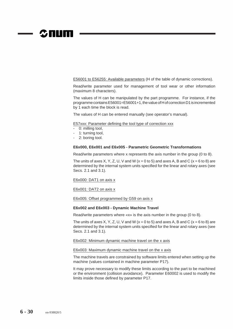
6 - 30 en-938820/5
E56001 to E56255: Available parameters (H of the table of dynamic corrections).
Read/write parameter used for management of tool wear or other information(maximum 8 characters).
The values of H can be manipulated by the part programme. For instance, if theprogramme contains E56001=E56001+1, the value of H of correction D1 is incrementedby 1 each time the block is read.
The values of H can be entered manually (see operator’s manual).
E57xxx: Parameter defining the tool type of correction xxx- 0: milling tool,- 1: turning tool,- 2: boring tool.
E6x000, E6x001 and E6x005 - Parametric Geometric Transformations
Read/write parameters where x represents the axis number in the group (0 to 8).
The units of axes X, Y, Z, U, V and W (x = 0 to 5) and axes A, B and C (x = 6 to 8) aredetermined by the internal system units specified for the linear and rotary axes (seeSecs. 2.1 and 3.1).
E6x000: DAT1 on axis x
E6x001: DAT2 on axis x
E6x005: Offset programmed by G59 on axis x
E6x002 and E6x003 - Dynamic Machine Travel
Read/write parameters where «x» is the axis number in the group (0 to 8).
The units of axes X, Y, Z, U, V and W (x = 0 to 5) and axes A, B and C (x = 6 to 8) aredetermined by the internal system units specified for the linear and rotary axes (seeSecs. 2.1 and 3.1).
E6x002: Minimum dynamic machine travel on the x axis
E6x003: Maximum dynamic machine travel on the x axis
The machine travels are constrained by software limits entered when setting up themachine (values contained in machine parameter P17).
It may prove necessary to modify these limits according to the part to be machinedor the environment (collision avoidance). Parameter E60002 is used to modify thelimits inside those defined by parameter P17.

Parametric Programming
en-938820/5 6 - 31
6
At power on, after a reset or an M02, these parameters are initialised with the value90000000 (+ or - according as it is the minimum or maximum).
FFGGHHIIJJJKKKLLLMMMNNNOOOPPPPPPPPPPPPQQQQQQQQQQQQRRRRRRRRRRRRSSSSSSSSSSSSSTTTTTTTTTTTTTUUUUUUUUUUUUUVVVVVVVVVVVVVWWWWWWWWWWWWXXXXXXXXXXXXYYYYYYYYYYYYZZZZZZ[[[[[[\\\\\\]]]]]]^^^^^^______``````aaaaabbbbbcccccLZ
E72002
ZaMinimumtravels(P17)
E62002
X
Z
To modify these limits, the programme should contain the following:
%28N..E62002= Za Declaration of the minimum dynamic
travel on ZN.. ...
REMARK During machining, the system applies the tool corrections to remainwithin the limits defined. For instance, for maximum travel, the tool'scutting edge cannot exceed dimension Za-LZ.
E69000 to E69002
E69000: Scaling factor
Read/write parameter.
The units are in thousandths.
E69001: Axis tilt on grinder
Read/write parameter.
The unit is ten-thousandths of a degree.
E69002: Axis tilt on grinder
Parameter used to declare a grinder inclination (X and Z axes orthogonal) in an axisgroup. The unit is ten-thousandths of a degree.
The angle of inclination is preserved after a reset.

6 - 32 en-938820/5
6.2.9.5 Group Axis Access Parameters
E7x000 to E7x007 - E7x100 and E7x101
Parameters where x represents the axis number in the group (0 to 8).
For parameters E7x000 to E7x008, the units of axes X, Y, Z, U, V and W (x = 0 to 5)and axes A, B and C (x = 6 to 8) are determined by the internal system units specifiedfor the linear and rotary axes (see Secs. 2.1 and 3.1).
E7x000: Position reference of an axis in the group
Read-only parameters (except for dynamic operators).
E7x001: Probed "on-the-fly" dimension for an axis in the group
Read/write parameters.
These parameters are used to directly read the axis positions during movement afteran NC priority interrupt (PLC IT inputs) programmed with G10 (see Sec. 4.11.5).
The measurement is stored in these parameters until:- the next interrupt is received- a manual or programmed (M02) reset is carried out.
When G10 is read in the part programme, these parameters can be initialised to99999999 from the programme so as to make a test after acquiring the dimension(should there be no interrupt before the programmed dimension).
E7x002: Minimum static machine travel
Read-only parameters.
This parameter is the image of machine parameter P17 (see E6x002 and E6x003).
E7x003: Maximum static machine travel
Read-only parameters.
This parameter is the image of machine parameter P17 (see E6x002 and E6x003).
E7x004: Direction of movement of the axes being interpolated
Read-only parameter.
This parameter is used only in conjunction with dynamic operators.
With linear interpolation, this parameter contains the incremental move for the currentblock on the axis whose physical address is identified by x.

Parametric Programming
en-938820/5 6 - 33
6
With circular interpolation, this parameter contains the component on axis x of thevector with length R tangent to the path (applies only to linear axes in the interpolationplane).
E7x005: Axis address assignment
Read/write parameters.
Read of these parameters gives the physical address of a programme axis (aprogramme axis is assigned to a physical axis by machine parameter P9).
When no physical axis is assigned to the programme axis, the parameter takes onthe value -1.
Examples:- if word N2 of parameter P9 has the value 05 (programme axis 5=W of group 1
assigned to physical address 2) in the first axis group, E75005=2 (physical axis2 assigned to programme axis 5),
- if word N8 of parameter P9 has the value 26 (programme axis 6=A of group 3assigned to physical address 8) in the third axis group, E76005=8 (physical axis8 assigned to programme axis 6),
- if no word of P9 has the value 13 (programme axis 3=U of group 2 is unassigned)in the second axis group, E73005=-1 (no physical axis assigned to programmeaxis 3).
Writing to these parameters can assign a different physical axis to a programme axis.
A physical axis must be freed before being assigned to a new programme axis (byassigning the value -1 to the parameter of the programme axis with which the physicalaxis was originally associated).
Example:- in an axis group, E75005=2 (physical axis 2 assigned to programme axis 5=W),- in the same axis group, E74005=8 (physical axis 8 assigned to programme axis
4=V),- to assign physical axis 8 to programme axis 5 (W):
• release physical axis 8 from programme axis 4 (E74005=-1),• assign physical axis 8 to programme axis 5 (E75005=8).
! CAUTION
A new physical axis assigned to a programme axis must be of the same nature as theprevious axis (linear or rotary axis, servo or not, modulo or with limited excursion, etc.).
A reset or end of programme (M02) restores the default conditions specified bymachine parameter P9.

6 - 34 en-938820/5
E7x006: Axis coupling
Read/write parameters.
Parameters used to create or cancel carrier/carried axis pairs.
These parameters apply to primary or secondary linear axes (programme axisnumber between 0 and 5).
The value «0» assigned to the parameter cancels the primary/secondary axis pairingto which the axis specified belongs and a «1» specifies that the axis is carried.
When the parameter related to one axis is modified, the parameter related to the otheraxis of the primary/secondary axis pair is automatically modified.
A reset reconfigures the axis pairs as specified by machine parameter P64.
Example:
E70006 = 0 Axes X and U are independentE72006 = 1 Axes Z and W are coupled.
E7x007: Axes programmed on diameter
Read-only parameters.
Only parameters E70007 (X axis) and E73007 (U axis) can be programmed ondiameter.
«0» means that these parameters are programmed on radius.«1» means that they are programmed on diameter.
E7x100: Interpolator position references
Read-only parameters.
This parameter contains the position references from the interpolators. Interaxiscalibration uses these references after transformation for computing corrections.
REMARK The interpolated references E7x100 (with or without transformation)are copied into the references used in servo-controls (E7x000) only forthe axes declared in machine parameters P2 and P3 (possibly modifiedby E9100x).

Parametric Programming
en-938820/5 6 - 35
6
E7x101: Interpolation speed limiting
Read/write parameters.
Write of this parameter limits the interpolation speed on logical axis x in the groupwhere it is programmed according to the relation:
V ipo (x) = P30 *E7x101100
However, the maximum speed on the axis is not modified.
The limit value accepted is between 0 and 100 (percent) (rounded off to the nearestinteger).
These parameters are forced to 100 percent at power on. They are all reset to 100percent after a reset.
Possible uses of this parameter:- Typical use: reserves part of the speed for geometric transformations carried out
downstream of the interpolation, for instance with RTCP with or without axis drivenin NM_AUTO mode (see supplementary programming manual).
- Special use with E7x101 = 0: axis x is assigned a zero speed:• if it is programmed alone in a block, it is ignored• if it is programmed with other axes, only the movements on the other axes are
carried out.
It should be noted that:- programming others than of that a CNC axis group or programming of an non-
existent axis returns error message 91- if the programmed value is negative or above 100, the system returns error
message 92.

6 - 36 en-938820/5
6.2.9.6 Spindle Access Parameters
E79000 and E79001
Read-only parameters (except for the dynamic operators).
E79000: Reference position of the spindle whose measurement is used by the groupto which it belongs
Position in ten-thousandths of a degree.
When the position is accessed by dynamic operators, it is expressed as 1/4096revolution modulo 216.
E79001: Speed demand for the spindle controlled by its group
The value is: (speed demand/max speed of the range) x 215.
In «normal» parametric programming, this parameter is a read-only parameter andgives the value programmed by «S» as a function of the spindle speed range, but notthe value calculated by the dynamic operators.
The reference value is encoded on 15 bits + sign bit.
! CAUTION
When this parameter is programmed by dynamic operators, the sign bit is used by thesystem only in state M05. Otherwise, it is forced to insure the direction of rotation
programmed by M03 or M04.
The spindle potentiometer is not active in this case.
E9010x, E9011x and E9020x
Read-only parameters (except by dynamic operators) where «x» is the spindlenumber (0 to 3).
These parameters allow any axis group to access any spindle.
E9010x: Spindle x position reference
(Same format as parameter E79000).
E9011x: Spindle x modulo
For additional information, see machine parameter P40.
E9020x: Spindle x speed setting
(Same format as parameter E79001).

Parametric Programming
en-938820/5 6 - 37
6
E9030x to E9033x
Read/write parameters where «x» is the spindle number (0 to 3).
The new values set for these parameters are saved until the next NC reset.
E9030x: Maximum spindle x indexing speed
Speed in rev/min (see machine parameter P43).
E9031x: Spindle x in-position window
Value expressed in internal units (see machine parameters P40 and P44).
E9032x: Spindle x indexing gain
Value expressed in rev/min/rev (see machine parameter P45).
E9033x: Spindle x indexing acceleration
Value expressed in rev/s2 (see machine parameter P32).
E9034x to E9035x
Read/write parameters where «x» is the spindle number (0 to 3).
These parameters are used to make sure the difference between the spindle speedset and the real speed remains within a tolerance interval and also, where required,to detect nonrotation of the spindle when the speed is below a minimum threshold.
E9035x
E9034x
Realspeed
Speed setting
Toleranceon Vx
Vx

6 - 38 en-938820/5
E9034x: Speed threshold below which spindle x is considered stopped
Parameter defining the speed threshold below which the spindle is considered to bestopped. This parameter is expressed in rpm. It is initialised with 10 at power on andcan be modified by programming. This parameter is also used as tolerance thresholdand detection of the speed reached.
E9035x: Tolerance interval coefficient
Parameter defining the tolerance interval coefficient as a function of the speed. Thisparameter expressed as 1/256 is initialised with 13 (i.e. 5 percent) at power on andcan be modified by programming.
REMARK In PLC variables %R12.W, bits %R12.0 to %R12.3 (spindles 0 to 3)indicate to the PLC that spindle rotation is correct and bits %R12.4 to%R12.7 indicate that the spindle is stopped (i.e. at a speed below thevalue declared in E9034x).

Parametric Programming
en-938820/5 6 - 39
6
6.2.9.7 Common NC Parameters
E80000 to E80050
Local read/write data parameters.
E8x000 to E8x999
Local read/write data parameters reserved for the system use.
These parameters are related to the inter-axis calibration (see installation andcommissioning manual).
E81xxx: Master axis position reference
E82xxx: Slave axis corrections with respect to the master axes
6.2.9.8 Machine Axis Access Parameters
E9yyxx
Parameters where xx represent the physical address of the axis (0 to 31).
An operation on these parameters stops movement at the end of the previous block.
E900xx, E910xx, E911xx and E920xx
Read/write parameters.
E900xx: Axis measurement
Read of measured or servo axes.
Write is not possible for servo axes.
E910xx: Servo or non-servo status of the axes
These parameters reflect the servo or non-servo status of an axis (a physical axis isdeclared servo or non-servo by machine parameter P3) and are used to modify thisstate.
A «1» in this parameter indicates that the corresponding axis is servo controlled anda «0» that it is non-servo.
A reset or end of programme (M02) reconfigures the axes as specified by machineparameter P3.

6 - 40 en-938820/5
E911xx: Homing status on an axis
These parameters indicate whether the axis homing procedure has been done.
A «1» indicates that a HOME has not been completed on the axis and a«0» that it hasbeen completed.
This parameter addresses the axes and spindles, e.g.:
If spindle 1 is measured, programming E91124 = 1 forces a NOT HOMED status forthe spindle. Since homing is automatic on spindles, this makes it possible to resetthe spindle position reference.
E913xx: Clampable axis enable state
This parameter enables or disables axis clamping by programming.
Example:- E91308 = 1: axis 08 can be clamped- E91308 = 0: axis 08 cannot be clamped.
A reset applies the settings of machine parameter P8 to the axes. The list of axes thatcan be clamped is sent to the PLC (by PLC variable %R24.L).
E920xx: Axis origin switch enable state
These parameters reflect the state of bit 14 of the axis port command word.
A «1» indicates that the switch is enabled and a «0» that it is inhibited.
The state of the control word can be read on all the measured axes of the machine.
Writing to this control word is possible only for non-servo axes.
A reset, end of programme (M02) or contact with the measurement sensor zeroautomatically cancels an enabled status of the switch.
In HOME mode, it takes on a value of «1» when the axis jog is engaged and «0» whenit is released or when the switch is encountered.

Parametric Programming
en-938820/5 6 - 41
6
E930xx to E936xx
Read-only parameters.
E930xx: State of the origin switches
These parameters reflect the state of bit 14 of the axis port status word.
A «1» indicates that the switch is active and the «0» that it is idle.
E931xx: Measured axis
A «1» indicates that the axis is measured.
This parameter is the image of machine parameter P2.
E932xx: Axis declared as rotary modulo 360 degrees
A «1» indicates that the axis is declared rotary modulo 360 degrees.
This parameter is the image of machine parameter P1 (word 1).
E933xx: Axis homing direction
A «1» indicates that the axis is moving in the negative direction in homing mode.
This parameter is the image of machine parameter P15 (word 1).
E934xx: Homing status without switch wiring
A «1» indicates that the origin switch is not wired on this axis.
This parameter is the image of machine parameter P15 (word 2).
E935xx: Axis (or spindle) in-position window
This parameter is used to define the position of an axis or a spindle. Its state is theimage of the bits of %R6.B to %R9.B transmitted to the PLC. However, if physicalaxis numbers 24 to 27 correspond to spindles, the associated parameters, E93524to E93527, indicate the spindle in-position status (spindle indexed by M19 orsynchronised spindle) and are the image of the bits of %R13.B transmitted to the PLC.
E936xx: Measurement encoder type
Parameter defining the measurement encoder type. It is the image of bits 25 and 26of machine parameter P34.
Values that can be assigned to the parameter:- 0: incremental encoder- 1: absolute encoder- 2: combined encoder- 3: ruler with encoded reference marks.

6 - 42 en-938820/5
E940xx and E942xx
Read/write parameters.
E940xx: Assignment of a slave axis (or spindle) to a master axis (or spindle)
These parameters are related to inter-axis calibration (see installation andcommissioning manual).
E941xx: Association of a slave axis (or spindle) with a master axis (or spindle)
The axes must be associated before slaving an axis to a master axis for duplicationor synchronisation (see duplicated and synchronised axes manual).
The associations can be defined by machine parameter P27 (see parameter manual)or in the part programme, e.g.:
E941xx = m The slave axis is denoted «x» and the master axis «m».If «m» = -1, the association of slave axis «x» with master axis «m»is cancelled.
In the current position coordinate page (AXIS) for an axis group, pressing thecontinuation «.../..» key calls a new page on which are displayed the slave axeswhose master axes belong to this group. These axes are identified by the symbolicname of the master axis (X, Y, etc.) followed by their own physical address.
E942xx: Axis/spindle switching
Parameter used with programmed association or reassociation of an axis or spindlemeasurement system with a motor reference output (dac) located at a differentaddress.
Example: E942xx = yy.
This setting associates motor reference output xx with axis or spindle measurementsystem at address yy.
In this case:xx (00 to 31): physical address of the axis or spindle motor reference outputyy (00 to 31): physical address of the measurement system.
If addresses xx and/or yy are not recognised, the system returns error message 92.
Restriction: reassociation is impossible and inoperative on QVN axes.
Parameters E942xx are saved after a reset.

Parametric Programming
en-938820/5 6 - 43
6
Typical example:
A spindle (@24) can be used as C axis (@4). The spindle and the C axis are drivenby the same motor, with different encoders....(USE AS SPINDLE)E94224=24(by precaution, programme:)E91004=0 (not slaved)......(USE AS C AXIS)E94224=04(by example, programme:)E91004=1 (C slaved)E91104=0 (HOMING completed)......
E950xx to E952xx
Read-only parameters.
E950xx: Axis reference offset
These parameters can only be written by interaxis calibration (see Installation andCommissioning Manual) or by the dynamic operators (see dynamic operatorsmanual).
E951xx: Position of the origin switch with respect to the machine origin
This parameter is the image of machine parameter P16.
E952xx: Axis measurement correction (or spindle)
E960xx to E963xx
Read/write parameters used for duplication or synchronisation (see duplicated andsynchronised axes manual).
E960xx: duplicated axis in automatic modes
If this parameter is a «1», the axis is duplicated in the automatic modes. If it is a «0»,it is not.
E961xx: duplicated axis in manual mode (JOG)
If this parameter is a «1», the axis is duplicated in manual mode (JOG). If it is a «0»,it is not.

6 - 44 en-938820/5
E962xx: synchronised axis
If this parameter is a «1», the axis is synchronised. If it is a «0», it is not.
E963xx: symmetrically driven axis
If this parameter is a «1», the axis is driven symmetrically. If it is a «0», it is not.
E970xx to E973xx
Read-only parameter.
E970xx: Maximum axis speed
Maximum speed in mm/min or deg/min.
E971xx: Axis acceleration at the work rate
Acceleration expressed in mm/s2 or deg/s2.
E972xx: Axis acceleration at high speed
Acceleration expressed in mm/s2 or deg/s2.
E973xx: Maximum authorised speed at angle crossings
This parameter is the image of machine parameter P33. Its value is specified in mm/minute.
E980xx to E983xx
Read-write parameters
E980xx: Axis servo-control coefficient
In the position servo-loop, this parameter is the proportional action coefficient appliedto the axis following error to obtain its speed reference. This parameter is the imageof machine parameter P21. It is expressed in 0.001 mm or degrees.
The value written is immediately applied to the servo-loop. However, after a RE_INIT(power up), the value of machine parameter P21 is reused.
E981xx: Axis acceleration anticipation time constant
When machining at very high speed, this parameter is used to programme the axisacceleration anticipation. After an initialisation, the value of machine parameter P19is reused.

Parametric Programming
en-938820/5 6 - 45
6
E982xx: Amplitude of the antistick pulse on reversal
This parameter is the image of machine parameter P19 (words 32 to 63). It isexpressed in micrometres.
E983xx: Time constant to absorb the antistick pulse
This parameter is the image of machine parameter P19 (words 64 to 95). Its valueis expressed in 1/100000 s.

6 - 46 en-938820/5
6.2.10 External E Parameter Programming Syntax
The programming syntax for external E parameters is given as Conway diagramsfollowed by programming examples.
6.2.10.1 Assignment of an External Parameter to an NC Function
Syntax
(5 digits)A
+
–
E
A NC function.
+ / - Sign.
E External parameter used as numerical value
Notes
External E parameters have integer values. When they are assigned to a function witha decimal value, the decimal point is implicit and depends on the format of thefunction.
When the value of the parameter is not compatible with the format of the function (toomany digits, etc.), the system reports an error.
Example
Use of an external parameter with NC addresses in different units.
Assignment of external parameter E80000 to addresses X and C.
N..E80000 = 18000 Declaration of the value of the
parameterG00 XE80000 The value of E80000 is equivalent to
18 millimetres (internal unit = µm)G00 CE80000 The value of E80000 is equivalent to
1.8 degrees (format C034, i.e.ten-thousandths of a degree)
It should be noted that if the feed rate F is programmed as FE80000 (example), thefeed rate F takes on the integer value declared in parameter E (in this case, thedecimal digits are excluded with F).

Parametric Programming
en-938820/5 6 - 47
6
6.2.10.2 Declaration of an External Parameter in the Programme
Syntax
Value on8 digits
max
E
L
(5 digits)
(1 to 3 digits)
–
* /
+
+
–
R
A
T
C
S
+
–
&
!
(5 digits)E =
U
The operations in this diagram are described in detail in Sec. 6.2.6.
Notes
When an operation result that is not an integer is assigned to an external parameter,the decimal digits are truncated. To keep a result with decimal digits, this result mustbe assigned to a variable L (see Sec. 6.1.10.2).
Example
Use of external parameters with arithmetic operations.
N..E80002 = 3150 Declaration of the value of E80002E80016 = 2400 Declaration of the value of E80016E80005 = E80002 / E80016 After the operation, E80005 takes on
the value 1 (truncation)L1 = E80002 / E80016 After the operation, L1 takes on the
value 1.3125N..

6 - 48 en-938820/5
6.2.10.3 Test on an External Parameter for a Conditional Branch
Syntax
Value on8 digits
max
E
L
(5 digits)
(1 to 3 digits)
–
* /
+
+
–
R
A
T
C
S
+
–
&
!
N . .(5 digits) =
>=
<=
<
>
G79 E
U
REMARK For tests on fractions, see Sec. 6.8.2.
Example
Use of an external parameter with a conditional test.
N.. ...N50 E56003 = E56003+1 Increment of the parameterG79 E56003 = > 10 N50 Condition: if E56003 ≥ 10, branch to
N50, else continueN..

Parametric Programming
en-938820/5 6 - 49
6
6.2.10.4 Examples of Use of External E Parameters
Examples
Use of the external parameters related to the choice of lines for graphic display(E31000 and E31001)
Drawing of paths using different types of lines.
%15N10 E31000=4 G00 X200 Z200N20 X50 Z150 Point a, no trace (stylus raised)N30 E31001=0 G01 Z125 ES+ EB10 Point b, solid lineN40 G03 X110 Z90 I75 K90 R35 ET Point cN50 E31001=1 G01 EA180 Z20 Point d, dotted lineN60 E31001=2 G00 X200 Z200 Point e, dashed lineN70 ...
X20
0
200
d c
b
X
Z
a
e

6 - 50 en-938820/5
Use of external parameters related to DAT1 (E6x000), tool correction (E50xxx,E51xxx, E52xxx, E55xxx) and the standard NC parameter E80000.
Execution of one of the three types of parts proposed by the programme. The partnumber is selected by the operator following the message in block N10 (see Sec. 6.7).������������������������
FFFFFFFFFGGGGGGGGGHHHHHHHHHIIIIIIIIIJJJJJJJJJKKKKKKKKKLLLLLLLLLMMMMMMMMNNNNNNNNOOOOOOOOPPPPPPPPPPPPPPPPPQQQQQQQQQQQQQQQQQRRRRRRRRRRRRRRRRRSSSSSSSSSSSSSSSSSTTTTTTTTTTTTTTTTTUUUUUUUUUUUUUUUUUVVVVVVVVVVVVVVVVVWWWWWWWWWWWWWWWWXXXXXXXXXXXXXXXXXYYYYYYYYYYYYYYYYYZZZZZZZZZZZZZZZ[[[[[[[[[[[[[[[\\\\\\\\\\\\\\\]]]]]]]]]]]]]]]^^^^^^^^^^^^^^^_______________```````````````aaaaaaaaaaaaaaabbbbbbbbbbbbbbbccccccccccccccccø
E (
L12)
ø D
(L1
1)
Hol
e di
a. C
(L1
0)
1
e
1
OP
A (L1)
B (L2)
R L19
1
d c
abX
Z
Assignment of variables
Variables L1 L2 L10 L11 L12 L19
Code A B C D E Radius
Part 1 70 25 30 40 50 4
Part 2 65 30 25 38 48 3
Part 3 60 35 20 36 46 2

Parametric Programming
en-938820/5 6 - 51
6
Main Programme%100E60000=-240000 (DAT1 ON X)E62000=-458678 (DAT1 ON Z)E50003=78500 (DIMENSION X) E51003=53470 (DIMENSION Z)E52003=800 (RADIUS 0.8) E55003=1 (ORIENTATION C1)N10 $0 ENTER PART NUMBER (1, 2 OR 3)E80000=$0N20 G79 E80000=1 N50N30 G79 E80000=2 N70N40 G79 E80000=3 N90G79 N10 Return to N10 if 1, 2 or 3 not selectedN50 L1=70 L2=25 L10=30 L11=40 L12=50 L19=4 $PART 1N60 G79 N100N70 L1=65 L2=30 L10=25 L11=38 L12=48 L19=3 $PART 2N80 G79 N100N90 L1=60 L2=35 L10=20 L11=36 L12=46 L19=2 $PART 3N100 G77 H101N120 M02
Subroutine%101N10 G00 G52 X-50 Z-100L0=E52003/1000N20 T03 D03 M06 (EXTERNAL TOOL R0.8)N30 S900 M40 M04L3=-L0+1*2+L10 (Xa) L13=L1+L0+1 (Za)N40 G42 XL3 ZL13 Point aN50 G92 S3500N60 G96 S250N70 G95 F0.2N80 G01 ZL1 Point bN90 XL11 EBL19 Point cN100 ZL2 Point dL4=L0+1*2+L12 (Xe)N110 XL4 Point eN120 G00 G40 G52 X0 Z0 G97 S900 M05

6 - 52 en-938820/5
Use of the external parameters related to the machine axes (E90xxx and E93xxx)
Automatic HOME locating program on two axes: X (axis 0), Z (axis 1), zero ORPOM.
The programme below is given for reference and must be adapted to the features ofthe particular machine.
For use of the axis address equivalence table (see Sec. 6.3).
%9990G79 N100 Branch to N100N10L1=90000+L0 E900xx: measurement of the axisL2=91000+L0 E910xx: slave axisL3=92000+L0 E920xx: origin switch enableL4=93000+L0 E930xx: state of the origin switchL6=91100+0 Homing statusEL6=1 Homing not performedEL2=0 EL1=-1000 EL2=1 L5=EL1/1000 Initialisation of the measurement with -1N20 G79 EL4=0 N30 Branch to N30 if the axis is not on the
switchG52 G00 L5=L5-1 @XL5 G79 N20 Back off the switch by 1 mm, sign
depending on the HOME directionN30 EL6=1 EL2=0 EL1=-50000000 EL3=1 EL2=1 Measurement initialisation at 50 m, sign
depending on the HOME directionG01 G52 @X0 G10 @L0>0 N40 Movement to the measurement origin
until reaching a value of zero (ifORPOM is non-zero , take this intoaccount in the comparison)
N40N100 G94 F1000@X=X L0=0 G77 N10 N40 Definition of address@X=Z L0=1 G77 N10 N40 equivalences:
@X: axis name, L0: axis numberN110 M02

Parametric Programming
en-938820/5 6 - 53
6
Use of the external parameters related to the current mode numbers (E41000) andmachine axes (E90xxx to E93xxx and E911xx)
The programme below is given for reference and must be adapted to the features ofthe particular machine.Automatic HOME locating programme for the C axis (physical address 3), zeroORPOM.
%1000N10 S100 M03 M40N20 M997N30 G79 E41000=4 N140 =4: Rapid modeN40 G79 E41000=6 N140 =6: Test modeN50 G04 F1N60 M.. Encoded M functions defined by the
machine manufacturerN70 G04 F1N80 M64 M05N90 E91103=1 Homing not performedN100 E91003=0 E92003=1
E910xx: Axis non-servoE90003=990000 E91003=1 E920xx: Enable HOME switch
E900xx: Overwrite axis pos'nE910xx: Axis servo
N110 L5=E90003/10000 +180 E900xx: Read back pos'n + 180N120 G94 F200N130 G01 G52 CL5 G10 @3<50 N150 Movement to HOME (if ORPOM was
non-zero, take it into account in thecomparison)
N140 G79 N100N150
Programme %1001 is used to make the C axis non-servo (spindle)
%1001N10 M997N20 G79 E41000=4 N50N30 G79 E41000=6 N50N40 M.. Encoded M function defined by the
machine manufacturerN50 M998

6 - 54 en-938820/5
6.3 Address Equivalences
ADDRESS EQUIVALENCE
@A = A@E = E@I = I@M = M@Q = Q@U = U@Y = Y
L/@
@B = B@F = F@J = J@N = N@R = R@V = V@Z = Z
@C = C@G = G@K = K@O = O@S = S@W = W
@D = D@H = H@L = L@P = P@T = T@X = X
This table is used to specify theequivalence between two axes. Forinstance, it allows a programme to bewritten for another axis group, such asUW.
The symbol @ followed by an address (Ato Z) specifies an equivalent axis.
The declaration of an equivalent addressis programmed by:
A""Z
@ =
A""Z
The assignment of a value to an equivalent function is programmed by:A""Z
@ followed by the value
Example :
@ X = 300 @ X = 300 is equal to U 300
The address equivalence table is reset at power on, by a reset or by M02 (@A = A,@ B = B, ..., @ Z = Z).
The declaration of a new equivalent address (
A""Z
@ =
A""Z
) suspends
preparation of the block in which it is programmed until execution of the previous blockis completed.
The address equivalence table is displayed by pressing the «Programme variable»key L/@ (see example in Sec. 6.2).

Parametric Programming
en-938820/5 6 - 55
6
6.4 Transfer of the Current Values of L Variables and E Parameters into thePart Programme
G76 Transfer of the current values of L variables and E parameters into thespecified programme or programme section.
This function is used to update the contents of a file called by addresses H.. and/orN.. N..
The file of L variables and E parameters is updated with the new contents of thecorresponding active data.
Syntax
N.. G76 [H..] [N.. N..]
G76 Transfer of the current values of L variables andE parameters into the programme specified.
H.. Specification of the programme into which the valuesare transferred.
N.. N.. Specification of the programme section into which thevalues are transferred.
Notes
The parameters to be transferred must be located at the beginning of blocks:L variables and E parameters located after another function in a block are ignored.
The specification of an L variable or E parameter must be followed by the sign «=»and at least ten characters (spaces, algebraic sign, numbers, decimal point)designed to be replaced by a new value.
Failure to comply with this rule returns error message 97.

6 - 56 en-938820/5
Examples
Transfer of the values of L and E into the current programme
In the example below, only parameters L101, E80001, L4 and L6 are modified. Theother parameters are ignored.
N..N40 G76 N100 N120N..N100 ..L101=.......... E80001=..........L4=.......... G04 E52002=.......... E52002 is not modified as it is located
after G04L6=..........G01 X100 L3=.......... L3 is not modifiedN120N..
Transfer of the values of L and E into a subroutine
%125N10 G77 H200 N50 N80 Execution of blocks N50 to N80 of
%200N..N.. Execution of the programme after
modification of the parameters by %200N..N600 G76 H200 N50 N80 Update of the fileN610 M02
%200N10 ...N..N50L1=.......... E52002=..........E80004=..........N80N..

Parametric Programming
en-938820/5 6 - 57
6
6.5 Message Display with Wait for an Operator ResponseThe «$» character can be used as variable in a parametric expression. It causes theprogramme to wait for an operator entry.
The block containing the parametric expression can be preceded by a messageindicating the type of data to be entered.
Syntax
L../E.. = Expression depending on $
L../E.. Programme variable or external parameter.
$ Variable whose value must be entered by the operator.
Cancellation- end of programme (M02),- reset.
Notes on Operation
Upon reading the «$» character associated with a variable (possibly accompanied bya message with a maximum of 39 characters), the system stops the programme andwaits for the operator to type an entry.
The characters typed are echoed on the message line of one of the following pages:- Information page (INFO.)- Current position with respect to OP page (AXIS)- Trace during machining page (TRACE DURING MACHINING).
The entry can be numerical characters or one alphabetic character. Each type ofentry corresponds to a specific use.

6 - 58 en-938820/5
Numerical entry
The number of digits entered must not exceed eight plus sign and decimal point.
The limit values are as follows:- Integer: < 99999999 or < -99999999- Positive decimal: < 0.0000001 or < 9999999.9- Negative decimal: < -9999999.9 or < -0.0000001.
The operator must confirm the entry by pressing the Enter key on the keyboard(otherwise the system does not proceed to the next block).
REMARK Before pressing Enter, the characters entered can be deleted by theDelete key.
Alphabetic entry
Only the first character entered is analysed.
Any capital letter from A to Z is accepted. Each letter returns a value:A returns 1B returns 2and so forth to Z = 26.
REMARK The first character entered is analysed by the system which automaticallyproceeds to the next blocks (it is not necessary to confirm the entry byEnter).
It should be noted that in a test programme, each numerical value from 1 to 26corresponds to alphabetic characters A to Z.
Example
N.. ...N50 E80000=50$0 ENTER THE VALUE OF X = Display of the message for the operatorN60 L0=E80000 + $ Wait for entry of the valueN..

Parametric Programming
en-938820/5 6 - 59
6
6.6 Display of Messages with Parametric ValueThe «$» character can be used as first term of a parametric expression whose valueis displayed after being calculated by the system.
The block containing the parametric expression can be preceded by a messageindicating the name of the variable displayed.
Syntax
$ = expression
$ Variable whose value is displayed.
Cancellation- end of programme (M02),- reset.
Notes
An expression «$=...» in a block after the branch function (G79) cannot be used asa branch condition.
Example
N..L0=0 Initialisation of variable L0N90 L0=LO+1 Increment of L0
$0 EXECUTION OF SUBROUTINE % Display of the first part of the message$= L0 Display of the value following the
previous message
G77 HL0 Call to subroutine %(L0)G79 L0<5 N90 Condition: if L0 < 5, branch to block
N90, else continueN..

6 - 60 en-938820/5
6.7 Reading the Programme Status Access Symbols
The programme status access symbols allow all modal functions to be read. Theycan be used to save the programme context when a subroutine is called. The contextcan then be restored when execution of the subroutine is finished.
These read-only symbols are accessible by parametric programming.
These symbols can be:- symbols to access the data in the current block- symbols to access the data in the previous block.
The same data are accessible in the previous block as in the current block. Thesymbols are the same, but are preceded by two dots (instead of only one).
The only reason for accessing the data in the previous block is when execution of thecurrent block is suspended by programming of function G999. The data are those ofthe last executable block (or possible the last block already executed).
6.7.1 Symbols for Accessing the Data of the Current or Previous Block
The symbols can be:- symbols addressing Boolean values- symbols addressing numerical values.
General Syntax
Variable = [• symbol] or [•• symbol]
Variable L programme variable, symbolic variable [symb], Eparameter.
[• symbol] Data of the current block. Symbol between squarebrackets, preceded by a dot.
[•• symbol] Data of the previous block. Symbol between squarebrackets, preceded by two dots.

Parametric Programming
en-938820/5 6 - 61
6
6.7.1.1 Symbols Addressing Boolean Values
The symbols addressing Boolean values associated with programmed functions areused to determine whether the functions are active or not.
The Boolean values are defined by 0 or 1.
Addressing G Functions
[•BGxx] G function addressing.
The symbol [•BGxx] is used to determine whether the G functions specified by xx are
enabled or inhibited, e.g.:
[•BGxx]=0: function Gxx inhibited
[•BGxx]=1: function Gxx enabled
List of G Functions
[•BG00] [•BG01] [•BG02] [•BG03] [•BG17] [•BG18] [•BG19][•BG20] [•BG21] [•BG22] [•BG29] [•BG40] [•BG41] [•BG42][•BG43] [•BG70] [•BG71] [•BG80] [•BG81] [•BG82] [•BG83][•BG84] [•BG85] [•BG86] [•BG87] [•BG88] [•BG89] [•BG90][•BG91] [•BG93] [•BG94] [•BG95] [•BG96] [•BG97]
Addressing M Functions
[•BMxx] M function addressing.
The symbol [•BMxx] is used to determine whether the M functions specified by xx are
enabled or inhibited, e.g.:
[•BMxx]=0: function Mxx inhibited
[•BMxx]=1: function Mxx enabled
List of M Functions
[•BM03] [•BM04] [•BM05] [•BM07] [•BM08] [•BM09] [•BM10] [•BM11][•BM19] [•BM40] [•BM41] [•BM42] [•BM43] [•BM44] [•BM45] [•BM48][•BM49] [•BM64] [•BM65] [•BM66] [•BM67] [•BM997] [•BM998] [•BM999]

6 - 62 en-938820/5
6.7.1.2 Symbols Addressing Numerical Values
The symbols addressing numerical values are used to read the modal data of thecurrent block or the previous block.
Addressing a Value
[•Rxx] Addressing a value.
The symbol [•Rxx] is used to address a value corresponding to the elements specifiedby xx.
[•RF] Feed rate (units as programmed by G93, G94 or G95).
[•RS] Spindle speed (G97: format according the spindlecharacteristics declared in machine parameter P7).
[•RT] Tool number.
[•RD] Tool correction number.
[•RN] Number of the last sequence (block) encountered.If the block number is not specified, the last numberedblock is analysed.
[•RED] Angular offset.
[•REC] Spindle orientation (milling).
[•RG4] Programmed dwell (G04 F..).This function, although nonmodal, may remain stored.Its value can therefore be read if the system is in stateG999 of G998.
[•RG80] Number of the G function branching to the subroutine.In a subroutine called by a G function, the number of thecalling function is addressed by [•RG80]; in state G80,its value is zero.
[•RNC] Value of NC (spline curve number).
[•RDX] Tool axis orientation.Defined by the following signs and values:= +1 for G16 P+ or -1 for G16 P-= +2 for G16 Q+ or -2 for G16 Q-= +3 for G16 R+ or -3 for G16 R-
[•RXH] Nesting level of the current subroutine (up to 8 levels).= 1: main programme= 2: first nesting level= 3: second nesting level, etc.

Parametric Programming
en-938820/5 6 - 63
6
Example
%100N10 G00 G52 X0 Z0 G71N..N40 G97 S1000 M03 M41N50 M60 G77 H9000 Tool check subroutine callN..N350 M02
%9000VAR[GPLANE] [MRANGE] [MDRN] [GINCH] [GABS] Symbolic variables (see Chapter 7)[XRETURN] [YRETURN] [ZRETURN]ENDV
$ CONTEXT SAVEN10 [GPLANE]=20*[•BG20] [GPLANE]=21*[•BG21]+[GPLANE] Interpolation plane [GPLANE]=22*[•BG22]+[GPLANE]N20 [MRANGE]=40*[•BM40] Speed range [MRANGE]=41*[•BM41]+[MRANGE]N30 [MDRN]=03*[•BM03] [MDRN]=04*[•BM04]+[MDRN] Direction of rotation [MDRN]=05*[•BM05]+[MDRN]N40 [GINCH]=70*[•BG70] Inches [GINCH]=71*[•BG71]+[GINCH]N50 [GABS]=90*[•BG90] Absolute [GABS]=91*[•BG91]+[GABS][XRETURN]=E70000[ZRETURN]=E72000N60 G90 G70 G00 G52 Z0N70 G52 X-100 Z-100 M05 Tool check positionN80 G52 G10 Z-500N90 G52 Z0N100 G52 Z [ZRETURN] Return to Z positionN110 G52 X [XRETURN]G[GPLANE] M[MRANGE]M[MDRN] G[GINCH] G[GABS] Restore context

6 - 64 en-938820/5
6.8 General Diagrams of Parametric ProgrammingThe following symbols are used in the diagrams below:
[•symbol] or [••symbol]: Programme status access symbols
[symb]: Symbolic variables
These programming tools are defined in this programming manual (Sections 6.7 and7.3) and the supplementary programming manual (Chapter 2).
6.8.1 Load of a Parametric Expression
Syntax
–
* /
+
+
–
R
A
T
C
S
+
–
&
!
=
[symb]
L . .
E . .
$
$
[symb] E . .
L . .
[.symbol]
number
U

Parametric Programming
en-938820/5 6 - 65
6
6.8.2 Comparison for Conditional Branch
Syntax
–
* /
+
+
–
A
T
S<
>
&
!
=
[symb]
L …
E …
$
[symb] E . .
L . .
number
.R
.B …
G79
+
–
N …
R
C
[.symbol]
U
Note on > = < Tests on Fractions
In tests using > = < on fractions, the test may return false whereas the system displaysa true result. This is especially the case for a loop.
Example:...N10.........L1 = L1 + 0.6 G79 L1 < 6 N10...It should be noted that after 10 loop iterations, L1 is equal to 6 (on the display) whereasthe computation result gives 5.99. An additional iteration is therefore required. Since0.6 in binary is not exact, there is always a remainder.
In hexadecimal = ,99999999 ... soit 1/2 + 1/16 + 1/256 + 1/512 + 1/4096 + 1/8192+ ....

6 - 66 en-938820/5
In practice, for incrementation with fractions, always make the test on a lower valueconsistent with the incrementation.
Example:For 0.6, with 10 iterations, test on 5.9For 0.1, with 10 iterations, test on 0.96For 0.01, with 10 iterations, test on 0.096.

Programme Stack - L Variables and Symbolic Variables
en-938820/5 7 - 1
7
7 Programme Stack - L Variables and SymbolicVariables
7.1 Programme Stack 7 - 37.1.1 Use of the Stack 7 - 37.1.2 Stack Allocation 7 - 3
7.2 Saving and Restoring L Variables 7 - 47.2.1 PUSH Function 7 - 47.2.2 PULL Function 7 - 5
7.3 Symbolic Variables 7 - 77.3.1 Declaring Symbolic Variables - VAR and
ENDV Functions 7 - 77.3.2 Using Symbolic Variables in ISO
Programmes 7 - 87.3.3 Acquisition of Variables from the Stack
of Another Axis Group:Function VAR H.. N.. N.. 7 - 11
7.3.4 Deleting Symbolic Variables from theStack 7 - 13
7.3.4.1 Automatic Deletion of Symbolic Variables 7 - 137.3.4.2 Programmed Deletion of Variables:
DELETE Function 7 - 13

7 - 2 en-938820/5

Programme Stack - L Variables and Symbolic Variables
en-938820/5 7 - 3
7
7.1 Programme StackEach axis group (including graphic axis groups) is allocated a stack located at thebottom of the memory.
7.1.1 Use of the Stack
The stack is used to:- save and restore L programme variables,- assign symbolic variables,- save spline curve coefficients.
7.1.2 Stack Allocation
The stack size is defined by machine parameter P58 (see parameter manual).

7 - 4 en-938820/5
7.2 Saving and Restoring L Variables
7.2.1 PUSH Function
PUSH Saves the values of the L variables on the stack.
Syntax
PUSH Lm - Ln
PUSH Function forcing save of the L variable values.
Lm - Ln L variable numbers from m to n (inclusive) whosevalues are to be saved, i.e.:- 0-19,- 100-199,- 900-959.
Notes
The PUSH function must be the first word in a block (no sequence number).
Saving variables spanning different ranges of numbers by one PUSH is prohibited,e.g.:
Saving the values of L1-L19 and L100-L110
Right:
PUSH L1 - L19 Saves the values of L1 to L19PUSH L100 - L110 Saves the values of L100 to L110
Wrong:
PUSH L1 - L110

Programme Stack - L Variables and Symbolic Variables
en-938820/5 7 - 5
7
7.2.2 PULL Function
PULL Restores the values of the L variables.
Syntax
PULL Lm - Ln
PULL Function restoring the values of the L variables.
Lm - Ln L variable numbers from m to n (inclusive) whosevalues are restored, i.e.:- 0-19,- 100-199,- 900-959.
Notes
The PULL function must be the first word in a block (no sequence number).
The PULL function:- does not delete the values from the stack,- allows variables saved by a PUSH to be restored several times by PULL,- can cause a stack overflow after a series of PUSH-PULL operations (in this case,
the system returns error message 195).

7 - 6 en-938820/5
Example
Restore by PULL of the values of Lm to Ln saved by the last PUSH on the same setof variables.
%1 %1" "L0 = 1 L0 = 1" "
L0-L10
L0L1""
L10
L0-L10
L0L1""
L10
L0-L11
L0L1""
L11
Stack
Stack
Overwritesthe old set withthe same name
Restore ofthe last PUSHL0 = 2 inboth cases
PUSH L0-L10 PUSH L0-L10" "L0 = 2 L0 = 2" "PUSH L0-L10 PUSH L0-L11" "PULL L0-L10 PULL L0-L11 L0 = 2" "PULL L0-L10 PULL L0-L10 L0 = 1
A PULL from Lm to Ln restores only the variables saved in the main programme orcurrent subroutine or those from lower nesting levels (to be valid, a PULL must alwaysbe preceded by a PUSH).
%1 %2" "
L0-L10
L0"""
L10
Stack
Prohibited:The PUSH setis lost onreturning from N2
PUSH L0-L10 PULL L0-L10" "G77 H2 G77 N1 N2" "
PULL L10-L12"N1"PUSH L10-L12"N2

Programme Stack - L Variables and Symbolic Variables
en-938820/5 7 - 7
7
7.3 Symbolic VariablesVariables declared with symbolic names. The use of symbolic variables allows thenumber of variables used in parametric programming to be extended.
7.3.1 Declaring Symbolic Variables - VAR and ENDV Functions
Symbolic variables are declared between square brackets and are denoted [symb]in the syntax defined below.
Symbolic variables are always declared between functions VAR and ENDV.
VAR Symbolic variable declaration.
VAR is the keyword enabling symbolic variable declaration.
ENDV End of symbolic variable declaration.
ENDV is the keyword defining the end of symbolic variable declaration.
Syntax
VAR [symb]ENDV
VAR Symbolic variable declaration.
[symb] Symbolic variables with up to 8 alphanumericcharacters, the first of which is always alphabetic.
ENDV End of symbolic variable declaration.

7 - 8 en-938820/5
Notes
Functions VAR and ENDV must be the first words in the block (no sequence number).
VAR must be separated from the symbolic variable(s) by a space.
It should be noted that spaces are recognised as characters when writing a symbolicvariable. If a variable name includes a space, the space must always be included inthe name entered. Otherwise, the system returns error message 198.
ENDV must be the only word in the block.
Example:
VAR [INDEX] [RD12] [PHASE2]ENDV only word in the block
7.3.2 Using Symbolic Variables in ISO Programmes
A symbolic variable declaration suspends preparation of the block to which thevariables belong until execution of the previous block is finished (according to thesame principle as variables L100 to L199; see 6.1, programming notes).
Symbolic variables have real values.
Symbolic variables can be:- assigned to all the ISO programming functions,- used in parametric expressions,- associated where applicable with L programme variables and E external
parameters.
The programmer can access only the symbolic variables declared in the mainprogramme or subroutine or those from lower nesting levels.
Programming axes by variable L or parameter E defined by symbolic variable
The system provides the possibility of programming axes by variable L or parameterE defined by symbolic variables.
The number of the variable L or parameter E used is assigned to symbolic variable[symb...]. Example:
VAR[symb1]=80000 Parameter E number[symb2]=0 Variable L numberENDV......... XE[symb1] X axis programming (XE80000)... BL[symb2] B axis programming (BL0)

Programme Stack - L Variables and Symbolic Variables
en-938820/5 7 - 9
7
REMARK If X[symb2] or XL0 or XL[symb2] is programmed, the value specified bythe symbolic variable or variable L is in mm or in degrees if the axis isrotary.If XE80000 or XE[symb1] is programmed, the value specified byparameter E (set or not) is defined in the internal system unit (see Sec.2.1), by default µm or 0.001 degree if the axis is rotary.
Other Uses of Symbolic Variables
Symbolic variables can be used:- to create tables or arrays,- with structured branch and loop commands.
For further information, refer to the supplementary programming manual.
Example
Use of symbolic variables for machining a semielliptical shape
%35M999VAR[XSHIFT] = 50 [CLEAR] = 10[MAJ RAD] = 40 [MIN RAD] = [MAJ RAD][SPSPD] = 900 [DRN] = 04 [RANGE] = 40 Variable
[FDRATE] = 0.2 [CSS] = 100 declaration
[PITCH] = 5 [STRTANG] = 0 [ENDANG] = 180 [COS] [SIN]ENDVL1 = [MAJ RAD] + [CLEAR]N10 G0 G52 X0 Z0N20 T1 D1 M06 (BUTTON TOOL R=3)N30 G97 S [SPSPD] M [DRN] M [RANGE]$ MACHININGN40 G0 X- [CLEAR] ZL1N50 G1 G42 Z [MAJ RAD]N60 G92 S4000N70 G96 S [CSS]

7 - 10 en-938820/5
N80 X0 G95 F [FDRATE][SIN] = [MAJ RAD] * S [STRTANG][COS] = [MIN RAD] * C [STRTANG]X [SIN] Z [COS][STRTANG] = [STRTANG] + [PITCH]G79 [STRTANG] = < [ENDANG] N80 + 1N90 G1 X- [CLEAR]N100 Z-L1N110 G0 G40 XL1N120 G52 X0 Z0 G97 S900 M05N130 M02
Representation of machining
OP Z
X
[MIN
RA
D]
(by
radi
us)
[MAJ RAD]
[CLE
AR
]
[X D
AT
]
L1

Programme Stack - L Variables and Symbolic Variables
en-938820/5 7 - 11
7
7.3.3 Acquisition of Variables from the Stack of Another Axis Group:Function VAR H.. N.. N..
VAR H.. N.. N.. Acquisition of variables from the stack of another axis group.
Function VAR H.. N.. N.. is used to read the symbolic variables declared in anotherprogramme from the stack of another axis group.
Syntax
VAR H.. :s N.. N.. +i +j
VAR Acquisition of variables from the programme stack ofanother axis group.
H.. Number of the programme or subroutine from where thesymbolic variables are to be fetched.
:s Number «s» of the memory area where programme H..is located (s can have any value between 0 and 3 afterthe character :)Argument :s is optional.(see details below on :s)
N.. N.. Numbers of the first and last block defining the limitbetween which the symbolic variables are located.(see details below on N.. N..)
+i +j Offset with respect to blocks N.. and N..+i with respect to the first block,+j with respect to the last block.
Notes
When a variable acquired by VAR N.. N.. has the same name as a variable alreadydeclared in the current programme or subroutine, the current one's value is overwritten.

7 - 12 en-938820/5
Details on Area Number :s
An independent axis group (PLC group) whose programme is located in a protectedmemory area (area 1, 2 or 3) can read variables located in area 0 if the NC is not inan edit mode. Otherwise, execution of the independent axis group programme issuspended until the NC leaves the edit mode.
If :s is not specified, the programme is searched for:- from area 0 to area 3 for the NC groups,- from area 1 to area 3 for the independent groups.
Details on Blocks N.. N..
If programme number H.. is not specified, the limits from N.. to N.. are searched forin the current programme or subroutine.
If the second block number N.. is not specified, only the variables in block N.. are read.
Diagram of the Syntax
:s
N..
Start ofblock
Bloccontinuation
VAR H..
+j
N..+i
Example
%1 %2N10 ... N10N.. N..VAR H2 N50 N60 L0=[I] L1=[T(1,3)] VARN.. N50 [I] = 3 [J] = 4
[T(2,3)] = 3 , 4 = 5 , 6N60 = 7 , 8ENDV

Programme Stack - L Variables and Symbolic Variables
en-938820/5 7 - 13
7
7.3.4 Deleting Symbolic Variables from the Stack
The variables are not deleted until the block preceding the deletion command hasbeen executed.
7.3.4.1 Automatic Deletion of Symbolic Variables
A return from a subroutine deletes all the variables declared in the subroutine andreleases the space they occupied on the stack.
The end of programme command (M02) or an operator reset deletes all the variablesand reinitialises the stack.
7.3.4.2 Programmed Deletion of Variables: DELETE Function
DELETE Deletion of symbolic variables from the programme or subroutine.Deletes the global variables from the stack.
Syntaxe
DELETE * [symb1]/[symb2]…
DELETE Deletes the symbolic variables from the programme orsubroutine.Deletion of the global variables from the stack.
* When the variables names are preceded by thecharacter *, the variables to be deleted are searched forin the entire stack.When the variable names are not preceded by thecharacter *, the search for the variables to be deleted islimited to the variables declared in the main programmeor subroutine.
[symb1]/[symb2]… Variables to be deleted.

7 - 14 en-938820/5
Notes
The DELETE function:- must be the first word in the block (no sequence number),- must be followed by at least one space but there must be no spaces in the list of
variables,- is followed by the list of variables and arrays to be deleted; the variables are
separated by the character /.
Only the first four letters of the keywords are significant for the system. For instance,DELE is equivalent to DELETE.
Example
DELE [IX]/[TAB1]/[PROF1] Deletion of variables
DELE *****[IZ]/[TAB3]/[PROF2] Deletion of variables from the stack

Programming of Error Numbers and Messages
en-938820/5 8 - 1
8
8 Programming of Error Numbers and Messages
8.1 General 8 - 38.1.1 Error Numbers 8 - 38.1.2 Error Messages 8 - 3
8.2 Creating Error Messages 8 - 3

8 - 2 en-938820/5

Programming of Error Numbers and Messages
en-938820/5 8 - 3
8
8.1 GeneralError numbers can be included for analysis in the programmes and subroutines.
The error numbers can be accompanied by a message.
The errors detected by the programmes are processed and displayed in the sameway as the errors detected by the NC software.
8.1.1 Error NumbersThe errors created can be numbered from 1 to 9999.
The error number is programmed after the address E followed by a decimal point. Forinstance, to create error 503, programme:E.503
This programming causes the following display:error E.503 block N..
8.1.2 Error MessagesWhen the error number is accompanied by a message, programming E.503 resultsin the following display:Error 503 - block N..SPINDLE NOT INDEXED.
8.2 Creating Error MessagesThe messages are contained in a list of programmes numbered from %20000 to%29900 in 100-block increments (maximum 100 messages per programme).
Each block of a message programme (%20000 to %29900) begins with the blocknumber N.. corresponding to the error number, possibly followed by the character $and the message.
REMARK There must always be a space between the symbol $ and the message.
The third and fourth digits from the right of the error programme number are the sameas the number of the error they contain. For instance, programme %2xx00 and errorsNxx00.
Example:
Programme of messages 1 to 99
%20000 (ERRORS 1 TO 99)N0001 $ ...
to
N0099 $ ...
Etc. up to programme %29900 (see below)

8 - 4 en-938820/5
Programme of messages 9900 to 9999
%29900 $ ... (ERRORS 9900 TO 9999)N9900 $ ...N..N..N..N..N9999 $ ...
REMARKS When the blocks following an error number are unnumbered, they mayprovide additional information to the message displayed. In case of anerror, these blocks are not displayed (the list of errors can be consulted).
When an error created has the same number as a standard NUM error,the error created takes precedence.
Example
Programming with error numbers and messages
Error message programme
%20500 (ERRORS 500 to 599)N501 $ DIMENSION NOT POSITIVEN502 $ G FUNCTION MISSINGN503 $ SPINDLE NOT INDEXEDN..N540 $ MACHINE CONDITIONS NOT SATISFIED- OIL PRESSURE LOW- SEE DETAIL ON PLC MESSAGEN..N..N..N..N..N599 ...

Programming of Error Numbers and Messages
en-938820/5 8 - 5
8
Part programme
%123N10 ...N..N150 G108 Cycle calling a subroutineN..N.. M02
Subroutine
%10108N..N..G79 L0=0 N300 Test for error 501, jump to block N300 if
the condition is not satisfied and displaythe message
N..N..IF E10002=1 AND E10020= 0 THEN E.540 Test for error 540ENDIN..N300 E.501 Error 501N..

8 - 6 en-938820/5

Function Summary Tables
en-938820/5 A - 1
A
Appendix A Function Summary Tables
A.1 G Function Summary Table A - 3
A.2 M Function Summary Table A - 17
A.3 Additional Function Summary Table A - 22

A - 2 en-938820/5

Function Summary Tables
en-938820/5 A - 3
A
A.1 G Function Summary Table
The functions initialised at power on are identified by «*».
G00: Linear interpolation at high speed (see Sec. 4.4)
X
Z
Syntax:N.. [G90/G91] G00 [R+/R-] X.. Z..
Cancellation:G01/G02/G03/G33.
G01*: Linear interpolation at programmed feed rate (see Sec. 4.5.1)
X
Z
Syntax:N.. [G90/G91] G01 [R+/-] X.. Z.. [F..]
Cancellation:G00/G02/G03/G33.
G02: Clockwise circular interpolation at programmed feed rate (see Sec. 4.5.2)
X
Z
R
I-KSyntax:N.. [G90/G91] G02 X.. Z.. I.. K.. / R.. [F..]
Cancellation:G00/G01/G03/G33.
G03: Counterclockwise circular interpolation at programmed feed rate (see Sec. 4.5.2)
Syntax:N.. [G90/G91] G03 X.. Z.. I.. K.. / R.. [F..]
Cancellation:G00/G01/G02/G33.
X
Z
R
I-K

A - 4 en-938820/5
G04: Programmable dwell (see Sec. 4.15.1)
60
30
1545
Syntax:N.. G04 F..
Cancellation:End of block.
G05: Programming a movement on the inclined axis (see Sec. 4.16.2)
Syntax:N.. [G90/G91] [G00/G01] G05 X..
Cancellation:End of block.
G06: Spline curve execution command (see Sec. 4.13.2.2)
Syntax:N.. G06 NC..
Cancellation:End of block.
G07: Initial tool positioning before machining along an inclined axis (see Sec. 4.16.2)
Syntax:N.. [G90] [G00/G01] G07 X.. Z..
Cancellation:End of block.
G09: Deceleration at end of block before continuation on next block (see Sec. 4.6)
Without G09
εpWith G09Syntax:
N.. G09 [G00/G01/G02/G03] X.. Z.. [F..]
Cancellation:End of block.

Function Summary Tables
en-938820/5 A - 5
A
G10: Interruptible block (see Sec. 4.11.5)
Syntax:N.. [G40] [G04 F..] [G00/G01/G02/G03] X.. Z.. G10 [:n] [+X.. or F..] [@n < >Value] N.. [+ Number] [EF..]
Cancellation:End of block.
G12: Overspeed by handwheel (see Sec. 4.15.3)
Feed rate
Syntax:N.. [G01/G02/G03] G12 X.. Z.. [F..] [$0 ...]
Cancellation:End of block.
G16*: Definition of the tool axis orientation with addresses P, R (see Sec. 4.8.2)
X
Z
P+
R+
Syntax:N.. G16 P±/R±
Cancellation:G16 P±/R±.
G20*: Programming in polar coordinates (X, Z, C) (see Sec. 4.14.1)
Syntax:N.. [G40] G20 [G00/G01] [X.. Z.. C..] [F..]
Cancellation:G21 and G22.
G21: Programming in cartesian coordinates (X, Y, Z) (see Sec. 4.14.3)
C
X
Syntax:N.. [G40] G21 [G00/G01] [G41/G42] [X.. Y.. Z..] [G94 F..]
Cancellation:G20.

A - 6 en-938820/5
G22: Programming in cylindrical coordinates (X, Y, Z) (see Sec. 4.14.4)
C
ZSyntax:N.. [G40] G22 [G00/G01] [G41/G42] [X.. Y.. Z..] [G94 F..]
Cancellation:G20.
G23: Circular interpolation defined by three points (see Sec. 4.5.3)
Syntax:N.. [G90/G91] G23 X.. Z.. I.. K.. [F..]
Cancellation:End of block.
G33: Constant lead thread cutting (see Sec. 4.9.2)
X
Z
K P
Q
Syntax:N.. G33 X.. Z.. K.. [EA..] [EB..] P.. [Q..] [R..] [F..] [S..]
Cancellation:End of block.
G38: Sequenced thread cutting (see Sec. 4.9.3)
Thread
Z
X
Thre
ad
Syntax:N.. G38 X.. Z.. K..
Cancellation:G00/G01/G02/G03.
G40*: Tool compensation cancel (see Sec. 4.8.4)
X
Z
Toolcentre
Theoreticalcutting point
Syntax:N.. [G00/G01] G40 X.. Z..
Cancellation:G41/G42.

Function Summary Tables
en-938820/5 A - 7
A
G41: Tool compensation, left (see Sec. 4.8.4)
X
Z
Tool path
RSyntax:N.. [D..] [G00/G01/G02/G03] G41 X.. Z..
Cancellation:G40/G42.
G42: Tool compensation, right (see Sec. 4.8.4)
X
Z
Tool path
RSyntax:N.. [D..] [G00/G01/G02/G03] G42 X.. Z..
Cancellation:G40/G41.
G48: Spline curve definition (see Sec. 4.13.2.1)
Syntax:N.. G48 NC.. H.. /N.. N..
Cancellation:End of block.
G49: Spline curve deletion (see Sec. 4.13.2.4)
Syntax:N.. G49 NC..
Cancellation:End of block.
G51: Mirror function (see Sec. 4.15.15)
Syntax:N.. G51 X- (Y-) Z-
Cancellation:G51 X- (Y-) Z- is cancelled by programming G51 X+ (Y+) Z+.

A - 8 en-938820/5
G52: Programming movements in absolute dimensions with reference to the measurement origin (seeSec. 4.12.1)
OM
Z
X
G52
Syntax:N.. [G40] [G90] [G00/G01] G52 X.. Z.. C.. [F..]
Cancellation:End of block.
G53: Cancellation of shifts DAT1 and DAT2 (see Sec. 4.12.2)
Syntax:N.. G53
Cancellation:G54.
G54*: Enabling of shifts DAT1 and DAT2 (see Sec. 4.12.2)
Syntax:N.. G54
Cancellation:G53.
G59: Programme origin offset (see Sec. 4.12.4)
G59
OP Z
X
OP1
Syntax:N.. [G90/G91] G59 X.. Z.. U.. W.. C.. [I.. K.. ED..]
Cancellation:Cancelled by G59 with different X.. (Y..) Z..
G63: Roughing cycle with groove (see Sec. 4.10.4)
ER
XZ(EZ)
Finished profile
Programmed blank
Z
X
Syntax:N.. G63 N.. N.. X.. Z.. EX.. / EZ.. P.. / R.. EA.. / EU.. EW.. [EB..] [EC..] [ER..] [Q..] [EQ..] [EF..]
Cancellation:End of block.

Function Summary Tables
en-938820/5 A - 9
A
G64: Turn/Face roughing cycle (see Sec. 4.10.1)
X
Z
I
K Programmed blank
Finished profile
Syntax:N.. G64 N.. N.. [I.. K..] P.. / R..N.. BLANK DEFINITION
Cancellation:G80.
G65: Groove roughing cycle (see Sec. 4.10.2)
Z
X
K
N . .
N . .
IFinished
profile
Syntax:N.. G65 N.. N.. X.. / Z.. [I.. K..] [EA..] P.. / R.. [Q..] [EF..]
Cancellation:End of block.
G66: Plunging cycle (see Sec. 4.10.3)
Z
R
D1 D2
XZSyntax:N.. G66 D.. X.. Z.. [EA..] P.. / R.. [EF..]
Cancellation:End of block
G70: Inch data input (see Sec. 4.15.4)
1 2Pouces
InchesSyntax:N.. G70
Cancellation:G71.
G71: Metric data input (see Sec. 4.15.4)
10 20 30 40m m
m m0,2 m
Syntax:N.. G71
Cancellation:G70.

A - 10 en-938820/5
G73*: Scaling factor cancel (see Sec. 4.15.14)
Syntax:N.. [G40] G73
Cancellation:G74.
G74: Scaling factor enable (see Sec. 4.15.14)
Syntax:N.. [G40] G74
Cancellation:G73.
G75: Emergency disengagement subroutine enable (see Sec. 4.11.7)
Syntax:N.. G75 N..
Cancellation:Cancelled by G75 N0 or G75 with different N..
G76: Transfer of the current values of L and E parameters into the part programme (see Sec. 6.4)
Syntax:N.. G76 [H..] [N.. N..]
Cancellation:End of block.
G76+/-: ISO programme or block creation/deletion (see Sec. 4.11.12)
The syntax specific to each function is described below
Cancellation G76+/-:End of block.

Function Summary Tables
en-938820/5 A - 11
A
G76+: Programme creation (see Sec. 4.11.12.2)
Syntax:N.. G76+ H..
G76-: Programme deletion (see Sec. 4.11.12.3)
Syntax:N.. G76- H..
G76+: ISO block insertion (see Sec. 4.11.12.4)
Syntax:N.. G76+ N.. [+number] ISO block
G76-: ISO block deletion (see Sec. 4.11.12.5)
Syntax:N.. G76- [H..] N.. [+number]
G77: Unconditional branch to a subroutine or sequence of blocks with return (see Sec. 4.11.1)
Main programme
%10N . .N . .N . . G77 . . . .N . . . .N . .
%N . .N . .N . .
Subroutine
Syntax:N.. G77 [H..] [N.. N..] [S..]
Cancellation:End of block.
G77 -I: Call of the subroutine return block (see Sec. 4.11.11)
Syntax:N.. G77 i
Cancellation:End of block.

A - 12 en-938820/5
G78: Axis group synchronisation (see Sec. 4.17.6)
Syntax:N.. G78 Q.. / Pj.i
Cancellation:Cancelled by G78 Q0 or G78 with different Q..
G79: Conditional or unconditional jump to a sequence without return (see Sec. 4.11.3)
Current programme
%100N . .N . .N . . G79 N350N . . N . .N350N . .N . .
Syntax:N.. G79 [L../E.. > = < Number] N..
Cancellation:End of block.
G79+/-: Temporary suspension of next block preparation in a sequence with movements (see Sec.4.11.6)
Syntax :N.. [G00/G01/G02/G03] X.. Z.. G79 +/- X.. / F..
Cancellation:End of block.
G80*: Machining cycle cancel (see Sec. 4.9.1)
Syntax:N.. G80
Cancellation:G64/G81-G85/G87/G79.
G81: Centre drilling cycle (see Sec. 4.9.4.2)<<<<<<<<<<<<============>>>>>>>>>>>>????????????@@@@@@@@@@@@@AAAAAAAAAAAAABBBBBBBBBBBBBCCCCCCCCCCCCCDDDDDDDDDDDDDEEEEEEEEEEEEEFFFFFFFFFFFFGGGGGGGGGGGGHHHHHHHHHHHHIIIIIIIIIIIIJJJJJJJJJJJJKKKKKKKKKKKKLLLLLLLLLLLLMMMMMMMMMMMMNNNNNNNNNNNNOOOOOOOOOOOO OP
X
ZSyntax:N.. G81 X.. / Z.. [ER..] [EH..]
Cancellation:G80/G64/G65/G66/G82-G85/G87 and G89.

Function Summary Tables
en-938820/5 A - 13
A
G82: Counterboring cycle (see Sec. 4.9.4.3)
OP
X<<<<<<<<<<<<<=============>>>>>>>>>>>>>?????????????@@@@@@@@@@@@@AAAAAAAAAAAAAABBBBBBBBBBBBBBCCCCCCCCCCCCCCDDDDDDDDDDDDDDEEEEEEEEEEEEEEFFFFFFFFFGGGGGGGGGGHHHHHHHHHIIIIIIIIIJJJJJJJJJKKKKKKKKKLLLLLLLLLMMMMMMMMMNNNNNNNNNOOOOOOOOO ZSyntax:N.. G82 X.. / Z.. [ER..] [EH..] EF..
Cancellation:G80/G64/G65/G66/G81/G83-G85/G87 and G89.
G83: Peck drilling cycle (see Sec. 4.9.4.4) 2223334445566778899::;;;<<<<<<<<<<<<<<==============>>>>>>>>>>>>>>??????????????@@@@@@@@@@@@@@AAAAAAAAAAAAAABBBBBBBBBBBBBBCCCCCCCCCCCCCCDDDDDDDDDDDDDDEEEEEEEEEEEEEEFFFGGGHHHIIIJJJKKKLLLMMMNNNOOOOP
X
Z
Syntax:N.. G83 X.. / Z.. [ER..] [EH..] [P..]/[ES..] [Q..] [EP..] [EF..]
Cancellation:G80/G64/G65/G66/G81/G82/G84/G85/G87 and G89.
G84: Tapping cycle (see Sec. 4.9.4.5)
<<<<<<<<<<<<<=============>>>>>>>>>>>>>?????????????@@@@@@@@@@@@@AAAAAAAAAAAAABBBBBBBBBBBBBCCCCCCCCCCCCCDDDDDDDDDDDDDEEEEEEEEEEEEEFFFFFFFFFFGGGGGGGGGGHHHHHHHHHHIIIIIIIIIIJJJJJJJJJJKKKKKKKKKKLLLLLLLLLMMMMMMMMMMNNNNNNNNNNOOOOOOOOOOOP
ZXSyntax:
N.. G84 X.. / Z.. [ER..] [EH..] EF..
Cancellation:G80/G64/G65/G66/G81-G83/G85/G87 and G89.
G84: Rigid tapping cycle (see Sec. 4.9.4.6) 222333444555666777888999:::;;;<<<<<<<<<<<<<=============>>>>>>>>>>>>>?????????????@@@@@@@@@@@@@AAAAAAAAAAAAABBBBBBBBBBBBBCCCCCCCCCCCCCDDDDDDDDDDDDDEEEEEEEEEEEEEFFFGGHHIIJJKKLLMMNNOOOP Z
XSyntax:N.. G84 X.. / Z.. K.. [ER..] [EH..] [EK..]
Cancellation:G80/G64/G65/G66/G81-G83/G85/G87 and G89.
G85: Boring cycle (see Sec. 4.9.4.7)
<<<<<<<<<<<<<<==============>>>>>>>>>>>>>>??????????????@@@@@@@@@@@@@@AAAAAAAAAAAAAABBBBBBBBBBBBBBCCCCCCCCCCCCCCDDDDDDDDDDDDDDEEEEEEEEEEEEEEFFFFFFFFGGGGGGGGHHHHHHHHIIIIIIIIJJJJJJJKKKKKKKLLLLLLLMMMMMMMNNNNNNNNOOOOOOOOOP
XZ
Syntax:N.. G85 X.. / Z.. [ER..] [EH..] [EF..]
Cancellation:G80/G64/G65/G66/G81-G84/G87 and G89.

A - 14 en-938820/5
G87: Drilling cycle with chip breaking (see Sec. 4.9.4.8) 2222233333444445555566666777778888899999:::::;;;;;<<<<<<<<<<<<<<==============>>>>>>>>>>>>>>??????????????@@@@@@@@@@@@@@AAAAAAAAAAAAAABBBBBBBBBBBBBBCCCCCCCCCCCCCCDDDDDDDDDDDDDDEEEEEEEEEEEEEEFGHILMNOOP
X
ZF..
Syntax:N.. G87 X.. / Z.. [ER..] [EH..] [P..]/[ES..] [Q..] [EP..] [EF..]
Cancellation:G80/G64/G65/G66/G81-G85 and G89.
G89: Boring cycle with dwell in hole bottom (see Sec. 4.9.4.9) ����������������������������������������������������������������������������ZZZZZZZZZZZZZZ[[[[[[[[[[[[[[\\\\\\\\\\\\\\]]]]]]]]]]]]]]^^^^^^^^^^^^^^______________``````````````aaaaaaaaaaaaaabbbbbbbbbbbbbbcccccccccccccc
OP
XZSyntax:
N.. G89 X.. / Z.. [ER..] [EH..] EF..
Cancellation:G80/G64/G65/G66/G81-G85 and G87.
G90*: Programming in absolute dimensions with respect to the programme origin (see Sec. 4.1.1)
XZ
OP
XZSyntax:
N.. G90 X.. Z.. C..
Cancellation:G91.
G91: Programming in incremental dimensions with respect to the start of the block (see Sec. 4.1.1)
XZ
OP
XZ
Syntax:N.. G91 X.. Z.. C..
Cancellation:G90.
G92 X Z: Programme origin preset (see Sec. 4.12.3)
X
Z
X
ZG92..
OP1
Current point
OP0
Syntax:N.. G92 X.. Z..
Cancellation:End of block.

Function Summary Tables
en-938820/5 A - 15
A
G92 R: Programming of the tangential feed rate (see Sec. 4.7.3)
F..
R m
in
Syntax:N.. G92 R..
Cancellation:Cancelled by G92 R0 or G92 with different R..
G92 S: Spindle speed limiting (see Sec. 4.3.7)
Syntax:N.. G92 S..
Cancellation:Cancelled by G92 S0 or G92 with different S..
G94*: Feed rate expressed in millimetres, inches or degrees per minute (see Sec. 4.7.1) ������������ ������ F (mm/min
X
Z
Syntax:N.. G94 F.. G01/G02/G03 X.. Z.. C..
Cancellation:G95.
G95: Feed rate expressed in millimetres or inches per revolution (see Sec. 4.7.2)
F
Z
Xmm/tour
Syntax:N.. G95 F.. [G01/G02/G03] [X.. Z..]
Cancellation:G94.
G96: Constant surface speed expressed in meters per minute (see Sec. 4.3.2.1)
Nincreases
Ndecreases
X
Syntax:N.. G96 [X..] S..
Cancellation:G97.

A - 16 en-938820/5
G97*: Spindle speed expressed in revolutions per minute (see Sec. 4.3.2) S
Syntax:N.. G97 S.. [M03/M04]
Cancellation:G96.
G98: Definition of the start X for interpolation on the C axis (see Sec. 4.14.2)X . .
C -
C +
X
Syntax:N.. G98 X..
Cancellation:End of block.
G997: Enabling and execution of all functions stored in state G999 (see Sec. 4.15.16)
Syntax:N.. G997
Cancellation:G998/G999.
G998: Enabling of execution of the blocks and part of the functions processed in state G999(see Sec. 4.15.16)
Syntax:N.. G998
Cancellation:G997/G999.
G999: Suspension of execution and forcing of block concatenation (see Sec. 4.15.16)
Syntax:N.. G999
Cancellation:G997/G998.

Function Summary Tables
en-938820/5 A - 17
A
A.2 M Function Summary Table
The functions initialised at power on are identified by «*».
The miscellaneous functions listed in the table are decoded functions.
M00: Programme stop (see Sec. 4.15.7)Programme
%25N . .N . .N . .M00N . .N . .
CYCLESyntax:N.. [G40] M00 [$0 ...]
Cancellation:Action on the machine panel CYCLE key.
M01: Optional stop (see Sec. 4.15.8)Programme
%12N . .N . .N . .N . . M01N . .
M01
Syntax:N.. [G40] M01 [$0 ...]
Cancellation:Action on the machine panel CYCLE key.
M02: End of programme (see Sec. 2.3)%50N . .N . .N . .N . .N . . M02
Syntax:N.. M02
M03: Clockwise spindle rotation (see Sec. 4.3.1)
M03
Syntax:N.. M03
Cancellation:M04/M05/M00/M19.

A - 18 en-938820/5
M04: Counterclockwise spindle rotation (see Sec. 4.3.1)
M04Syntax:N.. M04
Cancellation:M03/M05/M00/M19.
M05*: Spindle stop (see Sec. 4.3.1)
Syntax:N.. M05
Cancellation:M03/M04.
M06: Tool change (see Sec. 4.8.1)T..
T..
M06
Syntax:N.. T.. M06 [ $0.. or (...)]
Cancellation:M function report (CRM).
M07: Coolant 2 on (see Sec. 4.15.6)
M07Syntax:N.. M07
Cancellation:M09.
M08: Coolant 1 on (see Sec. 4.15.6)
M08
Syntax:N.. M08
Cancellation:M09.

Function Summary Tables
en-938820/5 A - 19
A
M09*: Coolant off (see Sec. 4.15.6)
1
2
Syntax:N.. M09
Cancellation:M07/M08.
M10: Clamp (see Sec. 4.15.5)
Syntax:N.. [G00/G01/ G02/G03] M10 X.. Z.. C..
Cancellation:M11.
M11: Unclamp (see Sec. 4.15.5)
Syntax:N.. [G00/G01/G02/G03] M11 X.. Z.. C..
Cancellation:M10.
M12: Programmed feed stop (see Sec. 4.15.2)M12
ARUS
Syntax:N.. M12 [$0...]
Cancellation:Action on the machine panel CYCLE key.
M19: Spindle index (see Sec. 4.3.4)
Spindle
axis
Fixed indexing point
Syntax:N.. [G97 S..] [M40-M45] [M03/M04] C±.. M19
Cancellation:M03/M04/M05.

A - 20 en-938820/5
M40-M45: Spindle speed ranges (see Sec. 4.3.3)
Syntax:N.. [G97 S..] [M03/M04] M40 to M45
Cancellation:Cancel one another.
M48*: Enable overrides (see Sec. 4.15.11)
Feed rateSpindle speed
0 to 120%50 to 100%
Syntax:N.. M48
Cancellation:M49.
M49: Disable overrides (see Sec. 4.15.11)
Feed rateSpindle speed
100%100%Syntax:N.. M49
Cancellation:M48.
M61: Current spindle release from group (see Sec. 4.17.5)
Syntax:N.. M61
Cancellation:M62-M65.
M64*, M65, M62, M63: Control of spindles 1 to 4 (see Sec. 4.3.5)
Syntax:N.. [G97 S..] M62/M63/M64/M65 [ M40 to M45] M03/M04
Cancellation:Cancel one another.

Function Summary Tables
en-938820/5 A - 21
A
M66*, M67, M68, M69: Measurement of spindles 1 to 4 (see Sec. 4.3.6)
Syntax:N.. M66/M67/M68/M69
Cancellation:Cancel one another.
M997: Forced block sequencing (see Sec. 4.15.10) Programme
%30N . .N . .N70 M997N80N90N100N . .
Forcing
Syntax:N.. M997
Cancellation:M998/M999/M02.
M998*: Reactivation of the EDIT and MDI modes and subroutine calls by the automatic controlfunction (see Sec. 4.15.9)
Syntax:N.. M998
Cancellation:M997/M999.
M999: Programmed cancellation of the EDIT and MDI modes and subroutine calls by the automaticcontrol function (see Sec. 4.15.9)
Syntax:N.. M999
Cancellation:M997/M998/M02.

A - 22 en-938820/5
A.3 Additional Function Summary Table
ED: Programmed angular offset (see Sec. 4.12.5)
Syntax:N.. [G90/G91] ED..
Cancellation:ED0 or different ED..
EG: Programmed acceleration modulation (see Sec. 4.15.13)
Syntax:N.. EG..
Cancellation:Programming of a new value, M02, reset.
F: Feed rate, dwell, number of thread starts
Syntax:N.. G94 F.. (Feed rate in mm/min, deg/min and inch/min, see Sec. 4.7.1)N.. G95 F.. (Feed rate in mm/rev and inch/rev, see Sec. 4.7.2)N.. G04 F.. (Dwell in seconds, see Sec. 4.15.1)N.. G33 F.. (Thread cutting, number of thread starts, see Sec. 4.9.2)
Cancellation:G94, G95: different F..; G04, G33: end of block.
S: Rpm, meters/minute, number of subroutine repetitions, number of passes.
Syntax:N.. G92 S.. (Spindle rpm limiting, see Sec. 4.3.7)N.. G96 S.. (Constant surface speed in meters/min, see Sec. 4.3.2.1)N.. G97 S.. (Spindle speed in rpm, see Sec. 4.3.2)N.. G77 [H..] [N.. N..] S.. (Subroutine call and repetitions, see Sec. 4.11.1)N.. G33 S.. (Thread cutting, number of passes, see Sec. 4.9.2)
Cancellation:S0 or different S..

Function Summary Tables
en-938820/5 A - 23
A
T: Tool number (see Sec. 4.8.1)
Syntax:N.. T.. M06 (Tool change)
Cancellation:T0 or different T..
D: Tool correction number (see Sec. 4.8.3)
Syntax:N.. D.. (Call of correction )
Cancellation:D0 or different D..

A - 24 en-938820/5

External Parameter E Summary Tables
en-938820/5 B - 1
B
Appendix B External Parameter E Summary Tables
B.1 Parameters in the PLC Memory B - 3
B.2 Parameters in the NC Memory B - 3

B - 2 en-938820/5

External Parameter E Summary Tables
en-938820/5 B - 3
B
Parameters E are accessible for read only or for read/write by the part programme.
The values of parameters E related to movements on the axes are expressed in theinternal system units specified for linear axes and rotary axes (see Sec. 2.1). In thetables below, “IU” denotes the internal unit.
The parameters specific to milling are given in the tables for guidance and areidentified by the word «Milling».
B.1 Parameters in the PLC Memory
Parameters See Description Value or Access by the partSec. units programme
E10000 6.2.9.1 1-bit words 0 or 1 Read/writeto E10031
E20000 6.2.9.1 1-bit words 0 or 1 Read onlyto E20031
E20100 6.2.9.3 State of PLC interrupt machine inputs (IT) 0 or 1 Read onlyto E20103
E20104 6.2.9.3 State of interrupt inputs (IT) on a first 0 or 1 Read onlyto E20107 IT_ACIA card
E20108 6.2.9.3 State of interrupt inputs (IT) on a second 0 or 1 Read onlyto E20111 IT_ACIA card
E30000 6.2.9.1 Long words - 99999999 Read/writeto E30127 to 99999999
E40000 6.2.9.1 Long words - 99999999 Read onlyto E40127 to 99999999
E42000 6.2.9.1 1-byte words 0 to 1 Read onlyto E42127
B.2 Parameters in the NC Memory
Parameters See Description Value or Access by the partSec. units programme
E11000 6.2.9.2 Angular offset (ED) enabled 0 or 1 Read/write(+ graphic)
E11001 6.2.9.2 Programme origin offset (G59) enabled 0 or 1 Read/write(+ graphic)

B - 4 en-938820/5
Parameters See Description Value or Access by the partSec. units programme
E11003 6.2.9.2 Mirror function (G51) enabled 0 or 1 Read/write(+ graphic)
E11005 6.2.9.2 Programming on diameter 0 or 1 Read/write(+ graphic)
E11006 6.2.9.2 Tool centre programming 0 or 1 Read/write(+ graphic)
E11007 6.2.9.2 Spindle potentiometer enabled 0 or 1 Read/write(+ graphic)
E11008 6.2.9.2 Drawing of a complete circle 0 or 1 Read/write(+ graphic)
E11012 6.2.9.2 Following error cancellation 0 or 1 Read/write
E11013 6.2.9.2 Gradual acceleration 0 or 1 Read/write
E11014 6.2.9.2 Addressing of the deceleration function 0 or 1 Read/writeon several blocks
E11015 6.2.9.2 Change of vector anticipation enabled 0 or 1 Read/write(+ graphic)
E11016 6.2.9.2 Front or rear turret 0 or 1 Read/write
E11017 Milling Inclined plane function enabled 0 or 1 Read only
E11018 Milling RTCP function enabled 0 or 1 Read only
E21000 6.2.9.3 Presence of functions 0 to 255 0 or 1 Read onlyto E21255
E31000 6.2.9.2 Line type for G0 in graphic display 0 to 4 Read/write(+ graphic)
E31001 6.2.9.2 Line type for G01-G02-G03 in 0 to 4 Read/writegraphic display (+ graphic)
E32000 6.2.9.2 Minimum execution time of ms Read/writean interpolation block
E32001 6.2.9.2 Path overspeed coefficient in G12 1 / 1024 Read/write
E32002 6.2.9.2 Servo-control error tolerated on a circle µm Read/write

External Parameter E Summary Tables
en-938820/5 B - 5
B
Parameters See Description Value or Access by the partSec. units programme
E32003 6.2.9.2 Angle crossing speed analysis angle 1/10000 Read/write degree
E32004 6.2.9.2 Sagittal error µm Read/write
E32005 6.2.9.2 Number of total speed anticipation filter terms 1 to 14 Read/write
E33xyz 6.2.9.3 PLC output terminal addressing x = 0 to 6 Read/writey = 0 to 9z = 0 to 9
E34xxy 6.2.9.3 Addressing of 8I8O analogue card xx = 0 to 13 Write onlyanalogue outputs y = 0 to 7
E41000 6.2.9.3 Current mode number 0 to 15 Read only
E41001 6.2.9.3 Current axis group number 0 to number Read onlyof groups
E41002 6.2.9.3 Number of groups in the machine 1 to 8 Read only
E41003 6.2.9.3 Graphic machining simulation status 0 to 2 Read only
E41004 6.2.9.3 Job reference image 0 to 99999999 Read only
E41005 6.2.9.3 Sampling period µs Read only
E41006 6.2.9.3 Axis group position servo-loop ms Read onlytime constant
E41102 6.2.9.3 Number of CNC axis groups 0 to 7 Read only
E43xyz 6.2.9.3 PLC input terminal addressing x = 0 to 6 Read/writey = 0 to 9z = 0 to 9
E44xxy 6.2.9.3 Addressing of 8I8O analogue card xx = 0 to 13 Read onlyanalogue inputs y = 0 to 7
E49001 6.2.9.2 Read of dynamic operation numbers 1 to 128 Read onlyto E49128 (dynamic operators)
E50000 6.2.9.4 Current tool correction number 0 to 255 Read only
E50001 6.2.9.4 Tool X dimension IU Read/writeto E50255

B - 6 en-938820/5
Parameters See Description Value or Access by the partSec. units programme
E51000 6.2.9.4 Current tool orientation 0 to 2 Read onlyor 100 to 102
E51001 6.2.9.4 Tool Z dimension IU Read/writeto E51255
E52001 6.2.9.4 Tool radius IU Read/writeto E52255
E53001 6.2.9.4 Dynamic X correction IU Read/writeto E53255
E54001 6.2.9.4 Dynamic Z correction IU Read/writeto E54255
E55001 6.2.9.4 Tool tip orientation 0 to 8 Read/writeto E55255
E56001 6.2.9.4 Available parameters (H of the - 99999999 Read/writeto E56255 dynamic correction table) to 99999999
E57001 6.2.9.4 Tool type 0 to 2 Read/writeto E57255
E6x000 6.2.9.4 DAT1 IU Read/writex = axis number (0-8) (+ graphic)
E6x001 6.2.9.4 DAT2 IU Read/writex = axis number (0-8) (+ graphic)
E6x002 6.2.9.4 Minimum dynamic travel IU Read/writex = axis number (0-8) (+ graphic)
E6x003 6.2.9.4 Maximum dynamic travel IU Read/writex = axis number (0-8) (+ graphic)
E6x004 Milling DAT3 (limited to linear axes) IU Read/writex = axis number (0-5) (+ graphic)
E6x005 6.2.9.4 Offset programmed by G59 IU Read/writex = axis number (0-8) (+ graphic)
E69000 6.2.9.4 Scaling factor 1/1000 Read/write(+ graphic)
E69001 6.2.9.4 Inclined axis on grinding machine 1/10000 degreeRead/write(+ graphic)
E69002 6.2.9.4 Inclined wheel on grinding machine 1/10000 degreeRead/write(+ graphic)

External Parameter E Summary Tables
en-938820/5 B - 7
B
Parameters See Description Value or Access by the partSec. units programme
E69003 Milling Axis assignment XYZ axis Read/writeassignment (+ graphic)
E7x000 6.2.9.5 Position reference IU Read onlyx = axis number (0-8)
E7x001 6.2.9.5 Reference on on-the-fly dimension IU Read/writex = axis number (0-8) measurement
E7x002 6.2.9.5 Minimum static travel IU Read onlyx = axis number (0-8)
E7x003 6.2.9.5 Maximum static travel IU Read onlyx = axis number (0-8)
E7x004 6.2.9.5 Direction of movement IU Read onlyx = axis number (0-8)
E7x005 6.2.9.5 Axis address assignment -1 to 31 Read/writex = axis number (0-8)
E7x006 6.2.9.5 Carried axis 0 or 1 Read/writex = axis number (0-8) (+ graphic)
E7x007 6.2.9.5 Axes programmed with reference to 0 or 1 Read onlyx = axis number (0-8) diameter
E7x100 6.2.9.5 Position reference from the interpolator IU Read onlyx = axis number (0-8)
E7x101 6.2.9.5 Interpolation speed limitation 0 to 100 Read/writex = axis number (0-8)
E79000 6.2.9.6 Position reference of the measured 0 to 3599999 Read onlyspindle in the group 1/10000 degree
E79001 6.2.9.6 Group spindle setting 1/215 of the Read onlymaximum speed
E79002 6.2.9.3 Feed rate potentiometer value 1/128 Read only
E79003 6.2.9.3 Distance remaining to be travelled IU Read/write
E79004 6.2.9.3 Current speed on the path IU Read only
E80000 6.2.9.7 Local data - 99999999 Read/writeto E80050 to 99999999
E81000 6.2.9.7 Master axis reference positions IU Read/writeto E81999

B - 8 en-938820/5
Parameters See Description Value or Access by the partSec. units programme
E82000 6.2.9.7 Slave axis corrections IU Read/writeto E82999
E90000 6.2.9.8 Axis measurement IU Read/writeto E90031
E9010x 6.2.9.6 Spindle x position reference 0 to 3599999 Read only1/10000 degree
E9011x 6.2.9.6 Spindle x modulo According to Read onlyspindle encoder
E9020x 6.2.9.6 Spindle x speed reference 1/215 of the Read onlymaximum speed
E9030x 6.2.9.6 Maximum spindle x indexing speed rev/min Read/write
E9031x 6.2.9.6 Spindle x in-position window IU Read/write
E9032x 6.2.9.6 Spindle x indexing gain rev/min/rev Read/write
E9033x 6.2.9.6 Spindle x indexing acceleration rev/s2 Read/write
E9034x 6.2.9.6 Threshold below which spindle x is considered rev/min Read/writestopped
E9035x 6.2.9.6 Tolerance interval coefficient 1/256 Read/write
E91000 6.2.9.8 Servo-controlled axis (or spindle) 0 or 1 Read/writeto E91031
E91100 6.2.9.8 Homing status on the axis or spindle 0 or 1 Read/writeto E91131 (homing performed or not)
E91200 Milling N/M AUTO axes 0 or 1 Read/writeto E91231
E91300 6.2.9.8 Clampable axis enable state 0 or 1 Read/writeto E91331
E92000 6.2.9.8 Axis origin switch enable state 0 or 1 Read/writeto E92031
E93000 6.2.9.8 Axis origin switch status 0 or 1 Read onlyto E93031

External Parameter E Summary Tables
en-938820/5 B - 9
B
Parameters See Description Value or Access by the partSec. units programme
E93100 6.2.9.8 Measured axis 0 or 1 Read onlyto E93131
E93200 6.2.9.8 Axis declared rotary modulo 360 degrees 0 or 1 Read onlyto E93231
E93300 6.2.9.8 Homing direction on the axis 0 or 1 Read onlyto E93331
E93400 6.2.9.8 Homing status on the axis without switch 0 or 1 Read onlyto E93431 wiring
E93500 6.2.9.8 Axis (or spindle) in position 0 or 1 Read onlyto E93531
E93600 6.2.9.8 Measurement encoder type 0 or 4 Read onlyto E93631
E94000 6.2.9.8 Assignment of a master axis to a slave -1 to 31 Read/writeto E94031 axis
E94100 6.2.9.8 Association of a slave axis (or spindle) -1 to 31 Read/writeto E94131 master axis
E94200 6.2.9.8 Axis/spindle switch -1 to 31 Read/writeto E94231
E95000 6.2.9.8 Axis reference offset IU Read onlyto E95031
E95100 6.2.9.8 Origin switch position with respect IU Read onlyto E95131 to machine origin
E95200 6.2.9.8 Axis measurement correction IU Read onlyto E95231 (or spindle)
E960xx 6.2.9.8 Duplicated axis in automatic mode 0 or 1 Read/write
E961xx 6.2.9.8 Duplicated axis in manual mode (JOG) 0 or 1 Read/write
E962xx 6.2.9.8 Synchronised axis 0 or 1 Read/write
E963xx 6.2.9.8 Symmetrically driven axis 0 or 1 Read/write
E97000 6.2.9.8 Maximum axis speed mm/min Read onlyto E97031 or deg/min
E97100 6.2.9.8 Axis acceleration at the work rate mm/s2 Read onlyto E97131 or deg/s2
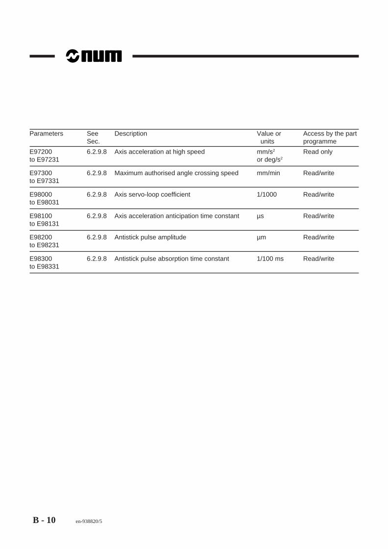
B - 10 en-938820/5
Parameters See Description Value or Access by the partSec. units programme
E97200 6.2.9.8 Axis acceleration at high speed mm/s2 Read onlyto E97231 or deg/s2
E97300 6.2.9.8 Maximum authorised angle crossing speed mm/min Read/writeto E97331
E98000 6.2.9.8 Axis servo-loop coefficient 1/1000 Read/writeto E98031
E98100 6.2.9.8 Axis acceleration anticipation time constant µs Read/writeto E98131
E98200 6.2.9.8 Antistick pulse amplitude µm Read/writeto E98231
E98300 6.2.9.8 Antistick pulse absorption time constant 1/100 ms Read/writeto E98331

Word Format Summary Table
en-938820/5 C - 1
C
Appendix C Word Format Summary Table
The formats of the axis words specified in the table are expressed as follows:- For linear axes: 5 digits to the left and 3 to the right of the decimal point are allowed
when the internal system unit (see Sec. 2.1) is µm- For rotary axes: 3 digits to the left and 4 to the right of the decimal point are allowed
when the internal system unit is 0.0001 degree.
For instance, for linear axes: if the system is set to 0.1 µm (internal unit), the formatsare expressed with 4 decimal digits; for the X axis, the format is X+044.
For instance, for rotary axes: if the system is set to 0.001 degree (internal unit), theformats are expressed with 3 decimal digits; for the C axis, the format is C+033.
For the words related to the machining feed rate with no assigned formats (F.., EF..),refer to the machine manufacturer’s manual for the maximum and minimum feedrates (maximum 8 digits and decimal point).
Format Description
%051 Programme number (1 to 99999.9)
N05 Sequence number (1 to 32767)
G02 Preparatory functions (0 to 99)G03 Preparatory functions (100 to 250 and 997 to 999)
H05 Subroutine number (with G77, G76 and G48)
X+053 Movement on the X axis. In a cycle, end point on the machining axis
Y+053 Movement on the Y axis
Z+053 Movement on the Z axis. In a cycle, end point on the machining axis
I+053 For circular interpolation (G02, G03), centre of the circleJ+053 With programmed origin offset (G59), centre of rotation of an angular offset (ED)K+053I+053 For roughing cycle (G64, G65), finishing machining allowance on XK+053 For roughing cycle (G64, G65), finishing machining allowance on ZK053 For rigid tapping cycle (G84), tap pitchK053 For thread cutting cycle (G33, G38), thread pitch
U+053 Movement on the U axis
V+053 Movement on the V axis
W+053 Movement on the W axis

C - 2 en-938820/5
Format Description
A+034 Movement on the A axis
B+034 Movement on the B axis
C+034 Movement on the C axisC+034 Spindle indexing modulo 360 degrees (M19)
E+/E- For profil geometry programming (PGP), tangent element
EA+033 For profile geometry programming (PGP), line angleEA+033 For thread cutting cycle (G33), apex half-angle of a tapered threadEA+033 For roughing cycle with groove (G63), start angle for pass settingEA+033 For groove roughing cycle (G65), groove pass setting angleEA+033 For plunging cycle (G66), groove bottom slope angleEA+033 In polar programming, angle of the line
EB+053 For contour definition and PGP, radius or fillet between two interpolationsEB-053 For contour definition and PGP, chamfer between two linear interpolationsEB+033 For thread cutting cycle (G33), tool penetration angleEB+033 For roughing cycle with groove (G63), limit groove penetration angle
EC+033 For roughing cycle with groove (G63), limit end of pass angle in roughing axis
ED+034 Programmed angular offset
EF.. For roughing cycle with groove (G63), penetration feed rate in materialEF. For grooving cycle (G65), penetration feed rate in materialEF.. In a reaming cycle (G85), retraction rateEF.. Feed rate specific to fillets (EB+) or chamfers (EB-)EF.. Maximum feed rate after an interrupt (G10)EF022 For plunging cycle (G66), dwell in groove bottomEF022 For cycles (G83, G87), dwell at the end of each penetration
EG03 For interpolation, acceleration modulation
EH+053 In (G81 to G89) cycles, dimension of the impact plane on the machining axis
EI+053 In polar programming, length of the line (start/circle centre)
EP053 In a peck drilling cycle (G83), backoff clearance after each peckEP053 In a drilling cycle with chip breaking (G87), backoff between two infeedsEP053 In a plunging cycle (G66), value of retraction at 45 degrees at the end of the pass
EQ053 For roughing cycle with groove (G63), minimum chip size
EK01 For rigid tapping cycle (G84), penetration/retraction speed ratio

Word Format Summary Table
en-938820/5 C - 3
C
Format Description
ER053 For roughing cycle with groove (G63), finishing allowanceER+053 In cycles (G81 to G89), dimension of the approach or retraction plane on the machining axis
ES+/ES- For profile geometry programming (PGP), secant elementES02 In cycles G83 and G87, number of infeeds at constant valueES02 In cycles (G33), number of passes at constant value
ET+/ET- For profile geometry programming (PGP), tangent element
EU+053 For roughing cycle with groove (G63), with XZ, pass setting angle and limit of last pass
EW+053 For roughing cycle with groove (G63), with XZ, pass setting angle and limit of last pass
EX+053 For roughing cycle with groove (G63), pass end position in XEX+053 In polar programming, angle of the line (start/end)
EZ+053 For roughing cycle with groove (G63), pass end position in Z
P053 For thread cutting cycle (G33), total depth of threadP053 For roughing cycle (G63, G64, G65), pass depth in XP053 For plunging cycle (G66), step in XP053 For cycles (G83 or G87), value of the first penetrationP041 For axis group synchronisation (G78), wait for markerP+ / P- Tool axis orientation (G16), along X or U
Q053 For thread cutting cycle (G33), depth of last passQ053 For roughing cycle (G63, G65), holding of positioning before pass settingQ053 For cycles (G83 or G87), value of the last penetrationQ04 For axis group synchronisation (G78), declaration of a marker
R+053 For circular interpolation (G02, G03), radius of the circleR053 For thread cutting cycle (G33), length of the retraction slope at the end of thread cuttingR053 For roughing cycle (G63, G64, G65), pass depth in ZR053 For plunging cycle (G66), step in ZR053 For tangential feed rate programming (G92), value of the curve radiusR+ / R- For linear interpolation (G00, G01), positioning at programmed distanceR+ / R- Tool axis orientation (G16), along Z (or W)
F.. Feed rate in mm/min and degrees/min (G94)F.. Feed rate in inches/min (G94)F.. Feed rate in mm/rev (G95)F.. Feed rate in inches/rev (G95)F022 Dwell in seconds (G04)F02 For thread cutting cycle (G33), number of threads (1 to 99)

C - 4 en-938820/5
Format Description
M02 Miscellaneous functions (0 to 99)M03 Miscellaneous functions (100 to 899)
NC04 Spline curve number (1-9999) with interpolation (with G48, G06, G49)
S05 Spindle rpm limiting (G92)S05 Constant surface speed in m/min (G96)S05 or S032 Spindle speed in rpm (G97)S02 In a subroutine branch (G77), number of subroutine iterations (1 to 99)S02 For thread cuttting cycle (G33), number of passes (1 to 99)
T08 Tool number (0 to 9999999)
D03 Correction number (0 to 255)
L03 Programme variables L (0 to 19, 100 to 199 and 900 to 959)
E5 External parameters E

List of Errors
en-938820/5 D - 1
D
Appendix D List of Errors
D.1 Miscellaneous Errors and Machine Errors D - 3
D.2 Parametric Programming Errors D - 5
D.3 Profile Geometry Programming (PGP) Errors D - 6D.3.1 The end point is not determined or cannot
be computed from the elements in theblocks D - 6
D.3.2 The point of tangency or intersectioncannot be computed from the data in twoblocks D - 6
D.3.3 The points of tangency or intersectioncannot be computed from the data in threeblocks D - 6
D.3.4 Fillet or chamfer definition errors D - 7D.3.5 Miscellaneous errors in PGP D - 7
D.4 Miscellaneous Errors D - 7
D.5 Request for Movements Outside the Machine Travel Limits D - 8
D.6 Structured Programming Errors D - 8
D.7 Axis Errors D - 8
D.8 Errors in Pocket Cycles D - 9
D.9 Axes Not Identified on the Bus D - 10
D.10 Dynamic Operators in C D - 10
D.11 Spline Curve Interpolation Errors D - 10
D.12 Errors in Numaform D - 11
D.13 Cycle Programming Errors D - 12

D - 2 en-938820/5

List of Errors
en-938820/5 D - 3
D
D.1 Miscellaneous Errors and Machine Errors
Error No. Meaning of the error1 Unknown character / Axis not recognised by the system
Too many digits after a functionPresence of a sign after a function which does not allow signsTruncated block signalled by ? via CLOSE in drip feed mode
2 Unknown G function or a mandatory argument missing after the G3 Attribute of a G code wrongly positioned4 Option not enabled or option parameter conflict:
Structured programming, RTCP, synchronised axes, etc.5 Geometric option programming not enabled6 Polynomial interpolation option missing coefficient table full7 Error in programming movements parallel to inclined axes (grinder):
- Programming is not in plane G20- Interpolation is not in G00 or G01- X is not programmed after G05- X and Z are not programmed after G07
8 Tool correction number too high9 A sequence of too many non-working blocks - Endless Loop10 In PLC terminal access: Bus exchange error11 In PLC terminal access: Bus initialisation error or exchange inhibited12 In PLC terminal access: Rack parameter error13 In PLC terminal access: No such card14 Inclined plane option missing
PLC boundary access: channel missing15 Invalid line configuration16 Error in RTCP activation17 End of block in a comment - close bracket missing18 ∗ Servo error: P50 too small20 No M02 at the end of the programme
Blocks not made executable in a cycle called by a G function21 Blank definition incoherent in 3D mode24 Error in inclined plane declaration
- Function reactivated when already active- Function argument declaration incomplete- Pivot point axis does not exist or is not servo-controlled- Incoherent value in one of the matrix terms
25 Subroutine or sequence number does not exist26 Too many subroutine nesting levels27 Radius offset: In G52 machine origin programming / With taper threads28 Syntax error in CCSPD or index table radius definition
G96 must be followed by S / G97 must be followed by S / initial radius cannot be determinedX or U not programmed in this block or a previous block
∗ Machine error. Caution: For this type of error, a CNC reset causes a general reset (CNC reset + PLC reset)

D - 4 en-938820/5
Error No. Meaning of the error29 No range programmed for CCSPD / No range compatible with S in G97:
No range search option: S not included between min. and max. values of the range programmedWith range search option: S does not belong to any range
30 Line error detected31 ∗ PPR or PPL mode impossible with the line protocol selected32 ∗ Homing error / Axis already on limit switch33 ∗ All slides on wait for synchronisation34 Minimum radius reached in G21 interpolation35 ∗ Sequence number not found in SEARCH36 ∗ Part programme memory full37 Max. feed rate exceeded for thread cutting (COMAND)38 Spindle already controlled by another axis group39 ∗ Axis synchronisation error (with axis synchronisation option)40-49 ∗ Excessive following error on axis 0 to 950-59 ∗ Excessive following error on axis 10 to 1960-69 ∗ Excessive following error on axis 20 to 2970 and 71 ∗ Excessive following error on axis 30 and 3172 Incremental programming after an incomplete block (PGP)75 Switch from state G20 to G21 or G22:
last block in G20 incomplete as it is programmed in PGP or radius correction or with X ≤ 0first block in G21 without X and Y or G22 without Y and ZSwitch from state G21 or G22 to G20: last block in G21 or G22 incomplete or first block in G20 inmode G41 or G42: In G21 or G22, initial radius negative or zero
76 In G21, programming of a fixed turning and milling cycle77 Tool type incompatible with the machining phase (milling or turning)78 Syntax error in programming slide synchronisation
G78 P: Maximum 4 digits, must be less than the number of slidesG78 Q: Maximum 4 digitsNo M00, M01 or M02 with G78 P..
∗ Machine error. Caution: For this type of error, a CNC reset causes a general reset (CNC reset + PLC reset).

List of Errors
en-938820/5 D - 5
D
D.2 Parametric Programming ErrorsError No. Meaning of the error91 Parameter No. not recognised92 Negative parameter assigned to a function which does not take a sign
Parameter value higher than the maximum value of the function to which it is assigned93 Error in parameter declaration or test expression:
L function not followed by symbols =,<,>, &, !Association with a prohibited function by a linking character -, +, *, /.
94 Operation prohibited in a parametric expression:Square root of a negative number / Division by 0
95 Attempt to write in an external input parameter or a read-only parameter96 The block preceding the external parameter declaration is incomplete
Programming of L100 ... in a contour definition in G6497 Parameter update impossible in G76:
No symbol = after the parameter numberLess than 10 characters allocated for entry of the value
98 Write by an axis group of a dynamic operation already used by another group99 Error related to the N/M AUTO function
- More than 5 N/M AUTO axes defined- Non-servo-controlled axis defined as N/M AUTO- Definition of an N/M AUTO axis of another group

D - 6 en-938820/5
D.3 Profile Geometry Programming (PGP) Errors
D.3.1 The end point is not determined or cannot be computed from the elements in theblocks
Error No. Meaning of the error101 PGP: Insufficient data for programming a circle
Circle programmed on two parallel axes (with R / see Error 107)102 Line programmed by an angle and one coordinate with no way of calculating the other coordinate106 In G02, G03, programming of the third axis without helical option107 PGP: Circle programmed by its radius and end point, with the end point separated from the start
point by more than 2 * radiusCircle programmed by X, Z, I K with a start radius different from the end point (20 microns) /Helical: dimension of 3rd axis missingCircle programmed on two parallel axes (with I, J, K / see Error 101)
D.3.2 The point of tangency or intersection cannot be computed from the data in twoblocks
Error No. Meaning of the error110 PGP: Syntax error in the first of two blocks of a PGP entity111 PGP: Syntax error in the second block of a PGP entity112 PGP: Line/line intersection in which:
First block starting point = second block end point, orFirst line angle = second line angle
113 PGP: The values programmed in the two blocks do not allow determination of an intersection ortangency point
114 PGP: Intersection or tangency point not determined by ET+, ET-, ES+ or ES-
D.3.3 The points of tangency or intersection cannot be computed from the data in threeblocks
Error No. Meaning of the error121 PGP: Syntax error in the last of the three blocks of a PGP entity122 PGP: The first two blocks are non-intersecting lines123 PGP: The data programmed in the three blocks do not allow determination of the tangent point124 PGP: Tangent point of the second and third blocks not specified by ET+ or ET-

List of Errors
en-938820/5 D - 7
D
D.3.4 Fillet or chamfer definition errors
Error No. Meaning of the error130 Zero displacement in one of the two blocks connected by a fillet or a chamfer131 Fillet or chamfer programmed in a block including M0, M1 or M2
Programming insufficient in a sequence of blocks, not allowing determination of the end point135 A chamfer can only connect two straight lines
D.3.5 Miscellaneous errors in PGP
Error No. Meaning of the error136 More than two blocks without movement between two geometric elements whose intersection or
tangency point is to be calculated137 Change of interpolation plane with an invalid block
D.4 Miscellaneous ErrorsError No. Meaning of the error138 Change of interpolation plane when not in G40 (FCU)139 Two carried parallel axes programmed in the same block outside G52 and outside G00140 Radius correction programming error:
Too many extraneous blocks between two consecutive pathsThe following functions cannot be programmed when radius offset is active: M00, M01, M02,access to external parameters, writing of parameters E8xxxx or L > 100
141 Carried parallel axes: Programming of a circle whose start point was programmed with one axisand whose end point was programmed with the associated parallel axis
143 Scale factor cancelled or enabled with radius offset144 Movement of a quantified axis different from the increment145 G29: ABS VAL (P * P + Q * Q + R * R - 1000 mm) > 1 mm (normal vector not a unit vector146 Offset in space / G29
- At least one of dimensions P, Q or R missing- At least one of dimensions X/U, Y/V or Z/W missing
148 Number of axes programmed exceeds the maximum authorised number149 Tool radius too large with respect to programmed path

D - 8 en-938820/5
D.5 Request for Movements Outside the Machine Travel LimitsError No. Meaning of the error150 Travel overrun on the X axis151 Travel overrun on the Y axis152 Travel overrun on the Z axis153 Travel overrun on the U axis154 Travel overrun on the V axis155 Travel overrun on the W axis156 Travel overrun on the A axis157 Travel overrun on the B axis158 Travel overrun on the C axis159 Request for programmed movement on an UN-HOMED axis
D.6 Structured Programming ErrorsError No. Meaning of the error190 Too many branch or loop nesting levels (maximum 15)191 Non-compliance with the syntax in structured programming
structured programming prohibited in MDI modethe index of a FOR loop must be: an L variable, a symbolic variable or a parameter E80000,E81000 or E82000non-compliance with the syntax of PUSH and PULL instructionsDO missing after WHILEprogramming of IF, THEN, ELSE in MDI mode
192 Keyword not recognised or prohibited in the context193 Structure error195 Programme stack saturated / Too many constants defined for the space allocated196 Error in array index declaration197 Use of a symbol not declared as VAR198 Syntax error in variable symbol declaration199 Incorrect variable declaration syntax
D.7 Axis ErrorsError No. Meaning of the error210 to 219 ∗ Poor signal or pulse generator complementarity error on axis 0 to 9220 to 229 ∗ Poor signal or pulse generator complementarity error on axis 10 to 19230 to 239 ∗ Poor signal or pulse generator complementarity error on axis 20 to 29240 and 241 ∗ Poor signal or pulse generator complementarity error on axis 30 and 31245 ∗ Fault on digital servo-control
∗ Machine error. Caution: For this type of error, a CNC reset causes a general reset (CNC reset + PLC reset)

List of Errors
en-938820/5 D - 9
D
D.8 Errors in Pocket Cycles
Error No. Meaning of the error260 Working memory busy261 Programme number too high262 NU number not among those authorised263 Execution impossible - Test or Graphic mode mandatory after first load or after editing264 No dimension programmed in the contouring plane or dimension outside the plane265 First positioning block missing; contour definition must begin with G0 or G1266 Not enough memory267 Character not allowed in pocket syntax268 Pocket programming block incomplete or containing illegal data269 Contour block incomplete / Positioning block missing before pocket definition270 Pocket definition partly or completely missing271 Tool orientation not perpendicular to the contouring plane272 Real tool not compatible with pocket technological data273 Change of contouring plane between pocket definition and machining274 Two nested pocket definitions275 NU0 programmed with G59276 Zero pocket depth277 Pocket definition start point or end point coordinates incomplete278 The spindle rotation direction is incompatible with the one required in the pocket definition279 G function not allowed in a pocket programming block280 First contour block incomplete281 Discontinuity in one of the contours described282 Pocket definition parameter error(s)283 The external contour must be unique and must exist284 Error in contour definition285 Too many contours286 Pass setting excessive with respect to the tool diameter287 Pass setting insufficient with respect to the dimensions288 Finishing infeed in an acute angle or an unroughed area: change the infeed point289 Tool diameter excessive290 Internal error291 Finishing infeed outside the contour292 Double positioning at the start of the contour293 Roughing end point present during facing

D - 10 en-938820/5
D.9 Axes Not Identified on the BusError No. Meaning of the error300 to 309 ∗ Axis 0 to 9 declared in P2 but not detected on the bus310 to 319 ∗ Axis 10 to 19 declared in P2 but not detected on the bus320 to 329 ∗ Axis 20 to 29 declared in P2 but not detected on the bus330 and 331 ∗ Axis 30 and 31 declared in P2 but not detected on the bus
∗ Machine error. Caution: For this type of error, a CNC reset causes a general reset (CNC reset + PLC reset)
D.10 Dynamic Operators in CError No. Meaning of the error400 Loading dyn. ops in C: The size of user code is too big401 Loading dyn. ops in C: Format error402 Loading dyn. ops in C: Checksum error403 The system has insufficient memory for dyn. ops in C404 Loading dyn. ops in C: Open error405 Loading dyn. ops in C: Read error406 Loading dyn. ops in C: Close error407 Loading dyn. ops in C:The directory is empty410 Dyn. ops in C: Number of parameters passed doesn’t tally411 Dyn. ops in C: USER ERROR from INIT: negative return413 Unrecognised dyn. ops in C414 Dyn. ops in C without MAIN420 Dyn. ops in C: USER ERROR from the QUIT function421 Dyn. ops in C: USER ERROR from the QUIT function: negative return423 Dyn. ops in C: Range of function in C not from [0..100]
D.11 Spline Curve Interpolation ErrorsError No. Meaning of the error600 Curve number zero601 N.. N.. must be programmed602 No axes programmed in the first block of the contour603 Curve slope undefined604 Less than three blocks in the profile605 Curve number unknown

List of Errors
en-938820/5 D - 11
D
D.12 Errors in NumaformError No. Meaning of the error700 Options missing701 S.. missing at beginning of curve702 Number of S.. different in T1 & T2703 Minimum 2 occurrences of S in T1704 Undefined section (in T3)705 Plane switching outside S mark706 Spindle stopped707 Invalid E= function708 E=1 or E=2: Section positioning error709 T1 & T2 can’t have any points in common710 P, Q must be positive711 S different in T1 & T2712 Undetermined tool position713 Error: S=0 or T>3730 F= less than or equal to zero731 Intersection of concentric circles732 Intersection of parallel lines733 Limit cannot be a horizontal plane740 F = error

D - 12 en-938820/5
D.13 Cycle Programming ErrorsError No. Meaning of the error830 Positioning not completed831 Spindle stopped832 End point, P and K must be programmed833 Retraction clearance too small834 EB value: -90 < EB < +90835 The values of P, Q, R and K are absolute values836 The interpolation plane must be G81 or G20837 Bad value of F or S862 P or R and end point to be programmed863 End point incoherent with EA864 Milling tool prohibited in G66871 Finished profile limits not defined872 No dimensions in blank definition873 P or R not programmed874 Blank inconsistent with finished profile875 No intersection of EA with the profile876 Relief angle EB incorrectly defined880 Cycle axis unknown881 Parameter value not compatible882 Hole bottom dimension not programmed883 Pitch (I J K) or clearance (P) not programmed884 More than 9 thread starts885 Pocket incompatible with the plane selected886 Tool incompatible with the radius programmed887 Cut > tool diameter888 Dwell prohibited in this cycle889 Syntax error890 Tool orientation incompatible891 Return plane = bottom of hole892 Axial feed missing893 Lateral feed missing894 ER prohibited in G20895 G21,G22 prohibited in cycle896 Dimension incompatible with tool radius897 Length of oblong pocket < diameter898 Tool corrector missing899 Spindle not assigned to this group or spindle or group incompatible

Index
en-938820/5 I - 1
Index
Symbols! 6-5, 6-18$ 4-288$0 4-288% 2-9& 6-5, 6-18* 6-4, 6-18+ 6-4, 6-18- 6-4, 6-18/ 4-256, 6-4, 6-18< 6-6, 6-19> = 6-6, 6-19< > 6-6, 6-19= 6-6, 6-19> 6-6, 6-19> = 6-6, 6-19[*BGxx] 6-61[*BMxx] 6-61[*Rxx] 6-62
AA 6-5, 6-18Absolute encoder 6-41Access symbols 6-60Access to Profil 5-22Accurate stop at the end of a block 4-59Addition 6-4, 6-18Address equivalences 6-54Addresses
with assigned values 5-5without assigned values 5-7
Addressingof 8I8O analogue card analogue inputs 6-27of 8I8O analogue card analogue outputs 6-27of G functions 6-61of M functions 6-61of the deceleration function 6-22of the PLC input terminals 6-27of the PLC output terminals 6-27of the turret type 6-22
Affaire No 6-26Amplitude
of the antistick pulse on reversal 6-45Angle crossing 6-22, 6-44Angle crossing speed analysis angle 6-23Angle element of a line 5-5Angular offset 4-215, 6-22Answer to a message sent 4-291Arc tangent 6-5, 6-18Arguments 2-19
programmed alone 2-20Arithmethic functions 6-5, 6-18Arithmetic operations 6-4, 6-18
Assigninga slave axis to a master axis 6-39a variable to a CNC function 6-7an external parameter to a CNC function 6-46axes 6-32variables 6-3
Associating a slave (or driven) axis with a master (or drive) axis 6-42Automatic control function exchange parameters 6-20Automatic deletion of variables 7-13Automatic homing subroutine 4-193, 4-275Automatic homing subroutine branch 4-193, 4-275Available parameters 6-30Axes programmable with reference to diameter 4-284Axes programmed on diameter 6-34Axis
acceleration anticipation time constant 6-44acceleration at high speed 6-44acceleration at the work rate 6-44clamp 4-246clamp enable status 6-40coupling 6-34declared rotary modulo 360 degrees 6-41duplicated in “automatic” modes 6-42duplicated in manual mode (Jog) 6-42group synchronisation 4-279measurement 6-39measurement correction 6-41position reference 6-32programming 3-1programming by variable L or parameter E defined by a
symbolic variable 7-8reference memory 6-32reference offset 6-41retraction 4-127servo or non-servo status 6-39servo-contro coefficient 6-44unclamp 4-246
Axis (or spindle) in-position window 6-41Axis/spindle switching 6-42
BBackoff between two infeeds 4-127Basic cycles 4-91Bevel gear 4-73Block 2-7
data access symbols 6-60deletion by G76- 4-202execution enable 4-264format 2-7insertion by G76+ 4-200processing 4-264sequencing without stopping movement 4-185skip 4-256
Blocking message 4-291Boolean values 6-61

I - 2 en-938820/5
Boring 4-117, 4-127cycle with indexed spindle stop in hole bottom 4-122cycles 4-101stop in hole bottom 4-127with dwell 4-122
BS 2-10
CC 6-5, 6-18Call on reset 4-194, 4-275Call to subroutine return block 4-196Calling
a contour by function G77 5-23a contour created by Profil 5-23a contour from a machining cycle 5-24
Cancellation of MDI and EDIT modes 4-247Canned cycle 4-91
cancel 4-91Canned cycles 4-128Cartesian coordinates 4-229Centre drilling 4-104, 4-127Centre drilling cycle 4-104Chamfer
between two intersecting lines 5-6between two linear interpolations 4-58programming 4-57, 5-17
Change of direction 6-23Characteristics of ISO and EIA codes 2-13Characters used in EIA code 2-16Characters used in ISO code 2-15Circular interpolation 4-36Circular interpolation defined by three points 4-44Clearance after peck 4-127Clockwise circular interpolation 4-36Clockwise spindle rotation 4-11CNC 2-3CNC processor 1-7Codes C0 to C8 1-13Combined encoder 6-41Common CNC parameters 6-37Comparison for conditional branch 6-65Comparison symbols 6-6, 6-19Complete circle 6-22Conditional jump 6-47, 6-65Constant pitch thread cutting 4-92Constant pitch thread cutting cycle 4-92Constant surface speed 4-15, 4-17Contour by Profil 5-23Control of direction of rotation 4-11Control of spindles 1 to 4 4-23Control system 2-3Conversion of the internal unit 6-6, 6-19Coolant 4-247Coolant off 4-247Coordinate system 1-5
with C axis 4-226
Coordinatesof the centre of a circle 5-5of the end point of a circle 5-5of the end point of a line 5-5
Correction of slave axes with respect to master axes 6-37Cosine 6-5, 6-18Counter boring 4-106, 4-127Counter boring cycle 4-106Counterclockwise circular interpolation 4-36Counterclockwise spindle rotation 4-11Creating error messages 8-3Creation of a programme 2-3Current axis group number 6-25Current mode number 6-25Current speed on programmed path 6-28Current spindle release in axis group 4-278Current tool axis orientation 6-29Current tool correction number 6-29Cycles G81 to G89 4-127Cylindrical coordinates 4-234
DD.. 4-74DAT1 1-9, 6-30, 4-206DAT2 1-9, 6-30, 4-206Datum shift DAT1 and DAT2 enable 4-206Datum shift DAT1 and DAT2 inhibit 4-206Deceleration function on several blocks 6-22Declaration of a variable in the programme 6-8Decoded M functions 2-22Definition
of a circle by its arc angle 4-53of a spline curve 4-211of an entity 5-4of geometric elements 5-3of offsets 1-9of the addresses characterising the PGP 5-5of tool dimensions 1-12of tool tip radius and orientation 1-13of travels and origins 1-7
DELETE 7-13Deletion of a spline curve 4-216, 4-225Deletion of symbolic variables in the stack 7-13Different from 6-6, 6-19Direction of axis movement during interpolation 6-32Discriminant 5-7Displaying
a message with wait for an answer 6-56messages with a parametric value 6-58
Distance remaining to be travelled in the block 6-28Division 6-4, 6-18Drilling cycle with chip breaking 4-119Drilling cycles 4-101Drilling with chip breaking 4-119, 4-127Dripfeed mode 4-195Dwell 4-127, 4-238Dwell on each infeed 4-127

Index
en-938820/5 I - 3
DX 1-14Dynamic correction on X 6-29Dynamic correction on Z 6-29Dynamic tool correction 1-14Dynamic tool correction definition 1-14DZ 1-14
EE+/E- 5-7EA.. 5-5EB+ 4-57EB+.. 5-6EB- 4-58EB-.. 5-6ED.. 4-215EDIT 4-252EDIT mode 4-252Editing programmes 4-286EG.. 4-258EIA programme structure 2-10Emergency retraction 4-189Emergency retraction on a PLC axis group 4-285Enable 4-259Encoded M functions 2-22Encoder type 6-41End
of EIA programme 2-10of ISO programme 2-9of programme load 2-9of retraction 4-127of symbolic variable declaration 7-7
ENDV 7-7EOR 2-10Equal to 6-6, 6-19Equivalence of variables 6-14Error messages 8-3Error numbers 8-3ES 5-7ET 5-7, 6-5, 6-18Examples of use of external parameters E 6-48Exchanging axes between groups 4-286Exchanging spindles between groups 4-287External parameter declaration 6-46External parameter E programming syntax 6-44External parameters E 6-16
FFeed rate
in degrees per minute 4-61in inches per minute 4-61in inches per revolution 4-64in millimetres per minute 4-61in millimetres per revolution 4-64limiting after interrupt 4-184specific to chamfers EB- 4-68specific to fillets EB+ 4-68
Filletbetween two interpolations 4-57between two intersecting elements 5-6programming 4-57, 5-17
Flashing message 4-289Forced block concatenation 4-264Forced block sequencing 4-254Front thread cutting 4-98Front turret 3-8
GG functions
incompatible with the programme state 2-18with associated arguments 2-19
General diagrams of parametric programming 6-64General information on modes 1-3General information on the system 1-3General programme structure 2-8Geometric elements 5-3, 5-9Gradual acceleration 6-22Graphic machining simulation status 6-26Greater than 6-6, 6-19Greater than or equal to 6-6, 6-19Groove roughing 4-140Groove roughing cycle 4-140Group axis access parameters 6-31Group turret type 6-22
HHigh precision contouring 6-24High speed 4-29Homing 1-7
direction 6-41on an axis 6-40status without switch wiring 6-41without switch wiring 6-41
II.. K.. 5-5Image of operand EN.20 6-25Image of system job reference 6-26Inch data input 4-239
inclined axis 4-267inclined axis state 4-267
Inclined on a grinder 6-31inclined wheel 4-267inclined wheel state 4-267
Inclined wheel on a grinder 6-31Incremental encoder 6-41Independent spindle 4-276Index 4-279Infeed at work rate 4-127Initial X value definition 4-228Instruction 2-4Instructions 1-3Internal measurement units 2-4, 3-3Internal system unit 6-6, 6-19

I - 4 en-938820/5
Interpolation block execution time 6-23Interpolation speed limiting 6-35Interrupt handling 4-182Interruptible block 4-181ISO and EIA codes and standards 2-3, 2-8, 2-12ISO functions 2-12ISO programme
structure 2-9tape 2-14tape format 2-14
ISO programming 4-1
JJump to a sequence without return 4-175
LL../E.. 6-57Left radius correction 4-79Less than 6-6, 6-19Less than or equal to 6-6, 6-19Limit switches 1-7Linear interpolation 4-32
at high speed 4-29at the programmed feed rate 4-32
Linear X, Y and Z axes 1-5List of
external parameters E 6-20variables L 6-3
Loading of a parametric expression 6-64Logical operations 6-5, 6-18Loop time constant 6-26
MM functions 2-21M post-functions 2-21M pre-functions 2-21M.. 4-172Machine 1-5
description 1-6origin (Om) 1-7
Machine status 6-25access parameters 6-25
Main programme 2-11Mandatory arguments 2-19Marker 4-279Master axis position reference 6-37Maximum authorised speed at angle crossings 6-44Maximum axis speed 6-44Maximum dynamic machine travel 6-30Maximum spindle x indexing speed 6-36Maximum static machine travel 6-32MDI 4-252MDI mode 4-252Measured axis 6-41
Measurementdimensions 1-11origin 1-7origin (OM) 1-7origin offset 1-8origin setting 1-7
Meeting point 4-281Message acknowledgements 4-291Messages 4-288Minimum dynamic machine travel 6-30Minimum static machine travel 6-32Mirror function 4-261, 6-21Mirror function processing 6-21Miscellaneous M functions 2-21Mixed programming 4-6Modal G functions 2-18Modal M functions 2-21Modes 1-3Movement origin selection 4-203Movement origins 4-203Multiple axis groups 4-273Multiple start thread cutting 4-96Multiplication 6-4, 6-18
NN 4-14Nonblocking message 4-291Nonmodal G functions 2-18Nonmodal M functions 2-21Notes on EIA code 2-17Notes on ISO code 2-17Number
of CNC axis groups 6-26of constant infeeds 4-127of machine axis groups 6-26programming 8-1
Numerical values 6-62
OOffsets 1-8
on the X axis (solution with DAT2) 1-10on the X axis (solution without DAT2) 1-10on the Z axis 1-9
OM 1-7Om 1-7On-the-fly measurement (hardware interrupt) 4-182OP 1-9Op 1-9Operation number 6-24Operations executable with external parameters E 6-18Operations executable with variables L 6-4Optional arguments 2-19Optional stop 4-250OR 6-5, 6-18Origin switch
enable state 6-40status 6-41

Index
en-938820/5 I - 5
ORPOM 1-8Other functions 4-238Overspeed
by handwheel 4-242coefficient on the path in G12 6-23
PParallel carrier/carried axes 3-5Parametric expression 6-64Parametric geometric transformations 6-30Parametric programming 6-1, 6-64Part
contour 5-3origin 1-9origin offset 1-9programme 2-3
Path sequencing 4-59Paths 4-59Peck drilling 4-108, 4-127Peck drilling cycle 4-108PGP 5-3PGP geometric entity 5-4PGP programming 5-18PLC axes 4-278Plunging 4-146Plunging cycle 4-146Polar angle 4-46Polar angle reference axis 4-46Polar coordinates 4-226Polar programming 4-46
in incremental dimensions 4-5of a circle 4-49of a line 4-47
Position of origin switch 6-41Positioning with stop at programmed distance 4-31, 4-35Preparatory G functions 2-18Preselecting the programme origin 4-207Primary X, Y and Z axes 1-6PROFIL 5-22PROFIL function 5-22Profile geometry programming 5-1Programme 1-3, 2-1, 2-9
analysis 6-22analysis access parameters 6-21backup 4-283backup media 1-3creation by G76+ 4-198declaration 4-268, 4-278definition 1-3delection by G76- 4-199dimensions 1-11load by peripheral 2-12numbering 2-12origin 1-9origin offset 1-9, 4-209, 6-21stack 7-1, 7-3start 2-9, 2-10
status access symbols 6-60structure 2-1variables L 6-3
Programmed acceleration override 4-258Programmed cancellation
of edit (EDIT) mode 4-252of manual data input (MDI) mode 4-252of subroutine calls by the machine processor 4-252
Programmed deletion of variables 7-13Programmed feed stop 4-240Programmed G and M function processing 4-264Programmed offset 6-30Programmed stop 4-248Programming
a circle by its radius 4-38in absolute dimensions 4-5in absolute dimensions with respect to the measurement
origin 4-203in absolute dimensions with respect to the programmeorigin 4-5in cartesian coordinates 4-229in cylindrical coordinates 4-234in inches or metric units 4-244in incremental dimensions relative to the block start point 4-5in metric units 4-244in polar coordinates 4-226of a meeting point 4-281of A, B or C axes declared as non-rotary 3-7of cycles 4-124of entirely defined geometric elements 5-9of error messages 8-1of geometric elements 5-9of geometric elements not entirely defined 5-10of independent secondary axes 3-4of movements 4-32of movements in absolute dimensions with respect to
the measurement origin 4-198of parallel carrier/carried axis pairs 3-5of PLC axes 4-285of rotary axes modulo 360 degrees 3-6of servoed rotary axes with limited excursion 3-7of the tool centre 6-22of variables L 6-11with reference to diameter 4-9, 6-22with reference to radius 4-9
Programming examplesin PGP 5-18of variables L 6-11
Programming notes on variables L 6-14Programming of the discriminant
with intersecting elements 5-8with tangent elements 5-8
Programming system 4-5PULL 7-5PULL function 7-5PUSH function 7-4

I - 6 en-938820/5
RR 1-13, 6-5, 6-18R.. 5-6Radius of a circle 5-6Radius offset cancel 4-80Rapid positioning 4-29
before machining 4-30Rapid retraction after machining 4-30Reactivation
of edit modes 4-252of manual data input modes 4-252of subroutine calls 4-252
Reaming cycle 4-117Rear turret 3-8Restoring the values of variables L 7-5Restoring variables L 7-4Restrictions due to drip feed mode 4-195Retraction after penetration 4-127Review 1-1
of axis orientation 1-5of definitions 1-5of machine 1-5
Right radius correction 4-79Rigid tapping 4-113Rigid tapping cycle 4-113Rotary A, B and C axes 1-5Rough facing 4-131, 4-157Rough turning 4-131, 4-157Rough turning/facing cycle 4-128Roughing 4-128Roughing cycle with groove 4-151Roughing with groove 4-151Ruler with encoded reference marks 6-41
SS 6-5, 6-18Sagittal error 6-24Sampling period 6-26Saving in the stack 7-4Saving variables L 7-4Scaling factor 4-259, 6-31
enable 4-259inhibit 4-259
Secant element 5-7Secondary linear U, V and W axes 1-6Sending a message
to a peripheral 4-290to a remote server 4-290to the display 4-288to the PLC function 4-290
Sending messages 4-288Sequence 2-7
branches in the programme 4-168breaks 4-165interrupt 4-181
Sequenced thread cutting 4-99
Sequences 4-165Servo-control error tolerated on a circle 6-23Servoed rotary axes with limited excursion 3-7Setting of the feed rate potentiometer 6-28Sine 6-5, 6-18Software switches 1-8Special programming of multiple axis groups 4-273Special programming of PLC axes 4-283Special use of sequence interrupt 4-185Speed of movement 4-61Speed demand for the spindle controlled by its group 6-36Speed threshold below which spindle x is considered stopped 6-38Spindle 4-11, 4-20, 4-23, 4-127
access parameters 6-34and feed rate potentiometer enable 4-255and feed rate potentiometer inhibiting 4-255control 4-11control selection 4-23controlled by an axis group 4-277indexing 4-21measurement 4-25measurement selection 4-25position reference 6-36potentiometer 6-22programming 4-277rotation speed (N) 4-14, 4-16speed 4-13, 4-27speed control 4-13speed limiting 4-17, 4-27speed range 4-20speed setting 6-36stop 4-11synchronisation 4-293
Spindle xacceleration with indexing 6-37in-position window 6-37indexing gain 6-37position reference 6-36speed setting 6-36
Spline 4-216Spline curve 4-216, 4-217
definition 4-217execution command 4-216
Spline interpolation 4-216Square root 6-5, 6-18Stack allocation 7-3Start
of EIA programme 2-10of ISO programme 2-9
Subroutine branchby automatic control function 4-178by M function 4-172execution 4-178with multiple axis groups 4-275
Subroutine branches 2-11Subroutine display inhibited 2-12Subroutine nesting levels 4-169Subroutine on reset 4-194, 4-275

Index
en-938820/5 I - 7
Subroutine return block 4-196Subroutine structure 4-179Subroutines 2-11Subroutines with multiple axis groups 4-275Subtraction 6-4, 6-18Surface speed (V) 4-14, 4-17Suspension of execution 4-264Symbolic addressing of variables L 6-15Symbolic variable declaration 7-7Symbolic variables 7-1, 7-7Symbolic variables in ISO programming 7-9Symbols addressing Boolean values 6-61Symbols addressing numerical values 6-62Symmetrically driven axis 6-43Synchronised axis 6-43System 1-3
TT 6-5T function 4-269Table summarising cycles 4-127Tangent element 5-7Tangential feed rate 4-66Tapered thread cutting 4-96Tapping 4-111, 4-127Tapping clearance 4-114Tapping cycle 4-111Tapping cycles 4-101Temporary suspension of next block preparation 4-187Test
on a variable for a conditional jump 6-10on an external parameter for a conditional jump 6-48
Thread cuttingby penetration to thread flank 4-95by straight penetration 4-95with retraction slope 4-95without retraction slope 4-95
Time constant to absorb the antistick pulse 6-45Tolerance interval coefficient 6-38Tool
axis 4-72axis orientation 4-72call 4-70corrections 4-74, 4-75cutting part radius 1-13inside the profile 4-84outside the profile 4-83position 4-81position with respect to the part 4-79programming 4-70radius R 6-29radius R correction 4-76retraction 4-85retraction slope 4-95type 6-30
Tool correction 6-29call 4-74
Tool dimensionsin x 6-29in z 6-29
Tool tip 4-78orientation 1-13, 4-78, 6-29orientation code 1-13
Tools 4-70Transferring
the current values of parameters 6-55the current values of variables L 6-55
Travels 1-7Truncating 6-5Turn/face roughing cycle 4-128
UUnconditional branch to a sequence of blocks with return 4-165Unconditional subroutine branch 4-165Use of the stack 7-3
VV 4-14VAR 7-7VAR and ENDV functions 7-7VAR H.. N.. N.. 7-11VAR H.. N.. N.. function 7-11Variable acquisition in the stack 7-11Variable L programming syntax 6-7Variables L 7-1
WWord 2-4
defining a dimension 2-6format 2-4not defining a function 2-6
Writing a programme 1-4Writing of a block defining
a path 2-8a tool change 2-7the start of spindle rotation 2-8
XXOFF 2-9

I - 8 en-938820/5