Hardware Descriptive Languages these notes are taken from Mano’s book
Hardware Design with VHDL VHDL Introduction ECE 443
ECE UNM 1 (8/19/15)
Programming Languages (PL) vs. Hardware Description Languages (HDL)
Programming languages such as C or Java cannot serve as HDLs (unless modified
significantly).
Programming languages are modeled after a sequential process, where operations are
performed in a sequential order (order matters).
This is amenable to the human thinking process, in which an algorithm is
unfolded into a recipe or step-by-step process
HDLs such as VHDL (VHSIC (Very High Speed Integrated Circuit) HDL) and Ver-
ilog were developed to support the underlying characteristics of hardware
• Connections of parts
• Concurrent operations
• Concept of propagation delay and timing
These characteristics cannot be captured by traditional PLs
Hardware Design with VHDL VHDL Introduction ECE 443
ECE UNM 2 (8/19/15)
Hardware Description Languages (HDL)
HDLs serve several roles in the design process
• Formal documentation
• Input to a simulator
• Input to a synthesizer
The fundamental characteristics of a digital circuit are captured using the concepts:
• Entity: a self-contained, basic building block of a real circuit
• Connectivity: models the connecting wires among the circuit components
• Concurrency: models parallel operations carried out by interconnected components
• Timing: models starting and ending of each operation and defines an order
HDLs can be used to describe a design at the gate level and RT level, in either a
structural or behavioral view.
Other highlights of a modern HDL include:
• Sequential execution constructs (similar to PLs) for modeling behavior
• A set of mathematical, Boolean and other special purpose operations, e.g., shifting
• Constructs to support hierarchical design process
Hardware Design with VHDL VHDL Introduction ECE 443
ECE UNM 3 (8/19/15)
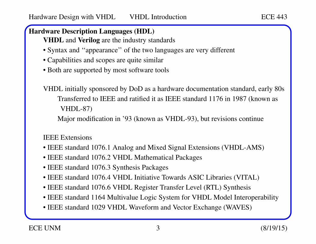
Hardware Description Languages (HDL)
VHDL and Verilog are the industry standards
• Syntax and ‘‘appearance’’ of the two languages are very different
• Capabilities and scopes are quite similar
• Both are supported by most software tools
VHDL initially sponsored by DoD as a hardware documentation standard, early 80s
Transferred to IEEE and ratified it as IEEE standard 1176 in 1987 (known as
VHDL-87)
Major modification in ’93 (known as VHDL-93), but revisions continue
IEEE Extensions
• IEEE standard 1076.1 Analog and Mixed Signal Extensions (VHDL-AMS)
• IEEE standard 1076.2 VHDL Mathematical Packages
• IEEE standard 1076.3 Synthesis Packages
• IEEE standard 1076.4 VHDL Initiative Towards ASIC Libraries (VITAL)
• IEEE standard 1076.6 VHDL Register Transfer Level (RTL) Synthesis
• IEEE standard 1164 Multivalue Logic System for VHDL Model Interoperability
• IEEE standard 1029 VHDL Waveform and Vector Exchange (WAVES)
Hardware Design with VHDL VHDL Introduction ECE 443
ECE UNM 4 (8/19/15)
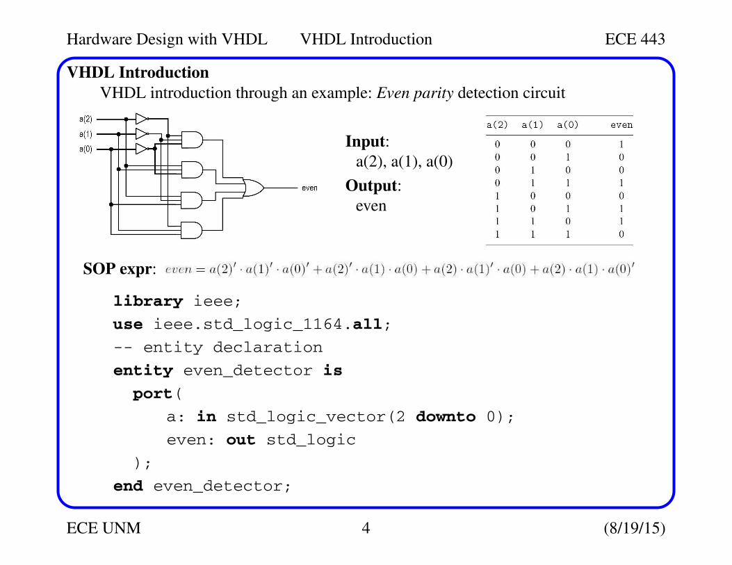
VHDL Introduction
VHDL introduction through an example: Even parity detection circuit
library ieee;
use ieee.std_logic_1164.all;
-- entity declaration
entity even_detector is
port(
a: in std_logic_vector(2 downto 0);
even: out std_logic
);
end even_detector;
Input:
a(2), a(1), a(0)
Output:
even
SOP expr:
Hardware Design with VHDL VHDL Introduction ECE 443
ECE UNM 5 (8/19/15)
VHDL Introduction
-- architecture body
architecture sop_arch of even_detector is
signal p1, p2, p3, p4 : std_logic;
begin
even <= (p1 or p2) or (p3 or p4);
p1 <= (not a(2)) and (not a(1)) and (not a(0));
p2 <= (not a(2)) and a(1) and a(0);
p3 <= a(2) and (not a(1)) and a(0);
p4 <= a(2) and a(1) and (not a(0));
end sop_arch;
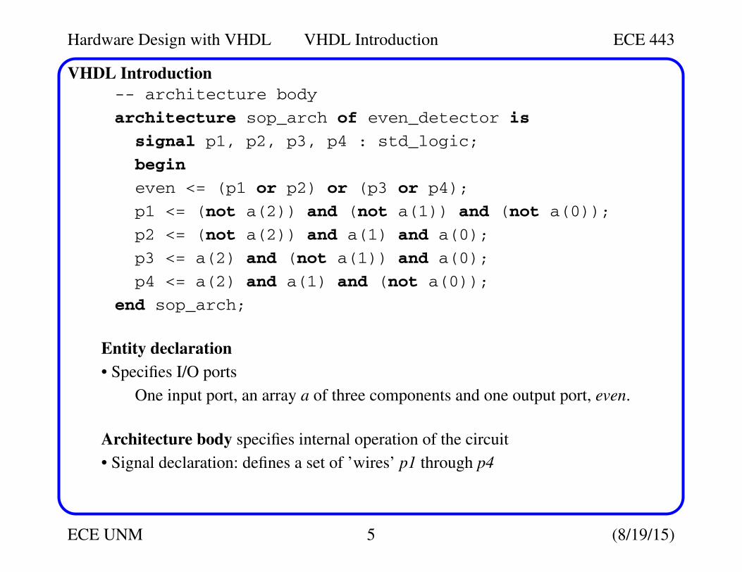
Entity declaration
• Specifies I/O ports
One input port, an array a of three components and one output port, even.
Architecture body specifies internal operation of the circuit
• Signal declaration: defines a set of ’wires’ p1 through p4
Hardware Design with VHDL VHDL Introduction ECE 443
ECE UNM 6 (8/19/15)
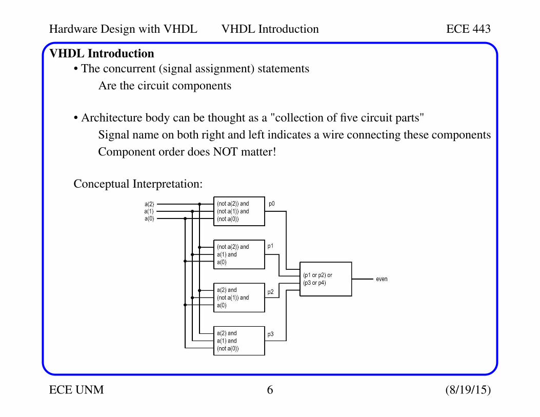
VHDL Introduction
• The concurrent (signal assignment) statements
Are the circuit components
• Architecture body can be thought as a "collection of five circuit parts"
Signal name on both right and left indicates a wire connecting these components
Component order does NOT matter!
Conceptual Interpretation:

Hardware Design with VHDL VHDL Introduction ECE 443
ECE UNM 7 (8/19/15)
VHDL Introduction
More efficient architecture which uses xor operator (entity declaration is the same):
architecture xor_arch of even_detector is
signal odd: std_logic;
begin
even <= not odd;
odd <= a(2) xor a(1) xor a(0);
end xor_arch;
Structural Description
In structural view, a circuit is constructed of smaller components
A structural description specifies the types of parts and connections
Essentially a textual description of a schematic
Hardware Design with VHDL VHDL Introduction ECE 443
ECE UNM 8 (8/19/15)
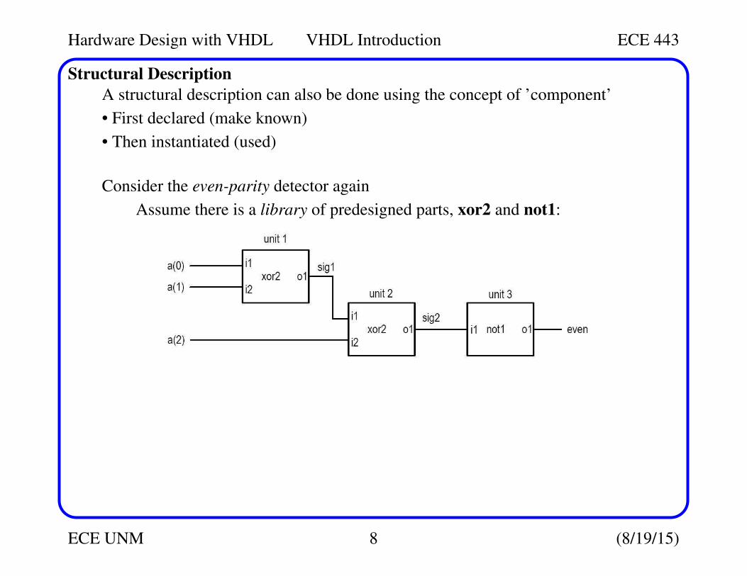
Structural Description
A structural description can also be done using the concept of ’component’
• First declared (make known)
• Then instantiated (used)
Consider the even-parity detector again
Assume there is a library of predesigned parts, xor2 and not1:
Hardware Design with VHDL VHDL Introduction ECE 443
ECE UNM 9 (8/19/15)
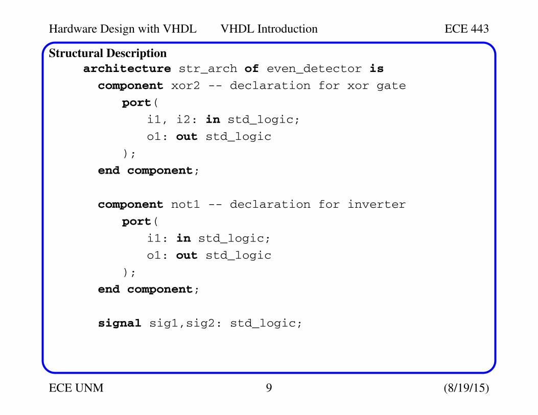
Structural Description
architecture str_arch of even_detector is
component xor2 -- declaration for xor gate
port(
i1, i2: in std_logic;
o1: out std_logic
);
end component;
component not1 -- declaration for inverter
port(
i1: in std_logic;
o1: out std_logic
);
end component;
signal sig1,sig2: std_logic;
Hardware Design with VHDL VHDL Introduction ECE 443
ECE UNM 10 (8/19/15)
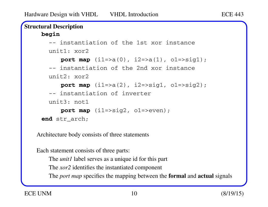
Structural Description
begin
-- instantiation of the 1st xor instance
unit1: xor2
port map (i1=>a(0), i2=>a(1), o1=>sig1);
-- instantiation of the 2nd xor instance
unit2: xor2
port map (i1=>a(2), i2=>sig1, o1=>sig2);
-- instantiation of inverter
unit3: not1
port map (i1=>sig2, o1=>even);
end str_arch;
Architecture body consists of three statements
Each statement consists of three parts:
The unit1 label serves as a unique id for this part
The xor2 identifies the instantiated component
The port map specifies the mapping between the formal and actual signals
Hardware Design with VHDL VHDL Introduction ECE 443
ECE UNM 11 (8/19/15)
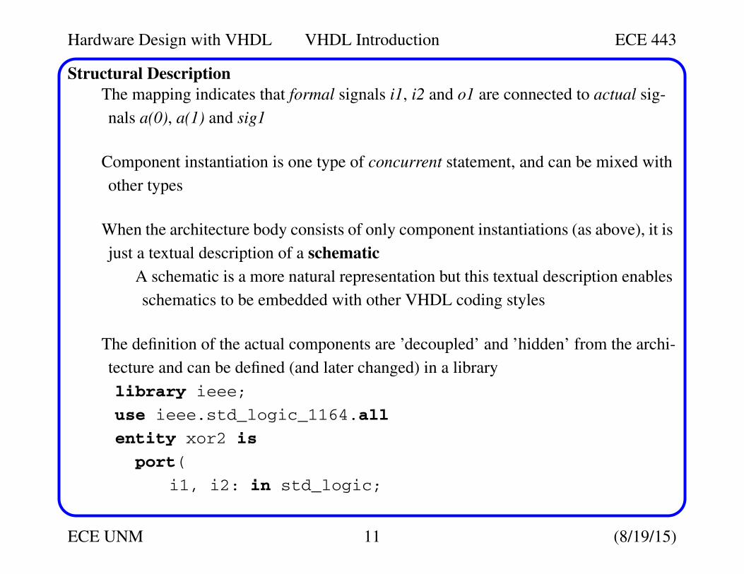
Structural Description
The mapping indicates that formal signals i1, i2 and o1 are connected to actual sig-
nals a(0), a(1) and sig1
Component instantiation is one type of concurrent statement, and can be mixed with
other types
When the architecture body consists of only component instantiations (as above), it is
just a textual description of a schematic
A schematic is a more natural representation but this textual description enables
schematics to be embedded with other VHDL coding styles
The definition of the actual components are ’decoupled’ and ’hidden’ from the archi-
tecture and can be defined (and later changed) in a library
library ieee;
use ieee.std_logic_1164.all
entity xor2 is
port(
i1, i2: in std_logic;
Hardware Design with VHDL VHDL Introduction ECE 443
ECE UNM 12 (8/19/15)
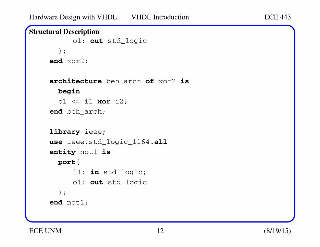
Structural Description
o1: out std_logic
);
end xor2;
architecture beh_arch of xor2 is
begin
o1 <= i1 xor i2;
end beh_arch;
library ieee;
use ieee.std_logic_1164.all
entity not1 is
port(
i1: in std_logic;
o1: out std_logic
);
end not1;
Hardware Design with VHDL VHDL Introduction ECE 443
ECE UNM 13 (8/19/15)
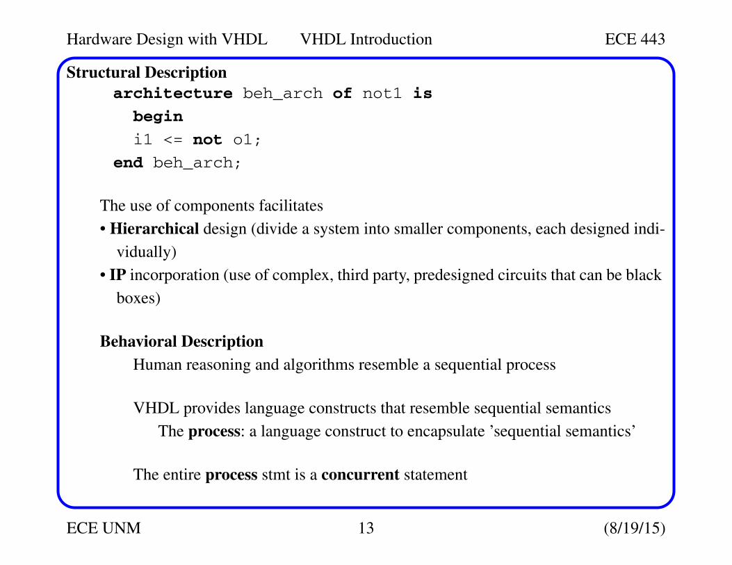
Structural Description
architecture beh_arch of not1 is
begin
i1 <= not o1;
end beh_arch;
The use of components facilitates
• Hierarchical design (divide a system into smaller components, each designed indi-
vidually)
• IP incorporation (use of complex, third party, predesigned circuits that can be black
boxes)
Behavioral Description
Human reasoning and algorithms resemble a sequential process
VHDL provides language constructs that resemble sequential semantics
The process: a language construct to encapsulate ’sequential semantics’
The entire process stmt is a concurrent statement
Hardware Design with VHDL VHDL Introduction ECE 443
ECE UNM 14 (8/19/15)
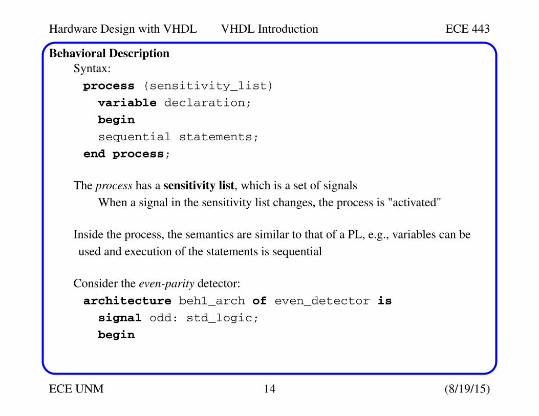
Behavioral Description
Syntax:
process (sensitivity_list)
variable declaration;
begin
sequential statements;
end process;
The process has a sensitivity list, which is a set of signals
When a signal in the sensitivity list changes, the process is "activated"
Inside the process, the semantics are similar to that of a PL, e.g., variables can be
used and execution of the statements is sequential
Consider the even-parity detector:
architecture beh1_arch of even_detector is
signal odd: std_logic;
begin
Hardware Design with VHDL VHDL Introduction ECE 443
ECE UNM 15 (8/19/15)
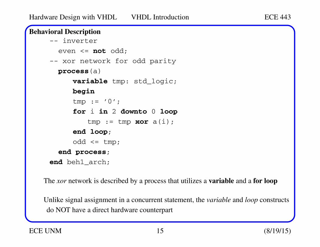
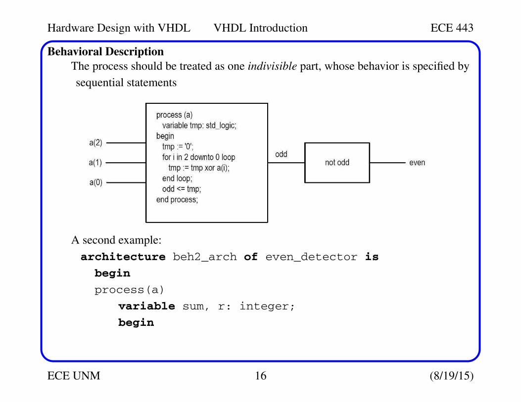
Behavioral Description
-- inverter
even <= not odd;
-- xor network for odd parity
process(a)
variable tmp: std_logic;
begin
tmp := ’0’;
for i in 2 downto 0 loop
tmp := tmp xor a(i);
end loop;
odd <= tmp;
end process;
end beh1_arch;
The xor network is described by a process that utilizes a variable and a for loop
Unlike signal assignment in a concurrent statement, the variable and loop constructs
do NOT have a direct hardware counterpart
Hardware Design with VHDL VHDL Introduction ECE 443
ECE UNM 16 (8/19/15)
Behavioral Description
The process should be treated as one indivisible part, whose behavior is specified by
sequential statements
A second example:
architecture beh2_arch of even_detector is
begin
process(a)
variable sum, r: integer;
begin
Hardware Design with VHDL VHDL Introduction ECE 443
ECE UNM 17 (8/19/15)
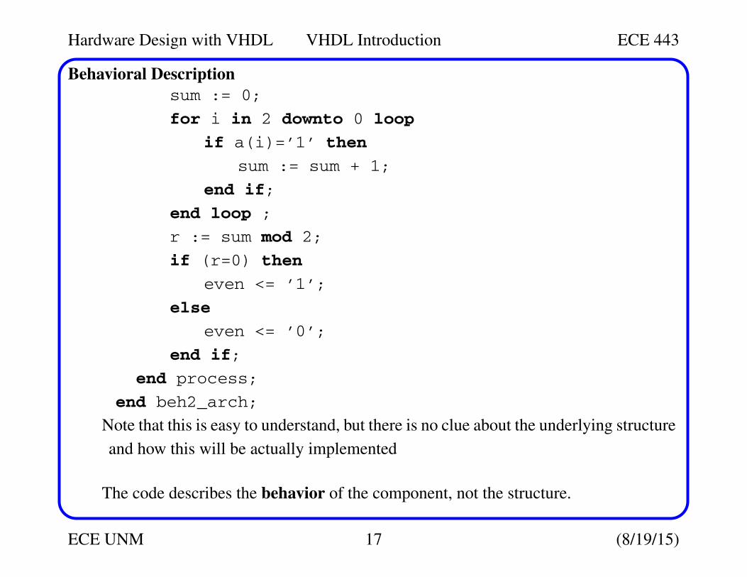
Behavioral Description
sum := 0;
for i in 2 downto 0 loop
if a(i)=’1’ then
sum := sum + 1;
end if;
end loop ;
r := sum mod 2;
if (r=0) then
even <= ’1’;
else
even <= ’0’;
end if;
end process;
end beh2_arch;
Note that this is easy to understand, but there is no clue about the underlying structure
and how this will be actually implemented
The code describes the behavior of the component, not the structure.
Hardware Design with VHDL VHDL Introduction ECE 443
ECE UNM 18 (8/19/15)
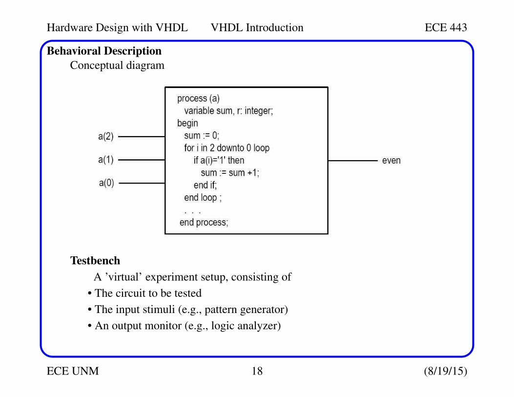
Behavioral Description
Conceptual diagram
Testbench
A ’virtual’ experiment setup, consisting of
• The circuit to be tested
• The input stimuli (e.g., pattern generator)
• An output monitor (e.g., logic analyzer)
Hardware Design with VHDL VHDL Introduction ECE 443
ECE UNM 19 (8/19/15)
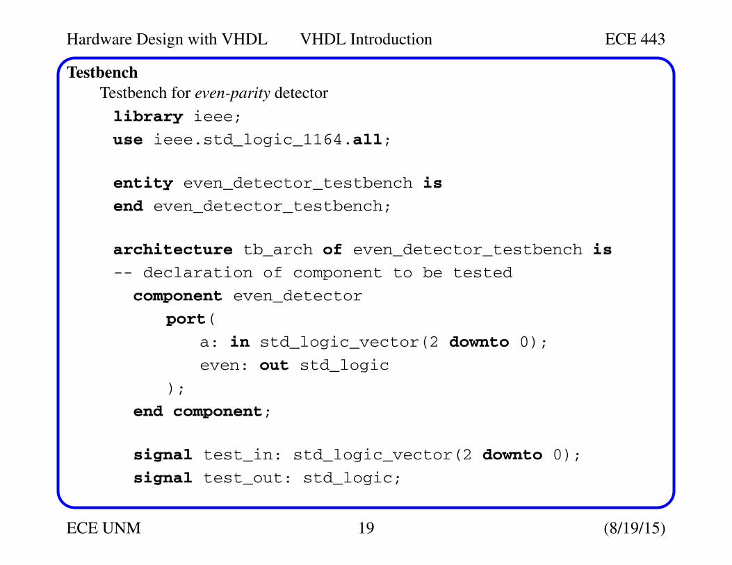
Testbench
Testbench for even-parity detector
library ieee;
use ieee.std_logic_1164.all;
entity even_detector_testbench is
end even_detector_testbench;
architecture tb_arch of even_detector_testbench is
-- declaration of component to be tested
component even_detector
port(
a: in std_logic_vector(2 downto 0);
even: out std_logic
);
end component;
signal test_in: std_logic_vector(2 downto 0);
signal test_out: std_logic;
Hardware Design with VHDL VHDL Introduction ECE 443
ECE UNM 20 (8/19/15)
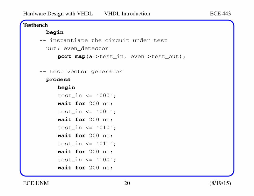
Testbench
begin
-- instantiate the circuit under test
uut: even_detector
port map(a=>test_in, even=>test_out);
-- test vector generator
process
begin
test_in <= "000";
wait for 200 ns;
test_in <= "001";
wait for 200 ns;
test_in <= "010";
wait for 200 ns;
test_in <= "011";
wait for 200 ns;
test_in <= "100";
wait for 200 ns;
Hardware Design with VHDL VHDL Introduction ECE 443
ECE UNM 21 (8/19/15)
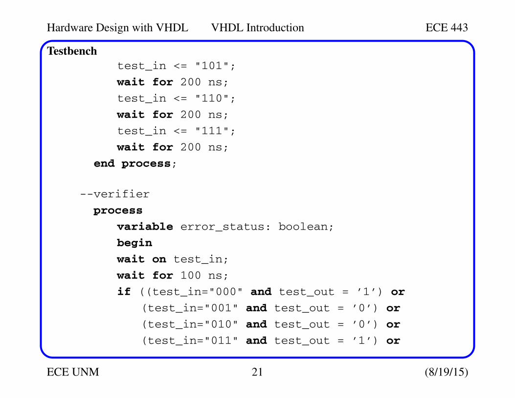
Testbench
test_in <= "101";
wait for 200 ns;
test_in <= "110";
wait for 200 ns;
test_in <= "111";
wait for 200 ns;
end process;
--verifier
process
variable error_status: boolean;
begin
wait on test_in;
wait for 100 ns;
if ((test_in="000" and test_out = ’1’) or
(test_in="001" and test_out = ’0’) or
(test_in="010" and test_out = ’0’) or
(test_in="011" and test_out = ’1’) or
Hardware Design with VHDL VHDL Introduction ECE 443
ECE UNM 22 (8/19/15)
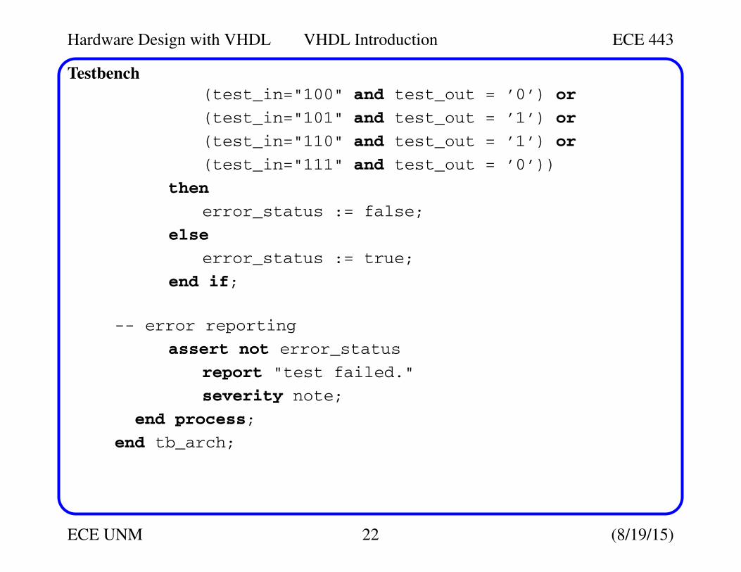
Testbench
(test_in="100" and test_out = ’0’) or
(test_in="101" and test_out = ’1’) or
(test_in="110" and test_out = ’1’) or
(test_in="111" and test_out = ’0’))
then
error_status := false;
else
error_status := true;
end if;
-- error reporting
assert not error_status
report "test failed."
severity note;
end process;
end tb_arch;
Hardware Design with VHDL VHDL Introduction ECE 443
ECE UNM 23 (8/19/15)
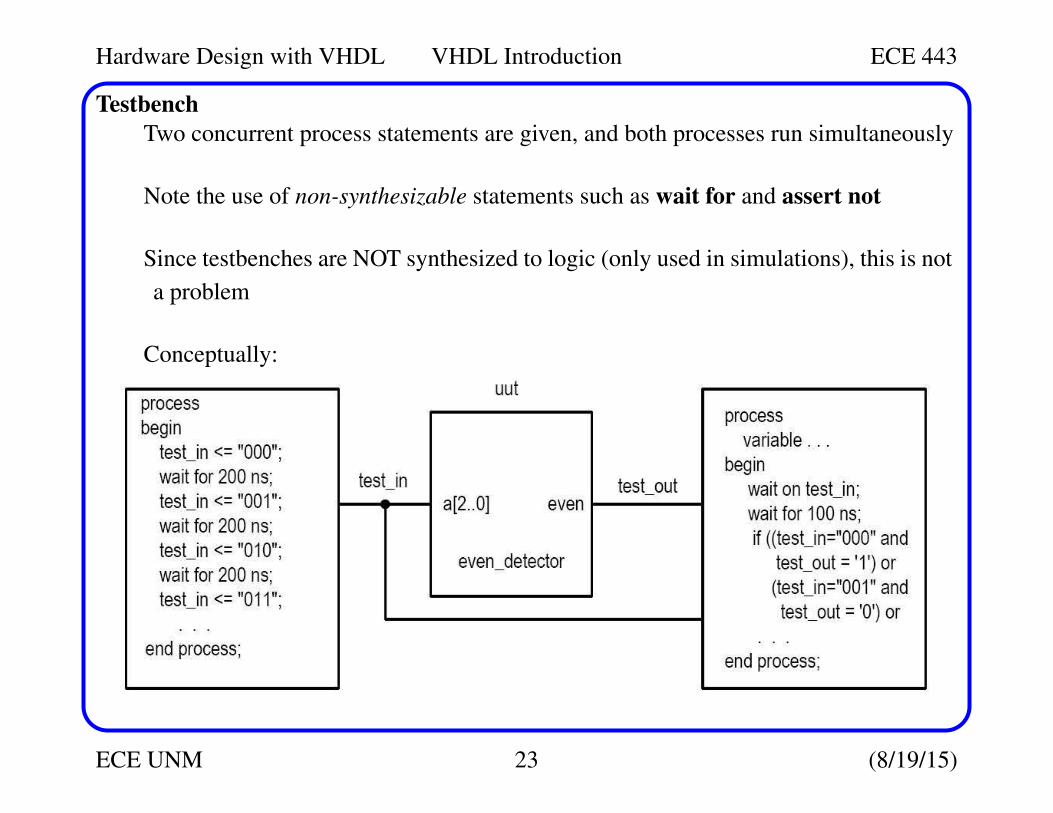
Testbench
Two concurrent process statements are given, and both processes run simultaneously
Note the use of non-synthesizable statements such as wait for and assert not
Since testbenches are NOT synthesized to logic (only used in simulations), this is not
a problem
Conceptually:
Hardware Design with VHDL VHDL Introduction ECE 443
ECE UNM 24 (8/19/15)
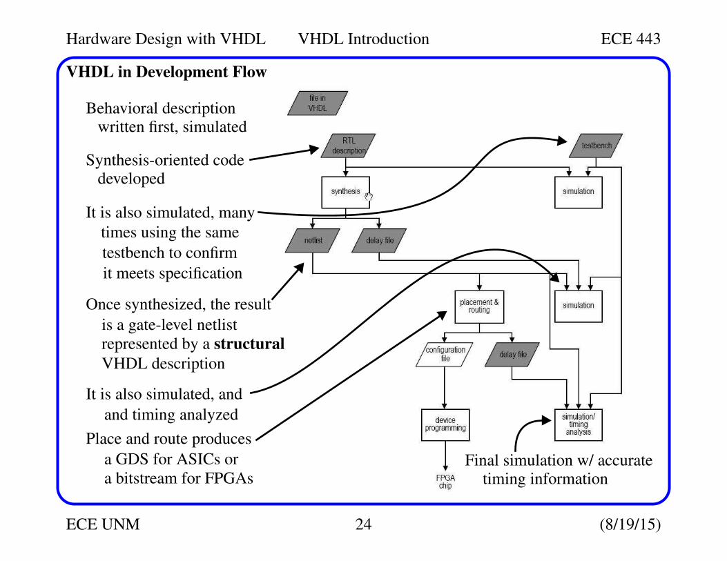
VHDL in Development Flow
Behavioral descriptionwritten first, simulated
Synthesis-oriented codedeveloped
It is also simulated, many
times using the same
testbench to confirm
it meets specification
Once synthesized, the result
is a gate-level netlist
represented by a structural
VHDL description
It is also simulated, and
and timing analyzed
Place and route produces
a GDS for ASICs or
a bitstream for FPGAsFinal simulation w/ accurate
timing information
Hardware Design with VHDL VHDL Introduction ECE 443
ECE UNM 25 (8/19/15)
Coding for Synthesis
Execution of VHDL code
• For Simulation:
Design is ’realized’ in a virtual environment, the simulation software
All language constructs can be ’realized’ here
• For Synthesis
Design is ’realized’ by hardware components
• Many VHDL constructs can NOT be synthesized, e,g, file operation, floating-
point data type, division
• Also realize that although any VHDL code is ’easy’ to simulate, it may be diffi-
cult to synthesize
VHDL code that contains 10 additions needs to be mapped to 10 adders
(unless resources are shared), a fairly complex set of hardware components