Programmable MC-4 Ignition Control
12
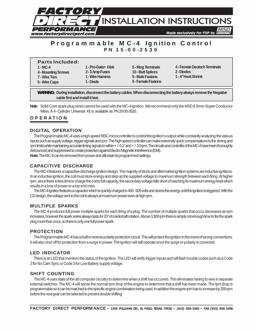
OPERATION DIGITAL OPERATION The Programmable MC-4 uses a high speed RISC microcontroller to control the ignition’s output while constantly analyzing the various inputs such as supply voltage, trigger signals and rpm. The high speed controller can make extremely quick compensations to the timing and rpm limits while maintaining accurate timing signals to within +/- 0.1° and +/- 10 rpm. The circuits and controller of the MC-4 have been thoroughly debounced and suppressed to create protection against Electro Magnetic Interference (EMI). Note: The MC-4 can be removed from power and still retain its programmed settings. CAPACITIVE DISCHARGE The MC-4 features a capacitive discharge ignition design. The majority of stock and aftermarket ignition systems are inductive ignitions. In an inductive ignition, the coil must store energy and step up the supplied voltage to maximum strength between each firing. At higher rpm, since there is less time to charge the coil to full capacity, the secondary voltage falls short of reaching its maximum energy level which results in a loss of power or a top end miss. The MC-4 Ignition features a capacitor which is quickly charged to 490 - 505 volts and stores this energy until the ignition is triggered. With the CD design, the voltage sent to the coil is always at maximum power even at high rpm. MULTIPLE SPARKS The MC-4 produces full power multiple sparks for each firing of a plug. The number of multiple sparks that occur decreases as rpm increases, however the spark series always lasts for 20° of crankshaft rotation. Above 3,300 rpm there is simply not enough time to fire the spark plug more than once, so there is only one full power spark. PROTECTION The Programmable MC-4 has a built in reverse polarity protection circuit. This will protect the ignition in the event of wrong connections. It will also shut off for protection from a surge in power. The ignition will still operate once the surge or polarity is corrected. LED INDICATOR There is an LED that monitors the status of the Ignition. The LED will verify trigger inputs and will flash trouble codes such as a Code 2 for No Cam Sync or Code 3 for Low Battery supply voltage. SHIFT COUNTING The MC-4 uses state of the art computer circuitry to determine when a shift has occurred. This eliminates having to wire in separate external switches. The MC-4 will sense the normal rpm drop of the engine to determine that a shift has been made. The rpm drop is programmable so it can be matched to the specific engine combination being used. In addition the engine rpm has to increase by 200 rpm before the next gear can be selected to prevent double shifting. Programmable MC-4 Ignition Control PN 15-00-2530 Parts Included: 1 - MC-4 4 - Mounting Screws 7 - Wire Ties 5 - Wire Caps WARNING: WARNING: WARNING: WARNING: WARNING: During installation, disconnect the battery cables. When disconnecting the battery always remove the Negative cable first and install it last. Note: Solid Core spark plug wires cannot be used with the MC-4 Ignition. We recommend only the MSD 8.5mm Super Conductor Wires. A 4 - Cylinder Universal Kit is available as PN 20-00-3520. 1 - Pro-Data+ Disk 2 - 3 Amp Fuses 1 - Wire Harness 1 - Diode FACTORY DIRECT PERFORMANCE • 1355 PULLMAN DR., EL PASO, TEXAS 79936 • (915) 858-3365 • FAX (915) 858-3496 5 - Ring Terminals 10 - Butt Splices 5 - Male Fastons 5 - Female Fastons 4 - Female Deutsch Terminals 2 - Diodes 1 - 4" Heat Shrink
Transcript of Programmable MC-4 Ignition Control
OPERATION
DIGITAL OPERATIONThe Programmable MC-4 uses a high speed RISC microcontroller to control the ignition’s output while constantly analyzing the various
inputs such as supply voltage, trigger signals and rpm. The high speed controller can make extremely quick compensations to the timing andrpm limits while maintaining accurate timing signals to within +/- 0.1° and +/- 10 rpm. The circuits and controller of the MC-4 have been thoroughlydebounced and suppressed to create protection against Electro Magnetic Interference (EMI).Note: The MC-4 can be removed from power and still retain its programmed settings.
CAPACITIVE DISCHARGEThe MC-4 features a capacitive discharge ignition design. The majority of stock and aftermarket ignition systems are inductive ignitions.
In an inductive ignition, the coil must store energy and step up the supplied voltage to maximum strength between each firing. At higherrpm, since there is less time to charge the coil to full capacity, the secondary voltage falls short of reaching its maximum energy level whichresults in a loss of power or a top end miss.
The MC-4 Ignition features a capacitor which is quickly charged to 490 - 505 volts and stores this energy until the ignition is triggered. With theCD design, the voltage sent to the coil is always at maximum power even at high rpm.
MULTIPLE SPARKSThe MC-4 produces full power multiple sparks for each firing of a plug. The number of multiple sparks that occur decreases as rpm
increases, however the spark series always lasts for 20° of crankshaft rotation. Above 3,300 rpm there is simply not enough time to fire the sparkplug more than once, so there is only one full power spark.
PROTECTIONThe Programmable MC-4 has a built in reverse polarity protection circuit. This will protect the ignition in the event of wrong connections.
It will also shut off for protection from a surge in power. The ignition will still operate once the surge or polarity is corrected.
LED INDICATORThere is an LED that monitors the status of the Ignition. The LED will verify trigger inputs and will flash trouble codes such as a Code
2 for No Cam Sync or Code 3 for Low Battery supply voltage.
SHIFT COUNTINGThe MC-4 uses state of the art computer circuitry to determine when a shift has occurred. This eliminates having to wire in separate
external switches. The MC-4 will sense the normal rpm drop of the engine to determine that a shift has been made. The rpm drop isprogrammable so it can be matched to the specific engine combination being used. In addition the engine rpm has to increase by 200 rpmbefore the next gear can be selected to prevent double shifting.
Programmable MC-4 Ignition ControlPN 15-00-2530
Parts Included:1 - MC-44 - Mounting Screws7 - Wire Ties5 - Wire Caps
WARNING:WARNING:WARNING:WARNING:WARNING: During installation, disconnect the battery cables. When disconnecting the battery always remove the Negativecable first and install it last.
Note: Solid Core spark plug wires cannot be used with the MC-4 Ignition. We recommend only the MSD 8.5mm Super ConductorWires. A 4 - Cylinder Universal Kit is available as PN 20-00-3520.
1 - Pro-Data+ Disk2 - 3 Amp Fuses1 - Wire Harness1 - Diode
FACTORY DIRECT PERFORMANCE • 1355 PULLMAN DR., EL PASO, TEXAS 79936 • (915) 858-3365 • FAX (915) 858-3496
5 - Ring Terminals10 - Butt Splices5 - Male Fastons5 - Female Fastons
4 - Female Deutsch Terminals2 - Diodes1 - 4" Heat Shrink
2 INSTALLATION INSTRUCTIONS
AUTOTRONIC CONTROLS CORPORATION • 1490 HENRY BRENNAN DR., EL PASO, TEXAS 79936 • (915) 857-5200 • FAX (915) 857-3344
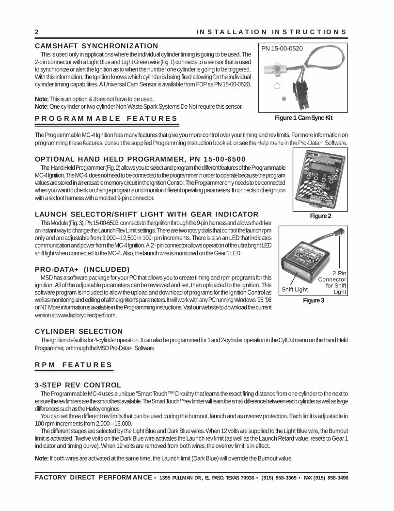
CAMSHAFT SYNCHRONIZATIONThis is used only in applications where the individual cylinder timing is going to be used. The
2-pin connector with a Light Blue and Light Green wire (Fig. 1) connects to a sensor that is usedto synchronize or alert the Ignition as to when the number one cylinder is going to be triggered.With this information, the Ignition knows which cylinder is being fired allowing for the individualcylinder timing capabilities. A Universal Cam Sensor is available from FDP as PN 15-00-0520.
Note: This is an option & does not have to be used.Note: One cylinder or two cylinder Non Waste Spark Systems Do Not require this sensor.
The Programmable MC-4 Ignition has many features that give you more control over your timing and rev limits. For more information onprogramming these features, consult the supplied Programming Instruction booklet, or see the Help menu in the Pro-Data+ Software.
OPTIONAL HAND HELD PROGRAMMER, PN 15-00-6500The Hand Held Programmer (Fig. 2) allows you to select and program the different features of the Programmable
MC-4 Ignition. The MC-4 does not need to be connected to the programmer in order to operate because the programvalues are stored in an erasable memory circuit in the Ignition Control. The Programmer only needs to be connectedwhen you want to check or change programs or to monitor different operating parameters. It connects to the Ignitionwith a six foot harness with a molded 9-pin connector.
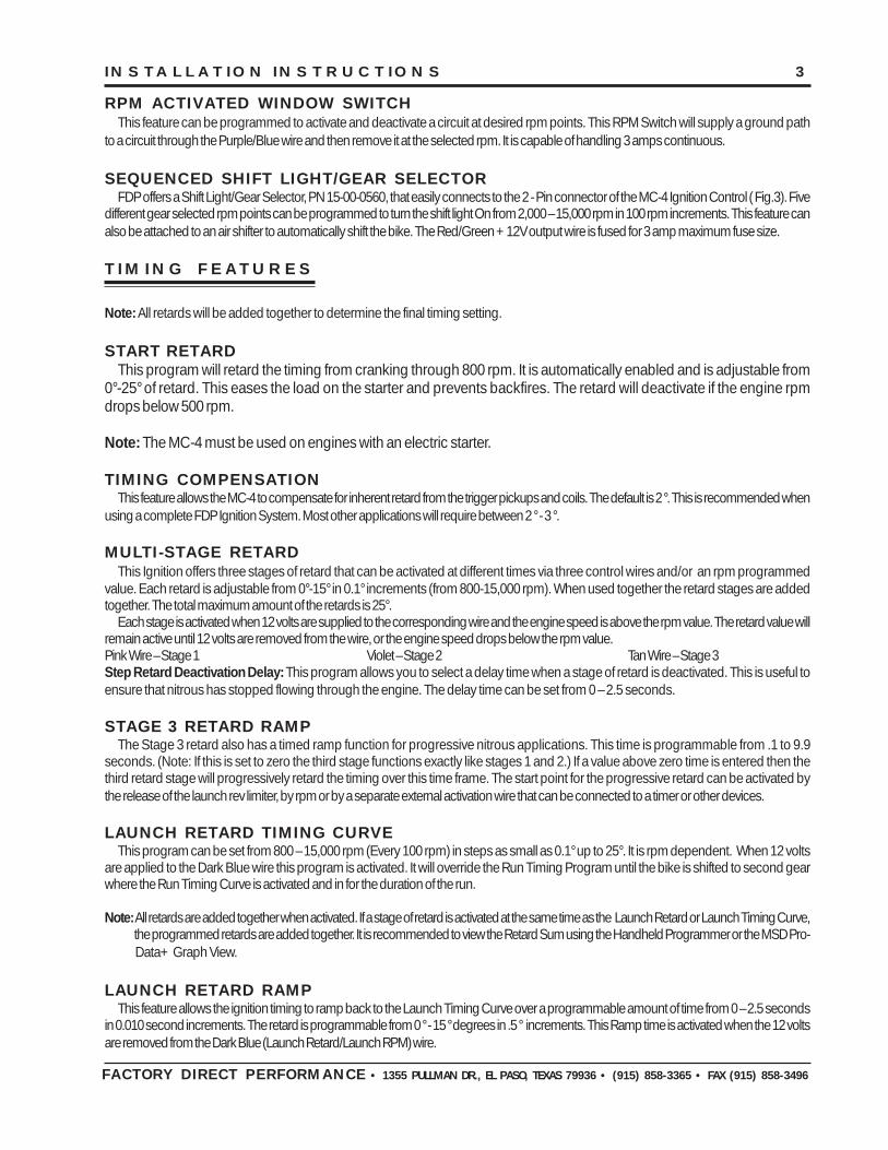
LAUNCH SELECTOR/SHIFT LIGHT WITH GEAR INDICATORThis Module (Fig. 3), PN 15-00-6503, connects to the Ignition through the 9-pin harness and allows the driver
an instant way to change the Launch Rev Limit settings. There are two rotary dials that control the launch rpmonly and are adjustable from 3,000 – 12,500 in 100 rpm increments. There is also an LED that indicatescommunication and power from the MC-4 Ignition. A 2 - pin connector allows operation of the ultra bright LEDshift light when connected to the MC-4. Also, the launch wire is monitored on the Gear 1 LED.
PRO-DATA+ (INCLUDED)MSD has a software package for your PC that allows you to create timing and rpm programs for this
ignition. All of the adjustable parameters can be reviewed and set, then uploaded to the ignition. Thissoftware program is included to allow the upload and download of programs for the Ignition Control aswell as monitoring and editing of all the ignition's parameters. It will work with any PC running Windows ’95, '98or NT. More information is available in the Programming instructions. Visit our website to download the currentversion at www.factorydirectperf.com.
CYLINDER SELECTIONThe Ignition default is for 4-cylinder operation. It can also be programmed for 1 and 2-cylinder operation in the CylCnt menu on the Hand Held
Programmer, or through the MSD Pro-Data+ Software.
RPM FEATURES
3-STEP REV CONTROLThe Programmable MC-4 uses a unique "Smart Touch™" Circuitry that learns the exact firing distance from one cylinder to the next to
ensure the rev limiters are the smoothest available. The Smart Touch™ rev limiter will learn the small difference between each cylinder as well as largedifferences such as the Harley engines.
You can set three different rev limits that can be used during the burnout, launch and as overrev protection. Each limit is adjustable in100 rpm increments from 2,000 – 15,000.
The different stages are selected by the Light Blue and Dark Blue wires. When 12 volts are supplied to the Light Blue wire, the Burnoutlimit is activated. Twelve volts on the Dark Blue wire activates the Launch rev limit (as well as the Launch Retard value, resets to Gear 1indicator and timing curve). When 12 volts are removed from both wires, the overrev limit is in effect.
Note: If both wires are activated at the same time, the Launch limit (Dark Blue) will override the Burnout value.
FACTORY DIRECT PERFORMANCE • 1355 PULLMAN DR., EL PASO, TEXAS 79936 • (915) 858-3365 • FAX (915) 858-3496
Figure 2
PROGRAMMABLE FEATURES
Figure 3
2 PinConnector
for ShiftLightShift Light
Figure 1 Cam Sync Kit
PN 15-00-0520
INSTALLATION INSTRUCTIONS 3
AUTOTRONIC CONTROLS CORPORATION • 1490 HENRY BRENNAN DR., EL PASO, TEXAS 79936 • (915) 857-5200 • FAX (915) 857-3344
RPM ACTIVATED WINDOW SWITCHThis feature can be programmed to activate and deactivate a circuit at desired rpm points. This RPM Switch will supply a ground path
to a circuit through the Purple/Blue wire and then remove it at the selected rpm. It is capable of handling 3 amps continuous.
SEQUENCED SHIFT LIGHT/GEAR SELECTORFDP offers a Shift Light/Gear Selector, PN 15-00-0560, that easily connects to the 2 - Pin connector of the MC-4 Ignition Control ( Fig.3). Five
different gear selected rpm points can be programmed to turn the shift light On from 2,000 – 15,000 rpm in 100 rpm increments. This feature canalso be attached to an air shifter to automatically shift the bike. The Red/Green +12V output wire is fused for 3 amp maximum fuse size.
TIMING FEATURES
Note: All retards will be added together to determine the final timing setting.
START RETARDThis program will retard the timing from cranking through 800 rpm. It is automatically enabled and is adjustable from
0°-25° of retard. This eases the load on the starter and prevents backfires. The retard will deactivate if the engine rpmdrops below 500 rpm.
Note: The MC-4 must be used on engines with an electric starter.
TIMING COMPENSATIONThis feature allows the MC-4 to compensate for inherent retard from the trigger pickups and coils. The default is 2 °. This is recommended when
using a complete FDP Ignition System. Most other applications will require between 2 ° - 3 °.
MULTI-STAGE RETARDThis Ignition offers three stages of retard that can be activated at different times via three control wires and/or an rpm programmed
value. Each retard is adjustable from 0°-15° in 0.1° increments (from 800-15,000 rpm). When used together the retard stages are addedtogether. The total maximum amount of the retards is 25°.
Each stage is activated when 12 volts are supplied to the corresponding wire and the engine speed is above the rpm value. The retard value willremain active until 12 volts are removed from the wire, or the engine speed drops below the rpm value.Pink Wire – Stage 1 Violet – Stage 2 Tan Wire – Stage 3Step Retard Deactivation Delay: This program allows you to select a delay time when a stage of retard is deactivated. This is useful toensure that nitrous has stopped flowing through the engine. The delay time can be set from 0 – 2.5 seconds.
STAGE 3 RETARD RAMPThe Stage 3 retard also has a timed ramp function for progressive nitrous applications. This time is programmable from .1 to 9.9
seconds. (Note: If this is set to zero the third stage functions exactly like stages 1 and 2.) If a value above zero time is entered then thethird retard stage will progressively retard the timing over this time frame. The start point for the progressive retard can be activated bythe release of the launch rev limiter, by rpm or by a separate external activation wire that can be connected to a timer or other devices.
LAUNCH RETARD TIMING CURVEThis program can be set from 800 – 15,000 rpm (Every 100 rpm) in steps as small as 0.1° up to 25°. It is rpm dependent. When 12 volts
are applied to the Dark Blue wire this program is activated. It will override the Run Timing Program until the bike is shifted to second gearwhere the Run Timing Curve is activated and in for the duration of the run.
Note: All retards are added together when activated. If a stage of retard is activated at the same time as the Launch Retard or Launch Timing Curve, the programmed retards are added together. It is recommended to view the Retard Sum using the Handheld Programmer or the MSD Pro- Data+ Graph View.
LAUNCH RETARD RAMPThis feature allows the ignition timing to ramp back to the Launch Timing Curve over a programmable amount of time from 0 – 2.5 seconds
in 0.010 second increments. The retard is programmable from 0 ° - 15 ° degrees in .5 ° increments. This Ramp time is activated when the 12 voltsare removed from the Dark Blue (Launch Retard/Launch RPM) wire.
FACTORY DIRECT PERFORMANCE • 1355 PULLMAN DR., EL PASO, TEXAS 79936 • (915) 858-3365 • FAX (915) 858-3496

4 INSTALLATION INSTRUCTIONS
AUTOTRONIC CONTROLS CORPORATION • 1490 HENRY BRENNAN DR., EL PASO, TEXAS 79936 • (915) 857-5200 • FAX (915) 857-3344
GEAR RETARDSThis feature allows you to program a different retard for each gear without any extra wiring. Once the shift sequence is reset with the
Launch Control Wire ( Dark Blue ), the MC-4 will retard the timing automatically following each shift. Zero to 5° can be removed in each gear andthe retards are cumulative, (example: 3° in 3rd, 3° in 4th and 4° in 5th, total 10°). The Launch Control Retard Curve allows 1st gear timing and 2ndgear uses the Run Retard Curve. Each additional shift can be programmed to have additional retards without the use of external switches.
RUN TIMING CURVEThis is the program for the full ignition timing curve from 800 – 15,000 rpm. The curve is adjustable in 0.1° increments every 100 rpm
with 25° maximum. The Run Timing Curve is the default program and remains active at all times unless the Launch Timing Curve isactivated at which point it is overridden until the first shift when the Launch Timing Curve is deactivated.
Note: The Run Timing Curve will be added to any Stage Retards and Gear Retards that are activated throughout the run. Maximumretard using the Run Curve is 25°.
INDIVIDUAL CYLINDER MANAGEMENT (ICM)This program allows you to select a retard for each cylinder. Each cylinder can be programmed to have up to 5° of timing removed and
is adjustable in 0.1° increments. This amount is added to any retard amount being used with the Run Curve or Step Retards.To take advantage of the ICM, a Cam Sync Sensor must be incorporated. FDP offers a Universal Cam Sync Pickup, PN 15-00-0520. A Sync
Sensor is necessary to alert the Ignition Control when the number one cylinder is being triggered. When the Ignition knows that the number onecylinder is firing, it starts the triggering sequence and uses the retard set for each cylinder at the correct time.
The Cam Sync pickup must be phased correctly with the crank trigger. It should be adjusted initially to lead the #1 cylinder by 5° - 10°.This will get it close enough to run the engine. You then need to center the sensor signal around the trigger pickup signal for correctoperation over the entire rpm range of the engine. This is set by using the Pro - Data+ or monitor mode on the Programming Unit. You can thenmove the Sync pickup until the monitor reads CamSync SYNC.
The Ignition monitors both ignition trigger and cam sync inputs for every revolution of the engine. Also, the LED will flash a code 2 (blink-pause-blink) and the Hand Held Programmer will read CamSync None or No CamSync if there is an error with the Cam Sync Pickup. Forcomplete setup instructions see the Programming Instructions.
Note: On one cylinder applications a Cam Sync is not required. On two cylinder, no waste spark applications, a Cam Sync is not required.
SHIFT KILLThere are two input options for the shift kill feature.
Note: The supplied Diode may need to be used, if you are using the Yellow Kill Wire connected to the shift solenoid(See Fig. 9).
• If you are using a push button air shifter then the Yellow wire will be used and the three time - delayed kill modes will be available.
• If you are using the Shift Light output to automatically activate your air shifter, then you can select "ShiftLight" under the kill sourcefeature. This will provide a kill as soon as the shift light outputs to the Airshifter. All the Shift Kill time delay modes are still available.
Note: The Yellow wire can still be used in this configuration for a manual kill.
• Shift Kill Delay - Programmable from 20 to 99 milliseconds in 1 millisecond intervals. This allows a delay from the time the shift kill isactivated until the engine kill function turns off. This delay is essential to allow the transmission to make a complete shift.
• Shift Kill Modes - Three modes are available:1. Manual - This will provide a kill everytime the kill is activated.2. Auto 1,2 - This will ignore the first shift but provide a kill for every sequential shift thereafter.3. Auto 1,2,3 - This will ignore the first two shifts but provide a kill for every sequential shift thereafter.
FACTORY DIRECT PERFORMANCE • 1355 PULLMAN DR., EL PASO, TEXAS 79936 • (915) 858-3365 • FAX (915) 858-3496
INSTALLATION INSTRUCTIONS 5
AUTOTRONIC CONTROLS CORPORATION • 1490 HENRY BRENNAN DR., EL PASO, TEXAS 79936 • (915) 857-5200 • FAX (915) 857-3344FACTORY DIRECT PERFORMANCE • 1355 PULLMAN DR., EL PASO, TEXAS 79936 • (915) 858-3365 • FAX (915) 858-3496
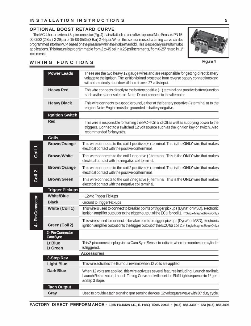
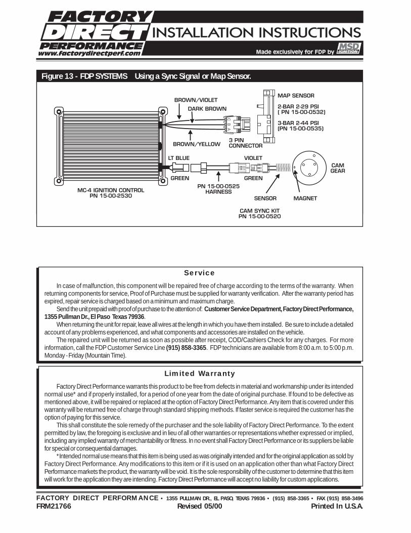
OPTIONAL BOOST RETARD CURVEThe MC-4 has an external 3 - pin connector (Fig. 4) that will attach to one of two optional Map Sensors PN 15-
00-0532 (2 Bar) 2-29 psi or 15-00-0535 (3 Bar) 2-44 psi. When this sensor is used, a timing curve can beprogrammed into the MC-4 based on the pressure within the intake manifold. This is especially useful for turboapplications. This feature is programmable from 2 to 45 psi in 0.25 psi increments, from 0-25° retard in .1°increments.
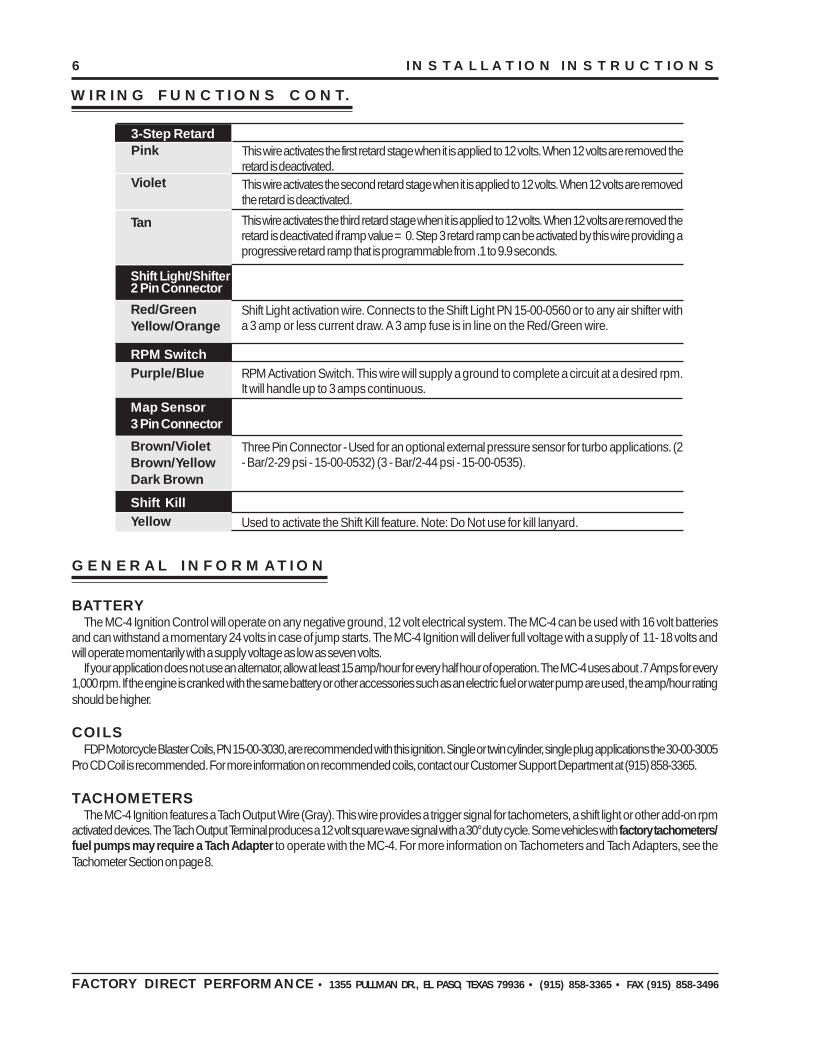
WIRING FUNCTIONS
These are the two heavy 12 gauge wires and are responsible for getting direct batteryvoltage to the ignition. The Ignition is load protected from reverse battery connections andwill automatically shut down if there is over 27 volts input.
Power Leads
Heavy Red
Heavy Black
This wire is responsible for turning the MC-4 On and Off as well as supplying power to thetriggers. Connect to a switched 12 volt source such as the ignition key or switch. Alsorecommended for lanyards.
Ignition Switch
Red
CoilsBrown/Orange
Brown/White
Brown/Orange
Brown/Green
Co
il 1
Co
il 2
4 - P
in C
onne
ctor +12V to Trigger Pickups
This wire connects directly to the battery positive (+) terminal or a positive battery junctionsuch as the starter solenoid. Note: Do not connect to the alternator.
This wire connects to a good ground, either at the battery negative (-) terminal or to theengine. Note: Engine must be grounded to battery negative.
This wire connects to the coil 1 positive (+) terminal. This is the ONLY wire that makeselectrical contact with the positive coil terminal.
This wire connects to the coil 1 negative (-) terminal. This is the ONLY wire that makeselectrical contact with the negative coil terminal.
This wire connects to the coil 2 negative (-) terminal. This is the ONLY wire that makeselectrical contact with the negative coil terminal.
This wire connects to the coil 2 positive (+) terminal. This is the ONLY wire that makeselectrical contact with the positive coil terminal.
Ground to Trigger PickupsThis wire is used to connect to breaker points or trigger pickups (Dyna* or MSD), electronicignition amplifier output or to the trigger output of the ECU for coil 1. (*Single Magnet Rotor Only.)
This wire is used to connect to breaker points or trigger pickups (Dyna* or MSD), electronicignition amplifier output or to the trigger output of the ECU for coil 2. (*Single Magnet Rotor Only.)
Trigger PickupsWhite/BlueBlack
White (Coil 1)
Green (Coil 2)
This 2-pin connector plugs into a Cam Sync Sensor to indicate when the number one cylinderis triggered.
This wire activates the Burnout rev limit when 12 volts are applied.
2 - Pin ConnectorCam SyncLt BlueLt Green
When 12 volts are applied, this wire activates several features including; Launch rev limit,Launch Retard value, Launch Timing Curve and will reset the Shift Light sequence to 1st gear& Step 3 slope.
Used to provide a tach signal to rpm sensing devices. 12 volt square wave with 30° duty cycle.Tach OutputGray
Accessories3-Step RevLight Blue
Dark Blue
Figure 4
6 INSTALLATION INSTRUCTIONS
AUTOTRONIC CONTROLS CORPORATION • 1490 HENRY BRENNAN DR., EL PASO, TEXAS 79936 • (915) 857-5200 • FAX (915) 857-3344
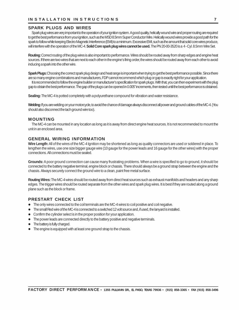
WIRING FUNCTIONS CONT.
FACTORY DIRECT PERFORMANCE • 1355 PULLMAN DR., EL PASO, TEXAS 79936 • (915) 858-3365 • FAX (915) 858-3496
GENERAL INFORMATION
BATTERYThe MC-4 Ignition Control will operate on any negative ground, 12 volt electrical system. The MC-4 can be used with 16 volt batteries
and can withstand a momentary 24 volts in case of jump starts. The MC-4 Ignition will deliver full voltage with a supply of 11- 18 volts andwill operate momentarily with a supply voltage as low as seven volts.
If your application does not use an alternator, allow at least 15 amp/hour for every half hour of operation. The MC-4 uses about .7 Amps for every1,000 rpm. If the engine is cranked with the same battery or other accessories such as an electric fuel or water pump are used, the amp/hour ratingshould be higher.
COILSFDP Motorcycle Blaster Coils, PN 15-00-3030, are recommended with this ignition. Single or twin cylinder, single plug applications the 30-00-3005
Pro CD Coil is recommended. For more information on recommended coils, contact our Customer Support Department at (915) 858-3365.
TACHOMETERSThe MC-4 Ignition features a Tach Output Wire (Gray). This wire provides a trigger signal for tachometers, a shift light or other add-on rpm
activated devices. The Tach Output Terminal produces a 12 volt square wave signal with a 30° duty cycle. Some vehicles with factory tachometers/fuel pumps may require a Tach Adapter to operate with the MC-4. For more information on Tachometers and Tach Adapters, see theTachometer Section on page 8.
3-Step RetardPink
Violet
Tan
Shift Light/Shifter2 Pin Connector
Red/GreenYellow/Orange
RPM SwitchPurple/Blue
Map Sensor3 Pin Connector
Brown/VioletBrown/YellowDark Brown
Shift KillYellow
This wire activates the third retard stage when it is applied to 12 volts. When 12 volts are removed theretard is deactivated if ramp value = 0. Step 3 retard ramp can be activated by this wire providing aprogressive retard ramp that is programmable from .1 to 9.9 seconds.
Shift Light activation wire. Connects to the Shift Light PN 15-00-0560 or to any air shifter witha 3 amp or less current draw. A 3 amp fuse is in line on the Red/Green wire.
RPM Activation Switch. This wire will supply a ground to complete a circuit at a desired rpm.It will handle up to 3 amps continuous.
Three Pin Connector - Used for an optional external pressure sensor for turbo applications. (2- Bar/2-29 psi - 15-00-0532) (3 - Bar/2-44 psi - 15-00-0535).
Used to activate the Shift Kill feature. Note: Do Not use for kill lanyard.
This wire activates the first retard stage when it is applied to 12 volts. When 12 volts are removed theretard is deactivated.This wire activates the second retard stage when it is applied to 12 volts. When 12 volts are removedthe retard is deactivated.
INSTALLATION INSTRUCTIONS 7
AUTOTRONIC CONTROLS CORPORATION • 1490 HENRY BRENNAN DR., EL PASO, TEXAS 79936 • (915) 857-5200 • FAX (915) 857-3344
SPARK PLUGS AND WIRESSpark plug wires are very important to the operation of your ignition system. A good quality, helically wound wire and proper routing are required
to get the best performance from your ignition, such as the MSD 8.5mm Super Conductor Wire. Helically wound wires provide a good path for thespark to follow while keeping Electro Magnetic Interference (EMI) to a minimum. Excessive EMI, such as the amount that solid core wires produce,will interfere with the operation of the MC-4. Solid Core spark plug wires cannot be used. The PN 20-00-3520 is a 4 - Cyl. 8.5mm Wire Set.
Routing: Correct routing of the plug wires is also important to performance. Wires should be routed away from sharp edges and engine heatsources. If there are two wires that are next to each other in the engine’s firing order, the wires should be routed away from each other to avoidinducing a spark into the other wire.
Spark Plugs: Choosing the correct spark plug design and heat range is important when trying to get the best performance possible. Since thereare so many engine combinations and manufacturers, FDP cannot recommend which plug or gap is exactly right for your application.
It is recommended to follow the engine builder or manufacturer’s specification for spark plugs. With that, you can then experiment with the pluggap to obtain the best performance. The gap of the plugs can be opened in 0.005" increments, then tested until the best performance is obtained.
Sealing: The MC-4 is potted completely with a polyurethane compound for vibration and water resistance.
Welding: If you are welding on your motorcycle, to avoid the chance of damage always disconnect all power and ground cables of the MC-4. (Youshould also disconnect the tach ground wire too).
MOUNTINGThe MC-4 can be mounted in any location as long as it is away from direct engine heat sources. It is not recommended to mount the
unit in an enclosed area.
GENERAL WIRING INFORMATIONWire Length: All of the wires of the MC-4 Ignition may be shortened as long as quality connectors are used or soldered in place. Tolengthen the wires, use one size bigger gauge wire (10 gauge for the power leads and 16 gauge for the other wires) with the properconnections. All connections must be sealed.
Grounds: A poor ground connection can cause many frustrating problems. When a wire is specified to go to ground, it should beconnected to the battery negative terminal, engine block or chassis. There should always be a ground strap between the engine and thechassis. Always securely connect the ground wire to a clean, paint free metal surface.
Routing Wires: The MC-4 wires should be routed away from direct heat sources such as exhaust manifolds and headers and any sharpedges. The trigger wires should be routed separate from the other wires and spark plug wires. It is best if they are routed along a groundplane such as the block or frame.
PRESTART CHECK LIST• The only wires connected to the coil terminals are the MC-4 wires to coil positive and coil negative.
• The small Red wire of the MC-4 is connected to a switched 12 volt source and, if used, the lanyard is installed.
• Confirm the cylinder select is in the proper position for your application.
• The power leads are connected directly to the battery positive and negative terminals.
• The battery is fully charged.
• The engine is equipped with at least one ground strap to the chassis.
FACTORY DIRECT PERFORMANCE • 1355 PULLMAN DR., EL PASO, TEXAS 79936 • (915) 858-3365 • FAX (915) 858-3496
8 INSTALLATION INSTRUCTIONS
AUTOTRONIC CONTROLS CORPORATION • 1490 HENRY BRENNAN DR., EL PASO, TEXAS 79936 • (915) 857-5200 • FAX (915) 857-3344
TROUBLESHOOTING
Every FDP Ignition undergoes numerous quality control checks including a four hour burn-in test. If you experience a problem with your MC-4, our research has shown that the majority of problems are due to improper installation or poor connections. The Troubleshooting section hasseveral checks and tests you can perform to ensure proper installation and operation of the MC-4. If you have any questions concerning your MC-4, call our Customer Support Department at (915) 858-3365, 8 - 5 Mountain Time, or e-mail at: [email protected].
LEDThe LED on the side of the MC-4 monitors several operating conditions of the MC-4. If the LED indicates that there is a problem with
the ignition system, follow the steps through the Troubleshooting section. The LED will appear to be on steady at above idle speeds wheneverything is functioning properly.
• A Code 2 (flash flash) will flash if there is a problem with the Cam Sync Signal.
• A Code 3 (flash flash flash)will flash if the supply voltage drops below 12 volts, when operating below 3300 rpm.
• The LED will flash for every trigger signal from the crank trigger. You can take advantage of this when statically setting the timing of the engine.
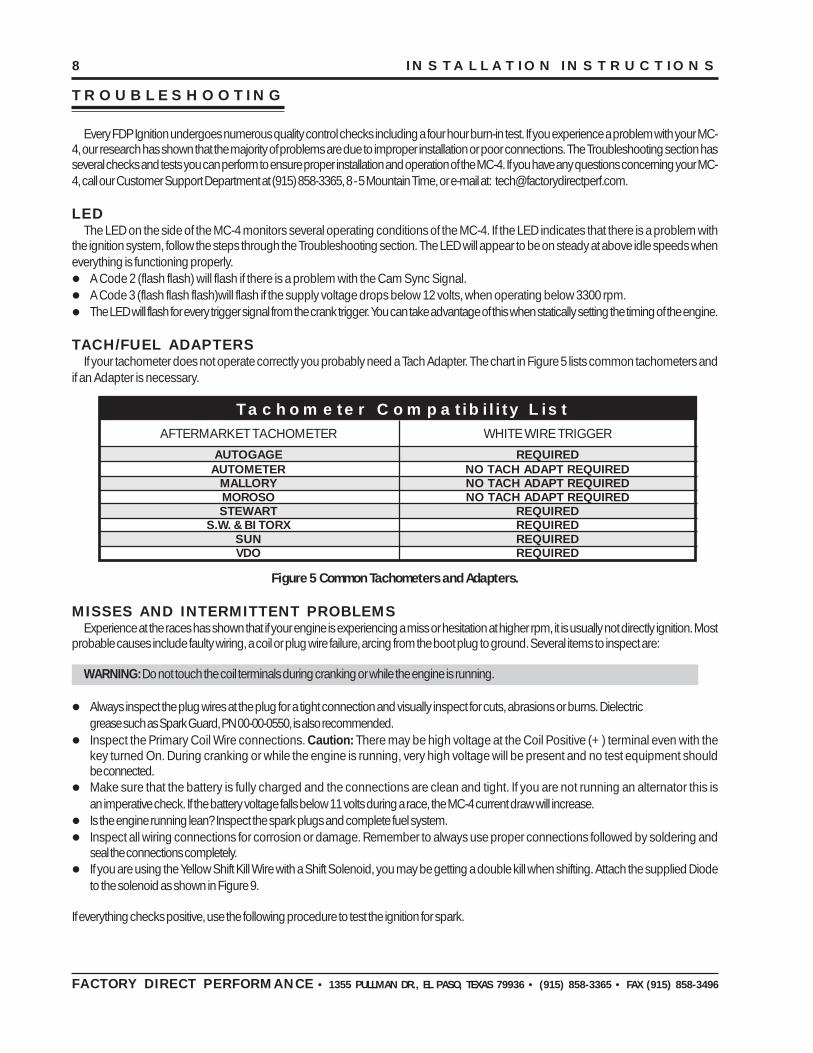
TACH/FUEL ADAPTERSIf your tachometer does not operate correctly you probably need a Tach Adapter. The chart in Figure 5 lists common tachometers and
if an Adapter is necessary.
Figure 5 Common Tachometers and Adapters.
MISSES AND INTERMITTENT PROBLEMSExperience at the races has shown that if your engine is experiencing a miss or hesitation at higher rpm, it is usually not directly ignition. Most
probable causes include faulty wiring, a coil or plug wire failure, arcing from the boot plug to ground. Several items to inspect are:
WARNING: Do not touch the coil terminals during cranking or while the engine is running.
• Always inspect the plug wires at the plug for a tight connection and visually inspect for cuts, abrasions or burns. Dielectricgrease such as Spark Guard, PN 00-00-0550, is also recommended.
• Inspect the Primary Coil Wire connections. Caution: There may be high voltage at the Coil Positive (+) terminal even with thekey turned On. During cranking or while the engine is running, very high voltage will be present and no test equipment shouldbe connected.
• Make sure that the battery is fully charged and the connections are clean and tight. If you are not running an alternator this isan imperative check. If the battery voltage falls below 11 volts during a race, the MC-4 current draw will increase.
• Is the engine running lean? Inspect the spark plugs and complete fuel system.
• Inspect all wiring connections for corrosion or damage. Remember to always use proper connections followed by soldering andseal the connections completely.
• If you are using the Yellow Shift Kill Wire with a Shift Solenoid, you may be getting a double kill when shifting. Attach the supplied Diodeto the solenoid as shown in Figure 9.
If everything checks positive, use the following procedure to test the ignition for spark.
Tachometer Compatibility ListAFTERMARKET TACHOMETER WHITE WIRE TRIGGER
AUTOGAGE REQUIREDAUTOMETER NO TACH ADAPT REQUIRED
MALLORY NO TACH ADAPT REQUIREDMOROSO NO TACH ADAPT REQUIREDSTEWART REQUIRED
S.W. & BI TORX REQUIREDSUN REQUIREDVDO REQUIRED
FACTORY DIRECT PERFORMANCE • 1355 PULLMAN DR., EL PASO, TEXAS 79936 • (915) 858-3365 • FAX (915) 858-3496

INSTALLATION INSTRUCTIONS 9
AUTOTRONIC CONTROLS CORPORATION • 1490 HENRY BRENNAN DR., EL PASO, TEXAS 79936 • (915) 857-5200 • FAX (915) 857-3344
FDP also offers an Ignition Tester (Fig. 6), PN 15-00-1505. This tool allows you to check your complete ignitionsystem while it is on the bike as well as the operation of rpm limits, activated switches and shift lights and the CamSync Signal.
CHECKING FOR SPARK1. Make sure the ignition switch is in the “Off” position.2. Remove the coil wires from the spark plug and set them approximately 1/2" from ground.3. Disconnect the MC-4 wire from the points or trigger.4. Connect the Green wire to ground.5. Turn the ignition to the On position. Do not crank the engine.6. Tap the white wire to ground quickly several times (Figure 7). Each time you pull the
wires from ground, a spark should jump from the coil wires to ground. If spark ispresent, the ignition is working properly. Do the same test using the Green Triggerwire. If there is no spark skip to step 7 below:
7. If there is no spark:A. Inspect all of the wiring.B. Substitute another coil and repeat the test. If there is now spark, the coil is at
fault.C. If there is still no spark, check to make sure there are 12 volts on the small Red
wire from the MC-4 when the key is in the On position. If 12 volts are not present, find another switched 12 volt source and repeatthe test.
D. If, after following the test procedures and inspecting all of the wiring, there is still no spark, the MC-4 Ignition is in need of repair. Seethe Warranty and Service section for information.
The following wiring diagrams illustrate numerous installations on different vehicles and applications. If you experience difficulties wheninstalling your MSD, contact our Customer Support Department at (915) 858-3365 (8 - 5 Mountain time) or e-mail us at:[email protected]
FACTORY DIRECT PERFORMANCE • 1355 PULLMAN DR., EL PASO, TEXAS 79936 • (915) 858-3365 • FAX (915) 858-3496
Figure 7 Checking for Spark with theWhite Wire.
WHITE WIRE TRIGGER
Figure 8 - FDP SYSTEMS Wiring Diagram for Burnout/Launch Rev Limits.
Figure 6
10 INSTALLATION INSTRUCTIONS
AUTOTRONIC CONTROLS CORPORATION • 1490 HENRY BRENNAN DR., EL PASO, TEXAS 79936 • (915) 857-5200 • FAX (915) 857-3344FACTORY DIRECT PERFORMANCE • 1355 PULLMAN DR., EL PASO, TEXAS 79936 • (915) 858-3365 • FAX (915) 858-3496
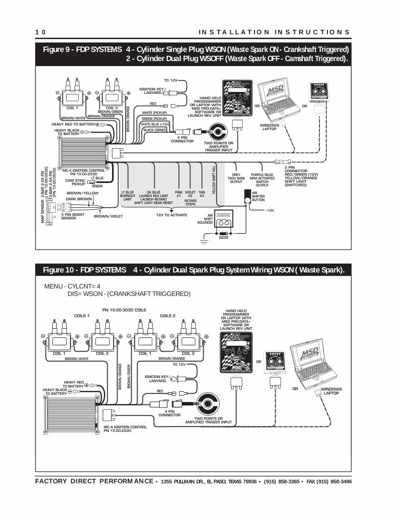
Figure 9 - FDP SYSTEMS 4 - Cylinder Single Plug WSON (Waste Spark ON - Crankshaft Triggered)2 - Cylinder Dual Plug WSOFF (Waste Spark OFF - Camshaft Triggered).
Figure 10 - FDP SYSTEMS 4 - Cylinder Dual Spark Plug System Wiring WSON ( Waste Spark).
MENU - CYLCNT=4DIS=WSON - (CRANKSHAFT TRIGGERED)

INSTALLATION INSTRUCTIONS 11
AUTOTRONIC CONTROLS CORPORATION • 1490 HENRY BRENNAN DR., EL PASO, TEXAS 79936 • (915) 857-5200 • FAX (915) 857-3344FACTORY DIRECT PERFORMANCE • 1355 PULLMAN DR., EL PASO, TEXAS 79936 • (915) 858-3365 • FAX (915) 858-3496
Figure 11 - FDP SYSTEMS Single Cylinder Wiring.MENU - CYLCNT=1
DIS=WSON - (Crankshaft Triggered)DIS=WSOFF - (Camshaft Triggered)
Figure 12 - FDP SYSTEMS 2 - Cylinder - Single Fire - WSOFF (No Waste Spark - Harley Davidson®).MENU - CYLCNT=2
DIS=WSOFF - (Camshaft Triggered)
*Harley Davidson is a registered Trademark of Harley Davidson Motor Company
12 INSTALLATION INSTRUCTIONS
AUTOTRONIC CONTROLS CORPORATION • 1490 HENRY BRENNAN DR., EL PASO, TEXAS 79936 • (915) 857-5200 • FAX (915) 857-3344
Service
In case of malfunction, this component will be repaired free of charge according to the terms of the warranty. Whenreturning components for service, Proof of Purchase must be supplied for warranty verification. After the warranty period hasexpired, repair service is charged based on a minimum and maximum charge.
Send the unit prepaid with proof of purchase to the attention of: Customer Service Department, Factory Direct Performance,1355 Pullman Dr., El Paso Texas 79936.
When returning the unit for repair, leave all wires at the length in which you have them installed. Be sure to include a detailedaccount of any problems experienced, and what components and accessories are installed on the vehicle.
The repaired unit will be returned as soon as possible after receipt, COD/Cashiers Check for any charges. For moreinformation, call the FDP Customer Service Line (915) 858-3365. FDP technicians are available from 8:00 a.m. to 5:00 p.m.Monday - Friday (Mountain Time).
Limited Warranty
Factory Direct Performance warrants this product to be free from defects in material and workmanship under its intendednormal use* and if properly installed, for a period of one year from the date of original purchase. If found to be defective asmentioned above, it will be repaired or replaced at the option of Factory Direct Performance. Any item that is covered under thiswarranty will be returned free of charge through standard shipping methods. If faster service is required the customer has theoption of paying for this service.
This shall constitute the sole remedy of the purchaser and the sole liability of Factory Direct Performance. To the extentpermitted by law, the foregoing is exclusive and in lieu of all other warranties or representations whether expressed or implied,including any implied warranty of merchantability or fitness. In no event shall Factory Direct Performance or its suppliers be liablefor special or consequential damages.
*Intended normal use means that this item is being used as was originally intended and for the original application as sold byFactory Direct Performance. Any modifications to this item or if it is used on an application other than what Factory DirectPerformance markets the product, the warranty will be void. It is the sole responsibility of the customer to determine that this itemwill work for the application they are intending. Factory Direct Performance will accept no liability for custom applications.
FACTORY DIRECT PERFORMANCE • 1355 PULLMAN DR., EL PASO, TEXAS 79936 • (915) 858-3365 • FAX (915) 858-3496
FRM21766 Revised 05/00 Printed In U.S.A.
Figure 13 - FDP SYSTEMS Using a Sync Signal or Map Sensor.