Programmable Logic Controllers - etf.ues.rs.baslubura/Procesni racunari/Programmable...
303
Transcript of Programmable Logic Controllers - etf.ues.rs.baslubura/Procesni racunari/Programmable...

Programmable Logic Controllers

Programmable Logic Controllers
Fourth Edition
W. Bolton
AMSTERDAM • BOSTON • HEIDELBERG • LONDON • NEW YORK • OXFORD PARIS • SAN DIEGO • SAN FRANCISCO • SINGAPORE • SYDNEY • TOKYO
ELSEVIER Newnes is an imprint of Elsevier Newnes

Newnes is an imprint of Elsevier Linacre House, Jordan Hill, Oxford OX2 8DP30 Corporate Drive, Suite 400, Burlington, MA 01803
First edition 1996Second edition 2000Third edition 2003Fourth edition 2006
Copyright 2006, W. Bolton. Published by Elsevier Newnes. All rights reserved
The right of W. Bolton to be identified as the author of this work has beenasserted in accordance with the Copyright, Designs and Patents Act 1988
No part of this publication may be reproduced, stored in a retrieval systemor transmitted in any form or by any means electronic, mechanical, photocopying,recordinh or otherwise without the prior permission of the publisher
Permissions may be sought directly from Elsevier’s Science & Technology RightsDepartment in Oxford, UK; phone: (+44) 1865 843830; fax: (+44) (0) 1865 853333;e-mail: [email protected]. Alternatively you can submit your request on-line byvisiting the Elsevier web site at http:www.elsevier.com/locate/permissions, and selecting Obtaining permission to use Elsevier material
NoticeNo responsibility is assumed by the publisher for any injury and/or damage to personsor property as a matter of products liability, negligence or otherwise, or from any useor operation of any methods, products, instructions or ideas contained in the materialherin. Because of rapid advances in the medical sciences, in particular, independentverification of diganoses and drug dosages should be made
British Library Cataloguing in Publication DataA catalogue record for this book is available from the British Library
Library of Congress Cataloging -in-Publication DataA catalog record for this book is available from the Library of Congress
ISBN-13: 978-0-7506-8112-4ISBN-10: 0-7506-8112-8
Printed and bound in the UK06 07 08 09 10 10 9 8 7 6 5 4 3 2 1
InternationalSabre FoundationBOOK AIDELSEVIER
www.elsevier.com | www.bookaid.org | www.sabre.org
Working together to grow libraries in developing countries
For information on all Newnes publications visitour website at www.newnespress.com
Contents
Preface vii
145
1015
ControllersHardwareInternal architecturePLC systemsProblems
1.11.21.31.4
Programmable logiccontrollers
1
17303941
Input devicesOutput devicesExamples of applicationsProblems
2.12.22.3
Input-output devices2
4445475152
The binary systemOctal and hexadecimalBinary arithmeticPLC dataProblems
3.13.23.33.4
Number systems3
53596269757677
Input/output unitsSignal conditioningRemote connectionsNetworksProcessing inputsI/O addressesProblems
4.14.24.34.44.54.6
I/O processing4
808490919394
100103
Ladder diagramsLogic functionsLatchingMultiple outputsEntering programsFunction blocksProgram examplesProblems
5.15.25.35.45.55.65.7
Ladder and functionalblock programming
5
108115120124
Intruction listsSequential function chartsStructured textProblems
6.16.26.3
IL, SFC and STprogramming methods
6
132133136
Internal relaysLadder programsBattery-backed relays
7.17.27.3
Internal relays7
137138142146
One-shot operationSet and resetMaster control relayProblems
7.47.57.6
154156157
JumpSubroutinesProblems
8.18.2
Jump and call8
159160163165166167
Types of timersProgramming timersOff-delay timersPulse timersProgramming examplesProblems
9.19.29.39.49.5
Timers9
173174178179180182
Forms of counterProgrammingUp and down countingTimers with countersSequencerProblems
10.110.210.310.410.5
Counters10
189190194
Shift registersLadder programsProblems
11.111.2
Shift registers11
197198202203206
Registers and bitsData handlingArithmetic functionsClosed loop controlProblems
12.112.212.312.4
Data handling12
210214218220227248
Program developmentSafe systemsCommissioningFault findingSystem documentationProblems
13.113.213.313.413.5
Designing systems13
250254265269271
Temperature controlValve sequencingConveyor belt controlControl of a processProblems
14.114.214.314.4
Programs14
276Appendix: Symbols281288
AnswersIndex
vi Contents

Preface
Technological advances in recent years have resulted in the developmentof the programmable logic controller and a consequential revolution ofcontrol engineering. This book is an introduction to programmable logiccontrollers and aims to ease the tasks of practising engineers coming firstinto contact with programmable logic controllers, and also provides abasic course for students on courses such as Nationals and HigherNationals in Engineering, company training programmes and as anintroduction for first year undergraduate courses in engineering.
The book has been designed to provide full syllabus coverage of theBTEC National and Higher National in Engineering units ProgrammableControllers and Programmable Logic Controllers from Edexcel. Itaddresses the problem of different programmable control manufacturersusing different nomenclature and program forms by describing theprinciples involved and illustrating them with examples from a range ofmanufacturers. The text includes:
w The basic architecture of PLCs and the characteristics of commonlyused input and outputs to such systems.
w A discussion of the number systems: denary, binary, octal,hexadecimal and BCD.
w A painstaking methodical introduction, with lots of illustrations, ofhow to program PLCs, whatever the manufacturer, and make use ofinternal relays, timers, counters, shift registers, sequencers and datahandling facilities.
w Consideration of the standards given by IEC 1131-3 and theprogramming methods of ladder, functional block diagram,instruction list, structured text and sequential function chart.
w To assist the reader to develop the skills necessary to write programsfor programmable logic controllers, many worked examples,multi-choice questions and problems are included in the book withanswers to all multi-choice questions and problems given at the endof the book.
Changes from third edition
The fourth edition is a complete restructuring and updating of the thirdedition and includes a more detailed consideration of IEC 1131-3,including all the programming methods given in the standard, and theproblems of safety. This includes a discussion of emergency stop relaysand safety PLCs.

Aims
This book aims to enable the reader to:
w Identify and explain the main design characteristics, internalarchitecture and operating principles of programmable logiccontrollers.
w Describe and identify the characteristics of commonly used input andoutput devices.
w Explain the processing of inputs and outputs by PLCs.w Describe communication links involved with PLC systems, the
protocols and networking methods.w Develop ladder programs for the logic functions AND, OR, NOR,
NAND, NOT and XOR.w Develop ladder programs involving internal relays, timers, counters,
shift registers, sequencers and data handling.w Develop functional block diagram, instruction list, structured text and
sequential function chart programs. w Identify safety issues with PLC systems.w Identify methods used for fault diagnosis, testing and debugging.
Structure of the book
The figure on the following page outlines the structure of the book.
W. Bolton
viii Preface

Design and operationalcharacteristics
PLC information andcommunication techniques
Programmingtechniques
Chapter 1Programmable logic
controllers
Chapter 2Input-output
devices
Chapter 4I/O processing
Chapter 5
block programming
Chapter 7Internal relays
Chapter 9Timers
Chapter 10Counters
Chapter 11Shift registers
Chapter 12Data handling
Chapter 13Designing programs
Chapter 14Programs
Number systemsChapter 3
Programmingmethods
Ladder and functional
Chapter 6IL, SFC and ST
programming methods
Chapter 8Jump and call
Preface ix

1 Programmable logic controllers
This chapter is an introduction to the programmable logic controller, itsgeneral function, hardware forms and internal architecture. This overviewis followed up by more detailed discussion in the following chapters.
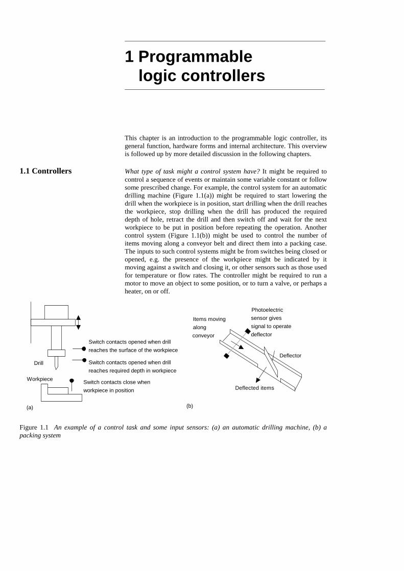
1.1 Controllers What type of task might a control system have? It might be required tocontrol a sequence of events or maintain some variable constant or followsome prescribed change. For example, the control system for an automaticdrilling machine (Figure 1.1(a)) might be required to start lowering thedrill when the workpiece is in position, start drilling when the drill reachesthe workpiece, stop drilling when the drill has produced the requireddepth of hole, retract the drill and then switch off and wait for the nextworkpiece to be put in position before repeating the operation. Anothercontrol system (Figure 1.1(b)) might be used to control the number ofitems moving along a conveyor belt and direct them into a packing case.The inputs to such control systems might be from switches being closed oropened, e.g. the presence of the workpiece might be indicated by itmoving against a switch and closing it, or other sensors such as those usedfor temperature or flow rates. The controller might be required to run amotor to move an object to some position, or to turn a valve, or perhaps aheater, on or off.
Drill
Workpiece Switch contacts close whenworkpiece in position
Switch contacts opened when drillreaches the surface of the workpiece
Switch contacts opened when drill reaches required depth in workpiece
Photoelectricsensor givessignal to operatedeflector
Deflector
Deflected items
Items movingalongconveyor
(a) (b)
Figure 1.1 An example of a control task and some input sensors: (a) an automatic drilling machine, (b) apacking system

What form might a controller have? For the automatic drillingmachine, we could wire up electrical circuits in which the closing oropening of switches would result in motors being switched on or valvesbeing actuated. Thus we might have the closing of a switch activating arelay which, in turn, switches on the current to a motor and causes the drillto rotate (Figure 1.2). Another switch might be used to activate a relay andswitch on the current to a pneumatic or hydraulic valve which results inpressure being switched to drive a piston in a cylinder and so results in theworkpiece being pushed into the required position. Such electrical circuitswould have to be specific to the automatic drilling machine. Forcontrolling the number of items packed into a packing case we couldlikewise wire up electrical circuits involving sensors and motors.However, the controller circuits we devised for these two situations wouldbe different. In the ‘traditional’ form of control system, the rulesgoverning the control system and when actions are initiated aredetermined by the wiring. When the rules used for the control actions arechanged, the wiring has to be changed.
Motor
Relay toswitch onlarge current to motor
Lowvoltage
Switch
Figure 1.2 A control circuit
1.1.1 Microprocessor controlled system
Instead of hardwiring each control circuit for each control situation wecan use the same basic system for all situations if we use amicroprocessor-based system and write a program to instruct themicroprocessor how to react to each input signal from, say, switches andgive the required outputs to, say, motors and valves. Thus we might havea program of the form:
If switch A closesOutput to motor circuitIf switch B closesOutput to valve circuit
By changing the instructions in the program we can use the samemicroprocessor system to control a wide variety of situations.
As an illustration, the modern domestic washing machine uses amicroprocessor system. Inputs to it arise from the dials used to select therequired wash cycle, a switch to determine that the machine door isclosed, a temperature sensor to determine the temperature of the water and
2 Programmable Logic Controllers

a switch to detect the level of the water. On the basis of these inputs themicroprocessor is programmed to give outputs which switch on the drummotor and control its speed, open or close cold and hot water valves,switch on the drain pump, control the water heater and control the doorlock so that the machine cannot be opened until the washing cycle iscompleted.
1.1.2 The programmable logic controller
A programmable logic controller (PLC) is a special form of micro-processor-based controller that uses a programmable memory to storeinstructions and to implement functions such as logic, sequencing, timing,counting and arithmetic in order to control machines and processes(Figure 1.3) and are designed to be operated by engineers with perhaps alimited knowledge of computers and computing languages. They are notdesigned so that only computer programmers can set up or change theprograms. Thus, the designers of the PLC have pre-programmed it so thatthe control program can be entered using a simple, rather intuitive, formof language, see Chapter 4. The term logic is used because programmingis primarily concerned with implementing logic and switching operations,e.g. if A or B occurs switch on C, if A and B occurs switch on D. Inputdevices, e.g. sensors such as switches, and output devices in the systembeing controlled, e.g. motors, valves, etc., are connected to the PLC. Theoperator then enters a sequence of instructions, i.e. a program, into thememory of the PLC. The controller then monitors the inputs and outputsaccording to this program and carries out the control rules for which it hasbeen programmed.
Program
PLC
Inputs Outputs
Figure 1.3 A programmable logic controller
PLCs have the great advantage that the same basic controller can beused with a wide range of control systems. To modify a control systemand the rules that are to be used, all that is necessary is for an operator tokey in a different set of instructions. There is no need to rewire. The resultis a flexible, cost effective, system which can be used with control systemswhich vary quite widely in their nature and complexity.
PLCs are similar to computers but whereas computers are optimised forcalculation and display tasks, PLCs are optimised for control tasks and theindustrial environment. Thus PLCs are:
1 Rugged and designed to withstand vibrations, temperature, humidityand noise.
2 Have interfacing for inputs and outputs already inside the controller.
Programmable logic controllers 3
3 Are easily programmed and have an easily understood programminglanguage which is primarily concerned with logic and switchingoperations.
The first PLC was developed in 1969. They are now widely used andextend from small self-contained units for use with perhaps 20 digitalinputs/outputs to modular systems which can be used for large numbers ofinputs/outputs, handle digital or analogue inputs/outputs, and also carryout proportional-integral-derivative control modes.
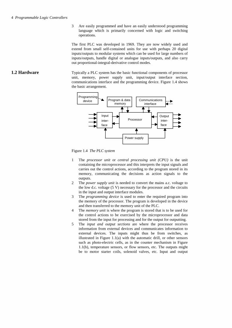
1.2 Hardware Typically a PLC system has the basic functional components of processorunit, memory, power supply unit, input/output interface section,communications interface and the programming device. Figure 1.4 showsthe basic arrangement.
Processor
Programmingdevice
Power supply
Inputinter-face
Outputinter-face
memoryCommunications
interfaceProgram & data
Figure 1.4 The PLC system
1 The processor unit or central processing unit (CPU) is the unitcontaining the microprocessor and this interprets the input signals andcarries out the control actions, according to the program stored in itsmemory, communicating the decisions as action signals to theoutputs.
2 The power supply unit is needed to convert the mains a.c. voltage tothe low d.c. voltage (5 V) necessary for the processor and the circuitsin the input and output interface modules.
3 The programming device is used to enter the required program intothe memory of the processor. The program is developed in the deviceand then transferred to the memory unit of the PLC.
4 The memory unit is where the program is stored that is to be used forthe control actions to be exercised by the microprocessor and datastored from the input for processing and for the output for outputting.
5 The input and output sections are where the processor receivesinformation from external devices and communicates information toexternal devices. The inputs might thus be from switches, asillustrated in Figure 1.1(a) with the automatic drill, or other sensorssuch as photo-electric cells, as in the counter mechanism in Figure1.1(b), temperature sensors, or flow sensors, etc. The outputs mightbe to motor starter coils, solenoid valves, etc. Input and output
4 Programmable Logic Controllers
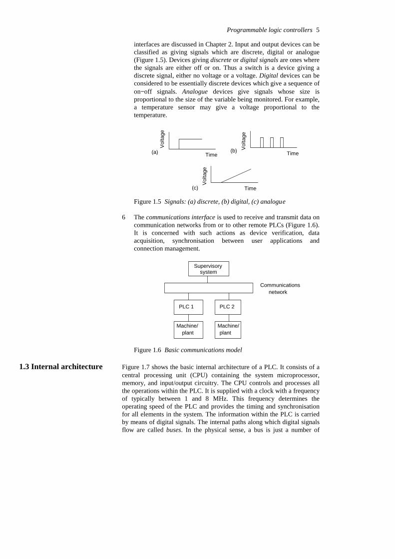
interfaces are discussed in Chapter 2. Input and output devices can beclassified as giving signals which are discrete, digital or analogue(Figure 1.5). Devices giving discrete or digital signals are ones wherethe signals are either off or on. Thus a switch is a device giving adiscrete signal, either no voltage or a voltage. Digital devices can beconsidered to be essentially discrete devices which give a sequence ofon−off signals. Analogue devices give signals whose size isproportional to the size of the variable being monitored. For example,a temperature sensor may give a voltage proportional to thetemperature.
TimeV
olta
ge
(a) Time
Vol
tage
(b)
Time
Vol
tage
(c)
Figure 1.5 Signals: (a) discrete, (b) digital, (c) analogue
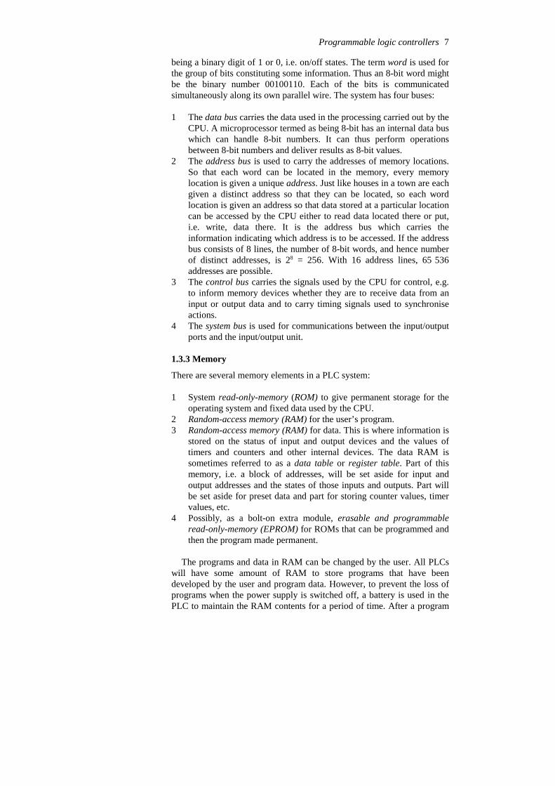
6 The communications interface is used to receive and transmit data oncommunication networks from or to other remote PLCs (Figure 1.6).It is concerned with such actions as device verification, dataacquisition, synchronisation between user applications andconnection management.
Supervisorysystem
PLC 1 PLC 2
Communicationsnetwork
Machine/plant
Machine/plant
Figure 1.6 Basic communications model
1.3 Internal architecture Figure 1.7 shows the basic internal architecture of a PLC. It consists of acentral processing unit (CPU) containing the system microprocessor,memory, and input/output circuitry. The CPU controls and processes allthe operations within the PLC. It is supplied with a clock with a frequencyof typically between 1 and 8 MHz. This frequency determines theoperating speed of the PLC and provides the timing and synchronisationfor all elements in the system. The information within the PLC is carriedby means of digital signals. The internal paths along which digital signalsflow are called buses. In the physical sense, a bus is just a number of
Programmable logic controllers 5

conductors along which electrical signals can flow. It might be tracks on aprinted circuit board or wires in a ribbon cable. The CPU uses the databus for sending data between the constituent elements, the address bus tosend the addresses of locations for accessing stored data and the controlbus for signals relating to internal control actions. The system bus is usedfor communications between the input/output ports and the input/outputunit.
UserprogramRAM
CPUSystemROM
DataRAM
Bat
tery
Input/outputunitC
lock
Address bus
Control bus
Data bus
Program panel
Latch
Output channels
Opto-coupler
Buffer
Input channels
I/O system bus
Driverinterface
Drivers e.g. relays
Figure 1.7 Architecture of a PLC
1.3.1 The CPU
The internal structure of the CPU depends on the microprocessorconcerned. In general they have:
1 An arithmetic and logic unit (ALU) which is responsible for datamanipulation and carrying out arithmetic operations of addition andsubtraction and logic operations of AND, OR, NOT andEXCLUSIVE-OR.
2 Memory, termed registers, located within the microprocessor andused to store information involved in program execution.
3 A control unit which is used to control the timing of operations.
1.3.2 The buses
The buses are the paths used for communication within the PLC. Theinformation is transmitted in binary form, i.e. as a group of bits with a bit
6 Programmable Logic Controllers
being a binary digit of 1 or 0, i.e. on/off states. The term word is used forthe group of bits constituting some information. Thus an 8-bit word mightbe the binary number 00100110. Each of the bits is communicatedsimultaneously along its own parallel wire. The system has four buses:
1 The data bus carries the data used in the processing carried out by theCPU. A microprocessor termed as being 8-bit has an internal data buswhich can handle 8-bit numbers. It can thus perform operationsbetween 8-bit numbers and deliver results as 8-bit values.
2 The address bus is used to carry the addresses of memory locations.So that each word can be located in the memory, every memorylocation is given a unique address. Just like houses in a town are eachgiven a distinct address so that they can be located, so each wordlocation is given an address so that data stored at a particular locationcan be accessed by the CPU either to read data located there or put,i.e. write, data there. It is the address bus which carries theinformation indicating which address is to be accessed. If the addressbus consists of 8 lines, the number of 8-bit words, and hence numberof distinct addresses, is 28 = 256. With 16 address lines, 65 536addresses are possible.
3 The control bus carries the signals used by the CPU for control, e.g.to inform memory devices whether they are to receive data from aninput or output data and to carry timing signals used to synchroniseactions.
4 The system bus is used for communications between the input/outputports and the input/output unit.
1.3.3 Memory
There are several memory elements in a PLC system:
1 System read-only-memory (ROM) to give permanent storage for theoperating system and fixed data used by the CPU.
2 Random-access memory (RAM) for the user’s program. 3 Random-access memory (RAM) for data. This is where information is
stored on the status of input and output devices and the values oftimers and counters and other internal devices. The data RAM issometimes referred to as a data table or register table. Part of thismemory, i.e. a block of addresses, will be set aside for input andoutput addresses and the states of those inputs and outputs. Part willbe set aside for preset data and part for storing counter values, timervalues, etc.
4 Possibly, as a bolt-on extra module, erasable and programmableread-only-memory (EPROM) for ROMs that can be programmed andthen the program made permanent.
The programs and data in RAM can be changed by the user. All PLCswill have some amount of RAM to store programs that have beendeveloped by the user and program data. However, to prevent the loss ofprograms when the power supply is switched off, a battery is used in thePLC to maintain the RAM contents for a period of time. After a program
Programmable logic controllers 7
has been developed in RAM it may be loaded into an EPROM memorychip, often a bolt-on module to the PLC, and so made permanent. Inaddition there are temporary buffer stores for the input/output channels.
The storage capacity of a memory unit is determined by the number ofbinary words that it can store. Thus, if a memory size is 256 words then itcan store 256 × 8 = 2048 bits if 8-bit words are used and 256 × 16 = 4096bits if 16-bit words are used. Memory sizes are often specified in terms ofthe number of storage locations available with 1K representing thenumber 210, i.e. 1024. Manufacturers supply memory chips with thestorage locations grouped in groups of 1, 4 and 8 bits. A 4K % 1 memoryhas 4 % 1 % 1024 bit locations. A 4K % 8 memory has 4 % 8 % 1024 bitlocations. The term byte is used for a word of length 8 bits. Thus the 4K %8 memory can store 4096 bytes. With a 16-bit address bus we can have 216
different addresses and so, with 8-bit words stored at each address, we canhave 216 % 8 storage locations and so use a memory of size 216 % 8/210 =64K % 8 which we might be as four 16K % 8 bit memory chips.
1.3.4 Input/output unit
The input/output unit provides the interface between the system and theoutside world, allowing for connections to be made through input/outputchannels to input devices such as sensors and output devices such asmotors and solenoids. It is also through the input/output unit thatprograms are entered from a program panel. Every input/output point hasa unique address which can be used by the CPU. It is like a row of housesalong a road, number 10 might be the ‘house’ to be used for an input froma particular sensor while number ‘45’ might be the ‘house’ to be used forthe output to a particular motor.
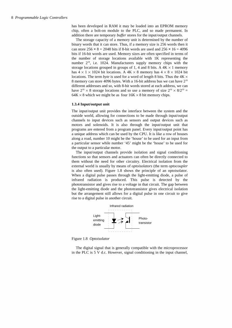
The input/output channels provide isolation and signal conditioningfunctions so that sensors and actuators can often be directly connected tothem without the need for other circuitry. Electrical isolation from theexternal world is usually by means of optoisolators (the term optocoupleris also often used). Figure 1.8 shows the principle of an optoisolator.When a digital pulse passes through the light-emitting diode, a pulse ofinfrared radiation is produced. This pulse is detected by thephototransistor and gives rise to a voltage in that circuit. The gap betweenthe light-emitting diode and the phototransistor gives electrical isolationbut the arrangement still allows for a digital pulse in one circuit to giverise to a digital pulse in another circuit.
Photo-transistor
Light-emittingdiode
Infrared radiation
Figure 1.8 Optoisolator
The digital signal that is generally compatible with the microprocessorin the PLC is 5 V d.c. However, signal conditioning in the input channel,
8 Programmable Logic Controllers
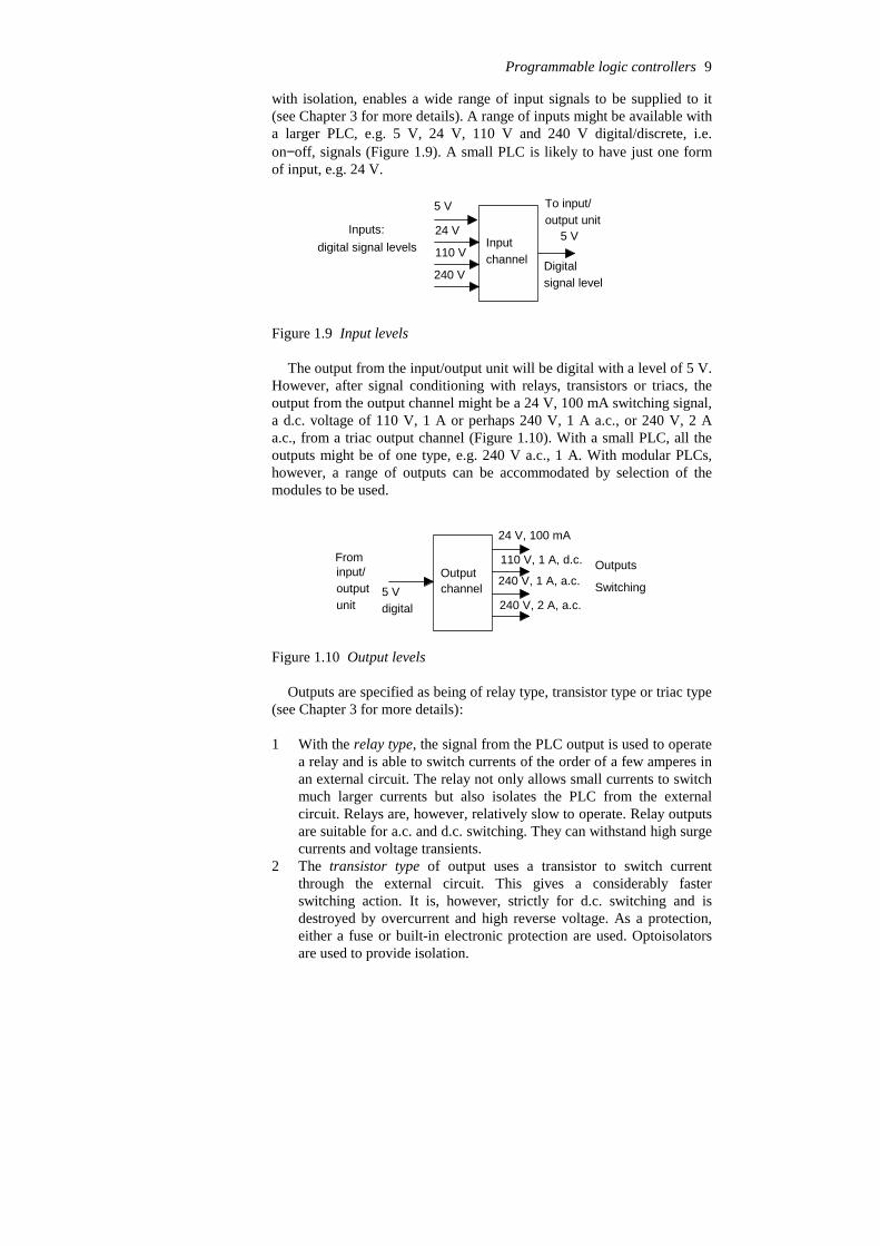
with isolation, enables a wide range of input signals to be supplied to it(see Chapter 3 for more details). A range of inputs might be available witha larger PLC, e.g. 5 V, 24 V, 110 V and 240 V digital/discrete, i.e.on−off, signals (Figure 1.9). A small PLC is likely to have just one formof input, e.g. 24 V.
Inputchannel
5 V
24 V
110 V
240 V
5 VInputs:digital signal levels
To input/output unit
Digitalsignal level
Figure 1.9 Input levels
The output from the input/output unit will be digital with a level of 5 V.However, after signal conditioning with relays, transistors or triacs, theoutput from the output channel might be a 24 V, 100 mA switching signal,a d.c. voltage of 110 V, 1 A or perhaps 240 V, 1 A a.c., or 240 V, 2 Aa.c., from a triac output channel (Figure 1.10). With a small PLC, all theoutputs might be of one type, e.g. 240 V a.c., 1 A. With modular PLCs,however, a range of outputs can be accommodated by selection of themodules to be used.
channel
24 V, 100 mA
110 V, 1 A, d.c.
240 V, 1 A, a.c.
240 V, 2 A, a.c.Switching
OutputsOutputFrom input/outputunit
5 Vdigital
Figure 1.10 Output levels
Outputs are specified as being of relay type, transistor type or triac type(see Chapter 3 for more details):
1 With the relay type, the signal from the PLC output is used to operatea relay and is able to switch currents of the order of a few amperes inan external circuit. The relay not only allows small currents to switchmuch larger currents but also isolates the PLC from the externalcircuit. Relays are, however, relatively slow to operate. Relay outputsare suitable for a.c. and d.c. switching. They can withstand high surgecurrents and voltage transients.
2 The transistor type of output uses a transistor to switch currentthrough the external circuit. This gives a considerably fasterswitching action. It is, however, strictly for d.c. switching and isdestroyed by overcurrent and high reverse voltage. As a protection,either a fuse or built-in electronic protection are used. Optoisolatorsare used to provide isolation.
Programmable logic controllers 9

3 Triac outputs, with optoisolators for isolation, can be used to controlexternal loads which are connected to the a.c. power supply. It isstrictly for a.c. operation and is very easily destroyed by overcurrent.Fuses are virtually always included to protect such outputs.
1.3.5 Sourcing and sinking
The terms sourcing and sinking are used to describe the way in which d.c.devices are connected to a PLC. With sourcing, using the conventionalcurrent flow direction as from positive to negative, an input devicereceives current from the input module, i.e. the input module is the sourceof the current (Figure 1.11(a)). If the current flows from the outputmodule to an output load then the output module is referred to as sourcing(Figure 1.11(b)). With sinking, using the conventional current flowdirection as from positive to negative, an input device supplies current tothe input module, i.e. the input module is the sink for the current (Figure1.12(a)). If the current flows to the output module from an output loadthen the output module is referred to as sinking (Figure 1.12(b)).
+
–Inputdevice
Inputmodule
(a)
–
Inputmodule
(b) Output load
Figure 1.11 Sourcing
+
–
Inputdevice
Inputmodule
(a)
Inputmodule
(b) Output load
+
Figure 1.12 Sinking
1.4 PLC systems There are two common types of mechanical design for PLC systems; asingle box, and the modular/rack types. The single box type (or, assometimes termed, brick) is commonly used for small programmablecontrollers and is supplied as an integral compact package complete withpower supply, processor, memory, and input/output units. Typically sucha PLC might have 6, 8, 12 or 24 inputs and 4, 8 or 16 outputs and amemory which can store some 300 to 1000 instructions. Figure 1.13shows the Mitsubishi MELSEC FX3U compact, i.e. brick, PLC and Table1.1 gives details of models in that Mitsubishi range.
10 Programmable Logic Controllers
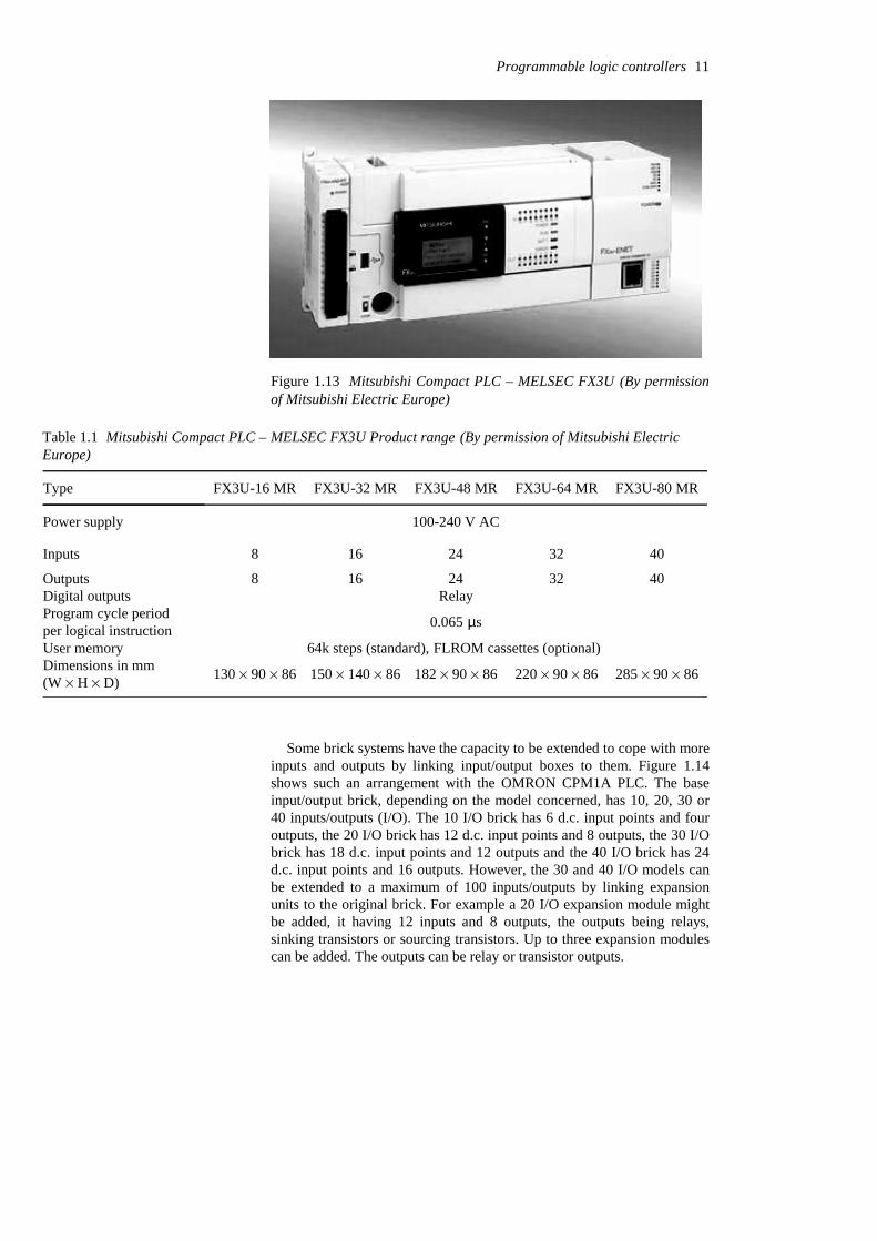
Figure 1.13 Mitsubishi Compact PLC – MELSEC FX3U (By permissionof Mitsubishi Electric Europe)
Table 1.1 Mitsubishi Compact PLC – MELSEC FX3U Product range (By permission of Mitsubishi ElectricEurope)
285 % 90 % 86220 % 90 % 86182 % 90 % 86150 % 140 % 86130 % 90 % 86Dimensions in mm (W % H % D)
64k steps (standard), FLROM cassettes (optional) User memory
0.065 µsProgram cycle periodper logical instruction
RelayDigital outputs 403224168Outputs
403224168Inputs
100-240 V ACPower supply
FX3U-80 MRFX3U-64 MRFX3U-48 MRFX3U-32 MRFX3U-16 MRType
Some brick systems have the capacity to be extended to cope with moreinputs and outputs by linking input/output boxes to them. Figure 1.14shows such an arrangement with the OMRON CPM1A PLC. The baseinput/output brick, depending on the model concerned, has 10, 20, 30 or40 inputs/outputs (I/O). The 10 I/O brick has 6 d.c. input points and fouroutputs, the 20 I/O brick has 12 d.c. input points and 8 outputs, the 30 I/Obrick has 18 d.c. input points and 12 outputs and the 40 I/O brick has 24d.c. input points and 16 outputs. However, the 30 and 40 I/O models canbe extended to a maximum of 100 inputs/outputs by linking expansionunits to the original brick. For example a 20 I/O expansion module mightbe added, it having 12 inputs and 8 outputs, the outputs being relays,sinking transistors or sourcing transistors. Up to three expansion modulescan be added. The outputs can be relay or transistor outputs.
Programmable logic controllers 11
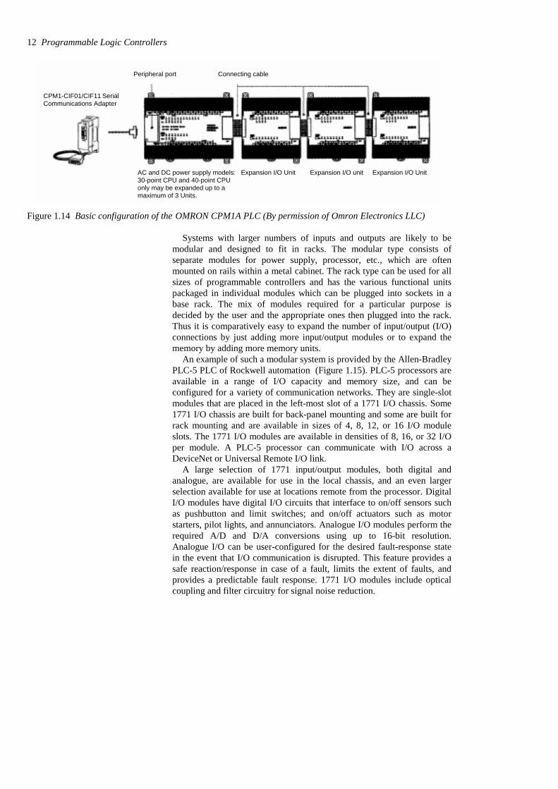
Figure 1.14 Basic configuration of the OMRON CPM1A PLC (By permission of Omron Electronics LLC)
Systems with larger numbers of inputs and outputs are likely to bemodular and designed to fit in racks. The modular type consists ofseparate modules for power supply, processor, etc., which are oftenmounted on rails within a metal cabinet. The rack type can be used for allsizes of programmable controllers and has the various functional unitspackaged in individual modules which can be plugged into sockets in abase rack. The mix of modules required for a particular purpose isdecided by the user and the appropriate ones then plugged into the rack.Thus it is comparatively easy to expand the number of input/output (I/O)connections by just adding more input/output modules or to expand thememory by adding more memory units.
An example of such a modular system is provided by the Allen-BradleyPLC-5 PLC of Rockwell automation (Figure 1.15). PLC-5 processors areavailable in a range of I/O capacity and memory size, and can beconfigured for a variety of communication networks. They are single-slotmodules that are placed in the left-most slot of a 1771 I/O chassis. Some1771 I/O chassis are built for back-panel mounting and some are built forrack mounting and are available in sizes of 4, 8, 12, or 16 I/O moduleslots. The 1771 I/O modules are available in densities of 8, 16, or 32 I/Oper module. A PLC-5 processor can communicate with I/O across aDeviceNet or Universal Remote I/O link.
A large selection of 1771 input/output modules, both digital andanalogue, are available for use in the local chassis, and an even largerselection available for use at locations remote from the processor. DigitalI/O modules have digital I/O circuits that interface to on/off sensors suchas pushbutton and limit switches; and on/off actuators such as motorstarters, pilot lights, and annunciators. Analogue I/O modules perform therequired A/D and D/A conversions using up to 16-bit resolution.Analogue I/O can be user-configured for the desired fault-response statein the event that I/O communication is disrupted. This feature provides asafe reaction/response in case of a fault, limits the extent of faults, andprovides a predictable fault response. 1771 I/O modules include opticalcoupling and filter circuitry for signal noise reduction.
12 Programmable Logic Controllers
AC and DC power supply models: Expansion I/O Unit Expansion I/O unit Expansion I/O Unit30-point CPU and 40-point CPUonly may be expanded up to amaximum of 3 Units.
Peripheral port Connecting cable
CPM1-CIF01/CIF11 SerialCommunications Adapter

The basic form of a rack into whichcomponents of a PLC system can be slotted
Possible elements to slot into the rack system
Power supply
Communication module for I/O modules to provide the meansProcessormodule
I/O adapter module for connectingthe backplane to a processor atanother location
communication to computersI/O adapters and other PLC
processors
to convert input signals to backplanelevels and backplane signals tooutput circuit levels
for the system
A possible assembled system
Power
supply
Figure 1.15 A possible arrangement of a rack system, e.g. the Rockwell Automation , Allen-Bradley PLC-5
Digital I/O modules cover electrical ranges from 5…276V a.c. or d.c.and relay contact output modules are available for ranges from 0…276 Vac or 0…175 V dc. A range of analogue signal levels can beaccomodated, including standard analogue inputs and outputs and directthermocouple and RTD temperature inputs.
Programmable logic controllers 13
1.4.1 Programming PLCs
Programming devices can be a hand-held device, a desktop console or acomputer. Only when the program has been designed on the programmingdevice and is ready is it transferred to the memory unit of the PLC.
1 Hand-held programming devices will normally contain enoughmemory to allow the unit to retain programs while being carried fromone place to another.
2 Desktop consoles are likely to have a visual display unit with a fullkeyboard and screen display.
3 Personal computers are widely configured as program developmentwork-stations. Some PLCs only require the computer to haveappropriate software; others require special communication cards tointerface with the PLC. A major advantage of using a computer is thatthe program can be stored on the hard disk or a CD and copies easilymade.
PLC manufacturers have programming software for their PLCs. Forexample, Mitsubishi have MELSOFT. Their GX Developer supports allMELSEC controllers from the compact PLCs of the MELSEC FX seriesto the modular PLCs including MELSEC System Q and uses a Windowsbased environment. It supports the programming methods (see Chapter 4)of instruction list (IL), ladder diagram (LD) and sequential function chart(SFC) languages. You can switch back and forth between IL and LD atwill while you are working. You can program your own function blocksand a wide range of utilities are available for configuring special functionmodules for the MELSEC System Q – there is no need to program specialfunction modules, you just configure them. The package includespowerful editors and diagnostics functions for configuring MELSECnetworks and hardware, and extensive testing and monitoring functions tohelp get applications up and running quickly and efficiently. It offersoff-line simulation for all PLC types and thus enables simulation of alldevices and application responses for realistic testing.
As another illustration, Siemens have SIMATIC STEP 7. This fullycomplies with the international standard IEC 61131-3 for PLCprogramming languages. With STEP 7, programmers can select betweendifferent programming languages. Besides ladder diagram (LAD) andfunction block diagram (FBD), STEP 7 Basis also includes the InstructionList (STL) programming language. Other additional options are availablefor IEC 61131-3 programming languages such as Structured Text (ST)called SIMATIC S7-SCL or a Sequential Function Chart (SFC) calledSIMATIC S7-Graph which provides an efficient way to describesequential control systems graphically. Features of the whole engineeringsystem include system diagnostic capabilities, process diagnostic tools,PLC simulation, remote maintenance, and plant documentation.S7-PLCSIM is an optional package for STEP 7 that allows simulation of aSIMATIC S7 control platform and testing of a user program on a PC,enabling testing and refining prior to physical hardware installation. Bytesting early in a project’s development, overall project quality can beimproved. Installation and commissioning can thus be quicker and less
14 Programmable Logic Controllers

expensive as program faults can be detected and corrected early on duringdevelopment.
Likewise, Rockell Automation have RSLogix for the Allen-BradleyPLC-5 family of PLCs, OMRON has CX-One and Telemecanique haveProWorx 32 for its Modicon range of PLCs.
Problems Questions 1 to 6 have four answer options: A, B, C or D. Choose thecorrect answer from the answer options.
1 The term PLC stands for:
A Personal logic computer.B Programmable local computer.C Personal logic controller.D Programmable logic controller.
2 Decide whether each of these statements is True (T) or False (F).
A transistor output channel from a PLC:(i) Is used for only d.c. switching.(ii) Is isolated from the output load by an optocoupler.Which option BEST describes the two statements?
A (i) T (ii) TB (i) T (ii) FC (i) F (ii) TD (i) F (ii) F
3 Decide whether each of these statements is True (T) or False (F).
A relay output channel from a PLC:(i) Is used for only d.c. switching.(ii) Can withstand transient overloads.Which option BEST describes the two statements?
A (i) T (ii) TB (i) T (ii) FC (i) F (ii) TD (i) F (ii) F
4 Decide whether each of these statements is True (T) or False (F).
A triac output channel from a PLC:(i) Is used for only a.c. output loads.(ii) Is isolated from the output load by an optocoupler.Which option BEST describes the two statements?
A (i) T (ii) TB (i) T (ii) FC (i) F (ii) TD (i) F (ii) F
Programmable logic controllers 15

5 Which of the following is most likely to be the voltage level usedinternally in a PLC, excluding the voltage levels that might occurduring conditioning in output/input channels:
A 5 VB 24 VC 110 VD 240 V
6 Decide whether each of these statements is True (T) or False (F).
The reason for including optocouplers on input/output units is to:(i) Provide a fuse mechanism which breaks the circuit if high
voltages or currents occur. (ii) Isolate the CPU from high voltages or currents.Which option BEST describes the two statements?
A (i) T (ii) TB (i) T (ii) FC (i) F (ii) TD (i) F (ii) F
7 Draw a block diagram showing in very general terms the main units
in a PLC.8 Draw a block diagram of a PLC showing the main functional items
and how buses link them, explaining the functions of each block.
9 State the characteristics of the relay, transistor and triac types of PLCoutput channels.
10 How many bits can a 2K memory store?
16 Programmable Logic Controllers
2 Input−−−−output devices
This chapter is a brief consideration of typical input and output devicesused with PLCs. The input devices considered include digital andanalogue devices such as mechanical switches for position detection,proximity switches, photoelectric switches, encoders, temperature andpressure switches, potentiometers, linear variable differentialtransformers, strain gauges, thermistors, thermotransistors andthermocouples. Output devices considered include relays, contactors,solenoid valves and motors.
2.1 Input devices The term sensor is used for an input device that provides a usable outputin response to a specified physical input. For example, a thermocouple is asensor which converts a temperature difference into an electrical output.The term transducer is generally used for a device that converts a signalfrom one form to a different physical form. Thus sensors are oftentransducers, but also other devices can be transducers, e.g. a motor whichconverts an electrical input into rotation.
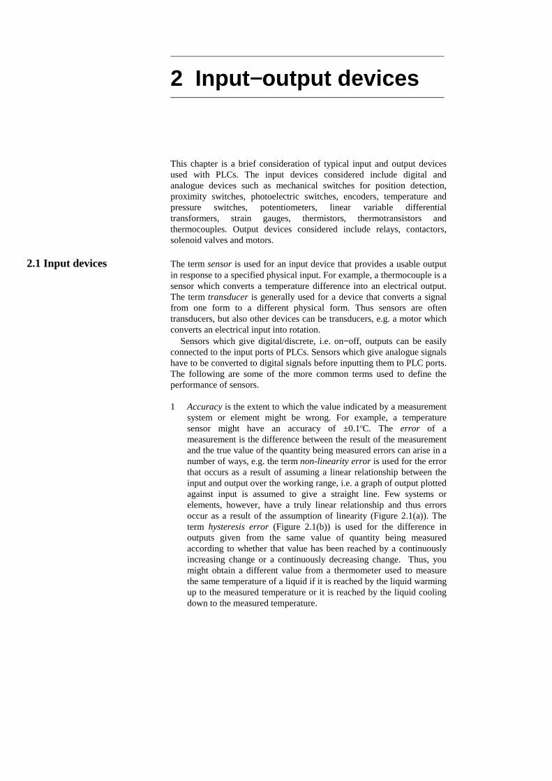
Sensors which give digital/discrete, i.e. on−off, outputs can be easilyconnected to the input ports of PLCs. Sensors which give analogue signalshave to be converted to digital signals before inputting them to PLC ports.The following are some of the more common terms used to define theperformance of sensors. 1 Accuracy is the extent to which the value indicated by a measurement
system or element might be wrong. For example, a temperaturesensor might have an accuracy of ±0.1oC. The error of ameasurement is the difference between the result of the measurementand the true value of the quantity being measured errors can arise in anumber of ways, e.g. the term non-linearity error is used for the errorthat occurs as a result of assuming a linear relationship between theinput and output over the working range, i.e. a graph of output plottedagainst input is assumed to give a straight line. Few systems orelements, however, have a truly linear relationship and thus errorsoccur as a result of the assumption of linearity (Figure 2.1(a)). Theterm hysteresis error (Figure 2.1(b)) is used for the difference inoutputs given from the same value of quantity being measuredaccording to whether that value has been reached by a continuouslyincreasing change or a continuously decreasing change. Thus, youmight obtain a different value from a thermometer used to measurethe same temperature of a liquid if it is reached by the liquid warmingup to the measured temperature or it is reached by the liquid coolingdown to the measured temperature.

Assumedrelationship
Actualrelationship
Non-linearityerror
True value
Mea
sure
d va
lue
(a) (b)
Increasing
Decreasing
Value being measured
Hysteresis error
Sen
sor o
utpu
t
Figure 2.1 Some sources of error: (a) non-linearity, (b) hysteresis
2 The range of variable of system is the limits between which the inputcan vary. For example, a resistance temperature sensor might bequoted as having a range of −200 to +800oC.
3 When the input value to a sensor changes, it will take some time toreach and settle down to the steady-state value (Figure 2.2). Theresponse time is the time which elapses after the input to a system orelement is abruptly increased from zero to a constant value up to thepoint at which the system or element gives an output corresponding tosome specified percentage, e.g. 95%, of the value of the input. Therise time is the time taken for the output to rise to some specifiedpercentage of the steady-state output. Often the rise time refers to thetime taken for the output to rise from 10% of the steady-state value to90 or 95% of the steady-state value. The settling time is the timetaken for the output to settle to within some percentage, e.g. 2%, ofthe steady-state value.
Steady-statereading
0 Time
Res
pons
e
Figure 2.2 Response of a sensor or measurement system to a suddeninput. You can easily see such a response when the current in anelectrical circuit is suddenly switched on and an ammeter readingobserved.
4 The sensitivity indicates how much the output of an instrumentsystem or system element changes when the quantity being measuredchanges by a given amount, i.e. the ratio ouput/input. For example, athermocouple might have a sensitivity of 20 µV/oC and so give anoutput of 20 µV for each 1ºC change in temperature.
18 Programmable Logic Controllers
5 The stability of a system is its ability to give the same output whenused to measure a constant input over a period of time. The term driftis often used to describe the change in output that occurs over time.The drift may be expressed as a percentage of the full range output.The term zero drift is used for the changes that occur in output whenthere is zero input.
6 The term repeatability is used for the ability of a measurement systemto give the same value for repeated measurements of the same valueof a variable. Common cause of lack of repeatability are randomfluctuations in the environment, e.g. changes in temperature andhumidity. The error arising from repeatability is usually expressed asa percentage of the full range output. For example, a pressure sensormight be quoted as having a repeatability of ±0.1% of full range.Thus with a range of 20 kPa this would be an error of ±20 Pa.
7 The reliability of a measurement system, or element in such a system,is defined as being the probability that it will operate to an agreedlevel of performance, for a specified period, subject to specifiedenvironmental conditions. The agreed level of performance might bethat the measurement system gives a particular accuracy.
The following are examples of some of the commonly used PLC inputdevices and their sensors.
2.1.1 Mechanical switches
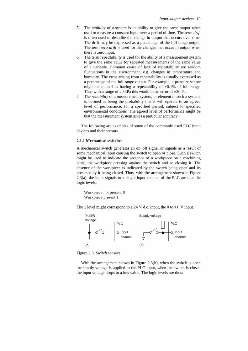
A mechanical switch generates an on−off signal or signals as a result ofsome mechanical input causing the switch to open or close. Such a switchmight be used to indicate the presence of a workpiece on a machiningtable, the workpiece pressing against the switch and so closing it. Theabsence of the workpiece is indicated by the switch being open and itspresence by it being closed. Thus, with the arrangement shown in Figure2.3(a), the input signals to a single input channel of the PLC are thus thelogic levels:
Workpiece not present 0Workpiece present 1
The 1 level might correspond to a 24 V d.c. input, the 0 to a 0 V input.
PLC
Inputchannel
Supplyvoltage
(a)
PLC
Inputchannel
Supply voltage
(b)
Figure 2.3 Switch sensors
With the arrangement shown in Figure 2.3(b), when the switch is openthe supply voltage is applied to the PLC input, when the switch is closedthe input voltage drops to a low value. The logic levels are thus:
Input–output devices 19

Workpiece not present 1Workpiece present 0
Switches are available with normally open (NO) or normally closed(NC) contacts or can be configured as either by choice of the relevantcontacts. An NO switch has its contacts open in the absence of amechanical input and the mechanical input is used to close the switch. AnNC switch has its contacts closed in the absence of a mechanical input andthe mechanical input is used to open the switch.
The term limit switch is used for a switch which is used to detect thepresence or passage of a moving part. It can be actuated by a cam, rolleror lever. Figure 2.4 shows some examples. The cam (Figure 2.4(c)) can berotated at a constant rate and so switch the switch on and off for particulartime intervals.
Button tooperateswitch(a)
Lever pushed down by contact
Button tooperateswitch
(b)
Roller pushed downby contact Button to
operateswitch
(c)
Rotating cam
Figure 2.4 Limit switches actuated by: (a) lever, (b) roller, (c) cam
2.1.2 Proximity switches
Proximity switches are used to detect the presence of an item withoutmaking contact with it. There are a number of forms of such switches,some being only suitable for metallic objects.
The eddy current type of proximity switch has a coil which is energisedby a constant alternating current and produces a constant alternatingmagnetic field. When a metallic object is close to it, eddy currents areinduced in it (Figure 2.5(a)). The magnetic field due to these eddycurrents induces an e.m.f. back in the coil with the result that the voltageamplitude needed to maintain the constant coil current changes. Thevoltage amplitude is thus a measure of the proximity of metallic objects.The voltage can be used to activate an electronic switch circuit, basicallya transistor which has its output switched from low to high by the voltagechange, and so give an on−off device. The range over which such objectscan be detected is typically about 0.5 to 20 mm.
Constantalternatingcurrent Metal object
Eddy currentAlternatingmagnetic field(a)
Magnet
Envelope Contacts
Springystrips
(b)
Sensor head
Object
The two platesof the capacitor(c)
Figure 2.5 Proximity switches: (a) eddy current, (b) reed switch, (c) capacitive
20 Programmable Logic Controllers

Another type is the reed switch. This consists of two overlapping, butnot touching, strips of a springy ferromagnetic material sealed in a glassor plastic envelope (Figure 2.5(b)). When a magnet or current-carryingcoil is brought close to the switch, the strips become magnetised andattract each other. The contacts then close. The magnet closes the contactswhen it is typically about 1 mm from the switch. Such a switch is widelyused with burglar alarms to detect when a door is opened; the magnetbeing in the door and the reed switch in the frame of the door. When thedoor opens the switch opens.
A proximity switch that can be used with metallic and non-metallicobjects is the capacitive proximity switch. The capacitance of a pair ofplates separated by some distance depends on the separation, the smallerthe separation the higher the capacitance. The sensor of the capacitiveproximity switch is just one of the plates of the capacitor, the other platebeing the metal object whose proximity is to be detected (Figure 2.5(c)).Thus the proximity of the object is detected by a change in capacitance.The sensor can also be used to detect non-metallic objects since thecapacitance of a capacitor depends on the dielectric between its plates. Inthis case the plates are the sensor and the earth and the non-metallic objectis the dielectric. The change in capacitance can be used to activate anelectronic switch circuit and so give an on−off device. Capacitiveproximity switches can be used to detect objects when they are typicallybetween 4 and 60 mm from the sensor head.
Another type, the inductive proximity switch, consists of a coil woundround a ferrous metallic core. When one end of this core is placed near toa ferrous metal object there is effectively a change in the amount ofmetallic core associated with the coil and so a change in its inductance.This change in inductance can be monitored using a resonant circuit, thepresence of the ferrous metal object thus changing the current in thatcircuit. The current can be used to activate an electronic switch circuit andso give an on−off device. The range over which such objects can bedetected is typically about 2 to 15 mm.
2.1.3 Photoelectric sensors and switches
Photoelectric switch devices can either operate as transmissive typeswhere the object being detected breaks a beam of light, usually infraredradiation, and stops it reaching the detector (Figure 2.6(a)) or reflectivetypes where the object being detected reflects a beam of light onto thedetector (Figure 2.6(b)). In both types the radiation emitter is generally alight-emitting diode (LED). The radiation detector might be a photo-transistor, often a pair of transistors, known as a Darlington pair. TheDarlington pair increases the sensitivity. Depending on the circuit used,the output can be made to switch to either high or low when light strikesthe transistor. Such sensors are supplied as packages for sensing thepresence of objects at close range, typically at less than about 5 mm.Figure 2.6(c) shows a U-shaped form where the object breaks the lightbeam.
Another possibility is a photodiode. Depending on the circuit used, theoutput can be made to switch to either high or low when light strikes thediode. Yet another possibility is a photoconductive cell. The resistance of
Input–output devices 21
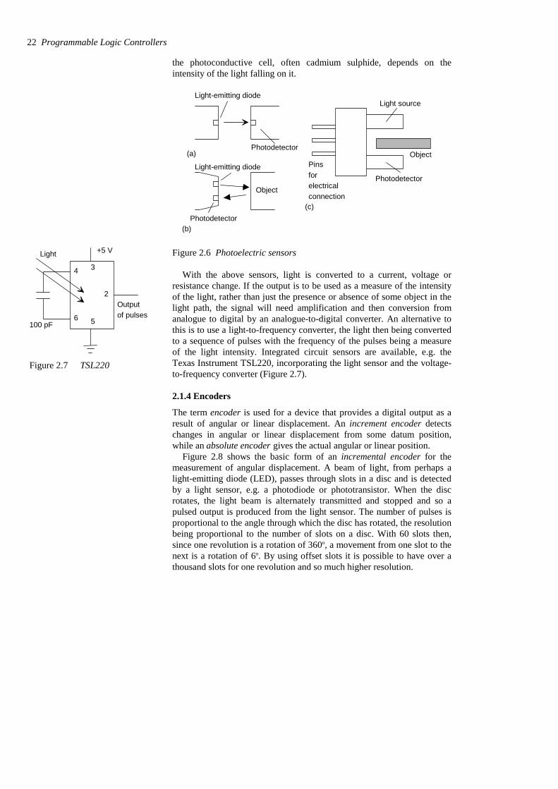
the photoconductive cell, often cadmium sulphide, depends on theintensity of the light falling on it.
Photodetector(a)
Light-emitting diode
Object
Photodetector
Light-emitting diode
(b)
Object
Light source
Photodetector
Pinsforelectrical connection
(c)
Figure 2.6 Photoelectric sensors
With the above sensors, light is converted to a current, voltage orresistance change. If the output is to be used as a measure of the intensityof the light, rather than just the presence or absence of some object in thelight path, the signal will need amplification and then conversion fromanalogue to digital by an analogue-to-digital converter. An alternative tothis is to use a light-to-frequency converter, the light then being convertedto a sequence of pulses with the frequency of the pulses being a measureof the light intensity. Integrated circuit sensors are available, e.g. theTexas Instrument TSL220, incorporating the light sensor and the voltage-to-frequency converter (Figure 2.7).
2.1.4 Encoders
The term encoder is used for a device that provides a digital output as aresult of angular or linear displacement. An increment encoder detectschanges in angular or linear displacement from some datum position,while an absolute encoder gives the actual angular or linear position.
Figure 2.8 shows the basic form of an incremental encoder for themeasurement of angular displacement. A beam of light, from perhaps alight-emitting diode (LED), passes through slots in a disc and is detectedby a light sensor, e.g. a photodiode or phototransistor. When the discrotates, the light beam is alternately transmitted and stopped and so apulsed output is produced from the light sensor. The number of pulses isproportional to the angle through which the disc has rotated, the resolutionbeing proportional to the number of slots on a disc. With 60 slots then,since one revolution is a rotation of 360o, a movement from one slot to thenext is a rotation of 6o. By using offset slots it is possible to have over athousand slots for one revolution and so much higher resolution.
22 Programmable Logic Controllers
+5 V
Outputof pulses
100 pF
4 3
2
6 5
Light
Figure 2.7 TSL220
Light
Detector
Rotating discFixeddisc
Apertures
Singleaperture
Figure 2.8 Basic form of an incremental encoder
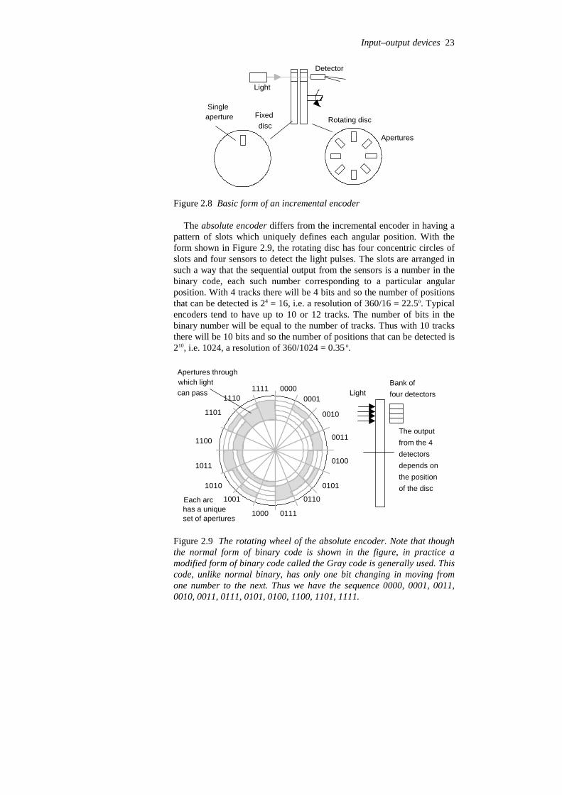
The absolute encoder differs from the incremental encoder in having apattern of slots which uniquely defines each angular position. With theform shown in Figure 2.9, the rotating disc has four concentric circles ofslots and four sensors to detect the light pulses. The slots are arranged insuch a way that the sequential output from the sensors is a number in thebinary code, each such number corresponding to a particular angularposition. With 4 tracks there will be 4 bits and so the number of positionsthat can be detected is 24 = 16, i.e. a resolution of 360/16 = 22.5o. Typicalencoders tend to have up to 10 or 12 tracks. The number of bits in thebinary number will be equal to the number of tracks. Thus with 10 tracksthere will be 10 bits and so the number of positions that can be detected is210, i.e. 1024, a resolution of 360/1024 = 0.35 o.
0001
0010
0011
0100
0101
0110
01111000
1001
1010
1011
1100
1101
11101111 0000 Light
Bank offour detectors
Apertures throughwhich lightcan pass
Each archas a uniqueset of apertures
The outputfrom the 4detectorsdepends onthe positionof the disc
Figure 2.9 The rotating wheel of the absolute encoder. Note that thoughthe normal form of binary code is shown in the figure, in practice amodified form of binary code called the Gray code is generally used. Thiscode, unlike normal binary, has only one bit changing in moving fromone number to the next. Thus we have the sequence 0000, 0001, 0011,0010, 0011, 0111, 0101, 0100, 1100, 1101, 1111.
Input–output devices 23
2.1.5 Temperature sensors
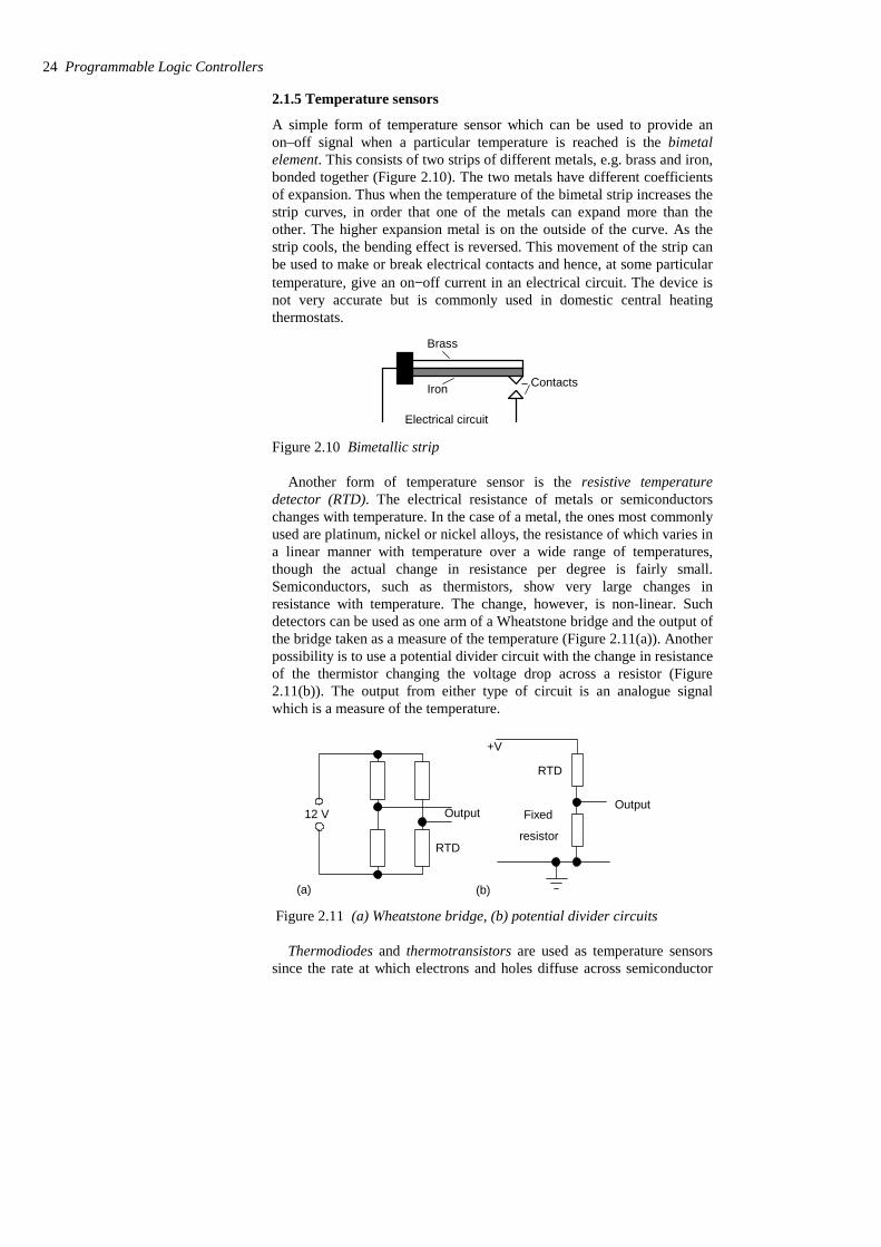
A simple form of temperature sensor which can be used to provide anon–off signal when a particular temperature is reached is the bimetalelement. This consists of two strips of different metals, e.g. brass and iron,bonded together (Figure 2.10). The two metals have different coefficientsof expansion. Thus when the temperature of the bimetal strip increases thestrip curves, in order that one of the metals can expand more than theother. The higher expansion metal is on the outside of the curve. As thestrip cools, the bending effect is reversed. This movement of the strip canbe used to make or break electrical contacts and hence, at some particulartemperature, give an on−off current in an electrical circuit. The device isnot very accurate but is commonly used in domestic central heatingthermostats.
Brass
Iron
Electrical circuit
Contacts
Figure 2.10 Bimetallic strip
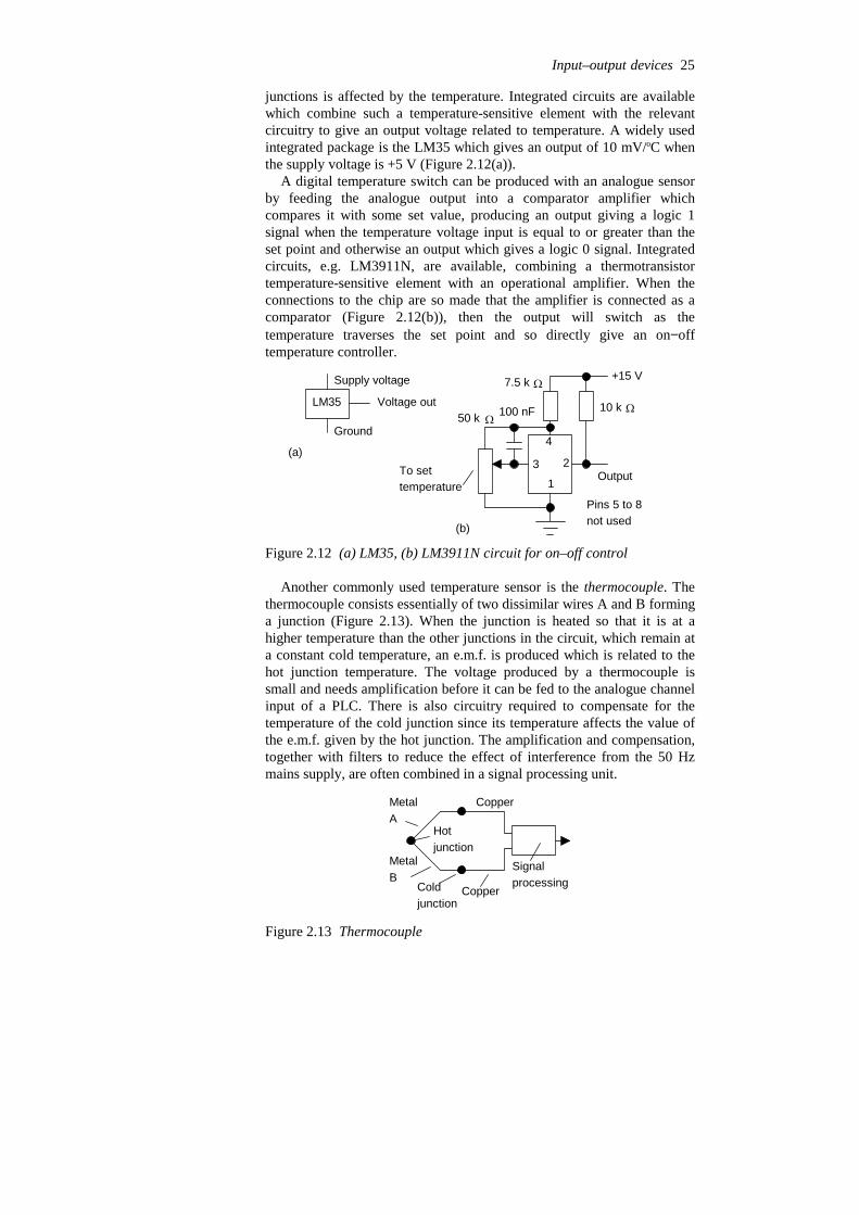
Another form of temperature sensor is the resistive temperaturedetector (RTD). The electrical resistance of metals or semiconductorschanges with temperature. In the case of a metal, the ones most commonlyused are platinum, nickel or nickel alloys, the resistance of which varies ina linear manner with temperature over a wide range of temperatures,though the actual change in resistance per degree is fairly small.Semiconductors, such as thermistors, show very large changes inresistance with temperature. The change, however, is non-linear. Suchdetectors can be used as one arm of a Wheatstone bridge and the output ofthe bridge taken as a measure of the temperature (Figure 2.11(a)). Anotherpossibility is to use a potential divider circuit with the change in resistanceof the thermistor changing the voltage drop across a resistor (Figure2.11(b)). The output from either type of circuit is an analogue signalwhich is a measure of the temperature.
12 V
RTD
Output
(a)
RTD
Output
(b)
Fixed
resistor
+V
Figure 2.11 (a) Wheatstone bridge, (b) potential divider circuits
Thermodiodes and thermotransistors are used as temperature sensorssince the rate at which electrons and holes diffuse across semiconductor
24 Programmable Logic Controllers
junctions is affected by the temperature. Integrated circuits are availablewhich combine such a temperature-sensitive element with the relevantcircuitry to give an output voltage related to temperature. A widely usedintegrated package is the LM35 which gives an output of 10 mV/oC whenthe supply voltage is +5 V (Figure 2.12(a)).
A digital temperature switch can be produced with an analogue sensorby feeding the analogue output into a comparator amplifier whichcompares it with some set value, producing an output giving a logic 1signal when the temperature voltage input is equal to or greater than theset point and otherwise an output which gives a logic 0 signal. Integratedcircuits, e.g. LM3911N, are available, combining a thermotransistortemperature-sensitive element with an operational amplifier. When theconnections to the chip are so made that the amplifier is connected as acomparator (Figure 2.12(b)), then the output will switch as thetemperature traverses the set point and so directly give an on−offtemperature controller.
LM35
Supply voltage
Ground
Voltage out
(a)3
4
2
1To settemperature
Output
+15 V
Pins 5 to 8not used
10 k50 k 100 nF
7.5 k
(b)
Figure 2.12 (a) LM35, (b) LM3911N circuit for on–off control
Another commonly used temperature sensor is the thermocouple. Thethermocouple consists essentially of two dissimilar wires A and B forminga junction (Figure 2.13). When the junction is heated so that it is at ahigher temperature than the other junctions in the circuit, which remain ata constant cold temperature, an e.m.f. is produced which is related to thehot junction temperature. The voltage produced by a thermocouple issmall and needs amplification before it can be fed to the analogue channelinput of a PLC. There is also circuitry required to compensate for thetemperature of the cold junction since its temperature affects the value ofthe e.m.f. given by the hot junction. The amplification and compensation,together with filters to reduce the effect of interference from the 50 Hzmains supply, are often combined in a signal processing unit.
MetalA
MetalB
Copper
Copper
Signalprocessing
Hotjunction
Coldjunction
Figure 2.13 Thermocouple
Input–output devices 25

2.1.6 Position/displacement sensors
The term position sensor is used for a sensor that gives a measure of thedistance between a reference point and the current location of the target, adisplacement sensor being one that gives a measure of the distancebetween the present position of the target and the previously recordedposition.
Resistive linear and angular position sensors are widely used andrelatively inexpensive. These are also called linear and rotarypotentiometers. A d.c. voltage is provided across the full length of thetrack and the voltage signal between a contact which slides over theresistance track and one end of the track is related to the position of thesliding contact between the ends of the potentiometer resistance track(Figure 2.14). The potentiometer thus provides an analogue linear orangular position sensor.
Another form of displacement sensor is the linear variable differentialtransformer (LVDT), this giving a voltage output related to the position ofa ferrous rod. The LVDT consists of three symmetrically placed coilsthrough which the ferrous rod moves (Figure 2.15).
Constanta.c. voltage
Outputvoltage
Primary
Secondary 1
Secondary 2
Ferrous rod
Displacement
Constanta.c.voltage
v
v
1
2
v – v1 2
Figure 2.15 LVDT
When an alternating current is applied to the primary coil, alternatingvoltages, v1 and v2, are induced in the two secondary coils. When theferrous rod core is centred between the two secondary coils, the voltagesinduced in them are equal. The outputs from the two secondary coils areconnected so that their combined output is the difference between the twovoltages, i.e. v1 – v2. With the rod central, the two alternating voltages areequal and so there is no output voltage. When the rod is displaced from itscentral position there is more of the rod in one secondary coil than theother. As a result the size of the alternating voltage induced in one coil isgreater than that in the other. The difference between the two secondarycoil voltages, i.e. the output, thus depends on the position of the ferrousrod. The output from the LVDT is an alternating voltage. This is usuallyconverted to an analogue d.c. voltage and amplified before inputting tothe analogue channel of a PLC.
Capacitive displacement sensors are essentially just parallel platecapacitors. The capacitance will change if the plate separation changes,the area of overlap of the plates changes, or a slab of dielectric is movedinto or out of the plates (Figure 2.16). All these methods can be used togive linear displacement sensors. The change in capacitance has to beconverted into a suitable electrical signal by signal conditioning.
26 Programmable Logic Controllers
+V
0
Outputvoltage
Figure 2.14 Potentiometer
Figure 2.16 Capacitor sensors:
(a) (b) (c)
(a) changing the plate separation,(b) changing the area of overlap,(c) moving the dielectric
2.1.7 Strain gauges
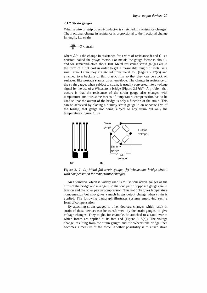
When a wire or strip of semiconductor is stretched, its resistance changes.The fractional change in resistance is proportional to the fractional changein length, i.e. strain.
RR = G % strain
where ∆R is the change in resistance for a wire of resistance R and G is aconstant called the gauge factor. For metals the gauge factor is about 2and for semiconductors about 100. Metal resistance strain gauges are inthe form of a flat coil in order to get a reasonable length of metal in asmall area. Often they are etched from metal foil (Figure 2.17(a)) andattached to a backing of thin plastic film so that they can be stuck onsurfaces, like postage stamps on an envelope. The change in resistance ofthe strain gauge, when subject to strain, is usually converted into a voltagesignal by the use of a Wheatstone bridge (Figure 2.17(b)). A problem thatoccurs is that the resistance of the strain gauge also changes withtemperature and thus some means of temperature compensation has to beused so that the output of the bridge is only a function of the strain. Thiscan be achieved by placing a dummy strain gauge in an opposite arm ofthe bridge, that gauge not being subject to any strain but only thetemperature (Figure 2.18).
(a) (b)
d.c.voltage
Outputvoltage
Straingauge
Dummygauge
Figure 2.17 (a) Metal foil strain gauge, (b) Wheatstone bridge circuitwith compensation for temperature changes
An alternative which is widely used is to use four active gauges as thearms of the bridge and arrange it so that one pair of opposite gauges are intension and the other pair in compression. This not only gives temperaturecompensation but also gives a much larger output change when strain isapplied. The following paragraph illustrates systems employing such aform of compensation.
By attaching strain gauges to other devices, changes which result instrain of those devices can be transformed, by the strain gauges, to givevoltage changes. They might, for example, be attached to a cantilever towhich forces are applied at its free end (Figure 2.18(a)). The voltagechange, resulting from the strain gauges and the Wheatstone bridge, thenbecomes a measure of the force. Another possibility is to attach strain
Input–output devices 27

gauges to a diaphragm which deforms as a result of pressure (Figure2.18(b)). The output from the gauges, and associated Wheatstone bridge,then becomes a measure of the pressure.
d.c.voltage
Outputvoltage
1 2
4 3
Force
Cantilever4 strain gauges,upper surface extendedand increase in resistance,lower surface compressedand decrease in resistance
1 3
2 4
(a)
d.c.voltage
Outputvoltage
1 2
4 3
Applied pressure
4 strain gauges, 2 for radialstrain, 2 for circumferential strain
1 2/3 4
(b)
Figure 2.18 Strain gauges used for (a) force sensor, (b) pressure sensor
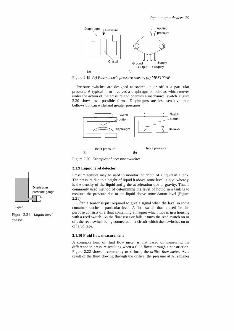
2.1.8 Pressure sensors
Commonly used pressure sensors which give responses related to thepressure are diaphragm and bellows types. The diaphragm type consists ofa thin disc of metal or plastic, secured round its edges. When there is apressure difference between the two sides of the diaphragm, the centre ofit deflects. The amount of deflection is related to the pressure difference.This deflection may be detected by strain gauges attached to thediaphragm (see Figure 2.18(b)), by a change in capacitance between it anda parallel fixed plate or by using the deflection to squeeze a piezoelectriccrystal (Figure 2.19(a)). When a piezoelectric crystal is squeezed, there isa relative displacement of positive and negative charges within the crystaland the outer surfaces of the crystal become charged. Hence a potentialdifference appears across it. An example of such a sensor is the MotorolaMPX100AP sensor (Figure 2.19(b)). This has a built-in vacuum on oneside of the diaphragm and so the deflection of the diaphragm gives ameasure of the absolute pressure applied to the other side of thediaphragm. The output is a voltage which is proportional to the appliedpressure with a sensitivity of 0.6 mV/kPa. Other versions are availablewhich have one side of the diaphragm open to the atmosphere and so canbe used to measure gauge pressure; others allow pressures to be applied toboth sides of the diaphragm and so can be used to measure differentialpressures.
28 Programmable Logic Controllers
Pressure
Crystal
Diaphragm
Ground – Supply+ Supply+ Output
Appliedpressure
(a) (b)
Figure 2.19 (a) Piezoelectric pressure sensor, (b) MPX100AP
Pressure switches are designed to switch on or off at a particularpressure. A typical form involves a diaphragm or bellows which movesunder the action of the pressure and operates a mechanical switch. Figure2.20 shows two possible forms. Diaphragms are less sensitive thanbellows but can withstand greater pressures.
Diaphragm
Switchbutton
Input pressure(a)
Switchbutton
Input pressure
Bellows
(b)
Figure 2.20 Examples of pressure switches
2.1.9 Liquid level detector
Pressure sensors may be used to monitor the depth of a liquid in a tank.The pressure due to a height of liquid h above some level is hρg, where ρis the density of the liquid and g the acceleration due to gravity. Thus acommonly used method of determining the level of liquid in a tank is tomeasure the pressure due to the liquid above some datum level (Figure2.21).
Often a sensor is just required to give a signal when the level in somecontainer reaches a particular level. A float switch that is used for thispurpose consists of a float containing a magnet which moves in a housingwith a reed switch. As the float rises or falls it turns the reed switch on oroff, the reed switch being connected in a circuit which then switches on oroff a voltage.
2.1.10 Fluid flow measurement
A common form of fluid flow meter is that based on measuring thedifference in pressure resulting when a fluid flows through a constriction.Figure 2.22 shows a commonly used form, the orifice flow meter. As aresult of the fluid flowing through the orifice, the pressure at A is higher
Input–output devices 29
Diaphragmpressure gauge
Liquid
Figure 2.21 Liquid levelsensor
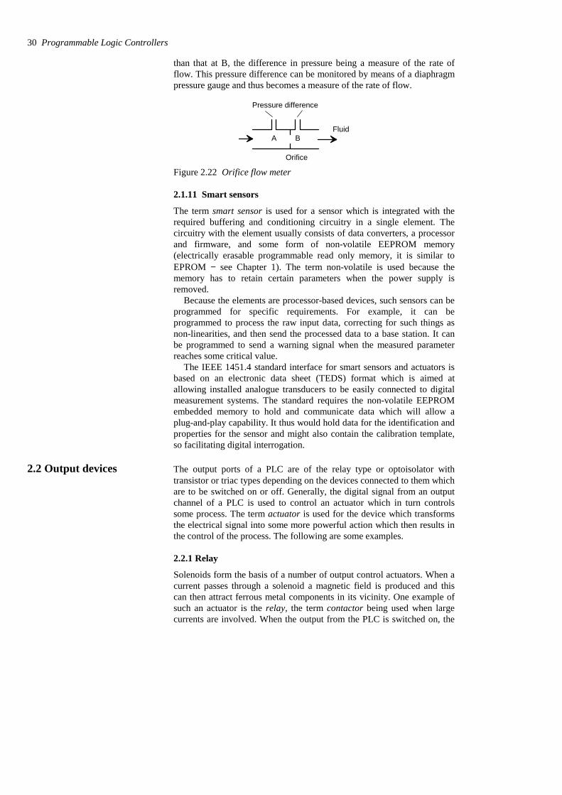
than that at B, the difference in pressure being a measure of the rate offlow. This pressure difference can be monitored by means of a diaphragmpressure gauge and thus becomes a measure of the rate of flow.
A B
Orifice
Fluid
Pressure difference
Figure 2.22 Orifice flow meter
2.1.11 Smart sensors
The term smart sensor is used for a sensor which is integrated with therequired buffering and conditioning circuitry in a single element. Thecircuitry with the element usually consists of data converters, a processorand firmware, and some form of non-volatile EEPROM memory(electrically erasable programmable read only memory, it is similar toEPROM − see Chapter 1). The term non-volatile is used because thememory has to retain certain parameters when the power supply isremoved.
Because the elements are processor-based devices, such sensors can beprogrammed for specific requirements. For example, it can beprogrammed to process the raw input data, correcting for such things asnon-linearities, and then send the processed data to a base station. It canbe programmed to send a warning signal when the measured parameterreaches some critical value.
The IEEE 1451.4 standard interface for smart sensors and actuators isbased on an electronic data sheet (TEDS) format which is aimed atallowing installed analogue transducers to be easily connected to digitalmeasurement systems. The standard requires the non-volatile EEPROMembedded memory to hold and communicate data which will allow aplug-and-play capability. It thus would hold data for the identification andproperties for the sensor and might also contain the calibration template,so facilitating digital interrogation.
2.2 Output devices The output ports of a PLC are of the relay type or optoisolator withtransistor or triac types depending on the devices connected to them whichare to be switched on or off. Generally, the digital signal from an outputchannel of a PLC is used to control an actuator which in turn controlssome process. The term actuator is used for the device which transformsthe electrical signal into some more powerful action which then results inthe control of the process. The following are some examples.
2.2.1 Relay
Solenoids form the basis of a number of output control actuators. When acurrent passes through a solenoid a magnetic field is produced and thiscan then attract ferrous metal components in its vicinity. One example ofsuch an actuator is the relay, the term contactor being used when largecurrents are involved. When the output from the PLC is switched on, the
30 Programmable Logic Controllers
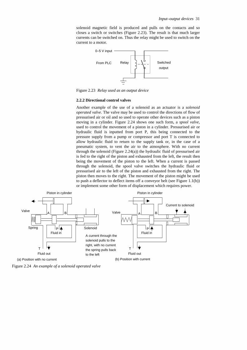
solenoid magnetic field is produced and pulls on the contacts and socloses a switch or switches (Figure 2.23). The result is that much largercurrents can be switched on. Thus the relay might be used to switch on thecurrent to a motor.
From PLC Switched output
Relay
0–5 V input
Figure 2.23 Relay used as an output device
2.2.2 Directional control valves
Another example of the use of a solenoid as an actuator is a solenoidoperated valve. The valve may be used to control the directions of flow ofpressurised air or oil and so used to operate other devices such as a pistonmoving in a cylinder. Figure 2.24 shows one such form, a spool valve,used to control the movement of a piston in a cylinder. Pressurised air orhydraulic fluid is inputted from port P, this being connected to thepressure supply from a pump or compressor and port T is connected toallow hydraulic fluid to return to the supply tank or, in the case of apneumatic system, to vent the air to the atmosphere. With no currentthrough the solenoid (Figure 2.24(a)) the hydraulic fluid of pressurised airis fed to the right of the piston and exhausted from the left, the result thenbeing the movement of the piston to the left. When a current is passedthrough the solenoid, the spool valve switches the hydraulic fluid orpressurised air to the left of the piston and exhausted from the right. Thepiston then moves to the right. The movement of the piston might be usedto push a deflector to deflect items off a conveyor belt (see Figure 1.1(b))or implement some other form of displacement which requires power.
T
A B
Piston in cylinder
PFluid in
Fluid out
Valve
A current through thesolenoid pulls to theright, with no currentthe spring pulls back to the left
Current to solenoid
T
A B
Piston in cylinder
PFluid in
Fluid out
Valve
Solenoid
(a) Position with no current (b) Position with current
Spring
Figure 2.24 An example of a solenoid operated valve
Input–output devices 31
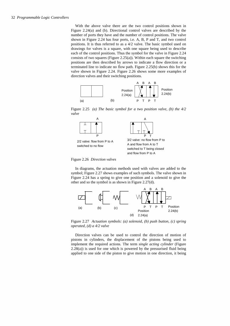
With the above valve there are the two control positions shown inFigure 2.24(a) and (b). Directional control valves are described by thenumber of ports they have and the number of control positions. The valveshown in Figure 2.24 has four ports, i.e. A, B, P and T, and two controlpositions. It is thus referred to as a 4/2 valve. The basic symbol used ondrawings for valves is a square, with one square being used to describeeach of the control positions. Thus the symbol for the valve in Figure 2.24consists of two squares (Figure 2.25(a)). Within each square the switchingpositions are then described by arrows to indicate a flow direction or aterminated line to indicate no flow path. Figure 2.25(b) shows this for thevalve shown in Figure 2.24. Figure 2.26 shows some more examples ofdirection valves and their switching positions.
(a)
A B A B
P T P T
Position2.24(b)
Position2.24(a)
(b)
Figure 2.25 (a) The basic symbol for a two position valve, (b) the 4/2valve
P
A
2/2 valve: flow from P to Aswitched to no flow
P T
A
3/2 valve: no flow from P to A and flow from A to Tswitched to T being closedand flow from P to A
Figure 2.26 Direction valves
In diagrams, the actuation methods used with valves are added to thesymbol; Figure 2.27 shows examples of such symbols. The valve shown inFigure 2.24 has a spring to give one position and a solenoid to give theother and so the symbol is as shown in Figure 2.27(d).
(a) (b) (c)
A B A B
P T P T Position2.24(b)Position
2.24(a)(d)
Figure 2.27 Actuation symbols: (a) solenoid, (b) push button, (c) springoperated, (d) a 4/2 valve
Direction valves can be used to control the direction of motion ofpistons in cylinders, the displacement of the pistons being used toimplement the required actions. The term single acting cylinder (Figure2.28(a)) is used for one which is powered by the pressurised fluid beingapplied to one side of the piston to give motion in one direction, it being
32 Programmable Logic Controllers

returned in the other direction by possibly an internal spring. The termdouble acting cylinder (Figure 2.28(b)) is used when the cylinder ispowered by fluid for its motion in both piston movement directions.Figure 2.29 shows how a valve can be used to control the direction ofmotion of a piston in a single-acting cylinder; Figure 2.30 shows how twovalves can be used to control the action of a piston in a double actingcylinder.
Input Exhaust
(a) (b)
Input/exhaust Input/exhaust
Figure 2.28 Cylinders: (a) single acting, (b) double acting
Cylinder in retracted position Current to solenoid cylinder extends
Solenoid current switched offcylinder retracts
Vent symbol
Pressuresource symbol
Figure 2.29 Control of a single-acting cylinder
Input–output devices 33
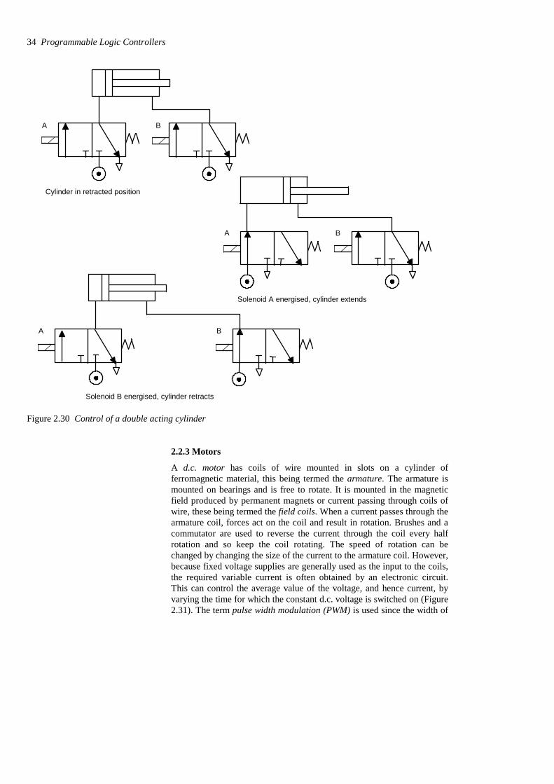
Cylinder in retracted position
A B
Solenoid A energised, cylinder extends
A B
Solenoid B energised, cylinder retracts
A B
Figure 2.30 Control of a double acting cylinder
2.2.3 Motors
A d.c. motor has coils of wire mounted in slots on a cylinder offerromagnetic material, this being termed the armature. The armature ismounted on bearings and is free to rotate. It is mounted in the magneticfield produced by permanent magnets or current passing through coils ofwire, these being termed the field coils. When a current passes through thearmature coil, forces act on the coil and result in rotation. Brushes and acommutator are used to reverse the current through the coil every halfrotation and so keep the coil rotating. The speed of rotation can bechanged by changing the size of the current to the armature coil. However,because fixed voltage supplies are generally used as the input to the coils,the required variable current is often obtained by an electronic circuit.This can control the average value of the voltage, and hence current, byvarying the time for which the constant d.c. voltage is switched on (Figure2.31). The term pulse width modulation (PWM) is used since the width of
34 Programmable Logic Controllers

the voltage pulses is used to control the average d.c. voltage applied to thearmature. A PLC might thus control the speed of rotation of a motor bycontrolling the electronic circuit used to control the width of the voltagepulses.
Vol
tage
Time
Average voltage
Vol
tage
Time
Average voltage
Figure 2.31 Pulse width modulation
Many industrial processes only require the PLC to switch a d.c. motoron or off. This might be done using a relay. Figure 2.32(a) shows the basicprinciple. The diode is included to dissipate the induced current resultingfrom the back e.m.f. Sometimes a PLC is required to reverse the directionof rotation of the motor. This can be done using relays to reverse thedirection of the current applied to the armature coil. Figure 2.32(b) showsthe basic principle. For rotation in one direction, switch 1 is closed andswitch 2 opened. For rotation in the other direction, switch 1 is openedand switch 2 closed.
Switchcontrolledby PLC
+V
0 V
Motor
1
2
+V
0 V
(a)(b)
Figure 2.32 D.c. motor: (a) on–off control, (b) directional control
Another form of d.c. motor is the brushless d.c. motor. This uses apermanent magnet for the magnetic field but, instead of the armature coilrotating as a result of the magnetic field of the magnet, the permanentmagnet rotates within the stationary coil. With the conventional d.c.motor, a commutator has to be used to reverse the current through the coilevery half rotation in order to keep the coil rotating in the same direction.With the brushless permanent magnet motor, electronic circuitry is used toreverse the current. The motor can be started and stopped by controllingthe current to the stationary coil. To reverse the motor, reversing thecurrent is not so easy because of the electronic circuitry used for thecommutator function. One method that is used is to incorporate sensorswith the motor to detect the position of the north and south poles. These
Input–output devices 35
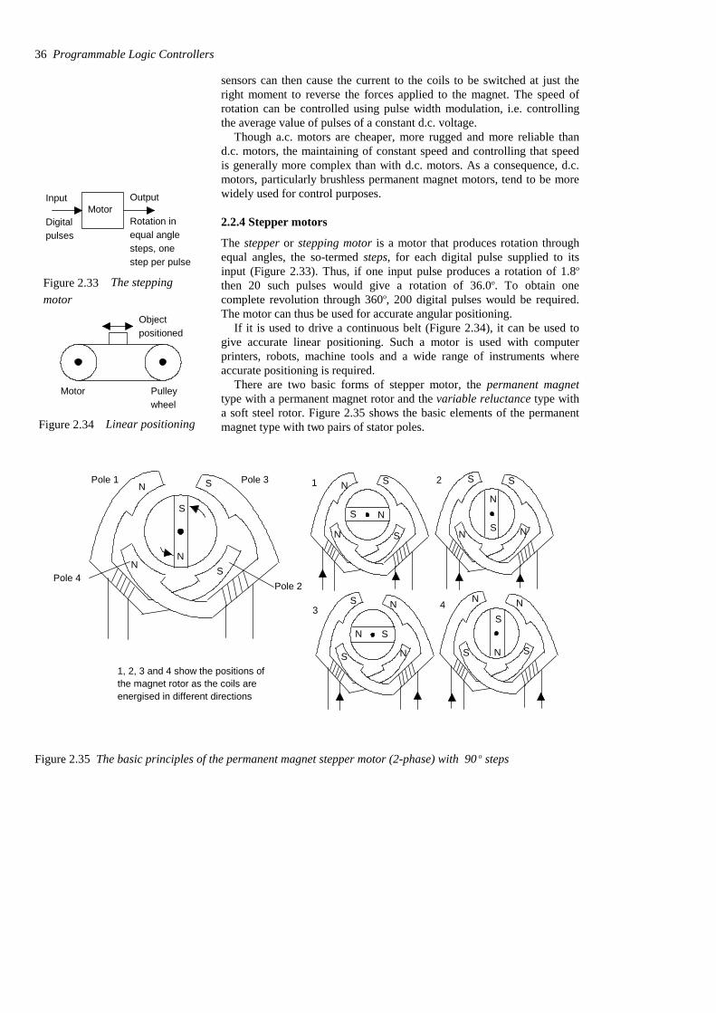
sensors can then cause the current to the coils to be switched at just theright moment to reverse the forces applied to the magnet. The speed ofrotation can be controlled using pulse width modulation, i.e. controllingthe average value of pulses of a constant d.c. voltage.
Though a.c. motors are cheaper, more rugged and more reliable thand.c. motors, the maintaining of constant speed and controlling that speedis generally more complex than with d.c. motors. As a consequence, d.c.motors, particularly brushless permanent magnet motors, tend to be morewidely used for control purposes.
2.2.4 Stepper motors
The stepper or stepping motor is a motor that produces rotation throughequal angles, the so-termed steps, for each digital pulse supplied to itsinput (Figure 2.33). Thus, if one input pulse produces a rotation of 1.8o
then 20 such pulses would give a rotation of 36.0o. To obtain onecomplete revolution through 360o, 200 digital pulses would be required.The motor can thus be used for accurate angular positioning.
If it is used to drive a continuous belt (Figure 2.34), it can be used togive accurate linear positioning. Such a motor is used with computerprinters, robots, machine tools and a wide range of instruments whereaccurate positioning is required.
There are two basic forms of stepper motor, the permanent magnettype with a permanent magnet rotor and the variable reluctance type witha soft steel rotor. Figure 2.35 shows the basic elements of the permanentmagnet type with two pairs of stator poles.
S
S
N
N
Pole 1 Pole 3
Pole 4Pole 2
S
N
S
S
N
N
S N
S S
N NS
S
S N
N
SN
SS
N NS
N
N
1 2
3 4
1, 2, 3 and 4 show the positions ofthe magnet rotor as the coils areenergised in different directions
Figure 2.35 The basic principles of the permanent magnet stepper motor (2-phase) with 90 o steps
36 Programmable Logic Controllers
MotorInput Output
Digitalpulses
Rotation inequal anglesteps, onestep per pulse
Figure 2.33 The steppingmotor
Motor Pulleywheel
Objectpositioned
Figure 2.34 Linear positioning

Each pole is activated by a current being passed through theappropriate field winding, the coils being such that opposite poles areproduced on opposite coils. The current is supplied from a d.c. source tothe windings through switches. With the currents switched through thecoils such that the poles are as shown in Figure 2.35, the rotor will moveto line up with the next pair of poles and stop there. This would be, forFigure 6.35, an angle of 45o. If the current is then switched so that thepolarities are reversed, the rotor will move a step to line up with the nextpair of poles, at angle 135o and stop there. The polarities associated witheach step are:
Repeat of steps 1 to 45
SouthNorthSouth North 4 SouthNorth North South 3 NorthSouthNorthSouth2 NorthSouthSouthNorth1
Pole 4Pole 3Pole 2Pole 1Step
There are thus, in this case, four possible rotor positions: 45o, 135o, 225o
and 315o.Figure 2.36 shows the basic principle of the variable reluctance type.
The rotor is made of soft steel and has a number of teeth, the numberbeing less than the number of poles on the stator. The stator has pairs ofpoles, each pair of poles being activated and made into an electromagnetby a current being passed through the coils wrapped round them. Whenone pair of poles is activated, a magnetic field is produced which attractsthe nearest pair of rotor teeth so that the teeth and poles line up. This istermed the position of minimum reluctance. By then switching the currentto the next pair of poles, the rotor can be made to rotate to line up withthose poles. Thus by sequentially switching the current from one pair ofpoles to the next, the rotor can be made to rotate in steps.
N
S
This pair of polesenergised by currentbeing switched to them
StatorRotor
Figure 2.36 The principle of the variable reluctance stepper motor
There is another version of the stepper motor and that is a hybridstepper. This combines features of both the permanent magnet andvariable reluctance motors. They have a permanent magnet rotor encased
Input–output devices 37
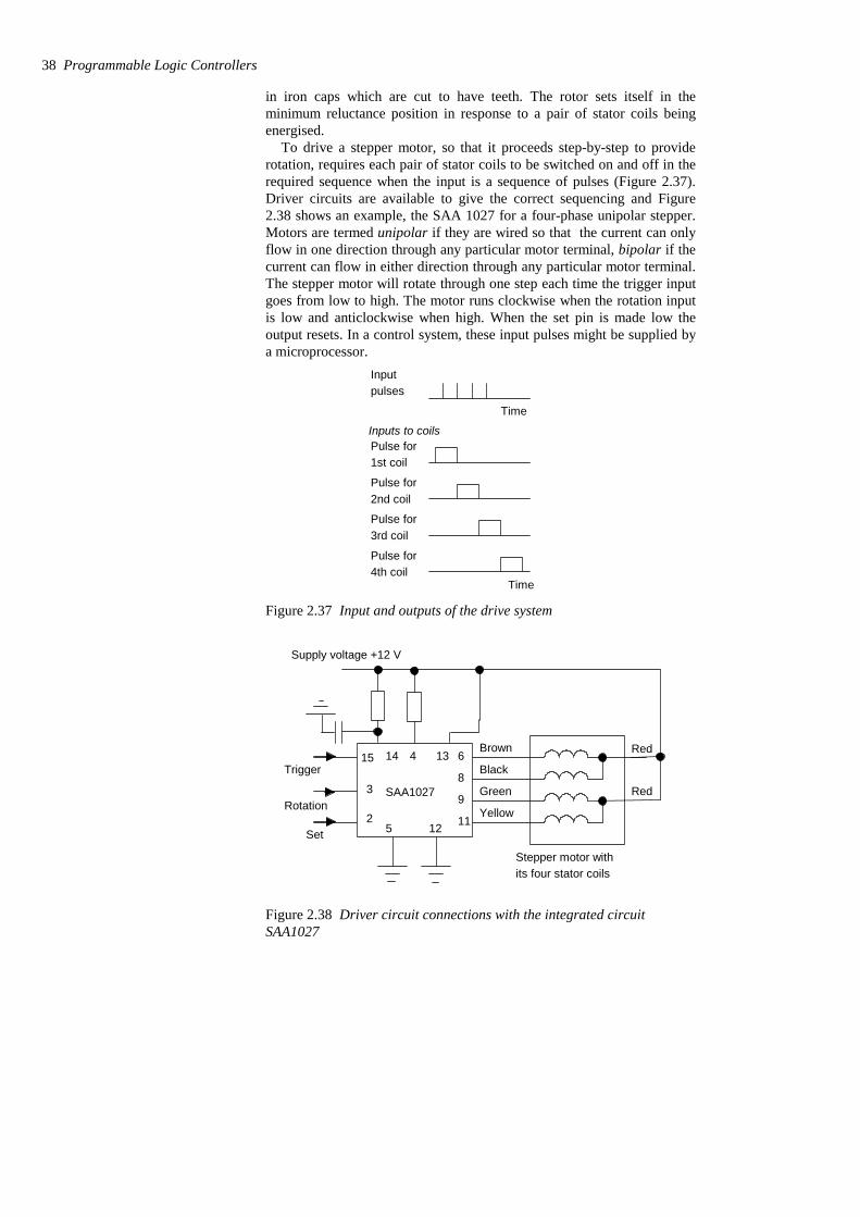
in iron caps which are cut to have teeth. The rotor sets itself in theminimum reluctance position in response to a pair of stator coils beingenergised.
To drive a stepper motor, so that it proceeds step-by-step to providerotation, requires each pair of stator coils to be switched on and off in therequired sequence when the input is a sequence of pulses (Figure 2.37).Driver circuits are available to give the correct sequencing and Figure2.38 shows an example, the SAA 1027 for a four-phase unipolar stepper.Motors are termed unipolar if they are wired so that the current can onlyflow in one direction through any particular motor terminal, bipolar if thecurrent can flow in either direction through any particular motor terminal.The stepper motor will rotate through one step each time the trigger inputgoes from low to high. The motor runs clockwise when the rotation inputis low and anticlockwise when high. When the set pin is made low theoutput resets. In a control system, these input pulses might be supplied bya microprocessor.
Time
Input pulses
Pulse for1st coil
Pulse for2nd coil
Pulse for3rd coil
Pulse for4th coil
Time
Inputs to coils
Figure 2.37 Input and outputs of the drive system
5 12
6
8
9
11
15
3
2
14 4 13
SAA1027
Stepper motor withits four stator coils
Supply voltage +12 V
Set
Rotation
Trigger
Brown
Black
Green
Yellow
Red
Red
Figure 2.38 Driver circuit connections with the integrated circuitSAA1027
38 Programmable Logic Controllers

2.3 Examples of applications The following are some examples of control systems designed to illustratethe use of a range of input and output devices.
2.3.1 A conveyor belt
Consider a conveyor belt that is to be used to transport goods from aloading machine to a packaging area (Figure 2.39). When an item isloaded onto the conveyor belt, a contact switch might be used to indicatethat the item is on the belt and start the conveyor motor. The motor thenhas to keep running until the item reaches the far end of the conveyor andfalls off into the packaging area. When it does this, a switch might beactivated which has the effect of switching off the conveyor motor. Themotor is then to remain off until the next item is loaded onto the belt.Thus the inputs to a PLC controlling the conveyor are from two switchesand the output is to a motor.
Loading
Packaging
Switch Switch
Figure 2.39 Conveyor
2.3.2 A lift
Consider a simple goods lift to move items from one level to another. Itmight be bricks from the ground level to the height where the bricklayersare working. The lift is to move upwards when a push button is pressed atthe ground level to send the lift upwards or a push button is pressed at theupper level to request the lift to move upwards, but in both cases there is acondition that has to be met that a limit switch indicates that the accessgate to the lift platform is closed. The lift is to move downwards when apush button is pressed at the upper level to send the lift downwards or apush button is pressed at the lower level to request the lift to movedownwards, but in both cases there is a condition that has to be met that alimit switch indicates that the access gate to the lift platform is closed.Thus the inputs to the control system are electrical on−off signals frompush button switches and limit switches. The output from the controlsystem is the signal to control the motor.
2.3.3 A robot control system
Figure 6.40 shows how directional control valves can be used for acontrol system of a robot. When there is an input to solenoid A of valve 1,the piston moves to the right and causes the gripper to close. If solenoid Bis energised, with A de-energised, the piston moves to the left and thegripper opens. When both solenoids are de-energised, no air passes toeither side of the piston in the cylinder and the piston keeps its positionwithout change. Likewise, inputs to the solenoids of valve 2 are used toextend or retract the arm. Inputs to the solenoids of valve 3 are used to
Input–output devices 39
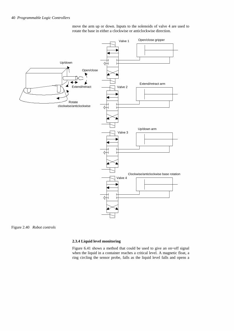
move the arm up or down. Inputs to the solenoids of valve 4 are used torotate the base in either a clockwise or anticlockwise direction.
Open/close gripperValve 1
Extend/retract armValve 2
Up/down armValve 3
Clockwise/anticlockwise base rotationValve 4
Extend/retract
Open/close
Up/down
Rotateclockwise/anticlockwise
Figure 2.40 Robot controls
2.3.4 Liquid level monitoring
Figure 6.41 shows a method that could be used to give an on−off signalwhen the liquid in a container reaches a critical level. A magnetic float, aring circling the sensor probe, falls as the liquid level falls and opens a
40 Programmable Logic Controllers

reed switch when the critical level is reached. The reed switch is in serieswith a 39 resistor so that this is switched in parallel with a 1 k resistorby the action of the reed switch. Opening the reed switch thus increasesthe resistance from about 37 to 1 k. Such a resistance change can betransformed by signal conditioning to give suitable on–off signals.
Magnetic floatFloat stop 39
1 k
Reed switch
Liquid
Sensor probe
Figure 2.41 Liquid level monitoring
Problems Questions 1 to 10 have four answer options: A, B, C or D. Choose thecorrect answer from the answer options.
1 Decide whether each of these statements is True (T) or False (F).
A limit switch:(i) Can be used to detect the presence of a moving part.(ii) Is activated by contacts making or breaking an electrical circuit.
A (i) T (ii) TB (i) T (ii) FC (i) F (ii) TD (i) F (ii) F
2 Decide whether each of these statements is True (T) or False (F).
A thermistor is a temperature sensor which gives resistance changeswhich are:(i) A non-linear function of temperature.(ii) Large for comparatively small temperature changes.
Input–output devices 41

A (i) T (ii) TB (i) T (ii) FC (i) F (ii) TD (i) F (ii) F
3 A diaphragm pressure sensor is required to give a measure of thegauge pressure present in a system. Such a sensor will need to have adiaphragm with:
A A vacuum on one side.B One side open to the atmosphere.C The pressure applied to both sides.D A controlled adjustable pressure applied to one side.
4 The change in resistance of an electrical resistance strain gauge with agauge factor of 2.0 and resistance 100 Ω when subject to a strain of0.001 is:
A 0.0002 ΩB 0.002 ΩC 0.02 ΩD 0.2 Ω
5 An incremental shaft encoder gives an output which is a directmeasure of:
A The diameter of the shaft.B The change in diameter of the shaft.C The change in angular position of the shaft.D The absolute angular position of the shaft.
6 Decide whether each of these statements is True (T) or False (F).
Input devices which give an analogue input for displacement are:(i) Linear potentiometer.(ii) Linear variable differential transformer.
A (i) T (ii) TB (i) T (ii) FC (i) F (ii) TD (i) F (ii) F
Problems 7 and 8 refer to Figure 2.42 which shows the symbol for adirectional valve.
A B A B
P T P T
Figure 2.42 Problems 7 and 8
42 Programmable Logic Controllers
7 Decide whether each of these statements is True (T) or False (F).
The valve has:(i) 4 ports(ii) 2 positions
A (i) T (ii) TB (i) T (ii) FC (i) F (ii) TD (i) F (ii) F
8 Decide whether each of these statements is True (T) or False (F).
In the control positions:(i) A is connected to T and P to B.(ii) P is connected to A and B to T.
A (i) T (ii) TB (i) T (ii) FC (i) F (ii) TD (i) F (ii) F
9 Decide whether each of these statements is True (T) or False (F).
A stepper motor has a step angle of 1.8o. This means that:(i) Each pulse input to the motor rotates the motor shaft by 1.8o.(ii) The motor shaft takes 1 s to rotate through 1.8o.
A (i) T (ii) TB (i) T (ii) FC (i) F (ii) TD (i) F (ii) F
10 Decide whether each of these statements is True (T) or False (F).
A proximity switch is required for detecting the presence of a non-metallic object. Types of switches that might be suitable are:(i) Eddy current type.(ii) Capacitive type.
A (i) T (ii) TB (i) T (ii) FC (i) F (ii) TD (i) F (ii) F
11 Explain the operation of the following input devices, stating the formof the signal being sensed and the output: (a) reed switch, (b)incremental shaft encoder, (c) photoelectric transmissive switch, (d)diaphragm pressure switch.
12 Explain how the on−off operation and direction of a d.c. motor can becontrolled by switches.
13 Explain the principle of the stepper motor.
Input–output devices 43
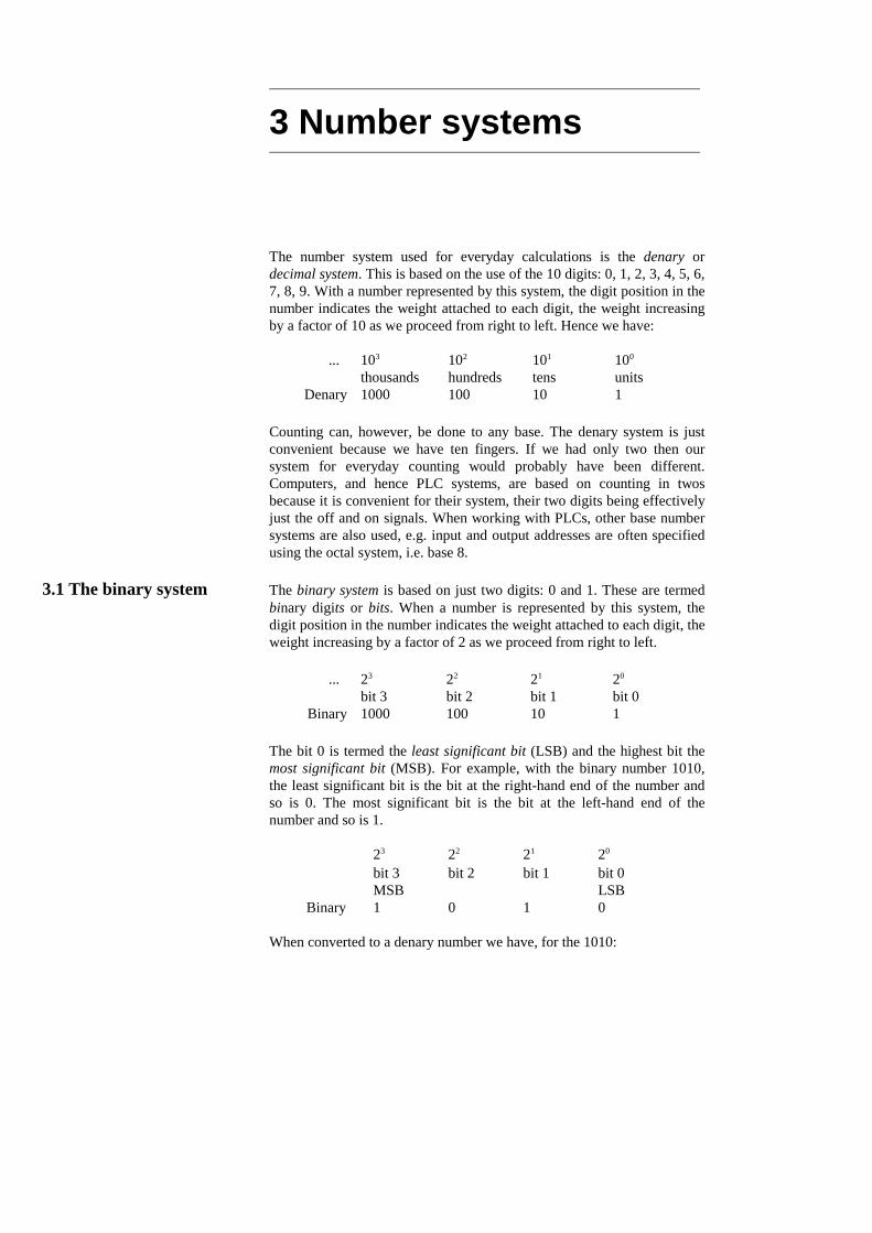
3 Number systems
The number system used for everyday calculations is the denary ordecimal system. This is based on the use of the 10 digits: 0, 1, 2, 3, 4, 5, 6,7, 8, 9. With a number represented by this system, the digit position in thenumber indicates the weight attached to each digit, the weight increasingby a factor of 10 as we proceed from right to left. Hence we have:
1101001000Denary unitstenshundredsthousands100 101 102 103 ...
Counting can, however, be done to any base. The denary system is justconvenient because we have ten fingers. If we had only two then oursystem for everyday counting would probably have been different.Computers, and hence PLC systems, are based on counting in twosbecause it is convenient for their system, their two digits being effectivelyjust the off and on signals. When working with PLCs, other base numbersystems are also used, e.g. input and output addresses are often specifiedusing the octal system, i.e. base 8.
3.1 The binary system The binary system is based on just two digits: 0 and 1. These are termedbinary digits or bits. When a number is represented by this system, thedigit position in the number indicates the weight attached to each digit, theweight increasing by a factor of 2 as we proceed from right to left.
1101001000Binary bit 0bit 1bit 2bit 320 21 22 23 ...
The bit 0 is termed the least significant bit (LSB) and the highest bit themost significant bit (MSB). For example, with the binary number 1010,the least significant bit is the bit at the right-hand end of the number andso is 0. The most significant bit is the bit at the left-hand end of thenumber and so is 1.
0 1 0 1 BinaryLSBMSBbit 0bit 1bit 2bit 320 21 22 23
When converted to a denary number we have, for the 1010:
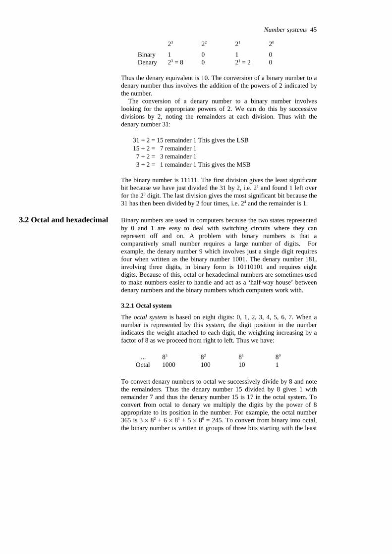
0 21 = 20 23 = 8Denary0 1 0 1 Binary20 21 22 23
Thus the denary equivalent is 10. The conversion of a binary number to adenary number thus involves the addition of the powers of 2 indicated bythe number.
The conversion of a denary number to a binary number involveslooking for the appropriate powers of 2. We can do this by successivedivisions by 2, noting the remainders at each division. Thus with thedenary number 31:
31 ÷ 2 = 15 remainder 1 This gives the LSB15 ÷ 2 = 7 remainder 1 7 ÷ 2 = 3 remainder 1 3 ÷ 2 = 1 remainder 1 This gives the MSB
The binary number is 11111. The first division gives the least significantbit because we have just divided the 31 by 2, i.e. 21 and found 1 left overfor the 20 digit. The last division gives the most significant bit because the31 has then been divided by 2 four times, i.e. 24 and the remainder is 1.
3.2 Octal and hexadecimal Binary numbers are used in computers because the two states representedby 0 and 1 are easy to deal with switching circuits where they canrepresent off and on. A problem with binary numbers is that acomparatively small number requires a large number of digits. Forexample, the denary number 9 which involves just a single digit requiresfour when written as the binary number 1001. The denary number 181,involving three digits, in binary form is 10110101 and requires eightdigits. Because of this, octal or hexadecimal numbers are sometimes usedto make numbers easier to handle and act as a ‘half-way house’ betweendenary numbers and the binary numbers which computers work with.
3.2.1 Octal system
The octal system is based on eight digits: 0, 1, 2, 3, 4, 5, 6, 7. When anumber is represented by this system, the digit position in the numberindicates the weight attached to each digit, the weighting increasing by afactor of 8 as we proceed from right to left. Thus we have:
1101001000 Octal80 81 82 83 ...
To convert denary numbers to octal we successively divide by 8 and notethe remainders. Thus the denary number 15 divided by 8 gives 1 withremainder 7 and thus the denary number 15 is 17 in the octal system. Toconvert from octal to denary we multiply the digits by the power of 8appropriate to its position in the number. For example, the octal number365 is 3 % 82 + 6 % 81 + 5 % 80 = 245. To convert from binary into octal,the binary number is written in groups of three bits starting with the least
Number systems 45
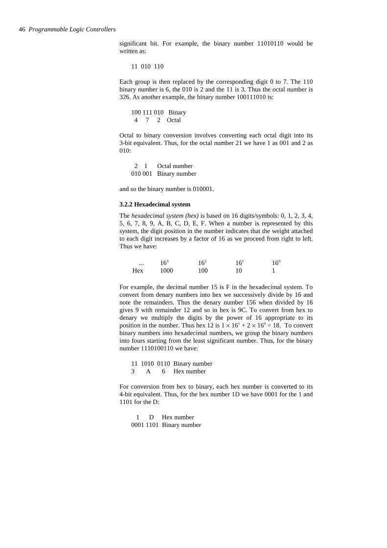
significant bit. For example, the binary number 11010110 would bewritten as:
11 010 110
Each group is then replaced by the corresponding digit 0 to 7. The 110binary number is 6, the 010 is 2 and the 11 is 3. Thus the octal number is326. As another example, the binary number 100111010 is:
100 111 010 Binary 4 7 2 Octal
Octal to binary conversion involves converting each octal digit into its3-bit equivalent. Thus, for the octal number 21 we have 1 as 001 and 2 as010:
2 1 Octal number010 001 Binary number
and so the binary number is 010001.
3.2.2 Hexadecimal system
The hexadecimal system (hex) is based on 16 digits/symbols: 0, 1, 2, 3, 4,5, 6, 7, 8, 9, A, B, C, D, E, F. When a number is represented by thissystem, the digit position in the number indicates that the weight attachedto each digit increases by a factor of 16 as we proceed from right to left.Thus we have:
1101001000 Hex160 161 162 163 ...
For example, the decimal number 15 is F in the hexadecimal system. Toconvert from denary numbers into hex we successively divide by 16 andnote the remainders. Thus the denary number 156 when divided by 16gives 9 with remainder 12 and so in hex is 9C. To convert from hex todenary we multiply the digits by the power of 16 appropriate to itsposition in the number. Thus hex 12 is 1 % 161 + 2 % 160 = 18. To convertbinary numbers into hexadecimal numbers, we group the binary numbersinto fours starting from the least significant number. Thus, for the binarynumber 1110100110 we have:
11 1010 0110 Binary number3 A 6 Hex number
For conversion from hex to binary, each hex number is converted to its4-bit equivalent. Thus, for the hex number 1D we have 0001 for the 1 and1101 for the D:
1 D Hex number0001 1101 Binary number
46 Programmable Logic Controllers

Thus the binary number is 0001 1101.Because the external world tends to deal mainly with numbers in the
denary system and computers with numbers in the binary system, there isalways the problem of conversion. There is, however, no simple linkbetween the position of digits in a denary number and the position ofdigits in a binary number. An alternative method that is often used is thebinary coded decimal system (BCD). With this system, each denary digitis coded separately in binary. For example, the denary number 15 has the5 converted into the binary number 0101 and the 1 into 0001:
1 5 Denary number0001 0101 Binary number
to give in BCD the number 0001 0101.
3.2.3 Numbers in the binary, octal, hex and BCD systems
Table 3.1 gives examples of numbers in the denary, binary, octal, hex andBCD systems.
Table 3.1 Examples of numbers in different systems
0001 0111 112110001170001 0110102010000160001 0101 F1701111150001 0100 E1601110140001 0011 D1501101130001 0010 C1401100120001 0001 B1301011110001 0000 A1201010100000 1001 91101001 90000 1000 81001000 80000 0111 7 700111 70000 0110 6 600110 60000 0101 5 500101 50000 0100 4 400100 40000 0011 3 300011 30000 0010 2 200010 20000 0001 1 100001 10000 0000 0 000000 0
BCDHexOctalBinaryDenary
3.3 Binary arithmetic Addition of binary numbers uses the following rules:
0 + 0 = 0
0 + 1 = 1 + 0 = 1
Number systems 47

1 + 1 = 10
1 + 1 + 1 = 11
Consider the addition of the binary numbers 01110 and 10011.
100001Sum 10011 01110
For bit 0 in the sum, 0 + 1 = 1. For bit 1 in the sum, 1 + 1 = 10 and so wehave 0 with 1 carried to the next column. For bit 2 in the sum, 1 + 0 + thecarried 1 = 10. For bit 3 in the sum, 1 + 0 + the carried 1 = 10. Wecontinue this through the various bits and end up with the 100001.
Subtraction of binary numbers follows the following rules:
0 − 0 = 0
1 − 0 = 1
1 − 1 = 0
When evaluating 0 − 1, a 1 is borrowed from the next column on the leftcontaining a 1. The following example illustrates this with the subtractionof 01110 from 11011:
01101Difference0111011011
For bit 0 we have 1 − 0 = 1. For bit 1 we have 1 − 1 = 0. For bit 2 we have0 − 1. We thus borrow 1 from the next column and so have 10 − 1 = 1.For bit 3 we have 0 − 1, remember we borrowed the 1. Again borrowing 1from the next column, we then have 10 − 1 = 1. For bit 4 we have 0 − 0 =0, remember we borrowed the 1.
3.3.1 Signed numbers
The binary numbers considered so far contain no indication whether theyare negative or positive and are said to be unsigned. Since there isgenerally a need to handle both positive and negative numbers there needsto be some way of distinguishing between them. This can be done byadding a sign bit. When a number is said to be signed then the mostsignificant bit is used to indicate the sign of the number, a 0 being used ifthe number is positive and a 1 if it is negative. Thus for an 8-bit numberwe have:
48 Programmable Logic Controllers
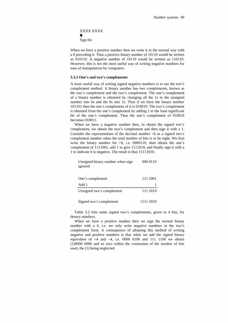
XXXX XXXX
Sign bit
When we have a positive number then we write it in the normal way witha 0 preceding it. Thus a positive binary number of 10110 would be writtenas 010110. A negative number of 10110 would be written as 110110.However, this is not the most useful way of writing negative numbers forease of manipulation by computers.
3.3.2 One’s and two’s complements
A more useful way of writing signed negative numbers is to use the two’scomplement method. A binary number has two complements, known asthe one’s complement and the two’s complement. The one’s complementof a binary number is obtained by changing all the 1s in the unsignednumber into 0s and the 0s into 1s. Thus if we have the binary number101101 then the one’s complement of it is 010010. The two’s complementis obtained from the one’s complement by adding 1 to the least significantbit of the one’s complement. Thus the one’s complement of 010010becomes 010011.
When we have a negative number then, to obtain the signed two’scomplement, we obtain the two’s complement and then sign it with a 1.Consider the representation of the decimal number −6 as a signed two’scomplement number when the total number of bits is to be eight. We firstwrite the binary number for +6, i.e. 0000110, then obtain the one’scomplement of 1111001, add 1 to give 1111010, and finally sign it with a1 to indicate it is negative. The result is thus 11111010.
1111 1010Signed two’s complement
111 1010Unsigned two’s complement 1Add 1
111 1001One’s complement
000 0110Unsigned binary number when signignored
Table 3.2 lists some signed two’s complements, given to 4 bits, fordenary numbers.
When we have a positive number then we sign the normal binarynumber with a 0, i.e. we only write negative numbers in the two’scomplement form. A consequence of adopting this method of writingnegative and positive numbers is that when we add the signed binaryequivalent of +4 and –4, i.e. 0000 0100 and 111 1100 we obtain(1)0000 0000 and so zero within the constraints of the number of bitsused, the (1) being neglected.
Number systems 49

Table 3.2 Signed two’s complements
1111−11110−21101−31100−4 1011−5
Signed 2’s complementDenary number
Subtraction of a positive number from a positive number can beconsidered to be the addition of a negative number to a positive number.Thus we obtain the signed two’s complement of the negative number andthen add it to the signed positive number. Hence, for the subtraction of thedenary number 6 from the denary number 4 we can consider the problemas being (+4) + (−6). Hence we add the signed positive number to thesigned two’s complement for the negative number.
1111 1110Sum
1111 1010(−6) as signed two’s complement
0000 0100Binary form of +4
The most significant bit, i.e. the sign, of the outcome is 1 and so the resultis negative. This is the 8-bit signed two’s complement for −2.
If we wanted to add two negative numbers then we would obtain thesigned two’s complement for each number and then add them. Whenevera number is negative we use the signed two’s complement, when positivejust the signed number.
3.3.3 Floating point numbers
Before discussing floating point numbers, consider fixed point numbers.Fixed point numbers are ones where there is a fixed location of the pointseparating integers from fractional numbers. Thus, 15.3 is an example of adenary fixed point number, 1010.1100 an example of a fixed point binarynumber and DE.2A an example of a fixed point hexadecimal number. Wehave, with the eight-bit binary number, four digits before the binary pointand four digits after it. When two such binary numbers are added by acomputing system the procedure is to recognise that the fixed point isfixed the same in both numbers so we can ignore it for the addition, carryout the addition of the numbers and then insert in the result the binarypoint in its fixed position. For example, suppose we want to add0011.1010 and 0110.1000, we drop the binary point to give:
0011 1010 + 0110 1000 = 1010 0010
Inserting the binary point then gives 1010.0010.Using fixed points does present problems. If we are concerned with
very large or very small numbers we could end up with a large number ofzeros between the integers and the point, e.g. 0.000 000 000 000 023. For
50 Programmable Logic Controllers
this reason scientific notation is used for such numbers. Thus, the abovenumber might be written as 0.23 % 10–13 or 2.3 % 10–14 or 23 % 10–15.Likewise, the binary number 0.0000 0111 0010 might be represented as110010 % 2–12 (the 12 would also be in binary format) or 11001.0 % 2–11
(the 11 being in binary format). Such notation has a floating point. A floating point number is in the form a % re, where a is termed the
mantissa, r the radix or base and e the exponent or power. With binarynumbers the base is understood to be 2, i.e. we have a % 2e, and when weknow we are dealing with binary numbers we need not store the base withthe number. Thus a computing system needs, in addition to storing thesign, i.e. whether positive or negative, to store the mantissa and theexponent.
Because with floating point numbers it is possible to store a number inseveral different ways, e.g. 0.1 % 102 and 0.01 % 103, with computingsystems such numbers are normalised. This means that they are all put inthe form 0.1 % re. Thus, with binary numbers we have 0.1 % 2e, e.g. if wehad 0.00001001 it would become 0.1001 % 2–4. In order to take account ofthe sign of a binary number we then add a sign bit of 0 for a positivenumber and 1 for a negative number. Thus the number 0.1001 % 2–4
becomes 1.1001 % 2–4 if negative and 0.1001 % 2–4 if positive.Unlike fixed point numbers, floating point numbers cannot be directly
added unless the exponents are the same. Thus to carry out addition weneed to make the exponents the same.
3.4 PLC data Most PLCs operate with a 16-bit word, the term word being used for thegroup of bits constituting some information. This allows a positivenumber in the range 0 to +65 535, i.e. 1111 1111 1111 1111, to berepresented or a signed number in the range –32 768 to +32 767 in two’scomplement, the most significant bit then representing the sign. Suchsigned numbers are referred to as integers with the symbol INT beingused with inputs and outputs in programs of such 16-bit words. The termSINT is used for short integer numbers where only 8-bits are used, suchnumbers giving the range –128 to +127. The term DINT is used fordouble integer numbers where 32 bits are used, such numbers giving therange –231 to +231 – 1. LINT is used for long integer numbers where 64bits are used, such numbers giving the range –263 to +263 – 1. Wherenumbers are not signed the symbols UINT, USINT, UDINT and ULINTare used with integers, short integers, double integers and long integers.
Decimal fractions are referred to as real or floating point numbers,being represented by the symbol REAL for inputs and outputs inprograms. These consist of two 16-bit words and so we might have1.234567E+03 for the number 1.234 567 × 10+3, the E indicating that thenumber that follows is the exponent. The term LREAL is used for longreal numbers where 64 bits are used.
The term BOOL is used for Boolean type data, such data being on/offvalues, i.e. 0 or 1, and thus represented by single bits.
Time duration, e.g. for the duration of a process, is represented by theIEC (International Electrotechnical Commission) standard using thesymbols d for days, h for hours, m for minutes, s for seconds and ms formilliseconds as, for example, T#12d2h5s3ms or TIME#12d2h5s for 12
Number systems 51
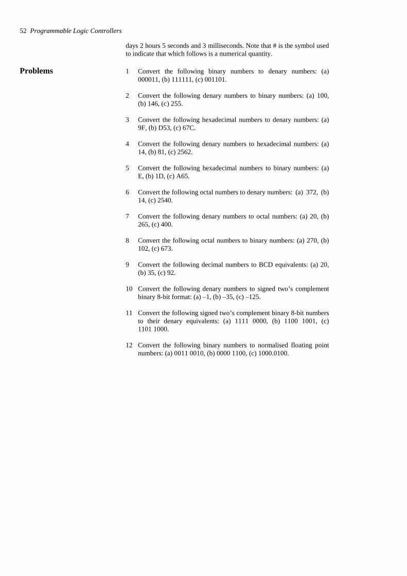
days 2 hours 5 seconds and 3 milliseconds. Note that # is the symbol usedto indicate that which follows is a numerical quantity.
Problems 1 Convert the following binary numbers to denary numbers: (a)000011, (b) 111111, (c) 001101.
2 Convert the following denary numbers to binary numbers: (a) 100,(b) 146, (c) 255.
3 Convert the following hexadecimal numbers to denary numbers: (a)9F, (b) D53, (c) 67C.
4 Convert the following denary numbers to hexadecimal numbers: (a)14, (b) 81, (c) 2562.
5 Convert the following hexadecimal numbers to binary numbers: (a)E, (b) 1D, (c) A65.
6 Convert the following octal numbers to denary numbers: (a) 372, (b)14, (c) 2540.
7 Convert the following denary numbers to octal numbers: (a) 20, (b)265, (c) 400.
8 Convert the following octal numbers to binary numbers: (a) 270, (b)102, (c) 673.
9 Convert the following decimal numbers to BCD equivalents: (a) 20,(b) 35, (c) 92.
10 Convert the following denary numbers to signed two’s complementbinary 8-bit format: (a) –1, (b) –35, (c) –125.
11 Convert the following signed two’s complement binary 8-bit numbersto their denary equivalents: (a) 1111 0000, (b) 1100 1001, (c)1101 1000.
12 Convert the following binary numbers to normalised floating pointnumbers: (a) 0011 0010, (b) 0000 1100, (c) 1000.0100.
52 Programmable Logic Controllers

4 I/O processing
This chapter continues the discussion of inputs and outputs from Chapter2 and is a brief consideration of the processing of the signals from inputand output devices. The input/output (I/O) unit provides the interfacebetween the PLC controller and the outside world and must thereforeprovide the necessary signal conditioning to get the signal to the requiredlevel and also to isolate it from possible electrical hazards such as highvoltages. This chapter includes the forms of typical input/output modulesand, in an installation where sensors are some distance from the PLCprocessing, their communication links to the PLC.
4.1 Input/output units Input signals from sensors and the outputs required for actuating devicescan be:
1 Analogue, i.e. a signal whose size is related to the size of the quantitybeing sensed.
2 Discrete, i.e. essentially just an on−off signal.3 Digital, i.e. a sequence of pulses.
The CPU, however, must have an input of digital signals of a particularsize, normally 0 to 5 V. The output from the CPU is digital, normally 0 to5 V. Thus there is generally a need to manipulate input and output signalsso that they are in the required form.
The input/output (I/O) units of PLCs are designed so that a range ofinput signals can be changed into 5 V digital signals and so that a range ofoutputs are available to drive external devices. It is this in-built facility toenable a range of inputs and outputs to be handled which makes PLCs soeasy to use. The following is a brief indication of the basic circuits usedfor input and output units. In the case of rack instruments they aremounted on cards which can be plugged into the racks and so theinput/output characteristics of the PLC can thus be changed by changingthe cards. A single box form of PLC has input/output units incorporatedby the manufacturer.
4.1.1 Input units
The terms sourcing and sinking refer to the manner in which d.c. devicesare interfaced with the PLC (see Section 1.3.5). For a PLC input unit, withsourcing it is the source of the current supply for the input deviceconnected to it (Figure 4.1(a)). With sinking, the input device provides thecurrent to the input unit (Figure 4.1(b)).
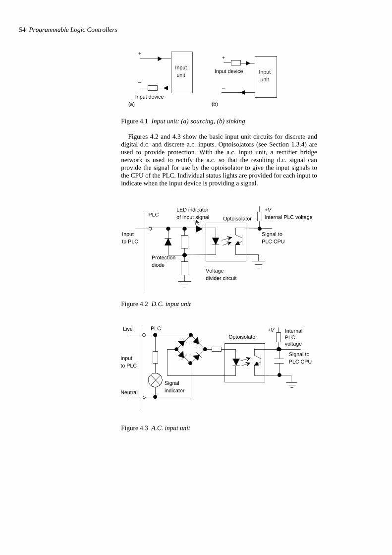
+
–
Inputunit
Input device(a)
+
–
Inputunit
Input device
(b)
Figure 4.1 Input unit: (a) sourcing, (b) sinking
Figures 4.2 and 4.3 show the basic input unit circuits for discrete anddigital d.c. and discrete a.c. inputs. Optoisolators (see Section 1.3.4) areused to provide protection. With the a.c. input unit, a rectifier bridgenetwork is used to rectify the a.c. so that the resulting d.c. signal canprovide the signal for use by the optoisolator to give the input signals tothe CPU of the PLC. Individual status lights are provided for each input toindicate when the input device is providing a signal.
Optoisolator
Signal toPLC CPU
PLC
Protectiondiode
Voltagedivider circuit
Inputto PLC
LED indicatorof input signal
+VInternal PLC voltage
Figure 4.2 D.C. input unit
Optoisolator
Signal toPLC CPU
PLC
Inputto PLC
+V InternalLive
Neutral
Signalindicator
voltagePLC
Figure 4.3 A.C. input unit
54 Programmable Logic Controllers
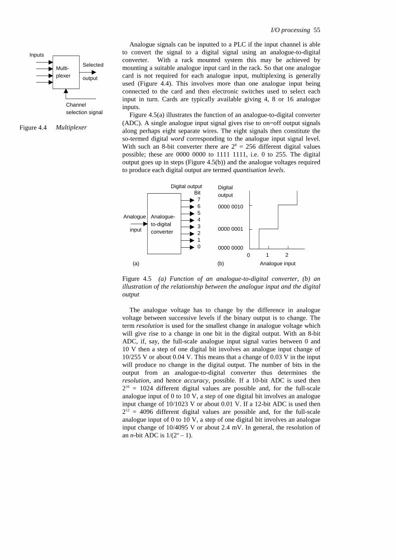
Analogue signals can be inputted to a PLC if the input channel is ableto convert the signal to a digital signal using an analogue-to-digitalconverter. With a rack mounted system this may be achieved bymounting a suitable analogue input card in the rack. So that one analoguecard is not required for each analogue input, multiplexing is generallyused (Figure 4.4). This involves more than one analogue input beingconnected to the card and then electronic switches used to select eachinput in turn. Cards are typically available giving 4, 8 or 16 analogueinputs.
Figure 4.5(a) illustrates the function of an analogue-to-digital converter(ADC). A single analogue input signal gives rise to on−off output signalsalong perhaps eight separate wires. The eight signals then constitute theso-termed digital word corresponding to the analogue input signal level.With such an 8-bit converter there are 28 = 256 different digital valuespossible; these are 0000 0000 to 1111 1111, i.e. 0 to 255. The digitaloutput goes up in steps (Figure 4.5(b)) and the analogue voltages requiredto produce each digital output are termed quantisation levels.
Analogue-to-digitalconverter
Analogue
input
Digital outputBit
76543210
(a)
0000 0000
0000 0001
0000 0010
Digitaloutput
0 1 2Analogue input(b)
Figure 4.5 (a) Function of an analogue-to-digital converter, (b) anillustration of the relationship between the analogue input and the digitaloutput
The analogue voltage has to change by the difference in analoguevoltage between successive levels if the binary output is to change. Theterm resolution is used for the smallest change in analogue voltage whichwill give rise to a change in one bit in the digital output. With an 8-bitADC, if, say, the full-scale analogue input signal varies between 0 and10 V then a step of one digital bit involves an analogue input change of10/255 V or about 0.04 V. This means that a change of 0.03 V in the inputwill produce no change in the digital output. The number of bits in theoutput from an analogue-to-digital converter thus determines theresolution, and hence accuracy, possible. If a 10-bit ADC is used then210 = 1024 different digital values are possible and, for the full-scaleanalogue input of 0 to 10 V, a step of one digital bit involves an analogueinput change of 10/1023 V or about 0.01 V. If a 12-bit ADC is used then212 = 4096 different digital values are possible and, for the full-scaleanalogue input of 0 to 10 V, a step of one digital bit involves an analogueinput change of 10/4095 V or about 2.4 mV. In general, the resolution ofan n-bit ADC is 1/(2n – 1).
I/O processing 55
Inputs
Multi-plexer
Selected
output
Channelselection signal
Figure 4.4 Multiplexer

The following illustrates the analogue-to-digital conversion for an 8-bitconverter when the analogue input is in the range 0 to 10 V:
etc. 0000 1000 0.32 0000 0111 0.28 0000 0110 0.24 0000 0101 0.20 0000 0100 0.16 0000 0011 0.12 0000 0010 0.08 0000 0001 0.04 0000 0000 0.00
Digital output (V)Analogue input (V)
To illustrate the above, consider a thermocouple used as a sensor with aPLC and giving an output of 0.5 mV per oC. What will be the accuracywith which the PLC will activate the output device if the thermocouple isconnected to an analogue input with a range of 0 to 10 V d.c and using a10-bit analogue-to-digital converter? With a 10-bit converter there is210 = 1024 bits covering the 0 to 10 V range. Thus a change of 1 bitcorresponds to 10/1023 V or about 0.01 V, i.e. 10 mV. Hence theaccuracy with which the PLC recognises the input from the thermocoupleis ±5 mV or ±10oC.
4.1.2 Output units
With a PLC output unit, when it provides the current for the output device(Figure 4.6(a)) it is said to be sourcing and when the output deviceprovides the current to the output unit it is said to be sinking (Figure4.6(b)). Quite often, sinking input units are used for interfacing withelectronic equipment and sourcing output units for interfacing withsolenoids.
Outputunit
OutputunitLoad Load
– +
(a) (b)
Figure 4.6 Output unit: (a) sourcing, (b) sinking
Output units can be relay, transistor or triac. Figure 4.7 shows the basicform of a relay output unit, Figure 4.8 that of a transistor output unit andFigure 4.9 that of a triac output unit.
56 Programmable Logic Controllers
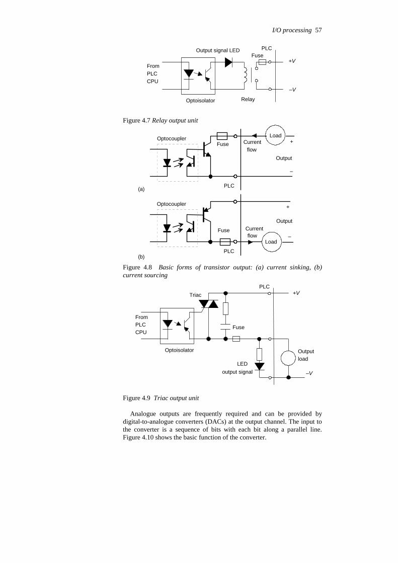
Optoisolator
FromPLCCPU
Relay
PLCOutput signal LEDFuse
+V
–V
Figure 4.7 Relay output unit
FuseOptocoupler
Output
PLC
Fuse
Optocoupler
Output
PLC
(a)
(b)
–
+
Load
Load
+Currentflow
Currentflow –
Figure 4.8 Basic forms of transistor output: (a) current sinking, (b)current sourcing
Optoisolator
FromPLCCPU
PLC
LEDoutput signal
Outputload
+V
–V
Triac
Fuse
Figure 4.9 Triac output unit
Analogue outputs are frequently required and can be provided bydigital-to-analogue converters (DACs) at the output channel. The input tothe converter is a sequence of bits with each bit along a parallel line.Figure 4.10 shows the basic function of the converter.
I/O processing 57
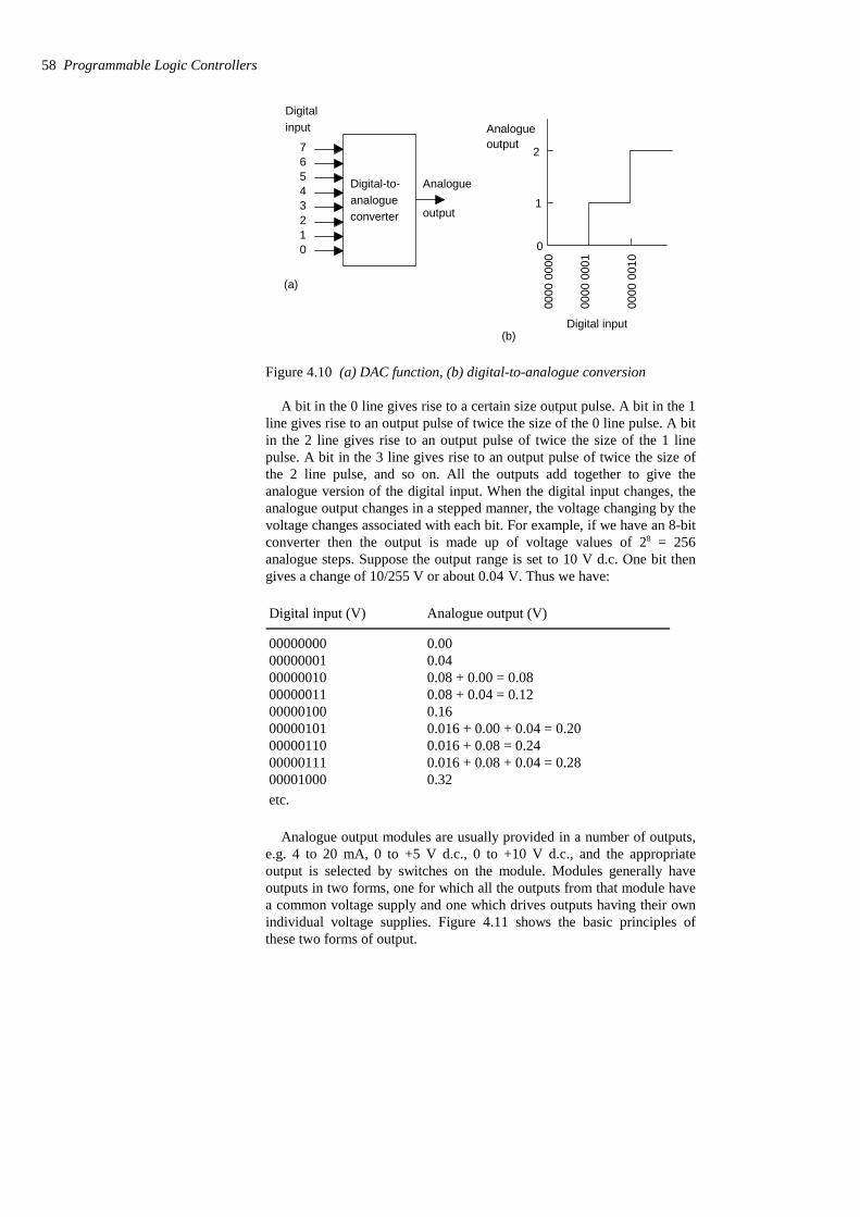
Digital-to-analogueconverter
76543210
Digitalinput
Analogue
output
0000
000
0
0000
000
1
0000
001
0
Digital input
0
Analogue
(b)
(a)
output
1
2
Figure 4.10 (a) DAC function, (b) digital-to-analogue conversion
A bit in the 0 line gives rise to a certain size output pulse. A bit in the 1line gives rise to an output pulse of twice the size of the 0 line pulse. A bitin the 2 line gives rise to an output pulse of twice the size of the 1 linepulse. A bit in the 3 line gives rise to an output pulse of twice the size ofthe 2 line pulse, and so on. All the outputs add together to give theanalogue version of the digital input. When the digital input changes, theanalogue output changes in a stepped manner, the voltage changing by thevoltage changes associated with each bit. For example, if we have an 8-bitconverter then the output is made up of voltage values of 28 = 256analogue steps. Suppose the output range is set to 10 V d.c. One bit thengives a change of 10/255 V or about 0.04 V. Thus we have:
etc. 0.32 00001000 0.016 + 0.08 + 0.04 = 0.28 00000111 0.016 + 0.08 = 0.24 00000110 0.016 + 0.00 + 0.04 = 0.20 00000101 0.16 00000100 0.08 + 0.04 = 0.12 00000011 0.08 + 0.00 = 0.08 00000010 0.04 00000001 0.00 00000000
Analogue output (V)Digital input (V)
Analogue output modules are usually provided in a number of outputs,e.g. 4 to 20 mA, 0 to +5 V d.c., 0 to +10 V d.c., and the appropriateoutput is selected by switches on the module. Modules generally haveoutputs in two forms, one for which all the outputs from that module havea common voltage supply and one which drives outputs having their ownindividual voltage supplies. Figure 4.11 shows the basic principles ofthese two forms of output.
58 Programmable Logic Controllers

Commonlive
Outputloads
1
2
3
4
5
6
7
PLC
Fuses
(a)
1
2
3
4
L1
N1
L2
N2
L3
N3
L4
N4
Outputs
PLC
Fuses
Individualsupplies
(b)
Figure 4.11 Forms of output: (a) common supply, (b) individual supplies
4.2 Signal conditioning When connecting sensors which generate digital or discrete signals to aninput unit, care has to be taken to ensure that voltage levels match.However, many sensors generate analogue signals. In order to avoidhaving a multiplicity of analogue input channels to cope with the widediversity of analogue signals that can be generated by sensors, externalsignal conditioning is often used to bring analogue signals to a commonrange and so allow a standard form of analogue input channel to be used.
A common standard that is used (Figure 4.12) is to convert analoguesignals to a current in the range 4 to 20 mA and thus to a voltage bypassing it through a 250 resistance to give a 1 to 5 V input signal. Thus,for example, a sensor used to monitor liquid level in the height range 0 to1 m would have the 0 level represented by 4 mA and the 1 m representedby 20 mA. The use of 4 mA to represent the low end of the analoguerange serves the purpose of distinguishing between when the sensor isindicating zero and when the sensor is not working and giving zeroresponse for that reason. When this happens the current would be 0 mA.The 4 mA also is often a suitable current to operate a sensor and soeliminate the need for a separate power supply.
1 to 5 V
4 to 20 mA
250
Figure 4.12 Standard analogue signal
I/O processing 59
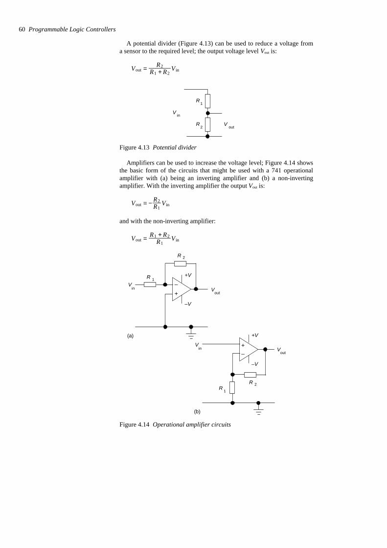
A potential divider (Figure 4.13) can be used to reduce a voltage froma sensor to the required level; the output voltage level Vout is:
Vout = R2R1 + R2
V in
R
R
V
V
in
out
1
2
Figure 4.13 Potential divider
Amplifiers can be used to increase the voltage level; Figure 4.14 showsthe basic form of the circuits that might be used with a 741 operationalamplifier with (a) being an inverting amplifier and (b) a non-invertingamplifier. With the inverting amplifier the output Vout is:
Vout = − R2R1
Vin
and with the non-inverting amplifier:
Vout = R1 + R2R1
V in
+V
–V
R
R
1
2
outin
VV
(a)
–+
+V
–V
RR 1
2
outin
VV
(b)
–+
Figure 4.14 Operational amplifier circuits
60 Programmable Logic Controllers

Often a differential amplifier is needed to amplify the differencebetween two input voltages. Such is the case when a sensor, e.g. a straingauge, is connected in a Wheatstone bridge and the output is thedifference between two voltages or a thermocouple where the voltagedifference between the hot and cold junctions is required. Figure 4.14shows the basic form of an operational amplifier circuit for this purpose.The output voltage Vout is:
Vout = R2R1
(V2 − V1)
VV
V
R
R
R
R
1
2
1
1
2
2
out
Figure 4.15 Differential amplifier
As an illustration of the use of signal conditioning, Figure 4.16 showsthe arrangement that might be used for a strain gauge sensor. The sensor isconnected in a Wheatstone bridge and the out-of-balance potentialdifference amplified by a differential amplifier before being fed via ananalogue-to-digital converter unit which is part of the analogue input portof the PLC.
R
R
R
R
1
1
2
2
+V
Straingauge
ADC PLC
Differential amplifier
Wheatstone bridge
Figure 4.16 Signal conditioning with a strain gauge sensor
I/O processing 61

4.3 Remote connections When there are many inputs or outputs located considerable distancesaway from the PLC, while it would be possible to run cables from eachsuch device to the PLC a more economic solution is to use input/outputmodules in the vicinity of the inputs and outputs and use just a single corecable to connect each, over the long distances, to the PLC instead of themulticore cable that would be needed without such distant I/O modules(Figure 4.17).
Twisted-pair, or screened cable, or
Input/output module
Power
PLC
fibre optic cable, communicationlink
Remote input/output module
Input andoutputconnections
Figure 4.17 Use of remote input/output module
In some situations a number of PLCs may be linked together with amaster PLC unit sending and receiving input/output data from the otherunits (Figure 4.18). The distant PLCs do not contain the control programsince all the control processing is carried out by the master PLC.
Communicationmodule
Communicationport
Units located some distance from the PLC
Other input/outputmodules
PLC
PLC
MasterPLC
Figure 4.18 Use of remote input/output PLC systems
The cables used for communicating data between remote input/outputmodules and a central PLC, remote PLCs and the master PLC are
62 Programmable Logic Controllers

typically twisted-pair cabling, often routed through grounded steelconduit in order to reduce electrical ‘noise’. Coaxial cable enables higherdata rates to be transmitted and does not require the shielding of steelconduit. Fibre-optic cabling has the advantage of resistance to noise,small size and flexibility and is now becoming more widely used.
4.3.1 Serial and parallel communications
Serial communication is when data is transmitted one bit at a time (Figure4.19(a)). Thus if an 8-bit word is to be transmitted, the eight bits aretransmitted one at a time in sequence along a cable. This means that a dataword has to be separated into its constituent bits for transmission and thenreassembled into the word when received. Parallel communication iswhen all the constituent bits of a word are simultaneously transmittedalong parallel cables (Figure 4.19(b)). This allows data to be transmittedover short distances at high speeds.
7 6 5 4 3 2 1 0Bits
Bits76543210
(a)
(b)
Figure 4.19 (a) Serial communication, (b) parallel communication
Serial communication is used for transmitting data over long distances.It is much cheaper to run, for serial communication, a single core cableover a long distance than the multicore cables that would be needed forparallel communication. With a PLC system, serial communication mightbe used for the connection between a computer, when used as aprogramming terminal, and a PLC. Parallel communication might be usedwhen connecting laboratory instruments to the system. However,internally, PLCs work, for speed, with parallel communications. Thus,circuits called UARTS (universal asynchronous receivers–transmitters)have to be used at input/output ports to converts serial communicationssignals to parallel.
4.3.2 Serial standards
For successful serial communications to occur, it is necessary to specify:
1 The voltage levels to be used for signals, i.e. what signal represents a0 and what represents a 1.
2 What the bit patterns being transmitted mean and how the message isbuilt up. Bear in mind that a sequence of words are being sent alongthe same cable and it is necessary to be able to be able to determinewhen one word starts and finishes and the next word starts.
3 The speed at which the bit pattern is to be sent, i.e. the number of bitsper second.
I/O processing 63
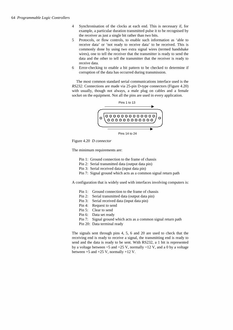
4 Synchronisation of the clocks at each end. This is necessary if, forexample, a particular duration transmitted pulse it to be recognised bythe receiver as just a single bit rather than two bits.
5 Protocols, or flow controls, to enable such information as ‘able toreceive data’ or ‘not ready to receive data’ to be received. This iscommonly done by using two extra signal wires (termed handshakewires), one to tell the receiver that the transmitter is ready to send thedata and the other to tell the transmitter that the receiver is ready toreceive data.
6 Error-checking to enable a bit pattern to be checked to determine ifcorruption of the data has occurred during transmission.
The most common standard serial communications interface used is theRS232. Connections are made via 25-pin D-type connectors (Figure 4.20)with usually, though not always, a male plug on cables and a femalesocket on the equipment. Not all the pins are used in every application.
Pins 1 to 13
Pins 14 to 24
Figure 4.20 D connector
The minimum requirements are:
Pin 1: Ground connection to the frame of chassisPin 2: Serial transmitted data (output data pin)Pin 3: Serial received data (input data pin)Pin 7: Signal ground which acts as a common signal return path
A configuration that is widely used with interfaces involving computers is:
Pin 1: Ground connection to the frame of chassisPin 2: Serial transmitted data (output data pin)Pin 3: Serial received data (input data pin)Pin 4: Request to sendPin 5: Clear to sendPin 6: Data set readyPin 7: Signal ground which acts as a common signal return pathPin 20: Data terminal ready
The signals sent through pins 4, 5, 6 and 20 are used to check that thereceiving end is ready to receive a signal, the transmitting end is ready tosend and the data is ready to be sent. With RS232, a 1 bit is representedby a voltage between −5 and −25 V, normally −12 V, and a 0 by a voltagebetween +5 and +25 V, normally +12 V.
64 Programmable Logic Controllers
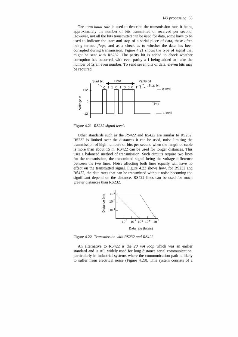
The term baud rate is used to describe the transmission rate, it beingapproximately the number of bits transmitted or received per second.However, not all the bits transmitted can be used for data, some have to beused to indicate the start and stop of a serial piece of data, these oftenbeing termed flags, and as a check as to whether the data has beencorrupted during transmission. Figure 4.21 shows the type of signal thatmight be sent with RS232. The parity bit is added to check whethercorruption has occurred, with even parity a 1 being added to make thenumber of 1s an even number. To send seven bits of data, eleven bits maybe required.
Start bit Data
1 1 0 1 0 0 00 1
Parity bit
Time
0 level
1 level
Vol
tage
V
1 Stop bit+12
0
–12
Figure 4.21 RS232 signal levels
Other standards such as the RS422 and RS423 are similar to RS232.RS232 is limited over the distances it can be used, noise limiting thetransmission of high numbers of bits per second when the length of cableis more than about 15 m. RS422 can be used for longer distances. Thisuses a balanced method of transmission. Such circuits require two linesfor the transmission, the transmitted signal being the voltage differencebetween the two lines. Noise affecting both lines equally will have noeffect on the transmitted signal. Figure 4.22 shows how, for RS232 andRS422, the data rates that can be transmitted without noise becoming toosignificant depend on the distance. RS422 lines can be used for muchgreater distances than RS232.
Dis
tanc
e (m
)
Data rate (bits/s)
10
10
10
10 10 10 10 10
3
1
2
3 4 5 6 7
Figure 4.22 Transmission with RS232 and RS422
An alternative to RS422 is the 20 mA loop which was an earlierstandard and is still widely used for long distance serial communication,particularly in industrial systems where the communication path is likelyto suffer from electrical noise (Figure 4.23). This system consists of a
I/O processing 65
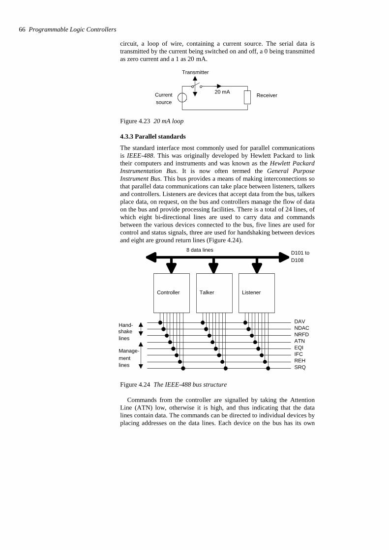
circuit, a loop of wire, containing a current source. The serial data istransmitted by the current being switched on and off, a 0 being transmittedas zero current and a 1 as 20 mA.
Currentsource
Transmitter
Receiver20 mA
Figure 4.23 20 mA loop
4.3.3 Parallel standards
The standard interface most commonly used for parallel communicationsis IEEE-488. This was originally developed by Hewlett Packard to linktheir computers and instruments and was known as the Hewlett PackardInstrumentation Bus. It is now often termed the General PurposeInstrument Bus. This bus provides a means of making interconnections sothat parallel data communications can take place between listeners, talkersand controllers. Listeners are devices that accept data from the bus, talkersplace data, on request, on the bus and controllers manage the flow of dataon the bus and provide processing facilities. There is a total of 24 lines, ofwhich eight bi-directional lines are used to carry data and commandsbetween the various devices connected to the bus, five lines are used forcontrol and status signals, three are used for handshaking between devicesand eight are ground return lines (Figure 4.24).
8 data lines
Controller Talker Listener
Hand-
lines
Manage-ment
D101 toD108
DAVNDACNRFDATNEQIIFCREHSRQ
shake
lines
Figure 4.24 The IEEE-488 bus structure
Commands from the controller are signalled by taking the AttentionLine (ATN) low, otherwise it is high, and thus indicating that the datalines contain data. The commands can be directed to individual devices byplacing addresses on the data lines. Each device on the bus has its own
66 Programmable Logic Controllers
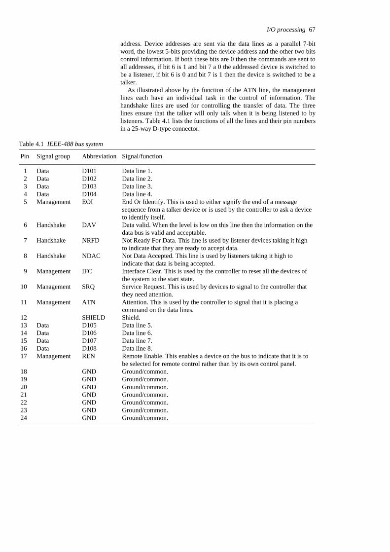
address. Device addresses are sent via the data lines as a parallel 7-bitword, the lowest 5-bits providing the device address and the other two bitscontrol information. If both these bits are 0 then the commands are sent toall addresses, if bit 6 is 1 and bit 7 a 0 the addressed device is switched tobe a listener, if bit 6 is 0 and bit 7 is 1 then the device is switched to be atalker.
As illustrated above by the function of the ATN line, the managementlines each have an individual task in the control of information. Thehandshake lines are used for controlling the transfer of data. The threelines ensure that the talker will only talk when it is being listened to bylisteners. Table 4.1 lists the functions of all the lines and their pin numbersin a 25-way D-type connector.
Table 4.1 IEEE-488 bus system
Ground/common.GND24 Ground/common.GND23 Ground/common.GND22 Ground/common.GND21 Ground/common.GND20 Ground/common.GND19 Ground/common.GND18
Remote Enable. This enables a device on the bus to indicate that it is tobe selected for remote control rather than by its own control panel.
RENManagement17 Data line 8.D108Data16 Data line 7.D107Data15 Data line 6.D106Data14 Data line 5.D105Data13 Shield.SHIELD12
Attention. This is used by the controller to signal that it is placing acommand on the data lines.
ATNManagement11
Service Request. This is used by devices to signal to the controller thatthey need attention.
SRQ Management10
Interface Clear. This is used by the controller to reset all the devices ofthe system to the start state.
IFCManagement 9
Not Data Accepted. This line is used by listeners taking it high toindicate that data is being accepted.
NDACHandshake 8
Not Ready For Data. This line is used by listener devices taking it highto indicate that they are ready to accept data.
NRFDHandshake 7
Data valid. When the level is low on this line then the information on thedata bus is valid and acceptable.
DAVHandshake 6
End Or Identify. This is used to either signify the end of a messagesequence from a talker device or is used by the controller to ask a deviceto identify itself.
EOIManagement 5 Data line 4.D104Data 4 Data line 3.D103Data 3 Data line 2.D102Data 2 Data line 1.D101Data 1
Signal/functionAbbreviationSignal groupPin
I/O processing 67
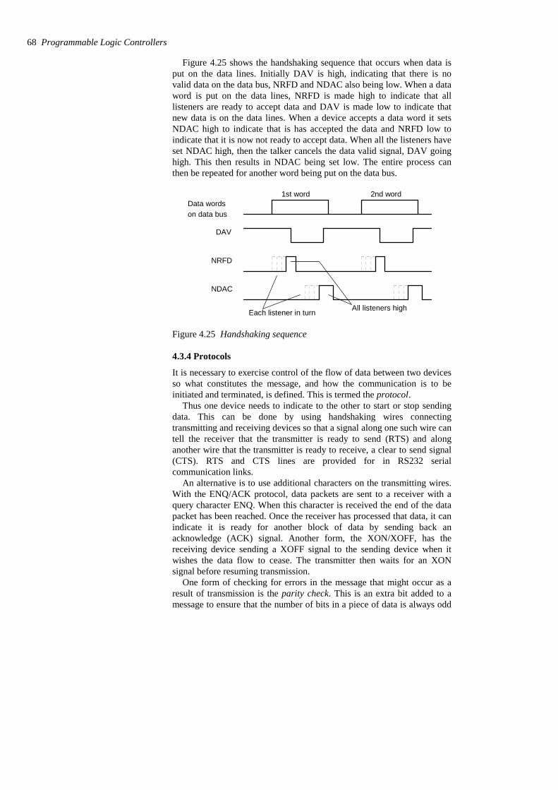
Figure 4.25 shows the handshaking sequence that occurs when data isput on the data lines. Initially DAV is high, indicating that there is novalid data on the data bus, NRFD and NDAC also being low. When a dataword is put on the data lines, NRFD is made high to indicate that alllisteners are ready to accept data and DAV is made low to indicate thatnew data is on the data lines. When a device accepts a data word it setsNDAC high to indicate that is has accepted the data and NRFD low toindicate that it is now not ready to accept data. When all the listeners haveset NDAC high, then the talker cancels the data valid signal, DAV goinghigh. This then results in NDAC being set low. The entire process canthen be repeated for another word being put on the data bus.
Data words1st word 2nd word
DAV
NRFD
NDAC
Each listener in turn All listeners high
on data bus
Figure 4.25 Handshaking sequence
4.3.4 Protocols
It is necessary to exercise control of the flow of data between two devicesso what constitutes the message, and how the communication is to beinitiated and terminated, is defined. This is termed the protocol.
Thus one device needs to indicate to the other to start or stop sendingdata. This can be done by using handshaking wires connectingtransmitting and receiving devices so that a signal along one such wire cantell the receiver that the transmitter is ready to send (RTS) and alonganother wire that the transmitter is ready to receive, a clear to send signal(CTS). RTS and CTS lines are provided for in RS232 serialcommunication links.
An alternative is to use additional characters on the transmitting wires.With the ENQ/ACK protocol, data packets are sent to a receiver with aquery character ENQ. When this character is received the end of the datapacket has been reached. Once the receiver has processed that data, it canindicate it is ready for another block of data by sending back anacknowledge (ACK) signal. Another form, the XON/XOFF, has thereceiving device sending a XOFF signal to the sending device when itwishes the data flow to cease. The transmitter then waits for an XONsignal before resuming transmission.
One form of checking for errors in the message that might occur as aresult of transmission is the parity check. This is an extra bit added to amessage to ensure that the number of bits in a piece of data is always odd
68 Programmable Logic Controllers
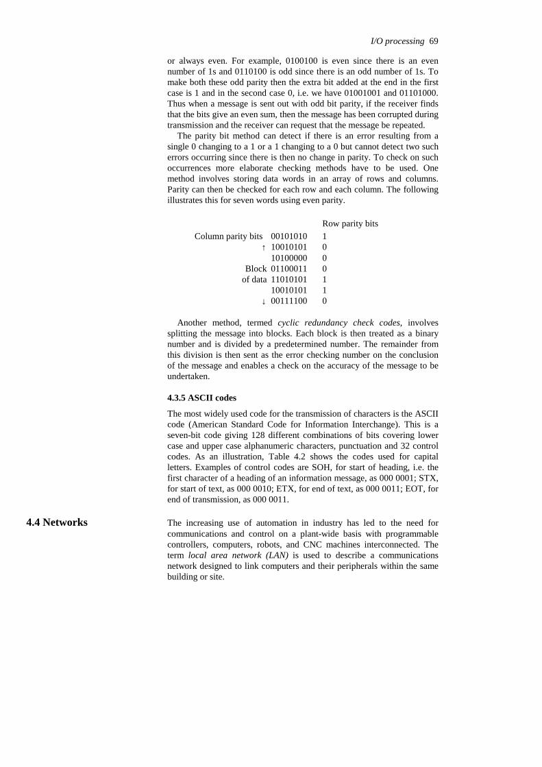
or always even. For example, 0100100 is even since there is an evennumber of 1s and 0110100 is odd since there is an odd number of 1s. Tomake both these odd parity then the extra bit added at the end in the firstcase is 1 and in the second case 0, i.e. we have 01001001 and 01101000.Thus when a message is sent out with odd bit parity, if the receiver findsthat the bits give an even sum, then the message has been corrupted duringtransmission and the receiver can request that the message be repeated.
The parity bit method can detect if there is an error resulting from asingle 0 changing to a 1 or a 1 changing to a 0 but cannot detect two sucherrors occurring since there is then no change in parity. To check on suchoccurrences more elaborate checking methods have to be used. Onemethod involves storing data words in an array of rows and columns.Parity can then be checked for each row and each column. The followingillustrates this for seven words using even parity.
0 00111100 ↓1 10010101 1 11010101 of data0 01100011 Block0 10100000 0 10010101 ↑100101010 Column parity bits Row parity bits
Another method, termed cyclic redundancy check codes, involvessplitting the message into blocks. Each block is then treated as a binarynumber and is divided by a predetermined number. The remainder fromthis division is then sent as the error checking number on the conclusionof the message and enables a check on the accuracy of the message to beundertaken.
4.3.5 ASCII codes
The most widely used code for the transmission of characters is the ASCIIcode (American Standard Code for Information Interchange). This is aseven-bit code giving 128 different combinations of bits covering lowercase and upper case alphanumeric characters, punctuation and 32 controlcodes. As an illustration, Table 4.2 shows the codes used for capitalletters. Examples of control codes are SOH, for start of heading, i.e. thefirst character of a heading of an information message, as 000 0001; STX,for start of text, as 000 0010; ETX, for end of text, as 000 0011; EOT, forend of transmission, as 000 0011.
4.4 Networks The increasing use of automation in industry has led to the need forcommunications and control on a plant-wide basis with programmablecontrollers, computers, robots, and CNC machines interconnected. Theterm local area network (LAN) is used to describe a communicationsnetwork designed to link computers and their peripherals within the samebuilding or site.
I/O processing 69

Table 4.2 Examples of ASCII codes
101 1010Z100 1101M101 1001Y100 1100L101 1000X100 1011K
011 10019101 0111W100 1010J011 10008101 0110V100 1001I011 01117101 0101U100 1000H011 01106101 0100T100 0111G011 01015101 0011S100 0110F011 01004101 0010R100 0101E011 00113101 0001Q100 0100D011 00102101 0000P100 0011C011 00011100 1111O100 0010B011 00000100 1110N100 0001A
ASCIIASCIIASCII
Networks can take three basic forms. With the star form (Figure4.26(a)) the terminals are each directly linked to a central computer,termed the host, or master with the terminals being termed slaves. Thehost contains the memory, processing and switching equipment to enablethe terminals to communicate. Access to the terminals is by the hostasking each terminal in turn whether it wants to talk or listen. With the busor single highway type of network (Figure 4.26(b)), each of the terminalsis linked into a single cable and so each transmitter/receiver has a directpath to each other transmitter/receiver in the network. Methods, i.e.protocols, have to be adopted to ensure that no more than one terminaltalks at once, otherwise confusion can occur. A terminal has to be able todetect whether another terminal is talking before it starts to talk. With thering network (Figure 4.26(c)), a continuous cable, in the form of a ring,links all the terminals. Again methods have to be employed to enablecommunications from different terminals without messages becomingmixed up. The single highway and the ring methods are often termed peerto peer in that each terminal has equal status. Such a system allows manystations to use the same network.
Host
Terminals(a)
Bus/single highway
Terminals
(b)
(c)
Terminals
Figure 4.26 Networks: (a) star, (b) bus/single highway, (c) ring
70 Programmable Logic Controllers
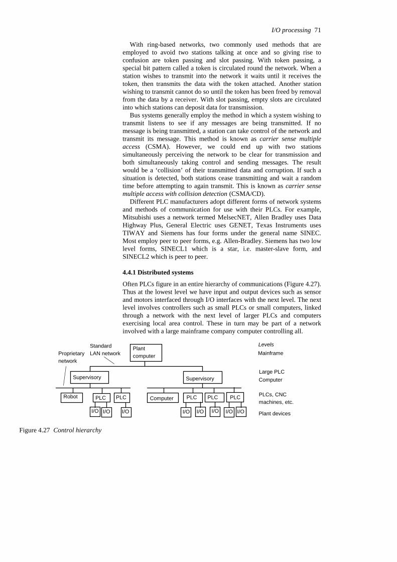
With ring-based networks, two commonly used methods that areemployed to avoid two stations talking at once and so giving rise toconfusion are token passing and slot passing. With token passing, aspecial bit pattern called a token is circulated round the network. When astation wishes to transmit into the network it waits until it receives thetoken, then transmits the data with the token attached. Another stationwishing to transmit cannot do so until the token has been freed by removalfrom the data by a receiver. With slot passing, empty slots are circulatedinto which stations can deposit data for transmission.
Bus systems generally employ the method in which a system wishing totransmit listens to see if any messages are being transmitted. If nomessage is being transmitted, a station can take control of the network andtransmit its message. This method is known as carrier sense multipleaccess (CSMA). However, we could end up with two stationssimultaneously perceiving the network to be clear for transmission andboth simultaneously taking control and sending messages. The resultwould be a ‘collision’ of their transmitted data and corruption. If such asituation is detected, both stations cease transmitting and wait a randomtime before attempting to again transmit. This is known as carrier sensemultiple access with collision detection (CSMA/CD).
Different PLC manufacturers adopt different forms of network systemsand methods of communication for use with their PLCs. For example,Mitsubishi uses a network termed MelsecNET, Allen Bradley uses DataHighway Plus, General Electric uses GENET, Texas Instruments usesTIWAY and Siemens has four forms under the general name SINEC.Most employ peer to peer forms, e.g. Allen-Bradley. Siemens has two lowlevel forms, SINECL1 which is a star, i.e. master-slave form, andSINECL2 which is peer to peer.
4.4.1 Distributed systems
Often PLCs figure in an entire hierarchy of communications (Figure 4.27).Thus at the lowest level we have input and output devices such as sensorand motors interfaced through I/O interfaces with the next level. The nextlevel involves controllers such as small PLCs or small computers, linkedthrough a network with the next level of larger PLCs and computersexercising local area control. These in turn may be part of a networkinvolved with a large mainframe company computer controlling all.
Plantcomputer Mainframe
SupervisorySupervisoryLarge PLCComputer
PLCPLCPLC PLCPLC ComputerRobot
Levels
PLCs, CNCmachines, etc.
I/OI/OI/OI/O I/OI/OI/OI/O Plant devices
Proprietarynetwork
StandardLAN network
Figure 4.27 Control hierarchy
I/O processing 71

There is increasing use made of systems that can both control andmonitor industrial processes. This involves control and the gathering ofdata. The term SCADA, which stands for supervisory control and dataacquisition system, is widely used for such a system.
4.4.2 Network standards
Interconnecting several devices can present problems because ofcompatibility problems, e.g. they may operate at different baud rates oruse different protocols. In order to facilitate communications betweendifferent devices the International Standards Organisation (ISO) in 1979devised a model to be used for standardisation for open systemsinterconnection (OSI); the model is termed the ISO/OSI model. Acommunication link between items of digital equipment is defined interms of physical, electrical, protocol and user standards, the ISO/OSImodel breaking this down into seven layers (Figure 4.28).
Layer 7Application
Layer 6Presentation
Layer 5Session
Layer 4Transport
Layer 3Network
Layer 2Data link
Layer 1Physical medium
System 1
Layer 7Application
Layer 6Presentation
Layer 5Session
Layer 4Transport
Layer 3Network
Layer 2Data link
Layer 1Physical medium
System 2
Transmission path
Applicationprogram
Applicationprogram
Figure 4.28 ISO/OSI model
The function of each layer in the model is:
Layer 1: Physical mediumThis layer is concerned with the coding and physical transmission ofinformation. Its functions include synchronising data transfer andtransferring bits of data between systems.
Layer 2: Data linkThis layer defines the protocols for sending and receiving informationbetween systems that are directly connected to each other. Itsfunctions include assembling bits from the physical layer into blocks
72 Programmable Logic Controllers
and transferring them, controlling the sequence of data blocks anddetecting and correcting errors.
Layer 3: NetworkThis layer defines the switching that routes data between systems inthe network.
Layer 4: TransportThis layer defines the protocols responsible for sending messagesfrom one end of the network to the other. It controls message flow.
Layer 5: SessionThis layer provides the function to set up communications betweenusers at separate locations.
Layer 6: PresentationThis layer assures that information is delivered in an understandableform.
Layer 7: ApplicationThis layer has the function of linking the user program into thecommunication process and is concerned with the meaning of thetransmitted information.
Each layer is self-contained and only deals with the interfaces of thelayer immediately above and below it; it performs its tasks and transfersits results to the layer above or the layer below. It thus enablesmanufacturers of products to design products operable in a particularlayer that will interface with the hardware of other manufacturers.
In 1980, the IEEE (Institute of Electronic and Electrical Engineers)began Project 802. This is a model which adheres to the OSI Physicallayer but subdivided the Data link layer into two separate layers: theMedia Access Control (MAC) layer and the Logical Link Control (LLC)layer. The MAC layer defines the access method to the transmissionmedium and consists of a number of standards to control access to thenetwork and ensure that only one user is able to transmit at any one time.One standard is IEEE 802.3 Carrier Sense Multiple Access and CollisionDetection (CSMA/CD); stations have to listen for other transmissionsbefore being able to gain control of the network and transmit. Anotherstandard is IEEE 802.4 Token Passing Bus; with this method a special bitpattern, the token, is circulated and when a station wishes to transmit itwaits until it receives the token and then attaches it to the end of the data.The LLC layer is responsible for the reliable transmission of data packetsacross the Physical layer.
4.4.3 Examples of commercial systems
General Motors in the United States had a problem in automating theirmanufacturing activities by 1990 of requiring all their systems to be ableto talk to each other. They thus developed a standard communicationssystem for factory automation applications, this being termed themanufacturing automation protocol (MAP). The system was for allsystems on the shop floor, e.g. robot systems, PLCs, welding systems.Table 4.2 shows the MAP model and its relationship to the ISO model. Inorder for non-OSI equipment to operate on the MAP system, gatewaysmay be used. These are self-contained units or interface boards that fit in
I/O processing 73
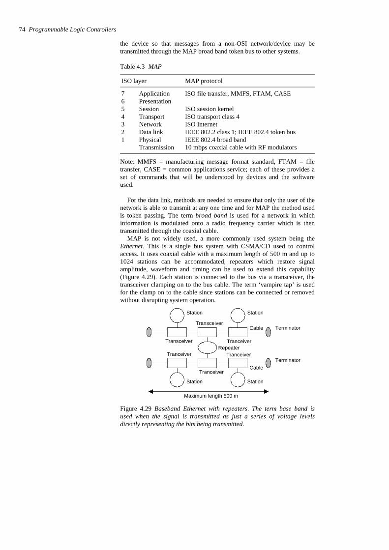
the device so that messages from a non-OSI network/device may betransmitted through the MAP broad band token bus to other systems.
Table 4.3 MAP
10 mbps coaxial cable with RF modulatorsTransmissionIEEE 802.4 broad bandPhysical1IEEE 802.2 class 1; IEEE 802.4 token busData link2ISO InternetNetwork3ISO transport class 4Transport4ISO session kernelSession5
Presentation6ISO file transfer, MMFS, FTAM, CASEApplication7
MAP protocolISO layer
Note: MMFS = manufacturing message format standard, FTAM = filetransfer, CASE = common applications service; each of these provides aset of commands that will be understood by devices and the softwareused.
For the data link, methods are needed to ensure that only the user of thenetwork is able to transmit at any one time and for MAP the method usedis token passing. The term broad band is used for a network in whichinformation is modulated onto a radio frequency carrier which is thentransmitted through the coaxial cable.
MAP is not widely used, a more commonly used system being theEthernet. This is a single bus system with CSMA/CD used to controlaccess. It uses coaxial cable with a maximum length of 500 m and up to1024 stations can be accommodated, repeaters which restore signalamplitude, waveform and timing can be used to extend this capability(Figure 4.29). Each station is connected to the bus via a transceiver, thetransceiver clamping on to the bus cable. The term ‘vampire tap’ is usedfor the clamp on to the cable since stations can be connected or removedwithout disrupting system operation.
Station Station
Station Station
Terminator
Repeater
Transceiver
Transceiver
Cable
CableTerminator
Maximum length 500 m
Tranceiver
Tranceiver
Tranceiver
Tranceiver
Figure 4.29 Baseband Ethernet with repeaters. The term base band isused when the signal is transmitted as just a series of voltage levelsdirectly representing the bits being transmitted.
74 Programmable Logic Controllers
Ethernet does not have a master station, each connected station beingof equal status and so we have peer-to-peer communication. A stationwishing to send a message on the bus will determine whether the bus isclear and, when it is, put its message frame on the bus. There is the slightprobability that more than one station will sense an idle bus and attempt totransmit. Thus each sender monitors the bus during transmission anddetects when the signal on the bus does not match its own output. Whensuch a ’collision’ is detected, the transmission continues for a short whilein order to give time to other stations to detect the collision and thenattempts to retransmit at a later time. Each message includes a bitsequence to indicate the destination address, source address, the data to betransmitted and a message check sequence. The message check sequencecontains the cycle redundancy check (see Section 4.3.4). At eachreceiving station the frame’s destination address is checked to determinewhether the frame is destined for it. If so, it accepts the message. Ethernetis widely used where systems involve PLCs having to communicate withcomputers. The modular Allen-Bradley PLC-5 can be configured for usewith a range of communication networks by the addition of suitablemodules (see Figure 1.15), a module enabling use with Ethernet.
PLC manufacturers often have their own networks, in addition togenerally offering the possibility of Ethernet. The Allen-Bradley datahighway is a peer-to-peer system developed for Allen-Bradley PLCs anduses token passing to control message transmission. The station addressesof each PLC are set by switches on each PLC. Communication isestablished by a single message on the data highway, this specifying thesending and receiving addresses and the length of block to be transferred.
4.5 Processing inputs A PLC is continuously running through its program and updating it as aresult of the input signals. Each such loop is termed a cycle. PLCs couldbe operated by each input being examined as it occurred in the programand its effect on the program determined and the output correspondinglychanged. This mode of operation is termed continuous updating.
Because, with continuous updating, there is time spent interrogatingeach input in turn, the time taken to examine several hundred input/outputpoints can become comparatively long. To allow a more rapid executionof a program, a specific area of RAM is used as a buffer store between thecontrol logic and the input/output unit. Each input/output has an addressin this memory. At the start of each program cycle the CPU scans all theinputs and copies their status into the input/output addresses in RAM. Asthe program is executed the stored input data is read, as required, fromRAM and the logic operations carried out. The resulting output signals arestored in the reserved input/output section of RAM. At the end of eachprogram cycle all the outputs are transferred from RAM to the appropriateoutput channels. The outputs then retain their status until the nextupdating. This method of operation is termed mass I/O copying. Thesequence can be summarised as (Figure 4.30):
1 Scan all the inputs and copy into RAM2 Fetch and decode and execute all program instructions in sequence,
copying output instructions to RAM
I/O processing 75
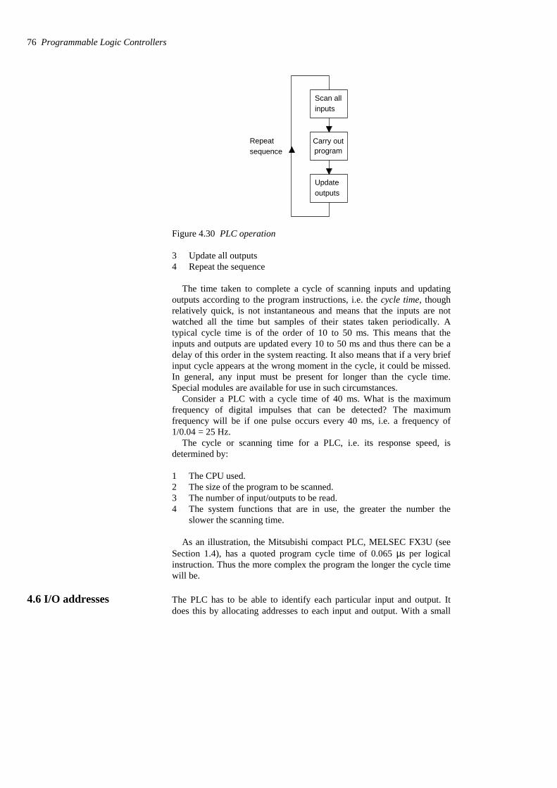
Scan allinputs
Updateoutputs
Carry outprogram
Repeatsequence
Figure 4.30 PLC operation
3 Update all outputs4 Repeat the sequence
The time taken to complete a cycle of scanning inputs and updatingoutputs according to the program instructions, i.e. the cycle time, thoughrelatively quick, is not instantaneous and means that the inputs are notwatched all the time but samples of their states taken periodically. Atypical cycle time is of the order of 10 to 50 ms. This means that theinputs and outputs are updated every 10 to 50 ms and thus there can be adelay of this order in the system reacting. It also means that if a very briefinput cycle appears at the wrong moment in the cycle, it could be missed.In general, any input must be present for longer than the cycle time.Special modules are available for use in such circumstances.
Consider a PLC with a cycle time of 40 ms. What is the maximumfrequency of digital impulses that can be detected? The maximumfrequency will be if one pulse occurs every 40 ms, i.e. a frequency of1/0.04 = 25 Hz.
The cycle or scanning time for a PLC, i.e. its response speed, isdetermined by:
1 The CPU used.2 The size of the program to be scanned.3 The number of input/outputs to be read.4 The system functions that are in use, the greater the number the
slower the scanning time.
As an illustration, the Mitsubishi compact PLC, MELSEC FX3U (seeSection 1.4), has a quoted program cycle time of 0.065 µs per logicalinstruction. Thus the more complex the program the longer the cycle timewill be.
4.6 I/O addresses The PLC has to be able to identify each particular input and output. Itdoes this by allocating addresses to each input and output. With a small
76 Programmable Logic Controllers
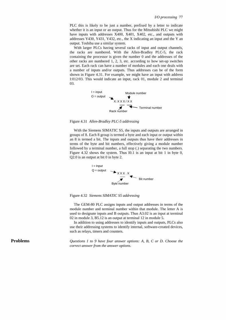
PLC this is likely to be just a number, prefixed by a letter to indicatewhether it is an input or an output. Thus for the Mitsubishi PLC we mighthave inputs with addresses X400, X401, X402, etc., and outputs withaddresses Y430, Y431, Y432, etc., the X indicating an input and the Y anoutput. Toshiba use a similar system.
With larger PLCs having several racks of input and output channels,the racks are numbered. With the Allen-Bradley PLC-5, the rackcontaining the processor is given the number 0 and the addresses of theother racks are numbered 1, 2, 3, etc. according to how set-up switchesare set. Each rack can have a number of modules and each one deals witha number of inputs and/or outputs. Thus addresses can be of the formshown in Figure 4.31. For example, we might have an input with addressI:012/03. This would indicate an input, rack 01, module 2 and terminal03.
X: X X X / X X
I = inputO = output
Rack number
Module number
Terminal number
Figure 4.31 Allen-Bradley PLC-5 addressing
With the Siemens SIMATIC S5, the inputs and outputs are arranged ingroups of 8. Each 8 group is termed a byte and each input or output withinan 8 is termed a bit. The inputs and outputs thus have their addresses interms of the byte and bit numbers, effectively giving a module numberfollowed by a terminal number, a full stop (.) separating the two numbers.Figure 4.32 shows the system. Thus I0.1 is an input at bit 1 in byte 0,Q2.0 is an output at bit 0 in byte 2.
X X X . X
I = inputQ = output
Byte numberBit number
Figure 4.32 Siemens SIMATIC S5 addressing
The GEM-80 PLC assigns inputs and output addresses in terms of themodule number and terminal number within that module. The letter A isused to designate inputs and B outputs. Thus A3.02 is an input at terminal02 in module 3, B5.12 is an output at terminal 12 in module 5.
In addition to using addresses to identify inputs and outputs, PLCs alsouse their addressing systems to identify internal, software-created devices,such as relays, timers and counters.
Problems Questions 1 to 9 have four answer options: A, B, C or D. Choose thecorrect answer from the answer options.
I/O processing 77

1 Decide whether each of these statements is True (T) or False (F).
A serial communication interface:(i) Involves data being transmitted and received one bit at a time.(ii) Is a faster form of transmission than parallel communication.
A (i) T (ii) TB (i) T (ii) FC (i) F (ii) TD (i) F (ii) F
2 Decide whether each of these statements is True (T) or False (F).
The RS232 communications interface:(i) Is a serial interface.(ii) Is typically used for distances up to about 15 m.
A (i) T (ii) TB (i) T (ii) FC (i) F (ii) TD (i) F (ii) F
Problems 3 and 4 refer to the following which shows the bits on anRS232 data line being used to transmit the data 1100001:
0110000111X YZ
3 Decide whether each of these statements is True (T) or False (F).
The extra bits X and Z at the beginning and the end are:(i) To check whether the message is corrupted during transmission.(ii) To indicate where the data starts and stops.
A (i) T (ii) TB (i) T (ii) FC (i) F (ii) TD (i) F (ii) F
4 Decide whether each of these statements is True (T) or False (F).
Bit Y is:(i) The parity bit showing odd parity.(ii) The parity bit showing even parity.
A (i) T (ii) TB (i) T (ii) FC (i) F (ii) TD (i) F (ii) F
5 Decide whether each of these statements is True (T) or False (F).
The parallel data communication interface:(i) Enables data to be transmitted over short distances at high
speeds.(ii) A common standard is IEEE-488.
78 Programmable Logic Controllers

A (i) T (ii) TB (i) T (ii) FC (i) F (ii) TD (i) F (ii) F
6 Decide whether each of these statements is True (T) or False (F).
For communications over distances of the order of 100 to 300 m witha high transmission rate:(i) The RS232 interface can be used.(ii) The 20 mA current loop can be used.
A (i) T (ii) TB (i) T (ii) FC (i) F (ii) TD (i) F (ii) F
7 Decide whether each of these statements is True (T) or False (F).
With input/output processing, mass input/output copying:(i) Scans all the inputs and copies their states into RAM.(ii) Is a faster process than continuous updating.
A (i) T (ii) TB (i) T (ii) FC (i) F (ii) TD (i) F (ii) F
8 The cycle time of a PLC is the time it takes to:
A Read an input signal.B Read all the input signals.C Check all the input signals against the program.D Read all the inputs, run the program and update all outputs.
9 Decide whether each of these statements is True (T) or False (F).
A PLC with a long cycle time is suitable for:(i) Short duration inputs.(ii) High frequency inputs.
A (i) T (ii) TB (i) T (ii) FC (i) F (ii) TD (i) F (ii) F
10 Specify (a) the odd parity bit, (b) the even parity bit, to be used whenthe data 1010100 is transmitted.
11 Explain the purpose of using a parity bit.
12 Explain the continuous updating and the mass input/output copyingmethods of processing inputs/outputs.
I/O processing 79
5 Ladder and functional block programming
Programs for microprocessor-based systems have to be loaded into themin machine code, this being a sequence of binary code numbers torepresent the program instructions. However, assembly language based onthe use of mnemonics can be used, e.g. LD is used to indicate theoperation required to load the data that follows the LD, and a computerprogram called an assembler is used to translate the mnemonics intomachine code. Programming can be made even easier by the use of theso-called high level languages, e.g. C, BASIC, PASCAL, FORTRAN,COBOL. These use pre-packaged functions, represented by simple wordsor symbols descriptive of the function concerned. For example, with Clanguage the symbol & is used for the logic AND operation. However, theuse of these methods to write programs requires some skill inprogramming and PLCs are intended to be used by engineers without anygreat knowledge of programming. As a consequence, ladderprogramming was developed. This is a means of writing programs whichcan then be converted into machine code by some software for use by thePLC microprocessor.
This method of writing programs became adopted by most PLCmanufacturers, however each tended to have developed their own versionsand so an international standard has been adopted for ladder programmingand indeed all the methods used for programming PLCs. The standard,published in 1993, is IEC 1131-3 (International ElectrotechnicalCommission). The IEC 1131-3 programming languages are ladderdiagrams (LAD), instruction list (IL), sequential function charts (SFC),structured text (ST), and function block diagrams (FBD).
This chapter is an introduction to the programming of a PLC usingladder diagrams and functional block diagrams, with discussion of theother techniques in the next chapter. Here we are concerned with the basictechniques involved in developing ladder and function block programs torepresent basic switching operations, involving the logic functions ofAND, OR, Exclusive OR, NAND and NOR, and latching. Later chapterscontinue with further ladder programming involving other elements.
5.1 Ladder diagrams As an introduction to ladder diagrams, consider the simple wiring diagramfor an electrical circuit in Figure 5.1(a). The diagram shows the circuit forswitching on or off an electric motor. We can redraw this diagram in adifferent way, using two vertical lines to represent the input power railsand stringing the rest of the circuit between them. Figure 5.1(b) shows theresult. Both circuits have the switch in series with the motor and supplied
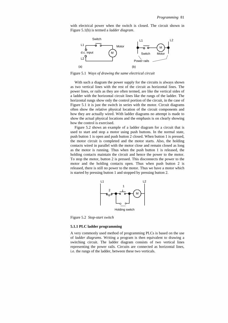
with electrical power when the switch is closed. The circuit shown inFigure 5.1(b) is termed a ladder diagram.
Md.c. input
Switch
Motor
(a)
L1
L2Power rails
L1 L2
Switch Motor
M
(b)
Figure 5.1 Ways of drawing the same electrical circuit
With such a diagram the power supply for the circuits is always shownas two vertical lines with the rest of the circuit as horizontal lines. Thepower lines, or rails as they are often termed, are like the vertical sides ofa ladder with the horizontal circuit lines like the rungs of the ladder. Thehorizontal rungs show only the control portion of the circuit, in the case ofFigure 5.1 it is just the switch in series with the motor. Circuit diagramsoften show the relative physical location of the circuit components andhow they are actually wired. With ladder diagrams no attempt is made toshow the actual physical locations and the emphasis is on clearly showinghow the control is exercised.
Figure 5.2 shows an example of a ladder diagram for a circuit that isused to start and stop a motor using push buttons. In the normal state,push button 1 is open and push button 2 closed. When button 1 is pressed,the motor circuit is completed and the motor starts. Also, the holdingcontacts wired in parallel with the motor close and remain closed as longas the motor is running. Thus when the push button 1 is released, theholding contacts maintain the circuit and hence the power to the motor.To stop the motor, button 2 is pressed. This disconnects the power to themotor and the holding contacts open. Thus when push button 2 isreleased, there is still no power to the motor. Thus we have a motor whichis started by pressing button 1 and stopped by pressing button 2.
L1 L2
M
12
Holding switch
Figure 5.2 Stop-start switch
5.1.1 PLC ladder programming
A very commonly used method of programming PLCs is based on the useof ladder diagrams. Writing a program is then equivalent to drawing aswitching circuit. The ladder diagram consists of two vertical linesrepresenting the power rails. Circuits are connected as horizontal lines,i.e. the rungs of the ladder, between these two verticals.
Programming 81
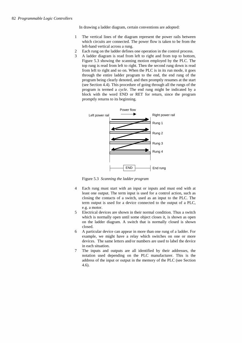
In drawing a ladder diagram, certain conventions are adopted:
1 The vertical lines of the diagram represent the power rails betweenwhich circuits are connected. The power flow is taken to be from theleft-hand vertical across a rung.
2 Each rung on the ladder defines one operation in the control process.3 A ladder diagram is read from left to right and from top to bottom,
Figure 5.3 showing the scanning motion employed by the PLC. Thetop rung is read from left to right. Then the second rung down is readfrom left to right and so on. When the PLC is in its run mode, it goesthrough the entire ladder program to the end, the end rung of theprogram being clearly denoted, and then promptly resumes at the start(see Section 4.4). This procedure of going through all the rungs of theprogram is termed a cycle. The end rung might be indicated by ablock with the word END or RET for return, since the programpromptly returns to its beginning.
Rung 1
Rung 2
Rung 3
Rung 4
END End rung
Left power rail Right power railPower flow
Figure 5.3 Scanning the ladder program
4 Each rung must start with an input or inputs and must end with atleast one output. The term input is used for a control action, such asclosing the contacts of a switch, used as an input to the PLC. Theterm output is used for a device connected to the output of a PLC,e.g. a motor.
5 Electrical devices are shown in their normal condition. Thus a switchwhich is normally open until some object closes it, is shown as openon the ladder diagram. A switch that is normally closed is shownclosed.
6 A particular device can appear in more than one rung of a ladder. Forexample, we might have a relay which switches on one or moredevices. The same letters and/or numbers are used to label the devicein each situation.
7 The inputs and outputs are all identified by their addresses, thenotation used depending on the PLC manufacturer. This is theaddress of the input or output in the memory of the PLC (see Section4.6).
82 Programmable Logic Controllers
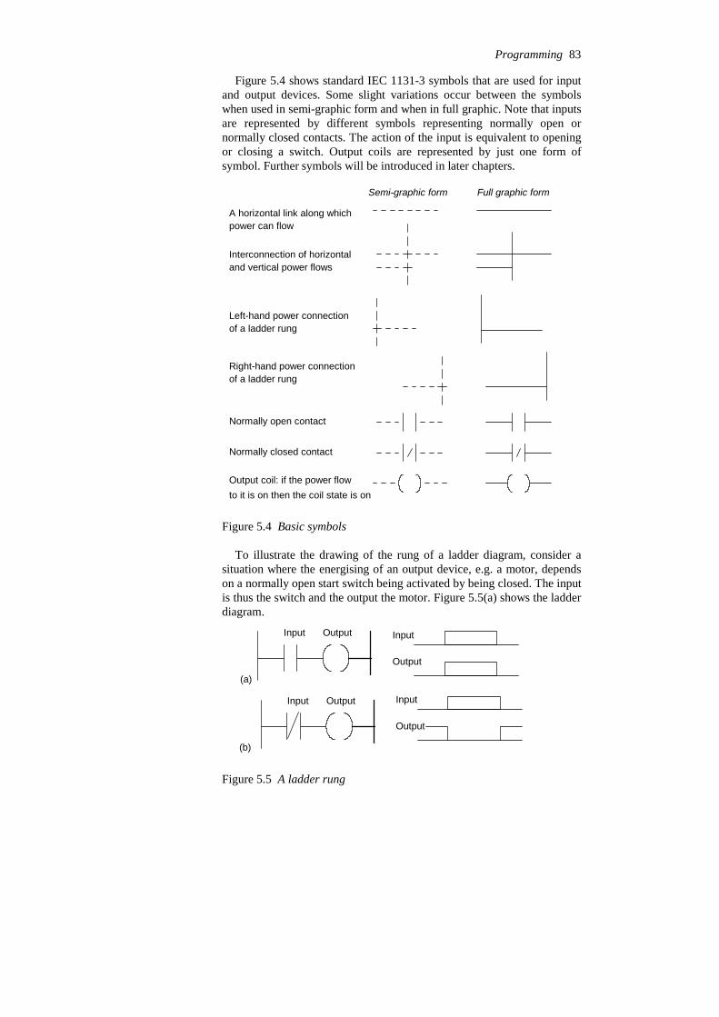
Figure 5.4 shows standard IEC 1131-3 symbols that are used for inputand output devices. Some slight variations occur between the symbolswhen used in semi-graphic form and when in full graphic. Note that inputsare represented by different symbols representing normally open ornormally closed contacts. The action of the input is equivalent to openingor closing a switch. Output coils are represented by just one form ofsymbol. Further symbols will be introduced in later chapters.
Semi-graphic form Full graphic form
A horizontal link along whichpower can flow
Interconnection of horizontaland vertical power flows
Left-hand power connectionof a ladder rung
Right-hand power connectionof a ladder rung
Normally open contact
Normally closed contact
Output coil: if the power flowto it is on then the coil state is on
Figure 5.4 Basic symbols
To illustrate the drawing of the rung of a ladder diagram, consider asituation where the energising of an output device, e.g. a motor, dependson a normally open start switch being activated by being closed. The inputis thus the switch and the output the motor. Figure 5.5(a) shows the ladderdiagram.
OutputInput
(a)
Input
Output
OutputInput
(b)
Input
Output
Figure 5.5 A ladder rung
Programming 83
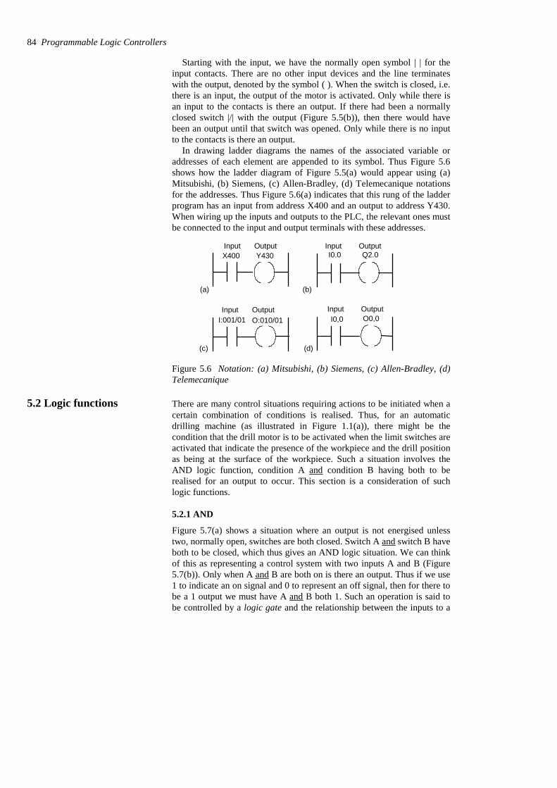
Starting with the input, we have the normally open symbol | | for theinput contacts. There are no other input devices and the line terminateswith the output, denoted by the symbol ( ). When the switch is closed, i.e.there is an input, the output of the motor is activated. Only while there isan input to the contacts is there an output. If there had been a normallyclosed switch |/| with the output (Figure 5.5(b)), then there would havebeen an output until that switch was opened. Only while there is no inputto the contacts is there an output.
In drawing ladder diagrams the names of the associated variable oraddresses of each element are appended to its symbol. Thus Figure 5.6shows how the ladder diagram of Figure 5.5(a) would appear using (a)Mitsubishi, (b) Siemens, (c) Allen-Bradley, (d) Telemecanique notationsfor the addresses. Thus Figure 5.6(a) indicates that this rung of the ladderprogram has an input from address X400 and an output to address Y430.When wiring up the inputs and outputs to the PLC, the relevant ones mustbe connected to the input and output terminals with these addresses.
X400 Y430 I0.0 Q2.0Input Output Input Output
I:001/01 O:010/01Input Output
I0,0 O0,0Input Output
(a) (b)
(c) (d)
Figure 5.6 Notation: (a) Mitsubishi, (b) Siemens, (c) Allen-Bradley, (d)Telemecanique
5.2 Logic functions There are many control situations requiring actions to be initiated when acertain combination of conditions is realised. Thus, for an automaticdrilling machine (as illustrated in Figure 1.1(a)), there might be thecondition that the drill motor is to be activated when the limit switches areactivated that indicate the presence of the workpiece and the drill positionas being at the surface of the workpiece. Such a situation involves theAND logic function, condition A and condition B having both to berealised for an output to occur. This section is a consideration of suchlogic functions.
5.2.1 AND
Figure 5.7(a) shows a situation where an output is not energised unlesstwo, normally open, switches are both closed. Switch A and switch B haveboth to be closed, which thus gives an AND logic situation. We can thinkof this as representing a control system with two inputs A and B (Figure5.7(b)). Only when A and B are both on is there an output. Thus if we use1 to indicate an on signal and 0 to represent an off signal, then for there tobe a 1 output we must have A and B both 1. Such an operation is said tobe controlled by a logic gate and the relationship between the inputs to a
84 Programmable Logic Controllers
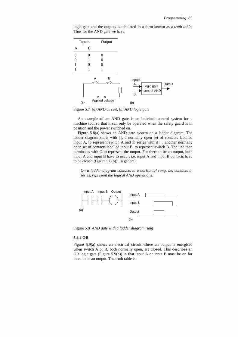
logic gate and the outputs is tabulated in a form known as a truth table.Thus for the AND gate we have:
11 1 0 0 1 0 1 0 0 0 0
BAOutputInputs
A B
Applied voltage
Logic gatecontrol AND
A
B
OutputInputs
(a) (b)
Figure 5.7 (a) AND circuit, (b) AND logic gate
An example of an AND gate is an interlock control system for amachine tool so that it can only be operated when the safety guard is inposition and the power switched on.
Figure 5.8(a) shows an AND gate system on a ladder diagram. Theladder diagram starts with | |, a normally open set of contacts labelledinput A, to represent switch A and in series with it | |, another normallyopen set of contacts labelled input B, to represent switch B. The line thenterminates with O to represent the output. For there to be an output, bothinput A and input B have to occur, i.e. input A and input B contacts haveto be closed (Figure 5.8(b)). In general:
On a ladder diagram contacts in a horizontal rung, i.e. contacts inseries, represent the logical AND operations.
Input A Input B Output
(a)
(b)
Input A
Input B
Output
Figure 5.8 AND gate with a ladder diagram rung
5.2.2 OR
Figure 5.9(a) shows an electrical circuit where an output is energisedwhen switch A or B, both normally open, are closed. This describes anOR logic gate (Figure 5.9(b)) in that input A or input B must be on forthere to be an output. The truth table is:
Programming 85

11 1 1 0 1 1 1 0 0 0 0
BAOutput Inputs
A
B
Applied voltage
Logic gatecontrol OR
A
B
OutputInputs
(b)(a)
Figure 5.9 (a) OR electrical circuit, (b) OR logic gate
Figure 5.10(a) shows an OR logic gate system on a ladder diagram,Figure 5.10(b) showing an equivalent alternative way of drawing the samediagram. The ladder diagram starts with | |, normally open contactslabelled input A, to represent switch A and in parallel with it | |, normallyopen contacts labelled input B, to represent switch B. Either input A orinput B have to be closed for the output to be energised (Figure 5.10(c)).The line then terminates with O to represent the output. In general:
Alternative paths provided by vertical paths from the main rung of aladder diagram, i.e. paths in parallel, represent logical ORoperations.
Input A
Input B
Output Input A Output
Input B
(a) (b)
Input A
Input B
Output(c)
Figure 5.10 OR gate
An example of an OR gate control system is a conveyor belttransporting bottled products to packaging where a deflector plate isactivated to deflect bottles into a reject bin if either the weight is notwithin certain tolerances or there is no cap on the bottle.
86 Programmable Logic Controllers
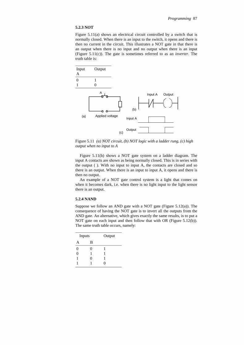
5.2.3 NOT
Figure 5.11(a) shows an electrical circuit controlled by a switch that isnormally closed. When there is an input to the switch, it opens and there isthen no current in the circuit. This illustrates a NOT gate in that there isan output when there is no input and no output when there is an input(Figure 5.11(c)). The gate is sometimes referred to as an inverter. Thetruth table is:
0 1 1 0
OutputInputA
A
Applied voltage(a)
Input A Output
(b)
Input A
Output(c)
Figure 5.11 (a) NOT circuit, (b) NOT logic with a ladder rung, (c) highoutput when no input to A
Figure 5.11(b) shows a NOT gate system on a ladder diagram. Theinput A contacts are shown as being normally closed. This is in series withthe output ( ). With no input to input A, the contacts are closed and sothere is an output. When there is an input to input A, it opens and there isthen no output.
An example of a NOT gate control system is a light that comes onwhen it becomes dark, i.e. when there is no light input to the light sensorthere is an output.
5.2.4 NAND
Suppose we follow an AND gate with a NOT gate (Figure 5.12(a)). Theconsequence of having the NOT gate is to invert all the outputs from theAND gate. An alternative, which gives exactly the same results, is to put aNOT gate on each input and then follow that with OR (Figure 5.12(b)).The same truth table occurs, namely:
0 1 1 1 0 1 1 1 0 1 0 0
BAOutput Inputs
Programming 87

AND NOT
NOT
NOT
OR
A
B
A
B
(a) (b)
Figure 5.12 NAND gate
Both the inputs A and B have to be 0 for there to be a 1 output. There isan output when input A and input B are not 1. The combination of thesegates is termed a NAND gate.
Input A
Input B
OutputInput A
Input B
Output
Figure 5.13 A NAND gate
Figure 4.18 shows a ladder diagram which gives a NAND gate. Whenthe inputs to input A and input B are both 0 then the output is 1. When theinputs to input A and input B are both 1, or one is 0 and the other 1, thenthe output is 0.
An example of a NAND gate control system is a warning light thatcomes on if, with a machine tool, the safety guard switch has not beenactivated and the limit switch signalling the presence of the workpiece hasnot been activated.
5.2.5 NOR
Suppose we follow an OR gate by a NOT gate (Figure 5.14(a)). Theconsequence of having the NOT gate is to invert the outputs of the ORgate. An alternative, which gives exactly the same results, is to put a NOTgate on each input and then an AND gate for the resulting inverted inputs(Figure 5.14(b)). The following is the resulting truth table:
01 1 0 0 1 0 1 0 1 0 0
BAOutput Inputs
The combination of OR and NOT gates is termed a NOR gate. There is anoutput when neither input A or input B is 1.
88 Programmable Logic Controllers
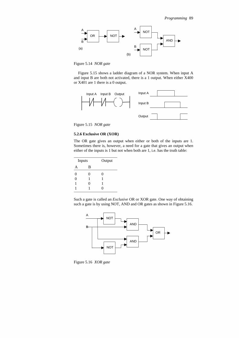
OR NOTNOT
NOT
AND
A
B
A
B(a)
(b)
Figure 5.14 NOR gate
Figure 5.15 shows a ladder diagram of a NOR system. When input Aand input B are both not activated, there is a 1 output. When either X400or X401 are 1 there is a 0 output.
Input A Input B Output Input A
Input B
Output
Figure 5.15 NOR gate
5.2.6 Exclusive OR (XOR)
The OR gate gives an output when either or both of the inputs are 1.Sometimes there is, however, a need for a gate that gives an output wheneither of the inputs is 1 but not when both are 1, i.e. has the truth table:
01 1 1 0 1 1 1 0 0 0 0
B A Output Inputs
Such a gate is called an Exclusive OR or XOR gate. One way of obtainingsuch a gate is by using NOT, AND and OR gates as shown in Figure 5.16.
A
B
NOT
NOT
AND
AND
OR
Figure 5.16 XOR gate
Programming 89
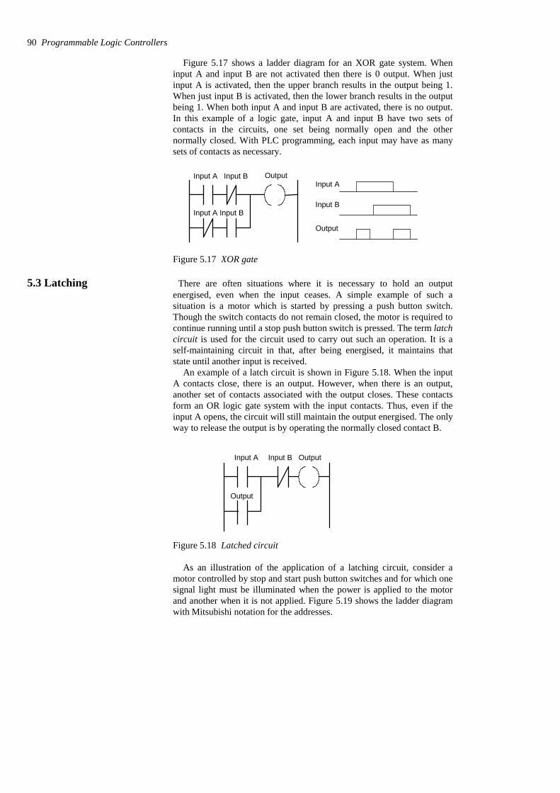
Figure 5.17 shows a ladder diagram for an XOR gate system. Wheninput A and input B are not activated then there is 0 output. When justinput A is activated, then the upper branch results in the output being 1.When just input B is activated, then the lower branch results in the outputbeing 1. When both input A and input B are activated, there is no output.In this example of a logic gate, input A and input B have two sets ofcontacts in the circuits, one set being normally open and the othernormally closed. With PLC programming, each input may have as manysets of contacts as necessary.
OutputInput A Input B
Input A Input B
Input A
Input B
Output
Figure 5.17 XOR gate
5.3 Latching There are often situations where it is necessary to hold an outputenergised, even when the input ceases. A simple example of such asituation is a motor which is started by pressing a push button switch.Though the switch contacts do not remain closed, the motor is required tocontinue running until a stop push button switch is pressed. The term latchcircuit is used for the circuit used to carry out such an operation. It is aself-maintaining circuit in that, after being energised, it maintains thatstate until another input is received.
An example of a latch circuit is shown in Figure 5.18. When the inputA contacts close, there is an output. However, when there is an output,another set of contacts associated with the output closes. These contactsform an OR logic gate system with the input contacts. Thus, even if theinput A opens, the circuit will still maintain the output energised. The onlyway to release the output is by operating the normally closed contact B.
Input A Input B Output
Output
Figure 5.18 Latched circuit
As an illustration of the application of a latching circuit, consider amotor controlled by stop and start push button switches and for which onesignal light must be illuminated when the power is applied to the motorand another when it is not applied. Figure 5.19 shows the ladder diagramwith Mitsubishi notation for the addresses.
90 Programmable Logic Controllers
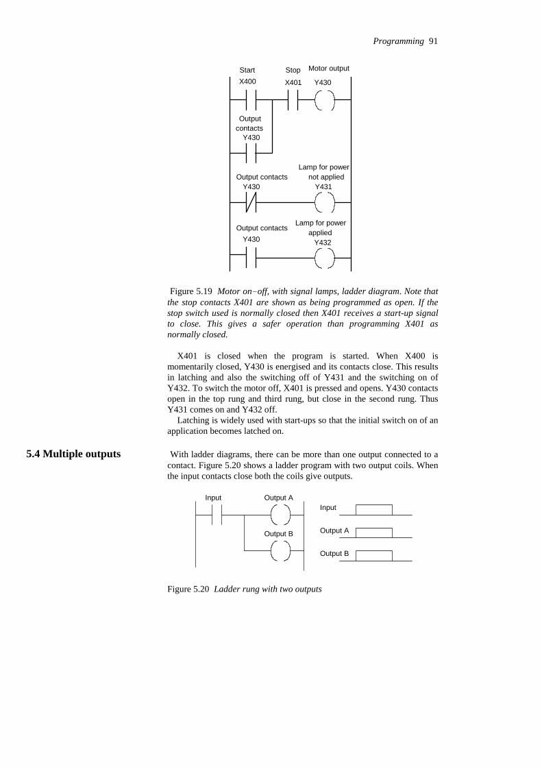
X400 X401 Y430
Y430
Y430 Y431
Y430 Y432
Motor output
Lamp for power
Lamp for power
not applied
applied
Start Stop
Output contacts
Output contacts
Outputcontacts
Figure 5.19 Motor on-off, with signal lamps, ladder diagram. Note thatthe stop contacts X401 are shown as being programmed as open. If thestop switch used is normally closed then X401 receives a start-up signalto close. This gives a safer operation than programming X401 asnormally closed.
X401 is closed when the program is started. When X400 ismomentarily closed, Y430 is energised and its contacts close. This resultsin latching and also the switching off of Y431 and the switching on ofY432. To switch the motor off, X401 is pressed and opens. Y430 contactsopen in the top rung and third rung, but close in the second rung. ThusY431 comes on and Y432 off.
Latching is widely used with start-ups so that the initial switch on of anapplication becomes latched on.
5.4 Multiple outputs With ladder diagrams, there can be more than one output connected to acontact. Figure 5.20 shows a ladder program with two output coils. Whenthe input contacts close both the coils give outputs.
Input Output A
Output B
Input
Output A
Output B
Figure 5.20 Ladder rung with two outputs
Programming 91

For the ladder rung shown in Figure 5.21, output A occurs when inputA occurs. Output B only occurs when both input A and input B occur.
Input A Output A
Output B
Input A
Output A
Output BInput B
Input B
Figure 5.21 Ladder rung with two inputs and two outputs
Such an arrangement enables a sequence of outputs to be produced, thesequence being in the sequence with which contacts are closed. Figure5.22 illustrates this with the same ladder program in Mitsubishi andSiemens notations. Outputs A, B and C are switched on as the contacts inthe sequence given by the contacts A, B and C are being closed. Untilinput A is closed, none of the other outputs can be switched on. Wheninput A is closed, output A is switched on. Then, when input B is closed,output B is switched on. Finally, when input C is closed, output C isswitched on.
(a)
I0.0
I0.1
I0.2
Q2.0
Q2.1
Q2.2
(b)
X400
X401
X402
Y430
Y431
Y432
Input A
Input B
Input C
Output A
Output B
Output C
Input A
Input B
Input C
Output A
Output B
Output C
Input A
Input B
Input C
Output A
Output B
Output C
Figure 5.22 Sequenced outputs
92 Programmable Logic Controllers
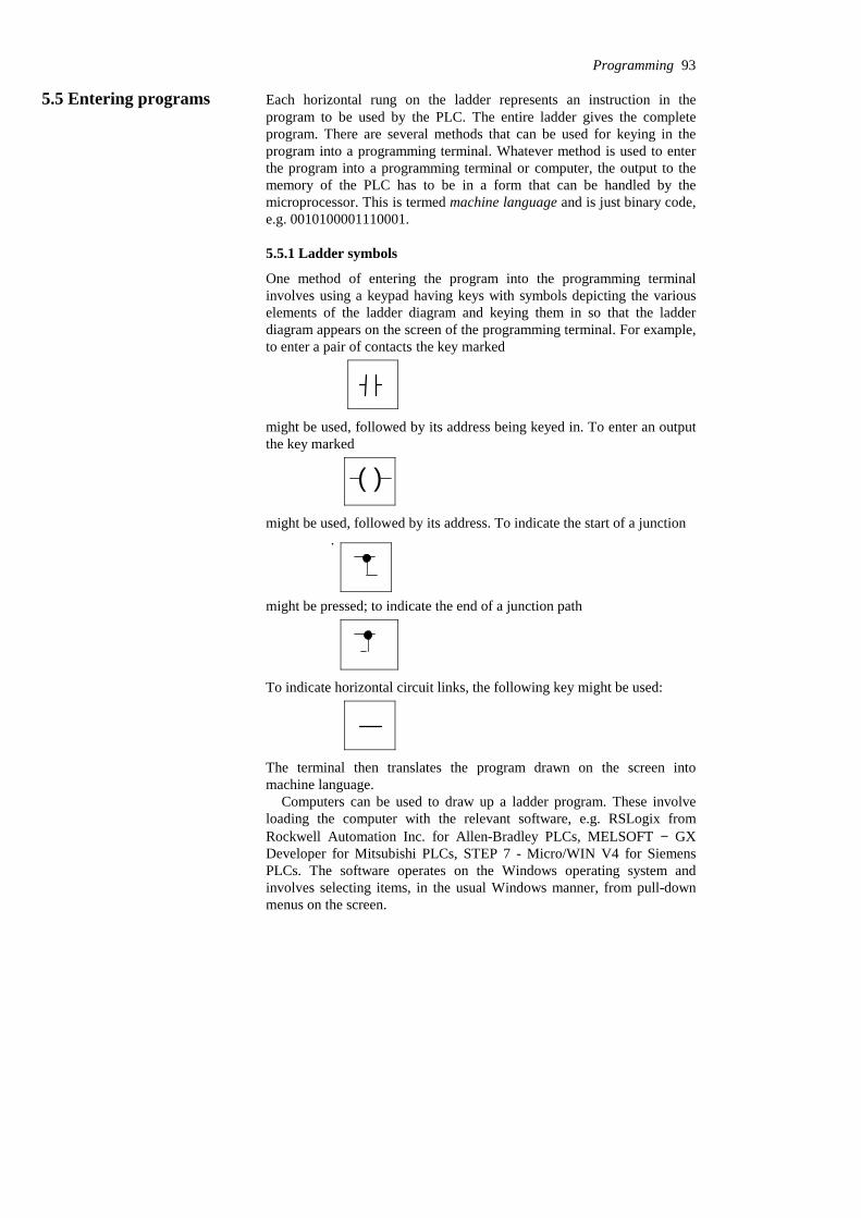
5.5 Entering programs Each horizontal rung on the ladder represents an instruction in theprogram to be used by the PLC. The entire ladder gives the completeprogram. There are several methods that can be used for keying in theprogram into a programming terminal. Whatever method is used to enterthe program into a programming terminal or computer, the output to thememory of the PLC has to be in a form that can be handled by themicroprocessor. This is termed machine language and is just binary code,e.g. 0010100001110001.
5.5.1 Ladder symbols
One method of entering the program into the programming terminalinvolves using a keypad having keys with symbols depicting the variouselements of the ladder diagram and keying them in so that the ladderdiagram appears on the screen of the programming terminal. For example,to enter a pair of contacts the key marked
might be used, followed by its address being keyed in. To enter an outputthe key marked
( )might be used, followed by its address. To indicate the start of a junction .
might be pressed; to indicate the end of a junction path
To indicate horizontal circuit links, the following key might be used:
The terminal then translates the program drawn on the screen intomachine language.
Computers can be used to draw up a ladder program. These involveloading the computer with the relevant software, e.g. RSLogix fromRockwell Automation Inc. for Allen-Bradley PLCs, MELSOFT − GXDeveloper for Mitsubishi PLCs, STEP 7 - Micro/WIN V4 for SiemensPLCs. The software operates on the Windows operating system andinvolves selecting items, in the usual Windows manner, from pull-downmenus on the screen.
Programming 93

5.6 Function blocks The term function block diagram (FBD) is used for PLC programsdescribed in terms of graphical blocks. It is described as being a graphicallanguage for depicting signal and data flows through blocks, these beingreusable software elements. A function block is a program instruction unitwhich, when executed, yields one or more output values. Thus a block isrepresented in the manner shown in Figure 5.23 with the function namewritten in the box.
InputsOutput
Function
Figure 5.23 Function block
The IEC 113-3 standard for drawing such blocks is shown in Figure5.24. A function block is depicted as a rectangular block with inputsentering from the left and outputs emerging from the right. The functionblock type name is shown in the block, e.g. AND, with the name of thefunction block in the system shown above it, Timer1. Names of functionblock inputs are shown within the block at the appropriate input andoutput points. Cross diagram connectors are used to indicate wheregraphical lines would be difficult to draw without cluttering up orcomplicating a diagram and show where an output at one point is used asan input at another.
Semi-graphic form Full graphic form
Interconnection of horizontaland vertical signal flows
Crossing horizontal andvertical signal flows
Horizontal and vertical lines
Blocks with connections
Connectors AV_WEIGHT
AV_WEIGHT
AV_WEIGHT
AV_WEIGHT
Figure 5.24 Function block diagrams representation
94 Programmable Logic Controllers
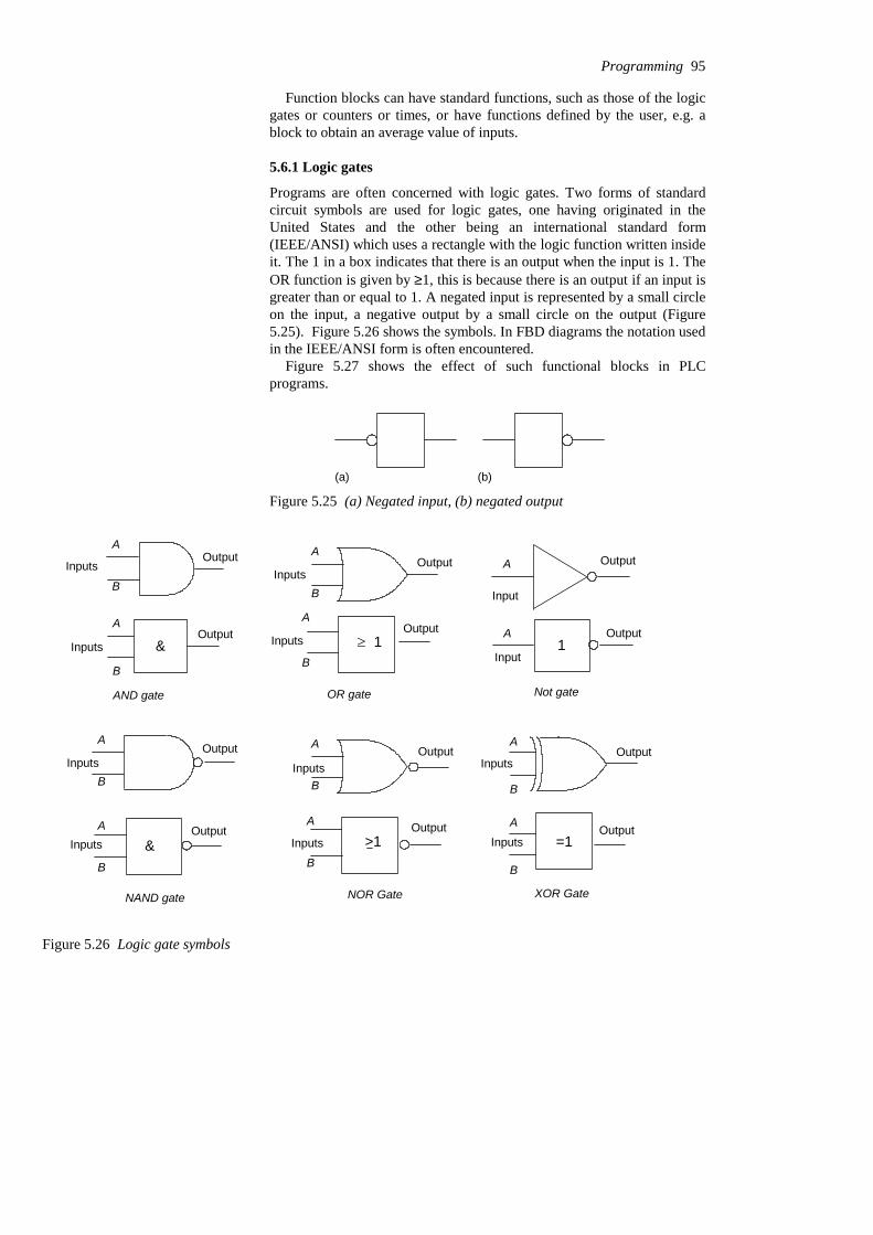
Function blocks can have standard functions, such as those of the logicgates or counters or times, or have functions defined by the user, e.g. ablock to obtain an average value of inputs.
5.6.1 Logic gates
Programs are often concerned with logic gates. Two forms of standardcircuit symbols are used for logic gates, one having originated in theUnited States and the other being an international standard form(IEEE/ANSI) which uses a rectangle with the logic function written insideit. The 1 in a box indicates that there is an output when the input is 1. TheOR function is given by ≥1, this is because there is an output if an input isgreater than or equal to 1. A negated input is represented by a small circleon the input, a negative output by a small circle on the output (Figure5.25). Figure 5.26 shows the symbols. In FBD diagrams the notation usedin the IEEE/ANSI form is often encountered.
Figure 5.27 shows the effect of such functional blocks in PLCprograms.
(a) (b)
Figure 5.25 (a) Negated input, (b) negated output
A
B
OutputInputs
OutputA
B
Inputs &
AND gate OR gate
A
B
OutputInputs
A
B
OutputInputs 1m
Not gate
Input
OutputA
Input
OutputA1
A
B
OutputInputs
A
B
OutputInputs &
NAND gate
A
B
OutputInputs
A
B
OutputInputs >1
NOR Gate XOR Gate
OutputA
B
Inputs
Output=1
A
B
Inputs
Figure 5.26 Logic gate symbols
Programming 95
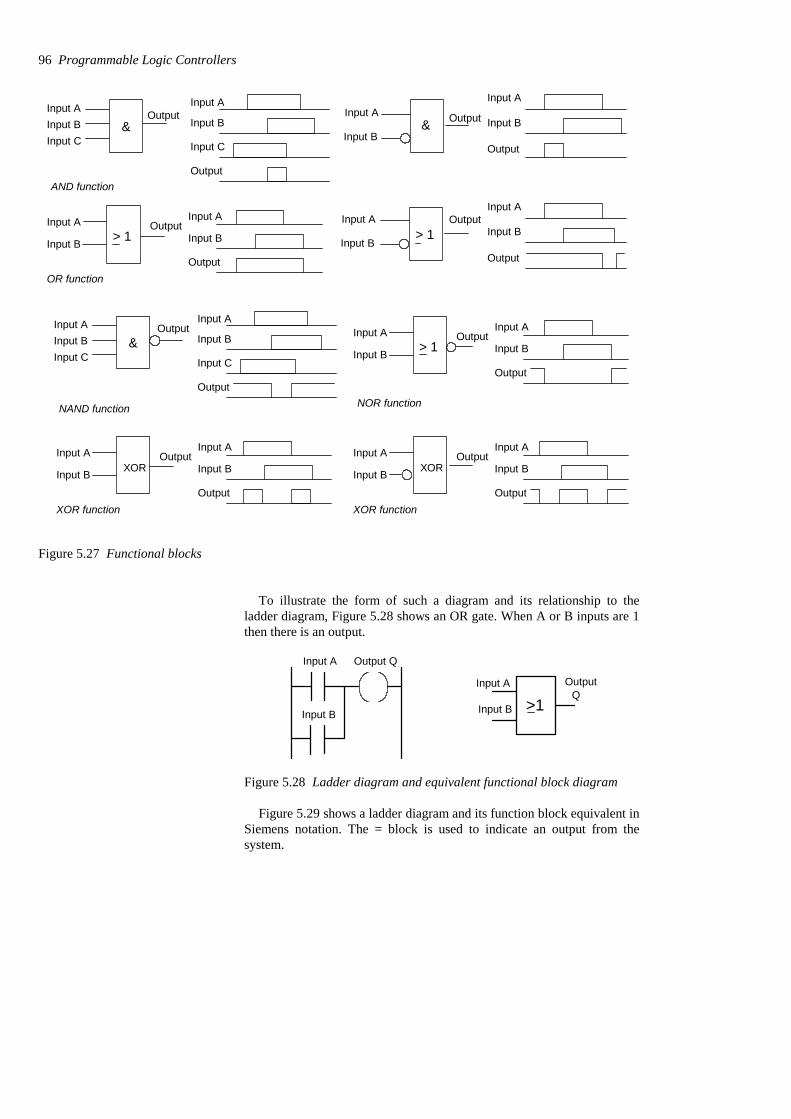
Input AInput BInput C
Output&
Input A
Input B
Input C
OutputAND function
Input A
Input B
Output> 1
OR function
Input A
Input B
Output
Input A
Input B
Output
Input A
Input B& Output
Input A
Input B
OutputInput A
Input B
Output
> 1
Input AInput BInput C
Output&
Input A
Input B
Input C
Output
NAND function
Input A
Input B
Output> 1
NOR function
Input A
Input B
Output
Input A
Input B
Output
XOR function
Input A
Input B
Output
XORInput A
Input B
Output
XOR function
Input A
Input B
Output
XOR
Figure 5.27 Functional blocks
To illustrate the form of such a diagram and its relationship to theladder diagram, Figure 5.28 shows an OR gate. When A or B inputs are 1then there is an output.
Input A Output Q
Input A
Input BQ
>1Input B
Output
Figure 5.28 Ladder diagram and equivalent functional block diagram
Figure 5.29 shows a ladder diagram and its function block equivalent inSiemens notation. The = block is used to indicate an output from thesystem.
96 Programmable Logic Controllers
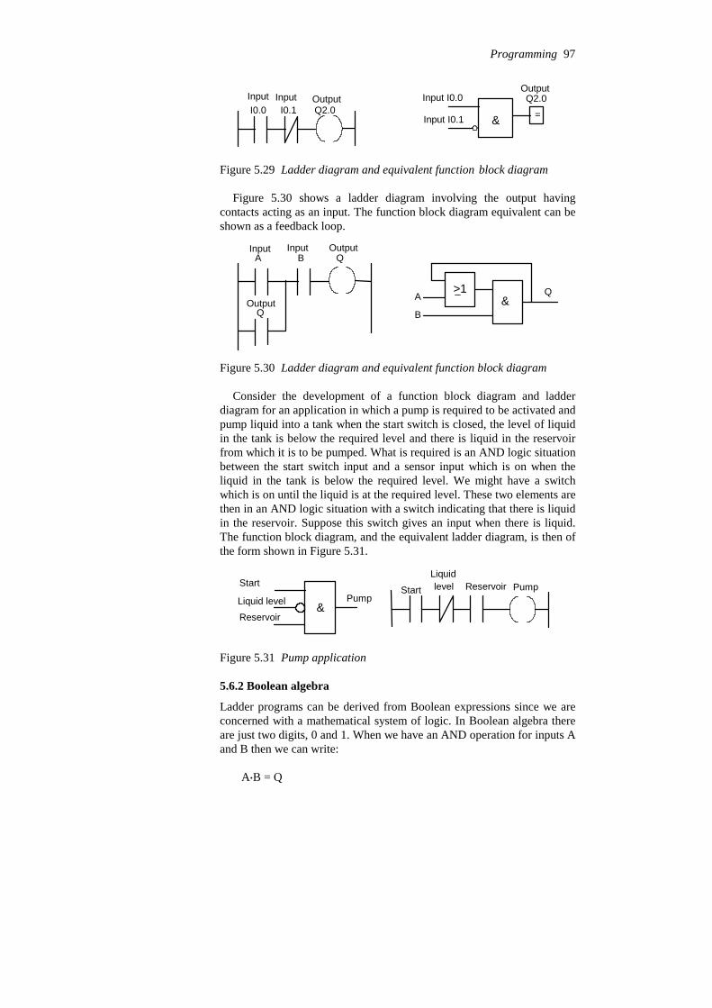
I0.0 I0.1 Q2.0Input I0.0
& =
Q2.0Input Input Output
Input I0.1
Output
Figure 5.29 Ladder diagram and equivalent function block diagram
Figure 5.30 shows a ladder diagram involving the output havingcontacts acting as an input. The function block diagram equivalent can beshown as a feedback loop.
A B
Q
Q
A
B
>1&
Q
Input Input Output
Output
Figure 5.30 Ladder diagram and equivalent function block diagram
Consider the development of a function block diagram and ladderdiagram for an application in which a pump is required to be activated andpump liquid into a tank when the start switch is closed, the level of liquidin the tank is below the required level and there is liquid in the reservoirfrom which it is to be pumped. What is required is an AND logic situationbetween the start switch input and a sensor input which is on when theliquid in the tank is below the required level. We might have a switchwhich is on until the liquid is at the required level. These two elements arethen in an AND logic situation with a switch indicating that there is liquidin the reservoir. Suppose this switch gives an input when there is liquid.The function block diagram, and the equivalent ladder diagram, is then ofthe form shown in Figure 5.31.
Reservoir
Liquid level
StartPump
Start
Liquidlevel Reservoir Pump
&
Figure 5.31 Pump application
5.6.2 Boolean algebra
Ladder programs can be derived from Boolean expressions since we areconcerned with a mathematical system of logic. In Boolean algebra thereare just two digits, 0 and 1. When we have an AND operation for inputs Aand B then we can write:
A$B = Q
Programming 97
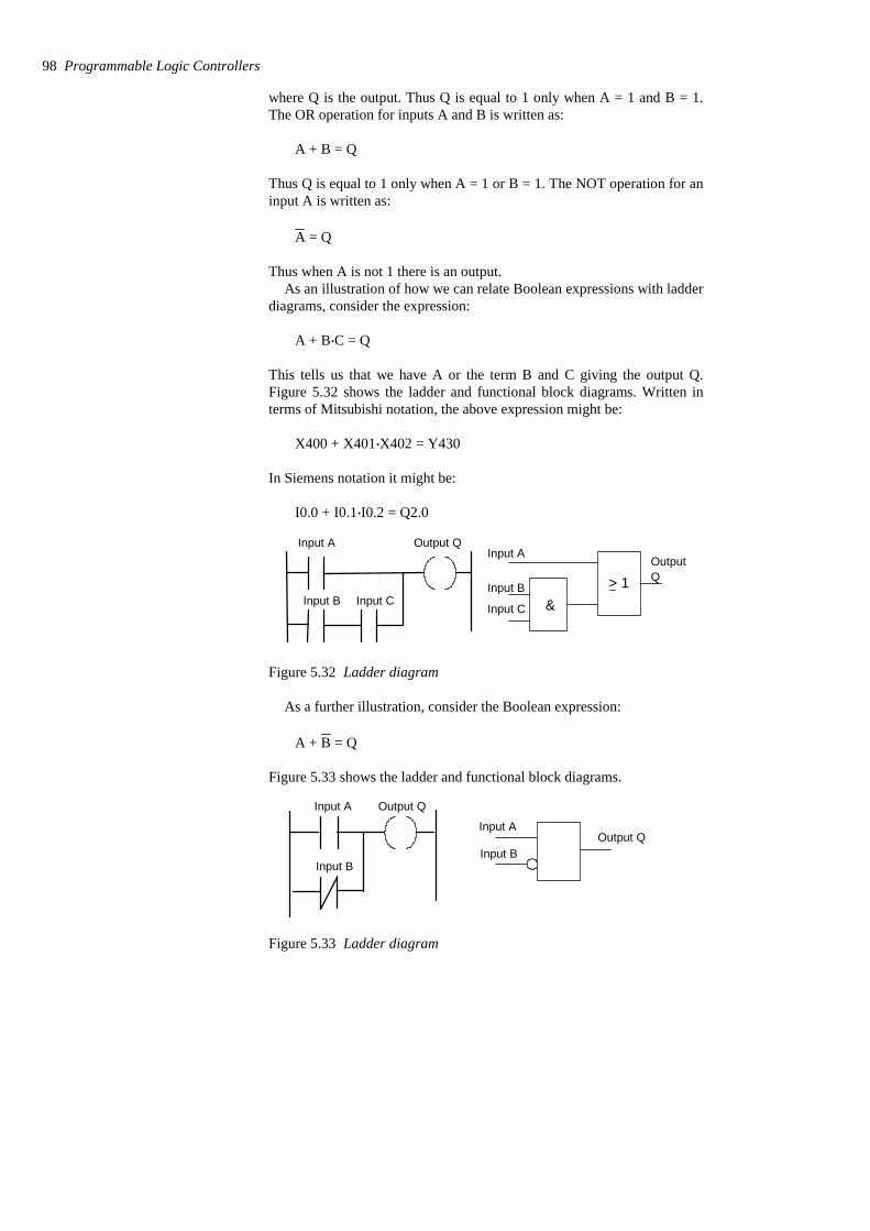
where Q is the output. Thus Q is equal to 1 only when A = 1 and B = 1.The OR operation for inputs A and B is written as:
A + B = Q
Thus Q is equal to 1 only when A = 1 or B = 1. The NOT operation for aninput A is written as:
A = Q
Thus when A is not 1 there is an output.As an illustration of how we can relate Boolean expressions with ladder
diagrams, consider the expression:
A + B$C = Q
This tells us that we have A or the term B and C giving the output Q.Figure 5.32 shows the ladder and functional block diagrams. Written interms of Mitsubishi notation, the above expression might be:
X400 + X401$X402 = Y430
In Siemens notation it might be:
I0.0 + I0.1$I0.2 = Q2.0
Input A
Input B Input C
Output QInput A
Input B
Input C
OutputQ
&> 1
Figure 5.32 Ladder diagram
As a further illustration, consider the Boolean expression:
A + B = Q
Figure 5.33 shows the ladder and functional block diagrams.
Input A
Input B
Output Q
Input A
Input BOutput Q
Figure 5.33 Ladder diagram
98 Programmable Logic Controllers

Written in terms of Mitsubishi notation, the expression might be:
X400 + X401 = Y430
and in Siemens notation:
I0.0 + I0.1 = Q2.0
Consider the exclusive-OR gate and its assembly from NOT, AND andOR gates, as shown in Figure 5.34.
Input A
Input B
1
1
> 1 Output Q
&
&
Figure 5.34 XOR gate
The input to the bottom AND gate is:
A and B
and so its output is:
A$B
The input to the top AND gate is:
A and B
and so its output is:
A $B
Thus the Boolean expression for the output from the OR gate is:
A$B + A $B = Q
Consider a logic diagram with many inputs, as shown in Figure 5.35,and its representation by a Boolean expression and a ladder rung.
Programming 99
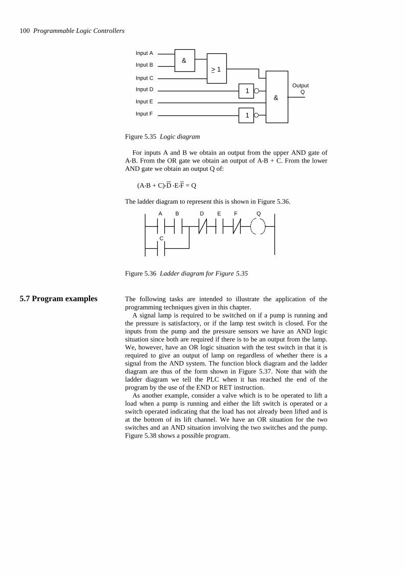
Input A
Input B
Input C
Input D
Input E
Input F
&
&Q
Output1
1
> 1
Figure 5.35 Logic diagram
For inputs A and B we obtain an output from the upper AND gate ofA$B. From the OR gate we obtain an output of A$B + C. From the lowerAND gate we obtain an output Q of:
(A$B + C)$D $E$F = Q
The ladder diagram to represent this is shown in Figure 5.36.
A B
C
D E F Q
Figure 5.36 Ladder diagram for Figure 5.35
5.7 Program examples The following tasks are intended to illustrate the application of theprogramming techniques given in this chapter.
A signal lamp is required to be switched on if a pump is running andthe pressure is satisfactory, or if the lamp test switch is closed. For theinputs from the pump and the pressure sensors we have an AND logicsituation since both are required if there is to be an output from the lamp.We, however, have an OR logic situation with the test switch in that it isrequired to give an output of lamp on regardless of whether there is asignal from the AND system. The function block diagram and the ladderdiagram are thus of the form shown in Figure 5.37. Note that with theladder diagram we tell the PLC when it has reached the end of theprogram by the use of the END or RET instruction.
As another example, consider a valve which is to be operated to lift aload when a pump is running and either the lift switch is operated or aswitch operated indicating that the load has not already been lifted and isat the bottom of its lift channel. We have an OR situation for the twoswitches and an AND situation involving the two switches and the pump.Figure 5.38 shows a possible program.
100 Programmable Logic Controllers

Pump
Pressure
Test
&>1
Pump PressureX400 X401
LampY430
X402Test
END
Figure 5.37 Signal lamp task
END
Lift
Not lifted
ValvePumpX400 X401 Y430
X402
&
Lift switch
Not lifted
Pump on
Valveswitch
> 1
Figure 5.38 Valve operation program
As another example, consider a system where there has to be no outputwhen any one of four sensors gives an output, otherwise there is to be anoutput. One way we could write a program for this is for each sensor tohave contacts that are normally closed so there is an output. When there isan input to the sensor the contacts open and the output stops. We have anAND logic situation. Figure 5.39 shows the functional block diagram andthe ladder diagram of a system that might be used.
Sensor 1
Sensor 2
Sensor 3
Sensor 4
Output& 1 2 3 4
Sensors
X400 X401 X402 X403 Y430
END
Input Input Input Input Output
Figure 5.39 Output switched off by any one of four sensors beingactivated
Programming 101
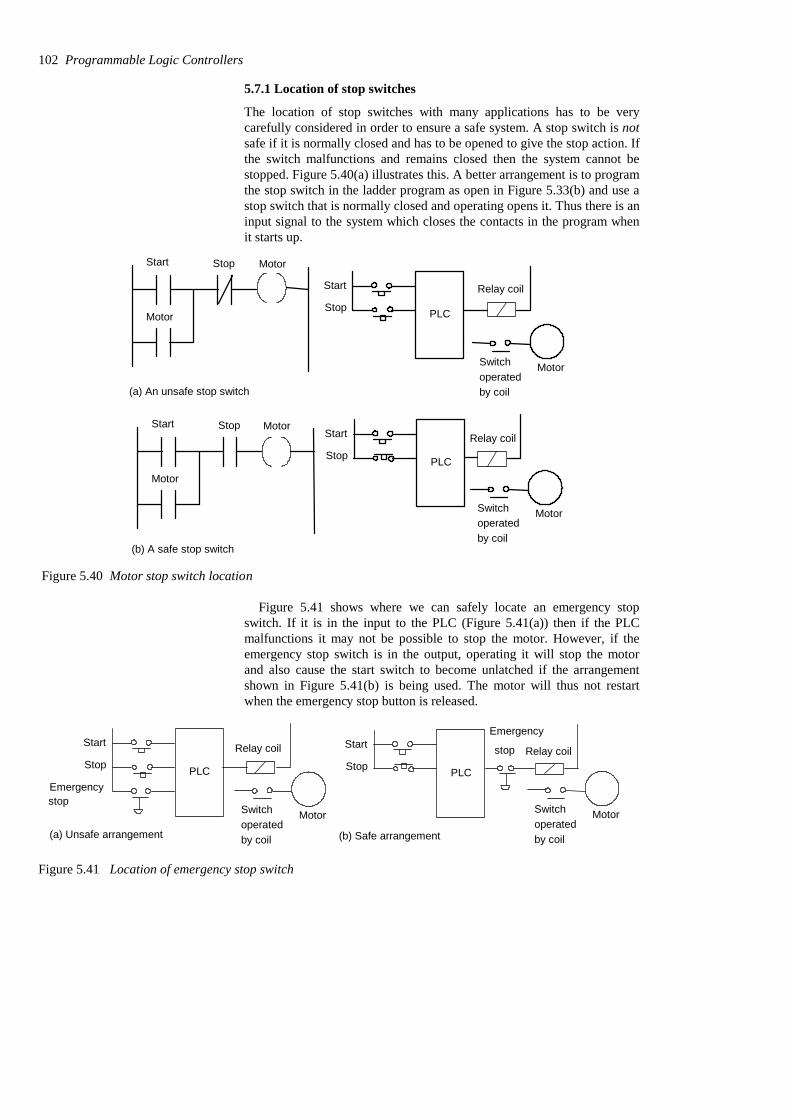
5.7.1 Location of stop switches
The location of stop switches with many applications has to be verycarefully considered in order to ensure a safe system. A stop switch is notsafe if it is normally closed and has to be opened to give the stop action. Ifthe switch malfunctions and remains closed then the system cannot bestopped. Figure 5.40(a) illustrates this. A better arrangement is to programthe stop switch in the ladder program as open in Figure 5.33(b) and use astop switch that is normally closed and operating opens it. Thus there is aninput signal to the system which closes the contacts in the program whenit starts up.
Start Stop
Motor
Motor
(a) An unsafe stop switch
Start Stop
Motor
Motor
(b) A safe stop switch
PLC
Relay coil
MotorSwitchoperatedby coil
Start
Stop
PLC
Relay coil
MotorSwitchoperatedby coil
Start
Stop
Figure 5.40 Motor stop switch location
Figure 5.41 shows where we can safely locate an emergency stopswitch. If it is in the input to the PLC (Figure 5.41(a)) then if the PLCmalfunctions it may not be possible to stop the motor. However, if theemergency stop switch is in the output, operating it will stop the motorand also cause the start switch to become unlatched if the arrangementshown in Figure 5.41(b) is being used. The motor will thus not restartwhen the emergency stop button is released.
PLC
Relay coil
MotorSwitchoperatedby coil
Start
Stop
Emergency
(b) Safe arrangement
stop
PLC
Relay coil
MotorSwitchoperatedby coil
Start
Stop
Emergency
(a) Unsafe arrangement
stop
Figure 5.41 Location of emergency stop switch
102 Programmable Logic Controllers
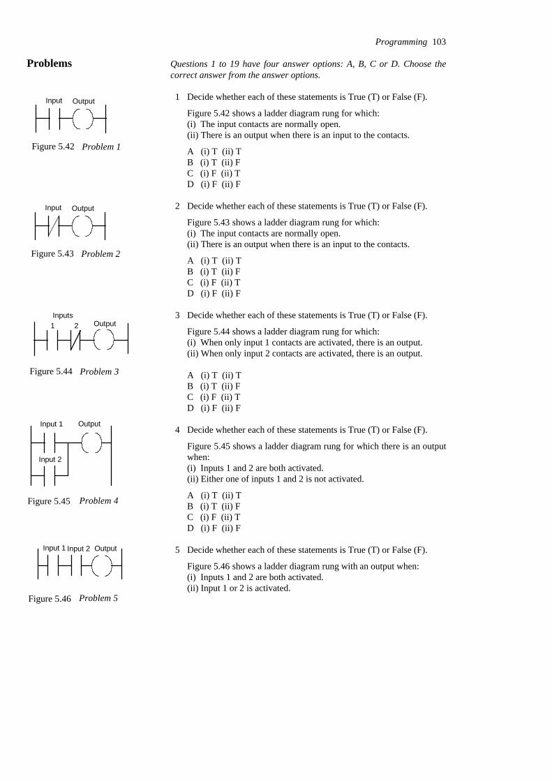
Problems Questions 1 to 19 have four answer options: A, B, C or D. Choose thecorrect answer from the answer options.
1 Decide whether each of these statements is True (T) or False (F).
Figure 5.42 shows a ladder diagram rung for which:(i) The input contacts are normally open.(ii) There is an output when there is an input to the contacts.
A (i) T (ii) TB (i) T (ii) FC (i) F (ii) TD (i) F (ii) F
2 Decide whether each of these statements is True (T) or False (F).
Figure 5.43 shows a ladder diagram rung for which:(i) The input contacts are normally open.(ii) There is an output when there is an input to the contacts.
A (i) T (ii) TB (i) T (ii) FC (i) F (ii) TD (i) F (ii) F
3 Decide whether each of these statements is True (T) or False (F).
Figure 5.44 shows a ladder diagram rung for which:(i) When only input 1 contacts are activated, there is an output.(ii) When only input 2 contacts are activated, there is an output.
A (i) T (ii) TB (i) T (ii) FC (i) F (ii) TD (i) F (ii) F
4 Decide whether each of these statements is True (T) or False (F).
Figure 5.45 shows a ladder diagram rung for which there is an outputwhen:(i) Inputs 1 and 2 are both activated.(ii) Either one of inputs 1 and 2 is not activated.
A (i) T (ii) TB (i) T (ii) FC (i) F (ii) TD (i) F (ii) F
5 Decide whether each of these statements is True (T) or False (F).
Figure 5.46 shows a ladder diagram rung with an output when:(i) Inputs 1 and 2 are both activated.(ii) Input 1 or 2 is activated.
Programming 103
Figure 5.42 Problem 1
Input Output
Figure 5.43 Problem 2
Input Output
1 2Inputs
Figure 5.44 Problem 3
Output
Input 1
Input 2
Figure 5.45 Problem 4
Output
Figure 5.46 Problem 5
Input 1 Input 2 Output

A (i) T (ii) TB (i) T (ii) FC (i) F (ii) TD (i) F (ii) F
6 Decide whether each of these statements is True (T) or False (F).
Figure 5.47 shows a ladder diagram rung for which there is an outputwhen:(i) Input 1 is momentarily activated before reverting to its normallyopen state.(ii) Input 2 is activated.
A (i) T (ii) TB (i) T (ii) FC (i) F (ii) TD (i) F (ii) F
Questions 7 to 10 refer to the following logic gate systems:
A ANDB ORC NORD NAND
7 Which form of logic gate system is given by a ladder diagram with arung having two normally open sets of contacts in parallel?
8 Which form of logic gate system is given by a ladder diagram with arung having two normally closed gates in parallel?
9 Which form of logic gate system is given by a ladder diagram with arung having two normally closed gates in series?
10 Which form of logic gate system is given by a ladder diagram with arung having two normally open gates in series?
Problems 11 to 14 concern Boolean expressions for inputs A and B.
A Input A is in series with input B, both inputs being normally off.B Input A is in parallel with input B, both inputs being normally
off.C Input A, normally off, is in series with input B which is normally
on.D Input A is in parallel with input B, both inputs being normally
on.
11 Which arrangement of inputs is described by the Boolean relationshipA$B?
12 Which arrangement of inputs is described by the Boolean relationshipA + B?
104 Programmable Logic Controllers
Input 1 Input 2 Output
Output
Figure 5.47 Problem 6

13 Which arrangement of inputs is described by the Boolean relationshipA + B?
14 Which arrangement of inputs is described by the Boolean relationshipA$B?
15 The arrangement of inputs in Figure 5.48 is described by the Booleanexpression:
A A$B$CB (A + C)$BC (A + B)$CD A$C + B
16 Decide whether each of these statements is True (T) or False (F).
For the function block diagram in Figure 5.49, there is an output:(i) When A is 1.(ii) When B is 1.
A (i) T (ii) TB (i) T (ii) FC (i) F (ii) TD (i) F (ii) F
17 Decide whether each of these statements is True (T) or False (F).
For the function block diagram in Figure 5.50, there is an output:(i) When A is 1.(ii) When B is 1.
A (i) T (ii) TB (i) T (ii) FC (i) F (ii) TD (i) F (ii) F
18 Decide whether each of these statements is True (T) or False (F).
A
B
C>1
& Output
Figure 5.51 Problem 18
For the functional block diagram in Figure 5.51, there is an output:(i) When A is 1, B is 0 and C is 0.(ii) When A is 0, B is 1 and C is 1.
A (i) T (ii) TB (i) T (ii) FC (i) F (ii) TD (i) F (ii) F
Programming 105
A B
C
Figure 5.48 Problem 15
>1A
B
Figure 5.49 Problem 16
>1A
B
Figure 5.50 Problem 17
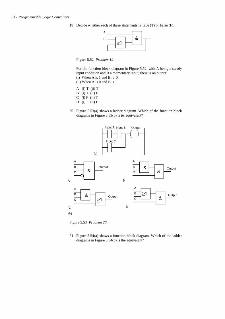
19 Decide whether each of these statements is True (T) or False (F).
A
B>1
&
Figure 5.52 Problem 19
For the function block diagram in Figure 5.52, with A being a steadyinput condition and B a momentary input, there is an output:(i) When A is 1 and B is 0.(ii) When A is 0 and B is 1.
A (i) T (ii) TB (i) T (ii) FC (i) F (ii) TD (i) F (ii) F
20 Figure 5.53(a) shows a ladder diagram. Which of the function blockdiagrams in Figure 5.53(b) is its equivalent?
(b)
Input A Input B
Input C
(a)
Output
A
B
C &
A
A
B
C&
&
B
Output Output
A
B
C&
>1C D
A
B
C &>1 OutputOutput
Figure 5.53 Problem 20
21 Figure 5.54(a) shows a function block diagram. Which of the ladderdiagrams in Figure 5.54(b) is the equivalent?
106 Programmable Logic Controllers
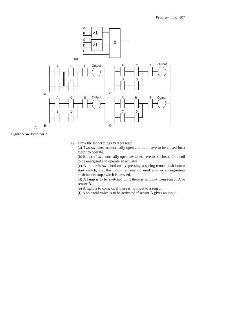
A
B
C
D
E
>1
>1 &
(a)
A
B
C
D
E
AA
B
C
D
E
B
A
B
C
D
E
CA
C D
E
D
B
(b)
Output Output
Output Output
Figure 5.54 Problem 21
22 Draw the ladder rungs to represent:(a) Two switches are normally open and both have to be closed for amotor to operate.(b) Either of two, normally open, switches have to be closed for a coilto be energised and operate an actuator.(c) A motor is switched on by pressing a spring-return push buttonstart switch, and the motor remains on until another spring-returnpush button stop switch is pressed.(d) A lamp is to be switched on if there is an input from sensor A orsensor B.(e) A light is to come on if there is no input to a sensor.(f) A solenoid valve is to be activated if sensor A gives an input.
Programming 107
6 IL, SFC and ST programming methods
This chapter continues from the previous chapter and discusses the otherIEC 1131-3 (International Electrotechnical Commission) programminglanguages, i.e. instruction lists (IL), sequential function charts (SFC), andstructured text (ST).
6.1 Instruction lists A programming method, which can be considered to be the entering of aladder program using text, is instruction lists (IL). Instruction list givesprograms which consist of a series of instructions, each instruction beingon a new line. An instruction consists of an operator followed by one ofmore operands, i.e. the subjects of the operator. In terms of ladderdiagrams an operator may be regarded as a ladder element. Eachinstruction may either use or change the value stored in a memoryregister. For this, mnemonic codes are used, each code corresponding toan operator/ladder element. The codes used differ to some extent frommanufacturer to manufacturer, though a standard IEC 1131-3 has beenproposed and is being widely adopted. Table 6.1 shows some of the codesused by manufacturers, and the proposed standard, for instructions used inthis chapter (see later chapters for codes for other functions).
Table 6.1 Instruction code mnemonics
An outputStore result registerinto operand
=OUTOUTST
A parallel element withclosed contacts
Boolean OR withnegative operand
ONOR NOTORIORN
A parallel element with opencontacts
Boolean OROOROROR
A series element with closedcontacts
Boolean AND withnegative operand
ANAND NOTANIANDN
A series element with opencontacts
Boolean ANDAANDANDAND
Start a rung with closedcontacts
Load negative operandinto result register
ANLD NOTLDILDN
Start a rung with opencontacts
Load operand intoresult register
ALDLDLD
Ladder diagramOperationSiemens/Telemecanique
OMRONMitsubishiIEC 1131-3Operators
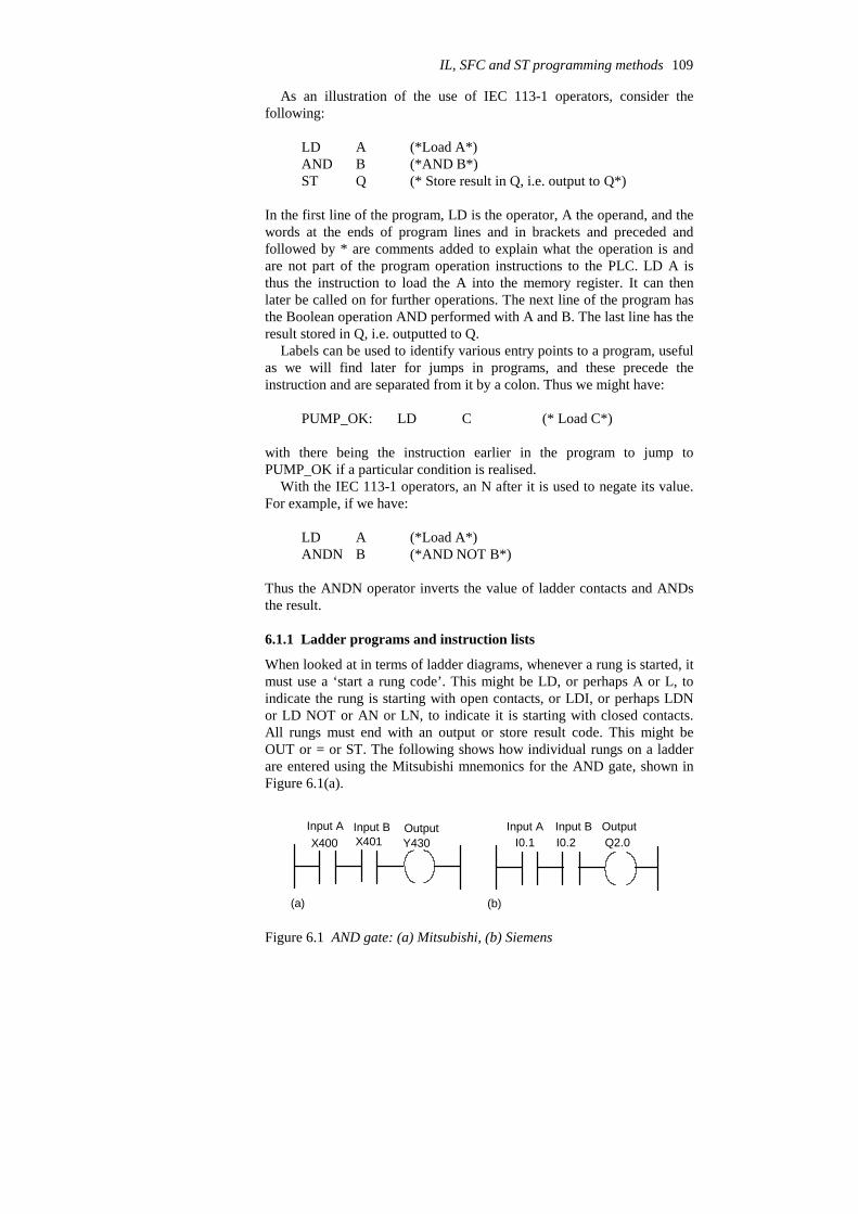
As an illustration of the use of IEC 113-1 operators, consider thefollowing:
(* Store result in Q, i.e. output to Q*)QST(*AND B*)BAND(*Load A*)ALD
In the first line of the program, LD is the operator, A the operand, and thewords at the ends of program lines and in brackets and preceded andfollowed by * are comments added to explain what the operation is andare not part of the program operation instructions to the PLC. LD A isthus the instruction to load the A into the memory register. It can thenlater be called on for further operations. The next line of the program hasthe Boolean operation AND performed with A and B. The last line has theresult stored in Q, i.e. outputted to Q.
Labels can be used to identify various entry points to a program, usefulas we will find later for jumps in programs, and these precede theinstruction and are separated from it by a colon. Thus we might have:
(* Load C*)CLDPUMP_OK:
with there being the instruction earlier in the program to jump toPUMP_OK if a particular condition is realised.
With the IEC 113-1 operators, an N after it is used to negate its value.For example, if we have:
(*AND NOT B*)BANDN(*Load A*)ALD
Thus the ANDN operator inverts the value of ladder contacts and ANDsthe result.
6.1.1 Ladder programs and instruction lists
When looked at in terms of ladder diagrams, whenever a rung is started, itmust use a ‘start a rung code’. This might be LD, or perhaps A or L, toindicate the rung is starting with open contacts, or LDI, or perhaps LDNor LD NOT or AN or LN, to indicate it is starting with closed contacts.All rungs must end with an output or store result code. This might beOUT or = or ST. The following shows how individual rungs on a ladderare entered using the Mitsubishi mnemonics for the AND gate, shown inFigure 6.1(a).
X400 X401 Y430Input A Input B Output
(a) (b)
I0.1 I0.2 Q2.0Input A Input B Output
Figure 6.1 AND gate: (a) Mitsubishi, (b) Siemens
IL, SFC and ST programming methods 109
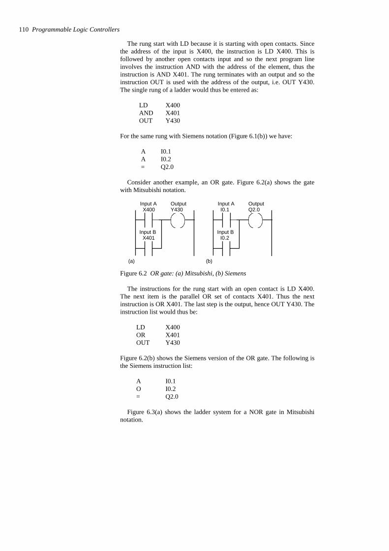
The rung start with LD because it is starting with open contacts. Sincethe address of the input is X400, the instruction is LD X400. This isfollowed by another open contacts input and so the next program lineinvolves the instruction AND with the address of the element, thus theinstruction is AND X401. The rung terminates with an output and so theinstruction OUT is used with the address of the output, i.e. OUT Y430.The single rung of a ladder would thus be entered as:
Y430 OUTX401 ANDX400 LD
For the same rung with Siemens notation (Figure 6.1(b)) we have:
Q2.0 = I0.2 A I0.1 A
Consider another example, an OR gate. Figure 6.2(a) shows the gatewith Mitsubishi notation.
X400
X401
Y430Input A Output
Input B
(a)
I0.1
I0.2
Q2.0Input A Output
Input B
(b)
Figure 6.2 OR gate: (a) Mitsubishi, (b) Siemens
The instructions for the rung start with an open contact is LD X400.The next item is the parallel OR set of contacts X401. Thus the nextinstruction is OR X401. The last step is the output, hence OUT Y430. Theinstruction list would thus be:
Y430 OUT X401 OR X400 LD
Figure 6.2(b) shows the Siemens version of the OR gate. The following isthe Siemens instruction list:
Q2.0= I0.2 O I0.1 A
Figure 6.3(a) shows the ladder system for a NOR gate in Mitsubishinotation.
110 Programmable Logic Controllers
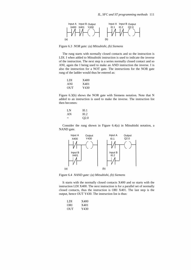
X400 X401 Y430Input A Input B Output
(a)
I0.1 I0.2 Q2.0Input A Input B Output
(b)
Figure 6.3 NOR gate: (a) Mitsubishi, (b) Siemens
The rung starts with normally closed contacts and so the instruction isLDI. I when added to Mitsubishi instruction is used to indicate the inverseof the instruction. The next step is a series normally closed contact and soANI, again the I being used to make an AND instruction the inverse. I isalso the instruction for a NOT gate. The instructions for the NOR gaterung of the ladder would thus be entered as:
Y430 OUT X401 ANI X400 LDI
Figure 6.3(b) shows the NOR gate with Siemens notation. Note that Nadded to an instruction is used to make the inverse. The instruction listthen becomes:
Q2.0 = I0.2 AN I0.1 LN
Consider the rung shown in Figure 6.4(a) in Mitsubishi notation, aNAND gate.
X400 Y430
X401
Input A Output
Input B
(a)
I0.1 Q2.0
I0.2
Input A Output
Input B
(b)
Figure 6.4 NAND gate: (a) Mitsubishi, (b) Siemens
It starts with the normally closed contacts X400 and so starts with theinstruction LDI X400. The next instruction is for a parallel set of normallyclosed contacts, thus the instruction is ORI X401. The last step is theoutput, hence OUT Y430. The instruction list is thus:
Y430 OUT X401 ORI X400 LDI
IL, SFC and ST programming methods 111

Figure 6.4(b) shows the NAND gate in Siemens notation. The instructionlist is then:
Q2.0 = I0.2 ON I0.1 AN
6.1.2 Branch codes
The Exclusive OR (XOR) gate shown in Figure 6.5(a) in Mitsubishinotation has two parallel arms with an AND situation in each arm.
X400 X401
X400 X401
Y430Input A Input B Output
Input A Input B
(a)
I0.0 I0.1
I0.0 I0.1
Q2.0Input A Input B Output
Input A Input B
(b)
Figure 6.5 XOR gate: (a) Mitsubishi, (b) Siemens
In such a situation Mitsubishi uses an ORB instruction to indicate ‘ORtogether parallel branches’. The first instruction is for a normally openpair of contacts X400. The next instruction is for a series set of normallyclosed contacts X401, hence ANI X401. After reading the first twoinstructions, the third instruction starts a new line. It is recognised as anew line because it starts with LDI, all new lines starting with LD or LDI.But the first line has not been ended by an output. The PLC thusrecognises that a parallel line is involved for the second line and readstogether the listed elements until the ORB instruction is reached. Themnemonic ORB (OR branches/blocks together) indicates to the PLC thatit should OR the results of the first and second instructions with that of thenew branch with the third and fourth instructions. The list concludes withthe output OUT Y430. The instruction list would thus be entered as:
Y430 OUT ORB
X401AND X400LDI X401 ANI X400 LD
Figure 6.5(b) shows the Siemens version of XOR gate. Brackets areused to indicate that certain instructions are to be carried out as a block.They are used in the same way as brackets in any mathematical equation.For example, (2 + 3)/4 means that the 2 and 3 must be added beforedividing by 4. Thus with the Siemens instruction list we have in step 0 theinstruction A(. The brackets close in step 3. This means that the A in step0 is applied only after the instructions in steps 1 and 2 have been applied.
112 Programmable Logic Controllers
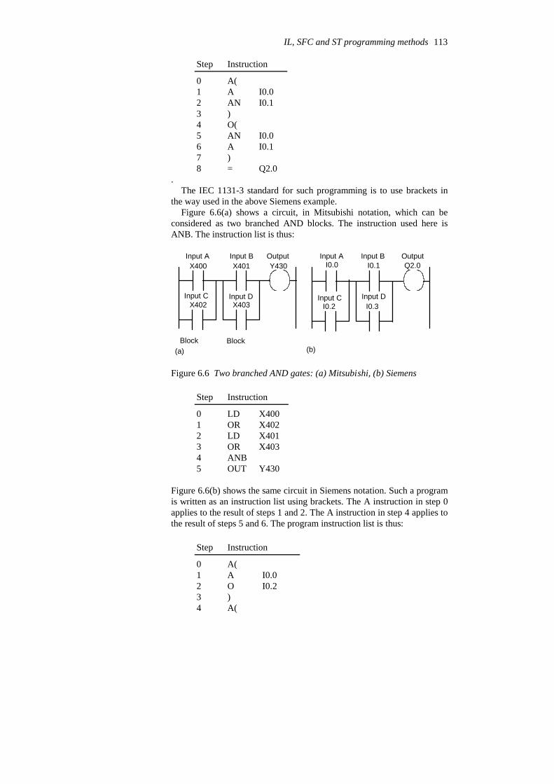
Q2.0=8)7
I0.1 A6 I0.0AN5
O(4 )3
I0.1 AN 2 I0.0A1 A(0
InstructionStep
.The IEC 1131-3 standard for such programming is to use brackets in
the way used in the above Siemens example.Figure 6.6(a) shows a circuit, in Mitsubishi notation, which can be
considered as two branched AND blocks. The instruction used here isANB. The instruction list is thus:
X400 X401
X402 X403
Y430
Block Block
I0.0 I0.1
I0.2 I0.3
Q2.0
(a) (b)
Input A Input B Output Input A Input B Output
Input C Input D Input C Input D
Figure 6.6 Two branched AND gates: (a) Mitsubishi, (b) Siemens
Y430 OUT 5 ANB4
X403OR3 X401LD2 X402 OR1 X400 LD0
InstructionStep
Figure 6.6(b) shows the same circuit in Siemens notation. Such a programis written as an instruction list using brackets. The A instruction in step 0applies to the result of steps 1 and 2. The A instruction in step 4 applies tothe result of steps 5 and 6. The program instruction list is thus:
A(4 )3
I0.2O2 I0.0 A1 A(0
InstructionStep
IL, SFC and ST programming methods 113

Q2.0=8)7
I0.3O6I0.1A5
6.1.3 More than one rung
Figure 6.7(a) shows a ladder, in Mitsubishi notation, with two rungs. Inwriting the instruction list we just write the instructions for each line inturn. The instruction LD or LDI indicates to the PLC that a new rung isstarting. The instruction list is thus:
X400 Y430
X400 Y431
(a)
Input A Output A
Input A Output B
I0.0 Q2.0
I0.0 Q2.1
(b)
Input A Output A
Input A Output B
Figure 6.7 Toggle circuit: (a) Mitsubishi, (b) Siemens
Y431OUT X400LDI Y430OUTX400 LD
The system is one where when X400 is not activated, there is an outputfrom Y431 but not Y430. When X400 is activated, there is then an outputfrom Y430 but not Y431.
Figure 6.7(b) shows the same program in Siemens notation. The =instruction indicates the end of a line. The A or AN instruction does notnecessarily indicate the beginning of a rung since the same instruction isused for AND and AND NOT. The instruction list is then:
Q2.1= I0.0AN Q2.0=I0.0 A
6.1.4 Programming examples
The following tasks are intended to illustrate the application of theprogramming techniques given in this section and are the examples forwhich ladder diagrams and function block diagrams were derived inSection 5.7. See that section for an explanation of the ladder diagrams;here we just show the instruction lists relating to the programs.
A signal lamp is required to be switched on if a pump is running andthe pressure is satisfactory, or if the lamp test switch is closed. Figure 6.8shows the ladder program and the related instruction list.
114 Programmable Logic Controllers

Pump PressureX400 X401
Lamp
Y430
X402
TestEND
LDANDLDORBOUT
X400X401X402
Y430END
Figure 6.8 Signal lamp task
For a valve which is to be operated to lift a load when a pump isrunning and either the lift switch is operated or a switch operatedindicating that the load has not already been lifted and is at the bottom ofits lift channel, Figure 6.9 shows the ladder program and the relatedinstruction list.
END
Lift
Not lifted
ValvePumpX400 X401 Y430
X402
LDORANDOUTEND
X400X402X401Y430
Figure 6.9 Valve operation program
For a system where there has to be no output when any one of foursensors gives an output, otherwise there is to be an output, Figure 6.10shows the ladder program and the instruction list.
1 2 3 4Sensors
OutputX400 X401 X402 X403 Y430 LDI
ANIANIANIOUT
X400X401X402X403Y430
ENDEND
Figure 6.10 Output switched off by any one of four sensors beingactivated
6.2 Sequential function If we wanted to describe a traffic lamp sequence, one way we could dothis would be to represent it as a sequence of functions or states such asred light state and green light state and the inputs and outputs to each
IL, SFC and ST programming methods 115
charts

state. Figure 6.11 illustrates this. State 0 has an input which is triggeredafter the green light has been on for 1 minute and an output of red lighton. State 1 has an input which is triggered after the red light has been onfor 1 minute and an output of green light on.
0
1
Red lightonly on
Green lightonly on
States Outputs
red light on for 1 minute
green light on for 1 minuteTransfer condition to next state is
Transfer condition for next state is
Figure 6.11 Sequence for traffic lights
The term sequential function chart (SFC) is used for a pictorialrepresentation of a system’s operation to show the sequence of the eventsinvolved in its operation. SFC charts have the following elements:
1 The operation is described by a number of separate sequentiallyconnected states or steps which are represented by rectangular boxes,each representing a particular state of the system being controlled.The initial step in a program is represented differently to the othersteps, Figure 6.12 shows its representation.
State/step
Transition condition
Start Initial step in which the system
Stop Final step
etc.
Transition condition
Output
is held ready to start
Figure 6.12 A state and its transition
2 Each connecting line between states has a horizontal bar representingthe transition condition that has to be realised before the system canmove from one state to the next. Two steps can never be directly
116 Programmable Logic Controllers

connected, they must always be separated by a transition. Twotransitions can never directly follow from one to another, they mustalways be separated by a step.
3 When the transfer conditions to the next state are realised then thenext state or step in the program occurs.
4 The process thus continues from one state to the next until thecomplete machine cycle is completed.
5 Outputs/actions at any state are represented by horizontally linkedboxes and occur when that state has been realised.
As an illustration, Figure 6.13 shows part of an SFC and its equivalentladder diagram.
OUT 1Step 0
IN 1
IN 2
IN 1 OUT 1 Step 0
Step 1 OUT 2
IN 3
Step 1
When IN 1 occurs, thenstep 0 is realised andOUT 1 occurs
When step 1 has beenrealised, i.e. OUT 1, andthe transfer condition IN 2, then step 1 isrealised and OUT 2occurs
OUT 1 IN 2 OUT 3
Start
EndEND
Figure 6.13 SFC and equivalent ladder diagram
As an illustration of the principles of SFC, consider the situation with,say, part of the washing cycle of a domestic washing machine where thedrum is to be filled with water and then when full a heater has to beswitched on and remain on until the temperature reaches the requiredlevel. Then the drum is to be rotated for a specified time. We have asequence of states which can be represented in the manner shown inFigure 6.14.
6.2.1 Branching and convergence
Selective branching is illustrated in Figure 6.15 and allows for differentstates to be realised depending on the transfer condition that occurs.
Parallel branching (Figure 6.16), represented by a pair of horizontallines, allows for two or more different states to be realised and proceedsimultaneously.
Figures 6.17 and 6.18 show how convergence is represented by anSFC. In Figure 6.17 the sequence can go from state 2 to state 4 if IN 4occurs or from state 3 to state 4 if IN 5 occurs. In Figure 6.18 thesequence can go simultaneously from both state 2 and state 3 to state 4 ifIN 4 occurs.
IL, SFC and ST programming methods 117
Step 1
Step 2
Fill withwater
Level full switch
Heatwater
Right temperature switch
Step 3 Rotate
Time switch
Start
Start switch pressed
And so on for rest of cycle
Drum
Water
Hot water
Figure 6.14 Washing machine
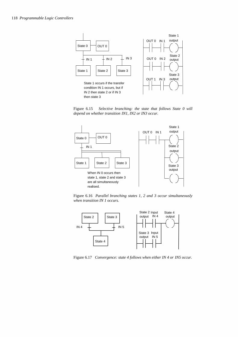
State 0
State 1 State 2 State 3
IN 1 IN 2 IN 3
State 1 occurs if the transfercondition IN 1 occurs, but ifIN 2 then state 2 or if IN 3then state 3
OUT 0OUT 0
OUT 0
OUT 1
IN 1
IN 2
IN 3
State 1output
State 2output
State 3output
Figure 6.15 Selective branching: the state that follows State 0 willdepend on whether transition IN1, IN2 or IN3 occur.
State 0
State 1 State 2 State 3
IN 1
When IN 0 occurs thenstate 1, state 2 and state 3are all simultaneouslyrealised.
OUT 0OUT 0 IN 1
State 1output
State 2output
State 3output
Figure 6.16 Parallel branching states 1, 2 and 3 occur simultaneouslywhen transition IN 1 occurs.
State 2
State 4
State 3
IN 4 IN 5
IN 4State 4output
State 2output
State 3output IN 5
Input
Input
Figure 6.17 Convergence: state 4 follows when either IN 4 or IN5 occur.
118 Programmable Logic Controllers
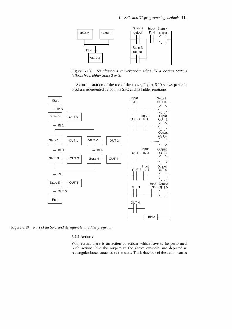
State 2
State 4
State 3
IN 4
IN 4State 4output
State 2output
State 3output
Input
Figure 6.18 Simultaneous convergence: when IN 4 occurs State 4follows from either State 2 or 3.
As an illustration of the use of the above, Figure 6.19 shows part of aprogram represented by both its SFC and its ladder programs.
State 0 OUT 0
State 1 OUT 1 State 2 OUT 2
State 3 OUT 3 State 4 OUT 4
State 5 OUT 5
IN 1
IN 3 IN 4
IN 5
IN 0
IN 0 OUT 0
OUT 0 IN 1 OUT 1
OUT 2
OUT 1 IN 3 OUT 3
OUT 2 IN 4 OUT 4
OUT 3
OUT 4
IN5 OUT 5
Input Output
Input
Input
Input Output
OutputInput
Output
Output
Output
END
Start
End
OUT 5
Figure 6.19 Part of an SFC and its equivalent ladder program
6.2.2 Actions
With states, there is an action or actions which have to be performed.Such actions, like the outputs in the above example, are depicted asrectangular boxes attached to the state. The behaviour of the action can be
IL, SFC and ST programming methods 119
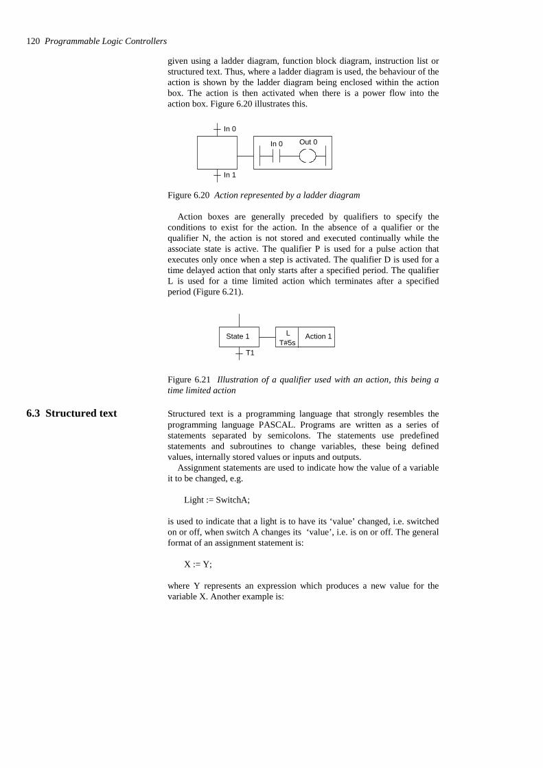
given using a ladder diagram, function block diagram, instruction list orstructured text. Thus, where a ladder diagram is used, the behaviour of theaction is shown by the ladder diagram being enclosed within the actionbox. The action is then activated when there is a power flow into theaction box. Figure 6.20 illustrates this.
In 0 Out 0
In 0
In 1
Figure 6.20 Action represented by a ladder diagram
Action boxes are generally preceded by qualifiers to specify theconditions to exist for the action. In the absence of a qualifier or thequalifier N, the action is not stored and executed continually while theassociate state is active. The qualifier P is used for a pulse action thatexecutes only once when a step is activated. The qualifier D is used for atime delayed action that only starts after a specified period. The qualifierL is used for a time limited action which terminates after a specifiedperiod (Figure 6.21).
Action 1LT#5s
State 1
T1
Figure 6.21 Illustration of a qualifier used with an action, this being atime limited action
6.3 Structured text Structured text is a programming language that strongly resembles theprogramming language PASCAL. Programs are written as a series ofstatements separated by semicolons. The statements use predefinedstatements and subroutines to change variables, these being definedvalues, internally stored values or inputs and outputs.
Assignment statements are used to indicate how the value of a variableit to be changed, e.g.
Light := SwitchA;
is used to indicate that a light is to have its ‘value’ changed, i.e. switchedon or off, when switch A changes its ‘value’, i.e. is on or off. The generalformat of an assignment statement is:
X := Y;
where Y represents an expression which produces a new value for thevariable X. Another example is:
120 Programmable Logic Controllers
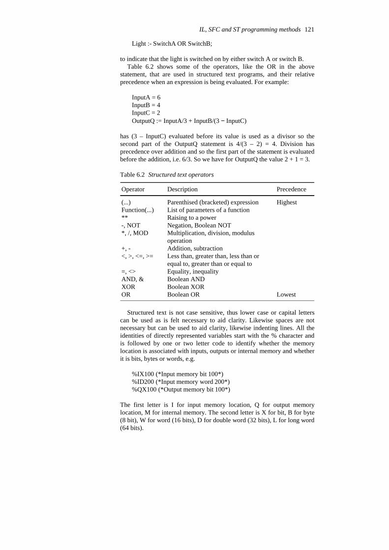
Light :- SwitchA OR SwitchB;
to indicate that the light is switched on by either switch A or switch B. Table 6.2 shows some of the operators, like the OR in the above
statement, that are used in structured text programs, and their relativeprecedence when an expression is being evaluated. For example:
InputA = 6InputB = 4InputC = 2OutputQ := InputA/3 + InputB/(3 − InputC)
has (3 – InputC) evaluated before its value is used as a divisor so thesecond part of the OutputQ statement is 4/(3 – 2) = 4. Division hasprecedence over addition and so the first part of the statement is evaluatedbefore the addition, i.e. 6/3. So we have for OutputQ the value 2 + 1 = 3.
Table 6.2 Structured text operators
LowestBoolean ORORBoolean XORXORBoolean ANDAND, &Equality, inequality=, <>
Less than, greater than, less than orequal to, greater than or equal to
<, >, <=, >=Addition, subtraction+, -
Multiplication, division, modulusoperation
*, /, MODNegation, Boolean NOT-, NOTRaising to a power**List of parameters of a functionFunction(...)
HighestParenthised (bracketed) expression(...)
PrecedenceDescriptionOperator
Structured text is not case sensitive, thus lower case or capital letterscan be used as is felt necessary to aid clarity. Likewise spaces are notnecessary but can be used to aid clarity, likewise indenting lines. All theidentities of directly represented variables start with the % character andis followed by one or two letter code to identify whether the memorylocation is associated with inputs, outputs or internal memory and whetherit is bits, bytes or words, e.g.
%IX100 (*Input memory bit 100*)%ID200 (*Input memory word 200*)%QX100 (*Output memory bit 100*)
The first letter is I for input memory location, Q for output memorylocation, M for internal memory. The second letter is X for bit, B for byte(8 bit), W for word (16 bits), D for double word (32 bits), L for long word(64 bits).
IL, SFC and ST programming methods 121
AT is used to fix the memory location for a variable. Thus we mighthave:
Input1 AT %IX100; (*Input1 is located at input memory bit 100*)
6.3.1 Conditional statements
IF ... THEN ... ELSE is used when selected statements are to be executedwhen certain conditions occur. For example:
IF (Limit_switch1 AND Workpiece_Present) THENGate1 :- Open;Gate2 :- Close;ELSEGate1 :- Close;Gate2 :- Open;End_IF;
Note that the end of the IF statement has to be indicated. Anotherexample, using PLC addresses, is:
IF (I:000/00 = 1) THENO:001/00 :- 1;ELSEO:000/01 = 0;End_IF;
So if there is an input to I:000/00 to make it 1 then output O:001/00 is 1,otherwise it 0.
CASE is used to give the condition that selected statements are to beexecuted if a particular integer value occurs else some other selectedstatements. For example, for temperature control we might have:
CASE (Temperature) OF 0 ... 40 ;Furnace_switch :- On;40 ... 100Furnace_switch :- Off;ELSEFurnace_switch :- Off;End_CASE;
Note, as with all conditional statements, the end of the CASE statementhas to be indicated.
6.3.2 Iteration statements
These are used where it is necessary to repeat one or more statements anumber of times, depending on the state of some variable. The FOR ...DO iteration statement allows a set of statements to be repeateddepending on the value of the iteration integer variable. For example:
FOR Input :- 10 to 0 BY -1
122 Programmable Logic Controllers

DOOutput :- Input;End_FOR;
has the output decreasing by 1 each time the input, dropping from 10 to 0,decreases by 1.
WHILE ... DO allows one or more statements to be executed while aparticular Boolean expression remains true, e.g.:
OutputQ :- 0;WHILE InputA AND InputBDOOutputQ =: OutputQ + 1;End_WHILE;
REPEAT ... UNTIL allows one or more statements to be executed andrepeated whilst a particular Boolean expression remains true.
OutputQ :- 0REPEATOutputQ = OutputQ + 1;UNTIL (Input1 = Off) OR (OutputQ > 5)End_REPEAT;
6.3.3 Structured text programs
Programs have first to define the data types required to represent data e.g.
TYPE Motor: ( Stopped, Running);End_TYPE;
TYPE Valve: (Open, shut);End_TYPE;
TYPE Pressure: REAL; (*The pressure is an analogue value*)End_TYPE;
the variables, i.e. signals from sensors and output signals to be used in aprogram, e.g.
VAR_IN (*Inputs*)PumpFault : BOOL; (*Pump operating fault is a Boolean variable*)End_VAR;
VAR_OUT (*Outputs*)Motor_speed : REAL;End_VAR;
VAR_INValue: INT; (*The value is an integer*)End_VAR;
IL, SFC and ST programming methods 123
VARInput1 AT %IX100; (*Input1 is located at input memory bit 100*)End_VAR;
and any initial values to be given to variables, e.g.
VARTemp : REAL :-100; (*Initial value is a an analogue number 100*)End_VAR;
before getting down to the instruction statements.
Problems Questions 1 to 21 have four answer options: A, B, C or D. Choose thecorrect answer from the answer options.
1 Decide whether each of these statements is True (T) or False (F).
The instruction list:
Y430OUTX402ANDX401LD
describes a ladder diagram rung for which there is an output when:(i) Input X401 is activated but X402 is not.(ii) Input X401 and input X402 are both activated.
A (i) T (ii) TB (i) T (ii) FC (i) F (ii) TD (i) F (ii) F
2 Decide whether each of these statements is True (T) or False (F).
The instruction list:
Y430OUTX402ORX401LD
describes a ladder diagram rung for which there is an output when:(i) Input X401 is activated but X402 is not.(ii) Input X402 is activated but X401 is not.
A (i) T (ii) TB (i) T (ii) FC (i) F (ii) TD (i) F (ii) F
3 Decide whether each of these statements is True (T) or False (F).
The instruction list:
X402ANIX401LD
124 Programmable Logic Controllers

Y430OUT
describes a ladder diagram rung for which there is an output when:(i) Input X401 is activated but X402 is not.(ii) Input X401 and input X402 are both activated.
A (i) T (ii) TB (i) T (ii) FC (i) F (ii) TD (i) F (ii) F
4 Decide whether each of these statements is True (T) or False (F).
The instruction list:
Y430OUTX402ANIX401LDI
describes a ladder diagram rung for which there is an output when:(i) Input X401 is activated but X402 is not.(ii) Input X401 and input X402 are both activated.
A (i) T (ii) TB (i) T (ii) FC (i) F (ii) TD (i) F (ii) F
5 Decide whether each of these statements is True (T) or False (F).
The instruction list:
Y430OUTX402ANIY430ORX401LD
describes a ladder diagram rung for which there is:(i) An output when input X401 is momentarily activated.(ii) No output when X402 is activated.
A (i) T (ii) TB (i) T (ii) FC (i) F (ii) TD (i) F (ii) F
6 Decide whether each of these statements is True (T) or False (F).
The instruction list:
Q2.0=I0.2AI0.1A
describes a ladder diagram rung for which there is an output when:(i) Input I0.1 is activated but I0.2 is not.(ii) Input I0.1 and input I0.2 are both activated.
IL, SFC and ST programming methods 125

A (i) T (ii) TB (i) T (ii) FC (i) F (ii) TD (i) F (ii) F
7 Decide whether each of these statements is True (T) or False (F).
The instruction list:
Q2.0=I0.2OI0.1A
describes a ladder diagram rung for which there is an output when:(i) Input I0.1 is activated but I0.2 is not.(ii) Input I0.2 is activated but I0.1 is not.
A (i) T (ii) TB (i) T (ii) FC (i) F (ii) TD (i) F (ii) F
8 Decide whether each of these statements is True (T) or False (F).
The instruction list:
Q2.0=I0.2ANI0.1A
describes a ladder diagram rung for which there is an output when:(i) Input I0.1 is activated but I0.2 is not.(ii) Input I0.1 and input I0.2 are both activated.
A (i) T (ii) TB (i) T (ii) FC (i) F (ii) TD (i) F (ii) F
9 Decide whether each of these statements is True (T) or False (F).
The instruction list:
Q2.0=I0.2ANI0.1AN
describes a ladder diagram rung for which there is an output when:(i) Input I0.1 is activated but I0.2 is not.(ii) Input I0.1 and input I0.2 are both activated.
A (i) T (ii) TB (i) T (ii) FC (i) F (ii) TD (i) F (ii) F
126 Programmable Logic Controllers

10 Decide whether each of these statements is True (T) or False (F).
The instruction list:
Q2.0=I0.2ANQ2.0OI0.1A
describes a ladder diagram rung for which there is:(i) An output when input I0.1 is momentarily activated.(ii) No output when I0.2 is activated.
A (i) T (ii) TB (i) T (ii) FC (i) F (ii) TD (i) F (ii) F
11 Decide whether each of these statements is True (T) or False (F).
For the sequential function chart shown in Figure 6.22:(i) State 1 is realised when the condition X1 is realised.(ii) Output 1 occurs when the condition X2 is realised.
A (i) T (ii) TB (i) T (ii) FC (i) F (ii) TD (i) F (ii) F
12 Decide whether each of these statements is True (T) or False (F).
State 1
State 2 State 3
X2 X3
Figure 6.23 Problem 12
For the sequential function chart shown in Figure 6.23, if State 1 isactive:(i) State 2 is realised when the condition X2 is realised.(ii) State 3 occurs when the condition X3 is realised.
A (i) T (ii) TB (i) T (ii) FC (i) F (ii) TD (i) F (ii) F
13 For the ladder program described in Figure 6.24(a), which of thesequential function charts in Figure 6.24(b) will represent it?
IL, SFC and ST programming methods 127
X1
X2
Output 1State 1
Figure 6.22 Problem 11
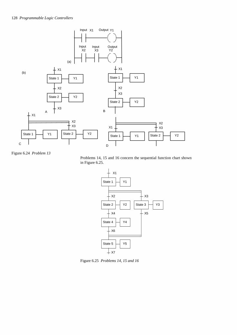
X1
X2
X3
Y1
Y2
State 1
State 2
A
X1
X2
X3
Y1
Y2
State 1
State 2
BX1
X2X3
Y1 Y2State 1 State 2
C
X1X2X3
Y1 Y2State 1 State 2
D
(b)
X1
X2 X3
Y1
Y2
(a)
Input Output
Input Input Output
Figure 6.24 Problem 13Problems 14, 15 and 16 concern the sequential function chart shownin Figure 6.25.
X1
X2 X3
X4 X5
X6
X7
State 1
State 2 State 3
State 4
State 5
Y1
Y2 Y3
Y4
Y5
Figure 6.25 Problems 14, 15 and 16
128 Programmable Logic Controllers
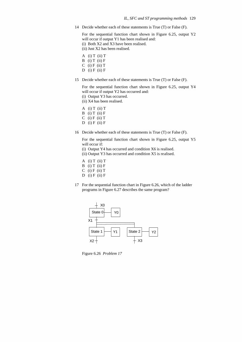
14 Decide whether each of these statements is True (T) or False (F).
For the sequential function chart shown in Figure 6.25, output Y2will occur if output Y1 has been realised and:(i) Both X2 and X3 have been realised.(ii) Just X2 has been realised.
A (i) T (ii) TB (i) T (ii) FC (i) F (ii) TD (i) F (ii) F
15 Decide whether each of these statements is True (T) or False (F).
For the sequential function chart shown in Figure 6.25, output Y4will occur if output Y2 has occurred and:(i) Output Y3 has occurred.(ii) X4 has been realised.
A (i) T (ii) TB (i) T (ii) FC (i) F (ii) TD (i) F (ii) F
16 Decide whether each of these statements is True (T) or False (F).
For the sequential function chart shown in Figure 6.25, output Y5will occur if:(i) Output Y4 has occurred and condition X6 is realised.(ii) Output Y3 has occurred and condition X5 is realised.
A (i) T (ii) TB (i) T (ii) FC (i) F (ii) TD (i) F (ii) F
17 For the sequential function chart in Figure 6.26, which of the ladderprograms in Figure 6.27 describes the same program?
State 0
State 1 State 2
X0
X1
X2 X3
Y0
Y1 Y2
Figure 6.26 Problem 17
IL, SFC and ST programming methods 129
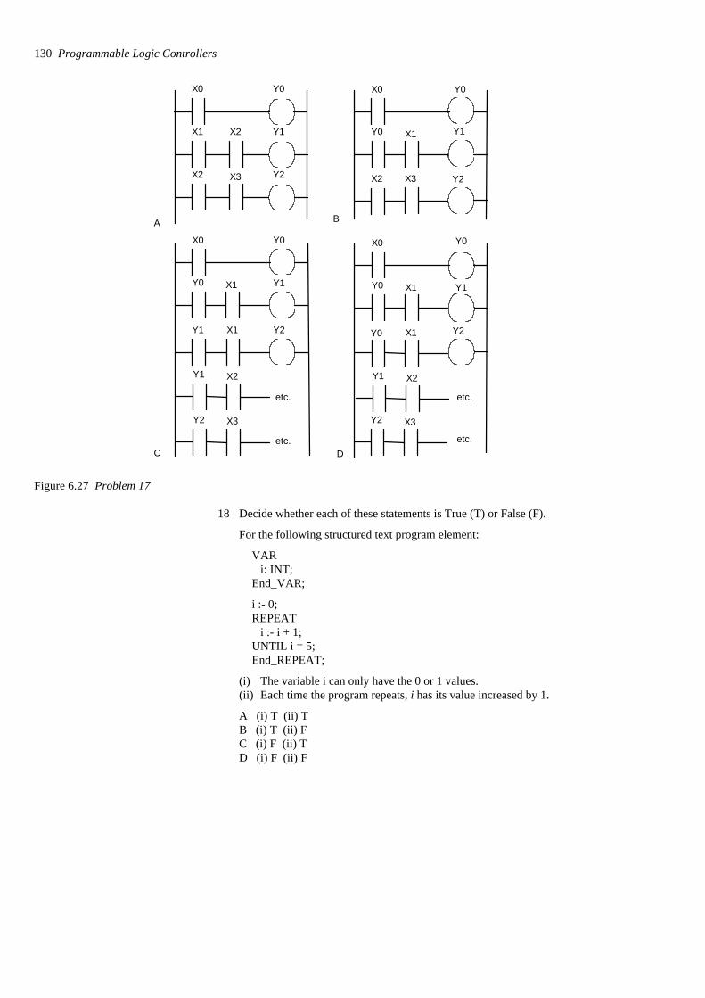
X0 Y0
X1 Y1
X2 Y2X3
A
X0 Y0
X1 Y1
B
Y0
X2 Y2X3
X0 Y0
X1 Y1
C
Y0
Y2
X2Y1
X3Y2
etc.
etc.
X0 Y0
X1 Y1
D
Y0
X1 Y2Y0
X2Y1
X2
X3Y2
etc.
etc.
Y1 X1
Figure 6.27 Problem 17
18 Decide whether each of these statements is True (T) or False (F).
For the following structured text program element:
VARi: INT;
End_VAR;
i :- 0;REPEAT
i :- i + 1;UNTIL i = 5;End_REPEAT;
(i) The variable i can only have the 0 or 1 values.(ii) Each time the program repeats, i has its value increased by 1.
A (i) T (ii) TB (i) T (ii) FC (i) F (ii) TD (i) F (ii) F
130 Programmable Logic Controllers
19 Decide whether each of these statements is True (T) or False (F).
For the following structured text program element:
IF Input1 THENMotor:- 1;End_IF;
IF Input2 THENMotor:- 0;End_IF;
(i) When input 1 occurs then the motor is switched on.(ii) When input 2 occurs then the motor is switched off.
A (i) T (ii) TB (i) T (ii) FC (i) F (ii) TD (i) F (ii) F
20 Decide whether each of these statements is True (T) or False (F).
For the following structured text program element:
IF (Limit_switch_1 AND Workpiece_Present) ThenGate_1 :- Open;Gate_2 :- Closed;ELSEGate_1 :- Closed;Gate_2 :- Open;End_IF;
(i) If only the workpiece is present, gate 1 is open and gate 2 closed.(ii) If only the limit switch is activated, gate 1 is closed and gate 2 is
open.
A (i) T (ii) TB (i) T (ii) FC (i) F (ii) TD (i) F (ii) F
21 Decide whether each of these statements is True (T) or False (F).
For the following structured text program element:
VARStart_Up AT %IX120;End_VARStart_Up:(i) Can be found at input memory location bit 120.(ii) Has the value 120 bits.
A (i) T (ii) TB (i) T (ii) FC (i) F (ii) TD (i) F (ii) F
IL, SFC and ST programming methods 131
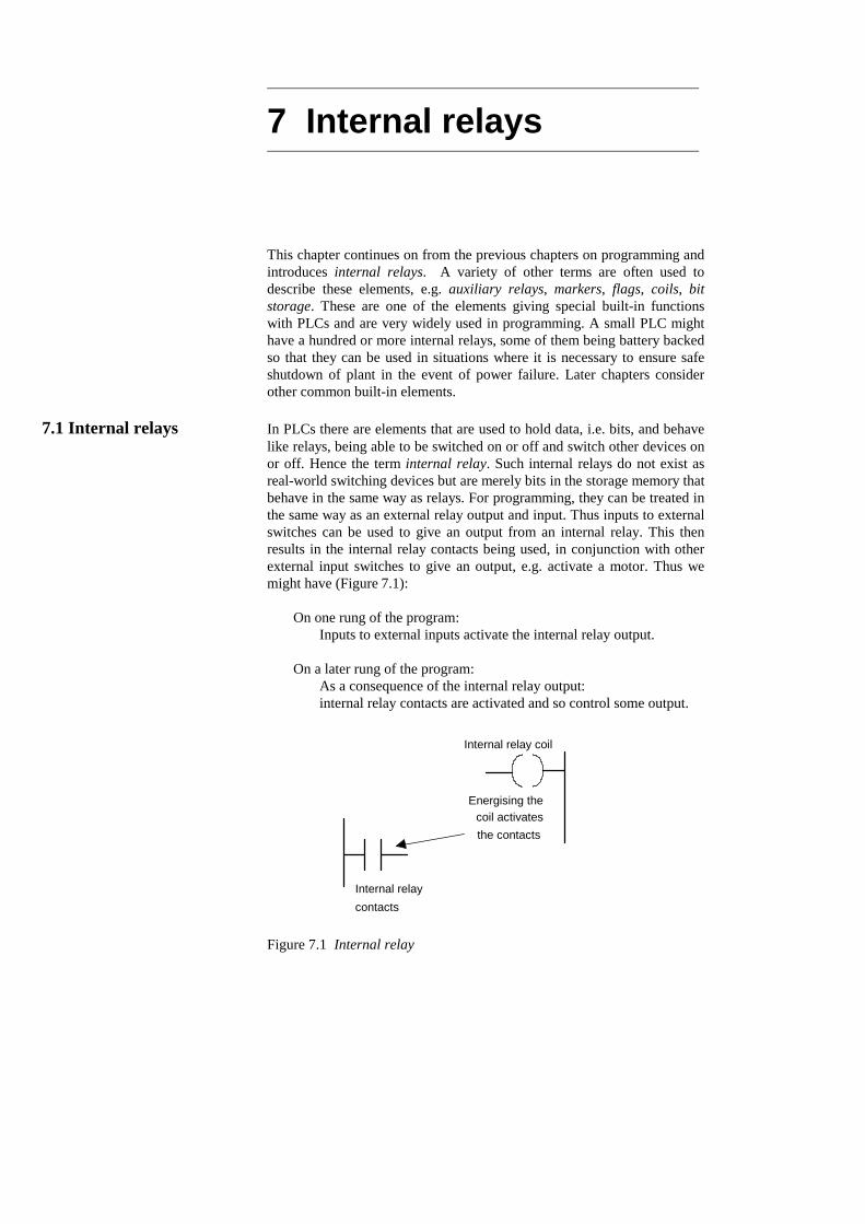
7 Internal relays
This chapter continues on from the previous chapters on programming andintroduces internal relays. A variety of other terms are often used todescribe these elements, e.g. auxiliary relays, markers, flags, coils, bitstorage. These are one of the elements giving special built-in functionswith PLCs and are very widely used in programming. A small PLC mighthave a hundred or more internal relays, some of them being battery backedso that they can be used in situations where it is necessary to ensure safeshutdown of plant in the event of power failure. Later chapters considerother common built-in elements.
7.1 Internal relays In PLCs there are elements that are used to hold data, i.e. bits, and behavelike relays, being able to be switched on or off and switch other devices onor off. Hence the term internal relay. Such internal relays do not exist asreal-world switching devices but are merely bits in the storage memory thatbehave in the same way as relays. For programming, they can be treated inthe same way as an external relay output and input. Thus inputs to externalswitches can be used to give an output from an internal relay. This thenresults in the internal relay contacts being used, in conjunction with otherexternal input switches to give an output, e.g. activate a motor. Thus wemight have (Figure 7.1):
On one rung of the program: Inputs to external inputs activate the internal relay output.
On a later rung of the program: As a consequence of the internal relay output: internal relay contacts are activated and so control some output.
Internal relay coil
Internal relaycontacts
Energising thecoil activatesthe contacts
Figure 7.1 Internal relay

In using an internal relay, it has to be activated on one rung of aprogram and then its output used to operate switching contacts on anotherrung, or rungs, of the program. Internal relays can be programmed with asmany sets of associated contacts as desired.
To distinguish internal relay outputs from external relay outputs, theyare given different types of addresses. Different manufacturers tend to usedifferent terms for internal relays and different ways of expressing theiraddresses. For example, Mitsubishi uses the term auxiliary relay ormarker and the notation M100, M101, etc. Siemens uses the term flag andnotation F0.0, F0.1, etc. Telemecanique uses the term bit and notation B0,B1, etc. Toshiba uses the term internal relay and notation R000, R001,etc. Allen-Bradley uses the term bit storage and notation in the PLC-5 ofthe form B3/001, B3/002, etc.
7.2 Ladder programs With ladder programs, an internal relay output is represented using thesymbol for an output device, namely ( ), with an address which indicatesthat it is an internal relay rather than an external relay. Thus, with aMitsubishi PLC, we might have the address M100, the M indicating that itis an internal relay or marker rather than an external device. The internalrelay switching contacts are designated with the symbol for an inputdevice, namely | |, and given the same address as the internal relay output,e.g. M100.
7.2.1 Programs with multiple input conditions
As an illustration of the use that can be made of internal relays, considerthe following situation. A system is to be activated when two different setsof input conditions are realised. We might just program this as an ANDlogic gate system; however, if a number of inputs have to be checked inorder that each of the input conditions can be realised, it may be simplerto use an internal relay. The first input conditions then are used to give anoutput to an internal relay. This has associated contacts which thenbecome part of the input conditions with the second input.
Figure 7.2 shows a ladder program for such a task. For the first rung:when input 1 or input 3 is closed and input 2 closed, then internal relay IR1 is activated. This results in the contacts IR 1 closing. If input 4 is thenactivated, there is an output from output 1. Such a task might be involvedin the automatic lifting of a barrier when someone approaches from eitherside. Input 1 and input 3 are inputs from photoelectric sensors that detectthe presence of a person, approaching or leaving from either side of thebarrier, input 1 being activated from one side of it and input 3 from theother. Input 2 is an enabling switch to enable the system to be closeddown. Thus when input 1 or input 3, and input 2, are activated, there is anoutput from the internal relay 1. This will close the internal relay contacts.If input 4, perhaps a limit switch, detects that the barrier is closed then itis activated and closes. The result is then an output from Out 1, a motorwhich lifts the barrier. If the limit switch detects that the barrier is alreadyopen, the person having passed through it, then it opens and so output 1 isno longer energised and a counterweight might then close the barrier. Theinternal relay has enabled two parts of the program to be linked, one part
Internal relays 133
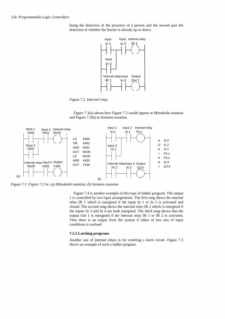
being the detection of the presence of a person and the second part thedetection of whether the barrier is already up or down.
In 2 IR 1
IR 1 Out 1In 4
In 3
In 1Input Input Internal relay
Internal relay
Input
Input Output
Figure 7.2 Internal relay
Figure 7.3(a) shows how Figure 7.2 would appear in Mitsubishi notationand Figure 7.3(b) in Siemens notation.
M100
M100 Y430X403
X400 X401
X402
LDORANDOUTLDANDOUT
X400X402X401M100M100X403Y430
Input 1 Input 2 Internal relay
Input 3
Internal relay Input 5 Output
(a)
I0.1 F0.1
F0.1 Q2.0I0.3
I0.2
I0.0
AOA=AA=
I0.0I0.2I0.1F0.1F0.1I0.3Q2.0
Input 1 Input 2 Internal relay
Input 3
Internal relayInput 3 Output
(b)
Figure 7.3 Figure 7.2 in: (a) Mitsubishi notation, (b) Siemens notation
Figure 7.4 is another example of this type of ladder program. The output1 is controlled by two input arrangements. The first rung shows the internalrelay IR 1 which is energised if the input In 1 or In 2 is activated andclosed. The second rung shows the internal relay IR 2 which is energised ifthe inputs In 3 and In 4 are both energised. The third rung shows that theoutput Out 1 is energised if the internal relay IR 1 or IR 2 is activated.Thus there is an output from the system if either of two sets of inputconditions is realised.
7.2.2 Latching programs
Another use of internal relays is for resetting a latch circuit. Figure 7.5shows an example of such a ladder program.
134 Programmable Logic Controllers
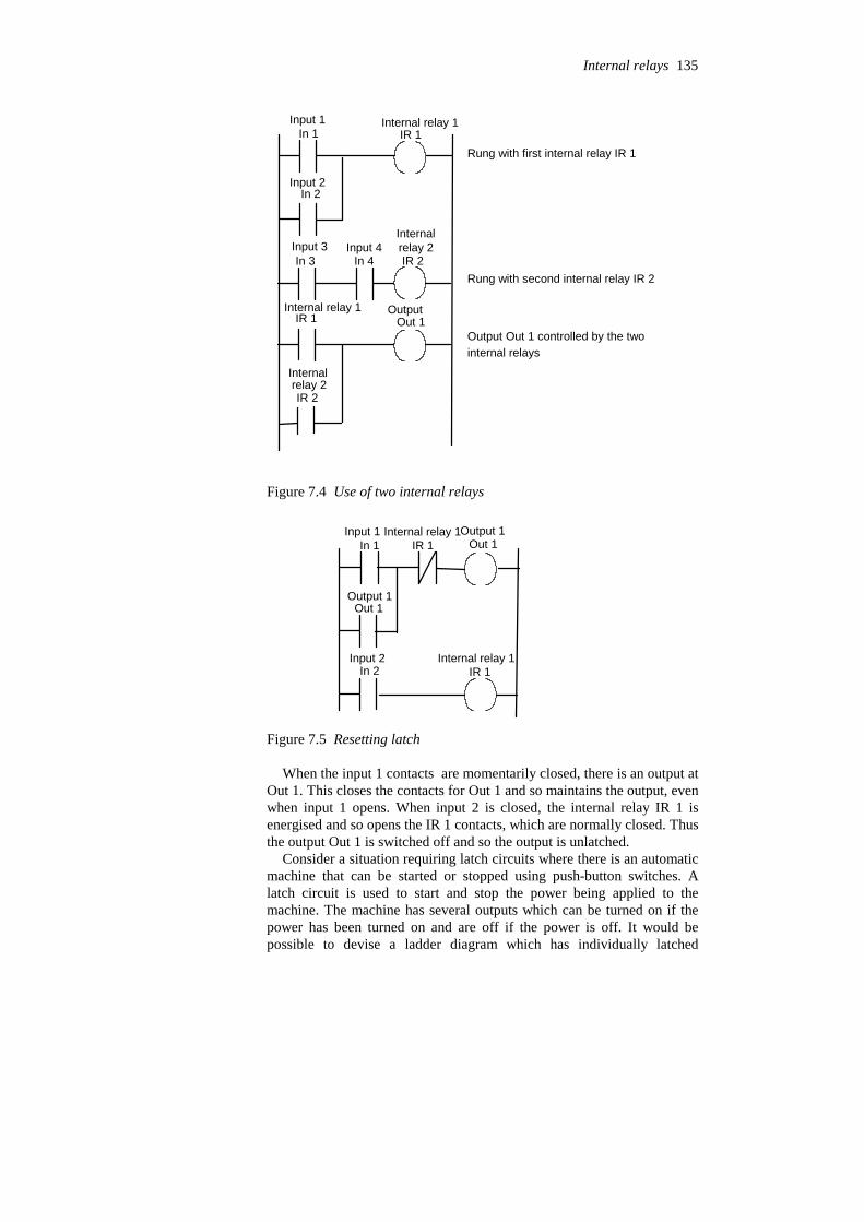
In 1 IR 1
In 2
In 3 In 4 IR 2
Out 1IR 1
IR 2
Rung with first internal relay IR 1
Rung with second internal relay IR 2
Output Out 1 controlled by the two internal relays
Input 1 Internal relay 1
Input 2
Input 3 Input 4Internalrelay 2
OutputInternal relay 1
Internalrelay 2
Figure 7.4 Use of two internal relays
Out 1
IR 1
In 1
In 2
Out 1
IR 1Input 1 Internal relay 1Output 1
Internal relay 1Input 2
Output 1
Figure 7.5 Resetting latch
When the input 1 contacts are momentarily closed, there is an output atOut 1. This closes the contacts for Out 1 and so maintains the output, evenwhen input 1 opens. When input 2 is closed, the internal relay IR 1 isenergised and so opens the IR 1 contacts, which are normally closed. Thusthe output Out 1 is switched off and so the output is unlatched.
Consider a situation requiring latch circuits where there is an automaticmachine that can be started or stopped using push-button switches. Alatch circuit is used to start and stop the power being applied to themachine. The machine has several outputs which can be turned on if thepower has been turned on and are off if the power is off. It would bepossible to devise a ladder diagram which has individually latched
Internal relays 135
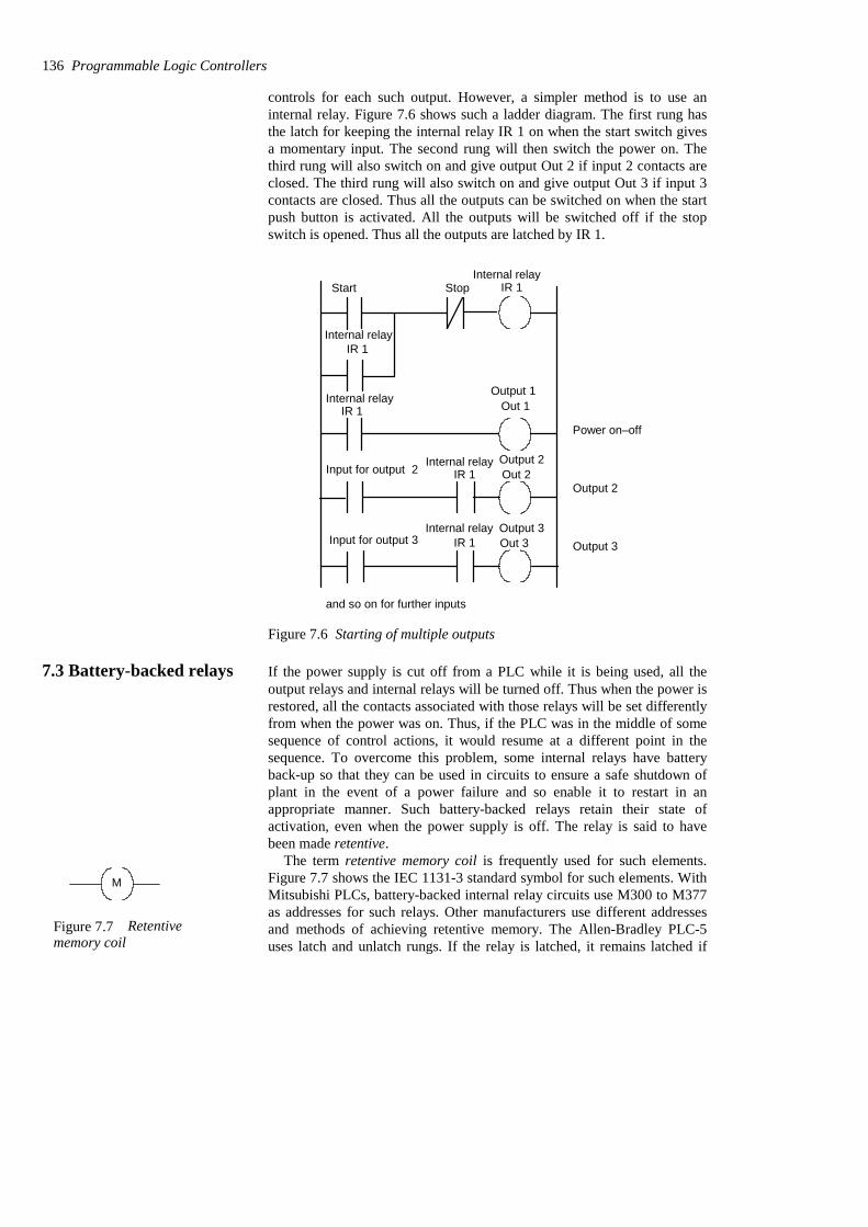
controls for each such output. However, a simpler method is to use aninternal relay. Figure 7.6 shows such a ladder diagram. The first rung hasthe latch for keeping the internal relay IR 1 on when the start switch givesa momentary input. The second rung will then switch the power on. Thethird rung will also switch on and give output Out 2 if input 2 contacts areclosed. The third rung will also switch on and give output Out 3 if input 3contacts are closed. Thus all the outputs can be switched on when the startpush button is activated. All the outputs will be switched off if the stopswitch is opened. Thus all the outputs are latched by IR 1.
Out 3
Start Stop
Input for output 2
Input for output 3
Output 2
Output 3
and so on for further inputs
Out 1IR 1Power on–off
IR 1
IR 1
IR 1
IR 1
Out 2
Internal relay
Output 1
Internal relay
Internal relay
Internal relay
Internal relay
Output 2
Output 3
Figure 7.6 Starting of multiple outputs
7.3 Battery-backed relays If the power supply is cut off from a PLC while it is being used, all theoutput relays and internal relays will be turned off. Thus when the power isrestored, all the contacts associated with those relays will be set differentlyfrom when the power was on. Thus, if the PLC was in the middle of somesequence of control actions, it would resume at a different point in thesequence. To overcome this problem, some internal relays have batteryback-up so that they can be used in circuits to ensure a safe shutdown ofplant in the event of a power failure and so enable it to restart in anappropriate manner. Such battery-backed relays retain their state ofactivation, even when the power supply is off. The relay is said to havebeen made retentive.
The term retentive memory coil is frequently used for such elements.Figure 7.7 shows the IEC 1131-3 standard symbol for such elements. WithMitsubishi PLCs, battery-backed internal relay circuits use M300 to M377as addresses for such relays. Other manufacturers use different addressesand methods of achieving retentive memory. The Allen-Bradley PLC-5uses latch and unlatch rungs. If the relay is latched, it remains latched if
136 Programmable Logic Controllers
M
Figure 7.7 Retentivememory coil

power is lost and is unlatched when the unlatch relay is activated. SeeSection 7.5 for a discussion of such relays in the context of set and resetcoils.
As an example of the use of such a relay, Figure 7.8 shows a ladderdiagram for a system designed to cope with a power failure. IR 1 is abattery-backed internal relay. When input 1 contacts close, output IR 1 isenergised. This closes the IR 1 contacts, latching so that IR 1 remains oneven if input 1 opens. The result is an output from Out 1. If there is apower failure, IR 1 still remains energised and so the IR 1 contacts remainclosed and there is an output from Out 1.
IR 1
IR 1
IR 1
In 1
Out 1
Input Internal relay
Internal relay
Internal relay
Figure 7.8 Battery-backed relay program
7.4 One-shot operation One of the functions provided by some PLC manufacturers is the ability toprogram an internal relay so that its contacts are activated for just onecycle, i.e. one scan through the ladder program. Hence it provides a fixedduration pulse at its contacts when operated. This function is often termedone-shot. While some PLCs have such a function as an entity as part oftheir programs, such a function can easily be developed with just tworungs of a ladder program. Figure 7.9 shows such a pair of rungs. Whenthe trigger input occurs, it gives a trigger output in rung 1. In rung 2 itgives a cycle control output on an internal relay. Because rung 2 occursafter rung 1, the effect of the cycle control is not felt until the next cycleof the PLC program when it opens the cycle control contacts in rung 1 andstops the trigger output. The trigger output then remains off, despite therebeing a trigger input. The trigger output can only occur again when thetrigger output is switched off and then switched on again.
Triggerinput Trigger
input
output
One cycleof PLC program
(a)
Triggeroutput
Triggerinput
Trigger
Cycle control
Cyclecontrol
1
2
ONS
Triggerinput
Triggeroutput
(b)Trigger
input
(c)
PLS
Trigger outputM101
Figure 7.9 One-shot (a) program, (b) facility in an Allen-Bradley PLC, (c) facility in a Mitsubishi PLC
Internal relays 137
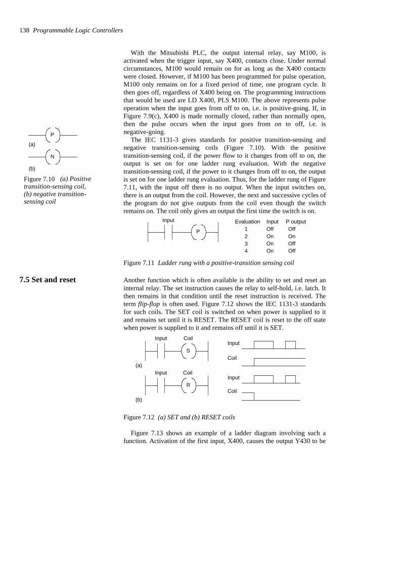
With the Mitsubishi PLC, the output internal relay, say M100, isactivated when the trigger input, say X400, contacts close. Under normalcircumstances, M100 would remain on for as long as the X400 contactswere closed. However, if M100 has been programmed for pulse operation,M100 only remains on for a fixed period of time, one program cycle. Itthen goes off, regardless of X400 being on. The programming instructionsthat would be used are LD X400, PLS M100. The above represents pulseoperation when the input goes from off to on, i.e. is positive-going. If, inFigure 7.9(c), X400 is made normally closed, rather than normally open,then the pulse occurs when the input goes from on to off, i.e. isnegative-going.
The IEC 1131-3 gives standards for positive transition-sensing andnegative transition-sensing coils (Figure 7.10). With the positivetransition-sensing coil, if the power flow to it changes from off to on, theoutput is set on for one ladder rung evaluation. With the negativetransition-sensing coil, if the power to it changes from off to on, the outputis set on for one ladder rung evaluation. Thus, for the ladder rung of Figure7.11, with the input off there is no output. When the input switches on,there is an output from the coil. However, the next and successive cycles ofthe program do not give outputs from the coil even though the switchremains on. The coil only gives an output the first time the switch is on.
P
Input Evaluation Input P output1234
OffOnOnOn
OffOnOffOff
Figure 7.11 Ladder rung with a positive-transition sensing coil
7.5 Set and reset Another function which is often available is the ability to set and reset aninternal relay. The set instruction causes the relay to self-hold, i.e. latch. Itthen remains in that condition until the reset instruction is received. Theterm flip-flop is often used. Figure 7.12 shows the IEC 1131-3 standardsfor such coils. The SET coil is switched on when power is supplied to itand remains set until it is RESET. The RESET coil is reset to the off statewhen power is supplied to it and remains off until it is SET.
S
R
Input
Input(a)
(b)
Input
Coil
Input
Coil
Coil
Coil
Figure 7.12 (a) SET and (b) RESET coils
Figure 7.13 shows an example of a ladder diagram involving such afunction. Activation of the first input, X400, causes the output Y430 to be
138 Programmable Logic Controllers
P
N
(a)
(b)
Figure 7.10 (a) Positivetransition-sensing coil,(b) negative transition-sensing coil
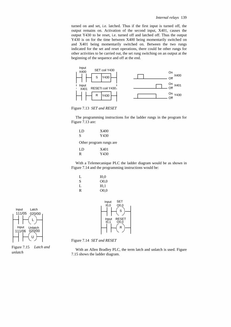
turned on and set, i.e. latched. Thus if the first input is turned off, theoutput remains on. Activation of the second input, X401, causes theoutput Y430 to be reset, i.e. turned off and latched off. Thus the outputY430 is on for the time between X400 being momentarily switched onand X401 being momentarily switched on. Between the two rungsindicated for the set and reset operations, there could be other rungs forother activities to be carried out, the set rung switching on an output at thebeginning of the sequence and off at the end.
Y430
R Y430
X400
X401
S Off
On
OnOff
OnOff
X400
X401
Y430
InputSET coil Y430
InputRESETt coil Y430
Figure 7.13 SET and RESET
The programming instructions for the ladder rungs in the program forFigure 7.13 are:
Y430RX401LD
Other program rungs are
Y430SX400LD
With a Telemecanique PLC the ladder diagram would be as shown inFigure 7.14 and the programming instructions would be:
O0,0RI0,1LO0,0SI0,0L
I0,0
I0,1
O0,0
O0,0
S
R
Input SET
Input RESET
Figure 7.14 SET and RESET
With an Allen Bradley PLC, the term latch and unlatch is used. Figure7.15 shows the ladder diagram.
Internal relays 139
111/05
111/06
Figure 7.15 Latch andunlatch
L
U
020/00
020/00
Input Latch
Input Unlatch

The SET and RESET coil symbols are often combined into a single boxsymbol. Figure 7.16 shows the equivalent ladder diagram for the set-resetfunction in the above Figures with a Siemens PLC. The term memory boxis used by them for the SET/RESET box, the box shown is termed a SR orreset priority memory function in that reset has priority. The programminginstructions (F being used to indicate an internal relay) are:
Q2.0=F0.0AF0.0RI0.1AF0.0SI0.0A
S
R
Q2.0
I0.0
I0.1
F0.0Input 1 SR Memory
Input 2Output
Reset priority
Set input 1, reset input 0there is outputSet input 0, reset input 1there is no outputSet input 1, reset input 1there is no outputSet input 0, reset input 0there is no output
Input 1
Input 2
Output
Figure 7.16 SET and RESET, with reset priority
With set priority (RS memory box), the arrangement is as shown in Figure7.17.
R
S
Q2.0I0.0
I0.1
F0.0Input 1 RS Memory
Input 2
Output Set priority
Set input 1, reset input 0there is outputSet input 0, reset input 1there is no outputSet input 1, reset input 1there is outputSet input 0, reset input 0there is no output
Input 1
Input 2
Output
Figure 7.17 SET and RESET, with reset priority
140 Programmable Logic Controllers
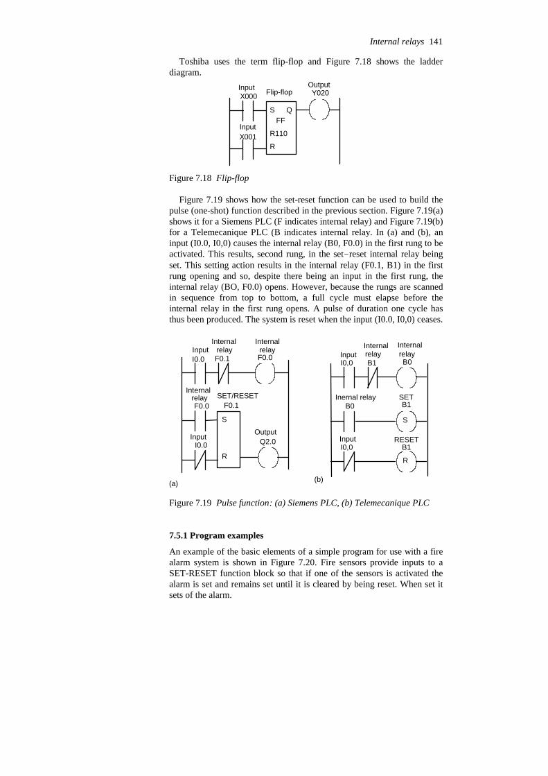
Toshiba uses the term flip-flop and Figure 7.18 shows the ladderdiagram.
X000
X001
S
R
FF
R110
Q
Y020Input Flip-flop
Output
Input
Figure 7.18 Flip-flop
Figure 7.19 shows how the set-reset function can be used to build thepulse (one-shot) function described in the previous section. Figure 7.19(a)shows it for a Siemens PLC (F indicates internal relay) and Figure 7.19(b)for a Telemecanique PLC (B indicates internal relay. In (a) and (b), aninput (I0.0, I0,0) causes the internal relay (B0, F0.0) in the first rung to beactivated. This results, second rung, in the set-reset internal relay beingset. This setting action results in the internal relay (F0.1, B1) in the firstrung opening and so, despite there being an input in the first rung, theinternal relay (BO, F0.0) opens. However, because the rungs are scannedin sequence from top to bottom, a full cycle must elapse before theinternal relay in the first rung opens. A pulse of duration one cycle hasthus been produced. The system is reset when the input (I0.0, I0,0) ceases.
I0.0 F0.1 F0.0
F0.1F0.0
I0.0
S
R
Q2.0
I0,0 B1 B0
B0 B1
I0,0 B1
S
R
(a) (b)
InputInternal relay
Internalrelay
SETInernal relay
RESETInput
Input
Output
Internalrelay
Internalrelay
Internalrelay SET/RESET
Input
Figure 7.19 Pulse function: (a) Siemens PLC, (b) Telemecanique PLC
7.5.1 Program examples
An example of the basic elements of a simple program for use with a firealarm system is shown in Figure 7.20. Fire sensors provide inputs to aSET-RESET function block so that if one of the sensors is activated thealarm is set and remains set until it is cleared by being reset. When set itsets of the alarm.
Internal relays 141
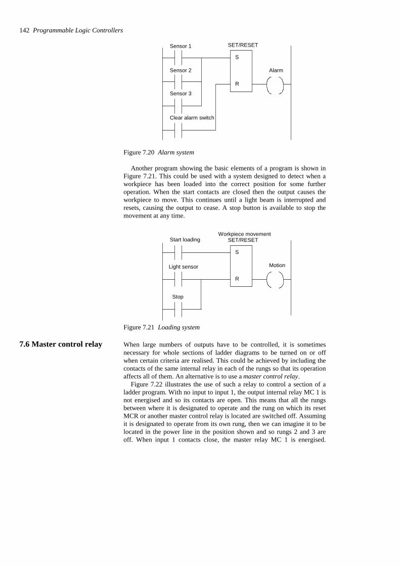
Alarm
S
R
Sensor 1
Sensor 2
Sensor 3
Clear alarm switch
SET/RESET
Figure 7.20 Alarm system
Another program showing the basic elements of a program is shown inFigure 7.21. This could be used with a system designed to detect when aworkpiece has been loaded into the correct position for some furtheroperation. When the start contacts are closed then the output causes theworkpiece to move. This continues until a light beam is interrupted andresets, causing the output to cease. A stop button is available to stop themovement at any time.
Motion
S
R
Start loading
Light sensor
Stop
SET/RESETWorkpiece movement
Figure 7.21 Loading system
7.6 Master control relay When large numbers of outputs have to be controlled, it is sometimesnecessary for whole sections of ladder diagrams to be turned on or offwhen certain criteria are realised. This could be achieved by including thecontacts of the same internal relay in each of the rungs so that its operationaffects all of them. An alternative is to use a master control relay.
Figure 7.22 illustrates the use of such a relay to control a section of aladder program. With no input to input 1, the output internal relay MC 1 isnot energised and so its contacts are open. This means that all the rungsbetween where it is designated to operate and the rung on which its resetMCR or another master control relay is located are switched off. Assumingit is designated to operate from its own rung, then we can imagine it to belocated in the power line in the position shown and so rungs 2 and 3 areoff. When input 1 contacts close, the master relay MC 1 is energised.
142 Programmable Logic Controllers
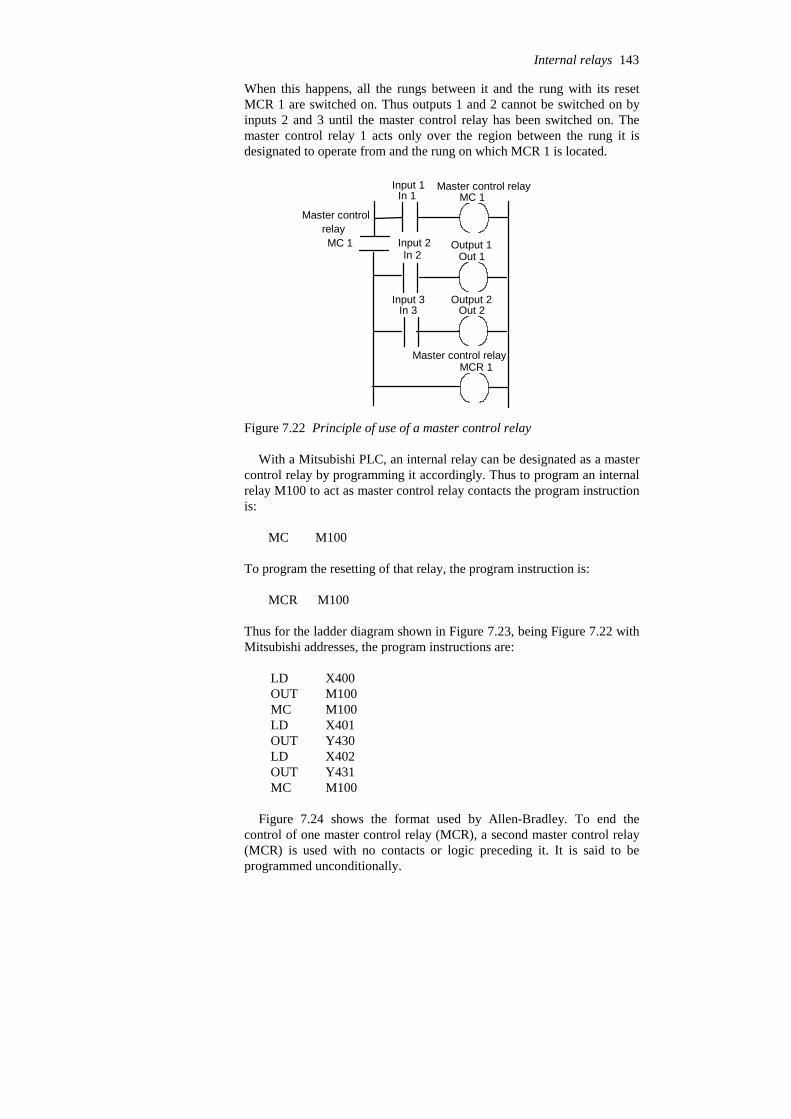
When this happens, all the rungs between it and the rung with its resetMCR 1 are switched on. Thus outputs 1 and 2 cannot be switched on byinputs 2 and 3 until the master control relay has been switched on. Themaster control relay 1 acts only over the region between the rung it isdesignated to operate from and the rung on which MCR 1 is located.
In 1
In 2
In 3
MC 1
MCR 1
Out 1
Out 2
MC 1
Input 1
Input 2
Input 3
Output 1
Output 2
Master control relay
Master control relay
Master control relay
Figure 7.22 Principle of use of a master control relay
With a Mitsubishi PLC, an internal relay can be designated as a mastercontrol relay by programming it accordingly. Thus to program an internalrelay M100 to act as master control relay contacts the program instructionis:
MC M100
To program the resetting of that relay, the program instruction is:
MCR M100
Thus for the ladder diagram shown in Figure 7.23, being Figure 7.22 withMitsubishi addresses, the program instructions are:
M100MCY431OUTX402LDY430OUTX401LDM100MCM100OUTX400LD
Figure 7.24 shows the format used by Allen-Bradley. To end thecontrol of one master control relay (MCR), a second master control relay(MCR) is used with no contacts or logic preceding it. It is said to beprogrammed unconditionally.
Internal relays 143

X400
X401
X402
M100
MCR 1
Y430
Y431
M100
Input 1
Input 2
Input 3
Output 1
Output 2
Master control relay
Master control relay
Master control relay
MCR M100
Mastercontrolrelayfor theserungs
Mastercontrolrelay fortheserungs
I:010/01
I:010/02
I:010/03
MCR
MCR
O:010/00
O:010/01
Input 1
Input 2
Input 3
Output 1
Output 2
Master control relay
Master control relay
Figure 7.23 MCR with Mitsubishi PLC Figure 7.24 MCR with Allen-Bradley PLC
The representation used in Siemens ladder programs for master controlrelays is shown in Figure 7.25. An area in which a master control relay isto operate is defined by the activate master control area and deactivatemaster control relay functions. Within that area, the master control relay isenabled when MCR> coil is activated and disabled when the MCR< coil isenabled.
MCRA Activate the master control relay area
MCRD Deactivate the master control relay area
MCR<
MCR>
Open the MCR zone
Clear the MCR zone
Figure 7.25 Siemens representation of master control relays
A program might use a number of master control relays, enablingvarious sections of a ladder program to be switched in or out. Figure 7.26shows a ladder program in Mitsubishi format involving two master controlrelays. With M100 switched on, but M101 off, the sequence is: rungs 1, 3,4, 6, etc. The end of the M100 controlled section is indicated by theoccurrence of the other master control relay, M101. With M101 switchedon, but M100 off, the sequence is: rungs 2, 4, 5, 6, etc. The end of thissection is indicated by the presence of the reset. This reset has to be usedsince the rung is not followed immediately by another master control relay.Such an arrangement could be used to switch on one set of ladder rungs ifone type of input occurs, and another set of ladder rungs if a different inputoccurs.
144 Programmable Logic Controllers
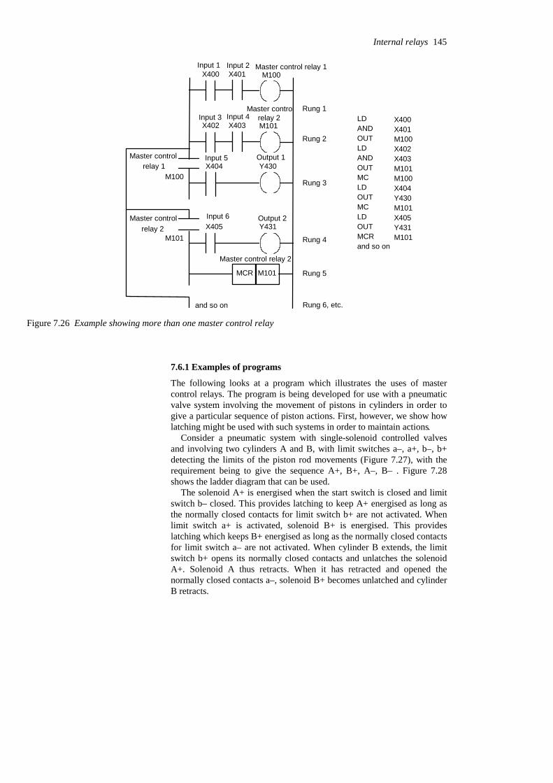
MCR M101
X400 X401 M100
X402 X403 M101
M100X404 Y430
M101X405 Y431
and so on
Rung 1
Rung 2
Rung 3
Rung 4
Rung 5
Rung 6, etc.
Input 1 Input 2 Master control relay 1
Input 3 Input 4Master control
relay 2
Input 5 Output 1
Output 2Input 6
Master control relay 2
Master control relay 1
Master controlrelay 2
LDANDOUTLDANDOUTMCLDOUTMCLDOUTMCRand so on
X400X401M100X402X403M101M100X404Y430M101X405Y431M101
Figure 7.26 Example showing more than one master control relay
7.6.1 Examples of programs
The following looks at a program which illustrates the uses of mastercontrol relays. The program is being developed for use with a pneumaticvalve system involving the movement of pistons in cylinders in order togive a particular sequence of piston actions. First, however, we show howlatching might be used with such systems in order to maintain actions.
Consider a pneumatic system with single-solenoid controlled valvesand involving two cylinders A and B, with limit switches a–, a+, b–, b+detecting the limits of the piston rod movements (Figure 7.27), with therequirement being to give the sequence A+, B+, A–, B– . Figure 7.28shows the ladder diagram that can be used.
The solenoid A+ is energised when the start switch is closed and limitswitch b– closed. This provides latching to keep A+ energised as long asthe normally closed contacts for limit switch b+ are not activated. Whenlimit switch a+ is activated, solenoid B+ is energised. This provideslatching which keeps B+ energised as long as the normally closed contactsfor limit switch a– are not activated. When cylinder B extends, the limitswitch b+ opens its normally closed contacts and unlatches the solenoidA+. Solenoid A thus retracts. When it has retracted and opened thenormally closed contacts a–, solenoid B+ becomes unlatched and cylinderB retracts.
Internal relays 145

A B
a– a+ b– b+
A+ B+
Figure 7.27 Valve system
END
Start b– A+
A+ b+
a+
B+ a–
B+
Cylinder A extends,latched until b+activated
Cylinder B extends,latched until a–activated
Limit switch Solenoid
Solenoid Limit switch
Limit switch
Solenoid
solenoid
Limitswitch
Figure 7.28 Ladder program
Now consider the ladder program which could be used with the pair ofsingle-solenoid-controlled cylinders in Figure 7.27 to give, when and onlywhen the start switch is momentarily triggered, the sequence A+, B+, A–,10 s time delay, B– and stop at that point until the start switch is triggeredagain. Figure 7.29 shows how such a program can be devised using amaster control relay. The master control relay is activated by the startswitch and remains on until switched off by the rung containing just MCR.
Problems Questions 1 to 21 have four answer options: A, B, C or D. Choose thecorrect answer from the answer options.
Problems 1 to 3 refer to Figure 7.30 which shows a ladder diagramwith an internal relay, designated IR 1, two inputs In 1 and In 2, andan output Output 1.
146 Programmable Logic Controllers
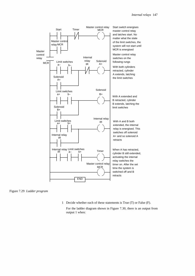
TimerStart MCR
MCR
MCR a– b– IR A+
A+
a+ b– B+
B+
a+ b+ IR
IR
IR a– b+ Timer
MCR
END
Master control relayswitches on thefollowing rungs
With both cylindersretracted, cylinderA extends, latchingthe limit switches
With A extended andB retracted, cylinderB extends, latching the limit switches
With A and B bothextended, the internalrelay is energised. Thisswitches off solenoidA+ and so solenoid Aretracts
When A has retracted,cylinder B still extended,activating the internalrelay switches thetimer on. After the settime the system isswitched off and Bretracts
Start switch energisesmaster control relayand latches start. Nomatter what the stateof the limit switches, thesystem will not start untilMCR is energised
Master control relay
Mastercontrolrelay
Master control relay
Internal relay
Internal relay
Internal relay Limit switches
Limit switches
Solenoid
SolenoidInternalrelayLimit switches
Solenoid
Limit switches
Solenoid
Master controlrelay
Figure 7.29 Ladder program
1 Decide whether each of these statements is True (T) or False (F).
For the ladder diagram shown in Figure 7.30, there is an output fromoutput 1 when:
Internal relays 147
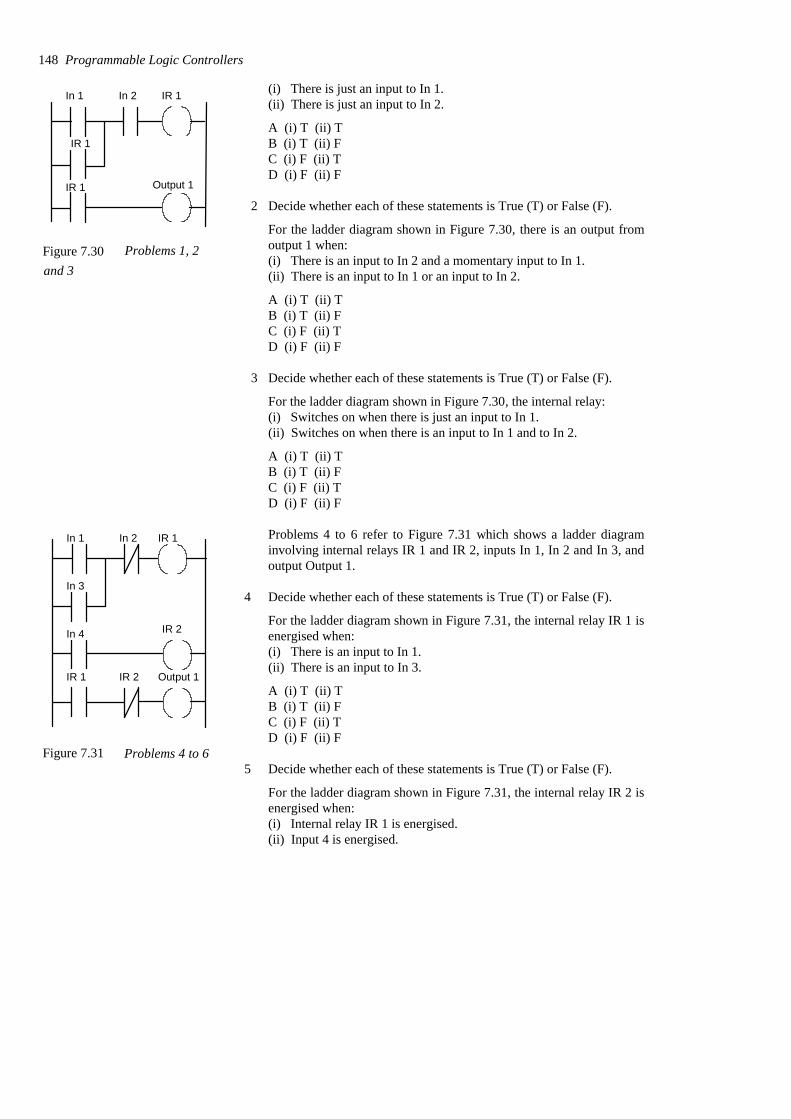
(i) There is just an input to In 1.(ii) There is just an input to In 2.
A (i) T (ii) TB (i) T (ii) FC (i) F (ii) TD (i) F (ii) F
2 Decide whether each of these statements is True (T) or False (F).
For the ladder diagram shown in Figure 7.30, there is an output fromoutput 1 when:(i) There is an input to In 2 and a momentary input to In 1.(ii) There is an input to In 1 or an input to In 2.
A (i) T (ii) TB (i) T (ii) FC (i) F (ii) TD (i) F (ii) F
3 Decide whether each of these statements is True (T) or False (F).
For the ladder diagram shown in Figure 7.30, the internal relay:(i) Switches on when there is just an input to In 1.(ii) Switches on when there is an input to In 1 and to In 2.
A (i) T (ii) TB (i) T (ii) FC (i) F (ii) TD (i) F (ii) F
Problems 4 to 6 refer to Figure 7.31 which shows a ladder diagraminvolving internal relays IR 1 and IR 2, inputs In 1, In 2 and In 3, andoutput Output 1.
4 Decide whether each of these statements is True (T) or False (F).
For the ladder diagram shown in Figure 7.31, the internal relay IR 1 isenergised when:(i) There is an input to In 1.(ii) There is an input to In 3.
A (i) T (ii) TB (i) T (ii) FC (i) F (ii) TD (i) F (ii) F
5 Decide whether each of these statements is True (T) or False (F).
For the ladder diagram shown in Figure 7.31, the internal relay IR 2 isenergised when:(i) Internal relay IR 1 is energised.(ii) Input 4 is energised.
148 Programmable Logic Controllers
In 1 In 2 IR 1
IR 1
IR 1 Output 1
Figure 7.30 Problems 1, 2 and 3
In 1 In 2 IR 1
In 3
In 4 IR 2
IR 1 IR 2 Output 1
Figure 7.31 Problems 4 to 6
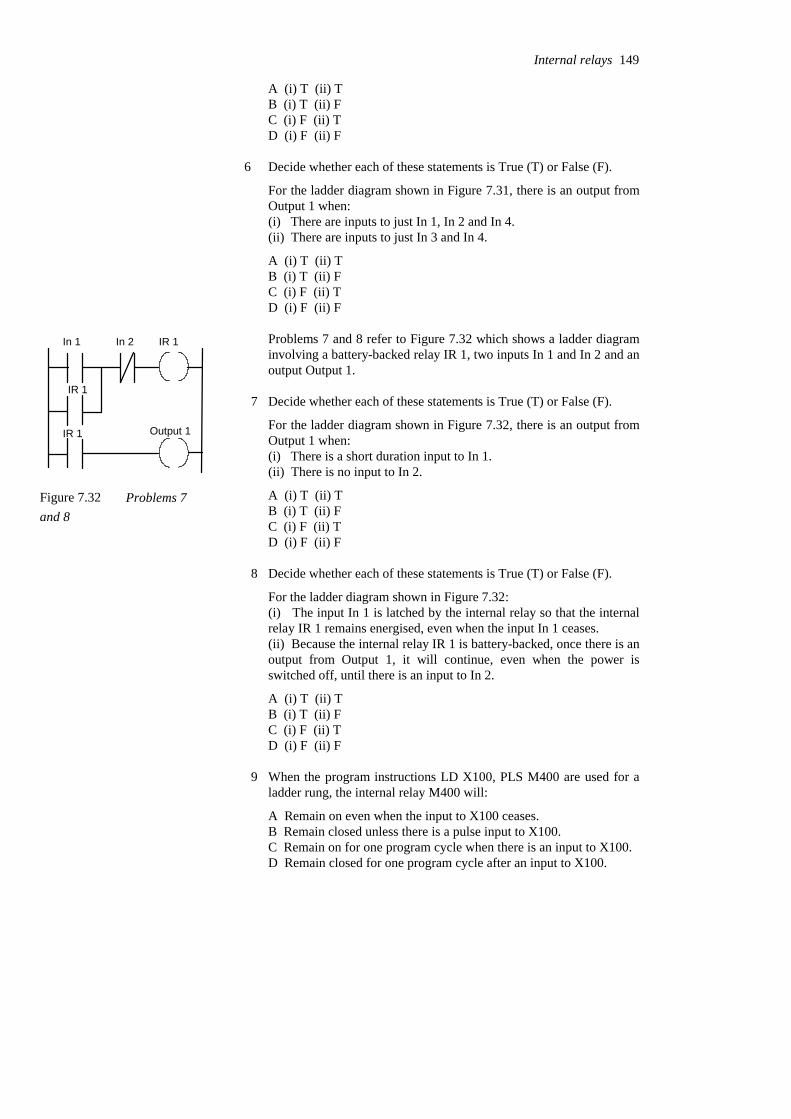
A (i) T (ii) TB (i) T (ii) FC (i) F (ii) TD (i) F (ii) F
6 Decide whether each of these statements is True (T) or False (F).
For the ladder diagram shown in Figure 7.31, there is an output fromOutput 1 when:(i) There are inputs to just In 1, In 2 and In 4.(ii) There are inputs to just In 3 and In 4.
A (i) T (ii) TB (i) T (ii) FC (i) F (ii) TD (i) F (ii) F
Problems 7 and 8 refer to Figure 7.32 which shows a ladder diagraminvolving a battery-backed relay IR 1, two inputs In 1 and In 2 and anoutput Output 1.
7 Decide whether each of these statements is True (T) or False (F).
For the ladder diagram shown in Figure 7.32, there is an output fromOutput 1 when:(i) There is a short duration input to In 1.(ii) There is no input to In 2.
A (i) T (ii) TB (i) T (ii) FC (i) F (ii) TD (i) F (ii) F
8 Decide whether each of these statements is True (T) or False (F).
For the ladder diagram shown in Figure 7.32:(i) The input In 1 is latched by the internal relay so that the internalrelay IR 1 remains energised, even when the input In 1 ceases.(ii) Because the internal relay IR 1 is battery-backed, once there is anoutput from Output 1, it will continue, even when the power isswitched off, until there is an input to In 2.
A (i) T (ii) TB (i) T (ii) FC (i) F (ii) TD (i) F (ii) F
9 When the program instructions LD X100, PLS M400 are used for aladder rung, the internal relay M400 will:
A Remain on even when the input to X100 ceases.B Remain closed unless there is a pulse input to X100.C Remain on for one program cycle when there is an input to X100.D Remain closed for one program cycle after an input to X100.
Internal relays 149
In 1 In 2 IR 1
IR 1
IR 1 Output 1
Figure 7.32 Problems 7and 8

10 When the program instructions LDI X100, PLS M400 are used for aladder rung, the internal relay M400 will:
A Remain on when the input to X100 ceases.B Remain on when there is a pulse input to X100.C Remain on for one program cycle when there is an input to X100.D Remain on for one program cycle after the input to X100 ceases.
11 A Mitsubishi ladder program has the program instructions LD X100, SM200, LD X101, R M200, followed by other instructions for furtherrungs. There is the sequence: an input to the input X100, the input toX100 ceases, some time elapses, an input to the input X101, the inputto X101 ceases, followed by inputs to later rungs. The internal relayM200 will remain on:
A For one program cycle from the start of the input to X100.B From the start of the input to X100 to the start of the input to
X101.C From the start of the input to X100 to the end of the input to
X101.D From the end of the input to X100 to the end of the input to X101.
12 A Siemens ladder program has the program instructions A I0.0, SF0.0, A I0.1, R F0.0, A F0.0, = Q2.0, followed by other instructionsfor further rungs. There is the sequence: an input to the input I0.0, theinput to I0.0 ceases, some time elapses, an input to the input I0.1, theinput to I0.1 ceases, followed by inputs to later rungs. The internalrelay F0.0 will remain on:
A For one program cycle from the start of the input to I0.0.B From the start of the input to I0.0 to the start of the input to I0.1.C From the start of the input to I0.0 to the end of the input to I0.1.D From the end of the input to I0.0 to the end of the input to I0.1.
13 A Telemecanique ladder program has the program instructions L I0,0,S O0,0, L I0,1, R O0,0, followed by other instructions for furtherrungs. There is the sequence: an input to the input I0,0, the input toI0,0 ceases, some time elapses, an input to the input I0,1, the input toI0,1 ceases, followed by inputs to later rungs. The internal relay O0,0will remain on:
A For one program cycle from the start of the input to I0,0.B From the start of the input to I0,0 to the start of the input to I0,1.C From the start of the input to I0,0 to the end of the input to I0,1.D From the end of the input to I0,0 to the end of the input to I0,1.
14 An output is required from output Y430 which lasts for one cycle afteran input to X100 starts. This can be given by a ladder program withthe instructions:
A LD X100, Y430B LD X100, M100, LD M100, Y 430
150 Programmable Logic Controllers

C LD X100, PLS M100, LD M100, Y 430D LD X400, PLS M100, LDI M100, Y430
Questions 15 and 16 refer to Figure 7.33, which are two versions ofthe same ladder diagram according to two different PLCmanufacturers. In (a) which uses Siemens notation, I is used forinputs, F for internal relays and Q for the output. In (b) which usesTelemecanique notation, I is used for inputs and B for internal relays.
I0.0 F0.1 F0.0
F0.1F0.0
I0.0
S
R
Q2.0
I0,0 B1 B0
B0 B1
I0,0 B1
S
R
(a) (b)
Figure 7.33 Problems 15 and 16
15 For the ladder diagram shown in Figure 7.33(a), when there is aninput to I0.0, the output Q2.0:
A Comes on and remains on for one cycle.B Comes on and remains on.C Goes off and remains off for one cycle.D Goes off and remains off.
16 For the ladder diagram shown in Figure 7.33(b), when there is aninput to I0,0, the internal relay B1:
A Comes on and remains on for one cycle.B Comes on and remains on.C Goes off and remains off for one cycle.D Goes off and remains off.
Problems 17 and 18 refer to Figure 7.34 which shows a Toshibaladder program with inputs X000, X001 and X002, an output Y020and a flip- flop R110.
X000 X001
X002
S
R
FFR110
Y020
Figure 7.34 Problems 17 and 18
Internal relays 151
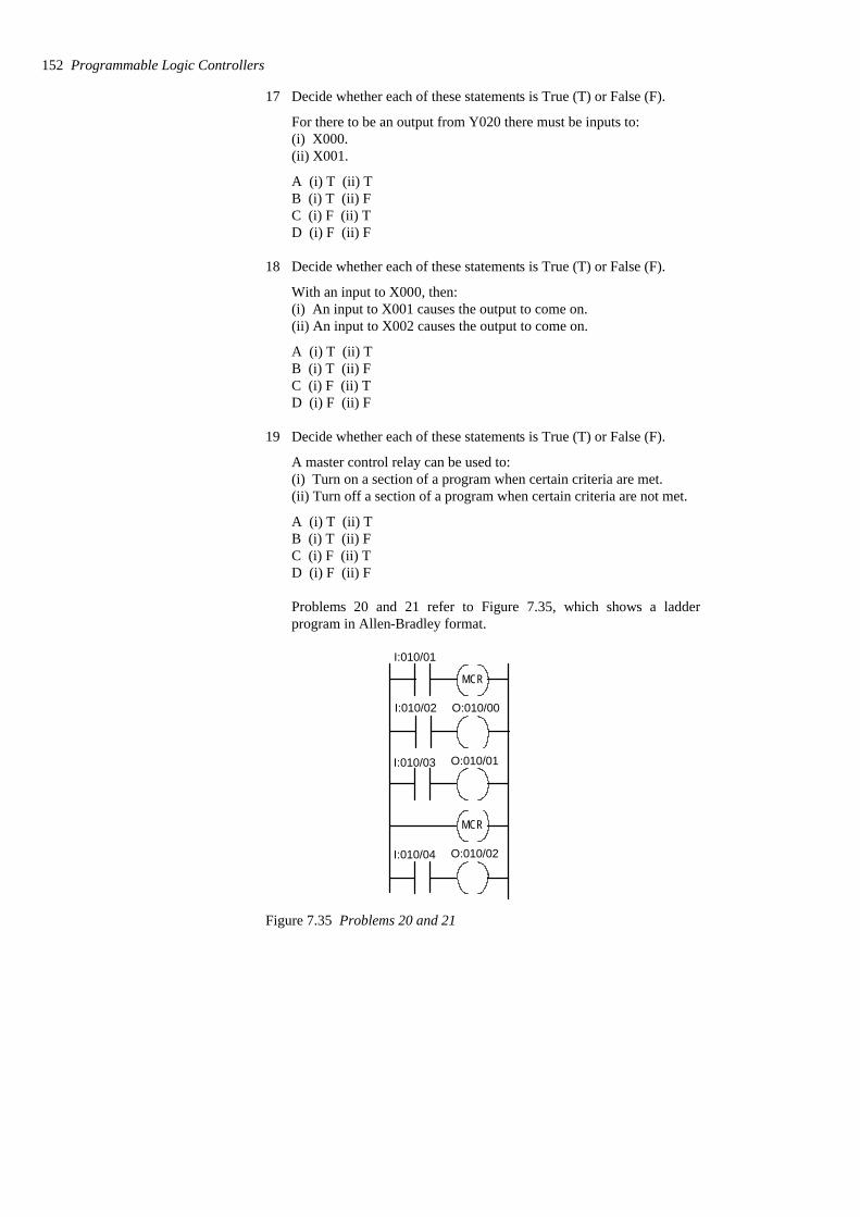
17 Decide whether each of these statements is True (T) or False (F).
For there to be an output from Y020 there must be inputs to:(i) X000.(ii) X001.
A (i) T (ii) TB (i) T (ii) FC (i) F (ii) TD (i) F (ii) F
18 Decide whether each of these statements is True (T) or False (F).
With an input to X000, then:(i) An input to X001 causes the output to come on.(ii) An input to X002 causes the output to come on.
A (i) T (ii) TB (i) T (ii) FC (i) F (ii) TD (i) F (ii) F
19 Decide whether each of these statements is True (T) or False (F).
A master control relay can be used to:(i) Turn on a section of a program when certain criteria are met.(ii) Turn off a section of a program when certain criteria are not met.
A (i) T (ii) TB (i) T (ii) FC (i) F (ii) TD (i) F (ii) F
Problems 20 and 21 refer to Figure 7.35, which shows a ladderprogram in Allen-Bradley format.
I:010/01
I:010/02
I:010/03
MCR
MCR
O:010/00
O:010/01
I:010/04 O:010/02
Figure 7.35 Problems 20 and 21
152 Programmable Logic Controllers
20 Decide whether each of these statements is True (T) or False (F).
When there is an input to I:010/01:(i) An input to I:010/02 gives an output from O:010/00.(ii) An input to I:010/03 gives an output from O:010/01.
A (i) T (ii) TB (i) T (ii) FC (i) F (ii) TD (i) F (ii) F
21 Decide whether each of these statements is True (T) or False (F).
When there is no input to I:010/01:(i) An input to I:010/02 gives no output from O:010/00.(ii) An input to I:010/04 gives no output from O:010/02.
A (i) T (ii) TB (i) T (ii) FC (i) F (ii) TD (i) F (ii) F
22 Devise ladder programs which can be used to:(a) Maintain an output on, even when the input ceases and when thereis a power failure.(b) Switch on an output for a time of one cycle following a briefinput.(c) Switch on the power to a set of rungs.
Internal relays 153
8 Jump and call
This chapter considers the jump instruction which enables part of aprogram to be jumped over and the way in which subroutines in ladderprogrammes can be called up. Subroutines enable commonly occurringoperations in a program to be repeatedly called up and used over again.
8.1 Jump A function often provided with PLCs is the conditional jump. We candescribe this as:
IF (some condition occurs) THENperform some instructions
ELSEperform some other instructions.
Such a facility enables programs to be designed such that if certainconditions are met then certain events occur, if they are not met then otherevents occur. Thus, for example, we might need to design a system so thatif the temperature is above 60oC a fan is switched on, and if below thattemperature no action occurs.
Thus, if the appropriate conditions are met, this function enables part ofa ladder program to be jumped over. Figure 8.1 illustrates this in a generalmanner. When there is an input to In 1, its contacts close and there is anoutput to the jump relay. This then results in the program jumping to therung in which the jump end occurs, so missing out intermediate programrungs. Thus, in this case, when there is an input to Input 1, the programjumps to rung 4 and then proceeds with rungs 5, 6, etc. When there is noinput to Input 1, the jump relay is not energised and the program thenproceeds to rungs 2, 3, etc.
Figure 8.2(a) shows the above ladder program in the form used byMitsubishi. The jump instruction is denoted by CJP (conditional jump) andthe place to which the jump occurs is denoted by EJP (end of jump). Thecondition that the jump will occur is then that there is an input to X400.When that happens the rungs involving inputs X401 and X403 are ignoredand the program jumps to continue with the rungs following the end jumpinstruction with the same number as the start jump instruction, i.e. in thiscase EJP 700.
With the Allen-Bradley PLC-5 format the jump takes place from thejump instruction (JMP) to the label instruction (LBL). The JMP instructionis given a three-digit number from 000 to 255 and the LBL instruction thesame number. Figure 8.2(b) shows a ladder program in this format.
Input 1 Jump
Jump end
Rung 1
Rung 2
Rung 3
Rung 4
etc.Figure 8.1 Jump
X400
X401
X402
Y430
Y431
CJP 700
EJP 700
Input 1
Input 2
Input 3
Output 1
Output 2
Jump betweenthese rungsof the programif input 1 occurs
JMP
LBL
I:012/10
I:012/11
I:012/12
010
010
O:012/10
O:012/11
O:012/12
Jump if input
Input Jump
Label Output
I:012/10 occurs
(a) (b)
Figure 8.2 Jump: (a) Mitsubishi program, (b) Allen-Bradley program
With Siemens’ programs, conditional jumps are represented as shownin Figure 8.3, there being a jump instruction JMP which is executed if theinput is a 1 and another jump instruction JMPN which is executed if theinput is 0. The end of both instructions is the label DEST.
JMP Jump if input 1
JMPN Jump if input 0
DEST End of jump
Figure 8.3 Siemens’ jump instructions
8.1.1 Jumps within jumps
Jumps within jumps are possible. For example, we might have thesituation shown in Figure 8.4. If the condition for the jump instruction 1 isrealised then the program jumps to rung 8. If the condition is not met thenthe program continues to rung 3. If the condition for the jump instruction2 is realised then the program jumps to rung 6. If the condition is not metthen the program continues through the rungs.
Thus if we have an input to In 1, the rung sequence is rung 1, 8, etc. Ifwe have no input to In 1 but an input to In 3, then the rung sequence is 1,2, 6, 7, 8, etc. If we have no input to In 1 and no input to In 3, the rungsequence is 1, 2, 3, 4, 5, 6, 7, 8, etc. The jump instruction enablesdifferent groups of program rungs to be selected, depending on theconditions occurring.
Jump and call 155
Rung 1
Rung 2
Rung 3
Rung 4
Rung 5
Rung 6
Rung 7
Rung 8
Jump 1
Jump 2
In 1
In 3
Jump 2 end
Jump 1 end
If In 1
If In 3
Figure 8.4 Jumps within jumps
8.2 Subroutines Subroutines are small programs to perform specific tasks which can becalled for use in larger programs. Thus with a Mitsubishi program wemight have the situation shown in Figure 8.5(a). When input 1 occurs, thesubroutine P is called. This is then executed, the instruction SRETindicating its end and the point at which the program returns to the mainprogram. To clearly indicate where the main program ends the FENDinstruction is used.
With Allen-Bradley, subroutines are called by using a jump-to-subroutine JSR instruction, the start of the subroutine being indicated bySBR and its end and point of return to the main program by RET (Figure8.5(b)).
With Siemens a similar format can be adopted, using CALL to call up asubroutine block and RET to indicate the return instruction to the mainprogram. However, a function box approach (Figure 8.6) can be used andis particularly useful where there is a library of subroutine functions to becalled. If the EN (enable) block input is connected directly to the leftpower rail then the call is without conditions and always executed. If thereis a logic operation preceding EN then the block call is only executed if thelogic condition is fulfilled, in Figure 8.6 this is closure of contacts of Input1. Several blocks can be connected in series by connecting the ENO,enable output, of one to the EN input of the next.
156 Programmable Logic Controllers
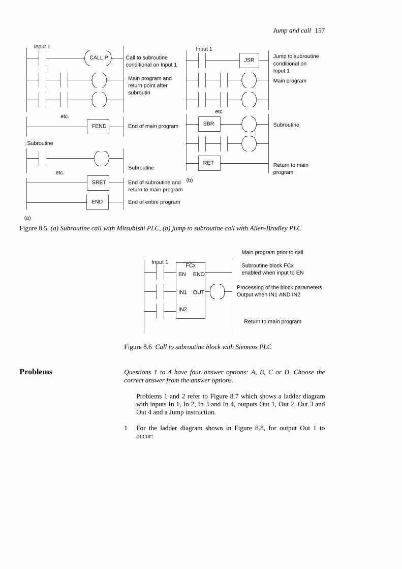
Input 1
CALL P
Main program and
Call to subroutine
etc.
FEND End of main program
; Subroutine
etc.
SRET
Subroutine
END End of entire program
End of subroutine andreturn to main program
JSR
etc
Jump to subroutine
Main program
SBR
RET
Subroutine
Return to main program
(a)
return point aftersubroutin
(b)
conditional on Input 1
Input 1
conditional on Input 1
Figure 8.5 (a) Subroutine call with Mitsubishi PLC, (b) jump to subroutine call with Allen-Bradley PLC
Subroutine block FCx
Return to main program
FCxEN
IN1
IN2
OUT
ENO enabled when input to EN
Main program prior to call
Processing of the block parametersOutput when IN1 AND IN2
Input 1
Figure 8.6 Call to subroutine block with Siemens PLC
Problems Questions 1 to 4 have four answer options: A, B, C or D. Choose thecorrect answer from the answer options.
Problems 1 and 2 refer to Figure 8.7 which shows a ladder diagramwith inputs In 1, In 2, In 3 and In 4, outputs Out 1, Out 2, Out 3 andOut 4 and a Jump instruction.
1 For the ladder diagram shown in Figure 8.8, for output Out 1 tooccur:
Jump and call 157
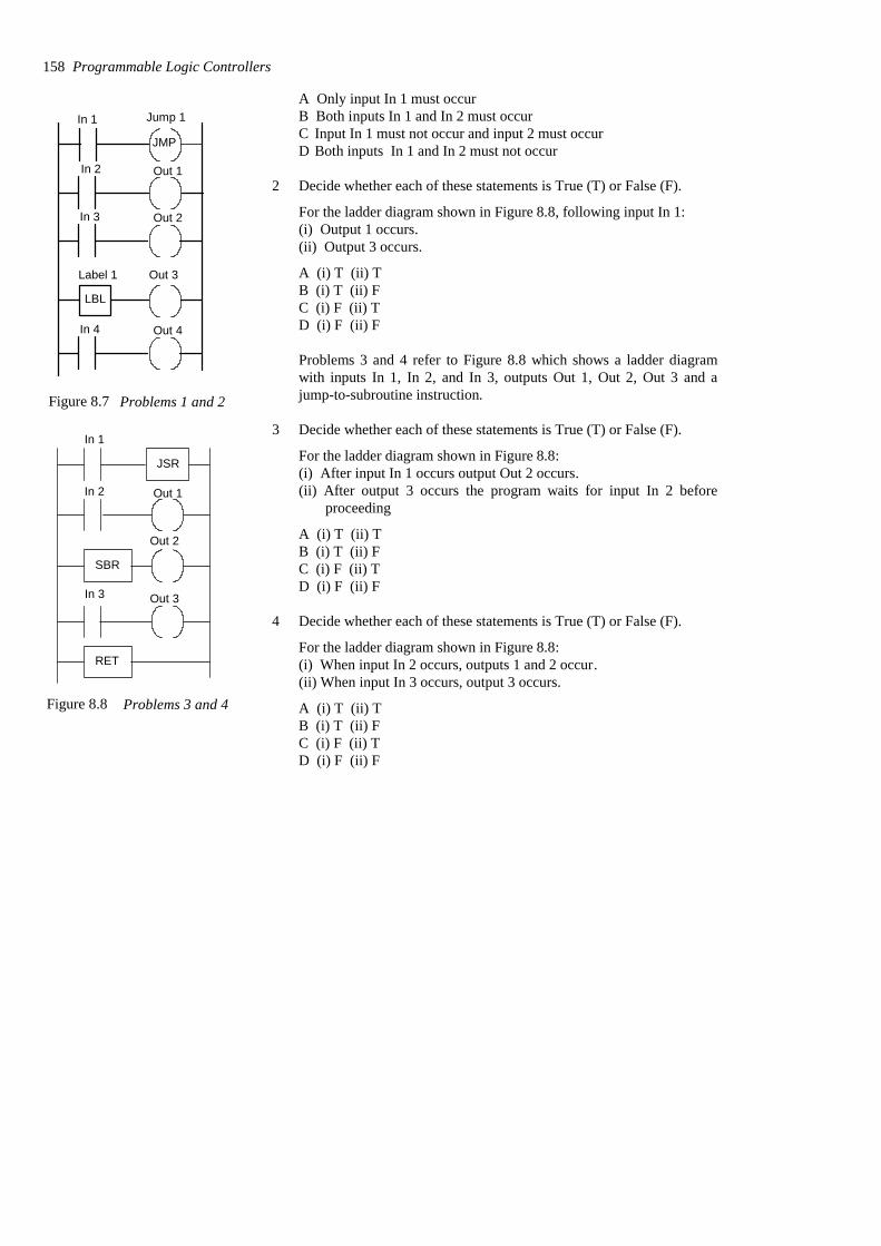
A Only input In 1 must occurB Both inputs In 1 and In 2 must occurC Input In 1 must not occur and input 2 must occurD Both inputs In 1 and In 2 must not occur
2 Decide whether each of these statements is True (T) or False (F).
For the ladder diagram shown in Figure 8.8, following input In 1:(i) Output 1 occurs.(ii) Output 3 occurs.
A (i) T (ii) TB (i) T (ii) FC (i) F (ii) TD (i) F (ii) F
Problems 3 and 4 refer to Figure 8.8 which shows a ladder diagramwith inputs In 1, In 2, and In 3, outputs Out 1, Out 2, Out 3 and ajump-to-subroutine instruction.
3 Decide whether each of these statements is True (T) or False (F).
For the ladder diagram shown in Figure 8.8:(i) After input In 1 occurs output Out 2 occurs.(ii) After output 3 occurs the program waits for input In 2 before
proceeding
A (i) T (ii) TB (i) T (ii) FC (i) F (ii) TD (i) F (ii) F
4 Decide whether each of these statements is True (T) or False (F).
For the ladder diagram shown in Figure 8.8:(i) When input In 2 occurs, outputs 1 and 2 occur.(ii) When input In 3 occurs, output 3 occurs.
A (i) T (ii) TB (i) T (ii) FC (i) F (ii) TD (i) F (ii) F
158 Programmable Logic Controllers
JMP
LBL
In 1 Jump 1
Label 1 Out 3
In 2
In 3
Out 1
Out 2
In 4 Out 4
Figure 8.7 Problems 1 and 2
JSR
SBR
RET
In 1
In 2
In 3
Out 1
Out 2
Out 3
Figure 8.8 Problems 3 and 4

9 Timers
In many control tasks there is a need to control time. For example, amotor or a pump might need to be controlled to operate for a particularinterval of time, or perhaps be switched on after some time interval. PLCsthus have timers as built-in devices. Timers count fractions of seconds orseconds using the internal CPU clock. This chapter shows how suchtimers can be programmed to carry out control tasks.
9.1 Types of timers PLC manufacturers differ on how timers should be programmed andhence how they can be considered. A common approach is to considertimers to behave like relays with coils which when energised result in theclosure or opening of contacts after some preset time. The timer is thustreated as an output for a rung with control being exercised over pairs ofcontacts elsewhere (Figure 9.1(a)). This is the predominant approach usedin this book. Some treat a timer as a delay block which when inserted in arung delays signals in that rung reaching the output (Figure 9.1(b)).
There are a number of different forms of timers that can be found withPLCs. With small PLCs there is likely to be just one form, the on-delaytimers. These are timers which come on after a particular time delay(Figure 9.2(a)). Off-delay timers are on for a fixed period of time beforeturning off (Figure 9.2(b)). Another type of timer that occurs is the pulsetimer. This timer switches on or off for a fixed period of time (Figure9.2(c)). Figure 9.3 shows the IEC 1131-3 standard symbols for timers.TON is used to denote on-delay, TOF off-delay. TP pulse timers.On-delay is also represented by T−0 and off-delay by 0−T.
Input
Timer
(a) On-delay timer
Input
Timer
(a) Off-delay timer
Input
Timer
(c) Pulse timer
output output output
Figure 9.2 Timers: (a) on-delay, (b) off-delay, (c) pulse
TONBOOL
TIME
BOOL
TIME
IN
PT
Q
ET
On-delay timer
TOFBOOL
TIME
BOOL
TIME
IN
PT
Q
ET
Off-delay timer
TPBOOL
TIME
BOOL
TIME
IN
PT
Q
ET
Pulse timer
Figure 9.3 IEC 1131-1 standards. BOOL indicates a Boolean input/output, i.e. on/off. IN is the input. Q is theoutput. ET is the elapsed time output. PT is the input used to specify the time.
(a)
Timer coil
Timer contacts
Time delaybefore activated
Timer
Time delay before inputsignal reaches output(b)
Figure 9.1 Treatment of timers
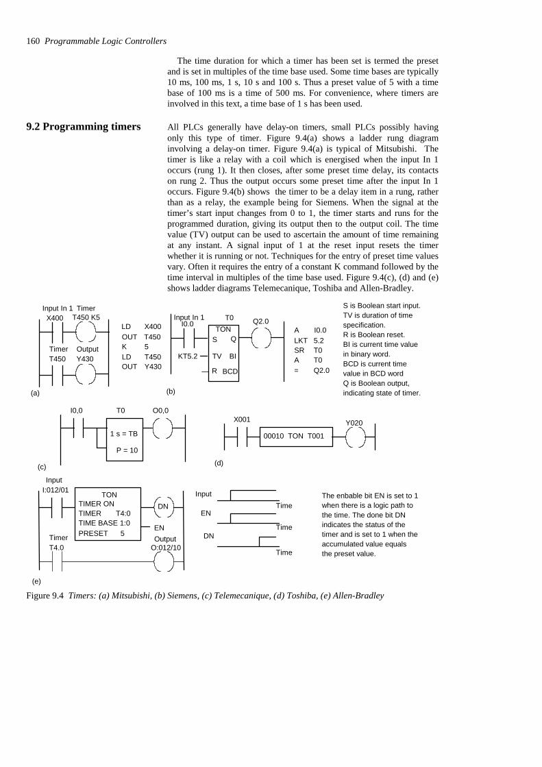
The time duration for which a timer has been set is termed the presetand is set in multiples of the time base used. Some time bases are typically10 ms, 100 ms, 1 s, 10 s and 100 s. Thus a preset value of 5 with a timebase of 100 ms is a time of 500 ms. For convenience, where timers areinvolved in this text, a time base of 1 s has been used.
9.2 Programming timers All PLCs generally have delay-on timers, small PLCs possibly havingonly this type of timer. Figure 9.4(a) shows a ladder rung diagraminvolving a delay-on timer. Figure 9.4(a) is typical of Mitsubishi. Thetimer is like a relay with a coil which is energised when the input In 1occurs (rung 1). It then closes, after some preset time delay, its contactson rung 2. Thus the output occurs some preset time after the input In 1occurs. Figure 9.4(b) shows the timer to be a delay item in a rung, ratherthan as a relay, the example being for Siemens. When the signal at thetimer’s start input changes from 0 to 1, the timer starts and runs for theprogrammed duration, giving its output then to the output coil. The timevalue (TV) output can be used to ascertain the amount of time remainingat any instant. A signal input of 1 at the reset input resets the timerwhether it is running or not. Techniques for the entry of preset time valuesvary. Often it requires the entry of a constant K command followed by thetime interval in multiples of the time base used. Figure 9.4(c), (d) and (e)shows ladder diagrams Telemecanique, Toshiba and Allen-Bradley.
X400 T450 K5
T450 Y430
LDOUT T450
X400
K 5LD T450OUT Y430
(a) (b)
T0I0.0 Q2.0
KT5.2
ALKTSRA=
I0.05.2T0T0Q2.0
TONS Q
TV
R
BI
BCD
Input In 1 Timer
Timer Output
Input In 1S is Boolean start input.TV is duration of timespecification.R is Boolean reset.BI is current time valuein binary word.BCD is current timevalue in BCD wordQ is Boolean output,indicating state of timer.
I0,0 T0
1 s = TB
P = 10
O0,0
00010 TON T001
X001 Y020
(c) (d)
TONI:012/01
TIMER ONTIMER T4:0TIME BASE 1:0PRESET 5
(e)
DN
EN
Input
EN
DN
Time
Time
Time
T4.0Timer
Input
O:012/10Output
The enbable bit EN is set to 1when there is a logic path tothe time. The done bit DNindicates the status of thetimer and is set to 1 when theaccumulated value equalsthe preset value.
Figure 9.4 Timers: (a) Mitsubishi, (b) Siemens, (c) Telemecanique, (d) Toshiba, (e) Allen-Bradley
160 Programmable Logic Controllers
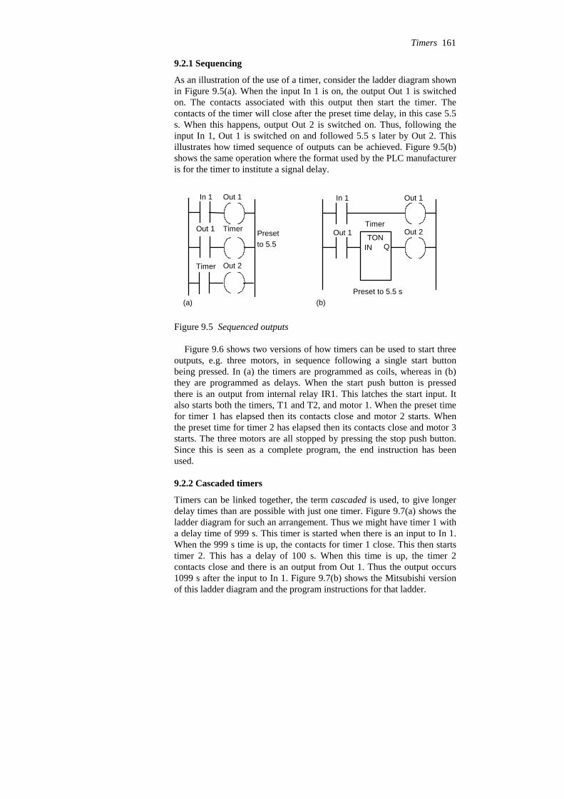
9.2.1 Sequencing
As an illustration of the use of a timer, consider the ladder diagram shownin Figure 9.5(a). When the input In 1 is on, the output Out 1 is switchedon. The contacts associated with this output then start the timer. Thecontacts of the timer will close after the preset time delay, in this case 5.5s. When this happens, output Out 2 is switched on. Thus, following theinput In 1, Out 1 is switched on and followed 5.5 s later by Out 2. Thisillustrates how timed sequence of outputs can be achieved. Figure 9.5(b)shows the same operation where the format used by the PLC manufactureris for the timer to institute a signal delay.
In 1 Out 1
Out 1 Timer
Timer Out 2
Presetto 5.5
In 1 Out 1
Out 1 TONOut 2
Timer
Preset to 5.5 s
IN Q
(a) (b)
Figure 9.5 Sequenced outputs
Figure 9.6 shows two versions of how timers can be used to start threeoutputs, e.g. three motors, in sequence following a single start buttonbeing pressed. In (a) the timers are programmed as coils, whereas in (b)they are programmed as delays. When the start push button is pressedthere is an output from internal relay IR1. This latches the start input. Italso starts both the timers, T1 and T2, and motor 1. When the preset timefor timer 1 has elapsed then its contacts close and motor 2 starts. Whenthe preset time for timer 2 has elapsed then its contacts close and motor 3starts. The three motors are all stopped by pressing the stop push button.Since this is seen as a complete program, the end instruction has beenused.
9.2.2 Cascaded timers
Timers can be linked together, the term cascaded is used, to give longerdelay times than are possible with just one timer. Figure 9.7(a) shows theladder diagram for such an arrangement. Thus we might have timer 1 witha delay time of 999 s. This timer is started when there is an input to In 1.When the 999 s time is up, the contacts for timer 1 close. This then startstimer 2. This has a delay of 100 s. When this time is up, the timer 2contacts close and there is an output from Out 1. Thus the output occurs1099 s after the input to In 1. Figure 9.7(b) shows the Mitsubishi versionof this ladder diagram and the program instructions for that ladder.
Timers 161

END
TON
TON
Motor 1
Motor 2
Motor 3
T1
T2
IR2
IR3
Start Stop IR1
IR1
IR1
IR1
IR1
IR2
IR3
END
Motor 1
Motor 2
Motor 3
Start Stop IR1
IR1
IR1
IR1
IR1
T1
T2
T1
T2
(a) (b)
Start
T1
T2
Motor 1
Motor 2
Motor 3
Stop
Timing diagram
IN Q
IN Q
Figure 9.6 Motor sequence
In 1 Timer 1
Timer 2
Timer 2 Out 1
Preset999
Preset 100
T450 K999
Timer 1
X400
T450 T451 K100
T451 Y430
LDOUTKLDOUTKLDOUT
X400T450999T450T451100T451Y430
(a) (b)
Figure 9.7 Cascaded timers
9.2.3 On-off cycle timer
Figure 9.8 shows how on-delay timers can be used to produce an on-offcycle timer. The timer is designed to switch on an output for 5 s, then offfor 5 s, then on for 5 s, then off for 5 s, and so on. When there is an inputto In 1 and its contacts close, timer 1 starts. Timer 1 is set for a delay of 5s. After 5 s, it switches on timer 2 and the output Out 1. Timer 2 has adelay of 5 s. After 5 s, the contacts for timer 2, which are normally closed,
162 Programmable Logic Controllers
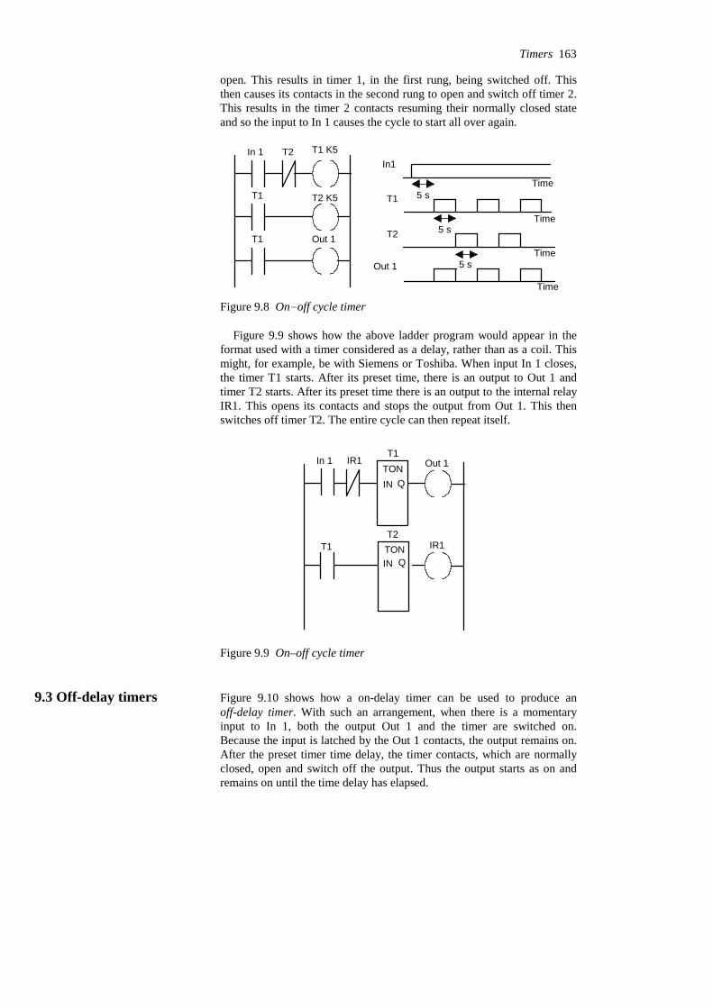
open. This results in timer 1, in the first rung, being switched off. Thisthen causes its contacts in the second rung to open and switch off timer 2.This results in the timer 2 contacts resuming their normally closed stateand so the input to In 1 causes the cycle to start all over again.
In 1 T2 T1 K5
T1
T1
T2 K5
Out 1
In1
T1
T2
Out 1
5 s
5 s
5 s
Time
Time
Time
Time
Figure 9.8 On-off cycle timer
Figure 9.9 shows how the above ladder program would appear in theformat used with a timer considered as a delay, rather than as a coil. Thismight, for example, be with Siemens or Toshiba. When input In 1 closes,the timer T1 starts. After its preset time, there is an output to Out 1 andtimer T2 starts. After its preset time there is an output to the internal relayIR1. This opens its contacts and stops the output from Out 1. This thenswitches off timer T2. The entire cycle can then repeat itself.
In 1
T1
IR1T1
Out 1
T2IR1
TON
TON
IN Q
IN Q
Figure 9.9 On–off cycle timer
9.3 Off-delay timers Figure 9.10 shows how a on-delay timer can be used to produce anoff-delay timer. With such an arrangement, when there is a momentaryinput to In 1, both the output Out 1 and the timer are switched on.Because the input is latched by the Out 1 contacts, the output remains on.After the preset timer time delay, the timer contacts, which are normallyclosed, open and switch off the output. Thus the output starts as on andremains on until the time delay has elapsed.
Timers 163
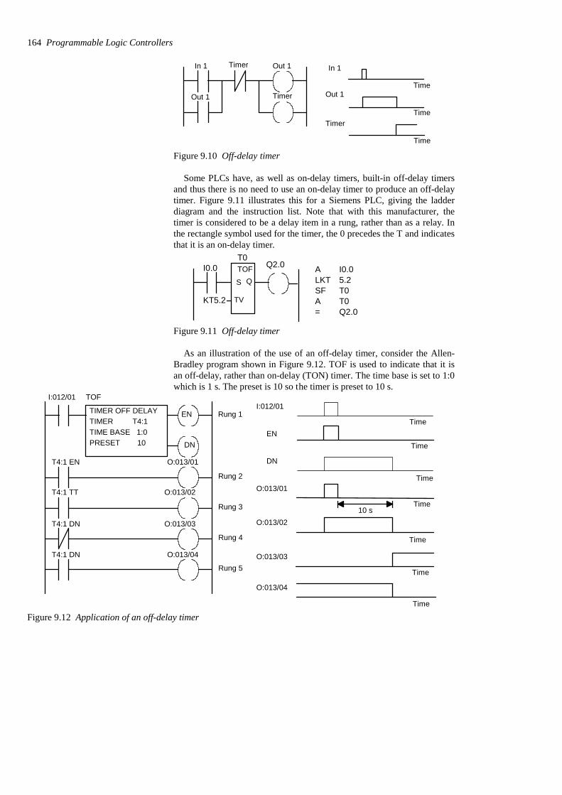
In 1 Timer Out 1
TimerOut 1
In 1
Out 1
Timer
Time
Time
Time
Figure 9.10 Off-delay timer
Some PLCs have, as well as on-delay timers, built-in off-delay timersand thus there is no need to use an on-delay timer to produce an off-delaytimer. Figure 9.11 illustrates this for a Siemens PLC, giving the ladderdiagram and the instruction list. Note that with this manufacturer, thetimer is considered to be a delay item in a rung, rather than as a relay. Inthe rectangle symbol used for the timer, the 0 precedes the T and indicatesthat it is an on-delay timer.
I0.0T0
Q2.0
KT5.2
ALKTSFA=
I0.05.2T0T0Q2.0
TOF
S Q
TV
Figure 9.11 Off-delay timer
As an illustration of the use of an off-delay timer, consider the Allen-Bradley program shown in Figure 9.12. TOF is used to indicate that it isan off-delay, rather than on-delay (TON) timer. The time base is set to 1:0which is 1 s. The preset is 10 so the timer is preset to 10 s.
TOF
TIMER OFF DELAYTIMER T4:1TIME BASE 1:0PRESET 10
EN
DN
T4:1 EN
T4:1 TT
T4:1 DN
T4:1 DN
I:012/01
O:013/01
O:013/02
O:013/03
O:013/04
Rung 1
Rung 2
Rung 3
Rung 4
Rung 5
I:012/01
O:013/01
O:013/02
O:013/03
O:013/04
Time
Time
Time
Time
10 s
TimeEN
DN
Time
Time
Figure 9.12 Application of an off-delay timer
164 Programmable Logic Controllers

In the first rung, the output of the timer is taken from the EN (forenable) contacts. This means that there is no time delay between an inputto I:012/01 and the EN output. As a result the EN contacts in rung 2 closeimmediately there is an I:012/01 input. Thus there is an output fromO:013/01 immediately the input I:012/01 occurs. The TT (for timertiming) contacts in rung 3 are energised just while the timer is running.Because the timer is an off-delay timer, the timer is turned on for 10 sbefore turning off. Thus the TT contacts will close when the set time of10 s is running. Hence output O:012/02 is switched on for this time of10 s. The DN (for done) contacts which are normally closed, open afterthe 10 s and so output O:013/03 comes on after 10 s. The DN contactswhich are normally open, close after 10 s and so output O:013/04 goes offafter 10 s.
9.4 Pulse timers Pulse timers are used to produce a fixed duration output from someinitiating input. Figure 9.13(a) shows a ladder diagram for a system thatwill give an output from Out 1 for a predetermined fixed length of timewhen there is an input to In 1, the timer being one involving a coil. Thereare two outputs for the input In 1. When there is an input to In 1, there isan output from Out 1 and the timer starts. When the predetermined timehas elapsed, the timer contacts open. This switches off the output. Thusthe output remains on for just the time specified by the timer.
In 1 Timer
Timer Out 1
In 1
Timercontacts
ClosedOpen
Out 1
Time
Time
Time(a)
(b)
In 1
TON
TimerInternalrelay
Internalrelay Out 1
Figure 9.13 Pulse-on timer
Figure 9.13(b) shows an equivalent ladder diagram to Figure 9.13(a)but employing a timer which produces a delay in the time taken for asignal to reach the output.
In Figure 9.13, the pulse timer has an output switched on by an inputfor a predetermined time, then switching off. Figure 9.14 shows anotherpulse timer that switches an output on for a predetermined time after theinput ceases. This uses a timer and two internal relays. When there is an
Timers 165

input to In 1, the internal relay IR 1 is energised. The timer does not startat this point because the normally closed In 1 contacts are open. Theclosing of the IR 1 contacts means that the internal relay IR 2 is energised.There is, however, no output from Out 1 at this stage because, for thebottom rung, we have In 1 contacts open. When the input to In 1 ceases,both the internal relays remain energised and the timer is started. After theset time, the timer contacts, which are normally closed, open and switchoff IR 2. This in turn switches off IR 1. It also, in the bottom rung,switches off the output Out 1. Thus the output is off for the duration of theinput, then being switched on for a predetermined length of time.
In 1 In 1 Timer
IR 2 IR 1
IR 1 Timer IR 2
In 1 IR 2 Out 1
In 1
IR 1
IR 2
Out 1
Timer
Time
Time
Time
Time
Time
Figure 9.14 Pulse timer on, when output ceases
9.5 Programming examples Consider a program (Figure 9.15) that could be used to flash a light onand off as long as there is some output occurring. Thus we might haveboth timer 0 and timer 1 set to 1 s. When the output occurs, then timer 0starts and switches on after 1 s. This closes the timer 0 contacts and startstimer 1. This switches on after 1 s and, in doing so, switches off timer 0.In so doing, it switches off itself. The lamp is only on when timer 0 is onand so we have a program to flash the lamp on and off as long as there isan output.
Timer 1TON
Timer 1
Timer 0
Timer 0TON
LampTimer 0
Output
END
Figure 9.15 Flashing light
166 Programmable Logic Controllers

As an illustration of programming involving timers consider thesequencing of traffic lights to give the sequence red only, red plus amber,green, amber, then repeat itself. A simple system might just have thesequence triggered by time, with each of the possible states occurring insequence for a fixed amount of time. Figure 9.16 shows the sequentialfunction chart and a possible ladder program to give the sequence.
State 0 Red only
State 1 Red + amber
State 2 Green only
State 3 Amber only
Time 2 min
Time 20 s
Time 2 min
Time 20 s
Start
Start Red
Red
RedTON
Timer 1
2 min
Red
Amber
AmberTON
Timer 2
20 s
Green
GreenTON
Timer 3
2 min
AmberState 3
State 2
State 1
State 0
END
RedAmberTON
Timer 3
20 s
Start
End
IN Q
IN Q
IN Q
IN Q
Figure 9.16 Traffic light sequence
Problems Questions 1 to 19 have four answer options: A, B, C or D. Choose thecorrect answer from the answer options.
Problems 1 to 3 refer to Figure 9.17 which shows a ladder diagramwith an on-delay timer, an input In 1 and an output Out 1.
1 Decide whether each of these statements is True (T) or False (F).
When there is an input to In 1 in Figure 9.17:(i) The timer starts.(ii) There is an output from Out 1.
A (i) T (ii) TB (i) T (ii) FC (i) F (ii) TD (i) F (ii) F
Timers 167

2 Decide whether each of these statements is True (T) or False (F).
The timer in Figure 9.17 starts when:(i) There is an output.(ii) The input ceases.
A (i) T (ii) TB (i) T (ii) FC (i) F (ii) TD (i) F (ii) F
3 Decide whether each of these statements is True (T) or False (F).
When there is an input to In 1, the output is switched:(i) On for the time for which the timer was preset.(ii) Off for the time for which the timer was preset.
A (i) T (ii) TB (i) T (ii) FC (i) F (ii) TD (i) F (ii) F
Problems 4 to 6 refer to Figure 9.18 which shows two alternativeversions of a ladder diagram with two inputs In 1 and In 2, twooutputs Out 1 and Out 2 and an on-delay timer.
In 1 In 2 Out 1
Out 1 Timer
Timer Out 2
In 1 In 2 Out 1
Timer
TON
Out 2
Figure 9.18 Problems 4 to 6
4 Decide whether each of these statements is True (T) or False (F).
When there is just an input to In 1:(i) The timer starts.(ii) There is an output from Out 2.
A (i) T (ii) TB (i) T (ii) FC (i) F (ii) TD (i) F (ii) F
5 Decide whether each of these statements is True (T) or False (F).
When there is just an input to In 2:(i) The timer starts.(ii) There is an output from Out 2.
168 Programmable Logic Controllers
In 1 Timer
In 1 Timer Out 1
Out 1
Figure 9.17 Problems 1 to 3
A (i) T (ii) TB (i) T (ii) FC (i) F (ii) TD (i) F (ii) F
6 Decide whether each of these statements is True (T) or False (F).
When there is an input to In 1 and no input to In 2, there is an outputfrom Out 2 which:(i) Starts immediately.(ii) Ceases after the timer preset time.
A (i) T (ii) TB (i) T (ii) FC (i) F (ii) TD (i) F (ii) F
7 The program instruction list for a Mitsubishi PLC is: LD X400, OUTT450, K 6, LD T450, OUT Y430. An input to X400 gives:
A An output which is on for 6 s then off for 6 s.B An output which lasts for 6 s.C An output which starts after 6 s.D An output which is off for 6 s, then on for 6 s.
8 The program instruction list for a Telemecanique PLC is: L I0,0, =T0, L T0, = O0,0. When there is an input to I0,0 there is:
A An output which is on for 6 s then off for 6 s.B An output which lasts for 6 s.C An output which starts after 6 s.D An output which is off for 6 s, then on for 6 s.
Problems 9 and 10 refer to the program instruction list for aMitsubishi PLC: LD X400, OR Y430, ANI T450, OUT Y430, LDX401, OR M100, AND Y430, OUT T450, K 10, OUT M100.
9 Decide whether each of these statements is True (T) or False (F).
When there is a momentary input to X400:(i) The output from Y430 starts.(ii) The output from Y430 ceases after 10 s.
A (i) T (ii) TB (i) T (ii) FC (i) F (ii) TD (i) F (ii) F
10 Decide whether each of these statements is True (T) or False (F).
The output from Y430:(i) Starts when there is a momentary input to X401.(ii) Ceases 10 s after the input to X401.
Timers 169

A (i) T (ii) TB (i) T (ii) FC (i) F (ii) TD (i) F (ii) F
Problems 11 and 12 refer to Figure 9.19 which shows a system withan input In 1, an on-delay timer and an output Out 1. The timer is setfor a time of 6 s. The graph shows how the signal to the input varieswith time.
In 1 Timer
Timer Out 1
In 1
Time
Figure 9.19 Problems 11 and 12
11 Decide whether each of these statements is True (T) or False (F).
The output from Out 1:(i) Starts when the input starts.(ii) Ceases 6 s after the start of the input.
A (i) T (ii) TB (i) T (ii) FC (i) F (ii) TD (i) F (ii) F
12 Decide whether each of these statements is True (T) or False (F).
The timer contacts:(i) Remain closed for 6 s after the start of the input.(ii) Open 6 s after the input starts.
A (i) T (ii) TB (i) T (ii) FC (i) F (ii) TD (i) F (ii) F
Problems 13 to 15 refer to Figure 9.20 which shows a ladder programfor a Toshiba PLC involving internal relays, denoted by the letter R,and a TON timer with a preset of 20 s.
13 Decide whether each of these statements is True (T) or False (F).
The internal relay R000 in Figure 9.20:(i) Is used to latch the input X001.(ii) Is used to start the timer T001.
A (i) T (ii) TB (i) T (ii) FC (i) F (ii) TD (i) F (ii) F
170 Programmable Logic Controllers

TON T001
X001 X002 R000
R000
R000 Y020
R001
R001 Y021
Figure 9.20 Problems 13 to 15
14 Decide whether each of these statements is True (T) or False (F).
With no input to X002 in Figure 9.20, the output Y020 is:(i) Energised when there is an input to X001.(ii) Ceases when there is no input to X001.
A (i) T (ii) TB (i) T (ii) FC (i) F (ii) TD (i) F (ii) F
15 Decide whether each of these statements is True (T) or False (F).
With no input to X002 in Figure 9.20:(i) The output Y021 is switched on 20 s after the input X001.(ii) The output Y020 is switched off 20 s after the input X001.
A (i) T (ii) TB (i) T (ii) FC (i) F (ii) TD (i) F (ii) F
Problems 16 to 19 refer to Figure 9.21 which shows an Allen-Bradleyprogram and Figure 9.22 which shows a number of time charts for aparticular signal input to I:012/01.
16 For the input shown in Figure 9.22, which is the output fromO:013/01?
17 For the input shown in Figure 9.22, which is the output fromO:013/02?
18 For the input shown in Figure 9.22, which is the output fromO:013/03?
Timers 171

TON
TIMER ON DELAYTIMER T4:1TIME BASE 1:0PRESET 50
EN
DN
I:012/01
T4:1 EN
T4:1 TT
T4:1 DN
T4:1 DN
O:013/01
O:013/02
O:013/03
O:013/04
Input
A
B
C
D
Time
Time
Time
Time
Time
50 s
Figure 9.21 Problems 16 to 19 Figure 9.22 Problems 16 to 19
19 For the input shown in Figure 9.22, which is the output fromO:013/04?
20 Devise ladder programs for systems that will carry out the followingtasks:(a) Switch on an output 5 s after receiving an input and keep it on forthe duration of that input.(b) Switch on an output for the duration of the input and then keep iton for a further 5 s.(c) Switch on an output for 5 s after the start of an input signal.
172 Programmable Logic Controllers

10 Counters
Counters are provided as built-in elements in PLCs and allow the numberof occurrences of input signals to be counted. This might be where itemshave to be counted as they pass along a conveyor belt, or the the numberof revolutions of a shaft, or perhaps the number of people passing througha door. This chapter describes how such counters can be programmed.
10.1 Forms of counter A counter is set to some preset number value and, when this value of inputpulses has been received, it will operate its contacts. Thus normally opencontacts would be closed, normally closed contacts opened.
There are two types of counter, though PLCs may not include bothtypes. These are down-counters and up-counters. Down-counters countdown from the preset value to zero, i.e. events are subtracted from the setvalue. When the counter reaches the zero value, its contacts change state.Most PLCs offer down counting. Up-counters count from zero up to thepreset value, i.e. events are added until the number reaches the presetvalue. When the counter reaches the set value, its contacts change state.
Different PLC manufacturers deal with counters in slightly differentways. Some count down (CTD), or up (CTU), and reset and treat thecounter as though it is a relay coil and so a rung output. In this way,counters can be considered to consist of two basic elements: one relay coilto count input pulses and one to reset the counter, the associated contactsof the counter being used in other rungs. Figure 10.1(a) illustrates this.Mitsubishi is an example of this type of manufacturer. Others treat thecounter as an intermediate block in a rung from which signals emanatewhen the count is attained. Figure 10.1(b) illustrates this. Siemens is anexample of this type of manufacturer.
Counter
Counter
RST
CTD
Counter
Activated whenzero reached after counting
R
CU
PV
Output when set countreached after counting
Counter
Q
CV
CTU
PV
CD
LD
Output when zero reachedafter counting down
Counter
Q
CV
CTD
Counter
Counter
RST
CTU
Counter
Activated whenset count reached after
down from set value counting up from zero from set value up from zero(a) (b)
Figure 10.1 Forms of representation of counters. In (a) RST is reset. In (b), the IEC 1131-3 representation, CDis count down input, LD is for loading the input, PV is for the preset value, CV the current count value, CU iscount up input, and R is for the reset input.
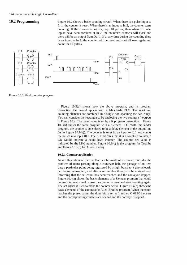
10.2 Programming Figure 10.2 shows a basic counting circuit. When there is a pulse input toIn 1, the counter is reset. When there is an input to In 2, the counter startscounting. If the counter is set for, say, 10 pulses, then when 10 pulseinputs have been received at In 2, the counter’s contacts will close andthere will be an output from Out 1. If at any time during the counting thereis an input to In 1, the counter will be reset and start all over again andcount for 10 pulses.
In 1 Counter
RST
CounterIn 2
Counter Out 1
In 1
In 2
Out 1
Time
Time
Time
Counter
CUCTU
Q
R
PV
CVIn 1
In 2 Out 1
CU
Figure 10.2 Basic counter program
Figure 10.3(a) shows how the above program, and its programinstruction list, would appear with a Mitsubishi PLC. The reset andcounting elements are combined in a single box spanning the two rungs.You can consider the rectangle to be enclosing the two counter ( ) outputsin Figure 10.2. The count value is set by a K program instruction. Figure10.3(b) shows the same program with a Siemens PLC. With this ladderprogram, the counter is considered to be a delay element in the output line(as in Figure 10.1(b)). The counter is reset by an input to I0.1 and countsthe pulses into input I0.0. The CU indicates that it is a count-up counter, aCD would indicate a count-down counter. The counter set value isindicated by the LKC number. Figure 10.3(c) is the program for Toshibaand Figure 10.3(d) for Allen-Bradley.
10.2.1 Counter application
As an illustration of the use that can be made of a counter, consider theproblem of items passing along a conveyor belt, the passage of an itempast a particular point being registered by a light beam to a photoelectriccell being interrupted, and after a set number there is to be a signal sentinforming that the set count has been reached and the conveyor stopped.Figure 10.4(a) shows the basic elements of a Siemens program that couldbe used. A reset signal causes the counter to reset and start counting again.The set signal is used to make the counter active. Figure 10.4(b) shows thebasic elements of the comparable Allen-Bradley program. When the countreaches the preset value, the done bit is set to 1 and so O:013/01 occursand the corresponding contacts are opened and the conveyor stopped.
174 Programmable Logic Controllers
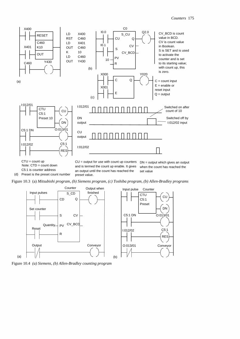
X400
X401
C460
RESET
OUT
C460K10
Y430
LDRSTLDOUTKLDOUT
X400C460X401C46010C460Y430
(a)
(b)
C0
CU
PV
I0.0
I0.1
Q2.0
R
QS_CU
10
SCV
CV_BCD
C
E
Q C = count inputE = enable or
Q = output
X000
X001
Y020
(c)
CTU = count up
C5:1 is counter addressPreset is the preset count number
Note: CTD = count downCU = output for use with count up countersand is termed the count up enable. It givesan output until the count has reached the preset value.
DN = output which gives an outputwhen the count has reached the
CTUC5:1Preset 10
O:013/01
I:012/01
C5:1 DN
I:012/02 C5:1
RES
DN
CUI:012/01
DNoutput
CUoutput
I:012/02
Switched on aftercount of 10
Switched off byI:012/02 input
(d)set value
CV_BCD is countvalue in BCD.CV is count valuein Boolean.S is SET and is usedto activate thecounter and is setto its starting value;with count up, thisis zero.
reset input
Figure 10.3 (a) Mitsubishi program, (b) Siemens program, (c) Toshiba program, (b) Allen-Bradley programsCounter
S_CD
CD Q
S
PV
R
CV
CV_BCD
Set counter
Quantity
Input pulses Output when
finished
Output Conveyor
Reset
CTUC5:1Preset
O:013/01C5:1 DN
I:012/02 C5:1
RES
DN
CU
(a) (b)
Input pulse Counter
O:013/01 Conveyor
Figure 10.4 (a) Siemens, (b) Allen-Bradley counting program
Counters 175
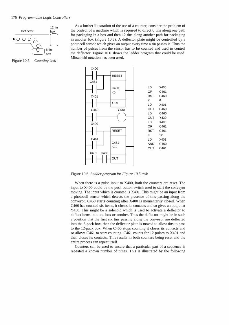
As a further illustration of the use of a counter, consider the problem ofthe control of a machine which is required to direct 6 tins along one pathfor packaging in a box and then 12 tins along another path for packagingin another box (Figure 10.5). A deflector plate might be controlled by aphotocell sensor which gives an output every time a tin passes it. Thus thenumber of pulses from the sensor has to be counted and used to controlthe deflector. Figure 10.6 shows the ladder program that could be used.Mitsubishi notation has been used.
C460K6
RESET
X400
C461
X401
OUT
RESET
C461K12
OUT
C460 Y430
X400
C461
X401 C460
LDORRSTKLDOUTLDOUTLDORRSTKLDANDOUT
X400C461C4606X401C460C460Y430X400C461C46112X401C460C461
Figure 10.6 Ladder program for Figure 10.5 task
When there is a pulse input to X400, both the counters are reset. Theinput to X400 could be the push button switch used to start the conveyormoving. The input which is counted is X401. This might be an input froma photocell sensor which detects the presence of tins passing along theconveyor. C460 starts counting after X400 is momentarily closed. WhenC460 has counted six items, it closes its contacts and so gives an output atY430. This might be a solenoid which is used to activate a deflector todeflect items into one box or another. Thus the deflector might be in sucha position that the first six tins passing along the conveyor are deflectedinto the 6-pack box, then the deflector plate is moved to allow tins to passto the 12-pack box. When C460 stops counting it closes its contacts andso allows C461 to start counting. C461 counts for 12 pulses to X401 andthen closes its contacts. This results in both counters being reset and theentire process can repeat itself.
Counters can be used to ensure that a particular part of a sequence isrepeated a known number of times. This is illustrated by the following
176 Programmable Logic Controllers
Deflector12 tinbox
6 tinbox
Figure 10.5 Counting task

program which is designed to enable a three-cylinder, double solenoid-controlled arrangement (Figure 10.7(a)) to give the sequence A+, A–, A+,A–, A+, A–, B+, C+, B–, C–. The A+, A– sequence is repeated threetimes before B+, C+, B–, C– occur. We can use a counter to enable thisrepetition. Figure 10.7(b) shows a possible program. The counter onlyallows B+ to occur after it has received three inputs corresponding tothree a– signals.
B
b– b+
B+ B–
A
a– a+
A+ A–
PLC
a–
a+
b–
b+
c+
Inputs from
A+
A–
B+
B–
C+
C–
Outputs tosolenoidslimit switches
PowerE L N
StartStop
–V
C
c+
C+ C–
c–
RSTCounterK3
OUT
END
Start
Start
a– A+
a+ A–
a–
Counter B+
C+b+
c+ B–
C–b– c+
(a) (b)
Figure 10.7 (a) Three-cylinder system, (b) program
Counters 177
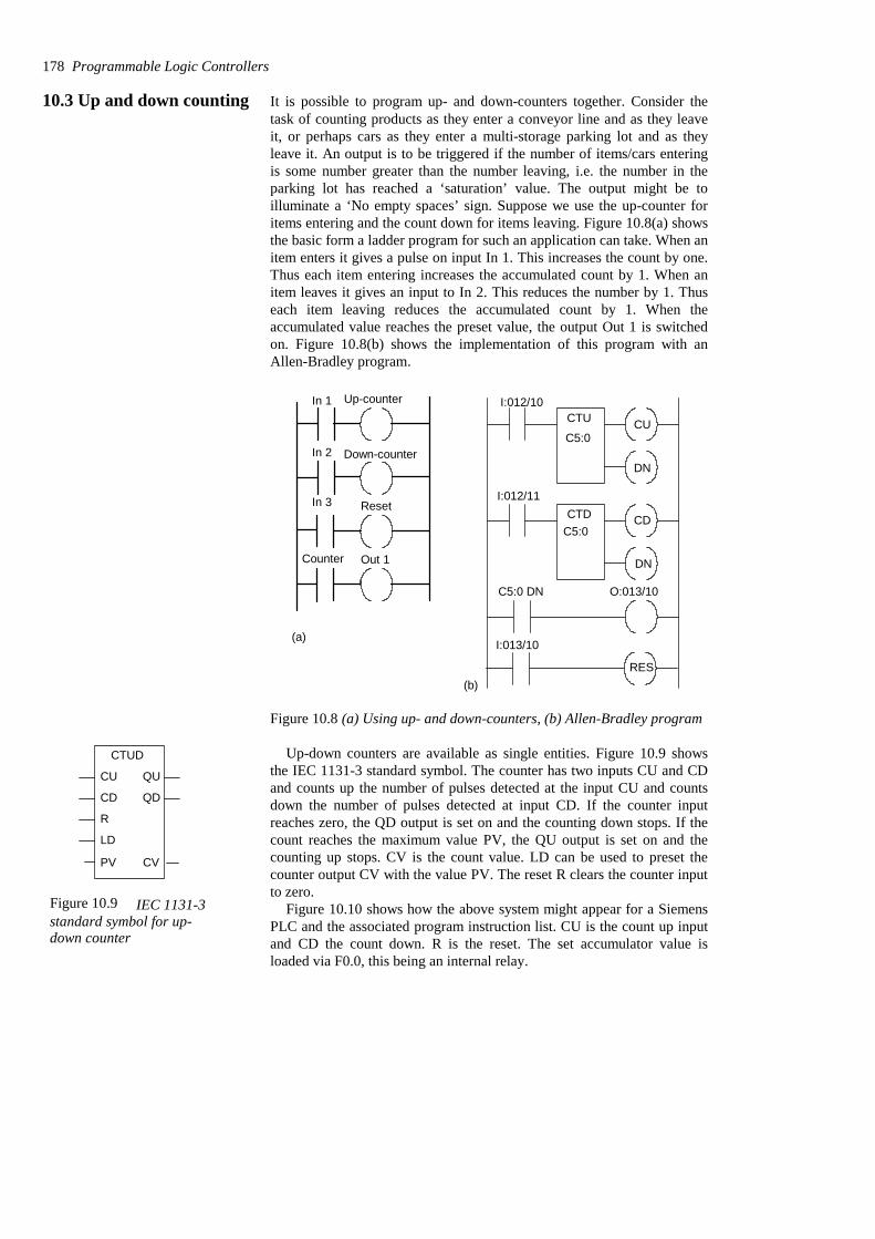
10.3 Up and down counting It is possible to program up- and down-counters together. Consider thetask of counting products as they enter a conveyor line and as they leaveit, or perhaps cars as they enter a multi-storage parking lot and as theyleave it. An output is to be triggered if the number of items/cars enteringis some number greater than the number leaving, i.e. the number in theparking lot has reached a ‘saturation’ value. The output might be toilluminate a ‘No empty spaces’ sign. Suppose we use the up-counter foritems entering and the count down for items leaving. Figure 10.8(a) showsthe basic form a ladder program for such an application can take. When anitem enters it gives a pulse on input In 1. This increases the count by one.Thus each item entering increases the accumulated count by 1. When anitem leaves it gives an input to In 2. This reduces the number by 1. Thuseach item leaving reduces the accumulated count by 1. When theaccumulated value reaches the preset value, the output Out 1 is switchedon. Figure 10.8(b) shows the implementation of this program with anAllen-Bradley program.
Up-counterIn 1
Down-counterIn 2
In 3 Reset
Out 1Counter
(a)
(b)
CTU
CTD
DN
CU
CD
DN
C5:0
C5:0
C5:0 DN
RES
I:012/10
I:012/11
I:013/10
O:013/10
Figure 10.8 (a) Using up- and down-counters, (b) Allen-Bradley program
Up-down counters are available as single entities. Figure 10.9 showsthe IEC 1131-3 standard symbol. The counter has two inputs CU and CDand counts up the number of pulses detected at the input CU and countsdown the number of pulses detected at input CD. If the counter inputreaches zero, the QD output is set on and the counting down stops. If thecount reaches the maximum value PV, the QU output is set on and thecounting up stops. CV is the count value. LD can be used to preset thecounter output CV with the value PV. The reset R clears the counter inputto zero.
Figure 10.10 shows how the above system might appear for a SiemensPLC and the associated program instruction list. CU is the count up inputand CD the count down. R is the reset. The set accumulator value isloaded via F0.0, this being an internal relay.
178 Programmable Logic Controllers
CTUD
QU
QD
CU
CD
R
LD
PV CV
Figure 10.9 IEC 1131-3standard symbol for up-down counter
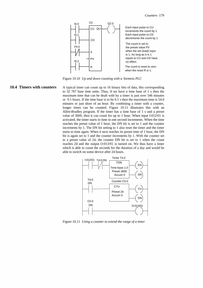
I0.0
I0.1
F0.0
I0.2
C0
CU
CD
S
PV
R
QU
Q2.0
The count is set tothe preset value PVwhen the set (load) inputis 1. As long as it is 1
Each input pulse to CUincrements the count by 1Each input pulse to CDdecrements the count by 1
The count is reset to zerowhen the reset R is 1.
inputs to CU and CD haveno effect.
Figure 10.10 Up and down counting with a Siemens PLC
10.4 Timers with counters A typical timer can count up to 16 binary bits of data, this correspondingto 32 767 base time units. Thus, if we have a time base of 1 s then themaximum time that can be dealt with by a timer is just over 546 minutesor 9.1 hours. If the time base is to be 0.1 s then the maximum time is 54.6minutes or just short of an hour. By combining a timer with a counter,longer times can be counted. Figure 10.11 illustrates this with anAllen-Bradley program. If the timer has a time base of 1 s and a presetvalue of 3600, then it can count for up to 1 hour. When input I:012/01 isactivated, the timer starts to time in one second increments. When the timereaches the preset value of 1 hour, the DN bit is set to 1 and the counterincrements by 1. The DN bit setting to 1 also reset the timer and the timerstarts to time again. When it next reaches its preset time of 1 hour, the DNbit is again set to 1 and the counter increments by 1. With the counter setto a preset value of 24, the counter DN bit is set to 1 when the countreaches 24 and the output O:013/01 is turned on. We thus have a timerwhich is able to count the seconds for the duration of a day and would beable to switch on some device after 24 hours.
EN
DN
T4:0 DNI:012/01
CU
DN
T4:0DN
C5.0DN O:013/01
Timer T4.0
Counter C5.0
TON
Time base 1.0Preset 3600
Accum 0
CTU
Preset 24Accum 0
Figure 10.11 Using a counter to extend the range of a timer
Counters 179
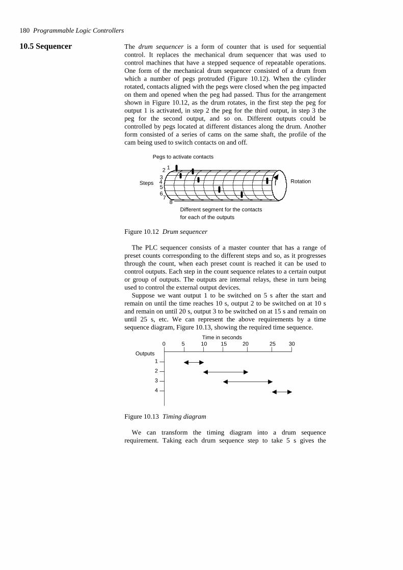
10.5 Sequencer The drum sequencer is a form of counter that is used for sequentialcontrol. It replaces the mechanical drum sequencer that was used tocontrol machines that have a stepped sequence of repeatable operations.One form of the mechanical drum sequencer consisted of a drum fromwhich a number of pegs protruded (Figure 10.12). When the cylinderrotated, contacts aligned with the pegs were closed when the peg impactedon them and opened when the peg had passed. Thus for the arrangementshown in Figure 10.12, as the drum rotates, in the first step the peg foroutput 1 is activated, in step 2 the peg for the third output, in step 3 thepeg for the second output, and so on. Different outputs could becontrolled by pegs located at different distances along the drum. Anotherform consisted of a series of cams on the same shaft, the profile of thecam being used to switch contacts on and off.
Rotation
Different segment for the contactsfor each of the outputs
Pegs to activate contacts
123456
78
Steps
Figure 10.12 Drum sequencer
The PLC sequencer consists of a master counter that has a range ofpreset counts corresponding to the different steps and so, as it progressesthrough the count, when each preset count is reached it can be used tocontrol outputs. Each step in the count sequence relates to a certain outputor group of outputs. The outputs are internal relays, these in turn beingused to control the external output devices.
Suppose we want output 1 to be switched on 5 s after the start andremain on until the time reaches 10 s, output 2 to be switched on at 10 sand remain on until 20 s, output 3 to be switched on at 15 s and remain onuntil 25 s, etc. We can represent the above requirements by a timesequence diagram, Figure 10.13, showing the required time sequence.
0 5 10 15 20 25 30
Outputs1
2
3
4
Time in seconds
Figure 10.13 Timing diagram
We can transform the timing diagram into a drum sequencerequirement. Taking each drum sequence step to take 5 s gives the
180 Programmable Logic Controllers

requirement diagram shown in Table 10.1. Thus at step 1 we requireoutput 1 to be switched on and to remain on until step 2. At step 2 werequire output 2 to be switched on and remain on until step 4. At step 3we require output 3 to be switched on and remain on until step 5. At step5 we require output 4 to be switched on and remain on until step 6.
Table 10.1 Sequence requirements
000030611002550100204011015300101020001 510000 00
Output 4Output 3Output 2Output 1Time (s)Step
With a PLC, such as a Toshiba, the sequencer is set up by switching onthe Step Sequence Initialize (STIZ) function block R500 (Figure 10.14).This sets up the program for step 1 and R501. This relay then switches onoutput Y020. The next step is the switching on of R502. This switches onthe output Y021 and also a delay-on timer so that R503 is not switched onuntil the timer has timed out. Then R503 switches on Y022 and also thenext step in the sequence.
X000 to switch on sequencer
STIZ R500
R500 R501
R501 R502
R501 Y020
R502
TON T000
R503
R503 Y022
R503 R504
and so on
R502 Y021
Figure 10.14 Sequencer with a Toshiba PLC
Counters 181

With the Allen-Bradley form of PLC the sequencer is programmed byusing a sequence of binary words in the form of the outputs required, e.g.those listed in Table 10.1. Thus we would have the following binary wordsequence put into the program using the programming device.
0000000100100110010001000000
Input 4 Input 3 Input 2 Input 1
Problems Questions 1 to 19 have four answer options: A, B, C or D. Choose thecorrect answer from the answer options.
Problems 1 to 3 refer to Figure 10.15 which shows a ladder diagramwith a counter, two inputs In 1 and In 2 and an output Out 1.
1 Decide whether each of these statements is True (T) or False (F).
For the ladder diagram shown in Figure 10.15, when the counter is setto 5, there is an output from Out 1 every time:(i) In 1 has closed 5 times.(ii) In 2 has closed 5 times.
A (i) T (ii) TB (i) T (ii) FC (i) F (ii) TD (i) F (ii) F
2 Decide whether each of these statements is True (T) or False (F).
For the ladder diagram shown in Figure 10.15:(i) The first rung gives the condition required to reset the counter.(ii) The second rung gives the condition required to generate pulsesto be counted.
A (i) T (ii) TB (i) T (ii) FC (i) F (ii) TD (i) F (ii) F
3 Decide whether each of these statements is True (T) or False (F).
In Figure 10.15, when there is an input to In 1:(i) The counter contacts in the third rung close.(ii) The counter is ready to start counting the pulses from In 2.
182 Programmable Logic Controllers
In 1 Counter
RST
CounterIn 2
Counter Out 1
First rung
Second rung
Third rung
Figure 10.15 Problems 1 to 3
A (i) T (ii) TB (i) T (ii) FC (i) F (ii) TD (i) F (ii) F
Problems 4 and 5 refer to the following program instruction listinvolving a down-counter:
Y430OUT460LD5KC460OUTX401LDC460RSTX400LD
4 Decide whether each of these statements is True (T) or False (F).
Every time there is an input to X401:(i) The count accumulated by the counter decreases by 1.(ii) The output is switched on.
A (i) T (ii) TB (i) T (ii) FC (i) F (ii) TD (i) F (ii) F
5 Decide whether each of these statements is True (T) or False (F).
When there is an input to X400, the counter:(i) Resets to a value of 5.(ii) Starts counting from 0.
A (i) T (ii) TB (i) T (ii) FC (i) F (ii) TD (i) F (ii) F
Problems 6 and 7 refer to the following program instruction listinvolving a counter C0:
2.00QC0RI0.1A5LKCC0CDI0.0A
6 Decide whether each of these statements is True (T) or False (F).
Every time there is an input to I0.0:(i) The count accumulated by the counter decreases by 1.(ii) The output is switched on.
Counters 183
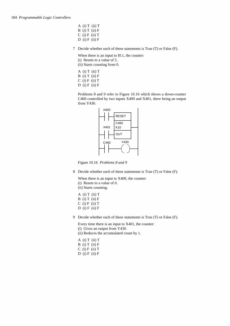
A (i) T (ii) TB (i) T (ii) FC (i) F (ii) TD (i) F (ii) F
7 Decide whether each of these statements is True (T) or False (F).
When there is an input to I0.1, the counter:(i) Resets to a value of 5.(ii) Starts counting from 0.
A (i) T (ii) TB (i) T (ii) FC (i) F (ii) TD (i) F (ii) F
Problems 8 and 9 refer to Figure 10.16 which shows a down-counterC460 controlled by two inputs X400 and X401, there being an outputfrom Y430.
X400
X401
C460
RESET
OUT
C460K10
Y430
Figure 10.16 Problems 8 and 9
8 Decide whether each of these statements is True (T) or False (F).
When there is an input to X400, the counter:(i) Resets to a value of 0.(ii) Starts counting.
A (i) T (ii) TB (i) T (ii) FC (i) F (ii) TD (i) F (ii) F
9 Decide whether each of these statements is True (T) or False (F).
Every time there is an input to X401, the counter:(i) Gives an output from Y430.(ii) Reduces the accumulated count by 1.
A (i) T (ii) TB (i) T (ii) FC (i) F (ii) TD (i) F (ii) F
184 Programmable Logic Controllers

Problems 10 to 12 refer to Figure 10.17 which shows a ladderdiagram involving a counter C460, inputs X400 and X401, internalrelays M100 and M101, and an output Y430.
RESET
C460K10
OUT
X400 M101 M100
X400 M101
C460
X401
M100
Y430 M100
C460
Y430
Figure 10.17 Problems 10 to 12
10 Decide whether each of these statements is True (T) or False (F).
For the output Y430:(i) It switches on the tenth pulse to X400.(ii) It switches off at the start of the eleventh pulse to X400.
A (i) T (ii) TB (i) T (ii) FC (i) F (ii) TD (i) F (ii) F
11 Decide whether each of these statements is True (T) or False (F).
When there is an input to X400:(i) The internal relay M100 is energised.(ii) The internal relay M101 is energised.
A (i) T (ii) TB (i) T (ii) FC (i) F (ii) TD (i) F (ii) F
12 Decide whether each of these statements is True (T) or False (F).
Counters 185
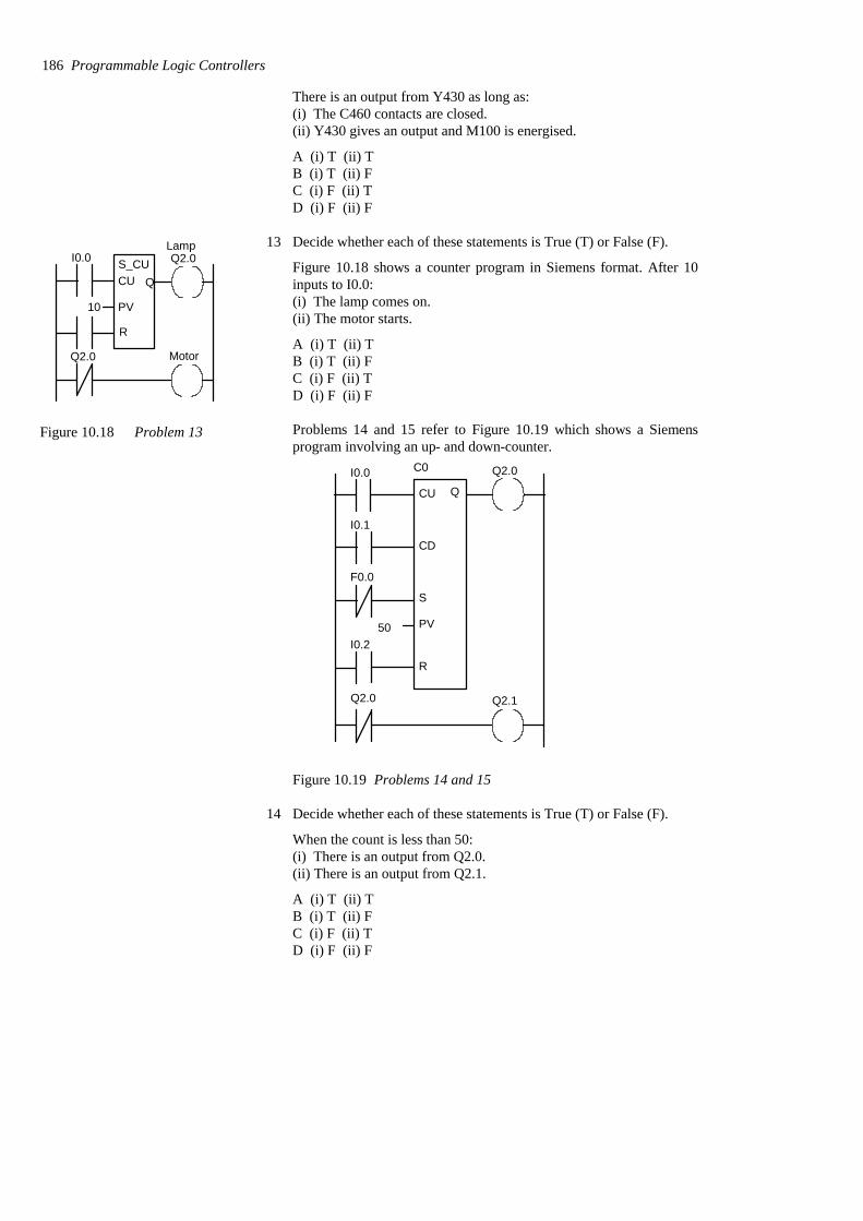
There is an output from Y430 as long as:(i) The C460 contacts are closed.(ii) Y430 gives an output and M100 is energised.
A (i) T (ii) TB (i) T (ii) FC (i) F (ii) TD (i) F (ii) F
13 Decide whether each of these statements is True (T) or False (F).
Figure 10.18 shows a counter program in Siemens format. After 10inputs to I0.0:(i) The lamp comes on.(ii) The motor starts.
A (i) T (ii) TB (i) T (ii) FC (i) F (ii) TD (i) F (ii) F
Problems 14 and 15 refer to Figure 10.19 which shows a Siemensprogram involving an up- and down-counter.
I0.0
I0.1
F0.0
I0.2 50
C0
CU
CD
S
PV
R
Q
Q2.0
Q2.0 Q2.1
Figure 10.19 Problems 14 and 15
14 Decide whether each of these statements is True (T) or False (F).
When the count is less than 50:(i) There is an output from Q2.0.(ii) There is an output from Q2.1.
A (i) T (ii) TB (i) T (ii) FC (i) F (ii) TD (i) F (ii) F
186 Programmable Logic Controllers
I0.0
CU
PV10
Q2.0Lamp
Q2.0 Motor
R
Q
Figure 10.18 Problem 13
S_CU

15 Decide whether each of these statements is True (T) or False (F).
When the count reaches 50:(i) There is an output from Q2.0.(ii) There is an output from Q2.1.
A (i) T (ii) TB (i) T (ii) FC (i) F (ii) TD (i) F (ii) F
Problems 16 and 17 refer to Figure 10.20 which shows a Allen-Bradley program involving an count-up counter.
CTUC5:0Preset 5
I:012/01
CU
DN
C5:0 DN O:013/01
I:012/02 C5:0
RES
Figure 10.20 Problems 16 and 17
16 For the program shown in Figure 10.20, the counter is reset when:
A The count reaches 5.B The count passes 5.C There is an input to I:012/01.D There is an input to I:012/02.
17 Decide whether each of these statements is True (T) or False (F).
For the program shown in Figure 10.20, there is an output atO:013/01 when:(i) There is an input to I:012/01.(ii) There is an output from the count up done bit DN.
A (i) T (ii) TB (i) T (ii) FC (i) F (ii) TD (i) F (ii) F
Problems 18 and 19 refer to Figure 10.21 which shows a Allen-Bradley program involving a count-up counter.
18 Decide whether each of these statements is True (T) or False (F).
When there is a single pulse input to I:012/01:
Counters 187
CTUC5:1Preset 5
I:012/01
CU
DN
C5:1 DN O:013/01
I:012/02 C5:1
RES
Figure 10.21 Problems 18
C5:1 CU O:013/02
and 19
(i) Output O:013/01 is switched on.(ii) Output O:013/02 is switched on.
A (i) T (ii) TB (i) T (ii) FC (i) F (ii) TD (i) F (ii) F
19 Decide whether each of these statements is True (T) or False (F).
When the fifth pulse input occurs to I:012/01:(i) Output O:013/01 is switched on.(ii) Output O:013/02 is switched on.
A (i) T (ii) TB (i) T (ii) FC (i) F (ii) TD (i) F (ii) F
20 Devise ladder programs for systems that will carry out the followingtasks:(a) Give an output after a photocell sensor has given 10 pulse inputsignals as a result of detecting 10 objects passing in front of it.(b) Give an output when the number of people in a store reaches 100,there continually being people entering and leaving the store.
188 Programmable Logic Controllers

11 Shift registers
The term register is used for an electronic device in which data can bestored. An internal relay, see Chapter 7, is such a device. The shiftregister is a number of internal relays grouped together which allowstored bits to be shifted from one relay to another. This chapter is aboutshift registers and how they can be used where a sequence of operations isrequired or to keep track of particular items in a production system.
11.1 Shift registers A register is a number of internal relays grouped together, normally 8, 16or 32. Each internal relay is either effectively open or closed, these statesbeing designated as 0 and 1. The term bit is used for each such binarydigit. Therefore, if we have eight internal relays in the register we canstore eight 0/1 states. Thus we might have:
Internal relays87654321
and each relay might store an on-off signal such that the state of theregister at some instant is:
01001101
i.e. relay 1 is on, relay 2 is off, relay 3 is on, relay 4 is on, relay 5 is off,etc. Such an arrangement is termed an 8-bit register. Registers can be usedfor storing data that originate from input sources other than just simple,single on-off devices such as switches.
With the shift register it is possible to shift stored bits. Shift registersrequire three inputs, one to load data into the first location of the register,one as the command to shift data along by one location and one to reset orclear the register of data. To illustrate this, consider the followingsituation where we start with an 8-bit register in the following state:
01001101
Suppose we now receive the input signal 0. This is an input signal to thefirst internal relay.
Input 001001101→
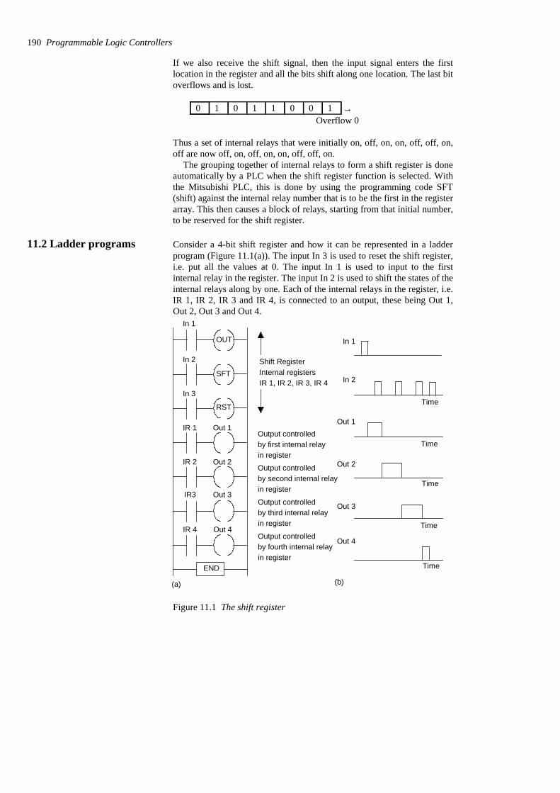
If we also receive the shift signal, then the input signal enters the firstlocation in the register and all the bits shift along one location. The last bitoverflows and is lost.
→10011010 Overflow 0
Thus a set of internal relays that were initially on, off, on, on, off, off, on,off are now off, on, off, on, on, off, off, on.
The grouping together of internal relays to form a shift register is doneautomatically by a PLC when the shift register function is selected. Withthe Mitsubishi PLC, this is done by using the programming code SFT(shift) against the internal relay number that is to be the first in the registerarray. This then causes a block of relays, starting from that initial number,to be reserved for the shift register.
11.2 Ladder programs Consider a 4-bit shift register and how it can be represented in a ladderprogram (Figure 11.1(a)). The input In 3 is used to reset the shift register,i.e. put all the values at 0. The input In 1 is used to input to the firstinternal relay in the register. The input In 2 is used to shift the states of theinternal relays along by one. Each of the internal relays in the register, i.e.IR 1, IR 2, IR 3 and IR 4, is connected to an output, these being Out 1,Out 2, Out 3 and Out 4.
In 1
In 2
In 3
IR 1
IR 2
IR3
Out 1
Out 2
Out 3
IR 4 Out 4
RST
OUT
SFTShift RegisterInternal registersIR 1, IR 2, IR 3, IR 4
Output controlledby first internal relayin register
Output controlledby second internal relayin register
Output controlledby third internal relayin register
Output controlledby fourth internal relayin register
END
In 1
In 2
Out 1
Out 2
Out 3
Out 4
Time
Time
Time
Time
Time
(a) (b)
Figure 11.1 The shift register
190 Programmable Logic Controllers
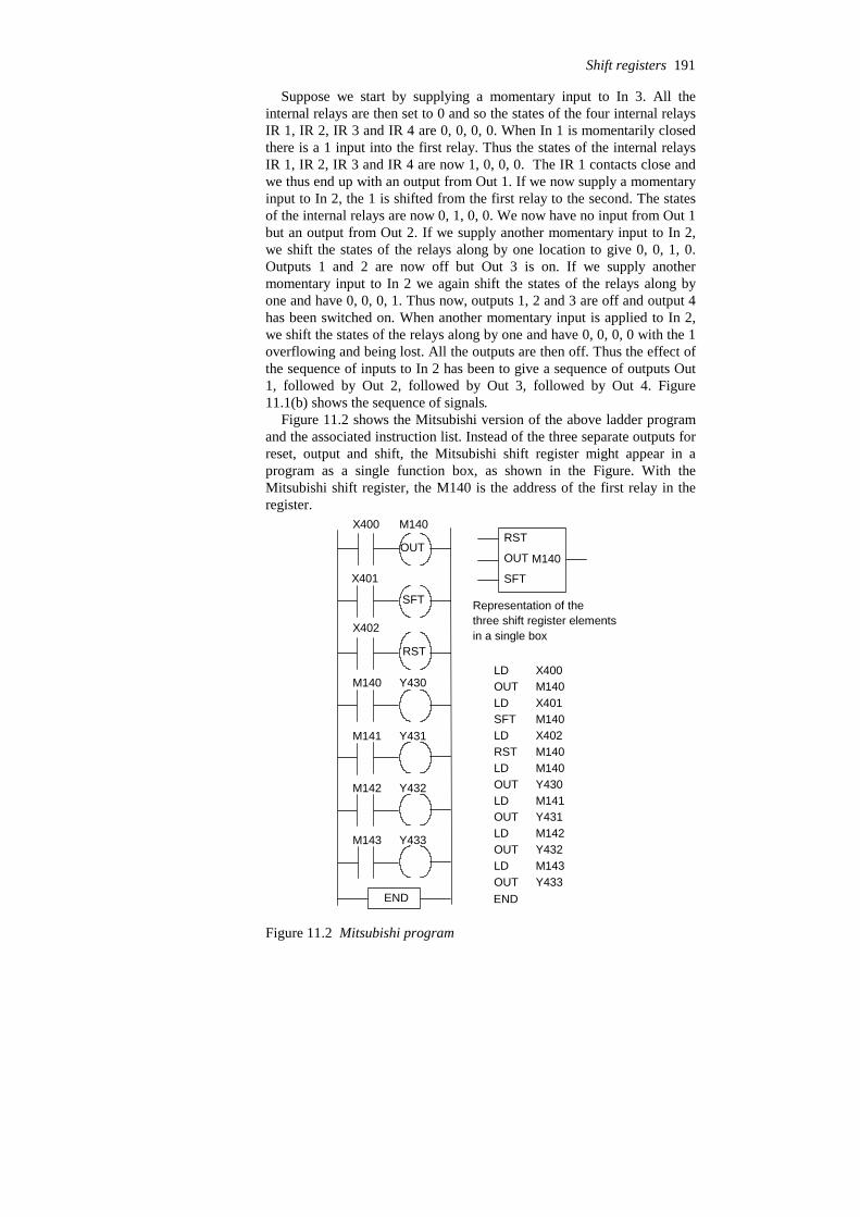
Suppose we start by supplying a momentary input to In 3. All theinternal relays are then set to 0 and so the states of the four internal relaysIR 1, IR 2, IR 3 and IR 4 are 0, 0, 0, 0. When In 1 is momentarily closedthere is a 1 input into the first relay. Thus the states of the internal relaysIR 1, IR 2, IR 3 and IR 4 are now 1, 0, 0, 0. The IR 1 contacts close andwe thus end up with an output from Out 1. If we now supply a momentaryinput to In 2, the 1 is shifted from the first relay to the second. The statesof the internal relays are now 0, 1, 0, 0. We now have no input from Out 1but an output from Out 2. If we supply another momentary input to In 2,we shift the states of the relays along by one location to give 0, 0, 1, 0.Outputs 1 and 2 are now off but Out 3 is on. If we supply anothermomentary input to In 2 we again shift the states of the relays along byone and have 0, 0, 0, 1. Thus now, outputs 1, 2 and 3 are off and output 4has been switched on. When another momentary input is applied to In 2,we shift the states of the relays along by one and have 0, 0, 0, 0 with the 1overflowing and being lost. All the outputs are then off. Thus the effect ofthe sequence of inputs to In 2 has been to give a sequence of outputs Out1, followed by Out 2, followed by Out 3, followed by Out 4. Figure11.1(b) shows the sequence of signals.
Figure 11.2 shows the Mitsubishi version of the above ladder programand the associated instruction list. Instead of the three separate outputs forreset, output and shift, the Mitsubishi shift register might appear in aprogram as a single function box, as shown in the Figure. With theMitsubishi shift register, the M140 is the address of the first relay in theregister.
RST
OUT
SFT
X400 M140
X401
X402
M140 Y430
M141 Y431
M142 Y432
M143 Y433
END
LD
LDSFTLDRSTLDOUTLDOUTLDOUTLDOUT
X400M140X401M140X402M140M140Y430M141Y431M142Y432M143Y433
OUT
END
RST
OUT
SFT
M140
Representation of thethree shift register elementsin a single box
Figure 11.2 Mitsubishi program
Shift registers 191

Figure 11.3 shows a shift register ladder program for a Toshiba PLC.With the Toshiba R016 is the address of the first relay in the register. The(08) indicates that there are eight such relays. D is used for the data input,S for shift input, E for enable or reset input and Q for output.
X007
X000
X001
D
S
E
Q
(08)
R016
R016 Y020
R017 Y021
R018 Y022
R019 Y023
R01A Y024
R01B Y025
R01C Y026
R01D Y027
END
Figure 11.3 Shift register
Figure 11.4 shows the IEC 1131-3 standard symbol for a shift register.The value to be shifted is at input IN and the number of places it is to beshifted is at input N.
Figure 11.5 shows the Siemens symbol for a shift register. If the enableinput EN 1 the shift function is executed and ENO is then 1. If EN is 0 theshift function is not executed and ENO is 0. The shift function SHL_Wshifts the contents of the word variable at input IN bit by bit to the left thenumber of positions specified by the input at N. The shifted word outputis at OUT.
192 Programmable Logic Controllers
IN
N
ANYSHL
BIT
INT
Shift to left
IN
N
ANYSHR
BIT
INT
Shift to right
Figure 11.4 IEC 1131-3 shiftregister symbols
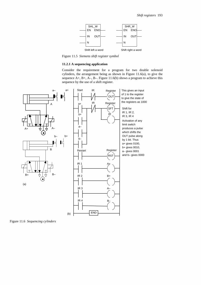
EN
IN
N
ENO
OUT
SHL_W
Shift left a word
EN
IN
N
ENO
OUT
SHR_W
Shift right a word
Figure 11.5 Siemens shift register symbol
11.2.1 A sequencing application
Consider the requirement for a program for two double solenoidcylinders, the arrangement being as shown in Figure 11.6(a), to give thesequence A+, B+, A–, B–. Figure 11.6(b) shows a program to achieve thissequence by the use of a shift register.
Start
Restart
IR 1
IR 2
IR 3
A+
B+
A–
IR 4 B–
RST
OUT
SFT
IR
IR
a+ IR
b+
a–
b–
END
Shift forIR 1, IR 2,IR 3, IR 4
Activation of anylimit switchproduces a pulse
This gives an inputof 1 to the register
which shifts theOUT pulse alongby 1 bit. Thus
Register
Register
Register
to give the state ofthe registers as 1000
a+ gives 0100,b+ gives 0010,a– gives 0001and b– gives 0000
B
b– b+
B+ B–
A
a– a+
A+ A–
(a)
(b)
Figure 11.6 Sequencing cylinders
Shift registers 193

11.2.2 Keeping track of items
The above indicates how a shift register can be used for sequencing.Another application is to keep track of items. For example, a sensor mightbe used to detect faulty items moving along a conveyor and keep track ofit so that when it reaches the appropriate point a reject mechanism isactivated to remove it from the conveyor. Figure 11.7 illustrates thisarrangement and the type of ladder program that might be used.
OUT
SFT
RST
X400 M140
M140
M140
M140
X401
X402
M144X403
M100
M144 M100 Y430 Output to
rejection
Resetting after
M100
(b)END
Items forpackaging
Faulty itemsdeflected fromconveyor
Faulty itemsdetected
(a)
rejection
mechanism
activate
Figure 11.7 Keeping track of faulty items
Each time a faulty item is detected, a pulse signal occurs at input X400.This enters a 1 into the shift register at internal relay M140. When itemsmove, whether faulty or not, there is a pulse input at X401. This shifts the1 along the register. When the 1 reaches internal relay M144, it activatesthe output Y430 and the rejection mechanism removes the faulty itemfrom the conveyor. When an item is removed it is sensed and an input toX403 occurs. This is used to reset the mechanism so that no further itemsare rejected until the rejection signal reaches M144. It does this by givingan output to internal relay M100 which latches the X403 input andswitches the rejection output Y430 off. This represents just the basicelements of a system. A practical system would include further internalrelays in order to make certain that the rejection mechanism is off whengood items move along the conveyor belt and also to disable the inputfrom X400 when the shifting is occurring.
Problems Questions 1 to 9 have four answer options: A, B, C or D. Choose thecorrect answer from the answer options.
194 Programmable Logic Controllers
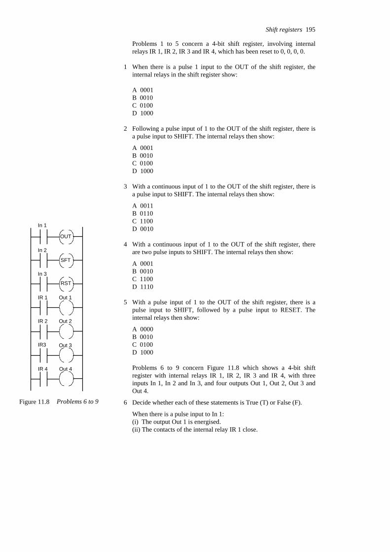
Problems 1 to 5 concern a 4-bit shift register, involving internalrelays IR 1, IR 2, IR 3 and IR 4, which has been reset to 0, 0, 0, 0.
1 When there is a pulse 1 input to the OUT of the shift register, theinternal relays in the shift register show:
A 0001B 0010C 0100D 1000
2 Following a pulse input of 1 to the OUT of the shift register, there isa pulse input to SHIFT. The internal relays then show:
A 0001B 0010C 0100D 1000
3 With a continuous input of 1 to the OUT of the shift register, there isa pulse input to SHIFT. The internal relays then show:
A 0011B 0110C 1100D 0010
4 With a continuous input of 1 to the OUT of the shift register, thereare two pulse inputs to SHIFT. The internal relays then show:
A 0001B 0010C 1100D 1110
5 With a pulse input of 1 to the OUT of the shift register, there is apulse input to SHIFT, followed by a pulse input to RESET. Theinternal relays then show:
A 0000B 0010C 0100D 1000
Problems 6 to 9 concern Figure 11.8 which shows a 4-bit shiftregister with internal relays IR 1, IR 2, IR 3 and IR 4, with threeinputs In 1, In 2 and In 3, and four outputs Out 1, Out 2, Out 3 andOut 4.
6 Decide whether each of these statements is True (T) or False (F).
When there is a pulse input to In 1:(i) The output Out 1 is energised.(ii) The contacts of the internal relay IR 1 close.
Shift registers 195
In 1
In 2
In 3
IR 1
IR 2
IR3
Out 1
Out 2
Out 3
IR 4 Out 4
RST
OUT
SFT
Figure 11.8 Problems 6 to 9

A (i) T (ii) TB (i) T (ii) FC (i) F (ii) TD (i) F (ii) F
7 Decide whether each of these statements is True (T) or False (F).
When there is a pulse input to In 1 followed by a pulse input to SFT:(i) The output Out 1 is energised.(ii) The output Out 2 is energised.
A (i) T (ii) TB (i) T (ii) FC (i) F (ii) TD (i) F (ii) F
8 Decide whether each of these statements is True (T) or False (F).
To obtain the outputs Out 1, Out 2, Out 3 and Out 4 switching on insequence and remaining on, we can have for inputs:(i) A pulse input to In 1 followed by three pulse inputs to SFT.(ii) A continuous input to In 1 followed by three pulse inputs to SFT.
A (i) T (ii) TB (i) T (ii) FC (i) F (ii) TD (i) F (ii) F
9 Initially: Out 1 off, Out 2 off, Out 3 off, Out 4 offNext: Out 1 on, Out 2 off, Out 3 off, Out 4 offNext: Out 1 off, Out 2 on, Out 3 off, Out 4 offNext: Out 1 on, Out 2 off, Out 3 on, Out 4 off
The inputs required to obtain the above sequence are:
A Pulse input to In 1 followed by pulse input to In 2.B Pulse input to In 1 followed by two pulses to In 2.C Pulse input to In 1 followed by pulse input to In 2, followed by
pulse input to In 1.D Pulse input to In 1 followed by pulse input to In 2, followed by
pulse inputs to In 1 and In 2.
10 Devise ladder programs for systems to carry out the following tasks:(a) A sequence of four outputs such that output 1 is switched on whenthe first event is detected and remains on, output 2 is switched onwhen the second event is detected and remains on, output 3 isswitched on when the third event is detected and remains on, output 4is switched on when the fourth event is detected and remains on, andall outputs are switched off when one particular input signal occurs.(b) Control of a paint sprayer in a booth through which items pass onan overhead conveyor so that the paint is switched on when a part isin front of the paint gun and off when there is no part. The items aresuspended from the overhead conveyor by hooks, not every hookhaving an item suspended from it.
196 Programmable Logic Controllers
12 Data handling
Timers, counters and individual internal relays are all concerned with thehandling of individual bits, i.e. single on-off signals. Shift registersinvolve a number of bits with a group of internal relays being linked (seeChapter 11). The block of data in the register is manipulated. This chapteris about PLC operations involving blocks of data representing a value,such blocks being termed words. A block of data is needed if we are torepresent numbers rather than just a single on-off input. Data handlingconsists of operations involving moving or transferring numericinformation stored in one memory word location to another word in adifferent location, comparing data values and carrying out simplearithmetic operations. For example, there might be the need to compare anumeric value with a set value and initiate action if the actual value is lessthan the set value. This chapter is an introductory discussion of suchoperations.
12.1 Registers and bits A register is where data can be stored (see Section 8.1 for an initialdiscussion of registers). In a PLC there are a number of such registers.Each data register can store a binary word of usually 8 or 16 bits. Thenumber of bits determines the size of the number that can be stored. Thebinary system uses only two symbols, 0 and 1 (see Chapter 3). Thus wemight have the 4-bit number 1111. This is the denary number, i.e. thefamiliar number system based on 10s, of 20 + 21 + 22 + 23 = 1 + 2 + 4 + 8= 15. Thus a 4-bit register can store a positive number between 0 and 20 +21 + 22 + 23 or 24 − 1 = 15. An 8-bit register can store a positive numberbetween 0 and 20 + 21 + 22 + 23 + 24 + 25 + 26 + 27 or 28 − 1, i.e. 255. A16-bit register can store a positive number between 0 and 216 − 1, i.e.65 535.
Thus a 16-bit word can be used for positive numbers in the range 0 to+65 535. If negative numbers are required, the most significant bit is usedto represent the sign, a 1 representing a negative number and a 0 apositive number and the format used for the negative numbers is two’scomplement. Two’s complement is a way of writing negative numbers sothat when we add, say, the signed equivalent of +5 and –5 we obtain 0.Thus in this format, 1011 represents the negative number −5 and 0101 thepositive number +5; 1011 + 0101 = (1)0000 with the (1) for the 4-bitnumber being lost. See Chapter 3 for further discussion.
The binary coded decimal (BCD) format is often used with PLCs whenthey are connected to devices such as digital displays. With the naturalbinary number there is no simple link between the separate symbols of adenary number and the equivalent binary number. You have to work outthe arithmetic to establish one number from the other. With the binary
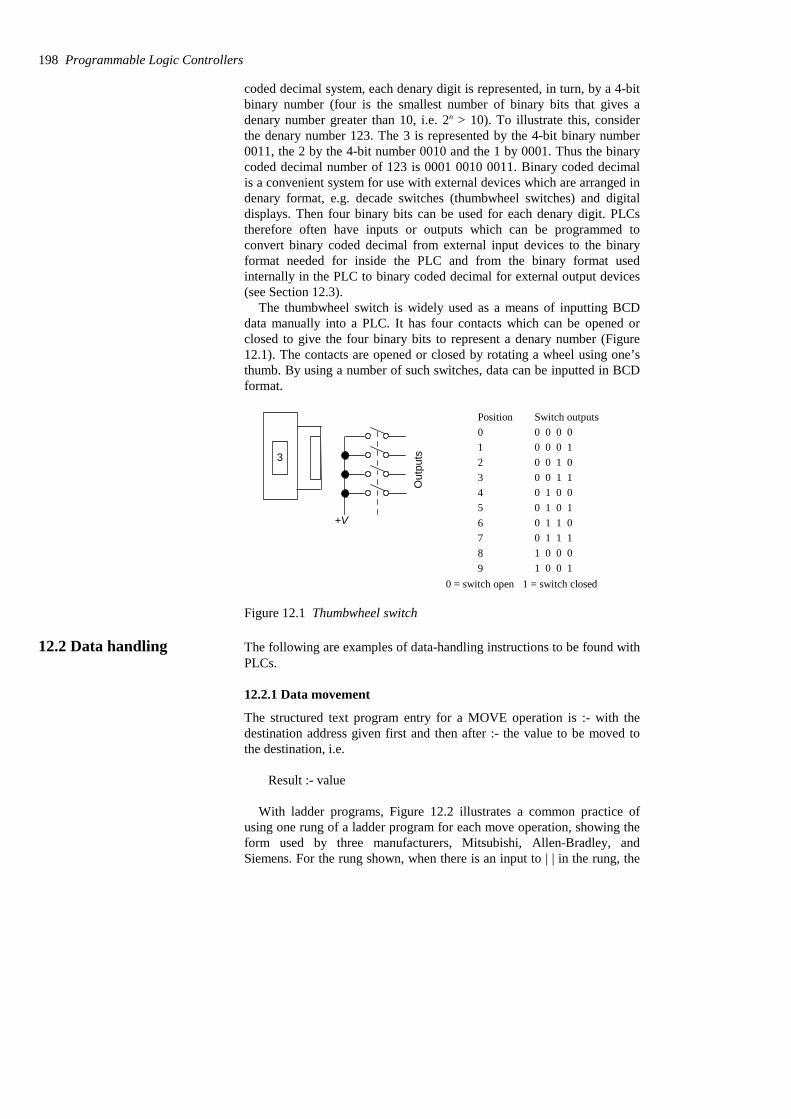
coded decimal system, each denary digit is represented, in turn, by a 4-bitbinary number (four is the smallest number of binary bits that gives adenary number greater than 10, i.e. 2n > 10). To illustrate this, considerthe denary number 123. The 3 is represented by the 4-bit binary number0011, the 2 by the 4-bit number 0010 and the 1 by 0001. Thus the binarycoded decimal number of 123 is 0001 0010 0011. Binary coded decimalis a convenient system for use with external devices which are arranged indenary format, e.g. decade switches (thumbwheel switches) and digitaldisplays. Then four binary bits can be used for each denary digit. PLCstherefore often have inputs or outputs which can be programmed toconvert binary coded decimal from external input devices to the binaryformat needed for inside the PLC and from the binary format usedinternally in the PLC to binary coded decimal for external output devices(see Section 12.3).
The thumbwheel switch is widely used as a means of inputting BCDdata manually into a PLC. It has four contacts which can be opened orclosed to give the four binary bits to represent a denary number (Figure12.1). The contacts are opened or closed by rotating a wheel using one’sthumb. By using a number of such switches, data can be inputted in BCDformat.
3
+V
Out
puts
Switch outputsPosition0123456789
0 0 0 00 0 0 10 0 1 00 0 1 10 1 0 00 1 0 10 1 1 00 1 1 11 0 0 01 0 0 1
0 = switch open 1 = switch closed
Figure 12.1 Thumbwheel switch
12.2 Data handling The following are examples of data-handling instructions to be found withPLCs.
12.2.1 Data movement
The structured text program entry for a MOVE operation is :- with thedestination address given first and then after :- the value to be moved tothe destination, i.e.
Result :- value
With ladder programs, Figure 12.2 illustrates a common practice ofusing one rung of a ladder program for each move operation, showing theform used by three manufacturers, Mitsubishi, Allen-Bradley, andSiemens. For the rung shown, when there is an input to | | in the rung, the
198 Programmable Logic Controllers

move occurs from the designated source address to the designateddestination address. For data handling with these PLCs, the typical ladderprogram data-handling instruction contains the data-handling instruction,the source (S) address from where the data is to be obtained and thedestination (D) address to where it is to be moved. The approach that isused by some manufacturers, e.g. Siemens, is to regard data movement astwo separate instructions, loading data from the source into anaccumulator and then transferring the data from the accumulator to thedestination. Figure 12.2(c) shows the Siemens symbol for the MOVEfunction. The data is moved from the IN input to the OUT output whenEN is enabled.
MOV S D
D1 D2
Source addressDestination address(a)
MOVN7:0N7:2
Source
Destination(b)
MOVE
EN ENO
IN OUT
(c)
Figure 12.2 Data movement: (a) Mitsubishi, (b) Allen-Bradley, (c)Siemens
Data transfers might be to move a preset value to a timer or counter, ora time or counter value to some register for storage, or data from an inputto a register or a register to output. Figure 12.3 shows the rung, in theAllen-Bradley format, that might be used to transfer a number held ataddress N7:0 to the preset of timer T4:6 when the input conditions for thatrung are met. A data transfer from the accumulated value in a counter to aregister would have a source address of the form C5:18.ACC and adestination address of the form N7:0. A data transfer from an input to aregister might have a source address of the form I:012 and a destinationaddress of the form N7:0. A data transfer from a register to an outputmight have a source address of the form N7:0 and a destination address ofthe form O:030.
MOVN7:0
Source
Destination
T4:6.PRE
Figure 12.3 Moving number to timer preset
Data handling 199
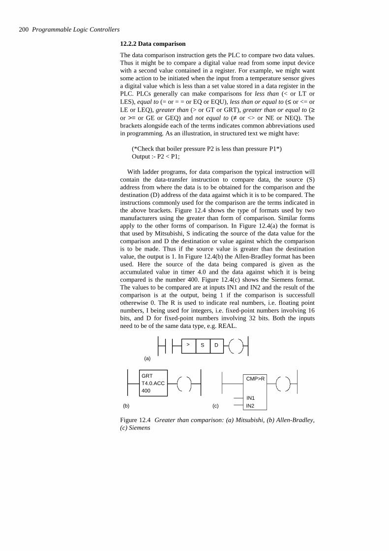
12.2.2 Data comparison
The data comparison instruction gets the PLC to compare two data values.Thus it might be to compare a digital value read from some input devicewith a second value contained in a register. For example, we might wantsome action to be initiated when the input from a temperature sensor givesa digital value which is less than a set value stored in a data register in thePLC. PLCs generally can make comparisons for less than (< or LT orLES), equal to (= or = = or EQ or EQU), less than or equal to (≤ or <= orLE or LEQ), greater than (> or GT or GRT), greater than or equal to (≥or >= or GE or GEQ) and not equal to (≠ or <> or NE or NEQ). Thebrackets alongside each of the terms indicates common abbreviations usedin programming. As an illustration, in structured text we might have:
(*Check that boiler pressure P2 is less than pressure P1*)Output :- P2 < P1;
With ladder programs, for data comparison the typical instruction willcontain the data-transfer instruction to compare data, the source (S)address from where the data is to be obtained for the comparison and thedestination (D) address of the data against which it is to be compared. Theinstructions commonly used for the comparison are the terms indicated inthe above brackets. Figure 12.4 shows the type of formats used by twomanufacturers using the greater than form of comparison. Similar formsapply to the other forms of comparison. In Figure 12.4(a) the format isthat used by Mitsubishi, S indicating the source of the data value for thecomparison and D the destination or value against which the comparisonis to be made. Thus if the source value is greater than the destinationvalue, the output is 1. In Figure 12.4(b) the Allen-Bradley format has beenused. Here the source of the data being compared is given as theaccumulated value in timer 4.0 and the data against which it is beingcompared is the number 400. Figure 12.4(c) shows the Siemens format.The values to be compared are at inputs IN1 and IN2 and the result of thecomparison is at the output, being 1 if the comparison is successfullotherewise 0. The R is used to indicate real numbers, i.e. floating pointnumbers, I being used for integers, i.e. fixed-point numbers involving 16bits, and D for fixed-point numbers involving 32 bits. Both the inputsneed to be of the same data type, e.g. REAL.
>
(a)
GRTT4.0.ACC400
(b)
S D
CMP>R
IN1IN2(c)
Figure 12.4 Greater than comparison: (a) Mitsubishi, (b) Allen-Bradley,(c) Siemens
200 Programmable Logic Controllers
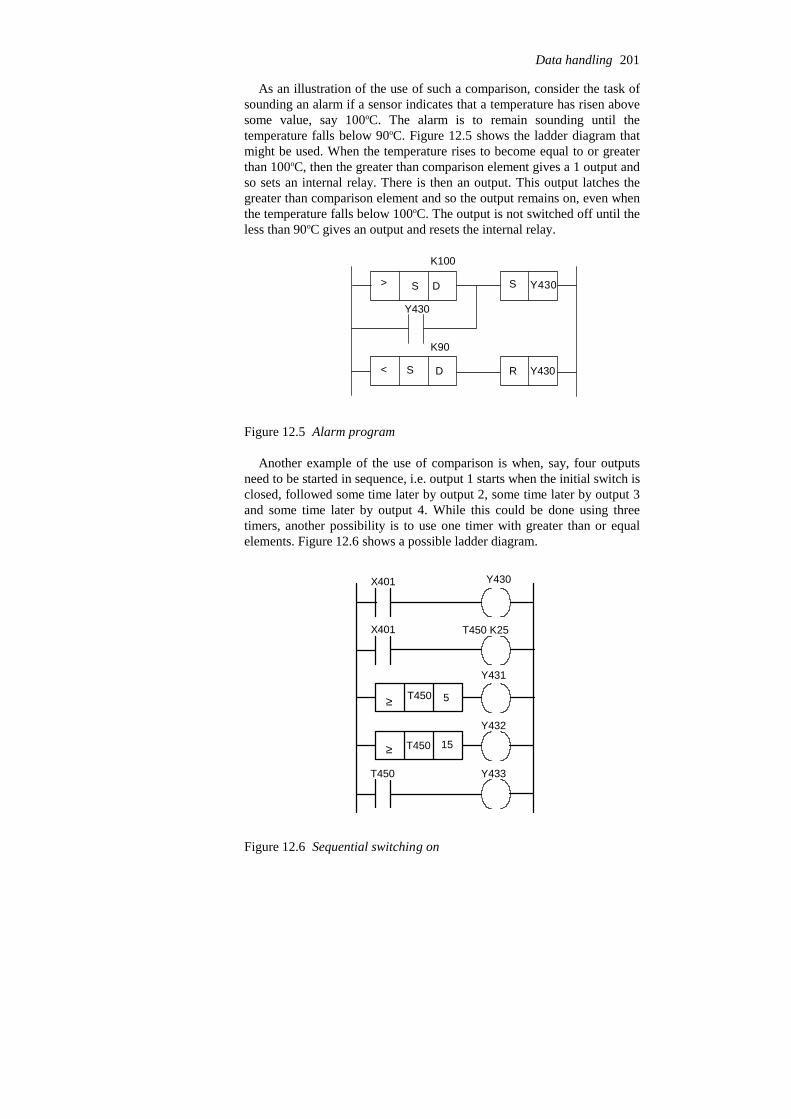
As an illustration of the use of such a comparison, consider the task ofsounding an alarm if a sensor indicates that a temperature has risen abovesome value, say 100oC. The alarm is to remain sounding until thetemperature falls below 90oC. Figure 12.5 shows the ladder diagram thatmight be used. When the temperature rises to become equal to or greaterthan 100oC, then the greater than comparison element gives a 1 output andso sets an internal relay. There is then an output. This output latches thegreater than comparison element and so the output remains on, even whenthe temperature falls below 100oC. The output is not switched off until theless than 90oC gives an output and resets the internal relay.
>
<
S
R
Y430
Y430
Y430
D
DS
S
K100
K90
Figure 12.5 Alarm program
Another example of the use of comparison is when, say, four outputsneed to be started in sequence, i.e. output 1 starts when the initial switch isclosed, followed some time later by output 2, some time later by output 3and some time later by output 4. While this could be done using threetimers, another possibility is to use one timer with greater than or equalelements. Figure 12.6 shows a possible ladder diagram.
Y430X401
X401 T450 K25
≥
≥
T450 5
T450 15
Y431
Y432
Y433T450
Figure 12.6 Sequential switching on
Data handling 201

When the X401 contacts close the output Y430 starts. Also the timer isstarted. When the timer accumulated value reaches 5 s then the greaterthan or equal to element switches on Y431. When the timer accumulatedvalue reaches 15 s then the greater than or equal to element switches onY432. When the timer reaches 25 s then its contacts switch on Y433.
12.3 Arithmetic functions Most PLCs provide BCD-to-binary and binary-to-BCD conversions foruse when the input might be for a thumbwheel switch or the output to adecimal display. Figure 12.7(a) shows the typical form of instructions foruse in such situations and Figure 12.7(b) the form used by Siemens.
BIN S D
(a)
Source
Destination
BCD S D
Source
Destination
EN
IN
OUT
ENO
BCD_I
EN
IN
OUT
ENO
I_BCD
(b)
Figure 12.7 Conversion: (a) BCD-to-binary and binary-to-BCD, (b)BCD-to-integer and integer-to-BCD
12.3.1 Arithmetic operations
Some PLCs are equipped to carry out just the arithmetic operations ofaddition and subtraction, others the four basic arithmetic operations ofaddition, subtraction, multiplication and division, while others can carryout these and various other functions such as the exponential. Additionand subtraction operations are used to alter the value of data held in dataregisters. For example, this might be to adjust a sensor input reading orperhaps obtain a value by subtracting two sensor values or alter the presetvalues used by timers and counters. Multiplication might be used tomultiply some input before perhaps adding to or subtracting it fromanother.
The way in which PLCs have to be programmed to carry out suchoperations varies. Allen-Bradley in some of their PLCs use a compute(CPT) instruction. This is an output instruction that performs theoperations defined and then writes the results to a specified destinationaddress. Figure 12.8 shows the instruction format. When the computeinstruction is on the programming screen, the destination has to be firstentered, then the expression. Thus we might have a destination ofT4:1.ACC and an expression (N7:1 + N10:1)*3.5. Note that the symbol *is used for multiplication. The expression states that the value in N7:1 isto be added to the value in N10:1. This sum is then to be multiplied by3.5. The result is then to be sent to the destination which is theaccumulated value in timer 4.1.
202 Programmable Logic Controllers
COMPUTEDestinationExpression
CPT
Figure 12.8 Allen-Bradleyformat
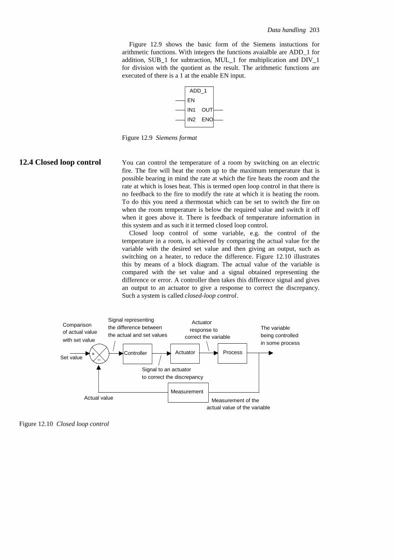
Figure 12.9 shows the basic form of the Siemens instuctions forarithmetic functions. With integers the functions avaialble are ADD_1 foraddition, SUB_1 for subtraction, MUL_1 for multiplication and DIV_1for division with the quotient as the result. The arithmetic functions areexecuted of there is a 1 at the enable EN input.
ADD_1
EN
IN1
IN2
OUT
ENO
Figure 12.9 Siemens format
12.4 Closed loop control You can control the temperature of a room by switching on an electricfire. The fire will heat the room up to the maximum temperature that ispossible bearing in mind the rate at which the fire heats the room and therate at which is loses heat. This is termed open loop control in that there isno feedback to the fire to modify the rate at which it is heating the room.To do this you need a thermostat which can be set to switch the fire onwhen the room temperature is below the required value and switch it offwhen it goes above it. There is feedback of temperature information inthis system and as such it it termed closed loop control.
Closed loop control of some variable, e.g. the control of thetemperature in a room, is achieved by comparing the actual value for thevariable with the desired set value and then giving an output, such asswitching on a heater, to reduce the difference. Figure 12.10 illustratesthis by means of a block diagram. The actual value of the variable iscompared with the set value and a signal obtained representing thedifference or error. A controller then takes this difference signal and givesan output to an actuator to give a response to correct the discrepancy.Such a system is called closed-loop control.
The variablebeing controlled
Measurement
Comparisonof actual valuewith set value
+–
Signal representingthe difference betweenthe actual and set values
ControllerSet value
Actual value Measurement of theactual value of the variable
Actuator Process
in some process
Signal to an actuatorto correct the discrepancy
Actuatorresponse to
correct the variable
Figure 12.10 Closed loop control
Data handling 203

Figure 12.11 shows the arrangement that might be used with a PLCused to exercise the closed-loop control. It has been assumed that theactuator and the measured values are analogue and thus requireconversion to digital; analogue-to-digital and digital-to-analogue unitshave thus been shown.
The variablebeing controlled
MeasurementActual value
Actuator Processin some process
PLC
Set value
ADC DAC
Figure 12.11 PLC for closed-loop control
12.4.1 Modes of control
With proportional control the controller gives an output to the actuatorwhich is proportional to the difference between the actual value and theset value of the variable, i.e. the error (Figure 12.12(a)). Such a form ofcontrol can be given by a PLC with basic arithmetic facilities. The setvalue and the actual values are likely to be analogue and so are convertedto digital and then the actual value is subtracted from the set value and thedifference multiplied by some constant, the proportional constant KP, togive the output, which after conversion to analogue is the correction signalapplied to the actuator:
controller output = KP % error
Con
trolle
r out
put
0 Error(a)
Erro
rC
ontro
ller o
utpu
t
Time
Time
0
0(b)
Erro
r
0 Time
0 Time
Con
trolle
rou
tput
(c)
Figure 12.12 Control: (a) proportional, (b) integral, (c) derivative
204 Programmable Logic Controllers
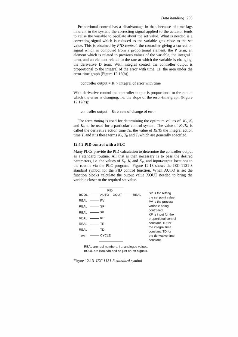
Proportional control has a disadvantage in that, because of time lagsinherent in the system, the correcting signal applied to the actuator tendsto cause the variable to oscillate about the set value. What is needed is acorrecting signal which is reduced as the variable gets close to the setvalue. This is obtained by PID control, the controller giving a correctionsignal which is computed from a proportional element, the P term, anelement which is related to previous values of the variable, the integral Iterm, and an element related to the rate at which the variable is changing,the derivative D term. With integral control the controller output isproportional to the integral of the error with time, i.e. the area under theerror-time graph (Figure 12.12(b)).
controller output = KI % integral of error with time
With derivative control the controller output is proportional to the rate atwhich the error is changing, i.e. the slope of the error-time graph (Figure12.12(c)):
controller output = KD % rate of change of error
The term tuning is used for determining the optimum values of KP, KI
and KD to be used for a particular control system. The value of KD/KP iscalled the derivative action time TD, the value of KP/KI the integral actiontime TI and it is these terms KP, TD and TI which are generally specified.
12.4.2 PID control with a PLC
Many PLCs provide the PID calculation to determine the controller outputas a standard routine. All that is then necessary is to pass the desiredparameters, i.e. the values of KP, KI and KD, and input/output locations tothe routine via the PLC program. Figure 12.13 shows the IEC 1131-3standard symbol for the PID control function. When AUTO is set thefunction blocks calculate the output value XOUT needed to bring thevariable closer to the required set value.
PIDAUTO
PV
SP
X0
KP
TR
TD
CYCLE
XOUT REALBOOL
REAL
REAL
REAL
REAL
REAL
REAL
TIME
SP is for settingthe set point value.PV is the processvariable beingcontrolled.KP is input for the proportional controlconstant, TR forthe integral timeconstant, TD forthe derivative time constant.
REAL are real numbers, i.e. analogue values.BOOL are Boolean and so just on-off signals.
Figure 12.13 IEC 1131-3 standard symbol
Data handling 205
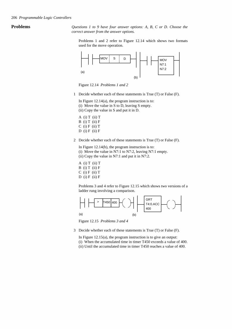
Problems Questions 1 to 9 have four answer options: A, B, C or D. Choose thecorrect answer from the answer options.
Problems 1 and 2 refer to Figure 12.14 which shows two formatsused for the move operation.
MOV S D MOVN7:1N7:2
(a)
(b)
Figure 12.14 Problems 1 and 2
1 Decide whether each of these statements is True (T) or False (F).
In Figure 12.14(a), the program instruction is to:(i) Move the value in S to D, leaving S empty.(ii) Copy the value in S and put it in D.
A (i) T (ii) TB (i) T (ii) FC (i) F (ii) TD (i) F (ii) F
2 Decide whether each of these statements is True (T) or False (F).
In Figure 12.14(b), the program instruction is to:(i) Move the value in N7:1 to N7:2, leaving N7:1 empty.(ii) Copy the value in N7:1 and put it in N7:2.
A (i) T (ii) TB (i) T (ii) FC (i) F (ii) TD (i) F (ii) F
Problems 3 and 4 refer to Figure 12.15 which shows two versions of aladder rung involving a comparison.
>
(a)
GRTT4:0.ACC400
(b)
T450 400
Figure 12.15 Problems 3 and 4
3 Decide whether each of these statements is True (T) or False (F).
In Figure 12.15(a), the program instruction is to give an output:(i) When the accumulated time in timer T450 exceeds a value of 400.(ii) Until the accumulated time in timer T450 reaches a value of 400.
206 Programmable Logic Controllers
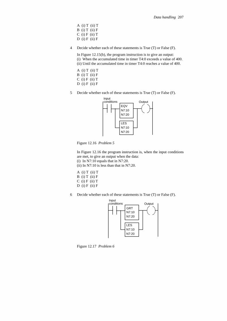
A (i) T (ii) TB (i) T (ii) FC (i) F (ii) TD (i) F (ii) F
4 Decide whether each of these statements is True (T) or False (F).
In Figure 12.15(b), the program instruction is to give an output:(i) When the accumulated time in timer T4:0 exceeds a value of 400.(ii) Until the accumulated time in timer T4:0 reaches a value of 400.
A (i) T (ii) TB (i) T (ii) FC (i) F (ii) TD (i) F (ii) F
5 Decide whether each of these statements is True (T) or False (F).
EQVN7:10N7:20
LESN7:10N7:20
Inputconditions Output
Figure 12.16 Problem 5
In Figure 12.16 the program instruction is, when the input conditionsare met, to give an output when the data:(i) In N7:10 equals that in N7:20.(ii) In N7:10 is less than that in N7:20.
A (i) T (ii) TB (i) T (ii) FC (i) F (ii) TD (i) F (ii) F
6 Decide whether each of these statements is True (T) or False (F).
N7:10N7:20
LESN7:10N7:20
Inputconditions Output
GRT
Figure 12.17 Problem 6
Data handling 207

In Figure 12.17, the program instruction is to give, when the inputconditions are met, an output when:(i) The data in N7:10 is not equal to that in N7:20.(ii) The data in N7:10 is greater or less than that in N7:20.
A (i) T (ii) TB (i) T (ii) FC (i) F (ii) TD (i) F (ii) F
7 In Figure 12.18, when the input conditions are met, the programinstruction is to give in N7:20:
CPTN7:20N7:11*N7:12
Figure 12.18 Problem 7
A The sum of the data in N7:11 and N7:12.B The product of the data in N7:11 and N7:12.C The difference between the data in N7:11 and N7:12.D The value given by dividing the data in N7:11 by that in N7:12.
8 Decide whether each of these statements is True (T) or False (F).
CMP > = R
IN1
IN2
Output
Figure 12.19 Problem 8
For the Siemens function box shown in Figure 12.19, the output willbe set when:(i) Inputs IN1 and IN2 are both the same REAL number.(ii) Input IN1 is a REAL number greater than input IN2.
A (i) T (ii) TB (i) T (ii) FC (i) F (ii) TD (i) F (ii) F
9 Decide whether each of these statements is True (T) or False (F).
208 Programmable Logic Controllers
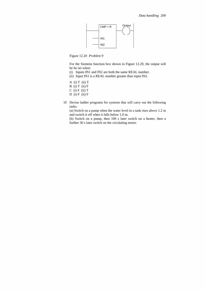
CMP > R
IN1
IN2
Output
Figure 12.20 Problem 9
For the Siemens function box shown in Figure 12.20, the output willbe be set when:(i) Inputs IN1 and IN2 are both the same REAL number.(ii) Input IN1 is a REAL number greater than input IN2.
A (i) T (ii) TB (i) T (ii) FC (i) F (ii) TD (i) F (ii) F
10 Devise ladder programs for systems that will carry out the followingtasks:(a) Switch on a pump when the water level in a tank rises above 1.2 mand switch it off when it falls below 1.0 m.(b) Switch on a pump, then 100 s later switch on a heater, then afurther 30 s later switch on the circulating motor.
Data handling 209
13 Designing systems
This chapter considers how programs are designed and how they and aPLC system can be tested and faults found. This involves consideration ofboth the hardware and the software.
13.1 Program development Whatever the language in which a program is to be written, a systematicapproach to the problem can improve the chance of high quality programsbeing generated in as short a time as possible. A systematic designtechnique is likely to involve the following steps:
1 A definition of what is required with the inputs and outputs specified.2 A definition of the algorithm to be used. An algorithm is a
step-by-step sequence which defines a method of solving theproblem. This can often be shown by a flow chart or written inpseudocode, this involving the use of the words BEGIN, DO, END,IF-THEN-ELSE, WHILE-DO.
3 The algorithm is then translated into instructions that can be inputtedto the PLC. Because programs are often very long and can end updifficult to write as a long single block and even more difficult tolater follow for fault finding and maintenance, it is advisable to breakthe program down into areas which are then further subdivided untilmanageable size blocks of program occur. This is termed top-downdesign.
4 The program is then tested and debugged.5 The program is documented so that any person using or having to
modify the program at a later date understands how the programworks.
13.1.1 Flow charts and pseudocode
Figure 13.1(a) shows the symbols used in flow charts. Each step of analgorithm is represented by one or more of these symbols and linked bylines to represent the program flow, Figure 13.1(b) illustrating this.Pseudocode is a way of describing the steps in an algorithm in an informalway.
Consider how the following program operations can be represented byflow charts and pseudocode and then programmed using ladder andsequential function chart programming:
1 SequentialConsider a sequence when event A has to be followed by event B.Figure 13.2(a) shows how this can be represented by a flow chart.

Start/end Process oraction
Input/output
Decision
Program flowdirection
Connector
or
Subroutine
(a) (b)
START
OperationA
OperationB
OperationC
YES
NO
Isoutputhigh?
Figure 13.1 (a) Flow chart symbols, (b) example of a simple flow chart
A
B
Output A
Output A
Output B
(a)
(b)
STARTSTART
(c)
Start
START
Step A A
Step B B
Output A
Figure 13.2 Sequence
In pseudocode this is written as:
BEGIN ADO A
END ABEGIN B
DO BEND B
A sequence can be translated into a ladder program in the way shownin Figure 13.2(b). When the start input occurs then output A happens.When action A happens it operates output A relay and results inoutput B occurring. Figure 13.2(c) shows the sequential functionchart representation of a sequence.
Designing systems 211

2 ConditionalFigure 13.3(a) shows the flow chart for when A or B is to happen if aparticular condition X being YES or NO occurs. The pseudocode todescribe this involves the words IF-THEN-ELSE-ENDIF.
IF XTHEN
BEGIN ADO AEND A
ELSEBEGIN BDO BEND B
ENDIF X
Such a condition can be represented by the ladder diagram shown inFigure 13.3(b). When the start input occurs, the output will be A ifthere is an input to X, otherwise the output is B. Figure 13.3(c) showsthe sequential function chart for such selective branching.
XYES NO
A B
(a)
START
START
X
X
Output A
Output B
(b)
START
Output A
Output B
Start
Start
X = 1 X = 0
Step A Step BA B
A B
(c)
Start step
Note that twosteps can neverbe directly linked,always having tobe separatedby a transition
Figure 13.3 Conditional
212 Programmable Logic Controllers

3 LoopingA loop is a repetition of some element of a program, the elementbeing repeated as long as some condition prevails. Figure 13.4(a)shows how this can be represented by a flow chart. As long ascondition X is realised then the sequence A followed by B occurs andis repeated. When X is no longer realised then the program continuesand the looping through A and B ceases.
XYES
NO A
B
X Ouput A
Output B
X
X
Rest of program
Input AX
While X yes output A,which when completedgives input A as yes and sooutput B.
Rest of program occurswhile not X
latches the START.
(b)
(a)
START START
START
Output B
Output B
When B happens it
and so the decision Xis faced again.
Start
Output AStep A
X = 1
Output Step C
X = 0
START = 1
And so on
Output BStep B
(c)
Startstep
Figure 13.4 Looping
In pseudocode this can be represented by using the wordsWHILE-DO -ENDWHILE:
WHILE X
Designing systems 213
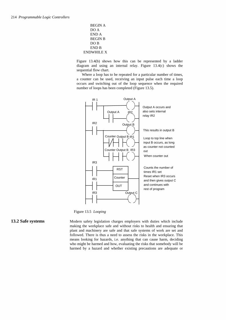
BEGIN ADO AEND ABEGIN BDO BEND B
ENDWHILE X
Figure 13.4(b) shows how this can be represented by a ladderdiagram and using an internal relay. Figure 13.4(c) shows thesequential flow chart.
Where a loop has to be repeated for a particular number of times,a counter can be used, receiving an input pulse each time a loopoccurs and switching out of the loop sequence when the requirednumber of loops has been completed (Figure 13.5).
Output A
Output B
IR 1
Counter
RST
OUT
IR2
IR2Output A
IR3
IR1
IR3 Output C
Counter
Counter
IR1
IR3
Output B
Output B
Loop to top line when
Output A occurs andalso sets internalrelay IR2
This results in output B
input B occurs, as longas counter not countedoutWhen counter out
Counts the number oftimes IR1 setReset when IR3 occursand then gives output Cand continues withrest of program
Figure 13.5 Looping
13.2 Safe systems Modern safety legislation charges employers with duties which includemaking the workplace safe and without risks to health and ensuring thatplant and machinery are safe and that safe systems of work are set andfollowed. There is thus a need to assess the risks in the workplace. Thismeans looking for hazards, i.e. anything that can cause harm, decidingwho might be harmed and how, evaluating the risks that somebody will beharmed by a hazard and whether existing precautions are adequate or
214 Programmable Logic Controllers

whether more needs to be done to reduce the chance of harm occurring,recording the findings and reviewing and revising the assessment ifnecessary.
Thus, for example, issues such as emergency stops and access doors onequipment need to be considered, the risks assessed and safe systems thendesigned. With regard to access doors on equipment, switch contacts canbe used on such doors so that the system is stopped if the doors are notcorrectly guarding equipment.
An important standard is IEC (International ElectrotechnicalCommission) 61508: Functional safety of electrical/electronic/programmable electronic safety-related systems. The standard is in sevenparts, namely Part 1: General requirements; Part 2: Requirements forE/E/PE safety-related systems; Part 3: Software requirements; Part 4:Definitions and abbreviations; Part 5: Examples of methods for thedetermination of safety integrity levels; Part 6: Guidelines on theapplication of IEC 61508-2 and IEC 61508-3; Part 7: Overview oftechniques and measures. In order to provide functional safety of amachine or plant, the safety-related protective or control system mustfunction correctly and when a failure occurs it must operate so that theplant or machine is brought into a safe shut-down state.
13.2.1 PLC systems and safety
Safety must be a priority in the design of a PLC system. Thus, emergencystop buttons and safety guard switches must be hard wired and not dependon the PLC software for implementation so that, in the situation wherethere is a failure of the stop switch or PLC, the system is automaticallysafe. The system must be fail-safe.
With a PLC system, a stop signal can be provided by a switch as shownin Figure 13.6. This arrangement is unsafe as an emergency stop becauseif there is a fault and the switch cannot be operated, then no stop signalcan be provided. Thus to start we momentarily close the press-button startswitch and the motor control internal relay then latches this closure andthe output remains on. To stop we have to momentarily open the stopswitch; this unlatches the start switch. However, if the stop switch cannotbe operated then we cannot stop the system. What we require is a systemthat will still stop if a failure occurs in the stop switch.
StopStartStart
Stop
PLC
Motor control
Motor
Motor control relay
Motor
relay
Figure 13.6 An unsafe stop system
We can achieve this by the arrangement shown in Figure 13.7. Theprogram has the stop switch as open contacts. However, because the
Designing systems 215
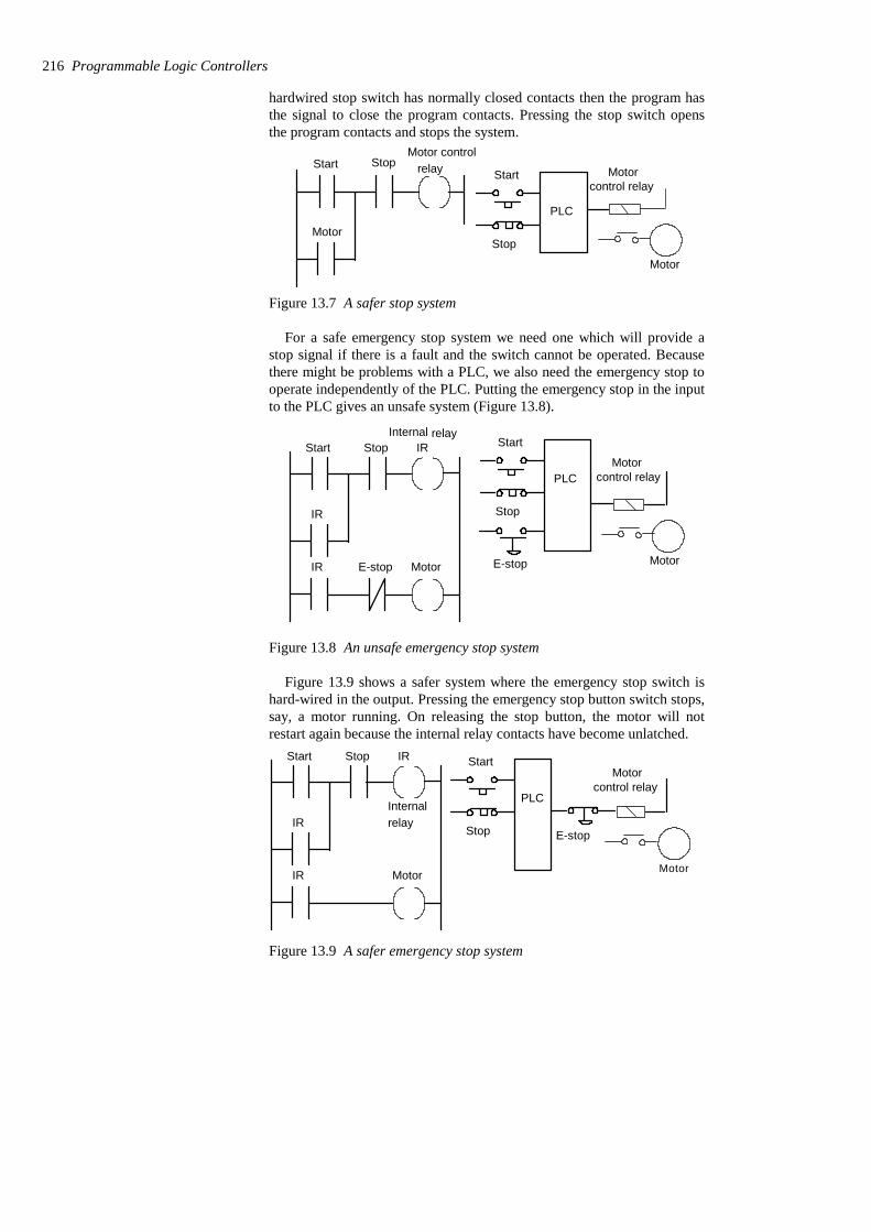
hardwired stop switch has normally closed contacts then the program hasthe signal to close the program contacts. Pressing the stop switch opensthe program contacts and stops the system.
Motor
StopStartStart
Stop
PLC
Motor control
Motorcontrol relay
Motor
relay
Figure 13.7 A safer stop system
For a safe emergency stop system we need one which will provide astop signal if there is a fault and the switch cannot be operated. Becausethere might be problems with a PLC, we also need the emergency stop tooperate independently of the PLC. Putting the emergency stop in the inputto the PLC gives an unsafe system (Figure 13.8).
StopStart Start
Stop
PLC
IRInternal relay
IR E-stop Motor
IR
E-stop
Motorcontrol relay
Motor
Figure 13.8 An unsafe emergency stop system
Figure 13.9 shows a safer system where the emergency stop switch ishard-wired in the output. Pressing the emergency stop button switch stops,say, a motor running. On releasing the stop button, the motor will notrestart again because the internal relay contacts have become unlatched.
StopStart Start
Stop
PLC
IR
Internalrelay
IR Motor
IRE-stop
Motorcontrol relay
Motor
Figure 13.9 A safer emergency stop system
216 Programmable Logic Controllers
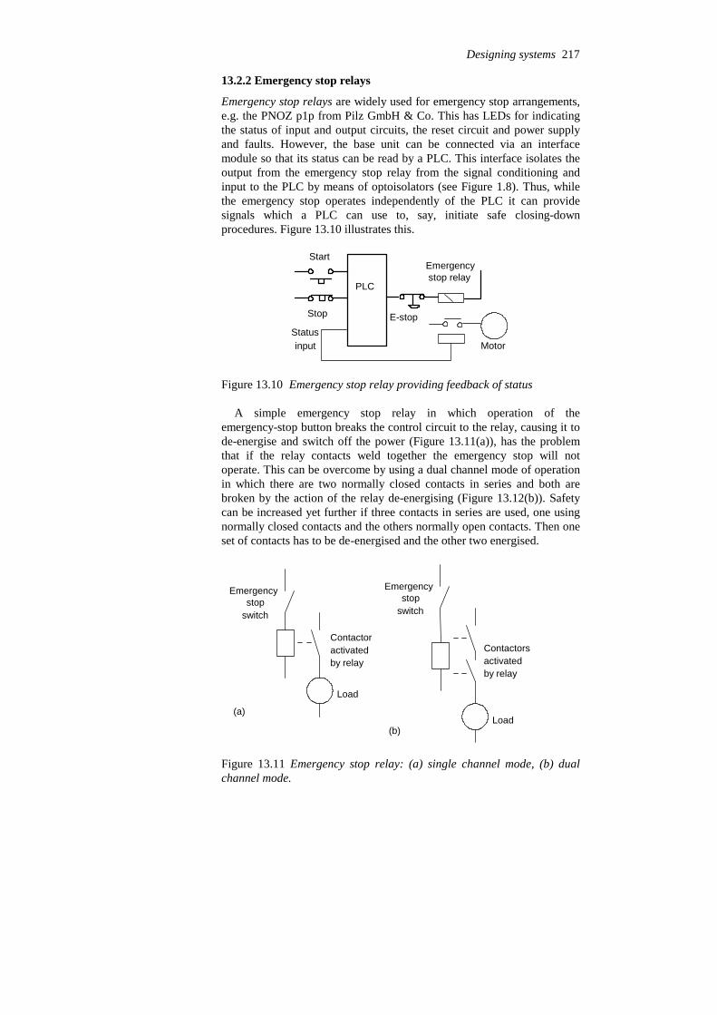
13.2.2 Emergency stop relays
Emergency stop relays are widely used for emergency stop arrangements,e.g. the PNOZ p1p from Pilz GmbH & Co. This has LEDs for indicatingthe status of input and output circuits, the reset circuit and power supplyand faults. However, the base unit can be connected via an interfacemodule so that its status can be read by a PLC. This interface isolates theoutput from the emergency stop relay from the signal conditioning andinput to the PLC by means of optoisolators (see Figure 1.8). Thus, whilethe emergency stop operates independently of the PLC it can providesignals which a PLC can use to, say, initiate safe closing-downprocedures. Figure 13.10 illustrates this.
Start
Stop
PLC
E-stop
Motor
Emergencystop relay
Statusinput
Figure 13.10 Emergency stop relay providing feedback of status
A simple emergency stop relay in which operation of theemergency-stop button breaks the control circuit to the relay, causing it tode-energise and switch off the power (Figure 13.11(a)), has the problemthat if the relay contacts weld together the emergency stop will notoperate. This can be overcome by using a dual channel mode of operationin which there are two normally closed contacts in series and both arebroken by the action of the relay de-energising (Figure 13.12(b)). Safetycan be increased yet further if three contacts in series are used, one usingnormally closed contacts and the others normally open contacts. Then oneset of contacts has to be de-energised and the other two energised.
Emergencystop
switch
Contactoractivated by relay
Load
(a)
Emergencystop
switch
Contactorsactivated by relay
Load(b)
Figure 13.11 Emergency stop relay: (a) single channel mode, (b) dualchannel mode.
Designing systems 217
Such types of stop-relays systems are used with so-called ‘lightcurtains’. A danger zone, such as a packaging machine, is protected frompeople getting too close by infrared beams. If a light beam is broken itimmediately triggers a safe shutdown command. Safety mats are anotherway of detecting when someone is too close to a machine. They are placedround a machine and when someone steps on the mat a contact is closedwhich causes the machine to stop.
Thus a safe-operating system for a work cell might use gated entrysystems, e.g. guards on machines which activate stop relays if they are notin place, light curtains and emergency stop relays.
13.2.3 Safety PLCs
Safety PLCs are specially designed PLCs to enable safety functions to berealised. In a safety PLC there can be two or three microprocessors thatperform exactly the same logic, check against each other and only giveoutputs if there is agreement. An example of such a PLC is the SIMATICS5-95F. This is a two-channel system with two identical sub-systemswhich communicate with each other via a fibre-optic cable link. Theinputs from the sensors are fed simultaneously to both sub-systems.During operation, data is passed via the fibre-optic cable between the twosub-systems. They operate in synchronism with the same program andcompare input and output signals, the results of logic operations, counters,etc. and automatically goes into a safe stop condition if there are differentoutputs or internal faults or failures. For safety-related digital outputs,actuators are switched on or off from both sub-systems. This means thatone sub-system can alone shut down equipment.
13.3 Commissioning Commissioning of a PLC system involves:
1 Checking that all the cable connections between the PLC and theplant being controlled are complete, safe and to the requiredspecification and meeting local standards.
2 Checking that the incoming power supply matches the voltage settingfor which the PLC is set.
3 Checking that all protective devices are set to their appropriate tripsettings.
4 Checking that emergency stop buttons work.5 Checking that all input/output devices are connected to the correct
input/output points and giving the correct signals.6 Loading and testing the software.
13.3.1 Testing inputs and outputs
Input devices, e.g. switches, can be manipulated to give the open andclosed contact conditions and the corresponding LED on the input moduleobserved. It should be illuminated when the input is closed and notilluminated when it is open. Failure of an LED to illuminate could bebecause the input device is not correctly operating, there are incorrectwiring connections to the input module, the input device is not correctlypowered or the LED or input module is defective. For output devices that
218 Programmable Logic Controllers

can be safely started, push buttons might have been installed so that eachoutput can be tested.
Another method that can be used to test inputs and outputs is termedforcing. This involves software, rather than mechanical switching on oroff, being used with instructions from the programming panel to turn offor on inputs/outputs. In order to do this, a PLC has to be switched into theforcing or monitor mode by perhaps pressing a key marked FORCE orselecting that mode on a screen display. For example, Figure 13.12 showsthe keystrokes that might be used and the resulting screen display, to forcethe output Y005 into the on state. Figure 13.13 shows the keys for theforcing of an input X001 into a closed state. Thus if an input is forced andthe input LED comes on then we can check that the consequential actionof that input being on occurs.
FORCE Y 0 0 5 ENTER
Y005 OFFFORCE ON (Y), OFF (N)?
Resulting screen display
YES
Resulting screen display
Y005 fON
Figure 13.12 Forcing an output
FORCE X 0 0 1 ENTER
X001 ONFORCE ON (Y), OFF (N)?
Resulting screen display
NO
Resulting screen display
X001 fOFF
Figure 13.13 Forcing an input
13.3.2 Testing software
Most PLCs contain some software checking program. This checks throughthe installed program for incorrect device addresses, and provides a list on
Designing systems 219

a screen or as a printout of all the input/output points used, counter andtimer settings, etc. with any errors detected. For example, there might be amessage for a particular output address that it is used as an output morethan once in the program, a timer or counter is being used without a presetvalue, a counter is being used without a reset, etc.
13.3.3 Simulation
Many PLCs are fitted with a simulation unit which reads and writesinformation directly into the input/output memory and so simulates theactions of the inputs and outputs. The installed program can thus be runand inputs and outputs simulated so that they, and all preset values, can bechecked. To carry out this type of operation the terminal has to be placedin the correct mode. For Mitsubishi this is termed the monitor mode, forSiemens the test mode, for Telemecanique the debug mode.
With Mitsubishi in the monitor mode, Figure 13.14 shows how inputsappear when open and closed, and output when not energised andenergised. The display shows a selected part of the ladder program andwhat happens as the program proceeds. Thus at some stage in a programthe screen might appear in the form shown in Figure 13.15(a). For rung12, with inputs to X400, X401 and X402, but not M100, there is nooutput from Y430. For rung 13, the timer T450 contacts are closed, thedisplay at the bottom of the screen indicating that there is no time left torun on T450. Because Y430 is not energised the Y430 contacts are openand so there is no output from Y431. If we now force an input to M100then the screen display changes to that shown in Figure 13.5(b). NowY430, and consequently Y431, come on.
Open Closed Not energised Energised
Figure 13.14 Monitor mode symbols
13.4 Fault finding With any PLC controlled plant, by far the greater percentage of the faultsare likely to be with sensors, actuators and wiring rather than within thePLC itself. Of the faults within the PLC, most are likely to be in theinput/output channels or power supply rather than in the CPU.
As an illustration of a fault, consider a single output device failing toturn on though the output LED is on. If testing of the PLC output voltageindicates that it is normal then the fault might be a wiring fault or a devicefault. If checking of the voltage at the device indicates the voltage there isnormal then the fault is the device. As another illustration, consider all theinputs failing. This might be as a result of a short circuit or earth fault withan input and a possible procedure to isolate the fault is to disconnect theinputs one by one until the faulty input is isolated. An example of anotherfault is if the entire system stops. This might be a result of a power failure,or someone switching off the power supply, or a circuit breaker tripping.
220 Programmable Logic Controllers

12
13
X400 X401 M100 X402 Y430
T450 Y430 Y431
T450: 0
12
13
X400 X401 M100 X402 Y430
T450 Y430 Y431
T450: 0
(a)
(b)
Figure 13.15 Ladder program monitoring
Many PLCs provide built-in fault analysis procedures which carry outself-testing and display fault codes, with possibly a brief message, whichcan be translated by looking up the code in a list to give the source of thefault and possible methods of recovery. For example, the fault code mayindicate that the source of the fault is in a particular module with themethod of recovery given as replace that module or perhaps switch thepower off and then on.
13.4.1 Fault detection techniques
The following are some of the common fault detection techniques used:
1 Timing checksThe term watchdog is used for a timing check that is carried out bythe PLC to check that some function has been carried out within thenormal time. If the function is not carried out within the normal timethen a fault is assumed to have occurred and the watchdog timer trips,setting off an alarm and perhaps closing down the PLC. As part of theinternal diagnostics of PLCs, watchdog timers are used to detect forfaults. The watchdog timer is preset to a time slightly longer than thescan time would normally be. They are then set at the beginning ofeach program scan and if the cycle time is as normal they do not timeout and are reset at the end of a cycle ready for the next cycle.
Designing systems 221

However, if the cycle time is longer than it would normally be, thewatchdog timer times out and indicates that the system has a fault.
Within a program additional ladder rungs are often included sothat when a function starts a timer is started. If the function iscompleted before the time runs out then the program continues but ifnot the program uses the jump command to move to a special set ofrungs which triggers off an alarm and perhaps stops the system.Figure 13.16 shows an example of a watchdog timer which might beused with the movement of a piston in a cylinder. When the startswitch is closed the solenoid of a valve is energised and causes thepiston in the cylinder to start moving. It also starts the timer. Whenthe piston is fully extended it opens a limit switch and stops the timer.If the time taken for the piston to move and switch off the timer isgreater than the preset value used for the timer, the timer sets off thealarm.
LimitswitchSolenoid valve
switching pressureto cylinder
END
Start Solenoid
Solenoid Limit Timer
Timer Alarm
Figure 13.16 Watchdog timer
2 Last output setThis technique involves the use of status lamps to indicate the lastoutput that has been set during a process which has come to a halt.Such lamps are built into the program so that as each output occurs alamp comes on. The lamps on thus indicate which outputs areoccurring. The program has to be designed to turn off previous statuslamps and turn on a new status lamp as each new output is turned on.Figure 13.17 illustrates this.
Such a system can be cumbersome with a large system wherethere are many outputs. In such a case, the outputs might be groupedinto sets and a status lamp used for each set. A selector switch canthen be used within a group to select each output in turn to determinewhether it is on. Figure 13.18 illustrates this.
222 Programmable Logic Controllers
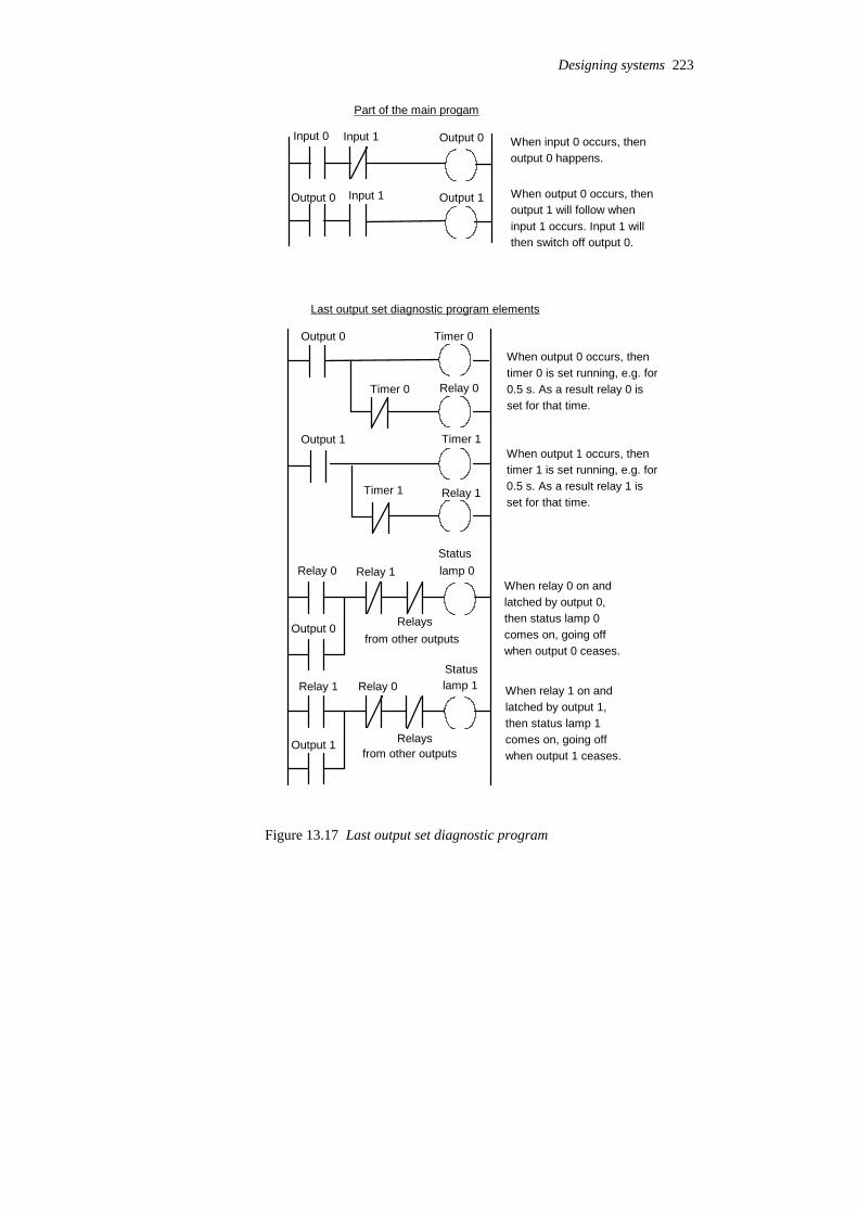
Output 0
Output 1
Input 0
Output 0 Input 1
Part of the main progam
When input 0 occurs, thenoutput 0 happens.
When output 0 occurs, thenoutput 1 will follow wheninput 1 occurs. Input 1 willthen switch off output 0.
Input 1
Last output set diagnostic program elements
Output 0 Timer 0
Timer 0 Relay 0
Output 1 Timer 1
Timer 1 Relay 1
When output 0 occurs, thentimer 0 is set running, e.g. for0.5 s. As a result relay 0 isset for that time.
When output 1 occurs, thentimer 1 is set running, e.g. for0.5 s. As a result relay 1 isset for that time.
Relay 0
Output 0
Relay 1
Relaysfrom other outputs
Status lamp 0
Statuslamp 1Relay 1
Output 1
Relay 0
Relaysfrom other outputs
When relay 0 on andlatched by output 0, then status lamp 0 comes on, going offwhen output 0 ceases.
When relay 1 on andlatched by output 1, then status lamp 1 comes on, going offwhen output 1 ceases.
Figure 13.17 Last output set diagnostic program
Designing systems 223

Status lamp 1
Status lamp 2
Output 1
Output 2
Output 3
Output 4
Output 50
Output 51
Output 52
Output 53
Switch 1
Switch 2etc.
etc.
a
b
c
d
a
b
c
d
Switch 1 in position a indicates output 1, in position b output 2, inposition c output 3, etc.
Switch 2 in position a indicates output 50, in position b output 51, inposition c output 52, etc.
Figure 13.18 Single status lamp for a group of outputs
As an illustration of the use of the program to indicate whichaction occurred last, Figure 13.19 shows the program that might beused with a pneumatic system operating cylinders in a sequence. Theprogram indicates at which point in the sequence a fault occurred, e.g.a piston sticking, and would be added to the main program used tosequence the cylinders. Each of the cylinder movements has alight-emitting diode associated with it, the last cylinder movementbeing indicated by its LED being illuminated.
3 ReplicationWhere there is concern regarding safety in the case of a faultdeveloping, checks may be constantly used to detect faults. Onetechnique is replication checks which involves duplicating, i.e.replicating, the PLC system. This could mean that the system repeatsevery operation twice and if it gets the same result it is assumed thereis no fault. This procedure can detect transient faults. A moreexpensive alternative is to have duplicate PLC systems and comparethe results given by the two systems. In the absence of a fault the tworesults should be the same, a fault showing up as a difference.
224 Programmable Logic Controllers

A+ Timer 1
Timer 1 IR 1
B+ Timer 2
Timer 2 IR 2
C+ Timer 3
Timer 3 IR 3
A– Timer 4
Timer 4 IR 4
B– Timer 5
Timer 5 IR 5
C– Timer 6
Timer 6 IR 6
IR 1 LED A+
LED A+
IR 2 IR 3 IR 4 IR 5 IR 6 Reset
IR 2 IR 1 IR 3 IR 4 IR 5 IR 6 Reset LED B+
LED B+
The output A+ produces ashort duration pulse atIR 1 as a result of thetimer setting
The output B+ produces ashort duration pulse atIR 2 as a result of thetimer setting
The output C+ produces ashort duration pulse atIR 3 as a result of thetimer setting
The output A– produces ashort duration pulse atIR 4 as a result of thetimer setting
The output B– produces ashort duration pulse atIR 5 as a result of thetimer setting
The output C– produces ashort duration pulse atIR 6 as a result of thetimer setting
If A+ output occurs, IR 1 closesand is latched on. LED A+ isthen on. LED A+ is not onunless IR 1 closed
If B+ output occurs, IR 2 closesand is latched on. LED B+ isthen on. LED B+ is not onunless IR 2 closed
Figure 13.19 (Continued on next page)
Designing systems 225
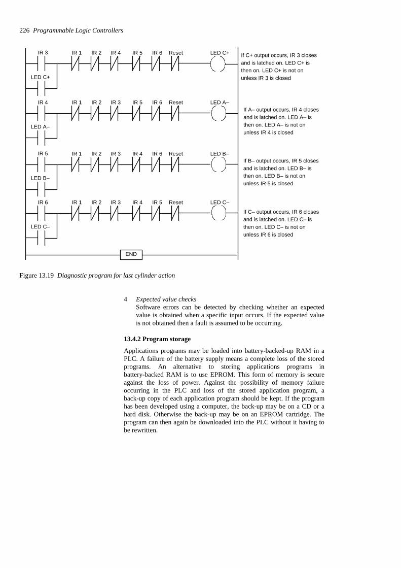
IR 4 IR 1 IR 2 IR 3 IR 5 IR 6 Reset LED A–
LED A–
IR 5 LED B–
LED B–
IR 1 IR 2 IR 3 IR 4 IR 6 Reset
IR 6 IR 1 IR 2 IR 3 IR 4 IR 5 Reset LED C–
LED C–
END
If A– output occurs, IR 4 closesand is latched on. LED A– isthen on. LED A– is not onunless IR 4 is closed
If B– output occurs, IR 5 closesand is latched on. LED B– isthen on. LED B– is not onunless IR 5 is closed
If C– output occurs, IR 6 closesand is latched on. LED C– isthen on. LED C– is not onunless IR 6 is closed
IR 3 LED C+
LED C+
IR 1 IR 2 IR 4 IR 5 IR 6 Reset If C+ output occurs, IR 3 closesand is latched on. LED C+ isthen on. LED C+ is not onunless IR 3 is closed
Figure 13.19 Diagnostic program for last cylinder action
4 Expected value checksSoftware errors can be detected by checking whether an expectedvalue is obtained when a specific input occurs. If the expected valueis not obtained then a fault is assumed to be occurring.
13.4.2 Program storage
Applications programs may be loaded into battery-backed-up RAM in aPLC. A failure of the battery supply means a complete loss of the storedprograms. An alternative to storing applications programs inbattery-backed RAM is to use EPROM. This form of memory is secureagainst the loss of power. Against the possibility of memory failureoccurring in the PLC and loss of the stored application program, aback-up copy of each application program should be kept. If the programhas been developed using a computer, the back-up may be on a CD or ahard disk. Otherwise the back-up may be on an EPROM cartridge. Theprogram can then again be downloaded into the PLC without it having tobe rewritten.
226 Programmable Logic Controllers
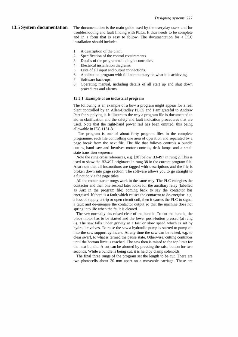
13.5 System documentation The documentation is the main guide used by the everyday users and fortroubleshooting and fault finding with PLCs. It thus needs to be completeand in a form that is easy to follow. The documentation for a PLCinstallation should include:
1 A description of the plant.2 Specification of the control requirements.3 Details of the programmable logic controller.4 Electrical installation diagrams.5 Lists of all input and output connections.6 Application program with full commentary on what it is achieving.7 Software back-ups.8 Operating manual, including details of all start up and shut down
procedures and alarms.
13.5.1 Example of an industrial program
The following is an example of a how a program might appear for a realplant controlled by an Allen-Bradley PLC5 and I am grateful to AndrewParr for supplying it. It illustrates the way a program file is documented toaid in clarification and the safety and fault indication procedures that areused. Note that the right-hand power rail has been omitted, this beingallowable in IEC 1131-3.
The program is one of about forty program files in the completeprogramme, each file controlling one area of operation and separated by apage break from the next file. The file that follows controls a bundlecutting band saw and involves motor controls, desk lamps and a smallstate transition sequence.
Note the rung cross references, e.g. [38] below B3/497 in rung 2. This isused to show the B3/497 originates in rung 38 in the current program file.Also note that all instructions are tagged with descriptions and the file isbroken down into page section. The software allows you to go straight toa function via the page titles.
All the motor starter rungs work in the same way. The PLC energises thecontactor and then one second later looks for the auxiliary relay (labelledas Aux in the program file) coming back to say the contactor hasenergised. If there is a fault which causes the contactor to de-energise, e.g.a loss of supply, a trip or open circuit coil, then it causes the PLC to signala fault and de-energise the contactor output so that the machine does notspring into life when the fault is cleared.
The saw normally sits raised clear of the bundle. To cut the bundle, theblade motor has to be started and the lower push-button pressed (at rung8). The saw falls under gravity at a fast or slow speed which is set byhydraulic valves. To raise the saw a hydraulic pump is started to pump oilinto the saw support cylinders. At any time the saw can be raised, e.g. toclear swarf, to what is termed the pause state. Otherwise, cutting continuesuntil the bottom limit is reached. The saw then is raised to the top limit forthe next bundle. A cut can be aborted by pressing the raise button for twoseconds. While a bundle is being cut, it is held by clamp solenoids.
The final three rungs of the program set the length to be cut. There aretwo photocells about 20 mm apart on a moveable carriage. These are
Designing systems 227
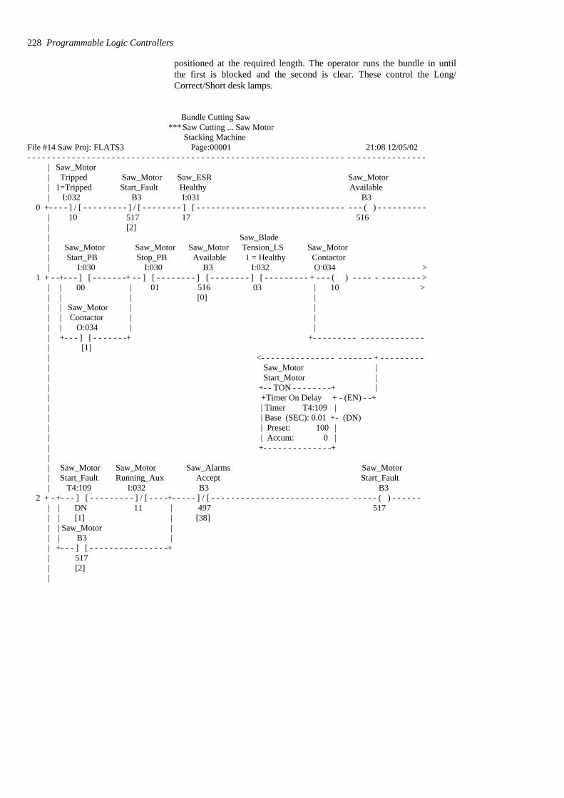
positioned at the required length. The operator runs the bundle in untilthe first is blocked and the second is clear. These control the Long/Correct/Short desk lamps.
Bundle Cutting Saw *** Saw Cutting ... Saw Motor
Stacking Machine File #14 Saw Proj: FLATS3 Page:00001 21:08 12/05/02- - - - - - - - - - - - - - - - - - - - - - - - - - - - - - - - - - - - - - - - - - - - - - - - - - - - - - - - - - - - - - - - - - - - - - - - - - - - - - - -
| Saw_Motor | Tripped Saw_Motor Saw_ESR Saw_Motor | 1=Tripped Start_Fault Healthy Available
| I:032 B3 I:031 B3 0 +- - - - ] / [ - - - - - - - - - ] / [ - - - - - - - - ] [ - - - - - - - - - - - - - - - - - - - - - - - - - - - - - - - - - ( ) - - - - - - - - - -
| 10 517 17 516| [2]| Saw_Blade| Saw_Motor Saw_Motor Saw_Motor Tension_LS Saw_Motor| Start_PB Stop_PB Available 1 = Healthy Contactor| I:030 I:030 B3 I:032 O:034 >
1 + - -+- - - ] [ - - - - - - -+ - - ] [ - - - - - - - - ] [ - - - - - - - - ] [ - - - - - - - - - + - - - ( ) - - - - - - - - - - - - - > | | 00 | 01 516 03 | 10 >| | | [0] || | Saw_Motor | || | Contactor | || | O:034 | || +- - - ] [ - - - - - - -+ +- - - - - - - - - - - - - - - - - - - - - - | [1]| <- - - - - - - - - - - - - - - - - - - - - - + - - - - - - - - -| Saw_Motor || Start_Motor || +- - TON - - - - - - - -+ || +Timer On Delay + - (EN) - -+| | Timer T4:109 || | Base (SEC): 0.01 +- (DN)| | Preset: 100 || | Accum: 0 || +- - - - - - - - - - - - - -+|| Saw_Motor Saw_Motor Saw_Alarms Saw_Motor| Start_Fault Running_Aux Accept Start_Fault| T4:109 I:032 B3 B3
2 + - +- - - ] [ - - - - - - - - - ] / [ - - - -+- - - - - ] / [ - - - - - - - - - - - - - - - - - - - - - - - - - - - - - - - - - ( ) - - - - - - | | DN 11 | 497 517| | [1] | [38]| | Saw_Motor || | B3 || +- - - ] [ - - - - - - - - - - - - - - - -+ | 517| [2]|
228 Programmable Logic Controllers
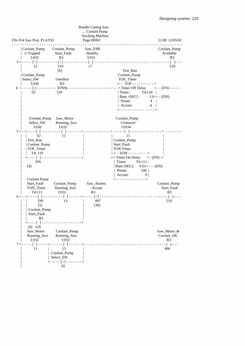
Bundle Cutting Saw ... Coolant Pump Stacking Machine
File #14 Saw Proj: FLATS3 Page:00002 21:08 12/05/02- - - - - - - - - - - - - - - - - - - - - - - - - - - - - - - - - - - - - - - - - - - - - - - - - - - - - - - - - - - - - - - - - - - - - - - - - - - - - - -
| Coolant_Pump Coolant_Pump Saw_ESR Coolant_Pump| 1=Tripped Start_Fault Healthy Available| I:032 B3 I:031 B3
3 +- - - - - ] / [ - - - - - - - - - ] / [ - - - - - - - - - - - ] [ - - - - - - - - - - - - - - - - - - - - - - - - - - - -- - - - - - - ( ) - - - | 12 519 17 518| [6] Test_Run| Coolant_Pump Coolant_Pump| Select_SW OneShot TOF_Timer| I:030 B3 +- - TOF - - - - - - - - - - +
4 +- - - - - ] [ - - - - - - - - - ]ONS[- - - - - - - - - - - - - - - - - - - - - - - + Timer Off Delay +- - (EN) - - - - -| 02 520 | Timer: T4:110 | | | Base (SEC) : 1.0 +- - (DN)| | Preset: 4 | | | Accum: 4 || +- - - - - - - - - - - - - - - - + || Coolant_Pump Saw_Motor Coolant_Pump| Select_SW Running_Aux Contactor| I:030 I:032 O:034
5 +- -+- - - - ] [ - - - - - - - - - ] [ - - - - - - -+ - - - - - - - - - - - - + - - - - - ( ) - - - - - - - - - - - - - - + - - - - - - -- | | 02 11 | | 11 |
| | Test_Run | | Coolant_Pump || | Coolant_Pump | | Start_Fault || | TOF_Timer | | TON Timer || | T4: 110 | | +- - TON - - - - - - - - + || +- - - - ] [ - - - - - - - - - - - - - - - - - - + ++ Timer On Delay + - (EN) -+| DN | Timer: T4:111 || [4] | Base (SEC): 0.01+ - - (DN)| | Preset: 100 || | Accum: 0 || Coolant Pump +- - - - - - - - - - - - - - +
| Start_Fault Coolant_Pump Saw_Alarms Coolant_Pump| TON_Timer Running_Aux Accept Start_Fault| T4:111 I:032 B3 B3
6 + - -+ - - - - ] [ - - - - - - - - - ] [ - - - - - -+ - - - - ] / [ - - - - - - - - - - - - - - - - - - - - - - - - - - -- - - - ( ) - - - | | DN 13 | 497 519| | [5] | [38]| | Coolant_Pump || | Start_Fault || | B3 || +- - - - ] [ - - - - - - - - - - - - - -- - - - -+| [6] 519| Saw_Motor Coolant_Pump Saw_Motor_&| Running_Aux Running_Aux Coolant_OK| I:032 I:032 B3
7 +- - - - - ] [ - - - - + - - - - - - ] [ - - - - - -+ - - - - - - - - - - - - - - - - - - - - - - - - - - - - - - - - - - - - - ( ) - - - | 11 | 13 | 496| | Coolant_Pump || | Select_SW | | +- - - - - ] / [ - - - - - - - +| 02
Designing systems 229

Bundle Cutting Saw ... Coolant Pump Stacking Machine
File #14 Saw Proj: FLATS3 Page:00003 21:08 12/05/02 - - - - - - - - - - - - - - - - - - - - - - - - - - - - - - - - - - - - - - - - - - - - - - - - - - - - - - - - - - - - - - - - - - - - - - - - - - - - - - - - - - - Blank page for future modification
230 Programmable Logic Controllers
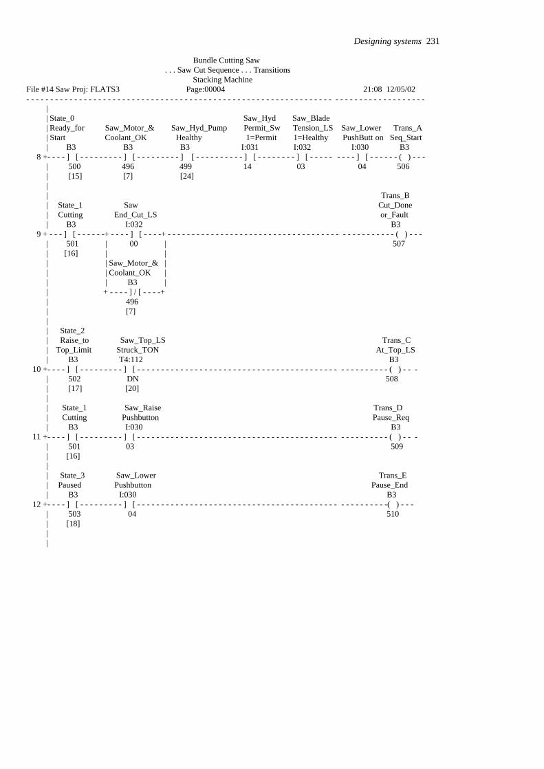
Bundle Cutting Saw . . . Saw Cut Sequence . . . Transitions
Stacking Machine File #14 Saw Proj: FLATS3 Page:00004 21:08 12/05/02- - - - - - - - - - - - - - - - - - - - - - - - - - - - - - - - - - - - - - - - - - - - - - - - - - - - - - - - - - - - - - - - - - - - - - - - - - - - - - - - - - -
|| State_0 Saw_Hyd Saw_Blade| Ready_for Saw_Motor_& Saw_Hyd_Pump Permit_Sw Tension_LS Saw_Lower Trans_A| Start Coolant_OK Healthy 1=Permit 1=Healthy PushButt on Seq_Start| B3 B3 B3 I:031 I:032 I:030 B3
8 +- - - - ] [ - - - - - - - - - ] [ - - - - - - - - - ] [ - - - - - - - - - - ] [ - - - - - - - - ] [ - - - - - - - - - ] [ - - - - - - ( ) - - -| 500 496 499 14 03 04 506| [15] [7] [24] || Trans_B| State_1 Saw Cut_Done| Cutting End_Cut_LS or_Fault| B3 I:032 B3
9 + - - - ] [ - - - - - -+ - - - - ] [ - - - -+ - - - - - - - - - - - - - - - - - - - - - - - - - - - - - - - - - - - - - - - - - - - - - - - ( ) - - - | 501 | 00 | 507| [16] | || | Saw_Motor_& || | Coolant_OK || | B3 || + - - - - ] / [ - - - -+| 496| [7]|| State_2| Raise_to Saw_Top_LS Trans_C| Top_Limit Struck_TON At_Top_LS| B3 T4:112 B3
10 +- - - - ] [ - - - - - - - - - ] [ - - - - - - - - - - - - - - - - - - - - - - - - - - - - - - - - - - - - - - - - - - - - - - - - - - - - ( ) - - -| 502 DN 508| [17] [20]|| State_1 Saw_Raise Trans_D| Cutting Pushbutton Pause_Req| B3 I:030 B3
11 +- - - - ] [ - - - - - - - - - ] [ - - - - - - - - - - - - - - - - - - - - - - - - - - - - - - - - - - - - - - - - - - - - - - - - - - - - ( ) - - -| 501 03 509| [16]|| State_3 Saw_Lower Trans_E| Paused Pushbutton Pause_End| B3 I:030 B3
12 +- - - - ] [ - - - - - - - - - ] [ - - - - - - - - - - - - - - - - - - - - - - - - - - - - - - - - - - - - - - - - - - - - - - - - - - - -( ) - - -| 503 04 510| [18]||
Designing systems 231
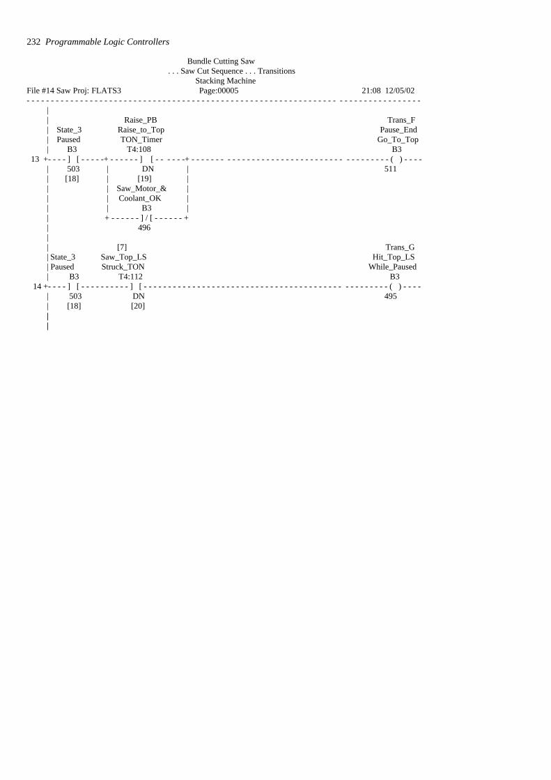
Bundle Cutting Saw . . . Saw Cut Sequence . . . Transitions
Stacking Machine File #14 Saw Proj: FLATS3 Page:00005 21:08 12/05/02- - - - - - - - - - - - - - - - - - - - - - - - - - - - - - - - - - - - - - - - - - - - - - - - - - - - - - - - - - - - - - - - - - - - - - - - - - - - - - - - -
|| Raise_PB Trans_F| State_3 Raise_to_Top Pause_End| Paused TON_Timer Go_To_Top| B3 T4:108 B3
13 +- - - - ] [ - - - - -+ - - - - - - ] [ - - - - - -+ - - - - - - - - - - - - - - - - - - - - - - - - - - - - - - - - - - - - - - - - ( ) - - - -| 503 | DN | 511| [18] | [19] |
| | Saw_Motor_& || | Coolant_OK || | B3 || + - - - - - - ] / [ - - - - - - +| 496|| [7] Trans_G| State_3 Saw_Top_LS Hit_Top_LS| Paused Struck_TON While_Paused| B3 T4:112 B3
14 +- - - - ] [ - - - - - - - - - - ] [ - - - - - - - - - - - - - - - - - - - - - - - - - - - - - - - - - - - - - - - - - - - - - - - - - - ( ) - - - -| 503 DN 495| [18] [20]||
232 Programmable Logic Controllers
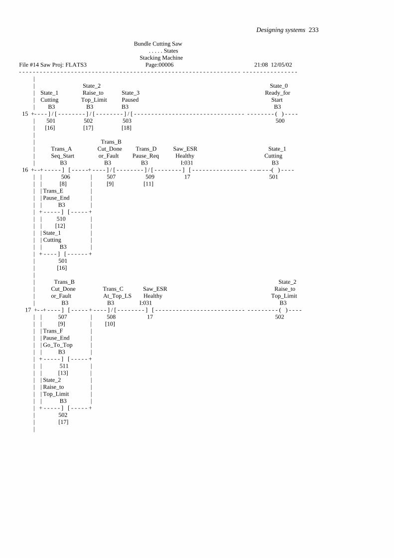
Bundle Cutting Saw . . . . . States
Stacking Machine File #14 Saw Proj: FLATS3 Page:00006 21:08 12/05/02- - - - - - - - - - - - - - - - - - - - - - - - - - - - - - - - - - - - - - - - - - - - - - - - - - - - - - - - - - - - - - - - - - - - - - - - - - - - - - - -
|| State_2 State_0| State_1 Raise_to State_3 Ready_for| Cutting Top_Limit Paused Start| B3 B3 B3 B3
15 +- - - - ] / [ - - - - - - - - ] / [ - - - - - - - - ] / [ - - - - - - - - - - - - - - - - - - - - - - - - - - - - - - - - - - - - - - - - ( ) - - - -| 501 502 503 500| [16] [17] [18]|| Trans_B| Trans_A Cut_Done Trans_D Saw_ESR State_1| Seq_Start or_Fault Pause_Req Healthy Cutting | B3 B3 B3 I:031 B3
16 +- -+ - - - - - ] [ - - - - -+ - - - - ] / [ - - - - - - - - ] / [ - - - - - - - - ] [ - - - - - - - - - - - - - - - - - - -- - - -( ) - - - -| | 506 | 507 509 17 501| | [8] | [9] [11]| | Trans_E || | Pause_End || | B3 || + - - - - - ] [ - - - - - +| | 510 || | [12] | | | State_1 || | Cutting || | B3 || + - - - - ] [ - - - - - - +| 501| [16]|| Trans_B State_2| Cut_Done Trans_C Saw_ESR Raise_to| or_Fault At_Top_LS Healthy Top_Limit | B3 B3 I:031 B3
17 +- -+ - - - - ] [ - - - - - + - - - - ] / [ - - - - - - - - ] [ - - - - - - - - - - - - - - - - - - - - - - - - - - - - - - - - - - - ( ) - - - -| | 507 | 508 17 502
| | [9] | [10] | | Trans_F || | Pause_End || | Go_To_Top || | B3 || + - - - - - ] [ - - - - - +| | 511 || | [13] | | | State_2 || | Raise_to || | Top_Limit || | B3 || + - - - - - ] [ - - - - - +| 502| [17]|
Designing systems 233

Bundle Cutting Saw . . . . . States
Stacking Machine File #14 Saw Proj: FLATS3 Page:00007 21:08 12/05/02- - - - - - - - - - - - - - - - - - - - - - - - - - - - - - - - - - - - - - - - - - - - - - - - - - - - - - - - - - - - - - - - - - - - - - - - - - - - - - - -
|| Trans_F Trans_G | Trans_D Trans_E Pause_End Hit_Top_LS Saw_ESR State_3| Pause_Req Pause_End Go_To_Top while_Paused Healthy Paused| B3 B3 B3 B3 I:031 B3
18 +- + - - ] [ - - - - + - - - - ] / [ - - - - - - - - - ] / [ - - - - - - - - - - ] / [ - - - - - - - - ] [ - - - - - - - - - - -- - - ( ) - - -| | 509 | 510 511 495 17 503| | [11] || | State_3 || | Paused || | B3 || + - - ] [ - - - -+| 503| [18]||
234 Programmable Logic Controllers
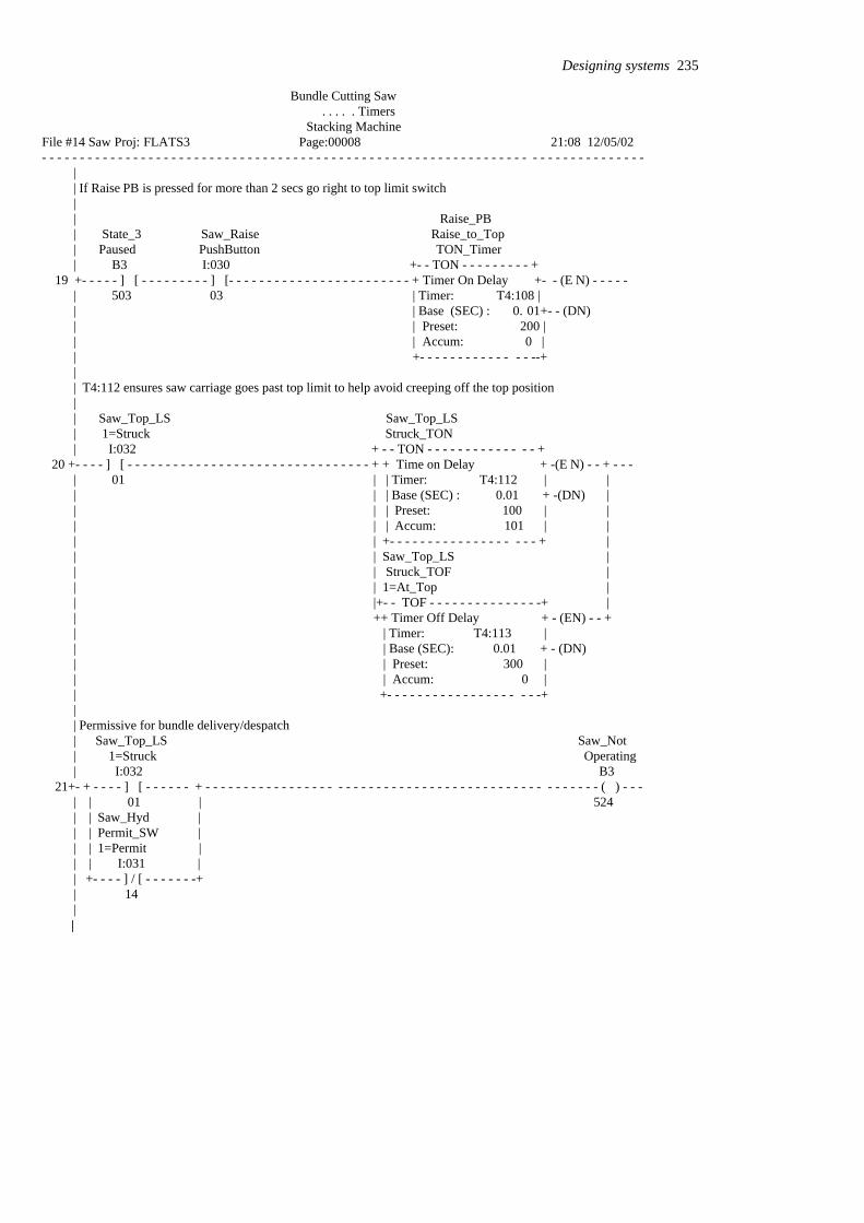
Bundle Cutting Saw . . . . . Timers
Stacking Machine File #14 Saw Proj: FLATS3 Page:00008 21:08 12/05/02- - - - - - - - - - - - - - - - - - - - - - - - - - - - - - - - - - - - - - - - - - - - - - - - - - - - - - - - - - - - - - - - - - - - - - - - - - - - - - -
|| If Raise PB is pressed for more than 2 secs go right to top limit switch|| Raise_PB| State_3 Saw_Raise Raise_to_Top| Paused PushButton TON_Timer| B3 I:030 +- - TON - - - - - - - - - +
19 +- - - - - ] [ - - - - - - - - - ] [- - - - - - - - - - - - - - - - - - - - - - - - + Timer On Delay +- - (E N) - - - - -| 503 03 | Timer: T4:108 | | | Base (SEC) : 0. 01+- - (DN)| | Preset: 200 | | | Accum: 0 || +- - - - - - - - - - - - - - --+|| T4:112 ensures saw carriage goes past top limit to help avoid creeping off the top position|| Saw_Top_LS Saw_Top_LS| 1=Struck Struck_TON| I:032 + - - TON - - - - - - - - - - - - - - +
20 +- - - - ] [ - - - - - - - - - - - - - - - - - - - - - - - - - - - - - - - - + + Time on Delay + -(E N) - - + - - -| 01 | | Timer: T4:112 | || | | Base (SEC) : 0.01 + -(DN) | | | | Preset: 100 | || | | Accum: 101 | || | +- - - - - - - - - - - - - - - - - - - + || | Saw_Top_LS || | Struck_TOF || | 1=At_Top || |+- - TOF - - - - - - - - - - - - - - -+ || ++ Timer Off Delay + - (EN) - - +| | Timer: T4:113 || | Base (SEC): 0.01 + - (DN)| | Preset: 300 || | Accum: 0 || +- - - - - - - - - - - - - - - - - - - -+|| Permissive for bundle delivery/despatch
| Saw_Top_LS Saw_Not| 1=Struck Operating| I:032 B3
21+- + - - - - ] [ - - - - - - + - - - - - - - - - - - - - - - - - - - - - - - - - - - - - - - - - - - - - - - - - - - - - - - - - - - ( ) - - - | | 01 | 524| | Saw_Hyd | | | Permit_SW || | 1=Permit || | I:031 || +- - - - ] / [ - - - - - - -+| 14
| |
Designing systems 235
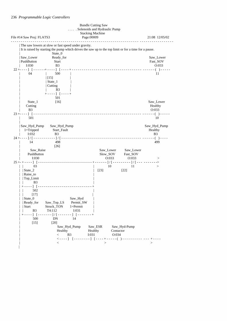
Bundle Cutting Saw . . . . . Solenoids and Hydraulic Pump
Stacking Machine File #14 Saw Proj: FLATS3 Page:00009 21:08 12/05/02- - - - - - - - - - - - - - - - - - - - - - - - - - - - - - - - - - - - - - - - - - - - - - - - - - - - - - - - - - - - - - - - - - - - - - - - - - - - - - - - -
| The saw lowers at slow or fast speed under gravity.| It is raised by starting the pump which drives the saw up to the top limit or for a time for a pause.| State_0| Saw_Lower Ready_for Saw_Lower| PushButton Start Fast_SOV| I:030 B3 O:033
22 +- - - - ] [ - - - - - -+ - - - - ] [ - - - - + - - - - - - - - - - - - - - - - - - - - - - - - - - - - - - - - - - - - - - - - - ( ) - - - - -| 04 | 500 | 11| | [15] || | State_1 || | Cutting || | B3 || + - - - - ] [ - - - - +| 501| State_1 [16] Saw_Lower| Cutting Healthy| B3 O:033
23 +- - - - ] [ - - - - - - - - - - - - - - - - - - - - - - - - - - - - - - - - - - - - - - - - - - - - - - - - - - - - - - - - - - - - ( ) - - - - -| 501 10|| Saw_Hyd_Pump Saw_Hyd_Pump Saw_Hyd_Pump| 1=Tripped Start_Fault Healthy| I:032 B3 B3
24 +- - - - ] / [ - - - - - - - - - - - ] / [ - - - - - - - - - - - - - - - - - - - - - - - - - - - - - - - - - - - - - - - - - - - - - - ( ) - - - -| 14 498 499| [26]| Saw_Raise Saw_Lower Saw_Lower| PushButton Slow_SOV Fast_SOV| I:030 O:033 O:033 >
25 +- + - - - - ] [ - - - - - - - - - - - - - - - - - - - - - - - - - - - + - - - - - - ] / [ - - - - - - - - - ] / [ - - - - - - - - - ->| | 03 | 10 11 >| | State_2 | [23] [22]| | Raise_to || | Top_Limit || | B3 || + - - - - ] [ - - - - - - - - - - - - - - - - - - - - - - - - - - - +| | 502 || | [17] || | State_0 Saw_Hyd || | Ready_for Saw_Top_LS Permit_SW || | Start Struck_TON 1=Permit || | B3 T4:112 I:031 || + - - - - ] [ - - - - - - - ] / [ - - - - - - - ] [ - - - - - - - +| 500 DN 14| [15] [20]| Saw_Hyd_Pump Saw_ESR Saw_Hyd-Pump| Healthy Healthy Contactor | < B3 I:031 O:034| < - - - - ] [ - - - - - - - - ] [ - - - - + - - - - - ( ) - - - - - - - - - - - - - + - - - -| < > >
|
236 Programmable Logic Controllers

Bundle Cutting Saw . . . . . Solenoids and Hydraulic Pump
Stacking Machine File #14 Saw Proj: FLATS3 Page:00010 21:08 12/05/02- - - - - - - - - - - - - - - - - - - - - - - - - - - - - - - - - - - - - - - - - - - - - - - - - - - - - - - - - - - - - - - - - - - - - - - - - - - - - - - - - -
| < > >| < 499 17 | 12 || | || | Saw_Hyd_Pump || | Start_Fault || | TON_Timer || |+ - - TON - - - - - - - - - - + || ++ Timer On Delay + - (EN )- +| | Timer: T4:114 || | Base (SEC) : 0.01 +- (DN)| | Preset: 100 || | Accum: 0 || + - - - - - - - - - - - - - - -+|| Saw_Hyd_Pump
| Start_Fault Saw_Hyd_Pump Saw_Alarms Saw_Hyd_Pump| TON_Timer Running_Aux Accept Start_Fault| T4:114 I:032 B3 B3
26 +- + - - - - ] [ - - - - - - - - - ] / [ - - - - - - -+ - - - - ] / [ - - - - - - - - - - - - - - - - - - - - - - - - - - - - - - - - - - ( ) - - - | | DN 15 | 497 498| | [25] | [38]| | Saw_Hyd_Pump || | Start_Fault || | B3 || +- - - - ] [ - - - - - - - - - - - - - -- - - - - +| 498| [26]|
Designing systems 237
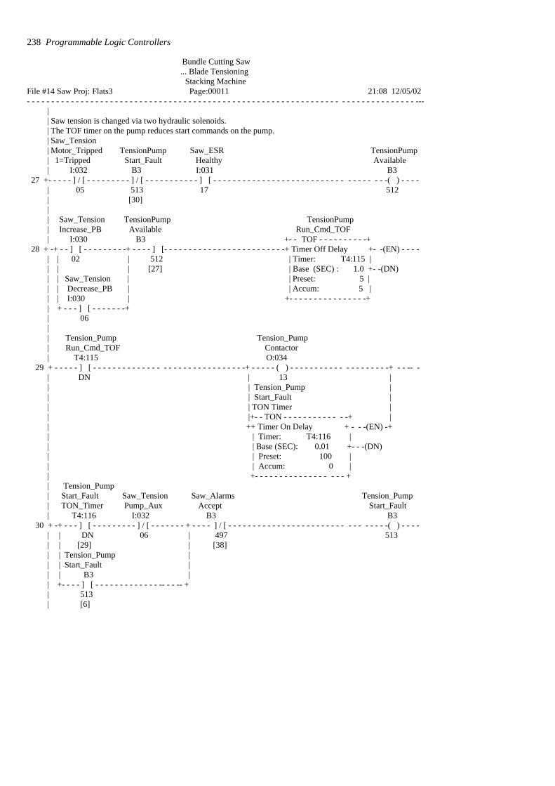
Bundle Cutting Saw ... Blade Tensioning
Stacking Machine File #14 Saw Proj: Flats3 Page:00011 21:08 12/05/02- - - - - - - - - - - - - - - - - - - - - - - - - - - - - - - - - - - - - - - - - - - - - - - - - - - - - - - - - - - - - - - - - - - - - - - - - - - - - - - ---
|| Saw tension is changed via two hydraulic solenoids.| The TOF timer on the pump reduces start commands on the pump.| Saw_Tension| Motor_Tripped TensionPump Saw_ESR TensionPump| 1=Tripped Start_Fault Healthy Available| I:032 B3 I:031 B3
27 +- - - - - ] / [ - - - - - - - - - ] / [ - - - - - - - - - - - ] [ - - - - - - - - - - - - - - - - - - - - - - - - - - - - - - - - - - -( ) - - - -| 05 513 17 512| [30] || Saw_Tension TensionPump TensionPump| Increase_PB Available Run_Cmd_TOF| I:030 B3 +- - TOF - - - - - - - - - -+
28 + -+ - - ] [ - - - - - - - - -+ - - - - ] [- - - - - - - - - - - - - - - - - - - - - - - - -+ Timer Off Delay +- -(EN) - - - -| | 02 | 512 | Timer: T4:115 | | | | [27] | Base (SEC) : 1.0 +- -(DN)| | Saw_Tension | | Preset: 5 | | | Decrease_PB | | Accum: 5 || | I:030 | +- - - - - - - - - - - - - - - -+| + - - - ] [ - - - - - - -+| 06|| Tension_Pump Tension_Pump| Run_Cmd_TOF Contactor| T4:115 O:034
29 + - - - - - ] [ - - - - - - - - - - - - - - - - - - - - - - - - - - - - - - -+ - - - - - ( ) - - - - - - - - - - - - - - - - - - - -+ - - -- -| DN | 13 || | Tension_Pump || | Start_Fault || | TON Timer || |+- - TON - - - - - - - - - - - - -+ || ++ Timer On Delay + - - -(EN) -+| | Timer: T4:116 || | Base (SEC): 0.01 +- - -(DN)| | Preset: 100 || | Accum: 0 || +- - - - - - - - - - - - - - - - - - +| Tension_Pump
| Start_Fault Saw_Tension Saw_Alarms Tension_Pump| TON_Timer Pump_Aux Accept Start_Fault| T4:116 I:032 B3 B3
30 + -+ - - - ] [ - - - - - - - - - ] / [ - - - - - - - + - - - - ] / [ - - - - - - - - - - - - - - - - - - - - - - - - - - - - - - - -( ) - - - - | | DN 06 | 497 513| | [29] | [38]| | Tension_Pump || | Start_Fault || | B3 || +- - - - ] [ - - - - - - - - - - - - - -- - - -- +| 513| [6]
238 Programmable Logic Controllers
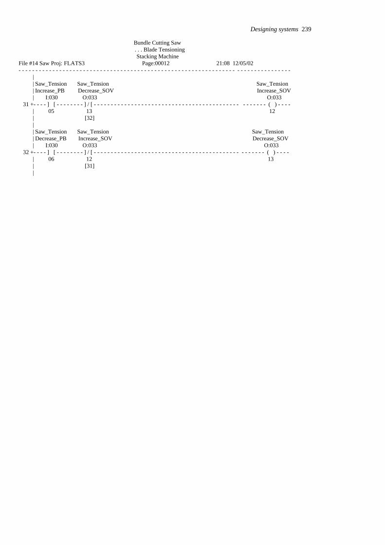
Bundle Cutting Saw . . . Blade Tensioning Stacking Machine
File #14 Saw Proj: FLATS3 Page:00012 21:08 12/05/02- - - - - - - - - - - - - - - - - - - - - - - - - - - - - - - - - - - - - - - - - - - - - - - - - - - - - - - - - - - - - - - - - - - - - - - - - - - - - - - -
|| Saw_Tension Saw_Tension Saw_Tension| Increase_PB Decrease_SOV Increase_SOV| I:030 O:033 O:033
31 +- - - - ] [ - - - - - - - - ] / [ - - - - - - - - - - - - - - - - - - - - - - - - - - - - - - - - - - - - - - - - - - - - - - - - - - ( ) - - - -| 05 13 12| [32]|| Saw_Tension Saw_Tension Saw_Tension| Decrease_PB Increase_SOV Decrease_SOV| I:030 O:033 O:033
32 +- - - - ] [ - - - - - - - - ] / [ - - - - - - - - - - - - - - - - - - - - - - - - - - - - - - - - - - - - - - - - - - - - - - - - - - ( ) - - - -| 06 12 13| [31]|
Designing systems 239
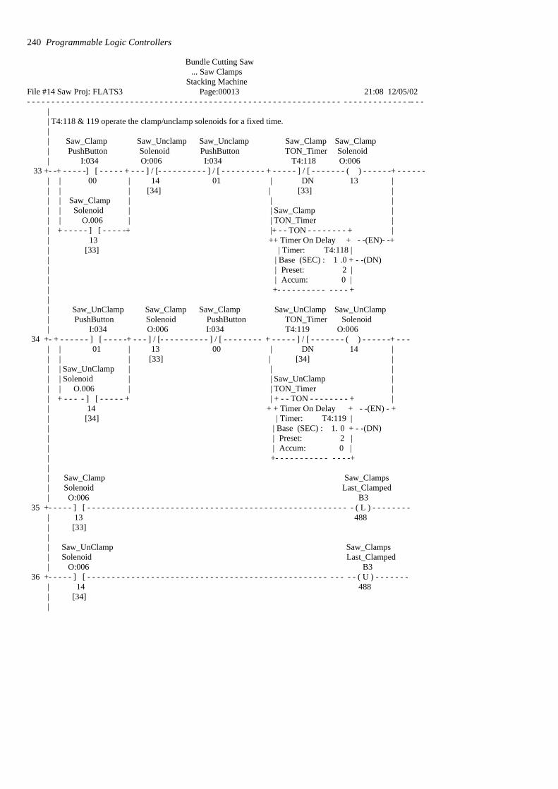
Bundle Cutting Saw ... Saw Clamps
Stacking Machine File #14 Saw Proj: FLATS3 Page:00013 21:08 12/05/02- - - - - - - - - - - - - - - - - - - - - - - - - - - - - - - - - - - - - - - - - - - - - - - - - - - - - - - - - - - - - - - - - - - - - - - - - - - - - -- - -
|| T4:118 & 119 operate the clamp/unclamp solenoids for a fixed time.|| Saw_Clamp Saw_Unclamp Saw_Unclamp Saw_Clamp Saw_Clamp| PushButton Solenoid PushButton TON_Timer Solenoid| I:034 O:006 I:034 T4:118 O:006
33 +- -+ - - - - -] [ - - - - - + - - - ] / [- - - - - - - - - - ] / [ - - - - - - - - - + - - - - - ] / [ - - - - - - - ( ) - - - - - -+ - - - - - -| | 00 | 14 01 | DN 13 || | | [34] | [33] | | | Saw_Clamp | | || | Solenoid | | Saw_Clamp || | O.006 | | TON_Timer || + - - - - - ] [ - - - - -+ |+ - - TON - - - - - - - - + || 13 ++ Timer On Delay + - -(EN)- -+ | [33] | Timer: T4:118 | | | Base (SEC) : 1 .0 + - -(DN)| | Preset: 2 | | | Accum: 0 || +- - - - - - - - - - - - - - +|| Saw_UnClamp Saw_Clamp Saw_Clamp Saw_UnClamp Saw_UnClamp| PushButton Solenoid PushButton TON_Timer Solenoid| I:034 O:006 I:034 T4:119 O:006
34 +- + - - - - - - ] [ - - - - -+ - - - ] / [- - - - - - - - - - ] / [ - - - - - - - - + - - - - - ] / [ - - - - - - - ( ) - - - - - -+ - - -| | 01 | 13 00 | DN 14 || | | [33] | [34] | | | Saw_UnClamp | | || | Solenoid | | Saw_UnClamp || | O.006 | | TON_Timer || + - - - - ] [ - - - - - + | + - - TON - - - - - - - - + || 14 + + Timer On Delay + - -(EN) - + | [34] | Timer: T4:119 | | | Base (SEC) : 1. 0 + - -(DN)| | Preset: 2 | | | Accum: 0 || +- - - - - - - - - - - - - - -+|| Saw_Clamp Saw_Clamps| Solenoid Last_Clamped| O:006 B3
35 +- - - - - ] [ - - - - - - - - - - - - - - - - - - - - - - - - - - - - - - - - - - - - - - - - - - - - - - - - - - - - - - ( L ) - - - - - - - -| 13 488| [33]|| Saw_UnClamp Saw_Clamps| Solenoid Last_Clamped| O:006 B3
36 +- - - - - ] [ - - - - - - - - - - - - - - - - - - - - - - - - - - - - - - - - - - - - - - - - - - - - - - - - - - - - - - ( U ) - - - - - - -| 14 488| [34]|
240 Programmable Logic Controllers

Bundle Cutting Saw . . . Saw Clamps
Stacking Machine File #14 Saw Proj: FLATS3 Page:00014 21:08 12/05/02- - - - - - - - - - - - - - - - - - - - - - - - - - - - - - - - - - - - - - - - - - - - - - - - - - - - - - - - - - - - - - - - - - - - - - - - - - - - - - -- - -
|| Saw_Clamp| Saw_Clamps Loading_Valve| Solenoid Required| 0.006 B3
37 +- -+ - - - - ] [ - - - - - - + - - - - - - - - - - - - - - - - - - - - - - - - - - - - - - - - - - - - - - - - - - - - - - - - - - - - - ( ) - - -| | 13 | 48 1| | [33] || | Saw_UnClamp || | Solenoid || | O:006 || + - - - - ] [ - - - - - -+| 14| [34]|| Disch_Desk| Lamp_Test Saw_Alarms| PushButton Accept| I:031 B3
38 +- - - - ] [ - - - - - - - - - - - - - - - - - - - - - - - - - - - - - - - - - - - - - - - - - - - - - - - - - - - - - - - - - - - - - - ( ) - - - - -| 12 497||
Designing systems 241
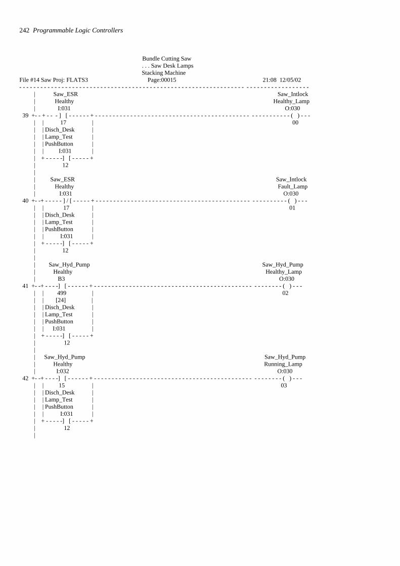
Bundle Cutting Saw . . . Saw Desk Lamps Stacking Machine
File #14 Saw Proj: FLATS3 Page:00015 21:08 12/05/02- - - - - - - - - - - - - - - - - - - - - - - - - - - - - - - - - - - - - - - - - - - - - - - - - - - - - - - - - - - - - - - - - - - - - - - - - - - - - - - - - -
| Saw_ESR Saw_Intlock| Healthy Healthy_Lamp| I:031 O:030
39 +- - + - - - ] [ - - - - - - + - - - - - - - - - - - - - - - - - - - - - - - - - - - - - - - - - - - - - - - - - - - - - - - - - - - - - - - ( ) - - -| | 17 | 00| | Disch_Desk || | Lamp_Test || | PushButton || | I:031 || + - - - - -] [ - - - - - +| 12|| Saw_ESR Saw_Intlock| Healthy Fault_Lamp| I:031 O:030
40 +- -+ - - - - - ] / [ - - - - - + - - - - - - - - - - - - - - - - - - - - - - - - - - - - - - - - - - - - - - - - - - - - - - - - - - - - - - ( ) - - -| | 17 | 01| | Disch_Desk || | Lamp_Test || | PushButton || | I:031 || + - - - - -] [ - - - - - +| 12|| Saw_Hyd_Pump Saw_Hyd_Pump| Healthy Healthy_Lamp| B3 O:030
41 +- -+ - - - -] [ - - - - - - + - - - - - - - - - - - - - - - - - - - - - - - - - - - - - - - - - - - - - - - - - - - - - - - - - - - - - ( ) - - -| | 499 | 02| | [24] || | Disch_Desk || | Lamp_Test || | PushButton || | I:031 || + - - - - -] [ - - - - - +| 12|| Saw_Hyd_Pump Saw_Hyd_Pump| Healthy Running_Lamp| I:032 O:030
42 +- -+ - - - -] [ - - - - - - + - - - - - - - - - - - - - - - - - - - - - - - - - - - - - - - - - - - - - - - - - - - - - - - - - - - - - ( ) - - -| | 15 | 03| | Disch_Desk || | Lamp_Test || | PushButton || | I:031 || + - - - - -] [ - - - - - +| 12|
242 Programmable Logic Controllers

Bundle Cutting Saw . . . Saw Desk Lamps Stacking Machine
File #14 Saw Proj: FLATS3 Page:00016 21:08 12/05/02- - - - - - - - - - - - - - - - - - - - - - - - - - - - - - - - - - - - - - - - - - - - - - - - - - - - - - - - - - - - - - - - - - - - - - - - - - - - - - -
| Saw_Motor| Saw_Motor Healthy| Available Desk_Lamp| B3 O:030
43 +- -+ - - - -] [ - - - - - - + - - - - - - - - - - - - - - - - - - - - - - - - - - - - - - - - - - - - - - - - - - - - - - - - - - ( ) - - - - -| | 516 | 04| | [0] || | Disch_Desk || | Lamp_Test || | PushButton || | I:031 || + - - - - ] [ - - - - - -+| 12| Saw_Motor| Saw_Motor Saw_Intlock| Running_Aux Desk_Lamp| I:032 O:030
44 +- -+ - - - -] [ - - - - - - + - - - - - - - - - - - - - - - - - - - - - - - - - - - - - - - - - - - - - - - - - - - - - - - - - ( ) - - - - -| | 11 | 05| | Disch_Desk || | Lamp_Test || | PushButton || | I:031 || + - - - - -] [ - - - - - +| 12|| Coolant_Pump Coolant_Pump| Available Healthy_Lamp| B3 O:030
45 +- -+ - - - -] [ - - - - - - + - - - - - - - - - - - - - - - - - - - - - - - - - - - - - - - - - - - - - - - - - - - - - - - - - - - ( ) - - - -| | 518 | 06| | [3] || | Disch_Desk || | Lamp_Test || | PushButton || | I:031 || + - - - - -] [ - - - - - +| 12|| Coolant_Pump Saw_Hyd_Pump| Running_Aux Running_Lamp| I:032 O:030
46 +- -+ - - - -] [ - - - - - - + - - - - - - - - - - - - - - - - - - - - - - - - - - - - - - - - - - - - - - - - - - - - - - - - - - - ( ) - - - - | | 13 | 07| | Disch_Desk || | Lamp_Test || | PushButton || | I:031 || + - - - - -] [ - - - - - +| 12|
Designing systems 243
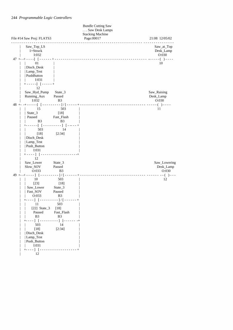
Bundle Cutting Saw . . . Saw Desk Lamps Stacking Machine
File #14 Saw Proj: FLATS3 Page:00017 21:08 12/05/02- - - - - - - - - - - - - - - - - - - - - - - - - - - - - - - - - - - - - - - - - - - - - - - - - - - - - - - - - - - - - - - - - - - - - - - - - - - - - - -
| Saw_Top_LS Saw_at_Top| 1=Struck Desk_Lamp| I:032 O:030
47 +- -+ - - - -] [ - - - - - - + - - - - - - - - - - - - - - - - - - - - - - - - - - - - - - - - - - - - - - - - - - - - - -- - - - - ( ) - - - -| | 01 | 10| | Disch_Desk || | Lamp_Test || | PushButton || | I:031 || + - - - - -] [ - - - - - +| 12| Saw_Hyd_Pump State_3 Saw_Raising| Running_Aux Passed Desk_Lamp| I:032 B3 O:030
48 +- -+ - - - - -] [ - - - - - - - - - ] / [ - - - - - + - - - - - - - - - - - - - - - - - - - - - - - - - - - - - - - - - - - - - ( ) - - - - | | 15 503 | 11| | State_3 [18] || | Paused Fast_Flash || | B3 B3 || +- - - - - -] [ - - - - - - - - - ] [ - -- - - +| | 503 14 || | [18] [2:34] || | Disch_Desk || | Lamp_Test || | Push_Button || | I:031 || + - - - - ] [ - - - - - - - - - - - - - - - - - -+| 12| Saw_Lower State_3 Saw_Lowering| Slow_SOV Passed Desk_Lamp| O:033 B3 O:030
49 +- -+ - - - - ] [ - - - - - - - - - ] / [ - - - - - - + - - - - - - - - - - - - - - - - - - - - - - - - - - - - - - - - - - - - - - - - ( ) - - - | | 10 503 | 12| | [23] [18] | | | Saw_Lower State_3 || | Fast_SOV Paused || | O:033 B3 || +- - - - ] [ - - - - - - - - - ] / [ - - - - - - +| | 11 503 || | [22] State_3 [18] || | Paused Fast_Flash || | B3 B3 || +- - - - ] [ - - - - - - - - - ] [- - - - - - -+| | 503 14 || | [18] [2:34] |
| | Disch_Desk || | Lamp_Test || | Push_Button || | I:031 || +- - - - ] [ - - - - - - - - - - - - - - - - - - +| 12
244 Programmable Logic Controllers

Bundle Cutting Saw . . . Saw Desk Lamps Stacking Machine
File #14 Saw Proj: FLATS3 Page:00018 21:08 12/05/02- - - - - - - - - - - - - - - - - - - - - - - - - - - - - - - - - - - - - - - - - - - - - - - - - - - - - - - - - - - - - - - - - - - - - - - - - - - - - - - -
| State_2| Raise_to End_Cut| Top_Limit Desk_Lamp| B3 O:030
50 +- -+ - - - -] [ - - - - - - + - - - - - - - - - - - - - - - - - - - - - - - - - - - - - - - - - - - - - - - - - - - - - - - - - - ( ) - - - -| | 502 | 13| | [17] || | Disch_Desk || | Lamp_Test || | PushButton || | I:031 || + - - -- - ] [ - - - - - +| 12|| Saw_Blade Saw_Blade| Tension_LS Tension_OK| 1=Healthy Desk_Lamp| I:032 O:030
51 +- -+ - - - - ] [ - - - - - - + - - - - - - - - - - - - - - - - - - - - - - - - - - - - - - - - - - - - - - - - - - - - - - - - - ( ) - - - - -| | 03 | 14| | Disch_Desk || | Lamp_Test || | PushButton || | I:031 || + - - - - ] [ - - - - - -+| 12| Tension_Pump| Saw_Tension Run ning| Pump_Aux Desk_Lamp| I:032 O:030
52 +- -+ - - - -] [ - - - - - - + - - - - - - - - - - - - - - - - - - - - - - - - - - - - - - - - - - - - - - - - - - - - - - - - - - ( ) - - - --| | 06 | 15| | Disch_Desk || | Lamp_Test || | PushButton || | I:031 || + - - - - -] [ - - - - - +| 12| Bundle| Saw_Clamps Clamped| Last_Clamped Desk_Lamp| B3 O:031
53 +- -+ - - - - ] [ - - - - - -+ - - - - - - - - - - - - - - - - - - - - - - - - - - - - - - - - - - - - - - - - - - - - - - - - - - ( ) - - - - -| | 488 | 10| | [36] || | Disch_Desk || | Lamp_Test || | PushButton || | I:031 || + - - - - -] [ - - - - - +| 12
Designing systems 245

Bundle Cutting Saw . . . Saw Desk Lamps Stacking Machine
File #14 Saw Proj: FLATS3 Page:00019 21:08 12/05/02- - - - - - - - - - - - - - - - - - - - - - - - - - - - - - - - - - - - - - - - - - - - - - - - - - - - - - - - - - - - - - - - - - - - - - - - - - - - - - -
|| Bundle| Saw_Clamps UnClamped| Raised_LS Desk_Lamp| O:034 O:031
54 +- - + - - - - - ] [ - - - - - - - - - - - - - - - - -+ - - - - - - - - - - - - - - - - - - - - - - - - - - - - - - - - - - - - - - - ( ) - - - -| | 10 | 11| | Saw_Clamps || | Last_Clamped || | B3 || +- - - - - ] / [ - - - - - - - - - - - - - - - - - +| | 488 || | [36] || | Saw_Unclamp || | Solenoid Fast_Flash || | O:006 B3 || +- - - - - -] [ - - - - - - - - - ] [- - - - - +| | 14 14 || | [34] [2:34] |
| | Disch_Desk || | Lamp_Test || | Push_Button || | I:031 || +- - - - - -] [ - - - - - - - - - - - - - - - - -+| 12||
246 Programmable Logic Controllers

Bundle Cutting Saw . . . Saw Cutting Length Lamps (from PECs)
Stacking Machine File #14 Saw Proj: FLATS3 Page:00020 21:08 12/05/02- - - - - - - - - - - - - - - - - - - - - - - - - - - - - - - - - - - - - - - - - - - - - - - - - - - - - - - - - - - - - - - - - - - - - - - - - - - - - - - - -
|| PECs (photocells) operate at +/– 10 mm from set length|
| West_Saw_Cut East_Saw_Cut | Photocell Photocell Length_Short| 1=Mat_Present 1-Mat_Present Desk_Lamp| I:054 I:054 O:031
55 +- - + - - - - ] / [ - - - - - - - - - ] / [ - - - - - + - - - - - - - - - - - - - - - - - - - - - - - - - - - - - - - - - - - - - - - ( ) - - - - - | | 01 02 | 13| | Disch_Desk || | Lamp_Test || | PushButton || | I:031 || +- - - - ] [ - - - - - - - - - - - - - -- - - - - | 12|
| West_Saw_Cut East_Saw_Cut | Photocell Photocell Length_Correct| 1=Mat_Present 1-Mat_Present Desk_Lamp| I:054 I:054 O:031
56 +- -+ - - - - ] [ - - - - - - - - - ] / [ - - - - - - + - - - - - - - - - - - - - - - - - - - - - - - - - - - - - - - - - - - - - - - ( ) - - - - - | | 01 02 | 14| | Disch_Desk || | Lamp_Test || | PushButton || | I:031 || +- - - - ] [ - - - - - - - - - - - - - -- - - - -+| 12|
| West_Saw_Cut East_Saw_Cut | Photocell Photocell Length_Long| 1=Mat_Present 1-Mat_Present Desk_Lamp| I:054 I:054 O:031
57 +- -+ - - - - ] [ - - - - - - - - - ] [ - - - - - - + - - - - - - - - - - - - - - - - - - - - - - - - - - - - - - - - - - - - - - - -( ) - - - - | | 01 02 | 15| | Disch_Desk || | Lamp_Test || | PushButton || | I:031 || +- - - - ] [ - - - - - - - - - - - - - -- - - - -+| 12||
58 + - - - - - - - - - - - - - - - - - - - - - - - - - - - - - - - - - - - - - - - - - - - - - - - - - - - - - - - - - - - - - - - - - - [END] - - - - -||
Designing systems 247

Problems Questions 1 to 6 have four answer options: A, B, C or D. Choose thecorrect answer from the answer options.
1 Decide whether each of these statements is True (T) or False (F).
The term forcing when applied to a PLC input/output means using aprogram to:(i) Turn on or off inputs/outputs.(ii) Check that all inputs/outputs give correct responses when
selected.
A (i) T (ii) TB (i) T (ii) FC (i) F (ii) TD (i) F (ii) F
2 Decide whether each of these statements is True (T) or False (F).
The term watchdog when applied to a PLC means a checkingmechanism that:(i) Excessive currents are not occurring.(ii) Functions are carried out within prescribed time limits.
A (i) T (ii) TB (i) T (ii) FC (i) F (ii) TD (i) F (ii) F
3 Decide whether each of these statements is True (T) or False (F).
When a PLC is in monitor/test/debug mode it:(i) Enables the operation of a program to be simulated.(ii) Carries out a fault check.
A (i) T (ii) TB (i) T (ii) FC (i) F (ii) TD (i) F (ii) F
4 When a PLC is in monitor/test/debug mode and the symbol shown inFigure 13.20 occurs, it means that an input is:
Figure 13.20 Problem 4
A Defective.B Correctly operating.C On.D Off.
248 Programmable Logic Controllers

5 Decide whether each of these statements is True (T) or False (F).
Failure of an input sensor or its wiring, rather than failure of an LEDor in the PLC input channel, will show as:(i) The input LED not coming on.(ii) Forcing of that input making the input LED come on.
A (i) T (ii) TB (i) T (ii) FC (i) F (ii) TD (i) F (ii) F
6 A single output device fails to turn on when the output LED is on.The voltage at the output is tested and found normal but the voltage atthe device is found to be absent. The fault is:
A Faulty wiring.B A faulty output device.C A fault in the PLC.D A fault in the program.
7 Explain how, using forcing, the failure of an input sensor or its wiringcan be detected.
8 Suggest possible causes of a complete stoppage of the controloperation and the PLC with the power on lamp off.
9 Suggest possible causes of an output LED being on but the outputdevice failing to turn on.
10 Devise a timing watchdog program to be used to switch off a machineif faults occur in any of the systems controlling its actions.
11 Design the program for a pneumatic system for control by a PLC togive the cylinder sequence A+, B+, B–, A– and which will give aLED display indicating, in the presence of a fault such as a stickingcylinder, at which point in the cycle the fault occurred. Explain theaction of all elements in the system.
Designing systems 249
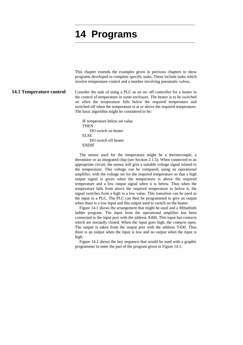
14 Programs
This chapter extends the examples given in previous chapters to showprograms developed to complete specific tasks. These include tasks whichinvolve temperature control and a number involving pneumatic valves.
14.1 Temperature control Consider the task of using a PLC as an on-off controller for a heater inthe control of temperature in some enclosure. The heater is to be switchedon when the temperature falls below the required temperature andswitched off when the temperature is at or above the required temperature.The basic algorithm might be considered to be:
IF temperature below set valueTHEN
DO switch on heaterELSE
DO switch off heaterENDIF
The sensor used for the temperature might be a thermocouple, athermistor or an integrated chip (see Section 2.1.5). When connected in anappropriate circuit, the sensor will give a suitable voltage signal related tothe temperature. This voltage can be compared, using an operationalamplifier, with the voltage set for the required temperature so that a highoutput signal is given when the temperature is above the requiredtemperature and a low output signal when it is below. Thus when thetemperature falls from above the required temperature to below it, thesignal switches from a high to a low value. This transition can be used asthe input to a PLC. The PLC can then be programmed to give an outputwhen there is a low input and this output used to switch on the heater.
Figure 14.1 shows the arrangement that might be used and a Mitsubishiladder program. The input from the operational amplifier has beenconnected to the input port with the address X400. This input has contactswhich are normally closed. When the input goes high, the contacts open.The output is taken from the output port with the address Y430. Thusthere is an output when the input is low and no output when the input ishigh.
Figure 14.2 shows the key sequence that would be used with a graphicprogrammer to enter the part of the program given in Figure 14.1.
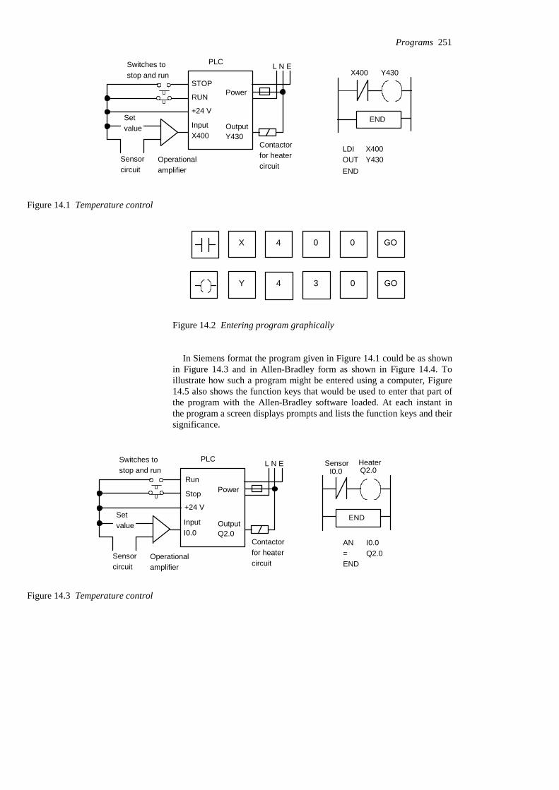
STOP
RUN
+24 V
InputX400
PLC
Operationalamplifier
Setvalue
Sensorcircuit
L N E
Power
OutputY430
Contactorfor heatercircuit
Switches tostop and run X400 Y430
LDIOUT
X400Y430
END
END
Figure 14.1 Temperature control
X 4 0 0 GO
Y 4 3 0 GO
Figure 14.2 Entering program graphically
In Siemens format the program given in Figure 14.1 could be as shownin Figure 14.3 and in Allen-Bradley form as shown in Figure 14.4. Toillustrate how such a program might be entered using a computer, Figure14.5 also shows the function keys that would be used to enter that part ofthe program with the Allen-Bradley software loaded. At each instant inthe program a screen displays prompts and lists the function keys and theirsignificance.
Q2.0
END
I0.0
AN=END
I0.0Q2.0
+24 V
InputI0.0
PLC
Operationalamplifier
Setvalue
Sensorcircuit
L N E
Power
OutputQ2.0
Contactorfor heatercircuit
Switches tostop and run
Stop
Run
Sensor Heater
Figure 14.3 Temperature control
Programs 251
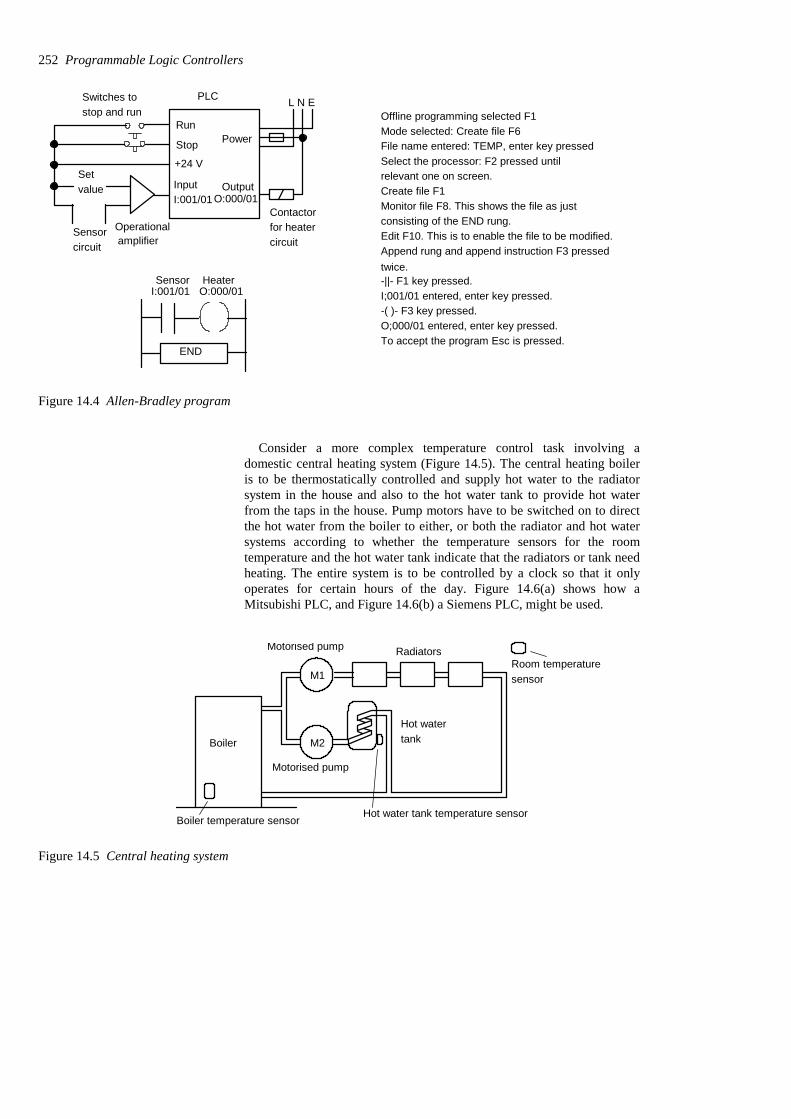
Offline programming selected F1Mode selected: Create file F6File name entered: TEMP, enter key pressedSelect the processor: F2 pressed until relevant one on screen.Create file F1Monitor file F8. This shows the file as just consisting of the END rung.Edit F10. This is to enable the file to be modified.Append rung and append instruction F3 pressedtwice.-||- F1 key pressed.I;001/01 entered, enter key pressed.-( )- F3 key pressed.O;000/01 entered, enter key pressed.To accept the program Esc is pressed.
+24 V
InputI:001/01
PLC
Operationalamplifier
Setvalue
Sensorcircuit
L N E
Power
OutputO:000/01
Contactorfor heatercircuit
Switches tostop and run
Stop
Run
I:001/01 O:000/01
END
Sensor Heater
Figure 14.4 Allen-Bradley program
Consider a more complex temperature control task involving adomestic central heating system (Figure 14.5). The central heating boileris to be thermostatically controlled and supply hot water to the radiatorsystem in the house and also to the hot water tank to provide hot waterfrom the taps in the house. Pump motors have to be switched on to directthe hot water from the boiler to either, or both the radiator and hot watersystems according to whether the temperature sensors for the roomtemperature and the hot water tank indicate that the radiators or tank needheating. The entire system is to be controlled by a clock so that it onlyoperates for certain hours of the day. Figure 14.6(a) shows how aMitsubishi PLC, and Figure 14.6(b) a Siemens PLC, might be used.
M1
M2
Motorised pump
Motorised pump
Hot watertankBoiler
Boiler temperature sensorHot water tank temperature sensor
RadiatorsRoom temperaturesensor
Figure 14.5 Central heating system
252 Programmable Logic Controllers

The boiler, output Y430/Q2.0, is switched on if X400/I0.0 and X401/I0.1 and either X402/I0.2 or X403/I0.3 are switched on. This means if theclock is switched on, the boiler temperature sensor gives an on input, andeither the room temperature sensor or the water temperature sensor giveon inputs. The motorised valve M1, output Y431/Q2.1, is switched on ifthe boiler, Y430/Q2.0, is on and if the room temperature sensor X402/I0.2gives an on input. The motorised valve M2, output Y432/Q2.2, isswitched on if the boiler, Y430/Q2.0, is on and if the water temperaturesensor gives an on input.
LDORAND
OUTLDANDOUTLDANDOUT
X402X403X400
Y430X402Y431Y430X403Y432
AND X401Y430
END
STOPRUN
+24 V
X400Inputs
X401
X402
X403
Stop and runswitches
Clock
Boiler
Water
Room
L N E
Power
OutputsY430
Y431
Y432
Boiler
M1
M2
X402 X400 X401 Y430
X403
Y430 X402 Y431
Y430 X403 Y432
Boiler
Radiator
Hot water
END
system
system
(a)
STOPRUN
+24 VInputs
Stop and runswitches
Clock
Boiler
Water
Room
L N E
Power
Outputs Boiler
M1
M2
I0.0
I0.1
I0.2
I0.3
Q2.0
Q2.1
Q2.2
(b)
I0.1 Q2.0
I0.3
Q2.0 I0.2 Q2.1
Q2.0 I0.3 Q2.2
Boiler
Radiator
Hot water
I0.2 I0.0
END
system
system
AO
A=AA=AA=
I0.2I0.3
I0.1Q2.0Q2.0I0.2Q2.1Q2.0I0.3Q2.2
A I0.0
END
Roomsensor Clock
Boilersensor
Watersensor
BoilerRoomsensor Valve M1
Boiler
Boiler Water sensor Valve M2
Roomsensor Clock
Boilersensor Boiler
Watersensor
BoilerRoomsensor Valve M1
Boiler Water sensor Valve M2
Figure 14.6 Central heating system: (a) Mitsubishi, (b) Siemens
Programs 253
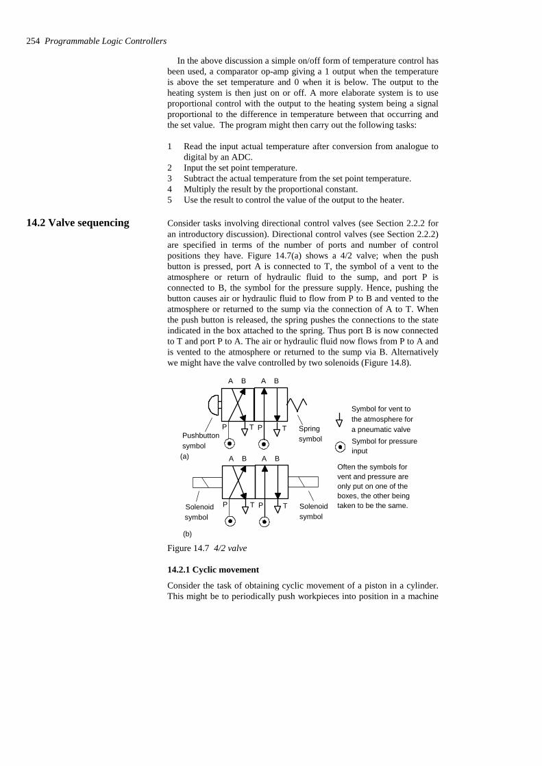
In the above discussion a simple on/off form of temperature control hasbeen used, a comparator op-amp giving a 1 output when the temperatureis above the set temperature and 0 when it is below. The output to theheating system is then just on or off. A more elaborate system is to useproportional control with the output to the heating system being a signalproportional to the difference in temperature between that occurring andthe set value. The program might then carry out the following tasks:
1 Read the input actual temperature after conversion from analogue todigital by an ADC.
2 Input the set point temperature.3 Subtract the actual temperature from the set point temperature.4 Multiply the result by the proportional constant.5 Use the result to control the value of the output to the heater.
14.2 Valve sequencing Consider tasks involving directional control valves (see Section 2.2.2 foran introductory discussion). Directional control valves (see Section 2.2.2)are specified in terms of the number of ports and number of controlpositions they have. Figure 14.7(a) shows a 4/2 valve; when the pushbutton is pressed, port A is connected to T, the symbol of a vent to theatmosphere or return of hydraulic fluid to the sump, and port P isconnected to B, the symbol for the pressure supply. Hence, pushing thebutton causes air or hydraulic fluid to flow from P to B and vented to theatmosphere or returned to the sump via the connection of A to T. Whenthe push button is released, the spring pushes the connections to the stateindicated in the box attached to the spring. Thus port B is now connectedto T and port P to A. The air or hydraulic fluid now flows from P to A andis vented to the atmosphere or returned to the sump via B. Alternativelywe might have the valve controlled by two solenoids (Figure 14.8).
A B A B
P T P T SpringsymbolPushbutton
symbol
A B A B
P T P T Solenoidsymbol
(a)
(b)
Solenoidsymbol
Symbol for vent tothe atmosphere fora pneumatic valveSymbol for pressureinput
Often the symbols forvent and pressure areonly put on one of theboxes, the other beingtaken to be the same.
Figure 14.7 4/2 valve
14.2.1 Cyclic movement
Consider the task of obtaining cyclic movement of a piston in a cylinder.This might be to periodically push workpieces into position in a machine
254 Programmable Logic Controllers
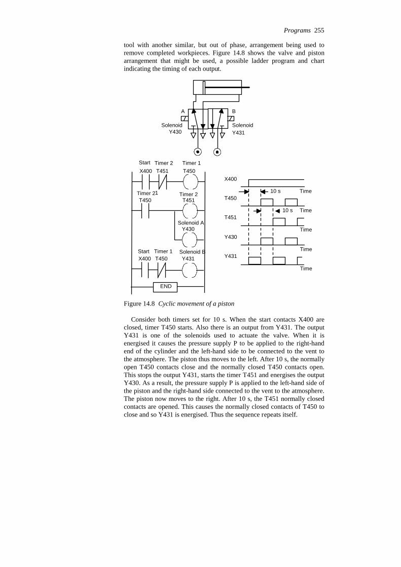
tool with another similar, but out of phase, arrangement being used toremove completed workpieces. Figure 14.8 shows the valve and pistonarrangement that might be used, a possible ladder program and chartindicating the timing of each output.
SolenoidY431
SolenoidY430
X400
Time
Time
Time
Time
Time
T450
T451
Y430
Y431
10 s
10 s
X400 T450T451
T450 T451
Y430
Y431T450X400
END
Start Timer 2 Timer 1
Timer 21 Timer 2
Solenoid A
Start Timer 1 Solenoid B
A B
Figure 14.8 Cyclic movement of a piston
Consider both timers set for 10 s. When the start contacts X400 areclosed, timer T450 starts. Also there is an output from Y431. The outputY431 is one of the solenoids used to actuate the valve. When it isenergised it causes the pressure supply P to be applied to the right-handend of the cylinder and the left-hand side to be connected to the vent tothe atmosphere. The piston thus moves to the left. After 10 s, the normallyopen T450 contacts close and the normally closed T450 contacts open.This stops the output Y431, starts the timer T451 and energises the outputY430. As a result, the pressure supply P is applied to the left-hand side ofthe piston and the right-hand side connected to the vent to the atmosphere.The piston now moves to the right. After 10 s, the T451 normally closedcontacts are opened. This causes the normally closed contacts of T450 toclose and so Y431 is energised. Thus the sequence repeats itself.
Programs 255

14.2.2 Sequencing
Consider another task involving three pistons A, B and C that have to beactuated in the sequence: A to the right, A to the left, B to the right, B tothe left, C to the right, C to the left (such a sequence is often written A+,A−, B+, B−, C+, C−). Figure 14.9 illustrates the valves that might be usedand Figures 14.10 and Figure 14.11 ladder programs that might be usedinvolving timers. An alternative would involve the use of a shift register.
A
Y430
Y431
Q2.0
Q2.1
B
Y432
Y433
Q2.2
Q2.3
C
Y434
Y435
Q2.4
Q2.5
Figure 14.9 The valves
X400/I0.0 is the start switch. When it is closed there is an output fromY430/Q2.0 and the timer T450/T0 starts. The start switch is latched by theoutput. Piston A moves to the right. After the set time, K = 4, the normallyclosed timer T450/internal relay F0.0 contacts open and the normallyopen timer T450/internal relay F0.0 contacts close. This switches offY430/Q2.0 and energises Y431/Q2.1 and starts timer T451/T1. Piston Amoves to the left. In rung 2, the T450/internal relay F0.0 contacts arelatched and so the output remains on until the set time has been reached.When this occurs the normally closed timer T451/internal relay F0.1contacts open and the normally open T451/ internal relay F0.1 contactsclose. This switches off Y431/Q2.1 and energises Y432/Q2.2 and startstimer T452/T2. Piston B moves to the right. Each succeeding rungactivates the next solenoid. Thus in sequence, each of the outputs isenergised.
256 Programmable Logic Controllers

X400 T450 Y431 Y432 Y433 Y434 Y435 Y430
T450
K4
Y430
T450
T451
T451
T452
T452
T453
T453
T454
T454
K4
K4
K4
K4
T455
K4
T455
T454
T453
T452
T451 Y431
Y432
Y433
Y434
Y435
Y435
Y434
Y433
Y432
Y431
Piston A moves to right
Piston A moves to left
Piston B moves to right
Piston B moves to left
Piston C moves to right
Piston C moves to left
END
Start Timer 0Solenoids
A– B+ B– C+ C– Solenoid A++ represents piston extension– represents piston retraction
A+ Timer 0
Timer 0 Timer 1 Solenoid A–
Timer 1A–
Timer 1 Timer 2 Solenoid B+
B+ Timer 2
Solenoid B–Timer 3Timer 2
B– Timer 3
Timer 3 Timer 4 Solenoid C+
C+ Timer 4
Timer 4 Timer 5 Solenoid C–
C– Timer 5
Figure 14.10 Mitsubishi format program
Programs 257

I0.0 F0.0 Q2.1 Q2.2 Q2.3 Q2.4 Q2.5
Timer 0Q2.0
Timer 1
F0.1
Q2.1
Piston A moves to right
Piston A moves to left
Piston B moves to right
Piston B moves to left
Piston C moves to right
Piston C moves to left
4
END
4
Q2.0
Q
F0.0
F0.0 Q2.1
F0.1
Timer 2
F0.2
Q2.2
4
F0.1 Q2.2
F0.2
Timer 3
F0.3
Q2.3
4
F0.2 Q2.3
F0.3
Timer 4
F0.4
Q2.4
4
F0.3 Q2.4
F0.4
Timer 5
F0.5
Q2.5
4
F0.4 Q2.5
F0.5
Q
Q
Q
Q
Q
TV
TV
TV
TV
TV
TV
S TON
STON
STON
STON
STON
STON
Start Timer 0 A– B+ B– C+ C– Solenoid A+ + represents piston extension– represents piston retraction
Solenoids
A+
Timer 0 Timer 1 A–
A–
Timer 1 Timer 2 B+
B+
Timer 2 Timer 3 B–
B–
C+Timer 3 Timer 4
C+
Timer 4 Timer 5 C–
C–
Figure 14.11 Siemens format program
258 Programmable Logic Controllers
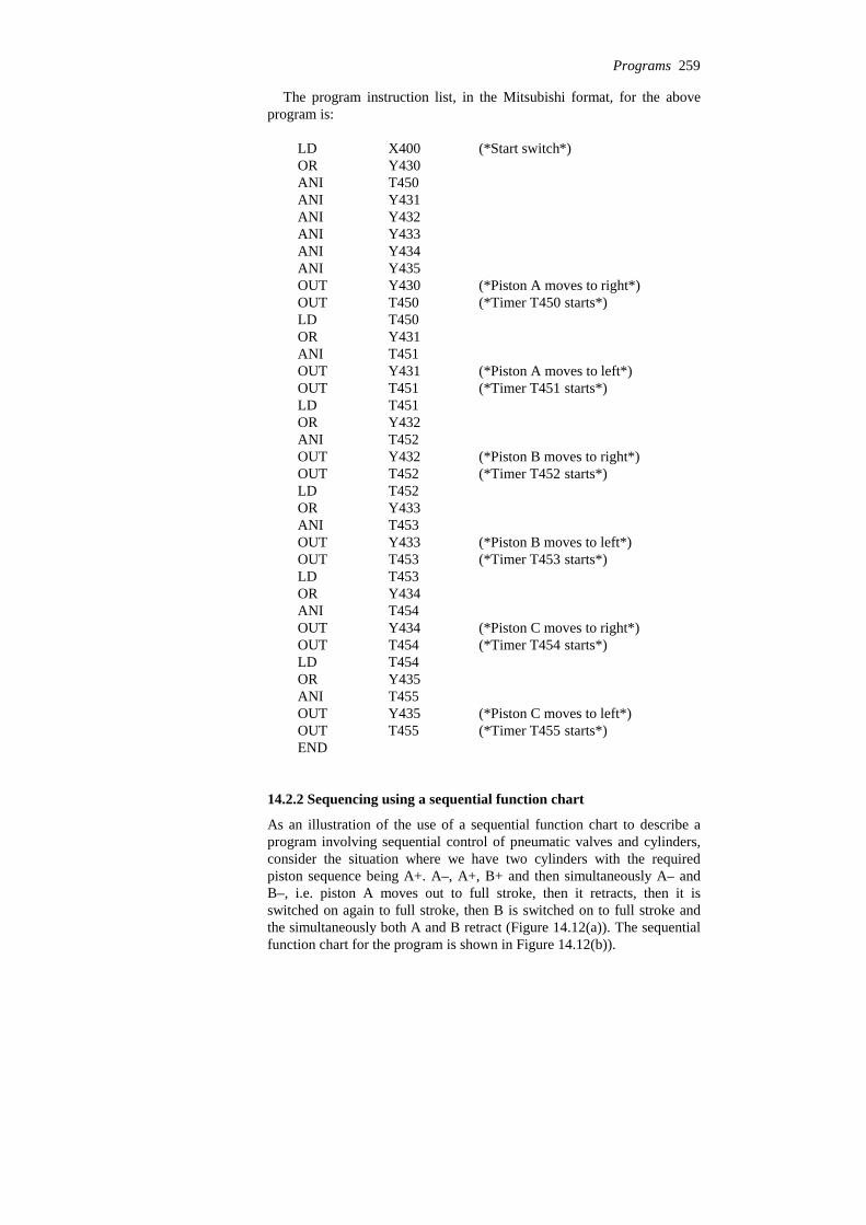
The program instruction list, in the Mitsubishi format, for the aboveprogram is:
END(*Timer T455 starts*)T455OUT(*Piston C moves to left*)Y435OUT
T455ANIY435ORT454LD
(*Timer T454 starts*)T454OUT(*Piston C moves to right*)Y434OUT
T454ANIY434ORT453LD
(*Timer T453 starts*)T453OUT(*Piston B moves to left*)Y433OUT
T453ANIY433ORT452LD
(*Timer T452 starts*)T452OUT(*Piston B moves to right*)Y432OUT
T452ANIY432ORT451LD
(*Timer T451 starts*)T451OUT(*Piston A moves to left*)Y431OUT
T451ANIY431ORT450LD
(*Timer T450 starts*)T450OUT(*Piston A moves to right*)Y430OUT
Y435ANIY434ANIY433ANIY432ANIY431ANIT450ANIY430OR
(*Start switch*)X400LD
14.2.2 Sequencing using a sequential function chart
As an illustration of the use of a sequential function chart to describe aprogram involving sequential control of pneumatic valves and cylinders,consider the situation where we have two cylinders with the requiredpiston sequence being A+. A–, A+, B+ and then simultaneously A– andB–, i.e. piston A moves out to full stroke, then it retracts, then it isswitched on again to full stroke, then B is switched on to full stroke andthe simultaneously both A and B retract (Figure 14.12(a)). The sequentialfunction chart for the program is shown in Figure 14.12(b)).
Programs 259
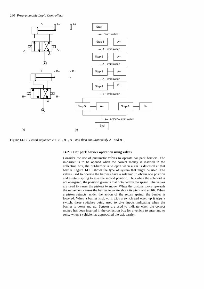
B B– B+
B–B+
A A– A+
A–A+
Start
Start switch
A+
A–
A+
B+
A–
Step 1
Step 2
Step 3
Step 4
Step 5
A+ limit switch
A– limit switch
A+ limit switch
B+ limit switch
A– AND B– limit switch
B–Step 6
End(a) (b)
Figure 14.12 Piston sequence B+. B–, B+, A+ and then simultaneously A– and B–.
14.2.3 Car park barrier operation using valves
Consider the use of pneumatic valves to operate car park barriers. Thein-barrier is to be opened when the correct money is inserted in thecollection box, the out-barrier is to open when a car is detected at thatbarrier. Figure 14.13 shows the type of system that might be used. Thevalves used to operate the barriers have a solenoid to obtain one positionand a return spring to give the second position. Thus when the solenoid isnot energised, the position given is that obtained by the spring. The valvesare used to cause the pistons to move. When the pistons move upwardsthe movement causes the barrier to rotate about its pivot and so lift. Whena piston retracts, under the action of the return spring, the barrier islowered. When a barrier is down it trips a switch and when up it trips aswitch, these switches being used to give inputs indicating when thebarrier is down and up. Sensors are used to indicate when the correctmoney has been inserted in the collection box for a vehicle to enter and tosense when a vehicle has approached the exit barrier.
260 Programmable Logic Controllers
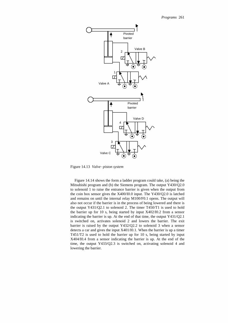
2
1
Pivotedbarrier
Valve A
Valve B
3
4
Pivotedbarrier
Valve C
Valve D
Figure 14.13 Valve-piston system
Figure 14.14 shows the form a ladder program could take, (a) being theMitsubishi program and (b) the Siemens program. The output Y430/Q2.0to solenoid 1 to raise the entrance barrier is given when the output fromthe coin box sensor gives the X400/I0.0 input. The Y430/Q2.0 is latchedand remains on until the internal relay M100/F0.1 opens. The output willalso not occur if the barrier is in the process of being lowered and there isthe output Y431/Q2.1 to solenoid 2. The timer T450/T1 is used to holdthe barrier up for 10 s, being started by input X402/I0.2 from a sensorindicating the barrier is up. At the end of that time, the output Y431/Q2.1is switched on, activates solenoid 2 and lowers the barrier. The exitbarrier is raised by the output Y432/Q2.2 to solenoid 3 when a sensordetects a car and gives the input X401/I0.1. When the barrier is up a timerT451/T2 is used to hold the barrier up for 10 s, being started by inputX404/I0.4 from a sensor indicating the barrier is up. At the end of thetime, the output Y433/Q2.3 is switched on, activating solenoid 4 andlowering the barrier.
Programs 261

X400 M100 Y431 Y430
Y430
M100 X402 Y430 Y431
Y431
X403 M101 Y433 Y432
Y432
M101 X405 Y432 Y433
Y433
X400 is coin operated switchY430 is output to solenoid 1
Y431 is output to solenoid 2X402 is input indicating barrier down
To lift entrance barrier
Timer T459 gives the up time, 10 sfor the entry barrier
M100 is internal relay
To lift exit barrierY432 is output to solenoid 3
Y433 is the output to solenoid 4
To lower entrance barrier
To close exit barrier
X401 is input indicating barrier up
Up time for exit barrier, 10 sM101 is internal relayX404 indicates exit barrier is up
X401
M100
X404
M101
X403 is the input when car atthe exit barrier
X405 indicates exit barrier is down
T450
K10
T450
T451
T451
END
LDORANI
OUTLDOUTKLDOUTLDORANIANIOUTLDORANIANIOUTLDOUTKLDOUTLDORANIANIOUTEND
X400Y430M100Y431Y430X401T45010T450M100M100Y431X402Y430Y431X403
ANI
Y432M101Y433Y432X404T45110T451M101M101Y433X405Y432Y433
Coin switch Valve A, 1Valve B, 2
A, 1
In barrier up Timer 0
Timer 0
In barrier down A, 1 Valve B, 2
B, 2
Car at exit D, 4 Valve C, 3
C, 3
Exit barrier up Timer 1
Timer 1
Exit barrier down C, 3 D, 4
D, 4
Figure 14.14 (a) Car barrier program, Mitsubishi format
262 Programmable Logic Controllers

I0.0 F0.1 Q2.1 Q2.0
Q2.0
F0.1 I0.2 Q2.0 Q2.1
Q2.1
I0.3 F0.2 Q2.3 Q2.2
Q2.2
F0.2 I0.5 Q2.2 Q2.3
Q2.3
I0.0 is coin operated switchQ2.0 is output to solenoid 1
Q2.1 is output to solenoid 2I0.2 is input indicating barrier down
To lift entrance barrier
Timer T1 gives the up time, 10 sfor the entry barrierF0.1 is internal relay
To lift exit barrierQ2.2 is output to solenoid 3
Q2.3 is the output to solenoid 4
To lower entrance barrier
To close exit barrier
I0.1 is input indicating barrier up
Up time for exit barrier, 10 sF0.2 is internal relayI0.4 indicates exit barrier is up
I0.1 Timer 1
KT10.2
Q
F0.1
I0.4 Timer 2
KT10.2
Q
F0.2
I0.3 is the input when car atthe exit barrier
I0.5 indicates exit barrier is down
END
AOANAN=ALKTSRA=AOANAN=AOANAN=ALKTSRA=AOANAN=END
I0.0Q2.0F0.1Q2.1Q2.0I0.1I0.2T0T0Q2.0F0.1Q2.1I0.2Q2.0Q2.1I0.3Q2.2F0.2Q2.3Q2.2I0.4I0.2T1T1F0.2F0.2Q2.3I0.5Q2.2Q2.3
STON
TV
S
TV
TON
Coin switch Timer 1 B, 2 Valve A, 1
A, 1
In barrier up
Timer 1 Valve B, 2A, 1In barrier down
B, 2
Car at exit Timer 2 D, 4 Valve B, 2
B, 2
Exit barrier up
Timer 2 Valve D, 4Exit barrier down
D, 4
Figure 14.14 (b) Car barrier program, Siemens format
Programs 263
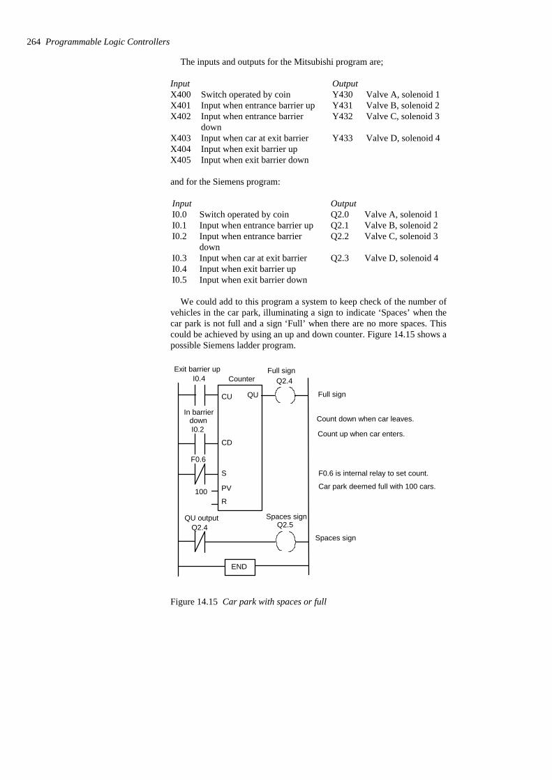
The inputs and outputs for the Mitsubishi program are;
Input when exit barrier downX405Input when exit barrier upX404
Valve D, solenoid 4Y433Input when car at exit barrierX403
Valve C, solenoid 3Y432Input when entrance barrierdown
X402Valve B, solenoid 2Y431Input when entrance barrier upX401Valve A, solenoid 1Y430Switch operated by coinX400
OutputInput
and for the Siemens program:
Input when exit barrier downI0.5Input when exit barrier upI0.4
Valve D, solenoid 4Q2.3Input when car at exit barrierI0.3
Valve C, solenoid 3Q2.2Input when entrance barrierdown
I0.2Valve B, solenoid 2Q2.1Input when entrance barrier upI0.1Valve A, solenoid 1Q2.0Switch operated by coinI0.0
OutputInput
We could add to this program a system to keep check of the number ofvehicles in the car park, illuminating a sign to indicate ‘Spaces’ when thecar park is not full and a sign ‘Full’ when there are no more spaces. Thiscould be achieved by using an up and down counter. Figure 14.15 shows apossible Siemens ladder program.
CU
CD
S
PV
R100
Spaces sign
Full sign
I0.4
I0.2
Q2.4
Q2.5Q2.4
F0.6
Count down when car leaves.
Count up when car enters.
F0.6 is internal relay to set count.
Car park deemed full with 100 cars.
END
QU
Exit barrier upCounter
In barrierdown
QU output Spaces sign
Full sign
Figure 14.15 Car park with spaces or full
264 Programmable Logic Controllers
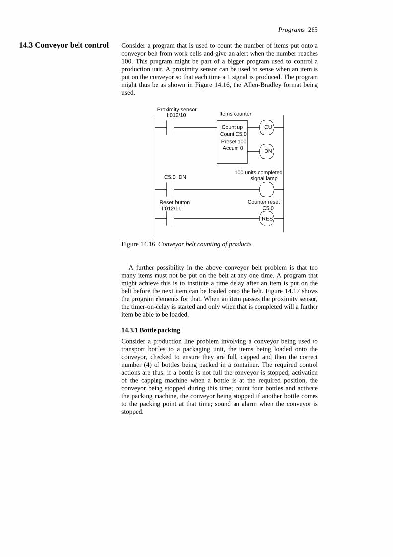
14.3 Conveyor belt control Consider a program that is used to count the number of items put onto aconveyor belt from work cells and give an alert when the number reaches100. This program might be part of a bigger program used to control aproduction unit. A proximity sensor can be used to sense when an item isput on the conveyor so that each time a 1 signal is produced. The programmight thus be as shown in Figure 14.16, the Allen-Bradley format beingused.
CU
DN
Items counter
Count upCount C5.0Preset 100Accum 0
Proximity sensorI:012/10
C5.0 DN100 units completed
signal lamp
Reset buttonI:012/11
Counter resetC5.0
RES
Figure 14.16 Conveyor belt counting of products
A further possibility in the above conveyor belt problem is that toomany items must not be put on the belt at any one time. A program thatmight achieve this is to institute a time delay after an item is put on thebelt before the next item can be loaded onto the belt. Figure 14.17 showsthe program elements for that. When an item passes the proximity sensor,the timer-on-delay is started and only when that is completed will a furtheritem be able to be loaded.
14.3.1 Bottle packing
Consider a production line problem involving a conveyor being used totransport bottles to a packaging unit, the items being loaded onto theconveyor, checked to ensure they are full, capped and then the correctnumber (4) of bottles being packed in a container. The required controlactions are thus: if a bottle is not full the conveyor is stopped; activationof the capping machine when a bottle is at the required position, theconveyor being stopped during this time; count four bottles and activatethe packing machine, the conveyor being stopped if another bottle comesto the packing point at that time; sound an alarm when the conveyor isstopped.
Programs 265

DN
Proximity sensorI:012/11
Reset buttonI:012/11
RES
Conveyor Time delay
ENTimer on DelayTimer T4.1Time Base 1:0Preset 180Accum 0
TON
Conveyor time delayT4:1 DN
T4:1
O:013:02Output to switch off loading
O:013/02Switch off loading
O:012/01Loading mechanism
I:012/10
Sensor for itemready for loading
O:012/01
Figure 14.17 Conveyor belt time delays
The detection of whether a bottle is full could be done with aphotoelectric sensor which could then be used to activate a switch(X402/I0.2 input). The presence of a bottle for the capping machine couldalso be by means of a photoelectric sensor (X403/I0.3 input). The input tothe counter to detect the four bottles could be also from a photoelectricsensor (X404/I0.4 input). The other inputs could be start (X400/I0.0input) and stop (X401/I0.1 input) switches for the conveyor and a signal(X405/I0.5 input) from the packaging machine as to when it is operating,having got four bottles and so is not ready for any further caps. Figure14.18 shows a possible ladder program in Mitsubishi format, and Figure14.19 in Siemens format, that could be used.
The Mitsubishi program in instruction list is:
Y431OUT(*Second rung*)Y430LDI
Y430OUTANB
X405ORIX404LDIM100ANIY432ANIX401ANY430OR
(*First rung*)X400LD
266 Programmable Logic Controllers

X400
Y430
X401
X405
Y430 Y430 is the output to theconveyor. X400 is the start button,
Y431 Y431 is the output to thealarm. It is triggered when
Y430
X402
M100
Y432
T450 is a timer whichstops the conveyor for time taken to cap thebottle. Y432 energises
X403
Y432
T450T450
Y432the capping machine and
M100
M100 X404
X405
RST
C460
C460 K4X404 X405
Reset for the counterwhen packaging machine has 4 bottles.
Y433C460
END
M100 is an internal relayactivated by X402 closing
X401 the stop button - externally setclosed. The conveyor isstopped by Y232, M100,X404 or X405 being activated.
the conveyor stops.
when a bottle is not full. Itthen stops the conveyor.
stops the conveyor.
X404 input when bottledetected. X405 opens whenpacking occurring. 4 bottles counted.
Y433 energises packingmachine when C460 hascounted 4 bottles.
Start Stop Conveyor
Bottle not full
Bottle not full
Conveyorstop
Conveyor
Conveyor Alarm
Bottle present Timer Timer
Capping Capping
4 bottles Counter
Counter
Counter
Bottle present Packing occurring
Packing machine
Capping
Figure 14.18 Bottle packing program
Programs 267

I0.0
Q2.0
I0.1
I0.5
Q2.0
Q2.0 is the output to theconveyor. I0.0 is the start button,
Q2.1
Q2.1 is the output to thealarm. It is triggered when
Q2.0
I0.2
F0.0
Q2.2
T1 is a timer whichstops the conveyor for time taken to cap thebottle.
I0.3
Q2.2
Q2.2 the capping machine and
F0.0
F0.0 I0.4
I0.4 I0.5 Q2.3
END
F0.0 is an internal relayactivated by I0.2 closing
I0.1 the stop button - externallyset. The conveyor isstopped by Q2.2, F0.0,I0.4 or I0.5 being activated.
the conveyor stops.
when a bottle is not full. Itthen stops the conveyor.
stops the conveyor.
I0.4 input when bottledetected. I0.5 opens whenpacking occurring. 4 bottles counted.
Q2.3 energises packingmachine when counter hascounted 4 bottles.
F0.1
F0.1
Timer T0
2.2
CU
I0.5R
PV4
Q2.2 energises
Q
Couter C0
TONQS
TV
S_CU
Start Stop Capping Bottle not full Conveyor
ConveyorstopConveyor
Conveyor Alarm
Bottle not full
Bottle present
Capping
Capping
Packing machineBottle presentPackingoccurring
4 bottles
Figure 14.19 Bottle packing program
C460RST(*Fifth rung*)X405LD
Y432OUT(*2 s allowed for capping.*)2K
T450OUTT450ANIY432OR
(*Fourth rung*)X403LDM100OUTM100OR
(*Third rung*)X402LD
268 Programmable Logic Controllers
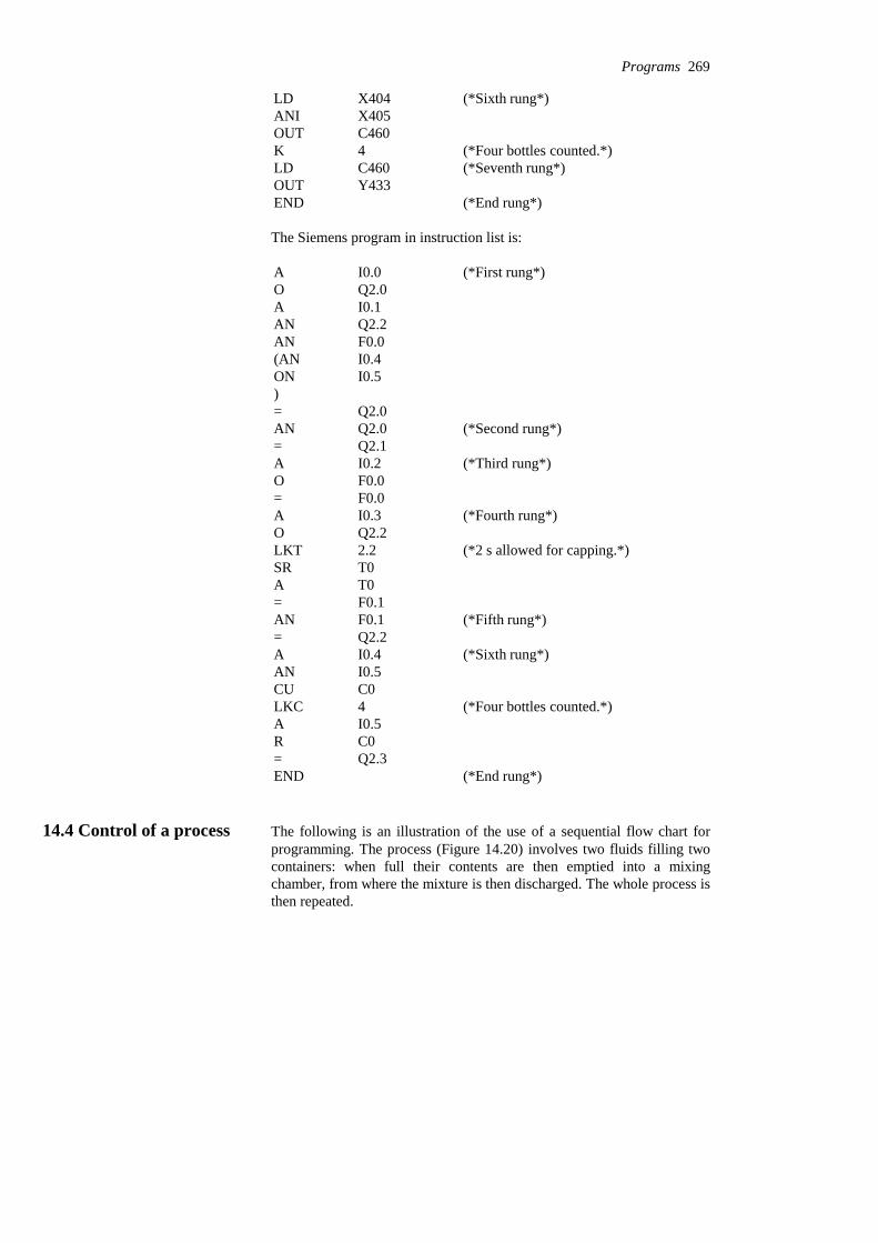
(*End rung*)ENDY433OUT
(*Seventh rung*)C460LD(*Four bottles counted.*)4K
C460OUTX405ANI
(*Sixth rung*)X404LD
The Siemens program in instruction list is:
(*End rung*)ENDQ2.3=C0RI0.5A
(*Four bottles counted.*)4LKCC0CUI0.5AN
(*Sixth rung*)I0.4AQ2.2=
(*Fifth rung*)F0.1ANF0.1=T0AT0SR
(*2 s allowed for capping.*)2.2LKTQ2.2O
(*Fourth rung*)I0.3AF0.0=F0.0O
(*Third rung*)I0.2AQ2.1=
(*Second rung*)Q2.0ANQ2.0=
)I0.5ONI0.4(ANF0.0ANQ2.2ANI0.1AQ2.0O
(*First rung*)I0.0A
14.4 Control of a process The following is an illustration of the use of a sequential flow chart forprogramming. The process (Figure 14.20) involves two fluids filling twocontainers: when full their contents are then emptied into a mixingchamber, from where the mixture is then discharged. The whole process isthen repeated.
Programs 269
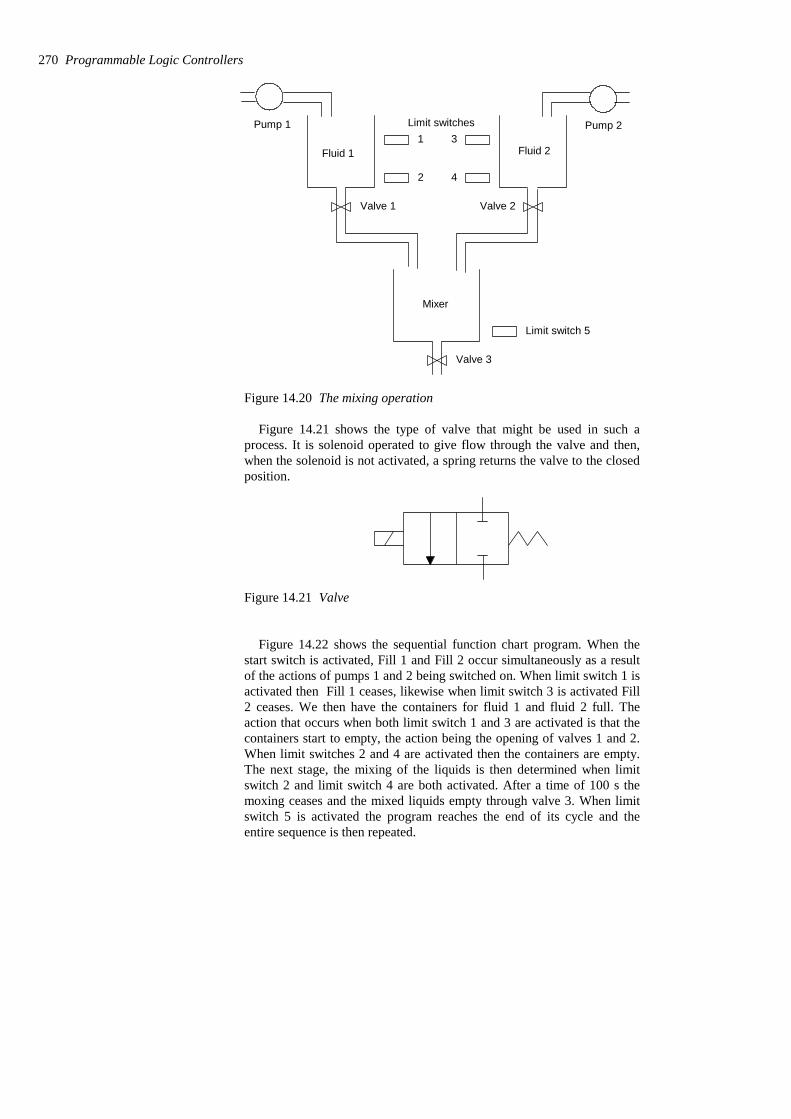
Fluid 1 Fluid 2
Valve 1 Valve 2
Mixer
Valve 3
1
2
3
4
Limit switchesPump 1 Pump 2
Limit switch 5
Figure 14.20 The mixing operation
Figure 14.21 shows the type of valve that might be used in such aprocess. It is solenoid operated to give flow through the valve and then,when the solenoid is not activated, a spring returns the valve to the closedposition.
Figure 14.21 Valve
Figure 14.22 shows the sequential function chart program. When thestart switch is activated, Fill 1 and Fill 2 occur simultaneously as a resultof the actions of pumps 1 and 2 being switched on. When limit switch 1 isactivated then Fill 1 ceases, likewise when limit switch 3 is activated Fill2 ceases. We then have the containers for fluid 1 and fluid 2 full. Theaction that occurs when both limit switch 1 and 3 are activated is that thecontainers start to empty, the action being the opening of valves 1 and 2.When limit switches 2 and 4 are activated then the containers are empty.The next stage, the mixing of the liquids is then determined when limitswitch 2 and limit switch 4 are both activated. After a time of 100 s themoxing ceases and the mixed liquids empty through valve 3. When limitswitch 5 is activated the program reaches the end of its cycle and theentire sequence is then repeated.
270 Programmable Logic Controllers
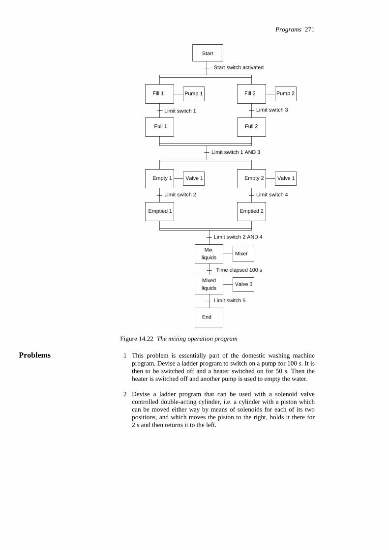
Start
Start switch activated
Fill 1 Fill 2Pump 1 Pump 2
Limit switch 1 Limit switch 3
Full 1 Full 2
Limit switch 1 AND 3
Empty 1 Valve 1 Empty 2 Valve 1
Limit switch 2 Limit switch 4
Emptied 1 Emptied 2
Limit switch 2 AND 4
MixerMix
liquids
Time elapsed 100 s
Valve 3Mixedliquids
Limit switch 5
End
Figure 14.22 The mixing operation program
Problems 1 This problem is essentially part of the domestic washing machineprogram. Devise a ladder program to switch on a pump for 100 s. It isthen to be switched off and a heater switched on for 50 s. Then theheater is switched off and another pump is used to empty the water.
2 Devise a ladder program that can be used with a solenoid valvecontrolled double-acting cylinder, i.e. a cylinder with a piston whichcan be moved either way by means of solenoids for each of its twopositions, and which moves the piston to the right, holds it there for2 s and then returns it to the left.
Programs 271
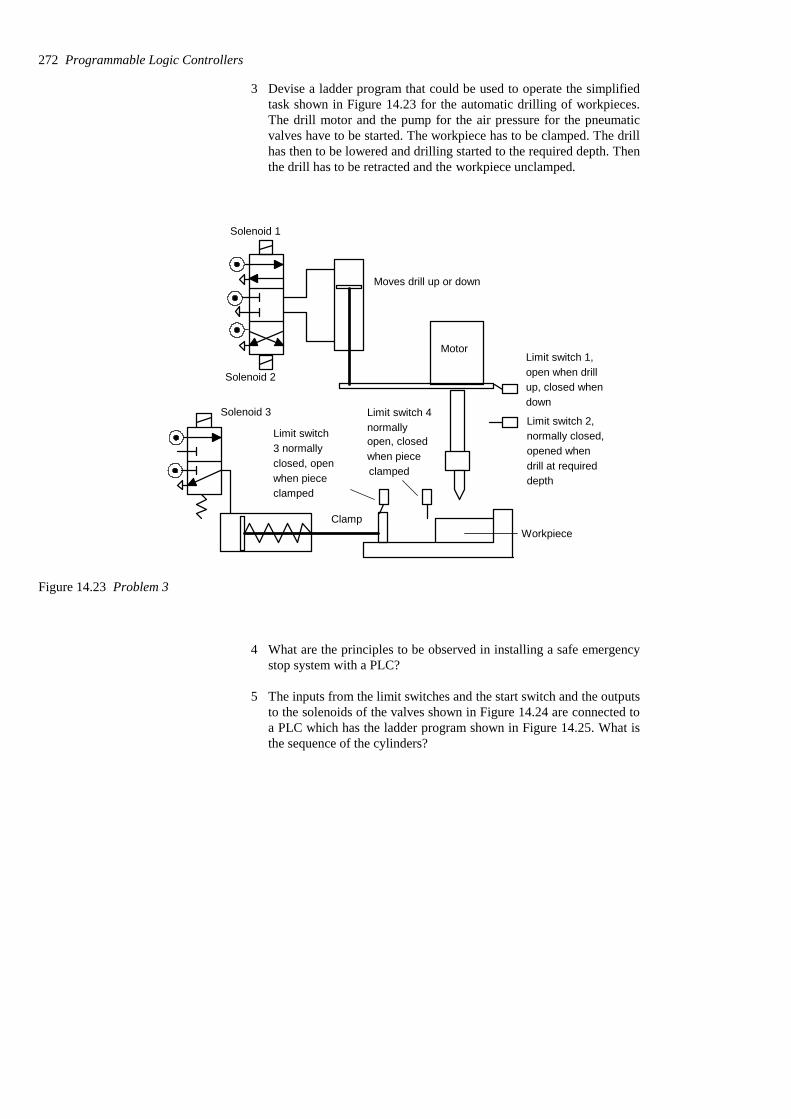
3 Devise a ladder program that could be used to operate the simplifiedtask shown in Figure 14.23 for the automatic drilling of workpieces.The drill motor and the pump for the air pressure for the pneumaticvalves have to be started. The workpiece has to be clamped. The drillhas then to be lowered and drilling started to the required depth. Thenthe drill has to be retracted and the workpiece unclamped.
Solenoid 1
Solenoid 2
Motor
Moves drill up or down
ClampWorkpiece
Solenoid 3
Limit switch 1,open when drill
Limit switch 2,normally closed,Limit switch
3 normallyclosed, open
Limit switch 4normallyopen, closed
opened whendrill at requireddepth
up, closed whendown
when piececlampedwhen piece
clamped
Figure 14.23 Problem 3
4 What are the principles to be observed in installing a safe emergencystop system with a PLC?
5 The inputs from the limit switches and the start switch and the outputsto the solenoids of the valves shown in Figure 14.24 are connected toa PLC which has the ladder program shown in Figure 14.25. What isthe sequence of the cylinders?
272 Programmable Logic Controllers

B
b– b+
B+ B–
A
a– a+
A+ A–
–V
C
c+
C+ C–
c–
Figure 14.24 Problem 5Start
Start
A+
B+
a+ b+ C+
c+ A–
c+ B–
a– b– C–
END
Figure 14.25 Problem 5
Programs 273

6 The inputs from the limit switches and the start switch and the outputsto the solenoids of the valves shown in Figure 14.26(a) are connectedto a PLC which has the ladder program shown in Figure 14.26(b).What is the sequence of the cylinders?
END
IR 1 IR 2 Start A+
IR 1 IR 2
IR 1 IR 2 a+ B+
IR 1 IR 2
IR 1 IR 2
A–
IR 1 IR 2 a– B–
IR 1 IR 2 b+ IR 1 IR 1
IR 1 IR 2
a+
IR 1 IR 2 b– IR 1 IR 2
IR 2 IR 2
a–
A
a– a+
A+ A–
B
b– b+
B+ B–
(a)
(b)
Figure 14.26 Problem 6
274 Programmable Logic Controllers
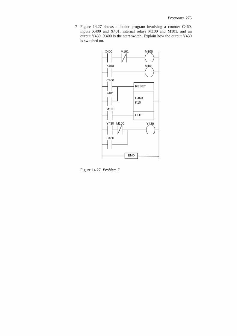
7 Figure 14.27 shows a ladder program involving a counter C460,inputs X400 and X401, internal relays M100 and M101, and anoutput Y430. X400 is the start switch. Explain how the output Y430is switched on.
RESET
C460K10
OUT
X400 M101 M100
X400 M101
C460
X401
M100
Y430 M100
C460
Y430
END
Figure 14.27 Problem 7
Programs 275
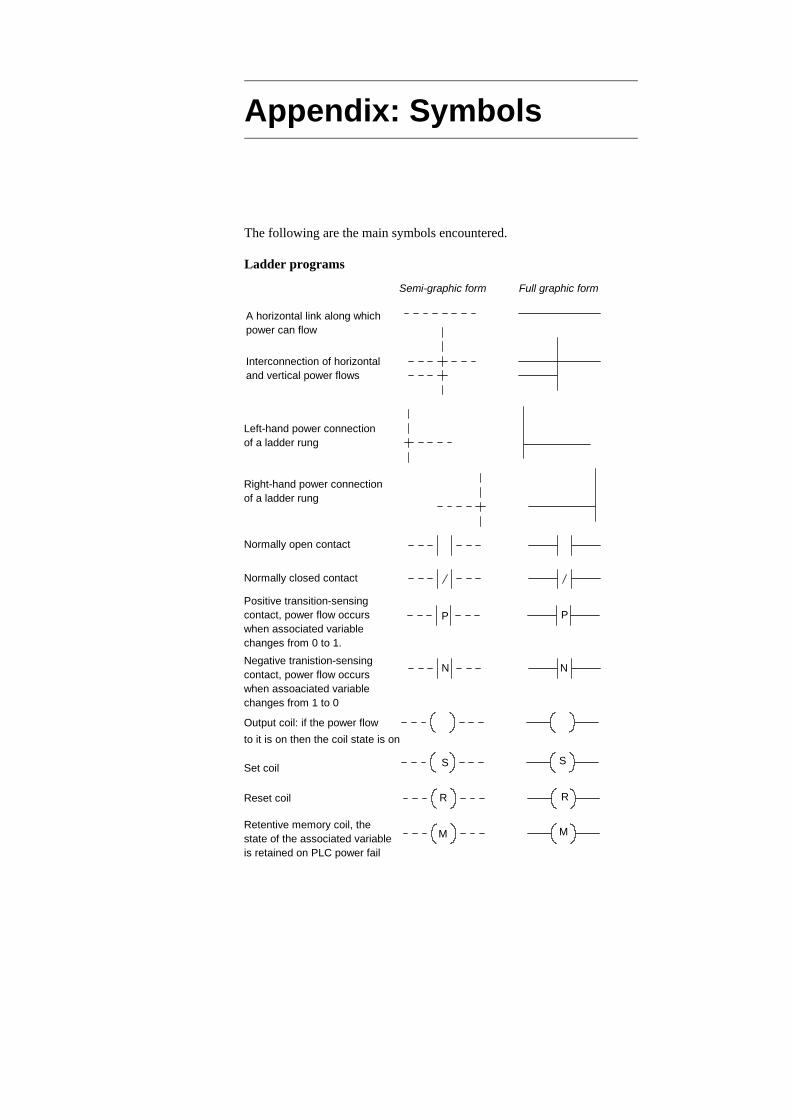
Appendix: Symbols
The following are the main symbols encountered.
Ladder programs
Semi-graphic form Full graphic form
A horizontal link along whichpower can flow
Interconnection of horizontaland vertical power flows
Left-hand power connectionof a ladder rung
Right-hand power connectionof a ladder rung
Normally open contact
Normally closed contact
Output coil: if the power flowto it is on then the coil state is on
Set coil S S
Reset coil R R
M MRetentive memory coil, thestate of the associated variableis retained on PLC power fail
P P
N N
Positive transition-sensingcontact, power flow occurswhen associated variablechanges from 0 to 1.Negative tranistion-sensingcontact, power flow occurswhen assoaciated variablechanges from 1 to 0

Function blocksSemi-graphic form Full graphic form
Interconnection of horizontaland vertical signal flows
Crossing horizontal andvertical signal flows
Horizontal and vertical lines
Blocks with connections
Connectors AV_WEIGHT
AV_WEIGHT
AV_WEIGHT
AV_WEIGHT
Commonly encountered blocks:
CTUCU Q
R
PV CV
BOOL
INT
BOOL
BOOL
INT
Up-counter counts the number
BOOL is Boolean signal, INT is integer, REAL is a floating point number,
CTDCD Q
LD
PV CV
BOOL
INT
BOOL
BOOL
INT
of rising edges at input CU.PV defines the maximumvalue of the counter. Eachnew rising edge at CU increments CV by 1. OutputQ occurs after set count. R
Down-counter counts down the number of rising edges at input CU. PV defines the startingvalue of the counter. Eachnew rising edge at CU decrements CV by 1. OutputQ occurs when count reaches.
is the reset.
zero.
ANY is any form of signal
CTUD
CDQU
LDPV CV
BOOL
INT
BOOL
BOOLINT
Up-down counter. It can be BOOL CU
RBOOLBOOLQDused to count up on one
input and down on the other.
Appendix: Symbols 277

On-delay timer. When input INgoes true, the elapsed time atabout ET starts to increase andwhen it reaches the set time,specified by input PT, the outputQ goes true.
TONBOOL
TIME
BOOL
TIME
IN
PT
Q
ET
TOFBOOL
TIME
BOOL
TIME
IN
PT
Q
ET
Off-delay timer. When input INgoes true, the output Q followsand remains true for the settime after the input Q goesfalse.
TPBOOL
TIME
BOOL
TIME
IN
PT
Q
ET
Pulse timer. When input IN goestrue, output Q follows and remainstrue for the pulse durationspecified by input PT.
Logic gates
A
B
OutputInputs
OutputA
B
Inputs &AND gate
OR gate
A
B
OutputInputs
A
B
OutputInputs 1m
Not gateInput
OutputA
Input
OutputA1
A
B
OutputInputs
A
B
OutputInputs &NAND gate
A
B
OutputInputs
A
B
OutputInputs >1NOR Gate
XOR GateOutput
A
B
InputsOutput
=1A
B
Inputs
278 Programmable Logic Controllers
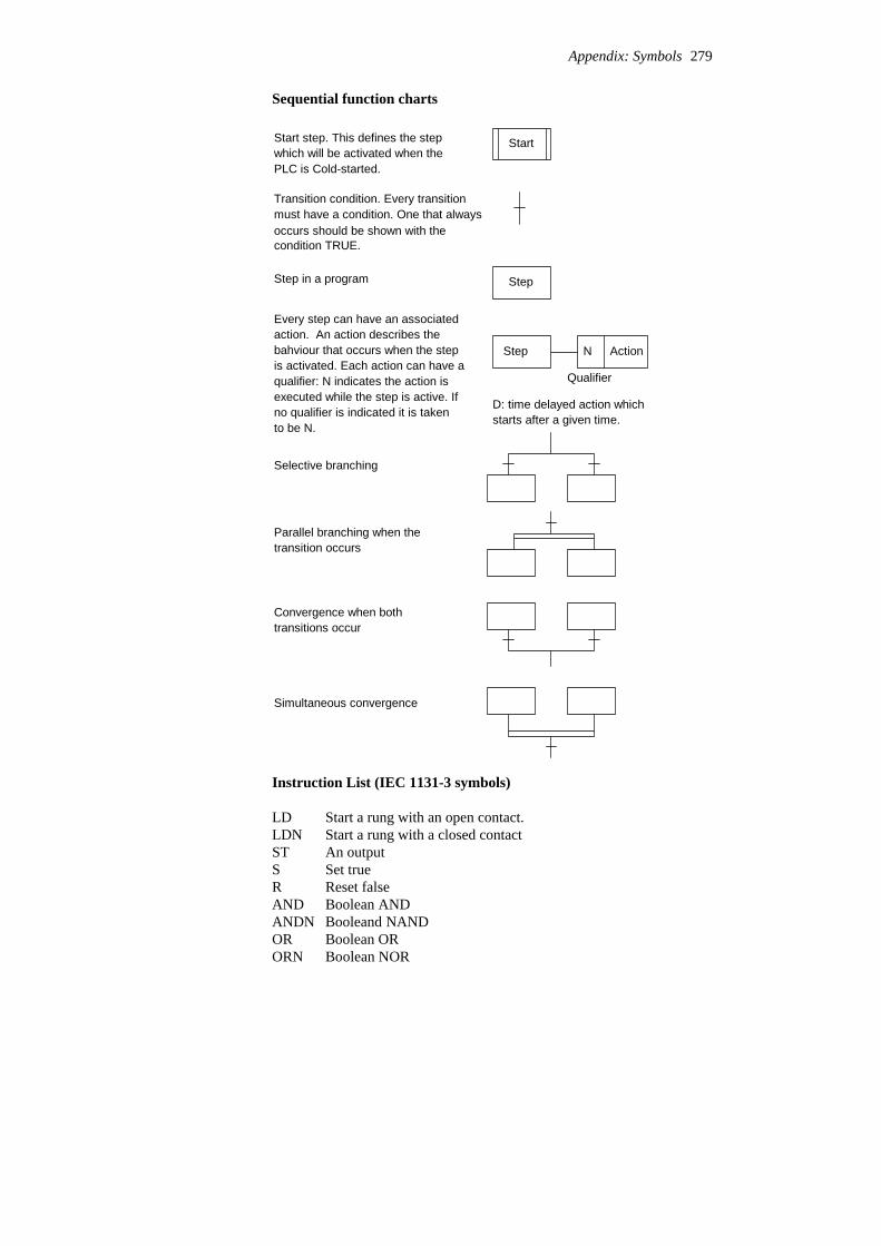
Sequential function charts
StartStart step. This defines the step
Transition condition. Every transition
StepStep in a program
which will be activated when thePLC is Cold-started.
must have a condition. One that alwaysoccurs should be shown with thecondition TRUE.
Every step can have an associatedaction. An action describes the
ActionNbahviour that occurs when the stepis activated. Each action can have aqualifier: N indicates the action isexecuted while the step is active. If
Step
Qualifier
no qualifier is indicated it is takento be N.
D: time delayed action whichstarts after a given time.
Selective branching
Parallel branching when the
Convergence when bothtransitions occur
transition occurs
Simultaneous convergence
Instruction List (IEC 1131-3 symbols)
LD Start a rung with an open contact.LDN Start a rung with a closed contactST An outputS Set trueR Reset falseAND Boolean ANDANDN Booleand NANDOR Boolean ORORN Boolean NOR
Appendix: Symbols 279
XOR Boolean XORNOT Boolean NOTADD AdditionSUB SubtractionMUL MultiplicationDIV Division
Structured text
X := Y Y represents an expression that produces a new value for the variable X.
Operators
Boolean ORORBoolean XORXORBoolean ANDAND, &Equality, inequality=, <>
Less than, greater than, less than or equal to, greaterthan or equal to
<, >, <=, >=Addition, subtraction+, -Multiplication, division, modulus operation*, /, MODNegation, Boolean NOT-, NOTRaising to a power**List of parameters of a functionFunction(...)Parenthised (bracketed) expression(...)
Conditional and iteration statementsIF ... THEN ... ELSE is used when selected statements are to be executedwhen certain conditions occur.The FOR ... DO iteration statement allows a set of statements to berepeated depending on the value of the iteration integer variable.The WHILE ... DO iteration statement allows one or more statements tobe executed while a particular Boolean expression remains true.The REPEAT ... UNTIL iteration statement allows one or morestatements to be executed and repeated whilst a particular Booleanexpression remains true.
280 Programmable Logic Controllers
Answers
6 C 5 A 4 A 3 C 2 A 1 DChapter 1 7 See Figure 1.4. 8 See Figure 1.7 and associated text. 9 See Section 1.3.4.10 2 × 1024.
10 C 9 B 8 A 7 A
6 A 5 C 4 D 3 B 2 A 1 AChapter 2
11 See (a) Figure 2.5, (b) Section 2.1.4, (c) Section 2.1.3, (d) Section2.1.8.
12 See Section 2.2.3.13 See Section 2.2.4.
Chapter 3 1 (a) 3, (b) 63, (c) 13 2 (a) 110 0100, (b) 1001 0010, (c) 1111 1111 3 (a) 159, (b) 3411, (c) 1660 4 (a) E, (b) 51, (c) A02 5 (a) 1110, (b) 11101, (c) 1010 0110 0101 6 (a) 250, (b) 12, (c) 1376 7 (a) 24, (b) 411, (c) 620 8 (a) 010 111 000, (b) 001 000 010, (c) 110 111 011 9 (a) 0010 0000, (b) 0011 0101, (c) 1001 001010 (a) 1111 1111, (b) 1101 1101, (c) 1000 001111 (a) –16, (b) –55, (c) –4012 (a) 0.110010 % 2–3, (b) 0.1100 % 2–4, (c) 0.1000 0100 % 24
9 D 8 D 7 A
6 C 5 A 4 C 3 C 2 A 1 BChapter 4
10 (a) 0, (b) 1.11 To detect message corruption.12 See Section 4.5.
18 C17 C16 A15 B14 C13 D12 B11 A10 A 9 C 8 D 7 B
6 B 5 B 4 B 3 B 2 D 1 AChapter 5
21 A20 C19 D22 See (a) Figure 5.8, (b) Figure 5.10, (c) Figure 5.19, (d) Figure 5.10,
(e) Figure 5.11, (f) Figure 5.5(a).
21 B20 C19 A18 C17 D16 A15 C14 A13 B12 A11 B10 A 9 D 8 B 7 A
6 C 5 A 4 D 3 B 2 A 1 CChapter 6
21 B20 A19 A18 B17 A16 A15 A14 C13 B12 B11 B10 D 9 C 8 A 7 A
6 C 5 C 4 A 3 C 2 B 1 DChapter 7
22 See (a) Figure 7.8, (b) Figures 7.10 or 7.11, (c) Figure 7.26.
4 B 3 A 2 B 1 CChapter 8
19 C18 D17 A16 B15 D14 B13 A12 A11 A10 C 9 B 8 C 7 C
6 D 5 D 4 D 3 D 2 A 1 CChapter 9
20 See (a) Figure 9.4, (b) Figure 9.10, (c) Figure 9.12.
19 A18 C17 C16 D15 B14 C13 B12 B11 A10 A 9 C 8 D 7 B
6 B 5 B 4 B 3 C 2 A 1 CChapter 10
20 See (a) Figures 10.3, (b) Figures 10.7.
9 D 8 C 7 C
6 A 5 A 4 D 3 C 2 C 1 DChapter 11
10 (a) As Figure 11.1/11.2 with a constant input to In 1/X400, soentering a 1 at each shift, (b) As in Figure 11.3 but instead of faultyitem, hook with an item, and instead of good item, hooks with noitems.
9 C 8 B 7 B
6 A 5 A 4 B 3 B 2 C 1 CChapter 12
282 Programmable Logic Controllers

10 Similar to (a) Figure 12.5, (b) Figure 12.6.
6 A 5 A 4 C 3 B 2 C 1 BChapter 13 7 See Section 13.3.1. 8 Power failure, supply off, power tripped. 9 Wiring fault, device fault.10 See Figure A.1.11 See Figure A.2.
Start for Out 1 Out 1 Start switch closes and startsOut 1, which in the absence of a fault takes acertain time to complete
Out 1 Timer 1
Timer 1
Timer 2
Timer 3
Plus timersfor other outputs
Plus similar rungs for theother outputs
Timer 1 is set for slightly
END
Stop for Out 1
longer than completiontime for Out 1
If any output takes longerthan expected, theinternal relay is energised.
IR
IR
When this happens it switches off all the outputrungs in which it islocated
Figure A.1 Chapter 13, problem 10
A
a– a+
A+ A–
B
b– b+
B+ B–
(a) The pneumatics
Figure A.2 (Continued on next page)
Answers 283
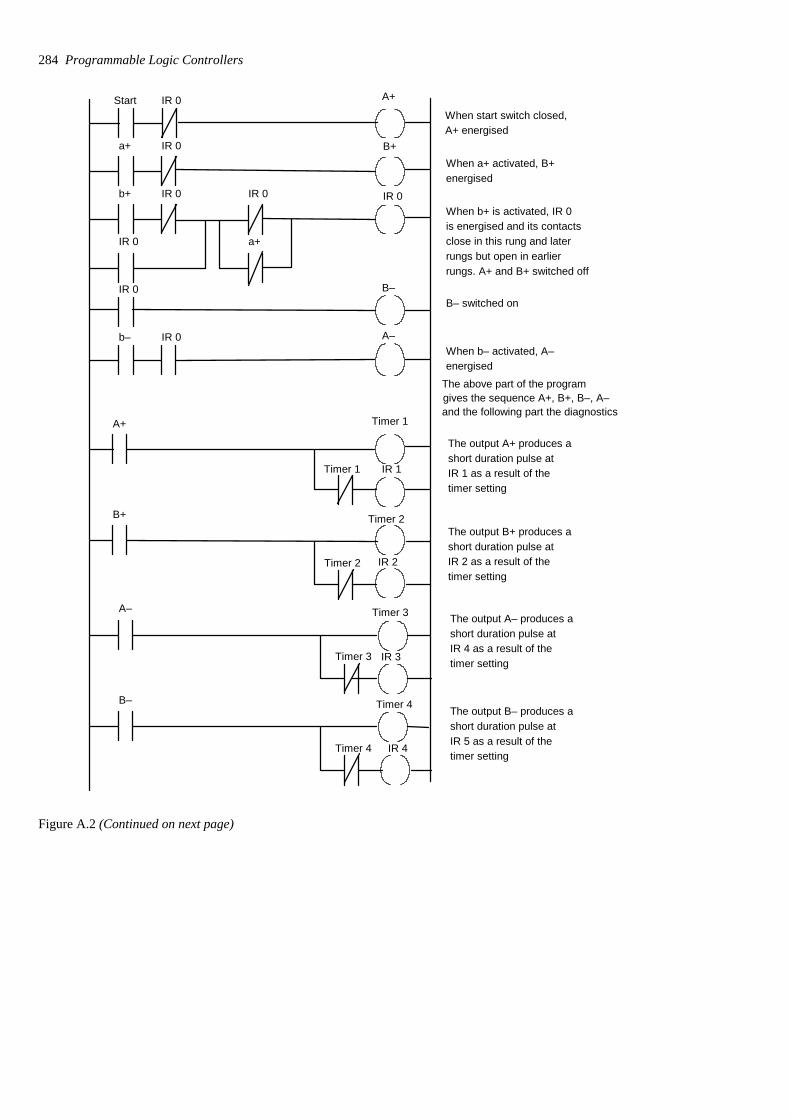
Start IR 0 A+
a+ IR 0 B+
b+ IR 0 IR 0
IR 0 a+
IR 0
IR 0 B–
b– IR 0 A–
When start switch closed,A+ energised
When a+ activated, B+energised
When b+ is activated, IR 0is energised and its contactsclose in this rung and later rungs but open in earlierrungs. A+ and B+ switched off
B– switched on
When b– activated, A–energised
gives the sequence A+, B+, B–, A–
A+ Timer 1
Timer 1 IR 1
B+ Timer 2
Timer 2 IR 2
The output A+ produces ashort duration pulse atIR 1 as a result of thetimer setting
The output B+ produces ashort duration pulse atIR 2 as a result of thetimer setting
The above part of the program
and the following part the diagnostics
A– Timer 3
Timer 3 IR 3
B– Timer 4
Timer 4 IR 4
The output A– produces ashort duration pulse atIR 4 as a result of thetimer setting
The output B– produces ashort duration pulse atIR 5 as a result of thetimer setting
Figure A.2 (Continued on next page)
284 Programmable Logic Controllers

IR 1 LED A+
LED A+
IR 2 IR 3 IR 4 Reset If A+ output occurs, IR 1 closesand is latched on. LED A+ isthen on. LED A+ is not onunless IR 1 closed
IR 2 IR 1 IR 3 IR 4 Reset LED B+
LED B+
If B+ output occurs, IR 2 closesand is latched on. LED B+ isthen on. LED B+ is not onunless IR 2 closed
END
IR 3 IR 1 IR 2 IR 4 Reset LED A–
LED A–
IR 4 IR 1 IR 2 IR 3 Reset LED B–
LED B–
If A– output occurs, IR 3 closesand is latched on. LED A– isthen on. LED A– is not onunless IR 2 closed
If B– output occurs, IR 4 closesand is latched on. LED B– isthen on. LED B– is not onunless IR 4 closed
Figure A.2 Chapter 13, problem 11
Chapter 14 1 See Figure A.3. 2 See Figure A.4. 3 See Figure A.5 for a basic answer. 4 Hard-wired emergency stop button, not dependent on software. 5 A+ and B+, C+, A– and B–, C–. 6 A+, B+, A–, B–, A+, A–. 7 M100 and M101 activated. Ten pulses on X401 counted. Then
output.
Answers 285

Start Y431 Y432 Y430
Y430 T450K100
T450 T451 Y431 Y432
Y432
Y432 T451K50
T451 T452 Y430 Y431
Y431
Y431 T452 K100
Y430 is the supply
Y432 is the heater
Y431 is the
T450 is supply pump
T451 is the heater
T452 is the
pump
timer
timer
discharge pump
discharge pump timer
Y430
Figure A.3 Chapter 14, problem 1
Start Stop Y430
Y430 is air pressure supply
Y431Sensor 1Sensor 1 is a limit switch for piston at left. Y431 is solenoidto move piston to right
Sensor 2 T450 Sensor 2 is a limit switch for piston at right. T450 has K2
Y432T450Y432 is solenoid to move piston to left
Y430
Figure A.4 Chapter 14, problem 2
286 Programmable Logic Controllers
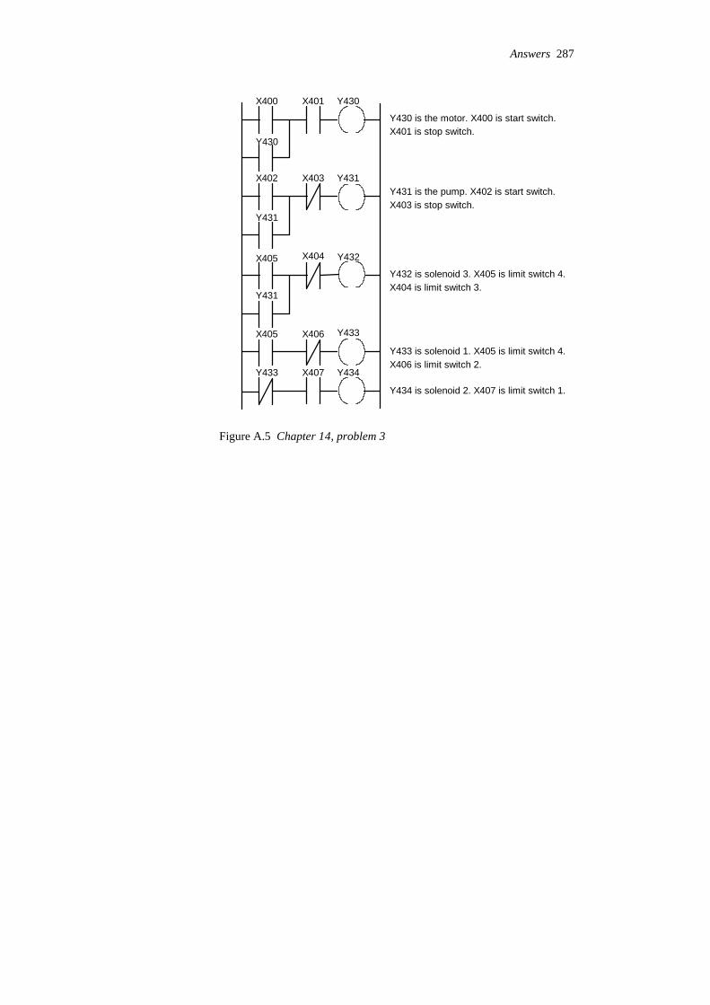
Y430
Y430 is the motor. X400 is start switch.
Y431Y431 is the pump. X402 is start switch.
Y432
Y432 is solenoid 3. X405 is limit switch 4.
Y433 is solenoid 1. X405 is limit switch 4.
Y434 is solenoid 2. X407 is limit switch 1.
Y434
Y433
X401X400
Y430
X402 X403
Y431
X405 X404
Y431
X405 X406
Y433 X407
X401 is stop switch.
X403 is stop switch.
X404 is limit switch 3.
X406 is limit switch 2.
Figure A.5 Chapter 14, problem 3
Answers 287

Absolute encoder, 22Accuracy, 17Actuator, 30ADC, 55Addresses, 76, 82Alarm system, 141, 201Algorithm, 210Allen-Bradley
addresses, 77arithmetic operations, 202bit storage, 133counter, 174, 178data comparison, 200data highway, 75jump, 154latch/unlatch, 136, 139master control relay, 143move, 198PLC-5, 12program, 84, 140, 227, 240,
265RsLogix, 15, 93sequencer, 182subroutine, 156timer, 160, 164timer extension, 179
Amplifier, operational, 60Analogue
signals, 5, 53standard, 59-to-digital converter, 55
AND, 84Arithmetic and logic unit, 6ASCII code, 69Assembly code, 81
Baud rate, 65BCD, see Binary coded decimal
systemBimetal strip, 24Binary
arithmetic, 47
coded decimal system, 47, 197
number system, 44one’s complement, 49signed, 48two’s complement, 49, 197
Bits, 6, 44, 189Bit storage, 132BOOL, 51Boolean algebra, 97Box form of PLC, 10Brick, 10Bus, 5, 7Byte, 8
Car park barrier, 260Carrier sense multiple access, 71Central processing unit, 5Coaxial cabling, 63Commissioning, 218Contactor, 30Continuous updating, 75Control system
closed loop, 203tasks, 1unit, 6
Conveyor belt, 39, 265Counters
down-counter, 173forms of, 173IEC 1131-3, 173, 178programming, 174up and down, 178up-counter, 173
CPU, see Central processing unitCSMA, 71Cutting band saw program, 227Cycle, 75, 82Cyclic redundancy check, 69Cylinder
control, 33double acting, 33
Index

Cylinder, continuedsingle acting, 32
DAC, 57Darlington pair, 21Data Highway Plus, 71Denary number system, 44Derivative control, 205Digital
signals, 5, 53-to-analogue converter, 57
DINT, 51Discrete signals, 5, 53Displacement sensor, 26Documentation, system, 227Domestic washing machine, 117
EEPROM, 30Emergency stop
relays, 217switches, 102, 216
Encoder, 22EPROM, 7Error, 17Ethernet, 74Expected value checks, 226
Fail-safe, 215Fault finding, 220Feedback loop, 97Fibre-optic cabling, 63Fixed point numbers, 50Flags, 65, 132Flashing light, 166Flip-flop, 138, 141Floating point numbers, 50Flow charts, 210Flow meter, 29Function block
AND, 96equivalent ladder, 96feedback loop, 97NAND, 96negated input/output, 95NOR, 96OR, 96XOR, 96programming, 94symbols, 277
GEM-80 addresses, 77
GENET, 71Gray code, 23
Hexadecimal number system, 46Hysteresis error, 17
IEC 1131-3, 51, 80, 83, 94, 108, 113, 136, 137, 138, 159, 173,192, 205
IEC 61508, 215IEEE 1451.4, 30IEEE 488, 66IEEE/ANSI logic symbols, 95Increment encoder, 22Input
devices, 17/output addresses, 76/output processing, 53/output unit, 8processing, 75unit, 53
Instruction listAND, 109and ladder programs, 109IEC 1131-3, 108, 113labels, 109mnemonics, 108, 279NAND, 111NOR, 110OR, 110XOR, 112
INT, 51Integral control, 205ISO/OSI model, 72
Jump, 154
Ladder programmingAND, 85, 133and flow charts, 210and instruction lists, 109counters, 173data comparison, 200entering, 93equivalent functional block,
97equivalent sequential function
chart, 117, 119internal relays, 132latching, 90, 134monitoring, 221
Index 289

Ladder programming, continuedmultiple outputs, 91NAND, 88NOR, 89NOT, 87OR, 86principle, 80sequenced outputs, 92shift register, 190symbols, 83, 276timers, 160XOR, 90
LAN, 69Last output set, 222LED, 21Lift, 39Light-emitting diode, 21Limit switch, 20Linear variable differential
transformer, 26LINT, 51Liquid level detector, 29, 40LM35, 25LM3911N, 25Logic functions, 84, 95, 278Loop, 20 mA, 65LREAL, 51LVDT, see Linear variable
differential transformer
Machine code, 80, 93Manufacturing automation
protocol, 73MAP, 73Markers, 132Mass I/O copying, 75MelsecNET, 71MELSOFT, 14, 93Memory, 7Mitsubishi
addresses, 77auxiliary relay, 133cascaded timers, 161counter, 173, 174, 176data comparison, 200jump, 154marker, 133master control relay, 143, 144MELSEC FX3U, 10, 76monitoring, 220move, 198, 199
program, 84, 91, 92, 109, 110, 111, 112, 113, 114,
115, 134, 138, 194, 250,252, 255, 256, 260, 266
pulse operation, 138shift register, 190, 191subroutine, 156timers, 160
Modular form of PLC, 10Motor d.c.
basic form, 34brushless, 35control, 35
Motor, stepper, 36Motorola MPX100AP, 28
NAND, 87Negative transition-sensing coil,
138Network, local area, 69Non-linearity error, 17NOR, 88NOT, 87
Octal number system, 45OMRON
CPM1A, 11CX-One, 15
One-shot, 137Open systems interconnection
model, 72Operational amplifier, 60Optoisolators, 8OR, 85Orifice flow meter, 29Output
devices, 30relay, 9, 57transistor, 9, 57triac, 10, 57
Parallel communicationprinciples, 63standards, 66
Parity check, 68Photoconductive cell, 21Photodiode, 21Photoelectric sensors, 21PID control, 205PLC, see Programmable logic
controller
290 Programmable Logic Controllers

Position sensor, 26Positive transition sensing coil,
138Potential divider, 60Potentiometer, 26Pressure sensors, 28Process control, 269Programmable logic controller
advantages, 3architecture, 5continuous updating, 75cycle, 75function, 3I/O processing, 53, 75input units, 53internal relays, 132linking, 62mass I/O copying, 75output units, 56programming, 14, 80safety, 218timers, 159types, 10
Proportional control, 204Protocols, 64, 68Proximity switches, 20Pseudocode, 210Pulse width modulation, 34
Rack form of PLC, 10RAM, 7Range, 18REAL, 51Reed switch, 21Registers, 6, 189, 197Relay
battery-backed, 136internal, 132 master control, 142output device, 30retentive, 136
Reliability, 19Remote connections, 62Replication, 224Resistive temperature detector, 24Response time, 18Retentive memory coil, 136Rise time, 18Robot, 39ROM, 7RS232, 64
RS422, 65RS423, 65RSLogix, 93RTD, 24
SAA 1027, 38Safe systems, 214SCADA, 72Scientific notation, 51Sensitivity, 18Sensor, 17Sequencer, 180Sequential function chart
actions, 119and flow charts, 210convergence, 117equivalent ladder, 117, 119parallel branching, 117principles, 116process control, 269sequencing, 250selective branching, 117states, 116steps, 116symbols, 279transitions, 116
Serial communicationprinciples, 63RS232, 64standards, 63
Set/reset, 138Settling time, 18Shift register
IEC 1131-3 symbol, 192principles, 189
Siemensaddresses, 77arithmetic operations, 203BCD/binary, 202counter, 173, 174, 178data comparison, 200flags, 133jump, 155move, 199program, 84, 92, 96, 109,
110, 111, 112, 113, 114, 134, 141, 240, 252, 256,260, 266
set/reset, 140, 141shift register, 192STEP 7, 14, 93
Index 291

Siemens, continuedsubroutine, 156timers, 160, 163, 164
Signal conditioning, 59lamp program, 100, 114
Simulation, 220SINECL, 71Sinking, 10, 53, 56Smart sensors, 30Sourcing, 10, 53, 56Stability, 19STEP 7, 93Stepper motor
action, 36bipolar, 38hybrid, 37permanent magnet, 36unipolar, 38variable reluctance, 37
Stop switches, 102, 215Strain gauges, 27, 61Structured text
assignment, 120conditional statements, 122data comparison, 200iteration statements, 122language, 120move, 198operators, 121symbols, 280traffic lights, 167
Subroutine, 156Switch sensors, 19
TEDs, 30Telemecanique, 15, 108, 133, 139,
141, 160Temperature
control, 250sensors, 24
Testing, 218Texas Instrument TSL220, 22Thermocouple, 25
Thermodiode, 24Thermotransistor, 24Time representation, 51Timers
cascaded, 161IEC 1131-3, 159off-delay, 159, 163on-delay, 159on-off cycle, 162pulse, 159, 165programming, 160sequencing with, 161types, 159
TIWAY, 71Toshiba, 133, 141, 160, 162, 174,
181, 191Traffic lamp sequence, 115, 167Transducer, 17Truth table, 85Twister-pair cabling, 63
UDINT, 51UINT, 51ULINT, 51USINT, 51
Valve actuation, 32control positions, 32directional control, 31operation program, 100, 115ports, 32sequencing, 145, 176, 193,
254, 256solenoid operated, 31spool, 31symbol, 32
Watchdog timer, 221Wheatstone bridge, 24, 27, 61Word, 7, 51, 197
XOR, 89
292 Programmable Logic Controllers