PROGRAMMABLE LOGIC CONTROLLER. Control Systems Types Programmable Logic Controllers Distributed...
37
PROGRAMMABLE LOGIC CONTROLLER
-
Upload
earl-brooks -
Category
Documents
-
view
239 -
download
2
Transcript of PROGRAMMABLE LOGIC CONTROLLER. Control Systems Types Programmable Logic Controllers Distributed...

PROGRAMMABLE LOGIC
CONTROLLER

Control Systems TypesControl Systems Types
Programmable Logic Controllers Distributed Control System PC- Based Controls
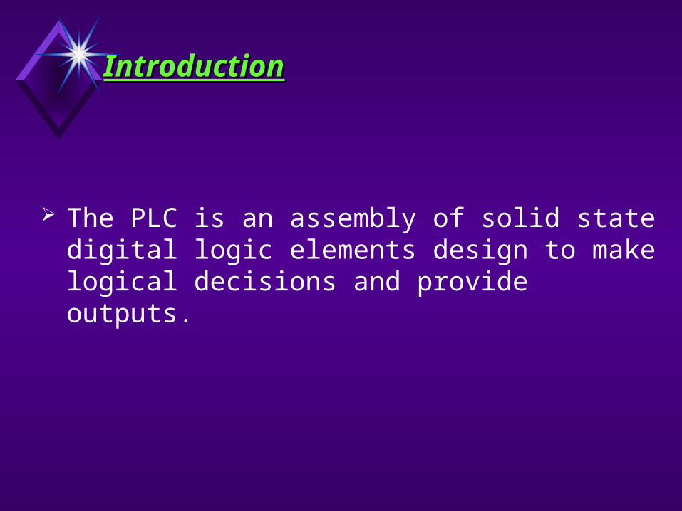
IntroductionIntroduction
The PLC is an assembly of solid state digital logic elements design to make logical decisions and provide outputs.

Programmable Logic Programmable Logic Controllers Controllers
Sequential logic solver PID Calculations. Advanced Subroutines BIT Operations. Data Transfer. Text Handling.

Applications : Machine controls, Packaging, Palletizing, Material handling,
similar Sequential task as well as Process control
Advantages of PLC : They are fast and designed for the rugged industrial
environment. They are attractive on Cost-Per-Point Basis. These Devices are less Proprietary ( E.g.. Using Open Bus
Interface.) These Systems are upgraded to add more Intelligence and
Capabilities with dedicated PID and Ethernet Modules.
Disadvantages of PLC : PLC were Designed for Relay Logic Ladder and have Difficulty
with some Smart Devices. To maximize PLC performance and Flexibility, a number of
Optional Modules must be added
Programmable Logic Programmable Logic Controllers Controllers

PLC Types Nano (Small) Micro (Medium) Large
Basic criteria for PLC Types Memory Capacity I/O Range Packaging and Cost per Point
Programmable Logic Programmable Logic Controllers Controllers

Central Processing Unit (CPU) Input Output Modules Power Supply Bus system Programming Device
P L C Components P L C Components
CPU
PROGRAMDEVICE
IN OUT m
MODULEMODULE

It is a micro-controller based circuitary. The CPU consists of following blocks :
Arithmatic Logic Unit (ALU), Program memory Process image memory (Internal memory of CPU) Internal timers and counters Flags CPU performs the task necessary to fulfill the PLC funtions. These
tasks include Scanning, I/O bus traffic control, Program execution, Peripheral and External device communication, special functions or data handling execution and self diagnistics.
P L C : Central Processing P L C : Central Processing Unit Unit

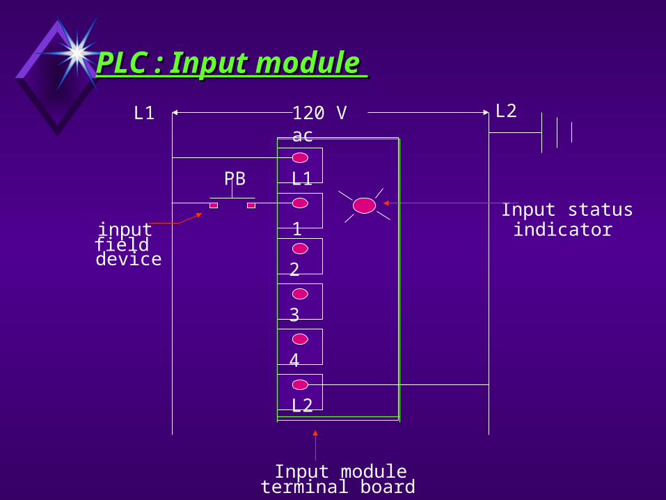
These modules act as interface between real-time status of process variable and the CPU.
Analog input module : Typical input to these modules is 4-20 mA, 0-10 V Ex : Pressure, Flow, Level Tx, RTD (Ohm), Thermocouple (mV) Digital input module : Typical input to these modules is 24 V
DC, 115 V AC, 230 V AC Ex. : Switches, Pushbuttons, Relays, pump valve on off status
PLC : Input module PLC : Input module
120 V acL1 L2
L2
L1
1
2
3
4
PB
inputfield
device
Input moduleterminal board
Input statusindicator
PLC : Input module PLC : Input module

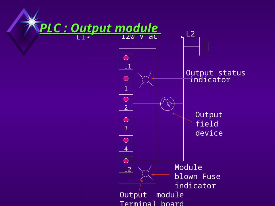
These modules act as link between the CPU and the output devices in the field.
Analog output module : Typical output from these modules is 4-20 mA, 0-10 V
Ex : Control Valve, Speed, Vibration Digital output module : Typical output from these modules is
24 V DC, 115 V AC, 230 V AC Ex. : Solenoid Valves, lamps, Actuators, dampers, Pump
valve on off control
PLC : Output module PLC : Output module
120 V acL1 L2
L2
L1
1
2
3
4
Output statusindicator
Output field device
Module blown Fuse indicator
Output module Terminal board
PLC : Output module PLC : Output module
I/O SPECIFICATIONI/O SPECIFICATION
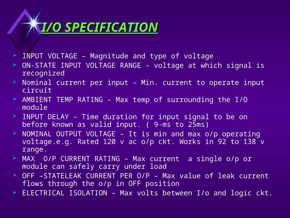
INPUT VOLTAGE – Magnitude and type of voltage ON-STATE INPUT VOLTAGE RANGE – voltage at which signal is
recognized Nominal current per input – Min. current to operate input circuit AMBIENT TEMP RATING – Max temp of surrounding the I/O
module INPUT DELAY – Time duration for input signal to be on before
known as valid input. ( 9-ms to 25ms) NOMINAL OUTPUT VOLTAGE – It is min and max o/p operating
voltage.e.g. Rated 120 v ac o/p ckt. Works in 92 to 138 v range. MAX O/P CURRENT RATING – Max current a single o/p or
module can safely carry under load OFF –STATELEAK CURRENT PER O/P – Max value of leak current
flows through the o/p in OFF position ELECTRICAL ISOLATION – Max volts between I/o and logic ckt.

The power supply gives the voltage required for electronics module (I/O Logic signals, CPU, memory unit and peripheral devices) of the PLC from the line supply.
The power supply provides isolation necessary to protect the solid state devices from most high voltage line spikes.
As I/O is expanded, some PLC may require additional power supplies in order to maintain proper power levels.
P L C : Power Supply P L C : Power Supply

It is path for the transmission of the signal . Bu system is responsible for the signal exchange between processor and I/O modules
The bus system comprise of several single line ie wires / tracks
P L C : Bus System P L C : Bus System

Relay ConnectionRelay Connection
L2
L1
1
2
3
4
L2
L1
1
2
3
4
CR
M
M
CR CL
M
M M M
T1 T2 T3
L1 L2 L3
MOTOR
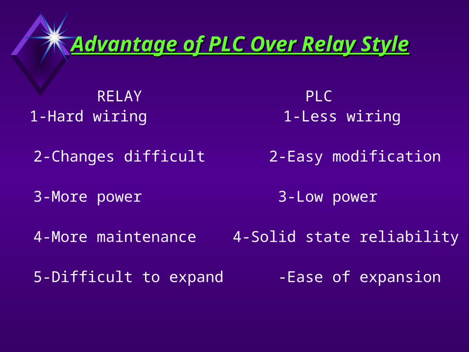
Advantage of PLC Over Relay Advantage of PLC Over Relay StyleStyle
RELAY PLC 1-Hard wiring 1-Less wiring
2-Changes difficult 2-Easy modification
3-More power 3-Low power
4-More maintenance 4-Solid state reliability
5-Difficult to expand -Ease of expansion
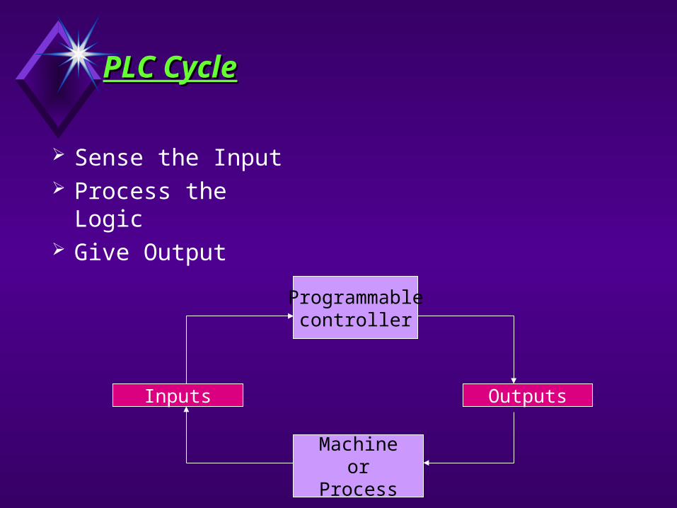
PLC CyclePLC Cycle
Outputs
Machineor
Process
Programmablecontroller
Inputs
Sense the Input Process the Logic Give Output

PLC Signal FlowPLC Signal Flow
Programming Terminal
O:0/7
O:0/7
O:1/5
Output Devices
Output ModulesProcessor MemoryInput Module
Input DevicesLadder Program
O:0/7
O:1/5
I:0/6
I:1/4
O:1/5
I:0/6
I:1/4
I:0/6
I:1/4
Data InputImage Table
OutputImage Table
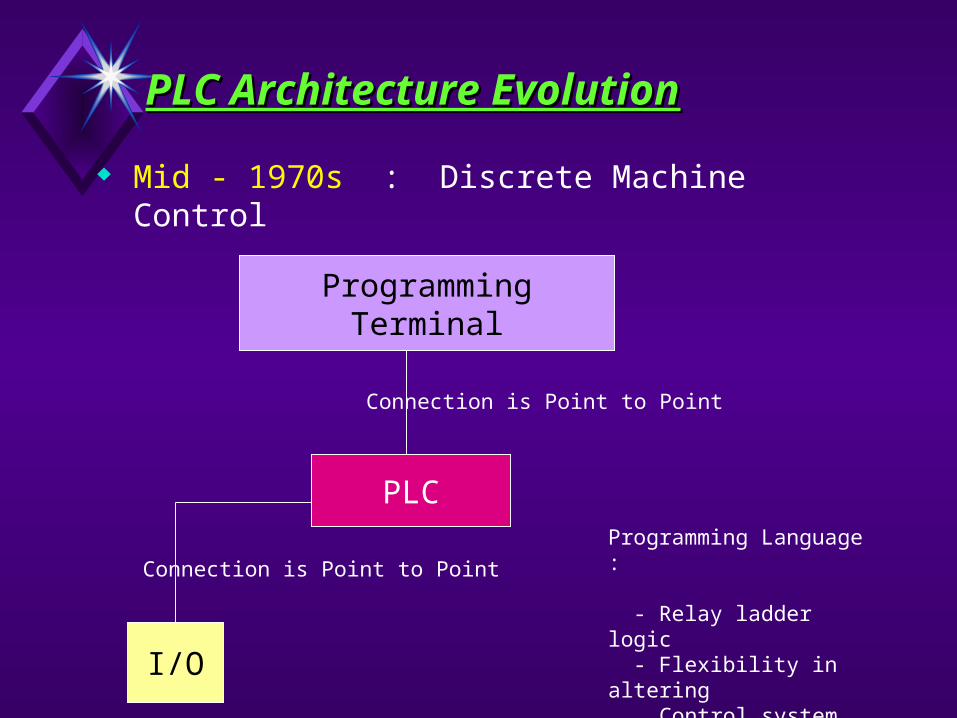
PLC Architecture EvolutionPLC Architecture Evolution
Mid - 1970s : Discrete Machine Control
ProgrammingTerminal
PLC
I/O
Connection is Point to Point
Programming Language :
- Relay ladder logic - Flexibility in altering Control system operation
Connection is Point to Point

Early - to - Mid 1980 : Discrete and Process Control
PLC Architecture EvolutionPLC Architecture Evolution
Reasonable ComputerRunning PLC
Programming Software
PLC
I/O
Programming Language :
- Ladder Program - PID - Data Storage
MS - DOS

PLC Architecture EvolutionPLC Architecture Evolution
Late 1980’s to early 1990’s : Discrete and Process Control
PC running PLC Programming Software
PLC
I/O
Connection in networked allowing Multiple PLC
PLC became a part of the developing enterprise resource system
Windows
PLC

TodayToday : : Distributed I/O ModulesDistributed I/O Modules
Distributed I/O modules
PLC
Distributed I/O scanner
Data Communication Bus
PLC Architecture PLC Architecture EvolutionEvolution

Remote I/O Network
SPLITTERS
FIBER OPTIC LINK
TAPS
Remote I/O
Today : Today : Hot Redundant SystemHot Redundant System
PLC Architecture EvolutionPLC Architecture Evolution
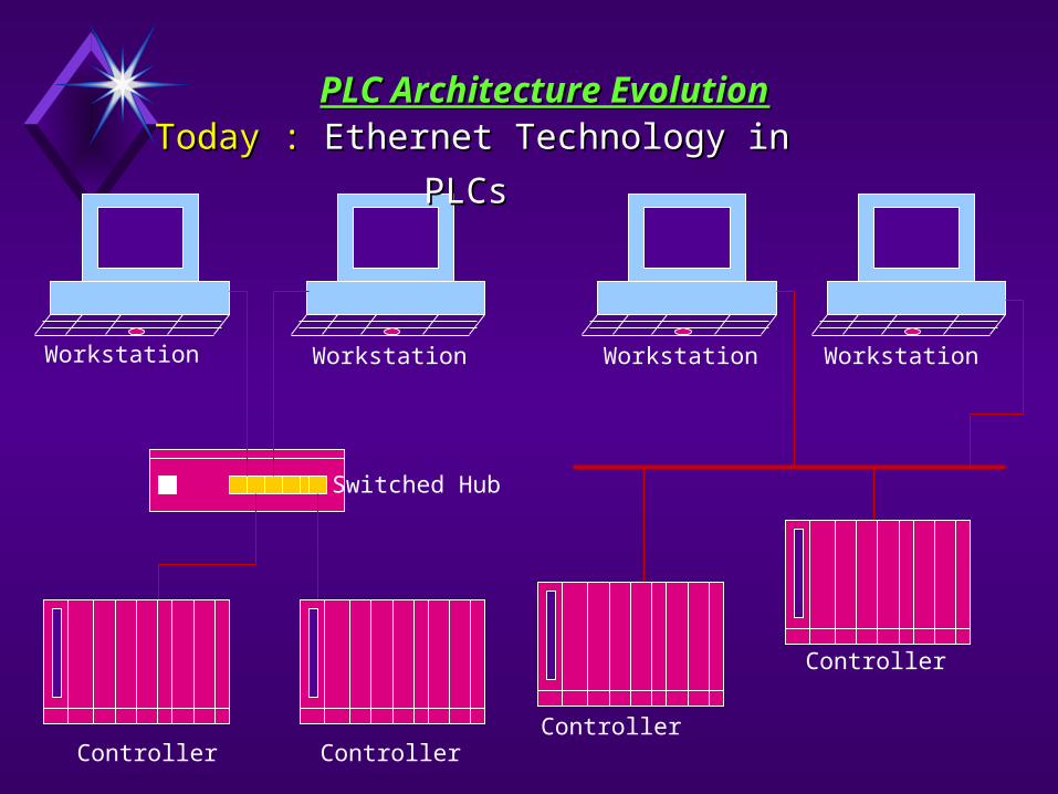
Controller ControllerController
Controller
Workstation Workstation Workstation Workstation
Switched Hub
PLC Architecture EvolutionPLC Architecture Evolution
Today : Today : Ethernet Technology in PLCsEthernet Technology in PLCs

RemotePlatform
Wireless Modem
Wireless Modem
PLC
H M I Display
PC
PLC Architecture EvolutionPLC Architecture Evolution
Today : Today : Wireless communicationWireless communication
PLC

PLC Systems of various vendors PLC Systems of various vendors
Siemens S5 -110U, 115U, 135U S7 - 200, 300, 400
Allen Bradley Micrologix 1000, 1200,
1500 SLC 5/01, 5/02, 5/03 PLC 5/10, 5/25 and 5/40
Modicon Nano Micro Premium Quantum

8 Analog Inputs 1 Analog Output
Up/Down Fast Counter
Up Counter
Programming Terminal PC Connection
Unitelway Port for connection of up to 5 Slaves
PCMCIA memory expansion port
PCMCIA communications port
TSX37-22
Built in display for I/O (in-rack, AS-i) and Diag
I/O Modules
Configuration of PLC : Configuration of PLC : ModiconModicon
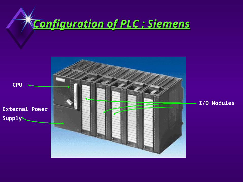
Configuration of PLC : Configuration of PLC : SiemensSiemens
CPU
External Power
Supply
I/O Modules

Configuration of PLC : Allen Configuration of PLC : Allen BradleyBradley
CPU
Power Supply I/O Modules

Configuration of PLC : GE FANUCConfiguration of PLC : GE FANUC
CPU
I/O Modules Back plane

PLC Programming StandardsPLC Programming Standards
The open, manufacturer-independent programming standard for automation is IEC 61131-3. You can thus choose what configuration interface you wish to use when writing your application :
Ladder Diagram Statement List Instruction List Function Block Diagram Sequential Function Chart Structured Text

Scan RateScan Rate
The completion of one cycle of the sequence is called- SCAN
Time required for one cycle is called SCAN TIME

Cost of hardware, software, Integration Engineering, Design, Installation, Start-up and Commissioning, Validation documentation and Execution, Training, Spare parts, Maintenance, System service contract and system life cycle.
Reliability, Flexibility, Scalability and Validatability. Ease of Database configuration, Graphics
development, Interlocks and Batch processing. Integration of High-level Application. Control Philosophy for Centralized versus Remote
Operator Console or both. Compliance with an Industry batch standard such as
ISA SP88 and new Communication Protocol.
PLC DCS Selection CriteriaPLC DCS Selection Criteria
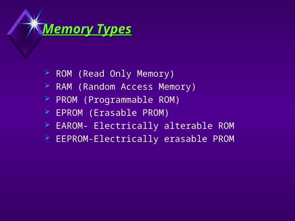
Memory TypesMemory Types
ROM (Read Only Memory) RAM (Random Access Memory) PROM (Programmable ROM) EPROM (Erasable PROM) EAROM- Electrically alterable ROM EEPROM-Electrically erasable PROM

Binary System Binary System
BIT – Each digit of a binary number BYTE – Group of 8 bit WORD – Group of one or more byte LSB – Least significant bit or
smallest value MSB – Most significant bit or largest
value
1 0234567
8 BIT WORD
LSBMSB
BYTE BYTE
18 BIT WORD
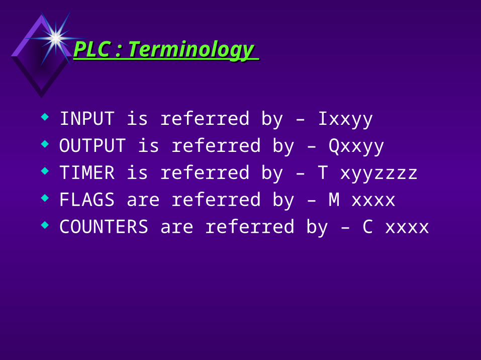
PLC : Terminology PLC : Terminology
INPUT is referred by – Ixxyy OUTPUT is referred by – Qxxyy TIMER is referred by – T xyyzzzz FLAGS are referred by – M xxxx COUNTERS are referred by – C xxxx